CN110060297B - Information processing apparatus, information processing system, information processing method, and storage medium - Google Patents
Information processing apparatus, information processing system, information processing method, and storage medium Download PDFInfo
- Publication number
- CN110060297B CN110060297B CN201910037242.0A CN201910037242A CN110060297B CN 110060297 B CN110060297 B CN 110060297B CN 201910037242 A CN201910037242 A CN 201910037242A CN 110060297 B CN110060297 B CN 110060297B
- Authority
- CN
- China
- Prior art keywords
- learning
- unit
- virtual space
- image
- information processing
- Prior art date
- Legal status (The legal status is an assumption and is not a legal conclusion. Google has not performed a legal analysis and makes no representation as to the accuracy of the status listed.)
- Active
Links
- 230000010365 information processing Effects 0.000 title claims abstract description 99
- 238000003672 processing method Methods 0.000 title claims abstract description 8
- 238000012545 processing Methods 0.000 claims abstract description 45
- 238000004364 calculation method Methods 0.000 claims description 49
- 238000005259 measurement Methods 0.000 claims description 46
- 238000004590 computer program Methods 0.000 claims description 12
- 230000007613 environmental effect Effects 0.000 claims description 10
- 230000006870 function Effects 0.000 claims description 8
- 238000009877 rendering Methods 0.000 claims description 3
- 238000000034 method Methods 0.000 description 86
- 238000003384 imaging method Methods 0.000 description 55
- 230000008569 process Effects 0.000 description 50
- 238000012986 modification Methods 0.000 description 18
- 230000004048 modification Effects 0.000 description 18
- 238000010586 diagram Methods 0.000 description 17
- 238000005286 illumination Methods 0.000 description 6
- 238000013527 convolutional neural network Methods 0.000 description 5
- 241001465754 Metazoa Species 0.000 description 3
- 238000003909 pattern recognition Methods 0.000 description 3
- 230000000007 visual effect Effects 0.000 description 3
- 230000003190 augmentative effect Effects 0.000 description 2
- 230000008859 change Effects 0.000 description 2
- 238000004891 communication Methods 0.000 description 2
- 238000010801 machine learning Methods 0.000 description 2
- 239000011159 matrix material Substances 0.000 description 2
- 230000002194 synthesizing effect Effects 0.000 description 2
- 230000009466 transformation Effects 0.000 description 2
- 230000015572 biosynthetic process Effects 0.000 description 1
- 238000006243 chemical reaction Methods 0.000 description 1
- 230000006835 compression Effects 0.000 description 1
- 238000007906 compression Methods 0.000 description 1
- 230000010485 coping Effects 0.000 description 1
- 238000013135 deep learning Methods 0.000 description 1
- 238000013461 design Methods 0.000 description 1
- 230000005484 gravity Effects 0.000 description 1
- 230000004807 localization Effects 0.000 description 1
- 238000013507 mapping Methods 0.000 description 1
- 230000003287 optical effect Effects 0.000 description 1
- 238000005457 optimization Methods 0.000 description 1
- 230000002787 reinforcement Effects 0.000 description 1
- 238000003786 synthesis reaction Methods 0.000 description 1
Images


Classifications
-
- G—PHYSICS
- G05—CONTROLLING; REGULATING
- G05D—SYSTEMS FOR CONTROLLING OR REGULATING NON-ELECTRIC VARIABLES
- G05D1/00—Control of position, course, altitude or attitude of land, water, air or space vehicles, e.g. using automatic pilots
- G05D1/04—Control of altitude or depth
-
- G—PHYSICS
- G05—CONTROLLING; REGULATING
- G05D—SYSTEMS FOR CONTROLLING OR REGULATING NON-ELECTRIC VARIABLES
- G05D1/00—Control of position, course, altitude or attitude of land, water, air or space vehicles, e.g. using automatic pilots
- G05D1/10—Simultaneous control of position or course in three dimensions
-
- G—PHYSICS
- G06—COMPUTING; CALCULATING OR COUNTING
- G06N—COMPUTING ARRANGEMENTS BASED ON SPECIFIC COMPUTATIONAL MODELS
- G06N20/00—Machine learning
-
- G—PHYSICS
- G06—COMPUTING; CALCULATING OR COUNTING
- G06T—IMAGE DATA PROCESSING OR GENERATION, IN GENERAL
- G06T7/00—Image analysis
- G06T7/50—Depth or shape recovery
-
- G—PHYSICS
- G06—COMPUTING; CALCULATING OR COUNTING
- G06T—IMAGE DATA PROCESSING OR GENERATION, IN GENERAL
- G06T7/00—Image analysis
- G06T7/70—Determining position or orientation of objects or cameras
- G06T7/73—Determining position or orientation of objects or cameras using feature-based methods
- G06T7/75—Determining position or orientation of objects or cameras using feature-based methods involving models
-
- G—PHYSICS
- G06—COMPUTING; CALCULATING OR COUNTING
- G06T—IMAGE DATA PROCESSING OR GENERATION, IN GENERAL
- G06T2207/00—Indexing scheme for image analysis or image enhancement
- G06T2207/10—Image acquisition modality
- G06T2207/10016—Video; Image sequence
-
- G—PHYSICS
- G06—COMPUTING; CALCULATING OR COUNTING
- G06T—IMAGE DATA PROCESSING OR GENERATION, IN GENERAL
- G06T2207/00—Indexing scheme for image analysis or image enhancement
- G06T2207/10—Image acquisition modality
- G06T2207/10024—Color image
-
- G—PHYSICS
- G06—COMPUTING; CALCULATING OR COUNTING
- G06T—IMAGE DATA PROCESSING OR GENERATION, IN GENERAL
- G06T2207/00—Indexing scheme for image analysis or image enhancement
- G06T2207/20—Special algorithmic details
- G06T2207/20081—Training; Learning
-
- G—PHYSICS
- G06—COMPUTING; CALCULATING OR COUNTING
- G06T—IMAGE DATA PROCESSING OR GENERATION, IN GENERAL
- G06T2207/00—Indexing scheme for image analysis or image enhancement
- G06T2207/20—Special algorithmic details
- G06T2207/20084—Artificial neural networks [ANN]
-
- G—PHYSICS
- G06—COMPUTING; CALCULATING OR COUNTING
- G06T—IMAGE DATA PROCESSING OR GENERATION, IN GENERAL
- G06T2207/00—Indexing scheme for image analysis or image enhancement
- G06T2207/30—Subject of image; Context of image processing
- G06T2207/30244—Camera pose
-
- G—PHYSICS
- G06—COMPUTING; CALCULATING OR COUNTING
- G06T—IMAGE DATA PROCESSING OR GENERATION, IN GENERAL
- G06T2207/00—Indexing scheme for image analysis or image enhancement
- G06T2207/30—Subject of image; Context of image processing
- G06T2207/30248—Vehicle exterior or interior
Landscapes
- Engineering & Computer Science (AREA)
- Physics & Mathematics (AREA)
- General Physics & Mathematics (AREA)
- Theoretical Computer Science (AREA)
- Computer Vision & Pattern Recognition (AREA)
- Software Systems (AREA)
- Automation & Control Theory (AREA)
- Radar, Positioning & Navigation (AREA)
- Aviation & Aerospace Engineering (AREA)
- Remote Sensing (AREA)
- Medical Informatics (AREA)
- Evolutionary Computation (AREA)
- Data Mining & Analysis (AREA)
- Artificial Intelligence (AREA)
- Computing Systems (AREA)
- General Engineering & Computer Science (AREA)
- Mathematical Physics (AREA)
- Image Analysis (AREA)
- Length Measuring Devices By Optical Means (AREA)
Abstract
Information processing apparatus, information processing system, information processing method, and storage medium. An image of a virtual space corresponding to a physical space and geometric information of the virtual space are generated as learning data. Learning processing of the learning model is performed using the learning data. The position and/or orientation of the image capturing apparatus is calculated based on geometric information output from a learning model into which a captured image of a physical space captured by the image capturing apparatus is input.
Description
Technical Field
The present invention relates to an information processing apparatus, system, information processing method, and storage medium, and in particular, to a technique of obtaining a position and/or a posture.
Background
For various purposes such as self position/orientation estimation of a robot or a motor vehicle, or alignment between a physical space (physical space) and a virtual object in mixed reality/augmented reality, measurement of the position and/or orientation (hereinafter, referred to as position/orientation) of an image pickup apparatus based on image information is used.
Tateno, F.Tombari, I.Laina and N.Navab, "CNN-SLAM: real-time dense monocular SLAM with learned depth prediction ", IEEE international conference on Computer Vision and Pattern Recognition (CVPR), 2017 discloses the following method: geometric information (depth information) as an index for calculating a position/orientation is estimated from image information using a learning model learned in advance, and position/orientation information is calculated based on the estimated geometric information.
Tateno, F.Tombari, I.Laina and N.Navab, "CNN-SLAM: real-time dense monocular SLAM with learned depth prediction ", IEEE international conference on Computer Vision and Pattern Recognition (CVPR), 2017 assumes that the appearance of a scene of an image for generating a learning model is similar to that of a scene included in an input image captured by an image capturing apparatus. Therefore, there is a need for a scheme to improve the position/orientation calculation accuracy in the case where the appearance of the scene is dissimilar.
Disclosure of Invention
The present invention provides a technique for accurately obtaining a position and/or a posture.
According to a first aspect of the present invention, there is provided an information processing apparatus comprising: a generation unit configured to generate an image of a virtual space corresponding to a physical space and geometric information of the virtual space as learning data; a learning unit configured to perform learning processing of a learning model using learning data; and a calculation unit configured to calculate a position and/or a posture of the image capturing apparatus based on geometric information output from a learning model into which a captured image of the physical space captured by the image capturing apparatus is input.
According to a second aspect of the present invention, there is provided a system including an information processing apparatus and a control unit, the information processing apparatus including: a generation unit configured to generate an image of a virtual space corresponding to a physical space and geometric information of the virtual space as learning data; a learning unit configured to perform learning processing of a learning model using learning data; and a calculation unit configured to calculate a position and/or a posture of the image capturing apparatus based on geometric information output from a learning model into which a captured image of the physical space captured by the image capturing apparatus is input, wherein the calculation unit calculates a position and/or a posture of a vehicle including the information processing device based on the position and/or the posture of the image capturing apparatus, and the control unit is configured to perform driving control of the vehicle based on the geometric information and the position and/or the posture of the vehicle calculated by the calculation unit.
According to a third aspect of the present invention, there is provided an information processing method by an information processing apparatus, the information processing method comprising: generating an image of a virtual space corresponding to the physical space and geometric information of the virtual space as learning data; performing learning processing of the learning model using the learning data; and calculating a position and/or a posture of the image capturing apparatus based on geometric information output from a learning model into which a captured image of the physical space captured by the image capturing apparatus is input.
According to a fourth aspect of the present invention, there is provided a storage medium storing a computer program configured to cause a computer to function as: a generation unit configured to generate an image of a virtual space corresponding to a physical space and geometric information of the virtual space as learning data; a learning unit configured to perform learning processing of a learning model using learning data; and a calculation unit configured to calculate a position and/or a posture of the image capturing apparatus based on geometric information output from a learning model into which a captured image of the physical space captured by the image capturing apparatus is input.
Other features of the present invention will become apparent from the following description of exemplary embodiments (with reference to the accompanying drawings).
Drawings
Fig. 1 is a block diagram showing an example of a configuration of a system;
fig. 2 is a block diagram showing an example of the functional configuration of the information processing apparatus 10;
FIG. 3 is a flow chart of a process performed by the system;
fig. 4 is a diagram showing an example of the structure of the GUI 400;
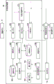
fig. 5 is a block diagram showing an example of the functional configuration of the system;
fig. 6 is a flowchart of a process performed by the information processing apparatus 20 to generate model data;
fig. 7 is a block diagram showing an example of the functional configuration of the system;
FIG. 8 is a flow chart of a process performed by the system;
fig. 9 is a block diagram showing an example of a functional configuration of the system;
FIG. 10 is a flow chart of a process performed by the system;
fig. 11 is a block diagram showing an example of the functional configuration of the system;
FIG. 12 is a flow chart of a process performed by the system;
fig. 13 is a block diagram showing an example of a functional configuration of the system;
FIG. 14 is a flow chart of a process performed by the system; and
fig. 15 is a block diagram showing an example of a hardware configuration of the computer apparatus.
Detailed Description
Embodiments of the present invention will now be described with reference to the accompanying drawings. Note that the embodiments to be described later are examples of detailed implementations of the present invention or detailed embodiments of configurations described in the appended claims.
First embodiment
In the present embodiment, a system configured to calculate the position and/or posture of the motor vehicle (hereinafter, "position and/or posture" will be referred to as position/posture) for automatic driving of the motor vehicle will be described. An example of the configuration of the system according to the present embodiment will be described with reference to the block diagram of fig. 1.
The image pickup unit 11 is fixedly attached to the rear side of the windshield of the motor vehicle 1, toward the advancing direction (direction indicated by an arrow) of the motor vehicle 1, and picks up a moving image (movie) of the environment (physical space or scene) in the advancing direction. The image (captured image) of each frame of the moving image captured by the image capturing unit 11 is output to the information processing apparatus 10. The image pickup unit 11 is, for example, a video camera (RGB color video camera) capable of capturing a color moving image. Note that the attachment position of the imaging unit 11 is not limited to a specific attachment position, and may be a position where the environment in the forward direction of the motor vehicle 1 can be imaged. In addition, the relative position/orientation relation between the motor vehicle 1 and the image pickup unit 11 is calibrated in advance, and is registered as known information (bias information) in the information processing apparatus 10.
The display unit 12 is fixedly attached near the dashboard of the motor vehicle 1 and includes a touch screen picture (touch panel screen). The display unit 12 may display various information output from the information processing apparatus 10 or the driving control unit 13, thereby providing various information to the driver or the occupant in the motor vehicle 1. In addition, the driver or the passenger in the motor vehicle 1 can make various operation inputs such as a touch operation and a swipe operation on the touch screen, thereby making various inputs to the information processing apparatus 10. Note that the display unit 12 need not always include a touch screen, and may include: a display screen configured to display information; and a user interface such as a button group or the like for receiving an operation input from a driver or an occupant in the motor vehicle 1.
The information processing apparatus 10 estimates geometric information of a scene in which the motor vehicle 1 is traveling and a position/orientation of the motor vehicle 1 based on the image captured by the image capturing unit 11, and outputs the estimated geometric information and the position/orientation of the motor vehicle 1 to the driving control unit 13. The information processing apparatus 10 also performs learning processing for estimating a learning model to be used. In addition, the information processing apparatus 10 outputs various information to be displayed to the display unit 12.
The driving control unit 13 decides the rotation torque of the wheels of the motor vehicle 1 and the forward direction of the motor vehicle 1 based on the geometric information and the position/orientation output from the information processing device 10, and notifies the decided rotation torque and forward direction to the actuator unit 14. The actuator unit 14 controls driving of the wheels of the motor vehicle 1 based on the rotational torque and the forward direction of the wheels notified from the drive control unit 13. Note that the information decided by the drive control unit 13 is not limited to the rotational torque of the wheels of the motor vehicle 1 and the forward direction of the motor vehicle 1, and may be any information as long as it relates to the drive control of the motor vehicle 1. For example, information about the braking or flashing (blinker) of the motor vehicle 1 can be provided. The actuator unit 14 controls driving of wheels of the motor vehicle 1 based on information from the drive control unit 13.
As described above, the motor vehicle 1 is a motor vehicle that performs automatic driving by determining the rotational torque and the forward direction of the wheels of the motor vehicle 1 based on the geometric information and the position/orientation estimated from the captured image, and controlling the driving of the wheels of the motor vehicle 1 based on the rotational torque and the forward direction.
Next, an example of the functional configuration of the information processing apparatus 10 will be described with reference to the block diagram of fig. 2. Note that the components shown in fig. 2 are only examples of components capable of implementing respective processes which will be described later as processes to be performed by the information processing apparatus 10. For example, several functional units may be integrated in one functional unit, or one functional unit may be divided into a plurality of functional units on a functional basis. The control unit 199 controls the operation of the entire information processing apparatus 10.
The holding unit 101 holds model data of objects present in the environment in which the motor vehicle 1 is traveling around the motor vehicle 1. An "object present in the environment in which the motor vehicle 1 is traveling around the motor vehicle 1" is, for example, a physical object present in the environment in which the motor vehicle 1 is traveling, such as a road, a sign, a traffic signal, a building, a natural object, a person, an animal, a motor vehicle, a bicycle, or the like. In addition, for example, in the case where an object appears as a polygon, the "model data of the object" includes polygon data (normal vector of each polygon, three-dimensional coordinates of vertices of the polygon, color and attribute of the polygon, and the like) and texture data. In the case where the object appears as a point group, the "model data of the object" includes three-dimensional coordinates of each point in the point group. In addition, each point may have color information. As described above, the model data of the object may be any data as long as it is data representing the geometry of the object.
The display control unit 102 controls the display on the display unit 12, and acquires parameters (viewpoint parameters and environmental parameters) input by the driver or the occupant in the motor vehicle 1 by performing an operation such as a touch operation or a swipe operation on the display unit 12.
The viewpoint parameters are parameters related to viewpoints (virtual viewpoints) set in a virtual space formed by the following virtual objects (models), and include, for example, configuration parameters, imaging parameters, and moving speed parameters: the virtual object generated based on the model data held by the holding unit 101. The configuration parameters include parameters such as the position/posture of each virtual viewpoint in the virtual space and the number of virtual viewpoints. The shooting parameters include: internal parameters of the virtual viewpoints, such as focal length and principal point of each virtual viewpoint, etc.; and parameters such as exposure time and focus position of each virtual viewpoint. The movement speed parameter is a parameter representing the movement speed of the virtual viewpoint.
On the other hand, the environment parameters are parameters related to a virtual space formed by a virtual object (model) generated based on model data held by the holding unit 101, and include, for example, lighting parameters, object parameters, and region parameters. The lighting parameters are parameters for defining lighting conditions that change based on changes in time, season, weather state, and the like. The object parameters are parameters related to the type, number, position, posture, size, etc. of the model configured in the virtual space. The regional parameters are parameters such as the name and location of the country, place, and region in which the motor vehicle 1 is traveling, and regulations based on laws and regulations of the region (e.g., whether the traffic lane of a road is right or left, maximum speed of an expressway), and the like.
The display control unit 102 outputs the viewpoint parameter input by the driver or the occupant in the motor vehicle 1 through the operation display unit 12 to the input unit 103, and outputs the environmental parameter input by the driver or the occupant in the motor vehicle 1 through the operation display unit 12 to the input unit 104.
The input unit 103 outputs the viewpoint parameter received from the display control unit 102 to the generation unit 105, and the input unit 104 outputs the environment parameter received from the display control unit 102 to the generation unit 105. Note that the method of inputting the viewpoint parameter and the environment parameter to the generation unit 105 is not limited to the above-described method, and for example, the viewpoint parameter and the environment parameter registered in advance in a memory provided in the information processing apparatus 10 may be input to the generation unit 105.
The generation unit 105 generates an image (virtual space image) representing the virtual space defined by the model data held by the holding unit 101 and the environmental parameters input from the input unit 104, when viewed from the virtual viewpoint defined by the viewpoint parameters input from the input unit 103. In addition, the generation unit 105 generates geometric information (depth map) of the virtual space when viewed from the virtual viewpoint. For example, the generating unit 105 generates a model based on the model data held by the holding unit 101, and configures the model in a virtual space in the number, position, posture, size, and the like defined by object parameters included in the environment parameters, thereby constructing the virtual space. Note that the model is configured as prescribed, for example, by a regional parameter. For example, when a model of an automobile is arranged, whether or not the model is arranged on the right lane or the left lane is determined in accordance with the specifications of each region defined by the region parameters. The generation unit 105 generates, as a virtual space image, an image representing the virtual space constructed when viewed from a virtual viewpoint defined by viewpoint parameters under illumination conditions defined by illumination parameters included in environment parameters. Note that the virtual space image generated by the generation unit 105 is preferably similar in appearance to the image captured by the image capturing unit 11. The generated virtual space image is similar in appearance to the image captured by the image capturing unit 11 if the viewpoint parameter and the environment parameter are appropriately set to conform to the design information, the driving condition, and the driving environment of the motor vehicle 1. Therefore, position/orientation calculation can be performed accurately. The generation unit 105 also generates geometric information of the constructed virtual space when viewed from a virtual viewpoint. Note that in the present embodiment, the virtual space image and the geometric information (depth map) are generated at the same or almost the same scale, that is, at scales within a predetermined range. More specifically, the virtual space image and the geometric information (depth map) are generated by rendering (rendering) at the same or almost the same viewing angle, that is, at a viewing angle within a predetermined range. Then, the generation unit 105 outputs the generated set of the virtual space image and the geometric information as learning data to the generation unit 106. Note that the generation unit 105 changes the viewpoint parameter input from the input unit 103 or the environment parameter input from the input unit 104, thereby generating different "sets of viewpoint parameter and environment parameter". For example, the lighting parameters included in the environment parameters may be changed to generate environment parameters corresponding to various lighting conditions (time, season, weather state, etc.). Optionally, object parameters included in the environment parameters may be changed to generate environment parameters corresponding to various model configuration states as follows: adding models to be configured in the virtual space or deleting models. In addition, the zone parameters included in the environment parameters may be changed to generate environment parameters corresponding to various zones. The generation unit 105 generates learning data corresponding to each set, thereby generating learning data corresponding to various viewpoint parameters or various environmental parameters. In addition, when learning data is generated, the degree of detail of the image can be increased (the compression rate can be reduced) for an object important for the automatic driving of the motor vehicle 1, such as a sign or a traffic signal.
For each learning data received from the generating unit 105, the generating unit 106 obtains the difference between the information output from the learning model to which the virtual space image included in the learning data is input and the geometric information (the supervision data) included in the learning data. Then, the generation unit 106 updates the learning model so that the difference is small for each learning data, thereby performing learning processing (such as a method of back propagation or the like) of the learning model. In this embodiment, a case where CNN (Convolutional Neural Network ) is applied to a learning model will be described. However, any learning model may be used as long as it is a learning model configured to output corresponding geometric information when an image is input. For example, a machine-learned model may be used as the learning model, and the learning model is not limited to CNN.
By generating learning data corresponding to various conditions (states) and using the learning data for learning of the learning model, a more robust learning model can be generated. The generation unit 106 stores the learned learning model in the holding unit 107.
The input unit 108 acquires captured images (image information) of the respective frames output from the image capturing unit 11, and outputs the acquired captured images to the estimation unit 109, the calculation unit 110, and the generation/update unit 111 in the subsequent stage. The input unit 108 is formed of, for example, an image capturing board.
The estimation unit 109 reads out the learning model stored in the holding unit 107, and inputs the captured image received from the input unit 108 to the read-out learning model, thereby outputting the geometric information output from the learning model to the calculation unit 110 and the generation/update unit 111 at the subsequent stage.
Note that in the present embodiment, the captured image and the geometric information output from the learning model have the same or almost the same scale. That is, the captured image and the geometric information output from the learning model have the same or almost the same viewing angle. This can be achieved by setting the same or almost the same angle of view for the captured image, the virtual space image generated by the generation unit 105, and the geometric information. If the scale of the photographed image is different from the scale of the geometric information output from the learning model, the geometric information output from the learning model is multiplied by the ratio of the viewing angle, thereby adjusting the scale to the scale of the photographed image.
The calculation unit 110 obtains the position/orientation of the image pickup unit 11 using the captured image sent from the input unit 108 and the geometric information sent from the estimation unit 109, and converts the obtained position/orientation into the position/orientation of the motor vehicle 1 using the above-described offset information. Then, the calculation unit 110 sends the converted position/orientation of the motor vehicle 1 and the geometric information output from the estimation unit 109 to the driving control unit 13 and the generation/update unit 111 at the subsequent stage.
Here, an example of a method of calculating the position/orientation of the image capturing unit 11 by the calculation unit 110 will be described. More specifically, each pixel of the previous frame is projected to the captured image (current frame) captured at time t based on geometric information (previous geometric information) output from a learning model to which the captured image (previous frame) captured at time t' before time t is input. Here, "projective" refers to calculating where each pixel of the previous frame is located in the current frame. More specifically, the image coordinates (u t-1 ,v t-1 ) Internal parameters (f) of the imaging unit 11 x ,f y ,c x And c y ) And the depth value D of the pixel of interest in the previous geometric information, the calculation unit 110 calculates

Thus, the calculation unit 110 can obtain the three-dimensional coordinates (X t-1 ,Y t-1 ,Z t-1 )。
Here, the camera coordinate system is, for example, a coordinate system in which an origin is located at a position of the image capturing unit 11 (for example, a position of an image sensor) and three axes orthogonal to each other at the origin (including two axes orthogonal to each other with respect to a visual axis direction of the image capturing unit 11 at the origin and three axes in total along one axis of the visual axis direction of the image capturing unit 11) are used as X-axis, Y-axis, and Z-axis.
Here, let t (t-1)→t Is a transformation matrix of the position of the image capturing unit 11 capturing the current frame with respect to the position of the image capturing unit 11 capturing the previous frame, let R (t-1)→t Is a transformation matrix of the pose of the image capturing unit 11 capturing the current frame with respect to the pose of the image capturing unit 11 capturing the previous frame. At this time, t is used (t-1)→t And R is (t-1)→t The calculation unit 110 calculates

Thereby, the three-dimensional coordinates (X t ,Y t ,Z t )。
Next, the calculation unit 110 calculates

Thereby, the three-dimensional coordinates (X t ,Y t ,Z t ) Conversion to image coordinates (u) t ,v t )。
In this embodiment, the processing according to the above formulas (1) to (3) is referred to as projection. The calculation unit 110 performs the projection using feature points such as angles or edges obtained separately in the previous frame as the pixel of interest, or using all of themThe pixel performs this projection as a pixel of interest, thereby obtaining the corresponding image coordinates in the current frame. Then, the calculation unit 110 calculates t (t-1)→t And R is (t-1)→t So that the image coordinate (u t-1 ,v t-1 ) The luminance value of the pixel at the position is compared with the luminance value of the pixel in the current frame as the projection destination of the pixel (the image coordinates are (u) t ,v t ) A luminance difference between luminance values is minimized.
Using the position t of the camera unit 11 taking the previous frame on the world coordinate system w→(t-1) And posture R w→(t-1) The calculation unit 110 calculates

Thus, the calculation unit 110 calculates the position t of the image capturing unit 11 capturing the current frame on the world coordinate system w→t And posture R w→t 。
Here, the world coordinate system is a coordinate system having an origin at one point in the physical space and using three axes orthogonal to each other at the origin as an X-axis, a Y-axis, and a Z-axis. Note that the calculation unit 110 may calculate the position/orientation of the image capturing unit 11 using a three-dimensional map generated/updated by the generation/update unit 111 in addition to the geometric information from the estimation unit 109, and using a SLAM (simultaneous localization and mapping) technique. Using K.Tateno, F.Tombari, I.Laina and N.Navab, "CNN-SLAM: real-time dense monocular SLAM with learned depth prediction ", IEEE International computer Vision and Pattern recognition Conference (CVPR), method of 2017, or method using Engel et al (J. Engel, And d.cremers. Lsd-SLAM: larget-Scale Direct Monocular SLAM. European computer vision International conference (ECCV), 2014) can be used for position/orientation calculations. When a three-dimensional map is generated/updated using the SLAM technique, geometric information can be accumulated for a road once it is driven.
The generation/update unit 111 generates and updates a three-dimensional map in the environment in which the motor vehicle 1 is traveling, using the captured image input from the input unit 108, the geometric information input from the estimation unit 109, and the position/orientation input from the calculation unit 110. The generation/update unit 111 outputs the generated/updated three-dimensional map to the calculation unit 110 and the driving control unit 13.
In the present embodiment, when calculation of the position/orientation of the motor vehicle using the SLAM technique and generation of the three-dimensional map of the environment are performed simultaneously, the three-dimensional map is used. For example, the three-dimensional map may be a combination of point group data and color information, or may be a collection of key frame information having a depth map and color information and associated with a position/gesture in the environment.
Next, processing performed by the system according to the present embodiment will be described with reference to the flowchart of fig. 3. In step S101, under the control of the control unit 199, an initialization process is performed in the information processing apparatus 10. In the initialization process, for example, the generating unit 105 reads out the model data from the holding unit 101, and the calculating unit 110 reads out the internal parameters of the imaging unit 11. Thus, in the initialization process, each functional unit reads out or sets data to be used by itself to execute the process. For example, the timing at which the initialization process is started is when the driver of the motor vehicle 1 starts controlling the motor vehicle 1, or when the mode is switched from the manual driving mode to the automatic driving mode.
In step S102, the display control unit 102 displays a GUI (graphical user interface) configured to set viewpoint parameters and environment parameters for a driver or occupant in the motor vehicle 1 on the display screen of the display unit 12. Fig. 4 shows an example of the structure of the GUI400 displayed on the display unit 12 in step S102.
In the GUI400, the area 41 is an area in which an operation unit for setting viewpoint parameters is arranged, and the area 42 is an area in which an operation unit for setting environment parameters is arranged.
First, the region 41 will be described. The tab 41a is used to select a virtual viewpoint as an object to which the configuration parameter is set. For example, when the user designates the tab 41a on the display screen, the name of the virtual viewpoint capable of setting the configuration parameter may be displayed in a list, and the user designates the name of the virtual viewpoint for setting the configuration parameter from among the names displayed in the list. In fig. 4, a virtual viewpoint "camera 1" is specified.
The region 41b is a region for inputting the position of the virtual viewpoint in the virtual space. For example, when the user designates the region 41b on the display screen, a user interface for inputting a numerical value is displayed on the display screen, and the user inputs a position (numerical value) to the region 41b using the user interface. The position input to the region 41b is a position on a coordinate system based on the motor vehicle 1 as a reference, and is preferably a position almost identical to the position of the image pickup unit 11 (in particular, a position having almost the same height as the image pickup unit 11).
The region 41c is a region for inputting a gesture of the virtual viewpoint in the virtual space. For example, when the user designates the region 41c on the display screen, a user interface for inputting a numerical value is displayed on the display screen, and the user inputs a gesture (numerical value) to the region 41c using the user interface. The posture input to the region 41c is a posture on a coordinate system based on the motor vehicle 1 as a reference, and is preferably a posture almost identical to the posture of the image pickup unit 11 (in particular, a posture in which the visual axis direction of the image pickup unit 11 is almost identical to the posture of the virtual viewpoint). Configuration parameters included in the viewpoint parameters may be set by the tag 41a and the areas 41b and 41c.
The tab 41d is used to select a virtual viewpoint as an object to which the imaging parameter is set. For example, when the user designates the tab 41d on the display screen, the name of the virtual viewpoint that can set the imaging parameter may be displayed in a list, and the user designates the name of the virtual viewpoint for setting the imaging parameter from among the names displayed in the list. In fig. 4, a virtual viewpoint "camera 1" is specified.
The area 41e is an area for inputting a focal length of the virtual viewpoint. For example, when the user designates the region 41e on the display screen, a user interface for inputting a numerical value is displayed on the display screen, and the user inputs a focal length (numerical value) to the region 41e using the user interface.
The area 41f is an area for inputting the exposure time of the virtual viewpoint. For example, when the user designates the region 41f on the display screen, a user interface for inputting a numerical value is displayed on the display screen, and the user inputs the exposure time (numerical value) to the region 41f using the user interface. The imaging parameters included in the viewpoint parameters can be set by the tag 41b and the areas 41e and 41f.
The area 41g is an area for inputting a lower limit of the movement speed of the virtual viewpoint. For example, when the user designates the region 41g on the display screen, a user interface for inputting a numerical value is displayed on the display screen, and the user inputs a lower limit (numerical value) of the movement speed to the region 41g using the user interface.
The region 41h is a region for inputting an upper limit of the movement speed of the virtual viewpoint. For example, when the user designates the region 41h on the display screen, a user interface for inputting a numerical value is displayed on the display screen, and the user inputs an upper limit (numerical value) of the movement speed to the region 41h using the user interface.
As the upper/lower limit of the moving speed, the upper/lower limit of the range of speeds that the driver of the motor vehicle 1 normally drives may be input, or the maximum speed that the motor vehicle 1 can reach may be input as the upper limit of the moving speed. As the moving speed parameter included in the viewpoint parameter, one of speeds in a range from an upper limit to a lower limit of the moving speed (for example, one of moving speeds at intervals of 10km/h from the upper limit to the lower limit of the moving speed) is set.
Next, the region 42 will be described. The area 42a is an area for inputting time. For example, when the user designates the area 42a on the display screen, a user interface for inputting a numerical value is displayed on the display screen, and the user inputs time (numerical value) to the area 42a using the user interface. Alternatively, a time band such as morning, daytime, evening, or night may be input to the area 42a, or the time band may be selected at the area 42 b.
The tag 42b is used to select seasons. For example, when the user designates the tab 42b on the display screen, four seasons, that is, spring, summer, autumn, and winter are displayed in the list, and the user designates one of the four seasons (spring, summer, autumn, and winter) displayed in the list. In fig. 4, the season "spring" is specified.
The tag 42c is used to select a weather state. For example, when the user designates the tab 42c on the display screen, a list of weather conditions such as sunny, cloudy, rainy, and snowy is displayed, from which the user designates one weather condition. In fig. 4, the weather state "sunny" is specified. The lighting parameters included in the environmental parameters may be set by the area 42a and the tags 42b and 42 c.
The tag 42d is used to select the type of model to be configured in the virtual space. For example, when the user designates the tab 42d on the display screen, the types of models that can be configured in the virtual space are displayed in a list from which the user designates one type. In fig. 4, the type "person" is specified.
The tag 42e is used to select the number of models (the number of models to be configured in the virtual space) specified by the tag 42 d. For example, when the user designates the tab 42e on the display screen, a list of the number of models to be configured, i.e., more, medium, less, etc., is displayed, from which the user designates an item. In fig. 4, the item "many" is specified.
The tab 42f is used to select a configuration method representing how to configure the model specified by the tab 42 d. For example, when the user designates the tab 42f on the display screen, the model configuration method is displayed in the list, and the user designates one configuration method among the configuration methods displayed in the list. In fig. 4, the position "random" is specified. In the case of fig. 4, since the type of model to be configured is "person", the number of models is "many", and the model configuration method is "random", the generation unit 105 configures the models of many persons (in the number corresponding to "many") in a random manner in the virtual space. The object parameters included in the environment parameters can be set by the tags 42d, 42e, and 42 f.
The tag 42g is used to select a country corresponding to the constructed virtual space. For example, when the user designates the tag 42g on the display screen, a list of countries is displayed from which the user designates one country. In fig. 4, the country "japan" is specified.
The tag 42h is used to select a region in the country designated by the tag 42 g. For example, when the user designates the tab 42h on the display screen, a list of regions is displayed, from which the user designates one region. In fig. 4, the region "kandong" is designated.
In the case of fig. 4, since the country corresponding to the virtual space constructed is "japan" and the region is "kanto", the generation unit 105 configures the model in accordance with a predetermined rule corresponding to, for example, the country "japan" and the region "kanto". The zone parameters included in the environment parameters can be set by the tags 42g and 42 h.
Note that the setting method of information that can be set in the GUI400 shown in fig. 4 is not limited to the above method. For example, the position specification method is not limited to the input of a numerical value, and for example, one representative position among representative positions in the virtual space may be selected. In addition, for example, the gesture specifying method is not limited to input of a numerical value, and for example, one representative gesture (for example, front, rear, right, and left) among representative gestures in the virtual space may be selected. In addition, for example, the method of specifying the number of models is not limited to the above method, and a specific number may be input. The setting method of the viewpoint parameter and the environment parameter is not limited to a specific setting method. In addition, the user may input other parameters than the above viewpoint parameters and environment parameters.
When setting of the viewpoint parameter and the environment parameter using the GUI400 described above is completed, the user designates the button 43 on the display screen. When the button 43 is designated, the display control unit 102 removes the above-described GUI400 from the display screen, and sets the viewpoint parameter and the environment parameter based on the information input via the GUI 400. For example, the display control unit 102 sets the contents set in the tab 41a and the areas 41b and 41c as the configuration parameters included in the viewpoint parameters. In addition, the display control unit 102 sets the contents set in the tab 41d and the areas 41e and 41f as the imaging parameters included in the viewpoint parameters. In addition, the display control unit 102 sets one of the speeds in the range from the upper limit input to the region 41h to the lower limit input to the region 41g as the movement speed parameter included in the viewpoint parameter. In addition, for example, the display control unit 102 sets the contents set in the area 42a and the tags 42b and 42c as the illumination parameters included in the environment parameters. In addition, the display control unit 102 sets the contents set in the tags 42d, 42e, and 42f as the object parameters included in the environment parameters. In addition, the display control unit 102 sets the contents set in the tags 42g and 42h as the regional parameters included in the environmental parameters.
The display control unit 102 outputs the viewpoint parameter to the input unit 103 and outputs the environment parameter to the input unit 104. The input unit 103 outputs the viewpoint parameter received from the display control unit 102 to the generation unit 105, and the input unit 104 outputs the environment parameter received from the display control unit 102 to the generation unit 105.
In step S103, the generation unit 105 changes at least one of various parameters included in the viewpoint parameters and the environment parameters set on the GUI400 to generate a plurality of sets of "viewpoint parameters and environment parameters" different from each other. For example, when the movement speed parameter is changed, the movement speed parameter is changed in a range from the upper limit input to the region 41h to the lower limit input to the region 41 g. Accordingly, a movement speed parameter corresponding to each of a plurality of movement speeds in a range from the upper limit input to the region 41h to the lower limit input to the region 41g can be generated, and therefore, a viewpoint parameter corresponding to each of the plurality of movement speeds can be generated.
Note that the above parameter setting may be repeated by using the GUI400 a plurality of times, and sets of a plurality of "viewpoint parameters and environment parameters" different from each other are set. Then, the generation unit 105 generates sets of the virtual space image and the geometric information as learning data for the respective sets. Here, in an image captured by a camera having a higher moving speed, a stronger blur than an image captured by a camera having a lower moving speed may occur. As described above, the virtual space image generated by the generation unit 105 is preferably similar in appearance to the image captured by the imaging unit 11 under the same conditions. For this reason, blurring corresponding to the moving speed preferably also appears in the virtual space image. Therefore, the generating unit 105 performs blurring processing (blurring) in correspondence with the corresponding moving speed of the virtual space image. Thus, for example, in the virtual space image from the virtual viewpoint of the higher moving speed, a stronger blur than that in the virtual space image from the virtual viewpoint of the lower moving speed occurs, and the virtual space image resembles the appearance in the image captured by the image capturing unit 11 under the same conditions.
In step S104, the generation unit 106 performs learning processing of the learning model using the learning data generated by the generation unit 105. In step S105, the generation unit 106 stores the learning model learned in step S104 in the holding unit 107.
In step S106, the image capturing unit 11 outputs the captured image to the input unit 108 of the subsequent stage. In step S107, the input unit 108 acquires a captured image output from the image capturing unit 11, and outputs the acquired captured image to the estimation unit 109, the calculation unit 110, and the generation/update unit 111 in the subsequent stage.
In step S108, the estimation unit 109 estimates geometric information from the captured image received from the input unit 108. In this estimation process, the estimation unit 109 reads out the learning model stored in the holding unit 107, and acquires geometric information output from the read-out learning model to which the captured image received from the input unit 108 is input as an estimation result. The estimation unit 109 outputs the geometric information to the calculation unit 110 and the generation/update unit 111 of the subsequent stage.
In step S109, the calculation unit 110 obtains the position/orientation of the image capturing unit 11 using the captured image sent from the input unit 108 and the geometric information sent from the estimation unit 109, and converts the obtained position/orientation into the position/orientation of the motor vehicle 1 using the above-described offset information. Then, the calculation unit 110 sends the converted position/orientation of the motor vehicle 1 and the geometric information output from the estimation unit 109 to the driving control unit 13 and the generation/update unit 111 at the subsequent stage.
The process of step S110 is a process performed only when the setting using the SLAM technique is completed. If the setting using the SLAM technique is not completed, after step S109, the process skips step S110 and proceeds to step S111.
In step S110, the generation/update unit 111 generates and updates a three-dimensional map in the environment in which the motor vehicle 1 is traveling, using the captured image input from the input unit 108, the geometric information input from the estimation unit 109, and the position/orientation input from the calculation unit 110. Then, the generation/update unit 111 outputs the generated/updated three-dimensional map to the calculation unit 110 and the driving control unit 13. The generation/update unit 111 performs an optimization process on the three-dimensional map in each process or at a predetermined timing (for example, one of several times) so that the three-dimensional map gradually becomes an accurate map.
Note that when the setting using the SLAM technique is completed, the calculation unit 110 may calculate the position/orientation of the imaging unit 11 using the SLAM technique using the three-dimensional map generated/updated by the generation/update unit 111 in addition to the geometric information from the estimation unit 109.
In step S111, the driving control unit 13 decides the rotational torque of the wheels of the motor vehicle 1 and the forward direction of the motor vehicle 1 based on the geometric information output from the calculation unit 110 or the three-dimensional map output from the generation/update unit 111, and the position/orientation output from the calculation unit 110. First, the driving control unit 13 recognizes the surrounding environment of the position of the motor vehicle 1 in the following space (the position output from the calculation unit 110): a space having a geometric shape represented by the geometric information output from the calculation unit 110 or the three-dimensional map output from the generation/update unit 111. Identifying the surroundings of the position of the motor vehicle 1 means, for example, identifying in what direction there is what kind of object at what distance from the motor vehicle 1. Further, a result of recognizing the type, number, and position/orientation of objects located at the periphery of the motor vehicle 1 (for example, objects existing in an environment where the motor vehicle 1 is traveling, such as roads, signs, traffic signals, buildings, natural objects, people, animals, motor vehicles, bicycles, and the like) by an ambient environment recognition unit (not shown) may be received as the ambient environment.
Then, the driving control unit 13 obtains driving control information from the position/posture of the motor vehicle 1 and the surrounding environment of the motor vehicle 1 to automatically or semi-automatically drive on the road in compliance with the traffic information (the sign and the traffic signal) while avoiding the obstacle such as the vehicle and the person, and the driving control unit 13 outputs the driving control information. The driving control information is information including the rotational torque and the forward direction of the wheels of the motor vehicle 1. The driving control information may also include braking, direction of turning, etc. As described above, the driving control information is information for controlling the motor vehicle 1 to achieve automatic driving or semiautomatic driving of the motor vehicle 1, and the information included in the driving control information is not limited to specific information.
The driving control unit 13 sends the obtained driving control information to the display unit 12 and the actuator unit 14. Thus, the driving control information of the motor vehicle 1 is displayed as text or images on the display screen of the display unit 12.
In step S112, the actuator unit 14 controls driving of the wheels of the motor vehicle 1 in accordance with the driving control information from the driving control unit 13. Note that map information stored in a map information storage unit (not shown) may be used for driving control of the motor vehicle 1.
In step S113, the control unit 199 determines whether the end condition of the process according to the flowchart of fig. 3 is satisfied. For example, if the motor vehicle 1 arrives at the destination, or the driver or the passenger in the motor vehicle 1 instructs the system to stop on the display screen of the display unit 12, the control unit 199 determines that the end condition is satisfied. As a result of the determination, if the end condition is satisfied, the processing according to the flowchart of fig. 3 is ended. If the end condition is not satisfied, the process returns to step S106.
Note that in fig. 3, the processing of steps S111 and S112 is performed between step S110 and step S113. However, the processing of steps S111 and S112 may be performed in parallel with the processing according to the flowchart of fig. 3. As described above, in the following embodiments and modifications including the present embodiment, the processing of each processing step shown in the flowchart is not necessarily always performed in the order shown in the flowchart, and the execution order may be changed depending on the processing steps. In addition, some process steps may be performed in parallel with other process steps.
As described above, in the present embodiment, the viewpoint parameter and the environment parameter are appropriately set, and the appearance of the scene in the virtual space image used in learning of the learning model is made similar to the appearance of the scene included in the captured image obtained by the imaging unit. When a learning model learned by using "a virtual space image in which the appearance of a scene is similar to that of a scene in a captured image obtained by an imaging unit" is used, geometric information corresponding to a captured image actually captured by the imaging unit can be estimated more accurately.
< first modification >
In the first embodiment, a depth map is used as the geometric information. However, the geometric information may be any information as long as it is information representing the geometric shape of the virtual space visible from the virtual viewpoint.
In addition, in the first embodiment, the motor vehicle 1 is used as an example of a vehicle. However, the first embodiment is equally applicable even if a vehicle other than the motor vehicle 1 is used instead of the motor vehicle 1.
In addition, in the first embodiment, the user inputs viewpoint parameters and environment parameters via the GUI 400. However, the present invention is not limited thereto. For example, the input units 103 and 104 may acquire viewpoint parameters and environment parameters created in advance and registered in devices (memory, server, etc.) provided inside or outside the information processing apparatus 10, respectively, and output the viewpoint parameters and environment parameters to the generation unit 105.
< second modification >
The image capturing unit 11 is not limited to an RGB color camera, and may be a grayscale camera or an infrared camera. In addition, the position where the image pickup unit 11 is disposed is not limited to the rear side of the windshield, and may be the upper outside, the front outside, or the inside of the motor vehicle 1, or may be a side mirror portion of the motor vehicle 1. A plurality of imaging units 11 may be arranged and configured in the motor vehicle 1 to capture not only the front with respect to the advancing direction of the motor vehicle 1 but also the obliquely front, the lateral, the obliquely rear, and the rear.
< third modification >
As described above, the Display unit 12 need not always include a touch screen, and may be, for example, a Head-Up Display (HUD) provided on a windshield or dashboard of the motor vehicle 1.
< fourth modification >
As described above, various data can be applied to the model data. For example, a combination of color information and distance data (point group data) in an actual environment obtained using a three-dimensional measurement unit or an imaging unit may be used as model data. Alternatively, key frame information including color information and a depth map obtained using a three-dimensional measurement unit or an imaging unit and associated with a position/orientation in the environment may be used as model data.
< fifth modification >
As described above, the method of inputting the viewpoint parameter and the environment parameter to the information processing apparatus 10 is not limited to a specific input method. For example, the configuration parameters and the imaging parameters included in the viewpoint parameters may be set in advance in the information processing apparatus 10 based on the manufacturer, model, or configuration information of the motor vehicle 1 or the imaging unit 11, or may be acquired from the imaging unit 11 and set in the information processing apparatus 10. Alternatively, as an initial value in the corresponding portion of the GUI400, a parameter set in advance in the information processing apparatus 10 or acquired from the image capturing unit 11 may be displayed.
In addition, the height (distance in the vertical direction) of the imaging unit 11 from the road surface may be acquired using an image captured by the imaging unit 11 or a gravity direction sensor mounted on the imaging unit 11 or the automobile 1, and the acquired height may be set to the height of the virtual viewpoint from the road surface in the virtual space.
In addition, the illumination parameters and object parameters included in the environment parameters may be obtained by identifying objects present in the scene based on the image captured by the image capturing unit 11, the geometric information estimated by the estimating unit 109, and the three-dimensional map generated by the generating/updating unit 111. For identifying objects, deep learning represented by machine learning or CNN may be used. In addition, the illumination parameters and the object parameters may be set in advance in all combinations. Further, the regional parameters may be set based on the current location measured using GPS information, or may be set by a responsible person of the motor vehicle dealer.
In addition, in the first embodiment, the learning data is generated based on the viewpoint parameter and the environment parameter. However, the learning data may be generated using parameters other than the viewpoint parameter and the environment parameter. As parameters other than the viewpoint parameter and the environment parameter, parameters related to the driver of the motor vehicle 1 may be used. For example, the time, place, speed, etc. at which the motor vehicle 1 is normally driven may be input by a driver or occupant in the motor vehicle 1 via a user interface such as the GUI400 or the like. Alternatively, the driving condition of the motor vehicle 1 may be maintained in a storage medium, and may be read out from the storage medium. If a user parameter such as the time, place, speed, and the like at which the driver of the motor vehicle 1 normally drives is known, the generation unit 105 can generate learning data suitable for the user using the parameter, and thus, the estimation accuracy of the position/orientation is improved. This also applies to other embodiments and variants, and other parameters besides viewpoint parameters and environment parameters may be used.
< sixth modification >
The purpose of use of the position/orientation of the image pickup unit 11 estimated by the information processing apparatus 10 is not limited to automatic driving of a motor vehicle. That is, the information processing apparatus 10 can be applied to a field in which it is necessary to acquire the surrounding environment or the position/orientation of the image capturing unit 11 or the apparatus including the image capturing unit 11 more accurately based on the captured image obtained by the image capturing unit 11.
For example, the calculated position/pose, the estimated geometric information and the generated three-dimensional map may be applied to, for example, driving assistance of a motor vehicle (semiautomatic driving) or display of a condition of a motor vehicle driven by a person. The calculated position/orientation, the estimated geometric information, and the generated three-dimensional map may be used for movement control of a mobile body such as a transport vehicle (AGV) or the like that travels in a factory or a logistics warehouse according to a process. Alternatively, the calculated position/pose, the estimated geometric information and the generated three-dimensional map may be used for movement control of a service robot acting autonomously at home, or may be used for alignment between a physical space and a virtual object in mixed reality/augmented reality.
< seventh modification >
The learning model is not limited to CNN, and may be, for example, a machine learning model or may be a reinforcement learning model. Note that data (for example, a set of images and geometric information) corresponding to learning processing of a learning model to be used is used as learning data.
Second embodiment
In the following embodiments and modifications including the present embodiment, differences from the first embodiment will be described. Unless specifically stated otherwise, the remaining portions are assumed to be the same as in the first embodiment. In the present embodiment, a physical space is measured/photographed by a motor vehicle 2 different from the motor vehicle 1 including the information processing apparatus 10 to generate model data of the physical space, and the model data is registered in the holding unit 101 of the information processing apparatus 10.
An example of the functional configuration of the system according to the present embodiment will be described with reference to the block diagram of fig. 5. Note that the functional configuration of the information processing apparatus 10 in fig. 5 is the same as that in the first embodiment (fig. 2), and components other than the holding unit 101 are not illustrated.
Referring to fig. 5, the motor vehicle 2 is equipped with a measuring unit 21, an imaging unit 22, and an information processing device 20. Here, the arrangement position/posture of the image pickup unit 22 of the motor vehicle 2 is different from the arrangement position/posture of the image pickup unit 11 of the motor vehicle 1. In addition, the motor vehicle 2 travels through the same place as the motor vehicle 1 on a different date from the motor vehicle 1 or at a different time from the motor vehicle 1, and performs measurement and imaging described later. It is assumed that the situation of the scene through which the travel is made is slightly different. In addition, the users of motor vehicles 1 and 2 may be different.
The measurement unit 21 is a sensor attached to an upper portion of the motor vehicle 2 and configured to measure (three-dimensionally measure) distance information formed by a point group representing a geometric shape of a periphery (entire periphery) of the motor vehicle 2. The measurement unit 21 performs three-dimensional measurement of a scene in an environment where the motor vehicle 2 is traveling, and outputs the result of the three-dimensional measurement as distance information to the information processing device 20. The measurement unit 21 is an active range sensor represented by Lidar (laser radar), for example. Note that the relative position/orientation relation between the motor vehicle 2 and the measurement unit 21 is calibrated in advance, and registered as known information (offset information) in the information processing apparatus 20.
The image pickup unit 22 is an image pickup apparatus configured to pick up a moving image of a scene in an environment where the motor vehicle 2 is traveling, and is, for example, an RGB color camera. The image (captured image) of each frame of the moving image captured by the image capturing unit 22 is output to the information processing apparatus 20. A plurality of image pickup units 22 are radially attached to an upper portion of the motor vehicle 2, and thereby pick up images of the periphery (entire periphery) of the motor vehicle 2. Note that the relative position/orientation relation between the motor vehicle 2 and the image pickup unit 22 is calibrated in advance, and registered as known information (offset information) in the information processing apparatus 20. In addition, the relative position/orientation relation between the measurement unit 21 and the imaging unit 22 is calibrated in advance, and registered as known information (offset information) in the information processing apparatus 20.
Next, the information processing apparatus 20 will be described. The control unit 299 controls the operation of the entire information processing apparatus 20. The input unit 201 acquires the distance information output from the measurement unit 21, and outputs the acquired distance information to the generation unit 203 of the subsequent stage. The input unit 202 acquires a captured image output from the image capturing unit 22 (each of the plurality of image capturing units 22), and outputs the acquired captured image to the generation unit 203 of the subsequent stage.
The generating unit 203 generates model data of the environment in which the motor vehicle 2 is traveling, using the distance information output from the input unit 201 and the captured image output from the input unit 202. In the model data generated by the generating unit 203, each point in the point group represented by the distance information is associatively given color information of a corresponding pixel in the captured image. Since the relative position/posture relationship between the measurement unit 21 and the imaging unit 22 is known, each point in the point group represented by the distance information can be associated with color information corresponding to the point in the captured image.
The model data generated by the generating unit 203 is held by the holding unit 101. As a method of storing the model data generated by the generating unit 203 in the holding unit 101, various methods can be considered.
For example, the information processing apparatus 10 and the information processing apparatus 20 may be connected via a wired/wireless network (internet or Wi-Fi communication network), and the generation unit 203 may transmit the generated model data to the information processing apparatus 10 via the network. In this case, the control unit 199 of the information processing apparatus 10 stores the model data transmitted from the information processing apparatus 20 in the holding unit 101.
In addition, the model data generated by the generating unit 203 may not be output to the information processing apparatus 10 but may be output to a storage device such as a USB memory. In this case, when the user connects the memory device to the information processing apparatus 10 and performs an operation input of transferring the model data to the holding unit 101, the control unit 199 reads out the model data from the memory device and stores the model data in the holding unit 101.
Next, a process of generating model data by the information processing apparatus 20 will be described with reference to fig. 6, which shows a flowchart of the process. Note that the processing according to the flowchart of fig. 6 is processing performed before the processing according to the flowchart of fig. 3 starts.
In step S201, the control unit 299 performs initialization processing such as loading parameters (sensor parameters) of the measurement unit 21, parameters (camera parameters) of the imaging unit 22, data to be used in respective functional units of the respective processing below, and the like. The timing at which the initialization process is started is, for example, when the user starts controlling the motor vehicle 2.
In step S202, the measurement unit 21 three-dimensionally measures the scene of the periphery (the entire periphery) of the motor vehicle 2 to generate distance information, and outputs the generated distance information to the information processing apparatus 20.
In step S203, the imaging unit 22 (each imaging unit 22) images the periphery (the entire periphery) of the motor vehicle 2, and outputs a captured image obtained by the imaging to the information processing apparatus 20.
In step S204, the input unit 201 acquires the distance information output from the measurement unit 21, and outputs the acquired distance information to the generation unit 203. In step S205, the input unit 202 acquires a captured image output from the image capturing unit 22, and outputs the acquired captured image to the generation unit 203.
In step S206, the generating unit 203 generates model data of the environment in which the motor vehicle 2 is traveling, using the distance information output from the input unit 201 and the captured image output from the input unit 202.
In step S207, the control unit 299 determines whether an end condition of the system is satisfied. For example, if the user instructs to stop the system of the motor vehicle 2, the control unit 299 determines that the end condition is satisfied. As a result of the determination, if the end condition is satisfied, the processing according to the flowchart of fig. 6 is ended. On the other hand, if the end condition is not satisfied, the process returns to step S202.
When the processes of steps S202 to S206 are repeated during the running of the motor vehicle 2, by synthesizing the model data generated in step S206, model data of the entire scene in which the motor vehicle 2 is running can be generated. The synthesis of the model data is performed by synthesizing the model data on the same coordinate system while associating the distance information (point group) with each other.
As described above, according to the present embodiment, even in the case where the system including the information processing apparatus 10 (for example, the motor vehicle 1) and the system including the information processing apparatus 20 (for example, the motor vehicle 2) use different viewpoint parameters and environment parameters, the parameters can be appropriately set. Then, the appearance of the scene of the image for generating the learning model is similar to the appearance of the scene included in the input image captured by the image capturing unit. As a result, the position/orientation to be applied to the automatic driving or the like of the motor vehicle can be accurately calculated.
< first modification >
In the model data according to the present embodiment, each point in the point group represented by the distance information is associatively given color information of a corresponding pixel in the captured image. However, the present invention is not limited thereto. For example, in the model data, each point in the point group represented by the distance information may be given color information of a corresponding pixel in the texture created in advance. Alternatively, for example, in the model data, a polygon or a dot group of an object generated in advance may be associated with color information of a corresponding pixel in a captured image.
< second modification >
In the model data according to the present embodiment, each point in the point group represented by the distance information is associatively given color information of a corresponding pixel in the captured image. However, the present invention is not limited thereto. For example, the model data may be key frame information including a depth map generated based on color information and distance information obtained using the measurement unit 21 or the imaging unit 22, including color information, and associated with a position/orientation in the environment. The position/pose in the environment may be obtained using, for example, GPS.
< third modification >
In the present embodiment, a plurality of captured images obtained by capturing the periphery (entire periphery) of the motor vehicle 2 with a plurality of imaging units 22 are acquired. However, if a camera capable of panoramic imaging is used as the imaging unit 22, a captured image obtained by panoramic imaging with the imaging unit 22 may be acquired. Further, a plurality of cameras capable of panoramic imaging may be mounted on the vehicle 2, or the cameras may be mounted in combination with a camera that performs normal imaging.
< fourth modification >
The model data described in the first embodiment may be stored in the holding unit 101, and may be used to generate a virtual space image and geometric information, and then the model data in the holding unit 101 may be replaced with the model data generated by the information processing apparatus 20. The timing of "replacing the model data in the holding unit 101 with the model data generated by the information processing apparatus 20" is, for example, "when model data within a predetermined range is generated by the information processing apparatus 20". This improves the accuracy of the position/orientation estimation.
Third embodiment
In the present embodiment, a learning model is generated for each condition. When geometric information is estimated from a captured image, the estimation is performed using a learning model corresponding to a situation at the time of the estimation. An example of the functional configuration of the system according to the present embodiment will be described with reference to the block diagram of fig. 7.
The measurement unit 31 is a sensor configured to measure a parameter related to a viewpoint (image pickup unit 11) of the motor vehicle 1, a parameter related to the environment, or other parameters as measurement parameters when the motor vehicle 1 is traveling.
Parameters related to the viewpoint of the motor vehicle 1 include, for example, configuration parameters, imaging parameters, and moving speed parameters. The configuration parameters include parameters such as a position/orientation of the image capturing unit 11 on a coordinate system based on the motor vehicle 1 as a reference (or a height of the image capturing unit 11 from the attachment position), the number of image capturing units 11, and the like. The imaging parameters include internal parameters of the imaging unit 11 such as a focal length and a principal point of the imaging unit 11, and parameters such as an exposure time and a focus position of the imaging unit 11. The movement speed parameter is a parameter representing the movement speed of the image pickup unit 11 (motor vehicle 1).
On the other hand, the environmental parameters are parameters related to the environment in which the motor vehicle 1 is traveling, and include, for example, lighting parameters, object parameters, and regional parameters. The lighting parameters are parameters for defining lighting conditions that change based on changes in time, season, weather state, and the like. The object parameter is a parameter related to the type, number, position, posture, size, etc. of an object in the environment in which the motor vehicle 1 is traveling (for example, an object existing in the environment in which the motor vehicle 1 is traveling, such as a road, a sign, a traffic signal, a building, a natural object, a person, an animal, a motor vehicle, a bicycle, etc.). The geographical parameters are parameters such as the country, place, name and location of the geographical area in which the motor vehicle 1 is traveling, and the like.
The generating unit 305 is different from the generating unit 105 in the following. That is, similar to the generating unit 105, the generating unit 305 generates a plurality of learning data, but the generating unit 305 generates a set of a plurality of learning data for each predetermined condition. For example, assume that the upper limit input to the area 41h is "150km/h", and the lower limit input to the area 41g is "0km/h". At this time, similar to the generation unit 105, the generation unit 305 generates learning data using the viewpoint parameter, the environment parameter, and the model data for each viewpoint parameter having the moving speed parameter included in the speed range of "0km/h to 49 km/h". In this case, when other parameters are also changed, learning data corresponding to a combination of various parameters can be generated. In the same manner, similar to the generation unit 105, the generation unit 305 generates learning data using the viewpoint parameter, the environment parameter, and the model data for each viewpoint parameter having the moving speed parameter included in the speed range of "100km/h to 150 km/h". Thus, the generation unit 305 can generate a set of a plurality of learning data for each situation.
For each situation, similar to the generating unit 106, the generating unit 306 performs learning of the learning model using the set of the plurality of learning data generated for the situation by the generating unit 305, thereby generating the learning model for each predetermined situation. In the above example, a plurality of learning models such as the following are generated: a learning model corresponding to a speed range of "0km/h to 49km/h", a learning model corresponding to a speed range of "50km/h to 99km/h", and a learning model corresponding to a speed range of "100km/h to 150 km/h". The generating unit 306 stores the learning models generated for the respective predetermined conditions in the holding unit 307.
The input unit 308 acquires the measurement parameters output from the measurement unit 31, and outputs the acquired measurement parameters to the selection unit 309. The selection unit 309 selects, as a selected learning model, a learning model corresponding to the measurement parameter output from the input unit 308 among the learning models held by the holding unit 307, and outputs the selected learning model to the estimation unit 109. The estimation unit 109 estimates geometric information corresponding to the captured image from the imaging unit 11 using the learning model output from the selection unit 309.
For example, it is assumed that the moving speed parameter included in the measured parameter is "30km/h". At this time, the selection unit 309 selects a learning model corresponding to "0km/h to 49km/h" (including "30 km/h") among learning models corresponding to "0km/h to 49km/h", "50km/h to 99km/h", and "100km/h to 150 km/h". Then, the selection unit 309 outputs the learning model corresponding to "0km/h to 49km/h" to the estimation unit 109, and the estimation unit 109 estimates geometric information corresponding to the captured image from the imaging unit 11 using the learning model corresponding to "0km/h to 49 km/h".
As the moving speed of the motor vehicle 1 increases, blurring having an intensity corresponding to the moving speed occurs in the captured image obtained by the image capturing unit 11. Preparing a plurality of learning models corresponding to the movement speeds means generating learning data including blur corresponding to the respective movement speeds, and generating learning models capable of coping with various kinds of blur. Therefore, when the learning model adapted to the actual moving speed of the motor vehicle 1 is selected, the position/orientation can be accurately calculated.
Note that in the above example, the learning model is selected based on the movement speed parameter. However, the learning model may be selected based on other parameters. For example, when learning models are generated for respective lighting conditions, learning models corresponding to the following lighting conditions may be selected: the illumination conditions are similar to those represented by the measured parameters. In addition, for example, when a learning model is generated for each of a plurality of lighting conditions, the learning model may be selected as follows. The display control unit 102 displays a list of a plurality of lighting conditions similar to the lighting conditions represented by the measured parameters among the plurality of lighting conditions on the display screen of the display unit 12, and prompts the driver or the occupant in the motor vehicle 1 to select one lighting condition from the list. The selection unit 309 selects a learning model corresponding to the lighting condition selected by the driver or the occupant in the motor vehicle 1 from the list.
Next, a process performed by the system according to the present embodiment will be described with reference to fig. 8, and fig. 8 shows a flowchart of the process. Note that the same step numbers in fig. 8 as those in fig. 3 denote the same processing steps, and a description thereof will be omitted.
In step S303, the generation unit 305 generates a set of a plurality of learning data for each predetermined condition. In step S304, the generating unit 306 performs learning of the learning model using the plurality of learning data generated for each predetermined condition by the generating unit 305, thereby generating the learning model for each predetermined condition. In step S305, the generation unit 306 holds the learning models corresponding to the respective conditions learned in step S304 in the holding unit 307.
In step S306, the measurement unit 31 measures a parameter related to the viewpoint of the motor vehicle 1 (the imaging unit 11) when the motor vehicle 1 is traveling, measures a parameter related to the environment, or measures other parameters as a measurement parameter, and outputs the measurement parameter to the input unit 308.
In step S307, the input unit 308 acquires the measurement parameter output from the measurement unit 31, and outputs the acquired measurement parameter to the selection unit 309. In step S308, the selection unit 309 selects, as the selected learning model, the learning model corresponding to the measurement parameter output from the input unit 308 among the learning models held by the holding unit 307, and outputs the selected learning model to the estimation unit 109.
In step S108 according to the present embodiment, as an estimation result, the estimation unit 109 acquires geometric information output from the learning model when the captured image received from the input unit 108 is input to the selected learning model output from the selection unit 309. The estimation unit 109 outputs the geometric information to the calculation unit 110 and the generation/update unit 111 of the subsequent stage.
As described above, according to the present embodiment, since geometric information is estimated using the learning model selected corresponding to the current situation, the geometric information is adapted to the captured image. As a result, the position/orientation to be applied to the automatic driving or the like of the motor vehicle can be accurately calculated.
< first modification >
For example, for at least one of items such as configuration parameters, imaging parameters, time, season, weather state, objects existing in the periphery, regions, and the like, a plurality of learning models may be generated, and a learning model corresponding to a value of the item of interest included in the measurement parameters may be selected.
Fourth embodiment
In the present embodiment, a system will be described in which a learning model that receives a virtual space image, viewpoint parameters, and environmental parameters and outputs geometric information is generated by learning processing, and corresponding geometric information is acquired by inputting captured images and measurement parameters to the learning model.
First, an example of the functional configuration of the system according to the present embodiment will be described with reference to the block diagram of fig. 9. The configuration shown in fig. 9 is different from that of the third embodiment in the following points.
As in the third embodiment, the generating unit 305 generates and outputs a plurality of learning data for each condition. However, the generation unit 305 outputs the following learning data: the learning data is attached with viewpoint parameters and environment parameters for generating the learning data.
The generating unit 406 performs learning processing of one learning model using the respective learning data output from the generating unit 305. At this time, the generation unit 406 uses "virtual space image and viewpoint parameters and environment parameters for generating the virtual space image" included in each learning data as inputs to the learning model, and uses "geometric information" included in each learning data as supervision data. The learning model obtained by the learning process learns the correspondence between a set of "virtual space image and viewpoint parameters and environment parameters for generating the virtual space image" and "geometric information" corresponding to the set. Then, the generation unit 406 stores the learned learning model in the holding unit 407.
The input unit 308 sends the measurement parameters from the measurement unit 31 to the estimation unit 409. The estimation unit 409 reads out the learning model from the holding unit 407, and when the captured image from the input unit 108 and the measurement parameter from the input unit 208 are input to the read-out learning model, the estimation unit 409 outputs geometric information output from the learning model.
For example, as the moving speed of the motor vehicle 1 increases, blurring whose intensity corresponds to the moving speed occurs in the captured image obtained by the image capturing unit 11. The learning model can cope with various kinds of blurring if geometric information can be estimated by the learning model corresponding in form to the moving speed. When the geometric information corresponding to the actual moving speed of the motor vehicle 1 is estimated, the position/orientation can be accurately calculated.
Next, a process performed by the system according to the present embodiment will be described with reference to fig. 10, and fig. 10 shows a flowchart of the process. Note that the same step numbers in fig. 10 as those in fig. 8 denote the same processing steps, and a description thereof will be omitted.
Note that step S303 differs from the above-described step S303 in that the generation unit 305 outputs the following learning data: the learning data is attached with viewpoint parameters and environment parameters for generating the same.
In step S404, the generating unit 406 performs learning processing of one learning model using the respective learning data output from the generating unit 305. In step S405, the generation unit 406 stores the learned learning model in the holding unit 407.
Step S307 differs from step S307 described above in that the input unit 308 outputs the measurement parameter from the measurement unit 31 to the estimation unit 409. In step S408, the estimation unit 409 reads out the learning model from the holding unit 407, and the estimation unit 409 outputs the geometric information output from the read-out learning model to which the captured image from the input unit 108 and the measurement parameter from the input unit 308 are input.
As described above, according to the present embodiment, since geometric information corresponding to a captured image and a measurement condition is estimated using a learning model learned by using learning data based on various conditions, the geometric information is adapted to the captured image and the current condition. As a result, the position/orientation to be applied to the automatic driving or the like of the motor vehicle can be accurately calculated.
Fifth embodiment
In the present embodiment, the held model data is updated using the new captured image and the geometric information estimated from the captured image using the learning model. An example of the functional configuration of the system according to the present embodiment will be described with reference to the block diagram of fig. 11.
The model data is stored in advance in the holding unit 501. The model data may be any of the various model data described above. In the present embodiment, the updating unit 502 updates the model data held by the holding unit 501 based on the captured image acquired from the imaging unit 11 by the input unit 108 and the geometric information estimated from the captured image by the estimating unit 109.
For example, assume the following case: polygon data and texture data are used as model data. At this time, the updating unit 502 converts the geometric information from the estimation unit 109 into polygon data, and adds the polygon data to model data, or corrects the position or orientation of a polygon corresponding to the polygon data based on the polygon data in the model data. In addition, the updating unit 502 adds the captured image to the model data as texture data, or mixes the pixel value of the pixel in the captured image with the pixel value α of the pixel of the texture data in the model data.
In addition, for example, assume the following case: the point group data and the color information are used as model data. At this time, the updating unit 502 converts the geometric information from the estimating unit 109 into point group data, and adds the point group data to the model data, or corrects the position of the point group corresponding to the point group data based on the point group data in the model data. In addition, the updating unit 502 adds the pixel value of the pixel in the captured image to the model data as color information, or mixes the pixel value of the pixel in the captured image with the color information α in the model data.
In addition, for example, assume the following case: a set of key frame information including depth map and color information is used as model data. At this time, the updating unit 502 adds key frame information including geometric information from the estimating unit 109 and color information based on the captured image from the input unit 308 to the model data. Note that the updating unit 502 may update the model data held by the holding unit 501 using the three-dimensional map generated by the generating/updating unit 111.
Next, a process performed by the system according to the present embodiment will be described with reference to fig. 12, and fig. 12 shows a flowchart of the process. Note that the same step numbers in fig. 12 as those in fig. 3 denote the same processing steps, and a description thereof will be omitted.
In step S501, as described above, the updating unit 502 updates the model data held by the holding unit 501. When the system is started next time, the updated model data may be loaded and used in step S101. Alternatively, the processing of steps S101 to S105 may be performed each time the model data is updated so that the latest model data is always used.
As described above, according to the present embodiment, the model data is updated based on the geometric information and the captured image of the scene in which the motor vehicle 1 is actually traveling. Therefore, the appearance of the scene of the image for generating the learning model is similar to the appearance of the scene included in the input image captured by the imaging unit. As a result, the position/orientation to be applied to the automatic driving or the like of the motor vehicle can be accurately calculated.
Sixth embodiment
In the present embodiment, additional learning of the learning model is performed using the captured image and the geometric information output from the learning model to which the captured image is input. An example of the functional configuration of the system according to the present embodiment will be described with reference to the block diagram of fig. 13.
The generating unit 606 performs additional learning processing of a learning model that is generated by performing the same learning processing as the generating unit 106. In the additional learning process, the generating unit 606 performs a learning process of the learning model using the captured image from the input unit 108 and the set of geometric information from the estimating unit 109 as new learning data, and using learning data including the new learning data and the learning data generated by the generating unit 105. By this additional learning process, the learning model stored in the holding unit 107 is updated. Note that in the additional learning process, the generation unit 606 may perform the learning process of the learning model using the captured image from the input unit 108 and the set of geometric information from the estimation unit 109 as new learning data.
Next, a process performed by the system according to the present embodiment will be described with reference to fig. 14, and fig. 14 shows a flowchart of the process. Note that the same step numbers in fig. 14 as those in fig. 3 denote the same processing steps, and a description thereof will be omitted.
In step S601, the generating unit 606 performs learning processing of the learning model using the captured image from the input unit 108 and the set of geometric information from the estimating unit 109 as new learning data, and using a plurality of learning data including the new learning data and the learning data generated by the generating unit 105.
When the system is started next time, a learning model obtained through an additional learning process may be loaded and used in step S101. Alternatively, the learning model may be used for estimating the geometric information in step S108 each time an additional learning process is performed.
As described above, according to the present embodiment, the additional learning process of the learning model is performed based on the geometric information of the scene in which the motor vehicle 1 actually travels and the captured image. Therefore, the appearance of the scene of the image for generating the learning model is similar to the appearance of the scene included in the input image captured by the imaging unit. As a result, the position/orientation to be applied to the automatic driving or the like of the motor vehicle can be accurately calculated.
Seventh embodiment
Some or all of the components described in the above embodiments and modifications may be appropriately combined. In addition, some or all of the components described in the above embodiments and modifications may be selectively used. Further, the types and values of the above-described parameters are merely examples for making detailed descriptions, and may be appropriately changed.
For example, in the above-described embodiment, the driving control unit 13 is an external device of the information processing apparatus, but the driving control unit 13 may be integrated with the information processing apparatus. This also applies to the above-described imaging unit, display unit, and measurement unit. The apparatus to be integrated with the information processing device is not limited to a specific example.
In addition, for example, in the first embodiment or the like, learning data is generated based on the model data held by the holding unit 101. However, for example, the distance information measured by the measurement unit 21 and the set of captured images obtained by the imaging unit 22 may be used directly (or after appropriate processing) as learning data.
In addition, for example, in the first embodiment or the like, the generation of the learning data may be performed not based on the parameter relating to the viewpoint and the parameter relating to the environment but based on only the parameter relating to the viewpoint. For example, in the case of using, as model data, a combination of color information and distance data (point group data) in an actual environment obtained by using a three-dimensional measurement unit or an imaging unit, or in the case of using, as model data, key frame information including color information and a depth map obtained by using a three-dimensional measurement unit or an imaging unit and associated with a position/orientation in the environment, parameters relating to the environment are sometimes unnecessary for the generation of learning data.
In addition, for example, in the first embodiment or the like, the generation of the learning data may be performed not based on the parameter relating to the viewpoint and the parameter relating to the environment but based on only the parameter relating to the environment. For example, in the case where the motor vehicle 1 and the motor vehicle 2 are the same and the parameters related to the viewpoint are common, the parameters related to the viewpoint may not be necessary for the generation of the learning data.
Further, for example, in the first embodiment and the like, as parameters related to viewpoints and parameters related to environments, a plurality of examples are described. However, not all parameters are necessary for the generation of the learning data, and at least one parameter is sufficient (or as described above, the number of parameters may be zero).
Eighth embodiment
The respective functional units of the information processing apparatus shown in fig. 2, 5, 7, 9, 11, or 13 may be implemented by hardware (e.g., embedded hardware), or some functional units may be implemented by software (computer program). In the latter case, for example, the functional unit explained as a holding unit may be implemented by a memory, and the remaining functional units may be implemented by software. In this case, the information processing apparatus described in the above embodiments and modifications can be applied to a computer apparatus including the memory and a processor capable of executing the software. An example of the hardware configuration of the computer apparatus will be described with reference to the block diagram of fig. 15.
The CPU1501 executes various processes using computer programs or data stored in the RAM1502 or the ROM 1503. Thus, the CPU1501 controls the operation of the entire computer apparatus, and executes or controls the above-described respective processes as the processes to be performed by the above-described respective information processing apparatuses. The CPU1501 functions as the control unit 199 described above.
The RAM1502 has an area for storing a computer program and data loaded from the ROM1503 or the external storage device 1505, or data received from the outside via the I/F (interface) 1506. The RAM1502 also has a work area for the CPU1501 to execute various processes. In this manner, the RAM1502 can appropriately provide various areas. The ROM1503 stores computer programs and data that do not need to be rewritten.
The operation unit 1504 is formed of a user interface such as a keyboard, a mouse, or a touch screen, and a user can input various instructions to the CPU1501 by operating the operation unit 1504. For example, the user can perform operation input to the GUI shown in fig. 4 by operating the operation unit 1504.
The I/F1506 serves as a user interface configured to perform data communication with an external device, and for example, the above-described image capturing unit, display unit, measurement unit, driving control unit, information processing apparatus 20, and the like are connected to the I/F1506.
The CPU1501, RAM1502, ROM1503, operation unit 1504, external storage device 1505, and I/F1506 are all connected to the bus 1507. Note that the components shown in fig. 15 are only examples of components applicable to the above-described information processing apparatus. In addition, the components shown in fig. 15 are also applicable to the information processing apparatus 20.
Other embodiments
In addition, the embodiments of the present invention may be implemented by a computer that reads out and executes computer-executable instructions (e.g., one or more programs) recorded on a storage medium (may also be more fully referred to as a "non-transitory computer-readable storage medium") to perform functions of one or more of the above-described embodiments, and/or a system or apparatus including one or more circuits (e.g., application Specific Integrated Circuits (ASICs)) for performing functions of one or more of the above-described embodiments, and may be utilized by a computer that reads out and executes the computer-executable instructions from the storage medium, for example, by the computer of the system or apparatus to perform one or more of the above-described embodiments And/or a method of controlling the one or more circuits to perform the functions of one or more of the above-described embodiments. The computer may include one or more processors (e.g., a Central Processing Unit (CPU), micro-processing unit (MPU)), and may include a separate computer or a network of separate processors to read out and execute the computer-executable instructions. The computer-executable instructions may be provided to the computer, for example, from a network or the storage medium. The storage medium may include, for example, a hard disk, random Access Memory (RAM), read Only Memory (ROM), memory of a distributed computing system, an optical disk such as a Compact Disc (CD), digital Versatile Disc (DVD), or Blu-ray disc (BD) TM ) One or more of a flash memory device, a memory card, and the like.
While the invention has been described with reference to exemplary embodiments, it is to be understood that the invention is not limited to the disclosed exemplary embodiments. The scope of the following claims is to be accorded the broadest interpretation so as to encompass all such modifications and equivalent structures and functions.
Claims (19)
1. An information processing apparatus, the information processing apparatus comprising:
a generation unit configured to render an image of a virtual space and geometric information of the virtual space using a viewpoint parameter related to a viewpoint set in a virtual space corresponding to a physical space and an environment parameter related to an environment of the virtual space to generate the image of the virtual space and the geometric information of the virtual space as learning data;
a learning unit configured to perform learning processing of a learning model using learning data;
a calculation unit configured to calculate a position and/or a posture of the image capturing apparatus based on geometric information output from a learning model into which a captured image of a physical space captured by the image capturing apparatus is input; and
a generation/update unit configured to generate and update a three-dimensional map of the physical space based on the captured image, the geometric information, and the position and/or posture of the image capturing apparatus,
wherein the calculation unit calculates the position and/or orientation of the image capturing apparatus based on the geometric information and the three-dimensional map.
2. The information processing apparatus according to claim 1, wherein the generation unit generates the image and the geometric information using model data representing a geometric shape of the virtual space, a viewpoint parameter relating to a viewpoint set in the virtual space, which is different from a viewpoint of an image pickup device that picks up the image of the virtual space, and an environmental parameter relating to an environment of the virtual space.
3. The information processing apparatus according to claim 1, wherein the viewpoint parameters include at least one of a position and/or posture of the viewpoint, the number of viewpoints, a moving speed of the viewpoint, and a focal length, a principal point, an exposure time, and a focal position of the viewpoint.
4. The information processing apparatus according to claim 1, wherein the environmental parameter includes at least one of a parameter defining a lighting condition in the virtual space, a type of a model configured in the virtual space, the number of the models, and a position, a posture, and a size of the model.
5. The information processing apparatus according to claim 1, further comprising a unit configured to set a viewpoint parameter and an environment parameter.
6. The information processing apparatus according to claim 2, wherein the model data is data generated by an apparatus different from the information processing apparatus based on information obtained by measuring a physical space in three dimensions.
7. The information processing apparatus according to claim 2, further comprising a unit configured to update model data based on a captured image and geometric information output from a learning model to which the captured image is input.
8. The information processing apparatus according to claim 1, wherein the learning unit performs additional learning of the learning model based on the captured image and geometric information output from the learning model to which the captured image is input.
9. The information processing apparatus according to claim 1, wherein,
the generation unit generates learning data for each predetermined condition,
the learning unit performs learning processing of the learning model for each predetermined condition using the learning data generated for the predetermined condition by the generating unit, and
the calculation unit selects a learning model corresponding to the measurement condition from among learning models generated by the learning unit for respective predetermined conditions, and calculates the position and/or posture of the image capturing apparatus based on the three-dimensional map and geometric information output from the selected learning model to which the captured image is input.
10. The information processing apparatus according to claim 1, wherein the generation unit generates learning data for each predetermined condition,
the learning unit performs learning processing of the learning model using the learning data and the condition corresponding to the learning data,
the calculation unit calculates the position and/or orientation of the image capturing apparatus based on the three-dimensional map and geometric information output from the learning model to which the captured image and the measurement condition are input.
11. The information processing apparatus according to claim 1, wherein the geometric information is a depth map of the virtual space.
12. The information processing apparatus according to claim 1, wherein the generation unit generates the image of the virtual space and the geometric information of the virtual space at a scale within a predetermined range.
13. The information processing apparatus according to claim 1, wherein the captured image and the geometric information output from the learning model have scales within a predetermined range.
14. The information processing apparatus according to claim 1, wherein the calculation unit calculates the position and/or posture of the vehicle including the information processing apparatus based on the position and/or posture of the image capturing device.
15. A system comprising an information processing apparatus and a control unit,
the information processing apparatus includes:
a generation unit configured to render an image of a virtual space and geometric information of the virtual space using a viewpoint parameter related to a viewpoint set in a virtual space corresponding to a physical space and an environment parameter related to an environment of the virtual space to generate the image of the virtual space and the geometric information of the virtual space as learning data;
A learning unit configured to perform learning processing of a learning model using learning data;
a calculation unit configured to calculate a position and/or a posture of the image capturing apparatus based on geometric information output from a learning model into which a captured image of a physical space captured by the image capturing apparatus is input; and
a generation/update unit configured to generate and update a three-dimensional map of the physical space based on the captured image, the geometric information, and the position and/or posture of the image capturing apparatus,
wherein the calculation unit calculates the position and/or orientation of the image capturing apparatus based on the geometric information and the three-dimensional map,
wherein the calculation unit calculates the position and/or posture of the vehicle including the information processing apparatus based on the position and/or posture of the image pickup apparatus, and
the control unit is configured to perform driving control of the vehicle based on the geometric information and the position and/or posture of the vehicle calculated by the calculation unit.
16. The system of claim 15, wherein the system comprises a display device.
17. The system of claim 15, wherein the control unit comprises:
a unit configured to generate information for driving control based on the geometric information and the position and/or posture of the vehicle calculated by the calculation unit; and
An actuator unit configured to perform driving control of the vehicle based on information for driving control.
18. An information processing method by an information processing apparatus, the information processing method comprising:
rendering an image of a virtual space and geometric information of the virtual space using viewpoint parameters related to viewpoints set in the virtual space corresponding to a physical space and environment parameters related to an environment of the virtual space to generate the image of the virtual space and the geometric information of the virtual space as learning data;
performing learning processing of the learning model using the learning data;
calculating a position and/or a posture of the image capturing apparatus based on geometric information output from a learning model into which a captured image of a physical space captured by the image capturing apparatus is input; and
based on the captured image, the geometric information, and the position and/or posture of the image capturing apparatus, a three-dimensional map of the physical space is generated and updated,
wherein the position and/or orientation of the image capturing apparatus is calculated based on the geometric information and the three-dimensional map.
19. A storage medium storing a computer program configured to cause a computer to function as:
A generation unit configured to render an image of a virtual space and geometric information of the virtual space using a viewpoint parameter related to a viewpoint set in a virtual space corresponding to a physical space and an environment parameter related to an environment of the virtual space to generate the image of the virtual space and the geometric information of the virtual space as learning data;
a learning unit configured to perform learning processing of a learning model using learning data;
a calculation unit configured to calculate a position and/or a posture of the image capturing apparatus based on geometric information output from a learning model into which a captured image of a physical space captured by the image capturing apparatus is input; and
a generation/update unit configured to generate and update a three-dimensional map of the physical space based on the captured image, the geometric information, and the position and/or posture of the image capturing apparatus,
wherein the calculation unit calculates the position and/or orientation of the image capturing apparatus based on the geometric information and the three-dimensional map.
Applications Claiming Priority (2)
| Application Number | Priority Date | Filing Date | Title |
|---|---|---|---|
| JP2018004468A JP7133926B2 (en) | 2018-01-15 | 2018-01-15 | Information processing device, system, information processing method |
| JP2018-004468 | 2018-01-15 |
Publications (2)
| Publication Number | Publication Date |
|---|---|
| CN110060297A CN110060297A (en) | 2019-07-26 |
| CN110060297B true CN110060297B (en) | 2023-04-25 |
Family
ID=67214008
Family Applications (1)
| Application Number | Title | Priority Date | Filing Date |
|---|---|---|---|
| CN201910037242.0A Active CN110060297B (en) | 2018-01-15 | 2019-01-15 | Information processing apparatus, information processing system, information processing method, and storage medium |
Country Status (3)
| Country | Link |
|---|---|
| US (1) | US11657319B2 (en) |
| JP (1) | JP7133926B2 (en) |
| CN (1) | CN110060297B (en) |
Families Citing this family (11)
| Publication number | Priority date | Publication date | Assignee | Title |
|---|---|---|---|---|
| US11170224B2 (en) * | 2018-05-25 | 2021-11-09 | Vangogh Imaging, Inc. | Keyframe-based object scanning and tracking |
| DE102020111318A1 (en) * | 2019-04-30 | 2020-11-05 | Apple Inc. | LOCATING CONTENT IN AN ENVIRONMENT |
| CN111859199A (en) | 2019-04-30 | 2020-10-30 | 苹果公司 | Locating content in an environment |
| JP7463686B2 (en) * | 2019-10-24 | 2024-04-09 | 株式会社Jvcケンウッド | IMAGE RECORDING APPARATUS, IMAGE RECORDING METHOD, AND IMAGE RECORDING PROGRAM |
| CN114761997A (en) * | 2019-12-12 | 2022-07-15 | Oppo广东移动通信有限公司 | Target detection method, terminal device and medium |
| SG10201913873QA (en) * | 2019-12-30 | 2021-07-29 | Singpilot Pte Ltd | Sequential Mapping And Localization (SMAL) For Navigation |
| JP7337458B2 (en) | 2020-01-28 | 2023-09-04 | アルパイン株式会社 | 3D position estimation device and 3D position estimation method |
| JP6846765B1 (en) * | 2020-03-26 | 2021-03-24 | 株式会社 情報システムエンジニアリング | Information processing program |
| JP7136849B2 (en) * | 2020-07-13 | 2022-09-13 | 三菱ロジスネクスト株式会社 | LEARNING DATA GENERATION METHOD, HUMAN DETECTION MODEL LEARNING METHOD, AND LEARNING DATA GENERATOR |
| JP7427556B2 (en) | 2020-07-27 | 2024-02-05 | 株式会社東芝 | Operation control device, operation control method and program |
| WO2023149174A1 (en) * | 2022-02-02 | 2023-08-10 | ソニーグループ株式会社 | Information processing device, information processing method, and program |
Citations (7)
| Publication number | Priority date | Publication date | Assignee | Title |
|---|---|---|---|---|
| JP2002083297A (en) * | 2000-06-28 | 2002-03-22 | Matsushita Electric Ind Co Ltd | Object recognition method and object recognition device |
| JP2011198349A (en) * | 2010-02-25 | 2011-10-06 | Canon Inc | Method and apparatus for processing information |
| JP2011248445A (en) * | 2010-05-24 | 2011-12-08 | Toyota Central R&D Labs Inc | Moving object prediction device and program |
| CN102914293A (en) * | 2011-07-08 | 2013-02-06 | 佳能株式会社 | Information processing apparatus and information processing method |
| CN103020952A (en) * | 2011-07-08 | 2013-04-03 | 佳能株式会社 | Information processing apparatus and information processing method |
| CN103307975A (en) * | 2012-03-13 | 2013-09-18 | 佳能株式会社 | Model generation apparatus, information processing apparatus, model generation method, and information processing method |
| CN106326523A (en) * | 2015-06-30 | 2017-01-11 | 佳能株式会社 | Information processing apparatus and information processing method |
Family Cites Families (11)
| Publication number | Priority date | Publication date | Assignee | Title |
|---|---|---|---|---|
| DE102005024716B4 (en) * | 2005-05-30 | 2023-09-21 | Robert Bosch Gmbh | Method and device for recognizing and classifying objects |
| US8812226B2 (en) * | 2009-01-26 | 2014-08-19 | GM Global Technology Operations LLC | Multiobject fusion module for collision preparation system |
| US8195394B1 (en) * | 2011-07-13 | 2012-06-05 | Google Inc. | Object detection and classification for autonomous vehicles |
| EP2831621B1 (en) * | 2012-03-26 | 2016-07-13 | Robert Bosch GmbH | Multi-surface model-based tracking |
| US9097800B1 (en) * | 2012-10-11 | 2015-08-04 | Google Inc. | Solid object detection system using laser and radar sensor fusion |
| US9563199B1 (en) * | 2013-11-27 | 2017-02-07 | Google Inc. | Assisted perception for autonomous vehicles |
| AU2014240213B2 (en) * | 2014-09-30 | 2016-12-08 | Canon Kabushiki Kaisha | System and Method for object re-identification |
| US9720415B2 (en) * | 2015-11-04 | 2017-08-01 | Zoox, Inc. | Sensor-based object-detection optimization for autonomous vehicles |
| US10353053B2 (en) * | 2016-04-22 | 2019-07-16 | Huawei Technologies Co., Ltd. | Object detection using radar and machine learning |
| JP6987508B2 (en) * | 2017-02-20 | 2022-01-05 | オムロン株式会社 | Shape estimation device and method |
| US11521009B2 (en) * | 2018-09-04 | 2022-12-06 | Luminar, Llc | Automatically generating training data for a lidar using simulated vehicles in virtual space |
-
2018
- 2018-01-15 JP JP2018004468A patent/JP7133926B2/en active Active
-
2019
- 2019-01-10 US US16/244,312 patent/US11657319B2/en active Active
- 2019-01-15 CN CN201910037242.0A patent/CN110060297B/en active Active
Patent Citations (7)
| Publication number | Priority date | Publication date | Assignee | Title |
|---|---|---|---|---|
| JP2002083297A (en) * | 2000-06-28 | 2002-03-22 | Matsushita Electric Ind Co Ltd | Object recognition method and object recognition device |
| JP2011198349A (en) * | 2010-02-25 | 2011-10-06 | Canon Inc | Method and apparatus for processing information |
| JP2011248445A (en) * | 2010-05-24 | 2011-12-08 | Toyota Central R&D Labs Inc | Moving object prediction device and program |
| CN102914293A (en) * | 2011-07-08 | 2013-02-06 | 佳能株式会社 | Information processing apparatus and information processing method |
| CN103020952A (en) * | 2011-07-08 | 2013-04-03 | 佳能株式会社 | Information processing apparatus and information processing method |
| CN103307975A (en) * | 2012-03-13 | 2013-09-18 | 佳能株式会社 | Model generation apparatus, information processing apparatus, model generation method, and information processing method |
| CN106326523A (en) * | 2015-06-30 | 2017-01-11 | 佳能株式会社 | Information processing apparatus and information processing method |
Non-Patent Citations (2)
| Title |
|---|
| 一种基于亮度和深度信息的实时景深渲染算法;赵东阳等;《系统仿真学报》;20120808(第08期);全文 * |
| 利用深度信息增强的自由视点DIBR技术研究;霍智勇等;《湖北工业大学学报》;20130215(第01期);全文 * |
Also Published As
| Publication number | Publication date |
|---|---|
| CN110060297A (en) | 2019-07-26 |
| JP7133926B2 (en) | 2022-09-09 |
| JP2019124538A (en) | 2019-07-25 |
| US11657319B2 (en) | 2023-05-23 |
| US20190220775A1 (en) | 2019-07-18 |
Similar Documents
| Publication | Publication Date | Title |
|---|---|---|
| CN110060297B (en) | Information processing apparatus, information processing system, information processing method, and storage medium | |
| JP6833630B2 (en) | Object detector, object detection method and program | |
| US20200193832A1 (en) | Image generating apparatus, image generating method, and recording medium | |
| KR102490272B1 (en) | A method for displaying the surrounding area of a vehicle | |
| JP2020085886A (en) | Vehicle, vehicle positioning system, and method for positioning vehicle | |
| JP2019096072A (en) | Object detection device, object detection method and program | |
| KR20200071293A (en) | Localization method and apparatus based on 3d colored map | |
| US11887336B2 (en) | Method for estimating a relative position of an object in the surroundings of a vehicle and electronic control unit for a vehicle and vehicle | |
| US11748998B1 (en) | Three-dimensional object estimation using two-dimensional annotations | |
| US11756317B2 (en) | Methods and systems for labeling lidar point cloud data | |
| CN114765972A (en) | Display method, computer program, controller and vehicle for representing a model of the surroundings of a vehicle | |
| JP7337617B2 (en) | Estimation device, estimation method and program | |
| JP2004257837A (en) | Stereo adapter imaging system | |
| CN114503044A (en) | System and method for automatically labeling objects in 3D point clouds | |
| CN116343165A (en) | 3D target detection system, method, terminal equipment and storage medium | |
| WO2020223868A1 (en) | Terrain information processing method and apparatus, and unmanned vehicle | |
| US11645364B2 (en) | Systems and methods for object detection using stereovision information | |
| CN114077310B (en) | Method and system for providing virtual environment and non-transient computer readable storage medium | |
| JP7249919B2 (en) | Estimation device, estimation method and program | |
| US11681047B2 (en) | Ground surface imaging combining LiDAR and camera data | |
| JP2021140317A (en) | Estimation device, movable body, estimation method and program | |
| KR20230023763A (en) | A method for calibrating a camera and an apparatus associated therewith | |
| CN117727011A (en) | Target identification method, device, equipment and storage medium based on image fusion | |
| CN117762365A (en) | Navigation display method, device, vehicle and storage medium | |
| JP2023089311A (en) | Information processing device, image capturing system, information processing method, and computer program |
Legal Events
| Date | Code | Title | Description |
|---|---|---|---|
| PB01 | Publication | ||
| PB01 | Publication | ||
| SE01 | Entry into force of request for substantive examination | ||
| SE01 | Entry into force of request for substantive examination | ||
| GR01 | Patent grant | ||
| GR01 | Patent grant |