CN109937387B - Additive manufacturing and repair of metal components - Google Patents
Additive manufacturing and repair of metal components Download PDFInfo
- Publication number
- CN109937387B CN109937387B CN201380069815.9A CN201380069815A CN109937387B CN 109937387 B CN109937387 B CN 109937387B CN 201380069815 A CN201380069815 A CN 201380069815A CN 109937387 B CN109937387 B CN 109937387B
- Authority
- CN
- China
- Prior art keywords
- energy source
- concentrated energy
- temperature
- powder
- laser
- Prior art date
- Legal status (The legal status is an assumption and is not a legal conclusion. Google has not performed a legal analysis and makes no representation as to the accuracy of the status listed.)
- Active
Links
- 238000004519 manufacturing process Methods 0.000 title claims abstract description 64
- 229910052751 metal Inorganic materials 0.000 title abstract description 46
- 239000002184 metal Substances 0.000 title abstract description 46
- 230000008439 repair process Effects 0.000 title abstract description 28
- 239000000654 additive Substances 0.000 title abstract description 12
- 230000000996 additive effect Effects 0.000 title abstract description 11
- 238000000034 method Methods 0.000 claims abstract description 205
- 239000000463 material Substances 0.000 claims abstract description 156
- 239000000843 powder Substances 0.000 claims abstract description 136
- 230000008569 process Effects 0.000 claims abstract description 94
- 238000002844 melting Methods 0.000 claims abstract description 38
- 230000008018 melting Effects 0.000 claims abstract description 38
- 238000004422 calculation algorithm Methods 0.000 claims description 59
- 238000000151 deposition Methods 0.000 claims description 32
- 239000000155 melt Substances 0.000 claims description 28
- PXHVJJICTQNCMI-UHFFFAOYSA-N Nickel Chemical compound [Ni] PXHVJJICTQNCMI-UHFFFAOYSA-N 0.000 claims description 27
- 230000003044 adaptive effect Effects 0.000 claims description 27
- 229910000601 superalloy Inorganic materials 0.000 claims description 27
- 238000003708 edge detection Methods 0.000 claims description 20
- 238000009826 distribution Methods 0.000 claims description 17
- 238000004088 simulation Methods 0.000 claims description 15
- 238000001931 thermography Methods 0.000 claims description 15
- 229910052759 nickel Inorganic materials 0.000 claims description 13
- 238000007689 inspection Methods 0.000 claims description 9
- 239000012254 powdered material Substances 0.000 claims description 6
- 239000012768 molten material Substances 0.000 claims description 5
- 238000003860 storage Methods 0.000 claims 1
- 239000000758 substrate Substances 0.000 abstract description 54
- 239000013078 crystal Substances 0.000 abstract description 38
- 238000004921 laser epitaxy Methods 0.000 abstract description 6
- 210000001787 dendrite Anatomy 0.000 description 83
- 239000010410 layer Substances 0.000 description 66
- 238000012545 processing Methods 0.000 description 55
- 238000010586 diagram Methods 0.000 description 37
- 238000002474 experimental method Methods 0.000 description 34
- 238000003754 machining Methods 0.000 description 32
- 238000000110 selective laser sintering Methods 0.000 description 31
- 229910045601 alloy Inorganic materials 0.000 description 29
- 239000000956 alloy Substances 0.000 description 29
- 238000004458 analytical method Methods 0.000 description 29
- 230000008021 deposition Effects 0.000 description 28
- 230000006870 function Effects 0.000 description 28
- 238000012360 testing method Methods 0.000 description 28
- 239000002245 particle Substances 0.000 description 27
- 229910001011 CMSX-4 Inorganic materials 0.000 description 26
- 239000007789 gas Substances 0.000 description 25
- 230000004044 response Effects 0.000 description 22
- 239000011195 cermet Substances 0.000 description 21
- 239000011148 porous material Substances 0.000 description 20
- 238000012546 transfer Methods 0.000 description 19
- 238000011161 development Methods 0.000 description 18
- 230000018109 developmental process Effects 0.000 description 18
- 230000012010 growth Effects 0.000 description 17
- 239000000919 ceramic Substances 0.000 description 15
- 238000005516 engineering process Methods 0.000 description 15
- 239000012530 fluid Substances 0.000 description 13
- 230000007704 transition Effects 0.000 description 13
- 230000001276 controlling effect Effects 0.000 description 12
- 238000013400 design of experiment Methods 0.000 description 12
- 238000010438 heat treatment Methods 0.000 description 12
- 239000000203 mixture Substances 0.000 description 12
- 239000013598 vector Substances 0.000 description 12
- 238000003466 welding Methods 0.000 description 12
- 230000015572 biosynthetic process Effects 0.000 description 11
- 238000005336 cracking Methods 0.000 description 11
- 230000000694 effects Effects 0.000 description 11
- 239000011295 pitch Substances 0.000 description 11
- 238000013461 design Methods 0.000 description 10
- 230000036961 partial effect Effects 0.000 description 10
- 238000005266 casting Methods 0.000 description 9
- 230000008859 change Effects 0.000 description 9
- 230000004927 fusion Effects 0.000 description 9
- 230000001976 improved effect Effects 0.000 description 9
- 238000000926 separation method Methods 0.000 description 9
- 238000007711 solidification Methods 0.000 description 9
- 230000008023 solidification Effects 0.000 description 9
- XKRFYHLGVUSROY-UHFFFAOYSA-N Argon Chemical compound [Ar] XKRFYHLGVUSROY-UHFFFAOYSA-N 0.000 description 8
- RTAQQCXQSZGOHL-UHFFFAOYSA-N Titanium Chemical compound [Ti] RTAQQCXQSZGOHL-UHFFFAOYSA-N 0.000 description 8
- 239000011248 coating agent Substances 0.000 description 8
- 238000000576 coating method Methods 0.000 description 8
- 238000001514 detection method Methods 0.000 description 8
- 238000012805 post-processing Methods 0.000 description 8
- 239000000779 smoke Substances 0.000 description 8
- 239000000243 solution Substances 0.000 description 8
- 239000010936 titanium Substances 0.000 description 8
- 229910052719 titanium Inorganic materials 0.000 description 8
- 238000005219 brazing Methods 0.000 description 7
- 239000011159 matrix material Substances 0.000 description 7
- 239000007787 solid Substances 0.000 description 7
- 239000010935 stainless steel Substances 0.000 description 7
- 229910001220 stainless steel Inorganic materials 0.000 description 7
- 239000011800 void material Substances 0.000 description 7
- 230000008901 benefit Effects 0.000 description 6
- 239000002131 composite material Substances 0.000 description 6
- 238000011960 computer-aided design Methods 0.000 description 6
- 239000011261 inert gas Substances 0.000 description 6
- 238000002372 labelling Methods 0.000 description 6
- 230000033001 locomotion Effects 0.000 description 6
- KXGFMDJXCMQABM-UHFFFAOYSA-N 2-methoxy-6-methylphenol Chemical compound [CH]OC1=CC=CC([CH])=C1O KXGFMDJXCMQABM-UHFFFAOYSA-N 0.000 description 5
- 238000001816 cooling Methods 0.000 description 5
- 239000012535 impurity Substances 0.000 description 5
- 150000002739 metals Chemical class 0.000 description 5
- 239000005011 phenolic resin Substances 0.000 description 5
- 229920001568 phenolic resin Polymers 0.000 description 5
- 239000000047 product Substances 0.000 description 5
- 230000002829 reductive effect Effects 0.000 description 5
- ZOKXTWBITQBERF-UHFFFAOYSA-N Molybdenum Chemical compound [Mo] ZOKXTWBITQBERF-UHFFFAOYSA-N 0.000 description 4
- 229910052782 aluminium Inorganic materials 0.000 description 4
- XAGFODPZIPBFFR-UHFFFAOYSA-N aluminium Chemical compound [Al] XAGFODPZIPBFFR-UHFFFAOYSA-N 0.000 description 4
- 229910052786 argon Inorganic materials 0.000 description 4
- -1 but not limited to Substances 0.000 description 4
- 229910017052 cobalt Inorganic materials 0.000 description 4
- 239000010941 cobalt Substances 0.000 description 4
- GUTLYIVDDKVIGB-UHFFFAOYSA-N cobalt atom Chemical compound [Co] GUTLYIVDDKVIGB-UHFFFAOYSA-N 0.000 description 4
- 230000000052 comparative effect Effects 0.000 description 4
- 238000007796 conventional method Methods 0.000 description 4
- 238000007872 degassing Methods 0.000 description 4
- 238000009792 diffusion process Methods 0.000 description 4
- 238000000605 extraction Methods 0.000 description 4
- 239000000835 fiber Substances 0.000 description 4
- 239000012467 final product Substances 0.000 description 4
- 238000010100 freeform fabrication Methods 0.000 description 4
- 239000003517 fume Substances 0.000 description 4
- 239000001307 helium Substances 0.000 description 4
- 229910052734 helium Inorganic materials 0.000 description 4
- SWQJXJOGLNCZEY-UHFFFAOYSA-N helium atom Chemical compound [He] SWQJXJOGLNCZEY-UHFFFAOYSA-N 0.000 description 4
- 239000007788 liquid Substances 0.000 description 4
- 238000005457 optimization Methods 0.000 description 4
- ISWSIDIOOBJBQZ-UHFFFAOYSA-N phenol group Chemical group C1(=CC=CC=C1)O ISWSIDIOOBJBQZ-UHFFFAOYSA-N 0.000 description 4
- 238000004886 process control Methods 0.000 description 4
- 238000010845 search algorithm Methods 0.000 description 4
- 238000012800 visualization Methods 0.000 description 4
- 239000011149 active material Substances 0.000 description 3
- 230000006978 adaptation Effects 0.000 description 3
- 238000000149 argon plasma sintering Methods 0.000 description 3
- QVGXLLKOCUKJST-UHFFFAOYSA-N atomic oxygen Chemical compound [O] QVGXLLKOCUKJST-UHFFFAOYSA-N 0.000 description 3
- 230000005540 biological transmission Effects 0.000 description 3
- 238000009529 body temperature measurement Methods 0.000 description 3
- 238000006243 chemical reaction Methods 0.000 description 3
- 238000005253 cladding Methods 0.000 description 3
- 230000000875 corresponding effect Effects 0.000 description 3
- 238000005520 cutting process Methods 0.000 description 3
- 230000006378 damage Effects 0.000 description 3
- 230000007547 defect Effects 0.000 description 3
- 229910003460 diamond Inorganic materials 0.000 description 3
- 239000010432 diamond Substances 0.000 description 3
- 230000004907 flux Effects 0.000 description 3
- 230000003993 interaction Effects 0.000 description 3
- 230000000670 limiting effect Effects 0.000 description 3
- 229910001092 metal group alloy Inorganic materials 0.000 description 3
- 229910052750 molybdenum Inorganic materials 0.000 description 3
- 239000011733 molybdenum Substances 0.000 description 3
- 239000001301 oxygen Substances 0.000 description 3
- 229910052760 oxygen Inorganic materials 0.000 description 3
- 238000004663 powder metallurgy Methods 0.000 description 3
- 238000007781 pre-processing Methods 0.000 description 3
- 238000005070 sampling Methods 0.000 description 3
- 238000007789 sealing Methods 0.000 description 3
- 238000005245 sintering Methods 0.000 description 3
- 230000009466 transformation Effects 0.000 description 3
- 230000000007 visual effect Effects 0.000 description 3
- IJGRMHOSHXDMSA-UHFFFAOYSA-N Atomic nitrogen Chemical compound N#N IJGRMHOSHXDMSA-UHFFFAOYSA-N 0.000 description 2
- 238000012935 Averaging Methods 0.000 description 2
- XEEYBQQBJWHFJM-UHFFFAOYSA-N Iron Chemical compound [Fe] XEEYBQQBJWHFJM-UHFFFAOYSA-N 0.000 description 2
- VYPSYNLAJGMNEJ-UHFFFAOYSA-N Silicium dioxide Chemical compound O=[Si]=O VYPSYNLAJGMNEJ-UHFFFAOYSA-N 0.000 description 2
- 230000009471 action Effects 0.000 description 2
- 238000005452 bending Methods 0.000 description 2
- 230000009286 beneficial effect Effects 0.000 description 2
- 229910052796 boron Inorganic materials 0.000 description 2
- 238000004364 calculation method Methods 0.000 description 2
- 229910052799 carbon Inorganic materials 0.000 description 2
- 238000012512 characterization method Methods 0.000 description 2
- 239000007795 chemical reaction product Substances 0.000 description 2
- 238000009833 condensation Methods 0.000 description 2
- 230000005494 condensation Effects 0.000 description 2
- 235000009508 confectionery Nutrition 0.000 description 2
- 238000007596 consolidation process Methods 0.000 description 2
- 239000000470 constituent Substances 0.000 description 2
- 238000004320 controlled atmosphere Methods 0.000 description 2
- 238000007405 data analysis Methods 0.000 description 2
- 230000003247 decreasing effect Effects 0.000 description 2
- 238000000280 densification Methods 0.000 description 2
- 230000001419 dependent effect Effects 0.000 description 2
- 230000009977 dual effect Effects 0.000 description 2
- 238000001887 electron backscatter diffraction Methods 0.000 description 2
- 230000007613 environmental effect Effects 0.000 description 2
- 230000005284 excitation Effects 0.000 description 2
- 238000000227 grinding Methods 0.000 description 2
- 238000001764 infiltration Methods 0.000 description 2
- 238000005304 joining Methods 0.000 description 2
- 238000012423 maintenance Methods 0.000 description 2
- 230000007246 mechanism Effects 0.000 description 2
- VNWKTOKETHGBQD-UHFFFAOYSA-N methane Chemical compound C VNWKTOKETHGBQD-UHFFFAOYSA-N 0.000 description 2
- 238000003801 milling Methods 0.000 description 2
- 230000000116 mitigating effect Effects 0.000 description 2
- 238000000879 optical micrograph Methods 0.000 description 2
- 230000003647 oxidation Effects 0.000 description 2
- 238000007254 oxidation reaction Methods 0.000 description 2
- YNPNZTXNASCQKK-UHFFFAOYSA-N phenanthrene Chemical compound C1=CC=C2C3=CC=CC=C3C=CC2=C1 YNPNZTXNASCQKK-UHFFFAOYSA-N 0.000 description 2
- 229920000642 polymer Polymers 0.000 description 2
- 238000010248 power generation Methods 0.000 description 2
- 238000001556 precipitation Methods 0.000 description 2
- 238000003672 processing method Methods 0.000 description 2
- 238000005086 pumping Methods 0.000 description 2
- 230000005855 radiation Effects 0.000 description 2
- 238000011160 research Methods 0.000 description 2
- 238000007619 statistical method Methods 0.000 description 2
- 238000005728 strengthening Methods 0.000 description 2
- 230000008093 supporting effect Effects 0.000 description 2
- 230000003746 surface roughness Effects 0.000 description 2
- 238000004613 tight binding model Methods 0.000 description 2
- 238000007514 turning Methods 0.000 description 2
- 238000012795 verification Methods 0.000 description 2
- XLYOFNOQVPJJNP-UHFFFAOYSA-N water Substances O XLYOFNOQVPJJNP-UHFFFAOYSA-N 0.000 description 2
- 229910052582 BN Inorganic materials 0.000 description 1
- ZOXJGFHDIHLPTG-UHFFFAOYSA-N Boron Chemical compound [B] ZOXJGFHDIHLPTG-UHFFFAOYSA-N 0.000 description 1
- PZNSFCLAULLKQX-UHFFFAOYSA-N Boron nitride Chemical compound N#B PZNSFCLAULLKQX-UHFFFAOYSA-N 0.000 description 1
- OKTJSMMVPCPJKN-UHFFFAOYSA-N Carbon Chemical compound [C] OKTJSMMVPCPJKN-UHFFFAOYSA-N 0.000 description 1
- 239000004215 Carbon black (E152) Substances 0.000 description 1
- VYZAMTAEIAYCRO-UHFFFAOYSA-N Chromium Chemical compound [Cr] VYZAMTAEIAYCRO-UHFFFAOYSA-N 0.000 description 1
- 238000013444 DoE analysis Methods 0.000 description 1
- 229910052779 Neodymium Inorganic materials 0.000 description 1
- 238000012356 Product development Methods 0.000 description 1
- 238000012300 Sequence Analysis Methods 0.000 description 1
- XUIMIQQOPSSXEZ-UHFFFAOYSA-N Silicon Chemical compound [Si] XUIMIQQOPSSXEZ-UHFFFAOYSA-N 0.000 description 1
- ATJFFYVFTNAWJD-UHFFFAOYSA-N Tin Chemical compound [Sn] ATJFFYVFTNAWJD-UHFFFAOYSA-N 0.000 description 1
- 239000003082 abrasive agent Substances 0.000 description 1
- 239000006061 abrasive grain Substances 0.000 description 1
- 230000001154 acute effect Effects 0.000 description 1
- 238000004026 adhesive bonding Methods 0.000 description 1
- 230000002411 adverse Effects 0.000 description 1
- 238000005054 agglomeration Methods 0.000 description 1
- 230000002776 aggregation Effects 0.000 description 1
- 238000005275 alloying Methods 0.000 description 1
- PNEYBMLMFCGWSK-UHFFFAOYSA-N aluminium oxide Inorganic materials [O-2].[O-2].[O-2].[Al+3].[Al+3] PNEYBMLMFCGWSK-UHFFFAOYSA-N 0.000 description 1
- 238000013459 approach Methods 0.000 description 1
- 238000003491 array Methods 0.000 description 1
- 238000000429 assembly Methods 0.000 description 1
- 230000000712 assembly Effects 0.000 description 1
- 230000003190 augmentative effect Effects 0.000 description 1
- 230000004888 barrier function Effects 0.000 description 1
- 239000010953 base metal Substances 0.000 description 1
- 230000000903 blocking effect Effects 0.000 description 1
- 238000007664 blowing Methods 0.000 description 1
- 210000004027 cell Anatomy 0.000 description 1
- 238000005229 chemical vapour deposition Methods 0.000 description 1
- 229910052804 chromium Inorganic materials 0.000 description 1
- 239000011651 chromium Substances 0.000 description 1
- 239000003086 colorant Substances 0.000 description 1
- 238000000205 computational method Methods 0.000 description 1
- 238000005094 computer simulation Methods 0.000 description 1
- 238000010276 construction Methods 0.000 description 1
- 230000008602 contraction Effects 0.000 description 1
- 238000009770 conventional sintering Methods 0.000 description 1
- 230000002596 correlated effect Effects 0.000 description 1
- 230000007123 defense Effects 0.000 description 1
- 230000007812 deficiency Effects 0.000 description 1
- 238000005238 degreasing Methods 0.000 description 1
- 230000032798 delamination Effects 0.000 description 1
- 238000004512 die casting Methods 0.000 description 1
- 230000004069 differentiation Effects 0.000 description 1
- 230000010339 dilation Effects 0.000 description 1
- 238000010790 dilution Methods 0.000 description 1
- 239000012895 dilution Substances 0.000 description 1
- 238000004141 dimensional analysis Methods 0.000 description 1
- 238000006073 displacement reaction Methods 0.000 description 1
- 238000005553 drilling Methods 0.000 description 1
- 238000009760 electrical discharge machining Methods 0.000 description 1
- 238000010894 electron beam technology Methods 0.000 description 1
- 238000009713 electroplating Methods 0.000 description 1
- 230000008030 elimination Effects 0.000 description 1
- 238000003379 elimination reaction Methods 0.000 description 1
- 230000003628 erosive effect Effects 0.000 description 1
- 238000001704 evaporation Methods 0.000 description 1
- 230000008020 evaporation Effects 0.000 description 1
- 238000001125 extrusion Methods 0.000 description 1
- 238000001914 filtration Methods 0.000 description 1
- 238000010285 flame spraying Methods 0.000 description 1
- 238000005242 forging Methods 0.000 description 1
- 230000008014 freezing Effects 0.000 description 1
- 238000007710 freezing Methods 0.000 description 1
- 230000020169 heat generation Effects 0.000 description 1
- 239000012761 high-performance material Substances 0.000 description 1
- 239000011796 hollow space material Substances 0.000 description 1
- 238000001513 hot isostatic pressing Methods 0.000 description 1
- 229930195733 hydrocarbon Natural products 0.000 description 1
- 150000002430 hydrocarbons Chemical class 0.000 description 1
- 238000005286 illumination Methods 0.000 description 1
- 238000010191 image analysis Methods 0.000 description 1
- 238000003384 imaging method Methods 0.000 description 1
- 230000008676 import Effects 0.000 description 1
- 230000006872 improvement Effects 0.000 description 1
- 238000011065 in-situ storage Methods 0.000 description 1
- 229910001026 inconel Inorganic materials 0.000 description 1
- 229910001119 inconels 625 Inorganic materials 0.000 description 1
- 230000006698 induction Effects 0.000 description 1
- 230000008595 infiltration Effects 0.000 description 1
- 238000013101 initial test Methods 0.000 description 1
- 238000001746 injection moulding Methods 0.000 description 1
- 238000003780 insertion Methods 0.000 description 1
- 230000037431 insertion Effects 0.000 description 1
- 230000010354 integration Effects 0.000 description 1
- 238000005495 investment casting Methods 0.000 description 1
- 229910052742 iron Inorganic materials 0.000 description 1
- 230000001788 irregular Effects 0.000 description 1
- 230000009191 jumping Effects 0.000 description 1
- 238000003475 lamination Methods 0.000 description 1
- 230000014759 maintenance of location Effects 0.000 description 1
- 238000013507 mapping Methods 0.000 description 1
- 239000003550 marker Substances 0.000 description 1
- 238000005259 measurement Methods 0.000 description 1
- 239000007769 metal material Substances 0.000 description 1
- 230000001394 metastastic effect Effects 0.000 description 1
- 206010061289 metastatic neoplasm Diseases 0.000 description 1
- 238000002156 mixing Methods 0.000 description 1
- 230000004048 modification Effects 0.000 description 1
- 238000012986 modification Methods 0.000 description 1
- 238000000465 moulding Methods 0.000 description 1
- 239000002086 nanomaterial Substances 0.000 description 1
- 239000003345 natural gas Substances 0.000 description 1
- QEFYFXOXNSNQGX-UHFFFAOYSA-N neodymium atom Chemical compound [Nd] QEFYFXOXNSNQGX-UHFFFAOYSA-N 0.000 description 1
- 229910052757 nitrogen Inorganic materials 0.000 description 1
- 238000010943 off-gassing Methods 0.000 description 1
- 239000003921 oil Substances 0.000 description 1
- 230000001590 oxidative effect Effects 0.000 description 1
- 238000004806 packaging method and process Methods 0.000 description 1
- 238000012856 packing Methods 0.000 description 1
- 239000011236 particulate material Substances 0.000 description 1
- 230000000737 periodic effect Effects 0.000 description 1
- 239000004033 plastic Substances 0.000 description 1
- 238000005498 polishing Methods 0.000 description 1
- 239000002244 precipitate Substances 0.000 description 1
- 238000002360 preparation method Methods 0.000 description 1
- 238000007639 printing Methods 0.000 description 1
- 230000035755 proliferation Effects 0.000 description 1
- 230000001902 propagating effect Effects 0.000 description 1
- 239000002994 raw material Substances 0.000 description 1
- 230000009257 reactivity Effects 0.000 description 1
- 230000009467 reduction Effects 0.000 description 1
- 230000003252 repetitive effect Effects 0.000 description 1
- 230000000717 retained effect Effects 0.000 description 1
- 229910052702 rhenium Inorganic materials 0.000 description 1
- WUAPFZMCVAUBPE-UHFFFAOYSA-N rhenium atom Chemical compound [Re] WUAPFZMCVAUBPE-UHFFFAOYSA-N 0.000 description 1
- 238000007142 ring opening reaction Methods 0.000 description 1
- 239000004576 sand Substances 0.000 description 1
- 230000034655 secondary growth Effects 0.000 description 1
- 238000007493 shaping process Methods 0.000 description 1
- 229910052710 silicon Inorganic materials 0.000 description 1
- 239000010703 silicon Substances 0.000 description 1
- HBMJWWWQQXIZIP-UHFFFAOYSA-N silicon carbide Chemical compound [Si+]#[C-] HBMJWWWQQXIZIP-UHFFFAOYSA-N 0.000 description 1
- 229910010271 silicon carbide Inorganic materials 0.000 description 1
- 239000002356 single layer Substances 0.000 description 1
- 239000002002 slurry Substances 0.000 description 1
- 230000006641 stabilisation Effects 0.000 description 1
- 238000011105 stabilization Methods 0.000 description 1
- 238000010561 standard procedure Methods 0.000 description 1
- 239000007858 starting material Substances 0.000 description 1
- 230000003068 static effect Effects 0.000 description 1
- 238000003756 stirring Methods 0.000 description 1
- 239000000126 substance Substances 0.000 description 1
- 230000001629 suppression Effects 0.000 description 1
- 239000000725 suspension Substances 0.000 description 1
- 230000009897 systematic effect Effects 0.000 description 1
- 229910052715 tantalum Inorganic materials 0.000 description 1
- GUVRBAGPIYLISA-UHFFFAOYSA-N tantalum atom Chemical compound [Ta] GUVRBAGPIYLISA-UHFFFAOYSA-N 0.000 description 1
- 238000004227 thermal cracking Methods 0.000 description 1
- 238000005382 thermal cycling Methods 0.000 description 1
- 229910052718 tin Inorganic materials 0.000 description 1
- 238000000844 transformation Methods 0.000 description 1
- WFKWXMTUELFFGS-UHFFFAOYSA-N tungsten Chemical compound [W] WFKWXMTUELFFGS-UHFFFAOYSA-N 0.000 description 1
- 229910052721 tungsten Inorganic materials 0.000 description 1
- 239000010937 tungsten Substances 0.000 description 1
- 241000215338 unidentified plant Species 0.000 description 1
- 229910052720 vanadium Inorganic materials 0.000 description 1
- LEONUFNNVUYDNQ-UHFFFAOYSA-N vanadium atom Chemical compound [V] LEONUFNNVUYDNQ-UHFFFAOYSA-N 0.000 description 1
- 238000010865 video microscopy Methods 0.000 description 1
- 239000002699 waste material Substances 0.000 description 1
- 238000009736 wetting Methods 0.000 description 1
Images


Classifications
-
- B—PERFORMING OPERATIONS; TRANSPORTING
- B29—WORKING OF PLASTICS; WORKING OF SUBSTANCES IN A PLASTIC STATE IN GENERAL
- B29C—SHAPING OR JOINING OF PLASTICS; SHAPING OF MATERIAL IN A PLASTIC STATE, NOT OTHERWISE PROVIDED FOR; AFTER-TREATMENT OF THE SHAPED PRODUCTS, e.g. REPAIRING
- B29C64/00—Additive manufacturing, i.e. manufacturing of three-dimensional [3D] objects by additive deposition, additive agglomeration or additive layering, e.g. by 3D printing, stereolithography or selective laser sintering
- B29C64/10—Processes of additive manufacturing
- B29C64/141—Processes of additive manufacturing using only solid materials
- B29C64/153—Processes of additive manufacturing using only solid materials using layers of powder being selectively joined, e.g. by selective laser sintering or melting
-
- B—PERFORMING OPERATIONS; TRANSPORTING
- B22—CASTING; POWDER METALLURGY
- B22F—WORKING METALLIC POWDER; MANUFACTURE OF ARTICLES FROM METALLIC POWDER; MAKING METALLIC POWDER; APPARATUS OR DEVICES SPECIALLY ADAPTED FOR METALLIC POWDER
- B22F12/00—Apparatus or devices specially adapted for additive manufacturing; Auxiliary means for additive manufacturing; Combinations of additive manufacturing apparatus or devices with other processing apparatus or devices
- B22F12/90—Means for process control, e.g. cameras or sensors
-
- B—PERFORMING OPERATIONS; TRANSPORTING
- B22—CASTING; POWDER METALLURGY
- B22F—WORKING METALLIC POWDER; MANUFACTURE OF ARTICLES FROM METALLIC POWDER; MAKING METALLIC POWDER; APPARATUS OR DEVICES SPECIALLY ADAPTED FOR METALLIC POWDER
- B22F5/00—Manufacture of workpieces or articles from metallic powder characterised by the special shape of the product
- B22F5/009—Manufacture of workpieces or articles from metallic powder characterised by the special shape of the product of turbine components other than turbine blades
-
- B—PERFORMING OPERATIONS; TRANSPORTING
- B22—CASTING; POWDER METALLURGY
- B22F—WORKING METALLIC POWDER; MANUFACTURE OF ARTICLES FROM METALLIC POWDER; MAKING METALLIC POWDER; APPARATUS OR DEVICES SPECIALLY ADAPTED FOR METALLIC POWDER
- B22F5/00—Manufacture of workpieces or articles from metallic powder characterised by the special shape of the product
- B22F5/04—Manufacture of workpieces or articles from metallic powder characterised by the special shape of the product of turbine blades
-
- B—PERFORMING OPERATIONS; TRANSPORTING
- B22—CASTING; POWDER METALLURGY
- B22F—WORKING METALLIC POWDER; MANUFACTURE OF ARTICLES FROM METALLIC POWDER; MAKING METALLIC POWDER; APPARATUS OR DEVICES SPECIALLY ADAPTED FOR METALLIC POWDER
- B22F7/00—Manufacture of composite layers, workpieces, or articles, comprising metallic powder, by sintering the powder, with or without compacting wherein at least one part is obtained by sintering or compression
- B22F7/06—Manufacture of composite layers, workpieces, or articles, comprising metallic powder, by sintering the powder, with or without compacting wherein at least one part is obtained by sintering or compression of composite workpieces or articles from parts, e.g. to form tipped tools
- B22F7/062—Manufacture of composite layers, workpieces, or articles, comprising metallic powder, by sintering the powder, with or without compacting wherein at least one part is obtained by sintering or compression of composite workpieces or articles from parts, e.g. to form tipped tools involving the connection or repairing of preformed parts
-
- B—PERFORMING OPERATIONS; TRANSPORTING
- B23—MACHINE TOOLS; METAL-WORKING NOT OTHERWISE PROVIDED FOR
- B23P—METAL-WORKING NOT OTHERWISE PROVIDED FOR; COMBINED OPERATIONS; UNIVERSAL MACHINE TOOLS
- B23P6/00—Restoring or reconditioning objects
- B23P6/002—Repairing turbine components, e.g. moving or stationary blades, rotors
- B23P6/007—Repairing turbine components, e.g. moving or stationary blades, rotors using only additive methods, e.g. build-up welding
-
- B—PERFORMING OPERATIONS; TRANSPORTING
- B33—ADDITIVE MANUFACTURING TECHNOLOGY
- B33Y—ADDITIVE MANUFACTURING, i.e. MANUFACTURING OF THREE-DIMENSIONAL [3-D] OBJECTS BY ADDITIVE DEPOSITION, ADDITIVE AGGLOMERATION OR ADDITIVE LAYERING, e.g. BY 3-D PRINTING, STEREOLITHOGRAPHY OR SELECTIVE LASER SINTERING
- B33Y10/00—Processes of additive manufacturing
-
- B—PERFORMING OPERATIONS; TRANSPORTING
- B33—ADDITIVE MANUFACTURING TECHNOLOGY
- B33Y—ADDITIVE MANUFACTURING, i.e. MANUFACTURING OF THREE-DIMENSIONAL [3-D] OBJECTS BY ADDITIVE DEPOSITION, ADDITIVE AGGLOMERATION OR ADDITIVE LAYERING, e.g. BY 3-D PRINTING, STEREOLITHOGRAPHY OR SELECTIVE LASER SINTERING
- B33Y30/00—Apparatus for additive manufacturing; Details thereof or accessories therefor
-
- B—PERFORMING OPERATIONS; TRANSPORTING
- B33—ADDITIVE MANUFACTURING TECHNOLOGY
- B33Y—ADDITIVE MANUFACTURING, i.e. MANUFACTURING OF THREE-DIMENSIONAL [3-D] OBJECTS BY ADDITIVE DEPOSITION, ADDITIVE AGGLOMERATION OR ADDITIVE LAYERING, e.g. BY 3-D PRINTING, STEREOLITHOGRAPHY OR SELECTIVE LASER SINTERING
- B33Y50/00—Data acquisition or data processing for additive manufacturing
- B33Y50/02—Data acquisition or data processing for additive manufacturing for controlling or regulating additive manufacturing processes
-
- B—PERFORMING OPERATIONS; TRANSPORTING
- B33—ADDITIVE MANUFACTURING TECHNOLOGY
- B33Y—ADDITIVE MANUFACTURING, i.e. MANUFACTURING OF THREE-DIMENSIONAL [3-D] OBJECTS BY ADDITIVE DEPOSITION, ADDITIVE AGGLOMERATION OR ADDITIVE LAYERING, e.g. BY 3-D PRINTING, STEREOLITHOGRAPHY OR SELECTIVE LASER SINTERING
- B33Y70/00—Materials specially adapted for additive manufacturing
-
- C—CHEMISTRY; METALLURGY
- C30—CRYSTAL GROWTH
- C30B—SINGLE-CRYSTAL GROWTH; UNIDIRECTIONAL SOLIDIFICATION OF EUTECTIC MATERIAL OR UNIDIRECTIONAL DEMIXING OF EUTECTOID MATERIAL; REFINING BY ZONE-MELTING OF MATERIAL; PRODUCTION OF A HOMOGENEOUS POLYCRYSTALLINE MATERIAL WITH DEFINED STRUCTURE; SINGLE CRYSTALS OR HOMOGENEOUS POLYCRYSTALLINE MATERIAL WITH DEFINED STRUCTURE; AFTER-TREATMENT OF SINGLE CRYSTALS OR A HOMOGENEOUS POLYCRYSTALLINE MATERIAL WITH DEFINED STRUCTURE; APPARATUS THEREFOR
- C30B13/00—Single-crystal growth by zone-melting; Refining by zone-melting
- C30B13/16—Heating of the molten zone
- C30B13/22—Heating of the molten zone by irradiation or electric discharge
- C30B13/24—Heating of the molten zone by irradiation or electric discharge using electromagnetic waves
-
- C—CHEMISTRY; METALLURGY
- C30—CRYSTAL GROWTH
- C30B—SINGLE-CRYSTAL GROWTH; UNIDIRECTIONAL SOLIDIFICATION OF EUTECTIC MATERIAL OR UNIDIRECTIONAL DEMIXING OF EUTECTOID MATERIAL; REFINING BY ZONE-MELTING OF MATERIAL; PRODUCTION OF A HOMOGENEOUS POLYCRYSTALLINE MATERIAL WITH DEFINED STRUCTURE; SINGLE CRYSTALS OR HOMOGENEOUS POLYCRYSTALLINE MATERIAL WITH DEFINED STRUCTURE; AFTER-TREATMENT OF SINGLE CRYSTALS OR A HOMOGENEOUS POLYCRYSTALLINE MATERIAL WITH DEFINED STRUCTURE; APPARATUS THEREFOR
- C30B13/00—Single-crystal growth by zone-melting; Refining by zone-melting
- C30B13/28—Controlling or regulating
-
- C—CHEMISTRY; METALLURGY
- C30—CRYSTAL GROWTH
- C30B—SINGLE-CRYSTAL GROWTH; UNIDIRECTIONAL SOLIDIFICATION OF EUTECTIC MATERIAL OR UNIDIRECTIONAL DEMIXING OF EUTECTOID MATERIAL; REFINING BY ZONE-MELTING OF MATERIAL; PRODUCTION OF A HOMOGENEOUS POLYCRYSTALLINE MATERIAL WITH DEFINED STRUCTURE; SINGLE CRYSTALS OR HOMOGENEOUS POLYCRYSTALLINE MATERIAL WITH DEFINED STRUCTURE; AFTER-TREATMENT OF SINGLE CRYSTALS OR A HOMOGENEOUS POLYCRYSTALLINE MATERIAL WITH DEFINED STRUCTURE; APPARATUS THEREFOR
- C30B13/00—Single-crystal growth by zone-melting; Refining by zone-melting
- C30B13/32—Mechanisms for moving either the charge or the heater
-
- C—CHEMISTRY; METALLURGY
- C30—CRYSTAL GROWTH
- C30B—SINGLE-CRYSTAL GROWTH; UNIDIRECTIONAL SOLIDIFICATION OF EUTECTIC MATERIAL OR UNIDIRECTIONAL DEMIXING OF EUTECTOID MATERIAL; REFINING BY ZONE-MELTING OF MATERIAL; PRODUCTION OF A HOMOGENEOUS POLYCRYSTALLINE MATERIAL WITH DEFINED STRUCTURE; SINGLE CRYSTALS OR HOMOGENEOUS POLYCRYSTALLINE MATERIAL WITH DEFINED STRUCTURE; AFTER-TREATMENT OF SINGLE CRYSTALS OR A HOMOGENEOUS POLYCRYSTALLINE MATERIAL WITH DEFINED STRUCTURE; APPARATUS THEREFOR
- C30B19/00—Liquid-phase epitaxial-layer growth
- C30B19/08—Heating of the reaction chamber or the substrate
-
- C—CHEMISTRY; METALLURGY
- C30—CRYSTAL GROWTH
- C30B—SINGLE-CRYSTAL GROWTH; UNIDIRECTIONAL SOLIDIFICATION OF EUTECTIC MATERIAL OR UNIDIRECTIONAL DEMIXING OF EUTECTOID MATERIAL; REFINING BY ZONE-MELTING OF MATERIAL; PRODUCTION OF A HOMOGENEOUS POLYCRYSTALLINE MATERIAL WITH DEFINED STRUCTURE; SINGLE CRYSTALS OR HOMOGENEOUS POLYCRYSTALLINE MATERIAL WITH DEFINED STRUCTURE; AFTER-TREATMENT OF SINGLE CRYSTALS OR A HOMOGENEOUS POLYCRYSTALLINE MATERIAL WITH DEFINED STRUCTURE; APPARATUS THEREFOR
- C30B19/00—Liquid-phase epitaxial-layer growth
- C30B19/10—Controlling or regulating
-
- C—CHEMISTRY; METALLURGY
- C30—CRYSTAL GROWTH
- C30B—SINGLE-CRYSTAL GROWTH; UNIDIRECTIONAL SOLIDIFICATION OF EUTECTIC MATERIAL OR UNIDIRECTIONAL DEMIXING OF EUTECTOID MATERIAL; REFINING BY ZONE-MELTING OF MATERIAL; PRODUCTION OF A HOMOGENEOUS POLYCRYSTALLINE MATERIAL WITH DEFINED STRUCTURE; SINGLE CRYSTALS OR HOMOGENEOUS POLYCRYSTALLINE MATERIAL WITH DEFINED STRUCTURE; AFTER-TREATMENT OF SINGLE CRYSTALS OR A HOMOGENEOUS POLYCRYSTALLINE MATERIAL WITH DEFINED STRUCTURE; APPARATUS THEREFOR
- C30B29/00—Single crystals or homogeneous polycrystalline material with defined structure characterised by the material or by their shape
- C30B29/10—Inorganic compounds or compositions
- C30B29/52—Alloys
-
- G—PHYSICS
- G01—MEASURING; TESTING
- G01J—MEASUREMENT OF INTENSITY, VELOCITY, SPECTRAL CONTENT, POLARISATION, PHASE OR PULSE CHARACTERISTICS OF INFRARED, VISIBLE OR ULTRAVIOLET LIGHT; COLORIMETRY; RADIATION PYROMETRY
- G01J5/00—Radiation pyrometry, e.g. infrared or optical thermometry
- G01J5/0037—Radiation pyrometry, e.g. infrared or optical thermometry for sensing the heat emitted by liquids
- G01J5/004—Radiation pyrometry, e.g. infrared or optical thermometry for sensing the heat emitted by liquids by molten metals
-
- B—PERFORMING OPERATIONS; TRANSPORTING
- B22—CASTING; POWDER METALLURGY
- B22F—WORKING METALLIC POWDER; MANUFACTURE OF ARTICLES FROM METALLIC POWDER; MAKING METALLIC POWDER; APPARATUS OR DEVICES SPECIALLY ADAPTED FOR METALLIC POWDER
- B22F10/00—Additive manufacturing of workpieces or articles from metallic powder
- B22F10/20—Direct sintering or melting
- B22F10/28—Powder bed fusion, e.g. selective laser melting [SLM] or electron beam melting [EBM]
-
- B—PERFORMING OPERATIONS; TRANSPORTING
- B22—CASTING; POWDER METALLURGY
- B22F—WORKING METALLIC POWDER; MANUFACTURE OF ARTICLES FROM METALLIC POWDER; MAKING METALLIC POWDER; APPARATUS OR DEVICES SPECIALLY ADAPTED FOR METALLIC POWDER
- B22F10/00—Additive manufacturing of workpieces or articles from metallic powder
- B22F10/30—Process control
- B22F10/36—Process control of energy beam parameters
- B22F10/366—Scanning parameters, e.g. hatch distance or scanning strategy
-
- B—PERFORMING OPERATIONS; TRANSPORTING
- B22—CASTING; POWDER METALLURGY
- B22F—WORKING METALLIC POWDER; MANUFACTURE OF ARTICLES FROM METALLIC POWDER; MAKING METALLIC POWDER; APPARATUS OR DEVICES SPECIALLY ADAPTED FOR METALLIC POWDER
- B22F12/00—Apparatus or devices specially adapted for additive manufacturing; Auxiliary means for additive manufacturing; Combinations of additive manufacturing apparatus or devices with other processing apparatus or devices
- B22F12/40—Radiation means
- B22F12/41—Radiation means characterised by the type, e.g. laser or electron beam
-
- B—PERFORMING OPERATIONS; TRANSPORTING
- B22—CASTING; POWDER METALLURGY
- B22F—WORKING METALLIC POWDER; MANUFACTURE OF ARTICLES FROM METALLIC POWDER; MAKING METALLIC POWDER; APPARATUS OR DEVICES SPECIALLY ADAPTED FOR METALLIC POWDER
- B22F7/00—Manufacture of composite layers, workpieces, or articles, comprising metallic powder, by sintering the powder, with or without compacting wherein at least one part is obtained by sintering or compression
- B22F7/06—Manufacture of composite layers, workpieces, or articles, comprising metallic powder, by sintering the powder, with or without compacting wherein at least one part is obtained by sintering or compression of composite workpieces or articles from parts, e.g. to form tipped tools
- B22F7/062—Manufacture of composite layers, workpieces, or articles, comprising metallic powder, by sintering the powder, with or without compacting wherein at least one part is obtained by sintering or compression of composite workpieces or articles from parts, e.g. to form tipped tools involving the connection or repairing of preformed parts
- B22F2007/068—Manufacture of composite layers, workpieces, or articles, comprising metallic powder, by sintering the powder, with or without compacting wherein at least one part is obtained by sintering or compression of composite workpieces or articles from parts, e.g. to form tipped tools involving the connection or repairing of preformed parts repairing articles
-
- B—PERFORMING OPERATIONS; TRANSPORTING
- B22—CASTING; POWDER METALLURGY
- B22F—WORKING METALLIC POWDER; MANUFACTURE OF ARTICLES FROM METALLIC POWDER; MAKING METALLIC POWDER; APPARATUS OR DEVICES SPECIALLY ADAPTED FOR METALLIC POWDER
- B22F2999/00—Aspects linked to processes or compositions used in powder metallurgy
-
- B—PERFORMING OPERATIONS; TRANSPORTING
- B29—WORKING OF PLASTICS; WORKING OF SUBSTANCES IN A PLASTIC STATE IN GENERAL
- B29L—INDEXING SCHEME ASSOCIATED WITH SUBCLASS B29C, RELATING TO PARTICULAR ARTICLES
- B29L2031/00—Other particular articles
- B29L2031/08—Blades for rotors, stators, fans, turbines or the like, e.g. screw propellers
-
- B—PERFORMING OPERATIONS; TRANSPORTING
- B33—ADDITIVE MANUFACTURING TECHNOLOGY
- B33Y—ADDITIVE MANUFACTURING, i.e. MANUFACTURING OF THREE-DIMENSIONAL [3-D] OBJECTS BY ADDITIVE DEPOSITION, ADDITIVE AGGLOMERATION OR ADDITIVE LAYERING, e.g. BY 3-D PRINTING, STEREOLITHOGRAPHY OR SELECTIVE LASER SINTERING
- B33Y80/00—Products made by additive manufacturing
-
- G—PHYSICS
- G01—MEASURING; TESTING
- G01J—MEASUREMENT OF INTENSITY, VELOCITY, SPECTRAL CONTENT, POLARISATION, PHASE OR PULSE CHARACTERISTICS OF INFRARED, VISIBLE OR ULTRAVIOLET LIGHT; COLORIMETRY; RADIATION PYROMETRY
- G01J5/00—Radiation pyrometry, e.g. infrared or optical thermometry
- G01J2005/0077—Imaging
-
- Y—GENERAL TAGGING OF NEW TECHNOLOGICAL DEVELOPMENTS; GENERAL TAGGING OF CROSS-SECTIONAL TECHNOLOGIES SPANNING OVER SEVERAL SECTIONS OF THE IPC; TECHNICAL SUBJECTS COVERED BY FORMER USPC CROSS-REFERENCE ART COLLECTIONS [XRACs] AND DIGESTS
- Y02—TECHNOLOGIES OR APPLICATIONS FOR MITIGATION OR ADAPTATION AGAINST CLIMATE CHANGE
- Y02P—CLIMATE CHANGE MITIGATION TECHNOLOGIES IN THE PRODUCTION OR PROCESSING OF GOODS
- Y02P10/00—Technologies related to metal processing
- Y02P10/25—Process efficiency
Landscapes
- Chemical & Material Sciences (AREA)
- Engineering & Computer Science (AREA)
- Materials Engineering (AREA)
- Manufacturing & Machinery (AREA)
- Mechanical Engineering (AREA)
- Organic Chemistry (AREA)
- Metallurgy (AREA)
- Crystallography & Structural Chemistry (AREA)
- Physics & Mathematics (AREA)
- Optics & Photonics (AREA)
- Inorganic Chemistry (AREA)
- Electromagnetism (AREA)
- Automation & Control Theory (AREA)
- Analytical Chemistry (AREA)
- Composite Materials (AREA)
- General Physics & Mathematics (AREA)
- Spectroscopy & Molecular Physics (AREA)
- Laser Beam Processing (AREA)
- Powder Metallurgy (AREA)
- Turbine Rotor Nozzle Sealing (AREA)
- Crystals, And After-Treatments Of Crystals (AREA)
Abstract
Scanning Laser Epitaxy (SLE) is a layered additive manufacturing process that produces three-dimensional objects with a specific microstructure by controlling the melting and resolidification of metal powders placed on top of a base substrate. SLE can be used to repair, for example, single crystal (SX) turbine airfoils, as well as to fabricate functionally graded turbine components. The SLE process is capable of forming equiaxed, directionally solidified and SX textures. An off-line mode based real-time feedback control scheme can be used to both create a specific defect-free microstructure and improve process repeatability. The control scheme may use temperature data feedback based on temperature data provided by a thermal imager and a bath observation video microscope at high frame rates. The real-time control scheme may provide the ability to create engine net shape turbine components from raw powder materials.
Description
Cross Reference to Related Applications
According to act 119 of the american codex 35, this application claims priority from U.S. provisional application No. 61/724035 filed on 8/11/2012, which is incorporated herein by reference.
Background
1. Field of the invention
Embodiments of the invention generally relate to a systematic method of selectively sintering metal powders using a directed beam of energy to fabricate or repair parts, and in particular to fabricating or repairing full density metal parts using Selective Laser Sintering (SLS) and Scanning Laser Epitaxy (SLE).
2. Background of the invention
Since 1930 gas turbine engines have evolved as the primary power plant for modern aircraft. Over the years, significant advances have been made in the technology associated with aircraft propulsion systems and methods of manufacturing components of such systems. In connection with the advancement of technology, it is desirable to reduce the life cycle cost of an engine by minimizing acquisition, operation and maintenance costs. While there are many ways to reduce the life cycle cost of an engine, it is also possible to do so through advances in technology such as advanced materials, novel structural designs, improved aerodynamic thermodynamics, improved computational methods, and advanced manufacturing techniques.
Conventional manufacturing techniques typically combine the cost of manufacturing the part with the throughput of the part. Manufacturing techniques designed for mass production, such as casting and extrusion, tend to be cost effective, but these manufacturing techniques are generally not suitable for small volume parts. Another conventional manufacturing technique for manufacturing parts is powder metallurgy, which requires tools to shape the powder, thus often making the powder metallurgy process less attractive for manufacturing limited quantities of parts.
When only a small number of parts are required, the parts are often produced using conventional subtractive machining methods (e.g., numerically controlled milling machines). Conventional subtractive processing methods utilize the removal of a portion of the material from a block of starting material to create the desired shape. Examples of conventional subtractive processing methods include: broaching, drilling, electrical discharge machining, flame cutting, grinding, turning, and the like. While conventional subtractive machining methods are generally effective in the production of the desired parts, they have a number of limitations.
There are other manufacturing processes that inherently use additives. Such processes include electroplating, cladding, flame spraying, welding, gluing, etc., which are classified as being additive in nature. These processes are typically used in conjunction with conventional subtractive processing techniques to produce components that cannot be directly processed.
Solid free form fabrication (SFF) is an emerging technology for a revolutionary set of product development and manufacturing. A common feature shared by these techniques is the ability to produce free-form, geometrically complex parts directly from computer-generated models. SFF processes are based on the concept of adding material layer by layer in selected areas. A replica is made based on the computer-generated model. The model is mathematically sliced and each slice is reconstructed with the selected material to build a complete object.
The early application of SFF technology was in the field of Rapid Prototyping (RP). RP enables engineers to quickly manufacture molds in a small fraction of time and is typically less than half as costly as conventional molding methods. The tremendous savings in RP is driven by its use of Computer Aided Design (CAD) in design and the high degree of automation in manufacturing cycles. In manufacturing terms, the RP machine of the computer-driven computer may accept the CAD solid model as input to automatically create a physical implementation of the required components. The overall advantage of this strong combination is the ability to quickly iterate through several design and shaping cycles before "freezing" the final yield design at a significant cost reduction and shorter "time-to-market".
Most RP technologies were originally developed for polymeric materials. These techniques enable designers to quickly create a physical display of their design with replacement materials for design visualization and verification. Further demands on functional molds have led to the development of materials and processes that can produce mold patterns and parts that can withstand limited testing of shapes and assembly. Major developments have taken place in the area of SFF, which is subsequently called rapid prototyping. The focus in this field is to develop SFF technology to enable rapid production of prototype tools for various manufacturing techniques including injection molding, electro-discharge machining and die casting. The economic advantage of fabricating limited-play prototype tools by SFF over conventional techniques has prompted development in this area.
Over the past decade, SFF technology has exploded in development and growth. These techniques can be broadly divided into three categories, namely, metastatic, indirect and direct SFF methods. Transfer methods are those that use a pattern or sacrificial medium to produce the desired component, while "indirect" methods are those that directly produce intermediate density features via processes such as: conventional sintering and post-infiltration processes to reach full density SFF process. Direct methods are to directly produce full or near full density complex shaped parts in a desired composition (e.g., metal, ceramic or cermet) by performing transformations of the material with geometry and properties that are minimally post-processing demanding. In the case of metal parts made from SFF, many "transfer" and "indirect" methods are available.
However, what is needed is a direct SFF technique that is capable of creating functional fully dense metal and cermet parts via direct layer-by-layer consolidation of the constituent powders. The system should eliminate costly and time consuming pre-and post-processing steps. The system and method should be suitable for use with nickel and cobalt-based superalloys, superalloy cermets, titanium-based alloys, and monolithic high temperature metals such as molybdenum. Embodiments of the present invention are generally directed to such a system and method.
Disclosure of Invention
Embodiments of the present invention relate to a system and method for direct laser sintering of metals to repair existing components and to produce parts from powdered materials. The system may include a laser, a bed of powdered material, a chamber, a mirror, and in some embodiments a vacuum pump. The system may use a laser or other concentrated power source to precisely melt the metal powder into fusion with the substrate. The system can repair cracks while maintaining the tissue structure of the underlying material and can create fully functional parts from powdered materials.
In some embodiments, Scanning Laser Epitaxy (SLE) can be used to provide additive manufacturing of stacks for fabricating three-dimensional objects with a specific microstructure by controlling the melting and resolidification of metal powders disposed on a base substrate. SLE processing may be used, for example, in the repair of single crystal (SX) turbine airfoils and in the manufacture of functionally graded turbine engine components.
In some embodiments, SLE processing includes placing a powder on a substrate and scanning it with a tightly focused high power laser beam. The melting and resolidification of the powder and underlying substrate are both controlled by careful adjustment of the laser power and scanning speed to achieve the desired specific microstructure. In SLE, a portion of the underlying substrate or underlayer can be reflowed, as opposed to Selective Laser Melting (SLM), to perform, for example, grain growth of subsequent layers. This may allow new material to be deposited on existing components without creating new grain boundaries. This in turn can produce an unprecedented single crystal and directionally solidified microstructure in additive manufacturing. In addition, it is possible to produce fully cured, pore-free three-dimensional parts with a characteristic microstructure in partial regions.
To achieve these desired properties, laser parameters such as, but not limited to, scan speed and laser power, may be tightly controlled in real time. Real-time control of these parameters allows the system to grow grains in a particular direction by controlling the temperature gradient and cooling rate during processing. The system can also adjust the amount of meltback of existing layers. The use of real-time control algorithms enables the creation of macrostructures having a predefined microstructure morphology.
Embodiments of the invention also include methods for controlling the above-described lasers and manufacturing parameters. In some embodiments, a PID controller with appropriate gain may be used to control these parameters in real time. In other embodiments, a Model Reference Adaptive Control (MRAC) scheme may be used. In still other embodiments, a special form of MRAC or "step-ahead adaptive control scheme" (OSAAC) may be used.
Embodiments of the invention may also include systems and apparatus for freeform fabrication of components. The system may be constructed from a variety of materials, including materials previously considered "non-weldable", including: such as, but not limited to, aerospace superalloys. In some embodiments, functional components may be created, such as: gas turbine blades and other components having a structure consistent with metallurgical casting having a modified microstructure.
Embodiments of the invention may include a system for manufacturing a component for use in a gas turbine engine. The system includes a directed energy beam, such as a laser, and is adapted to produce virtually any single or multi-layer three-dimensional metal part. Broadly, the method includes continuously depositing layers of metal powder in a chamber under a partial pressure atmosphere. Once a powder layer is deposited, the scanning laser beam may selectively melt the powder layer into a desired shape. The process may continue until a non-porous or fully dense laminate part is completely formed.
These and other objects, features and advantages of the present invention will become more apparent from the following description when read in conjunction with the accompanying drawings.
Drawings
Fig. 1a illustrates a side view of a SLE repair process according to some embodiments of the present invention.
Fig. 1b illustrates a side view of a multilayer SLE process according to some embodiments of the present invention.
Fig. 1c illustrates a SLE repair process on a turbine blade according to some embodiments of the invention.
Fig. 2a shows a turbine blade of equiaxed crystal structure.
Fig. 2b shows a turbine blade of cylindrical crystalline structure.
Fig. 2c shows a turbine blade of single crystal structure.
FIG. 3 is a perspective view of an aircraft having a gas turbine engine.
FIG. 4 is a side, partial cutaway view of a gas turbine engine.
FIG. 5 is a partial perspective view of a sealing system of a gas turbine engine.
FIG. 6 is a perspective view of the turbine blade shown in FIG. 5 with an abrasive cermet tip in accordance with some embodiments of the present invention.
FIG. 7 is a partial exploded view of another gas turbine blade having a ground cermet tip in accordance with certain embodiments of the present invention.
FIG. 8 is a schematic view of a direct laser machining workstation according to some embodiments of the present invention.
Fig. 9 is a partial cross-sectional view of the direct laser machining station of fig. 8 according to some embodiments of the invention.
Fig. 10 is a partially schematic illustration of the apparatus of fig. 8 for controlling the direction of a laser beam within a direct laser machining station, in accordance with some embodiments of the present invention.
FIG. 11 is a schematic illustration of the ground cermet vane tip of FIG. 7 formed on a powder part bed comprising a portion of that shown in FIG. 9 according to some embodiments of the invention.
FIG. 12 is a schematic illustration of a laser scan path for grinding a cermet blade tip machining in accordance with some embodiments of the present invention.
Fig. 13a illustrates a portion of unmelted material components used in direct laser processing, according to some embodiments of the invention.
FIG. 13b shows the material of FIG. 13a after a portion of the material has been melted and solidified by direct laser machining, according to some embodiments of the invention.
Fig. 14 is a flow diagram of direct laser processing according to some embodiments of the invention.
FIG. 15 is a schematic illustration of a raster scan pattern according to some embodiments of the present invention.
FIG. 16 is a schematic illustration of a continuous vector scan pattern according to some embodiments of the invention.
Figure 17 is a schematic diagram of an archimedes spiral according to some embodiments of the invention.
Fig. 18 is a schematic diagram of a modified radial spiral scanning pattern, in accordance with some embodiments of the present invention.
FIG. 19 is a schematic illustration of a radial scan pattern according to some embodiments of the inventions.
FIG. 20 is a schematic illustration of the complex steps of raster scanning according to some embodiments of the present invention.
Fig. 21 is a schematic diagram of sample preparation shown in three steps, according to some embodiments of the invention.
Fig. 22a is a schematic diagram of a fiber laser SLE apparatus according to some embodiments of the present invention.
Figure 22b is a schematic view of a processing chamber according to some embodiments of the invention.
Fig. 23 is a schematic diagram of a device used in a SLE process in accordance with some embodiments of the present invention.
Fig. 24 is a schematic view of the location of a sample being cut for analysis, according to some embodiments of the invention.
Fig. 25 is an identification schematic of microstructural features according to some embodiments of the invention.
FIG. 26 is a close-up view of the active profile near the edge of the sample according to some embodiments of the invention.
FIG. 27 is a schematic diagram of the top of a track of a sample overlaid with an image according to some embodiments of the invention.
FIG. 28 is a schematic view of the bottom of a trace of a sample overlaid with an image according to some embodiments of the invention.
FIG. 29 is a schematic illustration of primary and secondary dendrites in a single crystal deposition according to some embodiments of the invention.
Fig. 30a is a schematic illustration of Canny detection output according to some embodiments of the invention.
Fig. 30b is a schematic illustration of a dendrite edge found from the Canny output according to some embodiments of the present invention.
Figure 31 is a schematic of trace lines for CMSX-4 samples using Canny edge detection, according to some embodiments of the invention.
Figure 32 is a schematic diagram of a brookfield line algorithm, according to some embodiments of the present invention.
FIG. 33 is a schematic diagram of a heatmap created from edge detection for use with melt-back tracking, according to some embodiments of the invention.
FIG. 34 is a schematic diagram of active profile iteration at the end of the CMSX-4 sample melt-back depth, according to some embodiments of the invention.
FIG. 35 is a schematic diagram of a fusible link in the near absence of fusion, according to some embodiments of the invention.
Figure 36 is a schematic diagram of a final profile of one CMSX-4 fusible link in accordance with some embodiments of the invention.
Figure 37a is a schematic diagram of a CMSX-4 sample prior to completion of sharpening and blurring according to some embodiments of the invention.
Figure 37b is a schematic of a CMSX-4 sample after sharpening and blurring have been completed according to some embodiments of the invention.
FIG. 38 is a schematic illustration of dendrite tracking using detailed analysis overlaid with a CMSX-4 image, according to some embodiments of the invention.
Figure 39 is a schematic diagram showing the exact dendrites over the entire CMSX-4 sample, according to some embodiments of the invention.
FIG. 40 is a schematic illustration of a final profile found in tracking single crystal deposition on CMSX-4, in accordance with some embodiments of the invention.
Figure 41 is a close-up view of SX termination points found with active profiles according to some embodiments of the present invention.
FIG. 42 is a schematic of sample length versus freshly deposited dendrite angle according to some embodiments of the invention.
FIG. 43 is a schematic illustration of a dendrite width overlaid on a CMSX-4 image according to some embodiments of the invention.
FIG. 44 is an initial image of a Ren-80 microstructure according to some embodiments of the invention.
FIG. 45 is a Ren-80 image after averaging pixels according to some embodiments of the invention.
FIG. 46 is a schematic diagram of a Ren-80 sample after averaging and binary thresholding, according to some embodiments of the invention.
FIG. 47 is a diagram of a Ren-80 binary image analysis for range-high pixels, according to some embodiments of the invention.
FIG. 48 is a schematic illustration of the trace of a fusible link across a Ren-80 sample, in accordance with some embodiments of the invention.
FIG. 49 is a close-up view of a Ren-80 fusible link according to some embodiments of the invention.
FIG. 50 is a schematic diagram of the steps taken to find the active profile when finding the reflow depth of a Ren-80 sample, according to some embodiments of the invention.
FIG. 51 is a schematic illustration of a Ren-80 sample after a binary threshold for locating pores and cracks according to some embodiments of the invention.
FIG. 52 is a schematic illustration of sample shapes for isolating set fractures and pores, according to some embodiments of the invention.
FIG. 53 is a schematic representation of the individually marked circular-level voids found on a Ren-80 sample, according to some embodiments of the invention.
Figure 54 is a schematic diagram of a direct comparison of the melt back depths of two CMSX-4 samples, according to some embodiments of the invention.
FIG. 55 is a graph of the crack and pore propagation for a Ren-80 sample, according to some embodiments of the invention.
FIG. 56 is a schematic of primary dendrite angle versus sample length, according to some embodiments of the present invention.
Fig. 57 is a schematic illustration of a final target offline model developed in conjunction with a study of the prediction of microstructures produced by SLE, in accordance with some embodiments of the present invention.
Fig. 58a is a schematic diagram of hardware and software involved in controlling SLE processing according to some embodiments of the present invention.
Fig. 58b is a more detailed schematic of the hardware and software involved in controlling SLE processing according to some embodiments of the invention.
FIG. 59 is a schematic illustration of the positioning of a thermal imaging camera from an angle that does not obscure the view correctly to an angle that properly observes the propagation of a slug of molten powder falling into the molten bath, according to some embodiments of the present invention.
Fig. 60(1) -60(6) are schematic diagrams of a Canny edge detection algorithm, according to some embodiments of the invention.
Fig. 61a-61d are schematic diagrams of a labeling algorithm for a linkage assembly according to some embodiments of the present invention.
Fig. 62 is a schematic diagram illustrating an example of contour tracing for illustrating the tracing profile of stutvws, according to some embodiments of the invention.
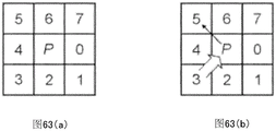
FIG. 63 is a schematic diagram of a clockwise pixel search for a black object on a white background, according to some embodiments of the invention.
FIG. 64 is a schematic diagram of identifying black objects on a white background, according to some embodiments of the invention.
FIG. 65 is a schematic illustration of a molten puddle being detected via a connection assembly marker in accordance with some embodiments of the present invention.
FIG. 66a is a schematic illustration of a comparative image of powder flowing smoothly into a melt pool, according to some embodiments of the invention.
FIG. 66b is a schematic illustration of a comparative image of powder agglomerated in front of the melt due to low laser power, according to some embodiments of the invention.
Fig. 67 is a schematic of a thermal model of simplified lumped capacitance of SLE processing according to some embodiments of the invention.
Fig. 68 is a schematic of the step response of a SLE process with 450 rescanning at a laser power of 450W, according to some embodiments of the present invention.
FIG. 69 is a comparative schematic of simulated transfer function outputs according to some embodiments of the invention.
Fig. 70 is a schematic diagram of a PI control scheme according to some embodiments of the invention.
FIG. 71 is a schematic diagram of a step response of applying a PI controller to a transfer function according to some embodiments of the invention.
Fig. 72 is a schematic illustration of an OSAAC protocol according to some embodiments of the invention.
FIG. 73 is a schematic diagram of an example of a pseudo-random binary signal at about 5Hz for determining the bandwidth requirements of a system, according to some embodiments of the invention.
FIG. 74a is an image of a Ren-80 sample run with laser images of different frequencies with a pseudo-random signal of about 5Hz, according to some embodiments of the invention.
FIG. 74b is an image of a Ren-80 sample run with laser images of different frequencies with a pseudo-random signal of about 20Hz, according to some embodiments of the invention.
FIG. 74c is an image of a Ren-80 sample run with laser images of different frequencies with a pseudo-random signal of about 30Hz, according to some embodiments of the invention.
Fig. 75 is a schematic illustration of a PI test run, according to some embodiments of the invention.
FIG. 76 is a schematic of another PI test run, according to some embodiments of the invention.
Fig. 77 is a diagram of a smoke evacuation system, according to some embodiments of the invention.
Figure 78 is a photomicrograph of a sample of a run with a smoke evacuation system according to some embodiments of the invention.
FIG. 79 is a graphical representation of a measured temperature profile in an open loop test of a smoke evacuation system, according to some embodiments of the inventions.
FIG. 80 is a schematic diagram illustrating curve parameter adaptation under significant system excitation, according to some embodiments of the invention.
Fig. 81 is a photomicrograph of a sample run at a constant reference temperature of 1575 ℃, according to some embodiments of the invention.
FIG. 82 is a graphical representation of temperature profiles measured for experiments with a constant reference temperature of 1575 ℃ with an average error of 2.15 ℃, in accordance with some embodiments of the invention.
Fig. 83 is a photomicrograph of a sample run at a constant reference temperature of 1650 ℃, according to some embodiments of the invention.
FIG. 84 is a graph illustrating the temperature distribution measured for a test with a constant reference temperature of 1650 ℃ and an average error of 5.80 ℃ in accordance with some embodiments of the invention.
FIG. 85 is a graphical representation of a temperature profile measured for an experiment in which the baseline temperature was decreased from 1650 ℃ to 1500 ℃ with an average error of 8.73 ℃, according to some embodiments of the invention.
FIG. 86 is a photomicrograph of a sample run at a step where the baseline temperature is increased in the second half from 1600 ℃ to 1700 ℃, according to some embodiments of the invention.
FIG. 87 is a graph showing the temperature distribution measured for an experiment in which the baseline temperature was raised from 1600 deg.C to 1700 deg.C with an average error of-16.66 deg.C, according to some embodiments of the present invention.
Fig. 88 is a process flow diagram for utilizing parameter development of SLE on new alloys or geometries, in accordance with some embodiments of the present invention.
Fig. 89 is a two-dimensional schematic of the scanning laser epitaxy problem, according to some embodiments of the invention.
Fig. 90a is a schematic diagram of an analytical simulation, according to some embodiments of the invention.
FIG. 90b is a schematic diagram of a COMSOL simulation, according to some embodiments of the present invention.
Detailed Description
Particular embodiments of the present invention relate generally to additive manufacturing and repair techniques, and more particularly to a system and method for manufacturing and repairing parts using Selective Laser Sintering (SLS) and Scanning Laser Epitaxy (SLE). The system may include a high power laser, a high precision control system, and a powder material that can be melted and solidified in place. The system may be used to repair parts that have broken, eroded or damaged, for example, during use. The system can also be used to manufacture entire parts from powder stock. The system may also be used to add material in the form of melted or re-solidified powder material to a solid part to make an entire part.
For simplicity and clarity of illustration, the system is described below as a system for manufacturing and repairing turbine blades for jet turbine engines. Those skilled in the art will recognize that the invention is not so limited. The system may be used to repair various parts made from materials that can be melted and re-solidified. The system can also be used to make parts in these materials.
The materials described hereinafter as constituting the various elements of the invention are intended to be illustrative and not limiting. Many suitable materials that can perform the same or similar functions as the materials described herein are included within the scope of the present invention. Other materials not described herein, such as those developed after the development of the present invention, may be included, but are not limited to. Any dimensions listed in the various figures are for purposes of illustration only and are not limiting. Other dimensions and proportions are also within the scope of the invention.
As mentioned above, one problem with conventional manufacturing techniques is that they are both wasteful and time consuming. Conventional subtractive techniques, such as numerically controlled milling machines, can provide precision machining, but result in high material costs due to the material removed during machining. On the other hand, conventional additive technology tends to produce end products with voids or other defects that degrade the quality of the end product. In addition, conventional methods cannot operate at the temperatures and other environmental factors required for advanced materials, such as nickel-based superalloys.
In another aspect, embodiments of the present invention relate to direct selective laser sintering (direct SLS), which is a direct SFF technique. Direct SLS is a laser based rapid manufacturing technique that produces functional, fully dense metal and ceramic parts by direct, layer-by-layer consolidation of constituent powders. In direct SLS, a high energy laser beam can directly cure high density (> 80%) direct cure metal or ceramic powders to high density (> 80%) with little or no post processing requirements. Direct SLS is also an adhesive-free process, as compared to "indirect SLS". Direct SLS also does not resemble "indirect SLS" which involves post-treatment steps of oven degreasing and infiltration. Compared to conventional bulk metal block forming processes (e.g., casting or forging); direct SLS does not require the use of pattern patterns, tools or molds. Metal powders processed by direct SLS are directly subjected to transformation of shape and properties into a final product, into a final product that may require minimal post processing, such as finishing.
Several processing requirements for direct SLS of metals are different from SLS of polymers or polymer coated powders. An important distinguishing feature is the high temperature regime of direct SLS involving metals. At the processing temperatures required for the metal of interest (typically >1000 ℃), for example, the reactivity of the melt poses serious process control problems. Controlling the process atmosphere is very important because it can be successfully built up layer by layer, and also solves safety issues. In the embodiment discussed below, referred to as SLS/HIP, the SLS process may be performed under vacuum to ensure full densification of the can shape during the HIP post-processing.
In the past, there has been no direct SLS study of high performance materials such as, but not limited to, nickel and cobalt-based superalloys, superalloy cermets, titanium-based alloys, and monolithic high temperature metals such as molybdenum. These materials are often used for high performance components, often in high operating temperatures, high stresses, and severe oxidizing or corrosive environments. Direct SLS with the ability to produce parts in such materials is particularly useful in production functional prototypes, low volume or "unique" production runs. For example, to manufacture a typical prototype batch of 100 superalloy cermet abrasive turbine blade tips, direct SLS may save 80% of the cost to achieve acceptable microstructure and performance over conventional methods.
Embodiments of the present invention may also include a hybrid web manufacturing process known as selective laser sintering/hot isostatic pressing (SLS/HIP) that takes advantage of the free forming capability of SLS in combination with the sufficient densification capability of HIP to rapidly produce complex shaped metal parts. The SLS/HIP is obviously faster, lower in cost and high in automation degree, and can flexibly replace the conventional powder metallurgy and HIP process of small-batch or 'unique' high-performance parts adopted by the current navigation and aerospace national defense departments.
Embodiments of the invention can also include Scanning Laser Epitaxy (SLE). SLE is a new direct digital fabrication (DDM) technology that uses an incremental layered system to fabricate three-dimensional nickel-based superalloy components. The system can fabricate functionally graded materials with specific microstructures and other properties to form Heterogeneous Multifunctional Components (HMCs). Due to the extreme temperatures and pressures within turbine engines, HMCs are commonly used in engine parts in the aerospace industry. For example, turbine blades are a critical part of engines for extracting energy from the high temperature, high pressure environment generated by combustors, and are the focus of current SLE technology. Turbine blades typically utilize advanced nickel-based superalloys, which are materials capable of withstanding high loads at high temperatures and pressures. The blade includes a complex geometry to cool the blade by incorporating gas flow, and an advanced microstructure that increases the load that the superalloy can carry during operation. SLE fabrication techniques can work with these high-grade alloys, conform to the shape of the part and extend the existing microstructure into the repair section.
SLE can also be used to fabricate a three-dimensional object by establishing a monolayer deposition. The underlying substrate may be, for example, an initial wafer sheet or a previously created layer, which is covered with metal powder prior to processing. Each layer may be melted and resolidified with a highly focused laser of a portion of the metal powder and its underlying substrate to extend any underlying microstructure to newly developed portions, as shown below.
As shown in fig. 1a-1c, one significant application in the SLE process is in the aerospace industry for the manufacture and repair of turbine blades. The final blade may include a plurality of microstructures throughout its volume, including single crystals (SX), columnar crystals, and equiaxed crystals. By reflowing a small portion of the substrate, the microstructure used in the previous portion of the turbine blade may be expanded to a new region. This is particularly important for single crystal components, since it allows new materials to be made without the need for grain boundaries. This requirement has hitherto been that the SX material be marked as unweldable. The method also alleviates other problems such as the occurrence of heat checking and cracking in other repair techniques.
In some embodiments, an energy source 105, such as a laser, may be used to melt the metal powder 115 to form a new layer of material 110 having the same properties as the underlying material 125. For example, for a turbine blade 125, the system can produce the layer 110 while maintaining, for example, a single crystalline structure. In other embodiments, the system may utilize the laser 105 to fabricate the multilayer component 135 from the metal powder 115. In both cases, the melt pool 120 may be tightly controlled to provide the material with desired properties (e.g., single crystal). In some embodiments, a particular microstructure 130 may be controlled and formed, such as, but not limited to, an equiaxed, columnar, or single crystal structure.
Optimization of SLE for a new metal alloy requires optimization of its three main settings: laser power, laser scan speed and the number of repeated scans at the initial edge of the sample to create a melt pool. These three settings establish a stable melt pool and temperature gradient to form effective seeds in the newly placed material and to grow any microstructure desired. The three areas of study involved in achieving microstructure control are flow modeling, proper control of part fabrication, and characterization of the fabricated parts.
By creating a model system, for example, the number of experimental runs required to find the ideal set of parts is reduced. This in turn reduces material costs while increasing efficiency. When a part is manufactured, advanced control systems are used to accurately distribute the heat in each layer, while also allowing the process the ability to perform real-time maintenance to maintain the sample with specific parameters. The microstructure of each part manufactured can then be analyzed to determine what has happened at a particular run-time setting and to improve the settings for the final product.
Embodiments of the present invention are directed to improved microstructure analysis by using a program that tracks various features found in samples manufactured by SLE technology and a design of experiments (DOE) program to gain insight into how SLE settings affect microstructure. For example, the system may use optical micrographs and may be quickly accomplished using a typical laboratory computer using Matlab or other suitable software. This can create an automated system for identifying ideal parameters, bridging low-end microstructure tracking run by eye or basic feature recognition programs, and more time-consuming and expensive techniques such as EBSD. Using this intermediate microstructure tracking and analysis program can be used to find the best settings for each new material, microstructure layer, deposition height, sample size. This procedure also enables SLE technology for casting repair.
Conventional programs are not designed to distinguish between different manufacturing techniques. For example, EBSD provides specific details of crystal orientation throughout the sample, but does not distinguish between cast and laser machined regions. Creating a custom microstructure analysis program for SLE allows for the selection of process parameters that take into account features that have never been considered before. It may also contain every useful sample due to the fast implementation of the system. This ability can help to better understand SLE process parameters versus microstructure.
As mentioned above, the initial application of SLE is to repair damaged and worn turbine blades. The turbine blades used in an engine have hundreds of blades and are critical to its efficiency. However, after a long period of use, the edges of the turbine blades located near the inner wall of the engine begin to deteriorate. After the turbine tip wears down as little as 1mm, the efficiency of the engine drops dramatically because excess air can now bypass the turbine blades through the worn out portion.
Typically, worn turbine blades are not repaired but replaced with new blades. However, this has a tremendous impact on the operating cost of the engine, as one blade can cost hundreds to tens of thousands of dollars. The average life expectancy of a turbine blade is about three or five million miles of flight, but each blade must be periodically checked for earlier failure. Turbine blade tip repair is a promising alternative and is seeking to replace current replacement solutions with a lower cost alternative.
Several processes have been developed for repairing damaged turbine blades, but all suffer from significant problems. Selective Laser Melting (SLM), Direct Metal Laser Sintering (DMLS), and Shape Deformation Manufacturing (SDM) tend to have similar drawbacks in their repair work. Excessive melt-back depth and warpage can lead to delamination and cracking of layers in the sample. For example, if the melt viscosity is too high during processing, spherulites may be created in the laser interaction region, known as the spherulization effect. During the curing of the sample, heat checks will occur if the stress induced by shrinkage does not account for the elastic and plastic deformation of the material.
The level of microstructure control and formation is also problematic in competing repair technologies. For example, nickel-based superalloys have shown strong susceptibility to heterograin formation during manufacturing, particularly when using SLM-like processes. Unlike the SLE process, the fabrication techniques described above also do not extend the single crystal microstructure.
None of the SLE processes found or greatly reduced the problems that occurred in SLM, DMLS and SDM when using greatly optimized parameters for each specific material. Reducing these problematic features while creating the desired microstructure in the part can be achieved by finding the optimal SLE setting for each alloy. As mentioned above, the three important variables that can be controlled in the process are the laser power, the laser scan speed, and the number of initial repeat scans.
A series of experiments can be performed to find the best setting for each new material. For each experiment, metallographic images can be used to assess several broad microstructural features and problematic features. The underlying trends can be found primarily by visual comparison and intuition. After suspicious trends have been found for each parameter and approximate regions of interest have been located, several DOEs can be performed to find the optimal settings. Using the simple parameter measurements described above, the DOE can be performed to find trends and optimal variable values to create quality and repeatability.
Using digital optical micrographs that can be created quickly and periodically for each experimental run, a complete understanding of the microstructure can be found and exploited. Using a custom quantitative metallographic procedure, each microstructure detail required can be identified, isolated and recorded. Using this trace data for each available segment, and the corresponding SLE settings, statistical analysis and program optimization can be performed. Statistical methods can provide ready comparisons between samples to see trends and relationships. The inclusion of a sequence analysis DOE program can save expensive materials and processing time while providing relevant data to create a best fit piecewise relational equation between the SLE parameter and each measured response.
Today's manufacturers of turbine engines, such as high performance jet and power generation system manufacturers, strive to increase engine efficiency and reduce costs. Increasing the operating temperature of a turbine engine may improve efficiency, but this is limited by the nature of the materials used in the engine. Today's high temperature components of turbine engines can reach temperatures above 1200 ℃, and available materials are limited to those that exhibit creep and fatigue resistance at high temperatures. Nickel-based superalloys are one of these materials and are currently the most common material used for high temperature parts of high performance jet aircraft. Although these nickel superalloys perform well, they still reach the limits of performance.
To further increase the strength and durability of turbine components, these nickel superalloys are now cast with a particular microstructure morphology that better withstands extreme operating conditions. As shown in fig. 2a-2c, three microstructural morphologies generally occur in turbine castings: polycrystalline or equiaxed, directionally solidified, and single crystalline. Turbine castings of polycrystalline morphology tend to be prone to failure because they contain some grain boundaries that are transverse to the longitudinal direction of the blade or the principal axis of stress. Directionally solidified blades, on the other hand, have grain boundaries in only a single direction perpendicular to the main axis of stress, making the blade more durable. Finally, single crystal, or amorphous, components do not contain grain boundaries and are most desirable because they do not require grain boundary strengthening alloy components such as boron and carbon. These components would otherwise be necessary, and these components would not be needed, since they would lower the melting point of the alloy, adversely affecting the fatigue life of the component.
Despite casting with advanced single crystal microstructures, the operating life of turbine blades is still limited, in part, due to loss of tip material due to wear between the blade and the engine casing. Once a blade experiences a certain amount of material loss, typically 0.5-1mm on a blade 8cm tall, it must be scrapped and replaced. Due to the difficulty in casting SX components, replacing each of these blades becomes quite expensive. Therefore, there is a great need to repair and refurbish these blades so that they can be replaced in the engine.
Currently, there is no effective method of repairing turbine blades that have been cast with a directionally solidified or single crystal morphology, as these alloys are considered "non-weldable" or "non-connectable". Although many processes, such as laser engineered net shape fabrication (LENS) and various welding operations, have been attempted, each process has problems with the formation of cracks or the growth of stray crystals.
LENS and Epitaxial Laser Metal Forming (ELMF) are two similar cladding processes that have been applied to repair cracks formed on the platform of turbine blades. In both processes, a high power laser is focused onto the sample and forms a melt pool. Metal powder is then blown into the melt pool at the focal point of the laser and a deposit is created with the raster scan pattern of the laser. This repair method is often plagued by crack formation, equiaxed grain formation, and grain proliferation due to the separation of the dendrite arms from their main dendrites by remelting. Weld-based repair processes have also been susceptible to similar problems, such as cracking and formation of stray crystals. Presumably, these problems can be avoided or minimized by extending the working range over which the scan is performed.
In contrast, the SLE process can be run at much higher scan speeds because the laser scanning can be performed using a set of high-speed galvanometer scanners, and the SLE process is not mechanically connected to or hindered by any powder blowing mechanism. In addition, the pre-positioned powder bed used in the SLE process eliminates any bath disturbance due to the use of powder blow mechanisms during cladding, removing another potential cause of poor microstructure formation. The SLE process also avoids the problems of hot cracking and liquation cracking found when using similar processes for some materials that were previously considered "non-weldable" and "non-joinable".
The high resolution scan pitch used in the SLE process can cause each subsequent raster scan to partially overlap both the preceding and following raster scans, resulting in pre-heating and post-heat treatment during the scan operation. This in turn can eliminate any thermal cracking that occurs in other processes. The high resolution scan pitch also allows finer grain structure to develop in the deposit formed by SLE, which exposes a large boundary region and limits stress that would otherwise lead to liquification cracking. These features of SLE suggest its use with materials such as, but not limited to, Rene-80, which is highly susceptible to liquid cracking and strain age cracking and was previously considered to be unweldable. Further real-time control of the temperature gradients present in the process can only be used to further improve the SLE process and limit the surface tension driven instabilities that lead to many of these thermal and other cracking phenomena.
Another advantage of the SLE process is the ability to create functionally graded microstructures. Many applications of turbine parts having functionally graded microstructures are known. One example is a turbine disk made from a superalloy composition having an equiaxed grain structure with radially increasing grain size. Smaller grains inside the disc provide better tensile properties, while larger grains towards the outside provide better resistance to fatigue and creep. Typically, such components require extensive and long processing steps and lengthy heat treatment times to produce a functionally graded microstructure. In contrast, SLE enables these components to be produced in one processing step, while also achieving complex internal features due to layer-by-layer processing.
Fig. 3 and 4 show an aircraft 10 including an aircraft flight propulsion engine 11. It should be understood that the aircraft referred to herein are generic and include helicopters, tactical fighters, trainers, bombers and other related devices. In addition, other applications for turbine engines include, but are not limited to, power plants, marine vessels, and motor vehicles.
As shown, the flight propulsion engine 11 includes a compressor 12, a combustor 13, and a power turbine 14. Those skilled in the art will recognize that there are many ways to connect the components together. An intercooler may be added to the additional compressor and turbine, connected between the compressor and a reheat combustor that may be added between the turbines. Furthermore, gas turbine engines are also suitable for industrial applications. Historically, industrial gas turbine engines have found widespread use in, for example, natural gas pumping equipment and oil transmission lines, power generation and ship propulsion.
FIG. 5 illustrates a partial enlarged view of the gas turbine engine 11. The gas turbine engine 11 has a rotor disk 17 on which a plurality of turbine blades 16 are mounted and coupled to a shaft (not shown) within the gas turbine engine 11. The plurality of turbine blades 16a form a nozzle within the gas turbine engine for directing a flow of working fluid relative to the blades 16. In some cases, the working fluid is air drawn from the compressor 12.
Fig. 5 also shows a portion of the working fluid seal system 20. The sealing system 20 is designed to reduce leakage of the working fluid and the surrounding working fluid path. The efficiency of a gas turbine engine depends to a large extent on the ability to control and reduce leakage of such working fluid. Thus, the clearance between the tips 19 of the turbine blades 16 and the stationary structure 22 of the gas turbine engine facilitates controlling the bypass of the rotor 17 and the turbine blades 16 by the working fluid. The clearance between the rotating and stationary components (21 and 23, respectively) varies with the expansion and contraction of the components due to thermal cycling that occurs in the gas turbine engine.
The sealing system 20 may include two respective components that form the actual seal between the rotating and stationary components. The two components are an abrasive component 21 coupled to the turbine blade 16, and a fixed wear component 23 coupled to the fixed component 22, the fixed wear component 23 generally involving a shroud and a member that surrounds the rotor disk 17 and the blade 16 while covering a portion of the fixed component 22.
The turbine blade 16 and abrasive member 21 are rotated relative to the wear member 23 to form a virtual seal path in the form of wear on the wear member 23. Rotation of the rotor disk 17 with the turbine blades 16 coupled thereto causes the abrasive component 21 to abrade the wear-resistant component 23 in the absence of a gap between the various components. A particular aspect of the abrasive member 21 is the ability to withstand repeated and violent encounters with the wear member 23 with only minimal loss of material from the abrasive member 21 and preferential wear of the wear member 23. Thus, when the radial clearance of the frictional interface between the assemblies 21 and 23 has disappeared, the abrasive member 21 cuts the wear member 23 to maintain a minimum clearance from each other. The wear of the rotating abrasive component 21 against the wear component 23 creates a fluid path between the rotating components. In one form of the invention, the wear part 23 is a semi-porous wear resistant ceramic well known to those skilled in the art.
FIG. 6 depicts an exemplary turbine blade 16. The turbine blade 16 may be a forged or cast structure. The gas turbine blade 16 may be a monolithic cast alloy structure made, for example, by a precision casting process using various superalloy compositions. Various types of nickel, titanium and cobalt superalloy compositions and manufacturers of such compositions are well known to those skilled in the art. Most superalloy compositions of interest are complex mixtures such as, but not limited to, mixtures of titanium, tin, vanadium, aluminum, molybdenum, silicon, neodymium, nickel, cobalt, chromium, aluminum, titanium, iron, tungsten, tantalum, rhenium, and other selectable elements. Some exemplary materials are known by trade names CMSX-3, CMSX-4, and MARM-247.
Of course, the application of embodiments of the present invention is not intended to be limited to the materials described above, and it may be used with other materials. U.S. patent No. 5295530 to oconna, which is incorporated herein by reference, discloses techniques for producing integrally cast turbine blades 16 having an equiaxed, directionally solidified, or single crystal alloy structure. Gas turbine blades and vanes are commonly referred to as airfoils.
The abrasive component 21 may be metallurgically bonded to the blade 16 without the use of brazing elements or other low melting temperature joining materials. Elimination of the low melting point brazing elements produces a braze-free cermet having extended oxidation life and the ability to withstand exposure to higher operating temperatures than components having brazed elements. The abrasive component 21 comprises an abrasive cermet composition and may include a metal powder superalloy matrix bonded with ceramic abrasive particles. In some embodiments, the ceramic abrasive particles may be coated with an active material. In other embodiments, the ceramic abrasive particles are not coated with an active material.
In some embodiments, the abrasive component 21 may comprise about 0 wt% to about 50.0 wt% active metal coated ceramic abrasive particles and about 50.0 wt% to about 100.0 wt% superalloy. The ceramic abrasive particles may include a ceramic abrasive particulate material, which may include, for example and without limitation, one or more of the following: cubic boron nitride, synthetic diamond, silicon carbide and alumina, or combinations thereof. In some embodiments, the ceramic abrasive particles can have a particle size in a size range between 80 mesh and 120 mesh. Of course, other particle sizes and ceramic abrasive materials are also contemplated herein.
The active material may be, for example, titanium, which wets the surface of the ceramic abrasive coating to promote metallurgical bonding between the particles and the metal matrix. The titanium coating may be applied using, for example, a fluidized bed chemical vapor deposition technique to ensure uniformity of the coating on the particles. Of course, other suitable methods known in the art are also acceptable. The ceramic abrasive particles may be uniform or graded in any portion thereof.
In some embodiments, the bed forming the abrasive component 21 may withstand direct laser machining that melts, solidifies, and bonds the metal matrix material to the turbine blade 16. Direct laser machining is a manufacturing technique that produces parts in a powder bed, and the details of direct laser machining involved in manufacturing the abrasive tip of the blade 16 are as follows. This method is applicable to the entire area of the material, selected areas of the material, and cut portions of the part. The blade tip with abrasive component 21, after direct laser machining, produces many prior art-induced free components with degraded life that include the addition of melting point suppressants that often occur in brazing alloys and/or in thermal cycles that require diffusion bonding that expose the component to high temperature brazing and/or morphology of degradable strengthening phases.
FIG. 7 illustrates another gas turbine engine blade 160 having an abrasive cermet member 210 operatively coupled thereto by a secondary connection. The secondary joining operation is typically a brazing operation that couples abrasive component 210 to blade 16 using brazing material 211. In some embodiments, the abrasive component 210 can be manufactured by direct laser machining for manufacturing the abrasive component 21. The abrasive component 210 may thereafter be attached to the blade 160 via the brazing material 211.
Fig. 8 shows a device 25 for direct laser machining of a powder bed of material to produce a free-form fabrication. The term "free-form fabrication" as used herein includes, unless otherwise specified, the ability to fabricate solid parts and/or hollow parts. The apparatus 25 includes a chamber 26 in which direct laser machining is performed and a laser 28 for melting material which is then solidified.
In some embodiments, the chamber 26 may be a fluid pressure vessel to which is connected a vacuum extraction system 27 for changing the atmosphere in the chamber, and a heat source capable of heating the material powder bed 30 (fig. 9) to an elevated temperature. Preheating the bed of powder material 30 prior to laser beam melting and solidification aids in outgassing of the material and improves surface characteristics, wetting and flow and other properties. The chamber 26 is designed and constructed to maintain a high purity atmosphere of the selected gas. The heat source may be located inside or outside the chamber 26 and may precisely heat the powder bed and control its temperature in a range from ambient temperature to about 2000 degrees celsius. The vacuum source is preferably capable of providing a high degree of vacuum.
In some embodiments, laser melting and solidification of the material may occur when the bed is at an elevated temperature, thereby improving dimensional stability. In one embodiment, a temperature approximately in the range of 500 degrees celsius to 750 degrees celsius may be used for the material bed during the direct laser machining melting and solidification stage. In another embodimentDuring laser machining, the material bed may use temperatures above 750 degrees celsius. In some embodiments, the vacuum may be at about 5x10 -3 Ask to 1x10 -7 In the range of torr, preferably about 5x10 -5 . 1x10⁻⁷ torr. However, other pressures are also contemplated by the present invention.
In some embodiments, chamber 26 may be considered to be similar to a vacuum furnace that may be adjusted to provide a tightly controlled atmosphere within the chamber. The control of the atmosphere is characterized by the ability to adjust the chemical composition, vacuum and temperature of the gases in the chamber. In other embodiments, an inert atmosphere may be used to inhibit volatilization of the material components within the chamber 26.
The laser 28 may provide a beam that selectively melts and resolidifies material within the chamber 26. Other means for melting materials contemplated herein include, but are not limited to, ultrasonic, X-ray, and microwave. In some embodiments, chamber 216 may have a laser transparent window 29 sealed to allow the laser beam to pass therethrough. In other embodiments, the system may include a disposable or indexable laser transmission window arrangement to compensate for window clouding and deposits. Thereby allowing it to return to a more fully transparent laser transmission window to facilitate process control and reproducibility. The means for melting the material may be confined within the chamber 26, which may be an external chamber and may be conveyed through an opening in the chamber and/or by a medium connected to the chamber, such as a fiber optic cable.
Fig. 9 shows the chamber 26 partially removed for clarity. Disposed within the chamber 26 may be a bed 30 of material powder for melting with a laser beam, as shown. The material holder 31 is shown as a tray, however, other types of material holders are also contemplated herein. In some embodiments, for example, the material holder may hold a turbine blade so that the abrasive cermet composite may be melted, solidified, and bonded directly to the blade (i.e., the blade tip is fabricated directly on the blade). In some embodiments, the material powder bed 30 is not integrated with the material holder 31. In other embodiments, the holder is provided with a member to which the bed of material powder can be bonded. In still other embodiments, the powder bed may be directly integrated with the material holder.
In some embodiments, the system may maintain different inclinations of components (such as tools, blades, etc.) in order to position the components in the chamber 26 for local repair. Repair of the component may include, for example, locally heating the component to room temperature or near room temperature. The localized heating may be performed by, for example, but not limited to, induction heating, electron beam, laser, plasma, and/or focused lamp. The material holder of the present invention may be designed to withstand the pre-heat temperatures that the powder bed 30 can withstand.
Fig. 10 depicts a laser 28 and means for controlling it. In some embodiments, Nd: YAG laser. Both single pass melt thickness and dual pass melt thickness beds are contemplated herein. However, other types of lasers and different power levels are within contemplation of the present invention. In some embodiments, a 250 watt laser may be used. Control of the laser is considered to be within the purview of one skilled in the art and the particular laser apparatus control schemes disclosed herein are not intended to limit the present method and apparatus for manufacturing parts by direct laser machining.
The components of the laser system are integrated into laser head 28 as shown in fig. 10. Laser head 28 may include such conventional control elements as described in U.S. patent nos. 4,863,538 and 5,156,697. Such as a safety shutter, front mirror assembly, and focusing elements such as diverging and converging lenses. A computer 31 and scanning system 32 may also be included for controlling the direction of the laser beam as it impinges on the powder bed 30. In some embodiments, computer 31 may include a microprocessor for controlling laser 28 and a CAD/CAM system for generating data for defining part dimensions. Of course, other methods of generating data defining dimensions of a part are also contemplated herein. In some embodiments, the laser scanning position and scanning speed may be controlled by computer software.
Fig. 11 depicts a top view of a pair of abrasive cermet parts 21 formed in the powder bed 30. The abrasive cermet 30 may be formed by a direct laser process of the internal material, with the powder bed 30 coupled to the turbine blade 16.
Fig. 12 shows an enlarged view of a laser beam scanning sequence. The laser scan sequence may vary because, among other things, the geometry and scan order of the part affects the thermal profile of the part. In some embodiments, the pattern may be selected to provide a uniform heat distribution. One way to achieve uniform thermal distribution is to select the appropriate laser scan speed, scan spacing, and laser beam energy for each scan length vector. The scan length vector may be defined, for example, as the portion of the part that can withstand a particular pass of the laser beam. In some embodiments, the scan pitch may be less than 0.100 inches. In other embodiments, the scan pitch may be in the range of about 0.0001 inches to 0.0003 inches.
Table 1 contains the scan pitches used to produce abrasive ceramic parts in direct laser machining. It will be appreciated that fig. 12 is merely illustrative and is not meant to limit, for example, the geometry, scan spacing, beam diameter, etc. in any way. The material powder bed 30 becomes the target surface for the laser beam during direct laser machining.
In some embodiments, the component made of the abrasive cermet material may be less than about four inches in diameter and less than about 0.100 inches thick. In other embodiments, the thickness of the component made of the abrasive cermet material may be in the range of about 0.035 to 0.060 inches. In some embodiments, the component made of the abrasive cermet material has a thickness of about 0.060 inches. Monolithic metal components having a diameter dimension of less than four inches and a thickness of up to four inches are also contemplated herein. In some embodiments, the monolithic metal part may be greater than 0.100 inches thick and may be manufactured by melting a first powder bed and thereafter melting additional layers placed on the first layer of powder. In some embodiments, the single piece metal part may have a thickness of about 0.100 inches. In some embodiments, the component formed by direct laser machining may have a layered structure.
Fig. 13a and 13b illustrate the melting and solidification of the abrasive cermet composite of the metal matrix composition 75. The laser beam can melt the metal matrix mixture to obtain the proper flow rate from the molten material. A suitable flow rate may be qualitatively defined as, for example, the flow rate required to eliminate blowholes, maintain high dimensional accuracy while producing high density parts, and reduce tearing. The control of the flow rate depends on many parameters including, but not limited to, the atmosphere in which melting and solidification occurs, the degree of preheating of the raw powder bed, and characteristics that affect the energy density of the laser, such as laser power, scan spacing, and scan speed.
In some embodiments, a very small scan pitch and high scan speed can be used to maintain uniform thermal distribution. The selection of the scan speed and scan pitch has a direct effect on the surface roughness of the resulting part. The fine scan pitch, for example, will provide a relatively uniform smooth surface, while the scan speed, which affects surface roughness, is largely dependent on the total energy density and associated residence time in the region of the molten material. For a given material, high scan speeds with high energy densities that produce long melt dwells can produce poor surface finishes. On the other hand, the same scan speed with lower energy density can produce a better surface finish. In some embodiments, fine scan pitch can be used and laser power and scan speed can be varied to provide different energy densities, resulting in short melt residence times through full layer thickness melting and density. Table 1 provides test data for various embodiments that have produced acceptable results.

TABLE 1
The test data for the cermet composite showed passage of the powder having a particle size of about 1900J/cm 2 To achieve complete full layer thickness melting. A sample of the cermet composite comprised 73.5 wt% metal alloy and 26.5 wt% abrasive grain coating. More preferably, the metal alloy is MarM 247. In some embodiments, the abrasive particle coating may comprise an abrasive grit material having a titanium coating of about 2.5 to 12 wt% forming a uniform coating on all surfaces of the particle. However, at these energy levels (1900 joules/cm) 2 ) The sample shows pores wrapped around sand 76 (see fig. 13a and 13 b). However, 2000 to 4000 joules/cm 2 Energy density in the range of (a) successfully eliminates pores remaining around grit 76 in the superalloy cermet composite material.
In one sample, when the fluence level is about 2500 joules/cm 2 The pores begin to disappear. At 2500 joules/cm 2 At the energy level of (c), the microstructure transforms from a fine equiaxed to dendritic. A very fine grain microstructure, ASTM grain size 10, at from 1900 joules/cm 2 To 2500 joules/cm 2 Produced in the sample to be treated, which can be used in a single piece of metallic material, because ofFor which they exhibit superplasticity at high temperatures. This form of microstructure control allows the production of equiaxed parts, providing more uniform and improved mechanical properties.
The production of the component by direct laser machining can be started together with the mixing of the material components. In some embodiments, the materials may be mixed for 4-6 hours before insertion into the chamber 26. The material may then be pre-heated for a period of time to pre-treat the material. In some embodiments, preheating may occur within chamber 25. The environment within the chamber 26 may then be adjusted and the material bed 30 may be allowed to withstand direct laser machining. In some embodiments, direct laser machining may occur while the material bed 30 is at an elevated temperature to improve dimensional stability. The formed part may have a texture consistent with a metallurgical casting having a fine microstructure. In addition, refinement of the microstructure may be adjusted by changing, for example, but not limited to, the energy density, atmosphere, and preheating of the material bed 30. For example, control of the energy density during this process can achieve region-specific microstructure control, resulting in a part having a variety of microstructures ranging from equiaxed to dendritic. Further, the component may have regions with equiaxed, dendritic, directionally solidified, and/or single crystal.
Direct laser machining is a process in which the material components of a powder bed are melted and solidified directly by a laser to produce a solid part with little or no post-processing. The unmelted components in the direct laser processing procedure are reusable, thereby minimizing the amount of waste and raw material wasted in the process. The resulting assembly is substantially void-free and crack-free and can be manufactured to approximate a net shape. In some embodiments, the microstructure of the component may be modified by post-processing, i.e., heat treatment. Some parameters of the direct laser process can be adjusted to produce highly dense or porous parts as desired. In addition, the process may be used to produce composite components, such as cermet abrasive components and/or full density monolithic metal components.
As shown in FIG. 14, embodiments of the invention may also include methods for repairing and forming parts using powdered materials and a directed energy source (e.g., a laser). Many variations involving pre-processing and processing steps may be employed to optimize the results.
The directed energy source can be any commercially acceptable laser capable of melting various metal powders with or without preheating the powder bed. As mentioned above, such devices may also include a scan control that is capable of tracking a set scan path. In some embodiments, the laser may be capable of melting various metal powders without preheating the powder bed. A specific example of a laser for use in the present invention is a 250 watt Continuous Wave (CW) Nd: YAG laser with 6 mm beam diameter (1/c) 2 ) 18mard divergence angle and 1.06 μm wavelength. In some embodiments, the beam diameter may be about 100-500 μm. Preferably, the powder used in the system and method may comprise particles of substantially the same size and sphericity and free of any internal porosity. Although this is not essential, it is well known and available that materials meet these requirements. Powders made of smaller particles (i.e., about 10-100 μm) are preferred, but the particle size may vary depending on the specifications of the part to be built. Suitable particle sizes will be apparent to those skilled in the art.
In pre-processing, embodiments of the present invention may avoid the conventional technique of preheating the powder bed prior to SLS processing. However, preheating may also yield an acceptable product. The preheating temperature may vary depending on the material to be sintered. For example, preheating may be used to bring the temperature of the powder to a point slightly below the melting point of the powder. In some embodiments, the system may be equipped with heating means, for example molybdenum rod elements with temperatures up to about 1000 ℃ may be obtained.
In a further pretreatment, the powder is degassed to improve the results. The powder may be degassed by a static thermal degassing process, for example by heating the powder by radiation in a vessel under vacuum. However, to avoid burning of the powder, a dynamic degassing process may be used, exposing various portions of the powder to the same heat. In some embodiments, this dynamic degassing can be achieved by introducing an inert stirring device in the powder container to uniformly circulate the powder during the degassing process.
In some embodiments, the process atmosphere may be maintained at a relatively high vacuum level-such as about 10 -3 And (4) supporting. Such an atmosphere may produce better results than an inert gas atmosphere, which may contain unacceptable levels of impurities (such as water and oxygen). These impurities may form an oxide film on the sintered layer, which hinders the free flow of the molten material and good bonding with the subsequent sintered layer. Furthermore, for in-situ packaging in SLS/HIP processing, SLS is preferably performed under high vacuum. Such a partial pressure atmosphere may be achieved by evacuating the chamber to a high vacuum level (e.g., 5x 10) -7 To 1X10 -5 Torr), followed by backfilling with an ultra-high purity inert gas such as argon or helium gas of 99.999% purity (e.g.,<2ppm of oxygen, in the presence of oxygen,<a water content of 3ppm by weight,<1ppm of a hydrocarbon and<6ppm nitrogen).
10 -3 The vacuum of the torr also reduces evaporation of alloying elements from the molten pool and condensation of metal vapors on the laser window. To further prevent such condensation, an ultra-high purity (UHP) inert gas such as argon or helium can be used below the laser window after evacuating the chamber to a high vacuum. In some embodiments, this may be achieved by using a double-sided flange between the laser window and the flange of the chamber side window; welding a stainless steel pipe joint at one side of the double-sided flange, and connecting a variable leakage valve to the double-sided flange through the stainless steel pipe joint; and a stainless steel diaphragm gas regulator connected to the inlet side of the leakage valve and mounted on an ultrahigh pressure cylinder via a stainless steel pipe with joints at both ends. Knurling on the leak valve, fine control knob and having 13000: the mechanically advantageous leverage of 1 allows for precise control of the gas flow. Of course, other devices may be used and are contemplated herein.
In some embodiments, the system for controlling the vacuum level of the process atmosphere may include a vapor diffusion pump backed by a mechanical vacuum pump. The system may also include a gate valve that mates with a high conductance 90 degree elbow, which in turn may be fitted to the chamber with a large diameter flange port. In some embodiments, the gate valve may also include a "roughing port". Any interfaces in the system may be shut down to reduce leakage. Furthermore, in some embodiments, all walls of the chamber except for the walls used to direct the powder into the chamber may be fusion welded to minimize the need for O-rings or other seals. To prevent powder from being ejected from the feed and separation side barrels during evacuation of the chamber, the pressure between the chamber void space on the powder bed and the void space below the powder column in the feed and separation side barrels can be equalized. This can be achieved, for example, by connecting the aforementioned void spaces using stainless steel bellows. The rate of evacuation can be controlled, for example, by using a bellows valve mounted at each exhaust port.
An apparatus for feeding powder into the chamber may include a separating and feed side powder column, a powder transport roller, and an associated actuator. To maintain vacuum integrity, stainless steel welded bellows may be used as the shaft for the separation, feed, and roll actuators. To impart rotational motion to the roller, a hollow drive shaft may be used having a concentric shaft coupled to a bevel gear system. For example, one end of the spindle may be connected to the roller via a bevel gear system, and its outer end may be coupled to an MDC direct drive high vacuum rated speed feed-through.
In some embodiments, the flexible shaft may be transferred to the room temperature atmosphere end of the feedthrough by rotational motion from, for example, a dc motor mounted on the frame. The flexible shaft is preferably long enough to provide rotation to the roller shaft via a rotary feedthrough, as the entire roller assembly will reciprocate along the powder bed. In some embodiments, a motor that is small and light enough can prevent the flexible collar from wrapping around itself. This situation may lead to unstable powder transport. In an apparatus for powder delivery, the actuator for providing reciprocating motion to the torque of the roller assembly may comprise a seat adapted to hold when the return drive load is greater than 45N (10 pounds). Such actuators are well known in the art.
The means for transporting the powder may also have an optimized center-to-center distance between the separation and feed cylinders so that the heat flux from the heater to the powder plate is efficient and uniform without sacrificing the efficiency of powder transport. Furthermore, any expansion slots may be present in the powder plate of the means for conveying the powder (to prevent it from bending when the powder plate is heated), which means may comprise baffles or other means for blocking the powder from being transported through those slots. In some embodiments, the baffle may be flexible enough to allow the powder plate to expand without bending as it is heated.
Once the powder is deposited, the laser may be scanned along a predetermined path to selectively fuse the powder into a desired shape. In some embodiments, the laser does not follow the conventional raster scan path as shown in FIG. 15, but instead, the laser may take the form of a continuous vector ("CV") scan (an example of which is shown in FIG. 16) that causes each individual motion segment to occur in any direction, but with the continuous segment as part of a continuous path. In this way, a constant melt pool is maintained under the laser beam. In some embodiments, the scan may follow a parametric curve, such as the Archimedes' spiral shown in FIG. 17, or other path of an arbitrary piecewise parametric curve that fills the cross-section of the region to be fabricated. In some embodiments, the scan path may follow one parametric curve or another arbitrary piecewise parametric curve corresponding to the contour lines of the inner and outer boundaries of the cross-section to be fabricated.
Maintaining a constant melt pool is important to forming a uniform, non-porous product, including maintaining a constant melt pool within the currently scanned layer and constant remelting of a portion of the just-scanned layer. As shown in fig. 18, a typical CV scan path may include a radial spiral scan pattern that begins at a point inside the region to be fully densified where a finite starting radius of the path is defined. In some embodiments, the starting radius may be similar to the beam diameter of the laser to prevent the powder within the radius from being unexposed. In other embodiments, the scan path may be a circular path.
The scan may begin by tracing a circle with the starting radius of the path and then repeating the scan around the starting radius up to 20 times. In doing so, the laser power is increased to the terminal power to create a melt pool at the center while substantially avoiding spheroidization of the laser beam at the initial incident position of the metal powder bed. Further, in some embodiments, the laser beam can oscillate in a path perpendicular to the laser's scan path to impede any melt advance speed that might break the continuity of the solid-liquid interface. In some embodiments, the scan speed may be in the range of about 0.1-10.0 inches/second. The scan spacing between successive revolutions of the CV scan path may be set in the range of about 0.0001-0.020 inches, preferably about 0.0001-0.005 inches.
In some embodiments, the scan pattern used to process the annular region may correspond to the radial scan pattern shown in fig. 19. The nature of the scan path is actually an angle that is acute at points where the lines are actually and functionally parallel, scattering outward (hence the term "radial scan"). After the rotation is complete, an additional overlapping scan of about 25 (preferably about 25.7) may be included to completely melt and resolidify the initial segment of the scan over which the laser power increase occurs. The layer thickness may be about 0.005 inches and the scan spacing between radial lines may be in the range of about 0.0001-0.010 inches, preferably about 0.00015 inches.
In an SLS/HIP process, the top endcap may be processed in the same radial spiral scan pattern as the bottom endcap, followed by a scan pattern of concentric rings (each ring corresponding to the radial scan path shown in fig. 19) of decreasing diameter starting from the outer diameter of the endcap. An overlap of about 50% between successive loops may be used. The accompanying radial scan pattern may help ensure a complete bond and a continuous interface between the tip cap and the underlying skin.
An important aspect of the present invention involves the joining of successive layers on a previous layer. In fusing successive layers, the invention includes a portion of the layers prior to remelting. The process of remelting the previous layer is similar to the dilution or "reflow" step in conventional fusion welding. This reduces or eliminates impurities and oxide films that may have formed on previous layers, thereby improving adhesion between the layers to form a nearly pore-free product. Furthermore, during solidification, grain growth will occur at the solid-liquid interface between the base metal and the liquid with which it is in contact, similar to the epitaxial solidification known from fusion welding. Remelting the base layer causes the epitaxial grains to grow unevenly.
Some alloys (e.g., alloy 625) tend to crack in the axial and planar directions along the end cap/core interface and inside the part in direct SLS. While a significantly increased sintering cycle will reduce such cracking, it also increases time delay and expense. Thus, in some embodiments, the solution to cracking is to reduce the scan pitch, increase the scan speed, and reduce the starting diameter to ensure that a molten pool forms in the center, rather than leaving an unsintered region in the center.
In some embodiments, the metal powder can be placed in a vacuum degassed, room temperature feed side cylinder. The chamber can then be closed and evacuated to about 10 deg.f by mechanical pumping via a roughing port -3 And (7) supporting. At this vacuum level, the roughing port can be closed and the gate valve connecting the chamber to the vapor diffusion pump can be opened. The chamber may then be further evacuated to a high vacuum (preferably about 10 degrees f) -6 Tray). In this regard, a slight depressurization of ultra-high purity inert gas, such as argon or helium, may be introduced into the chamber via a leak valve connected to the chamber by a stainless steel tube. The pressure relief can be adjusted to establish about 10 in the interior of the chamber -3 Dynamic partial pressure of the susceptor while the inert gas is constantly flowing into the chamber and out of the chamber by the diffusion pump.
The piston in the feed cylinder can move up approximately 0.005 inches pushing a powder layer onto the surface of the powder plate. The roller actuator may then move the horizontal, cylindrical, counter-rotating roller through the powder plate. This movement of the roller sweeps across the powder plate and forms a new powder layer that is deposited on the surface of the part cylinder. The laser beam can then be actuated by a galvanometer scanner to scan a pattern over the newly deposited layer of powder under computer control. This scanning pattern ensures that the powder melts to form a fully dense layer of the desired shape and fully bonds to the previously solidified layer of the lower layer. After the scan is complete, the part side piston can be lowered by about 0.005 inches and another layer with fresh powder can be deposited using the procedure described previously. The next layer having the desired shape is then scanned by a laser and the process repeated, building a stack of objects until the complete object has been constructed.
In some embodiments, variations of the present invention may address issues particularly related to metal machining. In laser sintering, a large unwanted downward growth of the new powder layer without the base solid layer can occur. However, by creating a support layer and then "skipping" a layer, the surface oxide film formed on the support layer can act as a well-defined interruption layer, thereby mitigating unwanted growth.
The method begins as described above, where one or more layers are scanned and built up in successive layers. If the shape of the next cross-section to be produced ("second cross-section") is such that it does not lie completely within the inner and outer boundaries of the current cross-section ("first cross-section"), deformation can be performed. In this case, the powder outside the first cross section but to be below the second cross section may be scanned to form a "false layer". During the scanning of the second cross-section, a normal scan lays down a portion of the second cross-section on the first cross-section, remelting a portion of the first cross-section to remove any oxide film, thereby creating a non-porous, uniform product. However, the portion of the second cross-sectional layer that falls outside the boundary of the first cross-sectional layer is scanned so that no part of the first cross-section is re-melted (the scanning parameters, such as scanning speed, scanning pitch and laser power, should be adjusted depending on the scanned material). In this configuration, the underlying oxide film will provide a barrier to prevent any unwanted downward growth.
In post-processing, the part and remaining powder may be placed under vacuum for about 12 hours during which time the processing chamber may be purged to atmospheric pressure with argon or helium. Such "cooling" substantially avoids oxidation of the metal powder and allows any unsintered powder to be reused after collection.
In some embodiments, SLE can also be used to process various superalloys commonly used for turbine blades and other components in the aerospace industry. Each material may require, for example, a different laser power, scanning speed, and/or repeated scanning to produce the desired microstructure. This may result in a large number of experimental runs to screen out the optimal settings. However, due to the high costs associated with materials and components, a set of experiments may also be performed in some simplified form to reestablish conditions of worn turbine blades while reducing costs.
In an initial testing phase of a new alloy, for example, the geometry may be reduced from a complex shape to a similarly sized rectangular test piece 1.25 inches long, 0.27 inches wide, and 0.1 inches thick made of the same material as the turbine blade. This allows for lower sample manufacturing costs, such as simplified conditions and faster processing. As a better identified optimal operating parameter, the geometry may be modified in two steps to a more turbine blade-like design, as shown in FIG. 20. After the rectangular precipitation is finished, the waveform precipitation can be carried out on the rectangular test piece. Then, an airfoil design may be created on a rectangular test piece, and finally on an airfoil test piece.
Because the turbine blade is much larger than the sample specimen, the heat sink can be used to properly simulate the heat transfer that would occur when repairing an actual blade. A inconel 625 substrate 2105 may be used that includes five evenly spaced coupons 2110 (of course, the number of coupons is arbitrary). There may be one through hole 2115 in each well region where the test piece is located, which simulates the hollow space under the tip cap of a typical internally cooled turbine blade, resulting in a more simulated heat distribution during processing.
In each experiment, the sample specimen was thoroughly cleaned to remove any possible impurities in the process. They may then be provided in a 625 inconel substrate. A holding container may then be placed over the sample and mounted to base 2105 to maintain the powder at the desired height. Using the previously measured packing densities of the different powders, the exact amount of powder used can be weighed out and then the powder can be metered and added uniformly into each cavity. This process is illustrated by fig. 21, with the rightmost cavity left empty, the middle cavity containing the sample, and the leftmost cavity containing the sample and powder.
In this configuration, each baseplate 2105 can accommodate five specimens and a total of four baseplates are available for the current experimental specimens, providing twenty specimens that can be tested in one operation. Each base plate 2105 may be screwed to a different aluminum dummy plate, each measuring 10 square inches inserted to place them on a rail system. Of course, the mechanical arrangement may be different without departing from the spirit of the invention.
The samples may then be placed in a controlled atmosphere processing chamber where they may be inserted into a track made of 80/20 extruded aluminum. The chamber may then be purged with an inert gas for processing. Once the complete set of five samples has been processed on the substrate, the next mock plate may be moved along the track to the exact operating position. A 1kW fiber laser as shown in fig. 22a can be used in conjunction with a galvanometer scanner during the process to establish and move the molten pool through a sample as shown in fig. 22 b.
During operation, at least three instruments may be used to collect data: thermal imaging cameras, video microscopes, and laser machining machine vision cameras. As shown in fig. 23, the instrument is shown mounted in an atmospheric chamber. Among other things, a thermal imaging camera may be used to measure the temperature field of the sample during operation. This information can be used to provide data that can be controlled in real time to maintain a desired temperature field to achieve a desired microstructure. The video microscope allows real-time views of the operation and can assist in inspection after the run is complete. The laser machining machine vision camera can provide a clear view of the sample when it is processing without interference from the laser or ambient illumination. Such machine vision cameras work by illuminating light onto a sample at a particular frequency using a high power strobe. The camera then collects information for only those instances and incorporates a filter to remove the wavelengths most commonly associated with laser light, a sharp image can be formed. The machine vision camera makes the bath easy to observe and even gives a deep insight into how the untreated powder is fed into it.
Once the sample sets have been processed, several steps can be taken to enable them to be imaged for later analysis. First, the sample is cut lengthwise through the center width (labeled a in fig. 24) using a suitable saw (e.g., a bielle table saw). One half of one sample may be retained for post imaging while the other half is cut transversely along the length of the sample in several instances. Longitudinal cutting provides insight into how the processing changes during operation, while transverse cutting provides relevant information about the deposition reaction at the melt pool and the sample edge.
Each sample may be mounted in phenolic resin with a suitable pressure, for example a butler (Beuhler) pressure, so that the cut-out is visible. The next sample can be smoothed in several steps with the addition of sandpaper. Once smoothed, the sample was first polished with a 9 micron diamond slurry, then with a 3 micron diamond polishing suspension, and finally with a silica slurry. Of course, other abrasive particles and techniques may be used and are contemplated by the present invention.
Once polished, the sample can be imaged under a microscope at high magnification (e.g., 100 x magnification). Using the mobile station, the microscope can take tens of images and stitch them together to create one seamless image. Each image of a longitudinal cut of one sample may typically be about 500MB (i.e., about 7000 pixels high and 15000 pixels long). The size of the image may allow the viewer to view the sample on a macroscopic level, while retaining the ability to magnify and view finer features. These images, which can be created in a relatively short time (i.e., the sample is created within a day), can be used as a primary visual input in the microstructure detection procedure below.
Microstructure detection
Tracking of various microstructural features can be achieved through a variety of functions, each designed to isolate a particular property found in the microscope. FIG. 25 shows the steps involved in tracking multiple microstructural features appearing as red ovals on CSMX-4 and Ren-80 alloy samples.
Sample separation
For each image to be analyzed in the microstructure detection program, whether Ren-80 or CMSX-4 or any other material, the sample must first be separated. The first step to achieve this goal may be to study the phenolic resin precipitates found around the sample. In this configuration, a basic assumption can be made that the image will never have a lower left corner image of the lower left corner sample within 50 pixels. In most cases, this is true because at the beginning of the scan, the deposition extends beyond the substrate, as shown on the left side of the image. This can be used as a general rule for operations for capturing images. The result is that the lower left corner of the image (approximately 50 pixels high and 50 pixels wide) can be analyzed to find the average intensity value of the phenolic material. This value may be correlated with the amount of phenolic resin to facilitate future studies.
In most images, the phenolic 2615 values tend to be very different from the actual sample intensity values, which can provide a clear contrast and can make sample separation relatively easy. The possibility between the phenolic 2615 of each sample and the microscope setup that has been adjusted to that involved needs to be investigated to create an entirely different average intensity value for the phenolic 2615.
However, once the strength is known, five active contour processing steps can complete the separation of the samples along the bottom, top, left, and right sides. In some embodiments, first one active contour may be formed along the entire length of the bottom of the image. The profile may then be pushed upward by a built-in force (e.g., the intensity value of the image minus the average intensity of the phenolic resin). This allows the profile to move up from the bottom of the sample to the base of the substrate with little or no interference. Once the contour point begins to intersect the sample, the contour will begin to follow the base of the substrate. When the contour is iterated, approximately eighty percent of the line is compared to its last iteration position. Once eighty percent of the interior of the contour settles at a constant position, the iteration of the active contour may stop. Only eighty percent (or similar) of the contour is considered because the edges of the contour tend to take longer to attach to the sample at either extreme of the image and have little or no correlation with the bottom of the sample.
The completed contour may then, in some embodiments, search for corner locations, which may be indicated by, for example, a rapid vertical position change between different points, and may be used when searching for the left and right sides of the image. As shown in fig. 26, the first major step in the previously discovered active contour 2605, showing a corner, can be used as the lowest part in forming the contour to find the left side of the sample 2610. In some embodiments, a similar process may be used to find the left and right edges. Once both sides have been tracked, the lower left and lower right corners of the image can be described more accurately.
The second active profile can then run along the bottom of the sample in the range of the lower left and right corners of the sample to separate the bottom of the substrate. In some embodiments, the same procedure can also be used to find the top of the sample by creating a contour along the top of the image and propagating it down. The top and bottom sample lines can be saved for later analysis-i.e. the top line as shown in fig. 27 represents the total deposition height, while the bottom line as shown in fig. 28 gives the deformation of the sample.
The bottom line shown in fig. 28 can be used to understand the amount of deformation that the sample can withstand. For example, by observing the change in angle of the sample over the length of the sample, it is possible to determine if any deformation occurred due to excessive energy being introduced into the system. It is preferred to accurately track the bottom line because it is the primary factor in determining the location of the original substrate height. Since the melt pool spreads into the substrate by a variable amount, it is not determined in a readily visible manner where the substrate reaches the powder conversion point before the experimental run. However, using the bottom line, the thickness of the substrate, and the number of pixels per meter in the image (which is known) can compensate for the bottom line by the correct amount to locate the original substrate position.
Essential [001] SX dendrite tracking in single crystal alloys
When dendrites are formed in a single crystalline region, there are generally two obvious features-primary and secondary dendrite growth-as shown in FIG. 29. The primary growth is like the trunk of a tree, which is a long vertical spread that forms in the direction of the highest temperature gradient during curing. The designation [001] indicates that these primary dendrite growths are oriented vertically, which is the only acceptable direction for current single crystal turbine blade applications. On the other hand, secondary dendrite growth is a shorter branch that grows from the trunk and can be viewed as a branch of a tree. The width between the two secondary dendrite arms is related to the cooling rate and the temperature gradient of the solidifying metal.
To separate the primary growth, a microstructure identification procedure that is able to distinguish between primary and secondary dendrites is preferred. In some embodiments, to achieve this, the microstructure images may first be differentiated in the x-direction to highlight the most prevalent variation in the intensity of the two sides surrounding the single crystal primary dendrite. This image can then be processed by searching using an edge detection algorithm (e.g., the Canny algorithm). The Canny edge detection algorithm can find primary edges and can also find secondary edges that are connected to one primary edge. This type of edge detection is preferred because of the complexity of the primary and secondary dendrites. The result of finding only the main edges along the image is a segment along the secondary grown outer portion and a segment along the primary dendrite stem. By allowing for vulnerable edges, the segments can be positionally joined to find greater representativeness of the image.
Fig. 30a depicts the Canny edge detection algorithm returning an image with thousands of lines. In some embodiments, a search may be conducted to find a line above a particular threshold, which may be used to represent a long vertical growth, or dendrite, for example. The search method may use two pictures, the Canny output and a hysteresis map. The hysteresis map can be used to mark any pixels that have already been searched and prevent the search algorithm from tracking across the location a second time. In some embodiments, the search algorithm may run on substantially every pixel output by Canny, starting at the top left corner of the image until a positive pixel value is found that represents an edge. A separate function may be used to trace the line until completion.
When searching for the [001] SX line, the search may be limited to a non-vertical angle (e.g., 45 degrees from vertical) so that more horizontal lines are not tracked. One common phenomenon when tracking Canny lines is the generation of branches. This is a major feature of Canny edge detection because it allows secondary lines to be traced and provides their intersection with the primary lines on the image. To effectively track each branch of a given line, the search algorithm may track the split position. The algorithm may then follow the leftmost branch of the sample up to its end and then back to the top with each split. The start and end points of each trace line are saved for later use, while the start point containing several branches may be represented by a weighted end point that best represents all splits.
In some embodiments, each significant line found may be highlighted and tracked throughout the image. The found lines are towards the left side of the dendrite and typically do not extend throughout the entire dendrite length, but by utilizing a large number of traced lines, a general consensus for each region of columnar growth can be found. FIG. 30b shows the traced single crystal growth of the region given in FIG. 30A. The blue line represents dendrite growth found using the Canny edge detection and search algorithm. The line start and line end points may be saved for later analysis.
Melt back depth tracking in single crystal alloys
In some embodiments, the first step in tracking the melt back depth of a single crystal alloy, such as CMSX-4, may be to create a thermal map based on dendrite edge data so that the transition point between fine and coarse dendrites can be accurately found. Each line found in the existing Canny edge detection step, such as the start and end points, may be saved for use. A straight line can be reconstructed using a brinell line algorithm or other suitable algorithm with the start and end points saved in the Canny step exactly. The line algorithm shown in fig. 32 uses the slope found between two points to track the amount of error that builds up as the line progresses in a given direction. When the program reconstructs a flat line, each step will accumulate the error as described in equation 1.

Starting from the initial position described in the Canny step, each pixel being created will advance in the x-direction, x i+1 = x i +1. As shown in equation 2, the total error can also be corrected. However, once the error exceeds the threshold of 0.5, the Y coordinate of the next point generated will be increased by 1, Y i+1 =y i +1. The total error will then be subtracted from its value by 1.
E i+1 =E i +e (2)
In some embodiments, the same procedure may be used for steep lines, but the error term is inverted and the y-value of the newly created point is in the increasing direction. Using this program, a line approximating the original straight line can be created with minimal computation time. A separate function can also be created that can be used to quickly find a line in any orientation so that it can be recalled later in the program.
In some embodiments, a weight may be added to surrounding pixels as the program recreates the lines. For example, for each newly generated pixel created with the Brinell's algorithm, the values of the pixels to the left and right of the steep line are increased on the heat map. The new intensity value for a pixel can be determined by equation 3, where σ is the distance from the pixel in question to the just created brinell pixel.

Starting from an intensity value of an actual line, the intensity may decrease in proportion to the distance of the pixel from the line. In some embodiments, this weight may be grown on-line by ten pixels (or other suitable distance) such that the gaps between the respective dendrites are partially filled. This may facilitate the line to better represent the entire area of the sample so that the active profile may later be used to track the melt back depth. In some embodiments, a small amount of weight may also be added to the top and bottom of each line. The extra weight allows the edge of the single-crystal region to be better met where the active profile ratio intensity changes rapidly from near zero (indicating no single crystal) to a high value. Once the lines are reconstructed on the heat map, the active contour function may be invoked.
In some embodiments, as shown in fig. 33, the heat map can be used as an external force. In such a configuration, the initial active profile may be set at an original top position along the substrate, which top position may be found using the bottom line and the known thickness of the substrate. By locating the profile at the original substrate/powder interaction layer, it will generally be closer to the melt-back depth than anywhere else. This reduces the run time, and also reduces the amount of local maxima in its path. As shown in fig. 34, the active profile can bypass the local maxima as it passes through the sample. The colors of the lines shown in the figure represent iterative steps of the active contour, with the latter steps being represented in red.
In some embodiments, a small upward force may be applied to the active profile as it is dominated by the external force of the heat map. This may enable it to better conform to lower points found on the heat map and may establish a more realistic transition to the material that has never melted to have been processed. Another reason for including an upward force is related to the possibility of insufficient fusion in the sample, i.e. where the deposited powder is not bonded to the underlying substrate. At these points, there will be little or no intensity found on the heat map, such that the profile area rises slightly above the top of the substrate. This may result in better contrast, where a depth of melt-back is present, although at a shallow depth and/or insufficient fusion. This rise in profile can be seen in fig. 35 and can be used in several instances in later analysis.
In some embodiments, once the contour reaches a point where the position no longer moves, and the total energy of the line remains constant, or nearly so, the active contour may be considered to have completed for two subsequent iterations. Of course, other iterations may be used depending on, for example, the materials, conditions, and specifications of the final product. The final output can then be made as shown in figure 36, showing the final contour image drawn thereon. In some embodiments, the active contours may be created by having a series of points with specific spacing as shown in the figure, with the intervening lines between the points being inaccessible. However, using the Brinell algorithm for the contour points, a complete line representing the fusible link over the entire image can be integrated.
Detailed dendrite tracking in single crystal alloys
Generally, based on the extensive information obtained for a sample regarding the location of a new single crystal deposition, meltback in single crystal alloys such as CMSX-4 is found. This information is not necessarily required precisely for each dendrite, as it is the amount of information that is traceable to the melt back. However, when studying the orientation angle of the dendrite and the average primary dendrite trunk width on average, a more detailed analysis of the dendrite tracking with less stress but better quality is required.
One of the main reasons for using a coarse analysis of dendrites in earlier procedures is due to interference of secondary dendrites. In other words, these small vertical branches from primary dendrites can create interference when trying to track the position of the primary dendrite. Thus, in some embodiments, the first step in performing a particular tracking of dendrites is to reduce or eliminate the effect of secondary dendrites. To do this, Canny edge data found in the initial dendrite tracking function can be used. Using the same procedure as before to create a straight line between the start and end points of each saved edge, the image may be slightly blurred in the direction of the pixels close to the line.
To do this, the area around each line can be convolved with a gaussian function, equation 4, where σ equals 10. This one-dimensional kernel can be rotated by using the angle of the rotation matrix, i.e. the line of equation 5.


Finally the region of interest around the straight line can be convolved with a rotational kernel using equation 6. In this configuration, the convolution may be performed within ten pixels of any point on the line in question. Of course, this can be adjusted as desired. This procedure is repeated for each line previously traced, and the summation terms a and b seen in the equation can be combined to explain why each individual line only affects a small area around it. Each blurring attempt is kept local to minimize the spread of errors from earlier parts due to dendrite tracking differences.
h(i,j)=∑∑g(a,b)f(i-a,j-b) (6)
Thus, while initial dendrite tracking is not highly accurate, the general direction of each dendrite is found, causing the blurring effect to weaken the secondary arm. By blurring in this direction, the primary dendrite shape remains substantially unaffected and the secondary dendrite strength is reduced, as shown in FIG. 37B.
In some embodiments, after blurring the image with the tracking edges, the image may then undergo a closing operation including, for example, dilation and then erosion. This may remove low value outliers and may connect high strength regions, which may help to better highlight the main stem of each dendrite.
In some embodiments, canny edge detection lines saved during the primary dendrite analysis may be recalled again. In this arrangement, the starting point of each line can be used as a possible location of a primary dendrite in the sample, thereby allowing the function to have a more accurate dendrite search. A single point can be placed at the start of each canny line, after which a separate procedure can be used. From this single point, the area around it on the heat map may be searched for a direction that maintains the highest intensity. In the direction of discovery, a new point may be created at a predetermined distance (e.g., five pixels or about 15 microns) from the previous point. This may be iterated multiple times (e.g., five times) before creating the angle of the line, now referred to as the alpha determination. Once the angle is determined, the future direction from which any point will be generated will be within the tolerance of the angle, as shown in mode 7, where θ represents the angle between the point in question and the start of the straight line.
e -sin(|α-θ|) (7)
This is desirable because primary dendrites tend to be straight in character. As a result, a sharp change in angle indicates the formation of different dendrites or stray particles. Thus, creating lines from canny edge points and limiting their growth direction can limit the number of dendrites that can be tracked, but both techniques are needed to avoid the possibility of false positives. FIG. 51 depicts dendrite tracking using detailed analysis of overlaid CMSX-4 images.
In some embodiments, when a location in the high intensity direction is found, the intensity level may be compared to a threshold before creating a new point. In this case, the threshold is high enough that it is unacceptable if a single pixel along the length being examined is close to zero. This will prevent the wire from jumping between two closely spaced dendrites while also minimizing the direction with lower average pixel density. In multiple directions, if the sum of the intensities of the five pixels is not above the threshold, the line is terminated. In some embodiments, the total length of the line may be examined to see if it is long enough to be significant. If the completed line is long enough, each point can be saved for later use.
The starting point of each Canny edge in the entire image can take this procedure, although lines are preferably not formed on top of each other and do not intersect the path. The end result is typically tens to hundreds of lines crossing the length of the sample with an accurate tracing of the primary dendrite trunk as shown in fig. 39 below.
In some embodiments, a heat map may be formed using the start and end points of each accurate dendrite trace, followed by a procedure in finding a CMSX-4 fusible link. The difference between the two is that each precision dendrite line tends to affect the pixel further than those found during the melt-back process. This is desirable because, due to the tighter standards, fewer lines result than before. As a result, they must cover a greater range. Furthermore, the intensity of a pixel is directly proportional to its actual line of proximity, so that the newly added value tends to be very small
The active profile can be established along the top of the sample after following the same criteria as when finding the melt-back depth of CMSX-4. This line then propagates downward until it reaches the SX terminus at the top of the traced dendrite as shown in fig. 40.
When the image is small, it is difficult to see the transition between vertical single crystal growth and equiaxed or misoriented portions. As a result, figure 41 shows a close-up view of the SX termination line at a single crystal-to-equiaxed transition, showing the actual termination point very close to the entire region. The most troublesome area in the SX height profile is the generation of large stray particles. A small stray particle can be seen near the center of fig. 41, although this size does not cause any undue problems. However, the system can be modified to locate and track all stray particles of the image.
Then, in some embodiments, the angle of the dendrite of each line along the length of the sample along the x-axis can be determined and the angle can be saved for further analysis. In some embodiments, only the longest dendrite tracked may be used to provide data for this microstructure feature to give a more accurate characterization. However, these points usually end up near the meltback line because their angle relative to the substrate is necessary. The diagram of fig. 42 shows the angle of the primary dendrite along the y-axis and the sample length along the x-axis.
Finally, in some embodiments, the width of their primary dendrite trunks may be found along the entire length of each line. The previously created heat map may then be partitioned in the x-direction so that the blurred, secondary growth to dendrite backbone transition is highlighted in the previous step. The transition from stem to regrowth can be found to the left and right of the point for each point generated in the line, e.g. every five pixels.
To do this effectively, one can make the assumption that the central dendrite trunk region is sandwiched over or near it in the image. Since the central region of the skeleton spans many pixels, this assumption can be expressed as equations 8 and 9. A search can then be made to the left and right of the point in question for pixels having a first derivative not equal to zero.


In general, there is a small variation in the value of the interior of the dendrite trunks, their edge attachments and this has been taken into account. In some embodiments, after locating a pixel whose first derivative is non-zero, it may check for a large threshold (e.g., 20) by analyzing a plurality of dendrite trunks. If the pixel in question is below the threshold, it is most likely not an edge of the skeleton and a value slightly larger than the value in question may be saved as a secondary threshold. As the search continues, if the pixel in question exceeds the second threshold, it can be assumed to be an edge of the skeleton. Looking at the second derivative of this point on the heat map then determines whether the termination point is to the left or right of the stem.


In some embodiments, the search may proceed simultaneously from the created outline to the left and right of the origin. If the search to the right of the origin results in a right terminal not being found, the found data can be marked as error prone and can be excluded. In some embodiments, the same analysis can be performed on the left side. This check can help reduce problems during operation.
After this analysis for each point is completed, an average of the dendrites can be found and saved relative to the position along the length of the sample. Fig. 43 plots a straight line adjacent to the center of the primary dendrite main trunk using the start point and end point of the exact dendrite, and is represented by a red line. Two blue lines are created at the branches to represent the average width along the length of the dendrite.
Return depth tracking in equiaxed alloys
Unlike CMSX-4 and other single crystal superalloys, equiaxed superalloys generally do not have a sharp transition from the substrate to the remelt region (representing the remelt line). For example, when referring to FIG. 44 at this size, it is difficult to see where the fusible link runs through the entire length.
Thus, in some embodiments, several steps may be taken to better achieve a transition point in an image by observing small features found in equiaxed alloys, such as Ren-80, that vary across the entire melt-back line. In some embodiments, the first step may be to average the pixels of the image using a suitable kernel (e.g., 11 × 11). This is possible because the deposited material has a more finely varying amount throughout, but it also tends to be somewhat less strong than the cast part. As shown in fig. 45, the fusible link becomes more apparent, although some areas still have problems and further processing must be completed before the fusible link can be detached.
In some embodiments, the average pixel value of the two regions may be determined using a top and bottom line search along the bottom of the substrate and the top of the sample found when separating the samples. Using an intensity value between the upper and lower values, the strong contrast value given from the image by making most of the substrates positive and the newly deposited areas negative with the reflow area is subtracted. An initial algorithm may then be used on the image to better connect the individual features and fill in holes found in the high intensity locations. In some embodiments, a zero value threshold may be used to convert the image to a binary image as shown in fig. 46. The resulting image makes the transition from the substrate to the treated portion readily visible to the naked eye.
This data plot provides a good contrast in the melt-back depth, but some areas, particularly near the ends shown in fig. 46, still lack values indicative of transitions. For example, a blue region within the substrate along the right side of the image will cause the active contour to treat it as if it were a part of the newly processed part, false positive. The main difference between the large blue area on the substrate and the blue area on the newly formed part is: the region of the substrate is always close to the red island. Thus, using this theory, an additional step can be performed to evaluate the proximity of each pixel to zero pixels, shown as a red dot in FIG. 46.
In some embodiments, the Euclidean distance may be used to obtain a distance transform of the image. The distance transform of the binary image may represent each pixel, or voxel, if the matrix is 3-D or larger, resulting in the closest non-zero pixel distance as per equation 12. Wherein d (p, q) k ) The term may use the euclidean distance, equation 13, to find the distance between the original pixel P and the potential pixel (potential pixel) q located within the image P. All points k in the set S listed may be repeated and the minimum path selected.
t(p)=min k {d(p,q k ):P(q k )=0∧1≤k≤S} (12)

As shown in FIG. 47, a template is provided that represents the distance of each pixel from the nearest non-zero pixel.
In some embodiments, overlaying the two maps may provide a specific transition of the sample between the substrate and the reflowed portion while minimizing errors found in the binary image when the binary image is more heavily emphasized than the distance map image. As shown in fig. 48, the fusible link with good consistency can be found in the sample, and by including the binary distance map, the active profile can bypass part of the local minimum.
Because it is difficult to see the melt-back transition using an original, invariant image, closer viewing may help to bring about better visualization. As shown in fig. 49, the newly processed portion in the upper part of the image has a large amount of intensity variation, which is a main point for finding the melt back.
In some embodiments, in looking for the melt-back depth, the active profile is initially created near the bottom of the substrate and then propagates upward. FIG. 50 shows the active profiling steps that can be used to aggregate solutions, as viewed from above. Specifically, the right side of the image, the region where the problem area is located, is described previously. It can be seen that the active profile can bypass the local maximum area. It should be noted that if the second heat map created using euclidean distances from pixels to high intensity pixels has been given greater weight, then the region problem will be less. However, an unexpected result of this is a lighter transition in the melt-back depth.
Fracture and pore tracking
One of the main features of the image when locating cracks and pores is the intensity value found in the cavity, as it is closely related to the strength of the surrounding phenolic resin. Therefore, using a threshold on the image based on this information, a binary image can be created, as shown in fig. 51. This can create a near ideal situation where pores and cracks, shown only in red, are identifiable from the bulk of the sample.
In some embodiments, a list of each portion of the above image that appears red may be separated using an algorithm to track connected components in the binary image. Essentially every pixel of the image can be searched, either one or zero each. The flooding algorithm may be used when a zero-valued pixel is found that represents a crack or void. The flooding algorithm finds all the connection points of the same feature, which in this case are zero valued pixels. Starting from the starting pixel, each neighboring pixel can be studied. If the pixel being searched for is the value of interest, it can be recorded as the pixel of the flooded portion. For each new iteration, each neighboring pixel of the flooded portion may be examined until no more pixels are found. The search and sorting of the newly added pixels may also be repeated accordingly for each step.
Then, in some embodiments, each listed flood section may be searched for multiple criteria to establish its relevance and type. First, for example, the area of the component may be determined. The main axis of the tracked object can then be called and used as the diameter of the circle when finding the theoretical area, with radius denoted M. By comparing the calculated area representing a perfect circle with the actual area of the component in question, cracks can be distinguished from pores. For example, cracks tend to have a long major axis running along the length of the crack, which creates a large, ideally circular area. When comparing this region to the actual fracture region, the number tends more towards zero than the pores, which are more circular in nature, tending towards 1.

In order to better determine whether an object is a pore or a crack using the above method, it is desirable to explore the shape of some samples. FIG. 52 depicts a set of test objects. As can be seen there is a shape contrast between circular and bar shapes. However, in some instances, differentiation between the two may also be an issue. As a result, a system is introduced into the procedure that will make the problem shape easy to observe. In this way, the shape in question will have been determined to be a crack or void upon searching. In this regard, it is a simple matter for the experimenter to need to change the list of shapes, if corrective action needs to be taken.
In some embodiments, after checking the roundness of each part found in the images, the final results may be tabulated for later use and shown on the original image, as shown in fig. 53. In the final output image, all pores are highlighted in red, cracks in blue and problematic shapes in green. As shown, the number of problematic shapes is very low, typically close to zero, relative to the total number of pores and cracks in the sample. But the color system still enables fast and easy visual operation.
The pore and crack tracking procedure disclosed by the prior art system is that it not only identifies pores and cracks, but also tracks where they are associated with the reflow line. This allows for the separation of features found in the cast portion of the material and newly formed deposits, which is of greater significance for developing SLE processes.
Data retention
Because each sample was analyzed using all of the above-described microstructure identification procedures, the data is preferably organized and stored for later use. Some data are in the form of a single value, such as the laser power level discussed for the sample, while others are vectors thousands of cells long. As a result, any attempt to group information by sample is preferably able to encompass these different types.
In some embodiments, an array of structures that can accommodate various fields and data may be used in Matlab or similar programs to hold this information. In this manner, alloys such as CMSX-4 and Ren-80 may each have their own structural arrays to contain all of the information for each sample analyzed. As a new sample is studied, a new structure may be added to the array of structures for that particular sample. This allows the number of samples to be added to be increased in subsequent experiments. Table 2 shows typical fields associated with the respective structural information of the samples CMSX-4 and Rene-80 in question.
Table 2: microstructure information maintained by CMSX-4 and Rene-80

Data analysis
The information collected during the microstructure study phase can be interpreted in several ways, first to better visualize the features. In the past, when visually comparing different samples, in an attempt to find the relationship between microstructure features and SLE settings, the only way was to print images onto computer paper and lay them side by side. However, using the information stored in the Matlab structure, the information can now be drawn and multiple lines can be overlaid on the same graph if desired. In fact, any continuous feature, such as the melt-back depth or the deposition height, can be drawn as a line to compare these features. Although many samples can be drawn, some comparisons have greater significance than others. For example, by plotting samples with only one SLE parameter, such as laser power change, between them, first order interactions with the indicated features can be better visually compared. Fig. 54 shows a comparison plot of two samples, where the only varying setting is the laser power. As shown, the energy setting that has the greatest significance for the melt-back depth is highlighted.
In some embodiments, to save time and effort, a function may be created to search through all samples with the same material (e.g., CMSX-4 or Ren-80) to find all sets of samples with a single parameter being changed. A graph may then be created for each group that may represent the meaning of each feature as shown above. This may allow relevant information to be passed to the experimenter, for example, to provide greater opportunity for low-order effects to be observed due to a single parameter change.
Certain features are not simply drawn as single lines and are represented in a manner that best represents their occurrence. For example, for pore and crack signature detection, the output may be a list of each pore and crack along the sample. In this way, the delta graph can be an advantageous way to visualize information. Fig. 55a-55b show two graphs created from the same sample, each peak indicating a pore or a crack. The figures may also have different samples overlaid on each other to allow comparison between different samples. This gives a good indication of the frequency of pores and cracks and also points out where they are located. The amounts can also be easily tabulated to provide the user with a single value that compares different samples.
In other embodiments, another unique feature that can be tracked is: the angle of the primary dendrite in the newly formed material is compared to the dendrite angle of the underlying substrate. The tracked location of each dendrite may be stored in a structural array along the angle of the dendrite at that location. As shown in fig. 56, outputting a plot of sample length on the x-axis and dendrite angle on the y-axis provides visualization of dendrite angle over the entire sample. In addition, a linear or quadratic fit line can also be drawn for the angular data for each sample, thereby providing a simpler interpretation of the microstructure features.
Finally, in some embodiments, various microstructure features may be data-fitted to find an equation that best fits the parameters of the feature in question. For example, this can be done using two different steps, namely a window type and a fitting type. Each sample may have information that the tracking features are windowed into smaller subsets for analysis. It can be started, for example, as a single window, in which the entire sample is included, and then can be increased to two, three and four windows of equal size to each other.
The data fitting equation for each window can then be found. For example, when looking for the fit, one can try a linear equation, followed by a quadratic, and finally a combined equation that combines the effects like (power) × (scan speed). Then, in some embodiments, the accuracy of a single window of each data fitting equation may be checked and the best choice may be saved. After this attempt is made for each window in a single sample, the accuracy of all best data fit equations can be found and preserved. The global fit of the size of each window is then compared to find the equation that provides the most accurate representation.
In some embodiments, once an ideal data fit equation for a sample is found, the number of equations (based on the optimal window size) can be determined and the number of constants per equation can be checked. All of the correlation terms may be used when performing a search for the best type of data fitting equation, so each parameter may have a linear squared term when trying a quadratic equation to simplify the search. In this regard, the importance of each term in the equation can be searched when only a few equations need to be examined.
For each sample with a complete set of data fitting equations, a set of predicted points and their degree of uncertainty can be calculated. Using a combination of these predictions, a global map can be created that shows the areas of interest for future trials on the program map. In some embodiments, a search may be made in two regions of the program diagram: (1) search each prediction at a highly deterministic location and (2) search for medium determinism at a region. A high degree of certainty represents a well explored location and gives a high degree of confidence in the predicted values. Medium deterministic prediction, on the other hand, refers to those that extend slightly beyond the test area. The best predicted can then be found for each deterministic type and compared.
For example, if the sweet spot is located in a medium deterministic area, further discussion of the program map may be needed. As a result, a fractional-factor DOE can be created in the area where the sweet spot is found. However, if the best point is located in a highly deterministic region, it is likely that no further exploration is required. Instead, a response surface DOE can be implemented to provide a detailed analysis of the region in question.
Secondary dendrite arm spacing tracking
In some embodiments, the system can be used to track secondary dendrite arms found in single crystal deposition. The secondary dendrite arm spacing is affected by the cooling rate as the material solidifies. As a result, knowing how it varies during processing or between different samples allows a more thorough understanding of how the molten bath is working during operation. For example, the secondary arm may be tracked using primary dendrite trunk width information. In other words, knowing where the stem ends and where the secondary arm begins means that just one search beyond the tracking section can be made. In this way, the process to better illustrate the modification of the primary dendrite arm is instead to highlight the secondary arm. Blurring the direction perpendicular to the primary dendrite angle may, for example, provide a sharper image of the secondary arm while reducing primary dendrites.
Spurious grain tracking
For example, in the CMSX-4 samples, it is beneficial to track the formation of stray grains (i.e., their location and size). The number of stray grains is preferably minimally limited during the manufacturing process and therefore proves beneficial for further insight into how they are created. Stray grain structure has been a common area of Ni-based superalloy welding technology and has continued to be a significant amount of industrial research.
Most of the major stray grains can be found by studying regions within the single-crystal region that do not contain the traced primary dendrites. For example, instead of using a program to find an angle close to vertical, steps are taken to search at several other angles. Inspection of these regions at irregular angles for primary dendrites compared to the single crystal region as a whole can indicate stray particles. Another technique takes advantage of the fact that many stray grains are formed in the fusible link. This provides a region where the dominant stray particles are smaller and simplifies the process.
Further testing
The data analysis and fitting operations detailed above utilize substantially all of the information available for current CMSX-4 and Rene-80 parts. Thus, in some embodiments, improved analysis and further relationships can be found by increasing the number of trials for each material, running a microstructure study program, and performing a fitting run of other sets of data. The system discussed above allows future trials to be easily included in the current information to provide an easily extensible data set.
Void mitigation
For example, when studying the gaps found in Ren-80, no correlation is found between the laser power, the scan speed or repetition, and the resulting gaps. Since the main cause of voids is often poor resolidification due to impurities in the melt pool, a series of experiments can be performed to reduce void formation. For example, by applying a data fitting program, by tracking how the powder is prepared and loaded onto the substrate, and the operating conditions in the chamber.
Other DOE experiments
Another aspect of future improvements is in the DOE portion of the procedure. Currently this method provides two types of experimental setup: partial factorial or response surface methods. Both types provide the most important designs when it comes to exploring and mapping a program, but other steps may be applied. In some cases, other types of DOEs may be used, such as tiankou L9, a fractional factor DOE designed for a type of tertiary factor. The system may also use an improved fractional factor generator. For example, giving the system the ability to be rotated to provide more useful information, while maximizing orthogonality to global data is one example.
Feedback control for SLE processing
In the field of additive manufacturing, real-time feedback control has been purposefully augmented for areas of high interest in the additive manufacturing process because of the relative lack of research in the past in this field and the potential impact of proper control on the quality of parts manufactured by the lamination process. Thus, in some embodiments, the system can include a real-time feedback control system to control SLE processing and achieve higher repeatability, better uniformity, and functionally graded microstructures.
As discussed above, open loop control of SLE or other related techniques can be used to develop program diagrams for creating high quality deposits. However, one of the concerns when developing a process map is that it can be an expensive and time consuming process, especially when using special materials, such as those used to produce high temperature turbine components. Furthermore, none of the current additive manufacturing processes can account for disturbances or anomalies in the process, which can lead to problems with repeatability. However, when producing multilayer parts containing hundreds or thousands of layers, it is important to ensure that there are no inclusions or problematic agglomerations in any of the layers. Any defect in the part will likely render it unsuitable for high performance applications, such as hot parts of turbine engines.
On the other hand, real-time feedback control of the SLE process can improve the repeatability of the process and make the control of the microstructure more stringent than open-loop control, while reducing the number of samples required before developing appropriate parameters. Real-time feedback control can address one of the major needs in the further development of SLE processes by which multi-layer components of defined functionally graded microstructures can be fabricated with strong variations in geometry or perturbation during processing.
In some embodiments, the control schemes can track predefined temperature profiles generated through a complex offline model developed for SLE. FIG. 57 shows a schematic diagram of a currently developed physics-based offline model 5700 for the model SLE process. The system can include microstructure prediction 5755 and stress analysis 5770. In some embodiments, the system 5700 can include a parts module 5790 and a systems module 5795 that relate to part properties (i.e., objects of repair or manufacture).
The parts module 5790 may include attributes 5705 and scan parameters 5710 as inputs and may track a number of process parameters including, but not limited to, thermal conduction 5715, boundary convention 5720, melting and resolidification 5725, radiation 5730, conjugate heat transfer 5735, fluid convection 5740, and marangoni effect 5750. These elements can be used as input to microstructure prediction 5755 and stress analysis 5770.
In another aspect, the system module 5795 may include a sintering model 5775, powder bed irradiation 5780, and a substrate temperature profile 5785 that may be input into the system. The system module 5795 may also receive as input a sanded database 5760 and scan parameters 5765. The system module 5795 may provide additional inputs to the microstructure prediction 5755 and the stress analysis 5770.
In some embodiments, the comprehensive physics-based model of SLE processing can be one that involves combined computational fluid dynamics and finite volume analysis of, for example, but not limited to, heat transfer, fluid flow, and solidification characteristics. The model can be used to develop predictions of what microstructure is produced at particular operating parameters, as well as predictions of which operating parameters will be required to create the particular structural features desired. The utilization of this integrated model, combining the development of real-time control schemes with the parameters and temperature fields developed off-line for this model, allows the production of heterogeneous multifunctional components with functionally graded microstructures through SLE processing.
Fig. 58a shows a schematic diagram of the components involved in a real-time control scheme for SLE processing. System 5800 may include, for example, but not limited to, a multi-physical or other suitable analog 5805 and a control system 5810 including a computer 5810a and code 5810b, a power modulator 5815, a laser 5820, and one or more galvanometers 5835. The key parts of the control system are temperature feedback data provided by a thermal imaging camera 5825, laser power control 5815 provided by a DAQ board, and process control software 5810b executed on a control computer 5810a coupled to the system. In some embodiments, system 5800 may also include a video microscope.
A more detailed view of an exemplary control system is shown in fig. 58 b. The system may include one or more of the following component types: (1) hardware sensors (e.g., thermal imaging cameras, machine vision inspection cameras, X-ray inspection cameras, and molten bath video microscopes); (2) hardware drivers (e.g., dual beam laser scanning, fiber lasers, powder printers, and nano-material printers); (3) hardware sensors and drivers (e.g., in-chamber environmental control); (4) computing hardware and software (such as voxel-based 3-D CAD modules and model-based "predictive construction quality" modules); and (5) a process control system. The process control system at the center of FIG. 58b may itself include one or more of the following modules: (i) the "prove you build" module, involves the acquisition and processing of real-time signals from various hardware sensors; (ii) the real-time control module relates to control parameters of laser processing, laser scanning and chamber atmosphere; (iii) a 2-D slice level geometry and material distribution module; and (iv) a material printing module. Of course, it is contemplated that additional and/or different components may be used.
In some embodiments, temperature measurements from the thermal imaging camera may provide feedback in a model-based real-time adaptive control scheme to be implemented as described below. Closed loop real time feedback control of the temperature profile of the laser machining zone can be achieved by real time adjustment of the laser power, scan speed and size of the beam focal spot for melting and heat treatment based on temperature measurements from a thermal imager observing the laser machining zone. In addition to thermal imaging cameras, machine vision inspection and X-ray inspection cameras may be used to provide feedback regarding the quality of the build layer.
Furthermore, real-time visualization of the fusion treatment area can be performed by video microscopy. This will provide important feedback of the shape of the sensing fluid flowing in the melt and the solidification of the melt pool. The scheme for performing real-time stack inspection for immediate defect detection and repair using feedback from these sensors is described in more detail below. Of course, the illustrated components are intended to be illustrative and other configurations are possible.
Sensor development
To develop a feedback control algorithm for use in SLE processes, a method is needed to measure the size, shape and average temperature of the molten bath during the process. Using data captured from the thermal imaging camera at a rate of 60FPS, several strategies for detecting puddles during SLE processing can be explored. The first strategy involves the use of a Canny edge detection algorithm and the second strategy involves scan lines based on the connected component labeling method. However, in order to correctly detect the molten pool, it is necessary to set the thermal imaging camera so that the unmelted powder does not obstruct the view angle of the molten pool, as shown in fig. 59. Inaccurate bath surface temperatures are typically measured if the imager angle view is obscured by a molten powder slug.
Canny edge detection algorithm
The Canny edge detection algorithm includes several steps, which are schematically shown in fig. 60(1) - (6). The first set of operations is common between the Canny edge detection and the connected region labeling algorithm. The first step is to import the image and convert it to a grayscale image if it is not already a grayscale image. Gaussian blur can then be applied to the image to filter out any low level noise. The grayscale image can then be converted to a black and white image using a binary thresholding operation. Values above the bath temperature (or other temperatures of interest) may then be converted to white and values below the bath temperature may be converted to black. This is the main operation that isolates the weld pool in the image and creates a clear "blob".
The next set of steps implements the Canny algorithm. First, the Sobel operator can be applied to approximate image gradients and separate detected high frequency regions or boundaries in the image. The Sobel operator is shown in equation 15:


where A is the source image, representing a two-dimensional convolution operation, and G x And G y Are two images with horizontal and vertical derivative approximations. The horizontal and vertical derivative approximations can then be combined using equation 18 to form an approximate total gradient G.

The gradient direction Θ at each point can then be calculated using equation 17.

In some embodiments, a non-maximum suppression algorithm may then be run using the calculated image gradient data, searching the entire image and determining whether the gradient of each point is locally maximum in the gradient direction. The algorithm may separate the boundary of an object in the image as a set of edge points. Then, the non-max algorithm may examine each point and determine whether the gradient is maximum by comparing the gradient value of the gradient direction Θ with the gradient value in the vertical direction at that point. In some embodiments, if the gradient value at that point in direction Θ is greater, it may be labeled as a local maximum.
Once a set of edge points is computed, the edges can be tracked by these points using, for example, a hysteresis threshold. Points within the high intensity gradient region may be used, for example a high gradient threshold that outlines most blobs having relatively low uncertainty is connected to the nearest point. Any blanks in the summary can then be filled using a high uncertainty low gradient threshold. Once a complete outline is formed, a rectangular border can be formed around the object and used as a mask on the original image. The average raw image value of the inside of the mask can then be calculated and converted into an average temperature measurement to be used in a real-time control scheme.
Examples
Several experiments were conducted with the Canny edge detection algorithm running in the application and found that its thermal image of 640 x 480 pixels in modern intel core 2 had a computation time on the order of 100-. This calculation time reduces the thermal imager availability from 50-60FPS to about 30 FPS. While thermal imagers are typically used in real-time control algorithms at a limited rate of 30FPS, the Canny edge detection algorithm uses a relatively large amount of CPU resources and limits the available computing power available in the real-time controller itself. Thus, in some embodiments, due to these limitations, a more efficient blob detection algorithm, as described below, may be used.
Connection contour marking algorithm
Operating a second blob detection algorithm in linear time, based on the usual, old, Lu and Lin' an literature 1 . The algorithm operates by sending scan lines or rays from top to bottom for each line from left to right across the image. When a scan line intersects the object, a contour is traced around the object and the object is marked. Fig. 61 shows a schematic of such an algorithm.
This connected region labeling algorithm may be specific to operations on the binary image and therefore may be used to separate the puddle on the binary thresholded image discussed above. In other words, once a binary image is provided, the algorithm operates in four main steps to form a similar image of a quasi-positive molten pool. Fig. 61a shows a point at which a scan line first encounters a white object at point a and then tracks around the object until point a is reached again. The contour tracing operation is shown in fig. 62.
In some embodiments, the contour tracing algorithm may begin at point S and may mark subsequent points as T. It can then proceed to point T and mark the next point U, and so on. The algorithm works until two conditions hold: (1) the current point is again S, and the next point of (2) is again T to complete. For example, in fig. 62, the tracked contour is stutvsvws. A blob component has additional complexity in that (1) there is no single stripe to be traversed, and (2) the inner and outer boundaries must be additionally identified. The identification of the inner and outer points can be done as shown in fig. 63 and 64.
Fig. 63a-63b show how points around a point P can be indexed. When starting to mark a new contour at point P, the next point on the contour can first be checked at index 7. Since it is known from previous scan lines where points above P are outside the blob to be identified. If point 7 is not found within the blob, the points may be checkpointed in a clockwise order around P until the next point is found. If no points are found around P, then P is an isolated blob. Fig. 63b shows the case where a previous contour point has been found in index 3, in which case the initial position to find the next pixel can be set to index 5 (since index 4 must have been explored). When the contour has been traversed, the pixels are labeled as in FIG. 64. The final contour can then be represented by marking the pixels of delta. The algorithm is also able to find internal components, but in SLE the molten pool is usually a single solid component or blob. Any internal components may be labeled with the last three steps in FIG. 61 (i.e., 61b-61 d). The algorithm may be set to visit each pixel only for a limited time and run in linear time.
This connected region marking system is very efficient and can detect the weld pool and calculate the uneven weld pool temperature in a time of about 5-10ms, which does not limit the frame rate of the thermal imaging camera. Furthermore, the computation time is stable and does not require excessive CPU resources. This leaves sufficient processing power available for the real-time control scheme. Due to its improved performance over Canny operators, this second connected region labeling algorithm can be used in real-time control experiments as discussed below. A schematic view of the detected molten pool is shown in fig. 65, with the major axis perpendicular to the direction of motion. The size, eccentricity and average temperature of the detected components can be quickly calculated.
Setting a binary threshold that allows detection of different isotherms can also provide information that can be used in additional control schemes. One current limit in the connected region marking algorithm is a spurious extension of the weld puddle when significant build-up of molten powder particles is established in front of the puddle without falling into the puddle. The inherent source of noise in the signal when the laser power is too low causes weld puddle instability as described above and later on in the system identification portion of the system. Fig. 66a and 66b show comparative images of powder falling in front of the bath.
As shown, a slug of molten powder accumulates in the front of the bath, causing a significant enlargement of the detected bath size, resulting in additional noise in the recorded temperature signal. This bath instability can also often lead to non-uniform deposition due to the periodic powder deficiency that occurs after the built-up frit eventually falls into the bath leaving a small amount of powder in front of the bath.
Model development & system identification
The simplified kinetic thermal model of SLE processing can be used for computational simulation of control schemes and as a basis for MRAC control schemes. The simplified dynamical model was developed based on a lumped capacitance model of the system as shown in fig. 67.
Q Input device Is a current source, T, representing the input laser power Molten bath ,T Substrate And T Environment(s) Respectively representing the temperature of the molten bath, the substrate and the ambient atmosphere, R Molten bath-environment Or R 1A Is the thermal resistance between the ambient atmosphere and the molten bath, R meltbase Or R 12 Denotes the thermal resistance between the molten pool and the substrate base material, R Substrate base plate Or R 2A Is the thermal resistance between the substrate and the surrounding atmosphere, and C Molten bath Or C 1 And C base Or C 2 The heat capacities of the melt pool and the substrate are shown, respectively. Using this thermal model, the following transfer functions may be developed:


wherein X(s) is the substrate temperature. Combining these equations yields:

the simplification gives the final transfer function u(s) to the output bath temperature y(s) related to the input laser power:

it can be seen that this transfer function is a second order representation of the system, having a zero and two poles and an output representing the temperature of the bath. This continuous-time model can be converted into a discrete-time z-domain representation using any standard technique in the literature, but it will continue to remain the same order after the transformation 2 . Reasonable control of similar welding methods in the prior art literature also indicates that heating and cooling during welding operations can be described with a two-stage system. However, since it is difficult to determine the exact values of capacitance and resistance seen during processing, the parameters of the transfer function for simulation purposes can be determined in a gray-box approach. Based on this second order model, a set of system identification experiments may be run to determine the parameters of the simplified model.
As shown in fig. 68, system identification can be performed in the time domain using a series of step inputs. The identification of the second order system model may be accomplished by: analyzing the temperature response during the laser power input step and using an autoregressive model with an external (ARX) input simulation algorithm as described by Ljung to determine model matching inputs to output data 3 . FIG. 68 shows input voltages and outputs used in the input stepAnd (4) measuring the temperature.
As shown, the measured temperature data indicates that the signal becomes noisy when the laser power drops to a lower value. This signal noise is due to weld pool instability caused by low laser power. In other words, when the laser power is too low, the melt pool becomes discontinuous and does not collect the powder sufficiently from the front, resulting in a build-up of frit. These particles can then be seen by the thermal imaging camera and can be detected as part of the molten bath by the connected region marking algorithm, resulting in significant changes in the size and temperature of the detected molten bath as lumps of molten powder accumulate and then fall into the molten bath.
To avoid noise due to bath discontinuity, a lower limit of the saturation limit of 2V (or about 200W) was set for all control runs. Furthermore, setting the upper saturation limit of 6V (or about 600W), i.e. above this threshold, by the inherent limitations of the mirrors inside the galvanometric scanner, involves the risk of damaging the scanner window or the mirror coating.
In addition, several sharp drops in temperature response can be seen. Each of these nine drops represents a time step when no molten pool is detected, causing possible blockage of the view angle of the thermal imager by flames, excessive smoke, or other anomalies. To alleviate any frame dropping problems and remove unwanted noise, a short Finite Impulse Response (FIR) moving average filter may be implemented in the control scheme. The transfer function resulting from the step reaction of the ARX model in FIGS. 68a-68b, with a delay element, is set forth in equation 22. Comparisons between the response of this transfer function and a portion of the step response are plotted against each other in fig. 69.

This transfer function model can be used to develop a control scheme by simulation and can provide the PID gains to be used during the experiment. Another important result produced by this step response is an indication of the temperature rise towards the end of each step. This rise is due to heat build-up on the substrate by the scanning process and it can lead to significant changes in the heat transfer characteristics of the process during scanning.
Real-time control scheme
Embodiments of the present invention may also include two control schemes, one being a conventional PID control scheme and the other being a model-referenced adaptive control (MRAC) scheme. Table 10 shows a summary of the control inputs, feedback signals, potential interference and noise sources.
Table 10: summary of control parameters and signals

In some embodiments, the system may be considered a single-input single-output (SISO) system with laser power as the only controllable input and average bath temperature as the only system output. Embodiments of the present invention may utilize more controllable inputs of the feedback signal. Generally, due to performance limitations, PID control alone cannot provide sufficient control, although this is somewhat setting dependent. Thus, in some embodiments, a simplified MRAC control scheme may be implemented. Both control schemes can operate in the discrete time domain-i.e., the 60 hertz limit of the thermal imaging sensor.
PID control
A schematic diagram of the PID control scheme is shown in fig. 70. The derivative term may be reduced to reduce the amount of stimulus extremes caused by highly fluctuating noise, taking into account noise in the signal in the system. It can then be developed in such a way that starting with the general transfer function form of a discrete PID controller, the proportional, integral and differential gains are respectively K p ,K i And K d :


Get


To obtain
U[z]=z -1 U[z]+aE[z]+bz -1 E[z]+cz -2 E[z] (28)
u[k]=u[k-1]+ae[k]+be[k-1]+ce[k-2] (29)
In this form, u takes the current time step, and u [ k ] is determined only by the prior input u [ k-1], the current error e [ k ], and two prior errors e [ k-1] and e [ k-2] that can be easily implemented in the control software. The control signal may also be modified to increase the saturation limit by 2 volts to 7 volts. The lower limit of 2 volts generally maintains sufficient input power to form a continuous and stable weld puddle, while the upper limit of 7 volts prevents damage to the galvanometer scanner when the input laser power is too high. The gain of the PI control scheme can be obtained using an appropriate software package on the identified system model (e.g., the PID tuner tool of MATLAB). Fig. 71 shows the step response of the developed controller.
In practice, the gain for the controller may be selected based on the identified system model. In experiments, although the gain is within a suitable range of the controller gain to control the actual process, the gain selected results in a sub-optimal response. This may occur when the identified system does not exactly match the actual system. As discussed below, the PI controller developed herein correctly tracks the reference bath temperature for several different temperatures, but the performance needs to be adjusted separately. However, a second adaptive control algorithm may be used to avoid the significant time and material investment needed to adjust the PID gains to achieve optimal performance.
Adaptive control scheme
Because the number of experiments required to tune the PID controller described above is relatively high and in some cases the performance is relatively poor, embodiments of the present invention may also include a second controller based on a model-reference adaptive control (MRAC) scheme. The specific form of MRAC selected is the "advanced adaptive control scheme" (OSAAC). Fig. 72 is a schematic diagram of the OSAAC protocol.
In some embodiments, the OSAAC scheme used is essentially a special case of a generic model reference adaptive controller, can achieve perfect tracking, and can be used in a discrete time system when the delay d in the known system and the known reference input exceed d time steps in advance. In the case of real-time control of the SLE process, the reference temperature can be determined prior to the experiment using a robust off-line model.
In this way, a complete reference temperature profile for use in the process can be obtained. For these reasons, a one-step adaptive controller can be used in SLE processing. In some embodiments, this may provide improved control of the model reference adaptation family of controllers. The OSAAC scheme is an ideal form of the conventional direct MRAC scheme, in which the poles of the reference model are taken to be zero. At discrete times this represents the fastest stable response.
In some embodiments, the controller may improve the output Y of the system p In the form of a parametric model as shown in equation 30, with an unknown parameter vector θ p And containing a vector of known values p。
p。
y p (k)=θ T φ p (k-n * ) (30)
In some embodiments, the development of simpler, step-ahead control schemes may begin by taking the device, atIn this case, the second order SLE process model and make it into a discrete auto-regressive moving average form (DARMA) 4 . This one-step-ahead control scheme may then be changed to accommodate the inclusion of unknown device parameters. In some embodiments, the development of a one-step-ahead controller may begin as follows, given device Y p :

Wherein: R p (z)=z n +a n-1 z n-1 +...+a 1 z+a 0
and n > m, with q -1 =z -1 Displacement operator defined for us


Wherein: and n * Relative number of n-m devices
With the setup relationship, the device can be represented in a DARMA model:

it can then be put into the following estimate:
y p (k+n * )=α(q -1 y p (k))+β(q -1 )u p (k) (35)
wherein

α(q -1 )=α 0 +α 1 q -1 +...+α n-1 q -n+1 (37)
And is

Is a unique polynomial satisfying the equation

The coefficients are calculated as:
f 0 =1 (40)


wherein for j<0 has a j =0。
Using the form of prediction from above, a parametric model can be constructed:

wherein
φ p (k)=[y p (k),y p (k-1),...,y p (k-n+1),u p (k),u p (k-1),...,u p (k-n+1)] T (44)
For known device parameters, the parameter vector θ (k) is then:
θ * =[α 0 ,α 1 ,...,α n-1 ,b m ,β 1 ,...,β n-1 ] T (45)
using the form of the estimate, control law u p (k) Output Y which can drive the device p (k) Tracking reference signal Y m (k) The object of (1) was to develop:
β(q -1 )u p (k)=y m (k+n * )-α(q -1 )y p (k) (46)
this will lead to the control law:

wherein

This control law was chosen, the result being a perfect tracking after n time steps:
y p (k+n * )=y m (k+n * ) (49)
this form of control may be adapted to the adaptation of unknown plant parameters as follows:

wherein


A constant term λ may be added>0 to balance the previous input u p (k-1), which may limit the overshoot of the control effect that may otherwise occur when trying to drive the system to perfect tracking. The parameter vectors are:

the parameter vector can then be estimated using one of several algorithms including gradient, projection or least squares algorithms. In some embodiments, a gradient algorithm may be used to generate the following update equation:


where γ may be a selected constant adaptive gain vector. Using these updated equations and the weighted adaptive control method in equation 50, the OSAAC scheme can be implemented in C # software with unknown parameter vectors representing the single zero and two poles of the analog transfer function for SLE processing. Net digital packets can be programmed with appropriate values (e.g., Math. net) to efficiently implement the linear algebraic operations and control input signals required in the calculation of the update algorithm 5 。
Sampling rate
In some embodiments, the sampling rate of the control system to be used may be determined and adjusted by using several inputs of pseudo-random binary signals as shown in fig. 73.
When a higher frequency pseudo-random signal is used, for example a pseudo-random signal of about 30Hz, the resulting deposit quality may be somewhat independent. At high frequencies, the deposited material appears as if it has been deposited with the average of the two extremes in the pseudo-random signal. Fig. 74a-74c show samples run with pseudo-random signals at different frequencies, indicating that the result of high frequency operation is a more uniform deposition at the average power of the signal.
For this reason, a signal of approximately 30Hz may be used as the sampling period for the thermal imager and control system. At this frequency, the system creates a bandwidth high enough to saturate the deposit quality limits with SLE implementation, but low enough to allow indirect space on the control computer to detect the puddle and the algorithm generates the input control signal.
Results of the experiment
Control experiments were used to determine whether it is feasible to control the SLE process bath temperature by using a thermal imaging camera and modulating the laser power. Thus, the initial scan speed and the number of repeat scans are fixed in value, yielding a good set of results from the open-loop DoE analysis described above before running on Ren-80. In this case, the scanning speed was set to 450mm/sec and the repeated scanning of the molten pool was also set to 450 mm/sec. In all experiments, repeated scans were allowed to complete at 450W of power and the puddle was formed before turning on the controller. The limitation of the thermal imager in the lower temperature range prevents feedback control during repeated scans. In some embodiments, implementing a thermal imager that supports a lower temperature range will also allow for precise feedback control of the repetitive scans.
A first set of feedback control trials was attempted using a PI controller. Two results of these tests are shown in FIGS. 75a-c and FIGS. 76 a-c. The selected PI gain is shown to be able to track the set reference temperature in both cases, but the second test shows a very slow response and a high average error for the PI gain selected by the simulation. In the case of the second test, the stabilization time was approximately 12 seconds. This settling time is to some extent predictable due to the simulated response of the PI controller as previously applied herein to the recognition model. Other more aggressive adjustments of the PI gain may improve performance, but determining these PID gains may require extensive experimentation.
The simulated PI controller also indicates that: this system using a PI controller has difficulty determining an appropriate gain that results in fast response, low overshoot, and short settling time. The gains for the execution controller are chosen because they all show good trade-offs between these metrics. Even in the case of such an idealized analog controller, this settling time is relatively unacceptable when considering that the processing of one complete sample is completed within 30 seconds. Because each experiment has high cost, the self-adaptive control scheme is discussed.
Before testing of the adaptive control scheme, it was determined that several examples of scan window damage that occurred in the past were due to smoke build-up on the window during processing. To avoid additional downtime, a smoke evacuation system was implemented before the experiment of the adaptive feedback test continued, as shown in fig. 77.
The formation of additional convection currents on the bath associated with this fume extraction system causes significant changes in the quality of the deposits that can be produced by SLE. FIG. 78 shows an example of open loop deposition with previously determined ideal process parameters discussed above, but with the use of a fume extractor. A similar fluctuation was also found in the average bath temperature measured during the treatment of the sample, as shown in fig. 79. Although the use of smoke extraction during open loop trials was found to be problematic, closed loop adaptive control trials were performed and smoke extractors were used to prevent further scanner damage.
When the self-adaptive control scheme is adopted, the parameters of the controller are easier to determine. To initially determine the initial conditions for the equipment parameters, the weighting term is set to a small value so that the adaptive algorithm quickly converges to a value near the proper operating point and forms a system temperature output due to significant excitation of the laser power input. After this initial identification experiment, as shown in fig. 80, the end values of the adaptive parameters are set as initial values to be used in the subsequent experiments. Using this strategy, the controller parameters can be determined with a minimum number of experiments. For adaptive test runs, initial parameter identification was done using only three tests.
Several trials were run in the OSAAC protocol on Ren-80 to determine if changing the temperature profile had any effect on the height or uniformity of the deposition. Fig. 81 and 82 show the operation results at a constant reference temperature. As shown, the resulting deposit showed significant uniformity even with a fume extractor. This uniformity was not seen in similar open loop experiments discussed above. This level of uniformity of the deposited layer is desirable when processing multi-layer depositions using SLE, because significant variations in deposition height will significantly affect the deposition of subsequent layers of material. Fig. 83 and 84 show the results of operating at a higher constant base temperature of 1650 ℃.
The higher constant base temperature of 1650 c again produces a highly uniform deposition with a thickness of about 200 microns over the lower base temperature test. Fig. 85 shows the results of the operation with the reference temperature linearly inclined downward. The temperature profile follows well the sloping drop of the reference temperature, reducing the average error. Although the deposition height is not as uniform as it is at a constant temperature, it is still more uniform than the prior ring opening test. FIG. 86 shows the results of a step run in the middle of the sample at the base temperature. It can thus be seen that a large span over the reference temperature does result in an increase in the deposition height. Again, it is clear that the microstructure characteristics can be controlled by using temperature feedback. The variation in deposition height may be used to account for the variation in height of the previous layer when performing the multi-layer function.
The results of the adaptive control experiments show that temperature feedback control can be used to control the deposition height. In fact, while the fume extraction system in the open loop experiment resulted in non-uniform deposition, the adaptive control experiment enabled proper temperature control during processing to compensate and produce uniform deposition without significant changes in the average laser input power used in the open loop experiment.
This is at least in part due to controller compensation for the drop in bath temperature before causing instability in the melt front. Generally, once an instability occurs during the treatment, the powder begins to circulate in excess powder into the bath and then stops supplying itself until the end of the run. Avoiding the first occurrence of such instability will result in a much improved uniformity of deposition.
The preliminary results of the feedback control of these processes running on Ren-80 indicate the capabilities of the system. The system can also be used to provide feedback control for a process that deposits multiple layers of any material. FIG. 87 depicts the measured temperature profile of an experiment having a span of baseline temperatures from 1600 ℃ to 1700 ℃ and an average error of-16.66 ℃. It is noted that the deposition height increases more than 300 μm after the reference temperature is raised.
Controller parameter adjustment program
The development of SLE processing parameters for new alloys and geometries can be a time consuming and difficult process. FIG. 88 shows a process parameter development flow chart using an approximate number of samples. In open loop control, many trials are typically required to determine the feasible range of the parameter. There are two steps to determine the open loop parameters. First, an initial set of feasibility tests may be run to determine a feasible operating range. A set of DoE's is then run to deep dig the appropriate set of parameters that results in the highest quality open loop deposition. Using a robust multi-physics model to predict parameters required to produce a complete deposit on a new alloy can reduce or eliminate the number of open-loop DoEs required to produce a complete deposit.
The development of the parameters can be controlled after open loop development, and subsequently two different programs for PI and OSAAC schemes. The development of PI gains to produce high performance controllers typically requires several iterations of a closed loop DoE due to poor performance of PI controllers and the difficulty in selecting gain values. In these DoEs, the gain K i And K p Are the primary factors and controller parameters such as, but not limited to, response time, settling time, and average error are the response to optimization. The optimization of the PI controller parameters can be done with more than 30 experiments.
On the other hand, the development of controller parameters for an OSAAC control scheme typically uses less experimentation because the parameter learning algorithm can be quickly assembled towards appropriate process parameters in the course of a few trials when the system is sufficiently excited by different laser powers. These learning tests may be implemented by reducing the weighting penalty λ, increasing the adaptive gain γ, or providing a highly variable input reference temperature such as a sine wave to the system, on the previous control input.
Furthermore, the performance of OSAAC is generally better than PI controllers, and it is therefore relatively easier to track a desired fusion temperature with an OSAAC recipe and produce a high quality deposit with the recipe. This parameter tuning method can be used whenever there is a significant change in the geometry of the alloy or part. The robustness of the adaptive control scheme will allow it to work properly with only small changes in alloy or geometry that are similar in melt temperature and flow characteristics, but the control performance may be degraded unless the learning test is run again.
Embodiments of the present invention relate to real-time feedback control for SLE processing. Two machine vision algorithms can be implemented, with the average bath temperature detected by the thermal imager. In some embodiments, a connected component marking algorithm can quickly locate the size and shape of the weld puddle and calculate the average puddle temperature without any loss in camera frame rate due to processing time. Using the temperature feedback data, a system identification experiment is performed to determine a transfer function model of the system.
A second order transfer function was developed and used to successfully simulate and implement a PI controller to control the bath temperature during processing by varying the input laser power. It has been found that excessive experimentation is generally required to properly adjust the gain of the PI controller for each alloy being processed, so an adaptive control scheme is implemented to quickly determine the controller parameters. An adaptive controller was used to demonstrate that the subsequent baseline temperature profile had a significant effect on the height of the deposit formed by SLE on the Ren-80 alloy coupon. It has been found that a constant reference temperature profile produces the most uniform samples produced to date, significantly improving the process in the open loop test. The process can be used for multilayer deposition for part production.
It should be noted that an in-line observer may be developed with a green's function model to estimate the substrate temperature directly below or near the melt pool for use in more advanced control schemes, such as distributed parameter control schemes. A lookup table for determining the temperature profile formed in response to the beam position can be calculated using green's function analysis. The lookup table developed using this analysis can quickly estimate the substrate temperature during online SLE processing by convolving the values in the lookup table to determine the temperature profile caused by past laser beam position and power.
Early analysis of the temperature field generated during welding could be based on the rosette solution for heat sources moving over semi-infinite discs. In the early 80 s of the 20 th century, eagle (Eagar) and Cai (Tsai) developed a Green function method to solve the problem 6 . Similar analyses involving SLE are discussed below.
While a three-dimensional analysis may be required to build a complete look-up table for complex geometries, a two-dimensional model may be analyzed for purposes of initial study and concept verification. Due to the very high scanning speed U of the laser beam r It can be assumed that it is equal to the line source of heat input at the upper end of the rectangular substrate. The rectangular block substrate can then be modeled as a two-dimensional rectangle. The incident laser beam can be modeled as a linear velocity v l A gaussian distribution of heat sources moving across the top of the substrate. Convection boundary conditions can be used on all boundaries as this is the most representative practical experimental setup. A graphical display of the problem is shown in fig. 89.
Since the instantaneous line source per unit intensity is located at (x ', y ') and at time τ, the green's function of the thermal conduction problem represents temperature at a particular location and time T (x, y, T). The Green's function of this problem can be found by using the product of the finite range of Green's functions in the x and y directions for the convective boundary conditions on both sides, and is shown in equation 58 7 。

Wherein:


X(β n ,x)=β n cos(β n x)+Hsin(β n x) (61)

Y(β m ,x)=β m cos(β m y)+Hsin(β m y) (63)

characteristic value B n And B m Is the positive root of the following equation:


the temperature profile was then found by integrating the green function as follows:

initial temperature due to specification of specific form of problemThe degree distribution F (x ', y') is zero. In this case, the heat generation property g (x ', y', θ) is also zero. Likewise, all boundary heat fluxes f except for the heat flux from the gaussian beam on the upper surface i Also zero. Using these simplifications and at T (x, y, θ) ═ u (x, y, θ) + T o Instead, the temperature profile was found to be:

the solution to this problem is particularly powerful as it represents a solution to heat sources of such geometrical, spatially and temporally varying arbitrary power. Thus, this solution can result in arbitrarily shaped temperature distributions and a moving input laser beam by using integration or convolution. In this particular case, the heat input taken from a gaussian distributed beam is:

p (τ) is the time-varying amplitude of the gaussian distribution chosen so that its total area represents the total incident laser power at each time instant. σ is the standard deviation of the selected gaussian such that the distribution represents the selected radius of the beam. V is lt The term moves the beam across the substrate at a linear velocity.
To evaluate its effectiveness, this analytical solution can be analyzed in a suitable software (e.g., MATLAB) and compared to FEM analysis by using a suitable software package (e.g., COMSOL). For this MATLAB simulation and the COMSOL simulation below, the parameters of CMSX-4 treated in air are shown in Table 11.

Table 11: simulation parameters of CMSX-4 in the air
One comparison between the analysis and the FEM response is shown in fig. 90a (analytical simulation) and 90b (COMSOL simulation). The set of simulations was run with a constant power intensity gaussian beam moving across the substrate at a linear velocity vl of 1.8 mm/sec. It should be noted that the analysis and FEM analysis are well aligned, although a comparison between the analysis and the response of the experiment remains to be examined.
While several possible embodiments are disclosed above, embodiments of the invention are not limited thereto. For example, while several possible configurations are disclosed for the system and laser, other suitable materials and combinations of materials may be selected without departing from the spirit of embodiments of the present invention. For example, many concentrated heat sources other than those described above may be used without departing from the spirit of the invention. The location and configuration of various features used in embodiments of the invention may vary depending on the size or shape of specific parts, or configurations requiring minor changes to be resolved due to, for example, material or space or power limitations. Such variations are included within the scope of the present invention.
The particular arrangement, selection of materials, and size and shape of the various elements can be varied according to specific design specifications or limitations requiring a device, system or method constructed in accordance with the principles of the present invention. Such variations are included within the scope of the present invention. The presently disclosed embodiments are therefore to be considered in all respects as illustrative and not restrictive. The scope of the invention is indicated by the appended claims rather than the foregoing description, and all changes that come within the meaning and range of equivalents are intended to be embraced therein.
The references cited herein are as follows:
1. often, f, chen, c, and land, c, "linear-temporal component labeling algorithm with contour tracing technique," computer vision and image understanding, 2004, volume 93, stage 2, page 206-; linan, C.C. "cvBlob" can be found in http:// cvBlob.
2. Argatata, k., discrete time control system, volume 8, prentis hall, engwood kriff, NJ (1995).
3. Ljung, l., system identification, willi online library (1999).
4. Good temperature, g.c. sienn, k.s., adaptive filtering prediction and control, multi-fover press (2009); annu, p. phenanthrene, b., adaptive control tutorial, industrial mathematics society, volume 11 (2007).
5. Net number, "2013, month 3.
6. Eage, t. sa, n., temperature welding by distributed heat source, journal of welding, volume 62, page 346-355 (11 months 1983); tsa, n. yg, t., change in heat source in arc welding to change the shape of the molten pool, volume 1984(1984) by the AIME metallurgical association.
7. Ozisik, m.oezisik, m., thermal conduction, vol 300, john wiry international press, new york (1993).
Claims (35)
1. A system for manufacturing an assembly by melting and resolidifying material, the system comprising:
a concentrated energy source for selectively melting the material; and
a control system configured to control one or more parameters of the centralized energy source, the control system comprising:
a control computer;
control software;
a sensor providing feedback to the control system;
a distributed parameter controller, wherein the distributed parameter controller determines the power of the concentrated energy source as a function of the temperature distribution, the puddle temperature, and the estimated temperature gradient; and
an off-line simulation system configured to simulate melting and resolidification of a material and configured to provide feedback to a control system.
2. The system of claim 1, wherein: the material is a nickel-based superalloy.
3. The system according to claim 1 or 2, characterized in that: the sensor comprises one or more of a thermal imager, a video microscope, a machine vision camera, and an X-ray inspection camera.
4. The system according to claim 1 or 2, characterized in that: the material was positioned to maintain a vacuum of 5x10 -3 Ask to 1x10 -7 In the vacuum chamber between the brackets.
5. A method of repairing a component by melting and resolidifying a powder of a material, the method comprising:
scanning the concentrated energy source along a path in the layer of material powder, wherein the path is selected to scan the concentrated energy source across the desired shape; and
maintaining a molten pool of powdered material under a concentrated energy source;
oscillating the concentrated energy source in a direction perpendicular to the path;
simulating melting and resolidification of the simulated material;
providing energy feedback to a control system; and
controlling the power of the concentrated energy source using a distributed parameter controller to maintain a constant molten bath, wherein the distributed parameter controller determines the power of the concentrated energy source as a function of the temperature distribution, the molten bath temperature, and the estimated temperature gradient.
6. The method of claim 5, wherein: scanning a concentrated energy source along the path comprises: a circle of a predetermined radius is repeatedly scanned while increasing the power of the concentrated energy source to form the molten pool.
7. The method according to claim 5 or 6, characterized in that: the melt pool includes material from a previous layer, and the method further includes depositing a layer of material powder on the previous layer.
8. The method according to claim 5 or 6, characterized in that: the concentrated energy source continuously scans the desired shape along the path.
9. The method according to claim 5 or 6, characterized in that: the path includes a radiating spiral pattern within the desired shape.
10. The method according to claim 5 or 6, characterized in that: the path comprises a circular pattern within the desired shape.
11. The method according to claim 5 or 6, characterized in that: further comprising controlling the concentrated energy source to maintain a flow of molten material powder to reduce porosity in the finished part.
12. The method of claim 11, wherein the step of controlling the centralized energy source comprises controlling at least one of:
the scan speed of the concentrated energy source;
the scan spacing of the concentrated energy source; and
concentrating the energy output of the energy source.
13. The method of claim 11, wherein: further comprising:
maintaining the powder material layer at 5 × 10 -3 Ask to 1x10 -7 In a vacuum within torr range; and
the material powder layer is heated to between 500 ℃ and 750 ℃.
14. A method of manufacturing a component by melting and resolidifying a powdered material, the method comprising:
forming a temperature profile by simulating a scanning process of a concentrated energy source across the part;
depositing a layer of powder material on the part;
employing a sensor that provides feedback to the control system;
scanning the concentrated energy source across the part; and
controlling the power of the concentrated energy source with a distributed parameter controller to maintain a constant molten bath, wherein the distributed parameter controller determines the power of the concentrated energy source as a function of the temperature distribution, the molten bath temperature, and the estimated temperature gradient.
15. The method of claim 14, wherein: the step of controlling the power of the concentrated energy source further comprises: the temperature of the molten pool was calculated using the Canny edge detection algorithm.
16. A system for manufacturing an assembly by melting and resolidifying material, the system comprising:
a concentrated energy source configured to selectively melt a material;
a control system configured to control one or more parameters of the centralized energy source, the control system comprising a control computer and control software;
a sensor providing feedback to the control system;
a feedback controller, wherein the feedback controller determines the power of the concentrated energy source as a function of one or more of the temperature profile, the bath temperature, and the estimated temperature gradient; and
an off-line simulation system configured to simulate melting and resolidification of the simulated material and provide feedback to the control system.
17. A system for manufacturing an assembly by melting and resolidifying material, the system comprising:
a concentrated energy source configured to selectively melt a material;
a simulation and control system comprising a computing device and a non-transitory computer-readable storage medium containing instructions that, when executed, cause the simulation and control system to:
scanning a concentrated energy source on the material to form a molten pool;
calculating the temperature of the molten pool by using a sensor;
generating a temperature distribution by simulating a process of scanning a simulated concentrated energy source over a simulated material; and
controlling at least one of the power, the sweep rate, or the sweep pattern of the concentrated energy source to achieve a desired temperature of the molten bath using the temperature profile and the calculated molten bath temperature as inputs to a feedback controller.
18. The system according to claim 16 or 17, wherein: the feedback controller is a self-adaptive feedback controller; and is
The temperature of the molten pool was calculated using the Canny edge detection algorithm.
19. The system according to claim 16 or 17, wherein: the material is a powdered nickel-based superalloy.
20. The system according to claim 16 or 17, wherein: the feedback controller is a distributed parameter controller.
21. The system according to claim 16 or 17, wherein: the sensor comprises one or more of a thermal imager, a video microscope, a machine vision camera, and an X-ray inspection camera.
22. The system according to claim 16 or 17, wherein: the material was positioned to maintain a vacuum of 5x10 -3 Ask to 1x10 -7 In the vacuum chamber between the brackets.
23. A method of repairing a component by melting and resolidifying material, the method comprising:
scanning a concentrated energy source along a path in material deposited on a component to form a molten puddle, wherein the path is selected to scan the concentrated energy source over a desired shape and the molten puddle includes material from the component;
calculating the bath temperature using a sensor comprising a thermal imaging device or a video microscope; and
controlling at least one of a power output, a scan speed, or a scan pattern of the centralized energy source using a control scheme to maintain the bath of material under the centralized energy source, using the calculated bath temperature as an input to the control scheme.
24. A method of manufacturing an assembly by melting and resolidifying material, the method comprising:
generating a temperature distribution by simulating a process of scanning a concentrated energy source over a path;
scanning a concentrated energy source on the path;
calculating the bath temperature using a sensor comprising a thermal imaging device or a video microscope; and
controlling the power of the concentrated energy source to maintain a constant puddle using a feedback controller, wherein the feedback controller determines the power of the concentrated energy source as a function of the temperature profile, the puddle temperature, and the estimated temperature gradient.
25. The method of claim 24, wherein: the feedback controller is an adaptive feedback controller and the temperature of the molten bath is calculated using a Canny edge detection algorithm.
26. The method of claim 25, wherein: the feedback controller is a distributed parameter controller.
27. The method according to any one of claims 23-26, wherein: scanning the concentrated energy source comprises repeatedly scanning a circle of a predetermined radius while increasing the power of the concentrated energy source to form a molten puddle.
28. The method according to any one of claims 23-26, wherein: the melt pool includes material from a previous layer, and the method further includes depositing a layer of material powder on the previous layer.
29. The method according to any one of claims 23-26, wherein: scanning the concentrated energy source comprises continuously scanning the desired shape along the path.
30. The method according to any one of claims 23-26, wherein: the path includes a radial spiral pattern within the desired shape.
31. The method according to any one of claims 23-26, wherein: the path comprises a circular pattern within the desired shape.
32. The method according to any one of claims 23-26, wherein: further comprising controlling the concentrated energy source to maintain a flow of molten material to reduce porosity of the finished component.
33. The method according to any one of claims 23-26, wherein: the step of controlling the concentrated energy source comprises controlling at least one of:
the scan speed of the concentrated energy source;
the scan spacing of the concentrated energy source; and
concentrating the energy output of the energy source.
34. The method according to any one of claims 23-26, wherein: further comprising:
keeping the material at 5X10 -3 Ask to 1x10 -7 In a vacuum of torr range; and
the material powder layer is heated to between 500 ℃ and 750 ℃.
35. The method according to any one of claims 23-26, wherein: further comprising oscillating a concentrated energy source in a direction perpendicular to the path.
Applications Claiming Priority (3)
| Application Number | Priority Date | Filing Date | Title |
|---|---|---|---|
| US201261724035P | 2012-11-08 | 2012-11-08 | |
| US61/724,035 | 2012-11-08 | ||
| PCT/US2013/069340 WO2014074947A2 (en) | 2012-11-08 | 2013-11-08 | Systems and methods for additive manufacturing and repair of metal components |
Publications (2)
| Publication Number | Publication Date |
|---|---|
| CN109937387A CN109937387A (en) | 2019-06-25 |
| CN109937387B true CN109937387B (en) | 2022-08-23 |
Family
ID=50685324
Family Applications (1)
| Application Number | Title | Priority Date | Filing Date |
|---|---|---|---|
| CN201380069815.9A Active CN109937387B (en) | 2012-11-08 | 2013-11-08 | Additive manufacturing and repair of metal components |
Country Status (5)
| Country | Link |
|---|---|
| US (3) | US9522426B2 (en) |
| EP (1) | EP2917797B1 (en) |
| JP (2) | JP6342912B2 (en) |
| CN (1) | CN109937387B (en) |
| WO (1) | WO2014074947A2 (en) |
Families Citing this family (355)
| Publication number | Priority date | Publication date | Assignee | Title |
|---|---|---|---|---|
| EP2381015B1 (en) | 2005-08-12 | 2019-01-16 | Modumetal, Inc. | Compositionally modulated composite materials |
| EA029168B1 (en) | 2009-06-08 | 2018-02-28 | Модьюметал, Инк. | Electrodeposited, nanolaminate coating and cladding for corrosion protection |
| US20150047463A1 (en) | 2012-06-26 | 2015-02-19 | California Institute Of Technology | Systems and methods for implementing bulk metallic glass-based macroscale gears |
| EP2917797B1 (en) * | 2012-11-08 | 2021-06-30 | DDM Systems, Inc. | Systems and methods for additive manufacturing and repair of metal components |
| EP2730353B1 (en) * | 2012-11-12 | 2022-09-14 | Airbus Operations GmbH | Additive layer manufacturing method and apparatus |
| US10203684B2 (en) * | 2013-02-13 | 2019-02-12 | Timothy Owens | System and method for virtually calibrating computer numeric controlled machine axes |
| EP3323534B1 (en) * | 2013-02-14 | 2019-06-19 | Renishaw PLC | Selective laser solidification method |
| CN105026076B (en) * | 2013-02-27 | 2017-06-09 | Slm方案集团股份公司 | Apparatus and method for producing the workpiece with customization microstructure |
| DE102013003760A1 (en) | 2013-03-06 | 2014-09-11 | MTU Aero Engines AG | Method and device for quality evaluation of a component produced by means of a generative laser sintering and / or laser melting process |
| EP2971266A4 (en) | 2013-03-15 | 2017-03-01 | Modumetal, Inc. | A method and apparatus for continuously applying nanolaminate metal coatings |
| WO2014145588A1 (en) | 2013-03-15 | 2014-09-18 | Modumetal, Inc. | Nickel chromium nanolaminate coating having high hardness |
| CA2905548C (en) | 2013-03-15 | 2022-04-26 | Modumetal, Inc. | Nanolaminate coatings |
| US9669583B2 (en) | 2013-03-15 | 2017-06-06 | Renishaw Plc | Selective laser solidification apparatus and method |
| CA2905536C (en) * | 2013-03-15 | 2023-03-07 | Modumetal, Inc. | Electrodeposited compositions and nanolaminated alloys for articles prepared by additive manufacturing processes |
| DE102013205724A1 (en) | 2013-03-28 | 2014-10-02 | Eos Gmbh Electro Optical Systems | Method and device for producing a three-dimensional object |
| EP2789413B1 (en) * | 2013-04-08 | 2019-01-16 | MTU Aero Engines AG | Temperature control for a device for the generative production of components and a corresponding manufacturing method |
| US20140342179A1 (en) | 2013-04-12 | 2014-11-20 | California Institute Of Technology | Systems and methods for shaping sheet materials that include metallic glass-based materials |
| US20140363326A1 (en) | 2013-06-10 | 2014-12-11 | Grid Logic Incorporated | System and method for additive manufacturing |
| US20150003997A1 (en) * | 2013-07-01 | 2015-01-01 | United Technologies Corporation | Method of forming hybrid metal ceramic components |
| US9903212B2 (en) * | 2013-07-30 | 2018-02-27 | Siemens Aktiengesellschaft | Mechanical joining using additive manufacturing process |
| EP3049625A4 (en) * | 2013-09-18 | 2017-07-19 | United Technologies Corporation | Manufacturing method for a baffle-containing blade |
| RO130409B1 (en) * | 2013-10-11 | 2019-04-30 | Institutul Naţional De Cercetare-Dezvoltare Pentru Microtehnologie | Quick manufacturing process using focused ultrasound beam |
| US10328526B2 (en) * | 2013-10-30 | 2019-06-25 | United Technologies Corporation | Laser powder deposition weld rework for gas turbine engine non-fusion weldable nickel castings |
| JP6235708B2 (en) * | 2013-10-30 | 2017-11-22 | ユナイテッド テクノロジーズ コーポレイションUnited Technologies Corporation | Welding repair by laser powder welding for gas turbine engine non-fusible nickel castings |
| WO2015094531A1 (en) * | 2013-12-20 | 2015-06-25 | United Technologies Corporation | Gas turbine engine component cooling cavity with vortex promoting features |
| WO2015094719A1 (en) * | 2013-12-20 | 2015-06-25 | United Technologies Corporation | Method and device for manufacturing three dimensional objects utilizing a stationary direct energy source |
| US20170203513A1 (en) | 2014-01-16 | 2017-07-20 | Hewlett-Packard Development Company, L.P. | Generating a three-dimensional object |
| US10538074B2 (en) | 2014-01-16 | 2020-01-21 | Hewlett-Packard Development Company, L.P. | Processing slice data |
| WO2015109096A1 (en) * | 2014-01-17 | 2015-07-23 | United Technologies Corporation | An additive manufacturing system with ultrasonic inspection and method of operation |
| EP3096911B1 (en) * | 2014-01-21 | 2019-12-25 | United Technologies Corporation | Method for forming single crystal components using additive manufacturing and re-melt |
| US11484943B2 (en) * | 2014-01-23 | 2022-11-01 | Raytheon Technologies Corporation | Additive manufacturing of metal matrix composite feedstock |
| US10913129B2 (en) * | 2014-01-24 | 2021-02-09 | Raytheon Technologies Corporation | Additive manufacturing an object from material with a selective diffusion barrier |
| CN104858430A (en) | 2014-02-25 | 2015-08-26 | 通用电气公司 | Manufacturing method of three-dimensional part |
| WO2015129231A1 (en) * | 2014-02-25 | 2015-09-03 | パナソニックIpマネジメント株式会社 | Laser welding method |
| US20160061381A1 (en) * | 2014-03-17 | 2016-03-03 | Igor K. Kotliar | Pressure Vessels, Design and Method of Manufacturing Using Additive Printing |
| JP6341730B2 (en) * | 2014-04-07 | 2018-06-13 | 三菱日立パワーシステムズ株式会社 | Patent application title: Powder supply head management method, erosion shield formation method, and apparatus |
| US9896944B2 (en) * | 2014-04-18 | 2018-02-20 | Siemens Energy, Inc. | Forming a secondary structure directly onto a turbine blade |
| EP2942130B1 (en) * | 2014-05-09 | 2019-01-30 | MTU Aero Engines GmbH | Apparatus and method for additive manufacturing of a device component |
| US10336007B2 (en) * | 2014-05-09 | 2019-07-02 | United Technologies Corporation | Sensor fusion for powder bed manufacturing process control |
| US10935241B2 (en) * | 2014-05-09 | 2021-03-02 | Raytheon Technologies Corporation | Additively manufactured hotspot portion of a turbine engine component having heat resistant properties and method of manufacture |
| PT107651B (en) * | 2014-05-22 | 2016-11-04 | Pt Inovação E Sist S A | METHOD FOR LONG DISTANCE TRANSPORTATION OF CATV ANALOG SIGNAL AND CATV ANALOG SIGNAL REACH EXTENSOR VIA DIGITAL TRANSPORT ON OPTICAL FIBER |
| US10069271B2 (en) | 2014-06-02 | 2018-09-04 | Nlight, Inc. | Scalable high power fiber laser |
| US9982358B2 (en) | 2014-06-04 | 2018-05-29 | United Technologies Corporation | Abrasive tip blade manufacture methods |
| MX355451B (en) | 2014-06-20 | 2018-04-18 | Velo3D Inc | Apparatuses, systems and methods for three-dimensional printing. |
| CA2990821C (en) | 2014-06-25 | 2024-02-06 | William L. Hunter | Devices, systems and methods for using and monitoring spinal implants |
| EP3751574A3 (en) | 2014-06-25 | 2021-04-21 | Canary Medical Inc. | Devices, systems and methods for using and monitoring orthopedic hardware |
| US10254746B2 (en) | 2014-06-26 | 2019-04-09 | Dmg Mori Seiki Usa | Systems and methods for using smart models in manufacturing |
| DE102014213624A1 (en) * | 2014-07-14 | 2016-01-14 | Fraunhofer-Gesellschaft zur Förderung der angewandten Forschung e.V. | METHOD FOR PRODUCING A FLOW CHANNEL |
| EP2980263A1 (en) * | 2014-07-30 | 2016-02-03 | MTU Aero Engines GmbH | Component made from a molybdenum alloy and manufacturing method for the same |
| US10730142B2 (en) * | 2014-08-12 | 2020-08-04 | Air Products And Chemicals, Inc. | Gas atmosphere control in laser printing using metallic powders |
| US9359897B2 (en) * | 2014-08-15 | 2016-06-07 | Siemens Energy, Inc. | Method for building a gas turbine engine component |
| CN104190928A (en) * | 2014-08-18 | 2014-12-10 | 中国科学院重庆绿色智能技术研究院 | Multi-wavelength laser area selection quick forming system and method |
| WO2016026706A1 (en) * | 2014-08-20 | 2016-02-25 | Etxe-Tar, S.A. | Method and system for additive manufacturing using a light beam |
| US10011892B2 (en) | 2014-08-21 | 2018-07-03 | Honeywell International Inc. | Methods for producing alloy forms from alloys containing one or more extremely reactive elements and for fabricating a component therefrom |
| DE102015011013B4 (en) | 2014-08-22 | 2023-05-04 | Sigma Additive Solutions, Inc. | Process for monitoring additive manufacturing processes |
| BR112017005464A2 (en) | 2014-09-18 | 2017-12-05 | Modumetal Inc | Method and Apparatus for Continuously Applying Nannaminated Metal Coatings |
| AR102068A1 (en) | 2014-09-18 | 2017-02-01 | Modumetal Inc | METHODS OF PREPARATION OF ITEMS BY ELECTRODEPOSITION AND ADDITIVE MANUFACTURING PROCESSES |
| US20170246709A1 (en) * | 2014-09-19 | 2017-08-31 | Moog Inc. | Control of laser ablation condensate products within additive manufacturing systems |
| US9873180B2 (en) | 2014-10-17 | 2018-01-23 | Applied Materials, Inc. | CMP pad construction with composite material properties using additive manufacturing processes |
| US10875153B2 (en) | 2014-10-17 | 2020-12-29 | Applied Materials, Inc. | Advanced polishing pad materials and formulations |
| US10875145B2 (en) | 2014-10-17 | 2020-12-29 | Applied Materials, Inc. | Polishing pads produced by an additive manufacturing process |
| SG11201703114QA (en) | 2014-10-17 | 2017-06-29 | Applied Materials Inc | Cmp pad construction with composite material properties using additive manufacturing processes |
| US10399201B2 (en) | 2014-10-17 | 2019-09-03 | Applied Materials, Inc. | Advanced polishing pads having compositional gradients by use of an additive manufacturing process |
| US11745302B2 (en) | 2014-10-17 | 2023-09-05 | Applied Materials, Inc. | Methods and precursor formulations for forming advanced polishing pads by use of an additive manufacturing process |
| US10821573B2 (en) | 2014-10-17 | 2020-11-03 | Applied Materials, Inc. | Polishing pads produced by an additive manufacturing process |
| CN104385595B (en) * | 2014-10-20 | 2017-05-03 | 合肥斯科尔智能科技有限公司 | Three-dimensional printing inferior-quality product repairing system |
| US10464171B2 (en) * | 2014-11-04 | 2019-11-05 | Dresser-Rand Company | Method for additive manufacturing of turbomachine components |
| US9987800B2 (en) | 2014-11-17 | 2018-06-05 | Formlabs, Inc. | Systems and methods of simulating intermediate forms for additive fabrication |
| WO2016081651A1 (en) | 2014-11-18 | 2016-05-26 | Sigma Labs, Inc. | Multi-sensor quality inference and control for additive manufacturing processes |
| GB201420717D0 (en) | 2014-11-21 | 2015-01-07 | Renishaw Plc | Additive manufacturing apparatus and methods |
| JP2016104550A (en) * | 2014-12-01 | 2016-06-09 | 株式会社リコー | Information processing device, information processing method, information processing program, and three-dimensional molded article |
| US10048661B2 (en) | 2014-12-17 | 2018-08-14 | General Electric Company | Visualization of additive manufacturing process data |
| US9950388B2 (en) * | 2014-12-17 | 2018-04-24 | Rolls-Royce Plc | Method of producing an integrally bladed rotor for a turbomachine |
| US10406760B2 (en) | 2015-01-06 | 2019-09-10 | Rolls-Royce Corporation | Neuro-fuzzy logic for controlling material addition processes |
| WO2016115284A1 (en) | 2015-01-13 | 2016-07-21 | Sigma Labs, Inc. | Material qualification system and methodology |
| US9837783B2 (en) | 2015-01-26 | 2017-12-05 | Nlight, Inc. | High-power, single-mode fiber sources |
| CN107206495B (en) | 2015-01-29 | 2019-07-02 | 奥科宁克有限公司 | Method for creating three-D volumes quality model |
| DE102015202417A1 (en) * | 2015-02-11 | 2016-08-11 | Ksb Aktiengesellschaft | Stömungsführendes component |
| US20160243766A1 (en) * | 2015-02-24 | 2016-08-25 | Siemens Aktiengesellschaft | Energy Star for Manufacturing |
| US10151377B2 (en) | 2015-03-05 | 2018-12-11 | California Institute Of Technology | Systems and methods for implementing tailored metallic glass-based strain wave gears and strain wave gear components |
| US11434766B2 (en) * | 2015-03-05 | 2022-09-06 | General Electric Company | Process for producing a near net shape component with consolidation of a metallic powder |
| US20160279710A1 (en) * | 2015-03-25 | 2016-09-29 | Goodrich Corporation | Aircraft brake rotor clip repair methods |
| US10050404B2 (en) | 2015-03-26 | 2018-08-14 | Nlight, Inc. | Fiber source with cascaded gain stages and/or multimode delivery fiber with low splice loss |
| US10612112B2 (en) | 2015-04-09 | 2020-04-07 | Electronics And Telecommunications Research Institute | Noble metal material for 3-dimensional printing, method for manufacturing the same, and method for 3-dimensional printing using the same |
| US10563292B2 (en) | 2015-04-09 | 2020-02-18 | Electronics And Telecommunications Research Institute | Metal material for 3-dimensional printing, method for manufacturing the same, and method for 3-dimensional printing using the same |
| EP3095591B1 (en) | 2015-05-19 | 2019-11-13 | MTU Aero Engines GmbH | Method and device for detecting at least sections of a contour of a layer of an object obtainable by additive processing |
| CN107708969B (en) | 2015-06-10 | 2020-07-28 | Ipg光子公司 | Multi-beam additive manufacturing |
| DE102015110264A1 (en) * | 2015-06-25 | 2016-12-29 | Cl Schutzrechtsverwaltungs Gmbh | Device for the generative production of at least one three-dimensional object |
| NL1041388B1 (en) | 2015-07-02 | 2017-01-30 | Mat Nv | Glasses, assembly of such glasses and oxygen delivery means, also method for constructing such an assembly and aid for use therewith. |
| WO2017008022A1 (en) | 2015-07-08 | 2017-01-12 | Nlight, Inc. | Fiber with depressed central index for increased beam parameter product |
| WO2017012656A1 (en) * | 2015-07-21 | 2017-01-26 | Hewlett-Packard Development Company, L. P. | Object generation temperature measurement |
| US20180128454A1 (en) * | 2015-07-29 | 2018-05-10 | Hewlett-Packard Development Company, L.P. | Variable shutters on an energy source |
| WO2017019088A1 (en) | 2015-07-30 | 2017-02-02 | Hewlett-Packard Development Company, L.P. | Controlled heating for 3d printing |
| US10386801B2 (en) | 2015-08-03 | 2019-08-20 | Baker Hughes, A Ge Company, Llc | Methods of forming and methods of repairing earth-boring tools |
| US9890595B2 (en) | 2015-08-03 | 2018-02-13 | Baker Hughes, A Ge Company, Llc | Methods of forming and methods of repairing earth boring-tools |
| US9751792B2 (en) * | 2015-08-12 | 2017-09-05 | Johns Manville | Post-manufacturing processes for submerged combustion burner |
| US10335855B2 (en) | 2015-09-14 | 2019-07-02 | Baker Hughes, A Ge Company, Llc | Additive manufacturing of functionally gradient degradable tools |
| US10059092B2 (en) | 2015-09-14 | 2018-08-28 | Baker Hughes, A Ge Company, Llc | Additive manufacturing of functionally gradient degradable tools |
| US10207489B2 (en) * | 2015-09-30 | 2019-02-19 | Sigma Labs, Inc. | Systems and methods for additive manufacturing operations |
| US10413998B2 (en) | 2015-10-02 | 2019-09-17 | Caterpillar Inc. | Laser sintering of intricate parts |
| US10780523B1 (en) | 2015-10-05 | 2020-09-22 | Lockheed Martin Corporation | Eddy current monitoring in an additive manufacturing continuous welding system |
| US10816491B2 (en) * | 2015-10-09 | 2020-10-27 | Amir Khajepour | System and method for real time closed-loop monitoring and control of material properties in thermal material processing |
| EP3159080A1 (en) * | 2015-10-19 | 2017-04-26 | Siemens Aktiengesellschaft | Method of adjusting an additive manufacturing apparatus, method of manufacturing and setup |
| US10583484B2 (en) | 2015-10-30 | 2020-03-10 | Seurat Technologies, Inc. | Multi-functional ingester system for additive manufacturing |
| CN108290267B (en) | 2015-10-30 | 2021-04-20 | 应用材料公司 | Apparatus and method for forming polishing article having desired zeta potential |
| US10500675B2 (en) | 2015-11-02 | 2019-12-10 | General Electric Company | Additive manufacturing systems including an imaging device and methods of operating such systems |
| US10593574B2 (en) | 2015-11-06 | 2020-03-17 | Applied Materials, Inc. | Techniques for combining CMP process tracking data with 3D printed CMP consumables |
| US9676145B2 (en) | 2015-11-06 | 2017-06-13 | Velo3D, Inc. | Adept three-dimensional printing |
| US10968527B2 (en) | 2015-11-12 | 2021-04-06 | California Institute Of Technology | Method for embedding inserts, fasteners and features into metal core truss panels |
| US9846933B2 (en) * | 2015-11-16 | 2017-12-19 | General Electric Company | Systems and methods for monitoring components |
| CN108367389B (en) | 2015-11-23 | 2020-07-28 | 恩耐公司 | Laser processing method and apparatus |
| US11179807B2 (en) | 2015-11-23 | 2021-11-23 | Nlight, Inc. | Fine-scale temporal control for laser material processing |
| US11141809B2 (en) | 2015-12-04 | 2021-10-12 | Raytheon Company | Electron beam additive manufacturing |
| US10378087B2 (en) | 2015-12-09 | 2019-08-13 | General Electric Company | Nickel base super alloys and methods of making the same |
| JP2019507236A (en) | 2015-12-10 | 2019-03-14 | ヴェロ・スリー・ディー・インコーポレイテッド | 3D printing with improved performance |
| TWI616314B (en) | 2015-12-22 | 2018-03-01 | 財團法人工業技術研究院 | Additive manufacturing method for three-dimensional object |
| US10583532B2 (en) * | 2015-12-28 | 2020-03-10 | General Electric Company | Metal additive manufacturing using gas mixture including oxygen |
| US10773340B2 (en) * | 2015-12-28 | 2020-09-15 | General Electric Company | Metal additive manufacturing using gas mixture including oxygen |
| WO2017115648A1 (en) * | 2015-12-28 | 2017-07-06 | Jx金属株式会社 | Method for manufacturing sputtering target |
| US9891083B2 (en) | 2016-01-08 | 2018-02-13 | Honeywell International Inc. | Probe tip for air data probe |
| US10399146B2 (en) | 2016-01-12 | 2019-09-03 | Hamilton Sundstrand Corporation | Contour scanning for additive manufacturing process |
| GB201600645D0 (en) * | 2016-01-13 | 2016-02-24 | Rolls Royce Plc | Improvements in additive layer manufacturing methods |
| DE102016200324A1 (en) | 2016-01-14 | 2017-07-20 | MTU Aero Engines AG | Method for determining a concentration of at least one material in a powder for an additive manufacturing process |
| US10391605B2 (en) | 2016-01-19 | 2019-08-27 | Applied Materials, Inc. | Method and apparatus for forming porous advanced polishing pads using an additive manufacturing process |
| US10744562B2 (en) * | 2016-01-25 | 2020-08-18 | General Electric Company | Additive manufacturing employing a plurality of electron beam sources |
| DE102016201086A1 (en) | 2016-01-26 | 2017-07-27 | Airbus Operations Gmbh | ADDITIVE MANUFACTURING SYSTEM AND TEST METHODS FOR ADDITIVELY MANUFACTURED COMPONENTS |
| US11701819B2 (en) | 2016-01-28 | 2023-07-18 | Seurat Technologies, Inc. | Additive manufacturing, spatial heat treating system and method |
| WO2017132668A1 (en) | 2016-01-29 | 2017-08-03 | Seurat Technologies, Inc. | Additive manufacturing, bond modifying system and method |
| WO2017136206A1 (en) * | 2016-02-01 | 2017-08-10 | Seurat Technologies, Inc. | Additive manufacturing simulation system and method |
| JP6553102B2 (en) * | 2016-02-03 | 2019-07-31 | ゼネラル・エレクトリック・カンパニイ | Solidification control method in laser powder bed fusion bond addition manufacturing using diode laser fiber array |
| EP3411179A4 (en) | 2016-02-03 | 2019-08-21 | Grid Logic Incorporated | System and method for manufacturing a part |
| US11059101B2 (en) | 2016-02-11 | 2021-07-13 | Ddm Systems, Inc. | Conformal material and support structures for additive manufacturing systems and methods of use thereof |
| US9989482B2 (en) | 2016-02-16 | 2018-06-05 | General Electric Company | Methods for radiographic and CT inspection of additively manufactured workpieces |
| US10610931B2 (en) * | 2016-02-16 | 2020-04-07 | Board Of Regents, The University Of Texas System | Method and system for producing functionally graded structures in powder bed fusion processing |
| EP3208077B1 (en) * | 2016-02-18 | 2021-07-21 | VELO3D, Inc. | Accurate three-dimensional printing |
| EP3957468A1 (en) * | 2016-02-18 | 2022-02-23 | VELO3D, Inc. | Accurate three-dimensional printing |
| US20170239719A1 (en) | 2016-02-18 | 2017-08-24 | Velo3D, Inc. | Accurate three-dimensional printing |
| US10831180B2 (en) | 2016-02-25 | 2020-11-10 | General Electric Company | Multivariate statistical process control of laser powder bed additive manufacturing |
| US10384285B2 (en) | 2016-02-26 | 2019-08-20 | Siemens Energy, Inc. | Method of selective laser brazing |
| DE102016002484A1 (en) * | 2016-03-03 | 2017-09-07 | Sca Schucker Gmbh & Co. Kg | simulation methods |
| EP3383625B1 (en) | 2016-03-10 | 2020-04-29 | Hewlett-Packard Development Company, L.P. | Build layer coverage analysis |
| US10315251B2 (en) | 2016-03-25 | 2019-06-11 | Technology Research Association For Future Additive Manufacturing | Three-dimensional laminating and shaping apparatus, control method of three-dimensional laminating and shaping apparatus, and control program of three-dimensional laminating and shaping apparatus |
| US10882140B2 (en) | 2016-03-25 | 2021-01-05 | Technology Research Association For Future Additive Manufacturing | Three-dimensional laminating and shaping apparatus, control method of three-dimensional laminating and shaping apparatus, and control program of three-dimensional laminating and shaping apparatus |
| EP3225542B1 (en) * | 2016-03-30 | 2018-05-09 | AIRBUS HELICOPTERS DEUTSCHLAND GmbH | A method of manufacturing a control cuff for a rotor blade of a hinge- and bearingless rotor |
| DE102016205432A1 (en) | 2016-04-01 | 2017-10-05 | MTU Aero Engines AG | Method and device for the additive production of at least one component region of a component |
| US10889098B2 (en) * | 2016-04-15 | 2021-01-12 | Machine Tool Technologies Research Foundation | Method, data processing device, and machine tool for generating dimensional tool paths and control signals for material dispositioning |
| US10267916B2 (en) | 2016-04-18 | 2019-04-23 | Caterpillar Inc. | Three-dimensional construction systems and methods for creating an object |
| WO2017189982A1 (en) * | 2016-04-29 | 2017-11-02 | Nuburu, Inc. | Visible laser additive manufacturing |
| WO2017196326A1 (en) | 2016-05-12 | 2017-11-16 | Hewlett-Packard Development Company, L.P. | Distributing powder |
| US20170334144A1 (en) * | 2016-05-17 | 2017-11-23 | Board Of Regents, The University Of Texas System | Real-time laser control for powder bed fusion |
| EP3257660A1 (en) | 2016-06-13 | 2017-12-20 | Siemens Aktiengesellschaft | Method of providing an abrasive means and of additively manufacturing a component |
| US10372110B2 (en) | 2016-06-17 | 2019-08-06 | Hamilton Sundstrand Corporation | Controlled thin wall thickness of heat exchangers through modeling of additive manufacturing process |
| US10921784B2 (en) * | 2016-06-21 | 2021-02-16 | South Dakota Board Of Regents | Cold spray manufacturing and repair cell |
| US10815782B2 (en) | 2016-06-24 | 2020-10-27 | General Electric Company | Methods for repairing airfoil trailing edges to include ejection slots therein |
| WO2018005439A1 (en) | 2016-06-29 | 2018-01-04 | Velo3D, Inc. | Three-dimensional printing and three-dimensional printers |
| US11691343B2 (en) | 2016-06-29 | 2023-07-04 | Velo3D, Inc. | Three-dimensional printing and three-dimensional printers |
| US10307803B2 (en) | 2016-07-20 | 2019-06-04 | The United States Of America As Represented By Secretary Of The Navy | Transmission window cleanliness for directed energy devices |
| US10214833B1 (en) * | 2016-07-22 | 2019-02-26 | National Technology & Engineering Solutions Of Sandia, Llc | Additive manufacturing of crystalline materials |
| WO2018031359A1 (en) * | 2016-08-06 | 2018-02-15 | Metallum3D Inc. | Apparatus and methods for microwave densification |
| US10279521B1 (en) | 2016-08-12 | 2019-05-07 | Smith & Nephew, Inc. | Forming of additively manufactured product |
| US11365488B2 (en) | 2016-09-08 | 2022-06-21 | Modumetal, Inc. | Processes for providing laminated coatings on workpieces, and articles made therefrom |
| US10639719B2 (en) * | 2016-09-28 | 2020-05-05 | General Electric Company | Grain boundary engineering for additive manufacturing |
| US10673199B2 (en) | 2016-09-29 | 2020-06-02 | Nlight, Inc. | Fiber-based saturable absorber |
| KR102498030B1 (en) | 2016-09-29 | 2023-02-08 | 엔라이트 인크. | Tunable Beam Characteristics |
| US10730785B2 (en) | 2016-09-29 | 2020-08-04 | Nlight, Inc. | Optical fiber bending mechanisms |
| US10673198B2 (en) | 2016-09-29 | 2020-06-02 | Nlight, Inc. | Fiber-coupled laser with time varying beam characteristics |
| US10673197B2 (en) | 2016-09-29 | 2020-06-02 | Nlight, Inc. | Fiber-based optical modulator |
| WO2018128695A2 (en) | 2016-11-07 | 2018-07-12 | Velo3D, Inc. | Gas flow in three-dimensional printing |
| WO2018093760A1 (en) * | 2016-11-16 | 2018-05-24 | Cummins Inc. | Systems and methods for adding material to castings |
| US10753211B2 (en) | 2016-12-12 | 2020-08-25 | General Electric Company | Heterogeneous composition, article comprising heterogeneous composition, and method for forming article |
| US10365192B2 (en) | 2017-01-03 | 2019-07-30 | General Electric Company | Apparatus and method for rapid screening of material properties in a plurality of additively manufactured test specimens |
| WO2018129089A1 (en) | 2017-01-05 | 2018-07-12 | Velo3D, Inc. | Optics in three-dimensional printing |
| US10821512B2 (en) * | 2017-01-06 | 2020-11-03 | General Electric Company | Systems and methods for controlling microstructure of additively manufactured components |
| US10549345B2 (en) * | 2017-01-10 | 2020-02-04 | General Electric Company | Control system of additive manufacturing systems for controlling movement of sintering devices and related program products |
| US10773336B2 (en) | 2017-01-11 | 2020-09-15 | General Electric Company | Imaging devices for use with additive manufacturing systems and methods of monitoring and inspecting additive manufacturing components |
| US10549519B2 (en) * | 2017-01-12 | 2020-02-04 | Caterpillar Inc. | Systems and methods for calibrating additive manufacturing operations based on energy density |
| US10875250B2 (en) * | 2017-01-15 | 2020-12-29 | Hexcel Corporation | Method for analytically determining laser power for laser sintering |
| JP7257014B2 (en) * | 2017-01-19 | 2023-04-13 | 国立大学法人大阪大学 | Laminated manufacturing method for 3D objects |
| US11318537B2 (en) | 2017-01-31 | 2022-05-03 | Hewlett-Packard Development Company, L.P. | Microwave sensing in additive manufacturing |
| US11117193B2 (en) * | 2017-02-01 | 2021-09-14 | Hrl Laboratories, Llc | Additive manufacturing with nanofunctionalized precursors |
| EP3589450A4 (en) | 2017-02-28 | 2021-04-07 | 3M Innovative Properties Company | Metal bond abrasive articles and methods of making metal bond abrasive articles |
| US10369629B2 (en) | 2017-03-02 | 2019-08-06 | Veo3D, Inc. | Three-dimensional printing of three-dimensional objects |
| DE112018001284T5 (en) | 2017-03-10 | 2019-11-28 | California Institute Of Technology | METHOD OF MANUFACTURING DEVICE GEAR FLEX PLINES BY ADDITIVE METAL PRODUCTION |
| WO2018175975A1 (en) | 2017-03-24 | 2018-09-27 | Modumetal, Inc. | Lift plungers with electrodeposited coatings, and systems and methods for producing the same |
| US20180281283A1 (en) | 2017-03-28 | 2018-10-04 | Velo3D, Inc. | Material manipulation in three-dimensional printing |
| WO2018194591A1 (en) * | 2017-04-19 | 2018-10-25 | Hewlett-Packard Development Company, L.P. | Selection of powder control temperature regions in 3d printing |
| US20180304539A1 (en) | 2017-04-21 | 2018-10-25 | Applied Materials, Inc. | Energy delivery system with array of energy sources for an additive manufacturing apparatus |
| EP3612669A1 (en) | 2017-04-21 | 2020-02-26 | Modumetal, Inc. | Tubular articles with electrodeposited coatings, and systems and methods for producing the same |
| US20180311757A1 (en) * | 2017-04-28 | 2018-11-01 | Divergent Technologies, Inc. | Additive manufacturing control systems |
| EP3622275A1 (en) * | 2017-05-09 | 2020-03-18 | Arconic Inc. | Systems and methods for defect detection in additively manufactured bodies |
| KR102515643B1 (en) | 2017-05-11 | 2023-03-30 | 쇠라 테크널러지스 인코포레이티드 | Switchyard beam routing of patterned light for additive manufacturing |
| EP4035803A1 (en) * | 2017-05-22 | 2022-08-03 | NLIGHT, Inc. | Fine-scale temporal control for laser material processing |
| EP3630395A4 (en) | 2017-05-24 | 2020-11-25 | California Institute of Technology | Hypoeutectic amorphous metal-based materials for additive manufacturing |
| US11014162B2 (en) | 2017-05-26 | 2021-05-25 | California Institute Of Technology | Dendrite-reinforced titanium-based metal matrix composites |
| EP3630397A4 (en) | 2017-06-02 | 2020-11-11 | California Institute of Technology | High toughness metallic glass-based composites for additive manufacturing |
| US11224915B2 (en) * | 2017-06-05 | 2022-01-18 | General Electric Company | Method of repairing a component using an additive manufacture replacement coupon, and alloy for additive manufacturing |
| US10962958B2 (en) | 2017-06-05 | 2021-03-30 | Raytheon Technologies Corporation | Library of predefined shapes for additive manufacturing processes |
| WO2018225446A1 (en) * | 2017-06-09 | 2018-12-13 | 株式会社デンソー | Map points-of-change detection device |
| US10730281B2 (en) | 2017-06-23 | 2020-08-04 | Hamilton Sundstrand Corporation | Method for additively manufacturing components |
| US11135773B2 (en) | 2017-06-23 | 2021-10-05 | Applied Materials, Inc. | Additive manufacturing with multiple mirror scanners |
| US11090721B2 (en) | 2017-06-27 | 2021-08-17 | Fluid Handling Llc | Method for modifying the dimensions of a cast iron pump part |
| WO2019005602A1 (en) * | 2017-06-30 | 2019-01-03 | Jeffrey Alan Abler | Large Scale High Speed Precision Powder Bed Fusion Additive Manufacturing |
| US11027535B2 (en) * | 2017-06-30 | 2021-06-08 | General Electric Company | Systems and method for advanced additive manufacturing |
| EP3431211B1 (en) | 2017-07-20 | 2022-03-16 | General Electric Company | Method for manufacturing a hybrid article |
| CA3069982C (en) | 2017-07-21 | 2023-08-01 | Saint-Gobain Performance Plastics Corporation | Method of forming a three-dimensional body |
| CN109290569B (en) * | 2017-07-24 | 2024-04-19 | 通用电气技术有限公司 | Method for manufacturing repair parts by additive material |
| US11471999B2 (en) | 2017-07-26 | 2022-10-18 | Applied Materials, Inc. | Integrated abrasive polishing pads and manufacturing methods |
| US10889872B2 (en) | 2017-08-02 | 2021-01-12 | Kennametal Inc. | Tool steel articles from additive manufacturing |
| DE102017213378A1 (en) * | 2017-08-02 | 2019-02-07 | Siemens Aktiengesellschaft | Method for forming a defined surface roughness |
| US11072050B2 (en) | 2017-08-04 | 2021-07-27 | Applied Materials, Inc. | Polishing pad with window and manufacturing methods thereof |
| WO2019032286A1 (en) | 2017-08-07 | 2019-02-14 | Applied Materials, Inc. | Abrasive delivery polishing pads and manufacturing methods thereof |
| US10710307B2 (en) | 2017-08-11 | 2020-07-14 | Applied Materials, Inc. | Temperature control for additive manufacturing |
| US10751909B2 (en) * | 2017-08-16 | 2020-08-25 | University Of Iowa Research Foundation | Support-free additive manufacturing of ceramics |
| US20200262137A1 (en) * | 2017-09-06 | 2020-08-20 | Ihi Corporation | Three-dimensional shaping device and three-dimensional shaping method |
| CN109501271B (en) | 2017-09-14 | 2021-11-23 | 通用电气公司 | Additive manufacturing process plan optimization method and optimizer, and additive manufacturing method |
| CN107498874B (en) * | 2017-09-21 | 2023-09-12 | 杭州捷诺飞生物科技股份有限公司 | Three-dimensional printing synchronous micro-tomography online monitoring method and system |
| EP3459654B1 (en) * | 2017-09-22 | 2020-02-19 | SLM Solutions Group AG | Method and apparatus for producing a single-crystalline workpiece |
| US20190091802A1 (en) * | 2017-09-25 | 2019-03-28 | General Electric Company | Method for forming article, method for forming turbine bucket, and turbine bucket |
| CN111107974B (en) | 2017-10-04 | 2022-03-04 | 惠普发展公司,有限责任合伙企业 | Additive manufacturing temperature |
| GB2583204A (en) * | 2017-10-25 | 2020-10-21 | 10X Tech Llc | Rigid polymeric blade for a wind turbine and method and apparatus to manufacture same |
| JP7024328B2 (en) | 2017-10-31 | 2022-02-24 | 株式会社Ihi | Method of manufacturing metal members |
| CN107876762B (en) * | 2017-11-05 | 2019-07-16 | 湖南大学 | A kind of laser metal 3D printing method for realizing Ni-based function part local solidification tissue customization |
| US10967576B2 (en) | 2017-11-10 | 2021-04-06 | Local Motors IP, LLC | Additive manufactured structure having a plurality of layers in a stacking direction and method for making the same |
| US10894299B2 (en) | 2017-11-13 | 2021-01-19 | General Electric Company | Fixed bed large scale additive manufacturing using foil-based build materials |
| US10828723B2 (en) | 2017-11-13 | 2020-11-10 | General Electric Company | Process monitoring for mobile large scale additive manufacturing using foil-based build materials |
| US11571743B2 (en) | 2017-11-13 | 2023-02-07 | General Electric Company | Systems and methods for additive manufacturing |
| US10307823B1 (en) | 2017-11-13 | 2019-06-04 | General Electric Company | Methods and systems for repairing powder containment structures |
| US11364564B2 (en) | 2017-11-13 | 2022-06-21 | General Electric Company | Mobile large scale additive manufacturing using foil-based build materials |
| US10828724B2 (en) | 2017-11-13 | 2020-11-10 | General Electric Company | Foil part vectorization for mobile large scale additive manufacturing using foil-based build materials |
| US11188690B1 (en) * | 2017-11-15 | 2021-11-30 | Ansys, Inc. | Systems and methods for performing thermal simulation of an additive manufacturing process |
| CN107856292B (en) * | 2017-12-20 | 2020-07-21 | 武汉星客智行科技有限公司 | Method for 3D printing based on image processing |
| US10272525B1 (en) | 2017-12-27 | 2019-04-30 | Velo3D, Inc. | Three-dimensional printing systems and methods of their use |
| US20190211457A1 (en) * | 2018-01-05 | 2019-07-11 | United Technologies Corporation | Method for applying an abrasive tip to a high pressure turbine blade |
| EP4344805A2 (en) * | 2018-01-12 | 2024-04-03 | Concept Laser GmbH | Method for operating an apparatus for additively manufacturing of three-dimensional objects |
| US10144176B1 (en) | 2018-01-15 | 2018-12-04 | Velo3D, Inc. | Three-dimensional printing systems and methods of their use |
| US10821551B2 (en) | 2018-01-26 | 2020-11-03 | General Electronic Company | Systems and methods for dynamic shaping of laser beam profiles in additive manufacturing |
| US10814429B2 (en) | 2018-01-26 | 2020-10-27 | General Electric Company | Systems and methods for dynamic shaping of laser beam profiles for control of micro-structures in additively manufactured metals |
| US10518356B2 (en) | 2018-02-05 | 2019-12-31 | General Electric Company | Methods and apparatus for generating additive manufacturing scan paths using thermal and strain modeling |
| US10073440B1 (en) * | 2018-02-13 | 2018-09-11 | University Of Central Florida Research Foundation, Inc. | Method for the design and manufacture of composites having tunable physical properties |
| DE102018204316A1 (en) * | 2018-03-21 | 2019-09-26 | Siemens Aktiengesellschaft | Plant and method for laser deposition welding with remelting for grain enlargement |
| US20200130282A1 (en) * | 2018-04-03 | 2020-04-30 | Hewlett-Packard Development Company, L.P. | Thermal image and 3d print process synchronization |
| US10730185B2 (en) | 2018-04-10 | 2020-08-04 | General Electric Company | Systems and methods for inspecting, cleaning, and/or repairing one or more blades attached to a rotor of a gas turbine engine using a robotic system |
| RU2678694C1 (en) * | 2018-04-18 | 2019-01-31 | Акционерное общество "Лазерные системы" (АО "Лазерные системы") | Installation of selective laser fusion or sintering |
| US11731342B2 (en) | 2018-04-23 | 2023-08-22 | Rapidflight Holdings, Llc | Additively manufactured structure and method for making the same |
| US11745423B2 (en) | 2018-04-23 | 2023-09-05 | Rapidflight Holdings, Llc | Method and apparatus for additive manufacturing |
| CN112272717B (en) | 2018-04-27 | 2024-01-05 | 莫杜美拓有限公司 | Apparatus, system, and method for producing multiple articles with nanolaminate coatings using rotation |
| WO2019212465A1 (en) * | 2018-04-30 | 2019-11-07 | Hewlett-Packard Development Company, L.P. | Determining cooling agent amounts |
| US11420395B2 (en) | 2018-04-30 | 2022-08-23 | Hewlett-Packard Development Company, L.P. | Region of interest monitoring and control for additive manufacturing |
| EP3569388B1 (en) | 2018-05-15 | 2023-05-03 | Howmedica Osteonics Corp. | Fabrication of components using shaped energy beam profiles |
| WO2020005706A1 (en) * | 2018-06-27 | 2020-01-02 | Carbon, Inc. | Additive manufacturing method including thermal modeling and control |
| US11090861B2 (en) * | 2018-07-26 | 2021-08-17 | General Electric Company | Systems and methods for lateral material transfer in additive manufacturing system |
| EP3774287B1 (en) * | 2018-07-31 | 2023-10-11 | Hewlett-Packard Development Company, L.P. | Temperature control in additive manufacturing systems |
| EP3608039A1 (en) * | 2018-08-07 | 2020-02-12 | Siemens Aktiengesellschaft | Method of irradiating for additive production with predetermined trajectory |
| RU2705821C1 (en) * | 2018-08-10 | 2019-11-12 | Федеральное государственное бюджетное образовательное учреждение высшего образования Балтийский государственный технический университет "ВОЕНМЕХ" им. Д.Ф. Устинова (БГТУ "ВОЕНМЕХ") | Method for laser layer-by-layer synthesis of three-dimensional article with internal channels |
| US11229952B2 (en) | 2018-08-20 | 2022-01-25 | Honeywell International Inc. | System and method for forming part from rapidly manufactured article |
| JP7299970B2 (en) | 2018-09-04 | 2023-06-28 | アプライド マテリアルズ インコーポレイテッド | Formulations for improved polishing pads |
| US10857596B1 (en) | 2018-09-11 | 2020-12-08 | Honeywell International Inc. | Method of producing an abrasive tip for a turbine blade |
| US11642839B2 (en) | 2018-09-21 | 2023-05-09 | University Of South Florida | Layer-wise control of post condensation for additive manufacturing |
| WO2020076304A1 (en) | 2018-10-09 | 2020-04-16 | Hewlett-Packard Development Company, L.P. | Modifying object geometries based on radiant heating distribution |
| US11597156B2 (en) * | 2018-10-29 | 2023-03-07 | Hewlett-Packard Development Company, L.P. | Monitoring additive manufacturing |
| US11534961B2 (en) | 2018-11-09 | 2022-12-27 | General Electric Company | Melt pool monitoring system and method for detecting errors in a multi-laser additive manufacturing process |
| US10668664B1 (en) * | 2018-11-09 | 2020-06-02 | Thermwood Corporation | Systems and methods for printing components using additive manufacturing |
| CN109290578A (en) * | 2018-11-30 | 2019-02-01 | 辽宁工程技术大学 | A kind of increasing material manufacturing device and method of rotary type metal parts |
| WO2020117490A1 (en) | 2018-12-03 | 2020-06-11 | Carbon, Inc. | Window thermal profile calibration in additive manufacturing |
| US10577679B1 (en) | 2018-12-04 | 2020-03-03 | General Electric Company | Gamma prime strengthened nickel superalloy for additive manufacturing |
| WO2020122897A1 (en) * | 2018-12-12 | 2020-06-18 | Hewlett-Packard Development Company, L.P. | Object manufacturing visualization |
| US11020907B2 (en) * | 2018-12-13 | 2021-06-01 | General Electric Company | Method for melt pool monitoring using fractal dimensions |
| US11285671B2 (en) * | 2018-12-13 | 2022-03-29 | General Electric Company | Method for melt pool monitoring using Green's theorem |
| US10894364B2 (en) * | 2018-12-13 | 2021-01-19 | General Electric Company | Method for melt pool monitoring using geometric length |
| KR20210104062A (en) | 2018-12-19 | 2021-08-24 | 쇠라 테크널러지스 인코포레이티드 | Additive Manufacturing Systems Using Pulsed Modulated Lasers for Two-Dimensional Printing |
| EP3670031A1 (en) * | 2018-12-19 | 2020-06-24 | Linde GmbH | Method and system for generating a three-dimensional workpiece |
| JP7160694B2 (en) * | 2019-01-08 | 2022-10-25 | 日立Geニュークリア・エナジー株式会社 | FLUID CONTACT MEMBER AND METHOD FOR MANUFACTURING FLUID CONTACT MEMBER |
| US11458681B2 (en) | 2019-01-30 | 2022-10-04 | General Electric Company | Recoating assembly for an additive manufacturing machine |
| US11344979B2 (en) | 2019-01-30 | 2022-05-31 | General Electric Company | Build plate clamping-assembly and additive manufacturing systems and methods of additively printing on workpieces |
| US11407035B2 (en) | 2019-01-30 | 2022-08-09 | General Electric Company | Powder seal assembly for decreasing powder usage in a powder bed additive manufacturing process |
| US11465245B2 (en) | 2019-01-30 | 2022-10-11 | General Electric Company | Tooling assembly for magnetically aligning components in an additive manufacturing machine |
| US11426799B2 (en) | 2019-01-30 | 2022-08-30 | General Electric Company | Powder seal assembly for decreasing powder usage in a powder bed additive manufacturing process |
| US11285538B2 (en) | 2019-01-30 | 2022-03-29 | General Electric Company | Tooling assembly and method for aligning components for a powder bed additive manufacturing repair process |
| US11173574B2 (en) | 2019-01-30 | 2021-11-16 | General Electric Company | Workpiece-assembly and additive manufacturing systems and methods of additively printing on workpieces |
| US11198182B2 (en) | 2019-01-30 | 2021-12-14 | General Electric Company | Additive manufacturing systems and methods of additively printing on workpieces |
| US11498132B2 (en) | 2019-01-30 | 2022-11-15 | General Electric Company | Additive manufacturing systems and methods of calibrating for additively printing on workpieces |
| US11144034B2 (en) | 2019-01-30 | 2021-10-12 | General Electric Company | Additive manufacturing systems and methods of generating CAD models for additively printing on workpieces |
| US11839914B1 (en) * | 2019-01-31 | 2023-12-12 | Freeform Future Corp. | Process monitoring and feedback for metal additive manufacturing using powder-bed fusion |
| US11686889B2 (en) | 2019-02-28 | 2023-06-27 | General Electric Company | Systems and methods for direct laser melting of metals using non-diffracting laser beams |
| US11859705B2 (en) | 2019-02-28 | 2024-01-02 | California Institute Of Technology | Rounded strain wave gear flexspline utilizing bulk metallic glass-based materials and methods of manufacture thereof |
| US11680629B2 (en) | 2019-02-28 | 2023-06-20 | California Institute Of Technology | Low cost wave generators for metal strain wave gears and methods of manufacture thereof |
| US11400613B2 (en) | 2019-03-01 | 2022-08-02 | California Institute Of Technology | Self-hammering cutting tool |
| US11591906B2 (en) | 2019-03-07 | 2023-02-28 | California Institute Of Technology | Cutting tool with porous regions |
| EP3931650B1 (en) * | 2019-03-29 | 2023-11-29 | Siemens Energy Global GmbH & Co. KG | Method and system for optimizing process parameters in an additive manufacturing process |
| US11583928B2 (en) * | 2019-04-16 | 2023-02-21 | Raytheon Technologies Corporation | Additive manufacturing based multi-layer fabrication/repair |
| US11021966B2 (en) * | 2019-04-24 | 2021-06-01 | Raytheon Technologies Corporation | Vane core assemblies and methods |
| WO2020226605A1 (en) * | 2019-05-03 | 2020-11-12 | Hewlett-Packard Development Company, L.P. | Temperature values in additive manufacturing |
| FR3096723B1 (en) * | 2019-05-29 | 2022-03-25 | Safran Helicopter Engines | SEAL RING FOR A TURBOMACHINE TURBINE WHEEL |
| US11298884B2 (en) * | 2019-06-07 | 2022-04-12 | General Electric Company | Additive manufacturing systems and methods of pretreating and additively printing on workpieces |
| US11541458B2 (en) * | 2019-07-10 | 2023-01-03 | MolyWorks Materials Corporation | Method and system for manufacturing small adaptive engines |
| US11865771B2 (en) * | 2019-07-24 | 2024-01-09 | The Johns Hopkins University | Localized tailoring of three-dimensional articles via additive manufacturing |
| US20220152936A1 (en) * | 2019-07-31 | 2022-05-19 | Hewlett-Packard Development Company, L.P. | Generating thermal images |
| US11813790B2 (en) | 2019-08-12 | 2023-11-14 | Rapidflight Holdings, Llc | Additively manufactured structure and method for making the same |
| WO2021029868A1 (en) * | 2019-08-12 | 2021-02-18 | Local Motors IP, LLC | Additively manufactured structure and method for making the same |
| US20220227041A1 (en) * | 2019-09-09 | 2022-07-21 | Hewlett-Packard Development Company, L.P. | Fusing build material based on thermal transfer |
| JP7202510B2 (en) * | 2019-09-25 | 2023-01-11 | エスエルエム ソルーションズ グループ アーゲー | Technology for analyzing sensor data in powder bed additive manufacturing |
| US11584083B2 (en) | 2019-09-26 | 2023-02-21 | General Electric Company | Method and system of additive manufacturing contour-based hatching |
| US11225027B2 (en) | 2019-10-29 | 2022-01-18 | Applied Materials, Inc. | Melt pool monitoring in multi-laser systems |
| CN111037109B (en) * | 2019-11-27 | 2021-09-24 | 大族激光科技产业集团股份有限公司 | Method for dynamically adjusting cutting nozzle of cutting head based on fuzzy theory |
| US20220388070A1 (en) * | 2019-12-05 | 2022-12-08 | Hewlett-Packard Development Company, L.P. | Porosity prediction |
| CN111104641B (en) * | 2019-12-10 | 2023-07-21 | 重庆大学 | Method for identifying crystal grains by computer in three-dimensional space |
| CN111036902B (en) * | 2019-12-13 | 2021-09-03 | 同济大学 | Porous forming method for selective laser additive manufacturing |
| US11612986B2 (en) | 2019-12-17 | 2023-03-28 | Rolls-Royce Corporation | Abrasive coating including metal matrix and ceramic particles |
| US11813712B2 (en) | 2019-12-20 | 2023-11-14 | Applied Materials, Inc. | Polishing pads having selectively arranged porosity |
| KR102236148B1 (en) * | 2019-12-31 | 2021-04-06 | 한국과학기술원 | 3D printing system and method for controlling the size of molten pool formed during 3D printing process |
| KR102236149B1 (en) * | 2019-12-31 | 2021-04-06 | 한국과학기술원 | 3D printing system and real-time feedback process control method thereof |
| KR102194694B1 (en) * | 2019-12-31 | 2020-12-24 | 한국과학기술원 | Integrated inspection system using thermography and laser ultrasonic in 3D printing process and 3D printing system having the same |
| KR102220823B1 (en) * | 2019-12-31 | 2021-02-26 | 한국과학기술원 | Method and apparatus for estimating depth of molecular pull during 3d processing, and 3d printing system having the same |
| US11577333B2 (en) * | 2020-01-16 | 2023-02-14 | Rolls-Royce Corporation | Indirect laser brazing of SiC/SiC CMCs for manufacturing and repair |
| US11686208B2 (en) | 2020-02-06 | 2023-06-27 | Rolls-Royce Corporation | Abrasive coating for high-temperature mechanical systems |
| US11958246B2 (en) * | 2020-03-03 | 2024-04-16 | Sciperio, Inc | Laser oven with transparent chamber and external laser source |
| US11237386B2 (en) | 2020-03-11 | 2022-02-01 | Rohr, Inc. | Substrate perforation system and method using polygon mirror(s) |
| CN111428414B (en) * | 2020-04-01 | 2022-05-17 | 浙江大学 | Temperature field virtual reality real-time reconstruction method for monitoring service performance of steam turbine |
| US11580279B1 (en) * | 2020-05-05 | 2023-02-14 | Ansys, Inc. | System and method for performing a thermal simulation of a powder bed based additive process |
| WO2021226531A2 (en) | 2020-05-08 | 2021-11-11 | Grid Logic Incorporated | System and method for manufacturing a part |
| US11806829B2 (en) | 2020-06-19 | 2023-11-07 | Applied Materials, Inc. | Advanced polishing pads and related polishing pad manufacturing methods |
| TWI769872B (en) * | 2020-06-24 | 2022-07-01 | 國立成功大學 | Additivie manufacturing method |
| CN111975006B (en) * | 2020-07-08 | 2021-09-21 | 北京航空航天大学 | Repair method of aircraft engine blade |
| CN112045186B (en) * | 2020-09-02 | 2023-05-23 | 中国航发北京航空材料研究院 | Method and tool for repairing blade tip of cast equiaxial-crystal superalloy turbine rotor blade |
| CN112254925B (en) * | 2020-10-16 | 2021-08-17 | 中国科学院力学研究所 | Flow field display method based on melt flow tracing |
| CN112019448B (en) * | 2020-10-29 | 2021-02-19 | 北京安盟信息技术股份有限公司 | Reliability control method and system based on unidirectional data transmission |
| CN114425626B (en) * | 2020-10-29 | 2022-12-02 | 华中科技大学 | Directional energy deposition manufacturing method based on curved surface cantilever structure and product |
| US11691336B2 (en) * | 2020-11-11 | 2023-07-04 | General Electric Company | System and method for additively printing extension segments on workpieces |
| CN112557445B (en) * | 2020-11-17 | 2022-04-12 | 华中科技大学 | Defect online detection method, device and system based on additive manufacturing |
| CN114535598A (en) * | 2020-11-18 | 2022-05-27 | 中国航发商用航空发动机有限责任公司 | Manufacturing method and manufacturing system of metal reinforcing edge of blade and fan blade |
| US11980938B2 (en) | 2020-11-24 | 2024-05-14 | Rolls-Royce Corporation | Bladed disk repair process with shield |
| CN112560246B (en) * | 2020-12-07 | 2024-04-26 | 中海石油(中国)有限公司 | Prediction method for stratum pressure coefficient of scattered points of target well |
| US11629412B2 (en) | 2020-12-16 | 2023-04-18 | Rolls-Royce Corporation | Cold spray deposited masking layer |
| US11740608B2 (en) * | 2020-12-24 | 2023-08-29 | Glowforge, Inc | Computer numerically controlled fabrication using projected information |
| WO2022170113A1 (en) * | 2021-02-04 | 2022-08-11 | Brown University | Deep operator network |
| US11878389B2 (en) | 2021-02-10 | 2024-01-23 | Applied Materials, Inc. | Structures formed using an additive manufacturing process for regenerating surface texture in situ |
| US20220314561A1 (en) * | 2021-03-31 | 2022-10-06 | Mighty Buildings, Inc. | High intensity light curing for three-dimensional printing |
| CN113059162B (en) * | 2021-04-08 | 2023-04-11 | 重庆大学 | Method for repairing defects of complex curved surface part |
| DE102021204826A1 (en) | 2021-05-12 | 2022-11-17 | Volkswagen Aktiengesellschaft | Predicting damage during sintering |
| DE102021113757A1 (en) | 2021-05-27 | 2022-12-01 | Trumpf Laser- Und Systemtechnik Gmbh | Process and system for laser deposition welding |
| CN113560574B (en) * | 2021-06-10 | 2023-05-26 | 广东工业大学 | 3D printing defect repairing method |
| KR102570503B1 (en) * | 2021-08-09 | 2023-08-24 | 한양대학교 산학협력단 | Metal 3d printer with vibrating part and heating part |
| CN113894290A (en) * | 2021-09-03 | 2022-01-07 | 南方科技大学 | Preparation method of component failure controllable design and component |
| WO2023059618A1 (en) | 2021-10-07 | 2023-04-13 | Additive Monitoring Systems, Llc | Structured light part quality monitoring for additive manufacturing and methods of use |
| CN113909689B (en) * | 2021-11-10 | 2024-04-05 | 佛山市南海区广工大数控装备协同创新研究院 | Pipeline welding groove feature extraction method of laser light bar |
| CN114101705A (en) * | 2021-11-26 | 2022-03-01 | 鑫精合激光科技发展(北京)有限公司 | Laser scanning path planning method and additive manufacturing method |
| CN114309620B (en) * | 2021-12-14 | 2023-04-14 | 国营芜湖机械厂 | Design and preparation method of airplane 0Cr14Ni5Mo2Cu steel tapered skirt lock damage material increase repair powder |
| CN114347481B (en) * | 2021-12-17 | 2023-03-28 | 山东大学 | 3D printing file generation method and system of gradient microstructure |
| CN114346533B (en) * | 2022-01-05 | 2023-09-01 | 重庆工商大学 | Track regulation and control device for welding automobile parts |
| CN114660259B (en) * | 2022-03-17 | 2023-04-14 | 中国民用航空飞行学院 | Airplane wing fatigue crack detection device |
| CN114682800B (en) * | 2022-05-31 | 2022-09-06 | 太原理工大学 | Method for manufacturing eutectic high-entropy alloy plate by ultrasonic rolling surface strengthening laser additive |
| CN116514614A (en) * | 2023-05-16 | 2023-08-01 | 中国兵器装备集团自动化研究所有限公司 | Explosive compression molding process parameter optimization method |
| CN116871531B (en) * | 2023-07-18 | 2024-01-30 | 烟台龙港泵业股份有限公司 | Composite machining process for centrifugal pump shaft |
| CN116933695B (en) * | 2023-09-19 | 2024-04-16 | 华侨大学 | Laser melting forming polyhedral diamond composite fusing flow prediction method and device |
| CN117926367A (en) * | 2024-03-25 | 2024-04-26 | 宝鸡西工钛合金制品有限公司 | Preparation method of titanium alloy micro-arc oxidation coating |
Citations (9)
| Publication number | Priority date | Publication date | Assignee | Title |
|---|---|---|---|---|
| CN2504278Y (en) * | 2001-09-29 | 2002-08-07 | 华中科技大学 | Automatic control mechainsm of laser molten coating powder conveyer |
| EP1340583A1 (en) * | 2002-02-20 | 2003-09-03 | ALSTOM (Switzerland) Ltd | Method of controlled remelting of or laser metal forming on the surface of an article |
| CN1451510A (en) * | 2003-01-24 | 2003-10-29 | 西安文物保护修复中心 | Method for repairing defective bronze cultural relics |
| CN106342014B (en) * | 2001-06-13 | 2005-05-18 | 西北工业大学 | A kind of method of part being repaired with laser orientation solidification technology |
| EP1589354A2 (en) * | 2004-04-20 | 2005-10-26 | Airbus France | System for three-dimensional measurements |
| US7020539B1 (en) * | 2002-10-01 | 2006-03-28 | Southern Methodist University | System and method for fabricating or repairing a part |
| CN101214582A (en) * | 2008-01-14 | 2008-07-09 | 北京紫色光激光技术有限公司 | Mobile laser repairing equipment and repairing method thereof |
| CN201720607U (en) * | 2010-07-09 | 2011-01-26 | 天津工业大学 | Laser remanufacturing robot system |
| CN102052094A (en) * | 2009-11-02 | 2011-05-11 | 阿尔斯托姆科技有限公司 | Abrasive single-crystal turbine blade |
Family Cites Families (24)
| Publication number | Priority date | Publication date | Assignee | Title |
|---|---|---|---|---|
| US5200230A (en) | 1987-06-29 | 1993-04-06 | Dunfries Investments Limited | Laser coating process |
| GB9321866D0 (en) * | 1993-10-22 | 1993-12-15 | Kinsman Grant | Fuzzy logic control of laser welding |
| AUPO110296A0 (en) * | 1996-07-18 | 1996-08-08 | University Of Melbourne, The | Liquidus casting of alloys |
| US5846318A (en) * | 1997-07-17 | 1998-12-08 | Memc Electric Materials, Inc. | Method and system for controlling growth of a silicon crystal |
| US6355086B2 (en) * | 1997-08-12 | 2002-03-12 | Rolls-Royce Corporation | Method and apparatus for making components by direct laser processing |
| US6153702A (en) * | 1997-09-12 | 2000-11-28 | Eastman Chemical Company | Polymers, and novel compositions and films therefrom |
| DE10007711C1 (en) * | 2000-02-19 | 2001-08-16 | Daimler Chrysler Ag | Apparatus for sintering a powder used in rapid prototyping process comprises device for producing laser beam, device for determining powder temperature, device for regulating laser beam, and device for compensating position-dependent errors |
| EP1296776A4 (en) * | 2000-06-01 | 2004-12-08 | Univ Texas | Direct selective laser sintering of metals |
| US6622774B2 (en) * | 2001-12-06 | 2003-09-23 | Hamilton Sundstrand Corporation | Rapid solidification investment casting |
| US20040060639A1 (en) * | 2002-08-13 | 2004-04-01 | Dawn White | Method of apparatus for ensuring uniform build quality during object consolidation |
| JP4473124B2 (en) * | 2002-08-28 | 2010-06-02 | ザ ピーオーエム グループ | Shape-independent real-time closed-loop weld pool temperature control system for multi-layer DMD processes |
| EP1396556A1 (en) * | 2002-09-06 | 2004-03-10 | ALSTOM (Switzerland) Ltd | Method for controlling the microstructure of a laser metal formed hard layer |
| US7045738B1 (en) * | 2002-10-01 | 2006-05-16 | Southern Methodist University | Powder delivery system and method |
| US6815636B2 (en) * | 2003-04-09 | 2004-11-09 | 3D Systems, Inc. | Sintering using thermal image feedback |
| US8629368B2 (en) * | 2006-01-30 | 2014-01-14 | Dm3D Technology, Llc | High-speed, ultra precision manufacturing station that combines direct metal deposition and EDM |
| US20090206065A1 (en) * | 2006-06-20 | 2009-08-20 | Jean-Pierre Kruth | Procedure and apparatus for in-situ monitoring and feedback control of selective laser powder processing |
| US20080223832A1 (en) * | 2006-11-16 | 2008-09-18 | Lijun Song | Real time implementation of generalized predictive control algorithm for the control of direct metal deposition (dmd) process |
| US8315746B2 (en) * | 2008-05-30 | 2012-11-20 | Apple Inc. | Thermal management techniques in an electronic device |
| EP2361052A1 (en) * | 2008-09-18 | 2011-08-31 | 3Shape A/S | Tools for customized design of dental restorations |
| EP3479933A1 (en) * | 2009-09-17 | 2019-05-08 | Sciaky Inc. | Electron beam layer manufacturing apparatus |
| WO2013098054A1 (en) * | 2011-12-28 | 2013-07-04 | Arcam Ab | Method and apparatus for detecting defects in freeform fabrication |
| JP5941375B2 (en) | 2012-08-29 | 2016-06-29 | 三菱日立パワーシステムズ株式会社 | Laser overlay welding apparatus and manufacturing method of overlay weld parts |
| EP2917797B1 (en) * | 2012-11-08 | 2021-06-30 | DDM Systems, Inc. | Systems and methods for additive manufacturing and repair of metal components |
| JP6305115B2 (en) * | 2013-03-21 | 2018-04-04 | オリンパス株式会社 | Scanning laser microscope |
-
2013
- 2013-11-08 EP EP13854022.4A patent/EP2917797B1/en active Active
- 2013-11-08 WO PCT/US2013/069340 patent/WO2014074947A2/en active Application Filing
- 2013-11-08 CN CN201380069815.9A patent/CN109937387B/en active Active
- 2013-11-08 JP JP2015541966A patent/JP6342912B2/en active Active
- 2013-11-08 US US14/076,101 patent/US9522426B2/en active Active
-
2016
- 2016-12-16 US US15/382,411 patent/US10639721B2/en active Active
-
2018
- 2018-05-02 JP JP2018088633A patent/JP6723285B2/en active Active
-
2020
- 2020-05-05 US US16/866,814 patent/US20200269322A1/en not_active Abandoned
Patent Citations (9)
| Publication number | Priority date | Publication date | Assignee | Title |
|---|---|---|---|---|
| CN106342014B (en) * | 2001-06-13 | 2005-05-18 | 西北工业大学 | A kind of method of part being repaired with laser orientation solidification technology |
| CN2504278Y (en) * | 2001-09-29 | 2002-08-07 | 华中科技大学 | Automatic control mechainsm of laser molten coating powder conveyer |
| EP1340583A1 (en) * | 2002-02-20 | 2003-09-03 | ALSTOM (Switzerland) Ltd | Method of controlled remelting of or laser metal forming on the surface of an article |
| US7020539B1 (en) * | 2002-10-01 | 2006-03-28 | Southern Methodist University | System and method for fabricating or repairing a part |
| CN1451510A (en) * | 2003-01-24 | 2003-10-29 | 西安文物保护修复中心 | Method for repairing defective bronze cultural relics |
| EP1589354A2 (en) * | 2004-04-20 | 2005-10-26 | Airbus France | System for three-dimensional measurements |
| CN101214582A (en) * | 2008-01-14 | 2008-07-09 | 北京紫色光激光技术有限公司 | Mobile laser repairing equipment and repairing method thereof |
| CN102052094A (en) * | 2009-11-02 | 2011-05-11 | 阿尔斯托姆科技有限公司 | Abrasive single-crystal turbine blade |
| CN201720607U (en) * | 2010-07-09 | 2011-01-26 | 天津工业大学 | Laser remanufacturing robot system |
Also Published As
| Publication number | Publication date |
|---|---|
| JP2018138699A (en) | 2018-09-06 |
| JP2016502603A (en) | 2016-01-28 |
| US10639721B2 (en) | 2020-05-05 |
| US20200269322A1 (en) | 2020-08-27 |
| JP6342912B2 (en) | 2018-06-13 |
| CN109937387A (en) | 2019-06-25 |
| US9522426B2 (en) | 2016-12-20 |
| US20140163717A1 (en) | 2014-06-12 |
| EP2917797A2 (en) | 2015-09-16 |
| WO2014074947A9 (en) | 2014-08-07 |
| WO2014074947A3 (en) | 2014-07-03 |
| JP6723285B2 (en) | 2020-07-15 |
| EP2917797B1 (en) | 2021-06-30 |
| WO2014074947A2 (en) | 2014-05-15 |
| US20170182562A1 (en) | 2017-06-29 |
| EP2917797A4 (en) | 2016-07-13 |
Similar Documents
| Publication | Publication Date | Title |
|---|---|---|
| CN109937387B (en) | Additive manufacturing and repair of metal components | |
| Shrivastava et al. | Addressing the challenges in remanufacturing by laser-based material deposition techniques | |
| Sames et al. | The metallurgy and processing science of metal additive manufacturing | |
| Sames | Additive manufacturing of Inconel 718 using electron beam melting: processing, post-processing, & mechanical properties | |
| Fujishima et al. | Study on factors for pores and cladding shape in the deposition processes of Inconel 625 by the directed energy deposition (DED) method | |
| US10875124B2 (en) | Method, use and apparatus for producing a single-crystalline work piece | |
| US20230311407A1 (en) | Tooling assembly for decreasing powder usage in a powder bed additive manufacturing process | |
| Zahidin et al. | Research challenges, quality control and monitoring strategy for Wire Arc Additive Manufacturing | |
| WO2020159432A1 (en) | Additive manufacturing system and methods for repairing components | |
| EP3748446B1 (en) | Additive manufacturing systems and methods of pretreating and additively printing on workpieces | |
| Rezaeifar et al. | Minimizing the surface roughness in L-PBF additive manufacturing process using a combined feedforward plus feedback control system | |
| Mahamood et al. | Areas of application of laser metal deposition process–part repair and remanufacturing | |
| Segerstark | Additive Manufacturing using Alloy 718 Powder: Influence of Laser Metal Deposition Process Parameters on Microstructural Characteristics | |
| Bernard et al. | Vision on metal additive manufacturing: Developments, challenges and future trends | |
| Basak et al. | A study on the microstructural characterization of René 142 deposited atop René 125 processed through scanning laser epitaxy | |
| Witzel et al. | Additive manufacturing of a blade-integrated disk by laser metal deposition | |
| Menon et al. | Microstructure of IN738LC Fabricated Using Laser Powder Bed Fusion Additive Manufacturing | |
| Huarte-Mendicoa et al. | Experimental microstructure evaluation of Rene 80 in laser cladding | |
| Menon et al. | Microstructure of IN738LC Fabricated Using Laser Powder Bed Fusion Additive Manufacturing | |
| Järvenpää et al. | Metal additive manufacturing | |
| Barale | Characterization of Inconel 718 fabricated by Selective Laser Melting (SLM) to achieve more productive parameters | |
| Acharya | Multiphysics modeling and statistical process optimization of the scanning laser epitaxy process applied to additive manufacturing of turbine engine hot-section Superalloy components | |
| Fayaz et al. | Laser Cladding of Metals by Additive Manufacturing: Moving Toward 3D Printing | |
| Smith | Rationalization of Crystallographic Texture Evolution in High Gamma Prime Ni-based Superalloys during Laser Powder Feed Directed Energy Disposition | |
| Serrano Socorro | Effect of atmosphere during additive manufacturing on the microstructure of Ti64 |
Legal Events
| Date | Code | Title | Description |
|---|---|---|---|
| PB01 | Publication | ||
| PB01 | Publication | ||
| SE01 | Entry into force of request for substantive examination | ||
| SE01 | Entry into force of request for substantive examination | ||
| GR01 | Patent grant | ||
| GR01 | Patent grant |