CN109691233B - Adaptive lighting based on skill level - Google Patents
Adaptive lighting based on skill level Download PDFInfo
- Publication number
- CN109691233B CN109691233B CN201780046423.9A CN201780046423A CN109691233B CN 109691233 B CN109691233 B CN 109691233B CN 201780046423 A CN201780046423 A CN 201780046423A CN 109691233 B CN109691233 B CN 109691233B
- Authority
- CN
- China
- Prior art keywords
- player
- light sources
- game
- skill
- light
- Prior art date
- Legal status (The legal status is an assumption and is not a legal conclusion. Google has not performed a legal analysis and makes no representation as to the accuracy of the status listed.)
- Active
Links
Images


Classifications
-
- H—ELECTRICITY
- H05—ELECTRIC TECHNIQUES NOT OTHERWISE PROVIDED FOR
- H05B—ELECTRIC HEATING; ELECTRIC LIGHT SOURCES NOT OTHERWISE PROVIDED FOR; CIRCUIT ARRANGEMENTS FOR ELECTRIC LIGHT SOURCES, IN GENERAL
- H05B47/00—Circuit arrangements for operating light sources in general, i.e. where the type of light source is not relevant
- H05B47/10—Controlling the light source
-
- A—HUMAN NECESSITIES
- A63—SPORTS; GAMES; AMUSEMENTS
- A63F—CARD, BOARD, OR ROULETTE GAMES; INDOOR GAMES USING SMALL MOVING PLAYING BODIES; VIDEO GAMES; GAMES NOT OTHERWISE PROVIDED FOR
- A63F13/00—Video games, i.e. games using an electronically generated display having two or more dimensions
- A63F13/50—Controlling the output signals based on the game progress
-
- H—ELECTRICITY
- H05—ELECTRIC TECHNIQUES NOT OTHERWISE PROVIDED FOR
- H05B—ELECTRIC HEATING; ELECTRIC LIGHT SOURCES NOT OTHERWISE PROVIDED FOR; CIRCUIT ARRANGEMENTS FOR ELECTRIC LIGHT SOURCES, IN GENERAL
- H05B47/00—Circuit arrangements for operating light sources in general, i.e. where the type of light source is not relevant
- H05B47/10—Controlling the light source
- H05B47/105—Controlling the light source in response to determined parameters
- H05B47/11—Controlling the light source in response to determined parameters by determining the brightness or colour temperature of ambient light
-
- A—HUMAN NECESSITIES
- A63—SPORTS; GAMES; AMUSEMENTS
- A63F—CARD, BOARD, OR ROULETTE GAMES; INDOOR GAMES USING SMALL MOVING PLAYING BODIES; VIDEO GAMES; GAMES NOT OTHERWISE PROVIDED FOR
- A63F2300/00—Features of games using an electronically generated display having two or more dimensions, e.g. on a television screen, showing representations related to the game
- A63F2300/30—Features of games using an electronically generated display having two or more dimensions, e.g. on a television screen, showing representations related to the game characterized by output arrangements for receiving control signals generated by the game device
-
- A—HUMAN NECESSITIES
- A63—SPORTS; GAMES; AMUSEMENTS
- A63F—CARD, BOARD, OR ROULETTE GAMES; INDOOR GAMES USING SMALL MOVING PLAYING BODIES; VIDEO GAMES; GAMES NOT OTHERWISE PROVIDED FOR
- A63F2300/00—Features of games using an electronically generated display having two or more dimensions, e.g. on a television screen, showing representations related to the game
- A63F2300/50—Features of games using an electronically generated display having two or more dimensions, e.g. on a television screen, showing representations related to the game characterized by details of game servers
- A63F2300/55—Details of game data or player data management
- A63F2300/5546—Details of game data or player data management using player registration data, e.g. identification, account, preferences, game history
- A63F2300/558—Details of game data or player data management using player registration data, e.g. identification, account, preferences, game history by assessing the players' skills or ranking
-
- H—ELECTRICITY
- H05—ELECTRIC TECHNIQUES NOT OTHERWISE PROVIDED FOR
- H05B—ELECTRIC HEATING; ELECTRIC LIGHT SOURCES NOT OTHERWISE PROVIDED FOR; CIRCUIT ARRANGEMENTS FOR ELECTRIC LIGHT SOURCES, IN GENERAL
- H05B47/00—Circuit arrangements for operating light sources in general, i.e. where the type of light source is not relevant
- H05B47/10—Controlling the light source
- H05B47/165—Controlling the light source following a pre-assigned programmed sequence; Logic control [LC]
-
- Y—GENERAL TAGGING OF NEW TECHNOLOGICAL DEVELOPMENTS; GENERAL TAGGING OF CROSS-SECTIONAL TECHNOLOGIES SPANNING OVER SEVERAL SECTIONS OF THE IPC; TECHNICAL SUBJECTS COVERED BY FORMER USPC CROSS-REFERENCE ART COLLECTIONS [XRACs] AND DIGESTS
- Y02—TECHNOLOGIES OR APPLICATIONS FOR MITIGATION OR ADAPTATION AGAINST CLIMATE CHANGE
- Y02B—CLIMATE CHANGE MITIGATION TECHNOLOGIES RELATED TO BUILDINGS, e.g. HOUSING, HOUSE APPLIANCES OR RELATED END-USER APPLICATIONS
- Y02B20/00—Energy efficient lighting technologies, e.g. halogen lamps or gas discharge lamps
- Y02B20/40—Control techniques providing energy savings, e.g. smart controller or presence detection
Landscapes
- Engineering & Computer Science (AREA)
- Multimedia (AREA)
- Circuit Arrangement For Electric Light Sources In General (AREA)
Abstract
Methods, systems, and apparatuses for adjusting one or more lighting attributes based on a skill level of one or more players of a game are described herein. In various embodiments, a skill difference between at least two players of a game may be identified (502). The lighting scheme may be selected (504) to reduce the impact that skill differences have on the game outcome. One or more light sources (104, 304) may be operated (508) to emit light according to a lighting scheme.
Description
Technical Field
The present invention is generally directed to illumination control. More particularly, but not exclusively, various inventive methods and apparatus disclosed herein relate to adjusting one or more lighting attributes based on a skill level of one or more players of a game.
Background
Digital lighting technology (i.e., illumination based on semiconductor light sources such as Light Emitting Diodes (LEDs)) provides a viable alternative to traditional fluorescent, HID, and incandescent lamps. Advantages and benefits of LED functionality include high energy conversion and optical efficiency, ruggedness, lower operating costs, and many others. Recent advances in LED technology provide efficient and robust full spectrum illumination sources that achieve a variety of lighting effects in many applications. Some of the facilities embodying these sources feature a lighting module that includes one or more LEDs capable of producing different colors (e.g., red, green, and blue), and a processor for independently controlling the output of the LEDs so as to generate lighting effects of multiple colors and color variations, for example, as discussed in detail in U.S. patent nos. 6016038 and 6211626, which are incorporated herein by reference.
Light has long been known to exert a powerful effect on the human brain and health. Light is not only needed for vision, but also delivers powerful stimulus signals for human alertness and cognition, and has been routinely employed to improve performance and counteract the negative effects of drowsiness or so-called "winter depression". The mechanism underlying these positive effects of light remains largely unknown. However, researchers have found a novel light sensitive cell (photoreceptor) called melanopsin in the eye. This optical receiver has proven to be an essential component of a group of so-called "non-visual" centers for transmitting optical information into the brain. In the absence of this light receiver, animal studies have shown that non-visual function is interrupted, the biological clock becomes arrhythmic, and "free-running" independent of the twenty-four hour day-night cycle becomes more common.
Disclosure of Invention
The present disclosure is directed to inventive methods and apparatus for adjusting one or more lighting attributes based on a skill level of one or more players of a game. For example, one or more lights for illuminating a field, stadium or court on which a game is played may be operated to emit (or not emit) light having various attributes selected to impair and/or enhance the performance of one or more players. In some embodiments where skill differences between two or more players of a game are identified, an illumination scheme may be selected and implemented to reduce the impact that the skill differences have on the outcome of the game. In other embodiments, one or more ambient light sources may be operated to impair or enhance one or more players' ability to play games.
In general, in one aspect, a method can include: identifying, by one or more processors, a skill difference between at least two players of a game; selecting, by one or more of the processors, a lighting scheme to reduce the impact that skill differences have on game outcomes; and, operating, by one or more of the processors, the one or more light sources to emit light according to the lighting scheme.
In some embodiments, the method may include selecting, by one or more of the processors, one or more light sources from the plurality of light sources based on the positions of the at least two players relative to the plurality of light sources. In various variations, the one or more light sources may emit light toward a first player having a first skill level that is different from a second skill level associated with a second player. In various variations, the lighting scheme may include an attribute of emitted light selected to attenuate or enhance the first player's ability to play the game. In various variations, the property of the emitted light may include an intensity level such as glare or a dynamic lighting effect that distracts the first player.
In various embodiments, one or more light sources may be used to mark a spatial boundary associated with a game. In some embodiments, one or more light sources may be selected to change one or more dimensions of the space marked by the space boundary. In some variations, one or more light sources may be operated to change one or more dimensions of the space marked by the space boundary, or to hide the space boundary.
In various embodiments, the method may include continuously monitoring game progress between at least two players and selecting a new lighting scheme based on the continuous monitoring. In various embodiments, one or more light sources may be integrated with a moving object used to play a game.
In another aspect, a system may include: one or more light sources; and logic operatively coupled with the one or more light sources. In various embodiments, the logic may be configured to: identifying a skill level of at least one player of the game; selecting an ambient lighting scheme to change the effect that the skill level of the at least one player has on the outcome of the game; and, operating the one or more light sources to emit light according to an ambient lighting scheme.
As used herein for the purposes of this disclosure, the term "LED" should be understood to include any electroluminescent diode or other type of carrier injection/junction-based system capable of generating radiation in response to an electrical signal. Thus, the term LED includes, but is not limited to, various semiconductor-based structures that emit light in response to current flow, light emitting polymers, Organic Light Emitting Diodes (OLEDs), electroluminescent strips, and the like. In particular, the term LED refers to all types of light emitting diodes (including semiconductor and organic light emitting diodes) that may be configured to generate radiation in one or more of various portions of the infrared spectrum, ultraviolet spectrum, and visible spectrum (generally including radiation wavelengths from about 400 nanometers to about 700 nanometers). Some examples of LEDs include, but are not limited to, various types of infrared LEDs, ultraviolet LEDs, red LEDs, blue LEDs, green LEDs, yellow LEDs, amber LEDs, orange LEDs, and white LEDs (discussed further below). It should also be appreciated that LEDs may be configured and/or controlled to generate radiation having various bandwidths (e.g., full width at half maximum or FWHM) for a given spectrum (e.g., narrow bandwidth, wide bandwidth), as well as to generate a variety of dominant wavelengths within a given general color classification.
For example, one embodiment of an LED configured to generate substantially white light (e.g., a white LED) may include multiple dies that each emit different electroluminescence spectra that combine to form substantially white light. In another embodiment, a white light LED may be associated with a phosphor material that converts electroluminescence having a first spectrum to a different second spectrum. In one example of this embodiment, an electroluminescent "pump" phosphor material having a relatively short wavelength and narrow bandwidth spectrum, which in turn radiates longer wavelength radiation having a slightly broader spectrum.
It should also be understood that the term LED does not limit the physical and/or electrical packaging type of the LED. For example, as discussed previously, an LED may refer to a single light emitting device having multiple dies (e.g., the multiple dies may or may not be individually controllable) configured to emit radiation of different spectra, respectively. Also, the LED may be associated with a phosphor that is considered an integral part of the LED (e.g., some types of white LEDs). In general, the term LED may refer to packaged LEDs, unpackaged LEDs, surface mounted LEDs, chip-on-board LEDs, T-package mounted LEDs, radiation packaged LEDs, power packaged LEDs, LEDs that include some type of encapsulation and/or optical element (e.g., a diffusing lens), and so forth.
The term "light source" should be understood to refer to one or more of a variety of radiation sources, including, but not limited to, LED-based sources (including one or more LEDs as defined above), incandescent sources (e.g., incandescent lamps, halogen lamps), fluorescent sources, phosphorescent sources, high intensity discharge sources (e.g., sodium vapor, mercury vapor, and metal halide lamps), lasers, other types of electroluminescent sources, fireluminescent sources (e.g., flames), candlelight sources (e.g., gas mantles, carbon arc radiation sources), photoluminescent sources (e.g., gas discharge sources), cathodoluminescent sources using electronic satiation, galvanoluminescent sources, crystalloid luminescent sources, kinescope luminescent sources, thermionic sources, triboluminescent sources, sonoluminescent sources, radioluminescent sources, and luminescent polymers.
A given light source may be configured to generate electromagnetic radiation within the visible spectrum, outside the visible spectrum, or a combination of both. Thus, the terms "light" and "radiation" are used interchangeably herein. Additionally, the light source may include one or more filters (e.g., color filters), lenses, or other optical components as an integrated component. Moreover, it should also be understood that the light source may be configured for a variety of applications, including but not limited to indication, display, and/or illumination. An "illumination source" is a light source specifically configured to generate radiation of sufficient intensity to effectively illuminate an interior or exterior space. In this context, "sufficient intensity" refers to sufficient radiant power in the visible spectrum generated in a space or environment to provide ambient lighting (i.e., light that may be directly perceived and may be reflected back by one or more of a variety of intermediate surfaces, for example, before being perceived in whole or in part) (in terms of radiant power or "luminous flux," the unit "lumens" is often employed to represent the total light output from the light source in all directions).
The term "spectrum" should be understood to refer to any one or more frequencies (or wavelengths) of radiation produced by one or more light sources. Accordingly, the term "spectrum" refers to not only frequencies (or wavelengths) in the visible range, but also frequencies (or wavelengths) in the infrared, ultraviolet, or other regions of the overall electromagnetic spectrum. Also, a given spectrum may have a relatively narrow bandwidth (e.g., a FWHM having substantially few frequency or wavelength components) or a relatively wide bandwidth (several frequency or wavelength components having various relative intensities). It should also be appreciated that a given spectrum may be the result of mixing two or more other spectra (e.g., mixing radiation emitted from multiple light sources, respectively).
For purposes of this disclosure, the term "color" is used interchangeably with the term "spectrum". However, the term "color" is generally used to refer primarily to a property of radiation that is perceptible to an observer (although it is not intended that the scope of this term be limited in this use). Accordingly, the term "different colors" implicitly refers to multiple spectra having different wavelength components and/or bandwidths. It should also be appreciated that the term "color" may be used in connection with both white and non-white light.
The term "lighting fixture" is used herein to refer to an embodiment or arrangement of one or more lighting units of a particular format, assembly or package. The term "lighting unit" is used herein to refer to a device comprising one or more light sources of the same or different types. A given lighting unit may have any of a variety of mounting arrangements, housing/casing arrangements and shapes, and/or electrical and mechanical connection arrangements for the light source(s). In addition, a given lighting unit optionally may be associated with (e.g., include, be coupled to, and/or be packaged with) various other components (e.g., control circuitry) related to the operation of the light source(s). An "LED-based lighting unit" refers to a lighting unit that comprises one or more LED-based light sources as discussed above, alone or in combination with other non-LED-based light sources. A "multi-channel" lighting unit refers to an LED-based or non-LED-based lighting unit comprising at least two light sources configured to generate different spectra of radiation, respectively, wherein each different source spectrum may be referred to as a "channel" of the multi-channel lighting unit.
The term "controller" is used generically herein to describe various devices that relate to the operation of one or more light sources. The controller may be implemented in numerous ways (e.g., such as using dedicated hardware) to perform the various functions described herein. A "processor" is one example of a controller that employs one or more microprocessors that may be programmed using software (e.g., microcode) to perform the various functions discussed herein. The controller may be implemented with or without employing a processor, and may also be implemented as a combination of dedicated hardware to perform certain functions and a processor (e.g., one or more programmed microprocessors and associated circuitry) to perform other functions. Examples of controller components that may be employed in various embodiments of the present disclosure include, but are not limited to, conventional microprocessors, Application Specific Integrated Circuits (ASICs), and Field Programmable Gate Arrays (FPGAs).
In various embodiments, a processor or controller may be associated with one or more storage media (generally referred to herein as "memory," e.g., volatile and non-volatile computer memory such as RAM, PROM, EPROM, and EEPROM, floppy disks, compact disks, optical disks, magnetic tape, etc.). In some embodiments, the storage medium may be encoded with one or more programs that, when executed on one or more processors and/or controllers, perform at least some of the functions discussed herein. Various storage media may be fixed within a processor or controller or may be portable such that one or more programs stored thereon may be loaded into the processor or controller to implement various aspects of the present invention discussed herein. The terms "program" or "computer program" are used herein in a generic sense to refer to any type of computer code (e.g., software or microcode) that can be employed to program one or more processors or controllers.
The term "addressable" is used herein to refer to a device (e.g., a light source, lighting unit or fixture in general, a controller or processor associated with one or more light sources or lighting units, other non-lighting related devices, etc.) that is configured to receive information (e.g., data) intended for a plurality of devices including itself and to selectively respond to specific information intended for it. The term "addressable" is often used in connection with a networked environment (or "network," discussed further below) in which multiple devices are coupled together via some communication medium or media.
In one network embodiment, one or more devices coupled to the network may act as controllers (e.g., in a master/slave relationship) for one or more other devices coupled to the network. In another embodiment, the networked environment may include one or more dedicated controllers configured to control one or more of the devices coupled to the network. In general, each of a plurality of devices coupled to a network may access data residing on one or more communication media; however, a given device may be "addressable" in that it is configured to selectively exchange data with (i.e., receive data from and/or transmit data to) the network based on, for example, one or more specific identifiers (e.g., "addresses") assigned to it.
The term "network" as used herein refers to any interconnection of two or more devices (including controllers or processors) that facilitates the transfer of information (e.g., for device control, data storage, data exchange, etc.) between any two or more devices and/or between multiple devices coupled to the network. As should be readily appreciated, various embodiments of networks suitable for interconnecting multiple devices may include any of a variety of network topologies and may employ any of a variety of communication protocols. Additionally, in various networks according to the present disclosure, any one connection between two devices may represent a dedicated connection between the two systems, or alternatively represent a non-dedicated connection. In addition to conveying information intended for both devices, such a non-dedicated connection may convey information that is not necessarily intended for either of the two devices (e.g., an open network connection). Further, it should be readily appreciated that a network of various devices as discussed herein may employ one or more wireless, wired/cable, and/or fiber optic links to facilitate the transfer of information throughout the network.
The term "user interface" as used herein refers to an interface between a human user or operator and one or more devices that enables communication between the user and the device(s). Examples of user interfaces that may be employed in various embodiments of the present disclosure include, but are not limited to, switches, potentiometers, buttons, dials, sliders, mice, keyboards, keypads, various types of game controllers (e.g., joysticks), trackballs, display screens, various types of Graphical User Interfaces (GUIs), touch screens, micro-phones, and other types of sensors that may receive some form of human-generated stimulus and generate a signal in response thereto.
It should be appreciated that all combinations of the foregoing concepts and additional concepts discussed in greater detail below (provided that the concepts are not mutually inconsistent) are considered a part of the inventive subject matter disclosed herein. In particular, all combinations of claimed subject matter appearing at the end of this disclosure are considered part of the inventive subject matter disclosed herein. It should also be appreciated that terms explicitly employed herein that may also appear in any disclosure incorporated by reference should be given the most consistent meaning to the specific concepts disclosed herein.
Drawings
In the drawings, like reference numerals generally refer to like parts throughout the different views. Also, the drawings are not necessarily to scale, emphasis instead generally being placed upon illustrating the principles of the invention.
Fig. 1 schematically illustrates an example environment in which the disclosed techniques may be practiced, in accordance with various embodiments.
Fig. 2 depicts an example of how data may flow between various components of fig. 1 when the techniques described herein are implemented, in accordance with various embodiments.
Fig. 3 and 4 depict example scenarios in which the disclosed techniques may be practiced, in accordance with various embodiments.
Fig. 5 depicts an example method in accordance with various embodiments.
FIG. 6 schematically depicts example components of a computing system.
Detailed Description
Light has long been known to exert a powerful effect on the human brain and health. Light is not only needed for vision, but also delivers powerful stimulus signals for human alertness and cognition, and has been routinely employed to improve performance and counteract the negative effects of drowsiness or so-called "winter depression". However, this technique has not been utilized to alter the performance of one or more players of the game. In view of the foregoing, various embodiments and implementations of the present invention are directed to adjusting one or more lighting attributes based on a skill level of one or more players of a game. As used herein, "game" may refer to any form of organized tournament that may involve one or more players. The techniques described herein may be used to adjust the emitted light to facilitate and/or illuminate the surroundings of any type of game, including, but not limited to, baseball, tennis, rugby, football, basketball, board games, billiards, table tennis (or "ping-pong"), racquetball, squash, golf, electronic games, card games, sandbag, cricket, rugby, australian football, volleyball, bowling, gymnastics, swimming, track and field, alpine sports, marquee, water polo, sports dancing, ice hockey, grass hockey, golf, softball, basketball, jumping house, square, push-plate games, dart, return ball, handicap games, and the like.
Referring to fig. 1, in one embodiment, an environment 100 in which the disclosed techniques may be performed includes a lighting system controller 102, the lighting system controller 102 via one or more wireless (depicted) or wired (not depicted) connections (such as ZigBee, bluetooth, Wi-Fi, USB, direct electrical connection, etc.)Etc.) to one or more light sources 1041-N. The lighting system controller 102 may be configured to operate the light sources 104 to emit light having various selected attributes, such as various intensity levels, colors, color temperatures, dynamic effects (e.g., blinking), glare, and the like. The lighting system controller 102 may take various forms, such as one or more computing devices (such as a smart hub, a component of a general-purpose home computing device, etc.). In some embodiments, the one or more light sources 104 may be so-called "smart" light sources having logic (e.g., one or more microprocessors, ASICs, FPGAs, etc.) that implements the lighting system controller 102. The one or more light sources 104 may take various forms, such as LEDs, incandescent lamps, halogen lamps, fluorescent lamps (including so-called compact fluorescent lamps or "CFLs"), and so forth. In some embodiments, the lighting system controller 102 may be operatively coupled with a lighting scheme database 106, and the lighting scheme database 106 may store various predefined and/or adjustable lighting schemes or "recipes" as well as other information such as light source inventory (including addresses of individual light sources), and the like.
The lighting system controller 102 may be communicatively coupled with the skill balance engine 110 via one or more networks 112. The one or more networks 112 may include, for example, one or more personal area networks ("PANs"), local area networks ("LANs"), and/or one or more wide area networks ("WANs") (such as the internet). Skill balance engine 110 may be communicatively coupled with player skill engine 114, e.g., via one or more networks 112. Skill balance engine 110 and/or player skill engine 114 may each include and/or operate on one or more computing devices, e.g., forming part of a so-called "cloud," configured to perform one or more operations described herein. In various embodiments, one or more components of fig. 1 (such as lighting system controller 102, skill balance engine 110, and/or player skill engine 114) may be operated by the same computing device, may be combined into a single engine, and/or may be distributed in any number of ways.
The player skill engine 114 may be operatively coupled with a player skill database 116, the player skill database 116 including records of skill levels of one or more players of one or more games. By way of non-limiting example, the player skill database 116 may store values such as numerical values, enumerated values (such as "new hand", "intermediate", "expert"), and the like, in association with various players and various games. In some embodiments, the player skill database 116 may store so-called "handicap" measures associated with the player. The obstacle measure may indicate a skill level of the associated player in the particular game.
In some embodiments, the player skill engine 114 may be operably coupled with a game progress monitor 118. Game progress monitor 118 may take various forms, such as one or more processes operated by one or more computing systems. In various embodiments, game progress monitor 118 may be associated with one or more sensors 1201-MOperatively coupled, one or more sensors 1201-MMay include, for example, a camera, a micro-phone, an object tracker, etc. The sensors 120 may be used to detect various player skills (e.g., goal score, pitch speed, serve speed, etc.) presented during game progression. Based on the signals from the sensors 120, the game progress monitor 118 and/or the player skill engine 114 may update the player skill information (e.g., in the player skill database 116) to more accurately reflect the skill levels of the various players.
Referring now to FIG. 2, in some embodiments, where multiple players are playing a game, game progress monitor 118 may observe the progress of the game for the multiple players, for example, using one or more sensors 120 (see FIG. 1). For example, the game progress monitor 118 may observe separate scores for two or more players over time. In some embodiments, game progress controller 118 may determine that one player should have a first barrier value, another player should have a second barrier value, and so on. The game progress monitor 118 may provide data indicative of the observed skill level (e.g., 230A and 230B) to the player skill engine 114, for example, for storage in the player skill database 116. This player skill information may in turn be provided to the skill balance engine 110, for example, by the player skill engine 114.
Based on skill differences between two or more players, the skill balance engine 110 may select from the database 106, or may cause the lighting system controller 102 to select one or more lighting schemes from the database 106, to reduce the impact that the skill differences have on the game outcome. The lighting system controller 102 may then operate the one or more light sources 104 to emit light according to the one or more selected lighting schemes, as indicated at 232A and 232B.
In some embodiments, the game progress monitor 118, player skill engine 114, and/or skill balance engine 110 may provide a continuous feedback loop that monitors the effect that lighting changes have on the game and adjusts accordingly. Given that the lighting scheme selected and implemented tends to be too aggressive for the game, it gives, for example, the advantage of overwhelming the players who have previously been won. Based on the data collected by the game progress monitor 118 and the player skill engine 114, the skill balance engine 110 and/or the lighting system controller 102 may select and implement a new lighting scheme to equalize the playing field again for the previous disadvantaged player and/or for the current disadvantaged player. In some embodiments, new lighting schemes may be selected and implemented for one or more players until the players are approximately equal, thereby creating a more competitive and/or enjoyable experience.
Referring back to fig. 1, in some embodiments, the gaming computing device 122 may be operably coupled with other components via one or more networks 112. The gaming computing device 122 may come in various forms, such as a desktop computer, a laptop computer, a tablet computer, a smart phone, a set-top box, or a gaming console that may be coupled to, for example, a television (not depicted). In various embodiments, when one or more players are operating gaming computing devices 122 (or multiple gaming computing devices connected via one or more networks 112), skill balance engine 110 and/or lighting system controller 102 may select one or more lighting schemes, for example, from lighting scheme database 106, to cause performance of one or more players to be enhanced or diminished, as desired.
For example, if a single player desires to increase the difficulty of a particular game, that player may likewise be instructed using the interface provided by the video game operated by gaming computing device 122. The gaming computing device 122 may, in turn, notify the skill balance engine 110 and/or the lighting system controller 102. The skill balance engine 110 and/or the lighting system controller 102 may, for example, select and implement an ambient lighting scheme on one or more ambient light sources 104 that is intended to improve and/or distract or otherwise impair a player's performance. For example, the ambient light source 104 in the room may be flashing, blinking, dimmed, etc.
During the multiplayer gaming session, the gaming computing device 122 may inform the player skill engine 114 of the perceived skill levels of the plurality of players. The player skill engine 114 may store this information in the skill database 116 and/or may in turn notify the skill balance engine 110. The skill balance engine 110 and/or lighting system controller 102 may then select a lighting scheme for one or more players that attempts to reduce the impact of any detected skill differences between players. For example, the ambient light source 104 may be operated steadily and/or brightly for less skilled players, e.g., to increase their cognitive abilities. The ambient light source 104 may be operated erratically (e.g., blinking) and/or dimly for more skilled players, for example, to reduce their cognitive abilities. In some embodiments, when multiple video players at multiple remote locations are playing a multiplayer online game, the ambient light source 104 local to each player may operate in a similar manner.
The general purpose computer 124 may take various forms, such as any of the specifications mentioned above. In various embodiments, a user may operate general purpose computer 124 to manually provide skill levels and other similar information for one or more players. In some embodiments, a user may operate the general purpose computer 124 to manually select one or more lighting schemes to implement for a particular contest, e.g., from the lighting scheme database 106. The general purpose computer 124 may additionally or alternatively be operated by a user to provide feedback regarding the suitability of the automatically selected lighting scheme, for example, to the skill balance engine 110, the player skill engine 114, or even the lighting system controller 102. In this way, any of these components may be able to "learn" whether the selected lighting scheme is appropriate, and may be able to better select a more appropriate lighting scheme to move forward.
In some embodiments, one or more light sources 104 may be incorporated into a moving object used as part of game play, such as tennis, football, basketball, badminton, baseball, and the like. In various embodiments, these light sources may be operated according to various light mechanisms to increase and/or decrease the difficulty of one or more players. For example, tennis balls may be more brightly illuminated as they travel from stronger players to weaker players and/or less brightly illuminated as they travel from weaker players to stronger players, such that weaker players are provided with advantages and/or stronger players are provided with disadvantages. In some embodiments, one or more light sources and other light sources within the moving object may emit light of similar colors, for example, to reduce the contrast between the moving object and the environment (e.g., so that the ball "blends" with the environment for more skilled players).
In some embodiments, the one or more light sources 104 to be used to implement the selected lighting scheme may be based on at least two players relative to the plurality of light sources 104, for example, by the skill balance engine 110 and/or the lighting system controller 1021-NFrom a plurality of light sources 1041-NTo select. In FIG. 3, for example, a plurality of stadium light assemblies 340A-D are depicted illuminating a tennis court 342. Each assembly includes a plurality of light sources 304, only selected ones of which have been indicated with reference numerals for the sake of clarity and brevity. Two players 344A and 344B are depicted playing tennis under the stadium light assemblies 340A-D.
Assume, for example, that the skill balancing engine 110 determines that the first player 344A is more skilled than the second player 344B based on information obtained from the player skill engine 114. Such a determination may be made, for example, after the game play monitor 118 observes that the first player 344A defeats the second player 344B most of the time. Additionally or alternatively, the respective skill levels and/or handicap measures associated with the first player 344A and the second player 344B may be manually entered into the player skill database 116, for example, using the general purpose computer 124. In either case, the skill balance engine 110 and/or the lighting system controller 102 may, for example, select one or more lighting schemes from a plurality of lighting schemes stored in the lighting scheme database 106 that, when implemented by at least some of the light sources 304 of the stadium light assemblies 340A-D, reduce the impact that skill differences between the first player 344A and the second player 344B have on the results of the tennis match.
In an attempt to approximate the skill gaps between the first player 344A and the second player 344B, various actions may be taken to attenuate the performance of the first player 344A. For example, in fig. 3, light source 304 in fourth stadium light assembly 340D is generally facing in the direction of first player 344A, as noted above, first player 344A is a more skilled tennis player. Accordingly, one or more lighting schemes may be implemented to cause one or more light sources 304 in fourth stadium light assembly 340D to emit light toward first player 344A having one or more attributes selected to attenuate performance of first player 344A. For example, in some embodiments, one or more light sources 304 in fourth stadium light assembly 340D can emit light having a high intensity or glare that can partially dazzle or at least distract first player 344A. In other embodiments, one or more light sources 304 in fourth stadium light assembly 340D may emit light in a dynamic manner (e.g., flashing, blinking, etc.) that may also distract or otherwise impede the performance of first player 344A.
In other embodiments, light sources 304 that generally illuminate the area of tennis court 342 occupied by first player 344A (such as light sources 304 in second court light assembly 340B and/or first court light assembly 340A) may be operated to impair the performance of first player 344A. For example, the light emitted by the light sources may be dimmed (which, as noted above, may slightly reduce the perceived ability of the first player 344A), caused to blink or blink, and so forth. In some embodiments, the glare/flash/blinking may be timed to occur when a tennis ball is approaching the first player 344A, although this is not required. In other embodiments, one or more light sources 304 that normally illuminate a portion of the net 346 visible to the first player 344A may be dimmed, for example, to make the first player 344A more difficult to determine when he or she hits a ball.
In addition to, or instead of, impairing one player's performance, one or more lighting schemes may be selected to enhance another player's performance. In fig. 3, for example, one or more light sources illuminating an area of tennis court 342 occupied by second player 344B may have one or more attributes (such as intensity) enhanced, for example, to generally improve the cognitive abilities of second player 344B. Additionally or alternatively, one or more light sources 304 that normally illuminate a portion of the net 346 visible to the second player 344B may be turned on, for example, to make the second player 344B less difficult to determine his or her shot.
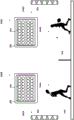
The light sources and lighting schemes may be employed in ways other than those described above to attenuate and/or enhance one or more players' performance and/or reduce the impact that skill differences have on the outcome of the game. Figure 4 depicts a top view of tennis court 342. Various spatial boundaries 450 are provided to define a plurality of bounded spaces 452A-J that form part of a tennis match. Most, if not all, spatial boundaries 450 of tennis court 342 may be created by illuminating, for example, one or more rows and/or columns of light sources implanted in the ground (e.g., such that they are level with the surface). For example, the entire two-dimensional array of light sources may be arranged below the glass ground, and a subset of these lights may be energized to form the spatial boundaries of any number of games other than tennis (such as basketball, hockey, indoor soccer, etc.). In some embodiments, in addition to or instead of creating a spatial boundary using light sources embedded in the ground, spatial boundary 450 may be created by operating light sources above the ground to project light onto a surface.
As shown in enlarged portion 454, in some embodiments, each spatial boundary 450 may be created using one or more light sources in the form of LEDs. The enlarged portion 454 illustrates three parallel LED strings. Only the LEDs in the middle string are energized to emit light. The LEDs of the strings at either side of the middle string are not energized to emit light. The middle LED string may be energized to create an enlarged spatial boundary 450 of the tennis court. However, in various embodiments, one of the other LED strings may be selectively energized using the techniques described herein, and/or the intermediate string may no longer be energized to change the location of the spatial boundary. Thus, for example, the space 452 bounded by the space boundary 450 may be slightly increased or decreased in size, making it easier or more difficult for opposing players to hit tennis balls into the boundary.
In some embodiments, the techniques described above may be combined. For example, when two tennis players with incomparable skills play on a tennis court, the spatial boundary at one or the other side (or both sides) may be changed to give a less skilled player a competitive advantage. At the same time, the lights facing more skilled players may be illuminated according to a lighting scheme that distracts, partially dazzles or otherwise impairs more skilled players.
Although the examples of fig. 3 and 4 depict how the disclosed techniques may be implemented on tennis court 342, the disclosed techniques may also be implemented on any other type of court. For example, the spatial boundaries of a basketball court may be altered to give one team or another or even individual players advantages or disadvantages. For example, a slightly shorter three-line may be marked for a less skilled team, or even for a particular player selecting a number of lights when that player is determined to be holding a ball. Similarly, demarcation, penalty and other lines may be moved and/or even hidden to provide advantages or disadvantages as desired. Additionally or alternatively, in some racing competitions, such as track and field competitions, horse races, race races, etc., the spatial boundary may mark a finish line for one or more participants. In some embodiments, the finish line for one player may be adjusted based on their handicap measures (or handicap measures based on other competitors) to make the game more competitive.
Additionally, and as mentioned above in describing the gaming computing device 122 over time, in various embodiments, the techniques described herein may be implemented in a single-player game. In some embodiments, the athlete may train with lighting systems and other components configured with selected aspects of the present disclosure. For example, a trained tennis player may practice her serve on a tennis court having a lighting created spatial boundary that may be altered as described above to reduce or increase difficulty. Similarly, a trained basketball player may practice free shots or tripartites on a basketball court having sidelines and/or tripartites created by lighting. In some embodiments, as the training competitor increases his or her skill level, the ambient or other lighting may be adjusted using the techniques described herein to gradually increase the difficulty of the training, e.g., so that the training competitor may improve his or her skill.
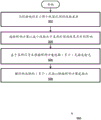
Fig. 5 depicts an example method 500 of practicing various aspects of the present disclosure. Although the operations of method 500 are depicted in a particular order, this is not meant to be limiting. Various operations may be reordered, added, or omitted in various embodiments. At block 502, a skill difference between at least two players of the game may be identified, for example, by skill balance engine 110 and/or player skill engine 114. As noted above, skill differences may be identified in various ways. In some embodiments, skill differences may be identified from records stored in player skill database 116. In some embodiments, skill differences may be identified based on signals received by the game progress monitor 118 from one or more sensors 120 that observe game progress between two or more players. As noted above, player skill can be expressed in a variety of ways. In some embodiments, player skill may be quantified numerically (e.g., in the range (e.g., 0-100) or as a handicap measure). In some embodiments, player skill may be represented as one of a list of enumerated skill levels (such as "novice," "intermediate," "advanced," "expert," etc.).
At block 504, a lighting scheme may be selected, for example, from the lighting scheme database 106, by the skill balancing engine 110 and/or the lighting system controller 102 to reduce the impact that the skill difference identified at block 502 has on the game outcome. Various example lighting schemes are described above and may include lighting schemes selected to distract, attenuate, ameliorate, temporarily dazzle, or otherwise affect one or more players of the game. Additionally or alternatively, one or more spatial boundaries on a surface, such as a floor of a field, or even a non-horizontal surface (e.g., a wall of a squash field, a square on a basketball board, a ring on a dart board, etc.) may be altered to impart advantages or disadvantages to one or more players. In a video game context, the lighting scheme may be selected to affect the ambient light that is normally used to illuminate the room to affect the performance of the video player.
At block 506, to implement the lighting scheme selected at block 504, one or more light sources (e.g., 104) may be selected, for example, from a plurality of available light sources. For example, a light source that would affect one or more specific players located in a particular area (e.g., one side of a tennis/volleyball/badminton court) may be selected to affect players in that particular area. Additionally or alternatively, light sources that are operated to mark one or more spatial boundaries for one or more players in a particular area may be selected, e.g., such that they may be operated to increase/decrease the area within the boundary, etc. In some embodiments, the illumination scheme may be inseparable from the particular light source on which it is to be implemented, in which case block 506 may be omitted.
At block 508, the light source(s) selected at block 506 may be operated according to the lighting scheme selected at block 504. Various examples of how lighting schemes may be implemented on light sources to reduce the impact that skill differences have on game results are described above, but are not meant to be limiting.
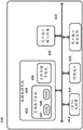
FIG. 6 is a block diagram of an example computer system 610. Computer system 610 typically includes at least one processor 614, which communicates with a number of peripheral devices via a bus subsystem 612. As used herein, the term "processor" will be understood to encompass a variety of devices, such as, for example, microprocessors, FPGAs, ASICs, other similar devices, and combinations thereof, capable of performing the various functions assigned to the various components described herein. These peripheral devices may include a data-holding subsystem 624 (including, for example, a memory subsystem 625 and a file storage subsystem 626), a user interface output device 620, a user interface input device 622, and a network interface subsystem 616. The input and output devices allow user interaction with computer system 610. Network interface subsystem 616 provides an interface to outside networks and is coupled to corresponding interface devices in other computer systems.
The user interface input devices 622 may include a keyboard, a pointing device such as a mouse, trackball, touchpad, or graphics tablet, a scanner, a touch screen incorporated into a display, an audio input device such as a voice recognition system, microphone, and/or other types of input devices. In general, use of the term "input device" is intended to include all possible types of devices and ways to input information into computer system 610 or onto a communication network.
User interface output devices 620 may include a display subsystem, a printer, a facsimile machine, or a non-visual display such as an audio output device. The display subsystem may include a Cathode Ray Tube (CRT), a flat panel device such as a Liquid Crystal Display (LCD), a projection device, or some other mechanism for creating a visible image. The display subsystem may also provide non-visual displays, such as via an audio output device. In general, use of the term "output device" is intended to include all possible types of devices and ways to output information from computer system 610 to a user, or to another machine or computer system.
These software modules are typically executed by processor 614 alone or in combination with other processors. Memory 625 used in the storage subsystem may include a plurality of memories including a main Random Access Memory (RAM) 630 for storing instructions and data during program execution, a Read Only Memory (ROM) 632 that stores fixed instructions, and other types of memory such as an instruction/data cache (which may additionally or alternatively be integrated with the at least one processor 614). File storage subsystem 626 may provide persistent storage for program and data files, and may include a hard disk drive, a floppy disk drive along with associated removable media, a CD-ROM drive, an optical drive, or a removable media cartridge. Modules implementing the functionality of certain embodiments may be stored by file storage subsystem 626 in data-holding system 624, or in a machine accessible by processor(s) 614. As used herein, the term "non-transitory computer readable medium" will be understood to encompass both volatile memory (e.g., DRAM and SRAM) and non-volatile memory (e.g., flash memory, magnetic storage, and optical storage), but to exclude transitory signals.
While several embodiments have been described and illustrated herein, those of ordinary skill in the art will readily envision a variety of other means and/or structures for performing the functions and/or obtaining the results and/or advantages described herein, and each of such variations and/or modifications is deemed to be within the scope of the embodiments described herein. More generally, those skilled in the art will readily appreciate that all parameters, dimensions, materials, and configurations described herein are meant to be exemplary and that the actual parameters, dimensions, materials, and/or configurations will depend upon the particular application or applications for which the teachings is/are used. Those skilled in the art will recognize, or be able to ascertain using no more than routine experimentation, many equivalents to the specific embodiments described herein. It is, therefore, to be understood that the foregoing embodiments are presented by way of example only and that, within the scope of the appended claims and equivalents thereto, the embodiments may be practiced otherwise than as specifically described and claimed. Embodiments of the present disclosure are directed to each individual feature, system, article, material, kit, and/or method described herein. In addition, any combination of two or more such features, systems, articles, materials, kits, and/or methods, if such features, systems, articles, materials, kits, and/or methods are not mutually inconsistent, is included within the scope of the present disclosure.
As defined and used herein, all definitions should be understood to control dictionary definitions, definitions in documents incorporated by reference, and/or general meanings of defined terms. The indefinite articles "a" or "an", as used herein in the specification and in the claims, should be understood to mean "at least one", unless explicitly indicated to the contrary. As used herein in the specification and claims, the phrase "and/or" should be understood to mean "either or both" of the elements so combined, i.e., the elements appear combined in some instances and not combined in other instances. The use of "and/or" a plurality of listed elements should be construed in the same manner, i.e., "one or more" of the elements so combined. Additional elements may optionally be present in addition to the elements specifically identified by the "and/or" phrase, whether related or unrelated to those specifically identified elements. Thus, as a non-limiting example, reference to "a and/or B" when used in conjunction with open language such as "comprising" may refer in one embodiment to a alone (optionally including other elements in addition to B); in another embodiment may refer to B only (optionally including other elements besides a); and in yet another embodiment may refer to both a and B (optionally including other elements), and so forth.
As used herein in the specification and claims, "or" should be understood to have the same meaning as "and/or" as defined above. For example, when an element is separated in a list, "or" and/or "should be interpreted as being inclusive, i.e., including at least one of the plurality of elements or list of elements, but also including more than one, and optionally including additional unlisted items. Merely explicitly indicated to the contrary, terms such as "only one of … …" or "exactly one of … …," or as used in the claims, "consisting of … …" will refer to the inclusion of a plurality of elements or exactly one element of a list of elements. In general, the term "or" as used herein should be construed to indicate an exclusive choice (i.e., "one or the other but not both") only when preceded by an exclusive term (such as "either," "one of … …," "only one of … …," or "exactly one of … …"). "consisting essentially of … …" when used in the claims shall have its ordinary meaning as used in the patent law.
As used herein in the specification and claims, the phrase "at least one," in reference to a list of one or more elements, should be understood to mean at least one element selected from any one or more of the elements of the list of elements, but not necessarily including at least one of each element specifically listed within the list of elements, and not excluding any combination of elements in the list of elements. This definition also allows that, in addition to the specifically identified elements in the list of elements to which the phrase "at least one" relates, other elements may optionally be present, whether related or unrelated to those specifically identified. Thus, as a non-limiting example, "at least one of a and B" (or, equivalently, "at least one of a or B," or, equivalently "at least one of a and/or B") can refer, in one embodiment, to at least one a, optionally including more than one a, with no B present (and optionally including other elements in addition to B); in another embodiment, may refer to at least one B, optionally including more than one B, with no a present (and optionally including other elements besides a); in yet another embodiment, may refer to at least one, optionally including more than one, a, and at least one, optionally including more than one, B (and optionally including other elements), and the like.
It will also be understood that, unless clearly indicated to the contrary, in any methods claimed herein that include more than one step or action, the order of the steps or actions of the method is not necessarily limited to the order in which the steps or actions of the method are recited. In the claims, as well as in the specification above, all transitional phrases such as "comprising," "including," "carrying," "having," "covering," "involving," "holding," "consisting of," and the like are to be understood to be open-ended, i.e., to mean including but not limited to. Only the transitional phrases "consisting of … …" and "consisting essentially of … …" should be respectively a closed or semi-closed transitional phrase, as explained in section 2111.03 of the patent office patent examination program manual. It should be understood that certain expressions and reference signs used in the claims are not limiting in scope in accordance with the provisions of the patent Cooperation treaty ("PCT") 6.2 (b).
Claims (13)
1. A computer-implemented method, comprising:
identifying (502), by one or more processors, a skill difference between at least two players of a game;
selecting (504), by one or more processors, a lighting scheme to reduce an impact the skill difference has on an outcome of a game; and
operating (508), by one or more processors, one or more light sources (104, 304) to emit ambient light according to the lighting scheme,
wherein the lighting scheme comprises attributes of the emitted light selected to impair or enhance the ability of one of the at least two players to play a game.
2. The method as recited in claim 1, further comprising selecting (506), by one or more processors, the one or more light sources from a plurality of light sources based on positions of the at least two players relative to the plurality of light sources.
3. The method of claim 2, wherein the one or more light sources emit light toward a first player having a first skill level different from a second skill level associated with a second player.
4. The method of claim 3, wherein the property of the emitted light comprises an intensity level.
5. The method of claim 3, wherein the attributes of the emitted light include glare or a dynamic lighting effect that distracts the first player.
6. The method of claim 2, wherein the one or more light sources are used to mark a spatial boundary (450) associated with the game.
7. The method of claim 6, wherein the one or more light sources are selected to change one or more dimensions of a space (452) marked by the space boundary.
8. The method of claim 6, wherein the one or more light sources are operated to change one or more dimensions of a space marked by the spatial boundary or to hide the spatial boundary.
9. The method of claim 1, further comprising continuously monitoring game progress between the at least two players and selecting a new lighting scheme based on the continuous monitoring.
10. The method of claim 1, wherein the one or more light sources are integrated with a moving object for playing a game.
11. An illumination system, comprising:
one or more light sources (104, 304); and
logic (114, 110, 102) operably coupled with the one or more light sources, wherein the logic is configured to:
identifying (502) a skill level of at least one player of the game;
selecting (504) an ambient lighting scheme to change the effect that the skill level of the at least one player has on the outcome of the game; and
operating (508) the one or more light sources to emit light according to the ambient lighting scheme,
wherein the ambient lighting scheme comprises attributes of the emitted light selected to impair the at least one player's ability to play a game.
12. The system of claim 11, further comprising a gaming computing device (122) operably coupled with the logic, wherein the game comprises a video game operated by the gaming computing device, and the logic identifies the skill level of the at least one player based on data obtained from the gaming computing device.
13. The system of claim 11, wherein the at least one player comprises a plurality of players distributed across a plurality of remote locations, and the one or more light sources comprise at least one light source at each of the plurality of remote locations.
Applications Claiming Priority (3)
| Application Number | Priority Date | Filing Date | Title |
|---|---|---|---|
| EP16181771.3 | 2016-07-28 | ||
| EP16181771 | 2016-07-28 | ||
| PCT/EP2017/067549 WO2018019590A1 (en) | 2016-07-28 | 2017-07-12 | Adaptive lighting based on skill level |
Publications (2)
| Publication Number | Publication Date |
|---|---|
| CN109691233A CN109691233A (en) | 2019-04-26 |
| CN109691233B true CN109691233B (en) | 2021-08-13 |
Family
ID=56683728
Family Applications (1)
| Application Number | Title | Priority Date | Filing Date |
|---|---|---|---|
| CN201780046423.9A Active CN109691233B (en) | 2016-07-28 | 2017-07-12 | Adaptive lighting based on skill level |
Country Status (5)
| Country | Link |
|---|---|
| US (1) | US10681789B2 (en) |
| EP (1) | EP3491895B1 (en) |
| JP (1) | JP7050749B2 (en) |
| CN (1) | CN109691233B (en) |
| WO (1) | WO2018019590A1 (en) |
Families Citing this family (4)
| Publication number | Priority date | Publication date | Assignee | Title |
|---|---|---|---|---|
| EP3536126B1 (en) | 2016-11-01 | 2022-03-30 | Signify Holding B.V. | A lighting-system and a lighting-system control method |
| CN111417442B (en) * | 2017-10-16 | 2023-08-08 | 乐高公司 | Interactive game device |
| US11644193B2 (en) * | 2019-11-26 | 2023-05-09 | M3 Innovation, LLC | Dual redundancy high reliability LED lighting platform |
| JP7479010B2 (en) * | 2020-07-31 | 2024-05-08 | パナソニックIpマネジメント株式会社 | Lighting control device, lighting control system, lighting system, lighting control method and program |
Citations (3)
| Publication number | Priority date | Publication date | Assignee | Title |
|---|---|---|---|---|
| CN2899374Y (en) * | 2005-02-11 | 2007-05-09 | 乐迪卡游戏机有限公司 | Electronic device of video game device |
| US9162134B2 (en) * | 2012-04-24 | 2015-10-20 | Ralph Schwartz | Lacrosse training and competitive game installation with variable trajectory control |
| CN105408677A (en) * | 2013-05-20 | 2016-03-16 | 玛斯柯有限公司 | Apparatus, system and method for glare reduction and uplighting for golf course, sports field and large area lighting |
Family Cites Families (13)
| Publication number | Priority date | Publication date | Assignee | Title |
|---|---|---|---|---|
| US7764026B2 (en) * | 1997-12-17 | 2010-07-27 | Philips Solid-State Lighting Solutions, Inc. | Systems and methods for digital entertainment |
| US6211626B1 (en) | 1997-08-26 | 2001-04-03 | Color Kinetics, Incorporated | Illumination components |
| US6016038A (en) | 1997-08-26 | 2000-01-18 | Color Kinetics, Inc. | Multicolored LED lighting method and apparatus |
| JP2007089608A (en) * | 2005-09-26 | 2007-04-12 | Aruze Corp | Table game device |
| US8952628B1 (en) * | 2009-11-05 | 2015-02-10 | Musco Corporation | Apparatus, system and method for providing intermittent uplighting |
| US20120276507A1 (en) | 2011-04-29 | 2012-11-01 | Dana Taylor | Athletic training device with lighted indicators |
| US8672782B2 (en) * | 2011-11-21 | 2014-03-18 | Nike, Inc. | Sporting devices and structures having dynamic visual indicia |
| US9084312B2 (en) * | 2011-12-07 | 2015-07-14 | Comcast Cable Communications, Llc | Dynamic ambient lighting |
| US10104329B2 (en) * | 2013-01-25 | 2018-10-16 | John Faratzis | Sports entertainment apparatus |
| EP3064040A1 (en) * | 2013-10-28 | 2016-09-07 | Philips Lighting Holding B.V. | Apparatus for controlling lighting parameters based on time of day and/or ambient light conditions and related methods |
| US9266002B2 (en) | 2014-04-04 | 2016-02-23 | Alex H. Dunser | Soccer training apparatus |
| US9706622B2 (en) * | 2014-05-16 | 2017-07-11 | Musco Corporation | Sports lighting to increase contrast of an aerial sports object relative to background |
| US9955555B2 (en) * | 2016-04-11 | 2018-04-24 | Noon Home, Inc. | Intelligent lighting control multi-switch apparatuses, systems, and methods |
-
2017
- 2017-07-12 WO PCT/EP2017/067549 patent/WO2018019590A1/en unknown
- 2017-07-12 JP JP2019504051A patent/JP7050749B2/en active Active
- 2017-07-12 US US16/321,062 patent/US10681789B2/en active Active
- 2017-07-12 CN CN201780046423.9A patent/CN109691233B/en active Active
- 2017-07-12 EP EP17736968.3A patent/EP3491895B1/en active Active
Patent Citations (3)
| Publication number | Priority date | Publication date | Assignee | Title |
|---|---|---|---|---|
| CN2899374Y (en) * | 2005-02-11 | 2007-05-09 | 乐迪卡游戏机有限公司 | Electronic device of video game device |
| US9162134B2 (en) * | 2012-04-24 | 2015-10-20 | Ralph Schwartz | Lacrosse training and competitive game installation with variable trajectory control |
| CN105408677A (en) * | 2013-05-20 | 2016-03-16 | 玛斯柯有限公司 | Apparatus, system and method for glare reduction and uplighting for golf course, sports field and large area lighting |
Also Published As
| Publication number | Publication date |
|---|---|
| EP3491895A1 (en) | 2019-06-05 |
| JP2019533487A (en) | 2019-11-21 |
| US10681789B2 (en) | 2020-06-09 |
| WO2018019590A1 (en) | 2018-02-01 |
| CN109691233A (en) | 2019-04-26 |
| JP7050749B2 (en) | 2022-04-08 |
| EP3491895B1 (en) | 2021-02-24 |
| US20190174607A1 (en) | 2019-06-06 |
Similar Documents
| Publication | Publication Date | Title |
|---|---|---|
| CN109691233B (en) | Adaptive lighting based on skill level | |
| CN105188862B (en) | Dart game device, darts method and computer-readable medium | |
| US9233289B2 (en) | Method for training players and sportsmen | |
| JP5909515B2 (en) | Basketball sensing device | |
| US20220314070A1 (en) | Immersive and reactive game play range, system and process | |
| WO2022024596A1 (en) | Illumination control device, illumination control system, illumination system, illumination control method and program | |
| JP6776560B2 (en) | Lighting environment evaluation method | |
| US20040124582A1 (en) | Tabletop game with lights | |
| US20220256665A1 (en) | Method and apparatus for managing large area lighting | |
| AU2020334148A1 (en) | Multiplayer, multisport indoor game system and method | |
| CN114177597A (en) | System, apparatus and method for ball throwing machine and smart goal | |
| WO2019213649A1 (en) | Method and apparatus for managing large area lighting | |
| US11406887B2 (en) | Multiplayer, multisport indoor game system and method | |
| WO2024018203A1 (en) | Training system and method of use thereof | |
| KR102664954B1 (en) | Virtual sports device having the function of sensing illumination | |
| JP2017083396A (en) | Lighting environment evaluation method | |
| WO2023154654A2 (en) | Interactive led system for enhancing billiard gameplay | |
| GB2387786A (en) | Football game | |
| US20040036210A1 (en) | Tabletop game with lighted playing field | |
| NL2015430B1 (en) | Ball game system for practicing by at least one player, an associated control unit, a related method and a computer program product. | |
| WO2017043973A1 (en) | Ballgame system to be played by at least one player, an accompanying control unit, a related work method and a computer program product | |
| JP2017062901A (en) | Illumination apparatus |
Legal Events
| Date | Code | Title | Description |
|---|---|---|---|
| PB01 | Publication | ||
| PB01 | Publication | ||
| SE01 | Entry into force of request for substantive examination | ||
| SE01 | Entry into force of request for substantive examination | ||
| CB02 | Change of applicant information |
Address after: Eindhoven Applicant after: Signify Holdings Ltd. Address before: Eindhoven, the Netherlands Applicant before: PHILIPS LIGHTING HOLDING B.V. |
|
| CB02 | Change of applicant information | ||
| GR01 | Patent grant | ||
| GR01 | Patent grant |