CN109640775B - Autonomous traveling floor cleaning machine - Google Patents
Autonomous traveling floor cleaning machine Download PDFInfo
- Publication number
- CN109640775B CN109640775B CN201780049940.1A CN201780049940A CN109640775B CN 109640775 B CN109640775 B CN 109640775B CN 201780049940 A CN201780049940 A CN 201780049940A CN 109640775 B CN109640775 B CN 109640775B
- Authority
- CN
- China
- Prior art keywords
- cleaning
- unit
- teaching
- cleaning liquid
- data acquisition
- Prior art date
- Legal status (The legal status is an assumption and is not a legal conclusion. Google has not performed a legal analysis and makes no representation as to the accuracy of the status listed.)
- Active
Links
- 238000004140 cleaning Methods 0.000 title claims abstract description 855
- 239000007788 liquid Substances 0.000 claims abstract description 186
- XLYOFNOQVPJJNP-UHFFFAOYSA-N water Substances O XLYOFNOQVPJJNP-UHFFFAOYSA-N 0.000 claims abstract description 89
- 238000007599 discharging Methods 0.000 claims abstract description 3
- 238000012937 correction Methods 0.000 claims description 52
- 238000010521 absorption reaction Methods 0.000 claims description 20
- 238000005406 washing Methods 0.000 description 56
- 238000003860 storage Methods 0.000 description 45
- 238000010586 diagram Methods 0.000 description 30
- 239000013598 vector Substances 0.000 description 25
- 238000000034 method Methods 0.000 description 23
- 238000003825 pressing Methods 0.000 description 20
- 238000004364 calculation method Methods 0.000 description 16
- 230000008569 process Effects 0.000 description 9
- 238000012545 processing Methods 0.000 description 7
- 238000006243 chemical reaction Methods 0.000 description 6
- 230000006870 function Effects 0.000 description 6
- 230000008859 change Effects 0.000 description 5
- 238000001514 detection method Methods 0.000 description 5
- 238000011084 recovery Methods 0.000 description 4
- 238000004891 communication Methods 0.000 description 3
- 238000009826 distribution Methods 0.000 description 2
- 239000000428 dust Substances 0.000 description 2
- 238000012986 modification Methods 0.000 description 2
- 230000004048 modification Effects 0.000 description 2
- 230000005856 abnormality Effects 0.000 description 1
- 230000009471 action Effects 0.000 description 1
- 230000000295 complement effect Effects 0.000 description 1
- 230000000694 effects Effects 0.000 description 1
- 238000011156 evaluation Methods 0.000 description 1
- 239000012530 fluid Substances 0.000 description 1
- -1 for example Substances 0.000 description 1
- 230000005484 gravity Effects 0.000 description 1
- 238000011086 high cleaning Methods 0.000 description 1
- 239000004973 liquid crystal related substance Substances 0.000 description 1
- 230000004807 localization Effects 0.000 description 1
- 238000013507 mapping Methods 0.000 description 1
- 238000005259 measurement Methods 0.000 description 1
- 238000012544 monitoring process Methods 0.000 description 1
- 230000009467 reduction Effects 0.000 description 1
- 230000004044 response Effects 0.000 description 1
Images


Classifications
-
- A—HUMAN NECESSITIES
- A47—FURNITURE; DOMESTIC ARTICLES OR APPLIANCES; COFFEE MILLS; SPICE MILLS; SUCTION CLEANERS IN GENERAL
- A47L—DOMESTIC WASHING OR CLEANING; SUCTION CLEANERS IN GENERAL
- A47L11/00—Machines for cleaning floors, carpets, furniture, walls, or wall coverings
- A47L11/40—Parts or details of machines not provided for in groups A47L11/02 - A47L11/38, or not restricted to one of these groups, e.g. handles, arrangements of switches, skirts, buffers, levers
- A47L11/4011—Regulation of the cleaning machine by electric means; Control systems and remote control systems therefor
-
- A—HUMAN NECESSITIES
- A47—FURNITURE; DOMESTIC ARTICLES OR APPLIANCES; COFFEE MILLS; SPICE MILLS; SUCTION CLEANERS IN GENERAL
- A47L—DOMESTIC WASHING OR CLEANING; SUCTION CLEANERS IN GENERAL
- A47L11/00—Machines for cleaning floors, carpets, furniture, walls, or wall coverings
- A47L11/02—Floor surfacing or polishing machines
- A47L11/10—Floor surfacing or polishing machines motor-driven
- A47L11/14—Floor surfacing or polishing machines motor-driven with rotating tools
- A47L11/16—Floor surfacing or polishing machines motor-driven with rotating tools the tools being disc brushes
- A47L11/162—Floor surfacing or polishing machines motor-driven with rotating tools the tools being disc brushes having only a single disc brush
- A47L11/1625—Floor surfacing or polishing machines motor-driven with rotating tools the tools being disc brushes having only a single disc brush with supply of cleaning agents
-
- A—HUMAN NECESSITIES
- A47—FURNITURE; DOMESTIC ARTICLES OR APPLIANCES; COFFEE MILLS; SPICE MILLS; SUCTION CLEANERS IN GENERAL
- A47L—DOMESTIC WASHING OR CLEANING; SUCTION CLEANERS IN GENERAL
- A47L11/00—Machines for cleaning floors, carpets, furniture, walls, or wall coverings
- A47L11/28—Floor-scrubbing machines, motor-driven
- A47L11/282—Floor-scrubbing machines, motor-driven having rotary tools
- A47L11/283—Floor-scrubbing machines, motor-driven having rotary tools the tools being disc brushes
-
- A—HUMAN NECESSITIES
- A47—FURNITURE; DOMESTIC ARTICLES OR APPLIANCES; COFFEE MILLS; SPICE MILLS; SUCTION CLEANERS IN GENERAL
- A47L—DOMESTIC WASHING OR CLEANING; SUCTION CLEANERS IN GENERAL
- A47L11/00—Machines for cleaning floors, carpets, furniture, walls, or wall coverings
- A47L11/29—Floor-scrubbing machines characterised by means for taking-up dirty liquid
- A47L11/292—Floor-scrubbing machines characterised by means for taking-up dirty liquid having rotary tools
- A47L11/293—Floor-scrubbing machines characterised by means for taking-up dirty liquid having rotary tools the tools being disc brushes
-
- A—HUMAN NECESSITIES
- A47—FURNITURE; DOMESTIC ARTICLES OR APPLIANCES; COFFEE MILLS; SPICE MILLS; SUCTION CLEANERS IN GENERAL
- A47L—DOMESTIC WASHING OR CLEANING; SUCTION CLEANERS IN GENERAL
- A47L11/00—Machines for cleaning floors, carpets, furniture, walls, or wall coverings
- A47L11/29—Floor-scrubbing machines characterised by means for taking-up dirty liquid
- A47L11/30—Floor-scrubbing machines characterised by means for taking-up dirty liquid by suction
- A47L11/302—Floor-scrubbing machines characterised by means for taking-up dirty liquid by suction having rotary tools
- A47L11/305—Floor-scrubbing machines characterised by means for taking-up dirty liquid by suction having rotary tools the tools being disc brushes
-
- A—HUMAN NECESSITIES
- A47—FURNITURE; DOMESTIC ARTICLES OR APPLIANCES; COFFEE MILLS; SPICE MILLS; SUCTION CLEANERS IN GENERAL
- A47L—DOMESTIC WASHING OR CLEANING; SUCTION CLEANERS IN GENERAL
- A47L11/00—Machines for cleaning floors, carpets, furniture, walls, or wall coverings
- A47L11/40—Parts or details of machines not provided for in groups A47L11/02 - A47L11/38, or not restricted to one of these groups, e.g. handles, arrangements of switches, skirts, buffers, levers
- A47L11/4036—Parts or details of the surface treating tools
- A47L11/4044—Vacuuming or pick-up tools; Squeegees
-
- A—HUMAN NECESSITIES
- A47—FURNITURE; DOMESTIC ARTICLES OR APPLIANCES; COFFEE MILLS; SPICE MILLS; SUCTION CLEANERS IN GENERAL
- A47L—DOMESTIC WASHING OR CLEANING; SUCTION CLEANERS IN GENERAL
- A47L11/00—Machines for cleaning floors, carpets, furniture, walls, or wall coverings
- A47L11/40—Parts or details of machines not provided for in groups A47L11/02 - A47L11/38, or not restricted to one of these groups, e.g. handles, arrangements of switches, skirts, buffers, levers
- A47L11/408—Means for supplying cleaning or surface treating agents
- A47L11/4088—Supply pumps; Spraying devices; Supply conduits
-
- A—HUMAN NECESSITIES
- A47—FURNITURE; DOMESTIC ARTICLES OR APPLIANCES; COFFEE MILLS; SPICE MILLS; SUCTION CLEANERS IN GENERAL
- A47L—DOMESTIC WASHING OR CLEANING; SUCTION CLEANERS IN GENERAL
- A47L9/00—Details or accessories of suction cleaners, e.g. mechanical means for controlling the suction or for effecting pulsating action; Storing devices specially adapted to suction cleaners or parts thereof; Carrying-vehicles specially adapted for suction cleaners
- A47L9/28—Installation of the electric equipment, e.g. adaptation or attachment to the suction cleaner; Controlling suction cleaners by electric means
-
- G—PHYSICS
- G05—CONTROLLING; REGULATING
- G05D—SYSTEMS FOR CONTROLLING OR REGULATING NON-ELECTRIC VARIABLES
- G05D1/00—Control of position, course, altitude or attitude of land, water, air or space vehicles, e.g. using automatic pilots
- G05D1/02—Control of position or course in two dimensions
-
- G—PHYSICS
- G05—CONTROLLING; REGULATING
- G05D—SYSTEMS FOR CONTROLLING OR REGULATING NON-ELECTRIC VARIABLES
- G05D1/00—Control of position, course, altitude or attitude of land, water, air or space vehicles, e.g. using automatic pilots
- G05D1/02—Control of position or course in two dimensions
- G05D1/021—Control of position or course in two dimensions specially adapted to land vehicles
- G05D1/0212—Control of position or course in two dimensions specially adapted to land vehicles with means for defining a desired trajectory
- G05D1/0219—Control of position or course in two dimensions specially adapted to land vehicles with means for defining a desired trajectory ensuring the processing of the whole working surface
-
- G—PHYSICS
- G05—CONTROLLING; REGULATING
- G05D—SYSTEMS FOR CONTROLLING OR REGULATING NON-ELECTRIC VARIABLES
- G05D1/00—Control of position, course, altitude or attitude of land, water, air or space vehicles, e.g. using automatic pilots
- G05D1/02—Control of position or course in two dimensions
- G05D1/021—Control of position or course in two dimensions specially adapted to land vehicles
- G05D1/0212—Control of position or course in two dimensions specially adapted to land vehicles with means for defining a desired trajectory
- G05D1/0221—Control of position or course in two dimensions specially adapted to land vehicles with means for defining a desired trajectory involving a learning process
-
- A—HUMAN NECESSITIES
- A47—FURNITURE; DOMESTIC ARTICLES OR APPLIANCES; COFFEE MILLS; SPICE MILLS; SUCTION CLEANERS IN GENERAL
- A47L—DOMESTIC WASHING OR CLEANING; SUCTION CLEANERS IN GENERAL
- A47L2201/00—Robotic cleaning machines, i.e. with automatic control of the travelling movement or the cleaning operation
- A47L2201/04—Automatic control of the travelling movement; Automatic obstacle detection
-
- A—HUMAN NECESSITIES
- A47—FURNITURE; DOMESTIC ARTICLES OR APPLIANCES; COFFEE MILLS; SPICE MILLS; SUCTION CLEANERS IN GENERAL
- A47L—DOMESTIC WASHING OR CLEANING; SUCTION CLEANERS IN GENERAL
- A47L2201/00—Robotic cleaning machines, i.e. with automatic control of the travelling movement or the cleaning operation
- A47L2201/06—Control of the cleaning action for autonomous devices; Automatic detection of the surface condition before, during or after cleaning
Landscapes
- Engineering & Computer Science (AREA)
- Aviation & Aerospace Engineering (AREA)
- Radar, Positioning & Navigation (AREA)
- Remote Sensing (AREA)
- Physics & Mathematics (AREA)
- General Physics & Mathematics (AREA)
- Automation & Control Theory (AREA)
- Mechanical Engineering (AREA)
- Electric Vacuum Cleaner (AREA)
- Control Of Position, Course, Altitude, Or Attitude Of Moving Bodies (AREA)
Abstract
In an autonomous floor cleaning machine, an appropriate cleaning operation is autonomously performed without leaving a cleaning liquid on a floor surface. The autonomous floor cleaning machine (100) autonomously travels in accordance with a cleaning protocol (500), and cleans a floor surface (F) using a suction wiper (33) and a cleaning liquid. In an autonomous floor cleaning machine (100), a discharge position (P) of a cleaning liquid at a teaching data acquisition timew) Not included in the case of the water sucking rake track calculated based on the position and width of the water sucking rake (33) in the teaching data acquisition time, so as to enable the discharging position (P) of the cleaning liquidw) The cleaning protocol (500) is modified in a manner that is included in the swab trajectory.
Description
Technical Field
The present invention relates to an autonomous floor cleaning machine which autonomously travels and performs cleaning by reproducing a cleaning condition and a travel path to be taught.
Background
Conventionally, there is known an autonomous floor cleaning machine (hereinafter referred to as a cleaning machine) which autonomously travels a travel path taught by a user operation by reproducing the travel path and a cleaning condition taught by the user operation and autonomously performs cleaning in accordance with the cleaning condition taught (for example, see patent document 1). This cleaning machine performs a cleaning operation while traveling on a floor surface, and in the cleaning operation, a cleaning liquid is supplied to the floor surface and the floor surface is cleaned with a cleaning brush or the like, and then the cleaning liquid used for cleaning is collected by a water suction rake (squeegee).
Documents of the prior art
Patent document
Patent document 1: japanese patent laid-open publication No. 2015-58131
Disclosure of Invention
In the cleaning machine disclosed in patent document 1, for example, a user may mistake the operation of the cleaning machine, and an unskilled user may perform an operation without considering the structure of the cleaning machine (such as the positional relationship between the suction device and the supply port of the cleaning liquid), and may create a cleaning schedule (cleaning schedule) in which the cleaning liquid used for cleaning cannot be collected by the suction device at the time of reproduction. As a result, when the cleaning machine autonomously performs the cleaning operation in accordance with the cleaning procedure, the cleaning liquid after use may remain on the floor surface and proper cleaning may not be achieved.
The present invention has an object to autonomously perform an appropriate cleaning operation in which a cleaning liquid does not remain on a floor surface in a cleaning machine that autonomously performs a cleaning operation using a cleaning liquid taught by a user.
Hereinafter, a plurality of embodiments will be described as means for solving the problem. These modes can be arbitrarily combined as required.
An autonomous floor cleaning machine according to an aspect of the present invention autonomously travels and performs cleaning by reproducing a cleaning condition and a travel path that are taught. The autonomous floor cleaning machine includes a cleaning unit, a traveling unit, a position estimating unit, a cleaning condition teaching unit, a travel path teaching unit, a teaching data acquiring unit, a cleaning rule creating unit, a cleaning rule correcting unit, and a cleaning reproducing unit.
The cleaning unit has a cleaning liquid discharge port for discharging the cleaning liquid to the floor surface and a wiper (squeegee) for collecting the cleaning liquid present on the floor surface, and cleans the floor surface in accordance with the cleaning conditions. The traveling unit travels in accordance with an operation by an operator or a travel control instruction. The position estimating unit estimates position information including information on a position and a posture of the traveling unit on the travel path at predetermined coordinates. The cleaning condition teaching unit receives an input of a cleaning condition from an operator and outputs the input to the cleaning unit. The travel path teaching unit receives a movement operation of the operator on the travel unit.
The teaching data acquisition unit acquires teaching position information and teaching cleaning conditions at a teaching data acquisition time when a manual operation teaching mode is executed. The manual operation teaching mode is a mode for teaching a cleaning condition and a travel path formed based on an operation by an operator. The teaching position information is position information estimated by the position estimating unit. The taught cleaning condition is a cleaning condition taught in the cleaning condition teaching section.
The cleaning procedure creation section creates and stores a cleaning procedure (cleaning schedule). The cleaning procedure is data in which the teaching position information and the teaching cleaning condition are associated with the teaching data acquisition time.
The cleaning rule correcting unit corrects the cleaning rule so that the discharge position of the cleaning liquid is included in the water-sucking rake track when the discharge position of the cleaning liquid at the teaching data acquisition time is not included in the water-sucking rake track at the teaching data acquisition time. The water absorption rake track is a track of the water absorption rake calculated based on the position and width of the water absorption rake at the time of acquisition of the teaching data. The discharge position of the cleaning liquid is calculated based on the position of the cleaning liquid discharge port at the time of teaching data acquisition.
The cleaning reproduction unit calculates a reproduced cleaning condition and a reproduced travel control command at a predetermined elapsed time from the start of execution of the autonomous cleaning mode, based on the teaching data acquisition time, the teaching cleaning condition, and the teaching position information stored in the cleaning protocol created by the cleaning protocol creation unit or the cleaning protocol corrected by the cleaning protocol correction unit. The cleaning reproduction unit outputs the reproduced cleaning condition and the reproduced travel control command to the cleaning unit and the travel unit, respectively. The autonomous cleaning mode is a mode in which travel and cleaning are performed autonomously.
In the autonomous floor cleaning machine, if the discharge position of the cleaning liquid not included in the water suction rake track exists in the cleaning rule created by the cleaning rule creation unit, the cleaning rule correction unit corrects the cleaning rule so that the discharge position of the cleaning liquid is included in the water suction rake track, thereby creating a new cleaning rule.
When a new corrected cleaning procedure is created, the cleaning reproduction unit outputs a reproduction cleaning condition calculated based on the new cleaning procedure to the cleaning unit, and outputs a reproduction travel control command calculated based on the new cleaning procedure to the travel unit.
Thus, even when a cleaning rule for performing a cleaning operation in which used cleaning liquid remains on the floor surface is created during execution of the manual operation teaching mode, the autonomous floor cleaning machine corrects the cleaning rule, and can autonomously perform an appropriate cleaning operation in which cleaning liquid does not remain on the floor surface.
The cleaning rule correcting unit may calculate the water scooping trajectory based on the position and width of the water scooping device at two teaching data acquisition times and the positions and widths of a plurality of virtual water scooping devices assumed between the two teaching data acquisition times.
This makes it possible to calculate a water scooping trajectory that represents a movement trajectory closer to the actual water scooping trajectory. As a result, it is possible to accurately execute whether or not the discharge position of the cleaning liquid is included in the water scooping trajectory.
The cleaning condition may include a discharge amount of the cleaning liquid discharged from the cleaning liquid discharge port. In this case, the cleaning rule correction unit corrects the cleaning rule by setting the discharge amount of the cleaning liquid at the discharge position of the cleaning liquid not included in the water sucking trajectory to 0.
By correcting the cleaning protocol so that the cleaning liquid is not discharged at the discharge position of the cleaning liquid not included in the water scooping trajectory, it is possible to create a new cleaning protocol in which the cleaning liquid is supplied only at the discharge position of the cleaning liquid included in the water scooping trajectory.
The cleaning unit may further include a suction port for sucking the cleaning liquid on the floor surface. In this case, the cleaning condition includes a suction force of the cleaning liquid by the suction port. The cleaning rule correcting unit corrects the cleaning rule by increasing the suction force of the cleaning liquid at the discharge position of the cleaning liquid not included in the water sucking trajectory.
By increasing the suction force of the cleaning liquid at the discharge position of the cleaning liquid not included in the suction rake locus, the collection range of the cleaning liquid by the suction rake is expanded, and the discharge position of the cleaning liquid can be included in the suction rake locus in the new cleaning rule after the correction.
The cleaning rule correcting unit may determine whether or not the discharge position of the cleaning liquid is present on the water scooping trajectory within a range from a current teaching data acquisition time to a teaching data acquisition time after a predetermined time has elapsed. Thus, when the autonomous cleaning mode is executed, it is possible to suppress execution of improper cleaning in which the cleaning liquid discharged at a certain elapsed time remains on the floor surface for a long time.
Effects of the invention
The autonomous floor cleaning machine can autonomously perform an appropriate cleaning operation without leaving a cleaning liquid on the floor surface even if an inappropriate cleaning procedure is created in the manual operation teaching mode.
Drawings
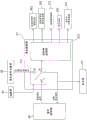
Fig. 1 is a diagram showing an overall configuration of an autonomous floor cleaning machine.
Fig. 2 is a diagram showing an example of the configuration of the travel path teaching section.
Fig. 3 is a diagram showing the configuration of the setting unit.
Fig. 4 is a diagram showing the overall configuration of the control unit.
Fig. 5 is a diagram showing an example of a virtual model of the cleaning machine.
Fig. 6 is a diagram showing a detailed configuration of the cleaning control unit.
Fig. 7 is a diagram showing a detailed configuration of the travel control unit.
Fig. 8 is a diagram showing a detailed configuration of the central control unit.
Fig. 9A is a flowchart showing a basic operation of the autonomous floor cleaning machine.
Fig. 9B is a flowchart showing an operation in the manual operation teaching mode.
Fig. 10 is a diagram showing an example of a cleaning procedure.
Fig. 11 is an example of a coordinate system defining the position information.
Fig. 12 is a flowchart showing a cleaning procedure correction process.
Fig. 13 is a diagram showing an example of a virtual model of the autonomous floor cleaning machine before and after movement.
Fig. 14A is a diagram schematically showing an example of processing performed when it is determined that the joint is rotated by a predetermined angle or more (fig. 1).
Fig. 14B is a diagram schematically showing an example of processing performed when it is determined that the joint is rotated by a predetermined angle or more (fig. 2).
Fig. 15 is a diagram showing an example of the water scooping trajectory.
Fig. 16 is a diagram schematically showing a method of determining whether or not the discharge position of the cleaning liquid is included in the water scooping trajectory.
Fig. 17A is a diagram showing an example of the relationship between the water scooping trajectory and the discharge position in the case where the movement path is not subdivided.
Fig. 17B is a diagram showing an example of a case where it is determined that the calculated water-sucking raking trajectory in which the movement path is subdivided includes the following discharge position determined not to be included in the calculated water-sucking raking trajectory in which the movement path is not subdivided.
Fig. 18 is a flowchart showing the operation of the autonomous floor cleaning machine in the autonomous cleaning mode.
Detailed Description
1. Embodiment 1
(1) Integral structure of autonomous traveling floor cleaning machine
First, the overall configuration of the autonomous floor cleaning machine according to the present embodiment will be described with reference to fig. 1. Fig. 1 is a diagram showing an overall configuration of an autonomous floor cleaning machine 100. The autonomous traveling floor cleaning machine 100 shown in fig. 1 (hereinafter simply referred to as the cleaning machine 100) autonomously performs a cleaning operation by faithfully reproducing a cleaning condition and a traveling path to be taught. The "taught cleaning condition" is a condition (cleaning condition) for cleaning performed by manual operation of an operator when the cleaning machine 100 is in a state in which manual operation is possible. The "taught travel path" refers to a path along which the washing machine 100 travels in response to a manual operation (moving operation) by an operator.
The cleaning machine 100 includes a traveling unit 1. The traveling unit 1 is a device for traveling the washing machine 100. The traveling unit 1 includes a traveling motor 11 and a main wheel 13 attached to an output rotation shaft of the traveling motor 11 and rotating with the rotation of the traveling motor 11 at each of left and right ends of a bottom portion of the main body B.
As another embodiment, the traveling unit 1 may have auxiliary wheels 15 rotatably attached to the left and right ends of the bottom of the main body B and behind the main wheel 13, for example. This makes the washer 100 more stable. As still another embodiment, the auxiliary wheel 15 may be attached to the front of the main wheel 13 in consideration of the position of the center of gravity of the washing machine 100.
The cleaning machine 100 includes a cleaning unit 3. The cleaning unit 3 is a device that is provided at the bottom of the main body B and cleans the floor surface F in accordance with a predetermined cleaning condition. Details about the cleaning portion 3 will be described later.
The washer 100 has a control unit 5. The control unit 5 is a computer system having a CPU, a storage device (RAM, ROM, hard disk drive, SSD, etc.), various interfaces, and the like. The control unit 5 performs various controls related to the washing machine 100. The structure of the control section 5 will be described in detail later.
The cleaning machine 100 includes a travel path teaching section 7. The travel path teaching section 7 is a device that receives a movement operation of the travel section 1 by an operator. The travel path teaching section 7 is attached to the upper rear side of the main body B via an attachment member 8. Thus, the operator can operate the travel path teaching section 7 to move the traveling section 1. Details of the travel path teaching section 7 will be described later.
As another embodiment, the travel path teaching section 7 may not be attached to the main body B. In this case, the travel path teaching section 7 may be a controller such as a joystick (joystick). Thereby, the operator can remotely operate the washing machine 100.
The washing machine 100 includes a setting unit 9. The setting unit 9 is an operation panel for performing various settings related to the washing machine 100, and is attached to the upper rear surface of the main body B. The setting unit 9 is provided near the travel path teaching unit 7. Thus, the operator can operate the setting unit 9 while operating the travel path teaching unit 7 to operate the travel unit 1.
As another embodiment, the setting unit 9 may not be attached to the main body B. In this case, the setting unit 9 is a console such as a mobile terminal capable of wireless communication. Thereby, the operator can set the washer 100 remotely.
As still another embodiment, the travel path teaching section 7 and the setting section 9 may be integrated. This makes it easy to simultaneously operate the traveling unit 1 and the setting unit.
(2) Structure of cleaning part
Next, the structure of the cleaning unit 3 will be described with reference to fig. 1. The cleaning unit 3 cleans the floor surface F in accordance with the cleaning conditions.
The cleaning unit 3 has a cleaning liquid discharge port 31. The cleaning liquid discharge port 31 is a hollow member that discharges the cleaning liquid from one end thereof, for example. For example, one end of a hollow member constituting the cleaning liquid discharge port 31 is disposed at a position corresponding to the cavity O1 provided in the fixing member 351, and the fixing member 351 fixes the cleaning member 35. On the other hand, the other end of the member is connected to an outlet side of a cleaning liquid supply pump 311 that supplies a cleaning liquid.
An inlet side of the cleaning liquid supply pump 311 is connected to an outlet of a cleaning liquid supply tank 313, the cleaning liquid supply tank 313 is mounted inside the main body B, and the cleaning liquid is stored inside the cleaning liquid supply tank 313. According to this configuration, the cleaning liquid stored in the cleaning liquid supply tank 313 is supplied to the cleaning liquid discharge port 31 by adjusting the supply amount thereof by the cleaning liquid supply pump 311, and is discharged from one end of the cleaning liquid discharge port 31 to the floor surface F via the cavity O1. As the cleaning liquid, for example, water can be used.
The cleaning part 3 has a wiper 33. The wiper 33 is fixed to the wiper fixing member 331, is provided behind the bottom surface of the main body B, and collects the cleaning liquid remaining on the floor surface F (cleaning liquid used for cleaning the floor surface F). The wiper 33 extends in the width direction of the body B by a predetermined length, and moves with the movement of the body B, thereby forming a region (referred to as a wiper locus) defined by the movement locus of the body B and the length of the wiper 33 in the width direction. The squeegees 33 collect the cleaning fluid within the squeegees trajectory.
The wiper fixing member 331 is connected to the main body B via a joint J, and is rotatable around the joint J within a predetermined angular range (denoted by Θ) (fig. 5). The rotation of the swab fixing member 331 allows the angle of the swab 33 with respect to the front-rear direction of the main body B (the moving direction of the cleaning machine 100) to be changed.
In another embodiment, the suction port O2 may be provided in the suction attachment member 331. The suction port O2 is connected to a recovery member 335 (for example, a container having a cavity) which is sucked by a suction motor 333 and has a negative pressure inside. Thus, when the recovery member 335 is brought into a negative pressure by the suction of the suction motor 333, the suction port O2 generates the suction force P. As a result, the suction port O2 can suck the cleaning liquid, dust, and the like collected by the suction wiper 33 by the suction force P and convey the cleaning liquid, dust, and the like to the collection member 335. For example, the suction force P generated by the suction port O2 can be adjusted by adjusting the output of the suction motor 333.
In still another embodiment, the suction attachment member 331 may be connected to the suction raising/lowering actuator 337 via a joint J, and may be raised and lowered with respect to the floor surface F. Thus, the wiper 33 can be set to be in contact with or separated from the floor surface F at will. As a result, the water scooping device 33 can suppress the liquid (cleaning liquid) on the floor surface F from moving rearward of the cleaning machine 100 as necessary.
In still another embodiment, the water scooping tool 33 may be separated from the floor surface F when the cleaning machine 100 travels backward. This can prevent the liquid or the like on the floor surface F from moving further rearward of the cleaning machine 100 during the backward movement. As a result, the cleaning machine 100 can efficiently clean the floor surface F.
The cleaning unit 3 has a cleaning member 35. The cleaning member 35 is a member for cleaning the floor surface F fixed to the fixing member 351, wherein the fixing member 351 is provided on the front side of the bottom surface of the main body B. The fixing member 351 is connected to an output rotation shaft of the cleaning member rotating motor 353. Therefore, the cleaning member 35 rotates on the floor surface F on which the cleaning liquid is placed in accordance with the rotation of the cleaning member rotating motor 353, thereby cleaning the floor surface F.
In another embodiment, the cleaning member 35 may be connected to the cleaning member pressing actuator 357 via the pressing member 355. Thus, the cleaning member 35 can clean the floor surface F while being pressed against the floor surface F and rotated. By adjusting the rotation speed of the cleaning member rotating motor 353 and the pressing force of the cleaning member pressing actuator 357, the cleaning force of the cleaning member 35 against the floor surface F can be adjusted. As the cleaning member 35, for example, a brush for floor surface cleaning or the like can be used.
By configuring the cleaning unit 3 as described above, the cleaning machine 100 can perform various cleaning operations such as cleaning the floor surface F and collecting a liquid (cleaning liquid) on the floor surface F.
(3) Structure of travel path teaching section
Next, an example of the configuration of the travel path teaching section 7 according to the present embodiment will be described with reference to fig. 2. Fig. 2 is a diagram showing an example of the configuration of the travel path teaching section.
The travel path teaching section 7 includes handles 71a and 71 b. The handles 71a and 71b are attached to the left and right side surfaces of the housing 73, respectively. The handles 71a, 71b are used by a user when operating the washing machine 100.
For example, the operator who grips the handles 71a and 71b applies either a force for pulling the washer 100 toward the operator or a force for pushing the washer 100 out, via the handles 71a and 71 b. By adjusting the force applied to each of the handles 71a, 71b, the operator can adjust the direction of travel of the washing machine 100. For example, when a force for pulling the washer 100 is applied to the handle 71a on the left side when viewed from the front direction of the washer 100, the washer 100 turns left.
The handles 71a and 71b are rotatably attached to the housing 73. The handles 71a and 71b are connected to the control unit 5 via a travel control command calculation unit 75. The travel control command calculation unit 75 converts the rotation of the handles 71a and 71b into an electric signal and outputs the electric signal to the control unit 5. Thus, the operator can operate the washing machine 100 (traveling unit 1) by rotating the handles 71a and 71 b.
For example, the operator may switch between forward and backward movements of the washing machine 100 by adjusting the rotational direction of the handles 71a and 71 b. The travel speed of the washer 100 may be adjusted by adjusting the amount of rotation of the handles 71a and 71 b. Further, the forward direction of the washer 100 may be changed by making the amount of rotation of the handle 71a different from the amount of rotation of the handle 71 b.
As another embodiment, the handle 71a may be an input interface for instructing a traveling speed in the forward direction, and the handle 71b may be an input interface for instructing a steering angle.
(4) Structure of setting part
Next, the configuration of the setting unit 9 will be described with reference to fig. 3. Fig. 3 is a diagram showing the configuration of the setting unit.
The setting unit 9 has a switching unit 91. The switching unit 91 selects the operation mode of the washing machine 100 and outputs the selected operation mode to the control unit. As the operation mode of the washing machine 100, there are an autonomous cleaning mode and a manual operation mode. The autonomous cleaning mode is an operation mode in which the cleaning machine 100 autonomously travels and cleans the floor surface F. On the other hand, the manual operation mode is an operation mode in which the washing machine 100 is in a state in which it can be manually operated by the operator.
The switching unit 91 can be constituted by a switch as shown in fig. 3, for example. In this case, the selection of the autonomous cleaning mode can be realized by switching the switching unit 91 formed of a switch to "automatic" as shown in fig. 3, for example. On the other hand, the manual operation mode can be selected by switching the switching unit 91 to "manual" as shown in fig. 3, for example.
The setting unit 9 has a manually operated storage switch 92. The manual operation storage switch 92 is a switch for starting or ending storage of a manual operation of the washing machine 100 by an operator. Specifically, when the operation mode is set to the manual operation mode by the switching unit 91 and then the manual operation storage switch 92 is switched, the manual operation teaching mode in which the cleaning condition and the travel path are taught by the manual operation of the operator to the cleaning machine 100 is started as the sub operation mode of the manual operation mode. On the other hand, when the manual operation storage switch 92 is switched during execution of the manual operation teaching mode, the manual operation teaching mode is stopped.
Since the manual operation storage switch 92 can be used to start and stop the manual operation teaching mode, the manual operation teaching mode can be started or stopped at an arbitrary timing. As a result, the cleaning procedure 500 desired by the operator can be created.
The manual operation storage switch 92 may be, for example, a push button switch as shown in fig. 3. In this case, the manual operation of the memory switch 92 can be switched by pressing the button switch.
In another embodiment, when the manual operation storage switch 92 is switched when the manual operation teaching mode is executed, the operation mode may be switched from the manual operation teaching mode to the manual operation mode. Thus, even if the operator switches the manual operation teaching mode to the manual operation mode, the operator can continue to manually operate the washing machine 100.
The setting unit 9 includes a cleaning condition teaching unit 93. The cleaning condition teaching unit 93 receives an input of a cleaning condition from an operator, and outputs the input to the cleaning control command calculation unit 94. The cleaning control command calculation unit 94 is a signal conversion circuit or a computer system that converts the cleaning conditions received by the cleaning condition teaching unit 93 into signals that can be interpreted by the control unit 5.
As shown in fig. 3, the cleaning condition teaching section 93 includes a cleaning condition adjusting section 931. The cleaning condition adjustment portion 931 has a supply amount adjustment portion 931a that sets a supply amount S (an example of a discharge amount) of the cleaning liquid discharged from the cleaning liquid discharge port 31 as a teaching cleaning condition. The supply amount adjustment unit 931a may be configured by, for example, a push switch, and the supply amount S may be set according to the number of times the push switch is pressed.
In another embodiment, the cleaning condition adjustment portion 931 may include a suction force adjustment portion 931b that sets the suction force P of the suction port O2 to the teaching cleaning condition. The suction force adjustment portion 931b is, for example, a push button switch, and can adjust the suction force P in accordance with the number of times the button is pressed. This makes it possible to adjust the suction range of the cleaning liquid present on the floor surface F.
In still another embodiment, the cleaning condition adjustment portion 931 may include a cleaning force adjustment portion 931c that sets the cleaning force W of the cleaning member 35 with respect to the floor surface F to the teaching cleaning condition. The cleaning force adjusting portion 931c is, for example, a push switch, and can adjust the cleaning force W of the cleaning member 35 against the floor surface F according to the number of times the push switch is pushed.
In still another embodiment, the cleaning condition adjustment portion 931 may include all of the supply amount adjustment portion 931a, the suction force adjustment portion 931b, and the cleaning force adjustment portion 931 c. Thus, teaching cleaning conditions for individually adjusting the supply amount S of the cleaning liquid, the suction force P of the suction port O2, and/or the cleaning force W of the floor surface F can be set.
The cleaning condition teaching unit 93 includes an operation switching unit 933. The operation switching part 933 has a supply switching part 933a that instructs to start or stop the supply of the cleaning liquid from the cleaning liquid discharge port 31. The supply switching unit 933a can be configured by, for example, a button switch, and can switch between start and stop of supply of the cleaning liquid by pressing a button.
In another embodiment, the operation switch 933 may have a suction switch 933b that instructs start or stop of suction through the suction port O2. The suction switching unit 933b is, for example, a button switch, and can switch between suction start and suction stop by pressing a button.
In still another embodiment, the operation switching unit 933 may have a cleaning switching unit 933c for instructing to start or stop cleaning of the floor surface F by the cleaning member 35. The cleaning switching unit 933c is, for example, a push switch, and can switch between start and stop of cleaning of the floor surface F by pressing a button.
In still another embodiment, the operation switch 933 may have a supply switch 933a, a suction switch 933b, and a cleaning switch 933 c. This allows switching between the supply of the cleaning liquid, the suction through the suction port O2, and the start and stop of cleaning the floor surface F.
As a result, the washer 100 can execute, for example: the cleaning operation of sucking the cleaning liquid by the suction switching portion 933b is started after the supply of the cleaning liquid is stopped by the supply switching portion 933a, and/or the cleaning operation of cleaning the floor surface F is started by the cleaning switching portion 933c after a lapse of a time period required for the cleaning liquid to adhere to the floor surface F after the supply of the cleaning liquid is stopped by the supply switching portion 933 a.
The setting unit 9 includes a cleaning control command calculation unit 94. The cleaning control command calculation unit 94 is, for example, a signal conversion circuit or a computer system that converts the teaching cleaning conditions set by the cleaning condition adjustment unit 931 and the switching command of the operation switching unit 933 into signals interpretable by the control unit 5 and outputs the signals to the control unit 5.
The setting unit 9 has a setting operation unit 95. The setting operation unit 95 is configured by, for example, a push switch, receives input of various settings related to the washing machine 100, and outputs the input to the control unit 5 via the setting conversion unit 96. The setting operation unit 95 sets the validity or invalidity of the function of correcting the created cleaning procedure 500, the degree of subdivision of the movement path described later, and parameters of the virtual model of the cleaning machine 100.
The setting conversion unit 96 is a signal conversion circuit or a computer system that converts the input received by the setting operation unit 95 into a signal that can be read by the control unit 5.
In another embodiment, the setting unit 9 may have a display screen 97. The display screen 97 displays various setting information related to the washer 100 that is currently set. The display 97 is a display such as a liquid crystal display or an organic EL display.
The display screen 97 displays, for example, the supply amount S of the cleaning liquid supplied from the cleaning liquid discharge port 31, the cleaning force W of the cleaning member 35 against the floor surface F, and/or the suction force P of the suction port O2 as the set cleaning conditions. This enables the operator to perform the cleaning operation while checking the displayed cleaning conditions.
In another embodiment, the display screen 97 may also display the current operation mode (autonomous cleaning mode, manual operation mode, or manual operation teaching mode), the operation time, the remaining battery capacity for driving the washing machine 100, and the like. In still another embodiment, when various settings of the washing machine 100 are performed by the setting operation unit 95, the display screen 97 may display various setting procedures. This makes it possible to visually provide the user with information relating to the washing machine 100, and the user can operate the setting unit 9 based on the displayed information.
In another embodiment, a touch panel may be provided on the display screen 97. In this case, the switching unit 91, the manual operation storage switch 92, the cleaning condition teaching unit 93, and/or the setting operation unit 95 may be implemented by the touch panel.
(5) Structure of control part
(5-1) overall Structure of control section
The configuration of the control unit 5 will be described below. First, the overall configuration of the control unit 5 will be described with reference to fig. 4. Fig. 4 is a diagram showing the overall configuration of the control unit. All or a part of the functional blocks of the control unit 5 described below can be realized by a program executable by a computer system constituting the control unit 5. In this case, the program may be stored in the memory unit and/or the storage device. All or a part of the functional blocks of the control unit 5 may be implemented as a custom IC such as soc (system on chip).
The control unit 5 may be constituted by one computer system or may be constituted by a plurality of computer systems. When the control unit 5 is configured by a plurality of computer systems, for example, functions realized by a plurality of functional blocks of the control unit 5 can be distributed to a plurality of computer systems in an arbitrary ratio and executed.
The control unit 5 includes a cleaning control unit 51. The cleaning control unit 51 supplies electric power (referred to as a cleaning unit control amount) for controlling the rotation speed, output, and the like of the cleaning member rotating motor 353, the cleaning liquid supply pump 311, and the suction motor 333 to these motors and pumps. The cleaning controller 51 supplies electric power (cleaning unit control amount) for controlling the operation amount to the cleaning member pressing actuator 357.
When the water scooping and raising actuator 337 is provided, the cleaning control unit 51 may output a drive signal for raising and lowering the water scooping tool 33 to the actuator.
The cleaning control unit 51 inputs the taught cleaning conditions from the cleaning condition teaching unit 93 via the cleaning control command calculation unit 94, and controls the cleaning member rotating motor 353, the cleaning liquid supply pump 311, and the suction motor 333 based on the taught cleaning conditions.
The cleaning control unit 51 receives a reproduced cleaning condition (described later) from the central control unit 55, and controls the cleaning unit 3 based on the reproduced cleaning condition.
The control unit 5 has a travel control unit 53. The travel control unit 53 controls the travel motor 11 based on a travel control command based on the rotation amount and rotation direction of the handles 71a and 71b input from the travel path teaching unit 7 or a reproduction travel control command input from the central control unit 55.
The travel control unit 53 calculates the rotation speed of the travel motor 11 based on a pulse signal output from an encoder 111 attached to an output rotation shaft of the travel motor 11. Thus, the travel control unit 53 can control the travel motor 11 while monitoring the rotation speed of the travel motor 11 (i.e., the rotation speed of the main wheel 13).
The control unit 5 has a centralized control unit 55. The centralized control unit 55 centrally controls cleaning and traveling by the cleaning machine 100. Specifically, the central control unit 55 calculates position information indicating at which position the cleaning machine 100 is moving on the floor surface F based on the information acquired by the front detector 5551a, the rear detector 5551b, and/or the encoder 111.
When the manual operation teaching mode is executed, the centralized control unit 55 receives the taught cleaning conditions from the cleaning control unit 51 as the cleaning conditions, and creates the cleaning procedure 500 using the position information and the taught cleaning conditions.
On the other hand, when the autonomous cleaning mode is executed, the centralized control unit 55 calculates a reproduced cleaning condition and a reproduced travel control command based on the data stored in the cleaning protocol 500, outputs the reproduced cleaning condition to the cleaning control unit 51, and outputs the reproduced travel control command to the travel control unit 53.
Thus, when the autonomous cleaning mode is executed, the cleaning control unit 51 controls the cleaning member rotating motor 353, the cleaning liquid supply pump 311, the suction motor 333, and/or the cleaning member pressing actuator 357 based on the reproduced cleaning conditions, and thereby the cleaning operation can be autonomously performed by the cleaning machine 100. The travel control unit 53 controls the travel motor 11 based on the reproduced travel control command, thereby enabling the washing machine 100 to autonomously move.
The control unit 5 has a storage unit 57. The storage unit 57 is a part or all of a storage area of a storage device of the computer system constituting the control unit 5, and stores various information related to the washing machine 100. Specifically, the storage unit 57 stores the cleaning procedure 500 created in the central control unit 55 and various settings related to the washing machine 100 input from the setting operation unit 95 and the setting conversion unit 96.
The storage unit 57 stores a virtual model of the washing machine 100 as shown in fig. 5. Fig. 5 is a diagram showing an example of a virtual model of the cleaning machine. The virtual model is used to calculate a water-sucking rake track described later and a discharge position of the cleaning liquid corresponding to each piece of teaching position information.
In the phantom shown in FIG. 5, point PcIs a central location of the washer 100. The position information estimated by the position estimating unit 5555 is a point PcThe coordinate values of (2). Point PpIs the position of the cleaning liquid discharge port 31, point PjIs the position of the joint J. Is set as a slave point PcTo point PpLength L ofpcAnd from point PcTo point PjLength L ofcjIs stationary.
Point PsIs the position of the suction port O2 (the center position of the wiper 33). Point PslIs the position of the left end of the suction gripper 33 (in the case of observing the washing machine 100 in the forward direction), point PsrIs the right end position of the wiper 33. From point PslTo point PsrLength L ofsThe width of the wiper 33 is a fixed value (w). In addition, let as from point PjTo point PsLength L ofjs(corresponding to the length of the swab fixing part 331) is fixed.
In the phantom model of the present embodiment, the position P of the cleaning liquid supplied (discharged) from the cleaning liquid discharge port 31 is setwDefined as the vertices of an octagon inscribed in a circle slightly smaller than the cleaning member 35. Thus, in the virtual model, it is considered that the cleaning liquid supplied from the cleaning liquid discharge port 31 is spread on the floor surface F by the rotation of the cleaning member 35.
In another embodiment, the position P of the cleaning liquid may be setwEach of the vertices of a polygon (for example, a triangle, a quadrangle, a pentagon, a hexagon, etc.) other than the octagon, which is inscribed in a circle slightly smaller than the cleaning member 35. The type of polygon vertex to be defined can be appropriately selected according to, for example, the processing capability of the cleaning procedure correction unit 557 (control unit 5).
The cleaning control unit 51, the travel control unit 53, and the central control unit 55 can perform various adjustments and controls based on various settings and/or cleaning protocols 500 relating to the cleaning machine 100, which are stored in the storage unit 57, read out as necessary.
In another embodiment, the control unit 5 may include a data writing device (not shown) for storing information such as the cleaning procedure 500 stored in the storage unit 57 in another storage medium. In still another embodiment, the control unit 5 may have a connection terminal to which a data writing device can be connected, such as a usb (universal Serial bus) port.
This allows information such as the cleaning procedure 500 stored in the storage unit 57 to be stored in another storage medium.
(5-2) Structure of cleaning control part
The configuration of the cleaning control unit 51 that controls the cleaning unit 3 will be described in detail below with reference to fig. 6. Fig. 6 is a diagram showing a detailed configuration of the cleaning control unit.
The cleaning control unit 51 includes a cleaning switching unit 511. The cleaning switching unit 511 has three terminals, namely, a terminal a, a terminal b, and a terminal c. The terminal a is connected to the cleaning condition teaching unit 93, the terminal b is connected to the cleaning unit control unit 513 and the centralized control unit 55, and the terminal c is connected to the centralized control unit 55. In the case where the setting unit 9 has the display screen 97, the terminal b may be connected to the display screen 97.
The cleaning switching unit 511 selects whether to connect the terminal b to the terminal a or to connect the terminal b to the terminal c based on the operation mode selected by the switching unit 91, and determines whether to output the teaching cleaning condition or the reproduction cleaning condition to the cleaning unit control unit 513.
Specifically, when the manual operation mode (including the manual operation teaching mode) is selected in the switching unit 91, the cleaning switching unit 511 connects the terminal a to the terminal b, thereby connecting the cleaning condition teaching unit 93 to the cleaning unit control unit 513 and the centralized control unit 55. Thus, the cleaning switching unit 511 can transmit the taught cleaning conditions set by the cleaning condition teaching unit 93 to the cleaning unit control unit 513 and the centralized control unit 55 when the manual operation mode or the manual operation teaching mode is executed. When the display 97 is connected to the terminal b, the teaching cleaning conditions can be displayed on the display 97.
On the other hand, when the autonomous cleaning mode is selected by the switching unit 91, the cleaning switching unit 511 connects the terminal b to the terminal c, thereby connecting the centralized control unit 55 to the cleaning unit control unit 513. Thus, the cleaning switching unit 511 can transmit the reproduced cleaning condition output from the centralized control unit 55 to the cleaning unit control unit 513 when the autonomous cleaning mode is executed. When the display 97 is connected to the terminal b, the reproduced cleaning condition can be displayed on the display 97.
The cleaning section control section 513 calculates a control amount to be output to the cleaning member rotating motor 353, the cleaning member pressing actuator 357, the cleaning liquid supply pump 311, and/or the suction motor 333 based on the received teaching cleaning condition or the reproduced cleaning condition, and outputs a drive power corresponding to the control amount to the motor, the pump, and/or the actuator.
Specifically, the cleaning unit controller 513 calculates the rotation speed of the cleaning member rotating motor 353 and/or the pressing force of the cleaning member pressing actuator 357 based on the cleaning force W of the floor surface F as the cleaning condition, and outputs driving power according to the rotation speed and the pressing force to the cleaning member rotating motor 353 and the cleaning member pressing actuator 357, respectively, thereby controlling the cleaning force of the cleaning member 35 on the floor surface F.
The cleaning portion control portion 513 calculates the cleaning liquid flow rate of the cleaning liquid supply pump 311 based on the supply amount S of the cleaning liquid as the cleaning condition, and outputs the driving power according to the flow rate to the cleaning liquid supply pump 311, thereby controlling the amount of the cleaning liquid discharged from the cleaning liquid discharge port 31.
The cleaning unit control unit 513 calculates the rotation speed (and/or output) of the suction motor 333 based on the suction force P as the cleaning condition, and outputs drive power according to the rotation speed (and/or output) to the suction motor 333 to control the suction force of the suction port O2.
When the cleaning unit 3 includes the suction tool raising/lowering actuator 337, the cleaning unit control unit 513 can raise/lower the suction tool 33 by outputting a drive signal for raising/lowering the suction tool 33 to the actuator.
(5-3) Structure of traveling control section
The configuration of the travel control unit 53 that controls the travel unit 1 will be described in detail below with reference to fig. 7. Fig. 7 is a diagram showing a detailed configuration of the travel control unit.
The travel control unit 53 has a travel switching unit 531. The travel switch 531 has three terminals, i.e., a terminal d, a terminal e, and a terminal f. The terminal d is connected to the travel path teaching unit 7, the terminal e is connected to the motor control unit 533, and the terminal f is connected to the centralized control unit 55.
The travel switching unit 531 selects whether to connect the terminal e to the terminal d or the terminal e to the terminal f based on the operation mode selected by the switching unit 91.
Specifically, when the manual operation mode (including the manual operation teaching mode) is selected by the switching unit 91, the travel switching unit 531 connects the terminal e to the terminal d, thereby connecting the travel path teaching unit 7 to the motor control unit 533. Thus, the travel switching unit 531 can transmit the signal indicating the rotation amount and/or the rotation direction of the handles 71a and 71b of the travel path teaching unit 7 to the motor control unit 533 when the manual operation mode or the manual operation teaching mode is executed.
On the other hand, when the autonomous cleaning mode is selected by the switching unit 91, the travel switching unit 531 connects the terminal e to the terminal f, thereby connecting the centralized control unit 55 to the motor control unit 533. Thus, the travel switching unit 531 can transmit the reproduced travel control command output from the centralized control unit 55 to the motor control unit 533 during execution of the autonomous cleaning mode.
The motor control unit 533 calculates a target rotation speed of the travel motor 11 based on the input rotation amount and rotation direction of the handles 71a and 71b or the reproduced travel control command, and outputs drive power for rotating the travel motor 11 at the target rotation speed to the travel motor 11.
The motor control unit 533 calculates the actual rotation speed of the travel motor 11 based on the pulse signal from the encoder 111, and feeds back the calculated rotation speed to calculate the drive power to be output to the travel motor 11. Therefore, the motor control unit 533 can control the travel motor 11 using, for example, pi (proportional Integral) control logic, pid (proportional Integral differential) control logic, or the like.
In the present embodiment, a travel motor 11 and a main wheel 13 are provided at each of the left and right ends of the bottom of the main body B. In this case, the motor controller 533 controls the rotation speed and the rotation direction of each of the left and right traveling motors 11 independently, and determines the traveling direction of the washing machine 100.
In another embodiment, when the control unit 5 is configured by a plurality of computer systems, the motor control unit 533 may be one of the plurality of computer systems. That is, only the function of the motor control section 533 can be realized by one computer system. In this case, the motor control unit 533 is a motor control device using, for example, PI control logic or PID control logic.
(5-4) Structure of centralized control section
Hereinafter, the configuration of the centralized control unit 55 will be described in detail with reference to fig. 8. Fig. 8 is a diagram showing a detailed configuration of the central control unit.
The centralized control section 55 includes a teaching data acquisition section 551. The teaching data acquisition unit 551 acquires teaching position information and teaching cleaning conditions at the teaching data acquisition time when the teaching mode is manually operated. Specifically, the teaching data acquisition unit 551 receives the teaching data acquisition time and teaching position information from the SLAM unit 555 (described later), and outputs the teaching cleaning conditions at the teaching data acquisition time from the cleaning control unit 51. The acquisition time of the teaching data may be, for example, a system clock of the control unit 5.
The teaching data acquisition unit 551 outputs the acquired teaching data acquisition time, teaching position information, and teaching cleaning conditions to the cleaning rule creation unit 553.
The cleaning procedure creation unit 553 associates the teaching position information, the teaching cleaning condition, and the teaching data acquisition time acquired from the teaching data acquisition unit 551 to create the cleaning procedure 500, and stores the created cleaning procedure in the storage unit 57.
The SLAM unit 555 estimates information (position information) regarding the position of the washing machine 100 at predetermined coordinates based on information regarding an obstacle present in front of the washing machine 100 acquired by a front detector 5551a (fig. 1) provided in front of the main body B, information regarding an obstacle present behind the washing machine 100 acquired by a rear detector 5551B (fig. 1) provided behind the main body B, and the amount of rotation of the travel motor 11 acquired by the encoder 111.
The front detector 5551a and the rear detector 5551b are, for example, Laser Range Finders (LRFs) having a detection Range of 180 ° or more. When the laser range finder is used as the front detector 5551a and the rear detector 5551b, the distance between the traveling unit 1 and the obstacle and the direction in which the obstacle is located are acquired as information on the obstacle.
In another embodiment, the detection range (detection angle and/or detection distance) of the front detector 5551a may be set to be larger than the detection range of the rear detector 5551 b. Thereby, information on obstacles present in a wider range can be acquired in the front direction of the washer 100.
The central control unit 55 includes a cleaning procedure correction unit 557. The cleaning procedure correction unit 557 calculates a trajectory of the wiper 33 (referred to as a wiper trajectory) when the cleaning machine 100 moves in accordance with the cleaning procedure 500, based on the position of the wiper 33 and the width of the wiper 33 in each piece of the taught position information stored in the cleaning procedure 500, and determines whether or not the discharge position of the cleaning liquid stored in the current cleaning procedure 500 is included in the calculated wiper trajectory.
As a result of this determination, if the discharge position of the cleaning liquid, which is not included in the calculated water absorption trajectory, is present in the current cleaning protocol 500, the cleaning protocol correction unit 557 corrects the current cleaning protocol 500 so that the discharge position of the cleaning liquid is included in the water absorption trajectory, and creates a new cleaning protocol and stores it in the storage unit 57. A method of correcting the cleaning procedure 500 by the cleaning procedure correcting unit 557 will be described in detail later.
The central control unit 55 includes a cleaning reproduction unit 559. During execution of the autonomous cleaning mode, the cleaning reproduction unit 559 calculates a reproduced cleaning condition and a reproduced travel control command at a predetermined elapsed time from the start of execution of the autonomous cleaning mode based on the teaching data acquisition time, the teaching cleaning condition, and the teaching position information stored in the cleaning protocol 500, and outputs the calculated reproduced cleaning condition and reproduced travel control command to the cleaning control unit 51 and the travel control unit 53, respectively.
(5-5) Structure of SLAM section
The structure of the SLAM portion 555 will be described in detail below with reference to fig. 8. The SLAM unit 555 of the present embodiment estimates the position (position information) of the washing machine 100 and creates map information by a SLAM (Simultaneous Localization and Mapping) method.
The SLAM unit 555 has a map creation unit 5553. The map creation section 5553 creates map information using information about a front obstacle (e.g., a wall, etc.) acquired by the front detector 5551a and information about a rear obstacle acquired by the rear detector 5551 b. The map information is used in the position estimation unit 5555 to estimate the position information. As the map information, there are a local map and a global map.
The local map is map information relating to (the presence position of) an obstacle present around the washing machine 100. The local map is created by coordinate-converting the information related to the front obstacle acquired by the front detector 5551a and the information related to the rear obstacle acquired by the rear detector 5551b as necessary.
The global map is map information relating to (the existence position of) an obstacle existing in the environment (moving environment) in which the washing machine 100 moves when cleaning the floor surface F. The global map is generated based on the local map acquired when the manual operation teaching mode is executed. Therefore, the local map is stored in the storage unit 57 in association with the time (for example, teaching data acquisition time) at which the local map is acquired.
In another embodiment, the local map may be stored in the storage unit 57 in association with the estimated position of the washing machine 100 at the time of acquiring the local map.
In still other embodiments, the global map may be created using dedicated software, CAD, or the like. In this case, the global map created by software or the like is converted into data interpretable by the control unit 5 of the washing machine 100.
The map creation unit 5553 arranges a local map associated with a certain elapsed time and a local map associated with a time in the vicinity of the certain elapsed time at the position of the washer 100 at each elapsed time (the position of the washer 100 at the corresponding elapsed time with the center of the local map arranged), and thereby generates map information indicating a part of the environment (for example, a range of a degree of necessity of position estimation) in the moving environment as a global map.
In addition, the map creation unit 5553 deletes a portion that is unnecessary for position estimation in the global map generated in the past.
In another embodiment, when the "loop path problem" (a problem that a part of the global map generated in the initial stage and a part of the global map generated in the final stage do not match) does not occur, such as when the mobile environment does not form a loop path, map information indicating the entire mobile environment may be generated as the global map.
The SLAM unit 555 has a position estimation unit 5555. The position estimating unit 5555 estimates position information on the position of the washing machine 100 at predetermined coordinates based on the global map and the local map generated by the map creating unit 5553 and the rotation amount of the travel motor 11.
Specifically, the position information is estimated as follows. Here, as an example, consider the following case: from a predetermined time (referred to as time t) to the washing machine 100k) After the lower (estimated) position is moved, the next time (time t) is setk+1) The position reached by the washer 100 is estimated.
First, the position estimating unit 5555 estimates the position at time tkTo time tk+1The number of pulses outputted from the encoder 111 is counted to calculate the time tkTo time tk+1The rotation amount of the main wheel 13 therebetween, and based on the rotation amount, the travel distance of the washer 100 due to the rotation of the main wheel 13 is estimated (dead reckoning).
Subsequently, the position estimating unit 5555 makes the time tkThe posterior probability (and the probability representing the position of the washing machine 100 and at the time t)kThe probability distribution of the relationship between the probabilities that the lower washer 100 exists at the position) by an amount corresponding to the moving distance of the washer 100 based on the rotation of the main wheel 13, and calculates the time tk+1The prior probability of.
In another embodiment, the position estimating unit 5555 may enlarge the width (standard deviation) of the probability distribution of the posterior probability after the movement by the amount corresponding to the movement distance based on the rotation of the main wheel 13, and set the enlarged width as the time tk+1The prior probability of. This makes it possible to calculate the prior probability in consideration of the slip between the main wheels 13 and the floor surface F.
Then, the position estimating unit 5555 acquires the time t from the map creating unit 5553k+1Local and global maps of the time tk+1Map matching (map matching) is carried out on the lower local map and the global map, and the time t is estimatedk+1Position information of the lower washer 100.
Specifically, for example, the time t is arranged on the global map at several positions in the vicinity of the estimated position calculated based on the rotation amount of the main wheel 13k+1The lower partial map is subjected to map matching by rotating the partial map around its center as necessary (for example, when the posture of the washing machine 100 changes).
The position estimation unit 5555 calculates a likelihood (corresponding to information indicating a relationship between a position where a local map is arranged and a matching degree between the global map and local map information at the position) based on the map matching result.
Then, the position estimation unit 5555 compares the likelihood with the time tk+1Multiplying the prior probabilities of the time tk+1The posterior probability of the following. Position estimating unit 5555 estimates time tk+1The position where the posterior probability of the next time is the maximum, that is, the position where the cleaner 100 is estimated to have the highest possibility, is estimated as the time tk+1The existing position (position information) of the lower washer 100.
Time tk+1The following posterior probabilities can be used as prior probabilities in the following position estimation.
As described above, the position estimating unit 5555 executes the position estimation by using the travel distance based on the rotation amount of the main wheel 13 and the map information obtained by the front detector 5551a and the rear detector 5551b, thereby reducing the error included in the travel distance based on the rotation amount of the main wheel 13 (mainly caused by the slip between the main wheel 13 and the floor surface F) and the error included in the map information (mainly caused by the noise component included in the information obtained by the front detector 5551a and the rear detector 5551 b) in a complementary manner, and thus being capable of executing the position estimation with high accuracy.
The SLAM unit 555 has an elapsed time determination unit 5557. The elapsed time determination unit 5557 determines the teaching data acquisition time and the elapsed time from the start of execution of the autonomous cleaning mode. In the present embodiment, the elapsed time determination unit 5557 determines the teaching data acquisition time using, for example, a clock function of a microcomputer system or the like constituting the control unit 5.
On the other hand, the elapsed time from the start of execution of the autonomous cleaning mode is determined based on the position information estimated by the position estimating unit 5555. Specifically, for example, the elapsed time is the teaching data acquisition time associated with the position information stored in the position information of the cleaning procedure 500, which is closest to the position information of the cleaning machine 100 estimated by the position estimation unit 5555.
In another embodiment, two pieces of position information close to the position information estimated by the position estimation unit 5555 may be extracted from the cleaning procedure 500, and the elapsed time may be calculated from linear interpolation of the two pieces of position information. Thus, a more accurate elapsed time can be calculated.
Since the elapsed time from the start of execution of the autonomous cleaning mode is determined based on the position information estimated by the position estimation unit 5555, the cleaning machine 100 can autonomously reproduce the cleaning job while accurately grasping the timing and the place where the taught cleaning condition is executed during execution of the autonomous cleaning mode.
For example, when the cleaning machine 100 performs a movement speed reduction or movement stop, not shown in the cleaning protocol 500, for the purpose of avoiding an obstacle during execution of the autonomous cleaning mode, it is possible to avoid that the cleaning operation continues over time and that the cleaning operation that would not be performed at the current position originally is autonomously performed.
(6) Action of autonomous floor cleaning machine
(6-1) basic operation
The operation of the washing machine 100 will be described below. First, the basic operation of the washer 100 will be described with reference to fig. 9A. Fig. 9A is a flowchart showing a basic operation of the washing machine.
When the washing machine 100 starts operating, the control unit 5 checks the state of the switching unit 91 (step S1). When the switching unit 91 selects "automatic" (when the mode is "autonomous cleaning mode" in step S1), the autonomous cleaning mode is executed (step S2), and the cleaning operation is autonomously executed by the cleaning machine 100 in accordance with the cleaning protocol 500 stored in the storage unit 57.
On the other hand, when the switching unit 91 selects "manual operation" (when the switching unit is in the "manual operation mode" in step S1), the control unit 5 determines that the operation mode to be executed is the manual operation mode.
When detecting that the manual operation storage switch 92 is pressed while the manual operation mode is being executed (yes in step S3), the control section 5 shifts the operation mode to the manual operation teaching mode (step S4). As a result, the cleaning work performed by the operator after the time when the manual operation storage switch 92 is pressed is stored as the cleaning procedure 500.
On the other hand, when manual operation storage switch 92 is not pressed (no in step S3), the execution of the manual operation mode is maintained, and the cleaning operation of cleaner 100 performed by the operation of the operator is not stored (step S5).
While the manual operation teaching mode is being executed in step S4, the control section 5 monitors whether or not the manual operation storage switch 92 is pressed. When the manual operation storage switch 92 is pressed during execution of the manual operation teaching mode, the operation mode is switched to the manual operation mode at that time, and the cleaning job after that time is not stored as the cleaning procedure 500. That is, by pressing the manual operation storage switch 92 at the time of execution of the manual operation teaching mode, the operator can stop the storage (teaching) at any time during the cleaning operation.
As described above, the washing machine 100 according to the present embodiment can execute the autonomous cleaning mode, the manual operation mode, and the manual operation teaching mode according to the selection of the operation mode in the switching unit 91 and whether or not the manual operation storage switch 92 is pressed.
(6-2) operation of Manual operation teaching mode
The operation in the manual operation teaching mode executed in step S4 will be described below with reference to fig. 9B. Fig. 9B is a flowchart showing an operation in the manual operation teaching mode.
For example, when the manual operation of the washing machine 100 is started after the manual operation storage switch 92 is pressed, or when the manual operation storage switch 92 is pressed during the manual operation (step S41) to start teaching of the manual operation, the cleaning routine 500 is started to be created.
Specifically, at the time when the storage switch 92 is manually operated (elapsed time: 0), the teaching data acquisition unit 551 inputs the supply amount S of the cleaning liquid to be output to the cleaning liquid supply pump by the cleaning control unit 51, the suction force P to be output to the suction motor 333, and the cleaning force W to be output to the cleaning member rotating motor 353 and the cleaning member pressing actuator 357 at that time as teaching cleaning conditions at the elapsed time 0.
Further, position estimation unit 5555 is instructed to estimate the position information of washing machine 100 at elapsed time 0, and the estimated position information is input as teaching position information.
The cleaning procedure creation unit 553 receives the teaching position information and the teaching cleaning conditions at the elapsed time 0 from the teaching data acquisition unit 551, stores the teaching position information and the teaching cleaning conditions in the storage unit 57 in association with the elapsed time 0, and sets them as the cleaning procedure 500.
Then, the teaching data acquisition unit 551 monitors the elapsed time determined by the elapsed time determination unit 5557, and when the elapsed time becomes the teaching data acquisition time (in the case of yes at step S42), the position estimation unit 5555 inputs the position information at the teaching data acquisition time as teaching position information, and the cleaning control unit 51 inputs the cleaning conditions at the teaching data acquisition time as teaching cleaning conditions (step S43). Thus, teaching position information and teaching cleaning conditions can be acquired for each teaching data acquisition time.
The teaching data acquisition time may be, for example, a time at every predetermined time (for example, 500ms) after the manual operation storage switch 92 is pressed.
The cleaning rule creation unit 553 stores the teaching position information and the teaching cleaning condition acquired by the teaching data acquisition unit 551 in the cleaning rule 500 in association with the teaching data acquisition time at which the teaching position information and the teaching cleaning condition are acquired (step S44).
By repeating the above-described steps S41 to S44 until the cleaning task by the operator is ended (yes in step S45), the teaching position information and the teaching cleaning conditions from the start to the end of the cleaning task by the operator can be stored as the cleaning procedure 500.
The end of the cleaning operation (stored) can be instructed by pressing the manual operation storage switch 92 during execution of the manual operation teaching mode. In another embodiment, the end of the cleaning operation (stored) may be instructed even when an emergency stop command such as an emergency stop button is issued.
In the present embodiment, the cleaning rule creation unit 553 further calculates the radius of curvature ρ at each point through which the cleaning machine 100 passes, and stores the radius of curvature ρ in the cleaning rule 500 (step S46).
Specifically, the cleaning rule creation unit 553 is, for example, a circle passing through three positions (for example, defined as (x-a) in the cleaning rule 5002+(y-b)2=R2) Is calculated as a radius of curvature ρ, the following three positions being: calculating the object position of the curvature radius rho; a position that the washing machine 100 has reached before reaching the target position and is away from the target position by a prescribed distance; and a position where the washer 100 will arrive in the future from the target position and be separated from the target position by a prescribed distance.
By executing the above-described steps S41 to S46, the cleaning routine 500 as shown in fig. 10 is finally created. Fig. 10 is a diagram showing an example of a cleaning procedure.
The cleaning protocol shown in fig. 10 is defined by an x-y coordinate system as shown in fig. 11. Specifically, the x-axis is defined as the lateral direction of the paper of fig. 11, and the y-axis is defined as the longitudinal direction perpendicular to the x-axis. In addition, an angle θ increasing counterclockwise from the x-axis is defined by setting the angle parallel to the x-axis to 0. In this coordinate system, an angle formed by the x-axis and the front-rear direction (moving direction when the washer 100 is linearly moved) of the washer 100 is defined as the "attitude" of the washer 100. Fig. 11 is an example of a coordinate system defining the position information.
Cleaning as shown in FIG. 10In procedure 500, T0、T1、···TnThe teaching data acquisition time. (x)0,y0,θ0)、(x1,y1,θ1)、···(xn,yn,θn) Teaching position information at the corresponding teaching data acquisition time. (x)0,y0)、(x1,y1)、···(xn,yn) Is the positional information (coordinate value) of the cleaning machine 100 on the x-y coordinates at the corresponding teaching data acquisition time, theta0、θ1、···θnThe posture of the washer 100 at the corresponding teaching data acquisition time.
In the cleaning protocol 500, S0、S1、···SnThe amount of supply of the cleaning liquid at the corresponding teaching data acquisition time. W0、W1、···WnThe cleaning force with respect to the floor surface F at the corresponding teaching data acquisition time is shown. P0、P1、···PnIs the suction force of the suction port O2 at the corresponding teaching data acquisition time. Rho1、ρ2、···ρnIs the radius of curvature of the movement path at the corresponding teaching data acquisition time.
After creating the cleaning procedure 500 as described above, the control unit 5 checks whether or not the function of correcting the cleaning procedure 500 after creation is valid among various settings, and if it is valid (yes in step S47), instructs the cleaning procedure correction unit 557 to correct the cleaning procedure 500 (step S48).
Regarding the correction of the cleaning procedure 500 performed in step S48, the details will be described later.
On the other hand, when the function of correcting the cleaning procedure 500 is set to be invalid (no in step S47), the created cleaning procedure 500 is maintained as it is, and the manual operation teaching mode is ended.
As described above, the position information, the taught cleaning condition, and the curvature radius acquired at the teaching data acquisition time can be taught to the cleaning machine 100 as the cleaning protocol 500.
(6-3) correction of cleaning protocol
Hereinafter, the correction processing of the cleaning procedure 500 executed in step S48 described above will be described with reference to fig. 12. Fig. 12 is a flowchart showing a cleaning procedure correction process.
In the case where the cleaning liquid discharged from the cleaning liquid discharge port 31 cannot be collected by the wiper 33, that is, in the case where the cleaning liquid may remain on the floor surface F if the current cleaning routine 500 is executed faithfully, the correction of the cleaning routine 500 is executed.
Therefore, the cleaning procedure correcting unit 557 first determines whether or not all of the cleaning liquid discharged onto the floor surface F can be collected by the water scooping device 33 when the cleaning procedure 500 currently stored in the storage unit 57 is to be reproduced. The judgment is made at the teaching data acquisition time TmAn example of determination as to whether or not the discharged cleaning liquid can be collected by the wiper 33 will be described.
The cleaning procedure correction unit 557 of the present embodiment determines that the teaching data acquisition time T is being elapsedmWhether the discharged cleaning liquid can be obtained at the time T from the teaching datamTeaching data acquisition time T until a predetermined time elapsesm+qThe time period until (q > 0) is collected.
Therefore, when determining whether or not the cleaning liquid can be collected by the wiper 33, the cleaning rule correction unit 557 calculates the acquisition time T following the teaching datam~Tm+qThe movement of the cleaning machine 100 during the period is followed by the movement of the wiper 33. Then, a time T is acquired based on the teaching datamWhether the discharged cleaning liquid is contained in the moving track is judged to judge whether the cleaning liquid can be collected in the teaching data acquisition time TmThe discharged cleaning liquid. The movement trajectory of the swab 33 is referred to as teaching data acquisition time TmThe lower "water absorption rake track".
Teaching data acquisition time TmThe calculation of the lower wicking path is specifically performed as follows.
First, the cleaning procedure correction unit 557 subdivides the movement path of the suction gripper 33 using the positional information (the position of the cleaning machine 100 at each teaching data acquisition time) stored in the current cleaning procedure 500 (step S481).
Teaching data acquisition time TmThe lower water absorption rake track is the acquisition time T of the teaching datam~Tm+qThe movement locus of the wiper 33 in the meantime. Therefore, the cleaning procedure correction unit 557 acquires the time T from the teaching datamThe associated position (x) is establishedm,ym) Arrival and teaching data acquisition time Tm+qThe associated position (x) is establishedm+q,ym+q) The moving path up to this point is subdivided.
Specifically, for example, the cleaning procedure correction unit 557 first acquires the time T from the teaching data in the cleaning procedure 500mThe associated position (x) is establishedm,ym) Pass through and have a time T corresponding to the teaching data acquisition timemAssociated radii of curvature ρ are establishedmIs set as the acquisition time T from the teaching datamTime to acquisition of teaching data Tm+qThe movement path of the washer 100 thus far. Then, a plurality of positions are defined on the moving path of the cleaning machine 100 as follows.
First, a curvature radius ρ is calculatedmThe center angle of the moving path (chord) when moving between the two positions. The central angle can be calculated as, for example, the acquisition time T from the teaching datamTime to acquisition of teaching data Tm+qChange of the attitude angle (θ) of the washer 100 up to nowm+q-θm)。
Next, the slave position (x) is calculatedm,ym) By the radius of curvature p to each point defined on the movement pathmThe center angle of the path (chord) when moving. For example, in the case where v +1 positions are defined, the change in the attitude angle at the h-th point after the subdivision can be calculated as { (θ)m+q-θm)/v}*h(h=0,1,2,···v)。
Then, in consideration of the characteristics of the two-wheel differential type traveling unit 1 and the like, the coordinates (x) of the h-th position defined on the travel path can be calculated as followsm(h),ym(h) And attitude angle thetam(h)。
θm(h)=θm+{(θm+q-θm)/v}*h
xm(h)=xm+ρm*(θm(h)-θm)*cos[θm+{(θm(h)-θm)/2}]
ym(h)=ym+ρm*(θm(h)-θm)*sin[θm+{(θm(h)-θm)/2}]
From position (x)m,ym) To position (x)m+q,ym+q) The degree of subdivision of the movement path between (the number of passing points defined at the two consecutive positions in the subdivision process) can be determined as appropriate in consideration of the maximum length of the teaching data acquisition time, the arithmetic processing capability of the cleaning procedure correction unit 557, and the like.
In addition, the time T may be acquired from the teaching datamTime to acquisition of teaching data Tm+qWhen the radius of curvature ρ has changed significantly during the period until then, the above-described subdivision is performed before and after the change of the radius of curvature significantly.
After the travel path of the cleaning machine 100 is subdivided, the cleaning procedure correction unit 557 calculates the water scooping trajectories formed by the cleaning machine 100 passing through the passage points defined in the subdivision process (step S482).
Specifically, the cleaning procedure correcting unit 557 first arranges a virtual model of the cleaning machine 100 at each passage point defined by the subdivision processing, and calculates the position of the joint J and the (center) position of the suction rake 33 at each passage point as follows using the virtual model shown in fig. 5.
For example, if the position (x) of the washing machine 100 after the division is shown by a phantom modeli,yi) And posture thetaiMove to the subdivided position (x)i+1,yi+1) And posture thetai+1In the case of (2), the same applies to FIG. 13. Fig. 13 is a diagram showing an example of a virtual model of the cleaning machine before and after the movement.
In this case, the position P of the suction port O2 after the movements(i+1) That is, the center position P of the moved wiper 33s(i +1) can be calculated as the coordinate value of the point located at the position P of the joint J after the movement, for examplej(i +1) and the position P of the suction port O2 before movements(i) On the connected line segment (the line segment indicated by the one-dot chain line in fig. 13), and away from the moved joint J (position P)j(i +1)) is the above-mentioned Ljs(length from the joint J to the suction port O2). Further, the position P of the joint J after the movementjThe x-coordinate value of (i +1) can be calculated as xi+1-Lcj*cosθi+1The y coordinate value can be calculated as yi+1-Lcj*sinθi+1。
As described above, the rotation angle of the joint J is limited to the range of ± Θ/2 with respect to the front-rear direction of the cleaning machine 100. Therefore, the center position P of the moved wiper 33 is calculatedsAfter (i +1), the cleaning procedure creation unit 553 calculates the position P of the joint J after the movementj(i +1) and the center position P of the wiper 33s(i +1) straight line connecting the moving object and the moving direction of the cleaning machine 100 (i +1) to move the objectp(i +1) and point Pj(i +1) straight line connected) and, when the absolute value of the angle is larger than Θ/2, the position P of the joint J after the movement is connectedj(i +1) and the center position P of the wiper 33sThe absolute value of the angle formed by the straight line of (i +1) and the forward direction of the moving cleaner 100 is Θ/2, and the center position P of the moving wiper 33 is recalculatedsThe coordinate value of (i + 1).
Specifically, as shown in FIG. 14A, the position P of the joint J after the movement is determined in the x-y coordinatej(i +1) and the center position P of the wiper 33sThe angle formed by the straight line connecting (i +1) and the x-axis (positive direction) is less than thetai+1In the case of- Θ/2, the angle is set to θi+1-theta/2 and recalculate the center position P of the removed wiper 33s(i+1)。
On the other hand, as shown in fig. 14B, at the position P of the joint J after the movementj(i +1) and the center position P of the wiper 33sThe angle formed by the straight line connecting (i +1) and the x axis is larger than thetai+1When + Θ/2, the angle is θi+1+ theta/2 and recalculate the center position P of the removed wiper 33s(i+1)。
In addition, at the slave position (x) of the washing machine 100i,yi) And posture thetaiTo position (x)i+1,yi+1) And posture thetai+1The case where the movement so far is small (i.e., x)i+1-xi、yi+1-yiAnd thetai+1-θiWhen the absolute value of (d) is equal to or less than the predetermined value), the cleaning rule creation unit 553 assumes that the angle of the joint J does not change before and after the movement.
Thus, when the amount of movement of the cleaning machine 100 is small when calculating the position of the wiper 33, it can be considered that the angle of the wiper 33 (the angle of the joint J) does not change rapidly.
Then, the cleaning procedure correcting unit 557 calculates the right end position P of the suction wiper 33 at each passage point, for example, as followssr' and left end position Psl’。
For example, the cleaning machine 100 is set to acquire the time T from the teaching datamTo Tm+qThe divided paths having v +1 passing points are created for the paths passed in the meantime, and the above-described method is repeatedly executed, whereby the joint J and the center position of the wiper 33 are calculated as (P) for each passing point of the divided pathsj(0),Ps(0))、(Pj(1),Ps(1))、(Pj(2),Ps(2))、(Pj(3),Ps(3))、···(Pj(v),Ps(v))。
First, the cleaning procedure correction unit 557 calculates the position P of the joint J to be calculated with respect to the first passing pointj(0) And the center position P of the wiper 33s(0) Connected line segment Pj(0)Ps(0) Orthogonal and from position Ps(0) Straight line of passage. The cleaning procedure correcting part 557 is located on the straight line and away from the position Ps(0) Is calculated at two points with a distance of w/2 (w: width dimension of the wiper 33)The right end position P of the water absorption rake 33 at each passing pointsr(0) And a left end position Psl(0)。
After the right and left end positions of the wiper 33 are calculated for all the passing points by repeating the above-described operations, the cleaning procedure correction unit 557 calculates (teaching data acquisition time T) for the first passing point as shown in fig. 15mLower) left end position P of the wiper 33sl(0) The left end position P of the wiper 33 calculated with respect to the middle passing pointsl(1)、Psl(2)、Psl(3)、···Psl(v-1) calculation of (teaching data acquisition time T) for the last passing Pointm+qLower) left end position P of the wiper 33sl(v) Calculated for the last passing point (teaching data acquisition time T)m+qLower) right end position P of the wiper 33sr(v) The right end position P of the water suction wiper 33 calculated with respect to the middle passing pointsr(1)、Psr(2)、Psr(3)、···Psr(v-1) and (teaching data acquisition time T) calculated for the first passing pointmLower) right end position P of the suction rakesr(0) And (7) connecting. Thus, two teaching data acquisition times T can be calculatedm、Tm+qAnd (4) taking the water sucking raking track down. Fig. 15 is a diagram showing an example of the water scooping trajectory.
As described above, when calculating the water sucking raking trajectory, the time T is acquired for two teaching datam、Tm+qBy defining the positions and widths of the plurality of virtual scoops 33 assumed in the above, that is, by subdividing the movement path of the cleaning machine 100 (scoops 33), a scooping trajectory representing the movement trajectory closer to the actual scoops 33 can be calculated. As a result, it is possible to accurately execute whether or not the discharge position of the cleaning liquid is included in the water scooping trajectory.
In addition, by acquiring time T from teaching datamTeaching data acquisition time T to a prescribed elapsed timem+qThe water sucking rake track is calculated in the previous range, and the cleaning liquid discharged in a certain time can be prevented from being executed for a long time when the autonomous cleaning mode is executedAnd an improper cleaning operation of remaining on the floor surface F intermittently.
After calculating the water suction rake track, the cleaning regulation correcting unit 557 determines whether the water suction rake 33 can collect the teaching data at the teaching data acquisition time TmThe cleaning liquid discharged to the floor surface F. Specifically, the cleaning procedure correction unit 557 determines that the teaching data acquisition time T is being performedmWhether or not the discharge position of the discharged cleaning liquid is included in the calculated squeegeeing trajectory (step S483).
In step S483, the cleaning procedure correction unit 557 first calculates the teaching data acquisition time T using a virtual model as shown in fig. 5mDischarge position P of discharged cleaning liquidw。
Teaching data acquisition time T can be obtained using a hypothetical modelmPosition P of lower cleaning liquid discharge port 31p(m) the x-coordinate value is calculated as xm+Lpc*cosθm. On the other hand, the y coordinate value can be calculated as ym+Lpc*sinθm. Discharge position P of cleaning liquidwCan be calculated as a coordinate value of, for example, an intersection point which is the teaching data acquisition time TmPosition P of lower cleaning liquid discharge port 31pA circle (defining the discharge position P) centered on (m) and having a diameter slightly smaller than that of the cleaning member 35wCircle inscribed by polygon) and slave position Pp(m) elongation and inclination angle tan (theta)mPlus (u-1) 360/N) line segment intersection.
N in the above numerical expression is a value for defining the discharge position P of the cleaning liquidwThe number of vertices of the polygon (2) is 8 in the present embodiment. u is a positive integer varying from 1 to N.
Next, the cleaning procedure correction unit 557 determines the discharge position P of the cleaning liquid calculated as described abovewWhether or not all of the water scooping trajectories calculated in step S482 are included.
Discharge position P of cleaning liquidwWhether or not the calculated value is included in the rake track is changed to the origin, and the calculation is performed so that the calculated value is directed from one of the vertices of the rake track (the vertex serving as the origin) toward the originThe vector of other vertex and the direction from the vertex as origin to the discharge position PwWhen the positive or negative of the vector product does not change even if the vertex becomes the origin, the discharge position P of the cleaning liquid is determinedwIncluded in the wicking rake track.
For the sake of simplicity, the case where the water sucking trajectory is a square as shown in fig. 16 will be exemplified, and the above-described discharge position P of the cleaning liquid using the calculation result of the vector product will be specifically describedwA method for determining whether the water absorption rake track is included. Fig. 16 is a diagram schematically showing a method of determining whether or not the discharge position of the cleaning liquid is included in the water scooping trajectory.
At positions P on both ends of the wiper 33sl”、Psr"move to P by movement of the washer 100, respectivelysl”’、Psr"' in this case, the quadrangle P shown in FIG. 16sl”Psl”’Psr”’Psr"form as the wicking trail.
In the calculation of the vector product, the positive or negative of one of the two vectors to be vector-multiplied is determined based on the rotation direction when the other vector is rotated so as to be parallel to the other vector (whether the vector product is positive or negative varies depending on the definition of the coordinate system).
Therefore, a vector from the vertex serving as the origin of the water scooping trajectory to the other vertex and a vector from the vertex serving as the origin to the discharge position P are calculatedwIn the expression of a × B representing the vector product of two vectors a and B, for example, a is set to be directed from the vertex serving as the origin toward the discharge position PwB is a vector from the vertex serving as the origin to the other vertex of the water scooping trajectory.
In the water sucking trajectory shown in fig. 16, the cleaning rule correcting unit 557 sets, for example, the vertex P tosl"when the origin is set, the vector product (P) of the two vectors shown by the solid line in fig. 16 is calculatedsl”Pw)×(Psl”Psl"'). For vertex Psl"', the direction of two vectors shown by the dotted line in FIG. 16 is calculatedVolume (P)sl”’Pw)×(Psl”’Psr"'). For vertex Psr"', the vector product (P) of two vectors shown by the two-dot chain line in FIG. 16 is calculatedsr”’Pw)×(Psr”’Psr"). For vertex Psr", the cross product (P) of two vectors shown by a one-dot chain line in FIG. 16 is calculatedsr”Pw)×(Psr”Psl”)。
If all of the four cross products are positive or all of the four cross products are negative, the cleaning procedure correction unit 557 determines that the cleaning liquid discharge position P is the same as the cleaning liquid discharge position PwIncluded in the wicking rake track.
In another embodiment, when calculating the vector product of the two vectors, for example, the vector intersection or the water absorption trajectory may be concave depending on the definition method of the vectors. In such a case, for example, a triangle included in the water sucking trajectory may be defined to determine the discharge position PwWhether or not to be included in the triangle.
In still another embodiment, the cleaning procedure correction unit 557 may calculate the water suction raking trajectory by considering the suction force P of the suction port O2 associated with each teaching data acquisition time. For example, the teaching data may be acquired at the time Tm~Tm+qLower attractive force Pm~Pm+qIn the case where there is teaching data acquisition time in which the attraction force is set to 0, even if the discharge position P is presentwThe discharge position P is determined to be included in the water sucking rake track from the teaching data acquisition time to the next teaching data acquisition timewNot included in the water sucking rake track.
Based on the above, the discharge position P of the cleaning liquid is determinedwWhen the cleaning rule is not included in the water absorption trajectory (no in step S483), the cleaning rule correction unit 557 corrects the cleaning rule 500 so that all of the discharge positions of the stored cleaning liquid are included in the water absorption trajectory (step S484).
Specifically, cleaning protocolsThe correcting unit 557 judges that the discharge position P is equal to the predetermined valuewAcquisition time T of teaching data not included in water absorption rake trackmThe supply amount S of the cleaning liquid associated is establishedmIs set to 0. That is, at the teaching data acquisition time TmNo cleaning liquid is supplied.
This makes it possible to create the discharge position P of the cleaning liquid only at the position included in the water scooping trajectorywA new cleaning protocol 500 of cleaning liquid is supplied.
In another embodiment, the cleaning procedure correction unit 557 may set the discharge position P of the cleaning liquid not included in the water sucking trajectorywThe cleaning procedure 500 is corrected so that the suction force to the cleaning liquid (the suction port O2) is increased.
Specifically, for example, the cleaning procedure correcting unit 557 sets the discharge position P of the virtual model in fig. 5wWhen the size of the formed polygon is slightly smaller than the size of the virtual model and the discharge positions existing at the vertices of the slightly smaller polygon are all included in the calculated water-attracting path, the cleaning procedure 500 is corrected so that the suction force of the suction port O2 increases. Thus, the cleaning machine 100 creates the cleaning schedule 500 in which the cleaning liquid can be recovered as much as possible, and can autonomously perform the cleaning work with high cleaning efficiency.
In still another embodiment, the cleaning procedure correcting unit 557 may be arranged to set the cleaning liquid discharge position P to the cleaning liquid discharge positionwIn the case of the water sucking rake track, the suction force P is adjusted so as to recover the discharged cleaning liquidmAnd/or the amount S of the cleaning liquid suppliedmAdjusted to be able to set the attractive force PmThe extent of recovery. The amount (volume) of the cleaning liquid discharged can be determined from, for example, the supply amount S of the cleaning liquidmAnd the moving speed of the washing machine 100.
In another embodiment, the cleaning procedure correcting unit 557 may be arranged not only at the cleaning liquid discharge position PwThe correction is performed without including the water scooping trajectory, and other inappropriate teaching cleaning conditions stored in the cleaning procedure 500 are also corrected.
In particular toSay, for example, at the teaching data acquisition time TmWhen the cleaning liquid is supplied, the teaching data acquisition time T for collecting the cleaning liquid by the water suction tool 33mTime to acquisition of teaching data Tm+qIn the period up to this time, when the suction force of the suction port O2 is all 0 or the suction force at some point is 0, the cleaning procedure correction unit 557 corrects the suction force at the teaching data acquisition time to a value other than 0 or sets the supply amount of the cleaning liquid at the teaching data acquisition time to 0.
Thus, for example, when inappropriate cleaning conditions such as suction is not performed based on the suction port O2 despite the supply of the cleaning liquid are stored as the taught cleaning conditions in the cleaning routine 500, it is possible to correct the inappropriate taught cleaning conditions and to regenerate the appropriate cleaning routine 500 such that the cleaning liquid does not remain on the floor surface F.
On the other hand, at the discharge position P determined as the cleaning liquidwWhen the cleaning procedure correction unit 557 is included in the water sucking trajectory (yes in step S483), the teaching data acquisition time T is not correctedmThe following teaching cleaning conditions were maintained as is in the current cleaning protocol 500.
Then, the cleaning procedure correction unit 557 repeatedly executes the above-described steps S481 to S484 until it is determined that the discharge position P has been executed for all the teaching data acquisition times stored in the cleaning procedure 500wUntil it is determined whether or not the water scooping trajectory is included (only if no in step S485), the correction of the cleaning routine 500 is ended.
In the present embodiment, as described above, the cleaning procedure correction unit 557 acquires the time T for two teaching data in the cleaning machine 100m、Tm+qA plurality of virtual passing points (subdivision) are arranged on the path moving between the two teaching data, and the time T is acquired based on the two teaching datam、Tm+qThe position and width of the wiper 33 at each virtual passing point including the lower passing point are used to calculate the wiper trajectory. This makes it possible to calculate a water scooping trajectory indicating a movement trajectory of the water scooping device 33 closer to the actual movement trajectory.
As a result, for example, as shown in fig. 17A, the time T is acquired for using only two teaching datam、Tm+qPosition P of the lower wiper 33sl(m)、Psr(m)、Psl(m+q)、Psr(m + q) and width w, and the discharge position P of the cleaning liquid determined not to be included in the water scooping trajectory when the water scooping trajectory is definedwAs shown in fig. 17B, the discharge position P can be determined with higher accuracy on the water scooping trajectory formed based on the movement trajectory closer to the actual water scooping trajectory 33 calculated by subdividing the movement pathwIncluded in the wicking rake track.
Fig. 17A is a diagram showing an example of the relationship between the water scooping trajectory and the discharge position in the case where the movement path is not subdivided. Fig. 17B is a diagram showing an example of a case where it is determined that the calculated water-sucking raking trajectory in which the movement path is subdivided includes the following discharge position determined not to be included in the calculated water-sucking raking trajectory in which the movement path is not subdivided.
(6-4) operation in autonomous cleaning mode
Next, the operation of cleaner 100 when the autonomous cleaning mode (which reproduces the taught cleaning task) is executed in step S2 in fig. 9A will be described with reference to fig. 18. Fig. 18 is a flowchart showing the operation of the washing machine when the autonomous cleaning mode is executed. It is assumed that the execution of the autonomous cleaning mode has been completed until the time t elapsesn-1The cleaning operation is performed as described above. Here, n denotes the nth control for autonomous cleaning.
When the washer 100 starts the autonomous cleaning mode, first, the SLAM portion 555 acquires information about the front obstacle and information about the rear obstacle from the front detector 5551a and the rear detector 5551b (step S21).
Then, the position estimating unit 5555 estimates the position of the washing machine 100 on the x-y coordinates based on the rotation amount of the travel motor 11 measured by the encoder 111, the global map, and the local map obtained based on the information acquired in step S21 (step S22). For example,the position of the washer 100 is assumed to be (x) on the x-y coordinaten’,yn’,θn’)。
After estimating the position of the washing machine 100, the elapsed time determination unit 5557 determines the elapsed time t from the start of execution of the autonomous cleaning moden(step S23), the cleaning/playback unit 559 calculates the elapsed time t as followsnNext, the cleaning condition is reproduced and the travel control command is reproduced (step S24).
Set as determined as the present, elapsed time tnObtaining time T for teaching dataL(closest to it). In this case, the cleaning reproduction unit 559 reads the next teaching data acquisition time T from the cleaning schedule 500L+1Associated location information (x)L+1,yL+1,θL+1) And based on the difference (x) between the estimated position information and the target position informationL+1-xn’,yL+1-yn’,θL+1-θn') calculate the elapsed time tnThe following reproduction travel control instruction.
On the other hand, the cleaning reproduction section 559 reads out the teaching data acquisition time T from the cleaning procedure 500LAssociated cleaning conditions (S) are establishedL,WL,PL) And applying the cleaning condition (S)L,WL,PL) Is determined as the elapsed time tnThe following conditions were reproduced for cleaning.
After the reproduction travel control command and the reproduction cleaning condition are calculated, the cleaning reproduction unit 559 outputs the reproduction travel control command to the travel control unit 53 and outputs the reproduction cleaning condition to the cleaning control unit 51 (step S25).
When the autonomous cleaning mode is executed, the terminal e of the travel switching unit 531 is connected to the terminal f, and therefore, a reproduction travel control command is sent to the motor control unit 533 via the travel switching unit 531. The motor control unit 533 controls the travel motor 11 based on the received reproduction travel control command.
On the other hand, since the terminal b is connected to the terminal c in the cleaning switching unit 511, the reproduced cleaning condition is transmitted to the cleaning unit control unit 513 via the cleaning switching unit 511. The cleaning unit control unit 513 controls the cleaning unit 3 based on the received reproduced cleaning condition.
After controlling the travel unit 1 and the cleaning unit 3 based on the reproduced travel control command and the reproduced cleaning condition, respectively, the cleaning reproduction unit 559 checks whether or not all of the cleaning jobs stored in the cleaning protocol 500 have been executed (step S26).
Whether or not all the cleaning operations stored in the cleaning procedure 500 are completed can be confirmed by detecting an identifier (for example, an identifier indicating "file completion") at the end of the cleaning procedure 500, for example.
If it is determined that all of the cleaning operations stored in the cleaning rule 500 have not been performed (if no in step S26), the above-described steps S21 to S25 are repeatedly executed, and if it is determined that all of the cleaning operations stored in the cleaning rule 500 have been performed (if yes in step S26), the execution of the playback cleaning mode is terminated. Thus, the cleaning machine 100 can reliably reproduce the cleaning work stored in the cleaning procedure 500.
In another embodiment, the execution of the cleaning mode may be stopped not only when all the cleaning jobs stored in the cleaning procedure 500 are executed, but also when, for example, an abnormality occurs in the cleaning machine 100 or when the execution of the cleaning mode is instructed to be stopped by a user.
By executing the above steps S21 to S26, the cleaning reproduction unit 559 calculates a reproduction cleaning condition and a reproduction travel control command based on the cleaning course 500 created by the cleaning course creation unit 553 or the cleaning course 500 corrected by the cleaning course correction unit 557, and outputs the reproduction cleaning condition and the reproduction travel control command to the cleaning unit 3 and the travel unit 1, respectively, thereby enabling the cleaning machine 100 to autonomously perform the cleaning operation.
As described above, in the present embodiment, if the cleaning rule 500 created by the cleaning rule creation unit 553 has the discharge position P of the cleaning liquid not included in the water scooping trajectorywThe cleaning procedure correction unit 557 corrects the cleaning procedure 500 so that the cleaning liquid stored therein is dischargedGo out of position PwThe manner involved in the rake trajectory creates a new cleaning protocol 500.
Thus, even when the cleaning rule 500 for executing the cleaning operation in which the used cleaning liquid remains on the floor surface F is created during the execution of the manual operation teaching mode, the cleaning rule 500 is corrected, and an appropriate cleaning operation in which the cleaning liquid does not remain on the floor surface F can be autonomously executed in the autonomous cleaning mode.
2. Other embodiments
While one embodiment of the present invention has been described above, the present invention is not limited to the above embodiment, and various modifications can be made without departing from the scope of the invention. In particular, the plurality of embodiments and modifications described in the present specification can be arbitrarily combined as necessary. In addition, the contents, the processing procedure, and the like of the respective processes shown in the flowchart in embodiment 1 can be changed without departing from the scope of the invention. In addition, any of the processes shown in the flowcharts can be omitted as necessary.
(A) In embodiment 1 described above, the cleaning procedure correcting unit 557 is included in the central control unit 55. However, the cleaning procedure correction unit 557 may be a computer system other than the computer system constituting the control unit 5.
In this case, the cleaning machine 100 may include a port to which the cleaning procedure correction unit 557 is connected and/or a communication interface for communicating with the cleaning procedure correction unit 557.
In this case, the cleaning procedure correction unit 557 receives information such as the cleaning procedure 500 stored in the storage unit 57 of the washing machine 100 via the port and/or the communication interface, and can correct the cleaning procedure 500 at a location remote from the washing machine 100. As a result, for example, the cleaning schedule 500 can be corrected even while the washing machine 100 is traveling.
(B) The position estimation unit 5555 may estimate the position of the washing machine 100 from position estimation by laser distance measurement using only information obtained from the front detector 5551a and the rear detector 5551 b. As a position estimation method by laser ranging, for example, an ICP (Iterative Closest Point) method or the like is available.
(C) For example, when there is little slip between the floor surface F and the main wheels 13, or when sufficient map information is not obtained based on the information obtained by the front detector 5551a and the rear detector 5551b, the position estimating unit 5555 may estimate the position of the washing machine 100 based only on the rotation amount of the travel motor 11.
(D) The position calculation of the swab 33, which is separately executed from the acquisition of the teaching data described in embodiment 1, may be executed simultaneously with the acquisition of the teaching data. For example, in the flowchart of fig. 9B showing the process of the manual operation teaching mode of embodiment 1, the position calculation of the swab 33 may be performed between steps S44 and S45.
(E) For example, when the division of the movement path is not particularly required, such as when the acquisition interval of the teaching data is short, or when the movement path of the cleaning machine 100 is close to the actual movement path only by the position information stored in the cleaning procedure 500, the division of the movement path performed when calculating the water scooping trajectory may be omitted in embodiment 1. That is, in the flowchart of fig. 12 showing the correction process of the cleaning procedure according to embodiment 1, the process of step S481 may be omitted.
(F) The cleaning rule creation unit 553 may create the cleaning rule 500 by setting the discharge position P of the cleaning liquidwThe position of the gripper 33 and/or the width of the gripper 33 are stored in association with the teaching data acquisition time.
In this case, after the cleaning rule correction unit 557 stores the curvature radius ρ in the cleaning rule 500 (after the execution of step S46), the position of the wiper 33 and the discharge position P of the cleaning liquid at each passage point indicated by the cleaning rule 500 are executedwAnd (4) calculating.
(G) The control unit 5 may evaluate the cleaning work of the operator when the cleaning procedure 500 is created, based on how much the cleaning procedure 500 (for example, the number of corrected sites) created by the cleaning procedure creation unit 553 was corrected by the cleaning procedure correction unit 557. The control unit 5 may display the evaluation result of the cleaning work on the display screen 97 after the cleaning procedure 500 is corrected.
(H) The cleaning procedure correcting unit 557 may calculate the vertex based on the water sucking trajectory and the discharge position PwAnd the discharge position P of the cleaning liquid is executed by a method other than the method of the vector product of the two generated vectorswAnd judging whether the water absorption rake track is included or not. Specifically, for example, an algorithm that can determine whether or not a certain area (object) includes another area, such as a "touch determination" algorithm used in a computer game, can be used.
Industrial applicability
The present invention can be widely applied to an autonomous floor cleaning machine which autonomously travels and performs cleaning by reproducing taught cleaning conditions and a travel path.
Description of the reference numerals
100 autonomous traveling floor cleaning machine
1 traveling part
11 traveling motor
111 encoder
13 main wheel
15 auxiliary wheel
3 cleaning part
31 cleaning liquid outlet
311 cleaning liquid supply pump
313 cleaning liquid supply tank
33 Water absorption rake
331-shaped water absorption rake fixing part
333 suction motor
335 recovery part
337 Water absorption rake lifting actuator
35 cleaning member
351 fixing member
353 rotating motor for cleaning member
355 pressing part
357 cleaning member pressing actuator
5 control part
51 cleaning control part
511 cleaning switching part
513 cleaning part control part
53 travel control unit
531 traveling switching part
533 motor control unit
55 centralized control part
551 teaching data acquisition unit
553 cleaning procedure creation part
555 SLAM part
5551a front detector
5551b rear detector
5553 map creation unit
5555 position estimating unit
5557 elapsed time determination unit
557 cleaning procedure correcting unit
559 a cleaning/reproducing section
57 storage section
7 travel path teaching section
71a, 71b handle
73 casing
75 travel control command calculation unit
8 mounting component
9 setting part
91 switching part
92 manually operated storage switch
93 cleaning condition demonstration section
931 cleaning condition adjusting part
931a supply amount adjusting part
931b attraction force adjusting part
931c cleaning force adjusting part
933 operation switching unit
933a supply switching part
933b suction switching part
933c cleaning switching part
94 cleaning control command calculation unit
95 setting operation part
96 setting switching part
97 display screen
500 cleaning protocol
B main body
F floor surface
J joint
Hollow of O1
O2 suction port.
Claims (7)
1. An autonomous floor cleaning machine which autonomously travels and cleans a floor surface by reproducing a cleaning condition and a travel path which are taught, the autonomous floor cleaning machine comprising:
a cleaning unit having a cleaning liquid discharge port for discharging a cleaning liquid onto a floor surface and a water suction opening for collecting the cleaning liquid present on the floor surface, the cleaning unit cleaning the floor surface in accordance with the cleaning conditions;
a traveling section that travels in accordance with an operation by an operator or a travel control instruction;
a position estimating unit that estimates position information including information on a position and a posture of the traveling unit on the traveling path at predetermined coordinates;
a cleaning condition teaching unit that receives an input of the cleaning condition by the operator and outputs the input to the cleaning unit;
a travel path teaching unit that receives a movement operation of the travel unit by the operator;
a teaching data acquisition unit that acquires teaching position information, which is the position information estimated by the position estimation unit, and teaching cleaning conditions, which are the cleaning conditions taught by the cleaning condition teaching unit, at a teaching data acquisition time when a manual operation teaching mode is executed, which teaches the cleaning conditions and the travel path formed by the operation of the operator;
a cleaning procedure creation section that creates and stores a cleaning procedure in which the taught position information and the taught cleaning condition are associated with the taught data acquisition time;
a cleaning rule correction unit that corrects the cleaning rule so that the discharge position of the cleaning liquid is included in the water absorption trajectory when the discharge position of the cleaning liquid calculated based on the position of the cleaning liquid discharge port at the teaching data acquisition time is not included in the water absorption trajectory calculated based on the position and width of the water absorption rake at the teaching data acquisition time; and
and a cleaning reproduction unit that calculates a reproduced cleaning condition and a reproduced travel control command at a predetermined elapsed time from the start of execution of the autonomous cleaning mode, based on the teaching data acquisition time, the teaching cleaning condition, and the teaching position information stored in the cleaning protocol created by the cleaning protocol creation unit or the cleaning protocol corrected by the cleaning protocol correction unit, and outputs the reproduced cleaning condition and the reproduced travel control command to the cleaning unit and the travel unit, respectively, when an autonomous cleaning mode that performs travel and cleaning autonomously is executed.
2. The autonomous traveling floor cleaning machine according to claim 1,
the cleaning rule correcting unit calculates the water scooping trajectory based on the position and width of the water scooping tool at two times of acquisition of the teaching data and a plurality of virtual positions and widths of the water scooping tool assumed between the two times.
3. The autonomous traveling floor cleaning machine according to claim 1,
the cleaning condition includes a discharge amount of the cleaning liquid discharged from the cleaning liquid discharge port,
the cleaning rule correction unit corrects the cleaning rule by setting a discharge amount of the cleaning liquid at a discharge position of the cleaning liquid not included in the water sucking trajectory to 0.
4. The autonomous traveling floor cleaning machine according to claim 2,
the cleaning condition includes a discharge amount of the cleaning liquid discharged from the cleaning liquid discharge port,
the cleaning rule correction unit corrects the cleaning rule by setting a discharge amount of the cleaning liquid at a discharge position of the cleaning liquid not included in the water sucking trajectory to 0.
5. The autonomous traveling floor cleaning machine according to any one of claims 1 to 4,
the cleaning unit further has a suction port for sucking the cleaning liquid on the floor surface,
the cleaning condition includes a suction force of the suction port to the cleaning liquid,
the cleaning rule correcting unit corrects the cleaning rule by increasing an attractive force to the cleaning liquid at a discharge position of the cleaning liquid not included in the water sucking rake locus.
6. The autonomous traveling floor cleaning machine according to any one of claims 1 to 4,
the cleaning rule correction unit determines whether or not the discharge position of the cleaning liquid is present on the water scooping trajectory within a range from a current teaching data acquisition time to a predetermined teaching data acquisition time after a lapse of a predetermined time.
7. The autonomous traveling floor cleaning machine according to claim 5,
the cleaning rule correction unit determines whether or not the discharge position of the cleaning liquid is present on the water scooping trajectory within a range from a current teaching data acquisition time to a predetermined teaching data acquisition time after a lapse of a predetermined time.
Applications Claiming Priority (3)
| Application Number | Priority Date | Filing Date | Title |
|---|---|---|---|
| JP2016169668 | 2016-08-31 | ||
| JP2016-169668 | 2016-08-31 | ||
| PCT/JP2017/028440 WO2018043033A1 (en) | 2016-08-31 | 2017-08-04 | Autonomously traveling floor cleaning machine |
Publications (2)
| Publication Number | Publication Date |
|---|---|
| CN109640775A CN109640775A (en) | 2019-04-16 |
| CN109640775B true CN109640775B (en) | 2021-03-30 |
Family
ID=61300558
Family Applications (1)
| Application Number | Title | Priority Date | Filing Date |
|---|---|---|---|
| CN201780049940.1A Active CN109640775B (en) | 2016-08-31 | 2017-08-04 | Autonomous traveling floor cleaning machine |
Country Status (5)
| Country | Link |
|---|---|
| US (1) | US10980387B2 (en) |
| EP (1) | EP3508104B1 (en) |
| JP (3) | JP6711405B2 (en) |
| CN (1) | CN109640775B (en) |
| WO (3) | WO2018043033A1 (en) |
Families Citing this family (20)
| Publication number | Priority date | Publication date | Assignee | Title |
|---|---|---|---|---|
| EP3439522B1 (en) * | 2016-04-08 | 2023-06-07 | A&K Robotics Inc. | Autoscrubber convertible between manual and autonomous operation |
| JP7063738B2 (en) * | 2018-06-14 | 2022-05-09 | 東芝ライフスタイル株式会社 | Autonomous vacuum cleaner and cleaning system |
| JP7262076B2 (en) * | 2018-06-28 | 2023-04-21 | パナソニックIpマネジメント株式会社 | Mobile robot and control method |
| KR20200069103A (en) * | 2018-12-06 | 2020-06-16 | 삼성전자주식회사 | Robotic vacuum cleaner and method for planning cleaning routes |
| JP2020154719A (en) * | 2019-03-20 | 2020-09-24 | 村田機械株式会社 | Autonomous travelling carriage and control method |
| JP7441067B2 (en) * | 2019-03-22 | 2024-02-29 | 株式会社安藤・間 | Mobile crack detection device and crack detection method |
| KR102275300B1 (en) | 2019-07-05 | 2021-07-08 | 엘지전자 주식회사 | Moving robot and control method thereof |
| KR102224637B1 (en) | 2019-07-05 | 2021-03-08 | 엘지전자 주식회사 | Moving robot and control method thereof |
| KR102361130B1 (en) | 2019-07-11 | 2022-02-09 | 엘지전자 주식회사 | Moving robot and control method thereof |
| KR102297496B1 (en) | 2019-07-11 | 2021-09-02 | 엘지전자 주식회사 | A ROBOT CLEANER Using artificial intelligence AND CONTROL METHOD THEREOF |
| CN110568848B (en) * | 2019-09-10 | 2022-09-23 | 东风商用车有限公司 | Teaching automatic driving operation system of sweeper |
| TWI716127B (en) * | 2019-10-01 | 2021-01-11 | 東元電機股份有限公司 | Robot and system for generating path interpolation command thereof |
| CN112621739B (en) * | 2019-10-08 | 2022-03-15 | 东元电机股份有限公司 | Robot and path interpolation planning command generation system thereof |
| JP7272461B2 (en) * | 2019-11-25 | 2023-05-12 | 村田機械株式会社 | AUTONOMOUS RUNNING VEHICLE, CONTROL METHOD, AND PROGRAM |
| JP7047830B2 (en) * | 2019-12-05 | 2022-04-05 | オムロン株式会社 | Autonomous driving system, autonomous driving method, and autonomous driving program |
| KR20210123932A (en) * | 2020-04-06 | 2021-10-14 | 엘지전자 주식회사 | A robot cleaner a control method thereof |
| US20220233046A1 (en) * | 2021-01-22 | 2022-07-28 | John Mortensen | Robotic mop |
| CN113616117B (en) * | 2021-08-13 | 2022-08-16 | 珠海格力电器股份有限公司 | Cleaning area determination method, cleaning area determination device, cleaning area determination equipment and storage medium |
| JP2023074521A (en) * | 2021-11-18 | 2023-05-30 | パナソニックIpマネジメント株式会社 | Traveling map creation device, autonomous travel type robot, traveling map creation method, and program |
| JP2023121291A (en) * | 2022-02-21 | 2023-08-31 | パナソニックIpマネジメント株式会社 | Traveling map creation apparatus, autonomous traveling robot, traveling map creation method, and program |
Citations (5)
| Publication number | Priority date | Publication date | Assignee | Title |
|---|---|---|---|---|
| JPH08326025A (en) * | 1995-05-31 | 1996-12-10 | Tokico Ltd | Cleaning robot |
| US5696675A (en) * | 1994-07-01 | 1997-12-09 | Minolta Co., Ltd. | Route making system for a mobile robot |
| CN101480795A (en) * | 2008-01-11 | 2009-07-15 | 三星电子株式会社 | Method and apparatus for planning path of mobile robot |
| CN102053623A (en) * | 2009-11-10 | 2011-05-11 | 德国福维克控股公司 | Method for controlling robot |
| JP2015058131A (en) * | 2013-09-18 | 2015-03-30 | 村田機械株式会社 | Autonomous travelling type floor washer, data structure of cleaning schedule, storage medium, cleaning schedule creation method, and program |
Family Cites Families (9)
| Publication number | Priority date | Publication date | Assignee | Title |
|---|---|---|---|---|
| GB0126492D0 (en) * | 2001-11-03 | 2002-01-02 | Dyson Ltd | An autonomous machine |
| JP2005078415A (en) * | 2003-09-01 | 2005-03-24 | Fuji Heavy Ind Ltd | Method, device, and computer program for generating travel path |
| JP4264009B2 (en) * | 2004-01-23 | 2009-05-13 | シャープ株式会社 | Self-propelled vacuum cleaner |
| JP2007004434A (en) * | 2005-06-23 | 2007-01-11 | Yoichiro Sawa | Mobile robot system |
| JP5759810B2 (en) * | 2011-07-08 | 2015-08-05 | アマノ株式会社 | Floor cleaning machine |
| US20150196182A1 (en) * | 2014-01-13 | 2015-07-16 | Tennant Company | Water Recycling System for Mobile Surface Cleaners |
| JP5676039B1 (en) * | 2014-05-28 | 2015-02-25 | シャープ株式会社 | Self-propelled device, control method for self-propelled device, and control program for self-propelled device |
| JP6564725B2 (en) * | 2016-03-18 | 2019-08-21 | ヤンマー株式会社 | Driving instruction device |
| US20170329347A1 (en) * | 2016-05-11 | 2017-11-16 | Brain Corporation | Systems and methods for training a robot to autonomously travel a route |
-
2017
- 2017-08-04 WO PCT/JP2017/028440 patent/WO2018043033A1/en unknown
- 2017-08-04 JP JP2018537067A patent/JP6711405B2/en active Active
- 2017-08-04 US US16/328,800 patent/US10980387B2/en active Active
- 2017-08-04 EP EP17846042.4A patent/EP3508104B1/en active Active
- 2017-08-04 CN CN201780049940.1A patent/CN109640775B/en active Active
- 2017-08-16 WO PCT/JP2017/029438 patent/WO2018043128A1/en active Application Filing
- 2017-08-16 JP JP2018537110A patent/JP6610797B2/en active Active
- 2017-08-21 JP JP2018537141A patent/JP6673486B2/en active Active
- 2017-08-21 WO PCT/JP2017/029788 patent/WO2018043180A1/en active Application Filing
Patent Citations (6)
| Publication number | Priority date | Publication date | Assignee | Title |
|---|---|---|---|---|
| US5696675A (en) * | 1994-07-01 | 1997-12-09 | Minolta Co., Ltd. | Route making system for a mobile robot |
| JPH08326025A (en) * | 1995-05-31 | 1996-12-10 | Tokico Ltd | Cleaning robot |
| CN101480795A (en) * | 2008-01-11 | 2009-07-15 | 三星电子株式会社 | Method and apparatus for planning path of mobile robot |
| CN102053623A (en) * | 2009-11-10 | 2011-05-11 | 德国福维克控股公司 | Method for controlling robot |
| JP2015058131A (en) * | 2013-09-18 | 2015-03-30 | 村田機械株式会社 | Autonomous travelling type floor washer, data structure of cleaning schedule, storage medium, cleaning schedule creation method, and program |
| EP3047782A1 (en) * | 2013-09-18 | 2016-07-27 | Murata Machinery, Ltd. | Autonomously traveling floor washer, cleaning schedule data structure, storage medium, method for creating cleaning schedule, and program |
Also Published As
| Publication number | Publication date |
|---|---|
| JPWO2018043033A1 (en) | 2019-06-24 |
| EP3508104A4 (en) | 2020-06-17 |
| WO2018043033A1 (en) | 2018-03-08 |
| JP6610797B2 (en) | 2019-11-27 |
| WO2018043180A1 (en) | 2018-03-08 |
| JP6673486B2 (en) | 2020-03-25 |
| EP3508104A1 (en) | 2019-07-10 |
| JPWO2018043180A1 (en) | 2019-06-24 |
| JPWO2018043128A1 (en) | 2019-06-24 |
| US10980387B2 (en) | 2021-04-20 |
| JP6711405B2 (en) | 2020-06-17 |
| CN109640775A (en) | 2019-04-16 |
| US20190208978A1 (en) | 2019-07-11 |
| WO2018043128A1 (en) | 2018-03-08 |
| EP3508104B1 (en) | 2021-07-21 |
Similar Documents
| Publication | Publication Date | Title |
|---|---|---|
| CN109640775B (en) | Autonomous traveling floor cleaning machine | |
| US9931010B2 (en) | Autonomously traveling floor washer, cleaning schedule data structure, storage medium, method for creating cleaning schedule, and program | |
| US11771283B2 (en) | Method and system for manual control of autonomous floor cleaner | |
| WO2020143291A1 (en) | Method, device, and apparatus for controlling mopping robot, and storage medium | |
| CN108634886B (en) | Control method and chip after robot cleaning interruption | |
| JP6708828B2 (en) | Autonomous traveling device and its start position determination program | |
| JP5819498B1 (en) | Autonomous mobile body and autonomous mobile body system | |
| JP7342985B2 (en) | Autonomous driving system, autonomous driving method, and autonomous driving program | |
| JP7381240B2 (en) | Autonomous work equipment | |
| KR100947012B1 (en) | Cleaning robot , controlling method of the same and Recording media for the same | |
| JP7078192B2 (en) | Autonomous driving system, autonomous driving method, and autonomous driving program | |
| JP7484669B2 (en) | Method for storing driving instruction for autonomous vehicle, autonomous vehicle, and recording medium | |
| WO2022038823A1 (en) | Autonomous travel route planning method, autonomous traveling method, and program | |
| WO2022097335A1 (en) | Autonomous travel path planning method | |
| JP2017131557A (en) | Vacuum cleaner |
Legal Events
| Date | Code | Title | Description |
|---|---|---|---|
| PB01 | Publication | ||
| PB01 | Publication | ||
| SE01 | Entry into force of request for substantive examination | ||
| SE01 | Entry into force of request for substantive examination | ||
| GR01 | Patent grant | ||
| GR01 | Patent grant |