CN1096180C - Digital video and interface of display - Google Patents
Digital video and interface of display Download PDFInfo
- Publication number
- CN1096180C CN1096180C CN96197981A CN96197981A CN1096180C CN 1096180 C CN1096180 C CN 1096180C CN 96197981 A CN96197981 A CN 96197981A CN 96197981 A CN96197981 A CN 96197981A CN 1096180 C CN1096180 C CN 1096180C
- Authority
- CN
- China
- Prior art keywords
- signal
- digital
- recorder
- message
- display
- Prior art date
- Legal status (The legal status is an assumption and is not a legal conclusion. Google has not performed a legal analysis and makes no representation as to the accuracy of the status listed.)
- Expired - Lifetime
Links
Images

Classifications
-
- H—ELECTRICITY
- H04—ELECTRIC COMMUNICATION TECHNIQUE
- H04N—PICTORIAL COMMUNICATION, e.g. TELEVISION
- H04N5/00—Details of television systems
- H04N5/44—Receiver circuitry for the reception of television signals according to analogue transmission standards
- H04N5/445—Receiver circuitry for the reception of television signals according to analogue transmission standards for displaying additional information
-
- H—ELECTRICITY
- H04—ELECTRIC COMMUNICATION TECHNIQUE
- H04N—PICTORIAL COMMUNICATION, e.g. TELEVISION
- H04N21/00—Selective content distribution, e.g. interactive television or video on demand [VOD]
- H04N21/40—Client devices specifically adapted for the reception of or interaction with content, e.g. set-top-box [STB]; Operations thereof
- H04N21/41—Structure of client; Structure of client peripherals
- H04N21/426—Internal components of the client ; Characteristics thereof
-
- H—ELECTRICITY
- H04—ELECTRIC COMMUNICATION TECHNIQUE
- H04N—PICTORIAL COMMUNICATION, e.g. TELEVISION
- H04N21/00—Selective content distribution, e.g. interactive television or video on demand [VOD]
- H04N21/40—Client devices specifically adapted for the reception of or interaction with content, e.g. set-top-box [STB]; Operations thereof
- H04N21/43—Processing of content or additional data, e.g. demultiplexing additional data from a digital video stream; Elementary client operations, e.g. monitoring of home network or synchronising decoder's clock; Client middleware
- H04N21/434—Disassembling of a multiplex stream, e.g. demultiplexing audio and video streams, extraction of additional data from a video stream; Remultiplexing of multiplex streams; Extraction or processing of SI; Disassembling of packetised elementary stream
-
- H—ELECTRICITY
- H04—ELECTRIC COMMUNICATION TECHNIQUE
- H04N—PICTORIAL COMMUNICATION, e.g. TELEVISION
- H04N21/00—Selective content distribution, e.g. interactive television or video on demand [VOD]
- H04N21/40—Client devices specifically adapted for the reception of or interaction with content, e.g. set-top-box [STB]; Operations thereof
- H04N21/47—End-user applications
-
- H—ELECTRICITY
- H04—ELECTRIC COMMUNICATION TECHNIQUE
- H04N—PICTORIAL COMMUNICATION, e.g. TELEVISION
- H04N5/00—Details of television systems
- H04N5/76—Television signal recording
- H04N5/765—Interface circuits between an apparatus for recording and another apparatus
-
- H—ELECTRICITY
- H04—ELECTRIC COMMUNICATION TECHNIQUE
- H04N—PICTORIAL COMMUNICATION, e.g. TELEVISION
- H04N5/00—Details of television systems
- H04N5/76—Television signal recording
- H04N5/765—Interface circuits between an apparatus for recording and another apparatus
- H04N5/775—Interface circuits between an apparatus for recording and another apparatus between a recording apparatus and a television receiver
-
- H—ELECTRICITY
- H04—ELECTRIC COMMUNICATION TECHNIQUE
- H04N—PICTORIAL COMMUNICATION, e.g. TELEVISION
- H04N5/00—Details of television systems
- H04N5/76—Television signal recording
- H04N5/91—Television signal processing therefor
- H04N5/93—Regeneration of the television signal or of selected parts thereof
- H04N5/9305—Regeneration of the television signal or of selected parts thereof involving the mixing of the reproduced video signal with a non-recorded signal, e.g. a text signal
-
- H—ELECTRICITY
- H04—ELECTRIC COMMUNICATION TECHNIQUE
- H04N—PICTORIAL COMMUNICATION, e.g. TELEVISION
- H04N9/00—Details of colour television systems
- H04N9/64—Circuits for processing colour signals
- H04N9/641—Multi-purpose receivers, e.g. for auxiliary information
-
- H—ELECTRICITY
- H04—ELECTRIC COMMUNICATION TECHNIQUE
- H04N—PICTORIAL COMMUNICATION, e.g. TELEVISION
- H04N9/00—Details of colour television systems
- H04N9/79—Processing of colour television signals in connection with recording
- H04N9/80—Transformation of the television signal for recording, e.g. modulation, frequency changing; Inverse transformation for playback
- H04N9/804—Transformation of the television signal for recording, e.g. modulation, frequency changing; Inverse transformation for playback involving pulse code modulation of the colour picture signal components
- H04N9/8042—Transformation of the television signal for recording, e.g. modulation, frequency changing; Inverse transformation for playback involving pulse code modulation of the colour picture signal components involving data reduction
-
- H—ELECTRICITY
- H04—ELECTRIC COMMUNICATION TECHNIQUE
- H04N—PICTORIAL COMMUNICATION, e.g. TELEVISION
- H04N9/00—Details of colour television systems
- H04N9/79—Processing of colour television signals in connection with recording
- H04N9/87—Regeneration of colour television signals
- H04N9/8715—Regeneration of colour television signals involving the mixing of the reproduced video signal with a non-recorded signal, e.g. a text signal
-
- H—ELECTRICITY
- H04—ELECTRIC COMMUNICATION TECHNIQUE
- H04N—PICTORIAL COMMUNICATION, e.g. TELEVISION
- H04N5/00—Details of television systems
- H04N5/44—Receiver circuitry for the reception of television signals according to analogue transmission standards
- H04N5/46—Receiver circuitry for the reception of television signals according to analogue transmission standards for receiving on more than one standard at will
-
- H—ELECTRICITY
- H04—ELECTRIC COMMUNICATION TECHNIQUE
- H04N—PICTORIAL COMMUNICATION, e.g. TELEVISION
- H04N5/00—Details of television systems
- H04N5/76—Television signal recording
- H04N5/91—Television signal processing therefor
- H04N5/92—Transformation of the television signal for recording, e.g. modulation, frequency changing; Inverse transformation for playback
- H04N5/926—Transformation of the television signal for recording, e.g. modulation, frequency changing; Inverse transformation for playback by pulse code modulation
-
- H—ELECTRICITY
- H04—ELECTRIC COMMUNICATION TECHNIQUE
- H04N—PICTORIAL COMMUNICATION, e.g. TELEVISION
- H04N9/00—Details of colour television systems
- H04N9/79—Processing of colour television signals in connection with recording
- H04N9/7921—Processing of colour television signals in connection with recording for more than one processing mode
-
- H—ELECTRICITY
- H04—ELECTRIC COMMUNICATION TECHNIQUE
- H04N—PICTORIAL COMMUNICATION, e.g. TELEVISION
- H04N9/00—Details of colour television systems
- H04N9/79—Processing of colour television signals in connection with recording
- H04N9/87—Regeneration of colour television signals
- H04N9/88—Signal drop-out compensation
- H04N9/888—Signal drop-out compensation for signals recorded by pulse code modulation
Abstract
The absence of MPEG processing in a consumer digital recorder player (200) may preclude on-screen message display of recorder status. Various methods are disclosed which facilitate the on-screen display of recorder player status messages. A first embodiment returns a reproduced decoded, analog video signal (102) to the digital recorder player (200) for insertion of status messages. In a further embodiment, recorder message data is coupled to the digital signal decoder (100, 117, 520) for inclusion with the decoded analog video signal. In another embodiment, a recorder message command (CMD) is coupled to the decoder (100) to access recorder specific graphical messages. In yet a further embodiment, recorder message data (271) is tagged and coupled to the decoder (100) to select recorder specific graphical messages if available or to display recorder (200) message data. In yet another embodiment, digital or analog operating mode determines recorder message display position and timing.
Description
Invention field
The present invention is relevant with the field of digital video record, especially with the various device part between connection relevant.
Background technology
Digital video signal can be processed, has the bit stream that bit rate reduces so that form.According to the MPEG compression method, can realize the processing of this minimizing bit rate, and can format, for example, but with the compatible structure of a kind of MPEG, such as the sort of structure that in digital satellite system, is adopted, for example DSS
TMPerhaps Major Leagues of being advised or GA terrestrial broadcast system.
Consumer's video tape recorder can be used to provide the registering capacity of analog signal and digitally encoded signal, this digital signal for example with the mpeg standard compatibility, and have GA or DSS
TMSignal format.The consumer's video tape recorder that is adopted can be thought two electronic systems within a box, shared video recording mechanism, servo system, and control system.In the place of analog luminance signal composition frequency modulation(FM) FE carrier frequency while analog chrominance signal composition Modulation and Amplitude Modulation the 2nd RF carrier frequency, can use the conventional simulation recording method.When reproduced, two signals of being modulated are by demodulation, in conjunction with and be connected to video display.
In record and replay operations mode, displaying information on screen can show the operating state of video tape recorder, alert consitions, and during the tape, writing time, timing code or the like.Information displayed on screen or OSD can be increased to analog video output signal so that provide the video tape recorder state information to the user.
Summary of the invention
By utilizing consumer's video tape recorder, can finish digital record as a kind of digital code stream register/reproducer.With the bit stream of mpeg compatible, for example transmission package can be recorded by transmission package is formatd again, to simplify record and to reset.For example, transmission package can be buffered with error-detecting and to the digital word that institute calculates and increases and proofread and correct.Code stream with error-detecting can be formatted, to become recording data blocks or to be included in the synchronization blocks of the predetermined bite in each recording track.The signal of determining synchronously can be encoded so that the signal that is more suitable in digital record is provided, and for example, removes all direct current parts, and perhaps the signal to record carries out frequency spectrum shaping, and such modulation can produce by the coding of " code book " type.In manner of playback, recording process is reversed effectively, and for example, " code book " encodes decoded, detects and correction error, and removes the synchronization blocks format, and the form of pressing MPEG and so on recovers bit stream.
In order to reduce the fringe cost increment of digital record and regeneration to greatest extent, in video tape recorder, do not comprise mpeg decode and coding.Like this, video tape recorder must be handled the bag stream of MPEG and so on, and does not change or increase.Therefore, video tape recorder provides program to postpone or the time migration device.Yet, during simulated operation, increase to video tape recorder state and the alarm and the demonstration of tape timer etc. of analog output signal, during the mode of digit manipulation, can not exist.Therefore, by observing the video tape recorder control panel, only can understand the video tape recorder state.
By using BDB Bi-directional Data Bus, can simplify derived digital signal, system interconnection between video tape recorder and the monitor display and control.Being added to any interconnection on the analogue system brings elusive complexity and confusion installing can for the user.No matter the operating state of video tape recorder how, all need between derived digital signal and display, provide a kind of simple interconnection to connect.By identical interconnection system, this simple interconnecting method must be simplified the work of analog-and digital-video tape recorder.In addition, video tape recorder state and warning message need show to the user in analog-and digital-video tape recorder working method.
Can be provided at primely under the digital operation mode for above-mentioned reasons and economize the recording status that lacks by following creative device, report to the police and tape regularly shows etc.A kind of digital device is used to work with the decoder of digital compression video signal, and this device comprises from the transducer of the digitally coded Bitstream signal of recording medium playback.The electronic equipment of resetting is connected with transducer, is used to handle digitally coded Bitstream signal, and the output signal bit that is used to decode with generation flows.Be used to produce the working method of the status message generator of display message in response to this device.Receiving system is receiving video signals from output signal bit stream.Adder is connected with the status message generator, to receive display message and it is added on the vision signal.
The accompanying drawing summary
Fig. 1 is the block diagram that includes the signal source that is coupled to decoding and display.
Fig. 2 has shown the example block diagram that comprises various creative embodiment.
Fig. 3 has shown the example block diagram of the simplification switch that comprises various creative embodiment.
Preferred embodiment is described
Fig. 1 illustrates consumer's digital audio video system of simplification.The signal source of packing, the audio frequency and video of compression is shown as with decoder with control data and is connected with display.Receiver IRD100 is connected with reception antenna 50, and the signal of modulation also can be provided from the cable distribution network (not shown).The packetized signals of this modulation is by tuning, demodulation, and also the program that the user determines is separated in the piece that is designated as bag source 109.The output in bag source 109 comprises by the transmission package of the audio frequency and video of mpeg decode and control data stream, to produce the Voice ﹠ Video signal by decoder 117.The output of decoder 117 is connected to the display 300 that is used to monitor.Other packetized signals source with dashed lines is shown as the alternative data flow of being carried out mpeg decode by decoder 117.Therefore decoder 117 can be used to reduce the cost in these sources thus to decoding from the transport stream in external packets source.For example, the computer of packing output signal can be represented to form in bag source 75.Sort signal can be to extract from computer memory or produce such as computer network from external source.This computer sources can be from the audio frequency and video and the control data of disc storage regeneration compression.In addition, digital video display can be represented in bag source 75, such as the DVD checker-work.Can provide another transmission package source by the magnetic tape reproducing register, digital record and replay device 200, it can have such as with D-VHS or the corresponding form of DVC standard.
Consumer's digital video receiver of simplifying, register and display system are illustrated in the example block diagram of Fig. 2.This system adopts digital video signal source, for example integrated receiver decoder or IRD100, and audio frequency and video monitor display device 300 and digital record and replay device 200, this digital record and replay device 200 for example adopt D-VHS or DVC form.In illustrated system, the digital video representation signal is modulated on the RF carrier wave and by antenna 50 and receives.Antenna 50 is connected with integrated receiver decoder IRD100., the carrier wave of modulation also can be provided to receiver 100 by the cable distribution system (not shown).This integrated receiver decoder 100 is tuned to RF carrier frequency and the decoding and the transmitting data stream of mpeg compatible thus.
This transmitting data stream can be decoded, to produce analogue audio frequency and vision signal, to be monitored by audio frequency and video display 300 immediately.The output signal of this decoding is by the signal 101 and 104 expressions that are connected between receiver IRD100 and the display 300.For consideration, point out that digital record and replay device 200 also can not comprise mpeg encoded and decoding to cost.Therefore digital record and replay device 200 play the function of bit stream register/reproducer.To provide time migration or program to postpone ability.The omission that MPEG handles and hindered with shuttle back and forth remote control slow motion or the track manner of playback image of resetting for ease of the needed complexity of non-standard rate play capability.Therefore, generally speaking, receiver 100 will be connected to digital A/V bus 112 with the bag stream of mpeg compatible, with by digital record and replay device 200 records.Similarly, send back to receiver,, produce audio frequency and video so that carry out mpeg decode from the playback bag stream of digital record and replay device 200.The status message that omits additional consequence that MPEG handles and be display message on the screen or OSD form in register can not make up or be added in the pack bitstream of playback.Therefore, the operating state of register can not offer the user significantly.
In addition, because just at record, resetting and stopping mode obtaining the register pictorial data, then the user does not know what the response of register after control command be.For example can cause that the playback image switches to such as on the incoming bit stream from the moment that playback changes to rewinding, this is that a kind of electronics is the situation of E to E to electronics, or the situation that image can disappear and replaced by the freeze frame that IRD produces that occurs for example resetting, again or motion video mixed the situation of captions by color field.Therefore, the user can not stably know these visual display effects as the sign of recording mode response.
System shown in Figure 2 has shown first creative jockey, and wherein Xie Ma transmission bit stream is connected to digital record and replay device 200 from receiver IRD100 by BDB Bi-directional Data Bus 112.This transmission package stream is connected to data/address bus by interface 110 and receives at digital record and replay device 200 places by means of interface 210.This interface is by control data stream and Be Controlled, and this data flow is to carry on the separated wires in data/address bus 112.Control signal can be extracted by start-up control switch (not shown) from user input, or the IR remote control command that is produced by the user produces.For example, the user can select to monitor the digital audio vision signal that is received by antenna 50.Can select this receiver by touch or remote control.The selection of receiver can cause monitoring automatically this demonstration selection, i.e. this demonstration is automatically switched to the audio frequency and video output that monitors mpeg decode.This user can select digital recording mode, and it can make by bus 112 and be coupled to register and opening entry from the transport stream that IRD receives.Similarly, select the manner of playback of digital recorder can make the data flow of playback be coupled to the decoder 117 of receiver 100, so that decode by bus 112.
Be coupled to digital record and replay device 200 and processed with the packetized signals of mpeg compatible. so that by piece D.REC215 record.A buffer memory is included among the piece D.REC215, and data are flow to row buffering, to set up the signal that is more suitable for writing down than the packetized signals that comprises the data pulse with variable interval.Buffered data streams is read from buffer, to form record format synchronization blocks, its available error-detecting correction data word code.The formative data flow of this synchronization blocks can be modulated so that as described abovely be recorded like that, and from record block D.REC215 by selector switch A4 coupling.Control selector switch A4 and A5 according to the D-VCR working method of selecting.For example, shown that in Fig. 2 switch A4 and A5 have digital record contact DR and digital replaying contact DP, be used for data flow is coupled to rotary head device 250 or output stream therefrom.For analog operation, switch A4 and A5 adopt another position, AP, analog record and AP emulated for playback.Be coupled to from the formative data flow of the synchronization blocks of D.REC215 and place magnetic head assembly 250, so as on tape record.
In manner of playback, the formative data flow of the synchronization blocks of record is reproduced from tape by the transducing head 251 that is positioned on the device 250.The signal that is recovered is by digital replaying piece D.REP220 demodulation, to remove any record channel modulation.By means of the data word of inserting before the record signal of resetting is carried out error-detecting and correction then.After error correction, the synchronization blocks format is removed, and the bit stream that is recovered has identical with the packet format that is coupled to register basically packet format.Bag stream from piece D.REP220 is coupled to interface 210, and it should wrap stream in response to the manner of playback of register and be coupled to BDB Bi-directional Data Bus 112, so that carry out mpeg decode by decoder 117.
100 pairs of bag streams with mpeg compatible of integrated receiver decoder are decoded and are produced the video/audio output signal.For example, Fig. 2 illustrates video and audio output signal 101 and 102 and component video signal 104, for example S-Video., the vision signal of this digital replaying does not have to go up to show to be the recording status information that the OSD device provides by screen usually.
The receiver IRD100 that shows in simplified form in Fig. 2 comprises controller CTRL115, and it provides the The whole control of receiver, and is for example tuning, unwraps head control along separate routes, and bus interface is controlled and is coupled to the bag stream of mpeg decoder 117 and selects.In addition, can indicate the state or the working method of receiver by means of display message on the screen on the vision signal that is added to decoding.Controller 115 can be constructed display message on the screen or be read the message of predetermined storage from memory piece MEM510.This screen go up display message be OSD to be coupled to the OSD inserter be adder, promptly piece 520, wherein, the formatted so that analog video of this message shows, and is added on the vision signal of mpeg decode or combination with it.This video with osd signal is by output amplifier 118 outputs, so that shown by monitor display 300.
Digital record and replay device 200 comprise on-screen display generator in Fig. 2, OSD.GEN270, and it is connected with control system CTRL205.In response to the signal from register controlled system 205, osd generator 270 produces state or the warning message that is suitable for condition of work.This message is formatted as vision signal, to be inserted into or to be included in the analog video signal in piece OSD.ADD275.Analog video signal is coupled to screen from video selector piece SEL.280 and shows adder 275.
Selector 280 is by control system 205 control and be provided at selective power between the various simulation signal generators.For example, switch A1 is provided between the audio frequency and video output signal 102 of signal baseband analog signal input that tuner provides and mpeg decode analog input signal and selects.The output of switch A1 is connected to piece A.REC, so that record.
The selector switch A3 of SEL280 can provide easily and be coupled to the signal selection that screen is gone up demonstration adder 275.Provide creationary connection at the switch A3 shown in Fig. 2, the video composition of output signal 102 is coupled to the input of the last demonstration of screen adder 275.So the status message of the register reproducer 200 that for example produces in playback can be added to from the vision signal composition 102 of output transmission package stream decoding.Therefore, can see the replay signal that is added with the mpeg decode that shields the digital form generation of going up message, signal 103 by display 300.
During the analog operation of digital record and replay device 200, switch A3 links screen with emulated for playback signal VHS and goes up demonstration adder 275.Therefore, during analog operation, OSD message is added in the emulated for playback vision signal.When selecting digital record, OSD message can advantageously be added to from the analog video signal 102 of the bit stream decoding reset.Therefore, connect by favourable feedback, recorder status message and video composition make up and export as analog signal 103.
The switch A2 of selector SEL.280 advantageously provides the bypass screen and goes up the connection that shows adder 275, and allows output signal 102 to be directly coupled to monitor display 300.Therefore the bypass of switch A2 action allows to watch the output signal of decoding and gets rid of because the possibility that 275 pairs of signal qualitys of adder reduce.When the standby mode register is closed, maybe when watching non-record " in real time " bit stream of decoding, can automatically select bypass path A2.In order during analog record, to allow to watch the non-tracer signal of decoding, can manually operate this by-pass switch.For example by E/E register passage, this favourable bypass connects has got rid of unnecessary analog recorder signal processing, and itself can damage the signal 102 that digitlization produces.In addition, this favourable bypass functionality can for example be simplified by Mechanical Contact, allows receiver IRD100 to be connected to monitor display 300 such as switch A2, and no matter the operating state of digital record and replay device 200 how.
On-screen display generator 270 produces with specific level and vertical synchronization formatted message regularly, and feasible when this message is inserted into vision signal, it is displayed on the precalculated position of display screen., when working in the digital replaying mode and adopt this above-mentioned favourable feedback to connect, can utilize the vertical synchronization different regularly advantageously to produce OSD message with the analog recorder duration of work.Level that these are different and vertical synchronization have regularly advantageously compensated the inhibit signal of running into and have propagated and the mpeg decode delay issue in receiver 100.Therefore use different OSD synchronization timings advantageously in the work of analog or digital register, to obtain identical predetermined message position basically.
Time-delay when processing and mpeg decode can equal the multiframe cycle.It is that the time skew will make OSD message in advance in the visible replay event of reality that multiframe postpones.The time migration meeting such prior to replay event of digital record and replay device OSD message is revealed as the result of user's control command and the delay of corresponding playback image effect occurs.When displayed record time code signal or register tape timer, this time migration meeting causes bigger problem.For example, during magnetic tape reproducing, can from the screen of register tape timer show or writing time coded signal OSD see concrete incident.The time of being seen allows the follow-up location of this selected incident., if the time of being seen is used for the in-edit of the electronic editing that carries out between register, the scene of edited result will be located between preview period before the selected scene.By delay, message produces, message communicating, and tape timer time yardage or counter are revised in presenting or passing through of OSD, and the time migration effect between this message and playback image can advantageously be suppressed.In digital record and replay device 200, can be the delay of DLY.207 by switch A7 or A8 selected marker.For example, when the vision signal 102 of decoding is fed the register OSD message of inserting at piece 275 places,, can produce the instruction of OSD message in response to controller 205.Come the message command signal CMD of self-controller 205 to be illustrated as and be coupled to switch A7 and delay line DLY207.In response to being digital record and replay device 200 selected modes, promptly analog or digital comes control switch A7.Switch A7 is displayed on digital form, and selects the delay version from the signal CMD of delay line 207.This delay instruction signal can cause the generation and the insertion of OSD message, and it overlaps with the vision signal of decoding basically.The device of a replacement has adopted switch A8, and it can be inserted into delay line 207 in the output of osd generator 270.In this device, switch A7 is connected to the output of controller 205.Switch A8 also can be used for signal CMD is postponed to be coupled to bus 112 and IRD100.In the access signal by retardation ratio such as DLY.116 being incorporated into memory or the output signal of memory, the also time migration between the delay image of recoverable OSD message and decoding in receiver 100.Utilize the whole bag of tricks, for example by means of the delay of using clock data to latch, shift register, one-shot multivibrator or the like can obtain the synchronous of image and OSD of resetting.For example during carrying out the edit mode of preview by the algorithm process that shows number, tape timer or timing code OSD can be synchronous with the image of decoding.Therefore can import the image of selection and identical demonstration number, so that finish electronic editing.During the analog operation of digital record and replay device 200, come the command signal CMD of self-controller 205 not postpone, and switch A7 is directly coupled to generator 270.
In another creative embodiment, display message can advantageously utilize display capabilities on the screen of receiver 100 on the screen that is produced by digital record and replay device 200.The message that register provides can be coupled to receiver 100 by the pilot of data/address bus 112, inserts so that shield demonstration at the piece OSD520 place of Fig. 2.This digital record and replay device message data can be formatted as word message by generator 270, and attaching thereon has a mark or label.The word message of mark that is shown as signal 271 is coupled to the controller 115 of IRD100, to separate from other control bus data.The word message that separates later is coupled, so that carry out display formatization and video insertion by OSD520.Produce word message in response to the OSD command signal CMD that comes self-controller 205.As mentioned above, at piece 207 places, signal CMD can be postponed., the word message from piece 270 can be postponed in the delay 207 of another point owing to switch A7 insertion.
In another creative embodiment, receiver 100 comprises memory 510, and it comprises receiver screen and goes up the specific OSD message 2 of display message and digital record and replay device 200.Going up idsplay order signal CMD in response to register screen can the access digital record and the special message of replay device, and the last idsplay order signal of this screen can be coupled to controller 115 by control bus.In digital record and replay device 200, produce screen by controller 205 and go up idsplay order signal CMD, the also definite in addition message that will produce of controller.Therefore, command signal CMD can advantageously be coupled to 100 pairs of receivers and be stored in the format that the special graphical messages of register in the memory 510 is carried out access and demonstration.
In the receiver 100 of another creative structure, between digital record and replay device word message or receiver graphical messages, select in response to register instruction adaptability ground.Selection between digital record and replay device literal or IRD graphical messages show allows to have the interconnection of different qualities and the digital record of setting and various years and replay device and receiver.For example, an old receiver can be connected to digital record and the replay device of making recently, and therefore, this receiver memory can not comprise the graphical messages of pre-programmed and support digital record and replay device screen to go up presenting of display message.Therefore this receiver can show the simple text message that is produced by digital record and replay device.On the contrary, the graphical messages of the various products that more modern receiver can be by selecting the various manufacturing age be carried out pre-programmed, and these various graphical messages can replace digital record and replay device word message and are shown.By appending to sign or the label in the word message, can be reduced at the selection between simple text or the graphical messages.For example, this sign or label can comprise command signal CMD, and it selects and start the special message of needed digital record and replay device.In addition, this label can provide enough capacity, with the characteristic information of announcement digital record and replay device, and for example those and the producer of digital record and replay device, model, version or version are just and the relevant information of sequence number.When controller 115 received this literal message with sign or label, this sign or label were translated, and caused selecting from IRD memory 510 digital record and replay device special pattern message., if receiver memory special digital record of no use and replay device message or carry out pre-programmed for digital record and the specific message of replay device characteristic then should start format and show additional simple text message by sign.As mentioned above, can insert a delay cell and compensate OSD message, the time between the decoded picture of literal or figure and playback and the displacement in space.
Fig. 2 illustrates a monitor display, and it has three input end of analog signal: AV signal 101 and 103, audio frequency and component audio signal 104 (for example S-video), or brightness and chrominance component Y, Pr, Pb.In addition, by radiofrequency signal RF IN, display 300 can receive the Voice ﹠ Video signal.A known signal selector 310 is coupled to video and synchronous processing circuit (not shown), and it produces image and shows in combination.Start switch on the display 300 by the user, perhaps start remote control command, with regard to may command signal selector 310 by the emission of modulation IR control flows by the user.By the automatic control of selector switch 310, can advantageously select illustrated these three base-band input signals.For example, just can automatically select to comprise the input signal of digital record and replay device OSD state display message to the selection of digital record or manner of playback.This digital record and replay device state OSD can be produced as described above.In addition, the permission of many baseband signal inputs can allow the interconnection of the special device of function.For example, by using such as output signal 101, or component video signal 103,, just the signal of non-record can be decoded from IRD100 direct viewing easily to form A/V signal 103 with being used for the output signal 102 that digital record and replay device OSD insert.
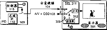
Fig. 3 illustrates for example operating position of display 301 of display that cost reduced.In order to reduce cost, the quantity of signal input part can be restricted to a for example radio frequency (RF) input, one-component video or S-video inputs and an AV signal input.This outstanding selection of the selector 280 of Fig. 2 and bypass capability allow display 301 to bring in monitor log and material non-record by single A/V input., this demonstration can advantageously utilize component video signal to connect, and outside connecting at signal, definite and control demonstration input is selected.For example, owing to can suppose that component video signal or S-VIDEO signal provide than the better displayed image quality of NTSC code signal, this component signal that is coupled to the component signal input can automatically cause the selection in component signal source.Therefore, when component and component signal were coupled to display 301 inputs 1 and 2 respectively, input controller had such logic, and its is predetermined selects component signal as with reference to input., this is imported selection automatically and can stop and monitor the digital record comprise to come from digital record and replay device 200 couplings of Fig. 2 and the signal of the special information displayed on screen of replay device., this is selected to be advantageously used in the remote control that starts AV signal with reference to input automatically and selects, for example the signal 103 on the input 2.By allowing or interrupt output coupled signal 104, and component signal 104 is carried out creative control, can on display 301, watch the signal that comprises information displayed on screen by digital record and replay device 200 couplings from IRD100.For example, the signal that the user selects non-record bit stream promptly to receive will cause the controller 115 of receiver 100 to begin to produce or export to have for example component signal 104 of S-VIDEO form.Selection to the recording picture signal that is used to show will cause controller 115 to interrupt producing or output component signals 104.Therefore, the controller 312 of monitor 301 is connected to the component signal input, to come the disappearance of detection signal 104 by signal 309, and making input selector 311 switch to AV signal 103 on the input 2 for example from the component input signal 104 on the input 1, input 2 is connected to the digital record among Fig. 2 and the selector 280 of replay device 200.
Claims (4)
1. digital record and replay device (200) are used for working with decoder (117), and this decoder (117) is used for the vision signal of digital compression, and said device comprises:
Transducer (251) is used for from the digitally coded Bitstream signal of recording medium playback;
Playback electronic installation (220) is connected to said transducer (251), and to handle said digitally coded Bitstream signal, the output signal bit that is used to decode with generation flows (221);
Status message generator (270) is used to produce display message (272) according to the working method of said digital record and replay device (200);
Device (280) is used for receiving the vision signal (102) from said output signal bit stream (221) decoding; With
Adder (275) is connected to said status message generator (270), is used for said display message (272) is added to said vision signal (102).
2. according to the digital record and the replay device (200) of claim 1, wherein, said receiving system (280) has first working method, and wherein said vision signal (102) is added display message; And second working method, wherein, the said display message of said vision signal (102) bypass is additional.
3. according to the digital record and the replay device (200) of claim 2, wherein, select said first working method at said device (200) opening power duration of work, when said digital record and replay device (200) powered-down, select said second working method.
4. according to the digital record and the replay device (200) of claim 2, further comprise device (A2), be used to select first and second working methods of said receiving system.
Applications Claiming Priority (4)
| Application Number | Priority Date | Filing Date | Title |
|---|---|---|---|
| US383495P | 1995-09-15 | 1995-09-15 | |
| US60/003,834 | 1995-09-15 | ||
| GB9603332.9 | 1996-02-14 | ||
| GBGB9603332.9A GB9603332D0 (en) | 1996-02-14 | 1996-02-14 | Interface for digital recorder and display |
Publications (2)
| Publication Number | Publication Date |
|---|---|
| CN1201579A CN1201579A (en) | 1998-12-09 |
| CN1096180C true CN1096180C (en) | 2002-12-11 |
Family
ID=26308735
Family Applications (5)
| Application Number | Title | Priority Date | Filing Date |
|---|---|---|---|
| CN96197988A Expired - Lifetime CN1113529C (en) | 1995-09-15 | 1996-09-13 | Enhanced display system on screen |
| CN96197982A Expired - Lifetime CN1107407C (en) | 1995-09-15 | 1996-09-13 | Displaying timer for screen |
| CN96197939A Pending CN1200859A (en) | 1995-09-15 | 1996-09-13 | On-screen displaying insertion |
| CN96197981A Expired - Lifetime CN1096180C (en) | 1995-09-15 | 1996-09-13 | Digital video and interface of display |
| CN96197954A Pending CN1200858A (en) | 1995-09-15 | 1996-09-13 | Simplified input selector for video signals |
Family Applications Before (3)
| Application Number | Title | Priority Date | Filing Date |
|---|---|---|---|
| CN96197988A Expired - Lifetime CN1113529C (en) | 1995-09-15 | 1996-09-13 | Enhanced display system on screen |
| CN96197982A Expired - Lifetime CN1107407C (en) | 1995-09-15 | 1996-09-13 | Displaying timer for screen |
| CN96197939A Pending CN1200859A (en) | 1995-09-15 | 1996-09-13 | On-screen displaying insertion |
Family Applications After (1)
| Application Number | Title | Priority Date | Filing Date |
|---|---|---|---|
| CN96197954A Pending CN1200858A (en) | 1995-09-15 | 1996-09-13 | Simplified input selector for video signals |
Country Status (12)
| Country | Link |
|---|---|
| US (1) | US7239793B2 (en) |
| EP (5) | EP0850544B1 (en) |
| JP (9) | JP3963949B2 (en) |
| KR (5) | KR100419329B1 (en) |
| CN (5) | CN1113529C (en) |
| AU (5) | AU7071296A (en) |
| BR (4) | BR9610529B1 (en) |
| DE (4) | DE69623025T2 (en) |
| ES (1) | ES2140898T3 (en) |
| MX (4) | MX9802031A (en) |
| TW (3) | TW387194B (en) |
| WO (5) | WO1997010680A1 (en) |
Families Citing this family (26)
| Publication number | Priority date | Publication date | Assignee | Title |
|---|---|---|---|---|
| GB9603332D0 (en) * | 1996-02-14 | 1996-04-17 | Thomson Consumer Electronics | Interface for digital recorder and display |
| JP3577845B2 (en) * | 1996-07-25 | 2004-10-20 | 松下電器産業株式会社 | TV monitor device |
| JPH10313443A (en) * | 1997-05-13 | 1998-11-24 | Matsushita Electric Ind Co Ltd | Digital signal recording and reproducing device |
| CN1131519C (en) | 1997-09-25 | 2003-12-17 | 日本胜利株式会社 | Information recording system and control method thereof |
| AU766795B2 (en) * | 1998-02-04 | 2003-10-23 | Thomson Licensing S.A. | Digital baseband interface for a DVD player |
| JPH11225292A (en) * | 1998-02-04 | 1999-08-17 | Sony Corp | Digital broadcast receiver and reception method |
| US7068920B1 (en) | 1998-02-04 | 2006-06-27 | Thomson Licensing | Digital baseband interface for a DVD player |
| KR100261111B1 (en) * | 1998-05-06 | 2000-07-01 | 윤종용 | Method of displaying system device operation of ieee 1394 network system |
| DE19833309B4 (en) * | 1998-07-24 | 2004-11-25 | Grundig Ag | TV receiver with onscreen display |
| US7865929B1 (en) | 1998-11-12 | 2011-01-04 | Sony Corporation | Receiving apparatus of digital broadcasting and display method of recording program associated information |
| ATE397351T1 (en) * | 1999-05-11 | 2008-06-15 | Koninkl Philips Electronics Nv | SET-TOP BOX THAT ALLOWS RECORDING BY A VIDEO RECORDING APPARATUS OF A TELEVISION PROGRAM SHOWN ON A TELEVISION SYSTEM |
| CN1189029C (en) * | 1999-05-11 | 2005-02-09 | 皇家菲利浦电子有限公司 | Reproducing arrangement for supplying on-screen display information to analog connection means in digital mode of information |
| DE60001834T2 (en) * | 1999-07-15 | 2003-12-24 | Thomson Licensing Sa | METHOD AND DEVICE FOR PROVIDING SCREEN DISPLAY FOR A MULTICOLORIMETRY RECEIVER |
| US7212250B1 (en) | 1999-07-15 | 2007-05-01 | Thomson Licensing | Method and apparatus for providing on-screen displays for a multi-colorimetry receiver |
| US6418273B1 (en) | 1999-09-07 | 2002-07-09 | The Original San Francisco Toymakers | Video compact disc player |
| US20030099293A1 (en) * | 1999-12-15 | 2003-05-29 | Shigeyuki Okada | Image reproducing method, and image processing method, and image reproducing device, image processing device, and television receiver capable of using the methods |
| KR100712777B1 (en) * | 2000-01-19 | 2007-04-30 | 엘지전자 주식회사 | Method for transmitting and processing an on screen display data |
| US6925246B1 (en) | 2000-07-05 | 2005-08-02 | Steinbeck Cannery, Llc | Television recorder having a removeable hard disk drive |
| JP3548136B2 (en) | 2001-06-01 | 2004-07-28 | 三洋電機株式会社 | Image processing device |
| US7260307B2 (en) | 2001-12-14 | 2007-08-21 | Thomson Licensing | Method and system for generating a user interface for digital televisions |
| US20060133779A1 (en) | 2003-02-05 | 2006-06-22 | Koninklijke Philips Electronics N.V. | Video recording apparatus and method of operation therefor |
| KR100633098B1 (en) * | 2004-11-23 | 2006-10-11 | 삼성전자주식회사 | Display apparatus capable of setting optimized external input and method thereof |
| US7657829B2 (en) * | 2005-01-20 | 2010-02-02 | Microsoft Corporation | Audio and video buffer synchronization based on actual output feedback |
| EP1869876B1 (en) * | 2005-04-15 | 2016-04-13 | Thomson Licensing | High-definition and single-definition digital television decoder |
| JP2007074608A (en) * | 2005-09-09 | 2007-03-22 | Hitachi Ltd | Reproducing apparatus and reproducing method |
| KR102256642B1 (en) * | 2014-12-04 | 2021-05-27 | 삼성전자주식회사 | Apparatus for transmiting and receiving message and method for transmiting and receiving message |
Citations (4)
| Publication number | Priority date | Publication date | Assignee | Title |
|---|---|---|---|---|
| EP0220007A2 (en) * | 1985-10-07 | 1987-04-29 | Yamaha Corporation | Synchronizing circuit for a video disc playback device |
| US5097348A (en) * | 1988-02-29 | 1992-03-17 | Casio Computer Co., Ltd. | Image data recording/reproducing apparatus including superimposing function |
| EP0529834A1 (en) * | 1991-08-14 | 1993-03-03 | Pioneer Electronic Corporation | Recorded information reproducing device |
| CN1100581A (en) * | 1993-06-02 | 1995-03-22 | 汤姆森消费电子有限公司 | On-screen display generator |
Family Cites Families (39)
| Publication number | Priority date | Publication date | Assignee | Title |
|---|---|---|---|---|
| US4118669A (en) | 1976-10-15 | 1978-10-03 | Premier Cablevision, Limited | Remote disconnect-reconnect tap for cable television systems |
| DE3104843A1 (en) | 1981-02-11 | 1982-08-19 | Licentia Patent-Verwaltungs-Gmbh, 6000 Frankfurt | VIDEO RECORDER WITH SEVERAL CONTROLS |
| US4510003A (en) * | 1981-12-07 | 1985-04-09 | Dayco Corporation | Method of making an endless power transmission belt construction |
| US5508815A (en) | 1981-12-14 | 1996-04-16 | Smart Vcr Limited Partnership | Schedule display system for video recorder programming |
| US4405946A (en) * | 1982-02-16 | 1983-09-20 | Rca Corporation | Television signal converting apparatus providing an on-screen tuning display |
| US4460918A (en) * | 1982-07-14 | 1984-07-17 | Zenith Electronics Corporation | Automatic switching circuit for a dual mode television receiver |
| US4660073A (en) * | 1984-12-18 | 1987-04-21 | Eastman Kodak Company | Video apparatus for selectively processing either composite or component color video signals |
| US4734791A (en) | 1986-04-11 | 1988-03-29 | Ampex Corporation | Video tape recorder having status display mode |
| US4821122A (en) | 1987-01-21 | 1989-04-11 | Rca Licensing Corporation | TV receiver with automatic RF/baseband signal |
| JP2638815B2 (en) * | 1987-07-28 | 1997-08-06 | ソニー株式会社 | Disc playback device |
| JPH07118798B2 (en) | 1988-02-29 | 1995-12-18 | パイオニア株式会社 | Image information recording and reproducing method |
| NL9000130A (en) * | 1990-01-19 | 1990-05-01 | Philips Nv | VIDEO SYSTEM. |
| JP2949747B2 (en) * | 1990-01-21 | 1999-09-20 | ソニー株式会社 | Information input device |
| US5410437A (en) | 1991-03-31 | 1995-04-25 | Sony Corporation | Apparatus for recording and/or reproducing an information signal, a PCM signal and a video signal in a helical track on a recorded medium and superimposing character signals on the video signal |
| KR920020481A (en) | 1991-04-29 | 1992-11-21 | 강진구 | How to automatically change the recording speed of your VCR |
| US5151783A (en) | 1991-06-05 | 1992-09-29 | Faroudja Y C | Digital television with enhancement |
| AT399629B (en) | 1992-02-25 | 1995-06-26 | Koninkl Philips Electronics Nv | SYSTEM FOR RECORDING AND PLAYING BACK IMAGE SIGNALS IN WHICH SIGNAL SIGNALS ARE TOUCHED |
| JP2876880B2 (en) | 1992-03-31 | 1999-03-31 | 松下電器産業株式会社 | Video information equipment |
| JP2597159Y2 (en) * | 1992-04-28 | 1999-06-28 | 三洋電機株式会社 | Character position correction circuit on the screen |
| US5377051A (en) * | 1993-01-13 | 1994-12-27 | Hitachi America, Ltd. | Digital video recorder compatible receiver with trick play image enhancement |
| JP3282260B2 (en) | 1993-01-18 | 2002-05-13 | ソニー株式会社 | Image reproducing apparatus and method |
| US5428400A (en) * | 1993-01-29 | 1995-06-27 | Thomson Consumer Electronics, Inc. | Enabling a display of closed captioning status upon detecting a code of a proper subset of closed-caption data codes |
| US5515173A (en) * | 1993-03-05 | 1996-05-07 | Gemstar Developement Corporation | System and method for automatically recording television programs in television systems with tuners external to video recorders |
| JPH06319110A (en) | 1993-05-07 | 1994-11-15 | Hitachi Ltd | Digital signal receiver |
| JPH0779411A (en) | 1993-09-06 | 1995-03-20 | Sony Corp | Video signal reproduction method, picture signal reproduction device and picture signal recording medium |
| US5729651A (en) | 1994-04-18 | 1998-03-17 | Matsushita Electric Industrial Co., Ltd. | Video signal with super impose character data reproducing apparatus |
| JP3339210B2 (en) | 1994-07-04 | 2002-10-28 | ソニー株式会社 | Playback device |
| US5841987A (en) | 1994-08-19 | 1998-11-24 | Thomson Consumer Electronics, Inc. | Simple bus and interface system for consumer digital equipment |
| JP3644455B2 (en) * | 1994-09-29 | 2005-04-27 | ソニー株式会社 | Program information broadcasting system, program information display method and receiving apparatus |
| US5815634A (en) * | 1994-09-30 | 1998-09-29 | Cirrus Logic, Inc. | Stream synchronization method and apparatus for MPEG playback system |
| US5598352A (en) * | 1994-09-30 | 1997-01-28 | Cirrus Logic, Inc. | Method and apparatus for audio and video synchronizing in MPEG playback systems |
| US5978546A (en) | 1995-01-17 | 1999-11-02 | Hitachi, Ltd. | Digital/analog compatible video tape recorder |
| JP3348339B2 (en) | 1995-08-02 | 2002-11-20 | ソニー株式会社 | Data recording method and device, data reproducing method and device |
| US6363213B1 (en) * | 1996-02-14 | 2002-03-26 | Thomson Licensing S.A. | Interface for digital recorder and display |
| US6177961B1 (en) * | 1996-02-14 | 2001-01-23 | Thomson Licensing S.A. | Television system with display of VCR mode |
| US6034738A (en) * | 1996-02-14 | 2000-03-07 | Thomson Consumer Electronics, Inc. | On-screen display timing |
| JP3752298B2 (en) | 1996-04-01 | 2006-03-08 | オリンパス株式会社 | Image editing device |
| US5974221A (en) | 1996-11-01 | 1999-10-26 | Mitsubishi Denki Kabushiki Kaisha | Playback device |
| TW496087B (en) * | 2000-08-29 | 2002-07-21 | Myson Technology Inc Taiwan | Device and method for rotating on screen display characters |
-
1996
- 1996-09-13 KR KR10-1998-0701895A patent/KR100419329B1/en not_active IP Right Cessation
- 1996-09-13 BR BRPI9610529-1A patent/BR9610529B1/en not_active IP Right Cessation
- 1996-09-13 WO PCT/US1996/014731 patent/WO1997010680A1/en active IP Right Grant
- 1996-09-13 CN CN96197988A patent/CN1113529C/en not_active Expired - Lifetime
- 1996-09-13 EP EP96932220A patent/EP0850544B1/en not_active Expired - Lifetime
- 1996-09-13 WO PCT/US1996/014693 patent/WO1997010679A1/en active IP Right Grant
- 1996-09-13 JP JP51212297A patent/JP3963949B2/en not_active Expired - Fee Related
- 1996-09-13 JP JP51213897A patent/JP4150072B2/en not_active Expired - Lifetime
- 1996-09-13 KR KR10-1998-0701892A patent/KR100412519B1/en not_active IP Right Cessation
- 1996-09-13 WO PCT/US1996/014733 patent/WO1997010682A1/en not_active Application Discontinuation
- 1996-09-13 BR BR9610539A patent/BR9610539A/en not_active IP Right Cessation
- 1996-09-13 JP JP51214397A patent/JP3789939B2/en not_active Expired - Lifetime
- 1996-09-13 KR KR1019980701896A patent/KR100551543B1/en not_active IP Right Cessation
- 1996-09-13 EP EP96930873A patent/EP0850541B1/en not_active Revoked
- 1996-09-13 CN CN96197982A patent/CN1107407C/en not_active Expired - Lifetime
- 1996-09-13 ES ES96932220T patent/ES2140898T3/en not_active Expired - Lifetime
- 1996-09-13 DE DE69623025T patent/DE69623025T2/en not_active Expired - Lifetime
- 1996-09-13 BR BR9610521A patent/BR9610521A/en not_active IP Right Cessation
- 1996-09-13 DE DE69606185T patent/DE69606185T2/en not_active Expired - Lifetime
- 1996-09-13 AU AU70712/96A patent/AU7071296A/en not_active Abandoned
- 1996-09-13 DE DE69618796T patent/DE69618796T2/en not_active Expired - Lifetime
- 1996-09-13 WO PCT/US1996/014738 patent/WO1997010678A1/en active IP Right Grant
- 1996-09-13 AU AU71093/96A patent/AU7109396A/en not_active Abandoned
- 1996-09-13 DE DE69601583T patent/DE69601583T2/en not_active Revoked
- 1996-09-13 AU AU71592/96A patent/AU7159296A/en not_active Abandoned
- 1996-09-13 WO PCT/US1996/014732 patent/WO1997010681A1/en active IP Right Grant
- 1996-09-13 CN CN96197939A patent/CN1200859A/en active Pending
- 1996-09-13 EP EP96931570A patent/EP0850542B1/en not_active Expired - Lifetime
- 1996-09-13 AU AU70713/96A patent/AU7071396A/en not_active Abandoned
- 1996-09-13 CN CN96197981A patent/CN1096180C/en not_active Expired - Lifetime
- 1996-09-13 BR BR9610549A patent/BR9610549A/en not_active IP Right Cessation
- 1996-09-13 EP EP96931571A patent/EP0850543B1/en not_active Expired - Lifetime
- 1996-09-13 CN CN96197954A patent/CN1200858A/en active Pending
- 1996-09-13 EP EP96933017A patent/EP0853858A1/en not_active Withdrawn
- 1996-09-13 KR KR10-1998-0701893A patent/KR100421067B1/en not_active IP Right Cessation
- 1996-09-13 KR KR10-1998-0701894A patent/KR100417662B1/en not_active IP Right Cessation
- 1996-09-13 JP JP51214097A patent/JP4073037B2/en not_active Expired - Lifetime
- 1996-09-13 JP JP51213997A patent/JP4152436B2/en not_active Expired - Lifetime
- 1996-09-13 AU AU69774/96A patent/AU6977496A/en not_active Abandoned
- 1996-10-03 TW TW085112102A patent/TW387194B/en not_active IP Right Cessation
- 1996-10-08 TW TW085112264A patent/TW382690B/en not_active IP Right Cessation
- 1996-10-11 TW TW085112389A patent/TW324095B/en not_active IP Right Cessation
-
1998
- 1998-03-13 MX MX9802031A patent/MX9802031A/en unknown
- 1998-03-13 MX MX9802035A patent/MX9802035A/en unknown
- 1998-03-13 MX MX9802032A patent/MX9802032A/en unknown
- 1998-03-13 MX MX9802033A patent/MX9802033A/en unknown
-
2001
- 2001-05-24 US US09/864,672 patent/US7239793B2/en not_active Expired - Fee Related
-
2006
- 2006-02-13 JP JP2006035220A patent/JP2006191664A/en active Pending
-
2007
- 2007-08-21 JP JP2007214237A patent/JP4601010B2/en not_active Expired - Lifetime
- 2007-09-04 JP JP2007228511A patent/JP4601011B2/en not_active Expired - Lifetime
- 2007-11-21 JP JP2007301451A patent/JP2008104218A/en active Pending
Patent Citations (4)
| Publication number | Priority date | Publication date | Assignee | Title |
|---|---|---|---|---|
| EP0220007A2 (en) * | 1985-10-07 | 1987-04-29 | Yamaha Corporation | Synchronizing circuit for a video disc playback device |
| US5097348A (en) * | 1988-02-29 | 1992-03-17 | Casio Computer Co., Ltd. | Image data recording/reproducing apparatus including superimposing function |
| EP0529834A1 (en) * | 1991-08-14 | 1993-03-03 | Pioneer Electronic Corporation | Recorded information reproducing device |
| CN1100581A (en) * | 1993-06-02 | 1995-03-22 | 汤姆森消费电子有限公司 | On-screen display generator |
Also Published As
Similar Documents
| Publication | Publication Date | Title |
|---|---|---|
| CN1096180C (en) | Digital video and interface of display | |
| US6034738A (en) | On-screen display timing | |
| WO1997010682A9 (en) | Upgradable on-screen display system | |
| US6177961B1 (en) | Television system with display of VCR mode | |
| US6363213B1 (en) | Interface for digital recorder and display | |
| US8364014B2 (en) | Upgradable on screen display system | |
| CN100515063C (en) | Simplified vision signal input selector | |
| EP1261216B1 (en) | Receiver device |
Legal Events
| Date | Code | Title | Description |
|---|---|---|---|
| C06 | Publication | ||
| PB01 | Publication | ||
| C10 | Entry into substantive examination | ||
| SE01 | Entry into force of request for substantive examination | ||
| C14 | Grant of patent or utility model | ||
| GR01 | Patent grant | ||
| CX01 | Expiry of patent term |
Granted publication date: 20021211 |
|
| EXPY | Termination of patent right or utility model |