CN109582112B - Utility portal for managing demand response events - Google Patents
Utility portal for managing demand response events Download PDFInfo
- Publication number
- CN109582112B CN109582112B CN201811201918.7A CN201811201918A CN109582112B CN 109582112 B CN109582112 B CN 109582112B CN 201811201918 A CN201811201918 A CN 201811201918A CN 109582112 B CN109582112 B CN 109582112B
- Authority
- CN
- China
- Prior art keywords
- energy
- event
- demand response
- utility
- response event
- Prior art date
- Legal status (The legal status is an assumption and is not a legal conclusion. Google has not performed a legal analysis and makes no representation as to the accuracy of the status listed.)
- Active
Links
Images


Classifications
-
- G—PHYSICS
- G06—COMPUTING; CALCULATING OR COUNTING
- G06Q—INFORMATION AND COMMUNICATION TECHNOLOGY [ICT] SPECIALLY ADAPTED FOR ADMINISTRATIVE, COMMERCIAL, FINANCIAL, MANAGERIAL OR SUPERVISORY PURPOSES; SYSTEMS OR METHODS SPECIALLY ADAPTED FOR ADMINISTRATIVE, COMMERCIAL, FINANCIAL, MANAGERIAL OR SUPERVISORY PURPOSES, NOT OTHERWISE PROVIDED FOR
- G06Q30/00—Commerce
- G06Q30/02—Marketing; Price estimation or determination; Fundraising
- G06Q30/0201—Market modelling; Market analysis; Collecting market data
- G06Q30/0202—Market predictions or forecasting for commercial activities
-
- G—PHYSICS
- G06—COMPUTING; CALCULATING OR COUNTING
- G06F—ELECTRIC DIGITAL DATA PROCESSING
- G06F16/00—Information retrieval; Database structures therefor; File system structures therefor
- G06F16/90—Details of database functions independent of the retrieved data types
- G06F16/95—Retrieval from the web
- G06F16/955—Retrieval from the web using information identifiers, e.g. uniform resource locators [URL]
-
- G—PHYSICS
- G06—COMPUTING; CALCULATING OR COUNTING
- G06Q—INFORMATION AND COMMUNICATION TECHNOLOGY [ICT] SPECIALLY ADAPTED FOR ADMINISTRATIVE, COMMERCIAL, FINANCIAL, MANAGERIAL OR SUPERVISORY PURPOSES; SYSTEMS OR METHODS SPECIALLY ADAPTED FOR ADMINISTRATIVE, COMMERCIAL, FINANCIAL, MANAGERIAL OR SUPERVISORY PURPOSES, NOT OTHERWISE PROVIDED FOR
- G06Q50/00—Systems or methods specially adapted for specific business sectors, e.g. utilities or tourism
- G06Q50/06—Electricity, gas or water supply
-
- H—ELECTRICITY
- H04—ELECTRIC COMMUNICATION TECHNIQUE
- H04L—TRANSMISSION OF DIGITAL INFORMATION, e.g. TELEGRAPHIC COMMUNICATION
- H04L63/00—Network architectures or network communication protocols for network security
- H04L63/08—Network architectures or network communication protocols for network security for authentication of entities
-
- H—ELECTRICITY
- H04—ELECTRIC COMMUNICATION TECHNIQUE
- H04L—TRANSMISSION OF DIGITAL INFORMATION, e.g. TELEGRAPHIC COMMUNICATION
- H04L63/00—Network architectures or network communication protocols for network security
- H04L63/10—Network architectures or network communication protocols for network security for controlling access to devices or network resources
- H04L63/102—Entity profiles
-
- H—ELECTRICITY
- H04—ELECTRIC COMMUNICATION TECHNIQUE
- H04W—WIRELESS COMMUNICATION NETWORKS
- H04W12/00—Security arrangements; Authentication; Protecting privacy or anonymity
- H04W12/06—Authentication
-
- F—MECHANICAL ENGINEERING; LIGHTING; HEATING; WEAPONS; BLASTING
- F24—HEATING; RANGES; VENTILATING
- F24F—AIR-CONDITIONING; AIR-HUMIDIFICATION; VENTILATION; USE OF AIR CURRENTS FOR SCREENING
- F24F11/00—Control or safety arrangements
- F24F11/30—Control or safety arrangements for purposes related to the operation of the system, e.g. for safety or monitoring
- F24F11/46—Improving electric energy efficiency or saving
-
- F—MECHANICAL ENGINEERING; LIGHTING; HEATING; WEAPONS; BLASTING
- F24—HEATING; RANGES; VENTILATING
- F24F—AIR-CONDITIONING; AIR-HUMIDIFICATION; VENTILATION; USE OF AIR CURRENTS FOR SCREENING
- F24F11/00—Control or safety arrangements
- F24F11/50—Control or safety arrangements characterised by user interfaces or communication
- F24F11/56—Remote control
- F24F11/58—Remote control using Internet communication
-
- Y—GENERAL TAGGING OF NEW TECHNOLOGICAL DEVELOPMENTS; GENERAL TAGGING OF CROSS-SECTIONAL TECHNOLOGIES SPANNING OVER SEVERAL SECTIONS OF THE IPC; TECHNICAL SUBJECTS COVERED BY FORMER USPC CROSS-REFERENCE ART COLLECTIONS [XRACs] AND DIGESTS
- Y02—TECHNOLOGIES OR APPLICATIONS FOR MITIGATION OR ADAPTATION AGAINST CLIMATE CHANGE
- Y02B—CLIMATE CHANGE MITIGATION TECHNOLOGIES RELATED TO BUILDINGS, e.g. HOUSING, HOUSE APPLIANCES OR RELATED END-USER APPLICATIONS
- Y02B70/00—Technologies for an efficient end-user side electric power management and consumption
- Y02B70/30—Systems integrating technologies related to power network operation and communication or information technologies for improving the carbon footprint of the management of residential or tertiary loads, i.e. smart grids as climate change mitigation technology in the buildings sector, including also the last stages of power distribution and the control, monitoring or operating management systems at local level
- Y02B70/3225—Demand response systems, e.g. load shedding, peak shaving
-
- Y—GENERAL TAGGING OF NEW TECHNOLOGICAL DEVELOPMENTS; GENERAL TAGGING OF CROSS-SECTIONAL TECHNOLOGIES SPANNING OVER SEVERAL SECTIONS OF THE IPC; TECHNICAL SUBJECTS COVERED BY FORMER USPC CROSS-REFERENCE ART COLLECTIONS [XRACs] AND DIGESTS
- Y04—INFORMATION OR COMMUNICATION TECHNOLOGIES HAVING AN IMPACT ON OTHER TECHNOLOGY AREAS
- Y04S—SYSTEMS INTEGRATING TECHNOLOGIES RELATED TO POWER NETWORK OPERATION, COMMUNICATION OR INFORMATION TECHNOLOGIES FOR IMPROVING THE ELECTRICAL POWER GENERATION, TRANSMISSION, DISTRIBUTION, MANAGEMENT OR USAGE, i.e. SMART GRIDS
- Y04S20/00—Management or operation of end-user stationary applications or the last stages of power distribution; Controlling, monitoring or operating thereof
- Y04S20/20—End-user application control systems
- Y04S20/222—Demand response systems, e.g. load shedding, peak shaving
-
- Y—GENERAL TAGGING OF NEW TECHNOLOGICAL DEVELOPMENTS; GENERAL TAGGING OF CROSS-SECTIONAL TECHNOLOGIES SPANNING OVER SEVERAL SECTIONS OF THE IPC; TECHNICAL SUBJECTS COVERED BY FORMER USPC CROSS-REFERENCE ART COLLECTIONS [XRACs] AND DIGESTS
- Y04—INFORMATION OR COMMUNICATION TECHNOLOGIES HAVING AN IMPACT ON OTHER TECHNOLOGY AREAS
- Y04S—SYSTEMS INTEGRATING TECHNOLOGIES RELATED TO POWER NETWORK OPERATION, COMMUNICATION OR INFORMATION TECHNOLOGIES FOR IMPROVING THE ELECTRICAL POWER GENERATION, TRANSMISSION, DISTRIBUTION, MANAGEMENT OR USAGE, i.e. SMART GRIDS
- Y04S40/00—Systems for electrical power generation, transmission, distribution or end-user application management characterised by the use of communication or information technologies, or communication or information technology specific aspects supporting them
- Y04S40/20—Information technology specific aspects, e.g. CAD, simulation, modelling, system security
Abstract
The invention relates to a utility portal for managing demand response events. Various utility portals are disclosed that enable utility companies to manage demand response events. The disclosed utility portal includes a number of different options for enabling a utility company to transmit and receive information to and from an energy management system. The energy management system may host a portal and may execute a demand response event via the intelligent network connection device based on information provided by the utility company.
Description
Description of the cases
The application belongs to divisional application of Chinese patent application 201480027888.6 with application date 2014, 03 and 07.
This patent application is a continuation-in-part application of U.S. patent application No. 13/842,213 (attorney docket nos 0253-US), filed on 15/3/2013, the disclosure of which is incorporated herein by reference in its entirety.
This patent specification relates to utility portals for managing demand response events. More particularly, the present description relates to a user interface that enables a utility company to communicate information to an energy management system that may implement energy transfer techniques for a structural community having ambient cooling systems controlled by various communities of network-connected thermostats.
Background
Utilities face the ongoing challenge of consistently meeting demand for electricity. Facilities for generating electricity are generally well suited to supplying a constant amount of electricity. However, consumer demand for electricity is often quite reversed, as the aggregate electricity demand changes significantly over the course of the delay. Daily variation results in one or more 'peak' demand times or periods in which demand on the utility is greatest, and 'off-peak' demand times or periods in which demand on the utility is reduced.
Changes in demand over the course of a day may be affected by many factors such as weather and lifestyle. For example, during the summer season, demand generally tends to increase as outdoor temperatures increase to levels considered uncomfortable, as consumers increase their use of high-consumption appliances such as air conditioning systems. Demand also generally tends to change based on work habits, where demand is at a peak before people are on duty and again after people are off duty. During certain points of the year, such as during very hot weather, demand can reach extreme peaks.
Utility companies have various options for dealing with variable demand for energy. For example, it may increase its ability to meet higher peak demands by building additional power plants. However, the cost of doing so is often very high, and building such plants is often inefficient because the added capacity is only used for a short period of the year. It may purchase additional capacity from other utility companies or energy providers, but doing so is also costly, as such companies may charge additional fees, and energy transfer from those other companies is often less efficient. Instead of increasing supply, utility companies can also address peak demand by reducing demand via load shedding.
Load shedding is a technique in which a utility company reduces the amount of energy required by its customers during periods of peak demand. Various load shedding techniques are now in use, most of which are based on the utility company directly controlling the cooling system of its customers. During such peak demand periods, the utility company controls the cooling system to reduce its energy demand. Such events, which may often occur in very hot weather from afternoon to evening, and have a duration in the general range of two to six hours, are referred to herein by various different names such as load shedding events, load shifting events, and demand response events. The goal of a utility company in performing such an event is not necessarily to reduce the total amount of energy consumed throughout the day, but rather to reduce the peak demand during that particular two to six hour interval, i.e., the load shedding interval or the demand response interval. Typically, the end result is that the energy that would have been consumed during the load shedding interval is instead consumed within hours after the load shedding interval, as the cooling system of the participating home operates to restore its cooler normal setpoint temperature. Such control, of course, often creates an inconvenience to consumers who sign up to participate in such 'demand response programs' because their cooling systems may not cool their homes as expected. However, in return for this inconvenience, consumers are often given certain benefits, such as more benefits for energy consumed outside of peak demand periods.
One common load shedding technique, often referred to as direct load control, involves periodic on-off cycling of power to the cooling system of each participating consumer under the direct control of the utility during load shedding periods. In this method, a remotely controllable switch is installed on each customer's cooling system and is operable to disconnect power to the cooling system under the direct control of the utility company. The power to the cooling system may then be directly controlled by the utility company such that it is shut down for regular fixed time intervals during periods of peak demand. However, consumers may express some degree of dislikeness towards such technologies, as direct load control results in a lack of control of their cooling systems by the consumer, and often results in indoor temperatures that are perceived as uncomfortable by the consumer. Defects in the communication link between the utility company and the switch can exacerbate the problem, with a loss command from the utility company to the switch to reconnect power to the cooling system causing the cooling system to undesirably remain in the disconnected state. Such problems have led some consumers to attempt to eliminate control of their cooling system by bypassing the remote switch while still gaining the benefit of participating in the demand response program. As a result, while such "cheaters" may acquire their desired individual cooling system control, the effectiveness of the overall demand response program may be compromised.
Another known load shedding technique involves remote control of the setpoint temperature of each participating customer's thermostat by the utility, wherein the utility company sends a public recall (setback) value to the participating customer's thermostat. During the load shedding period, the participating thermostats will control the indoor temperature to a temperature set point value that is higher than the normal dispatch temperature set point value by a rollback amount. This control by the utility company will typically result in a less comfortable ambient temperature than the consumer would otherwise experience, but provides the benefits of both energy and cost savings. While direct on/off cycling of power to a cooling system relative to utility offers the potential to increase comfort and acceptance, this technique may have drawbacks including lack of control by the consumer and the ability of the utility to set the turnback value to whatever value the utility deems appropriate. Furthermore, using a single recall value for all consumers fails to recognize differences in the feel of comfort, differences in the thermal characteristics of the home, differences in the cooling capacity of the cooling system, and other differences between the bases of participating customers.
U.S. patent application No. 2012/0053745 to Howard Ng discusses a system and method for establishing load control during a load shedding event. Specifically, Ng discusses a technique that allows a customer or utility to control the maximum temperature rise under a direct load control procedure. The customer may set a comfort range on his thermostat that indicates a temperature range from the desired temperature at which the customer is comfortable. During a load shedding event, in a hot weather example, a switch on the space conditioning load is activated such that the space conditioning load undergoes direct load control (i.e., a fixed width duty cycle). The space conditioning load undergoes direct load control until the indoor temperature exceeds the upper limit value of the comfort range, at which point control will be transferred from direct load control to temperature turn-back control.
While the load shedding method described above provides a utility option that will address peak energy demands, the tools to do so are limited. What is needed is a user interface that is intuitive, providing flexibility in managing demand response events and information about how much energy should be transferred in a demand response event so that a utility company can better manage the demand response event.
Disclosure of Invention
Various utility portals are disclosed herein that enable utility companies to manage demand response events. The disclosed utility portal includes a number of different options for enabling a utility company to transmit and receive information to and from an energy management system. The energy management system may host a portal and may execute a demand response event via the intelligent network connection device based on information provided by the utility company.
A utility portal interface for use by utility companies for managing demand response events is disclosed. The utility portal may include a customer management module operable to enable a utility operator to assign at least one parameter to each energy consumer registered to participate in the demand response program. The at least one parameter includes a plurality of groups, and each utility approved energy consumer is assigned to one of the groups. The utility portal includes a scheduling module operable to enable a utility operator to define at least one attribute of a future demand response event. The at least one attribute includes one or more of a date on which a future demand response event will begin, a demand response event period, and one or more of a group. The scheduling module is further operable to display the one or more groups and information associated with each group including an indication as to whether the group is available for inclusion in future demand response events. The scheduling module is further operable to enable the utility user to selectively include one or more of the available groups as attributes of a future demand response event.
A method for enabling a utility company to request a demand response event using a utility portal is disclosed. The utility portal may be hosted by an energy management system that manages demand response events for a population of structures having ambient cooling systems controlled by a respective population of network-connected thermostats. The method includes displaying a parameter definition region that enables a utility company to specify a plurality of parameters for a demand response request, the parameters including an energy reduction amount, a date, and a time period. The method includes receiving parameter data specifying an amount of energy reduction, a date, and a time period, and receiving a request for a demand response based on the received parameter data. The method includes displaying a demand response solution in a solution area of the utility portal in response to the received request, and receiving a confirmation to execute the demand response solution.
A method for enabling a utility company to request a demand response event using a utility portal is also disclosed. The utility portal may be hosted by an energy management system that manages demand response events for a population of structures having ambient cooling systems controlled by a respective population of network-connected thermostats. The method includes displaying a plurality of selectable modules including at least one scheduling module and a suggestion module. A number indicating the number of suggested demand response events is displayed in a tag associated with the suggestion module. In response to receiving a user selection of a suggestion module, one or more suggested demand response events are displayed in a suggestion region of the utility portal, each suggested demand response event including event-specific information. The method further includes enabling the utility company to select any one or more of the displayed proposed demand response events and receiving instructions to begin each selected proposed demand response event.
For a fuller understanding of the nature and advantages of embodiments of the present invention, reference should be made to the following detailed description and accompanying drawings. Other aspects, objects, and advantages of the invention will be apparent from the drawings and from the detailed description that follows. However, the scope of the invention will be fully apparent from the recitation of the claims.
Drawings
FIG. 1 depicts a system for implementing a demand response program and event management according to an embodiment.
FIG. 2 illustrates an example of a smart-home environment within which a portion of a system for implementing a demand response program and event management may be implemented, according to an embodiment.
Fig. 3A illustrates an example of general device components that may be included in an intelligent network connection device, according to an embodiment.
Fig. 3B illustrates an intelligent network connection device with replaceable modules and a docking station, in accordance with an embodiment.
Fig. 3C illustrates a connection port and wire insertion sensing circuit of an intelligent network connection device according to an embodiment.
FIG. 4 illustrates a network-level view of an extensible device and service platform with which smart-home environments and systems for implementing demand response procedures and event management may be integrated, according to an embodiment.
FIG. 5 illustrates an abstract functional view of the extensible device and service platform of FIG. 4.
FIG. 6 is a block diagram of a special purpose computer system according to an embodiment.
FIG. 7 illustrates a process for implementing and managing a demand response program, according to an embodiment.
FIG. 8 illustrates a process for enrolling an energy consumer in a demand response program, according to an embodiment.
FIG. 9 illustrates a process for facilitating enrollment of an energy consumer in a demand response program via an electronic device associated with the energy consumer, according to an embodiment.
FIG. 10 illustrates a process for generating one or more metrics indicating an amount of energy that may be transferred by an energy consumer if the energy consumer registers and participates in a demand response program, according to an embodiment.
11A-11C depict graphical user interfaces of intelligent network-connected thermostats associated with identified energy consumers receiving and responding to registration requests, according to embodiments.
FIG. 12 illustrates a process for analyzing a number of factors to determine whether a registered energy consumer is eligible to participate in a particular DR event, according to an embodiment.
Fig. 13 illustrates a process for identifying registered energy consumers that will participate in a DR event, according to an embodiment.
FIG. 14 illustrates a process for managing energy consumption for energy consumers participating in an identification in a DR event, according to an embodiment.
FIG. 15 illustrates a process for managing DR events based on monitored aggregate energy transfers, according to an embodiment.
FIG. 16 illustrates a process for generating a demand response event implementation according to an embodiment.
Fig. 17A is an illustration of a DR event and associated period according to an embodiment.
Fig. 17B is an illustration of energy consumer initially scheduled setpoints and DR event modifications covering the time period described with reference to fig. 17A, according to an embodiment.
Fig. 18A is a diagram depicting a DR event interval energy reduction mechanism of setpoint change type, according to an embodiment.
Fig. 18B is a diagram depicting a DR event interval energy reduction mechanism of duty cycle change type, according to an embodiment.
Fig. 18C is a diagram depicting a DR event interval energy reduction mechanism of a combined setpoint/duty cycle change type, according to an embodiment.
Fig. 19 illustrates a process for determining whether pre-cooling is appropriate, according to an embodiment.
Fig. 20 illustrates a process for determining whether a retroactive DR event interval energy management mechanism is appropriate, according to an embodiment.
Fig. 21 illustrates a process for determining whether a duty cycle DR event interval energy management mechanism is appropriate, according to an embodiment.
FIG. 22 illustrates a process for determining whether post-event energy management is appropriate, according to an embodiment.
In particular, fig. 23 illustrates a process for generating one or more metrics indicative of an amount of energy that may be transferred by an energy consumer if a registered energy consumer participates in a demand response event, according to an embodiment.
Fig. 24A-24C illustrate simplified graphical user interfaces for presenting DR event notifications to energy consumers, according to embodiments.
Fig. 25A-25F illustrate simplified graphical user interfaces of schedules of setpoints associated with energy consumers that have agreed to participate in a DR event, according to embodiments.
Fig. 26A-26D illustrate simplified graphical user interfaces for responding to an immediate setpoint change during a DR event, according to embodiments.
Fig. 27 illustrates a process for learning user preferences indicated during a DR event according to an embodiment.
Fig. 28 illustrates a particular process for modifying a DR implementation profile based on user preferences indicated during a prior DR event, according to an embodiment.
FIG. 29A illustrates an I/O element including a utility portal summary according to an embodiment.
Fig. 29B illustrates an I/O element including a utility portal providing detailed energy consumer information, according to an embodiment.
Fig. 30A illustrates a process for determining whether an energy consumer has complied with participating in a DR event, according to an embodiment.
Fig. 30B illustrates a process for determining whether intervention of an HVAC lead indicates an attempt to eliminate DR programming, according to an embodiment.
Fig. 31A illustrates a process for managing energy management of energy according to a bilateral contract between an energy manager associated with an energy management system and a utility provider associated with a utility provider computing system, according to an embodiment.
Fig. 31B illustrates a process for managing energy management of energy according to market-based sales of energy reductions, according to an embodiment.
FIG. 32 illustrates a process for communicating and supplementing information from an energy consumption meter to a utility provider computing system via an energy management system, according to an embodiment.
33A-33E show multiple screen shots illustrating a demand response program enrollment process for an energy consumer having a network-connected device, in accordance with various embodiments.
34A and 34B show illustrative input/output (I/O) elements of a utility module having a customer module, in accordance with various embodiments.
34C-34G show illustrative I/O elements of a utility portal having a scheduling module, in accordance with various embodiments.
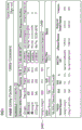
FIG. 35 shows illustrative content of a file downloaded from an energy management system, according to an embodiment.
FIG. 36A shows an illustrative example of a utility portal that provides a selection group based on an estimated energy savings, according to some embodiments.
36B-36D each illustrate greatly simplified I/O elements of a utility portal showing different graphs based on which one or more groups are selected, according to various embodiments.
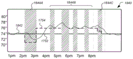
36E-36G each illustrate I/O elements of a utility portal showing an energy demand profile representing a combination of real-time energy consumption and predicted energy consumption, in accordance with various embodiments.
FIG. 37 shows illustrative I/O elements of a utility portal with a request module, according to an embodiment.
FIG. 38 shows illustrative I/O elements of a utility portal with a suggestion module, according to an embodiment.
Detailed Description
Embodiments discussed herein relate generally to techniques for managing demand response programs and events, and in particular, to utility portals that enable utility companies to manage demand response events. The entities in the system for managing demand response programs and events typically include utility providers that provide electricity or other forms of energy from a power source (e.g., a generator) to individual homes or businesses. Individuals typically pay for the amount of energy they consume periodically (e.g., every month). In many embodiments, the energy management system is disposed between the utility provider and the individual. The energy management system operates to intelligently and efficiently shift the energy consumption of an individual from one particular time period to other time periods. Such energy transfers are often performed to transfer energy consumption from periods of high energy cost to periods of low energy cost. In the case of a DR event, energy is transferred from the DR event period to a time period outside of the DR event period.
An energy management system according to many embodiments includes an intelligent network-connected thermostat located at an individual's home or business. Such thermostats may obtain various information about the home, such as the thermal retention characteristics of the home, the capacity of HVAC associated with the home that will cool or heat the home, the likelihood that the home is occupied (via occupancy sensors, which may build an occupancy probability profile over time), predicted weather, real-time occupancy, and so forth. Further, the thermostat may be programmed by its user or may learn over time the preferences and habits of its user in setting the scheduled set points. In the present exemplary embodiment, a population of such network-connected thermostats associated with respective populations of individual homes and businesses is configured to communicate with one or more central servers managed by one or more cloud service providers. Each network-connected thermostat is associated with one or more accounts managed by a cloud service provider, and data is sent back and forth between each network-connected thermostat and a central server as needed to provide a variety of advantageous functions, such as facilitating remote control, reporting weather data, reporting HVAC control data and status information, and providing centralized and/or partially centralized control and data communications as needed to perform DR-related, time-of-use (TOU) -related, and/or real-time pricing functions as described herein.
It should be appreciated that while certain embodiments described herein are particularly suitable and advantageous for business scenarios in which (i) the cloud service provider associated with the network-connected thermostat population is also the provider of the energy management system, (ii) the provider of the energy management system is a separate and distinct business entity from the utility itself, and (iii) the energy management system is provided to the utility as an incremental service, the scope of the present description is in no way limited to such scenarios. For example, in other applicable scenarios, all elements may be provided by a utility. In other applicable scenarios, certain elements may be provided by a utility, while other elements may be provided by a governmental entity or by various combinations of different cooperating enterprises or consortiums. Prior to a DR event, the energy management system may effectively predict how much energy the home is likely to consume within a given period of time, such as within a DR event, based on the vast amount of information the energy management system possesses about the home it is managing. Further, given this large amount of information about the home, the energy management system may also generate changes to the baseline thermostat set point of the home that may be implemented during the DR event period. The change may be made such that the home consumes less energy during the period of the DR event. Furthermore, because of the large amount of information the energy management system has about the home, the energy management system may also accurately predict the amount of energy that may be within a DR event period that will reduce or in other words shift from the DR event period to one or more time periods outside the DR event period (e.g., shoulder-of-the-road (shouldering)).
The provision for such energy consumption prediction and management results in a number of advantages as further described below. For example, it not only allows the energy management system to efficiently manage the energy consumption of many connected residences, it also allows the energy management system to intelligently select a subset of residences from a large pool for participation in a DR program or event. The physical characteristics of homes and the habits of the occupants of those homes tend to vary widely across regions and therefore the potential energy savings/diversion. The energy management system disclosed herein may intelligently select participants in the conservation program to maximize efficiency and minimize costs.
Since the energy management system disclosed herein provides advantageous insight into the energy-related characteristics of various residences at both individual and aggregate levels, the energy management system may also provide a portal such that other interested parties (such as utility companies) may likewise have access to such information. Since it is of interest to utility companies to generally reduce energy consumption over a particular time period, utility companies are likewise interested in individually and collectively accessing such energy-related characteristics of various residences to more efficiently and effectively generate and manage DR events. Thus, in certain embodiments, a utility portal is disclosed that enables utility providers to access consumer-level energy-related information at multiple levels of detail and complexity in order to facilitate economically intelligent and environmentally responsible decisions regarding resource planning and utilization.
Specific details of these and other embodiments are further disclosed herein, as well as a further understanding thereof that may be realized by reference to the accompanying drawings. Turning now to the drawings, FIG. 1 depicts a system 100 for managing demand response programs and events according to an embodiment. The system 100 includes a plurality of generators 110A-110N, a utility provider computing system 120, an energy management system 130, a communication network 140, a plurality of energy consumer residences 150A-150N, and a power distribution grid 160.
The generators 110A-110N are operable to generate electricity or other types of energy (e.g., gas) using one or more of a variety of techniques known in the art. For example, the generators 110A-110N may include hydroelectric systems, nuclear power plants, fossil fuel-based power plants, solar power plants, wind power plants, gas treatment plants, and so forth. The amount of power that can be generated at any given time may be limited to some maximum supply energy determined by the generators 110A-110N. Further, the generators 110A-110N may be owned and managed by a utility provider implementing the utility provider computing system 120, or may be owned and/or managed by one or more third party entities that contract with the utility provider to provide source energy to customers of the utility provider.
The utility provider computing system 120 is a computing system operable to communicate with one or more of the generators 110A-110N, the energy management system 130, and, in some embodiments, the electronic systems in one or more of the residences 150A-150N. The utility provider associated with the utility provider company system 120 typically manages the distribution of power from the generators 110A-110N to the energy consumers at the residences 150A-150N. This management includes ensuring that electricity is successfully transferred from the generators 110A-110N to the residences 150A-150N, monitoring the amount of energy consumption at each of the residences 150A-150N, and charging a fee from the occupants of the residences 150A-150N based on their respective monitored amounts of energy consumption. The utility provider computing system 120 may perform one or more of the operations described herein, and may include various computer processors, storage elements, communication mechanisms, and the like, as further described herein and as needed to facilitate the operations.
The energy management system 130 is a computing system operable to intelligently and efficiently manage energy consumption at one or more of the residences 150A-150N, while optionally providing reporting and control mechanisms to the utility provider computing system 120. The energy management system 130 is operable to engage in real-time bi-directional communications with the electronic devices associated with the residences 150A-150N via the network 140 and engage in real-time bi-directional communications with the utility provider computing system 120. In a particular embodiment, the energy management system 130 is operable to reduce the total measure of energy consumed at the residences 150A-150N such that the total energy measure demand does not exceed the maximum energy supply limits of the generators 110A-110N. Such reduction may be achieved during any suitable time period of the day. Such a reduction may be implemented, for example, during a Demand Response (DR) event transmitted by the utility provider computing system 120. The energy management system 130 may perform one or more of the operations described herein, and may include various computer processors, storage elements, communication mechanisms, etc., as further described herein and as needed to facilitate the operations.
The residences 150A-150N are various structures or enclosures associated with energy consumption. The structure may span a variety of structural types, such as private homes, houses, apartments, condominiums, schools, commercial property, single or multi-story office buildings, and/or production facilities. Many of the examples described herein refer to the structure as a private dwelling in the form of a house, but the embodiments are not so limited, as those skilled in the art will appreciate that the techniques described herein may be equally applicable to other types of structures. It should be appreciated that while certain embodiments may be particularly advantageous for residential life scenarios, the scope of the present teachings is not so limited and may be equally advantageous for business environments, school environments, government building environments, sports or recreational venues, and the like. Thus, while many of the following descriptions are set forth in the context of residential life, it should be appreciated that this is for clarity of description and not in a limiting manner.
The residences 150A-150N typically include one or more energy consuming devices, which may be electrical energy consuming devices such as televisions, microwave ovens, home audio equipment, heating/cooling systems, washing machines, dishwashers, and the like. Likewise, the energy consuming device may comprise one or more other types of energy, such as a gas consuming deviceA volume consuming device. For example, the residences 150A-150N may include natural gas (air/water, etc.) heaters, stoves, fireplaces, and the like. In many embodiments, the residences 150A-150N include intelligent network-connected thermostats operable to control the thermal environment of the residences. The thermostat may be considered part of the energy management system 130, as many of the processes described subsequently herein may be performed by a computing system at the energy management system 130 or by the thermostat itself. Alternatively, the thermostat may be considered separate from the energy management system 130 due to its remote geographic location relative to other components of the energy management system 130. In either case, the electronic devices associated with the residences 150A-150N may perform one or more of the operations described herein, and may include various computer processors, storage elements, communication mechanisms to facilitate the operations, as further described herein and as needed. Although most of the embodiments described in the context of situations where it is desired to reduce the temperature inside the structure (e.g. during hot summer), similar principles apply (applied only in the opposite way) in situations where it is desired to increase the temperature inside the structure (e.g. during cold winter). For certain embodiments, some or all of the intelligent network-connected thermostats may be functionally comparable to NEST LEARNING available from Nest Labs, Inc. of Palo alto, Calif  The same or similar.
The power distribution network 160 is any suitable network for transferring energy from one or more of the generators 110A-110N to one or more of the residences 150A-150N. In an electrical distribution network, the power distribution network 160 may include various power lines, substations, pole transformers, etc. as known in the art for carrying electricity from the generators 110A-110N to the residences 150A-150N. In a gas distribution network, the power distribution grid 160 may include various compressor stations, storage elements, piping, etc. for delivering natural or other types of energy-producing gas from the generators 110A-110N (gas wells and/or processing equipment in this embodiment) to the residences 150A-150N.
In certain embodiments, system 100 is a distributed system for managing demand response programs and events with multiple computer systems and components interconnected via communication links or direct connections using one or more computer networks. However, those skilled in the art will recognize that such systems may operate equally well in systems having a fewer or greater number of components than shown in FIG. 1. Accordingly, the depiction of the system 100 in fig. 1 should be understood to be illustrative in nature and not limiting to the scope of the present teachings.
Fig. 2 illustrates an example of a smart-home environment 200 within which one or more of the devices, methods, systems, services, and/or computer program products further described herein may be applied. The depicted smart-home environment includes a structure 250, which may include, for example, a house, an office building, a garage, or a mobile home. In certain embodiments, structure 250 may correspond to one of structures 150A-150N described with reference to FIG. 1. In addition to the structure 250, the smart-home environment 200 includes a network 262 and a remote server 264, which in one embodiment correspond to the network 140 and the energy management system 130 (FIG. 1), respectively. Although the structure 250 as described includes various components and devices as further described herein, many components and devices, such as the pool heater 214, the irrigation system 216, and the access device 266, may also be associated with (e.g., powered at) the structure 260 without being physically attached or disposed within or on the structure 250.
The smart-home environment 200 includes a plurality of rooms 252 separated from one another at least in part via walls 254. The wall 254 may comprise an interior wall or an exterior wall. Each room may also include a floor 256 and a ceiling 258. The apparatus may be mounted on, integrated with, and/or supported by a wall 254, floor 256, or ceiling 258. The various devices that may be incorporated within the smart-home environment 200 include smart multi-sensor network-connected devices that may be seamlessly integrated with each other and/or with a cloud-based server system to provide any of a variety of useful smart-home objectives. The intelligent multi-sensor network-connected thermostat 202 may detect ambient climate characteristics (e.g., temperature and/or humidity) and control a heating, ventilation, and air conditioning (HVAC) system 203. One or more intelligent network-connected multi-sensing hazard detection units 204 can detect the presence of hazardous materials and/or hazardous conditions (e.g., smoke, fire, or carbon monoxide) in the home environment. One or more intelligent multi-sensor network-connected entryway interface devices 206, which may be referred to as "smart doorbells," may detect the approach or departure of a person from a location, control audible functions and announce the approach or departure of a person via audio or visual means, or control settings on a security system (e.g., to activate or deactivate a security system).
In certain embodiments, the smart home may include at least one energy consumption meter 218, such as a smart meter. Energy consumption meter 218 monitors some or all of the energy (electricity, gas, etc.) consumed by the equipment in and around structure 250. The energy consumption meter 218 may display the amount of energy consumed over a given period of time on the surface of the meter 218. The given period may be, for example, a time span of one second, one minute, one hour, one day, one month, or less than one second, a time span greater than one month, or a time span between one second and one month. In certain embodiments, the energy consumption meter 218 may include a communication capability (wired or wireless) that enables the meter 218 to communicate various information, such as the amount of energy consumed over one or more given periods of time, the price of energy at any given time or during any particular period of time, and the like. The communication capability may also enable the meter to receive various information. For example, the meter may receive instructions for controlling one or more devices in an intelligent dwelling, such as the HVAC system 203, energy prices at or during any particular time period, and the like. To facilitate control of devices in and around the structure 250, the meters 218 may be wired or wirelessly connected to such devices.
Each of the plurality of intelligent multi-sensor network connected wall-mounted light switches 208 may detect ambient lighting conditions, detect room occupancy status, and control the power and/or dimming state of one or more lights. In some cases, light switch 208 may further or alternatively control the power state or speed of a fan, such as a ceiling fan. Each of the plurality of intelligent multi-sensor network-connected wall plug interfaces 210 can detect occupancy of a room or fence and control the supply of power to one or more wall plugs (e.g., such that if no one is at home, no power is supplied to the plug). The smart home may further include a plurality of smart multi-sensor network-connected appliances 212, such as refrigerators, stoves and/or ovens, televisions, washing machines, clothes dryers, lights (internal and/or external to the structure 250), stereos, intercom systems, garage door openers, floor fans, ceiling fans, whole house exhaust fans, wall mounted air conditioners, pool heaters 214, irrigation systems 216, security systems, and the like. While the description of fig. 2 may identify particular sensors and functions associated with a particular device, it will be appreciated that any of a variety of sensors and functions (such as those described throughout this specification) may be integrated into a device.
In addition to containing processing and sensing capabilities, each of the devices within the smart-home environment 200 may be capable of data communication and information sharing with any other device within the smart-home environment 200 and to any device 240 outside the smart-home environment, such as the access device 266 and/or the remote server 264. The device may send and receive communications via any of a variety of custom or standard wireless protocols (Wi-Fi, ZigBee, 6LoWPAN, IR, IEEE 802.11, IEEE 802.15.4, etc.) and/or any of a variety of custom or standard wired protocols (CAT6 ethernet, HomePlug, etc.). The wall plug interface 210 may act as a wireless or wired repeater and/or may act as a bridge between (i) devices plugged into an AC outlet and communicating using Homeplug or other power line protocols and (ii) devices that are not plugged into an AC outlet.
For example, a first device may communicate with a second device via wireless router 260. The device may further communicate with remote devices via a connection to a network, such as network 262. Through the network 262, the device may communicate with a central (i.e., remote) server or cloud computing system 264. The remote server or cloud computing system 264 may be associated with a manufacturer, support entity, or service provider associated with the device. In one embodiment, the user may be able to use the device itself to contact customer support without using other communication means, such as a telephone or an internet connected computer.
The network connection of the device may further allow the user to interact with the device even if the user is not in proximity to the device. For example, a user may use a computer (e.g., a desktop computer, a laptop computer, or a tablet) or other portable electronic device (e.g., a smartphone) 266 to communicate with a device (e.g., the thermostat 202). The web page or application may be configured to receive communications from a user and control the device and/or present information to the user regarding the operation of the device based on the communications. For example, while the portable electronic device 266 is being used to interact with the thermostat 202, a user may use the portable electronic device 266 to view and adjust the current setpoint temperature for the thermostat. The user may be inside the structure or outside the structure during this telecommunication. Communication between the portable electronic device 266 and the thermostat 202 may be routed via the remote server 264 (e.g., when the portable electronic device 266 is remote from the structure 250), or may be routed without the remote server 264 in some embodiments.
The smart-home environment 200 may also include a variety of non-communicating legacy appliances 240, such as legacy conventional washer/dryers, refrigerators, etc., which may be controlled, albeit coarsely (ON/OFF), by means of the wall-plug interface 210. The smart home may further include various partially communicating legacy appliances 242, such as IR-controlled wall-mounted air conditioners or other IR-controlled devices, which may be controlled with IR signals provided by the hazard detection unit 204 or the light switch 208, or in some embodiments, communicate via the wall-mounted plug interface 210 by using an outlet-based communication protocol, such as a power cord.
It should be appreciated that depending on the embodiment, some or all of the components located inside and outside of the structure 250 may be considered part of the energy management system 130. Generally, devices or components that facilitate control of other energy consuming devices may be considered part of energy management system 130. For example, the thermostat 202 and the access device 266 may be part of the energy management system 130, while high energy consumption components, such as the HVAC 203, the pool heater 214, and the traditional appliance 240, may be considered external to the energy management system 130 as they include energy consuming elements that may be controlled by the thermostat 202 and the access device 266. However, in other examples, additional or alternative components of the smart home environment 200 may be considered part of the energy management system 130, such as the hazard detection unit 204, the entryway interface device 206, the light switch 208, the plug interface 210, and so forth, as it provides monitoring (and/or control) functionality for the energy management system 130 to assist the system 130 in making intelligent energy management decisions. In other examples, it may be possible that none of the devices in the smart-home environment (other than the remote server 264) are part of the energy management system 130, but one or more of the devices of the smart-home environment 200 may be slave devices that are remotely controlled by the energy management system 130 to perform monitoring and/or energy consumption tasks.
In certain embodiments, the smart home 200 is an environment that includes many client devices and access devices all operable to communicate with each other and with devices or systems external to the smart home 200, such as the remote server 264. However, those skilled in the art will recognize that such an environment may operate equally well with fewer or greater numbers of components than shown in FIG. 2. One particular example of a smart home environment including various elements having different functions is described in detail in U.S. provisional patent application No. 61/704,437, filed on 21/9/2012, the entire contents of which can be incorporated herein by reference in its entirety for all purposes. Accordingly, the description of the smart-home environment 200 in FIG. 2 should be understood to be illustrative in nature and not to limit the scope of the present teachings.
Fig. 3A illustrates an example of general device components that may be included in an intelligent network connection device 300 (i.e., a "device"). The device 300 may be implemented as one or more of the various devices discussed with reference to fig. 2, such as the thermostat 202, the hazard detection unit 204, the entryway interface device 206, the wall-mounted light switch 208, the wall-mounted plug interface 210, and so forth. Most of the following discussion presents the device 300 as being a thermostat 202, but it should be appreciated that embodiments are not so limited. Each of one, more, or all of the devices 300 within the device system may include one or more sensors 302, a user interface component 304, a power source (e.g., including a power connection 306 and/or a battery 308), a communication component 310, a modular unit (e.g., including a docking station 312 and a replaceable module 314), an intelligent component 316, and an tampering detection circuit 318. The particular sensors 302, user interface components 304, power configurations, communication components 310, modular units, intelligent components 316, and/or wire tampering detection circuitry 318 may be the same or similar across the device 300, or may vary depending on the device type or model.
By way of example and not by way of limitation, one or more sensors 302 in device 300 may be capable of detecting acceleration, temperature, humidity, water, supplied power, proximity, external motion, device motion, acoustic signals, ultrasonic signals, optical signals, fire, smoke, carbon monoxide, Global Positioning Satellite (GPS) signals, or Radio Frequency (RF) or other electromagnetic signals or fields, for example. Thus, for example, the sensors 302 may include a temperature sensor, a humidity sensor, a hazard-related sensor or other environmental sensor, an accelerometer, a microphone, an optical sensor (e.g., a charge-coupled device or a video camera) up to and including a camera, an active or passive radiation sensor, a GPS receiver, or a radio frequency identification detector. Although fig. 3A illustrates an embodiment with a single sensor, many embodiments will include multiple sensors. In some cases, device 300 includes one or more primary sensors and one or more secondary sensors. The primary sensor may sense data that is central to the core operation of the device (e.g., sensing temperature in a thermostat or sensing smoke in a smoke detector). The auxiliary sensor may sense other types of data (e.g., motion, light, or sound), which may be used for energy efficiency purposes or for intelligent operation purposes. In some cases, the ordinary user may not even be aware of the presence of the auxiliary sensor.
One or more user interface components 304 in device 300 may be configured to present information to a user via a visual display (e.g., a thin film transistor display or an organic light emitting diode display) and/or audio speakers. The user interface component 304 may also include one or more user input components to receive information from a user, such as a touch screen, buttons, scrolling components (e.g., active or virtual ring components), a microphone, or a camera (e.g., to detect gestures). In one embodiment, the user interface component 304 includes a click and rotate annular ring component, wherein a user can interact with the component by rotating the ring (e.g., to adjust settings) and/or by clicking inward on the ring (e.g., to select an adjusted setting or select an option). In another embodiment, the user input component 304 includes a camera such that a gesture can be detected (e.g., to indicate that the power or alarm state of the device is to be changed).
The power supply components in device 300 may include a power connection 306 and/or a local battery 308. For example, power connection 306 may connect device 300 to a power source such as a line voltage source. In some cases, the connection 306 to the AC power source may be used to repeatedly charge a (e.g., rechargeable) local battery 308 so that the battery 308 may be used to supply power later if needed in the event of a disconnection of the AC power source or other power deficiency condition.
The communication component 310 in the device 300 may include components that enable the device 300 to communicate with a central server, such as the remote server 264, or a remote device, such as another device 300 or a portable user device described herein. The communications component 310 may allow the device 300 to communicate simultaneously or continuously using one or more wired or wireless communications technologies such as Wi-Fi, ZigBee, 3G/4G wireless, IEEE 802.11, IEEE 802.15.4, 6-LO-PAN, Bluetooth, CAT6 wired Ethernet, HomePlug, or other power line communications methods, telephony, or fiber optics, by way of non-limiting example. Communications component 310 may include one or more wireless cards, ethernet plugs, or other transceiver connections. In some embodiments, the communication component 310 can facilitate communication with a central server to synchronize information between the device 300, the central server, and in some cases additional devices. Techniques for synchronizing data between such devices are further described in commonly assigned U.S. patent application No. 13/624,892 (customer reference number NES0231), filed on 9, 22, 2012, the contents of which are incorporated herein by reference in their entirety for all purposes.
The modular units in the device 300 may include static physical connections and replaceable modules 314. Thus, the modular unit may provide the ability to upgrade the replaceable module 314 without completely reinstalling the device 300 (e.g., retaining wiring). The static physical connection may include a docking station 312 (which may also be referred to as an interface box) that may be attached to the building structure. For example, docking station 312 may be mounted to a wall via screws or affixed to a ceiling via an adhesive. The docking station 312 may extend through a portion of the building structure in some cases. For example, docking station 312 may be connected to wiring behind the wall (e.g., to 120V line voltage wire) via a hole drilled through the wall's plasterboard. The docking station 312 may include circuitry such as the power connection circuitry 306 and/or AC to DC power circuitry, and may prevent a user from being exposed to high voltage wires. The docking station 312 may also or alternatively include control circuitry for actuating (i.e., turning on and off) elements of the HVAC system, such as a heating unit (for heating the building structure), an air conditioning unit (for cooling the building structure), and/or a ventilation unit (for circulating air throughout the building structure). In some cases, the docking station 312 is specific to the type or model of device, such that, for example, the thermostat device comprises a different docking station than the smoke detector device. In some cases, the docking station 312 may be shared across multiple types and/or models of devices 300.
The replaceable modules 314 of the modular unit may include some or all of the sensors 302, processors, user interface components 304, batteries 308, communication components 310, intelligent components 316, etc. of the device. The replaceable module 314 may be configured to attach (e.g., plug or connect) to the docking station 312. In some cases, a set of replaceable modules 314 is created with varying capabilities, hardware, and/or software across the replaceable modules 314. The user can thus easily upgrade or replace his replaceable module 314 without having to replace all device components or completely reinstall the device 300. For example, a user may start with an inexpensive device that includes a first replaceable module with limited intelligence and software capabilities. The user can then easily upgrade the device to include more capable replaceable modules. As another example, if a user has a model # 1 device in their basement, a model # 2 device in their living room, and upgrades their living room device to include a model # 3 replaceable module, the user may move the model # 2 replaceable module to the basement to connect to the existing docking station. The model # 2 replaceable module may then, for example, begin the initiation process to identify its new location (e.g., by requesting information from the user via the user interface).
The intelligent component 316 of the device may support one or more of a variety of different device functions. The intelligent component 316 generally includes one or more processors configured and programmed to perform and/or cause to be performed one or more of the advantageous functions described herein. The intelligent component 316 can be implemented in the form of a general purpose processor, special purpose processor, or application specific integrated circuit that executes computer code stored in local memory (e.g., flash memory, hard drive, random access memory), a combination thereof, and/or using other types of hardware/firmware/software processing platforms. The intelligent component 316 may further be implemented as a local version of an algorithm or counterpart executed or managed remotely by a central server or cloud-based system, such as by means of a Java Virtual Machine (JVM) running instructions provided from a cloud server using asynchronous Javascript and xml (ajax) or similar protocols. For example, the intelligent component 316 may be an intelligent component 316 configured to detect when a location (e.g., a house or room) is occupied up to and including whether it is occupied by a particular person or a particular number and/or group of persons (e.g., relative to one or more thresholds). Such detection may occur, for example, by analyzing a microphone signal, detecting user movement (e.g., in front of a device), detecting opening and closing of a door or garage door, detecting a wireless signal, detecting an IP address of a received signal, or detecting operation of one or more devices within a time window. The intelligent component 316 can include image recognition technology to identify a particular occupant or object.
In some cases, the intelligent component 316 can be configured to predict desired settings and/or implement those settings. For example, based on presence detection, the smart component 316 can adjust device settings to, for example, save power or comply with user preferences (e.g., general home preferences or user-specific preferences) when no one is at home or in a particular room. As another example, based on the detection of a particular person, animal, or object (e.g., a child, pet, or lost object), the smart component 316 can initiate an audio or visual indicator of where the person, animal, or object is, or can initiate an alarm or security feature if an unrecognized person is detected under certain conditions (e.g., at night or when the lights go off). As another example, the intelligent component 316 can detect hourly, weekly, or even seasonal trends in its user settings and adjust the settings accordingly. For example, the intelligence component 316 can detect that a particular device is turned on at 6:30am on every weekday, and that the device settings are gradually adjusted from a high setting to a lower setting over the last three hours. The intelligence component 316 can then predict that the device will be turned on at 6:30am on each weekday, or that the settings will continue to gradually lower their settings over a longer period of time.
In some cases, devices may interact with each other such that an event detected by a first device affects an action of a second device. For example, the first device may detect that the user has entered the garage (e.g., by detecting motion in the garage, detecting a change in a light in the garage, or detecting opening of a door of the garage). The first device may transmit this information to the second device so that the second device may, for example, adjust a home temperature setting, a light setting, a music setting, and/or a security alarm setting. As another example, the first device may detect that the user is approaching the front door (e.g., by detecting motion or an abrupt light pattern change). The first device may, for example, cause presentation of a general audio or visual signal (e.g., such as a ringing of a doorbell) or cause presentation of a location-specific audio or visual signal (e.g., announcing the presence of a visitor in a room that the user is occupying).
The tamper detection circuit 318 may be part of or separate from the intelligent component 316. The tampering detection circuitry 318 may include software and/or hardware operable to detect tampering with the apparatus 300. Intervention may include, for example, a disconnection between the device 300 and the HVAC indicating that the user is attempting to remove HVAC control by the remote server during a DR event; a change in impedance or power consumption by the HVAC indicating a user attempting to remove HVAC control by the remote server during a DR event, or the like.
Fig. 3B illustrates an intelligent network connection device 300 having a replaceable module 314 (e.g., a head unit) and a docking station 312 (e.g., a backplane) to facilitate installation, configuration, and upgrade, according to some embodiments. As described above, the apparatus 300 may be wall-mounted, have a circular shape, and have an outer rotatable ring 320 (which may be part of the user interface 304, for example) for receiving user input. Outer rotatable ring 320 allows the user to make adjustments, such as selecting a new target temperature. For example, the target setpoint temperature may be increased by rotating the outer ring 320 in a clockwise direction, and the target setpoint temperature may be decreased by rotating the outer ring 320 in a counterclockwise direction. The change to the existing set point temperature that reacts to immediately change the temperature in the structure to the desired set point temperature may be referred to herein as the "immediate set point temperature". This is in contrast to set point temperatures that may be provided hourly, daily, weekly, monthly, or other schedules in which the set point temperature may reflect a desire for future temperatures in the structure. Such set point temperatures may be referred to herein as "scheduled set point temperatures".
The device 300 has a cover 322 that includes a display 324 (which may be part of the user interface 304, for example). Head unit 314 slides onto back plate 312. The display 324 may display a variety of information depending on, for example, the current operating state of the device 300, direct user interaction with the device via the ring 320, presence of the user sensed via, for example, the proximity sensor 302 (such as a passive infrared motion sensor), remote user interaction with the device via a remote access device, and so forth. For example, the display 324 may display a central numerical value representing the current setpoint temperature.
According to some embodiments, the connection of head unit 314 to back plate 312 may be accomplished using magnets, bayonets, latches and snaps, tabs or ribs with matching recesses, or simply friction on the mating portions of head unit 314 and back plate 312. According to some embodiments, the head unit 314 includes a battery 308, a communication component 310, an intelligent component 316, and a display driver 326 (which may be part of the user interface 304, for example). Battery 308 may be recharged (which may be part of smart component 316, for example, and/or may be included in backplane 312) using power from backplane 312 obtained via power harvesting (also known as power stealing and/or power sharing) from HVAC system control circuitry or from common conductors (if available), as described in more detail in commonly assigned co-pending U.S. patent application nos. 13/034,674 (customer reference nos 0006) and 13/034,678 (customer reference nos 0007), both filed 24/2/2011, and U.S. patent application No. 13/267,871 (customer reference nos 0158), both filed 6/10/2011, all of which are incorporated herein by reference in their entirety for all purposes. According to some embodiments, the battery 308 is a rechargeable single cell lithium-ion or lithium polymer battery.
The back plate 312 includes electronics 330 and a temperature sensor 332 (which may be one of the sensors 302) in a housing 334 that is vented via a vent 336. Temperature sensor 332 allows back plate 312 to act as a fully functional thermostat even when not connected to head unit 314. A wire connector 338 is provided to allow connection to HVAC system wires, such as to wires for actuating components of the HVAC system, wires for receiving power from the HVAC system, and the like. The connection terminal 340 is a plug or receptacle connector that provides an electrical connection between the head unit 314 and the back plane 312. Various arrangements for connecting to and controlling an HVAC system are further described in the aforementioned U.S. patent application nos. 13/034,674 and 13/034,678.
In certain embodiments, the backplane electronics 330 include an MCU processor and drive circuitry for turning HVAC control circuitry off and on to turn one or more HVAC functions, such as heating and cooling, on and off. The electronics 330 also include flash memory that is used to store a series of programming settings that are active at different times of the day so that programming set point (i.e., desired temperature) changes can be performed even when the head unit 314 is not attached to the back plate 312. According to some embodiments, the electronics 330 also include a power harvesting circuit (which may be in addition to or instead of that provided in the head unit 314) to obtain power from the HVAC control circuitry, even when the HVAC common power line is unavailable. In various embodiments, tamper detection circuitry 318 (fig. 3A) may also be incorporated in one or more of head unit 314 and backplate 312 such that tampering may be detected regardless of whether head unit 314 is coupled to backplate 312.
Fig. 3C illustrates a conceptual diagram of the device 300 with specific reference to the conductive connector 338 and tamper detection circuitry 318. It should be appreciated that the wire connector 338 and tamper detection circuitry 318 may be integrally or partially separable from the body of the device 300, either separately or inseparably, without departing from the scope of the present teachings. Thus, for example, for one embodiment, the wire connector 338 and tamper detection circuitry 318 may be inseparably integral with the body of the device 300, with the HVAC wires being directly embedded in the back before being placed as a single integral unit on the wall. In another embodiment, the wire connector 338 and tamper detection circuit 318 may be located in a wall panel unit to which the body of the thermostat is attached, it being understood that references herein to wire-embedded thermostats encompass embodiments in which wires are embedded in a wall panel and the body is attached to the wall panel to form the complete apparatus 300.
As shown in fig. 3C, each wire connector 338 is associated with a predetermined HVAC signal type. For one embodiment that has been found to provide the best balance between simplicity for hands-on installation and fairly broad retrofit applicability for many homes, eight (8) wire connectors 338 are provided that are dedicated to a selected group of HVAC signal types consisting of heating call power (Rh), heating call (W1), cooling call (Y1), fan call (G), common (C), heat pump (O/B), Auxiliary (AUX), and heating call power (Rh), respectively. Preferably, apparatus 300 is of the "jumperless" type, in accordance with the aforementioned commonly assigned U.S. serial No. 13/034,674, such that (i) for the case where there is a single calling power line provided by the HVAC system, the Rh and Rc connection ports automatically remain split together, one or the other connection port receives a single calling power line (which may be labeled R, V, Rh or Rc, depending on the particular HVAC installation), and (ii) for the case where there is an embedded dual calling power line provided by the HVAC system, the Rh and Rc connection ports are automatically electrically separated.
According to one embodiment, tamper detection circuitry 318 includes port sensing circuitry 342 for each wire connector 338 that communicates with backplane electronics 330 through a pair of electrical leads 344. Although the port sensing circuit 342 may operate in a number of different ways without departing from the scope of the present teachings, in one embodiment, the control port sensing circuit 342 includes a two-bit switch (not shown) coupled to the electrical leads 344 that is turned on to short the electrical leads 344 together when no wire is inserted into the associated wire connector 338 and mechanically advanced to an open position to electrically separate the electrical leads 344 when a wire is inserted into the associated wire connector 338. Backplane electronics 330 can thereby easily sense when a wire is embedded in a connection port by virtue of a short or open circuit condition of electrical leads 344. One particularly advantageous configuration for achieving the combined functionality of the wire connector 338 and the port sensing circuit 342 is described in commonly assigned U.S. patent application No. 13/034,666 (customer reference NES0035), filed 24/2/2011, the contents of which are incorporated by reference in their entirety for all purposes.
In certain embodiments, the device 300 is an intelligent network connection learning-type thermostat that includes various components, such as a head unit, a back panel, a user interface, a communications component, an intelligent component, and the like. However, those skilled in the art will recognize that a device performing the various operations described herein may operate equally well with a fewer or greater number of components than shown in fig. 3A-3C. For example, the apparatus 300 may be formed as a single unit rather than as a plurality of modules, which may include more or fewer components than described with reference to fig. 3A, and may include more or fewer components than described with reference to fig. 3C. For example, device 300 may be formed as described in U.S. patent application No. 13/624,878 filed on 21/9/2012 and/or as described in U.S. patent application No. 13/632,148 filed on 30/9/2012, both of which are incorporated herein by reference in their entirety for all purposes.
Accordingly, the description of the apparatus 300 in fig. 3A-3C should be understood to be illustrative in nature and not limiting to the scope of the present teachings.
Fig. 4 illustrates a network-level view of an extensible device and service platform with which the smart home of fig. 1 and/or 2 and/or the devices of fig. 3A-3C may be integrated. Each of the intelligent network connection devices previously discussed with reference to structure 250 may communicate with one or more remote servers or cloud computing systems 264. This communication may be enabled by establishing a connection to the network 262 directly (e.g., using a 3G/4G connection to a wireless carrier), through a hub-like network (which may be a scheme ranging from, for example, a simple wireless router up to and including an intelligent dedicated home-wide control node), or by any combination thereof.
The remote server or cloud computing system 264 may collect operational data 302 from smart home devices. For example, the device may routinely transmit operational data, or may transmit operational data in certain circumstances (e.g., when customer support is requested). The remote server or cloud computing architecture 264 may further provide one or more services 404. The services 404 may include, for example, software updates, customer support, sensor data collection/logging, remote access, remote or distributed control or usage recommendations (e.g., based on operational data 404 collected for improved performance, reduced utility costs, etc.). Data associated with service 304 may be stored at remote server or cloud computing system 264, and remote server or cloud computing system 264 may retrieve and transmit the data at an appropriate time (e.g., at regular intervals, upon receiving a request from a user, etc.).
As shown in fig. 4, one notable feature of the scalable device and service platform is a processing engine 406, which may be centralized at a single data processing server 407 (which may be included in or separate from remote server 264) or distributed among multiple different computing entities, without limitation. Processing engine 406 may include a processor configured to receive data from a set of devices (e.g., via the internet or a hub-like network), index the data, analyze the data, and/or generate statistics based on or as part of the analysis. The analyzed data may be stored as derived data 408. The results of the analysis or statistics may then be transmitted back to the device, other device, or server or other non-device entity that provides the web page to the user of the device that provided the ops data used to derive the results. For example, usage statistics relative to usage of other devices, usage patterns, and/or statistics summarizing sensor readings may be transmitted. The results or statistics may be provided via network 262. In this manner, processing engine 406 may be configured and programmed to derive a variety of useful information from operational data that has been obtained from smart homes. A single server may include one or more engines.
Derived data can be very beneficial at a variety of different granularities for a variety of useful purposes, ranging from explicit programming control of devices on a per-home, per-neighborhood, or per-region basis (e.g., demand response programs for electrical utilities), to generation of inference abstractions that can be assisted on a per-home basis (e.g., inferences that can be obtained that a homeowner has gone on vacation and can therefore place a security detection device to increase sensitivity), to generation of statistical and associated inference abstractions that can be used for governmental or charitable purposes. For example, the processing engine 406 may generate statistics regarding device usage across a population of devices and send the statistics to device users, service providers, or other entities (e.g., that have requested or may have provided cash compensation for the statistics). As a particular illustration, the statistics may be transmitted to a charity 422, a government entity 424 (e.g., the food and drug administration or the environmental protection agency), an academic institution 426 (e.g., a university researcher), an enterprise 428 (e.g., to provide device warranties or repairs to related equipment), or a utility company 430. These entities may use this data to develop programs to reduce energy usage, prioritize failed equipment, prepare for high service demands, track past service performance, etc., or perform any of a variety of beneficial functions or tasks now known or later developed.
FIG. 5 illustrates an abstract functional view of the extensible device and service platform of FIG. 4, with particular reference to the processing engine 406 and the devices of the smart home. Even though devices located in smart homes will have an infinite variety of different individual capabilities and limitations, they can all be considered to share a common characteristic, as each is a data consumer 502(DC), a data source 504(DS), a service client device 506(SC), and a service source 508 (SS). Advantageously, in addition to providing the requisite control information for a device to achieve its local and immediate purpose, the scalable device and service platform can be configured to manage the large amounts of data that flow from these devices. In addition to enhancing or optimizing the actual operation of the device itself with respect to its immediate functionality, the extensible devices and service platforms may also be directed to "reusing" this data in a variety of automated, extensible, flexible, and/or scalable ways to achieve a variety of useful purposes. These goals may be predefined or adaptively identified based on, for example, usage patterns, device efficiency, and/or user input (e.g., requesting a particular function).
For example, FIG. 5 shows processing engine 406 as including a number of instances 510. The processing engine 406 may include a managed service paradigm 510a that monitors and manages primary or secondary device functions. Device functions may include ensuring proper operation of the device in the event of user input, estimating (e.g., and responding to) that an intruder is or is attempting to enter the residence, detecting a failure of a device coupled to the device (e.g., a light bulb has been blown), implementing or otherwise responding to an energy demand response event, or alerting the user to a current or predicted future event or characteristic. The processing engine 406 may also include an advertising/communication paradigm 510b that estimates characteristics (e.g., demographic information), desired and/or interesting products for the user based on device usage. The user may then be offered a service, promotion, product, or upgrade, or automatically provided. Processing engine 406 may further include a social paradigm 510c that uses information from the social network, provides information to the social network (e.g., based on device usage), and/or processes data associated with the user and/or the device interacting with the social network platform. For example, the status of a user reported to a trusted contact of the user on a social network may be updated to indicate their time of home based on light detection, security system deactivation, or device usage detector. As another example, a user may be able to share device usage statistics with other users. The processing engine 406 may include a challenge/rule/regulation/compensation paradigm 510d that informs a user of challenges, rules, commitment rules, and/or compensations and/or uses operational data to determine whether challenges have been met, rules or regulations have been complied with, and/or compensations have been earned. Challenges, rules, or regulations may relate to efforts to save energy, live safely (e.g., reduce exposure to toxins or carcinogens), save money and/or equipment life, improve health, and so forth.
The outstanding range and variety of benefits that can be brought about by and fall within the scope of the described expandable devices and service platforms, ranging from trivial to profound. Thus, in one "common" example, a smoke/fire/CO alarm may be provided for each bedroom of a smart home, including an occupancy sensor, wherein the occupancy sensor is also able to infer (e.g., via motion detection, facial recognition, audible sound patterns, etc.) whether the occupant is asleep or awake. If a serious fire event is sensed, the remote security/monitoring service or fire department is notified how many occupants are in each bedroom and whether those occupants are still asleep (or immobile) or whether they have withdrawn from the bedroom properly. While this is certainly a very advantageous capability provided by the scalable equipment and services platform, there may be substantially more "profound" examples that may truly exemplify the potential for greater "intelligence" that may be made available. Via a perhaps more "profound" example, the same data bedroom occupancy data used for fire safety may also be "reused" by the processing engine 406 in the context of a social paradigm of neighbor child development and education. Thus, for example, the same bedroom occupancy and movement data discussed in the "normal" example may be collected and made available for processing (suitably anonymous) in which the sleep patterns of students in a particular ZIP code may be identified and tracked. Localized changes in sleep patterns of students can be identified and correlated with different nutrition programs, for example, into local schools.
Fig. 6 is a block diagram of a special purpose computer system 600 according to an embodiment. For example, one or more of the utility provider computing system 120, the energy management system 130, elements of the smart home environment 200, the remote server 264, the client device 300, the processing engine 406, the data processing server 407, or other electronic components described herein may be implemented as a special purpose computer system 600. The methods and processes described herein may likewise be implemented by a computer program product, which directs a computer system to perform the actions of the methods and processes described herein. Each such computer program product may include a set of instructions (code) embodied on a computer-readable medium that direct a processor of a computer system to perform corresponding actions. The instructions may be configured to run in sequential order or in parallel (such as under different processing threads) or in a combination thereof.
The special purpose computer system 600 includes a computer 602, a monitor 604 coupled to the computer 602, one or more additional user output devices 606 (optional) coupled to the computer 602, one or more user input devices 608 (e.g., keyboard, mouse, trackball, touch screen) coupled to the computer 602, an optional communication interface 610 coupled to the computer 602, and a computer program product 612 stored in a tangible computer-readable memory in the computer 602. The computer program product 612 directs the system 600 to perform the methods and processes described herein. The computer 602 may include one or more processors 614 that communicate with a number of peripheral devices via a bus subsystem 616. These peripheral devices may include a user output device 606, a user input device 608, a communication interface 610, and a storage subsystem, such as a Random Access Memory (RAM)618 and a non-volatile storage drive 620 (e.g., disk drive, optical drive, solid state drive), formed of tangible computer readable memory.
The computer program product 612 may be stored in the non-volatile storage drive 620 or another computer-readable medium accessible to the computer 602 and loaded into the memory 618. Each processor 614 may include a microprocessor, such as from Or Advanced Micro
 A company's microprocessor, etc. To support the
 computer program product 612, the computer 602 runs an operating system that handles communication of the product 612 with and between the above-mentioned components of the computer program product 612. Exemplary operating systems include those from Microsoft corporation Etc. from Sun Microsystems
 LINUX, UNIX, etc.


The set of software instructions that provide the functionality of the present invention may be stored in RAM 618 and non-volatile storage drive 620. The set of instructions or code may be executed by processor 614. RAM 618 and non-volatile storage drive 602 can also provide a repository to store data and data structures used in accordance with the present invention. RAM 618 and non-volatile storage drive 620 can include a number of memories, including a main Random Access Memory (RAM) to store instructions and data during program execution and a read-only memory (ROM) in which fixed instructions are stored. RAM 618 and non-volatile storage drive 620 may include a file storage subsystem that provides persistent (non-volatile) storage for program and/or data files. The RAM 618 and the non-volatile storage drive 620 can also include a removable storage system, such as a removable flash memory.
For a firmware and/or software implementation, the methodologies may be implemented with modules (e.g., procedures, functions, and so on) that perform the functions described herein. Any machine-readable medium tangibly embodying instructions may be used in implementing the methodologies described herein. For example, the software codes may be stored in a memory. The memory may be implemented within the processor or external to the processor. The term "memory," as used herein, refers to any type of long term, short term, volatile, nonvolatile, or other storage medium and is not to be limited to any particular type of memory or number of memories, or type of media upon which memory is stored.
Furthermore, the term "storage medium" as disclosed herein may represent one or more memories for storing data, including Read Only Memory (ROM), Random Access Memory (RAM), magnetic RAM, core memory, magnetic disk storage media, optical storage media, flash memory devices, and/or other machine-readable media for storing information. The term "machine-readable medium" includes, but is not limited to portable or fixed storage devices, optical storage devices, wireless channels and/or various other storage media capable of storing, containing or carrying instruction(s) and/or data.
FIG. 7 illustrates a process 700 for implementing and managing a demand response program, according to an embodiment. For ease of understanding, the process 300 is described with reference to fig. 1 and 2, but it should be understood that embodiments of the process 700 are not limited to the exemplary systems and apparatus described with reference to fig. 1 and 2.
In operation 702, an energy consumer is registered in a demand response program defining one or more demand response events. The energy consumer may be an occupant of or associated with one or more of the energy consumer residences 150A-150N. The demand response program is a program that attempts to reduce the load on the electrical grid that supplies the energy consumer premises 150A-150N during certain critical times, typically times when demand is close to or expected to exceed supply. DR programs often allow energy consumers to voluntarily participate in the program, but in some embodiments participation may be mandatory. In exchange for participation, the energy consumer is often given monetary encouragement, compensated-based encouragement, or other types of encouragement that will gain increased participation, but in some embodiments such encouragement may not be provided to the energy consumer.
The DR program may be run for a set period of time, such as a number of months, days, years, may be seasonal (e.g., effected by seasons, such as in the summer where energy demand is expected to increase significantly), may be persistent, and/or may be executed for any suitable period of time. In its efforts to reduce energy consumption within a specifically defined period, the DR program defines one or more DR events. A DR event is a time period during which the energy reduction mechanism will be actively used. The DR event is defined by a DR event profile (profile) that includes a DR event period that identifies a defined time period within which the energy reduction mechanism is to be actively used. The time period may be on the order of minutes, tens of minutes, hours, tens of hours, or other suitable time period for which energy transfer is desired. In at least one embodiment, the DR event period can be on the order of several minutes, and is referred to as an 'instantaneous DR event', which is an event that is marginally adapted to an expected peak in aggregate energy demand. In such a case, a peak in energy demand may be identified a few minutes (or hours) before the expected peak event, and in certain embodiments, the duration of the peak energy demand (i.e., the duration during which the expected demand exceeds the supply) may last a few minutes.
The DR event may also include other information suitable for efficiently managing energy consumption within the DR event period. For example, the DR event may also include information identifying a DR event magnitude that defines a magnitude of the desired energy reduction (on a per-consumer basis, on a group basis, on a total basis, or otherwise). For another example, a DR event may include information identifying a geographical range of the DR event, wherein the geographical range may describe an area involving one or more power grids from which load shedding is desired. The area may be defined using any suitable parameter, such as state, county, zip code, address, etc., or it may identify one or more particular power grids from which such addresses of the residence may then be inferred. In some embodiments, the DR program may also identify a cost per energy unit within the DR program, DR event, etc. process. In other embodiments, consumers may be grouped according to characteristics other than geographic characteristics. For example, consumers may be grouped based on similar (or different) characteristics about their structure (e.g., heat retention), their abundance (e.g., absolute property, annual income), their tendency to participate in DR events and/or programs, the amount of energy transfer that may be effected by their participation in DR events and/or programs, and so forth.
As further described herein, various aspects of the DR program may be managed and executed by the utility provider computing system 120 and/or the energy management system 130, alone or in combination with one another. Thus, the energy consumer may be registered into one or more DR programs provided by one or more of a utility provider associated with the utility provider computing system 120 and an energy manager associated with the energy management system 130. In a particular embodiment, the energy consumer registers with an energy manager of the energy management system 130, as further described with reference to fig. 8-11C. In any event, as a result of performing operation 702, one or more energy consumers will register with the DR program.
In operation 704, the time and duration of the demand response event is determined. As should be appreciated, some or all aspects of the DR program may be defined by a utility provider associated with the utility provider computing system, an energy manager associated with the energy management system 130, or other appropriate entity. For example, in one aspect of the DR program, the utility provider computing system 120 may notify the energy management system 130 of a particular period during which the utility provider wants to reduce the aggregate energy consumption. The utility provider computing system 120 may also notify the energy management system 130 of the energy reduction it expects during the period. The energy management system 130 may then determine the time and duration of the demand response event based on these notifications from the energy management system 130, and use such information to subsequently generate a DR event. However, in other embodiments, the utility provider computing system 120 may determine the time and duration of the demand response event and communicate this information to the energy management system 130. As noted, the duration of a DR event can be about a few minutes (e.g., 5, 10, 15, 30, 45, 60 minutes, less than 5 or greater than 60 minutes, or any range therebetween) or about a few hours (e.g., 1, 2, 3, 4, 5, more than 5, or any range therebetween).
The energy management system 130 does not necessarily have to rely on the utility provider to determine the time and duration of the demand response event. In certain embodiments, the energy management system 130 may use information obtained from sources other than the utility provider to determine the time and duration of the demand response event. For example, the energy management system 130 may monitor one or more of the conditions of the power grid (e.g., the power distribution grid 160), weather conditions (e.g., temperature, humidity, etc.) at the residences 150A-150N, energy costs (e.g., real-time costs of units of electricity at the residences 150A-150N), etc. to identify trends that indicate situations in which active energy management and consumption reduction may be beneficial. The energy management system 130 may then use one or more of these factors to define the time and duration of the impending demand response event, where the time and duration may be fixed or variable depending on the continuous monitoring of the above conditions.
In operation 706, one or more of the registered energy consumers are identified for participation in the demand response event. For example, one or more of the energy consumers associated with the residences 150A-150N registered in the DR program may be identified for participation in the demand response event determined in operation 704. It should be appreciated that not all energy consumers registered in the demand response program are equally in a situation where the energy demand is to be reduced for a given DR event, and thus it may be desirable to invite certain registered energy consumers to participate in a particular DR event relative to other registered energy consumers. For example, certain energy consumers within the geographic scope of the DR event may be better or more likely to be in a situation to provide increased energy reduction during the DR event period than other energy consumers. Differences in energy consumption may be caused by any number of a variety of factors, such as variations between the heat retention characteristics of the home, HVAC capacity, outdoor temperature, and the like. Particular techniques for using these and other factors to identify appropriate candidates for participating in a particular DR event are further described herein, e.g., with reference to fig. 12 and 13.
In operation 708, energy consumption by the energy consumers identified in operation 706 is managed during the demand response event. For example, the energy consumed at each of the residences 150A-150N that have been registered into the DR program and identified for participation in a DR event may be managed by the energy management system 130. In managing the energy consumption of the identified energy consumer, the energy management system 130 may attempt to reduce the total measure of energy consumed by the identified energy consumer over a period of time. For example, the energy management system 130 may attempt to reduce the total measure of energy consumed by the DR event over the course of the DR event period by an amount defined by the DR event. To achieve a reduction in energy consumption, the energy management system 130 may determine a 'baseline' energy consumption for each energy consumer that defines the amount of energy that the energy consumer would have consumed during the course of the DR event if it were actively participating in the DR program and the DR event. The energy management system 130 then utilizes a number of factors to determine a technique for reducing the energy consumption of the consumer to an amount less than the baseline. Certain specific techniques for managing energy consumption of identified energy consumers are further described with reference to fig. 14-28.
In operation 710, a determination is made as to whether the demand response event is complete. For example, energy management system 130 may determine whether the end of the DR event period has been reached. If so, processing may continue to operation 712, otherwise processing returns to operation 708.
It should be appreciated that not all DR events are completed at the end of the initially defined DR event period. Conversely, the DR event may end before or after the end of the initially defined DR event period. This may be for any one or more of a variety of reasons. For example, the desired aggregate energy reduction may be achieved before the initially defined DR event period ends, in which case the DR event may end early. Conversely, it is expected that the aggregate energy reduction may not be achieved until after the initially defined DR event period ends, in which case the DR event may end late.
In one embodiment, the energy management system 130 and/or the utility provider computing system 120 may monitor the load on the power distribution grid to determine whether the aggregate load achieves a desired magnitude during the course of the DR event period and at the end of the initially defined DR event period. If the monitoring indicates that the load is at an acceptable level, the DR event may be completed early, whereas if the monitoring indicates that the load continues to remain at an unacceptable level, the DR event period may be extended.
Alternatively or in addition to monitoring the load, the actual amount of energy reduction achieved via energy management in operation 708 may be monitored, and a DR event may be considered complete only if the amount of energy reduction actually achieved substantially equals or exceeds the desired amount of energy reduction. The monitored energy reduction may be a total energy reduction achieved by managing the energy consumption of all identified energy consumers, wherein such total energy reduction may be compared, for example, to a desired total energy reduction (e.g., a DR event magnitude defined by DR events based on the total). In such embodiments, the DR event may be completed for all identified energy consumers, even if some energy consumers provide less energy reduction than expected, so long as the energy consumers collectively provide the desired amount of energy reduction. Additionally or alternatively, a DR event for a particular energy consumer may be considered complete once the amount of energy reduction actually achieved by the energy consumer substantially equals or exceeds the amount of energy reduction expected by the energy consumer. For example, the actual energy reduction achieved by the energy consumer may be compared to an expected or otherwise expected energy reduction from the energy consumer (e.g., DR event magnitude defined by the DR event on a per-customer basis).
Once the DR event is complete, processing proceeds to operation 712, where one or more post-event processing operations may be performed. For example, the energy management system 130 may determine the actual amount of energy reduction achieved on a per customer and/or aggregate basis, determine the value of the energy reduction, determine the type and/or amount of compensation to be provided to each DR event participant, and so on. Such information may be compiled, aggregated, and selectively transmitted to other entities, such as the utility provider computing system 120, for further analysis and/or processing. In some embodiments, such information may be used to increase the effectiveness of managing energy during subsequent DR events or for DR events in other DR programs.
In operation 714, it is determined whether the demand response program is complete. As described, the demand response program may extend for any suitable duration and include one or more demand response events. If the end of the DR program has not been reached, processing returns to operation 704 where the time and duration of the subsequent DR event is determined. Otherwise, processing continues to operation 716, where post-program processing may be performed. Post-program processing 716 may encompass a variety of information compilation, aggregation, or other processing suitable for determining the value, validity, or other characteristics of a completed DR program. Such information may be used for a variety of purposes, such as to increase the effectiveness of managing energy during subsequent DR or other DR procedures.
It should be appreciated that the specific operations illustrated in FIG. 7 provide a specific process for implementing and managing a demand response program in accordance with an embodiment. The various operations described with reference to fig. 7 may be implemented at and performed by one or more of the various electronic devices or components described herein. For example, it may be implemented at and executed by the energy management system 130, one or more residences 150A-150N, the utility provider computing system 120, or the like. Other sequences of operations may also be performed according to alternative embodiments. For example, alternative embodiments of the invention may perform the operations outlined above in a different order. Further, the individual operations illustrated in FIG. 7 may include multiple sub-operations that may be performed in various sequences as appropriate to the individual operation. Furthermore, additional operations may be added or existing operations may be removed depending on the particular application. Those skilled in the art will recognize and appreciate numerous variations, modifications, and alternatives.
FIG. 8 illustrates a process 800 for enrolling an energy consumer in a demand response program, according to an embodiment. For ease of understanding, the process 800 is described with reference to fig. 1 and 2, but it should be understood that embodiments of the process 800 are not limited to the exemplary systems and apparatus described with reference to fig. 1 and 2. In one particular embodiment, process 800 represents a particular example of operation 702 described with reference to FIG. 7. However, in other embodiments, the scope of process 800 is not so limited.
As discussed with reference to operation 706 of fig. 7, not all energy consumers registered in the DR program may be best suited for a particular DR event. Likewise, not all energy consumers may be fully suited to participate in a DR program. For example, certain energy consumers may be associated with residences having heat retention characteristics that are so poor that attempts to manage their energy consumption are largely ineffective. It is known that some energy consumers on the grid never participate in a DR event, although they are registered with the DR program. Some energy consumers may have exhibited undesirable past behavior, such as tampering or attempting to tamper with their electronics, thereby eliminating the energy transfer effects of successful implementation of a DR event. In summary, there are many reasons for excluding energy consumers from enrollment in DR programs. Thus, one particular method for identifying energy consumers for enrollment, thus effectively excluding others, is described.
In operation 802, one or more energy consumers are identified for possible enrollment in a demand response program. For example, the energy management system 130 may identify one or more energy consumers associated with the residences 150A-150N for enrollment in the DR program. The initially identified energy consumers may include all or only a subset of the energy consumers associated with the residences 150A-150N. The initial identification may be based on any one or more of a number of different factors, such as past behavior, whether the home includes HVAC, whether the home has structural heat retention in excess of a certain value, and so forth. Turning briefly to FIG. 12, FIG. 12 depicts a number of factors that may be used to determine whether an energy consumer is eligible to participate in a particular DR event. While the subsequent discussion regarding these factors is specifically directed to eligibility for participation in a particular DR event, it should be appreciated that some or all of these factors may likewise be used at the initial stage of determining whether a particular energy consumer as a whole is even suitable for being proposed for enrollment in a DR program. If these factors, individually or collectively, indicate that an energy consumer is likely to contribute to the DR program by reducing its energy consumption during a DR event, the energy consumer may be identified for the potential to enroll in the DR program. Otherwise, the energy consumer may be excluded from the enrollment and the results excluded from subsequent participation in the DR event.
Once one or more energy consumers have been identified for possible enrollment in the DR program, processing continues to operation 804, where a total energy metering shift resulting from successful implementation of the DR program is estimated. For example, the energy management system 130 may estimate the aggregate energy transfer. The aggregate energy transfer may be estimated based on the assumption that there is 100% acceptance of the proposal to enroll in the DR program and subsequent participation in all DR events. Alternatively, the aggregate energy transfer may be estimated based on the enrollment and the expectation of DR event participation. For example, various data may be used to determine a likelihood that a particular energy consumer accepts an offer to enroll in a particular DR program, such as previous participation levels in the same or similar DR program, participation levels for previous DR events, geographic locations of identified energy consumers, abundance of energy consumers, one or more of the various factors described with reference to fig. 12, and so forth. Such information may likewise be used to determine the rate of possible participation in the DR event and the level of possible participation in each DR event.
Once the likelihood of participation in the DR program and DR event is determined for each identified energy consumer, these can be used to help determine the energy transfer that is likely to result from the identified energy consumer's participation in the DR program. Once the energy transfers likely to result from the identified energy consumers participating in the DR program are determined, these individual amounts of energy transfers may then be aggregated to determine the total amount of energy transfers expected from successful achievement of the DR program.
As described, the determined likelihood of participating in a DR program and DR event for each identified energy consumer may be used to help determine the energy transfers that may result from the identified energy consumer participating in a DR program. For example, the probability of participating in a DR event may be multiplied by a metric indicative of the amount of energy that is likely to be transferred due to participating in the DR event, and the result may be multiplied by the probability of the identified energy consumer participating in the DR program to determine an estimated amount of energy transfer attributed to the identified energy consumer that would likely occur if the enrolled proposal was extended to the identified energy customer. In generating the metric indicative of the amount of energy likely to be transferred due to participation in a DR event, many different factors may be considered, such as the likely characteristics of the DR program, the likely characteristics of each DR event, the likely HVAC schedule of the energy consumer within each DR event period, the likely DR implementation profile for each DR event, the structural capacity of the energy consumer's house to transfer energy load, and so forth. The use of such factors to estimate the savings that an energy consumer can achieve when participating in a DR program and successfully completing is further described with reference to fig. 10. It should be appreciated that these factors may be employed equally to determine the amount of energy that may be transferred due to a particular energy consumer participating in the DR program, as described with reference to operation 1012 in FIG. 10.
In operation 806, the estimated aggregate energy transfer determined in operation 804 is compared to a desired amount of aggregate energy transfer for implementing the DR procedure. For example, the energy management system 130 may compare the estimated transfer determined in operation 804 to the expected amount of aggregate energy transfer. Similar to the DR events, each DR program may define a magnitude of the desired energy reduction that should result from a successful implementation of the DR program. Similar to those defined for DR events, the desired energy reduction may be on a per-consumer basis, on a group basis, on an aggregate basis, or on some other basis. By comparing the estimated aggregate transfers that may result from the implementation of the DR program to a select subset of the energy consumers 150A-150N, it may be determined whether the DR program is being proposed to too few energy consumers, too many energy consumers, or just the right number of energy consumers.
If the comparison indicates that the estimated transfer is less than or greater than the expected amount of energy transfer, the scope of the enrollment may be altered as described with reference to operation 808 such that the enrollment is proposed to the optimal number of energy consumers. In operation 808, the number of identified energy consumers for possible enrollment in the DR program is increased or decreased. For example, if the comparison indicates that the estimated transfer is less than the desired amount of energy transfer, the number of identified energy consumers may be increased. Conversely, if the comparison indicates that the estimated transfer is greater than the desired amount of energy transfer, the number of identified energy consumers may be reduced. The factors used for identification as described with reference to operation 802 may be relaxed or tightened, respectively, when increasing or decreasing the number of energy consumers identified. Once the scope of the identified energy consumer is altered, processing then returns to operation 804, whereby a new aggregate energy transfer resulting from the successful implementation of the DR program by the revised identified energy consumer group is estimated.
Conversely, if the comparison of operation 806 indicates that the estimated transition is approximately equal to the desired transition, processing may continue to operation 810. In operation 810, a registration request is transmitted to the identified energy consumer. For example, the energy management system 130 may transmit a registration request to one or more electronic devices of the residences 150A-150N associated with the identified energy consumer, including one or more of the intelligent multi-sensory network-connected thermostat 202 and the access device 266 associated with the identified energy consumer. One particular example of transmitting such a check-in request is described with reference to fig. 11A-11C, which depict a graphical user interface of an intelligent network-connected thermostat associated with an identified energy consumer that receives and responds to the check-in request.
In operation 812, one or more metrics indicative of an amount of energy that may be transferred due to the identified energy consumer participating in the DR program may also be communicated to the identified energy consumer. For example, the kWh number of energy that may be transferred, the monetary value of the energy that may be transferred, etc. may be communicated to the identified energy consumer to inform the identified energy consumer about the value with which it is engaged. Such information may be transmitted along with, before, or after the registration request is transmitted. In one particular embodiment, such information is transmitted concurrently with the registration request, enabling the identified energy consumer to make an informed decision in responding to the request. One particular process for generating such metrics is further described with reference to fig. 10.
In certain embodiments, the quality of estimating the aggregated energy transfer may be increased by determining the actual number of identified energy consumers that accept or decline the enrollment proposal and an increased likelihood of their expected level of participation in each DR event. The following operations describe one particular embodiment for increasing the quality of the estimated aggregate energy transfer.
In operation 814, information indicating acceptance or denial of the registration request may be received from each identified energy consumer. For example, such information may be received by the energy management system 130 from one or more electronic devices associated with the identified energy consumer for which the registration request was communicated in operation 810 to one or more of the intelligent multi-sensory network-connected thermostat 202 and the access device 266, for example. The information may be received from the same electronic device to which the registration request was transmitted or from a different electronic device.
In operation 816, information is received for each identified energy consumer indicating the identified energy consumer's compliance with demand response load shifting (amenability). In a demand-responsive load shift, the consumer's preferences may range from ' minimum ' to ' maximum ' compliance (or participation). The indication of 'minimal' participation may indicate that the energy consumer prefers a minimal amount of load shifting to participate in the DR program or event. Conversely, 'maximum' engagement indicates the maximum amount of load shifting that an energy consumer prefers to be able to achieve under a DR program or event. The energy consumer may select a minimum, a maximum, or any position within a range between minimum and maximum engagement, where minimum engagement will result in a minimum change to energy consumption habits that would otherwise be the energy consumer engaged in the DR program, and maximum engagement will result in a maximum change to energy consumption habits that would otherwise be the energy consumer engaged in the DR program. In many cases, minimal engagement will result in the least amount of discomfort caused by engaging in a DR event, while maximal engagement will result in the greatest amount of discomfort caused by engaging in a DR event. Similar to the information indicating acceptance or denial of the registration request, the information indicating compliance of the identified energy consumer with the demand response load transfer may be received by the energy management system 130 from one or more electronic devices associated with the identified energy consumer for which the registration request is communicated in operation 810 to one or more of the intelligent multi-sensor network-connected thermostat 202 and the access device 266, for example.
In operation 818, the aggregate energy transfer estimate is revised based on the information received in one or more of operations 814 and 816. For example, the energy management system 130 may examine the estimate generated in operation 804. The aggregate energy transfer estimate may then be revised in one or more of a variety of ways. For example, where the received information indicates acceptance of the registration request, the probability may be set to 100% when the estimated amount of energy transfer due to the identified energy consumer is determined using the probability of DR program engagement. Information indicative of the energy consumer's compliance with the DR load shifting may then be used to more accurately generate the DR implementation profile discussed with reference to operation 1008 in fig. 10. In the case where the received information indicates a denial of the registration request, the identified energy consumers may be completely removed from the calculation of when the aggregate energy transfer is estimated.
In operation 820, the revised estimate of the aggregate energy transfer is again compared to the expected amount of transfer. If they are not approximately equal, processing may return to operation 808 where the subset of identified energy consumers is increased or decreased as previously described. Otherwise, the registration may end if the energy consumer accepting the registration request is determined to be registered in the program. In some embodiments, the registration 'request' may not be a request at all, but the recipient will be notified of participation in the demand response program. In this case, no acceptance/rejection is required and a more accurate estimate may be generated initially in operation 804, as opposed to embodiments in which a registration of participation is requested.
It should be appreciated that the particular operations illustrated in FIG. 8 provide a particular process for enrolling energy consumers in a demand response program according to an embodiment. The various operations described with reference to fig. 8 may be implemented at and performed by one or more of the various electronic devices or components described herein. For example, it may be implemented at and executed by the energy management system 130, one or more residences 150A-150N, the utility provider computing system 120, or the like. Other sequences of operations may also be performed according to alternative embodiments. For example, alternative embodiments of the invention may perform the operations outlined above in a different order. Further, the individual operations illustrated in FIG. 8 may include multiple sub-operations that may be performed in various sequences as appropriate to the individual operation. Furthermore, additional operations may be added or existing operations may be removed depending on the particular application. For example, as described, operations 812 through 820 may be optional. Those skilled in the art will recognize and appreciate numerous variations, modifications, and alternatives.
FIG. 9 illustrates a process 900 for facilitating enrollment of an energy consumer in a demand response program via an electronic device associated with the energy consumer, according to an embodiment. For ease of understanding, the process 900 is described with reference to fig. 1 and 2, but it should be understood that embodiments of the process 900 are not limited to the exemplary systems and apparatuses described with reference to fig. 1 and 2.
As discussed with reference to FIG. 8, the registration request and information indicating the energy consumer's compliance with the demand response load transfer may be communicated to the identified energy consumer. Each identified energy consumer may be associated with one or more electronic devices, such as the intelligent multi-sensor network-connected thermostat 202, the access device 266, and the like. A request for information may be transmitted to one or more of these devices, and thus one or more of these devices may be used to process and respond to the request as described herein.
In operation 902, an offer registered in a DR program is received. For example, the offer may be received from the remote server 264 via the network 262 at an electronic device associated with the identified energy consumer, such as the intelligent multi-sensory network-connected thermostat 202, the access device 266, or other device. The proposal to register includes a variety of information about the DR program, such as duration, magnitude, expected value, item, etc. of the DR program, the expected number of DR events and/or the expected duration, magnitude, expected value, item, etc. of the DR event. Details of the information may be transmitted along with the offer or may be provided to the identified energy consumer via a separate communication mechanism.
In operation 904, the received offer is transmitted to an energy consumer. The offer may be transmitted using one or more of a variety of techniques. For example, the offer may be displayed to the user, communicated to the user via audio, and so forth. Further, the offer may be received using one or more of a variety of techniques, such as via email, a message on or transmitted by the thermostat, a phone call, and so forth. In one embodiment, the offer may be displayed on one or more of the thermostat 202 and the access device 266.
In operation 906, it is determined whether the energy consumer accepts the offer. The energy consumer may indicate acceptance or rejection of the offer using one or more of a variety of techniques. For example, the energy consumer may provide its response using an input interface of one of the thermostat 202 and the access device 266, where the input interface may be a touch screen, a rotatable ring, a voice input, or other input mechanism, as previously described.
If the energy consumer declines the offer, processing may continue to operation 908, where information indicating the decline is transmitted. The denial is typically communicated to the entity that communicated the registration request to the energy consumer; however, in some embodiments, the rejection may be communicated to one or more other recipients. In a particular embodiment, the information indicating the denial is communicated from the thermostat 202 or access device 266 to the energy management system 130 via the network 262.
Alternatively, if the energy consumer accepts the offer, processing may continue to operation 910 where information indicating the acceptance is transmitted. The acceptance is typically communicated to the entity that transmitted the registration request to the energy consumer; however, in some embodiments, the acceptance may be communicated to one or more other recipients. In a particular embodiment, the information indicative of the acceptance is communicated from the thermostat 202 or the access device 266 to the energy management system 130 via the network 262.
Processing then continues to operation 912, where energy consumer compliance with the DR load transfer is requested. The request may be transmitted to the energy consumer using one or more of a variety of techniques. For example, the request may be displayed to a user, transmitted to a user via audio, and the like. In one embodiment, the request may be displayed on one or more of the thermostat 202 and the access device 266.
In operation 914, it is determined whether a response to the request is received. Energy consumers use one or more of a variety of techniques to provide responses indicating their compliance with DR load shifting. For example, the energy consumer may provide its response using an input interface of one of the thermostat 202 and the access device 266, where the input interface may be a touch screen, a rotatable ring, a voice input, or other input mechanism, as previously described.
If a response is received, processing may continue to operation 916 where received information indicating the energy consumer's compliance with the DR load shifting is transmitted. Information indicating the energy consumer's compliance with the DR load shifting is typically communicated to the entity that communicated the registration request to the energy consumer; however, in certain embodiments, information indicative of the energy consumer's compliance with the DR load shifting may be communicated to one or more other recipients. In a particular embodiment, information indicative of the energy consumer's compliance with the DR load shifting is communicated from the thermostat 202 or access device 266 to the energy management system 130 via the network 262.
Conversely, if no response is received, processing may continue to operation 918, where 'no response' processing is performed. The no response processing may encompass one or more of a variety of processes that may be performed without receiving a response to the initial request for energy consumer compliance with the DR load shift. In one embodiment, if no response is received, processing may return to operation 912, where such information is again requested from the energy consumer. This may be performed any number of times until a response is received. In another embodiment, if no response is received, processing may continue to operation 916 where 'default' compliance with DR load shifting may be communicated. The default value may range from any value from minimum to maximum compliance with load shifting, and in certain embodiments may be displayed to the energy consumer before such information is transmitted to energy management system 130. In other embodiments, the no response processing may include transmitting information indicating a lack of response to the request for load shifting compliance, in which case the energy management system 130 may use a default value or wait until a particular DR event to again request energy consumer compliance for load shifting.
It should be appreciated that the specific operations illustrated in FIG. 9 provide a specific process for facilitating enrollment of an energy consumer in a demand response program via an electronic device associated with the energy consumer. The various operations described with reference to fig. 9 may be implemented at and performed by one or more of the various electronic devices or components described herein. For example, it may be implemented at and executed by the thermostat 202, the access device 226, or other electronic devices described in connection with the smart-home environment 200. Other sequences of operations may also be performed according to alternative embodiments. For example, alternative embodiments of the invention may perform the operations outlined above in a different order. Further, the individual operations illustrated in FIG. 14 may include multiple sub-operations that may be performed in various sequences as appropriate to the individual operation. Furthermore, additional operations may be added or existing operations may be removed depending on the particular application. Those skilled in the art will recognize and appreciate numerous variations, modifications, and alternatives.
FIG. 10 illustrates a process 1000 for generating one or more metrics indicating an amount of energy that may be transferred by an energy consumer if the energy consumer registers and participates in a demand response program, according to an embodiment. For ease of understanding, process 1000 is described with reference to fig. 1 and 2, but it should be understood that embodiments of process 1000 are not limited to the exemplary systems and apparatus described with reference to fig. 1 and 2.
As discussed with reference to operation 812 of fig. 8, one or more metrics may be generated for and transmitted to each identified energy consumer that indicate an amount of energy that may be transferred by the energy consumer if the energy consumer registers and participates in the DR program. In one particular embodiment as described herein, various information may be used to generate such metrics, such as characteristics of the DR program, possible HVAC schedules of the identified energy consumer, possible DR implementation profiles for the identified energy consumer, and structural capacity of the energy consumer's home for load shifting.
Turning now to FIG. 10, in operation 1002, characteristics of a DR program are determined. As previously described, the DR program may be defined prior to requesting the energy consumer to enroll in the program, wherein the DR program may define an expected value of DR events, an expected magnitude of each DR event, and the like. Accordingly, such characteristic information may be received by the utility provider computing system 120, generated by the energy management system 130, or partially or completely received or generated by other appropriate entities. In some cases, the DR program transmitted from the utility provider computing system 120 may ignore inclusion of various details, such as the number of DR events, the period of each DR event, the magnitude of each DR event, and the like. The energy management system 130 may estimate the value of such details. For example, the energy management system 130 may identify various factors, such as a history of weather patterns for a particular area, expected weather (i.e., weather forecasts), a history of DR events for DR programs with particular attributes, and so forth, to generate such estimates.
In operation 1004, an expected HVAC schedule for the energy consumer within each DR event period is determined. Many different factors may be taken into account in determining the expected HVAC schedule for a particular energy consumer within a particular DR event period. These may include, for example, setpoints for any current scheduling of DR event periods, probability of occupancy profiles applicable to DR event periods, scheduling of energy consumers and/or history of immediate setpoints, and the like. In certain embodiments, the energy consumer's historical setpoints may be correlated to historical weather patterns to determine setpoints for different weather trends, which may then be extrapolated to possible setpoints for future weather patterns expected for future DR events. Information from other energy consumers may also be used. For example, historical set points for energy consumers (e.g., associated with various weather patterns) for the same situation may be used. The same instance of an energy consumer may be other energy consumers in the same geographic area as the identified energy consumer, energy consumers associated with structures having the same heat retention characteristics and/or HVAC capabilities as the identified energy consumer, and so forth.
Once the expected HVAC schedule is determined, processing may continue to operation 1006 where possible DR implementation profiles for each DR event are determined. The possible DR implementation profile indicates setpoints that may be implemented for energy consumers during a DR event rather than their scheduled setpoints. In determining the likely DR implementation profile for each event, a number of factors may be considered. These factors may include, for example, the possible HVAC schedules determined in operation 1004, the expected occupancy probability profile, the heat retention characteristics of the structure associated with the energy consumer, the HVAC capacity of the structure associated with the energy consumer, the expected DR event profile, any indication of the energy consumer's compliance with the load transfer, past DR event behavior, weather forecasts, and the like. Some specific methods for generating a DR implementation profile are described with reference to fig. 16-22. While the methods described with reference to fig. 16-22 are described in the context of generating a DR implementation profile during a DR procedure and directly prior to a DR event, such processes may equally be used to generate an expected DR implementation profile for one or more future DR events. However, as noted, in the case of generating an expected DR implementation profile, some factors may be expected values rather than actual values.
In operation 1008, the ability of a structure associated with an energy consumer to load transfer, for example, one of the residences 150A-150N is determined. The ability of a structure to perform load shifting is indicative of the ability of the structure to reduce energy consumption during one period (most often in favor of increasing energy consumption during other periods) while maintaining a substantially constant internal temperature. The ability of a structure to perform load shifting may be calculated based on a number of factors, such as the ability of the structure's environmental management system relative to the volume of the structure to be environmentally managed. The environmental management system may be, for example, an HVAC system, a cooling system, a heating system, a humidifier, etc. The ability to perform load transfer may also or alternatively be based on the environmental retention characteristics of the structure. Environmental retention properties refer to the ability of a structure to remain hot, remain cold, remain humid, remain dry, and the like. Different structures have different abilities to retain heat, humidity, etc., depending on various characteristics of the structure, such as the materials used to construct the structure, the number, size and type of windows used in the structure, the cavity in the structure for the equipment, such as the fireplace, ventilation unit, etc. Various techniques for determining the environmental holding force characteristics of a structure may be used. Certain specific techniques are described in commonly assigned U.S. patent application No. 12/881,463 (customer reference No. NES0003) filed on 9/14/2010 and U.S. patent application No. 13/632,152 (customer reference No. NES0259) filed on 9/30/2012, both of which are incorporated herein in their entirety for all purposes. For a preferred embodiment, step 1008 is performed automatically based solely on historical sensor readings for the home's intelligent network connected thermostats and control commands executed thereby. This automatic processing may be performed exclusively at the thermostat itself, or facilitated by a cloud-based central server for the thermostat using data uploaded thereto by the thermostat. For such embodiments, there are different advantages in that there is no need for the homeowner to perform any background data entry, hire any outside consultants to perform thermal analysis of the home, place any special sensing equipment in any special location, etc. Instead, there is an intelligent prequalification of the customer's premises to predict demand response suitability and efficacy simply by purchasing and installing an intelligent network-connected thermostat. However, the scope of the present teachings is not so limited, and in other preferred embodiments, step 1008 may be performed using data entered by the homeowner, by an external sensing/recording system, or obtained from other sources. For some embodiments, if it is determined that the premise is not well suited to demand response effectiveness, a possible situation is provided where the homeowner is not at all annoyed by the demand response participation proposal, which may be implemented according to the desires of that particular demand response program. It should be appreciated that although heat retention is described in many places herein, embodiments are not so limited. Rather, other types of environmental retention may be considered and/or used depending on the particular environmental conditions at the structure and/or the type of energy management performed during the DR event.
In operation 1010, for each possible DR event identified by the DR program, an amount of energy that is likely to be transferred from the DR event slot to another time slot is calculated. Such calculations may use some or all of the above factors, such as possible HVAC schedules, possible DR implementation profiles, and the ability of the structure to load shift. In one particular embodiment, the 'baseline' energy consumption for a DR event may be determined first using an expected HVAC schedule for the DR event, the ability of the structure to load shift, the predicted weather, and the occupancy probability profile. In certain embodiments, the baseline energy consumption for a DR event may be predicted using a home thermal model created based on a number of factors, such as the ability of the structure to load transfer, predicted weather, occupancy probability profiles, indoor temperature history, outdoor temperature history, and history of HVAC usage. The ability to load-shift using the DR implementation profile and structure can then be used to determine the potential energy consumption due to participation in DR events. The difference of these values is then taken as the amount of energy that is likely to be transferred from the DR event period to another time period.
In operation 1012, for each DR event, a possible value per unit energy within the DR event period may be determined. The possible value per unit may be, for example, an expected cost per unit of energy. In the context of electrical energy, this may be a cost per kWh or other suitable unit. The expected cost per unit of energy may be determined using one or more of a variety of sources, such as a contract energy cost (i.e., a cost of energy defined by a DR procedure), a historical energy cost (i.e., a cost of energy from a prior similar DR event), an energy cost expected for a DR event during a prior similar weather pattern, and so forth.
In operation 1014, for each DR event, a value of energy likely to be transferred from the DR event period to another time period is determined. This value of energy may be determined by multiplying the possible value per unit of energy determined in operation 1012 with the amount of energy that is likely to be transferred calculated in operation 1010.
In one particular embodiment, the value of energy that may be transferred is only representative of the energy reduction that may occur during a DR event period due to energy management and control by one or more elements of the system (e.g., implementation of a DR implementation profile by a thermostat). However, in other embodiments, the value of energy that may be transferred may also incorporate increased energy consumption outside of the DR event period. That is, in energy transfer, energy is transferred from a high cost period (i.e., a DR event period) to a low cost period (i.e., a period alongside the DR event period). While the reduction of energy (and its associated values) during the high cost period provides a good estimate of the value of the energy savings, a more accurate estimate may be obtained if the increased energy consumption during the low cost period is also taken into account. This may be accomplished, for example, by determining possible values per unit of energy not only during the DR event period, but also during periods of time when energy is likely to be transferred (e.g., side-by-side periods) in operation 1012. Then, in operation 1014, a value of the energy transferred to a time period outside the DR event period may be subtracted from the value of the energy that has been transferred from the actual DR event period.
In operation 1016, the values of energy calculated for each DR event are summed. This sum is a possible value for the energy consumer participating in the DR program.
In operation 1018, one or more metrics are transmitted to the energy consumer indicating an amount of energy that is likely to be transferred due to enrollment and participation in the DR program. The metric may include the amount of energy that is likely to be transferred (i.e., the amount of possible energy transfer on a per event basis) or the sum of these amounts for all expected DR events (i.e., the total amount of possible energy transfer due to enrollment and participation in the DR program) as described with reference to operation 1010. The metric may also or alternatively include a value based on the energy that may be to be transferred on a per event basis (e.g., as described with respect to operation 1014) or on all events (e.g., as described with reference to operation 1016). In a particular embodiment, the energy management system 130 may communicate the one or more metrics to one or more electronic devices of the residences 150A-150N associated with the identified energy consumer, including one or more of the intelligent multi-sensor network-connected thermostat 202 and the access device 266 associated with the identified energy consumer.
It should be appreciated that the particular operations illustrated in FIG. 10 provide a particular process for generating one or more metrics indicative of an amount of energy that may be transferred by an energy consumer if the energy consumer registers and participates in a demand response program, according to embodiments. The various operations described with reference to fig. 10 may be implemented at and performed by one or more of the various electronic devices or components described herein. For example, it may be implemented at and executed by the energy management system 130, one or more residences 150A-150N, the utility provider computing system 120, or the like. Other sequences of operations may also be performed according to alternative embodiments. For example, alternative embodiments of the invention may perform the operations outlined above in a different order. Further, the individual operations illustrated in FIG. 10 may include multiple sub-operations that may be performed in various sequences as appropriate to the individual operation. Furthermore, additional operations may be added or existing operations may be removed depending on the particular application. For example, in the case where only energy estimation is needed (i.e., no value estimation), operations 1012-1016 may be omitted. Those skilled in the art will recognize and appreciate numerous variations, modifications, and alternatives.
11A-11C illustrate simplified graphical user interfaces for presenting offers to energy consumers to enroll in a demand response program. Although the Graphical User Interface (GUI) is presented in the form of an interface that may be displayed on a circular device, such as the device 300 discussed with reference to fig. 3A-3C, embodiments are not so limited as similar GUIs may be presented on other devices of other shapes.
Turning to the drawings, FIG. 11A illustrates an input/output (I/O) element 1100, which may be, for example, the user interface 304 (FIG. 3A), the output device 606 and/or the input device 608 (FIG. 6) or other suitable I/O element 1100 of an electronic device associated with an identified energy consumer that is proposed to enroll in a DR program. The I/O element 1100 includes a request message 1102 to display a registered offer to the identified energy consumer. The I/O element 1100 also includes a selectable input mechanism 1104 whereby the user can accept or decline the offer. In one particular example, ring 320 may be rotated and/or pressed to accept or reject the offer.
Fig. 11B illustrates an I/O element 1100 in the case where the user accepts the proposal for registration. The I/O element 1100 includes an engagement level request message 1110 that displays a request for an identified energy consumer to select their desired engagement level in the DR program. Which may range from a minimum participation level to a maximum participation level in the program. The I/O element 1100 may include a controllable slider 1112 that enables an identified energy consumer to select any engagement level on a gradient ranging from minimum to maximum engagement. In one particular example, the ring 320 may be rotated and/or pressed to select the engagement level. The I/O element 1100 may also include an estimated savings 1114 that the identified energy consumer may achieve if it registers in the program and participates at the participation level indicated by the slider 1112. The estimated savings in this particular example are shown as dollar savings, but in other examples may likewise or alternatively be shown as a measure of energy savings (e.g., kWh). The estimated savings may also be recalculated and redisplayed in real-time in response to the energy consumer changing their participation level. Further, in some embodiments, the estimated savings may be displayed as well or alternatively with the request message 1102 to display the proposal to register. In this case, the estimated savings may be calculated based on a default or expected engagement level.
FIG. 11C illustrates the I/O element 1100 in the case where the identified energy consumer accepts the enrollment proposal and in some embodiments where the identified energy consumer selects its desired participation level. The I/O elements 1100 include thank you messages 1120 that the identified energy consumer is registered in the program and instruction messages 1122 indicating that the identified energy consumer will be subsequently notified of the impending DR event.
It should be appreciated that the particular I/O elements shown in FIGS. 11A through 11C describe specific I/O elements according to certain embodiments. The I/O elements described with reference to fig. 11A-11C may be implemented at and executed by one or more of a variety of electronic devices associated with an identified energy consumer. For example, it may be implemented at and executed by one or more of the thermostat 202, the hazard detection unit 204, the entryway interface device 206, the wall light switch 208, the wall plug interface 210, the appliance 212, the access device 266, or other electronic devices associated with the identified energy consumer. The various messages and input elements may not necessarily be displayed at different times, but some messages may be presented simultaneously on the same display. Other communication mechanisms may be used to transmit certain messages, and other communication mechanisms may likewise be used to receive responses. For example, audible, touch, or other input/output mechanisms may be used. Further, it should be appreciated that additional or alternative information requesting registration and participation levels may be presented, and that all of the information shown in fig. 11A through 11C need not be presented. Those skilled in the art will recognize and appreciate numerous variations, modifications, and alternatives.
Returning briefly to FIG. 7, as described with reference to operation 706, after enrollment, one or more of the enrolled energy consumers are identified for participation in the particular DR event. As noted, not all energy consumers registered in the demand response program are equally in a situation where the energy demand is to be reduced for a given DR event, and thus it may be desirable to invite certain registered energy consumers to participate in a particular DR event relative to other registered energy consumers. Many different factors may be considered in order to determine whether a particular registered energy consumer is suitable for (i.e., eligible to) participate in a particular DR event. A particular set of factors is described with reference to fig. 12.
In particular, FIG. 12 illustrates a process 1200 for analyzing a number of factors to determine whether a registered energy consumer is eligible to participate in a particular DR event, according to an embodiment. Some factors may be deterministic in nature, while others may be weighted to present an overall level of competency. The qualification level can range anywhere from unqualified (e.g., 0) to very qualified (e.g., 100). Whether a particular energy consumer is identified for participation in a DR event may thus depend on whether its eligibility level meets the required eligibility level. To further facilitate understanding, the process 1200 is described with reference to fig. 1 and 2, but it should be understood that embodiments of the process 1200 are not limited to the exemplary systems and apparatus described with reference to fig. 1 and 2.
Turning to FIG. 12, in operation 1202, it is determined whether an energy consumer has displayed a history of positive behavior. Positive behavior may be, for example, productive (i.e., energy saving) contributions to past DR programs or DR events, positive encouragement for others to participate in past DR programs or DR events; timely payment of utilities and other bills, etc. Conversely, negative behavior may be, for example, non-productive contributions to past DR programs, negative encouragement for others to participate in past DR programs, untimely payment of utilities or other bills, intervention of one or more electronic devices indicating attempts to eliminate past DR programming, and so forth. When there is a history of positive behavior, such history is favorable to qualification. Conversely, when there is negative behavior, such history is disqualified.
In operation 1204, it is determined whether a structure associated with the energy consumer is likely to be occupied during the DR event. In determining whether the structure is likely to be occupied during a DR event, an occupancy probability profile may be generated or otherwise obtained. The occupancy probability profile indicates the probability that the structure will be occupied at various times. The occupancy probability profile may be generated using one or more occupancy sensors incorporated in one or more electronic devices associated with the structure, such as in the thermostat 202, the hazard detection unit 204, the entryway interface device 206, the wall-light switch 208, the wall-plug interface 210, the appliance 212, the access device 266, or other electronic devices associated with the identified energy consumer. A history of occupancy detected by one or more of these devices may be maintained and used to generate a probability profile. In one particular embodiment, techniques for generating occupancy probability profiles as described in commonly assigned US patent application No. 13/632,070 (customer reference number NES0234), which is incorporated by reference herein in its entirety for all purposes, may be used. Such a likelihood favors qualification when the occupancy probability profile indicates that the structure is likely unoccupied. Conversely, when the occupancy probability profile indicates that the structure is unlikely to be occupied, such likelihood is not favorable for qualification.
In operation 1206, it is determined whether an environmental management system (e.g., HVAC system, cooling system, heating system, etc.) is installed, operable, and controllable at the structure. For example, the device 300 may detect the installation of a particular type of environmental management system via a connection to the wire connector 338. One particular technique for detecting the installation of a particular type of environmental management system is disclosed in commonly assigned U.S. patent application No. 13/038,191 (customer reference number NES0009), filed on 3/1/2011, which is incorporated by reference herein in its entirety for all purposes. Further, device 300 may likewise be used to determine whether an attached environmental management system may be operated and controlled by, for example, device 300. For example, the apparatus 300 may attempt to control an attached cooling system to cool the structure. If the temperature sensor of device 300 subsequently measures a drop in indoor temperature that is unlikely to be the result of factors such as a dropped outdoor temperature, device 300 may conclude that the attached cooling system is operational and controllable. Other techniques for determining whether an attachment environment management system is operational and controllable are disclosed in the aforementioned U.S. patent application No. 13/038,191, which is incorporated herein by reference for all purposes. This may facilitate qualification if it is determined that the environment management system is installed, operational, and controllable. Conversely, if it is determined that the environment management system is not installed, operational, or controllable, this may be disqualified.
In operation 1208, it is determined whether a capability of the environmental management system with respect to a volume of the structure to be environmentally managed exceeds a threshold. For example, it may be determined whether the cooling capacity of the cooling system relative to the volume of the structure to be cooled by the cooling system exceeds a threshold. When the capacity of the environmental management system is too small, the environmental management system may not help any DR event energy reduction in some cases. Thus, this is not qualified when the capacity of the environmental management system does not meet or exceed a threshold. Conversely, when the energy exceeds a threshold, this may facilitate eligibility.
In operation 1210, it is determined whether an environmental holding force characteristic of the structure exceeds a threshold. As stated, environmental retention characteristics refer to the ability of a structure to remain hot, to remain cold, to remain humid, to remain dry, etc., and different structures have different abilities to remain hot, humid, etc. When the environmental retention characteristics are so low for the type of DR event being managed, there may be little energy transfer. For example, in the presence of a very hot outdoor environment and the thermal retention of the structure is very low, the energy consumer associated with the structure may be a poor choice for participating in the DR event because pre-cooling (described in further detail herein) may become largely ineffective. Therefore, when the environmental retention force characteristic is equal to or lower than the threshold value, this is not favorable for qualification. Conversely, this facilitates qualification when the environmental holding force characteristic exceeds a threshold value.
In operation 1212, it is determined whether an amount of energy transfer that may occur due to the identified energy consumer participating in the particular DR event exceeds a threshold value. Even if a particular energy consumer is already enrolled in the DR program, and in some embodiments is determined to likely provide at least some amount of energy transfer due to its participation in the DR program, that same energy consumer may not be well suited to provide energy transfer for a particular DR event. This may be due to any of a number of reasons, such as that a person may be at home for the entire duration of the DR event (and unlikely to be at home for most other DR events), the weather at the structure of the energy consumer may be significantly different (requiring less energy) than the weather at the structure of other identified energy consumers (but more similar during other DR events), and so forth. Furthermore, while many energy consumers are registered to participate in the DR program, there may be a select subset of those customers in which it is desirable to use only for a particular DR event, as further described with reference to fig. 13.
Regardless, at operation 1212, it is determined whether an amount of energy transfer that may occur due to the identified energy consumer participating in the particular DR event exceeds a threshold. Many factors may be used to determine the amount of energy transfer that may occur, such as the energy consumer's HVAC schedule, DR implementation profile, and the ability of the structure to load transfer. In one particular embodiment, the HVAC schedule for the DR event, the ability of the structure to load shift, the weather forecast, and the occupancy probability profile may be used first to determine a 'baseline' energy shift for the DR event. The DR implementation profile and structure's ability to load shift can then be used to determine the energy shifts that may occur due to participation in DR events. The difference of these values is then taken as the amount of energy that is likely to be transferred from the DR event period to another time period. One particular process for determining the amount of energy likely to be transferred is discussed with reference to operation 2310 of fig. 23 in the context of estimating savings, and is equally applicable here. Thus, this facilitates qualification when the amount of energy transfer that may occur due to the identified energy consumer participating in a particular DR event exceeds a threshold value. Conversely, when the amount of energy transfer that may occur due to the identified energy consumer participating in a particular DR event is equal to or less than a threshold value, this is not favorable for qualification.
In operation 1214, it is determined whether a device controlling an environmental management system (e.g., HVAC) at the structure has wireless communication capability. For example, it may determine whether device 300 is capable of wirelessly communicating with remote server 264 and/or energy management system 130. If so, this may be advantageous for qualification; otherwise, this may be disadvantageous for qualification.
In operation 1216, it is determined whether weather forecast information is accessible to one or more devices associated with the identified energy consumer's structure. For example, it may be determined whether device 300 is operable to receive weather forecasts for the weather near a structure. In other embodiments, devices associated with the structure need not have access to weather forecast information, but rather such information may be obtained by other entities, such as the energy management system 130. However, if it is determined that one or more devices associated with the identified structure of the energy consumer may access weather forecast information, this may facilitate qualification; otherwise, this may be disadvantageous for qualification.
In operation 1218, it is determined whether a device (e.g., device 300) of an environmental management system (e.g., HVAC) at the control structure is in a particular learning mode, e.g., an 'aggressive' learning mode. For example, the intelligent multi-sensory network-connected thermostat 202 may implement one or more learning algorithms whereby the thermostat 202 learns the trends and preferences of occupants of the structure associated with the thermostat 202. The thermostat 202 may learn preferred temperatures, humidities, etc. for different times of day, for different occupants. The thermostat 202 may implement multiple learning modes, where an initial learning mode is actively responsive to user selection. That is, the learn mode provides significant weight to temperature settings and changes directed by the occupant. The initial learning mode may continue for a certain duration, e.g., one week, two weeks, three weeks, etc., or until a certain amount of temperature settings and adjustments have been recorded.
At the end of the initial learning mode, the occupant's substantive preferences and tendencies should be recognized. The thermostat 202 may then enter a second learning mode, such as a refined learning mode. The refined mode may be less aggressive than the initial learning mode because changes made by occupants are given less weight than changes made during the initial learning mode. Various specific learning algorithms are further described in commonly assigned U.S. provisional application No. 61/550,346 (customer reference number NES0162-pro v), filed on 21/10/2011, the contents of which are incorporated herein by reference in their entirety for all purposes.
It should be appreciated that embodiments are not necessarily limited to the thermostat 202 learning trends and preferences of occupants of a structure, but rather, learning algorithms may be incorporated into any one or more of the electronic devices described with reference to the smart-home environment 200 and/or the energy management system 130. In any case, while such devices are still in an active learning mode, they may not be suitable for participating in DR events, and thus this may be disqualified. Conversely, this may facilitate eligibility when such devices are outside of the aggressive learning mode.
In operation 1220, it is determined whether a device controlling an environment management system (e.g., HVAC) at the structure is paired with a user account. By pairing with a user account, the device is uniquely associated with the user account managed by the energy management system 130. In many cases, the device is paired with an account created by an energy consumer associated with the structure. The account may be managed by energy management system 130 and use one or more remote electronic devices (e.g., access device 266) to provide access for control and monitoring of devices (e.g., thermostat 202) by energy consumers. Various techniques for pairing a device with a user account are further described in commonly assigned U.S. patent application No. 13/275,311 (customer reference NES0129), filed on 17/10/2011, the contents of which are incorporated herein by reference in their entirety for all purposes. This may facilitate qualification if the devices of the environment management system at the control structure are paired with a user account. Conversely, if the device of the environment management system at the control structure is not paired with a user account, this may be disqualified.
In operation 1222, it is determined whether the identified energy consumer is likely to participate in the DR event. The likelihood of an energy consumer participating in a DR event may be determined based on a number of factors, such as the energy consumer's prior level of participation in past DR events, the energy consumer's HVAC schedule, the likelihood of the structure being occupied during the DR event, the energy consumer's geographic location, the energy consumer's abundance, and the like. This may be beneficial to qualification if the energy consumer is likely to participate in a DR event. Otherwise, this may be disadvantageous for qualification.
It should be appreciated that the particular operations shown in FIG. 12 provide a particular process for analyzing a number of factors to determine whether a registered energy consumer is eligible to participate in a particular DR event. The various operations described with reference to fig. 12 may be implemented at and performed by one or more of the various electronic devices or components described herein. For example, it may be implemented at and executed by one or more electronic devices in the smart-home environment 200, the energy management system 130, and/or the like. Other sequences of operations may also be performed according to alternative embodiments. For example, alternative embodiments of the invention may perform the operations outlined above in a different order. Further, the individual operations illustrated in FIG. 12 may include multiple sub-operations that may be performed in various sequences as appropriate to the individual operation. Furthermore, additional operations may be added or existing operations may be removed depending on the particular application. Those skilled in the art will recognize and appreciate numerous variations, modifications, and alternatives.
Fig. 13 illustrates a process 1300 for identifying registered energy consumers that will participate in a DR event, according to an embodiment. Any particular DR event may have the goal of reducing energy consumption by an amount during the DR event period (i.e., shifting an amount of energy consumption from the DR event period to one or more other time periods). The magnitude of this reduction or diversion may be defined, for example, by the DR event magnitude. In some embodiments, it may not be necessary for all registered energy consumers to participate in a particular DR event to achieve a desired energy consumption shift. Thus, a particular process for determining a minimum number of registered energy consumers required to achieve a particular amount of energy transfer is described herein. To further facilitate understanding, the process 1300 is described with reference to fig. 1 and 2, but it should be understood that embodiments of the process 1300 are not limited to the example systems and apparatus described with reference to fig. 1 and 2.
In operation 1302, a subset of the registered energy consumers are qualified to participate in a DR event. Many factors, such as those described with reference to fig. 12, may be used to determine which energy consumers are eligible to participate in a particular DR event. Initially, qualification factors may be strictly applied such that a fairly limited number of energy consumers are considered eligible.
Once the initial subset of registered energy consumers is qualified, processing continues to operation 1304. In operation 1304, an estimate of the aggregate energy transfer that is likely to result from participation of the qualifying subset of energy consumers is determined. An estimated energy transfer that may result from each energy consumer's participation may be initially determined as described with reference to operation 1212. These estimates may then be aggregated for all initially qualified energy consumers.
In operation 1306, the estimated aggregate energy transfer is then compared to the expected energy transfer. For example, the estimated aggregate energy transfer may be compared to an expected energy transfer defined by the DR event. If the estimated aggregate energy transfer is not approximately equal to the desired energy transfer, processing may continue to operation 1308.
In operation 1308, the size of the eligible subset of registered energy consumers for participation in the DR event is increased or decreased. If the estimated energy transfer is less than the desired energy transfer, the size of the qualifying subset is increased. Conversely, if the estimated energy transfer is greater than the desired energy transfer, the size of the qualifying subset is decreased. In one particular embodiment, the size of the qualifying subset may be reduced by making one or more of the factors used to qualify the subset more stringent. For example, referring to fig. 12, an HVAC capacity threshold may be increased, a structural heat retention threshold may be increased, an amount of possible energy transfer may be increased, and so forth. Conversely, the size of the qualifying subset may be increased by making one or more of the factors used to qualify the subset less stringent. For example, referring to fig. 12, the HVAC capacity threshold may be reduced, the structural heat retention threshold may be reduced, the amount of possible energy transfer may be reduced, and so forth. Once the size of the qualifying subset has been changed, processing may return to operation 1304 where the aggregate energy transfer is again estimated, but this time for the modified subset.
Returning to operation 1310, if the estimated aggregate energy transfer is approximately equal to the desired energy transfer, processing may continue to operation 1310. In operation 1310, the energy consumers included in the qualified subset are determined to be identified energy consumers for participation in the DR event. For example, referring to operation 706, the energy consumers included in the qualified subset may be considered those identified in operation 706.
It should be appreciated that the particular operations shown in FIG. 13 provide a particular process for identifying registered energy consumers that will participate in a DR event. The various operations described with reference to fig. 13 may be implemented at and performed by one or more of the various electronic devices or components described herein. For example, it may be implemented at and executed by the energy management system 130, one or more residences 150A-150N, the utility provider computing system 120, or the like. Other sequences of operations may also be performed according to alternative embodiments. For example, alternative embodiments of the invention may perform the operations outlined above in a different order. For example, in some embodiments, if the estimated transition is greater than the desired transition, processing may continue to operation 1310 instead of 1308. In this case, it may be appreciated that larger transitions than defined by the DR event profile may be desired. Further, the individual operations illustrated in fig. 13 may include multiple sub-operations that may be performed in various sequences as appropriate to the individual operation. Furthermore, additional operations may be added or existing operations may be removed depending on the particular application. Those skilled in the art will recognize and appreciate numerous variations, modifications, and alternatives.
Returning briefly to FIG. 7, once particular registered energy consumers are identified for participation in the DR event as described with reference to operation 706, the energy consumption of those energy consumers is managed during the DR event. Managing energy consumption for an energy consumer may include various aspects, such as notifying the energy consumer of a DR event, intelligently reducing energy consumption for the energy consumer, responding to changes in the DR event directed by a utility provider or energy management system, responding to feedback from the energy consumer, and so forth. One particular process for managing energy consumption of identified energy consumers is described herein with reference to FIG. 14.
In particular, fig. 14 illustrates a process 1400 for managing energy consumption for energy consumers participating in an identified DR event, according to an embodiment. To further facilitate understanding, process 1400 is described with reference to fig. 1 and 2, but it should be understood that embodiments of process 1400 are not limited to the exemplary systems and apparatuses described with reference to fig. 1 and 2.
In operation 1402, each identified energy consumer may be notified of the impending demand response event. For example, the energy management system 130 may transmit such notifications to one or more electronic devices of the residences 150A-150N associated with the identified energy consumer, including one or more of the intelligent multi-sensory network-connected thermostat 202 and the access device 266 associated with the identified energy consumer. The notification may be transmitted to each device associated with the energy consumer, or in some embodiments may be transmitted to only one or a subset of the devices associated with the energy consumer. The notification may be transmitted at any suitable time period from the DR event period, such as 1 hour before, 6 hours before, 12 hours before, 24 hours before, etc. In certain embodiments, the notification may be transmitted about a few minutes, such as 5 minutes, 15 minutes, 30 minutes, etc., prior to the DR event period. This may be the case for an instantaneous DR where the utility (or other entity) determines that the peak in aggregate energy demand may be within an hour (or other nearby time) and wants to cause a reduction in aggregate energy demand in the near term. Multiple notifications may be transmitted when the DR event period approaches. In many embodiments, the notification is transmitted prior to any expected pre-event management period. However, in some cases, such as when it is desired to increase the number of participants midway through a DR event, a notification may be sent during the DR event. One particular example of transmitting such a notification is described with reference to fig. 24A-24C, which depict a graphical user interface of an intelligent network-connected thermostat associated with an identified energy consumer that receives and responds to such a notification. The notification may include a variety of information about the DR event, such as a DR event period, a DR event magnitude, and the like.
It should be appreciated that the intelligent network-connected thermostat need not receive notification of a DR event at any certain time prior to the beginning of the DR event period. In certain embodiments, the thermostat may receive notification of a DR event before the DR event period begins. However, in other embodiments, the thermostat may receive notification of a DR event period during a DR event. In this case, the thermostat may still implement the DR implementation profile. In at least one embodiment, additional processing may be performed to determine whether the thermostat should implement a DR implementation profile based on the time the notification is received. For example, a thermostat may implement a DR implementation profile only when certain shifts in energy consumption are possible. That is, upon receiving the notification, the thermostat (or remote server) may determine whether a shift in energy consumption is possible based on the remaining time for the DR event, the DR implementation profile applicable to the remaining DR event period, etc. (e.g., using the process described with reference to operation 1408). If the transfer of energy consumption is not possible due to, for example, the thermostat receiving the notification too late (e.g., midway through a pre-cool period or midway through a callback period), the thermostat may not generate or implement a DR implementation profile. Conversely, if energy transfer is possible, the thermostat may implement a DR implementation profile such that it participates in at least a portion of the DR event. It should also be appreciated that in order to participate in a DR event, the thermostat need not maintain a network connection after receiving a DR event notification. That is, once the thermostat receives the DR event notification, the network connection to the remote server may be lost, but the thermostat may still implement the DR implementation profile.
In operation 1404, information indicative of the energy consumer's compliance with the load shifting is received. This operation is similar to that described with reference to operation 804. However, in this case, this information indicates the energy consumer's compliance with the load shifting with respect to a particular DR event rather than the DR program as a whole. In many embodiments, operation 804 may be supported to exclude such operation (where the indicated compliance to load shifting for the DR program is then used as the compliance to load shifting for some or all of the DR events in the program), or vice versa, operation 804 may be supported to exclude operation 1404 (where the compliance to load shifting is required for each DR event or only for the first DR event or a subset of DR events if the compliance can be effectively learned within the course of the DR program). In some embodiments, the energy consumer may be requested for its compliance with the load shifting while enrolled in the DR program and while participating in the DR event, wherein information received for a particular DR event is prioritized over information received for the overall DR program. In at least one embodiment, where the energy consumer initially indicates a preferred level of compliance for the DR program, the preference can be indicated as a default level of compliance for each particular DR event, with the energy consumer having the option of adjusting its desired compliance at the time of each particular DR event.
In operation 1406, a DR event implementation profile is generated for the energy consumer. The DR event implementation profile defines a plurality of setpoint temperatures distributed over a DR event period of the DR event. These setpoint temperatures temporarily replace the scheduled setpoint temperatures that the energy consumer has in place prior to the DR event. The setpoint temperature is temporary in that it is only applied and implemented for the DR event period (and in some cases, pre-event and/or post-event periods such as pre-cooling and snap-back periods). In the case where the energy consumer does not have any scheduled setpoint temperatures during the DR event period, the setpoint temperature defined by the DR event implementation profile may be created as a new (yet temporary) setpoint temperature for the energy consumer. One particular technique for generating a DR event implementation profile is described herein with reference to fig. 16-22, but other techniques for generating a DR event implementation profile may be implemented. In at least one embodiment, the DR event implementation profile may be generated using information indicating the energy consumer's compliance with the load shifting as described in operation 1404. Increased compliance will result in a more aggressive DR event implementation profile (i.e., more aggressive energy transfer), while decreased compliance will result in a less aggressive DR event implementation profile.
In operation 1408, one or more metrics are calculated that indicate an amount of energy that is likely to be transferred due to the energy consumer participating in the DR event. This operation is similar to the process 1000 described with reference to fig. 10, however, in this case, due to the more specific nature of the factors used to generate the metric, the accuracy of the metric in indicating the amount of energy likely to be transferred may be increased compared to those calculated in operation 1018. For example, in determining the metric according to operation 1408, the HVAC schedule for the DR event period may be known and it may be identified and a DR event implementation profile has been generated. These may be used in combination with the ability of the structure to load shift to calculate the amount of energy that is likely to be shifted from a DR event slot to another event slot. In some embodiments, per unit energy values within the DR event period may also be determined in order to calculate a value of energy likely to be transferred. Thus, such metrics include one or more of a magnitude of energy that may be transferred (e.g., kWh), a value of energy that may be transferred (e.g., dollars), and the like. One particular technique for determining such metrics is described with reference to fig. 23 and may be used herein.
In operation 1410, one or more of the metrics calculated in operation 1408 are transmitted to an energy consumer. In a particular embodiment, the energy management system 130 may communicate the one or more metrics to one or more electronic devices of the residences 150A-150N associated with the identified energy consumer, including one or more of the intelligent multi-sensor network-connected thermostat 202 and the access device 266 associated with the identified energy consumer.
In operation 1412, it is determined that the energy consumer elects to opt-out of participation in the DR event. The energy consumer may opt out in one or more of a variety of ways. For example, the energy consumer may respond to the notification described in operation 1402 with a desired response indicating an option to opt out of participation in the DR event. For another example, an energy consumer may change its scheduling setpoint for a DR event period set by a DR implementation profile and/or may change an immediate setpoint on its thermostat. In some embodiments, any set point may result in opt-out, while in other embodiments, only a scheduled set point change that results in a reduction in the amount of energy transfer expected by the energy consumer results in opt-out. In some cases, the reduction must be large enough so that the energy consumer no longer transfers energy from the DR event period. It should be appreciated that a variety of techniques for opt-out may be incorporated, such as energy consumer email, telephone call, messaging, or other transmission of an opt-out request to the energy management system 130 prior to or during a DR event. However, it should also be appreciated that in other embodiments the energy consumer may not be provided the opportunity to opt out of participating in a particular DR event. In this case, for example, processing may continue to operation 1416.
If the energy consumer elects to exit, processing may continue to operation 1414 where the DR event is cancelled for the energy consumer. Upon cancellation of the DR event, the DR implementation profile will not be transmitted to the energy consumer, so the energy consumer's dispatch set point will remain as originally configured by the energy consumer. If the DR implementation profile has been transmitted to the energy consumer, any changes made to the energy consumer set point due to the incorporation of the DR implementation profile may be undone. On the other hand, if the energy consumer does not opt out, processing may continue to operation 1416.
In operation 1416, the DR event implementation profile is sent to the energy consumer. For example, the energy management system 130 may send the DR event implementation profile to one or more electronic devices of the residences 150A-150N associated with the identified energy consumer, including one or more of the intelligent multi-sensor network-connected thermostat 202 and the access device 266 associated with the identified energy consumer. As a result, a receiving device, such as the thermostat 202, may temporarily replace any existing ones with the scheduling setpoints indicated in the DR event implementation profile.
In operation 1418, a DR event begins. For example, a DR event period defined by the DR event may begin.
In operation 1420, it is determined whether a change to the basis for the DR event implementation profile is received from the consumer. As described with reference to operation 1406 and fig. 16-22, DR event implementation profiles may be generated using a number of factors, such as HVAC schedules, occupancy probability profiles, compliance with load shifting, weather forecasts, and the like. One or more of these bases may change during a DR event. For example, the energy consumer may adjust its immediate setpoint or a scheduling setpoint on the HVAC schedule for the DR event period. The real-time occupancy sensor may indicate occupancy if the occupancy probability profile indicates no occupancy. Real-time outdoor weather (e.g., temperature, humidity, etc.) measurements may be different than indicated in the weather forecast. If such a change in the basis is received or otherwise detected, processing may continue to operation 1422.
In operation 1422, a determination is made as to whether the change in basis is determinative of a DR event for the energy consumer. The change in basis may be decisive, for example if it results in less energy transfer than originally predicted. Alternatively, there may be more tolerance, whereby a change in basis is only decisive if it results in no energy transfer at all for a DR event. In one particular embodiment, to determine whether the change is determinative, the amount of energy transfer that may result from continued participation in a DR event subject to the altered basis may be recalculated. This recalculated energy transfer may then be compared to the energy transfer originally calculated in, for example, operation 1408, or may be compared to a threshold amount such as a zero transfer. If the change is not conclusive, processing may continue to operation 1424.
In operation 1424, the DR event implementation profile is modified according to the changed basis. The DR event implementation configuration file herein may be generated similarly as described above with reference to operation 1406, but in this case the configuration file is generated using a modified basis. Once the modified DR event implementation profile is generated, processing may continue to operation 1416 where the modified profile is sent to the energy consumer. On the other hand, if the change is determined to be determinative in operation 1422, processing may return to operation 1414 where the DR event is cancelled for the energy consumer.
Returning to operation 1420, if it is determined that a change in basis has not been received from an energy consumer, processing may continue to operation 1426. At operation 1426, a determination is made as to whether a change to the basis for the DR event profile is received from the utility provider computing system 120 or other entity of the system 100 or generated by the energy management system 130. As described with reference to operation 702, a DR event is a time period in which an energy reduction mechanism is actively utilized in an effort to reduce energy consumption within a specifically defined period. An effort to reduce energy consumption may be a determination that the supply is likely to be exceeded during a defined period of time in response to demand on the grid. This may be due to a variety of factors, such as expected temperature, humidity, temporary drop in supply (e.g., periodic maintenance of the generator), and so forth. During the course of a DR event, one or more of these bases for generating DR events may change. As a result, the necessity of DR events may also be reduced. In another example, the actual amount of aggregate energy reduction may exceed that expected, or additional energy supplies may be incorporated, in which case the necessity of DR events is also reduced. In some embodiments, the basis may change before the beginning of the DR event period. Thus, a notification may be sent to an energy consumer, energy management system, or the like before the DR event period begins, effectively canceling the DR event. Regardless of the reason, if such a change to the DR event profile is received, processing may continue to operation 1422.
In operation 1422, during such a situation, it is determined whether the change in the DR event profile is determinative of the energy consumer. This may be determined as previously discussed with respect to operation 1422, except that in this case the possible energy transfer is recalculated based on a change in the DR event profile. Conversely, if there is no change to the DR event profile, processing may continue to operation 1428 where the DR event ends.
It should be appreciated that the particular operations shown in FIG. 14 provide a particular process for managing energy consumption for energy consumers identified for participation in DR events. The various operations described with reference to fig. 14 may be implemented at and performed by one or more of the various electronic devices or components described herein. For example, it may be implemented at and executed by the energy management system 130, one or more residences 150A-150N, the utility provider computing system 120, or the like. Other sequences of operations may also be performed according to alternative embodiments. For example, alternative embodiments of the invention may perform the operations outlined above in a different order. For example, while operations 1420-1426 are described as being performed during a DR event, they may equally be performed before the DR event begins. That is, changes to the DR event implementation profile and/or DR event profile may be received and processed before the DR event begins. Further, the individual operations illustrated in FIG. 14 may include multiple sub-operations that may be performed in various sequences as appropriate to the individual operation. Furthermore, additional operations may be added or existing operations may be removed depending on the particular application. Those skilled in the art will recognize and appreciate numerous variations, modifications, and alternatives.
In the process described with reference to fig. 14, once an energy consumer is identified for participation in a DR event, the size of the group of energy consumers may be reduced (e.g., due to opt-out), but may not be increased. In certain embodiments, it may be desirable to increase the number of energy consumers eligible to participate in a DR event during the course of the DR event. For example, in some cases, the pre-event estimation of the total measure of energy to be transferred by an identified energy consumer may be inaccurate, resulting in less energy transfer than desired. Conversely, if the actual energy transfer achieved during the course of the DR event is greater than expected or needed, the number of participants in the event may be reduced. Thus, in certain embodiments, during the course of a DR event, the number of energy consumers participating in a particular DR event may increase, decrease, or the particular energy consumer may change. One particular technique for proactively managing DR events based on the monitored aggregate energy transfer is described with reference to FIG. 15. Such techniques may be implemented, for example, concurrently with operations 1420-1426 described with reference to fig. 14.
In particular, fig. 15 illustrates a process 1500 for managing DR events based on monitored aggregate energy transfers, according to an embodiment. To further facilitate understanding, the process 1500 is described with reference to fig. 1 and 2, but it should be understood that embodiments of the process 1500 are not limited to the example systems and apparatus described with reference to fig. 1 and 2.
In operation 1502, a DR event begins. This operation is similar to operation 1418, and thus further description is omitted.
In operation 1510, the actual aggregate energy transfer during the course of the DR event is monitored. For example, the energy management system 130 may determine the actual amount of energy transfer caused by each of the energy consumers participating in the DR event and aggregate this data to determine an aggregate energy transfer. Various techniques may be used to determine the actual amount of energy transfer. For example, a current (real-time) amount of energy consumption may be determined. This may be calculated using a number of factors, such as HVAC status (on, off,% of capacity used, etc.), status of other electronics associated with the structure, and so forth. Additionally or alternatively, this may be determined from a meter monitoring energy consumption, such as energy consumption meter 218. A history of the actual amount of energy consumed may be maintained for at least the duration of the DR event, such that a total measure of the actual energy consumed over the course of the DR event may be determined. Further, a 'baseline' energy expenditure for the consumer may be determined as described with reference to operation 708, except that in this case the baseline energy expenditure is determined only for the portion of the event period that has passed and not for the entire event period. The difference between the total actual amount of energy consumed to reach the given time and the total measure of energy defined in the baseline results in an indication as to the actual total energy that has been transferred at any particular time during the DR event.
With the aggregate energy transfer being monitored, processing may continue to operation 1506, where it is determined whether the DR event has ended. If so, processing may continue to operation 1508, where the DR event ends. Otherwise, processing may continue to operation 1510.
In operation 1510, a determination is made whether the actual real-time total metric of energy transfer is approximately equal to the expectation. For example, the amount determined in operation 1504 may be compared to the energy transfer expected at this particular time in the DR event. The expected energy transfer may be calculated using techniques similar to those that will be described with reference to operation 2310. However, in contrast to the expected energy transfer calculated in operation 2310, which is for the entire DR event period, the expected energy transfer in this case is only for the portion of the event period that has passed. If it is determined that the actual aggregate energy transfer at a given point in time during the DR event is approximately equal to expected, processing may return to operation 1504. However, if it is determined that the actual aggregate energy transfer at a given point in time is not approximately equal to what was expected, this indicates that the energy consumer transferred too much or insufficient energy, and thus the process may continue to operation 1512.
In operation 1512, one or more techniques may be implemented to respond to the difference in the actual and estimated aggregate transfers for the particular energy consumer. In one embodiment, the number of consumers identified as participating in a DR event may be altered. For example, if the actual aggregate diversion is less than expected, the number of energy consumers identified as about to participate in the DR event may be increased. In this case, an identification process may be performed as described with reference to operation 706, identifying one or more new energy consumers, and immediately sending event notifications to those energy consumers. On the other hand, if the actual aggregate shift is greater than expected, then in one embodiment, the number of energy consumers identified as about to participate in the DR event may be reduced. For example, a DR event may be cancelled for a monitored energy consumer. Additionally or alternatively, the DR event may be cancelled for other energy consumers participating in the DR event.
In another embodiment, instead of (or in addition to) increasing or decreasing the number of energy consumers participating in the DR event, the DR implementation profile associated with one or more energy consumers may be modified. For example, if the actual aggregate transfer is less than expected, the DR implementation profile for one or more energy consumers participating in the DR event may be modified (including or excluding the monitored energy consumer) to more aggressively transfer energy. On the other hand, if the total actual aggregate transfer is greater than expected, the DR implementation profile for one or more energy consumers participating in the DR event (including or excluding the monitored energy consumer) may be modified to not transfer energy as aggressively.
It should be appreciated that the particular operations illustrated in FIG. 15 provide a particular process for managing DR events based on the monitored aggregate energy transfer according to embodiments. The various operations described with reference to fig. 15 may be implemented at and performed by one or more of the various electronic devices or components described herein. For example, it may be implemented at and executed by the energy management system 130, one or more residences 150A-150N, the utility provider computing system 120, or the like. Other sequences of operations may also be performed according to alternative embodiments. For example, alternative embodiments of the invention may perform the operations outlined above in a different order. Further, the individual operations illustrated in fig. 15 may include multiple sub-operations that may be performed in various sequences as appropriate to the individual operation. Furthermore, additional operations may be added or existing operations may be removed depending on the particular application. Those skilled in the art will recognize and appreciate numerous variations, modifications, and alternatives.
As described with reference to operation 1406, a DR event implementation profile may be generated for each energy consumer identified as participating in a DR event. The DR event implementation profile defines a plurality of setpoint temperatures distributed over a DR event period of the DR event. A process for generating such a DR event implementation profile according to some embodiments is further described with reference to fig. 16.
In particular, FIG. 16 illustrates a process 1600 for generating a demand response event implementation profile, according to an embodiment. To further facilitate understanding, process 1600 is described with reference to fig. 1 and 2, but it should be understood that embodiments of process 1600 are not limited to the example systems and apparatus described with reference to fig. 1 and 2.
In operation 1602, one or more bases for creating a DR event implementation profile are identified. The bases used may be weighted equally, weighted unequally, or used to generate different aspects of the DR event implementation profile, as described further herein. The basis may include one or more of the following:
an energy consumer's HVAC schedule (e.g., one or more scheduling set points set by the energy consumer, including those set during the DR event period);
an occupancy probability profile for a structure associated with an energy consumer;
environmental (e.g., thermal) retention properties of the structure;
the capabilities of an environmental management system (e.g., HVAC) relative to the volume of the structure being environmentally managed;
real-time occupancy of the structure;
a DR event profile; the compliance of the energy consumer to perform load transfers;
Past behavior of energy consumers during a DR event (e.g., changing setpoints defined by previous DR implementation profiles for previous DR events); and
weather forecasts (e.g., predicted weather at structures associated with energy consumers).
Once one or more of these bases have been identified, processing may continue to operation 1604. In operation 1604, it is determined whether pre-event energy management is appropriate. To gain further insight into pre-event energy management and DR event implementation profiles in general, we turn briefly to fig. 17A and 17B.
Fig. 17A is an illustration 1700 of a DR event and associated period according to an embodiment. As depicted in diagram 1700, DR event period 1702 extends from 2pm to 7 pm. This DR event period may be defined in the DR event profile, for example, by the utility provider, and as previously described is a period in which energy reduction is desired. A pre-event period 1704 (e.g., a pre-cool period) and a post-event period 1706 (e.g., a snap-back period) alongside the DR event period 1702. The pre-cooling period 1704 is shown to extend from 1pm to 2pm, and the post-event period is shown to extend from 7pm to 8 pm. However, it should be appreciated that the pre-cooling period, DR event period, and snapback period may have different time frames than those depicted in fig. 17A, and may be dynamically calculated by each user such that each user has a unique DR implementation profile customized for their particular structure, occupancy probability profile, weather forecast, compliance with load shifting, and the like.
In this example, the pre-event period 1704 is referred to as a pre-cool period. In the case where the DR event is implemented to respond to hot weather conditions, the pre-event period 1704 is referred to as a pre-cooling period, as this is the period during which the structure can be actively cooled in preparation for the DR event period. However, in other cases, it may be referred to as a pre-heating period or pre-wetting period, pre-dehumidification period, depending on the objective of the DR event. Most of the examples described herein are in the context of DR events being published to be responsive to hot weather conditions, however it should be appreciated that embodiments are not so limited.
The snapback period 1706 is a period during which energy consumption may increase significantly (i.e., spike) due to one or more energy consumers offsetting the energy reduction directed during the DR event period. For example, at the end of a DR event period, many energy consumers may experience a higher than desired indoor temperature as their energy consumption is managed. However, once the DR event period is complete, it can increase its energy consumption without penalty (to lower its indoor temperature to some temperature that is more comfortable), and thus it can significantly increase its energy consumption. In aggregate, this can lead to new peaks in energy demand and (in some cases) stresses on the grid similar to those expected during the DR actual period.
Fig. 17B is an illustration 1750 of energy consumer initial schedule setpoints and DR event modification setpoints (caused by application of DR event implementation profiles) covering the time period described with reference to fig. 17A according to an embodiment. In particular, the diagram 1750 shows a set of an initial scheduling setpoint 1752 and a DR event modification setpoint 1754. Initially the schedule set point 1752 indicates a desired temperature that is consistently at or about 74 ° F. The DR event modification setpoint 1754 illustrates changes to those initial scheduling setpoints 1752, which in some examples reduce energy consumption by energy consumers during a DR event period.
The DR event modification set point 1754 shows the same set point as the original set point up to 1pm and 7:30pm later. However, between 1pm and 2pm, i.e., during the pre-cooling period, the DR event modification set point 1754 is set to 71 ° F instead of 74 ° F. In this case, the structure is cooled to less than the amount originally desired by the energy consumer. However, from 2pm to 7:20pm, the DR event modification set point 1754 is set to 76F instead of 74F. In this case, the structure is allowed to heat to an amount greater than originally desired by the energy consumer. At about 7:20pm, the DR event modification setpoint 154 is lowered to 75 ° F for about 20 minutes and then returned to 74 ° F.
Since increasing the temperature of the interior is allowed to rise to 76 ° F instead of being maintained at 74 ° F for the duration of the DR event, the amount of energy consumed at the structure may be reduced for the duration of the DR event. Furthermore, by staggering back to 76 ° F, the spike in energy consumption of 7pm or so (the end of the DR event period) may also be reduced. However, it should be appreciated that the overall energy consumption is not necessarily reduced. That is, the DR event modification setpoint, as opposed to the original scheduling setpoint, results in additional energy consumption during the pre-cooling period. As a result, even if the energy consumption during the DR event period 1702 is reduced, this energy consumption is actually shifted to one or more time periods outside of the DR event period (e.g., to the pre-cooling period and/or the snap-back period 1706).
Turning now to FIG. 16, in operation 1604, it is determined whether pre-event energy management is appropriate. For example, it may be determined whether it is appropriate to perform any energy management (such pre-cooling or pre-heating) during the pre-event period 1704. Such energy management may be suitable for performing if it is determined that such energy management would result in a reduction in energy during the DR event period. One particular example of a process that may be used to determine whether it is appropriate to apply pre-cooling is described with reference to fig. 19. If it is determined that it is not appropriate to perform such energy management, processing may continue to operation 1608. However, if it is determined that such energy management is appropriate, processing may continue to operation 1606
In operation 1606, a magnitude and duration of pre-event energy management is determined. As noted, pre-event energy management may include pre-cooling, pre-heating, pre-humidification, pre-dehumidification, or other types of energy management. The magnitude (e.g., +2 ° F, +4 ° F, etc.) and duration (e.g., 30 minutes, 60 minutes, 90 minutes, etc.) of the pre-event energy management may be determined. The magnitude and duration may be determined using one or more of the bases previously described for generating DR implementation profiles.
In operation 1608, it is determined whether DR event interval energy management is appropriate. For example, it may be determined whether it is appropriate to perform any energy management (such as setpoint changes, duty cycles, etc.) during the DR event period 1702. Such energy management may be suitable for performing if it is determined that such energy management would result in a reduction in energy during the DR event period. Many different DR event energy reduction mechanisms may be considered in determining whether it is appropriate to perform any DR event interval energy management. These include a set point change mechanism, a duty cycle mechanism, or a combination of a set point change and duty cycle mechanism, as described herein. To gain a further understanding for various types of DR event interval energy management, we turn briefly to fig. 18A to 18C.
Fig. 18A is a diagram 1800 depicting a DR event interval energy reduction mechanism of setpoint change type, according to an embodiment. The diagram 1800 depicts the initial schedule setpoint 1752 and DR event modification setpoint 1754 within a pre-event period, DR event period, and post-event period as previously described with reference to fig. 17A and 17B. Further, an internal temperature 1802 of a structure associated with an energy consumer and an HVAC ON period 1804 is also depicted as a period during which the cooling system actively attempts to cool the structure. In this particular example, the DR event interval energy reduction mechanism is a 'setpoint change' mechanism in which the cooling system is activated and deactivated as needed during the DR event period to maintain the internal temperature 1802 as close as possible to the setpoint (e.g., DR event modification setpoint 1754) (e.g., within ± 1 ° F, ± 2 ° F, etc.).
Specifically, the HVAC is in the ON state 1804A during the pre-cooling period to reduce the internal temperature 1802 prior to the DR event period. During the DR event period, the HVAC enters and stays in the ON state 1804B at various times for various durations in an attempt to maintain the internal temperature 1802 at the DR event modification setpoint 1754. During the post-event period, the HVAC is in the ON state 1804C as needed to maintain the internal temperature 1802 at the DR event modification setpoint 1754, wherein the temperature of the DR event modification setpoint 1754 is reduced in stages to eventually reach the initial schedule setpoint 1752, and the reduction is offset from the end of the DR event period.
Fig. 18B is a diagram 1820 depicting a DR event interval energy reduction mechanism of duty cycle change type, according to an embodiment. The illustration 1820 is similar to that described with reference to FIG. 18A, but in this case, HVAC ON states 1824A, 1824B, and 1824C are illustrated. The HVAC ON states 1824A and 1824C are the same as 1804A and 1804C, and therefore further description is omitted. However, the HVAC ON state 1824B illustrates a 'duty cycle' DR event interval energy reduction mechanism, wherein the cooling system is activated for a fixed duration at regular intervals. In this particular case, the cooling system is activated for 15 minutes duration every 1 hour for the duration of the DR event interval, regardless of the magnitude of the internal temperature 1822. It should be appreciated that in certain embodiments, direct load control (i.e., actively controlling the duty cycle of the HVAC) may be controlled by setting the set-point temperature to be very high (i.e., above the typical interior temperature) to turn the HVAC on or by setting the set-point temperature to be very low (i.e., below the typical interior temperature) to turn the HVAC off. Such set point temperatures may or may not be displayed to the user.
Fig. 18C is a diagram 1840 depicting a DR event interval energy reduction mechanism of a combined setpoint/duty cycle change type, according to an embodiment. The illustration 1840 is similar to that described with reference to FIG. 18A, but in this case illustrates HVAC ON states 1844A, 1844B, and 1844C. The HVAC ON states 1844A and 1844C are the same as 1804A and 1804C, and therefore further description is omitted. However, the HVAC ON state 1844B illustrates a combination of the set point and duty cycle type DR event interval energy reduction mechanisms described above. In this particular combination, the cooling system is activated at regular intervals for a minimum duration. For example, the cooling system is activated for at least 10 minutes per hour. If the minimum activation interval (e.g., 10 minutes) is sufficient to lower the interior temperature 1842 to the temperature defined by the DR event modification set point 1754, the cooling system will deactivate after the minimum activation interval. However, if the minimum activation interval (e.g., 10 minutes) is insufficient to lower the interior temperature 1842 to the temperature defined by the DR event modification setpoint 1754, the cooling system may extend its activation interval beyond the minimum activation interval (e.g., it may extend to 15 or 20 minutes). In certain embodiments, the cooling system may extend its activation interval until the interior temperature 1842 decreases to a temperature defined by the DR event modification set point 1754. In other embodiments, the extended length may be limited in duration to prevent the cooling system from being constantly activated. In this particular example, the first, third, and fourth cooling systems are activated for a minimum activation interval, while the second activation is extended.
It should be appreciated that the embodiments are not limited to the various examples shown in fig. 18A through 18C and described with reference to fig. 18A through 18C. Rather, those skilled in the art will recognize many variations in setpoint temperature, setpoint interval, setpoint time, DR event period time and interval, energy management system (e.g., cooling system) activation time and period, and the like. These examples are presented for clarity in expressing different types of DR event interval energy reduction mechanisms as further described herein, and while presented in the context of reducing internal temperatures, are equally applicable to various other types of environmental conditions within a structure.
Returning to operation 1608 of FIG. 16, a determination is made as to whether a DR event interval energy reduction is appropriate. As noted, various types of DR event interval energy reduction mechanisms include a set point change, a duty cycle, or a combination of a set point change and a duty cycle. Some specific processes that may be used to determine whether any or all of these energy reduction mechanisms are appropriate are described with reference to fig. 20 and 21. If it is determined that it is not appropriate to perform such energy management, processing may continue to operation 1612. However, if it is determined that such energy management is appropriate, processing may continue to operation 1610
In operation 1610, the magnitude and duration of DR event interval energy management is determined. As noted, DR event interval energy management may include setpoint control, duty cycle control, or a combination of setpoint and duty cycle control. The magnitude for each type of energy control mechanism (e.g., difference of DR event modification setpoint and initial scheduling setpoint, duty cycle period, maximum extension of duty cycle period, etc.) may be determined using one or more of the bases previously described for generating DR implementation profiles, while the duration of the energy reduction mechanism may be defined as the DR event period.
In operation 1612, it is determined whether post-event energy management is appropriate. For example, it may be determined whether it is appropriate to perform any energy management during the post-event period 1706 (such as a delayed return to the original schedule setpoint, a gradual return to the original schedule setpoint, etc.). Such energy management may be suitable to be performed if it is determined that it will result in a reduction of energy during the DR event period and in some cases reduce the impact of many energy consumers placing high demand on the grid once the DR event period 1702 ends. One particular example of a process that may be used to determine whether post-application event energy management is appropriate is described with reference to FIG. 22. If it is determined that it is appropriate to perform such energy management, processing may continue to operation 1614.
In operation 1614, the magnitude and duration of post-event energy management is determined. As noted, post-event energy management may include one or more of delayed setpoint returns, staggered setpoint returns, or other types of energy management. The magnitude (e.g., magnitude of staggering and/or delay) and duration (e.g., 30 minutes, 60 minutes, 90 minutes, etc.) of post-event energy management may be determined. The magnitude and duration may be determined using one or more of the bases previously described for generating DR implementation profiles. It should be appreciated that various types of techniques may be used to return the DR event modification setpoint 1754 to the original scheduling setpoint 1752 during the post-event period. For example, the magnitude may be incrementally decreased in increments of the same or different sizes, where one or more increments may be used. Likewise, the durations for which the set points are maintained at each midpoint may be the same or different from one another. The setpoint return may be linear, exponential, or other curvilinear shape. In at least one embodiment, the time at which the DR event modification setpoint 1754 returns to the original schedule setpoint 1752 may be random for some or all of the participating energy consumers, such that overall the post-event aggregate energy consumption is equally spread over the post-event period.
It should be appreciated that the specific operations illustrated in FIG. 16 provide a specific process for generating a demand response event implementation profile according to an embodiment. The various operations described with reference to fig. 16 may be implemented at and performed by one or more of the various electronic devices or components described herein. For example, it may be implemented at and executed by the energy management system 130, one or more residences 150A-150N, the utility provider computing system 120, or the like. Other sequences of operations may also be performed according to alternative embodiments. For example, alternative embodiments of the invention may perform the operations outlined above in a different order. Further, the individual operations illustrated in fig. 16 may include multiple sub-operations that may be performed in various sequences as appropriate to the individual operation. Furthermore, additional operations may be added or existing operations may be removed depending on the particular application. Those skilled in the art will recognize and appreciate numerous variations, modifications, and alternatives.
As described with reference to fig. 16, a particular process for determining whether pre-event energy management (e.g., pre-cooling) is appropriate is described with reference to fig. 19, a particular process for determining whether modulated DR event interval energy reduction is appropriate is described with reference to fig. 20, a particular process for determining whether duty cycle DR event interval energy reduction is appropriate is described with reference to fig. 21, and a particular process for determining whether post-event energy management is appropriate is described with reference to fig. 22. Each of these specific processes is described in turn.
Turning to fig. 19, fig. 19 illustrates a process 1900 for determining whether pre-cooling is appropriate, according to an embodiment. In operation 1902, it is determined whether the temperature outside the structure is mild to moderate. For example, it may be determined whether the temperature is within a particular range. If the temperature is not within this particular range, the process may continue to operation 1904, where it is determined that no pre-cooling is applied. However, if the temperature is within this range, processing may continue to operation 1906.
In operation 1906, it is determined whether the structure has a heat retention characteristic that indicates that the structure is moderately sealed to well sealed. For example, it may be determined whether the retention force characteristics of the structure are within a particular range. If the heat retention characteristic is not within this particular range, processing may continue to operation 1904 where a determination is made to not apply pre-cooling. However, if the heat retention characteristic is within this range, then processing may continue to operation 1908, where it is determined that pre-cooling is applied.
It should be appreciated that process 1900 is a simplified process for determining whether to apply pre-cooling. In some embodiments, none of the factors regarding whether pre-cooling should be applied is deterministic, but a number of factors (such as those discussed with respect to the basis used for the DR event implementation profile) are combined to determine whether pre-cooling (or more generally, pre-event energy management) results in an energy transfer. In this particular example, illustrating that in a pre-cooling environment, hot weather or very poor heat retention characteristics may be a strong (and in some cases, deterministic) indicator that pre-cooling will not be effective in transferring energy from the DR event period to periods outside the DR event period.
Turning to fig. 20, fig. 20 illustrates a process 2000 for determining whether a callback DR event interval energy management mechanism is appropriate, according to an embodiment. In operation 2002, it is determined whether the temperature outside the structure is mild to moderate. For example, it may be determined whether the temperature is within a particular range. If the temperature is not within this particular range, the process may continue to operation 2012, where it is determined that the callback energy management is not to be used during the DR event interval. However, if the temperature is within this range, processing may continue to operation 2004.
In operation 2004, it is determined whether the capacity of the cooling system (e.g., HVAC) is moderate to excessive with respect to the volume to be cooled. For example, it may be determined whether the capacity of the cooling system is within a particular range. If the cooling system capacity is not within this particular range, the process may continue to operation 2012, where it is determined that the callback energy management is not to be used during the DR event interval. However, if the cooling system capacity is within this range, the process may continue to operation 2006.
In operation 2006, it is determined whether the structure has a thermal retention property that indicates that the structure is moderately sealed to well sealed. For example, it may be determined whether a structure has a heat retention characteristic within a particular range. If the heat retention characteristic is not within this range, the process may continue to operation 2012, where it is determined that callback energy management is not used during the DR event interval. However, if the heat retention characteristic is within this range, processing may continue to operation 2008.
In operation 2008, it is determined whether the humidity outside the structure is low to moderate. For example, it may be determined whether the humidity is within a particular range. If the humidity is not within this range, the process may continue to operation 2012, where it is determined that the callback energy management is not to be used during the DR event interval. However, if the humidity is within this range, processing may continue to operation 2010 where it is determined that tuned-back energy management will be used during the DR event interval.
It should be appreciated that process 2000 is a simplified process for determining whether to use callback energy management during a DR event interval. In many embodiments, none of the factors regarding whether callback energy management should be applied are deterministic, but rather a number of factors (such as those discussed with respect to the basis used for DR event implementation profiles) are combined to determine whether using callback energy management will result in an energy transfer. In this particular example, illustrating hot or humid weather, very low HVAC capacity, or very poor heat retention characteristics during a DR event period may be a strong (and in some cases, deterministic) indicator that the callback energy management mechanism will not be effective in transferring energy from the DR event period to a period outside the DR event period.
Turning to fig. 21, fig. 21 illustrates a process 2100 for determining whether a duty cycle DR event interval energy management mechanism is appropriate, according to an embodiment. In operation 2102, it is determined whether a temperature outside of the structure is hot. For example, it may be determined whether the temperature exceeds a particular temperature. If it is determined that the temperature is not hot, i.e., does not exceed a particular temperature, processing may continue to operation 2110 where it is determined that the duty cycle energy management mechanism is not to be used during the DR event interval. However, if the temperature does exceed the particular temperature, processing may continue to operation 2104.
In operation 2104, it is determined whether the capacity of a cooling system (e.g., HVAC) is too small relative to the volume to be cooled. For example, it may be determined whether the capacity of the cooling system is less than a particular amount. If the capacity of the cooling system is not less than the particular amount, the process may continue to operation 2110 where it is determined that the duty cycle energy management mechanism is not to be used during the DR event interval. However, if the capacity of the cooling system is less than the particular amount, the process may continue to operation 2106.
In operation 2106, it is determined whether the humidity outside the structure is high. For example, it may be determined whether the humidity exceeds a certain amount. If the humidity does not exceed the specified amount, processing may continue to operation 2110 where it is determined that the duty cycle energy management mechanism is not to be used during the DR event interval. However, if the humidity does exceed the particular amount, processing may continue to operation 2108 where it is determined that the duty cycle energy management mechanism will be used during the DR event interval.
It should be appreciated that process 2100 is a simplified process for determining whether a duty cycle energy management mechanism is to be used during a DR event interval. In many embodiments, none of the factors regarding whether a duty cycle energy management mechanism should be applied are deterministic, but rather a number of factors (such as those discussed with respect to the basis used for the DR event implementation profile) are combined to determine whether a duty cycle energy management mechanism will result in energy transfer. In this particular example, illustrating that hot weather, extremely high humidity, or very low HVAC capacity during a DR event period may be a strong (and in some cases, deterministic) indicator that the duty cycle energy management mechanism will be effective in transferring energy from the DR event period to a period outside the DR event period.
Turning to fig. 22, fig. 22 illustrates a process 2200 for determining whether post-event (i.e., snapback) energy management is appropriate, according to an embodiment. In operation 2202, it is determined that a request to implement energy management after a DR event is received. For example, in some cases, an entity (such as utility provider computing system 120) may transmit a request to energy management 130 to perform energy management after a DR event. If such a request is received, processing may continue to operation 2204 where post-event energy management is applied. Otherwise, processing may continue to operation 2206.
In operation 2206, it is determined whether the grid load is likely to exceed a particular threshold after the DR event. For example, it may be determined whether the aggregate energy consumption of the residences 150A-150N may exceed a particular threshold and/or whether the aggregate load on the power distribution grid 160 exceeds a threshold. The expected load may be calculated before the end of the DR event period, and may be calculated using one or more of a variety of information that the energy management system 130 has at its disposal, such as scheduling set points for the residences 150A-150N, heat retention characteristics for those residences, HVAC capacity of those residences, occupancy probability profiles for those residences, expected weather forecasts, and the like. The threshold may be set by the utility provider computing system 120 or some other appropriate entity. If it is determined that the aggregate DR event post-grid load is likely to exceed the threshold, processing may continue to operation 2204 where post-event energy management is applied. Otherwise, processing may continue to operation 2208.
In operation 2208, it is determined whether the grid load actually exceeds a threshold after the monitored (i.e., actual) DR event. For example, after the DR event is completed, the load on the power distribution grid 160 and/or the actual real-time energy consumption of the residences 150A-150N may be monitored. If it is determined that the monitored energy consumption exceeds the threshold, processing may continue to operation 2204 where post-event energy management is applied. Otherwise, processing may continue to operation 2210.
In operation 2210, it is determined that the post-DR event energy management is likely to reduce energy consumption during the DR event period. For example, the estimated post-DR event energy expenditure may be compared to a baseline post-DR event energy expenditure. If the estimated energy consumption is likely greater than the baseline DR post-event energy consumption, processing may continue to operation 2204 where post-event energy management is applied. Otherwise, processing may continue to operation 2212 where post-DR event energy management is not applied.
It should be appreciated that process 2200 is a simplified process for determining whether to perform post-DR event energy management. In many embodiments, none of the factors regarding whether post-DR event energy management should be applied are deterministic, but many factors are combined to determine whether post-DR event energy management will assist in energy transfer. It should further be appreciated that a similar process as described with reference to fig. 22 may alternatively or additionally be applied to determine whether DR pre-event energy management (e.g., pre-cooling) is to be applied. In this case, the operation may be modified to refer to "before a DR event" rather than "after a DR event". For example, operation 2202 may be modified to receive a request to implement pre-DR event energy management. Operation 2206 may be modified to determine whether the grid load may be greater than a predetermined amount before the DR event. Those skilled in the art will recognize how such changes would likewise be applied to the remainder of the operations described with reference to fig. 22.
As described in various locations, for example with respect to operation 1408 of fig. 14, one or more metrics may be calculated that indicate an amount of energy that is likely to be transferred due to the registered energy consumers engaging in the DR event. In performing such calculations, in many embodiments, DR events have been defined in that there is a DR event implementation profile for the energy consumer. Furthermore, since the DR event is likely to occur shortly (e.g., within about a few days) after calculating one or more metrics indicative of the amount of energy that is likely to be transferred, the initial scheduling setpoint (or a very accurate estimate thereof) for the DR event may also be obtained. These and the capabilities of the structures associated with the energy consumer and, in some cases, the possible energy cost combinations within the DR event may be used to determine one or more metrics indicative of the amount of energy that is likely to be transferred. One particular process for computing such metrics is described with reference to fig. 23.
In particular, fig. 23 illustrates a process 2300 for generating one or more metrics indicating an amount of energy that may be transferred by an energy consumer if the energy consumer participates in a demand response event, according to an embodiment. For ease of understanding, process 1000 is described with reference to fig. 1 and 2, but it should be understood that embodiments of process 1000 are not limited to the exemplary systems and apparatus described with reference to fig. 1 and 2.
In operation 2302, characteristics of a DR event are determined. As previously described, the DR event is defined by a DR event profile, which includes information such as DR event period, DR event magnitude, geographical range of the DR event, and the like. Accordingly, such characteristic information may be received by the utility provider computing system 120, generated by the energy management system 130, or partially or completely received or generated by another appropriate entity.
In operation 2304, an HVAC schedule for the energy consumer within the DR event period is determined. In determining the HVAC schedule for the energy consumer, the HVAC schedule set by the energy consumer may be retrieved. For example, the energy management system 130 may receive an HVAC schedule from one or more of the thermostat 202 and the access device 266. In some cases, the HVAC schedule may not be explicitly set by the energy consumer, but may be learned by the thermostat 202 and/or other electronic devices associated with the energy consumer. In this case, learned and/or manually set points may be obtained.
Once the HVAC schedule is determined, processing may continue to operation 2306 where a DR implementation profile for the DR event is determined. The DR implementation profile indicates the setpoints implemented for the energy consumer during the DR event rather than their scheduling setpoints. Many factors may be considered in determining the DR implementation profile. These factors may include, for example, the HVAC schedule, the occupancy probability profile, the heat retention characteristics of the structure associated with the energy consumer, the HVAC capacity of the structure associated with the energy consumer, the DR event profile, any indication of the energy consumer's compliance with the load shifting, past DR event behavior, weather forecasts, etc., determined in operation 2302. Some specific methods for generating a DR implementation profile are described with reference to fig. 16-22.
In operation 2308, an ability of a structure associated with an energy consumer to load transfer, for example, one of the residences 150A-150N is determined. The ability of a structure to perform load shifting may be calculated based on a number of factors, such as the ability of the structure's environmental management system relative to the volume of the structure to be environmentally managed. The environmental management system may be, for example, an HVAC system, a cooling system, a heating system, a humidifier, etc. The ability to perform load transfer may also or alternatively be based on the environmental retention characteristics of the structure. Environmental retention properties refer to the ability of a structure to remain hot, remain cold, remain humid, remain dry, and the like. Various techniques for determining the environmental holding force characteristics of a structure may be used. Certain specific techniques are described in the aforementioned U.S. patent application nos. 12/881,463 and 13/632,152. Further, it should be appreciated that although thermal retention is described in many places herein, embodiments are not so limited. Rather, other types of environmental retention may be considered and/or used depending on the type of energy management performed during the DR event by the particular environmental conditions at the structure.
In operation 2310, an amount of energy that is likely to be transferred from the DR event period to another time period is calculated. Such calculations may use some or all of the above factors, such as HVAC schedules, DR implementation profiles, and the ability of the fabric to load shift. In one particular embodiment, the HVAC schedule and the ability of the structure to load shift for a DR event may be used first to determine a 'baseline' energy consumption for the DR event. The ability to load-shift using the DR implementation profile and structure can then be used to determine the potential energy consumption due to participation in DR events. The difference of these values is then taken as the amount of energy that is likely to be transferred from the DR event period to another time period.
In operation 2312, for each DR event, a possible value per unit energy within the DR event period may be determined. The possible value per unit may be, for example, an expected cost per unit of energy. In the context of electrical energy, this may be a cost per kWh or other suitable unit. The expected cost per unit of energy may be determined using one or more of a variety of sources, such as a contract energy cost (i.e., a cost of energy defined by a DR procedure), a historical energy cost (i.e., a cost of energy from a prior similar DR event), an energy cost expected for a DR event during a prior similar weather pattern, and so forth.
In operation 2314, a value of energy that is likely to be transferred from the DR event period to another time period is determined. This value of energy may be determined by multiplying the possible value per unit of energy determined in operation 2312 by the amount of energy that is likely to be transferred calculated in operation 2310. In one particular embodiment, the value of energy that may be transferred represents only the energy reduction that may be to occur during the DR event period. However, in other embodiments, the value of energy that may be transferred may also incorporate increased energy consumption outside of the DR event period.
In operation 2316, one or more metrics are communicated to the energy consumer indicating an amount of energy that is likely to be transferred due to the energy consumer's participation in the DR event. The metric may include an amount of energy likely to be transferred as described with reference to operation 2310. The metric may also or alternatively include a value of energy that may be to be transferred (e.g., as described with respect to operation 2314). In a particular embodiment, the energy management system 130 may communicate the one or more metrics to one or more electronic devices of the residences 150A-150N associated with the identified energy consumer, including one or more of the intelligent multi-sensor network-connected thermostat 202 and the access device 266 associated with the identified energy consumer.
It should be appreciated that the particular operations illustrated in FIG. 23 provide a particular process for generating one or more metrics indicative of an amount of energy that may be transferred by a registered energy consumer if the energy consumer participates in a demand response event, according to embodiments. The various operations described with reference to fig. 23 may be implemented at and performed by one or more of the various electronic devices or components described herein. For example, it may be implemented at and executed by the energy management system 130, one or more residences 150A-150N, the utility provider computing system 120, or the like. Other sequences of operations may also be performed according to alternative embodiments. For example, alternative embodiments of the invention may perform the operations outlined above in a different order. Further, individual operations illustrated in FIG. 23 may include multiple sub-operations that may be performed in various sequences as appropriate to the individual operation. Furthermore, additional operations may be added or existing operations may be removed depending on the particular application. For example, in the case where only energy estimation is needed (i.e., no value estimation), operations 2312 and 2314 may be omitted. Those skilled in the art will recognize and appreciate numerous variations, modifications, and alternatives.
As described with reference to operation 1402, each identified energy consumer registered in the DR program may be notified of the impending DR event. The notification generally includes information about the DR event profile, such as the time that the DR event will occur, how long the DR event will last, and the like. Further, as described with reference to operation 1410, one or more metrics may also be transmitted to the energy consumer indicating the amount of energy that is likely to be transferred due to the particular energy consumer participating in the upcoming DR event. While such information may be communicated to the energy consumer in a variety of ways, one particular technique for doing so is described with reference to fig. 24A-24C.
Fig. 24A-24C illustrate simplified graphical user interfaces for presenting DR event notifications to energy consumers, according to embodiments. Although the Graphical User Interface (GUI) is presented in the form of an interface that may be displayed on a circular device, such as the device 300 discussed with reference to fig. 3A-3C, embodiments are not so limited as similar GUIs may be presented on other devices of other shapes.
Turning to the drawings, FIG. 24A illustrates an input/output (I/O) element 2400, which can be, for example, the user interface 304 (FIG. 3A), the output device 606 and/or the input device 608 (FIG. 6) or other suitable I/O element 2400 of an electronic device associated with an identified energy consumer participating in a DR program. The I/O element 2400 includes a notification message 2402 that displays information about the upcoming DR event, such as the date and time of the event. The I/O element 2400 also includes a selectable input mechanism 2404 whereby the user can accept or decline the offer. In one particular example, ring 320 may be rotated and/or pressed to accept or reject the offer. In this particular example, I/O element 2400 simultaneously displays energy savings estimate 2406, which is one or more metrics indicating the amount of energy that may be diverted due to the particular energy consumer participating in the DR event. The estimated savings in this particular example are shown as dollar savings, but in other examples may likewise or alternatively be shown as a magnitude of energy savings (e.g., kWh), AC runtime, percentage, and so forth. In some embodiments, AC runtime may be a good metric where information about pricing or HVAC capability is unknown. The estimated savings may be calculated based on a default or expected engagement level, such as an engagement level entered by the energy consumer at enrollment.
Fig. 24B illustrates an I/O element 2400 where a user accepts an offer to participate in a DR event. The I/O element 2400 includes an engagement level request message 2410 that displays a request for the identified energy consumer to select its desired engagement level in the DR event. Which may range from a minimum level of participation to a maximum level of participation in the event. The I/O element 2400 may include a controllable slider 2412 that enables an identified energy consumer to select any engagement level on a gradient ranging from minimum to maximum engagement. In one particular example, the ring 320 may be rotated and/or pressed to select the engagement level. The I/O element 2400 may also include estimated savings 2416 that the identified energy consumer may achieve if he participates at the participation level indicated by the slider 2416. The estimated savings in this particular example are shown as dollar savings, but in other examples may likewise or alternatively be shown as a measure of energy savings (e.g., kWh). The estimated savings may also be recalculated and redisplayed in real-time in response to the energy consumer changing their participation level.
FIG. 24C illustrates I/O element 2400 where the identified energy consumer accepts the offer to participate in the DR event and in certain embodiments where the identified energy consumer selects its desired participation level. The I/O element 2400 includes a thank you message 2420 thank you for the identified energy consumer to participate in the DR event.
It should be appreciated that the particular I/O elements shown in FIGS. 24A-24C describe specific I/O elements according to certain embodiments. The I/O elements described with reference to fig. 24A-24C may be implemented at and executed by one or more of a variety of electronic devices associated with an identified energy consumer. For example, it may be implemented at and executed by one or more of the thermostat 202, the hazard detection unit 204, the entryway interface device 206, the wall light switch 208, the wall plug interface 210, the appliance 212, the access device 266, or other electronic devices associated with the identified energy consumer. The various messages and input elements may not necessarily be displayed at different times, but some messages may be presented simultaneously on the same display. Other communication mechanisms may be used to transmit certain messages, and other communication mechanisms may likewise be used to receive responses. For example, audible, touch, or other input/output mechanisms may be used. Further, it should be appreciated that additional or alternative information requesting participation in a DR event may be presented, and that all of the information shown in FIGS. 24A-24C need not be presented. For example, options to participate or decline to participate in a DR event may not be presented, and/or the level of participation may not be set by the user in some embodiments. Those skilled in the art will recognize and appreciate numerous variations, modifications, and alternatives.
As described with reference to operation 1420 of fig. 14, the energy consumer may alter one or more bases used to create the DR event implementation profile. For example, an energy consumer may change the set points defined by the DR event implementation profile to more aggressively or less aggressively transfer energy. In certain embodiments, the energy consumer may make such changes to the scheduling setpoint using a scheduler provided on one or more electronic devices (e.g., access device 266) associated with the energy consumer. Such changes may be completed before or during the DR event period. One particular scheduler interface for facilitating such changes is described with reference to fig. 25A-25F.
Fig. 25A-25F illustrate simplified graphical user interfaces of schedules of setpoints associated with energy consumers that have agreed to participate in a DR event, according to embodiments. Various techniques for modifying the scheduled set point temperature for a thermostat are described in commonly assigned U.S. patent application No. 13/624,875 (customer reference number NES0245), filed on 21/9/2012, the contents of which are incorporated herein by reference in their entirety for all purposes. Although a Graphical User Interface (GUI) is presented in the form of an interface that may be displayed on a rectangular shaped device, embodiments are not so limited as similar GUIs may be presented in other forms.
Turning to the figures, fig. 25A illustrates an input/output (I/O) element 2500 that includes a number of initial scheduling setpoints 2502, according to an embodiment. The initial schedule set point 2502 in this example is defined at hourly intervals starting from noon until 9pm and indicates a set point (i.e., desired) temperature of 74 ° F throughout the time period.
Fig. 25B illustrates an I/O element 2500 including a number of DR event modification setpoints 2510 prior to the start of a DR event. The DR event modification setpoint 2510 is a new setpoint defined by the DR event implementation profile that replaces the original scheduling setpoint. In this particular example, the DR event modification setpoint 2510 is identified by an additional graphical ring around each setpoint, but in other embodiments, such setpoints may be identified using other techniques, such as using a different color than the originally scheduled setpoint, using a different font for numbers or text, and so forth. It may be appreciated that while the DR event modification setpoint 2510 spans a DR event period (e.g., from 2 pm-7 pm), it may also span other time periods (e.g., from a pre-cooling period of 1 pm-2 pm). In the case where the DR event modification setpoint 2510 is not defined, the original schedule setpoint 2502 may be maintained. In this particular example, a savings estimate 2512 is also displayed that indicates to the energy consumer an estimate of the value of the energy transfer that is likely to occur if the DR event implementation profile is followed.
FIG. 25C illustrates an I/O element 2500 that includes a number of DR event modification setpoints 2510 halfway through the DR event. In this particular example, the energy consumer may be notified as to how far the energy consumer has progressed down the DR event and whether each setpoint achieves the desired energy transfer. In the event that the time period associated with a particular set point has elapsed and the set point has not been altered to reduce the expected energy savings, a successful implementation indicator 2520 may be displayed. In this particular example, the successful implementation indicator 2520 is graphically illustrated as a leaf, but other shapes, objects, or graphical indications may be used and may have one or more of a variety of colors, such as a gold gear. In certain embodiments, a successful implementation indicator 2520 may indicate that the thermostat successfully follows or applies the DR implementation profile (i.e., there is no user set point change to the DR implementation profile). As described, if the set point has not been altered to reduce the expected energy savings, a successful implementation indicator 2520 may be displayed. For example, if the energy consumer has not changed the set point, an indicator 2520 may be displayed. In this particular embodiment, the energy consumer has successfully progressed through four event modification set points 2510.
Fig. 25D illustrates an I/O element 2500 that includes a number of DR event modification setpoints 2510 that are subject to an energy consumer orientation change to the DR event modification setpoints, resulting in a reduced DR event half-way through the energy transfer. In this particular example, the cooling system of the energy consumer is being managed to handle the high temperatures. The energy consumer lowers the 7pm DR event modification set point 2530 from 76 ° F to 4 ° F to 72 ° F. In this case, such a reduction would result in a reduced energy transfer, and as a result, the successful implementation indicator 2520 may not be displayed for the set point 2530. Further, in certain embodiments, the savings estimate 2512 may be modified to reflect an updated estimate of the value of the energy transfer that may occur due to the change in the set point 2530. A saving correction notification 2532 is also displayed, which indicates a change in value compared to the estimation before the change and the estimation after the change.
Fig. 25E illustrates an I/O element 2500 that includes a number of DR event modification setpoints 2510 that are subject to an energy consumer orientation change to the DR event modification setpoints, resulting in an increased DR event half-way through the energy transfer. The present example is similar to that described with reference to fig. 25D, but in this case, the 7pm DR event modification setpoint 2530 is increased from 76 ° F to 78 ° F. In this case, such an increase would result in an increased energy transfer, and as a result, a successful implementation indicator 2520 may still be displayed for setpoint 2530. Further, the savings estimate 2512 is modified to reflect an updated estimate of the value of the energy transfer that may occur due to the change in the set point 2530, and a savings correction notification 2532 is also displayed indicating a change in the value compared to the estimate before the change and the estimate after the change.
FIG. 25F illustrates an I/O element 2500 that includes a number of DR event modification setpoints 2510 after a DR event is completed. In this particular example, the energy consumer completes the entire DR event according to the DR event implementation profile. Thus, setpoint 2510 is modified for each event to display a successful implementation indicator 2520. Further, in certain embodiments, the actual savings resulting in energy costs incurred by participating in a DR event 2540 may be calculated and displayed.
It should be appreciated that the particular I/O elements shown in FIGS. 25A through 25F describe specific I/O elements according to certain embodiments. The I/O elements described with reference to fig. 25A-25F may be implemented at and executed by one or more of a variety of electronic devices associated with an identified energy consumer. For example, it may be implemented at and executed by one or more of the thermostat 202, the hazard detection unit 204, the entryway interface device 206, the wall light switch 208, the wall plug interface 210, the appliance 212, the access device 266, or other electronic devices associated with the identified energy consumer. The various messages and input elements may not necessarily be displayed at different times, but some messages may be presented simultaneously on the same display. Other communication mechanisms may be used to transmit certain messages, and other communication mechanisms may likewise be used to receive responses. For example, audible, touch, or other input/output mechanisms may be used. Further, it should be appreciated that additional or alternative information requesting registration and participation levels may be presented, and that all of the information shown in fig. 25A through 25F need not be presented. For example, in certain embodiments, the energy consumer may not be provided the opportunity to change the DR event modification set point at all. For example, referring to fig. 25B, all DR event modification setpoints 2510 may be stopped or otherwise hidden from the energy consumer. Alternatively, in some embodiments, it may only be unchangeable by the energy consumer. For another example, in some embodiments, the customer may not be notified of the DR event at all. This may be particularly advantageous for 'transient' DR events, where a DR event notification is transmitted to the thermostat shortly before the DR event begins. In these or other cases, there may not be a notification to the consumer of a DR EVENT (e.g., no "DR EVENT" notification as described with reference to fig. 26A), but rather the thermostat may display a temperature setpoint as defined by the DR implementation profile, without displaying an explicit notification that the thermostat is actively implementing the DR implementation profile. Thus, in some cases, I/O element 2600 may even display the initial schedule setpoint during implementation of the DR implementation profile, while in other cases I/O element 2600 may alternatively or additionally display the DR implementation profile setpoint during implementation of the DR implementation profile. In at least one embodiment, the setpoints shown to the user may be changed based on whether the user is attempting to view those setpoints before, during, or after the DR event. For example, before and during a DR event, a user's typical scheduling setpoints may be displayed, while DR implementation profile setpoints may be displayed after the DR event. Those skilled in the art will recognize and appreciate numerous variations, modifications, and alternatives.
In addition to or as an alternative to changing the schedule set point temperature, the energy consumer may modify its immediate set point temperature. Various techniques for modifying the instantaneous set-point temperature of a thermostat are described in commonly assigned U.S. patent application No. 13/356,762 (customer reference number NES0176), filed on 24/1/2012, the contents of which are incorporated herein in their entirety for all purposes. Such immediate set point temperatures may be changed before, during, or after a DR event. If changing such set point temperatures during a DR event results in a change to the estimated energy transfer, the energy consumer may be notified and require confirmation of the change.
Fig. 26A-26D illustrate simplified graphical user interfaces for responding to an immediate setpoint change during a DR event, according to embodiments. Although the Graphical User Interface (GUI) is presented in the form of an interface that may be displayed on a circular device, such as the device 300 discussed with reference to fig. 3A-3C, embodiments are not so limited as similar GUIs may be presented on other devices of other shapes.
Turning to the figures, fig. 26A illustrates an input/output (I/O) element 2600, which may be, for example, the user interface 304 (fig. 3A), the output device 606, and/or the input device 608 (fig. 6) or other suitable I/O element 2600 of an electronic device used by an energy consumer during a DR event. I/O element 2600 includes a current setpoint temperature 2602 that displays an immediate setpoint to the identified energy consumer. I/O element 2600 also includes a current temperature indicator 2604 indicating a current temperature inside the structure and, in some cases, a current setpoint temperature indicator 2608 indicating an immediate setpoint and graphically displayed relative to current temperature indicator 2604. I/O element 2600 can also include a DR event indicator 2610 indicating energy consumption of the energy consumer currently being managed. In this particular example, the DR EVENT indicator 2610 is a textual display of "DR EVENT," but in other embodiments, the DR EVENT indicator 2610 may take other forms or textual sequences, such as "RUSH HOUR. Such indicators may be displayed during a DR event period, but may also be displayed during other time periods in which energy consumption is being managed, such as during pre-event and/or post-event periods. I/O element 2600 can also include a successful implementation indicator 2612 similar to indicator 2520.
Fig. 26B illustrates an input/output (I/O) element 2600 in which an energy consumer changes an immediate set point to result in a reduction in energy transfer. In this particular example, the energy consumer has reduced the immediate set point temperature from 75 ° F by 7 ° F to 68 ° F. The energy consumer is presented with a confirmation message 2620 requesting confirmation of the change and a selectable input mechanism 2622 whereby the user can accept or reject the change. A savings correction notification 2624 may also be presented to the energy consumer indicating a change in the value of the energy transfer that would be available if the energy consumer accepted the change to the immediate set point. In certain embodiments, a desired change to the immediate set point temperature may prompt the energy consumer to opt out of the DR event (e.g., because the change resulted in the structure not achieving any energy transfer). In this case, the energy consumer may be presented with a message indicating that its change will cause it to opt out of the DR event and a confirmation message requesting confirmation that it desires to opt out.
Fig. 26C illustrates an input/output (I/O) element 2600 in which the energy consumer changes the immediate set point to result in an increase in energy transfer. In this particular example, the energy consumer has increased the immediate set point temperature from 75 ° F to 3 ° F to 78 ° F. In this example, the energy consumer is not presented with a confirmation message, but immediately accepts the desired change as it increases the energy transfer. In other examples, the energy consumer may be presented with a confirmation message. A savings correction notification 2624 may also be presented to the energy consumer indicating a change in the value of the energy transfer that is likely to result from the energy consumer's change to the immediate set point. In some cases, information such as implementation indicator 2612 may be removed from the display.
FIG. 26D illustrates I/O element 2600 when the DR event is complete. The I/O element 2600 includes an event completion message 2640 that notifies the energy consumer that the DR event has completed. The I/O elements 2600 may also include an actual savings notification 2642 indicating a value of energy savings actually achieved due to the energy consumer participating in the DR event and an expected savings notification 2644 indicating a value of energy savings expected to be achieved due to the energy consumer participating in the DR event.
It should be appreciated that the particular I/O elements shown in FIGS. 26A-26D describe specific I/O elements according to certain embodiments. The I/O elements described with reference to fig. 26A-26D may be implemented at and executed by one or more of a variety of electronic devices associated with an identified energy consumer. For example, it may be implemented at and executed by one or more of the thermostat 202, the hazard detection unit 204, the entryway interface device 206, the wall light switch 208, the wall plug interface 210, the appliance 212, the access device 266, or other electronic devices associated with the identified energy consumer. The various messages and input elements may not necessarily be displayed at different times, but some messages may be presented simultaneously on the same display. Other communication mechanisms may be used to transmit certain messages, and other communication mechanisms may likewise be used to receive responses. For example, audible, touch, or other input/output mechanisms may be used. Further, it should be appreciated that additional or alternative information requesting registration and participation levels may be presented, and that all of the information shown in fig. 26A-26D need not be presented. For example, in some embodiments, the customer may not be notified of the DR event at all. This may be particularly advantageous for 'transient' DR events, where a DR event notification is transmitted to the thermostat shortly before the DR event begins. In these or other cases, there may not be a notification to the consumer of a DR EVENT (e.g., no "DR EVENT" notification as described with reference to fig. 26A), but rather the thermostat may display a temperature setpoint as defined by the DR implementation profile, without displaying an explicit notification that the thermostat is actively implementing the DR implementation profile. In some cases, while no explicit notification is provided, an implicit notification may be provided indicating that the thermostat is actively transferring energy (e.g., by constant display of an implementation indicator 2612 during implementation of the DR implementation profile). Those skilled in the art will recognize and appreciate numerous variations, modifications, and alternatives.
As described with reference to operation 1218, trends and preferences of occupants of a structure (e.g., preferred temperatures, humidity, etc. for different times of day, for different occupants, etc.) can be learned, with the particular learning algorithm being further described in the aforementioned U.S. patent application No. 61/550,346. In some embodiments, trends and preferences with respect to occupants involved in a DR event may be learned in addition to learning preferred temperatures, humidity, etc. during regular (i.e., non-DR event) time periods. For example, a DR event implementation profile may be implemented for a particular energy consumer. During a DR event, the energy consumer may indicate an increase or decrease in the amount of energy transferred caused by participation in the DR event (e.g., due to changing the DR event to achieve the setpoint). Such changes made during a DR event may be used in the generation of a DR event implementation profile for subsequent DR events. For example, where an energy consumer indicates an increase in the amount of energy transfer caused by participation in a first DR event, the DR implementation profile for a second, subsequent event may be implemented to more actively transfer energy than the DR implementation profile originally generated for the first event. Fig. 27 illustrates a particular process for learning preferences of energy consumers during a DR event, but it should be appreciated that some or all of the learning processes described in the aforementioned U.S. provisional application No. 61/550,346 may be equally applied herein.
In particular, fig. 27 illustrates a process 2700 for learning user preferences indicated during a DR event according to an embodiment. In operation 2702, a scheduling setpoint (i.e., an initial scheduling setpoint) prior to applying the DR implementation profile may be determined. For example, referring to fig. 25D, these may be the initial scheduling set points 2502. In determining the initial schedule set points, a schedule set by the energy consumer may be retrieved. For example, the energy management system 130 may receive an HVAC schedule from one or more of the thermostat 202 and the access device 266. In some cases, the schedule may not be explicitly set by the energy consumer, but may be learned by the thermostat 202 and/or other electronic devices associated with the energy consumer (e.g., using some or all of the learning processes described in the aforementioned U.S. provisional application No. 61/550,346). In this case, learned and/or manually set points may be obtained.
In operation 2704, a DR event modification set point is determined. For example, referring to fig. 25D, these may be DR event modification setpoints 2510. These may be determined from the DR implementation profile.
In operation 2706, it is determined whether the energy consumer changes any of the DR event modification set points. It may be determined whether the change is an increase or decrease in the set point value. For example, referring to fig. 25D, when the energy consumer lowers the DR event modification setpoint from 76 ° F to 72 ° F, it may be determined that a decrease in the DR event modification setpoint has occurred. For another example, referring to fig. 26B, when the energy consumer lowers the DR event modification setpoint (in this example, the current setpoint) from 72 ° F to 68 ° F, it may be determined that a decrease in the DR event modification setpoint has occurred.
If it is determined that there is no change to the DR event modification setpoint, processing may continue to operation 2710, where information indicating that the user accepted the DR event modification setpoint is stored. Conversely, if it is determined that there is a change to the DR event modification set point, processing can continue to operation 2708.
In operation 2708, the time and magnitude of the deviation is determined. For example, referring to fig. 25D, when the energy consumer decreases the DR event modification setpoint from 76 ° F to 72 ° F, the 7pm time of change of the setpoint and the magnitude of the change of 4 ° F may be determined. In some cases, the values of the DR event modification setpoints before and after the change (i.e., 76 ° F and 72 ° F) may also be determined, as may the respective original scheduling setpoints (i.e., 74 ° F). Processing may then continue to operation 2710 where time, magnitude, and other information may be stored.
Information identifying the aforementioned deviations may be stored in any suitable element of the system 100, such as the energy management system 130, one or more residences 150A-150N, the utility provider computing system 120, or the like. Such stored information may then be used in determining a DR implementation profile for a subsequent DR event profile. For example, as described with reference to operation 1602, past DR event behavior may be used when identifying a basis for a DR event profile. One particular process for using the memory bias is described with reference to FIG. 28.
In particular, fig. 28 illustrates a particular process for modifying a DR implementation profile based on user preferences indicated during a prior DR event, according to an embodiment. In operation 2802, information is identified that indicates a deviation (or lack thereof) with respect to a DR event modification setpoint for one or more prior DR events. This may be, for example, information stored in operation 2710.
In operation 2804, it is determined whether there is any deviation in the DR event modification setpoint for the previous DR event. If not, processing may continue to operation 2806 where the DR implementation for the current DR event is not changed. In some embodiments, the DR implementation for the current DR event may be altered even if there is no deviation from the past DR event. For example, the DR implementation for a current DR event may be altered to more aggressively transfer energy in an effort to slowly increase the amount of energy transfer caused by a particular energy consumer.
On the other hand, if it is determined in operation 2804 that there is a deviation, processing may continue to operation 2808. In operation 2808, it is determined whether the deviation is more indicative of an increase in energy transfer (e.g., more aggressive). For example, referring to fig. 25E, an increase in the temperature of DR event modification setpoint 2530 will result in an increased energy transfer, or at least an indication of a desire for a more aggressive energy transfer. Thus, if it is determined that the deviation indicates an increase in energy transfer, processing may continue to operation 2810.
In operation 2810, the DR implementation profile for the current DR event is changed to cause a more aggressive energy transfer. For example, referring to fig. 25B, instead of setting the DR event period set point to 76 ° F, the DR implementation profile may strive for more aggressive energy transfer by setting the DR event period set point to 77 ° F. Conversely, if it is determined in operation 2808 that the deviation does not indicate an increase in energy transfer, but rather indicates a decrease in energy transfer (e.g., less aggressive), processing may continue to operation 2812.
In operation 2812, the DR implementation profile for the current DR event is altered to cause a less aggressive energy transfer. For example, referring to fig. 25B, instead of setting the DR event period setpoint to 76 ° F, the DR implementation profile may allow for less aggressive energy transfer by setting the DR event period setpoint to 75 ° F.
It should be appreciated that the particular operations shown in fig. 27 and 28 provide a specific process for learning and applying DR event preferences of energy consumers according to embodiments. The various operations described with reference to fig. 27 and 28 may be implemented at and performed by one or more of the various electronic devices or components described herein. For example, it may be implemented at and executed by the thermostat 202, the access device 266, or other electronic devices as described with respect to the smart-home environment 200, the energy management system 130, the utility provider computing system 120, or the like. Other sequences of operations may also be performed according to alternative embodiments. For example, alternative embodiments of the invention may perform the operations outlined above in a different order. Further, the individual operations illustrated in fig. 27 and 28 may include multiple sub-operations that may be performed in various sequences as appropriate to the individual operation. Furthermore, additional operations may be added or existing operations may be removed depending on the particular application. Those skilled in the art will recognize and appreciate numerous variations, modifications, and alternatives.
Returning to FIG. 1, in many embodiments, the energy management system 130 may manage energy consumption at one or more residences 150A-150N. Such energy management may be performed for and during a DR event having characteristics defined by a utility provider associated with the utility provider computing system 120 (such as a desired reduction in energy consumption during a DR event on a particular grid). In certain embodiments, the energy management system 130 may provide the utility provider, via the utility provider computing system 120, with various information regarding the status and progress of the energy reduction mechanisms implemented by the energy management system 130. For example, the energy management system 130 may allow the utility provider to see which particular residences 150A-150N are participating in the DR event, how much energy transfer each residence actually performs, whether the actual aggregate energy reduction during the DR event period is close to the expected aggregate energy reduction originally commanded by the utility provider. In one particular embodiment, such information may be presented to the utility provider via a utility portal. The utility portal may be a website hosted by the energy management system 130 or other third party entity, may be an application executed at the utility provider computing system 120, may be an application executable on a portable electronic device provided to one or more members of the utility provider, or other type of interface that allows the utility provider to obtain, manage, and respond to such information. In at least one embodiment, various information provided to the utility provider may be provided in real-time so that the utility provider may monitor the characteristics and effectiveness of the energy reduction mechanisms employed by the energy management system 130.
Fig. 29A illustrates an input/output (I/O) element 2900 including a utility portal summary according to an embodiment. A variety of information regarding the energy management mechanisms employed by energy management system 130 may be presented to the utility provider via I/O element 2900. Such information may be initially stored at the energy management system 130 and/or at electronic devices at the residences 150A-150N. In a particular embodiment, this information may be obtained by a server of the energy management system 130 from the various electronic devices associated with each of the residences 150A-150N and aggregated at the server. The information may then be presented to the utility provider via the utility portal in real-time, and in some embodiments, may interact with the data using the utility provider computing system 120.
In the particular input/output element 2900 depicted in fig. 29A, the utility portal includes a summary of information about a particular DR event. The summary includes a number of energy consumers 2902 registered to participate in a particular DR program, information 2904 about upcoming DR events, refresh links 2906 that when selected cause the display information to be refreshed (identifying that the information can be refreshed periodically without user input, e.g., every minute, every 30 minutes, every 60 minutes, etc.), export links 2908 that when selected export the display information in one or more of a variety of file formats, and a utility account identifier 1910 that uniquely identifies an account associated with a utility provider.
The information about the impending DR event 2904 may include a variety of information about the impending DR event. For example, such information may include the date 2912 of the DR event, the time 2914 of the DR event, the amount of energy transfer desired 2914, the number of participants for the DR event 2918, and the like. A large amount of this information, such as date, time, and desired energy transfer, may be obtained by the energy management system 130 from the DR event profile. Other information, such as the number of participants, may be generated by the energy management system (e.g., due to the operations described with reference to fig. 8) and transmitted to the utility provider computing system 120.
The utility provider computing system 120 may be used to interact with various data presented by the energy management system 130. For example, upon selecting the number of registered energy consumers 2902, the utility portal may present additional information about all registered customers. Likewise, upon selecting the number of participants, the utility portal may present additional information about the energy consumer that has indicated that it will participate (or is currently participating) in the upcoming DR event.
In certain embodiments, the utility portal may include prior DR event information 2920. The prior DR event information may identify past DR events and include selectable links to those DR events. Upon receiving a selection of one of those links, the utility portal may provide various information about past DR events, similar to that described with reference to fig. 29A and 29B.
FIG. 29B illustrates an I/O element 2950 including a utility portal providing detailed energy consumer information, according to an embodiment. Such detailed information may be provided in a number of ways, for example, in response to a user of the utility provider computing system 120 selecting the number of registered energy consumers 2902 or the number of participants 2918 described with reference to FIG. 29A. In a particular embodiment, in response to the number of registered energy consumers 2902 being selected, a list of all registered energy consumers and the devices they are used to manage energy consumption may be generated. Likewise, in response to the number of participants in the DR event 2918 being selected, a list of energy consumers that only participate in the particular DR event may be generated.
In this particular example, the I/O elements 2950 include a user identifier 2952 that identifies an energy consumer, a device identifier 2954 that uniquely identifies an electronic device (e.g., the thermostat 202) associated with the energy consumer and used for energy management, a connection state 2956 that indicates whether the electronic device is connected to the energy management system 130 (e.g., the remote server 264), eligibility information 2958 that indicates whether the device is eligible to participate in a DR event, notification information 2960 that indicates whether the device received a DR event notification, DR execution information 2962 that indicates whether the device is currently executing energy management from the DR event (e.g., currently implementing a DR implementation profile), an estimate 2964 that indicates an estimated total energy reduction due to the device's total energy reduction during a period of the event (or energy transferred from a DR event period to another period of time), an estimate of the total energy reduction, An estimated current energy reduction estimate 2966 indicating an amount of energy reduction expected to be achieved by the device from the beginning of the DR event period until a particular time during the DR event according to its DR implementation profile, and an actual current energy reduction 2968 indicating an actual amount of energy reduction achieved by the device from the beginning of the DR event until the particular time during the DR event.
In addition to providing a variety of information on a per device basis, aggregate values can be generated and provided to the utility portal. For example, the utility portal may also include: a total current energy reduction estimate 2970 indicating the total amount of energy reduction across all participating devices expected to be achieved from the beginning of the DR event until a particular time during the DR event; an actual aggregate current energy reduction 2972 indicating the total amount of energy reduction across all participating devices actually achieved from the beginning of the DR event until a particular time during the DR event; the percentage of devices currently performing the DR event 2974 and the amount of time remaining in the DR event 2976.
It should be appreciated that a large amount of the above-described information may be generated by the energy management system 130 according to many of the aforementioned processes. For example, the estimated aggregate energy reduction 2964 may be calculated according to operation 1408, while the estimated current energy reduction 2966, the estimated aggregate current energy reduction 2970, the actual current energy reduction 2968, and the actual total current energy reduction 2972 may be calculated according to operations 1504 and 1510.
Further, it should be appreciated that the particular I/O elements shown in FIGS. 29A and 29B describe specific I/O elements according to certain embodiments. The various information and selectable elements may not necessarily be displayed at different times, but rather some messages may be presented simultaneously on the same display; likewise, the information and selectable elements may not necessarily be displayed simultaneously, but may be displayed at different times. Other communication mechanisms may be used to transmit certain messages, and other communication mechanisms may likewise be used to receive responses. For example, audible, touch, or other input/output mechanisms may be used to communicate this information to the utility provider and allow the utility provider to interact with the information. Further, it should be appreciated that additional or alternative information may be presented, and that not all of the information shown in fig. 25A-25F need be presented. For example, in certain embodiments, user identifier 2952 and/or device identifier 2954 may be selected to generate and display additional information about the energy consumer, such as its full name, address, billing information, structural information (type of structure, volume of structure, thermal retention characteristics of structure, cooling/heating capacity of structure, etc.), or other user/account/device related information. For another example, in some embodiments, after a DR event, the utility portal may generate and display information identifying which devices have completed their participation in the DR event, which devices have not even begun their participation in the DR event, which devices cancel or alter their participation levels during the DR event, and the times at which such changes are made and the effects of such changes (e.g., increased energy transfers, decreased energy transfers, opt-out). Those skilled in the art will recognize and appreciate numerous variations, modifications, and alternatives. For example, additional utility portal embodiments are discussed below in conjunction with fig. 34-38.
In some cases, energy consumers may attempt to eliminate the application of the DR implementation profile while still enjoying the compensation associated with participating in a DR event. For example, an energy consumer may prevent their thermostat 202 from controlling their HVAC 203, but still allow the thermostat 202 to download and implement a DR implementation profile for a DR event. In some cases, the thermostat 202 may execute the DR implementation profile for the entire duration of the DR event, and the energy consumer may be compensated for their participation in the DR event, but the user may only appear to participate in the DR event. Instead of actually transferring its energy consumption, the energy consumer may manually control its HVAC, resulting in no energy transfer or less energy transfer than reported by the thermostat. In certain embodiments, techniques are disclosed for determining whether or not an energy consumer has attempted to eliminate DR programming (i.e., application of DR implementation profiles). In making such a determination, the status of the HVAC wiring connection of the electronic device (e.g., thermostat 202) may be monitored to see if the HVAC has been disconnected. If so, this may indicate an intervention. In some embodiments, one or more additional factors may also be considered prior to making an explicit determination of intervention, such as whether an energy consumer is enrolled in a DR program, participates in a DR event, and so forth.
Fig. 30A illustrates a process 3000 for determining whether an energy consumer has complied with participating in a DR event, according to an embodiment. For ease of understanding, the process 3000 is described with reference to fig. 1 and 2, although it should be understood that embodiments of the process 3000 are not limited to the exemplary systems and apparatus described with reference to fig. 1 and 2.
In operation 3002, HVAC wiring connections established during installation of the device are identified. The device may be any device connected to an HVAC or other environmental management system, such as a thermostat 202 connected to an HVAC 203. The thermostat 202 may generally be connected to the HVAC 203 to control the operation of the HVAC 203. In one particular embodiment and referring to FIG. 3C, various electrical leads from the HVAC 203 for controlling the HVAC 203 may be connected to the thermostat 203, such as a heating call lead W1, a cooling call lead Y1, and so forth. One particular technique for connecting the HVAC to the thermostat is described in the aforementioned commonly assigned U.S. serial No. 13/034,674. Thus, in one embodiment, the processor 330 (or other processing circuitry/software associated with the apparatus 300) may identify one or more connections to the HVAC via the wire connector 338.
At operation 3004, HVAC wiring connections are monitored. For example, the wire connectors 338 may be monitored for wire connections and disconnections. In one particular embodiment, the port sensing circuit 342 may include a two-position switch that is turned on to short the electrical leads 344 together when no wire is inserted into the associated wire connector 338 and that is mechanically advanced to an open position to electrically separate the electrical leads 344 when a wire is inserted into the associated wire connector 338. Thus, a two-bit switch may be monitored to determine whether a wire has been connected to a particular wire connector 338 or disconnected from a particular wire connector 338.
In operation 3006, it is determined whether an HVAC wiring connection has been tampered with. In some embodiments, it may be determined whether the HVAC wiring connection has been removed. For example, as a result of monitoring the two-position switch in operation 3004, it may be determined whether a wire connected to the HVAC via the wire connector 338 has been removed from the wire connector 338. If it is determined that the HVAC wiring connection has not been tampered with, processing may continue to operation 3008, where the device is determined to be compliant. Otherwise, processing may continue to operation 3010.
In operation 3010, it is determined whether the intervention indicates an attempt to eliminate DR programming. In some embodiments, it may be determined that mere disconnection of one or more wires indicates tampering. In some cases, a particular conductor (e.g., cooling call conductor Y1) must be removed to indicate tampering. In other embodiments, one or more additional factors may be considered in determining whether intervention indicates an attempt to eliminate DR programming. Many such factors are further described with reference to fig. 30B. If it is determined that the intervention does not indicate an attempt to eliminate DR programming, processing may return to operation 3008 where it is determined whether the device is in compliance. Otherwise, processing may continue to operation 3012 where it is determined that the device is compliant.
As noted, fig. 30B illustrates a process 3050 for determining whether intervention of an HVAC lead indicates an attempt to eliminate DR programming, according to an embodiment. In operation 3052, it is determined whether an energy consumer associated with (e.g., paired with) the device is registered in the DR program. If so, this may be detrimental to compliance determination, as the energy consumer may have an incentive to eliminate DR programming. In operation 3054, it is determined whether an energy consumer associated with the device is participating in the DR event. If so, this may be detrimental to compliance determination, as the energy consumer may have an incentive to eliminate DR programming. In operation 3056, it is determined whether an intervention occurs after the DR event notification. If so, this may be detrimental to compliance determination, as the energy consumer may have notification of an impending DR event and thus motivation to eliminate the impending DR programming. In operation 3058, it is determined whether there has been a change in HVAC. For example, it may be determined whether a new HVAC has been installed, or whether equipment has been installed at a different HVAC. If so, this may be detrimental to compliance determination, as there may be a legitimate reason for the appearance of the intervention. In operation 3060, a determination is made as to whether there is a change in device ownership. For example, it may be determined whether a user account paired with the device becomes unpaired with the device and/or whether a new user account is paired with the device. If so, this may be detrimental to compliance determination, as there may be a legitimate reason for the performance of the intervention. In operation 3062, it is determined whether an environmental condition (e.g., temperature, humidity, etc.) in the structure changes during the DR event as expected. For example, based on the DR implementation profile, structural characteristics (i.e., heat retention characteristics), HVAC capability, and outside weather, changes in environmental conditions inside the structure by the HVAC in response to programming environmental (temperature/humidity) changes may be estimated. Environmental sensors in the structure may be used to determine whether the actual environmental conditions inside the structure change as estimated. If so, this may facilitate compliance determination, as the environmental conditions inside the structure change as it should if the HVAC is controlled as intended. In operation 3064, a determination is made as to whether other factors suggest non-compliance. There may be any one or more of a variety of factors, such as whether the real-time occupancy sensor indicates that the structure is occupied, whether the energy consumer changes the DR event modification setpoint immediately prior to the detected intervention to perform a less aggressive energy transfer, or whether the setpoint is changed immediately after the intervention is detected to perform a more aggressive energy transfer, etc.
It should be appreciated that while the process described with reference to fig. 30A includes making an explicit determination of compliance or non-compliance, in certain embodiments, a probability of compliance ranging from non-compliance (e.g., 0%) to full compliance (100%) may be determined, where each of the factors may affect a probabilistic discovery of non-compliance or compliance. The factors may be weighted equally or unequally. Further, it should be appreciated that the particular operations illustrated in fig. 30A and 30B provide a particular process for determining whether an energy consumer is compliant with participating in a DR event according to embodiments. The various operations described with reference to fig. 30A and 30B may be implemented at and performed by one or more of the various electronic devices or components described herein. For example, it may be implemented at and executed by the thermostat 202, the access device 226, or other electronic devices as described with respect to one or more electronic components at the smart home environment 200, or at the energy management system 130, the utility provider computing system 120, or other entity of the system 100. Other sequences of operations may also be performed according to alternative embodiments. For example, alternative embodiments of the invention may perform the operations outlined above in a different order. Further, the individual operations illustrated in fig. 30A and 30B may include multiple sub-operations that may be performed in various sequences as appropriate to the individual operation. Furthermore, additional operations may be added or existing operations may be removed depending on the particular application. Those skilled in the art will recognize and appreciate numerous variations, modifications, and alternatives.
As described with reference to FIG. 1, the energy management system 130 may manage energy consumption for a number of different residences 150A-150N. In managing this energy consumption, the energy management system 130 may predict the potential amount of energy reduction in a given time period resulting from energy management. While the energy management system 130 itself does not necessarily produce energy, an energy manager associated with the energy management system 130 may enter into a variety of different agreements with utility providers associated with the utility provider computing systems 120 in order to sell energy reductions. 31A and 31B illustrate various processes that the energy management system 130 and the utility provider computing system 120 may use to manage energy.
In particular, fig. 31A illustrates a process 3100 for an energy management system (e.g., energy management system 130) to manage energy according to a bilateral contract between an energy manager associated with the energy management system and a utility provider associated with a utility provider computing system (e.g., utility provider computing system 130), according to an embodiment. For ease of understanding, the process 3100 is described with reference to fig. 1 and 2, but it should be understood that embodiments of the process 3100 are not limited to the exemplary systems and apparatuses described with reference to fig. 1 and 2.
In operation 3102, the energy management provider contracts with a utility provider to remove an amount of load from the grid for one or more demand response events. For example, a utility provider associated with the utility provider computing system 120 and an energy manager associated with the energy management system 130 may contract for the energy management system 130 to reduce energy consumption on the power distribution grid 160 by a certain number of kWh for a particular duration (i.e., DR event period).
In operation 3104, the energy management system identifies energy consumers on the grid that, in aggregate, may remove a coordinated amount of load from the grid. For example, the energy management system 130 may identify certain of the residences 150A-150N to participate in the DR program and DR event, which in aggregate may reduce their energy consumption on the distribution grid 160 by the contracted number of kWh over the DR event period.
In operation 3106, a demand response event begins. For example, the beginning of a DR event period defined by a DR event profile may be reached. It should be appreciated that the beginning of the DR event period may include the beginning of a pre-event energy management period.
In operation 3108, the energy management provider manages the energy consumers on the grid to remove the coordinated amount of load. For example, the energy management system 130 may apply a DR implementation profile to the residences 150A-150N associated with the participating energy consumers. The DR implementation profile may be generated as an amount agreed upon and defined in the contract described in reference operation 3102 to cause the participating energy consumers to aggregate to reduce their energy consumption.
In operation 3110, the demand response event ends. For example, the end of the DR event period defined by the DR event profile may be reached. It should be appreciated that the end of the DR event period may include the end of the post-event energy management period.
In operation 3112, the energy management provider determines an energy reduction contributed by each participating energy consumer. For example, for each residence 150A-150N associated with an energy consumer participating at least in part in a DR event, the energy management provider may determine an amount of energy that is reduced at that residence during the DR event period as compared to an amount of energy that would have been consumed by the energy consumer but for participating in the DR event.
In operation 3114, for each energy consumer, it is determined whether the actual energy reduction is greater than a certain threshold amount. The threshold amount may be zero or some energy value greater than zero. If it is determined that the actual amount of energy reduction does not exceed the threshold, processing may continue to operation 3116 where it is determined that no compensation is being distributed to the energy consumer. Conversely, if it is determined that the actual amount of energy reduction exceeds the threshold, processing may continue to operation 3118 where a reward is determined and distributed to the energy consumer. The reward may be an amount reduced relative to the energy realized by the energy consumer such that if the energy consumed is reduced by a greater amount of energy than another customer, it will be awarded a greater reward than another customer. In other embodiments, all energy consumers that reach a certain threshold of energy reduction may receive the same reward.
Fig. 31B illustrates a process 3150 for an energy management system (e.g., energy management system 130) to manage energy according to market-based sales of energy reductions, according to an embodiment. For ease of understanding, process 3150 is described with reference to fig. 1 and 2, but it should be understood that embodiments of process 3150 are not limited to the exemplary systems and apparatuses described with reference to fig. 1 and 2.
In operation 3152, the energy management system 130 determines how much energy reduction it can achieve for the grid during a particular time interval. For example, the energy management system 130 may determine how much energy consumption may be reduced by one or more energy consumers associated with the structures 150A-150N.
At operation 3154, the energy management provider proposes the energy reduction on the market for option. The energy management provider may propose this energy reduction as an amount of energy reduction (e.g., kWh number) achievable on a particular power grid (e.g., power distribution grid 160) during a particular time interval (e.g., a particular date and time interval). In some cases, the proposed energy reduction may also be accompanied by a probability of achieving the reduction (e.g., there is a 95% probability that 50kWh of energy may be reduced on the grid during a period from 2 pm-6 pm on a particular day).
In operation 3156, one or more third party entities accept the proposed energy reduction. The entity may be any one or more of a variety of entities, such as a utility provider associated with utility provider computing system 120, one or more power operators associated with generators 110A-110N, and so forth. As the third party entity accepts the offer, the third party entity and the energy management provider may enter into a contract for the energy management provider to reduce the amount of energy consumption consumed at the residences 150A-150N, similar to that described in operation 3012. Further, once the contract has been signed, the DR event may begin, the energy management system 130 may manage the energy, and may then distribute the compensation, as described in operations 3158-3170, which are similar to operations 3106-3118, and therefore further description is omitted.
It should be appreciated that one or more entities may determine and provide compensation to the energy consumer. For example, the energy management system 130 may determine and provide compensation and/or the utility provider computing system 120 may determine and provide compensation. In some cases, the reward may be monetary. For example, the energy management system 130 may provide a credit for an energy bill that is sent to the energy consumer for energy consumption. In other cases, the reward may be a point. For example, energy management system 130 may award points for which goods or services may be subsequently redeemed.
In at least one embodiment, points may be used as normalizers. For example, energy consumers may attempt to eliminate DR programming by placing their scheduling setpoints at points that are less energy efficient (e.g., at lower temperatures on a hot day) than they are actually comfortable with. Looking only at the energy consumer's scheduling setpoints, the resulting DR implementation profile assumes that the setpoints are set at temperatures that the energy consumer deems comfortable, and adjusts the setpoints from those temperatures. Thus, the energy consumer ends uncomfortably with a compensated resulting set point that is placed at a higher temperature than would be comfortable for the DR event period. However, if an energy consumer sets its schedule setpoint to a temperature below the temperature at which it actually feels comfortable, the DR implementation profile may inadvertently set its DR event modification setpoint to the temperature at which the energy consumer actually feels comfortable.
To eliminate such behavior, an 'average' set point temperature may be determined. This may be determined using the set point temperature of energy consumers in the same situation (e.g., other energy consumers having a structure with similar heat retention characteristics, similar cooling capacity, similar outdoor weather patterns, similar occupancy profiles, etc.). The average set point temperature may be determined using many energy consumers in the same situation, such that a set point temperature may be determined that may correspond to a temperature that most people find 'comfortable'. In the case where an energy consumer sets its schedule setpoint to consume more energy than the average setpoint (e.g., in hot days, it may be set lower than average), the energy consumer may be considered to be a 'bad person' and therefore be granted fewer points on successful completion of the DR event than an energy consumer that sets its schedule setpoint to consume the same energy or less energy than the average setpoint. Thus, points may be used as a way to normalize the behavior of energy consumers. Other techniques for eliminating such behavior may be implemented as well or alternatively. For example, a user's history of scheduling setpoints may be compared to the modified setpoints, and if the modified setpoints differ significantly (e.g., by more than a certain number of degrees), the energy consumer may be considered to be a ' bad person '.
In at least one embodiment, points can be used as encouragements to encourage not only positive individual behavior, but also or alternatively positive group behavior. For example, energy consumers may be associated into groups. The group may be, for example, a friend, a colleague, geographically defined (within the same ZIP code), structurally defined (all tenants of an apartment building), etc. The group may be defined by an energy consumer (e.g., one energy consumer may associate itself with another energy consumer), or may be defined by a third party (e.g., energy management system 130 may define a group that includes a specified energy consumer). If the group then achieves some particular goal, such as reducing its aggregate energy consumption by some amount for a particular DR event, it may receive additional compensation beyond that it receives for its individual contribution to energy consumption.
In some cases, it may not be necessary to reward points based solely on the amount of energy consumption reduction. Conversely, points (or other goods or services of value) may be awarded based on the energy consumer's good performance. For example, points may be rewarded if a user engages in one or more DR events, if he or she successfully engages in at least a percentage of DR events in a program, if he or she maintains the temperature at some average temperature for a certain period of time (where the average may be defined by energy consumers in the same situation), if he or she consumes less than some threshold amount of energy during a DR event (where the threshold may be set to an average amount based on customers in the same situation, based on utility capacity, etc.), or for other positive activities.
In some embodiments, points may be used as currency. For example, the points may be exchanged for goods or services. In at least one instance, points may be used to enter a drawing. For example, an energy management provider may draw for certain goods or services, and a certain number of points may be traded by an energy consumer to the energy management provider to enter the draw one or more times. Further, points may also be used to grant ordering or status. For example, a particular state or level may be associated with a different aggregate number of points, where an increased level identifies an increased state, but is only implemented after a certain threshold number of points have been accumulated.
In at least one embodiment, various models for encouraging participation in DR programs or DR events can be used. These may include, for example, penalty models, reward models, and subscription models. In the penalty model, the energy consumer may receive high compensation for successfully completing the DR event and being given a limited number of opt-outs. However, after it consumes those limited opt-outs, it is penalized for each additional opt-out (e.g., reduced rewards, higher utility costs, etc.). In the reward model, an energy consumer may receive a medium reward for each DR event that it successfully completes. In this case, there will be no penalty for opt-out, but it will not receive high compensation for each successful DR event. In the subscription model, the client may receive a constant, low, periodic reward for its registration in the DR program. The client may not participate in all DR events, or may not participate in any DR event. However, there is no monitoring, no compensation, and no penalty.
It should be appreciated that the particular operations shown in fig. 31A and 31B provide a specific process for the energy management system to manage energy according to different types of contracts. The various operations described with reference to fig. 31A and 31B may be implemented at and performed by one or more of the various electronic devices or components described herein. For example, it may be implemented at and executed by the energy management system 130, the utility provider computing system 120, one or more residences 150A-150N, or the like. Other sequences of operations may also be performed according to alternative embodiments. For example, alternative embodiments of the invention may perform the operations outlined above in a different order. Further, the individual operations illustrated in fig. 31A and 31B may include multiple sub-operations that may be performed in various sequences as appropriate to the individual operation. Furthermore, additional operations may be added or existing operations may be removed depending on the particular application. Those skilled in the art will recognize and appreciate numerous variations, modifications, and alternatives.
As described with reference to fig. 2, a number of smart network connection devices (e.g., thermostats 202) may be incorporated in the smart-home environment 200 and communicate with the energy management system 130 (e.g., remote server 264) disposed as an intermediary between the smart-home environment 200 and a utility provider associated with the utility provider computing system 120. In general, a typical smart home will typically have at least one high-speed broadband connection to the outside world, such as may be provided by an Internet Service Provider (ISP), and such as is indicated by the aforementioned link shown in fig. 2 between wireless router 260 and network 262 (e.g., the internet). These high-speed broadband connections to the outside world are generally characterized by very high speed, low network latency and generally high reliability, especially in view of the growing consumer dependence on high-speed broadband for home entertainment and other data communication needs. In certain embodiments, the smart home environment 200 includes a smart meter 218. The smart meter 218 monitors some or all of the energy (electricity, gas, etc.) consumed by the equipment in and around the structure 250 and may provide such raw data to the utility provider using some type of data communication link. However, perhaps in significant part due to the relatively uneven historical development and adoption patterns of smart meter infrastructure, the data communication link between the smart meter 218 and the utility provider (which may take various forms based on telephone lines, private wireless metropolitan area networks, power line communications, etc.) may sometimes be characterized by slow data rates, long latencies, and inconsistent reliability. Thus, for example, certain wireless implementations known in the art tend to be problematic in that the smart meter 218 only provides updates to the utility provider after a long interval. Furthermore, certain wireless implementations known in the art also tend to be problematic in that they cause health problems due to the strong RF fields that are propagated by the smart meter 218 in order to reach the receiving station. Provided in accordance with one or more embodiments herein is a method for providing improved data communication between a smart meter 218 and an associated utility provider by forming an alternate data communication channel between the smart meter 218 and one or more of the smart network connection devices (e.g., thermostat 202) inside the smart home, wherein the smart home devices then transmit the original data to the utility provider over the high-speed broadband connection of the smart home. In some embodiments, the alternate data communication channel may be provided by implementing a low power RF connection (e.g., using ZigBee, 6LowPAN, WiFi, NFC, etc.) between the smart meter 218 and one or more electronic devices (e.g., thermostat 202) of the smart-home environment 200. In other embodiments, a wired communication path may be used. In this case, the real-time status updates may be advantageously transmitted from the smart meter 218 to the utility provider computing system 120 via another electronic device (e.g., the thermostat 202), the router 260, the network 262, and the remote server 264/energy management system 130 in the smart home environment 200.
FIG. 32 illustrates a process 3200 for transferring and supplementing information from an energy consumption meter to a utility provider computing system via an energy management system, according to an embodiment. For example, information generated and stored by the smart meter 218 may be read by the thermostat 202, transmitted from the thermostat 202 to the energy management system 130, and transmitted from the energy management system 130 to the utility provider computing system 120.
In operation 3202, a wireless connection is established with an energy meter that measures an aggregate energy consumption of the structure. For example, a wireless connection may be established between the thermostat 202 and the smart meter 218.
In operation 3204, energy-related information is received from an energy meter via a wireless connection. For example, information indicative of the aggregate energy consumption over any given period of time at the structure may be transmitted from the smart meter 218 to the thermostat 202.
In operation 3206, the value added data is appended to the energy-related information. The energy management system monitors and generates a variety of energy-related information, such as a current internal temperature or humidity of the structure, a thermal retention characteristic of the structure, an HVAC capacity of an HVAC associated with the structure, an estimated or actual energy reduction associated with the structure before, during, or after a DR event, whether the structure is registered in a DR program or voluntarily engaged in the DR event, an occupant's compliance with load shifting of the structure, a baseline, and so forth. Any or all of this information may be appended to the base information (e.g., aggregate energy consumption) generated by the smart meter 218. This additional information may be used by the utility provider computing system to perform a variety of functions, such as determining whether to issue a DR event, a range of DR events, a magnitude of DR events, and so forth. Accordingly, in operation 3206, such information may be added (at the structure or at the energy management system 130) to the energy-related information obtained from the smart meter 218.
At operation 3208, a utility provider that manages the supply of energy to the structure is identified. For example, the energy management system 130 may determine that the utility provider computing system 120 provides power to the smart-home environment 200 (i.e., the particular residences 150A-150N) through the power distribution network 160. In one embodiment, the identity of the utility provider may be included in the information transmitted from the smart meter 218.
In operation 3210, the energy-related information and the additional value-added data are transmitted to the utility provider. For example, the energy management system 130 may transmit both sets of information to the utility provider 120 after appending the value added data to the information received from the smart meter 218. In certain embodiments, such information may be transmitted in real-time or at very short intervals (e.g., every 30 seconds), thereby providing the utility provider with a real-time perception of the energy consumption characteristics of the smart-home environment 200.
It should be appreciated that the particular operations illustrated in FIG. 32 provide a specific process for communicating and supplementing information from an energy consumption meter to a utility provider computing system via an energy management system according to an embodiment. The various operations described with reference to fig. 32 may be implemented at and performed by one or more of the various electronic devices or components described herein. For example, it may be implemented at and executed by the energy management system 130, one or more residences 150A-150N, or the like. Other sequences of operations may also be performed according to alternative embodiments. For example, alternative embodiments of the invention may perform the operations outlined above in a different order. Further, the individual operations illustrated in fig. 32 may include multiple sub-operations that may be performed in various sequences as appropriate to the individual operation. Furthermore, additional operations may be added or existing operations may be removed depending on the particular application. Those skilled in the art will recognize and appreciate numerous variations, modifications, and alternatives.
33A-33E show a number of screen shots illustrating a demand response program enrollment process for an energy consumer having a network-connected device (e.g., thermostat 202) in his or her structure (e.g., a residence). These illustrative screen shots may embody the registration step 702 of fig. 7 and may be managed by an energy management system (e.g., the system 130 of fig. 1). Having the energy management system manage the enrollment process reduces management overhead for the utility company as compared to the utility company (e.g., utility provider computing system 120 of fig. 1). The utility may be able to approve or disapprove the potential applicant, but the energy management system may manage all other aspects of the enrollment process.
The screen 3310 may be presented to the user in response to selecting a link to register in the demand response program. For example, the link may be provided in an email, displayed as a notification on a website, or as an option in an application. The screen 3310 may allow the user to enter his or her login credentials to begin the enrollment process. The screen 3310 may identify the utility company at the location 1312 where the demand response program is being provided. After the user has entered login information, the energy management system may verify that the user's network connection device is properly installed, online (e.g., connected to network 140), controlling the HVAC unit and/or running a particular version of software. Once verified, screen 1320 can be presented. Screen 3320 may include information regarding the demand response program.
In another embodiment, approval of the qualification of the customer may be performed automatically. In this embodiment, an Application Programming Interface (API) may be integrated into the enrollment screen (e.g., a different version of screen 3330) that enables the customer to include login and password information for his or her utility company. The API may use the login and password information to confirm in real time whether the customer is qualified. Real-time confirmation of qualification may enable the energy management system to display a confirmation screen (e.g., as an alternative to screen 3340) that actually confirms the qualification of the customer as part of the initial registration process. In the present embodiment, confirmation of the e-mail is not required, but it may be provided as a polite.
Figure 34A illustrates an input/output (I/O) element 3400 including a utility portal, according to an embodiment. As referenced above in connection with fig. 29A and 29B, the utility portal may be managed by the energy management system 130, and all information associated with the portal may be contained on one or more servers associated with the energy management system 130. The I/O element 3400 may be presented to the utility operator after logging into the interface managed by the energy management system 130. For example, a utility operator may log into the interface by entering his login name and password via a website. The utility operator can navigate to different pages or modules and interact with various sub-elements within the I/O element 3400 by manipulating an input device (e.g., a mouse).
In the particular I/O element shown in fig. 34A, the utility portal may include an information column 3410, which may include a utility company name 3412 and a utility operator name 3414; and a module selection column 3420, which may include a scheduling module 3422, a customer management module 3424, and a number of pending customers 3426. The information column 3410 may include various information that remains persistently displayed throughout the duration of the utility operator's session with the I/O element 3400. Utility name 3412 may identify the name of the utility associated with I/O element 3400. Utility operator 3414 may identify the name of the person logged in to access I/O element 3400. The module selection bar 3420 may serve as a navigation tool to different modules in the I/O element 3400. For example, the information shown under the selection bar 3420 depends on which module is selected. As shown, a customer module 3424 is selected, and thus information about the module 3424 is provided under the selection bar 3420. Various aspects are now discussed with respect to the client module 3424, and aspects are discussed in more detail below with respect to the scheduling module 3422.
When the customer management module 3424 is selected, a tab bar 3430 may be displayed. The tab column 3430 may include any suitable number of user-selectable tabs and, when a tab is selected, information about the tab is displayed. As shown, a pending request tab 3432 and an existing customer tab 3434 are included in the tab column 3430, and the pending request tab 3432 is currently selected. In the case where the tab 3432 is selected, information is displayed regarding the new registrar awaiting confirmation to enter the demand response program. In particular, a number of pending clients 3435, a download file option 3436, a last download notification 3437, instructions 3438, an upload file option 3439, and a last upload notification 3440 may be displayed. When the utility operator is viewing the I/O element 3400, it can see that twelve (12) customers (shown at pending customer number 3435) are waiting to be approved by the utility company to participate in the demand response program. Additionally, the utility operator is notified of the last time the file was downloaded at notification 3437 and the file was uploaded at notification 3440. Upon seeing this information, the utility operator may select the download file option 3436.
When the download files option 3436 is selected, the files supplied by the energy management system 130 may be provided to the utility operator. The file may include any suitable information that enables the utility operator to determine whether to approve or disapprove each pending customer for inclusion in the demand response program. For example, the file may be a Common Separation Value (CSV) file or any other file type suitable for electronically and securely transferring information from one place to another. After the file is downloaded, the utility operator may make changes to the file (per instructions 3438) and then upload it to energy management system 130 by selecting upload file option 3439.
Referring now to FIG. 35, illustrative content of a file 3500 downloaded from energy management system 130 is shown. File 3500 may include information for two pending customers as shown in columns 3502 and 3503, respectively. The file 3500 may include a plurality of fields of information arranged in a column 3501. The customer information for the various fields may be populated by different sources. These sources may include the energy management system 130, customers, and utility companies. The fields populated by the energy management system 130 may include a month field 3510, a day field 3511, an event _ type field 3512, an email field 3513, a rate _ plan field 3514, and a sequence number field 3515. The Event _ type field 3512 can be used to fill the number of pending clients 3435 (of fig. 34A). For example, if there are twelve clients with NEW _ USER in field 3512, then number 3435 may show that there are twelve pending clients. The Rate _ play field 3512 may specify what type of demand response program the customer has registered with. The sequence number field 3515 may specify the sequence number of the network-connected thermostat associated with the customer. The information in these fields may be obtained from the customer before the customer attempts to register in the demand response program. For example, this information may have been collected during the initial installation of the network-connected thermostat.
Other fields that may be populated by energy management system 130 include DEVICE ADDED, DEVICE REMOVED, and STRUCTURE _ REMOVED. These additional fields may enable the energy management system 130 to inform the utility company of when the user added or removed the device. This may affect the discount if the user adds or removes one or more devices. Further, if a particular user's device has been offline for a predetermined period of time, the energy management system 130 may notify the utility company. The utility company may use this information in deciding how to offer the customer a discount.
The fields populated by the customer may include a name field 3520, a service address field 3521, a service _ city field 3522, a service _ state field 3523, a service _ posal _ code field 3524, a mail _ address field 3525, a mail _ city field 3526, a mail _ state field 3527, a mail _ posal _ code field 3528, an account _ number field 3529, and a contact _ approved field 3530 (which may indicate the date on which the customer agrees to the terms of the service). These fields may be obtained from the customer in the present invention when the customer registers himself in the demand response program. These fields may be populated using information collected during the registration process of fig. 33A-33E, for example. This information may be included in a file by the energy management system 130 and ultimately stored and maintained there, but is initially collected during the enrollment process.
The fields populated by the utility operator may include an approved field 3531, an assign _ group field 3532, a group field 3533, a reject _ reason field 3534, and a reject _ nodes field 3535. One or more of these fields may be populated by a utility operator. The utility operator may be able to select an entry for each field from a predefined list of entries, or insert an entry by manually typing the entry. For example, the utility operator may select from a list including "yes," "no," and "pending" when selecting an entry for approved field 3531. The entry of the assign _ group field 3532 may be yes or no. If the utility operator does not approve the customer, it may optionally insert an entry into the reject _ replay field 3534 and the reject _ nodes field 3535. The entry in the reject _ reason field 3534 may be used in the email to the customer to explain why it does not qualify as a demand response program.
The group field 3533 may be populated with a particular group. For example, the utility operator may select group number one (1) for the customer in column 3502 and group number two (2) for the customer in column 3503. The utility operator may select a group from a predefined list of groups or create a new group, which will then be included in the predefined list of groups. The utility company may create as many groups as it wants and distribute customers to any of those groups. The motivation or reason for each group may be defined entirely by the utility company. In one approach, the utility company may associate each group to a particular geographic location (e.g., a city or neighborhood). In another approach, the utility company may associate each group with a particular substation or distribution grid area. In another approach, the utility company may associate each group with a load profile (e.g., customers may be assigned to the group based on average power consumption, power consumption characteristics, and other suitable power usage criteria). It should be understood that the criteria that a utility company can use to associate customers to groups may be virtually unlimited, but the only information it needs to insert into a file is the name of the group it wants to associate with a particular customer.
After the utility operator has completed changes to the file and uploaded the file, the energy management system 130 can analyze the changes made to the file and provide summary information 3450, as shown in I/O element 3401 of FIG. 34B. The energy management system 130 can check to see if the utility operator made any errors in entering the information into the file, tabulate the number of accepted customers, and tabulate the number of rejected customers. Summary information 3450 illustrates that nine (9) customers are accepted, one (1) is rejected, and there are two errors. Each error may provide a cause in addition to other information identifying the customer. If desired, the utility operator may download the file again, attempt to resolve the error, and then re-upload the file.
When the utility operator selects the scheduling module 3422, the user may be presented with an I/O element 3403, as shown in fig. 34C. I/O element 3403 shows an interface for enabling a utility operator to schedule or cancel demand response events and view information about activities and previous demand response events. In particular, the I/O elements 3403 include a scheduler area 3450, an active demand response area 3470, and a previous demand response area 3480. The schedule area 3450 may include a date selection 3451 for defining the date of the future demand event. The operator may select a current date or a future date for scheduling future demand events. The zone may include a demand event time period selection 3452 for defining a duration of a future demand event. The operator may define the duration by manually entering the start and end times or selecting from a drop down menu. In some embodiments, the duration may be fixed for a particular utility company. That is, the duration of the demand response event is the same regardless of the date on which it is scheduled to run.
The scheduling area 3450 may include a demand response scheduling deadline 3453 that informs an operator of the deadline by which a demand response event should be requested. In some embodiments, the deadline for the next day demand response event may be a predetermined time (e.g., 11:59pm) of the previous night. In other embodiments, the deadline may be a fixed period of time (e.g., two hours) before the start time of the demand response event. In another embodiment, there may be no deadlines and demand response events may be scheduled on demand.
The scheduling area 3450 may also include a category column populated with one or more information rows. As shown, categories may include group 3454, total units 3455, ready status 3456, percentage (%) of ready units 3457, availability 3458, last demand event 3459, and remaining event requests 3460. The unit may be a customer premises control unit or a networked control thermostat. Lines 3461, 3462, and 3463 show information associated with a particular utility-defined group. For example, the groups may be those used in the file of fig. 35. It should be understood that any suitable number of rows may be shown to correspond to whatever groups are defined by the utility company, and the operator may scroll up and down or move up and down the page to see more rows. Group 3454 refers to the name of the group defined by the utility operator (e.g., in a file downloaded from energy management system 130). These are groups to which utility customers are assigned by a utility operator (as previously discussed above).
The availability 3458 may specify whether the group is available for inclusion into future demand response events that have been scheduled or are currently running in the future demand response event. All groups are designated as available as shown in I/O element 3403. The last demand event 3459 may indicate the last time the group was used for the demand response event. For example, group B was last run on 2 months, 22 days, Saturdays, 2:00 PM-4:00 PM. The remaining event requests 3460 may specify the number of times a group may be used for demand response events within a given time frame (e.g., a month or a quarter).
The scheduling area 3450 may include an aggregation area 3465 that aggregates groups, total units, and ready units and calculates a percentage of aggregated ready units for one or more groups selected for inclusion in future demand response events. The groups may be selected, for example, by checking a box adjacent to each group. Additionally, a submit request element 3466 may be included to enable the utility operator to request a demand response event to begin on a defined date and event period for the selected group.
Referring now to FIG. 34D, an illustrative I/O element 3404 is shown. I/O element 3404 shows that the utility operator has selected group A and group B for potential inclusion in future demand response events. When one or more groups are selected, the aggregated area 3465 is populated with the appropriate information. In the I/O element 3404, the aggregation area 3465 shows that group a and group B have been selected, and the total cell is 1005, the ready cell is 791, and the percentage is 79%. After one or more groups have been selected, the submit request element 3466 may be changed in any suitable manner (e.g., changing color) to inform the utility operator that he may select element 3466 to request a demand response event. When the operator selects the submit request element 3466, the utility portal may display the I/O element 3405 of FIG. 34E.
The I/O element 3405 shows that groups A and B have been moved down to the active demand response area 3470 and that the availability status 3458 of groups A and B has changed from available to scheduled. In addition, groups A and B may no longer be selectable for inclusion into another demand response event for the same date and event period. It may be indicated as non-selectable in any number of ways, including, for example, partially fading out. The active demand response area 3470 may include statistical information 3471 (e.g., total units, confirmed units, and percentages), date and event period information 3472, and status 3473 for each active or scheduled demand response event. The statistical information 3471 shows that the total number of cells is the same, 1005, and the number of confirmed cells is 856. Note that the number of confirmed cells is higher than the number of ready cells (as shown in the aggregation area 3465 of I/O element 3404). This may be because the add-on has confirmed its ability to participate in the demand response event because the submit request element 3466 was selected. The state 3473 may indicate that the demand response is "scheduled" until the current time equals the date and time when the state changed to "running". This change is shown in I/O element 3406 of FIG. 34F.
Referring now to the I/O element 3406, the information shown in the availability field 3458 is changed from "scheduled" to "running" when the demand response event is actually running. Once demand response begins, the statistical information 3471 shown in the active demand response region 3470 may remain static. In other embodiments, real-time information associated with the number of units participating in the demand response event may be provided in the area 3470.
The previous demand response region 3480 may include data regarding one or more previously implemented demand response events. The area 3480 may include statistical unit information 3481, date and event period 3482, and statistical runtime information 3483 for each previously executed demand response event. Two previously implemented demand response events 3485 and 3486 are shown. The statistical information shown in region 3480 may be deterministic since the demand response event has been realized. For example, the statistical unit information 3481 may specify the total number of units associated with the group selected for the demand event, the number of units participating in the demand event, and the percentage of participation. In some embodiments, in order for a unit to count as a participant, the unit must run all the way through the event period. If, for example, the unit starts to participate but then exits (e.g., due to customer usage), the unit will not be included in the participation statistic. In other embodiments, the unit may count as an attendee after the unit acknowledges receipt of the demand response event, and even if it is not kept online for the duration of the demand response. It should be understood that any suitable rule may be applied to determine whether a unit qualifies as a participating unit.
The statistical runtime information 3483 may provide an indication of the actual or relative energy savings achieved through the implementation of the demand response. The I/O element 3406 shows relative energy savings in the form of hours shifted or saved due to demand response. In particular, for demand response 3485, the cumulative runtime for groups A and B when operating with demand response is 1429 hours. If the demand response is not to be implemented, 2210 cumulative hours would be required for groups A and B. Thus, a 35% reduction is achieved due to the implementation of the demand response 3485. The reduction refers to the energy transferred during the demand response period. If desired, the operator may expand one or more demand events to see group-specific statistics, as shown, for example, in I/O element 3407 of FIG. 34G. In other embodiments, the statistical information may include accumulated statistics that may show power transfer savings in kWh or MWh units.
In some embodiments, the utility portal may indicate how much energy may be saved if a demand response event is called. It should be understood that energy savings refers to how much energy is transferred during the demand response period, and is not necessarily a net savings of energy. The energy savings may be presented to the user as an estimated total energy reduction, an estimated current energy reduction, an actual current energy reduction, an estimated aggregate current energy reduction, an actual aggregate current energy reduction. Various aspects of these embodiments have been discussed above in connection with the description of fig. 29A and 29B. Turning now to the I/O element 3600 of FIG. 36A, an illustrative example of a utility portal that provides a selection of groups based on estimated energy savings is provided.
I/O element 3600 is similar in many respects to the I/O elements of FIGS. 34A-G, except that utility operating parameter region 3630 for scheduling module 3622 is now added. The I/O element 3600 may maintain a schedule region 3650, which may embody the same or similar aspects of the schedule region 3450 (of fig. 34C). Other areas, such as active demand response areas and past demand response areas, may be included in the I/O element 3600, but have been omitted to avoid overcrowding the drawing. Utility operating parameter region 3630 may include an energy production capacity field 3632, an entered energy demand profile element 3634, and a chart 3640. The utility operator may enter the energy production capacity of the utility into field 3632. The values entered here can then be displayed as dashed line labeled maximum energy yield 3642. In another embodiment, the value entered into field 3632 may be a subset of the energy production capacity. This value may be selected based on the number of network controlled thermostats participating in the demand response program or how much power the utility wishes to allocate to a subset of customers.
The operator may choose to enter an energy demand profile 3634 to upload or define the energy demand profile. In one embodiment discussed in more detail in connection with fig. 36B-D, the energy demand profile may be a planned energy consumption of the utility company for a given day or for a particular time period for the given day. In another embodiment, discussed in more detail in connection with FIGS. 36E-36G, the energy demand profile may include a mix of real-time energy consumption and projected energy consumption. The energy demand profile may be provided in any number of suitable ways. In one approach, a user may upload a file containing energy consumption data. When this file is uploaded, energy management system 130 can extract the data to generate a graphical representation of the energy demand profile, shown in chart 3640 as profile 3644. In another approach, there may be an API that automatically extracts the necessary data to generate configuration file 3644.
36B-36D each show greatly simplified I/O elements 3601-3603, respectively, that show which group or groups are selected and the corresponding graphs. Although not shown in fig. 36B-36D, the graph may be included as part of a utility portal and may, for example, embody the schema 3640 of the I/O element 3600. These figures are depicted based on the assumption that the energy demand profile and maximum energy production are fixed. I/O element 3601 shows that group A was selected, but that the demand response profile 3646 does not transfer enough energy (to avoid exceeding the maximum energy production). I/O element 3602 shows that groups A and B are selected, but that demand response profile 3646 is not quite adequate in transferring sufficient energy. I/O element 3603 shows that groups A, B and C are selected and that the demand response energy profile 3646 transfers enough energy to satisfy the utility operator. Upon seeing that the selected combination of groups A, B and C is sufficient, the operator may request a demand response using those groups.
36E-36G each illustrate a greatly simplified I/O element 3604-3606, respectively, showing an energy demand profile representing a combination of real-time energy consumption and predicted energy consumption. The energy demand profiles shown in elements 3604-3606 are different from those shown in elements 3401-3403 in that these energy demand profiles incorporate real-time energy consumption data, thereby providing a relatively more accurate description of the load supplied by the utility company to the utility operator. Although not shown in fig. 36E-36G, the graph may be included as part of a utility portal and may embody, for example, the chart 3640 of the I/O element 3600. Each of the I/O elements 3604-3606 shows an energy demand profile, a maximum energy production, a current time in block 3648, and a time element 3649 showing a current time location on the energy demand profile.
In I/O element 3604, an energy demand profile is shown for maximum energy production well below the time indicated in block 3648 (e.g., 10: 05). Time element 3649 shows the current energy consumption at location 3650. However, as shown in I/O element 3604, the energy demand profile experiences a step change demand increase. At the time indicated in block 3648 (e.g., 10:50), time element 3649 is at location 3651 and the profile indicates that the energy demand may exceed the maximum energy production. Upon seeing this map or receiving an email or pushing a notification from the energy management system 130, the utility operator may decide to initiate a demand response. The operator may select one or more groups as discussed above and request a demand response. In another approach, the operator may request that his utility partner perform a demand response on his behalf (as discussed in more detail below in connection with FIG. 37). For illustrative purposes, assume that the operator schedules demand responses from 12: 00-6: 00. The I/O element 3606 shows a demand response profile based on energy consumption of a scheduled demand response, showing the utility operator the possibility that a consumption event has been avoided.
FIG. 37 shows an illustrative I/O element 3700 of a utility portal with a request module 3726, according to an embodiment. Request module 3726 provides the utility operator with the option of requesting an energy reduction from a utility partner of the utility company. The utility partner may be, for example, an organization operating the energy management system 130. In this embodiment, the energy management system 130 determines which demand response program participants are selected for the demand response event. The utility company may provide any suitable number of parameters regarding the requested demand response, but the system 130 is ultimately responsible for which network controlled thermostats are commanded to implement the demand response based on those parameters. The parameters may include, for example, a desired energy reduction amount 3730, a date 3732, and a time period 3734. Other parameters may be defined in parameter area 3729, but are not shown to avoid overcrowding of the drawing. The amount of energy reduction is equivalent to the amount of energy to be time transferred and is not necessarily an overall net reduction. Which is the energy reduction applied for time period 3734.
An example of another parameter may include priority preferences among demand response participants. In some demand response programs, a customer may choose to participate in one of the multiple layers of programs. For example, one layer may have a greater financial reward than another layer. As another example, one tier may allow greater participation in demand response events than another tier. The utility may consider one tier a first priority and another tier a second priority, and so on. In certain embodiments, the energy management system 130 may define any suitable criteria based on the tier, such as, for example, customer occupancy, participation in demand response events, and the like.
The request summary area 3735 may show the parameters selected or entered by the user in the parameters area 3729. As shown, the parameters include 2MWh energy reduction from 12pm to 6pm on days 3 months and 25. The operator may request a demand response with these parameters by selecting element 3736. After selecting element 3736, the parameters may be transmitted to energy management system 130, which determines how it can satisfy the request. After marking this determination, I/O element 3700 may present the solution in solution area 3760. Any suitable information may be displayed in the solution area 3760. For example, region 3760 may specify how much energy may be reduced in block 3762 on the date specified in block 3764 during the time period specified in block 3766.
The solution area 3760 may indicate which group or groups will participate in the requested demand response event if the operator confirms the demand request by selecting element 3768. Groups A, B and C are shown along with how much energy will be saved for each, total cells, ready cells, and percentages. The operator may have the option to deselect or select any group before selecting element 3768. If the group is deselected, the information populating block 3762 may be updated to reflect the change.
FIG. 38 shows an illustrative I/O element 3800 of a utility portal with a suggestion module 3822, according to an embodiment. The recommendation module 3828 provides the utility operator with an indication of how many demand response events are currently recommended by the energy management system 130. The proposed demand response event may be presented in the utility portal as a way to suggest to the utility company that it has the option to run one or more demand events. Three examples of suggested demand events are shown in the suggestion region 3830. The operator may select one or more of the suggested demand events, and then select element 3840 to begin a demand response event for the selected suggestion. In another embodiment, the recommended demand event may run automatically unless specifically cancelled by the utility operator.
In the above description, specific details are given to provide a thorough understanding of the embodiments. However, it is understood that embodiments may be practiced without these specific details. For example, circuits may be shown in block diagrams in order not to obscure the embodiments in unnecessary detail. In other instances, well-known circuits, processes, algorithms, structures, and techniques have not been shown in unnecessary detail in order to avoid obscuring the embodiments. Further, embodiments may include some or all of the systems, methods, devices, etc. described in U.S. application No. 13/632,118 filed on 9/30/2012, U.S. application No. 13/632,093 filed on 9/30/2012, U.S. application No. 13/632,028 filed on 9/30/2012, U.S. application No. 13/632,041 filed on 9/30/2012, U.S. application No. 13/632,070 filed on 9/30/2012, U.S. provisional application No. 61/704,437 filed on 21/2012, PCT application No. PCT/US 12/20026 filed on 1/3/2012, and PCT application No. PCT/US 12/00007 filed on 1/3/2012, all of which are hereby incorporated by reference in their entirety for all purposes.
The implementation of the techniques, blocks, steps and apparatus described above may be accomplished in various ways. For example, the techniques, blocks, steps, and means may be implemented in hardware, software, or a combination thereof. For a hardware implementation, the processing units may be implemented within one or more Application Specific Integrated Circuits (ASICs), Digital Signal Processors (DSPs), Digital Signal Processing Devices (DSPDs), Programmable Logic Devices (PLDs), Field Programmable Gate Arrays (FPGAs), processors, controllers, micro-controllers, microprocessors, other electronic units designed to perform the functions described above, and/or a combination thereof.
Also, it is noted that the embodiments may be described as a process which is depicted as a flowchart, a flow diagram, a data flow diagram, a structure diagram, or a block diagram. Although a flowchart may describe the operations as a sequential process, many of the operations can be performed in parallel or concurrently. In addition, the order of the operations may be rearranged. A process terminates when its operations are completed, but may have additional steps not included in the figure. A process may correspond to a method, a function, a procedure, a subroutine, a subprogram, etc. When a procedure corresponds to a function, its termination corresponds to the return of the function to the calling function or the main function.
Furthermore, embodiments may be implemented in hardware, software, scripting languages, firmware, middleware, microcode, hardware description languages, and/or any combination thereof. When implemented in software, firmware, middleware, scripting language, and/or microcode, the program code or code segments to perform the required tasks may be stored in a machine-readable medium such as a storage medium. A code segment or machine-executable instruction may represent any combination of a procedure, a function, a subprogram, a program, a routine, a subroutine, a module, a software package, a script, a class, or instructions, a data structure, and/or program statements. A code segment may be coupled to another code segment or a hardware circuit by passing and/or receiving information, data, arguments, parameters, and/or memory contents. Information, arguments, parameters, data, etc. may be passed, forwarded, or transmitted via any suitable means including memory sharing, message passing, token passing, network transmission, etc.
While the principles of the disclosure have been described above in connection with specific apparatuses and methods, it is to be clearly understood that this description is made only by way of example and not as a limitation on the scope of the present teachings.
Claims (20)
1. A system for providing a utility portal interface to a utility for planning a demand response event, comprising:
one or more processors; and
one or more memory devices comprising instructions that, when executed by the one or more processors, cause the one or more processors to perform operations comprising:
generating a utility portal interface in response to a request from a utility computer system;
receiving parameters specifying a demand response event from the utility computer system through the utility portal interface;
providing, to the utility computer system through the utility portal interface, a display of a plurality of groups of energy consumption locations available for selection to participate in the demand response event;
providing, to the utility computer system through the utility portal interface, a display of an energy demand profile for the utility during the demand response event;
receiving, from the utility computer system through the utility portal interface, a selection of a subset of the plurality of groups of energy consumption locations for participation in the demand response event;
Causing the display of the energy demand profile of the utility to be dynamically updated during the demand response event as the subset of the plurality of groups of energy consumption locations are selected or deselected by the utility computer system for participation in the demand response event; and
sending a transmission to thermostats associated with the subset of the plurality of groups of energy consumption locations to execute the demand response event.
2. The system of claim 1, wherein specifying the parameters of the demand response event comprises:
a date on which the demand response event began;
a duration of the demand response event; and
an energy consumption location is included in the criteria of the demand response event.
3. The system of claim 1, wherein the display of the plurality of groups of energy consumption locations available for selection to participate in the demand response event includes an estimate of an amount of energy to be saved by each of the plurality of groups of energy consumption locations by participating in the demand response event.
4. The system of claim 1, wherein the display of the energy demand profile of the utility during the demand response event includes a first curve representing energy demand for the utility without the demand response event.
5. The system of claim 1, wherein the display of the energy demand profile for the utility during the demand response event includes a second curve representing energy demand for the utility if the subset of the plurality of groups of energy consumption locations participate in the demand response event.
6. The system of claim 1, wherein the display of the energy demand profile of the utility during the demand response event includes a third curve representing a maximum energy production of the utility during the demand response event.
7. The system of claim 6, wherein the maximum energy production of the utility during the demand response event is provided by the utility computer system through the utility portal interface.
8. The system of claim 1, wherein the instructions further cause the one or more processors to perform operations comprising:
displaying activity demand response events, wherein each of the activity demand response events includes information identifying group engagement, date and event period information, and statistical information associated with energy consumption locations involved in the activity demand response event.
9. The system of claim 8, wherein the statistical information includes confirmation statistics of the energy consumption locations involved in the active demand response event that have successfully received a signal corresponding to the active demand response event.
10. The system of claim 9, wherein the validation statistics are updated on a real-time basis.
11. A method of providing a utility portal interface to a utility for planning a demand response event, comprising:
generating a utility portal interface in response to a request from a utility computer system;
receiving parameters specifying a demand response event from the utility computer system through the utility portal interface;
providing, to the utility computer system through the utility portal interface, a display of a plurality of groups of energy consumption locations available for selection to participate in the demand response event;
providing, to the utility computer system through the utility portal interface, a display of an energy demand profile for the utility during the demand response event;
receiving, from the utility computer system through the utility portal interface, a selection of a subset of the plurality of groups of energy consumption locations for participation in the demand response event;
Causing the display of the energy demand profile of the utility to be dynamically updated during the demand response event as the subset of the plurality of groups of energy consumption locations are selected or deselected by the utility computer system for participation in the demand response event; and
sending a transmission to thermostats associated with the subset of the plurality of groups of energy consumption locations to execute the demand response event.
12. The method of claim 11, wherein specifying the parameters of the demand response event comprises:
a date on which the demand response event began;
a duration of the demand response event; and
an energy consumption location is included in the criteria of the demand response event.
13. The method of claim 11, wherein the display of the plurality of groups of energy consumption locations available for selection to participate in the demand response event includes an estimate of an amount of energy that each of the plurality of groups of energy consumption locations will save by participating in the demand response event.
14. The method of claim 11, wherein the display of the energy demand profile of the utility during the demand response event includes a first curve representing energy demand for the utility without the demand response event.
15. The method of claim 11, wherein the display of the energy demand profile for the utility during the demand response event includes a second curve representing energy demand for the utility if the subset of the plurality of groups of energy consumption locations participate in the demand response event.
16. The method of claim 11, wherein the display of the energy demand profile of the utility during the demand response event includes a third curve representing a maximum energy production of the utility during the demand response event.
17. The method of claim 16, wherein the maximum energy production of the utility during the demand response event is provided by the utility computer system through the utility portal interface.
18. The method of claim 11, further comprising: displaying activity demand response events, wherein each of the activity demand response events includes information identifying group engagement, date and event period information, and statistical information associated with energy consumption locations involved in the activity demand response event.
19. The method of claim 18, wherein the statistical information includes confirmation statistics of the energy consumption locations involved in the active demand response event that have successfully received a signal corresponding to the active demand response event.
20. The method of claim 19, wherein the acknowledgement statistics are updated on a real-time basis.
Applications Claiming Priority (5)
| Application Number | Priority Date | Filing Date | Title |
|---|---|---|---|
| US13/842,213 | 2013-03-15 | ||
| US13/842,213 US9595070B2 (en) | 2013-03-15 | 2013-03-15 | Systems, apparatus and methods for managing demand-response programs and events |
| US13/866,199 | 2013-04-19 | ||
| US13/866,199 US9807099B2 (en) | 2013-03-15 | 2013-04-19 | Utility portals for managing demand-response events |
| CN201480027888.6A CN105210006B (en) | 2013-03-15 | 2014-03-07 | Public utilities portal for regulatory requirement response events |
Related Parent Applications (1)
| Application Number | Title | Priority Date | Filing Date |
|---|---|---|---|
| CN201480027888.6A Division CN105210006B (en) | 2013-03-15 | 2014-03-07 | Public utilities portal for regulatory requirement response events |
Publications (2)
| Publication Number | Publication Date |
|---|---|
| CN109582112A CN109582112A (en) | 2019-04-05 |
| CN109582112B true CN109582112B (en) | 2021-05-28 |
Family
ID=51531481
Family Applications (2)
| Application Number | Title | Priority Date | Filing Date |
|---|---|---|---|
| CN201811201918.7A Active CN109582112B (en) | 2013-03-15 | 2014-03-07 | Utility portal for managing demand response events |
| CN201480027888.6A Active CN105210006B (en) | 2013-03-15 | 2014-03-07 | Public utilities portal for regulatory requirement response events |
Family Applications After (1)
| Application Number | Title | Priority Date | Filing Date |
|---|---|---|---|
| CN201480027888.6A Active CN105210006B (en) | 2013-03-15 | 2014-03-07 | Public utilities portal for regulatory requirement response events |
Country Status (8)
| Country | Link |
|---|---|
| US (7) | US9807099B2 (en) |
| EP (1) | EP2972654A4 (en) |
| JP (1) | JP6396985B2 (en) |
| KR (1) | KR102257934B1 (en) |
| CN (2) | CN109582112B (en) |
| AU (3) | AU2014237606A1 (en) |
| CA (1) | CA2902271A1 (en) |
| WO (1) | WO2014149993A1 (en) |
Families Citing this family (244)
| Publication number | Priority date | Publication date | Assignee | Title |
|---|---|---|---|---|
| US6658091B1 (en) | 2002-02-01 | 2003-12-02 | @Security Broadband Corp. | LIfestyle multimedia security system |
| US10522026B2 (en) | 2008-08-11 | 2019-12-31 | Icontrol Networks, Inc. | Automation system user interface with three-dimensional display |
| US11677577B2 (en) | 2004-03-16 | 2023-06-13 | Icontrol Networks, Inc. | Premises system management using status signal |
| US20090077623A1 (en) | 2005-03-16 | 2009-03-19 | Marc Baum | Security Network Integrating Security System and Network Devices |
| WO2005091218A2 (en) | 2004-03-16 | 2005-09-29 | Icontrol Networks, Inc | Premises management system |
| US11201755B2 (en) | 2004-03-16 | 2021-12-14 | Icontrol Networks, Inc. | Premises system management using status signal |
| US10127802B2 (en) | 2010-09-28 | 2018-11-13 | Icontrol Networks, Inc. | Integrated security system with parallel processing architecture |
| US9191228B2 (en) | 2005-03-16 | 2015-11-17 | Icontrol Networks, Inc. | Cross-client sensor user interface in an integrated security network |
| US11368327B2 (en) * | 2008-08-11 | 2022-06-21 | Icontrol Networks, Inc. | Integrated cloud system for premises automation |
| US10200504B2 (en) | 2007-06-12 | 2019-02-05 | Icontrol Networks, Inc. | Communication protocols over internet protocol (IP) networks |
| US8635350B2 (en) | 2006-06-12 | 2014-01-21 | Icontrol Networks, Inc. | IP device discovery systems and methods |
| US10313303B2 (en) | 2007-06-12 | 2019-06-04 | Icontrol Networks, Inc. | Forming a security network including integrated security system components and network devices |
| US11244545B2 (en) | 2004-03-16 | 2022-02-08 | Icontrol Networks, Inc. | Cross-client sensor user interface in an integrated security network |
| US10142392B2 (en) | 2007-01-24 | 2018-11-27 | Icontrol Networks, Inc. | Methods and systems for improved system performance |
| US9141276B2 (en) | 2005-03-16 | 2015-09-22 | Icontrol Networks, Inc. | Integrated interface for mobile device |
| US11489812B2 (en) | 2004-03-16 | 2022-11-01 | Icontrol Networks, Inc. | Forming a security network including integrated security system components and network devices |
| US10156959B2 (en) | 2005-03-16 | 2018-12-18 | Icontrol Networks, Inc. | Cross-client sensor user interface in an integrated security network |
| US10237237B2 (en) | 2007-06-12 | 2019-03-19 | Icontrol Networks, Inc. | Communication protocols in integrated systems |
| US10339791B2 (en) | 2007-06-12 | 2019-07-02 | Icontrol Networks, Inc. | Security network integrated with premise security system |
| US11277465B2 (en) | 2004-03-16 | 2022-03-15 | Icontrol Networks, Inc. | Generating risk profile using data of home monitoring and security system |
| US8988221B2 (en) | 2005-03-16 | 2015-03-24 | Icontrol Networks, Inc. | Integrated security system with parallel processing architecture |
| US9531593B2 (en) | 2007-06-12 | 2016-12-27 | Icontrol Networks, Inc. | Takeover processes in security network integrated with premise security system |
| US11343380B2 (en) | 2004-03-16 | 2022-05-24 | Icontrol Networks, Inc. | Premises system automation |
| US10721087B2 (en) | 2005-03-16 | 2020-07-21 | Icontrol Networks, Inc. | Method for networked touchscreen with integrated interfaces |
| US20160065414A1 (en) | 2013-06-27 | 2016-03-03 | Ken Sundermeyer | Control system user interface |
| US9609003B1 (en) | 2007-06-12 | 2017-03-28 | Icontrol Networks, Inc. | Generating risk profile using data of home monitoring and security system |
| US10375253B2 (en) | 2008-08-25 | 2019-08-06 | Icontrol Networks, Inc. | Security system with networked touchscreen and gateway |
| US11582065B2 (en) | 2007-06-12 | 2023-02-14 | Icontrol Networks, Inc. | Systems and methods for device communication |
| US8963713B2 (en) | 2005-03-16 | 2015-02-24 | Icontrol Networks, Inc. | Integrated security network with security alarm signaling system |
| US11113950B2 (en) | 2005-03-16 | 2021-09-07 | Icontrol Networks, Inc. | Gateway integrated with premises security system |
| US11811845B2 (en) | 2004-03-16 | 2023-11-07 | Icontrol Networks, Inc. | Communication protocols over internet protocol (IP) networks |
| US11159484B2 (en) | 2004-03-16 | 2021-10-26 | Icontrol Networks, Inc. | Forming a security network including integrated security system components and network devices |
| US10444964B2 (en) | 2007-06-12 | 2019-10-15 | Icontrol Networks, Inc. | Control system user interface |
| US11368429B2 (en) | 2004-03-16 | 2022-06-21 | Icontrol Networks, Inc. | Premises management configuration and control |
| US7711796B2 (en) | 2006-06-12 | 2010-05-04 | Icontrol Networks, Inc. | Gateway registry methods and systems |
| US10382452B1 (en) | 2007-06-12 | 2019-08-13 | Icontrol Networks, Inc. | Communication protocols in integrated systems |
| US11916870B2 (en) | 2004-03-16 | 2024-02-27 | Icontrol Networks, Inc. | Gateway registry methods and systems |
| US9729342B2 (en) | 2010-12-20 | 2017-08-08 | Icontrol Networks, Inc. | Defining and implementing sensor triggered response rules |
| US11316958B2 (en) | 2008-08-11 | 2022-04-26 | Icontrol Networks, Inc. | Virtual device systems and methods |
| US8332178B2 (en) | 2004-04-13 | 2012-12-11 | Honeywell International Inc. | Remote testing of HVAC systems |
| US11700142B2 (en) | 2005-03-16 | 2023-07-11 | Icontrol Networks, Inc. | Security network integrating security system and network devices |
| US20170180198A1 (en) | 2008-08-11 | 2017-06-22 | Marc Baum | Forming a security network including integrated security system components |
| US10999254B2 (en) | 2005-03-16 | 2021-05-04 | Icontrol Networks, Inc. | System for data routing in networks |
| US20120324566A1 (en) | 2005-03-16 | 2012-12-20 | Marc Baum | Takeover Processes In Security Network Integrated With Premise Security System |
| US11496568B2 (en) | 2005-03-16 | 2022-11-08 | Icontrol Networks, Inc. | Security system with networked touchscreen |
| US9306809B2 (en) | 2007-06-12 | 2016-04-05 | Icontrol Networks, Inc. | Security system with networked touchscreen |
| US20110128378A1 (en) | 2005-03-16 | 2011-06-02 | Reza Raji | Modular Electronic Display Platform |
| US11615697B2 (en) | 2005-03-16 | 2023-03-28 | Icontrol Networks, Inc. | Premise management systems and methods |
| US10079839B1 (en) | 2007-06-12 | 2018-09-18 | Icontrol Networks, Inc. | Activation of gateway device |
| US11706279B2 (en) | 2007-01-24 | 2023-07-18 | Icontrol Networks, Inc. | Methods and systems for data communication |
| US7633385B2 (en) | 2007-02-28 | 2009-12-15 | Ucontrol, Inc. | Method and system for communicating with and controlling an alarm system from a remote server |
| US8451986B2 (en) | 2007-04-23 | 2013-05-28 | Icontrol Networks, Inc. | Method and system for automatically providing alternate network access for telecommunications |
| US11423756B2 (en) | 2007-06-12 | 2022-08-23 | Icontrol Networks, Inc. | Communication protocols in integrated systems |
| US10616075B2 (en) | 2007-06-12 | 2020-04-07 | Icontrol Networks, Inc. | Communication protocols in integrated systems |
| US11316753B2 (en) | 2007-06-12 | 2022-04-26 | Icontrol Networks, Inc. | Communication protocols in integrated systems |
| US10666523B2 (en) | 2007-06-12 | 2020-05-26 | Icontrol Networks, Inc. | Communication protocols in integrated systems |
| US10498830B2 (en) | 2007-06-12 | 2019-12-03 | Icontrol Networks, Inc. | Wi-Fi-to-serial encapsulation in systems |
| US11218878B2 (en) | 2007-06-12 | 2022-01-04 | Icontrol Networks, Inc. | Communication protocols in integrated systems |
| US11212192B2 (en) | 2007-06-12 | 2021-12-28 | Icontrol Networks, Inc. | Communication protocols in integrated systems |
| US11089122B2 (en) | 2007-06-12 | 2021-08-10 | Icontrol Networks, Inc. | Controlling data routing among networks |
| US10389736B2 (en) | 2007-06-12 | 2019-08-20 | Icontrol Networks, Inc. | Communication protocols in integrated systems |
| US11237714B2 (en) | 2007-06-12 | 2022-02-01 | Control Networks, Inc. | Control system user interface |
| US10423309B2 (en) | 2007-06-12 | 2019-09-24 | Icontrol Networks, Inc. | Device integration framework |
| US11646907B2 (en) | 2007-06-12 | 2023-05-09 | Icontrol Networks, Inc. | Communication protocols in integrated systems |
| US11601810B2 (en) | 2007-06-12 | 2023-03-07 | Icontrol Networks, Inc. | Communication protocols in integrated systems |
| US10051078B2 (en) | 2007-06-12 | 2018-08-14 | Icontrol Networks, Inc. | WiFi-to-serial encapsulation in systems |
| US10523689B2 (en) | 2007-06-12 | 2019-12-31 | Icontrol Networks, Inc. | Communication protocols over internet protocol (IP) networks |
| US11831462B2 (en) | 2007-08-24 | 2023-11-28 | Icontrol Networks, Inc. | Controlling data routing in premises management systems |
| US8019567B2 (en) | 2007-09-17 | 2011-09-13 | Ecofactor, Inc. | System and method for evaluating changes in the efficiency of an HVAC system |
| US11916928B2 (en) | 2008-01-24 | 2024-02-27 | Icontrol Networks, Inc. | Communication protocols over internet protocol (IP) networks |
| US20170185278A1 (en) | 2008-08-11 | 2017-06-29 | Icontrol Networks, Inc. | Automation system user interface |
| US11258625B2 (en) | 2008-08-11 | 2022-02-22 | Icontrol Networks, Inc. | Mobile premises automation platform |
| US11758026B2 (en) | 2008-08-11 | 2023-09-12 | Icontrol Networks, Inc. | Virtual device systems and methods |
| US11729255B2 (en) | 2008-08-11 | 2023-08-15 | Icontrol Networks, Inc. | Integrated cloud system with lightweight gateway for premises automation |
| US11792036B2 (en) | 2008-08-11 | 2023-10-17 | Icontrol Networks, Inc. | Mobile premises automation platform |
| US10530839B2 (en) | 2008-08-11 | 2020-01-07 | Icontrol Networks, Inc. | Integrated cloud system with lightweight gateway for premises automation |
| US8638211B2 (en) | 2009-04-30 | 2014-01-28 | Icontrol Networks, Inc. | Configurable controller and interface for home SMA, phone and multimedia |
| US9818073B2 (en) | 2009-07-17 | 2017-11-14 | Honeywell International Inc. | Demand response management system |
| AU2011250886A1 (en) | 2010-05-10 | 2013-01-10 | Icontrol Networks, Inc | Control system user interface |
| US10584890B2 (en) | 2010-05-26 | 2020-03-10 | Ecofactor, Inc. | System and method for using a mobile electronic device to optimize an energy management system |
| US8836467B1 (en) | 2010-09-28 | 2014-09-16 | Icontrol Networks, Inc. | Method, system and apparatus for automated reporting of account and sensor zone information to a central station |
| US11750414B2 (en) | 2010-12-16 | 2023-09-05 | Icontrol Networks, Inc. | Bidirectional security sensor communication for a premises security system |
| US9147337B2 (en) | 2010-12-17 | 2015-09-29 | Icontrol Networks, Inc. | Method and system for logging security event data |
| US20140081704A1 (en) | 2012-09-15 | 2014-03-20 | Honeywell International Inc. | Decision support system based on energy markets |
| KR101429821B1 (en) * | 2012-11-20 | 2014-08-18 | 주식회사 엘지씨엔에스 | Method of processing event and apparatus perporming the same |
| US9389850B2 (en) | 2012-11-29 | 2016-07-12 | Honeywell International Inc. | System and approach to manage versioning of field devices in a multi-site enterprise |
| CA2808059A1 (en) * | 2013-02-26 | 2014-08-26 | Daniel R. Gropper | Energy efficient remote volumetric sensing, reporting and analysis system |
| US9595070B2 (en) | 2013-03-15 | 2017-03-14 | Google Inc. | Systems, apparatus and methods for managing demand-response programs and events |
| US9810442B2 (en) | 2013-03-15 | 2017-11-07 | Google Inc. | Controlling an HVAC system in association with a demand-response event with an intelligent network-connected thermostat |
| US9807099B2 (en) | 2013-03-15 | 2017-10-31 | Google Inc. | Utility portals for managing demand-response events |
| EP3961342A1 (en) | 2013-04-19 | 2022-03-02 | Google LLC | Controlling an hvac system in association with a demand-response event |
| US9691076B2 (en) | 2013-07-11 | 2017-06-27 | Honeywell International Inc. | Demand response system having a participation predictor |
| US9989937B2 (en) | 2013-07-11 | 2018-06-05 | Honeywell International Inc. | Predicting responses of resources to demand response signals and having comfortable demand responses |
| US10346931B2 (en) * | 2013-07-11 | 2019-07-09 | Honeywell International Inc. | Arrangement for communicating demand response resource incentives |
| US10432753B2 (en) * | 2013-08-16 | 2019-10-01 | Fujitsu Limited | Demand response event dissemination system and method |
| USD790557S1 (en) * | 2013-08-21 | 2017-06-27 | Mitsubishi Electric Corporation | Liquid crystal display (LCD) for operating the state of home appliances with graphical user interface |
| US10318895B1 (en) | 2013-08-27 | 2019-06-11 | Curb, Inc. | System for promoting efficient use of resources |
| US20150095276A1 (en) * | 2013-09-30 | 2015-04-02 | Fujitsu Limited | Demand flexibility estimation |
| US10139123B2 (en) | 2013-11-04 | 2018-11-27 | Honeywell International Inc. | Remote contractor system with summary display screen |
| US10002184B2 (en) | 2013-12-08 | 2018-06-19 | Google Llc | Methods and systems for identification and correction of controlled system data |
| US9429925B2 (en) * | 2014-01-15 | 2016-08-30 | Haier Us Appliance Solutions, Inc. | Method for operating an appliance and a refrigerator appliance |
| US9953285B2 (en) * | 2014-01-22 | 2018-04-24 | Fujitsu Limited | Residential and small and medium business demand response |
| US10564614B2 (en) | 2014-01-31 | 2020-02-18 | Vivint, Inc. | Progressive profiling in an automation system |
| US11044114B2 (en) | 2014-01-31 | 2021-06-22 | Vivint, Inc. | Rule-based graphical conversational user interface for security and automation system |
| US9852484B1 (en) * | 2014-02-07 | 2017-12-26 | Opower, Inc. | Providing demand response participation |
| KR101795745B1 (en) * | 2014-02-17 | 2017-11-08 | 한국전자통신연구원 | Method and Apparatus for Energy Management considering Multiple Context |
| US11146637B2 (en) | 2014-03-03 | 2021-10-12 | Icontrol Networks, Inc. | Media content management |
| US11405463B2 (en) | 2014-03-03 | 2022-08-02 | Icontrol Networks, Inc. | Media content management |
| US9665078B2 (en) | 2014-03-25 | 2017-05-30 | Honeywell International Inc. | System for propagating messages for purposes of demand response |
| US20150310465A1 (en) * | 2014-04-25 | 2015-10-29 | Opower, Inc. | Behavioral demand response ranking |
| KR20150123540A (en) * | 2014-04-25 | 2015-11-04 | 삼성전자주식회사 | A method and an apparatus operating of a smart system for optimization of power consumption |
| US10171603B2 (en) * | 2014-05-12 | 2019-01-01 | Opower, Inc. | User segmentation to provide motivation to perform a resource saving tip |
| USD757757S1 (en) * | 2014-05-23 | 2016-05-31 | Samsung Electronics Co., Ltd. | Display screen or portion thereof with graphical user interface |
| JP6484406B2 (en) * | 2014-05-28 | 2019-03-13 | パナソニック インテレクチュアル プロパティ コーポレーション オブ アメリカPanasonic Intellectual Property Corporation of America | Information presenting apparatus, information presenting method, and computer program |
| EP4235289A3 (en) | 2014-06-30 | 2023-11-22 | View, Inc. | Computer-implemented control methods and systems for networks of optically switchable windows during reduced power availability |
| US11003041B2 (en) * | 2014-06-30 | 2021-05-11 | View, Inc. | Power management for electrochromic window networks |
| GB2529429B (en) * | 2014-08-19 | 2021-07-21 | Origami Energy Ltd | Power distribution control system |
| US10068298B2 (en) * | 2014-08-22 | 2018-09-04 | Siemens Corporation | Weather pattern based electrical demand forecasting for a building |
| US10254724B2 (en) * | 2014-10-31 | 2019-04-09 | Samsung Electronics Co., Ltd. | Method and system for personalized, secure, and intuitive smart home control using a smart hand |
| JP6188107B2 (en) * | 2014-11-04 | 2017-08-30 | 三菱電機株式会社 | Controller, device control method, and program |
| US20160140586A1 (en) * | 2014-11-14 | 2016-05-19 | Opower, Inc. | Behavioral demand response using substation meter data |
| EP3210182A4 (en) | 2014-11-17 | 2018-06-27 | Curb Inc. | Managing resource consumption with device-specific notifications |
| EP3026962A1 (en) * | 2014-11-26 | 2016-06-01 | Alcatel Lucent | Method and system for regulating power consumption |
| US10996703B2 (en) * | 2014-12-03 | 2021-05-04 | Ipkeys Power Partners Llc | Open automated demand response (OpenADR) endpoint device for managing system loads and resources based on energy market indicators |
| US10145869B2 (en) * | 2014-12-22 | 2018-12-04 | Battelle Memorial Institute | Remote leak and failure detection of electrical water heaters through temperature and power monitoring |
| JP6373476B2 (en) * | 2015-02-25 | 2018-08-15 | 京セラ株式会社 | Power management apparatus, power management system, and power management method |
| WO2016186694A1 (en) * | 2015-05-15 | 2016-11-24 | General Electric Company | Condition-based validation of performance updates |
| US10132295B2 (en) * | 2015-05-15 | 2018-11-20 | General Electric Company | Digital system and method for managing a wind farm having plurality of wind turbines coupled to power grid |
| JP6083452B2 (en) * | 2015-05-19 | 2017-02-22 | ダイキン工業株式会社 | Management device for multiple air conditioners |
| USD796540S1 (en) | 2015-06-14 | 2017-09-05 | Google Inc. | Display screen with graphical user interface for mobile camera history having event-specific activity notifications |
| US9361011B1 (en) | 2015-06-14 | 2016-06-07 | Google Inc. | Methods and systems for presenting multiple live video feeds in a user interface |
| USD812076S1 (en) | 2015-06-14 | 2018-03-06 | Google Llc | Display screen with graphical user interface for monitoring remote video camera |
| USD797131S1 (en) * | 2015-06-14 | 2017-09-12 | Google Inc. | Display screen with user interface for mode selector icons |
| US10133443B2 (en) | 2015-06-14 | 2018-11-20 | Google Llc | Systems and methods for smart home automation using a multifunction status and entry point icon |
| USD807376S1 (en) * | 2015-06-14 | 2018-01-09 | Google Inc. | Display screen with animated graphical user interface for smart home automation system having a multifunction status |
| USD809522S1 (en) * | 2015-06-14 | 2018-02-06 | Google Inc. | Display screen with animated graphical user interface for an alert screen |
| USD803241S1 (en) | 2015-06-14 | 2017-11-21 | Google Inc. | Display screen with animated graphical user interface for an alert screen |
| JP6544720B2 (en) * | 2015-06-17 | 2019-07-17 | パナソニックIpマネジメント株式会社 | Management apparatus, management method, and management program |
| EP3337009A4 (en) * | 2015-08-12 | 2019-03-20 | Kyocera Corporation | Management server, management method, and management system |
| US10438303B2 (en) * | 2015-09-01 | 2019-10-08 | Fujitsu Limited | Optimization and distribution of coupons in residential demand response |
| JP6965747B2 (en) * | 2015-10-01 | 2021-11-10 | 日本電気株式会社 | Information processing equipment, information processing methods, and programs |
| US10241528B1 (en) | 2015-12-01 | 2019-03-26 | Energyhub, Inc. | Demand response technology utilizing a simulation engine to perform thermostat-based demand response simulations |
| US10101050B2 (en) | 2015-12-09 | 2018-10-16 | Google Llc | Dispatch engine for optimizing demand-response thermostat events |
| US10156842B2 (en) | 2015-12-31 | 2018-12-18 | General Electric Company | Device enrollment in a cloud service using an authenticated application |
| US10103550B2 (en) * | 2016-01-19 | 2018-10-16 | Fujitsu Limited | Aggregated and optimized virtual power plant control |
| US10820199B2 (en) | 2016-02-16 | 2020-10-27 | Ademco Inc. | Mobile device with contractor accessible screens for configuring a building device |
| US11237528B2 (en) | 2016-02-16 | 2022-02-01 | Ademco Inc. | System and method for handing off the configuration of a building device from a contractor to a customer using a hang tag or the like |
| US10812285B2 (en) | 2016-02-16 | 2020-10-20 | Ademco Inc. | Systems and methods for handing off configuration of a building device from a contractor to a customer |
| US10614532B1 (en) | 2016-03-11 | 2020-04-07 | Opower, Inc. | Interactive analytics platform responsive to data inquiries |
| US10540690B2 (en) | 2016-05-03 | 2020-01-21 | Enel X North America, Inc. | Apparatus and method for focused marketing messaging based on estimated building occupancy |
| US10203712B2 (en) | 2016-05-03 | 2019-02-12 | Enel X North America, Inc. | Apparatus and method for energy management based on estimated resource utilization |
| US10552869B2 (en) | 2016-05-03 | 2020-02-04 | Enel X North America, Inc. | Apparatus and method for targeted marketing based on estimated building occupancy |
| US10222771B2 (en) | 2016-05-03 | 2019-03-05 | Enel X North America, Inc. | Apparatus and method for traffic control based on estimated building occupancy |
| US10203673B2 (en) | 2016-05-03 | 2019-02-12 | Enel X North America, Inc. | Apparatus and method for occupancy based energy consumption management |
| US10488878B2 (en) | 2016-05-03 | 2019-11-26 | Enel X North America, Inc. | Apparatus and method for energy management of multiple facilities as a function of estimated occupancy |
| US10324435B2 (en) * | 2016-05-03 | 2019-06-18 | Enel X North America, Inc. | Apparatus and method for occupancy based demand response dispatch prioritization |
| US10034246B2 (en) * | 2016-05-10 | 2018-07-24 | Honeywell International Inc. | Systems and methods to increase battery life in and identify misuse of a wireless device using environmental sensors |
| JP6395978B2 (en) * | 2016-05-27 | 2018-09-26 | 三菱電機株式会社 | Information processing apparatus, information processing method, and information processing program |
| US9903737B2 (en) * | 2016-06-15 | 2018-02-27 | Honeywell International Inc. | Multi-tenant customer portal |
| USD882583S1 (en) | 2016-07-12 | 2020-04-28 | Google Llc | Display screen with graphical user interface |
| US10263802B2 (en) * | 2016-07-12 | 2019-04-16 | Google Llc | Methods and devices for establishing connections with remote cameras |
| US20180059701A1 (en) * | 2016-09-01 | 2018-03-01 | Honeywell International Inc. | Providing demand response |
| US10599107B2 (en) * | 2016-09-29 | 2020-03-24 | Siemens Aktiengesellschaft | System and method for smart grid dynamic regulation pools |
| US20180114282A1 (en) * | 2016-10-21 | 2018-04-26 | Mastercard International Incorporated | Methods, systems, and computer readable media for electronically managing the operation of a thermostat device |
| US11238290B2 (en) | 2016-10-26 | 2022-02-01 | Google Llc | Timeline-video relationship processing for alert events |
| US10386999B2 (en) | 2016-10-26 | 2019-08-20 | Google Llc | Timeline-video relationship presentation for alert events |
| USD843398S1 (en) | 2016-10-26 | 2019-03-19 | Google Llc | Display screen with graphical user interface for a timeline-video relationship presentation for alert events |
| AU2017348375B2 (en) | 2016-10-28 | 2022-07-28 | Insight Energy Ventures, Llc | Method of disaggregating an energy usage signal of a usage area |
| EP3532961B1 (en) * | 2016-10-28 | 2023-06-28 | Insight Energy Ventures, LLC | Method of intelligent demand response |
| US10873511B2 (en) | 2016-11-22 | 2020-12-22 | Airwatch Llc | Management service migration for managed devices |
| US10924557B2 (en) * | 2016-11-22 | 2021-02-16 | Airwatch Llc | Management service migration using managed devices |
| US20180175666A1 (en) * | 2016-12-20 | 2018-06-21 | Ecojiva, LLC | Electrical load management system |
| US10282796B2 (en) | 2017-01-12 | 2019-05-07 | Johnson Controls Technology Company | Building energy storage system with multiple demand charge cost optimization |
| US10949777B2 (en) * | 2017-06-07 | 2021-03-16 | Johnson Controls Technology Company | Building energy optimization system with economic load demand response (ELDR) optimization |
| US11010846B2 (en) | 2017-01-12 | 2021-05-18 | Johnson Controls Technology Company | Building energy storage system with multiple demand charge cost optimization |
| US10324483B2 (en) | 2017-01-12 | 2019-06-18 | Johnson Controls Technology Company | Building energy storage system with peak load contribution cost optimization |
| US11238547B2 (en) | 2017-01-12 | 2022-02-01 | Johnson Controls Tyco IP Holdings LLP | Building energy cost optimization system with asset sizing |
| US11061424B2 (en) | 2017-01-12 | 2021-07-13 | Johnson Controls Technology Company | Building energy storage system with peak load contribution and stochastic cost optimization |
| US11900287B2 (en) | 2017-05-25 | 2024-02-13 | Johnson Controls Tyco IP Holdings LLP | Model predictive maintenance system with budgetary constraints |
| US11847617B2 (en) | 2017-02-07 | 2023-12-19 | Johnson Controls Tyco IP Holdings LLP | Model predictive maintenance system with financial analysis functionality |
| US11487277B2 (en) | 2017-05-25 | 2022-11-01 | Johnson Controls Tyco IP Holdings LLP | Model predictive maintenance system for building equipment |
| US10586433B2 (en) * | 2017-02-13 | 2020-03-10 | Google Llc | Automatic detection of zones of interest in a video |
| US11320713B2 (en) | 2017-02-16 | 2022-05-03 | View, Inc. | Solar power dynamic glass for heating and cooling buildings |
| US10495333B2 (en) * | 2017-02-24 | 2019-12-03 | Honeywell International Inc. | Providing demand response |
| US10746425B1 (en) * | 2017-03-08 | 2020-08-18 | Energyhub, Inc. | Thermal modeling technology |
| US10372362B2 (en) * | 2017-03-30 | 2019-08-06 | Intel Corporation | Dynamically composable computing system, a data center, and method for dynamically composing a computing system |
| WO2018191635A1 (en) * | 2017-04-14 | 2018-10-18 | Johnson Controls Technology Company | Thermostat with occupancy detection via proxy |
| US10776697B2 (en) * | 2017-04-18 | 2020-09-15 | Huawei Technologies Co., Ltd. | System and method for training a neural network |
| US10541556B2 (en) | 2017-04-27 | 2020-01-21 | Honeywell International Inc. | System and approach to integrate and manage diverse demand response specifications for multi-site enterprises |
| EP3407289A1 (en) * | 2017-05-24 | 2018-11-28 | Advanced Digital Broadcast S.A. | System and method for managing electric power consumption |
| US11636429B2 (en) | 2017-05-25 | 2023-04-25 | Johnson Controls Tyco IP Holdings LLP | Model predictive maintenance systems and methods with automatic parts resupply |
| US10972685B2 (en) | 2017-05-25 | 2021-04-06 | Google Llc | Video camera assembly having an IR reflector |
| US11747800B2 (en) | 2017-05-25 | 2023-09-05 | Johnson Controls Tyco IP Holdings LLP | Model predictive maintenance system with automatic service work order generation |
| US11120411B2 (en) | 2017-05-25 | 2021-09-14 | Johnson Controls Tyco IP Holdings LLP | Model predictive maintenance system with incentive incorporation |
| US10819921B2 (en) | 2017-05-25 | 2020-10-27 | Google Llc | Camera assembly having a single-piece cover element |
| US11416955B2 (en) | 2017-05-25 | 2022-08-16 | Johnson Controls Tyco IP Holdings LLP | Model predictive maintenance system with integrated measurement and verification functionality |
| US11409274B2 (en) | 2017-05-25 | 2022-08-09 | Johnson Controls Tyco IP Holdings LLP | Model predictive maintenance system for performing maintenance as soon as economically viable |
| US10683962B2 (en) | 2017-05-25 | 2020-06-16 | Google Llc | Thermal management for a compact electronic device |
| US10732584B2 (en) | 2017-06-07 | 2020-08-04 | Johnson Controls Technology Company | Building energy optimization system with automated and dynamic economic load demand response (ELDR) optimization |
| US11022947B2 (en) | 2017-06-07 | 2021-06-01 | Johnson Controls Technology Company | Building energy optimization system with economic load demand response (ELDR) optimization and ELDR user interfaces |
| US11108584B2 (en) * | 2017-08-10 | 2021-08-31 | The Adt Security Corporation | User scene and schedule creation based on time of the year |
| US11430022B1 (en) * | 2017-08-16 | 2022-08-30 | Energy Hub, Inc. | Enrollment verification in energy management |
| US10916968B2 (en) * | 2017-08-17 | 2021-02-09 | Budderfly, Inc. | Third party energy management |
| US20220103889A1 (en) * | 2017-09-22 | 2022-03-31 | Enseo, Llc | Thermostat with interactive features and system and method for use of same |
| US10770897B1 (en) | 2017-10-17 | 2020-09-08 | Energyhub, Inc. | Load reduction optimization |
| US11502518B2 (en) | 2017-10-23 | 2022-11-15 | Sumitomo Electric Industries, Ltd. | Energy management device, energy management system, and energy management method |
| US20190138970A1 (en) * | 2017-11-07 | 2019-05-09 | General Electric Company | Contextual digital twin |
| US20190178518A1 (en) * | 2017-12-07 | 2019-06-13 | Johnson Controls Technology Company | Thermostat with energy modeling |
| US11480356B2 (en) | 2017-12-11 | 2022-10-25 | Johnson Controls Tyco IP Holdings LLP | Thermostat with startup temperature estimation |
| US10539336B2 (en) * | 2018-03-29 | 2020-01-21 | Rcs Technology, Llc | Server-based thermostat control |
| US11182714B2 (en) * | 2018-03-29 | 2021-11-23 | Johnson Controls Tyco IP Holdings LLP | Building energy optimization system with capacity market program (CMP) planning |
| US10886739B2 (en) | 2018-05-31 | 2021-01-05 | Trane International Inc. | Systems and methods for grid appliances |
| CN109194534B (en) * | 2018-07-24 | 2022-03-22 | 西安电子科技大学 | Scheduling and management method for Internet of things equipment group |
| TWI670693B (en) * | 2018-09-03 | 2019-09-01 | 永揚消防安全設備股份有限公司 | Fire information integration system |
| US10900687B2 (en) | 2018-10-31 | 2021-01-26 | Trane International Inc. | Flexible scheduling HVAC graphical user interface and methods of use thereof |
| US20200185919A1 (en) * | 2018-12-11 | 2020-06-11 | Boise State University | Control for resource distribution network |
| CN109787275B (en) * | 2018-12-12 | 2020-11-10 | 博锐尚格科技股份有限公司 | Distributed energy system, energy intelligent terminal and control method thereof |
| CN109710339B (en) * | 2018-12-30 | 2021-05-18 | 联想(北京)有限公司 | Information processing method and device |
| US11167659B2 (en) * | 2019-02-05 | 2021-11-09 | Inventus Holdings, LLC. | Allocation of electrical energy within a storage cell |
| CN110032689A (en) * | 2019-03-12 | 2019-07-19 | 贵州电网有限责任公司 | A kind of business tracing system and application method |
| CN110332661B (en) * | 2019-03-26 | 2020-01-31 | 特斯联(北京)科技有限公司 | building ventilation method and fresh air system based on Internet of things |
| CN110410952A (en) * | 2019-07-17 | 2019-11-05 | 海信家电集团股份有限公司 | A kind of air conditioner control system, control method and computer readable storage medium |
| US11480360B2 (en) | 2019-08-06 | 2022-10-25 | Johnson Controls Tyco IP Holdings LLP | Building HVAC system with modular cascaded model |
| US11480353B2 (en) * | 2019-08-16 | 2022-10-25 | Lennox Industries Inc. | Peak demand response operation of HVAC system with face-split evaporator |
| US11399028B1 (en) * | 2019-09-20 | 2022-07-26 | Amazon Technologies, Inc. | Merging accounts associated with computing devices |
| US11528274B1 (en) | 2019-09-20 | 2022-12-13 | Amazon Technologies, Inc. | Accountless device control |
| US10982602B2 (en) * | 2019-09-24 | 2021-04-20 | Caterpillar Inc. | Engine warm-up bypass control |
| CN111127094B (en) * | 2019-12-19 | 2023-08-25 | 秒针信息技术有限公司 | Account matching method and device, electronic equipment and storage medium |
| US11255562B2 (en) | 2020-01-06 | 2022-02-22 | Lennox Industries Inc. | HVAC control during demand response event |
| WO2021191653A1 (en) * | 2020-03-22 | 2021-09-30 | Zargarzad Mohammadmehdi | Virtual demand market online for informing goods and services providers of consumers demands |
| CN111550915A (en) * | 2020-05-14 | 2020-08-18 | 郑瀚韬 | Air conditioner intelligent control system based on non-invasive measurement |
| US11735916B2 (en) | 2020-09-22 | 2023-08-22 | Energyhub, Inc. | Autonomous electrical grid management |
| US11355937B2 (en) | 2020-09-22 | 2022-06-07 | Energy Hub, Inc. | Electrical grid control and optimization |
| US11808474B2 (en) | 2020-10-16 | 2023-11-07 | Universal Electronics Inc. | Thermostat for conveying expected thermal responses to users |
| CN112984721B (en) * | 2021-02-01 | 2022-10-28 | 青岛海尔空调器有限总公司 | Control method and device for air conditioner and air conditioner |
| CN113091224B (en) * | 2021-04-07 | 2022-11-29 | 青岛海信日立空调系统有限公司 | Air conditioning device and air conditioning control device |
| US20220329664A1 (en) * | 2021-04-09 | 2022-10-13 | Apple Inc. | Secure data caching for edge networks |
| JP7476853B2 (en) | 2021-06-08 | 2024-05-01 | Toppanホールディングス株式会社 | Notification server, notification management system, notification management method, and program |
| US20230015789A1 (en) * | 2021-07-08 | 2023-01-19 | Vmware, Inc. | Aggregation of user authorizations from different providers in a hybrid cloud environment |
| US20230018298A1 (en) * | 2021-07-13 | 2023-01-19 | Arcadia Power, Inc. | Systems and methods of maintaining energy allocation for a community solar energy generating system |
| US20230288092A1 (en) * | 2022-03-10 | 2023-09-14 | Lennox Industries Inc. | Hvac system with improved operation of a single-stage compressor during a peak demand response |
| US20230306533A1 (en) * | 2022-03-23 | 2023-09-28 | Arcadia Power, Inc. | Methods of configuring a state machine to manage a community solar energy generating system |
| TWI816339B (en) * | 2022-03-25 | 2023-09-21 | 宇辰系統科技股份有限公司 | Energy integration and management system |
| US20230370445A1 (en) * | 2022-05-12 | 2023-11-16 | Itron, Inc. | Secured authorization for demand response |
Family Cites Families (213)
| Publication number | Priority date | Publication date | Assignee | Title |
|---|---|---|---|---|
| US4298946A (en) | 1978-12-18 | 1981-11-03 | Texas Instruments Incorporated | Electronically controlled programmable digital thermostat |
| US4223831A (en) | 1979-02-21 | 1980-09-23 | Szarka Jay R | Sound activated temperature control system |
| US4685614A (en) | 1980-05-27 | 1987-08-11 | Honeywell, Inc. | Analog to digital conversion employing the system clock of a microprocessor, the clock frequency varying with analog input |
| US4335847A (en) | 1980-05-27 | 1982-06-22 | Levine Michael R | Electronic thermostat with repetitive operation cycle |
| US4408711A (en) | 1980-11-14 | 1983-10-11 | Levine Michael R | Thermostat with adaptive operating cycle |
| JPS59106311A (en) | 1982-12-09 | 1984-06-20 | Nippon Denso Co Ltd | Control device for automatic air conditioner |
| US4632177A (en) | 1985-03-29 | 1986-12-30 | Honeywell Inc. | Clock operated thermostat having automatic changeover and optimum start |
| US4615380A (en) | 1985-06-17 | 1986-10-07 | Honeywell Inc. | Adaptive clock thermostat means for controlling over and undershoot |
| US4674027A (en) | 1985-06-19 | 1987-06-16 | Honeywell Inc. | Thermostat means adaptively controlling the amount of overshoot or undershoot of space temperature |
| US4751961A (en) | 1986-02-18 | 1988-06-21 | Honeywell Inc. | Electronic programmable thermostat |
| US4847781A (en) | 1986-09-23 | 1989-07-11 | Associated Data Consoltants | Energy management system |
| JPH01252850A (en) | 1987-12-24 | 1989-10-09 | Mitsubishi Electric Corp | Display device for airconditioner |
| US5088645A (en) | 1991-06-24 | 1992-02-18 | Ian Bell | Self-programmable temperature control system for a heating and cooling system |
| US5240178A (en) | 1991-09-05 | 1993-08-31 | Dewolf Thomas L | Active anticipatory control |
| US5211332A (en) | 1991-09-30 | 1993-05-18 | Honeywell Inc. | Thermostat control |
| US5544036A (en) | 1992-03-25 | 1996-08-06 | Brown, Jr.; Robert J. | Energy management and home automation system |
| US5761083A (en) | 1992-03-25 | 1998-06-02 | Brown, Jr.; Robert J. | Energy management and home automation system |
| US5224648A (en) | 1992-03-27 | 1993-07-06 | American Standard Inc. | Two-way wireless HVAC system and thermostat |
| US5416725A (en) | 1993-08-18 | 1995-05-16 | P.C. Sentry, Inc. | Computer-based notification system having redundant sensor alarm determination and associated computer-implemented method for issuing notification of events |
| US5611484A (en) | 1993-12-17 | 1997-03-18 | Honeywell Inc. | Thermostat with selectable temperature sensor inputs |
| US5476221A (en) | 1994-01-28 | 1995-12-19 | Seymour; Richard L. | Easy-to-install thermostatic control system based on room occupancy |
| US5462225A (en) | 1994-02-04 | 1995-10-31 | Scientific-Atlanta, Inc. | Apparatus and method for controlling distribution of electrical energy to a space conditioning load |
| US5395042A (en) | 1994-02-17 | 1995-03-07 | Smart Systems International | Apparatus and method for automatic climate control |
| US6574581B1 (en) | 1994-10-25 | 2003-06-03 | Honeywell International Inc. | Profile based method for deriving a temperature setpoint using a ‘delta’ based on cross-indexing a received price-point level signal |
| US5555927A (en) | 1995-06-07 | 1996-09-17 | Honeywell Inc. | Thermostat system having an optimized temperature recovery ramp rate |
| US5816491A (en) | 1996-03-15 | 1998-10-06 | Arnold D. Berkeley | Method and apparatus for conserving peak load fuel consumption and for measuring and recording fuel consumption |
| JPH09298780A (en) | 1996-05-07 | 1997-11-18 | Yamatake Honeywell Co Ltd | Wireless receiver |
| PT932398E (en) | 1996-06-28 | 2006-09-29 | Ortho Mcneil Pharm Inc | USE OF THE SURFACE OR ITS DERIVATIVES FOR THE PRODUCTION OF A MEDICINAL PRODUCT FOR THE TREATMENT OF MANIAC-DEPRESSIVE BIPOLAR DISTURBLES |
| US5902183A (en) | 1996-11-15 | 1999-05-11 | D'souza; Melanius | Process and apparatus for energy conservation in buildings using a computer controlled ventilation system |
| CA2202008C (en) | 1997-04-07 | 2000-02-08 | Hugues Demilleville | Energy management system |
| US5909378A (en) | 1997-04-09 | 1999-06-01 | De Milleville; Hugues | Control apparatus and method for maximizing energy saving in operation of HVAC equipment and the like |
| ES2238760T3 (en) | 1997-08-19 | 2005-09-01 | Tectonics Research Group Inc. | PROCEDURE AND APPLIANCE TO DETECT IMMINENT EARTHQUAKES. |
| US6062482A (en) | 1997-09-19 | 2000-05-16 | Pentech Energy Solutions, Inc. | Method and apparatus for energy recovery in an environmental control system |
| US5924486A (en) | 1997-10-29 | 1999-07-20 | Tecom, Inc. | Environmental condition control and energy management system and method |
| US6311105B1 (en) | 1998-05-29 | 2001-10-30 | Powerweb, Inc. | Multi-utility energy control system |
| US6122603A (en) | 1998-05-29 | 2000-09-19 | Powerweb, Inc. | Multi-utility energy control system with dashboard |
| US6891838B1 (en) | 1998-06-22 | 2005-05-10 | Statsignal Ipc, Llc | System and method for monitoring and controlling residential devices |
| US6098893A (en) | 1998-10-22 | 2000-08-08 | Honeywell Inc. | Comfort control system incorporating weather forecast data and a method for operating such a system |
| US20040095237A1 (en) | 1999-01-09 | 2004-05-20 | Chen Kimball C. | Electronic message delivery system utilizable in the monitoring and control of remote equipment and method of same |
| US6179213B1 (en) | 1999-02-09 | 2001-01-30 | Energy Rest, Inc. | Universal accessory for timing and cycling heat, ventilation and air conditioning energy consumption and distribution systems |
| US6453687B2 (en) | 2000-01-07 | 2002-09-24 | Robertshaw Controls Company | Refrigeration monitor unit |
| US6513723B1 (en) | 2000-09-28 | 2003-02-04 | Emerson Electric Co. | Method and apparatus for automatically transmitting temperature information to a thermostat |
| US6868293B1 (en) | 2000-09-28 | 2005-03-15 | Itron, Inc. | System and method for energy usage curtailment |
| DE60237433D1 (en) | 2001-02-24 | 2010-10-07 | Ibm | NOVEL MASSIVE PARALLEL SUPERCOMPUTER |
| US6769482B2 (en) | 2001-05-10 | 2004-08-03 | Ranco Incorporated Of Delaware | System and method for switching-over between heating and cooling modes |
| US20030055776A1 (en) * | 2001-05-15 | 2003-03-20 | Ralph Samuelson | Method and apparatus for bundling transmission rights and energy for trading |
| US6490174B1 (en) | 2001-06-04 | 2002-12-03 | Honeywell International Inc. | Electronic interface for power stealing circuit |
| US6993417B2 (en) | 2001-09-10 | 2006-01-31 | Osann Jr Robert | System for energy sensing analysis and feedback |
| US6645066B2 (en) | 2001-11-19 | 2003-11-11 | Koninklijke Philips Electronics N.V. | Space-conditioning control employing image-based detection of occupancy and use |
| US6653831B2 (en) | 2001-11-20 | 2003-11-25 | Gentex Corporation | Magnetometer having a dynamically adjustable bias setting and electronic vehicle compass incorporating the same |
| US10235873B2 (en) | 2001-12-20 | 2019-03-19 | Universal Electronics Inc. | System and method to facilitate configuration of a controlling device |
| US6643567B2 (en) | 2002-01-24 | 2003-11-04 | Carrier Corporation | Energy consumption estimation using real time pricing information |
| US6785630B2 (en) | 2002-02-04 | 2004-08-31 | Carrier Corporation | Temperature control balancing desired comfort with energy cost savings |
| US6619055B1 (en) | 2002-03-20 | 2003-09-16 | Honeywell International Inc. | Security system with wireless thermostat and method of operation thereof |
| JP2003307331A (en) | 2002-04-15 | 2003-10-31 | Yamatake Corp | Operation control device for air-conditioning machine |
| US6865449B2 (en) | 2002-05-17 | 2005-03-08 | Carrier Corporation | Location adjusted HVAC control |
| JP3950368B2 (en) | 2002-06-05 | 2007-08-01 | 三菱重工業株式会社 | Distributed power supply system, operation method thereof, and operation program |
| US20040034484A1 (en) * | 2002-06-24 | 2004-02-19 | Solomita Michael V. | Demand-response energy management system |
| US7333880B2 (en) | 2002-12-09 | 2008-02-19 | Enernoc, Inc. | Aggregation of distributed energy resources |
| HK1052830A2 (en) | 2003-02-26 | 2003-09-05 | Intexact Technologies Ltd | An integrated programmable system for controlling the operation of electrical and/or electronic appliances of a premises |
| US7113086B2 (en) | 2003-04-07 | 2006-09-26 | Altec Energy Systems | Systems and methods for monitoring room conditions to improve occupant performance |
| US7702424B2 (en) | 2003-08-20 | 2010-04-20 | Cannon Technologies, Inc. | Utility load control management communications protocol |
| US20050270151A1 (en) | 2003-08-22 | 2005-12-08 | Honeywell International, Inc. | RF interconnected HVAC system and security system |
| JPWO2005022198A1 (en) | 2003-08-27 | 2006-10-26 | Necモバイリング株式会社 | Earthquake prediction method and system |
| US20050055432A1 (en) | 2003-09-08 | 2005-03-10 | Smart Synch, Inc. | Systems and methods for remote power management using 802.11 wireless protocols |
| US7289887B2 (en) | 2003-09-08 | 2007-10-30 | Smartsynch, Inc. | Systems and methods for remote power management using IEEE 802 based wireless communication links |
| US20050125083A1 (en) | 2003-11-10 | 2005-06-09 | Kiko Frederick J. | Automation apparatus and methods |
| US7000849B2 (en) | 2003-11-14 | 2006-02-21 | Ranco Incorporated Of Delaware | Thermostat with configurable service contact information and reminder timers |
| US7274972B2 (en) | 2003-12-02 | 2007-09-25 | Honeywell International Inc. | Programmable controller with saving changes indication |
| US20050128067A1 (en) | 2003-12-11 | 2005-06-16 | Honeywell International, Inc. | Automatic sensitivity adjustment on motion detectors in security system |
| US7135965B2 (en) | 2004-01-08 | 2006-11-14 | Maple Chase Company | Hazardous condition detection system and method and thermostat for use therewith |
| US7469550B2 (en) | 2004-01-08 | 2008-12-30 | Robertshaw Controls Company | System and method for controlling appliances and thermostat for use therewith |
| US20050189429A1 (en) | 2004-02-28 | 2005-09-01 | Breeden Robert L. | Thermostat and method for adaptively providing a changeover between heat and cool |
| US20050234600A1 (en) | 2004-04-16 | 2005-10-20 | Energyconnect, Inc. | Enterprise energy automation |
| US7024336B2 (en) | 2004-05-13 | 2006-04-04 | Johnson Controls Technology Company | Method of and apparatus for evaluating the performance of a control system |
| US7537171B2 (en) | 2004-11-17 | 2009-05-26 | Emerson Electric Co. | Thermostat control system providing power saving transmissions |
| US6990335B1 (en) | 2004-11-18 | 2006-01-24 | Charles G. Shamoon | Ubiquitous connectivity and control system for remote locations |
| US7058477B1 (en) | 2004-11-23 | 2006-06-06 | Howard Rosen | Thermostat system with remote data averaging |
| US7837958B2 (en) | 2004-11-23 | 2010-11-23 | S.C. Johnson & Son, Inc. | Device and methods of providing air purification in combination with superficial floor cleaning |
| US7802618B2 (en) | 2005-01-19 | 2010-09-28 | Tim Simon, Inc. | Thermostat operation method and apparatus |
| US20060196953A1 (en) | 2005-01-19 | 2006-09-07 | Tim Simon, Inc. | Multiple thermostat installation |
| US20070038787A1 (en) | 2005-03-30 | 2007-02-15 | Logitech Europe S.A. | Interface device and method for networking legacy consumer electronics devices |
| WO2007027632A2 (en) | 2005-08-30 | 2007-03-08 | Siemens Building Technologies, Inc. | Application of microsystems for comfort control |
| US20070045431A1 (en) | 2005-08-31 | 2007-03-01 | Ranco Incorporated Of Delaware | Occupancy-based zoning climate control system and method |
| US7644869B2 (en) | 2005-12-28 | 2010-01-12 | Honeywell International Inc. | Auxiliary stage control of multistage thermostats |
| US9151516B2 (en) | 2006-01-27 | 2015-10-06 | Emerson Electric Co. | Smart energy controlled water heater |
| CA2644353A1 (en) * | 2006-03-24 | 2007-11-29 | Rtp Controls | Method and apparatus for controlling power consumption |
| US20070228183A1 (en) | 2006-03-28 | 2007-10-04 | Kennedy Kimberly A | Thermostat |
| CN101443719B (en) | 2006-04-12 | 2012-05-02 | 开利公司 | HVAC&R system controller using on-line weather forecast |
| US20070241203A1 (en) | 2006-04-14 | 2007-10-18 | Ranco Inc. Of Delaware | Management of a thermostat's power consumption |
| US7580775B2 (en) | 2006-07-11 | 2009-08-25 | Regen Energy Inc. | Method and apparatus for implementing enablement state decision for energy consuming load based on demand and duty cycle of load |
| JP2008109813A (en) | 2006-10-27 | 2008-05-08 | Sanyo Electric Co Ltd | Demand controller and power consumption system |
| KR100856871B1 (en) | 2006-12-27 | 2008-09-04 | 주식회사 맥스포 | Ubiquitous home network system |
| NZ579331A (en) | 2007-02-02 | 2012-12-21 | Aztech Associates Inc | Utility monitoring device, system and method |
| US7784704B2 (en) | 2007-02-09 | 2010-08-31 | Harter Robert J | Self-programmable thermostat |
| US8695887B2 (en) | 2007-03-06 | 2014-04-15 | Trane International Inc. | Temperature compensation method for thermostats |
| US8027518B2 (en) | 2007-06-25 | 2011-09-27 | Microsoft Corporation | Automatic configuration of devices based on biometric data |
| US8091794B2 (en) | 2007-06-28 | 2012-01-10 | Honeywell International Inc. | Thermostat with usage history |
| US7908116B2 (en) | 2007-08-03 | 2011-03-15 | Ecofactor, Inc. | System and method for using a network of thermostats as tool to verify peak demand reduction |
| US7848900B2 (en) | 2008-09-16 | 2010-12-07 | Ecofactor, Inc. | System and method for calculating the thermal mass of a building |
| US8019567B2 (en) | 2007-09-17 | 2011-09-13 | Ecofactor, Inc. | System and method for evaluating changes in the efficiency of an HVAC system |
| US8160752B2 (en) | 2008-09-30 | 2012-04-17 | Zome Networks, Inc. | Managing energy usage |
| US20090171862A1 (en) | 2007-12-28 | 2009-07-02 | Johnson Controls Technology Company | Energy control system |
| US8255090B2 (en) | 2008-02-01 | 2012-08-28 | Energyhub | System and method for home energy monitor and control |
| US20090281885A1 (en) | 2008-05-08 | 2009-11-12 | International Business Machines Corporation | Using virtual environment incentives to reduce real world energy usage |
| US20100076835A1 (en) | 2008-05-27 | 2010-03-25 | Lawrence Silverman | Variable incentive and virtual market system |
| WO2010008479A2 (en) | 2008-06-25 | 2010-01-21 | Versify Solutions, Llc | Aggregator, monitor, and manager of distributed demand response |
| US8010237B2 (en) | 2008-07-07 | 2011-08-30 | Ecofactor, Inc. | System and method for using ramped setpoint temperature variation with networked thermostats to improve efficiency |
| US8180492B2 (en) | 2008-07-14 | 2012-05-15 | Ecofactor, Inc. | System and method for using a networked electronic device as an occupancy sensor for an energy management system |
| US7918406B2 (en) | 2008-07-22 | 2011-04-05 | Howard Rosen | Override of nonoccupancy status in a thermostat device based upon analysis of recent patterns of occupancy |
| US20100025483A1 (en) | 2008-07-31 | 2010-02-04 | Michael Hoeynck | Sensor-Based Occupancy and Behavior Prediction Method for Intelligently Controlling Energy Consumption Within a Building |
| US9268385B2 (en) | 2008-08-20 | 2016-02-23 | International Business Machines Corporation | Introducing selective energy efficiency in a virtual environment |
| CA2678827C (en) | 2008-09-15 | 2017-12-05 | Johnson Controls Technology Company | Transition temperature adjustment user interfaces |
| US8433530B2 (en) | 2008-09-18 | 2013-04-30 | ThinkEco, Inc. | System and method for monitoring and management of utility usage |
| AU2009200295C1 (en) | 2008-09-26 | 2014-11-27 | Guvera Ip Pty Ltd | An Advertising System and Method |
| WO2010042200A1 (en) | 2008-10-08 | 2010-04-15 | Rey Montalvo | Method and system for fully automated energy curtailment |
| US9002761B2 (en) | 2008-10-08 | 2015-04-07 | Rey Montalvo | Method and system for automatically adapting end user power usage |
| US8615326B2 (en) | 2008-10-27 | 2013-12-24 | Lennox Industries Inc. | System and method of use for a user interface dashboard of a heating, ventilation and air conditioning network |
| US8802981B2 (en) | 2008-10-27 | 2014-08-12 | Lennox Industries Inc. | Flush wall mount thermostat and in-set mounting plate for a heating, ventilation and air conditioning system |
| US8543244B2 (en) | 2008-12-19 | 2013-09-24 | Oliver Joe Keeling | Heating and cooling control methods and systems |
| KR20100072847A (en) | 2008-12-22 | 2010-07-01 | 한국전자통신연구원 | Apparatus and method for control of digital appliances according to parking management |
| AU2010204729A1 (en) * | 2009-01-14 | 2011-09-01 | Integral Analytics, Inc. | Optimization of microgrid energy use and distribution |
| US8706650B2 (en) | 2009-01-14 | 2014-04-22 | Integral Analytics, Inc. | Optimization of microgrid energy use and distribution |
| WO2010088663A1 (en) | 2009-02-02 | 2010-08-05 | Corporate Systems Engineering, Llc | Energy delivery control systems and methods |
| US20100332373A1 (en) * | 2009-02-26 | 2010-12-30 | Jason Crabtree | System and method for participation in energy-related markets |
| US9020647B2 (en) | 2009-03-27 | 2015-04-28 | Siemens Industry, Inc. | System and method for climate control set-point optimization based on individual comfort |
| JP2010229374A (en) | 2009-03-30 | 2010-10-14 | Japan Carlit Co Ltd:The | Compound having squarylium backbone and optical recording medium using the same |
| US8498753B2 (en) | 2009-05-08 | 2013-07-30 | Ecofactor, Inc. | System, method and apparatus for just-in-time conditioning using a thermostat |
| US8740100B2 (en) | 2009-05-11 | 2014-06-03 | Ecofactor, Inc. | System, method and apparatus for dynamically variable compressor delay in thermostat to reduce energy consumption |
| CN102439781A (en) | 2009-05-11 | 2012-05-02 | 马亨德拉雷瓦电动汽车私人有限公司 | System and method for monitoring and controlling energy system |
| US8596550B2 (en) | 2009-05-12 | 2013-12-03 | Ecofactor, Inc. | System, method and apparatus for identifying manual inputs to and adaptive programming of a thermostat |
| US8068938B2 (en) * | 2009-05-15 | 2011-11-29 | General Electric Company | Method and system for managing a load demand on an electrical grid |
| US8350697B2 (en) | 2009-05-18 | 2013-01-08 | Alarm.Com Incorporated | Remote device control and energy monitoring by analyzing data and applying rules |
| US9026261B2 (en) | 2009-06-08 | 2015-05-05 | Tendril Networks, Inc. | Methods and systems for managing energy usage in buildings |
| US8600556B2 (en) * | 2009-06-22 | 2013-12-03 | Johnson Controls Technology Company | Smart building manager |
| US20110015797A1 (en) | 2009-07-14 | 2011-01-20 | Daniel Gilstrap | Method and apparatus for home automation and energy conservation |
| US8572230B2 (en) * | 2009-07-17 | 2013-10-29 | Honeywell International Inc. | System for using attributes to deploy demand response resources |
| US8428782B2 (en) | 2009-07-20 | 2013-04-23 | Allure Energy, Inc. | Energy management system and method |
| US20110015798A1 (en) | 2009-07-20 | 2011-01-20 | Sustainable Spaces, Inc. | Building Energy Usage Auditing, Reporting, and Visualization |
| US8626344B2 (en) | 2009-08-21 | 2014-01-07 | Allure Energy, Inc. | Energy management system and method |
| US8866343B2 (en) | 2009-07-30 | 2014-10-21 | Lutron Electronics Co., Inc. | Dynamic keypad for controlling energy-savings modes of a load control system |
| US9013059B2 (en) | 2009-07-30 | 2015-04-21 | Lutron Electronics Co., Inc. | Load control system having an energy savings mode |
| US20110046805A1 (en) | 2009-08-18 | 2011-02-24 | Honeywell International Inc. | Context-aware smart home energy manager |
| US8406933B2 (en) | 2009-08-18 | 2013-03-26 | Control4 Corporation | Systems and methods for estimating the effects of a request to change power usage |
| US9209652B2 (en) | 2009-08-21 | 2015-12-08 | Allure Energy, Inc. | Mobile device with scalable map interface for zone based energy management |
| US8498749B2 (en) | 2009-08-21 | 2013-07-30 | Allure Energy, Inc. | Method for zone based energy management system with scalable map interface |
| KR101099424B1 (en) | 2009-09-08 | 2011-12-27 | 성균관대학교산학협력단 | Ventilation system and control method thereof |
| US8744638B2 (en) | 2009-09-11 | 2014-06-03 | General Electric Company | Method and system for demand response in a distribution network |
| US8359124B2 (en) | 2009-11-05 | 2013-01-22 | General Electric Company | Energy optimization system |
| US9429923B2 (en) | 2009-12-16 | 2016-08-30 | Commonwealth Scientific And Industrial Research Organisation | HVAC control system and method |
| US8369998B2 (en) * | 2009-12-22 | 2013-02-05 | General Electric Company | Updating demand response settings |
| US9412082B2 (en) | 2009-12-23 | 2016-08-09 | General Electric Company | Method and system for demand response management in a network |
| US8326466B2 (en) | 2010-01-22 | 2012-12-04 | Honeywell International Inc. | HVAC control with utility time of day pricing support |
| US20110185895A1 (en) | 2010-02-03 | 2011-08-04 | Paul Freen | Filter apparatus and method of monitoring filter apparatus |
| WO2011100736A2 (en) | 2010-02-15 | 2011-08-18 | Carrier Corporation | Model based system and method for estimating parameters and states in temperature controlled spaces |
| US8204628B2 (en) | 2010-03-24 | 2012-06-19 | Honeywell International Inc. | Setpoint recovery with utility time of day pricing |
| WO2011126952A1 (en) | 2010-04-01 | 2011-10-13 | Gilbert Fiorentino | A computer system and methods of dynamic product content display and synchronized distributed programming |
| JP5264821B2 (en) | 2010-04-14 | 2013-08-14 | 三菱電機株式会社 | Electrical device management apparatus, electrical device management system, electrical device management method, and program |
| US20110258018A1 (en) * | 2010-04-19 | 2011-10-20 | General Electric Company | System and method for scheduling demand response events in a network |
| US8386086B2 (en) | 2010-04-26 | 2013-02-26 | Accenture Global Services Limited | Methods and systems for analyzing energy usage |
| US8556188B2 (en) | 2010-05-26 | 2013-10-15 | Ecofactor, Inc. | System and method for using a mobile electronic device to optimize an energy management system |
| US20120016524A1 (en) | 2010-07-16 | 2012-01-19 | General Electric Company | Thermal time constraints for demand response applications |
| US8386087B2 (en) | 2010-08-02 | 2013-02-26 | General Electric Company | Load shed system for demand response without AMI/AMR system |
| KR101661215B1 (en) | 2010-08-16 | 2016-09-30 | 삼성전자주식회사 | Image processing method and image processing apparatus |
| US8924026B2 (en) | 2010-08-20 | 2014-12-30 | Vigilent Corporation | Energy-optimal control decisions for systems |
| US8090477B1 (en) | 2010-08-20 | 2012-01-03 | Ecofactor, Inc. | System and method for optimizing use of plug-in air conditioners and portable heaters |
| US8352083B2 (en) | 2010-08-26 | 2013-01-08 | Comverge, Inc. | System and method for establishing local control of a space conditioning load during a direct load control event |
| US9098279B2 (en) | 2010-09-14 | 2015-08-04 | Google Inc. | Methods and systems for data interchange between a network-connected thermostat and cloud-based management server |
| US9104211B2 (en) | 2010-11-19 | 2015-08-11 | Google Inc. | Temperature controller with model-based time to target calculation and display |
| US8843239B2 (en) | 2010-11-19 | 2014-09-23 | Nest Labs, Inc. | Methods, systems, and related architectures for managing network connected thermostats |
| US8918219B2 (en) | 2010-11-19 | 2014-12-23 | Google Inc. | User friendly interface for control unit |
| US8606374B2 (en) | 2010-09-14 | 2013-12-10 | Nest Labs, Inc. | Thermodynamic modeling for enclosures |
| US9489062B2 (en) | 2010-09-14 | 2016-11-08 | Google Inc. | User interfaces for remote management and control of network-connected thermostats |
| US20120085831A1 (en) | 2010-10-07 | 2012-04-12 | Energy Eye, Inc. | Systems and methods for controlling the temperature of a room based on occupancy |
| US20120165993A1 (en) | 2010-10-28 | 2012-06-28 | University Of Virginia Patent Foundation | Self-Programming Thermostat System, Method and Computer Program Product |
| US8825215B2 (en) * | 2010-11-17 | 2014-09-02 | General Electric Company | Power consumption compliance monitoring system and method |
| US8850348B2 (en) | 2010-12-31 | 2014-09-30 | Google Inc. | Dynamic device-associated feedback indicative of responsible device usage |
| US10241527B2 (en) | 2010-11-19 | 2019-03-26 | Google Llc | Thermostat graphical user interface |
| US9429962B2 (en) | 2010-11-19 | 2016-08-30 | Google Inc. | Auto-configuring time-of day for building control unit |
| WO2012092625A2 (en) | 2010-12-31 | 2012-07-05 | Nest Labs, Inc. | Methods for encouraging energy-efficient behaviors based on a network connected thermostat-centric energy efficiency platform |
| US20120136496A1 (en) * | 2010-11-30 | 2012-05-31 | General Electric Company | System and method for estimating demand response in electric power systems |
| JP5726497B2 (en) | 2010-12-03 | 2015-06-03 | 大和ハウス工業株式会社 | Energy consumption management system and energy consumption management method |
| WO2012077058A2 (en) * | 2010-12-06 | 2012-06-14 | Smart Grid Billing, Inc | Apparatus and method for controlling consumer electric power consumption |
| JP6062864B2 (en) | 2010-12-31 | 2017-01-18 | グーグル インコーポレイテッド | Intelligent thermostat and intelligent thermostat controlled HVAC system |
| JP5511698B2 (en) | 2011-01-20 | 2014-06-04 | 日本電信電話株式会社 | Air conditioner linkage control system, air conditioner linkage control method, and air conditioner linkage control program |
| CA2828740C (en) * | 2011-02-28 | 2016-07-05 | Emerson Electric Co. | Residential solutions hvac monitoring and diagnosis |
| US8880226B2 (en) | 2011-05-17 | 2014-11-04 | Honeywell International Inc. | System and method to predict optimized energy consumption |
| US9680308B2 (en) | 2011-05-20 | 2017-06-13 | Siemens Aktiengesellschaft | Bidirectional demand response control |
| KR101829254B1 (en) | 2011-05-23 | 2018-02-19 | 삼성전자 주식회사 | Operating Method For Personnel Social Information And System supporting the same |
| US20120310431A1 (en) | 2011-05-31 | 2012-12-06 | General Electric Company | System and method for selecting consumers for demand response |
| US20130030590A1 (en) | 2011-07-29 | 2013-01-31 | Green Charge Networks Llc | Peak Mitigation Extension Using Energy Storage and Load Shedding |
| CN103718212B (en) | 2011-08-05 | 2016-10-12 | 乐天株式会社 | Color determines that device, color determinate system and color determine method |
| US8689020B2 (en) * | 2011-08-16 | 2014-04-01 | General Electric Company | Method, system and computer program product for scheduling demand events |
| JP5745365B2 (en) | 2011-08-23 | 2015-07-08 | 三菱電機株式会社 | Air conditioning system controller |
| US8843238B2 (en) | 2011-09-30 | 2014-09-23 | Johnson Controls Technology Company | Systems and methods for controlling energy use in a building management system using energy budgets |
| US8893032B2 (en) | 2012-03-29 | 2014-11-18 | Google Inc. | User interfaces for HVAC schedule display and modification on smartphone or other space-limited touchscreen device |
| CA2853033C (en) | 2011-10-21 | 2019-07-16 | Nest Labs, Inc. | User-friendly, network connected learning thermostat and related systems and methods |
| CA2853045C (en) | 2011-10-21 | 2023-10-17 | Nest Labs, Inc. | Automated control-schedule acquisition within an intelligent controller |
| CA2853044C (en) | 2011-10-21 | 2021-02-16 | Nest Labs, Inc. | Intelligent controller providing time to target state |
| US8949050B2 (en) | 2011-12-16 | 2015-02-03 | Basen Corporation | Smartgrid energy-usage-data storage and presentation systems, devices, protocol, and processes including a visualization, and load fingerprinting process |
| US20130274936A1 (en) | 2012-04-15 | 2013-10-17 | Swan, Llc | Broadcast energy demand systems and methods |
| US9625930B2 (en) | 2012-09-06 | 2017-04-18 | Panasonic Intellectual Property Management Co., Ltd. | Demand response method and demand response control apparatus |
| US8635373B1 (en) | 2012-09-22 | 2014-01-21 | Nest Labs, Inc. | Subscription-Notification mechanisms for synchronization of distributed states |
| US8554376B1 (en) | 2012-09-30 | 2013-10-08 | Nest Labs, Inc | Intelligent controller for an environmental control system |
| US8600561B1 (en) | 2012-09-30 | 2013-12-03 | Nest Labs, Inc. | Radiant heating controls and methods for an environmental control system |
| US8630741B1 (en) | 2012-09-30 | 2014-01-14 | Nest Labs, Inc. | Automated presence detection and presence-related control within an intelligent controller |
| US9807099B2 (en) | 2013-03-15 | 2017-10-31 | Google Inc. | Utility portals for managing demand-response events |
| CA2846342C (en) * | 2013-03-15 | 2022-08-02 | Open Access Technology International, Inc. | Use of demand response (dr) and distributed energy resources (der) to mitigate the impact of variable energy resources (ver) in power system operation |
| CA2846349A1 (en) * | 2013-03-15 | 2014-09-15 | Open Access Technology International, Inc. | Systems and methods for interfacing an electrical energy end user with a utility |
| US9595070B2 (en) | 2013-03-15 | 2017-03-14 | Google Inc. | Systems, apparatus and methods for managing demand-response programs and events |
| US9810442B2 (en) | 2013-03-15 | 2017-11-07 | Google Inc. | Controlling an HVAC system in association with a demand-response event with an intelligent network-connected thermostat |
| EP3961342A1 (en) | 2013-04-19 | 2022-03-02 | Google LLC | Controlling an hvac system in association with a demand-response event |
| US10474222B2 (en) * | 2014-05-21 | 2019-11-12 | Telefonaktiebolaget Lm Ericsson (Publ) | Managing effects of a scheduled outage of mains power |
-
2013
- 2013-04-19 US US13/866,199 patent/US9807099B2/en active Active
-
2014
- 2014-03-07 KR KR1020157029831A patent/KR102257934B1/en active IP Right Grant
- 2014-03-07 JP JP2016500825A patent/JP6396985B2/en active Active
- 2014-03-07 CN CN201811201918.7A patent/CN109582112B/en active Active
- 2014-03-07 AU AU2014237606A patent/AU2014237606A1/en not_active Abandoned
- 2014-03-07 WO PCT/US2014/021758 patent/WO2014149993A1/en active Application Filing
- 2014-03-07 EP EP14767804.9A patent/EP2972654A4/en active Pending
- 2014-03-07 CA CA2902271A patent/CA2902271A1/en active Pending
- 2014-03-07 CN CN201480027888.6A patent/CN105210006B/en active Active
-
2015
- 2015-06-17 US US14/742,172 patent/US9998475B2/en active Active
-
2017
- 2017-10-31 US US15/799,753 patent/US10581862B2/en active Active
-
2018
- 2018-06-12 US US16/006,115 patent/US10367819B2/en active Active
-
2019
- 2019-02-25 AU AU2019201286A patent/AU2019201286B2/en active Active
- 2019-07-24 US US16/520,576 patent/US10832266B2/en active Active
-
2020
- 2020-03-02 US US16/806,615 patent/US11308508B2/en active Active
-
2021
- 2021-04-30 AU AU2021202715A patent/AU2021202715B2/en active Active
-
2022
- 2022-04-18 US US17/723,338 patent/US11861634B2/en active Active
Also Published As
| Publication number | Publication date |
|---|---|
| AU2021202715A1 (en) | 2021-05-27 |
| US11861634B2 (en) | 2024-01-02 |
| US9807099B2 (en) | 2017-10-31 |
| US10832266B2 (en) | 2020-11-10 |
| JP6396985B2 (en) | 2018-09-26 |
| AU2019201286B2 (en) | 2021-02-04 |
| US20180069868A1 (en) | 2018-03-08 |
| KR102257934B1 (en) | 2021-05-27 |
| US20200204561A1 (en) | 2020-06-25 |
| CN109582112A (en) | 2019-04-05 |
| US10581862B2 (en) | 2020-03-03 |
| CA2902271A1 (en) | 2014-09-25 |
| US20220374925A1 (en) | 2022-11-24 |
| US20160373453A1 (en) | 2016-12-22 |
| US11308508B2 (en) | 2022-04-19 |
| KR20150131341A (en) | 2015-11-24 |
| CN105210006A (en) | 2015-12-30 |
| US9998475B2 (en) | 2018-06-12 |
| US20190349384A1 (en) | 2019-11-14 |
| AU2021202715B2 (en) | 2022-08-04 |
| WO2014149993A1 (en) | 2014-09-25 |
| EP2972654A1 (en) | 2016-01-20 |
| US20180302411A1 (en) | 2018-10-18 |
| AU2014237606A1 (en) | 2015-09-03 |
| CN105210006B (en) | 2018-11-06 |
| US10367819B2 (en) | 2019-07-30 |
| AU2019201286A1 (en) | 2019-03-14 |
| US20140277795A1 (en) | 2014-09-18 |
| EP2972654A4 (en) | 2017-02-01 |
| JP2016519801A (en) | 2016-07-07 |
Similar Documents
| Publication | Publication Date | Title |
|---|---|---|
| US11861634B2 (en) | Utility portals for managing demand-response events | |
| JP7348879B2 (en) | SYSTEMS, APPARATUS AND METHODS FOR MANAGING DEMAND RESPONSE PROGRAMS AND EVENTS |
Legal Events
| Date | Code | Title | Description |
|---|---|---|---|
| PB01 | Publication | ||
| PB01 | Publication | ||
| SE01 | Entry into force of request for substantive examination | ||
| SE01 | Entry into force of request for substantive examination | ||
| GR01 | Patent grant | ||
| GR01 | Patent grant |