CN109564812B - Coil assembly, circuit structure, and electrical junction box - Google Patents
Coil assembly, circuit structure, and electrical junction box Download PDFInfo
- Publication number
- CN109564812B CN109564812B CN201780050124.2A CN201780050124A CN109564812B CN 109564812 B CN109564812 B CN 109564812B CN 201780050124 A CN201780050124 A CN 201780050124A CN 109564812 B CN109564812 B CN 109564812B
- Authority
- CN
- China
- Prior art keywords
- coil
- coil assembly
- circuit board
- case
- connector
- Prior art date
- Legal status (The legal status is an assumption and is not a legal conclusion. Google has not performed a legal analysis and makes no representation as to the accuracy of the status listed.)
- Active
Links
- 238000004804 winding Methods 0.000 claims abstract description 32
- 230000017525 heat dissipation Effects 0.000 claims description 9
- 229910052751 metal Inorganic materials 0.000 claims description 8
- 239000002184 metal Substances 0.000 claims description 8
- 239000000758 substrate Substances 0.000 description 5
- 230000008878 coupling Effects 0.000 description 4
- 238000010168 coupling process Methods 0.000 description 4
- 238000005859 coupling reaction Methods 0.000 description 4
- 238000005516 engineering process Methods 0.000 description 4
- 229920003002 synthetic resin Polymers 0.000 description 4
- 239000000057 synthetic resin Substances 0.000 description 4
- 230000004308 accommodation Effects 0.000 description 3
- 238000005192 partition Methods 0.000 description 3
- 238000005452 bending Methods 0.000 description 2
- 210000000078 claw Anatomy 0.000 description 2
- 230000000694 effects Effects 0.000 description 2
- 238000004519 manufacturing process Methods 0.000 description 2
- 238000000034 method Methods 0.000 description 2
- 230000002093 peripheral effect Effects 0.000 description 2
- 229910000838 Al alloy Inorganic materials 0.000 description 1
- 229910052782 aluminium Inorganic materials 0.000 description 1
- XAGFODPZIPBFFR-UHFFFAOYSA-N aluminium Chemical compound [Al] XAGFODPZIPBFFR-UHFFFAOYSA-N 0.000 description 1
- 238000003780 insertion Methods 0.000 description 1
- 230000037431 insertion Effects 0.000 description 1
- 239000000463 material Substances 0.000 description 1
- 239000007769 metal material Substances 0.000 description 1
- 230000005855 radiation Effects 0.000 description 1
- 230000003014 reinforcing effect Effects 0.000 description 1
Images


Classifications
-
- H—ELECTRICITY
- H01—ELECTRIC ELEMENTS
- H01F—MAGNETS; INDUCTANCES; TRANSFORMERS; SELECTION OF MATERIALS FOR THEIR MAGNETIC PROPERTIES
- H01F27/00—Details of transformers or inductances, in general
- H01F27/28—Coils; Windings; Conductive connections
-
- H—ELECTRICITY
- H01—ELECTRIC ELEMENTS
- H01F—MAGNETS; INDUCTANCES; TRANSFORMERS; SELECTION OF MATERIALS FOR THEIR MAGNETIC PROPERTIES
- H01F27/00—Details of transformers or inductances, in general
- H01F27/28—Coils; Windings; Conductive connections
- H01F27/2823—Wires
- H01F27/2828—Construction of conductive connections, of leads
-
- H—ELECTRICITY
- H01—ELECTRIC ELEMENTS
- H01F—MAGNETS; INDUCTANCES; TRANSFORMERS; SELECTION OF MATERIALS FOR THEIR MAGNETIC PROPERTIES
- H01F17/00—Fixed inductances of the signal type
- H01F17/04—Fixed inductances of the signal type with magnetic core
- H01F17/045—Fixed inductances of the signal type with magnetic core with core of cylindric geometry and coil wound along its longitudinal axis, i.e. rod or drum core
-
- H—ELECTRICITY
- H01—ELECTRIC ELEMENTS
- H01F—MAGNETS; INDUCTANCES; TRANSFORMERS; SELECTION OF MATERIALS FOR THEIR MAGNETIC PROPERTIES
- H01F27/00—Details of transformers or inductances, in general
- H01F27/02—Casings
-
- H—ELECTRICITY
- H01—ELECTRIC ELEMENTS
- H01F—MAGNETS; INDUCTANCES; TRANSFORMERS; SELECTION OF MATERIALS FOR THEIR MAGNETIC PROPERTIES
- H01F27/00—Details of transformers or inductances, in general
- H01F27/02—Casings
- H01F27/025—Constructional details relating to cooling
-
- H—ELECTRICITY
- H01—ELECTRIC ELEMENTS
- H01F—MAGNETS; INDUCTANCES; TRANSFORMERS; SELECTION OF MATERIALS FOR THEIR MAGNETIC PROPERTIES
- H01F27/00—Details of transformers or inductances, in general
- H01F27/06—Mounting, supporting or suspending transformers, reactors or choke coils not being of the signal type
-
- H—ELECTRICITY
- H01—ELECTRIC ELEMENTS
- H01F—MAGNETS; INDUCTANCES; TRANSFORMERS; SELECTION OF MATERIALS FOR THEIR MAGNETIC PROPERTIES
- H01F27/00—Details of transformers or inductances, in general
- H01F27/08—Cooling; Ventilating
- H01F27/22—Cooling by heat conduction through solid or powdered fillings
-
- H—ELECTRICITY
- H01—ELECTRIC ELEMENTS
- H01F—MAGNETS; INDUCTANCES; TRANSFORMERS; SELECTION OF MATERIALS FOR THEIR MAGNETIC PROPERTIES
- H01F27/00—Details of transformers or inductances, in general
- H01F27/28—Coils; Windings; Conductive connections
- H01F27/29—Terminals; Tapping arrangements for signal inductances
-
- H—ELECTRICITY
- H01—ELECTRIC ELEMENTS
- H01F—MAGNETS; INDUCTANCES; TRANSFORMERS; SELECTION OF MATERIALS FOR THEIR MAGNETIC PROPERTIES
- H01F27/00—Details of transformers or inductances, in general
- H01F27/28—Coils; Windings; Conductive connections
- H01F27/30—Fastening or clamping coils, windings, or parts thereof together; Fastening or mounting coils or windings on core, casing, or other support
- H01F27/306—Fastening or mounting coils or windings on core, casing or other support
-
- H—ELECTRICITY
- H01—ELECTRIC ELEMENTS
- H01F—MAGNETS; INDUCTANCES; TRANSFORMERS; SELECTION OF MATERIALS FOR THEIR MAGNETIC PROPERTIES
- H01F37/00—Fixed inductances not covered by group H01F17/00
-
- H—ELECTRICITY
- H01—ELECTRIC ELEMENTS
- H01F—MAGNETS; INDUCTANCES; TRANSFORMERS; SELECTION OF MATERIALS FOR THEIR MAGNETIC PROPERTIES
- H01F38/00—Adaptations of transformers or inductances for specific applications or functions
- H01F38/14—Inductive couplings
-
- H—ELECTRICITY
- H02—GENERATION; CONVERSION OR DISTRIBUTION OF ELECTRIC POWER
- H02G—INSTALLATION OF ELECTRIC CABLES OR LINES, OR OF COMBINED OPTICAL AND ELECTRIC CABLES OR LINES
- H02G3/00—Installations of electric cables or lines or protective tubing therefor in or on buildings, equivalent structures or vehicles
- H02G3/02—Details
- H02G3/08—Distribution boxes; Connection or junction boxes
- H02G3/16—Distribution boxes; Connection or junction boxes structurally associated with support for line-connecting terminals within the box
-
- H—ELECTRICITY
- H01—ELECTRIC ELEMENTS
- H01F—MAGNETS; INDUCTANCES; TRANSFORMERS; SELECTION OF MATERIALS FOR THEIR MAGNETIC PROPERTIES
- H01F17/00—Fixed inductances of the signal type
- H01F17/04—Fixed inductances of the signal type with magnetic core
- H01F17/045—Fixed inductances of the signal type with magnetic core with core of cylindric geometry and coil wound along its longitudinal axis, i.e. rod or drum core
- H01F2017/046—Fixed inductances of the signal type with magnetic core with core of cylindric geometry and coil wound along its longitudinal axis, i.e. rod or drum core helical coil made of flat wire, e.g. with smaller extension of wire cross section in the direction of the longitudinal axis
Landscapes
- Engineering & Computer Science (AREA)
- Power Engineering (AREA)
- Architecture (AREA)
- Civil Engineering (AREA)
- Structural Engineering (AREA)
- Microelectronics & Electronic Packaging (AREA)
- Coils Of Transformers For General Uses (AREA)
- Connection Or Junction Boxes (AREA)
- Details Of Connecting Devices For Male And Female Coupling (AREA)
Abstract
The coil assembly includes a core and a coil having a winding portion formed by winding a flat wire in a flat and upright manner, wherein both ends of the flat wire extend in the same direction from the winding portion, and the both ends constitute a connector connection portion connected to a receiving-side connector. Such a coil assembly is electrically connected to a circuit board provided with a receiving-side connector, and is accommodated in an outer case.
Description
Technical Field
The technology disclosed in the present specification relates to a coil assembly, a circuit structure, and an electrical junction box.
Background
Conventionally, there have been known a circuit structure in which a coil unit in which a coil formed by winding a coil around a core is disposed is mounted on a circuit board having a conductive circuit, and an electrical junction box in which such a circuit structure is housed in a case.
Prior art documents
Patent document
Patent document 1: japanese patent laid-open publication No. 2015-104183
Disclosure of Invention
Problems to be solved by the invention
However, since the coil unit is relatively large and is connected to the circuit board by fastening with a bolt, a region for mounting the coil unit needs to be provided widely on the circuit board, and it is necessary to route the conductive circuit avoiding the region. That is, there is a problem that a circuit structure, or even an electric junction box in which the circuit structure is housed, is large in size.
Further, in the case of fastening the bolt, it is necessary to lead out the connection portion on the circuit substrate side toward the connection portion on the coil side extending from the winding portion of the coil and to provide a terminal plate for holding the nut, or it is necessary to bend the connection portion on the coil side toward the circuit substrate side and to provide a holding portion for holding the nut on the circuit substrate side, which complicates the structure and increases the number of components.
The technique disclosed in the present specification has been made in view of the above-described circumstances, and an object thereof is to provide a coil assembly, a circuit structure, and an electrical junction box that are small and can reduce the number of components.
Means for solving the problems
The technology disclosed in the present specification relates to a coil assembly including a core and a coil having a winding portion formed by winding a flat wire in an edgewise manner, wherein both end portions of the flat wire extend in the same direction from the winding portion, and the both end portions constitute a connector connection portion connected to a receiving-side connector.
The present invention also relates to a circuit structure for electrically connecting the coil assembly to a circuit board including the receiving-side connector.
The present invention also relates to a circuit structure in which the coil assembly is conductively connected to a circuit board via the receiving-side connector, the receiving-side connector being provided separately from the circuit board and being conductively connectable to the circuit board.
Further, the present invention relates to an electrical junction box in which the circuit structure is housed in an outer case.
According to such a configuration, when the coil assembly is conductively connected to the circuit board, the connector connection portion on the coil assembly side may be fitted to the receiving side connector. That is, since bolt fastening is not required as in the conventional art, a space for bolt fastening is not required on the circuit board, and thus, the circuit structure and the electrical junction box can be downsized.
Further, since the bolt and the nut are not required, the number of parts can be reduced, and a structure for holding the nut is not required, so that the entire structure can be simplified. In addition, in the conventional structure in which the bolt and the nut are fastened, when the heat radiating plate made of metal is used, it is necessary to reliably insulate the heat radiating plate from the nut, but the above structure in which the nut is not used does not require such a structure, and thus a simpler structure can be achieved.
The coil assembly, the circuit structure, and the electrical junction box may have the following configurations.
The core and the coil may be housed in a coil case, an opening for heat dissipation may be provided in a wall portion of the coil case that intersects at least the axial direction of the winding portion, and at least a portion of the core may be exposed from the opening.
According to such a configuration, since heat generated by the core and the coil can be quickly dissipated from the opening, a coil assembly, a circuit structure, and an electrical junction box having excellent heat dissipation properties can be obtained.
The coil case may be formed of a pair of divided bodies, and the pair of divided bodies may sandwich the core and the coil with a gap therebetween from a direction intersecting the axial direction.
With this configuration, a relatively large opening can be provided in the coil case with a simple configuration.
The coil case may be integrally provided with a fixing piece for fixing the coil case to the fixed portion. Further, a fixed portion for fixing the coil assembly may be provided in the outer case.
According to this configuration, even when the relatively large coil is to be displaced from the circuit board due to vibration of the vehicle or the like, the fixing structure of the fixing portion and the fixed portion is less likely to be displaced, and therefore, the reliability of connection between the coil assembly and the circuit board can be improved.
The connector connecting portion may be flat plate-shaped.
The circuit structure may have the following configuration.
The coil assembly may be connected to the receiving-side connector in an orientation in which an extending direction of the connector connecting portion extending from the winding portion intersects with the circuit board.
With this configuration, the space for disposing the coil assembly on the circuit board can be further narrowed, and thus a more compact circuit structure and electrical junction box can be obtained. Further, since the main body portion of the coil assembly is separated from the circuit board, the influence of noise of the coil on the conductive circuit of the circuit board can be reduced.
Alternatively, the coil assembly may be connected to the receiving-side connector in an orientation in which the extending direction of the connector connecting portion from the winding portion is along the orientation of the circuit board.
According to such a configuration, for example, when the circuit board and the heat dissipating member are stacked, the heat generated from the coil assembly can be quickly conducted through the heat dissipating member, and thus a circuit structure and an electric junction box having excellent heat dissipation properties can be obtained.
The outer case may include a fixed-side case that fixes the circuit board and a cover-side case that covers the circuit board fixed to the fixed-side case, and the fixed portion may be provided in the cover-side case.
With this configuration, the coil assembly is fixed to the case on the cover side in advance, and the electric junction box can be easily manufactured simply by assembling the case on the cover side to the fixed side.
The case-side housing may be made of metal. With this configuration, heat generated by the coil assembly fixed to the case-side housing can be more quickly transferred to the outside and dissipated, as compared with the case where the case-side housing made of synthetic resin is used.
The outer case may include a heat dissipating member in thermal conductive contact with the circuit board, and the heat dissipating member may include a receiving recess for receiving the coil assembly in thermal conductive contact.
With this configuration, the heat generated by the coil assembly can be more effectively dissipated by the heat dissipating member.
Effects of the invention
According to the technology disclosed in the present specification, a coil assembly, a circuit structure, and an electrical junction box that are small and can reduce the number of components can be obtained.
Drawings
Fig. 1 is a perspective view of a coil assembly according to embodiment 1.
Fig. 2 is a plan view of the coil assembly.
Fig. 3 is a bottom view of the coil assembly.
Fig. 4 is a front view of the coil assembly.
Fig. 5 is a rear view of the coil assembly.
Fig. 6 is a right side view of the coil assembly.
Fig. 7 is a left side view of the coil assembly.
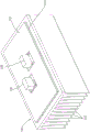
Fig. 8 is an exploded perspective view of the electrical junction box.
Fig. 9 is a perspective view of the electrical junction box.
Fig. 10 is a top view of the electrical junction box.
Fig. 11 is a sectional view a-a of fig. 10.
Fig. 12 is an exploded perspective view of the circuit structure and the heat sink according to embodiment 2.
Fig. 13 is a perspective view of the circuit structure and the heat sink.
Fig. 14 is a perspective view of the circuit structure and the heat sink.
Fig. 15 is a bottom view of a part of the circuit structure.
Fig. 16 is a sectional view B-B of fig. 15.
Fig. 17 is an exploded perspective view of a coil assembly and a heat sink according to embodiment 3.
Fig. 18 is a perspective view of the coil assembly and the heat sink.
Fig. 19 is an exploded perspective view of the circuit structure.
Fig. 20 is a perspective view of the circuit structure.
Detailed Description
< embodiment 1>
Embodiment 1 is described with reference to fig. 1 to 11.
(coil assembly 10)
The coil assembly 10 of the present embodiment is formed by housing the core 12 and the coil 16 wound with a winding in the coil case 20. Hereinafter, the coil assembly 10 will be described with the upper side in fig. 1 being the upper side, the lower side being the lower side, the left inner side being the left, the right front side being the right, and the left front side being the front, and the right inner side being the rear.
The magnetic core 12 has a structure called a PQ core, and is formed by combining a pair of first and second cores 12A and 12B having the same shape. The first core 12A and the second core 12B have: a cylindrical wound portion 13; a pair of substantially plate-shaped leg portions 14 extending in parallel along the axial direction L of the wound portion 13 on both left and right sides across the wound portion 13; and a plate-shaped connecting portion 15 formed by connecting the wound portion 13 and one end portions of the pair of leg portions 14 to each other. The wound portion 13 and the leg portion 14 are at the same height as the connecting portion 15. Of the side edges of the connecting portion 15, a pair of side edges (side edges disposed on the front and rear sides) not connected to the leg portion 14 are cut away so as to be inclined from both end portions of the leg portion 14 toward the wound portion 13.
The coil 16 is an edgewise coil 16 in which a winding is formed of a flat wire and is wound edgewise. As shown in fig. 1, edgewise coil 16 is formed such that both end portions of a rectangular wire extend from a winding portion 17 formed by winding the rectangular wire in a cylindrical shape toward front F (an example of the extending direction in the same direction) at different heights, that is, in parallel to each other in a direction substantially orthogonal to axial direction L of winding portion 17.
The front ends of both end portions of the rectangular wire form a pair of connector connection portions 18A, 18B that are slightly wide and substantially flat. Guide grooves 19 for guiding a fitting posture with which a board-side connector 35 described later is fitted are provided extending in the front-rear direction on the upper surfaces of the connector connection portions 18A, 18B. The connector connection portions 18A and 18B are flat plate-shaped as a whole and can be connected to a board-side connector 35 described later.
The winding portion 17 of the edgewise coil 16 is disposed around the wound portion 13 of the pair of first and second cores 12A and 12B, thereby forming the choke coil 11 together with the core 12.
The choke coil 11 is housed in the coil case 20. The coil case 20 is made of a synthetic resin material, and has a form in which a front surface, a rear surface, an upper surface, and a lower surface are each partially continuously open with respect to the choke coil 11. That is, the coil case 20 is constituted by a pair of divided bodies 20A, 20B, and the pair of divided bodies 20A, 20B sandwich the choke coil 11 with a gap D therebetween from the pair of leg portions 14 side, in other words, from the direction intersecting the axial direction L of the winding portion 17 and the direction intersecting the extending direction (front F) (see fig. 2).
More specifically, the pair of divided bodies 20A and 20B of the coil case 20 are each formed into a substantially U-shape in front view (see fig. 4) in which a side wall 23 covering the entire side surface (the leg portion 14) of the choke coil 11, an upper wall 21 (an example of a wall portion) covering a part of the upper surface of the choke coil 11, and a bottom wall 22 (an example of a wall portion) covering a part of the lower surface of the choke coil 11 are connected to each other. The upper wall 21 and the bottom wall 22 are connected to each other at the rear side by a rear wall 24 (an example of a wall portion) (see fig. 5). The rear wall 24 is also connected to the side wall 23 and is thicker than the other wall portions.
On the inner surface side of the rear wall 24, an accommodation recess 24A is provided, and the accommodation recess 24A is formed in a shape that the rear end portion of the choke coil 11 (the rear end portion of the coupling portion 15 of the core 12 and the winding portion 17 of the coil 16) is fitted just inside in a state where the respective divided bodies 20A and 20B are attached to the choke coil 11 (a state where the choke coil 11 is covered with the coil case 20) (see fig. 1 and 8).
As shown in fig. 8, for example, the peripheral region of the accommodating recess 24A into which the winding portion 17 is fitted is projected in a stepped manner toward the split bodies 20A and 20B on the other side, whereby the winding portion 17 having a curved shape is fitted more deeply into the inside (hereinafter, the portion into which the winding portion 17 is fitted is referred to as a coil fitting portion 29). On the inner peripheral surface of the coil fitting portion 29, a plurality of partition walls 29A fitted between adjacent rectangular wires in the winding portion 17 protrude inward (see fig. 4), and the rectangular wires and the adjacent rectangular wires are held in an insulated state by the partition walls 29A.
A pair of slits 25 extending rearward from the front end edges of the pair of side walls 23 are formed, an elastic piece 26 elastically deformable outward is formed in a region between the slits 25, and a locking claw 26A protruding inward is provided at the front end edge of the elastic piece 26. Thus, the respective divided bodies 20A and 20B are formed such that, in a state of being mounted on the choke coil 11 (a state of the choke coil 11 being covered with the coil case 20), the rear end portion of the choke coil 11 is fitted into the accommodation recess 24A, and the front end edge (the front end edge of the leg portion 14 of the core 12) is locked by the locking claw 26A.
The pair of elastic pieces 26 are set to different heights so as to avoid interference with the pair of connector connection portions 18A, 18B of the coil 16 (see fig. 4).
Plate-shaped fixing pieces 27 are integrally erected outward on the pair of side walls 23 of the coil case 20. The fixing piece 27 is vertically erected from each side wall 23 so that its plate surface faces in the front-rear direction, in other words, in the extending direction (front F) of the connector connecting portions 18A, 18B. The fixing pieces 27 are each formed with a mounting hole 27A for mounting to a coil base 53 (an example of a fixed portion) described later.
(Circuit Structure 30)
For example, as shown in fig. 8, a coil assembly 10 and electronic components are mounted on a predetermined position of a circuit board 31 in which a conductive circuit, not shown, is formed on the front surface of an insulating substrate by a printed wiring technique and a plurality of bus bars 33 are wired/bonded in a predetermined pattern on the rear surface, thereby forming a circuit structure 30. In the present embodiment, only the coil assembly 10 is illustrated, and other electronic components are omitted.
The circuit board 31 has a rectangular shape, and a through hole 32 for connection is provided in a portion where the coil assembly 10 is mounted. The connection terminal 33A is formed by bending the front end side of the bus bar 33 exposed from the connection through hole 32 and connected to the coil assembly 10 in an L shape so as to protrude toward the front surface side of the circuit board 31. A metal relay terminal 34 is attached to the connection terminal 33A.
The relay terminal 34 has a square tubular shape as a whole, and includes an elastic contact piece (not shown) formed by folding back a tongue piece extending from one side wall on the inner side thereof (see fig. 16 of embodiment 2). The relay terminal 34 is electrically connected to the connection terminal 33A by sandwiching the connection terminal 33A between the cylindrical outer wall and the elastic contact piece in a state of being attached to the connection terminal 33A of the busbar 33, and forms a board-side connector 35 (an example of a receiving-side connector) together with the connection terminal 33A.
When the connector connection portions 18A and 18B of the coil assembly 10 are fitted to the board-side connector 35, the guiding ribs (not shown) provided on the elastic contact pieces of the relay terminals 34 are fitted to the guiding grooves 19 of the connector connection portions 18A and 18B, thereby guiding the fitting posture of the coil assembly 10 with respect to the board-side connector 35. In a normal fitting state, the elastic contact pieces are positioned between the connector connection portions 18A and 18B and the connection terminal 33A of the busbar 33 to electrically connect the two. The board-side connector 35 opens upward in fig. 8.
(Heat sink 41)
A heat sink 41 (an example of an outer case and a fixed-side case) is disposed on the lower surface side (bus bar 33 side surface) of the circuit board 31. The heat sink 41 is a heat dissipating member made of a metal material having excellent thermal conductivity, such as aluminum or an aluminum alloy, and has a function of dissipating heat generated in the circuit board 31.
A plurality of plate-like fins 42 extending downward are provided on the lower surface of the heat sink 41. Although not shown, an insulating sheet 48 for insulating the heat sink 41 from the circuit board 31 (bus bars 33) is stacked on the upper surface of the heat sink 41. The insulating sheet 48 has adhesiveness to be fixed to the busbar 33 and the heat sink 41.
(cover 50)
The upper side of the circuit board 31 is covered with a cover 50 (an example of an outer case and a cover-side case). The cover 50 is made of metal, includes a rectangular top plate 51 and 4 side walls 52 extending downward from side edges of the top plate 51, and is formed in a box shape.
A coil holder 53 (an example of a fixed portion) is provided at a predetermined position on the lower surface of the top plate 51 at a position corresponding to the fixing piece 27 of the coil assembly 10 in order to fix the coil assembly 10 to the cover 50 (see fig. 11). The pair of coil holders 53 are formed in a pair of prism shapes as follows: when the coil assembly 10 is disposed at a predetermined position, the height dimension along the outer sides of the pair of side walls 23 of the coil case 20 and overlapping the fixing piece 27 is set. A fixing hole 53A is also provided in the coil seat 53 at a position corresponding to the mounting hole 27A of the fixing piece 27 when the fixing piece 27 of the coil assembly 10 is overlapped.
The coil assembly 10 is integrally fixed to a predetermined position of the cover 50 by overlapping the pair of fixing pieces 27 of the coil assembly 10 with the coil holder 53 and fastening the bolts 55.
Next, a method of manufacturing the coil assembly 10, the circuit structure 30, and the electrical junction box 1 will be described.
To manufacture the coil assembly 10, first, the pair of divided bodies 20A and 20B of the coil case 20 are attached so as to cover the pair of leg portions 14 of the choke coil 11. The pair of segments 20A and 20B are attached to the choke coil 11 with a gap (interval D) therebetween. Accordingly, the choke coil 11 is in a state in which both ends in the left-right direction of the pair of coupling portions 15 and the winding portion 17 are covered with the coil case 20 (divided bodies 20A, 20B) and the central portions of the upper and lower surfaces and the central portions of the front and rear surfaces are continuously opened, and thus, a part of the choke coil 11 (the core 12 and the coil 16) is exposed to the outside. In addition, the open portion in the coil housing 20 constitutes the opening 28. The opening 28 is for heat dissipation.
Next, the cover 50 is turned upside down, and the coil assembly 10 is fitted between the pair of coil holders 53 in such an orientation that the pair of fixing pieces 27 of the coil assembly 10 overlaps the pair of coil holders 53 provided on the cover 50. The coil assembly 10 is mounted at a predetermined position of the cover 50 by aligning the mounting holes 27A of the pair of fixing pieces 27 of the coil assembly 10 with the fixing holes 53A of the coil holder 53 and fastening the coil assembly with the bolts 55. In this state, the pair of connector connection portions 18A, 18B of the coil assembly 10 protrude toward the opposite side of the top plate portion 51 of the cover 50.
Next, the circuit board 31 is mounted on a predetermined position of the heat sink 41, covered from above by the cover 50 to which the coil assembly 10 is fixed, and the cover 50 and the heat sink 41 are fixed to each other by a fixing structure (not shown) (see fig. 9 and 11).
At this time, the pair of connector connection portions 18A, 18B fixed to the cover 50 and projecting downward are fitted into the board-side connector 35 of the circuit board 31 opened upward. In other words, the coil assembly 10 is connected to the board-side connector 35 in such an orientation that the extending direction F of the pair of connector connection portions 18A and 18B intersects the circuit board 31.
Thus, the coil assembly 10 is electrically connected to the conductive circuit of the circuit board 31. Thus, the circuit structure 30 in which the connector connection portions 18A and 18B of the coil assembly 10 are connected to the board-side connector 35 of the circuit board 31 and the electrical junction box 1 in which the circuit structure 30 is accommodated inside the outer case 40 including the heat sink 41 and the cover 50 are completed.
Next, the operation and effect of the present embodiment will be described.
According to the present embodiment, when the coil assembly 10 is conductively connected to the circuit board 31, the connector connection portions 18A and 18B on the coil assembly 10 side may be fitted to the board-side connector 35. That is, since bolt fastening is not required as in the conventional case, a space for bolt fastening is not required on the circuit board 31, and thus the circuit structure 30 and the electrical junction box 1 can be downsized.
Further, since the bolt and the nut are not required, the number of parts can be reduced, and a structure for holding the nut is not required, so that the entire structure can be simplified. Further, since a structure for reliably insulating the heat sink 41 from the nut is not required, the structure can be simplified as compared with the conventional structure.
Further, since the coil case 20 is configured by the pair of divided bodies 20A and 20B and the relatively large opening 28 is provided by providing the space D between the two, the heat generated by the choke coil 11 (the core 12 and the coil 16) can be quickly dissipated from the opening 28. That is, the coil assembly 10, the circuit structure 30, and the electrical junction box 1 having excellent heat dissipation properties can be obtained.
Further, since the cover 50 is made of metal and is in contact with the coil assembly 10, the heat dissipation performance is more excellent than that in the case of using a cover made of synthetic resin, for example.
Further, the coil assembly 10 is configured to be connected to the board-side connector 35 in such an orientation that the pair of connector connection portions 18A and 18B extend in the same direction from the winding portion 17 and the extending direction F thereof is substantially orthogonal to the circuit board 31, and therefore, the space in which the coil assembly 10 is disposed on the circuit board 31 can be further narrowed. In other words, the circuit structure 30 and the electrical junction box 1 can be made smaller. In addition, in such a configuration, since the choke coil 11 is disposed at a position separated from the circuit board 31, the influence of noise on the conductive circuit of the circuit board 31 by the choke coil 11 can be reduced.
Further, since the coil holder 35 is provided on the cover 50 and the fixing piece 27 of the coil assembly 10 is fixed to the coil holder 35, the coil assembly 10 is less likely to be displaced even if it is displaced from the circuit board 31 due to vibration of the vehicle or the like, and the reliability of connection between the coil assembly 10 and the circuit board 31 can be improved.
Further, by fixing the coil assembly 10 to the cover 50 in advance, the electric junction box 1 can be easily manufactured simply by assembling the cover 50 to the heat sink 41.
< embodiment 2>
Next, embodiment 2 will be described with reference to fig. 12 to 16. Hereinafter, only the structure different from embodiment 1 will be described. Note that, for the same configurations as those in embodiment 1, numerals obtained by adding 50 to the numerals assigned to the respective configurations are used, and redundant description is omitted. The description will be given with the upper side of fig. 12 as the upper side and the lower side as the lower side.
The orientation of the fixing piece 77 of the coil assembly 60 of the present embodiment provided to the coil case 70 is different from the coil assembly 10 of embodiment 1. Specifically, the fixing piece 77 is vertically erected from each side wall 73 so that its plate surface faces in the vertical direction, that is, in the direction intersecting the extending direction (front F) of the pair of connector connecting portions 68A, 68B. Further, a reinforcing portion 79 is integrally provided at the rear side edge portion of the pair of fixing pieces 77 so as to stand from the side wall 73 with the plate surface thereof facing the front-rear direction.
In the circuit board 81 of the present embodiment, the bus bars 83 connected to the coil assembly 60 among the plurality of bus bars 83 wired on the back surface extend outward from one side edge portion of the circuit board 81 and are bent upward in a crank shape. The front end side thereof is a connection terminal 83A, and a board-side connector 85 (an example of a receiving-side connector) is formed together with a metal relay terminal 84 attached to the connection terminal 83A. The board-side connector 85 is open in a direction along the board surface of the circuit board 81.
The circuit board 81 of the present embodiment has a size covering approximately half of the upper surface of the heat sink 91.
On the other hand, a heat sink 91 (an example of an outer case and a fixed-side case) is disposed on the lower surface side of the circuit board 81 with an insulating sheet 98 interposed therebetween. A pair of coil holders 93 (an example of a fixed portion) for fixing the coil assembly 60 is integrally provided at predetermined positions on the upper surface (the surface on which the circuit board 81 is disposed) of the heat sink 91. The coil holder 93 has a two-step shape in which the circuit board 81 side is higher, and a fixing hole 93A for fixing the fixing piece 77 is provided in a lower upper surface thereof.
Further, at a position corresponding to the coupling portion 65 of the core 62 exposed from the coil case 70 in a state where the coil assembly 60 is disposed, in the upper surface of the heat sink 91, a contact projection 94 for contacting the core 62 (the coupling portion 65) is provided so as to extend in the front-rear direction and to be inserted between the pair of divided bodies 70A, 70B. The width of the contact projection 94 is set to be substantially equal to the distance D between the pair of divided bodies 70A and 70B.
The coil assembly 60 of the present embodiment is connected to the circuit board 81 as follows.
First, the pair of connector connection portions 68A and 68B of the coil assembly 60 are oriented to face the opening of the board-side connector 85, and the coil assembly 60 is brought closer to the board-side connector 85. At this time, the coil assembly 60 is in a so-called lateral state with respect to the circuit board 81.
Then, the contact projection 94 of the heat sink 91 is relatively inserted between the pair of divided bodies 70A and 70B of the coil assembly 60, whereby the fitting posture of the coil assembly 60 is guided to the standard posture. Further, when the coil assembly 60 is brought close to the board-side connector 85, the pair of connector connection portions 68A and 68B of the coil assembly 60 enter the board-side connector 85 and are fitted, and the fixing piece 77 and the coil holder 93 are overlapped.
At the standard fitting position, the leading edge of the fixing piece 77 abuts against the step portion 93B of the coil holder 93, and the mounting hole 77A of the fixing piece 77 coincides with the fixing hole 93A of the coil holder 93. Then, a bolt, not shown, is passed through and fastened to the nut, thereby fixing the coil assembly 60 at a predetermined position of the heat sink 91. Finally, the cover is covered from above by a case not shown.
Thus, the coil assembly 60 is electrically connected to the conductive circuit of the circuit board 81. Thus, the circuit structure 80 in which the connector connection portions 68A and 68B of the coil assembly 60 are connected to the board-side connector 85 of the circuit board 81 and the electrical junction box in which the circuit structure 80 is mounted on the heat sink 91 and housed in the case are completed.
According to the present embodiment, the coil assembly 60 is configured to be connected to the board-side connector 85 in such an orientation that the extending direction F of the pair of connector connecting portions 68A and 68B is along the orientation of the circuit board 81 and the connecting portion 65 of the core 62 is in contact with the contact convex portion 94, so that heat generated from the coil assembly 60 can be quickly conducted to the heat sink 91. This makes it possible to obtain the circuit structure 80 and the electrical junction box having excellent heat dissipation properties.
< embodiment 3>
Next, embodiment 3 will be described with reference to fig. 17 to 20. Hereinafter, only the structure different from embodiment 1 will be described. Note that, for the same structure as that of embodiment 1, numerals obtained by adding 100 to the numerals assigned to the respective structures are used, and redundant description is omitted. The description will be given with the upper side of fig. 17 as the upper side and the lower side as the lower side.
The coil assembly 110 of the present embodiment is different from the coil assembly 10 of embodiment 1 described above in that no fixing piece is provided on the coil case 120.
Further, although the circuit board 131 of the present embodiment is formed by bending the front end side of the bus bar 133 exposed from the connection through hole 132 and connected to the coil assembly 110 upward in an L shape as the connection terminal 133A, no relay terminal is mounted unlike the above embodiment 1.
On the other hand, a housing recess 143 for housing the coil assembly 110 is provided at a predetermined position of the heat sink 141. The housing recess 143 is formed in a shape in which the coil assembly 110 is fitted inside with the connector connecting portions 118A and 118B projecting outward.
Further, a pair of opening edge portions facing each other of the housing recess 143 is provided with an operation recess 144, and the operation recess 144 is cut out outward and connected to the opening edge portions, and is used for inserting a finger or a machine for taking out and putting in the coil assembly 110.
In the present embodiment, the coil assembly 110 is first accommodated in the accommodating recess 143 of the heat sink 141 in a state where the pair of connector connecting portions 118A and 118B protrude outward (upward) (see fig. 18), and the circuit board 131 is overlapped with the upper surface of the heat sink 141 (see fig. 19). Then, the tip (connection terminal 133A) of the bus bar 133 protruding upward from the connection through hole 132 provided in the circuit board 131 and the connector connection portions 118A and 118B of the coil assembly 110 protruding from the connection through hole 132 are protruded upward from the circuit board 131 in a state where the plate surfaces thereof are opposed to each other in parallel. Therefore, the relay connector 136 having a relay terminal (not shown) for connecting both terminals is fitted and connected to each terminal (133A, 118A, or 118B), whereby the circuit board 131 to which the coil assembly 110 is connected can be obtained.
According to this embodiment, the number of components can be reduced. The heat generated from the coil assembly 110 can be more effectively dissipated by the heat sink 141.
< other embodiment >
The technology disclosed in the present specification is not limited to the embodiments described above and illustrated in the drawings, and for example, the following embodiments are also included in the technical scope.
(1) In the above-described embodiment, the connector connection portion of the coil assembly is configured to be connected to the board-side connector on the circuit board, but the counterpart-side connector (the receptacle-side connector) is not limited to the above-described embodiment. For example, the connector may be configured to be connected to a connector provided outside the electrical junction box.
(2) In the above embodiment, the coil case is configured to have a relatively large opening formed by the pair of divided bodies, but the coil case is not limited to the above embodiment, and may be configured to have a relatively small opening on a side surface of a box-shaped coil case having one surface as an insertion opening for inserting the coil. Alternatively, the opening for heat dissipation may not be provided.
(3) In the above embodiment, both the core 12 and the coil 16 are configured to be exposed to the outside from the opening 28 of the coil case 20, but either one may be configured to be exposed.
(4) In the above embodiment, the coil case is configured to be provided with the fixing piece for fixing the coil assembly to the fixed portion, but the fixing piece may be omitted.
(5) In the above embodiment, the coil holder is provided in the outer case as an example of the fixed portion for fixing the coil assembly, but the fixed portion is not limited to the above embodiment. For example, the outer case may be provided with a fitting recess into which the coil assembly is fitted.
(6) In the above embodiment, the coil assembly is configured to be connected to the connector provided on the circuit board, but the coil assembly may be connected to a connector other than the connector provided on the circuit board.
(7) In embodiment 1 described above, the cover 50 is made of metal, but may be made of synthetic resin.
(8) In the above embodiment, the connector connection portions 18A and 18B configured as the coil 16 include the guide groove 19, but a flat plate-shaped connector connection portion not including the guide groove 19 is also included in the technical scope of the present invention.
Description of the reference symbols
1: electrical junction box
10. 60, 110: coil assembly
12. 62, 112: magnetic core
13: wound part
15. 65: connecting part
16. 66, 116: coil
17: winding part
18A, 18B, 68A, 68B, 118A, 118B: connector connecting part
20. 70, 120: coil shell
20A, 20B, 70A, 70B, 120A, 120B: partition body
21: upper wall (wall part)
22: bottom wall (wall part)
23: side wall
24: rear wall (wall part)
27. 77: fixing sheet
28. 78, 128: opening of the container
30. 80, 130: circuit structure
31. 81 and 181: circuit board
33. 83, 133: bus bar
33A, 83A, 133A: connecting terminal
34. 84: shell body
35. 85: substrate side connector (receiving side connector)
40. 90: outer casing
41. 91, 141: heat sink (fixed side shell, heat radiation component)
50: cover (side cover shell)
53. 93: coil holder (fixed part)
143: accommodating recess
136: relay connector (receiving side connector)
D: interval (gap)
F: front (extending direction)
L: axial direction
Claims (13)
1. A coil assembly comprising a core and a coil having a winding portion formed by winding a flat wire in a flat state,
both end portions of the flat wire extend in the same direction from the winding portion, and constitute a connector connection portion to which a receiving-side connector is connected,
the magnetic core and the coil are housed in a coil case, an opening for heat dissipation is provided in at least a wall portion of the coil case that intersects with the axial direction of the winding portion, and at least a portion of the magnetic core is exposed from the opening.
2. The coil assembly of claim 1,
the coil case is composed of a pair of divided bodies that sandwich the core and the coil with a gap therebetween from a direction intersecting the axial direction.
3. The coil assembly according to claim 1 or 2, wherein,
the coil case is integrally provided with a fixing piece for fixing the coil case to a fixed portion.
4. The coil assembly according to claim 1 or 2, wherein,
the connector connecting portion is flat plate-shaped.
5. A circuit structure, wherein the coil assembly according to any one of claims 1 to 4 is electrically connected to a circuit board provided with the receiving-side connector.
6. A circuit structure, wherein the coil assembly according to any one of claims 1 to 4 is conductively connected to a circuit board via the receiving-side connector, and the receiving-side connector is provided separately from the circuit board and is conductively connectable to the circuit board.
7. The circuit structure body according to claim 5 or 6,
the coil assembly is connected to the receiving-side connector in an orientation in which an extending direction of the connector connecting portion extending from the winding portion intersects with the circuit board.
8. The circuit structure body according to claim 5 or 6,
the coil assembly is connected to the receiving-side connector in an orientation in which an extending direction of the connector connecting portion from the winding portion is along an orientation of the circuit board.
9. An electrical junction box comprising the circuit structure according to any one of claims 5 to 8 housed in an outer case.
10. The electrical connection box of claim 9,
the outer case is provided with a fixed portion for fixing the coil assembly.
11. The electrical connection box of claim 10,
the outer case includes a fixed-side case that fixes the circuit board and a cover-side case that covers the circuit board fixed to the fixed-side case,
the fixed part is provided to the cover-side housing.
12. The electrical connection box of claim 11,
the shell side housing is made of metal.
13. The electrical junction box of any one of claims 9 to 12,
the outer case includes a heat dissipating member in thermal conductive contact with the circuit board, and the heat dissipating member is provided with a receiving recess for receiving the coil assembly in thermal conductive contact.
Applications Claiming Priority (3)
| Application Number | Priority Date | Filing Date | Title |
|---|---|---|---|
| JP2016162042A JP6551338B2 (en) | 2016-08-22 | 2016-08-22 | Coil assembly, circuit assembly, and electrical connection box |
| JP2016-162042 | 2016-08-22 | ||
| PCT/JP2017/029599 WO2018038008A1 (en) | 2016-08-22 | 2017-08-18 | Coil assembly, circuit component, and junction box |
Publications (2)
| Publication Number | Publication Date |
|---|---|
| CN109564812A CN109564812A (en) | 2019-04-02 |
| CN109564812B true CN109564812B (en) | 2021-03-09 |
Family
ID=61246535
Family Applications (1)
| Application Number | Title | Priority Date | Filing Date |
|---|---|---|---|
| CN201780050124.2A Active CN109564812B (en) | 2016-08-22 | 2017-08-18 | Coil assembly, circuit structure, and electrical junction box |
Country Status (5)
| Country | Link |
|---|---|
| US (1) | US20210287843A1 (en) |
| JP (1) | JP6551338B2 (en) |
| CN (1) | CN109564812B (en) |
| DE (1) | DE112017004172T5 (en) |
| WO (1) | WO2018038008A1 (en) |
Families Citing this family (2)
| Publication number | Priority date | Publication date | Assignee | Title |
|---|---|---|---|---|
| JP7116612B2 (en) * | 2018-07-17 | 2022-08-10 | ダイヤゼブラ電機株式会社 | TERMINAL UNIT, COIL COMPONENT INCLUDING THE SAME, AND COIL COMPONENT MANUFACTURING METHOD |
| JP7298545B2 (en) * | 2020-05-27 | 2023-06-27 | 株式会社村田製作所 | Coil parts and electronic parts |
Citations (6)
| Publication number | Priority date | Publication date | Assignee | Title |
|---|---|---|---|---|
| JP2001297924A (en) * | 2000-04-17 | 2001-10-26 | Cosel Co Ltd | Transformer |
| CN1961389A (en) * | 2004-06-04 | 2007-05-09 | 胜美达集团株式会社 | Inductor |
| KR20140032095A (en) * | 2012-09-05 | 2014-03-14 | 엘에스산전 주식회사 | Magnetic element |
| JP2015185725A (en) * | 2014-03-25 | 2015-10-22 | Fdk株式会社 | Transformer |
| WO2016002326A1 (en) * | 2014-07-04 | 2016-01-07 | 株式会社オートネットワーク技術研究所 | Coil assembly, mounting structure for coil assembly, and electrical connection box |
| JP2016127121A (en) * | 2014-12-26 | 2016-07-11 | 株式会社エス・エッチ・ティ | Common mode choke coil |
Family Cites Families (11)
| Publication number | Priority date | Publication date | Assignee | Title |
|---|---|---|---|---|
| JPS4920281Y1 (en) * | 1970-10-02 | 1974-05-30 | ||
| JPH0513016U (en) * | 1991-07-30 | 1993-02-19 | 東邦亜鉛株式会社 | Inductor |
| JP3573603B2 (en) * | 1997-08-29 | 2004-10-06 | 松下電工株式会社 | Electromagnetic device |
| JP2006303391A (en) * | 2005-04-25 | 2006-11-02 | Sagami Ereku Kk | Coil for digital amplifier |
| JP2009126286A (en) * | 2007-11-21 | 2009-06-11 | Autonetworks Technologies Ltd | On-vehicle junction box |
| JP5213679B2 (en) * | 2008-12-15 | 2013-06-19 | 東京特殊電線株式会社 | Coil device |
| JP5488328B2 (en) * | 2010-08-17 | 2014-05-14 | パナソニック株式会社 | Electronic component and manufacturing method thereof |
| CN103700471B (en) * | 2013-11-19 | 2017-02-15 | 淮安市鼎新电子有限公司 | Adjustable transformer |
| JP2015104183A (en) | 2013-11-22 | 2015-06-04 | 株式会社オートネットワーク技術研究所 | Circuit structure body and dc-dc converter device |
| JP6175609B2 (en) * | 2015-02-04 | 2017-08-09 | ダイキン工業株式会社 | Reactor-equipped device and reactor |
| CN205230782U (en) * | 2015-12-24 | 2016-05-11 | 重庆益堡科技有限公司 | Inductor of practicality and anti -electromagnetic interference ability reinforce |
-
2016
- 2016-08-22 JP JP2016162042A patent/JP6551338B2/en active Active
-
2017
- 2017-08-18 CN CN201780050124.2A patent/CN109564812B/en active Active
- 2017-08-18 WO PCT/JP2017/029599 patent/WO2018038008A1/en active Application Filing
- 2017-08-18 US US16/326,416 patent/US20210287843A1/en not_active Abandoned
- 2017-08-18 DE DE112017004172.4T patent/DE112017004172T5/en active Pending
Patent Citations (6)
| Publication number | Priority date | Publication date | Assignee | Title |
|---|---|---|---|---|
| JP2001297924A (en) * | 2000-04-17 | 2001-10-26 | Cosel Co Ltd | Transformer |
| CN1961389A (en) * | 2004-06-04 | 2007-05-09 | 胜美达集团株式会社 | Inductor |
| KR20140032095A (en) * | 2012-09-05 | 2014-03-14 | 엘에스산전 주식회사 | Magnetic element |
| JP2015185725A (en) * | 2014-03-25 | 2015-10-22 | Fdk株式会社 | Transformer |
| WO2016002326A1 (en) * | 2014-07-04 | 2016-01-07 | 株式会社オートネットワーク技術研究所 | Coil assembly, mounting structure for coil assembly, and electrical connection box |
| JP2016127121A (en) * | 2014-12-26 | 2016-07-11 | 株式会社エス・エッチ・ティ | Common mode choke coil |
Also Published As
| Publication number | Publication date |
|---|---|
| DE112017004172T5 (en) | 2019-05-02 |
| CN109564812A (en) | 2019-04-02 |
| US20210287843A1 (en) | 2021-09-16 |
| JP6551338B2 (en) | 2019-07-31 |
| JP2018032665A (en) | 2018-03-01 |
| WO2018038008A1 (en) | 2018-03-01 |
Similar Documents
| Publication | Publication Date | Title |
|---|---|---|
| US20100055962A1 (en) | Electric connection box | |
| JP5997279B2 (en) | Connection structure between electronic component assembly and terminal fitting, electric junction box having electronic component assembly | |
| US9179560B2 (en) | Board block for vehicles | |
| JP4055662B2 (en) | Electrical junction box | |
| JP5223591B2 (en) | Electrical junction box | |
| US20190229509A1 (en) | Connection Structure of Electrical Junction Box and Protection Member | |
| CN109564812B (en) | Coil assembly, circuit structure, and electrical junction box | |
| JP5108402B2 (en) | Electrical junction box | |
| JP2006109587A (en) | Connection structure for wire and element-incorporated unit | |
| JP7346844B2 (en) | electronic module | |
| JP7264655B2 (en) | electric junction box | |
| JP3395638B2 (en) | Electrical junction box | |
| EP1577977A1 (en) | Electrical junction box | |
| JP4851170B2 (en) | Board with connector | |
| JP7280230B2 (en) | electric junction box | |
| JP2019153572A (en) | Bus bar holding structure, electric connection box, and wire harness | |
| JP6835795B2 (en) | Busbar retainer structure, electrical junction box, and wire harness | |
| JP2003032840A (en) | Electrical connection box | |
| JP7234847B2 (en) | electronic module | |
| JP3915447B2 (en) | Junction block | |
| JP7154975B2 (en) | electric junction box | |
| JP2011182611A (en) | Printed board with connection terminal | |
| WO2020153143A1 (en) | Circuit structure and electrical junction box | |
| JP7107659B2 (en) | electric junction box | |
| JP2000083313A (en) | Electrical junction box |
Legal Events
| Date | Code | Title | Description |
|---|---|---|---|
| PB01 | Publication | ||
| PB01 | Publication | ||
| SE01 | Entry into force of request for substantive examination | ||
| SE01 | Entry into force of request for substantive examination | ||
| GR01 | Patent grant | ||
| GR01 | Patent grant |