CN109496380B - Inductive power transmitter - Google Patents
Inductive power transmitter Download PDFInfo
- Publication number
- CN109496380B CN109496380B CN201780022132.6A CN201780022132A CN109496380B CN 109496380 B CN109496380 B CN 109496380B CN 201780022132 A CN201780022132 A CN 201780022132A CN 109496380 B CN109496380 B CN 109496380B
- Authority
- CN
- China
- Prior art keywords
- frequency
- coil
- inductive power
- response
- transmitter
- Prior art date
- Legal status (The legal status is an assumption and is not a legal conclusion. Google has not performed a legal analysis and makes no representation as to the accuracy of the status listed.)
- Active
Links
- 230000001939 inductive effect Effects 0.000 title claims abstract description 83
- 238000001514 detection method Methods 0.000 claims abstract description 139
- 230000004044 response Effects 0.000 claims abstract description 63
- 238000012546 transfer Methods 0.000 claims abstract description 29
- 238000000034 method Methods 0.000 claims description 35
- 230000005540 biological transmission Effects 0.000 claims description 24
- 239000003990 capacitor Substances 0.000 claims description 5
- 230000010363 phase shift Effects 0.000 claims description 2
- 230000005284 excitation Effects 0.000 description 60
- 229910000859 α-Fe Inorganic materials 0.000 description 30
- 230000008859 change Effects 0.000 description 20
- 238000010586 diagram Methods 0.000 description 17
- 230000004907 flux Effects 0.000 description 17
- 238000005259 measurement Methods 0.000 description 16
- 238000004891 communication Methods 0.000 description 11
- 238000004422 calculation algorithm Methods 0.000 description 10
- 230000006870 function Effects 0.000 description 10
- 238000004804 winding Methods 0.000 description 10
- 239000004020 conductor Substances 0.000 description 8
- 230000008878 coupling Effects 0.000 description 7
- 238000010168 coupling process Methods 0.000 description 7
- 238000005859 coupling reaction Methods 0.000 description 7
- 230000000694 effects Effects 0.000 description 6
- 239000002184 metal Substances 0.000 description 6
- 229910052751 metal Inorganic materials 0.000 description 6
- 230000035945 sensitivity Effects 0.000 description 6
- 238000013459 approach Methods 0.000 description 4
- 230000003750 conditioning effect Effects 0.000 description 4
- 230000009977 dual effect Effects 0.000 description 4
- 230000001965 increasing effect Effects 0.000 description 4
- 238000004519 manufacturing process Methods 0.000 description 4
- 230000008901 benefit Effects 0.000 description 3
- 238000004364 calculation method Methods 0.000 description 3
- 238000002474 experimental method Methods 0.000 description 3
- 230000003071 parasitic effect Effects 0.000 description 3
- 230000008569 process Effects 0.000 description 3
- 230000002441 reversible effect Effects 0.000 description 3
- 239000004065 semiconductor Substances 0.000 description 3
- 230000003595 spectral effect Effects 0.000 description 3
- XUIMIQQOPSSXEZ-UHFFFAOYSA-N Silicon Chemical compound [Si] XUIMIQQOPSSXEZ-UHFFFAOYSA-N 0.000 description 2
- 238000003491 array Methods 0.000 description 2
- 230000006399 behavior Effects 0.000 description 2
- 239000000969 carrier Substances 0.000 description 2
- 230000001419 dependent effect Effects 0.000 description 2
- 238000005516 engineering process Methods 0.000 description 2
- 238000010438 heat treatment Methods 0.000 description 2
- 230000001976 improved effect Effects 0.000 description 2
- 230000000977 initiatory effect Effects 0.000 description 2
- 150000002739 metals Chemical class 0.000 description 2
- 230000002829 reductive effect Effects 0.000 description 2
- 229910052710 silicon Inorganic materials 0.000 description 2
- 239000010703 silicon Substances 0.000 description 2
- 238000004088 simulation Methods 0.000 description 2
- 206010000117 Abnormal behaviour Diseases 0.000 description 1
- CWYNVVGOOAEACU-UHFFFAOYSA-N Fe2+ Chemical compound [Fe+2] CWYNVVGOOAEACU-UHFFFAOYSA-N 0.000 description 1
- 230000004913 activation Effects 0.000 description 1
- 230000006978 adaptation Effects 0.000 description 1
- 230000002547 anomalous effect Effects 0.000 description 1
- 230000033228 biological regulation Effects 0.000 description 1
- 239000002131 composite material Substances 0.000 description 1
- 239000012141 concentrate Substances 0.000 description 1
- MPTQRFCYZCXJFQ-UHFFFAOYSA-L copper(II) chloride dihydrate Chemical compound O.O.[Cl-].[Cl-].[Cu+2] MPTQRFCYZCXJFQ-UHFFFAOYSA-L 0.000 description 1
- 239000013078 crystal Substances 0.000 description 1
- 230000003247 decreasing effect Effects 0.000 description 1
- 238000009826 distribution Methods 0.000 description 1
- 230000002708 enhancing effect Effects 0.000 description 1
- 230000007613 environmental effect Effects 0.000 description 1
- 238000011156 evaluation Methods 0.000 description 1
- 239000000284 extract Substances 0.000 description 1
- 238000007689 inspection Methods 0.000 description 1
- 238000002623 insulin potentiation therapy Methods 0.000 description 1
- 230000002427 irreversible effect Effects 0.000 description 1
- 238000002955 isolation Methods 0.000 description 1
- 230000000670 limiting effect Effects 0.000 description 1
- 239000000696 magnetic material Substances 0.000 description 1
- 239000000463 material Substances 0.000 description 1
- 230000007246 mechanism Effects 0.000 description 1
- 239000007769 metal material Substances 0.000 description 1
- 238000012986 modification Methods 0.000 description 1
- 230000004048 modification Effects 0.000 description 1
- 238000012545 processing Methods 0.000 description 1
- 230000001681 protective effect Effects 0.000 description 1
- 239000010453 quartz Substances 0.000 description 1
- 230000000630 rising effect Effects 0.000 description 1
- 238000005070 sampling Methods 0.000 description 1
- 239000004576 sand Substances 0.000 description 1
- 230000011664 signaling Effects 0.000 description 1
- VYPSYNLAJGMNEJ-UHFFFAOYSA-N silicon dioxide Inorganic materials O=[Si]=O VYPSYNLAJGMNEJ-UHFFFAOYSA-N 0.000 description 1
- 238000003860 storage Methods 0.000 description 1
- 239000000758 substrate Substances 0.000 description 1
- 230000001629 suppression Effects 0.000 description 1
- 238000012549 training Methods 0.000 description 1
- 238000012795 verification Methods 0.000 description 1
Images


Classifications
-
- H—ELECTRICITY
- H04—ELECTRIC COMMUNICATION TECHNIQUE
- H04B—TRANSMISSION
- H04B5/00—Near-field transmission systems, e.g. inductive or capacitive transmission systems
- H04B5/70—Near-field transmission systems, e.g. inductive or capacitive transmission systems specially adapted for specific purposes
- H04B5/79—Near-field transmission systems, e.g. inductive or capacitive transmission systems specially adapted for specific purposes for data transfer in combination with power transfer
-
- H—ELECTRICITY
- H02—GENERATION; CONVERSION OR DISTRIBUTION OF ELECTRIC POWER
- H02J—CIRCUIT ARRANGEMENTS OR SYSTEMS FOR SUPPLYING OR DISTRIBUTING ELECTRIC POWER; SYSTEMS FOR STORING ELECTRIC ENERGY
- H02J50/00—Circuit arrangements or systems for wireless supply or distribution of electric power
- H02J50/10—Circuit arrangements or systems for wireless supply or distribution of electric power using inductive coupling
-
- H—ELECTRICITY
- H02—GENERATION; CONVERSION OR DISTRIBUTION OF ELECTRIC POWER
- H02J—CIRCUIT ARRANGEMENTS OR SYSTEMS FOR SUPPLYING OR DISTRIBUTING ELECTRIC POWER; SYSTEMS FOR STORING ELECTRIC ENERGY
- H02J50/00—Circuit arrangements or systems for wireless supply or distribution of electric power
- H02J50/60—Circuit arrangements or systems for wireless supply or distribution of electric power responsive to the presence of foreign objects, e.g. detection of living beings
-
- H—ELECTRICITY
- H02—GENERATION; CONVERSION OR DISTRIBUTION OF ELECTRIC POWER
- H02J—CIRCUIT ARRANGEMENTS OR SYSTEMS FOR SUPPLYING OR DISTRIBUTING ELECTRIC POWER; SYSTEMS FOR STORING ELECTRIC ENERGY
- H02J50/00—Circuit arrangements or systems for wireless supply or distribution of electric power
- H02J50/80—Circuit arrangements or systems for wireless supply or distribution of electric power involving the exchange of data, concerning supply or distribution of electric power, between transmitting devices and receiving devices
-
- H—ELECTRICITY
- H04—ELECTRIC COMMUNICATION TECHNIQUE
- H04B—TRANSMISSION
- H04B1/00—Details of transmission systems, not covered by a single one of groups H04B3/00 - H04B13/00; Details of transmission systems not characterised by the medium used for transmission
- H04B1/02—Transmitters
- H04B1/04—Circuits
-
- H—ELECTRICITY
- H04—ELECTRIC COMMUNICATION TECHNIQUE
- H04B—TRANSMISSION
- H04B5/00—Near-field transmission systems, e.g. inductive or capacitive transmission systems
- H04B5/20—Near-field transmission systems, e.g. inductive or capacitive transmission systems characterised by the transmission technique; characterised by the transmission medium
- H04B5/24—Inductive coupling
- H04B5/26—Inductive coupling using coils
-
- H—ELECTRICITY
- H04—ELECTRIC COMMUNICATION TECHNIQUE
- H04L—TRANSMISSION OF DIGITAL INFORMATION, e.g. TELEGRAPHIC COMMUNICATION
- H04L27/00—Modulated-carrier systems
- H04L27/10—Frequency-modulated carrier systems, i.e. using frequency-shift keying
- H04L27/12—Modulator circuits; Transmitter circuits
Landscapes
- Engineering & Computer Science (AREA)
- Computer Networks & Wireless Communication (AREA)
- Signal Processing (AREA)
- Power Engineering (AREA)
- Near-Field Transmission Systems (AREA)
- Geophysics And Detection Of Objects (AREA)
- Charge And Discharge Circuits For Batteries Or The Like (AREA)
Abstract
The present invention provides an inductive power transmitter comprising a transmit circuit having a coil, the transmit circuit tuned, adapted or optimized to be at or about a first frequency for inductive power transfer or object detection; an inverter operable to drive the transmit circuit at the first frequency; and a controller arranged to control the inverter to drive the transmit circuit at a second higher frequency and to modulate signals at the second higher frequency in accordance with predetermined handshake signals to generate a response from a predetermined unauthorized device in the vicinity of the coil.
Description
Technical Field
The present invention relates generally to inductive power transmitters, particularly but not exclusively for inductive power transfer systems.
Background
IPT systems are well known areas of prior art (e.g. wireless charging of electric toothbrushes) and developing technology (e.g. wireless charging of handheld devices on "charging pads"). Typically, a power transmitter generates a time-varying magnetic field from one or more transmit coils. This magnetic field induces an alternating current in a suitable receiving coil in the power receiver, which can then be used to charge a battery or power a device or other load.
For IPT systems for wireless charging of handheld devices, it is particularly important that wireless power is only transferred to the receiver device rather than a so-called foreign object, which may be defined as any object positioned on a charging pad (e.g. an interface surface) but not part of the receiver device. Typical examples of such foreign objects are parasitic elements containing metal, such as coins, keys, paperclips, etc. For example, if the parasitic metal is close to the active IPT region, it may heat up during power transfer due to eddy currents generated by the oscillating magnetic field. To prevent the temperature of such parasitic metals from rising to unacceptable levels, the power transmitter should be able to distinguish between the power receiver and the foreign object and suspend power transfer in a timely manner.
Conventional approaches to detecting heating of foreign objects on interface surfaces use power loss methods. In the method, the received power PPR is used to indicate the total amount of power dissipated within a power receiver housed in the handheld device due to a magnetic field generated by the power transmitter. The received power is equal to the power available from the output of the power receiver plus any power lost in generating the output power. The power receiver sends its PPR to the power transmitter so that the power transmitter can determine whether the power loss is within acceptable set limits, and if not, the power transmitter determines abnormal behavior that can indicate the presence of a foreign object and discontinue power transmission. However, this power loss accounting method does not provide actual detection of foreign objects by itself, but only the occurrence of unexpected behavior.
In contrast, international patent publication No. WO2014/095722 proposes a foreign object detection method using an excitation coil and a detection coil within the transmitter separate from the one or more primary IPT transmitter coils. In this case, a change in the output voltage in the detection winding or a change in the inductance of the detection winding is used to determine the possible presence of the object. However, this system requires complex calibration to determine the base inductance. The system is also insensitive to metallic objects relative to ferrous or magnetic objects and therefore does not provide a means to distinguish between foreign objects and friendly objects (e.g. receiver devices). Any undesired effects of the operation of the primary IPT field on the detection are also not considered or characterized, so that the proposed method may be unreliable.
Disclosure of Invention
It is an object of the present invention to provide an improved inductive power transmitter or to provide the public with a useful choice.
According to an exemplary embodiment, an inductive power transmitter is provided, the inductive power transmitter comprising:
a transmit circuit having a coil, the transmit circuit tuned, adapted or optimized to be at or about a first frequency for inductive power transfer or object detection;
an inverter operable to drive the transmit circuit at a first frequency; and
a controller arranged to control the inverter to drive the transmit circuit at a second higher frequency and to modulate a signal at the second higher frequency in accordance with a predetermined handshake signal to generate a response from a predetermined unauthorized device in the vicinity of the coil.
According to a second exemplary embodiment, an inductive power transmitter is provided, the inductive power transmitter comprising:
a transmit circuit having a coil;
an inverter operable to drive the transmit circuit; and
a controller arranged to control the inverter to drive the transmit circuit at a first handshake frequency and to modulate a signal at the first handshake frequency in accordance with a predetermined handshake signal to generate a response from a predetermined unauthorized device in the vicinity of the coil,
wherein the predetermined unauthorized device has a prescribed handshake signal having a carrier frequency higher than the first handshake frequency, and
wherein the predetermined handshake signals comprise a series of consecutive polling commands and the prescribed handshake signals comprise a series of consecutive polling commands, and the number of cycles of each predetermined handshake signal polling command is the same as the number of cycles of each respective prescribed handshake signal polling command.
According to a third exemplary embodiment, an inductive power receiver is provided, comprising:
a receiver circuit having a coil;
an unauthorized resonant device; and
a controller arranged to detect in the coil emission by the inductive power transmitter
A disable signal to disable an unauthorized resonant device based on the disable signal,
and modulates a signal in the coil to instruct the transmitter to begin power transfer.
According to a fourth exemplary embodiment, an inductive power transmitter is provided, the inductive power transmitter comprising:
a transmitter circuit having a coil;
an inverter operable to drive the transmit circuit; and
a controller arranged to control the inverter to drive the transmit circuit at a first ping frequency and to modulate a signal at the first ping frequency in accordance with a disable signal to disable an unauthorized resonant device in an authorized receiver and to detect an activation signal in the coil to initiate power transfer to the authorized receiver.
According to a fifth exemplary embodiment, an inductive power transmitter is provided, the inductive power transmitter comprising:
at least one multi-purpose coil; and
an object detection system configured to detect an object in or near an IPT field;
wherein the object detection system excites the multi-purpose coil to transmit a handshake signal configured to generate a response from a predetermined unauthorized object, and the object detection system detects the unauthorized object based on receiving a valid response.
According to a sixth exemplary embodiment, there is provided an object detection system for an inductive power transmitter, the object detection system comprising:
a memory arranged to store a predetermined signature associated with an authorized inductive power receiver and/or an unauthorized object;
the object detection system is arranged to indicate an unauthorized object in response to:
detecting one or more predetermined signatures of the predetermined signatures associated with unauthorized objects;
and/or detecting a signature that does not correspond to a predetermined signature associated with an authorized receiver.
According to a seventh exemplary embodiment, an inductive power transmitter is provided, the inductive power transmitter comprising:
at least one power transmitting coil configured to generate an Inductive Power Transfer (IPT) field; and is
An object detection system configured to detect an object in or near an IPT field;
wherein the object detection system is configured to detect an unapproved resonant device.
According to an eighth exemplary embodiment, there is provided an object detection system for an inductive power transmitter, the object detection system comprising:
a coil and circuitry arranged to determine reflected impedance at a plurality of frequencies;
a memory arranged to store predetermined frequencies associated with authorised inductive power receivers and/or predetermined frequencies associated with unauthorised receivers; and is
The object detection system is arranged to indicate an unauthorized receiver in response to:
detecting a predetermined increase or decrease in reflected impedance at a predetermined frequency associated with an unauthorized receiver;
and/or detecting a predetermined increase in reflected impedance at frequencies not associated with an authorized inductive power receiver.
According to a ninth exemplary embodiment, there is provided a method of operating an object detection system for an inductive power transmitter, the object detection system comprising a coil and circuitry, the method comprising:
driving the coil at a first power level and determining a first reflected impedance;
driving the coil at a second higher power level and determining a second reflected impedance;
wherein the second power level is sufficient to initiate operation of the predetermined unauthorized receiver instead of the first power level;
an unauthorized receiver is detected in response to determining a predetermined difference between the first reflected impedance and the second reflected impedance.
According to a tenth exemplary embodiment, there is provided a method of operating an object detection system for an inductive power transmitter, the method comprising:
determining reflected impedance at a plurality of frequencies;
indicating an unauthorized receiver in response to:
detecting a predetermined increase or decrease in reflected impedance at a predetermined frequency associated with an unauthorized receiver;
and/or detecting a predetermined increase in reflected impedance at frequencies not associated with an authorized inductive power receiver.
According to an eleventh exemplary embodiment, there is provided an inductive power transmitter comprising:
a transmit circuit having a coil, the transmit circuit tuned to a first frequency for inductive power transfer or object detection;
an inverter operable to drive the transmit circuit at a first frequency;
a controller arranged to control the inverter to drive the transmit circuit at a second higher frequency and to modulate the second higher frequency in accordance with a predetermined handshake signal to generate a response from a predetermined unauthorized device in the vicinity of the coil.
According to a twelfth exemplary embodiment, there is provided a method of operating an inductive power transmitter, the inductive power transmitter comprising: a transmit circuit including a coil and tuned to a first frequency, and an inverter operable to drive the transmit circuit at the first frequency; the method comprises the following steps:
driving the transmit circuit at a second higher frequency to detect any predetermined unauthorized devices in the vicinity of the coil;
modulating the second higher frequency according to a predetermined handshake signal recognizable by an unauthorized device; and
indicating the presence of the unauthorized device in response to detecting a predetermined response.
According to a thirteenth exemplary embodiment, there is provided an inductive power transmitter comprising:
a transmit circuit having a coil;
an inverter operable to drive the transmit circuit;
a controller arranged to control the inverter to drive the transmit circuit at a first handshake frequency and to modulate a signal at the first handshake frequency in accordance with a predetermined handshake signal to generate a response from a predetermined unauthorized device in the vicinity of the coil,
wherein the predetermined unauthorized device has a prescribed handshake signal having a carrier frequency higher than the first handshake frequency, and
wherein the predetermined handshake signals comprise a series of successive modulation states and the prescribed handshake signals comprise a series of successive modulation states, and the number of cycles of the series of modulation states of each predetermined handshake signal is the same as the number of cycles of the series of modulation states of each respective prescribed handshake signal.
It is acknowledged that the terms 'comprise', may, under varying jurisdictions, be attributed with either an exclusive or an inclusive meaning. For the purposes of this specification and unless otherwise indicated, these terms are intended to have an inclusive meaning-i.e., they will be taken to include the listed components, to which use directly refers, and may also include other unspecified components or elements.
The reference to any document in this specification does not constitute an admission that it is prior art or forms part of the common general knowledge.
Drawings
The accompanying drawings, which are incorporated in and constitute a part of the specification, illustrate embodiments of the invention and, together with a general description of the invention given above, and the detailed description of the embodiments given below, serve to explain the principles of the invention.
FIG. 1 is a schematic diagram of an inductive power transfer system;
FIG. 2 is a block diagram of an object detection system;
FIG. 3 is a schematic diagram of a dual OD coil;
FIG. 4 is a schematic diagram of a single OD coil;
FIG. 5 is a schematic diagram of another dual OD coil;
FIG. 6 is a schematic diagram of a transmit coil layout;
FIG. 7 is a schematic diagram showing the interleaved OD and IPT coils around a ferrite;
FIG. 8 is a cross section of a PCB-based OD coil;
FIG. 9 is a simulation of flux lines generated by an excitation coil using IPT ferrite;
FIG. 10A is a flow chart of a detection algorithm;
FIG. 10B is a flow chart of another detection algorithm;
fig. 11 is a schematic diagram of a field coil driver;
fig. 12 is a circuit diagram of the field coil driver;
FIG. 13 is a schematic view of a detector;
FIG. 14 is a circuit diagram of a multiplexer;
FIG. 15 is a circuit diagram of a mixer;
FIG. 16 is a schematic illustration of another embodiment;
FIG. 17 is an impedance plot of various resonant devices;
FIGS. 18A and 18B are actual power diagrams of various resonating devices;
FIG. 19a is a flow chart of a signature method of detecting an unauthorized resonant device such as an RFID/NFC tag;
FIG. 19b is a diagram of polling commands at different carrier frequencies;
FIG. 20 is a circuit diagram of a transmitter with a poll request at 1 MHz;
FIG. 21 is a flow chart of a method of transmitting a polling command to detect an unauthorized resonant device, such as an RFID/NFC tag;
FIG. 22 is a circuit diagram of a transmitter with a poll request at 13.56 MHz;
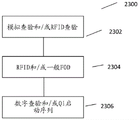
fig. 23 is a flow chart of a method of sending a signal from a transmitter to disable NFC emulation in an active receiver; and is
Fig. 24 is a flow chart of a method of receiving a signal from a transmitter to disable NFC emulation in an active receiver;
Detailed Description
An Inductive Power Transfer (IPT) system 1 is shown generally in figure 1. The IPT system comprises an inductive power transmitter 2 and an inductive power receiver 3. The inductive power transmitter 2 is connected to a suitable power source 4 (such as mains power or a battery). The inductive power transmitter 2 may include a transmitter circuit having one or more of a converter 5 (e.g., an AC-DC converter), depending on the type of power source used, and an inverter 6 (e.g., connected to the converter 5 (if present)). The inverter 6 provides an AC signal to the one or more transmit coils 7 such that the one or more transmit coils 7 generate an alternating magnetic field. In some configurations, one or more transmit coils 7 may also be considered separate from the inverter 5. One or more transmitting coils 7 may be connected in parallel or in series to a capacitor (not shown) to form a resonant circuit.
The controller 8 may be connected to various parts of the inductive power transmitter 2. The controller 8 receives inputs from various parts of the inductive power transmitter 2 and produces outputs that control the operation of the various parts. The controller 8 may be implemented as a single unit or as separate units configured to control various aspects thereof in accordance with the functionality of the inductive power transmitter 2, including for example: power flow, tuning, selective excitation of the transmit coil, inductive power receiver detection and/or communication. The controller 8 may internally comprise a memory for storing measurement and calculation data or may be connected to an external memory for this purpose.
The inductive power receiver 3 comprises one or more receiving coils 9 connected to a receiver circuit, which may comprise a power conditioning circuit 10, which in turn supplies a load 11. When the coils of the inductive power transmitter 2 and the inductive power receiver 3 are properly coupled, the alternating magnetic field generated by the one or more transmitting coils 7 induces an alternating current in the one or more receiving coils 9. The power conditioning circuit 10 is configured to convert the induced current into a form suitable for the load 11, and may include, for example, a power rectifier, a power conditioning circuit, or a combination of both. One or more receiving coils 9 may be connected in parallel or in series to a capacitor (not shown) to form a resonant circuit. In some inductive power receivers, the receiver may include a controller 12 that may control the tuning of one or more of the receive coils 9, the operation of the power conditioning circuit 10, and/or the communication.
The term "coil" may include an electrically conductive structure in which an electric current generates a magnetic field. For example, an inductive "coil" may be a three-dimensional or two-dimensional planar shape, a conductive wire fabricated using Printed Circuit Board (PCB) technology from conductive material into three-dimensional shapes on multiple PCB "layers", and other coil shapes. The use of the term "coil" whether in the singular or plural is not meant to be limiting in this sense. Other configurations may be used depending on the application.
An exemplary transmitter 2 is shown in fig. 2. The inverter 6 supplies power to the transmit coil 7 to generate an IPT field. The Object Detection (OD) circuit 200 includes: one or more excitation coils 202 for generating a detection (OD) field separate from the IPT field; and one or more detection coils 204 for sensing the presence and/or position of an object on or near the emitter 2. The controller 8 of the transmitter 2 may be configured, directly or through a separate control circuit, to determine the excitation to be provided to the excitation coil 202 and to process the output signal from the detection coil 204.
This may involve a single excitation coil and detection coil array, an excitation coil array and a single detection coil, an excitation coil array and detection coil array, using a single coil for both excitation and detection, and/or using one or more IPT coils as the excitation coil(s) (as well as using the IPT frequency or modulating the excitation signal onto the IPT field), as required by the application.
In one embodiment, the detection technique may be considered to be in the form of a magnetic vision system that operates by transmitting an excitation signal to a power receiver (or other conductive object in the detection field) that is then scattered back to a sensor array that is continuously or periodically monitored. The strength and delay of the excitation signal backscatter is measured and can be analyzed separately at each location on the array. This approach can then be used to detect objects (both friendly and foreign objects) and to track the position and/or movement of such objects, such as multiple receivers, over the IPT field or transmitter surface. This approach may also be able to detect foreign objects that overlap with friendly objects, such as one or more receive coils of a power receiver.
The detection array is structured such that its resolution is sufficient to sense or "see" and locate a significant foreign object, the detection array having sufficient aperture to be able to recognize the presence and location of one or more telephones, or perhaps a tablet or laptop PC or other portable rechargeable device.
One or more embodiments may rely on determining, directly or indirectly, the transmission of energy (whether to the object or between the excitation coil and the detector coil) rather than the reflection. In other words, coupling coefficients between the excitation coil, the object and/or the detector coil are used to determine the nature and/or position of an object, such as a foreign object (or friendly object).
Decoupled from the IPT field
The OD field is used to detect objects, while the IPT field is used to wirelessly transfer significant levels of power between electronic devices.
Thus, the power of the IPT field is several orders of magnitude higher than the OD field, so that for efficient operation of the object detection apparatus during power transfer it may be desirable to substantially decouple the OD field from the IPT field. Various ways of achieving this decoupling are now described. In this way any undesired effects of operating the IPT field on the detection are minimized, making the detection method of the invention more reliable and robust.
The OD field may be generated so as to have a frequency that is significantly higher or lower than the frequency used for the IPT field. This may allow frequency isolation from the IPT field and increase sensitivity to physically small objects (such as coins) due to the possibility of establishing resonance in the object. For general use with IPTs where the IPT field has an operating frequency of about 110kHz to about 205kHz, OD field frequencies higher in the MHz region (such as about 1MHz) or lower in the kHz region (such as about 5kHz) may be used. Such frequencies may also provide enhanced sensitivity to certain types of foreign objects. In this way, the OD field is decoupled from the IPT field in frequency.
Thus, in one embodiment, the drive OD field is configured such that an OD field frequency is used for object detection, wherein the frequency is lower or higher than the IPT field frequency, for example about 5kHz or about 1 MHz. In an alternative embodiment, the drive OD field is configured such that the OD field frequency range is used using a so-called frequency "beat" or "sweep". Several different frequencies at approximately the exemplary level at which measurements regarding object detection have been made may be used. For example, measurements may be made at each of about 800kHz, about 1MHz, and about 1.2MHz for OD field frequencies above the IPT field frequency, and at each of about 1kHz, about 5kHz, and about 10kHz for OD field frequencies below the IPT field frequency. Such frequency hopping advantageously provides the ability to increase the discrimination between foreign objects and friendly objects. For example, for non-resonant objects (e.g., metals or ferrites) and power receivers having one or more receiver coils as part of a resonant circuit, a similar response to an OD field at a particular OD field frequency may be provided. This may be due, for example, to the OD field frequency being selected to be a harmonic of the IPT field frequency. However, such resonant receivers will provide different responses at different OD field frequencies, while the response of non-resonant objects is substantially independent of frequency.
The one or more excitation coils 202 and/or the one or more detection coils 204 (collectively referred to as OD coils) may be arranged to substantially encompass positive IPT flux and equivalent negative IPT flux. In this way, the OD field is substantially magnetically decoupled from the IPT field. This can be achieved in a number of ways. For example, oppositely wound (i.e. clockwise and anticlockwise) OD coils may be used in symmetrical positions in the or each IPT transmitter coil (i.e. contained within respective dimensions or "footprints" of one transmit coil, above or below the coil relative to the horizontal plane of the coil), with equal flux in each oppositely wound OD coil. In another example, portions of each OD coil may be internal and external to the IPT transmitter coil. In another example, a counter-wound OD coil may be used in an asymmetric portion of the IPT field generated by one or more transmitter coils with different numbers of turns (i.e., in a clockwise wound portion versus a counter-clockwise wound portion).
Fig. 3 shows an example of a dual excitation/detection coil 300. The coil 300 has a clockwise winding portion 302 and a counter-clockwise portion 304. The coil 300 is located entirely within one IPT transmitter coil 7 with clockwise and counter-clockwise portions 302, 304 positioned on either side of a line of symmetry 306 through the transmitter coil 7 such that an equal amount of IPT flux passes through each portion 302, 304. In this exemplary embodiment, the reverse wound portions 302, 304 may be formed as separate windings coupled to one another in a manner understood by those skilled in the art, or wound as a single winding in a (substantially symmetrical) "figure 8" configuration.
Fig. 4 shows an example of a single excitation/detection coil 400. With respect to one IPT transmitter coil 7, the coil 400 has an outer (first) portion 402 and an inner (second) portion 404. That is, the coil 400 is arranged to overlap the transmitter coil 7 such that the outer portion 402 is arranged outside the IPT transmitter coil 7 and the inner portion 404 is arranged inside the IPT transmitter coil 7 such that an equal amount of (relative) IPT flux passes through each portion 402, 404.
Fig. 5 shows another example of a dual excitation/detection coil 500. The coil 500 has a clockwise winding portion 502 and a counterclockwise portion 504. The coil 500 is located entirely within one IPT transmitter coil 7 with clockwise 502 and counter-clockwise 504 portions positioned on either side of an asymmetric line 506 through the transmitter coil 7 so that different amounts of IPT flux pass through each portion 502, 504. In this example, this IPT flux through the reverse wound portions 502, 504 may be balanced by: using unbalanced turns in each portion 502, 504 calculated to substantially compensate for IPT flux imbalance, or using unbalanced impedances obtained by configuring the relative size (e.g., thickness, diameter, etc.) or conductivity (e.g., by using different conductive materials) of the coil portion windings 502, 504 to be calculated to substantially compensate for IPT flux imbalance. Similar to the example of fig. 3, the reverse wound portions 502, 504 may be formed as separate windings coupled to one another, or wound as a single winding in a "figure-8" configuration (substantially asymmetric or skewed).
Other forms of decoupling may be used depending on the application. It should be noted that in embodiments where one or more excitation coils separate from one or more transmitter coils are used to generate the detection field, the excitation coils are wound in a flux-canceling manner as described above, whereas in embodiments where one or more transmitter coils are used to generate the detection field, the detection coils are wound in a flux-canceling manner as described above to provide decoupling from, for example, the IPT field generated by other transmitter coils in the transmitter coil array.
Arrangement of excitation coil and detection coil
To increase sensitivity and/or reduce manufacturing costs, several features may be provided in the OD coil.
Fig. 6 shows an example of a transmit coil array. Each transmit or IPT coil 602 is provided by IPT ferrite elements (cores) 604 arranged around a plurality of systems. The IPT coils 602 are arranged in a rectangular array structure and may be in a linear (2D), overlapping (as shown in figure 6) or three dimensional (3D) arrangement. The coils and the array itself may be arranged to have different geometries or arbitrary shapes. The (array of) ferrite cores is used to reinforce the IPT field generated by the IPT coil 602 in a manner understood by those skilled in the art and may be arranged and dimensioned relative to the transmitter coil array as described in us provisional patent application 62/070,042 entitled "System and Method for Power Transfer" and filed on 8/12/2014, which is expressly incorporated herein by reference in its entirety such that the upper surface of each ferrite element (relative to the z-axis of the IPT System orthogonal to the plane of the transmitter coil; the so-called "z-height" along the z-axis being defined as the distance between the transmitter coil and the receiver coil of the IPT System) protrudes from the IPT coil 602 or may be configured such that the upper surface of the ferrite element is coplanar with or below the uppermost plane of the transmitter coil surface. The ferrite element may have a substantially flat or rounded upper surface. As described below, if such ferrite elements are present in an IPT array, they may also be advantageously used to detect the field.
Fig. 7 shows the array of IPT coils 602 of fig. 6 interleaved with the array of detection coils 702 in an exemplary configuration. Each IPT coil 602 includes four ferrite cores 604. Each of the detection coils 702 is arranged above the upper surface of one of the ferrite cores 604 (i.e. in a plane parallel to but higher than the plane of the upper surface of the ferrite element) such that a single ferrite core is surrounded or enclosed within the respective detection coil as seen in the aspect of fig. 7. With this arrangement, the ferrite material of the core 604 makes the detection coil 702 more sensitive by enhancing the OD field, similar to the effect in the IPT field. However, since the ferrite core 604 concentrates the flux of the IPT field at the location of the core, the IPT flux in the spaces between the cores is correspondingly less dense. Thus, some regions may form IPT field vacancies 704 with low, but non-zero, IPT flux. Similarly, the sensitivity of the detection coil 702 is also degraded between the ferrite cores 604. Therefore, alignment of the IPT field null 704 with the less sensitive OD field regions may be desirable, as any foreign objects that are fully present at these points will similarly not receive IPT flux, thereby reducing the risk of heating.
The excitation coil 202 may be similarly interleaved with the transmit coil 7 and the ferrite elements 604 may be used to increase the OD field strength produced by the excitation coil array according to application requirements.
Fig. 8 shows an OD coil array configured as a Printed Circuit Board (PCB). The base layer 802 of the PCB 804 may have an array of transmitting coils and ferrite elements. The PCB 804 may include a base layer 806 having two copper trace layers 808 and 801 on either side. The lower side traces 808 (facing the base layer 802) may include the excitation coil 202. The upper trace 810 may include the detection coil 204. In this way, the size of the OD coil array can be minimized.
Fig. 9 shows an exemplary field distribution 900 of the lower traces 808 in fig. 8, with the excitation coil arranged to surround each ferrite element 604 (in the manner previously discussed with respect to the detection coils). The detection and/or excitation coils use a ferrite structure of an IPT transmitter coil array as described above, and the field lines are concentrated at the poles 902 of each ferrite element 604. In this embodiment, the ferrite element 604 (and thus the PCB 804) is disposed on a base or substrate (backplane) 904 also comprised of ferrite. Thus, the backplane 904 acts as a shield for the underside (relative to the dimensional plane previously described) of the IPT and OD coil arrays so that any metallic objects below the coil arrays are not heated or erroneously detected. In this way, the OD circuit 200 is directional.
In this embodiment, the ferrite element may be a separate element applied to the ferrite backplane or integrated with said backplane by suitable manufacturing. Alternatively, the OD coil may incorporate separate ferrite elements/cores to increase detection sensitivity depending on the application, for example where the IPT coil array does not employ such elements.
Detection of HW sum algorithms
As described above, the controller 8 of the transmitter 2 is directly or indirectly provided with the voltage from each detection coil, and extracts the amplitude and phase of each position over time. To this end, the controller 8 may include an excitation coil driver and detector circuit.
As previously mentioned, a means of distinguishing between foreign objects and friendly objects (e.g., power receivers) is needed. One method that may be used to distinguish the type of object present is to measure the coupling factor between the excitation coil and the object on the transmission pad that affects the excitation (OD) field. Applicants found that objects containing primarily metal tend to suppress coupling with the OD field (lower voltage amplitude output), while objects with a relatively significant amount of ferrite tend to enhance coupling (higher voltage amplitude output), and resonant structures, such as power receivers or secondary circuits with resonant pick-up, tend to induce phase shifts in the backscattered signal. Thus, if these characteristics in the OD field behavior are determined appropriately, it is possible to distinguish "friendly" objects (such as ferrite shields of inductive pick-up coils) from "foreign" objects (such as coins).
Fig. 10A shows an exemplary algorithm 1000 for detecting an object. The controller 8 determines the voltage amplitude and phase at each location in the OD array at step 1002. If the phase has changed at any position (step 1004), the position is updated at step 1006 to indicate the presence of a power receiver. If the phase has not changed but the amplitude has increased (step 1008), the position is updated at step 1010 to indicate the presence of magnetic material. If the amplitude has not increased but has decreased (step 1012), the position is updated at step 1014 to indicate the presence of metallic material. The determination continues for each location in the OD array (step 1016) and then repeats continuously, periodically, or upon the occurrence of a predetermined event or events.
The algorithm 1050 recognizes that under ambient (i.e., no object is present) conditions, some measurement changes may be present for certain sets of detection coils 702, and uses these sets to provide a measure of standard deviation. Applicants have found that the groups comprise adjacent detection coils and typically represent the general topology of the coil array in which variations are due to manufacturing processes and tolerances. For example, the array may represent a polygon having more than four sides, wherein sub-polygons having four or less sides defined in the array provide different sets of detection coils, e.g. if the array is a "cross" (12-sided polygon), three four-sided polygons may be defined in the array such that three sets of detection coils are defined, wherein the coils within each set have substantially identical characteristics to the other coils within the set, but may have different characteristics from the coils of the other sets. This grouping of coils allows measurement differences (in amplitude and/or phase) of the coils within the groups to be of reasonable certainty in measurement accuracy, thereby providing reliable detection of the object.
Thus in fig. 10B, the controller 8 determines at step 1052 the standard deviation of the polarity magnitudes represented by the voltage amplitude and phase within each group of the OD array in a manner understood by those skilled in the art. If the standard deviation is within normal parameters, the controller 8 continues to sample the OD array continuously, periodically, or at defined events as previously described. However, if the standard deviation is greater than some threshold amount within any group (e.g., predetermined based on known manufacturing tolerances), then it is determined that one or more objects are near the charging surface (step 1054). The controller 8 then calculates, for each detection coil within the group determined to have one or more objects therein or for all detection coils of the OD array, the ratio of the current (i.e. t (n)) measurement value of the polarity magnitude to the (immediately) previous (i.e. t (n-1)) measurement value of the polarity magnitude as in equation (1). This ratio represents the change at a set position on the surface in equation (1).
Ratio oft(n)Polar magnitudet(n)Magnitude of polarityt(n-1) (1)
The controller 8 then runs a series of checks based on the calculated ratio to detect the type of object or objects present. At step 1056, an inspection of one or more receivers is performed by: it is determined whether the maximum ratio increase within the group (or surface) is greater than a receiver detection threshold, and if "yes", the location of the maximum ratio increase is determined (step 1058) and the location of the receiver at the determined detection coil is reported (step 1060), so that power transfer can begin using an IPT array. If the result of step 1056 is "no," then a check for one or more foreign objects is performed at step 1062 by: it is determined whether the maximum ratio decrease within the group (or surface) is greater than a foreign object detection threshold, and if "yes", the location of the maximum ratio decrease is determined (step 1064) and the location of the foreign object at the determined detection coil is reported (step 1066) such that power transfer using the IPT array is not enabled. If the result of step 1062 is "no," then it is determined at step 1068 that an unknown object is present, such that power transfer using the IPT array is not enabled. The "unknown" object may represent a combination of a receiver and a foreign object by appropriate selection of the receiver and foreign object thresholds. This selection can be made by measuring and modeling various conditions in a manner understood by those skilled in the art.
It should be understood that the sequence of steps illustrated and described in fig. 10A and 10B is merely exemplary, and that the sequence may be altered or replaced with parallel steps as appropriate.
Fig. 11 shows an example of the field coil driver 1100. The MCU 1102 provides the PWM 1103 at a desired OD field frequency, such as 5kHz/1MHz (or a frequency range of 1kHz to 10kHz/800kHz to 1.2 MHz), and a 90 ° phase-shifted signal 1105. The two signals are low pass filtered using a filter 1104 to generate a sine wave from the PWM square wave by removing harmonics, and the filtered signals are provided to a detector (described later). The power amplifier 1106 scales the signal to the excitation coil 202 by a sufficient amount to provide a good signal-to-noise ratio without using excessive power.
Fig. 12 shows another exemplary circuit for a field coil driver circuit 1200. The excitation coil 202 is driven using two identical signal chains-one chain 1202 using an operational amplifier (opamp)1204 with high drive capability. The other chain 1206 drives a controller (detector). The MCU 1102 may change the phase of the drive signal to the detector chain 1206 relative to the excitation chain 1202. In this way, a 0 ° or 90 ° reference may be presented to a detector (described later).
Alternatively, the actual excitation output is fed to phase splitters (e.g., R/C and C/R networks) to generate two signals at 90 ° phase to each other, and then one signal or the other is selected using electronic switches.
Fig. 13 shows an example of a detector 1300 with an array of detection coils. Each detection coil 204 is connected to a multiplexer 1302. The multiplexer 1302 is programmed with the signal 1303 to cycle through all detection coils continuously or periodically, or may focus on certain detection coils that have detected an object. The multiplexer output is amplified by amplifier 1304 and the excitation signal (voltage) is phase converted by software in MCU 1102 using switch 1305 as described above. The amplified multiplexer output is mixed (multiplied) by a mixer 1306 with two different phase-converted excitation voltages 1308 from the excitation driver. Alternatively, the mixing may be performed by a DSP or microprocessor. The output of the mixer is low pass filtered by filter 1310 and digitally sampled by ADC 1312. The filter 1310 is responsive to the rate at which the detection coils can be switched, and therefore the settling time should be selected according to the application requirements of the OD field sampling resolution.
This hybrid and/or multiplexed configuration has the advantage of tracking the excitation frequency without the need for a variable filter. In addition, phase switching allows the MCU 1102 to extract amplitude and phase information from the digital signal. Since the voltage from the excitation coil or coils and the voltage from the detection coil or coils have the same frequency, multiplying the two signals produces a composite signal consisting of one signal up to twice the frequency and one signal at DC. Low pass filter 1310 filters out higher frequency signals. Then, by phase shifting the excitation reference voltage by 90 ° and taking a second reading of the DC level, the phase can be calculated as an arctangent function of the magnitude of the two mixer DC outputs divided, for example, using equation (2):

fig. 14 and 15 show exemplary circuits of the detector. The output of each detector coil 204 is connected to the input of one or more multiplexers 1402, 1404 connected in series, with the final output 1406 amplified by an opamp 1408. The opamp 1408 output is passed to the gilbert mixer 1502. After that, the amplifier 1504 provides both gain and DC offset to accommodate the input range of the ADC 1312.
Because the power consumption is low (about 10mW), the excitation/detection coils can be continuously driven to provide a continuous OD field. Alternatively, the OD field may be pulsed, which may even more reduce power consumption.
When an absolute measurement is taken from the detection field, because it is decoupled from the IPT field, it is possible that if a foreign object is already present on the transmitter "pad" at start-up, it will not be detected, but will only be part of the surrounding environment. Calibration tokens, which are entities (e.g., metal discs) or numbers (e.g., calibration factors) with known properties, may be used to calibrate the transmitter prior to use to avoid this situation by positioning the transmitter in a set position and adjusting the algorithm output until the position and object type are correctly determined.
Alternatively, prior to use, the relative phase and amplitude measurements between the primary, excitation and detection coils may be compared to relative expected values to determine any anomalies in the start-up environment. This may generate an alarm to manually check the environment or may be used to adjust the algorithm.
In another alternative, the calibration factor may also be determined by injecting a known signal into the system via an existing coil or via one or more additional coils at intervals. This may avoid the need for manual calibration and/or calibration objects (e.g., calibration tokens) external to the system.
Another embodiment is described with reference to fig. 16, and includes some combination of the foregoing features. Powering multiple receivers from a single transmitter array increases the dynamic range of the problem of detecting foreign object power dissipation in the presence of PRx (inductive power receiver) power transfer. This is because the support of multiple PRx units substantially increases the associated total PTx (inductive power transmitter) power transfer level.
Spatial measurements (localized to a space approximating one PRx) provide a way to constrain the dynamic range of the problem, since additional power receivers are added to the power transmitter product.
Evaluation of a measure of the complex impedance or coupling factor at each detector coil or cell in an array of detection coils spatially distributed over the interface area (the transmitter surface on which the receiver is placed) can provide a useful indication of:
-when (and where) an object is placed on the interface surface;
-whether the object is of a substantially metallic nature;
-whether the object contains ferrite;
whether the object has a resonant circuit, such as an L-C parallel resonant tank.
The embodiments described herein may be used independently or in conjunction with other foreign object detection methods.
Referring to fig. 16, the object detection system includes the following system blocks:
a) an FOD field coil (1605) comprised of a conductor or conductor array (which may be separate and decoupled from the primary coil) placed to cover an interface area or surface such that an applied current or currents generate a magnetic flux through the plane of the interface area. The one or more conductors may be placed in a "bifilar reverse-wound loop" configuration such that the flux linkage from the primary coil (to the reverse-wound section of the same conductor) minimizes the net induced voltage;
b) an FOD detection coil array (1610) consisting of an array of cells spatially distributed over the interfacial surface. Each cell contains one or more conductors configured such that any magnetic flux generated by an FOD excitation coil linked to (i.e., passing through) an object placed near or on the interface surface will also be linked to the conductor in at least one cell of the FOD detection coil array;
c) a field coil driver (1615) circuit that applies a continuous or pulsed field current to the FOD field coil;
d) an object detection unit (1620) that measures and evaluates the complex impedance at each cell of the FOD detection coil array. Typically, this will consist of a measurement circuit that processes the signal from each cell so that it can be evaluated by a numerical calculation unit.
Also shown is a foreign object (1625) and an active inductive power receiver (1630). Ferrite shielding for each of the excitation coil (at 1635) and the receiver (at 1630) is also shown and is advantageously used to detect a valid receiver (1630).
This embodiment may evaluate the output vector magnitude or polarity magnitude of each cell when the measure of the complex impedance is as follows:
1. applying field current I by enabling a field coil driverFOD-excitation。IFOD-excitationIs arranged for being used in conjunction with the system implementation property
 (at each unit),
 To enable the object detection system to evaluate the complex impedance of two different groups of objects (foreign objects or valid receivers) with sufficient accuracy (by determining a measure of the complex impedance) to distinguish between them. I isFOD-excitationIs generally close to, but not exactly equal to, the frequency represented by L in PRx (1630)s、CsAnd CdFormed resonance detection frequency fdA point of (a);
2. for each cell (1610) in the FOD detection coil array, a termination impedance is applied and each L implemented by an object detection circuit (1620) is measuredFOD-Detection-Coil-NAmplitude and phase of the voltage signal at (c), a measure of the complex impedance.
3. The amplitude may be estimated by measuring the components of the unit output signal that are in-phase and quadrature with a local reference, such as the excitation coil driver output. The vector magnitude or polar magnitude may be evaluated as the root of the sum of the squares of the measured in-phase and quadrature components. Similarly, the vector phase angle may be estimated by calculating the inverse tangent (inverse/arc tangent) of the ratio of the in-phase component divided by the quadrature component. However, other methods of determining these measurements may alternatively be used.
Detecting the presence and type of an object using a measure of the complex impedance at the detection coil may be performed as follows:
1. recording a "blank" tare value (e.g., when the transmitter is powered on) by evaluating the output vector magnitude of each cell when there are no objects on the interface surface;
2. periodically calculate σFOD-Detection-Coils 2As the statistical variance (i.e., the square of the standard deviation) of the cell output vector magnitude (i.e., the measure of the complex impedance) in the array (using the net value after subtracting the tare value of each cell);
3. if σ isFOD-Detection-Coils 2Below threshold karray_changeThen remain idle and return to step 2. Threshold karray_changeCan be established by prior experiments conducted using the final system;
4. evaluating the ratio N of the vector magnitude of each cell output divided by the previous measurement for that cellslope_cell_N;
5. If N is presentslope_cell_NGreater than a threshold value kslope_PRXfound_minThen a valid PRx has been found. Threshold kslope_PRXfound_minCan be established by prior experiments conducted using the final system;
6. if N is presentslope_cell_NBelow threshold kslope_PRXfound_maxThen the foreign object (or both foreign object and PRx) has been found. Threshold kslope_PRXfound_maxCan be established by prior experiments conducted using the final system;
7. can be at IFOD-excitationThe survey is repeated at alternating frequencies to improve accuracy.
In an alternative arrangement, the power coil of the transmitter may also be used as an excitation coil for the object detection system. Similarly, the excitation coil may not be decoupled from the separate power coil of the transmitter. Although an array of detection coils has been employed, a single detection coil may alternatively be used. As another alternative, a power coil may be used as the detection coil. Furthermore, different measures of complex impedance may be used. The measure of complex impedance may also be used to detect different types (in addition to receivers and foreign objects).
Although this embodiment has been described as being responsive to determining that the increase in the magnitude of the polarity is above the receiver detection threshold (i.e., N)slope_cell_N>kslope_PRXfound_min) To detect the receiver type of the object, but a more general relationship with the magnitude of the polarity, such as a change within a predetermined range, may also be used. Similarly, although detection of a foreign object type of an object has been described as being above a foreign object detection threshold (i.e., N) in response to a decrease in polarity magnitudeslope_cell_N<kslope_PRXfound_max) However, a more general relationship with the magnitude of the polarity may also be used, such as a change within a second predetermined range.
A measure of the complex impedance may be determined from the in-phase and quadrature voltage components of one or more of the detection coils. This can be determined by a combination of analog circuit components and digital processing, i.e. polarity magnitudes.
The object detection algorithm may only be executed when a "significant" change in the measured values is detected, in order to improve the accuracy of the calculation of differences and/or changes in the coil parameters in practice. This may be configured such that the calculated statistical variance when the predetermined measure (e.g., "null plate" value) of the change in the complex impedance in the detection coil (or subset of these) is above the statistical variance detection threshold (i.e., σ |)FOD-Detection-Coils 2>karray_change) Occurs when.
Improved foreign object detection
While the receiver object may exhibit an expected change in complex impedance over the expected frequency range of the IPT receiver object, there may be other resonant devices that may cause a change in complex impedance at a frequency close to its natural resonant frequency. One example is an RFID tag. In the case of a receiver device present with an RFID tag, the RFID tag will be burned out if the main IPT field is enabled. This may be undesirable. Objects such as these may not be distinguishable from no object conditions or potential found receiver conditions.
A foreign object, such as an RFID tag, may affect the coupling change between the excitation coil and the detection coil, also similar to the effect produced by the Qi receiver (or no object at all). One or more of the previously described object detection methods may interpret this as a similar change in apparent magnitude (apparent magnitude) and/or phase of the detection signal compared to the receiver object, depending on the selected configuration (e.g., selection of excitation frequency) and sensitivity level.
One or more of the previously described object detection methods may perform a digital ping to further determine if an object is already present or what type of object is. However, it is of concern that such digital ping implementations (e.g., MiFare proximity transmission access cards) may cause irreversible damage to certain foreign objects, including electronic systems (e.g., car or train proximity ticket cards or NFC credit cards). Furthermore, in the event that such sensitive foreign objects (including electronic systems, such as RFID's) are placed simultaneously with the wirelessly rechargeable mobile phone, the object detection system may not be able to successfully detect the foreign object due to the presence of the approved wirelessly rechargeable mobile phone. This may be suboptimal given that such cards tend to be provided adjacent to (or co-located with) a wirelessly rechargeable mobile telephone, for example in a protective case or purse.
The inventors have determined that it is useful to even temporarily prevent the system from attempting power transfer by detecting the frequency-dependent (e.g., resonant) characteristics of objects within the charging region (e.g., an RFID tag may otherwise be detected as a potential receiver, or as no object when there is also a valid power receiver nearby).
For example, RFID tags are known to resonate at a particular operating frequency and will exhibit a significant change in excitation coupling with the detector coil if the system scans at that particular frequency.
To detect other resonant devices, one technique is to determine the response of various unauthorized devices at the desired frequency. In this case, an unauthorised device refers to any device other than an IPT receiver device authorised for use with a transmitter. Approved devices may include a compatible IPT receiver of Qi ver 1.1 or above. Unauthorized devices may include other resonant or non-resonant devices. RFID tags are for example known to resonate at for example the following frequencies:
120kHz to 150kHz (LF)
ISM band of 13.56MHz (HF)
433MHz(UHF)
865MHz to 868MHz (Europe)
860MHz to 960MHz
UHF ISM band 902MHz to 928MHz (North America)
2.4Ghz (microwave) ISM band
5725MHz to 5875MHz (microwave) ISM band
ISM bands of 24.125GHz, 61.25GHz, 122.5GHz and 245GHz
If an impedance above or below a threshold is measured at or near any of these RFID frequencies, the system will determine that there is an unauthorized resonant device and disable IPT. Other unauthorized devices may be included depending on the application. For example, in FIG. 17, the system will check whether the impedance is above or below a threshold 1702 at about 13.56 MHz. Where the frequency of the unapproved device is close to the resonant frequency of the approved IPT device, it may be necessary to tune the excitation and detection system very narrowly.
Alternatively, the system may frequency hop or scan a series of frequencies for any anomalous response other than at the expected frequency of an approved receiver device. For example, approved IPT devices may be expected to resonate within the following frequencies (which may be selected according to application requirements):
70kHz to 150kHz, for example: 100kHz or 120 kHz;
900kHz to 1.1MHz, for example: 1MHz (according to, for example, QI 1.1 specification)
If an impedance is measured at any frequency spaced from these frequencies, below or above the threshold, the system will determine that there is an unauthorized resonant device and disable IPT. For example, in FIG. 17, the system will check whether the impedance is above or below threshold 17041706 at frequencies other than 120kHz and 1 MHz.
This can be implemented by: the (spectral) frequency-impedance response of the OD system 200 is measured and checked to fall within a known expected range, whereby there must be no problematic foreign object (e.g. RFID tag). One example is that there would be a large acceptable area for a (relatively) broad peak in the range of 70kHz to 150kHz to allow a receiver to be present, but if a narrow spike is found at 120kHz to 140kHz, then an LF RFID tag can be considered to be present. The width of the resonant response can be used to determine whether the object is approved. This corresponds to the "Q" or bandwidth of the response.
These expected or predetermined reflected impedance responses from RFID tags and other unauthorized devices may be considered predetermined reflected impedance signatures associated with unauthorized devices. These signatures may be associated with particular frequencies and transmission power levels and stored by the object detection system in order to detect the presence of unauthorized devices. The object detection system may additionally or alternatively store a predetermined reflected impedance signature associated with an authorized device such that an unauthorized device may be detected when a reflected impedance signature not associated with an authorized device is determined. Various reflected impedance signature examples are described in more detail below.
In another alternative, the system may detect a two-step change in impedance associated with the RFID chip once the RFID chip is activated. This may help to distinguish non-approved devices having a resonant frequency close to that of approved IPT devices. As shown in FIG. 17, when initially scanned at a first power level, the RFID chip will initially exhibit a high Q resonance 1708 of about 13.56 MHz. The RFID chip may be activated/deactivated at different field strength levels or excitation durations, thereby absorbing significantly different amounts of power (i.e., presented impedance) under these conditions. The RFID tag will then switch and exhibit a lower Q resonance 1710. This characteristic two-step impedance change or "pinch effect" can be detected and IPT disabled. This variation may also be interpreted as a proportional decrease in the observed output response as a function of the (increasing) input stimulus. This can be implemented by: the series impedance in the input stimulus is used to form a potential voltage divider network whose gain varies as the impedance changes as the filter capacitance charges. This gain may then be employed to generate a proportional amplitude voltage signal that may be compared to a threshold to assess the presence of such unauthorized devices.
For a given power level and predetermined RFID tags, the duration of time before the chip is powered up may be expected. In other words, a "signature" consisting of a first impedance, and then a "signature" consisting of a second impedance at the resonant frequency of the RFID tag after a predetermined time may be used to more confidently detect the RFID tag. The method may also be used to distinguish between RFID tags having resonant frequencies similar to each other and authorized receivers, such as QI receivers.
The use of a two-step impedance variation method may be used with a method of determining the impedance variation at a desired resonant frequency. Alternatively, a two-step impedance variation approach may be used without relying on the resonant frequency of the RFID tag or authorized receiver, as discussed in the embodiments below.
In another alternative, the system may detect a two-step impedance change associated with the biasing of a rectifier diode or other semiconductor device once a characteristic semiconductor junction threshold voltage (e.g., 0.7V per silicon diode) is exceeded by applying an excitation field that may or may not be at the resonant frequency of a foreign object such as an RFID chip.
For example, the system may observe a non-linear or step-wise change in magnitude or time response at a predetermined frequency, e.g., to distinguish a 1MHz ± 10% dual-resonant circuit of a 900MHz RFID tag and a Qi receiver. RFID tags may exhibit a response that varies significantly depending on the level of excitation-which may be a narrow response (high Q) at low excitation levels, and then exhibit a gradual change in response (wide bandwidth, low Q, since the parallel resonant tank in parallel with it has a low equivalent impedance) as the excitation level increases to stimulate the RFID active circuit to begin to absorb more power.
Additionally, an RFID active circuit may appear to be initially lightly loaded (high impedance) (t ═ 0ms), but after a sufficient time (e.g., t ═ 10ms) becomes highly loaded (low impedance) to charge its internal storage capacitance, establish resonance in the resonant receiver circuit, or bias the semiconductor junction in the connecting circuit (e.g., the RFID chip).
The impedance change may be detected by: the impedance magnitude at the RFID frequency is measured to an impedance magnitude at a frequency closely spaced from the RFID frequency. For an RFID tag, this should initially be a significant difference when it is the higher Q resonance 1708. If a decrease in the difference 1710 between the impedance magnitude at the RFID frequency and the closely spaced frequency is then measured, this may be used to confirm the presence of the NFC PICC card/tag object.
The signature associated with the RFID tag may also be detected using the true power signature. For example, as shown in FIG. 18A, the power may initially 1802 be relatively high as the capacitor charges. Once charged, the power is significantly reduced 1804 because the operating power of the state machine is minimal. On the other hand, in fig. 18B, the Qi receiver has an initial power level 1806 which is increased 1808 only after handshaking. The microprocessor in the Qi receiver uses more power than the state machine in the RFID tag.
Fig. 19(a) shows a flow diagram relating to an RFID signature method 1900. The transmitter detects 1902 a first impedance or power level related to an object in an IPT field. The transmitter detects 1904 a second impedance or power level related to the object in the IPT field. The transmitter then matches 1906 the first and second measurements to a library of known signatures of unauthorized objects (e.g., RFID/NFC devices) and/or authorized IPT receivers. If an unauthorized object is detected, then IPT is disabled 1908.
The reflected impedance signature may be associated with communication activity from an unauthorized device. For example, some RFID tags use backscatter communications, and some generate transmissions (active tags, typically LF120kHz or 433, 848MHz active tags). The OD system 200 can "read" the backscatter communications generated by the RFID chip when the RFID chip becomes active. Without the need to employ an RFID chip to trigger the response, an appropriate signal can be sent that will wake up the RFID tag and monitor the known subcarrier modulation that constitutes an effective handshake reply to the RFID tag. The initial signal can beAt a frequency well below the standard carrier frequency of the RFID reader (e.g., 13.56MHz as defined in ISO/IEC 14443-2), a 1MHz digital ping frequency such as Qi. The OD system 200 may conduct a polling process in which its transmitting RFID object is designed to wait for a sequence of commands (e.g., "REQA," "WUPA," "REQB," "WUPB," sequentially as specified by ISO/IEC 14443-3, but not necessarily at a frequency specified by the RFID scheme (e.g., NFC)) so that the aforementioned modulation clock or subcarrier is generated by the RFID chip. The OD system 200 may be configured to detect a predetermined communication sequence from the RFID tag, e.g., a first or truncated portion of a normal handshake message would occur between the RFID tag and the RFID reader. No full message decoding capability of the RFID reader needs to be implemented, only the subcarrier modulation response is detected. For example, the OD system 200 may look for detectable subcarrier amplitude modulations (e.g., f) specified in various RFID systemsc/128fc/64fc/32fc/16, wherein fcIs 13.56MHz, regardless of the frequency at which polling requests transmitted using type a (on-off keying OOK, miller encoded), type B (10% ASK manchester encoded), type F (10% ASK manchester encoded according to JIS X6319-4), or type V (BPSK NRZ-L) are specified by ISO/IEC 14443-2 for type A, B, JIS X6319-4 for type F, and ISO/IEC 15693 for type V).
If the polling commands sent by the transmitter are sent at a lower frequency, the commands may require some adaptation to standard NFC or RFID tags to recognize them. The polling command cycles through the corresponding commands of each type of receiver. The receiver responds when it detects a command related to its type. Certain types of RFID tags detect the polling command modulation pattern by training or synchronizing a less accurate local oscillator (e.g., an on-chip R-C oscillator in the card/tag) to the input carrier frequency without using a local (i.e., PICC object onboard the card/tag) accurate time base (i.e., a time reference such as a quartz crystal or silicon MEMS oscillator). Such a trained local oscillator can then be used to detect two modulation states by: the duration of time that the carrier wave is present or found to be at its highest amplitude as a first state (e.g., an unmodulated level of 0% ASK) is measured and compared to the duration of time that the carrier wave is absent or found to be at its lowest amplitude as a second state (e.g., -10% ASK or-100% ASK (i.e., a modulated level of off)) to detect a valid polling command. Thus, if the carrier frequency used is below a standard value, it may be necessary to increase the period of the individual modulated bits in the polling command so that the number of cycles or duration of each bit using a frequency below the standard carrier frequency matches the number of cycles of the same carrier defined under the standard carrier frequency. This is used because the cycle count (or equivalently extracting the clock signal from the carrier to be used as a time reference) is a simple mechanism for detecting the expected signals and responding to them without requiring an auxiliary or independent accurate time reference on the PICC card/tag. However, by extracting the clock signal from the carrier, the PICC card/tag is completely dependent on the implementation of the carrier whose frequency has been set to the 13.56MHz standard value, and is unaware of any deviation therefrom. Thus, the above method would still be used to stimulate an RFID object to respond with an acknowledgment (ATQ-A/ATQ-B, ATQ-C, etc.).
For example, if the polling command includes a series of bits as shown in table 1:
| number of bits | 3 | 3 | 5 | 2 | 1 | 7 | 1 |
| Status of state | Open | Close off | Open | Close off | Open | Close off | Open |
The modulation period to achieve the same cycle/bit number would then be 10 times the modulation period of 13MHz as shown in table 2:
| status of state | Open | Close off | Open | Close off | Open | Close off | Open |
| Time period | 30T | 30T | 50T | 20T | 10T | 70T | 10T |
| 13MHz | 21us | 21us | 35us | 14us | 7us | 49us | 7us |
| 1.3MHz | 210us | 210us | 350us | 140us | 70us | 490us | 70us |
Fig. 19(b) shows a comparison of a polling command 1910 at 13.56MHz and a polling command 1912 at 1.3 MHz. This may ensure that there are the same number of cycles to trigger the RFID object to respond.
As previously described, the IPT transmit coil (e.g. 7) may generate an RFID poll request to stimulate a response from a PICC (NFC card/tag). This has the advantage that no separate RFID/NFC reader antenna and circuitry is required. Typically, most IPT transmitters will include an ASK backscatter communications module to communicate with the receiver. This typically includes a current transformer and a band pass filter at 2kHz, which is the frequency at which the receiver modulates the IPT field, or equivalent voltage mode detection can be used. The transmitter 2 in this case comprises a communication module 2000 as shown in fig. 20. The modulator 2002 introduces a polling command 2004 into the coil 7 voltage. The polling command is received by any NFC or RFID tag within range and once the tag is powered on, the tag amplitude modulates an IPT signal at the subcarrier frequency. This is detected using a current transformer (or via voltage measurement) having one or more band pass filters. Filter 2008 is centered on an expected PICC (card/tag) subcarrier frequency that is used to modulate its acknowledgement response (i.e., 212kHz, 424kHz, or 848kHz) for a response from RFID/NFC tag 2010 (or a series of bandpass filters on the expected RFID/NFC response frequency). If a valid response is received, IPT is disabled. The band pass filter may have a suitable bandwidth to contain typical RFID/NFC responses, e.g., 106kHz to 318kHz, 424kHz to 480kHz, 847kHz to 848 kHz.
If the carrier frequency is below 13.56Mhz, then the acknowledgement (ATQ-A/ATQ-B, ATQ-C, etc.) modulation may also be reduced proportionally in frequency. If so, then the band pass filter may have a suitable bandwidth for anticipating the lower frequency RFID/NFC response. For example, if 8 carrier cycles are implied by the sub-carrier modulation specification of 848kHz for a 13.56MHz carrier, then equivalently by using a 1.356MHz carrier, the excited card/tag PICC response would be 84.8kHz sub-carrier. The modulation detection filter should accordingly be centered on or include the expected frequency range (84.8 kHz in this example).
To reduce the bandwidth required by the logic of such demodulator implementations, a simple amplitude detector comprising a resonant tank in parallel (high impedance at the notch frequency) or in series (low impedance at the notch frequency) with a rectifier and a capacitive filter for converting the signal to dc current can be employed to allow a low cost microcontroller to use a relatively low bandwidth ADC to detect the amplitude and hence the presence of the sub-carrier.
Once the sub-carriers have been detected, the power transmitter will return to an idle or sleep state. Subsequent detection of the object or a change in the position of the object will result in a new search for the presence of an NFC object by repeating the above search on the sub-carriers.
Fig. 21 illustrates a flow diagram associated with an RFID subcarrier modulation technique 2100. The transmitter sends 2102 a poll command using an IPT coil or OD coil (as opposed to a separate RFID/NFC reader module). The coil is tuned to a first frequency and modulated at a second higher frequency to emulate a predetermined NFC/RFID object polling command. Any RFID/NFC tag within range receives 2104 the command and sends a response. The transmitter detects 2106 any valid RFID/NFC responses at a third frequency corresponding to the predetermined response of the NFC/RFID object. If a valid response is received at the third frequency, this indicates that an NFC/RFID object is present and IPT is disabled 2108.
Alternatively, the polling command 2200 may be at expected FCThe frequency, for example, 13.56MHz, is transmitted by inverter 2201 as shown in fig. 22. In this case, the IPT coil 7 or OD coil 202 will tune 2202 at a significantly lower frequency. The RFID/NFC tag 2202 replies at 848kHz detected with a current transformer 2206 with one or more band pass filters. The first filter 2210 is centered at 848kHz for the response from the RFID/NFC tag 2204.
In some cases, the transmitter transmit circuit will not be tuned to 100kHz by the tuning capacitor, but will be adapted or optimized to that frequency by selecting the coil inductance and the inverter drive voltage. For example, the power transfer circuit may have an inductance of 10 microhenries using, for example, 10 windings of a coil. At 100kHz, this results in a reactance of about 6 ohms, while driving 13MHz through the coil will produce a reactance of about 800 ohms, requiring a much higher voltage to drive a current of similar magnitude. Thus, the NFC reader coil will have a much lower inductance, with fewer turns, larger size, in order to drive the inverter at higher frequencies with reasonable operating parameters (e.g., 5V). Driving an IPT circuit optimized for, for example, 110kHz at a much higher frequency to stimulate a response from any nearby unauthorized device may require driving the inverter at a higher voltage (e.g., 20V) in order to have enough current for the RFID card to detect the resulting field.
In the event that an authorized receiver is detected, the inverter 2201 sends a normal IPT signal to the coil 7. The inverter 2201 also modulates the IPT voltage at 1Mhz to communicate with the receiver 3. The second filter 2208 is centered at 2kHz for standard ASK backscatter communication responses from the IPT receiver 3.
The power transmitting coil may be about 12uH inductive and tuned for about 100 kHz. Most RFID implementations use 1uH to 4uH or less to tune at 13.56 MHz. Accordingly, a polling request is sent from the multi-purpose coil. That is, the coil has a first use for IPT power transfer (e.g., coil) or object detection (e.g., coil 202). The second purpose is to send a polling request to any unauthorized object, such as a nearby NFC/RFID tag. By contrast, a reader coil that would have only a single purpose would be included in conjunction with a separate NFC/RFID tag reader module.
Alternatively, other communication protocols may be included with respect to other unauthorized objects and/or other types of signatures on unauthorized objects may be included.
For example, the NFC-F (Sony Felica card, for japanese rail transport) protocol does not seem to generate subcarriers, but it does directly modulate the carrier of the PCD at a net symbol rate of 212 kilobytes/second. The corresponding detector for this type of card would be about 212 kHz-however the message content would spread the frequency content (i.e. sidebands) significantly around the "median" symbol rate of this 212 kHz. The literature indicates that the power spectral density (psd) of manchester encoding is 0 to 150% of the bit rate, and therefore it is possible to specify a detection bandwidth of up to 212 × 1.5 ═ 318 kHz. Most of the signal power will be between 50% and 100% of the bit rate, so it is possible to be 212 × 0.5 ═ 106kHz to 212 kHz.
The OD system 200 may implement detection of reflected impedance signatures associated with unauthorized devices and/or authorized devices using lower power levels than those typically used to interact with authorized devices to avoid corruption of any RFID tags that may be present. The OD system detecting that such a device will subsequently disable power transfer by the inductive power transmitter. The initial foreign object detection phase implemented using the above-described embodiments may be performed prior to detecting an authorized device using the digital ping phase and at a lower power level than the digital ping phase. For example, the polling command may be sent at 50% or 20% of the power of the digital ping.
To prevent "false positives" resulting in products containing authorized Qi receivers also containing the NFC functionality of card/tag (PICC) emulation mode, the receiver may first disable its NFC PICC emulation functionality when it detects a Qi ping (e.g., 1MHz) signal or other impulse excitation (e.g., 175kHz burst) known or declared as being used by the transmitter to detect a potential receiver to be charged. Whenever the receiver also has an NFC emulation function, this function should be temporarily (e.g. 5 seconds) disabled when a pulse is detected in the rectified voltage (Vr) of the power transfer circuit, in order not to generate a false positive when such a transmitter performs a search for RFID objects.
To more reliably eliminate such false positives during RFID ping or detection searches, the Qi transmitter should issue a tone burst at 1MHz, 175kHz or 110kHz that informs an authorized Qi receiver that it will be detected by the Qi transmitter.
This method of detecting other resonant devices may be combined with any of the previously mentioned object detection methods.
The method employed by the transmitter is shown in fig. 23. The transmitter uses analog ping 2302 to monitor newly placed objects, such as valid receivers, foreign objects including RFID. Various methods are used for the simulation verification and this is not defined by the Qi specification. This can be done, for example, by short pulsing of the IPT transmitter coil and looking for any reflected impedance. Alternatively, a separate object detection coil may be used.
RFID interrogation can be performed with short low power tone bursts in the standard power transmission frequency range-preferably at the higher end, as this detunes the power gain into any Qi receiver and provides a more consistent induced excitation level. Thus, the same 175kHz signal as used for digital ping may be used, but a better frequency may be about 145kHz due to european spectral regulations. The RFID ping differs from the digital ping in that the energy is limited to a field level equivalent to, for example, 12 ampere turns and the duration is less than the minimum allowable unsuccessful Qi ping phase time t used when receiving the digital pingping+texpire65+90 ms 155 ms. This ensures that the RFID ping does not cause the Qi receiver to proceed out of the ping phase and cause the power transfer to start.
The transmitter may then perform the designated RFID detection method 2304 and/or other more general FOD methods. Knowing now that any NFC card/tag emulation function has been disabled in the Qi receiver, the RFID search will now not produce a "false positive" result, since the embedded NFC emulation function will not respond to the NFC REQA signal, etc. Otherwise such a response would prevent the Qi receiver device from being charged by the Qi transmitter with such RFID protection, if such a response is returned by the NFC emulation function.
Assuming that no FO/RFID is present, the transmitter proceeds to the Qi initiation protocol starting with a digital ping 2306, which is a continuous tone typically 175kHz and will typically be at a higher power than an RFID ping, to be able to power up a receiver without an onboard battery. The tone load modulation is then used to establish communication from the receiver to the transmitter in the normal manner.
A method 2400 employed by a receiver is shown in fig. 24. If the receiver is a smart phone or similar device with NFC emulation functionality (e.g., for emulating a shopping card, etc.) and this functionality is on, it may confuse certain RFID detection methods and prevent power transfer to the phone. All other objects placed on the transmitter will not be affected by this protocol.
The receiver monitors the coil for an RFID ping 2402 (which may be an analog ping as described above). The RFID ping basically signals the receiver to turn off its NFC emulation function. If the transmitter does not use an RFID ping but instead uses an existing analog ping (such as a pulse), the receiver can still detect this and announce that the transmitter is signaling its emulation function to be turned off.
The receiver then turns its NFC emulation function off 2404 for a predetermined time (if it is on). The predetermined time is sufficient to allow the transmitter to operate the RFID detection method. 0.5 seconds is the minimum start-up time required for the Qi transmitter to start power transfer with the receiver when it is placed, and will therefore be a suitable period. If it does not start within 0.5 seconds, it most likely cannot power up at all (e.g., FOD suppression).
At the end of this period, the Rx then follows the specified Qi initiation protocol in response to receiving a digital ping from Tx 2406.
Although embodiments have been described in which the object detection system uses an excitation coil and a receiver coil separate from the transmitter power coil, in alternative arrangements the object detection system may use one or more transmitter power coils, or a combination of power transmitter coils, excitation coils and receiver coils.
While the present invention has been illustrated by the description of the embodiments thereof, and while the embodiments have been described in detail, it is not the intention of the applicants to restrict or in any way limit the scope of the appended claims to such detail. Additional advantages and modifications will readily appear to those skilled in the art. Therefore, the invention in its broader aspects is not limited to the specific details, representative apparatus and methods, and illustrative examples shown and described. Accordingly, departures may be made from such details without departing from the spirit or scope of the applicant's general inventive concept.
Claims (18)
1. An inductive power transmitter comprising:
a transmission circuit having a coil, the transmission circuit adapted to transmit wireless power to an inductive power receiver at a first frequency;
an inverter configured to drive the coil; and
a control circuit configured to:
controlling the inverter to cause the coil to generate a handshake signal at a second frequency higher than the first frequency;
in response to receiving, by the coil, a response to the handshake signal from an unauthorized device in proximity to the coil, forgoing use of the coil to transmit wireless power at the first frequency; and is
Transmitting wireless power at the first frequency using the coil in response to not receiving a response to the handshake signal through the coil from an unauthorized device in proximity to the coil.
2. The inductive power transmitter as claimed in claim 1, wherein the coil is neither an NFC reader coil nor an RFID tag reader coil.
3. The inductive power transmitter as claimed in claim 1, wherein the transmission circuit further comprises a tuning capacitor connected in series to the coil for tuning the transmission circuit to the first frequency.
4. The inductive power transmitter of claim 1 wherein the control circuit is further configured to control the inverter to generate a first voltage to transfer the wireless power to the inductive power receiver at the first frequency and to generate a second voltage to produce the handshaking signal, the second voltage being higher than the first voltage.
5. The inductive power transmitter as claimed in claim 1, wherein the response from the unauthorized device includes data indicating that the unauthorized device is an RFID device, wherein the control circuitry is configured to: forgoing transmission of wireless power at the first frequency using the coil by forgoing transmission of wireless power at the first frequency in response to receiving the data.
6. The inductive power transmitter as claimed in claim 1, wherein the control circuit is further configured to:
controlling the inverter using the coil to cause the coil to generate an object detection signal, and wherein the transmission circuit is configured to: transmitting the wireless power to the inductive power receiver at the first frequency by transmitting the wireless power to the inductive power receiver at the first frequency in response to detecting an authorized device in proximity to the coil.
7. The inductive power transmitter as claimed in claim 6, wherein the object detection signal is at a third frequency different from the first and second frequencies.
8. The inductive power transmitter in claim 7 wherein the first frequency is between 100kHz to 200kHz for inductive power transfer, the second frequency is between 13MHz to 14MHz, and the third frequency is between 1MHz to 2 MHz.
9. The inductive power transmitter as claimed in claim 8, wherein the transmission circuit is configured to: transmitting the wireless power to the inductive power receiver at the first frequency by transmitting the wireless power to the inductive power receiver at the first frequency in response to receiving a reply from an authorized device at a fourth frequency different from the first, second, and third frequencies.
10. The inductive power transmitter as claimed in claim 9, wherein the fourth frequency is about 2 kHz.
11. The inductive power transmitter as claimed in claim 1, wherein the handshaking signal comprises on-off keying, amplitude shift keying or binary phase shift keying modulation of the second frequency.
12. The inductive power transmitter as claimed in claim 1, wherein the control circuitry is configured to detect the response from the unauthorized device by detecting a fifth frequency.
13. The inductive power transmitter as claimed in claim 12, wherein the fifth frequency is substantially between 106kHz to 318kHz, 424kHz to 480kHz, or 847kHz to 848 kHz.
14. The inductive power transmitter as claimed in claim 1, wherein the unauthorized device is an RFID device.
15. The inductive power transmitter as claimed in claim 1, wherein the control circuit is configured to control the inverter to drive the transmission circuit at a sixth frequency before the second frequency and to modulate the sixth frequency in accordance with a signal to instruct an authorized receiver having an unauthorized resonant device to disable the unauthorized resonant device.
16. A method of operating an inductive power transmitter, comprising a transmission circuit comprising a coil adapted to transmit wireless power at a first frequency to an inductive power receiver; the method comprises the following steps:
driving the transmission circuit at a second frequency higher than the first frequency;
modulating the second frequency according to a handshake signal;
when a response to the handshake signal is received from an unauthorized device in the vicinity of the coil, forgoing use of the coil to transmit wireless power at the first frequency; and is
Transmitting wireless power at the first frequency using the coil when no response to the handshake signal is received from an unauthorized device.
17. An inductive power transmitter comprising:
a transmission circuit having a power transmitting coil, wherein the transmission circuit is adapted to transmit wireless power to an inductive power receiver at a first frequency;
an object detection coil configured to generate an object detection signal at a third frequency, an inverter configured to drive the object detection coil; and
a control circuit configured to:
controlling the inverter to cause the object detection coil to generate a handshake signal at a second frequency higher than the third frequency;
in response to receiving a response to the handshake signal from a nearby unauthorized device, forgoing transmission of wireless power at the first frequency using the power transmitting coil; and is
Transmitting wireless power at the first frequency using the power transmitting coil in response to not receiving a response to the handshake signal from an unauthorized device.
18. An inductive power transmitter comprising:
a transmission circuit having a coil, the transmission circuit adapted to transmit wireless power to an inductive power receiver at a first frequency;
an inverter configured to drive the coil; and
a control circuit configured to:
controlling the inverter to drive the transmission circuit at a sixth frequency ahead of a second frequency, the second frequency being modulated to provide a handshake signal to an unauthorized device, and modulating the sixth frequency in accordance with a predetermined signal so as to instruct an authorized receiver having the unauthorized resonant device to disable the unauthorized resonant device.
Applications Claiming Priority (7)
| Application Number | Priority Date | Filing Date | Title |
|---|---|---|---|
| US201662318133P | 2016-04-04 | 2016-04-04 | |
| US62/318,133 | 2016-04-04 | ||
| US201662355823P | 2016-06-28 | 2016-06-28 | |
| US62/355,823 | 2016-06-28 | ||
| US201762475813P | 2017-03-23 | 2017-03-23 | |
| US62/475,813 | 2017-03-23 | ||
| PCT/NZ2017/050038 WO2017176128A1 (en) | 2016-04-04 | 2017-04-04 | Inductive power transmitter |
Publications (2)
| Publication Number | Publication Date |
|---|---|
| CN109496380A CN109496380A (en) | 2019-03-19 |
| CN109496380B true CN109496380B (en) | 2022-04-05 |
Family
ID=60001346
Family Applications (1)
| Application Number | Title | Priority Date | Filing Date |
|---|---|---|---|
| CN201780022132.6A Active CN109496380B (en) | 2016-04-04 | 2017-04-04 | Inductive power transmitter |
Country Status (7)
| Country | Link |
|---|---|
| US (2) | US10461813B2 (en) |
| JP (2) | JP6700470B2 (en) |
| KR (2) | KR102196897B1 (en) |
| CN (1) | CN109496380B (en) |
| AU (3) | AU2017248083B2 (en) |
| DE (1) | DE112017001839B4 (en) |
| WO (1) | WO2017176128A1 (en) |
Families Citing this family (40)
| Publication number | Priority date | Publication date | Assignee | Title |
|---|---|---|---|---|
| CN106160086B (en) * | 2016-07-14 | 2019-10-15 | 深圳市禾家欢科技有限公司 | A kind of wireless charging output device |
| US10594585B2 (en) * | 2017-03-20 | 2020-03-17 | Comcast Cable Communications, Llc | Methods and systems for polling devices |
| KR20190082483A (en) * | 2018-01-02 | 2019-07-10 | 엘지이노텍 주식회사 | Near Field Communication Signal Detection Method and Apparatus Therefor |
| KR102625423B1 (en) * | 2018-01-15 | 2024-01-16 | 삼성전자 주식회사 | Method for transmitting information of wireless charging stop reason and electronic device using the same |
| JP7258768B2 (en) * | 2018-04-16 | 2023-04-17 | エルジー エレクトロニクス インコーポレイティド | APPARATUS AND METHOD FOR POWER CONTROL IN WIRELESS POWER TRANSMISSION SYSTEM |
| US11005307B2 (en) | 2018-04-16 | 2021-05-11 | Lg Electronics Inc. | Apparatus and method for performing power control in wireless power transfer system |
| US10862347B2 (en) | 2018-04-17 | 2020-12-08 | Avago Technologies International Sales Pte. Limited | Systems and methods for object detection |
| US10971954B2 (en) * | 2018-04-17 | 2021-04-06 | Avago Technologies International Sales Pte. Limited | Systems and methods for object detection |
| JP7144192B2 (en) * | 2018-05-29 | 2022-09-29 | ローム株式会社 | Wireless power transmission device and its control circuit |
| WO2019240565A1 (en) * | 2018-06-15 | 2019-12-19 | 엘지전자 주식회사 | Wireless power transmitter and method for detecting rfid/nfc card |
| US11018530B2 (en) | 2018-08-31 | 2021-05-25 | Ge Hybrid Technologies, Llc | Wireless power transmission apparatus with multiple controllers |
| KR102527902B1 (en) | 2018-09-07 | 2023-05-03 | 삼성전자주식회사 | Method for identifying status information of wireless charging and electronic device thereof |
| US20200119586A1 (en) * | 2018-10-15 | 2020-04-16 | Avigilon Corporation | Wireless charging of depleted mobile device for access control |
| KR102629410B1 (en) | 2018-10-26 | 2024-01-26 | 삼성전자주식회사 | Electronic device and method for transmitting or receiving power by wireless |
| US11916405B2 (en) | 2019-01-02 | 2024-02-27 | Ge Hybrid Technologies, Llc | Wireless power transmission apparatus with multiple controllers |
| US10425129B1 (en) * | 2019-02-27 | 2019-09-24 | Capital One Services, Llc | Techniques to reduce power consumption in near field communication systems |
| CN114600379A (en) * | 2019-04-11 | 2022-06-07 | 奈克赛特公司 | Wireless dual-mode identification tag |
| FR3096190B1 (en) * | 2019-05-17 | 2021-04-16 | Continental Automotive | Method of inductive charging control of user equipment and associated charging device for motor vehicle |
| JP2022552923A (en) | 2019-05-21 | 2022-12-21 | ゼネラル・エレクトリック・カンパニイ | Wireless transmitter with multiple primary coils and adjacent coil muting |
| US10601467B1 (en) * | 2019-06-13 | 2020-03-24 | Nxp B.V. | Near-field wireless device |
| CN110224506B (en) * | 2019-07-10 | 2022-10-28 | 哈尔滨工业大学 | Metal foreign matter detection system of series wireless power transmission system |
| US10819394B1 (en) * | 2019-10-04 | 2020-10-27 | Nxp B.V. | Detection of NFC proximity IC cards (PICCs) during wireless charging |
| US11874423B2 (en) * | 2019-10-25 | 2024-01-16 | Witricity Corporation | Circuit for object detection and vehicle position determination |
| KR20210054357A (en) * | 2019-11-05 | 2021-05-13 | 엘지전자 주식회사 | Wireless power transfer cooktop device and method |
| EP3836352A1 (en) * | 2019-12-10 | 2021-06-16 | Koninklijke Philips N.V. | Foreign object detection in a wireless power transfer system |
| KR20210101525A (en) | 2020-02-10 | 2021-08-19 | 삼성전자주식회사 | Apparatus and method for stabilizing communication performance during wireless power transmission |
| US20220052565A1 (en) * | 2020-08-15 | 2022-02-17 | Aira, Inc. | Resonant Reflection Device Detection |
| FR3117220B1 (en) * | 2020-12-03 | 2022-10-21 | Continental Automotive Gmbh | METHOD FOR DETECTING A PARASITE METALLIC OBJECT ON A CHARGING SURFACE AND ASSOCIATED CHARGING DEVICE |
| US11791663B2 (en) * | 2021-02-10 | 2023-10-17 | Nucurrent, Inc. | Slotted communications in virtual AC power signal transfer |
| US11289952B1 (en) | 2021-02-10 | 2022-03-29 | Nucurrent, Inc. | Slotted communications in virtual AC power signal transfer with variable slot width |
| US11444492B2 (en) | 2021-02-10 | 2022-09-13 | Nucurrent, Inc. | Wireless power transfer systems for kitchen appliances |
| US11764617B2 (en) | 2021-02-10 | 2023-09-19 | Nucurrent, Inc. | Wireless power receivers for virtual AC power signals |
| US11923695B2 (en) * | 2021-02-10 | 2024-03-05 | Nucurrent, Inc. | Wireless power transmitters for virtual AC power signals |
| US11942797B2 (en) | 2021-02-10 | 2024-03-26 | Nucurrent, Inc. | Virtual AC power signal transfer using wireless power transfer system |
| EP4360189A1 (en) * | 2021-06-21 | 2024-05-01 | Aston Vision Sciences Ltd | Wireless power and data transfer using a single pair of coils |
| GB2608110A (en) * | 2021-06-21 | 2022-12-28 | Aston Vision Sciences Ltd | Wireless power and data transfer |
| WO2023089504A1 (en) * | 2021-11-16 | 2023-05-25 | Auckland Uniservices Limited | Foreign object detection in a wireless charging pad |
| WO2024064000A1 (en) * | 2022-09-19 | 2024-03-28 | Apple Inc. | Friendly metal loss estimation |
| WO2024064013A1 (en) * | 2022-09-19 | 2024-03-28 | Apple Inc. | Foreign object detection during wireless power transmission |
| CN115833853B (en) * | 2023-02-14 | 2023-04-18 | 武汉大学 | Miniaturized low frequency radio communication electromagnetic signal transmitting system |
Family Cites Families (131)
| Publication number | Priority date | Publication date | Assignee | Title |
|---|---|---|---|---|
| JPH01157896A (en) | 1987-09-28 | 1989-06-21 | Mitsubishi Electric Corp | Noncontact type ic card and noncontact type card reader writer |
| ZA892468B (en) | 1988-04-11 | 1989-12-27 | Uniscan Ltd | Improvements in or relating to cutting elements foactuator and communication system r rotary drill bits |
| DE69714879T2 (en) | 1996-01-30 | 2003-05-08 | Sumitomo Wiring Systems | Connection system with associated procedure |
| FR2765736B1 (en) | 1996-12-03 | 2000-04-28 | Jacques Patrick Andres | SYSTEM FOR THE SUPPLY OF ELECTRICAL ENERGY, PARTICULARLY OUTSIDE AND IN PUBLIC PLACES, CORRESPONDING TERMINAL AND BASE |
| US6061551A (en) * | 1998-10-21 | 2000-05-09 | Parkervision, Inc. | Method and system for down-converting electromagnetic signals |
| JP3786392B2 (en) | 1998-09-09 | 2006-06-14 | 本田技研工業株式会社 | Electric vehicle charging device |
| EP1324278A1 (en) | 2001-12-28 | 2003-07-02 | Mars Incorporated | Calibration of currency validators |
| GB2388716B (en) | 2002-05-13 | 2004-10-20 | Splashpower Ltd | Improvements relating to contact-less power transfer |
| US6844702B2 (en) | 2002-05-16 | 2005-01-18 | Koninklijke Philips Electronics N.V. | System, method and apparatus for contact-less battery charging with dynamic control |
| US7236057B2 (en) | 2003-08-26 | 2007-06-26 | Toshiba America Electronic Components, Inc. | Spread spectrum clock generator |
| US7233137B2 (en) | 2003-09-30 | 2007-06-19 | Sharp Kabushiki Kaisha | Power supply system |
| US7850086B2 (en) * | 2004-04-15 | 2010-12-14 | Panasonic Corporation | Semiconductor integrated circuit and noncontact information system including it |
| GB2414120B (en) | 2004-05-11 | 2008-04-02 | Splashpower Ltd | Controlling inductive power transfer systems |
| EP1751834B1 (en) | 2004-05-11 | 2009-12-02 | Access Business Group International LLC | Controlling inductive power transfer systems |
| JP4188283B2 (en) | 2004-06-07 | 2008-11-26 | アンリツ産機システム株式会社 | Metal detector |
| US7748636B2 (en) * | 2004-11-16 | 2010-07-06 | Dpd Patent Trust Ltd. | Portable identity card reader system for physical and logical access |
| US7262700B2 (en) | 2005-03-10 | 2007-08-28 | Microsoft Corporation | Inductive powering surface for powering portable devices |
| US20070131505A1 (en) | 2005-07-16 | 2007-06-14 | Kim Bryan H J | Magnetic Induction Charging System for Vehicles |
| KR100792308B1 (en) | 2006-01-31 | 2008-01-07 | 엘에스전선 주식회사 | A contact-less power supply, contact-less charger systems and method for charging rechargeable battery cell |
| US8169185B2 (en) | 2006-01-31 | 2012-05-01 | Mojo Mobility, Inc. | System and method for inductive charging of portable devices |
| US7952322B2 (en) | 2006-01-31 | 2011-05-31 | Mojo Mobility, Inc. | Inductive power source and charging system |
| EP1984193A2 (en) | 2006-02-13 | 2008-10-29 | Powercast Corporation | Implementation of an rf power transmitter and network |
| WO2007125697A1 (en) | 2006-04-26 | 2007-11-08 | Panasonic Corporation | Video processing device, recording medium, video signal processing method, video signal processing program, and integrated circuit |
| US7948208B2 (en) * | 2006-06-01 | 2011-05-24 | Mojo Mobility, Inc. | Power source, charging system, and inductive receiver for mobile devices |
| CN101529691A (en) * | 2006-10-26 | 2009-09-09 | 皇家飞利浦电子股份有限公司 | Inductive power system and method of operation |
| US7793121B2 (en) | 2007-03-01 | 2010-09-07 | Eastman Kodak Company | Charging display system |
| JP4743173B2 (en) | 2007-06-29 | 2011-08-10 | セイコーエプソン株式会社 | Power transmission control device, power transmission device, non-contact power transmission system, and electronic device |
| JP2009027781A (en) | 2007-07-17 | 2009-02-05 | Seiko Epson Corp | Power reception controller, power receiver, contactless power transmitting system, charge controller, battery device, and electronic equipment |
| US8538197B2 (en) | 2007-08-02 | 2013-09-17 | Sony Corporation | Image processing apparatus |
| JP2009038685A (en) | 2007-08-02 | 2009-02-19 | Sony Corp | Image signal output device, and image signal output method |
| GB0716679D0 (en) | 2007-08-28 | 2007-10-03 | Fells J | Inductive power supply |
| JP5072489B2 (en) | 2007-08-30 | 2012-11-14 | 株式会社ジャパンディスプレイウェスト | Display device, driving method thereof, and electronic apparatus |
| CN101809842A (en) | 2007-09-27 | 2010-08-18 | 松下电器产业株式会社 | Electronic device, recharger and recharging system |
| JP5242111B2 (en) | 2007-10-02 | 2013-07-24 | 株式会社ソニー・コンピュータエンタテインメント | Transmitting apparatus, image data transmitting method, receiving apparatus, and image display method in receiving apparatus |
| JP2009112137A (en) | 2007-10-31 | 2009-05-21 | Meleagros Corp | Power transmission device of power transmission apparatus |
| JP2009118587A (en) | 2007-11-02 | 2009-05-28 | Meleagros Corp | Power transmitter |
| KR101061661B1 (en) | 2008-01-09 | 2011-09-01 | 세이코 엡슨 가부시키가이샤 | Power transmission control device, power transmission device, contactless power transmission system, electronic equipment and power transmission control method |
| JP4637204B2 (en) * | 2008-04-30 | 2011-02-23 | フェリカネットワークス株式会社 | Communication apparatus and antenna characteristic control method |
| US20110050164A1 (en) * | 2008-05-07 | 2011-03-03 | Afshin Partovi | System and methods for inductive charging, and improvements and uses thereof |
| JP2012501500A (en) * | 2008-08-26 | 2012-01-19 | クゥアルコム・インコーポレイテッド | Parallel wireless power transfer and near field communication |
| US9515494B2 (en) * | 2008-09-27 | 2016-12-06 | Witricity Corporation | Wireless power system including impedance matching network |
| US8461719B2 (en) * | 2008-09-27 | 2013-06-11 | Witricity Corporation | Wireless energy transfer systems |
| US20160087687A1 (en) * | 2008-09-27 | 2016-03-24 | Witricity Corporation | Communication in a wireless power transmission system |
| JP2010118881A (en) | 2008-11-13 | 2010-05-27 | Panasonic Corp | Color management module, color management device, integrated circuit, and display device |
| JP5621203B2 (en) | 2009-03-30 | 2014-11-12 | 富士通株式会社 | Wireless power supply system and wireless power supply method |
| DE102009033237A1 (en) | 2009-07-14 | 2011-01-20 | Conductix-Wampfler Ag | Device for inductive transmission of electrical energy |
| US20110049997A1 (en) | 2009-09-03 | 2011-03-03 | Tdk Corporation | Wireless power feeder and wireless power transmission system |
| MX2010010556A (en) | 2009-09-24 | 2011-03-23 | R Byrne Norman | Worksurface power transfer. |
| US8575944B2 (en) | 2009-11-03 | 2013-11-05 | Robert Bosch Gmbh | Foreign object detection in inductive coupled devices |
| JP2011114985A (en) | 2009-11-27 | 2011-06-09 | Sanyo Electric Co Ltd | Apparatus with built-in battery and charging pad |
| WO2011097608A2 (en) | 2010-02-08 | 2011-08-11 | Access Business Group International Llc | Input parasitic metal detection |
| JP5051257B2 (en) | 2010-03-16 | 2012-10-17 | トヨタ自動車株式会社 | vehicle |
| JP5540897B2 (en) * | 2010-05-31 | 2014-07-02 | ソニー株式会社 | Information processing apparatus and reception method |
| JP5548075B2 (en) * | 2010-09-13 | 2014-07-16 | 株式会社東海理化電機製作所 | Communication output setting device |
| JP5508201B2 (en) * | 2010-09-16 | 2014-05-28 | Necトーキン株式会社 | Non-contact charging system, electronic device, and charging method of electronic device |
| CN103180760B (en) | 2010-10-07 | 2016-10-26 | 梅特勒-托利多安全线有限公司 | For operating method and the metal detecting system of metal detecting system |
| CA2823254A1 (en) * | 2010-12-29 | 2012-07-05 | Proteus Digital Health, Inc. | Wirelesss energy sources for integrated circuits |
| JP5658592B2 (en) | 2011-02-21 | 2015-01-28 | 国立大学法人埼玉大学 | Non-contact power feeding device for moving objects |
| DE102011050655A1 (en) | 2011-05-26 | 2012-11-29 | Conductix-Wampfler Gmbh | Method for detecting an electrically conductive foreign body and device for inductive transmission of electrical energy |
| JP6035711B2 (en) * | 2011-07-21 | 2016-11-30 | ソニー株式会社 | Detection device, power reception device, power transmission device, non-contact power transmission system, and detection method |
| US8823318B2 (en) | 2011-07-25 | 2014-09-02 | ConvenientPower HK Ltd. | System and method for operating a mobile device |
| KR101719994B1 (en) * | 2011-09-07 | 2017-03-27 | 엘지전자 주식회사 | Mobile terminal and method for controlling the same |
| AU2012305688B2 (en) | 2011-09-09 | 2017-06-01 | Witricity Corporation | Foreign object detection in wireless energy transfer systems |
| US9252846B2 (en) * | 2011-09-09 | 2016-02-02 | Qualcomm Incorporated | Systems and methods for detecting and identifying a wireless power device |
| JP5794056B2 (en) | 2011-09-12 | 2015-10-14 | ソニー株式会社 | Power supply device and power supply system |
| EP2575084A1 (en) * | 2011-09-30 | 2013-04-03 | Nxp B.V. | Security token and authentication system |
| US9553485B2 (en) * | 2011-10-13 | 2017-01-24 | Integrated Device Technology, Inc. | Apparatus, system, and method for detecting a foreign object in an inductive wireless power transfer system based on input power |
| US9450648B2 (en) * | 2011-10-13 | 2016-09-20 | Integrated Device Technology, Inc. | Apparatus, system, and method for detecting a foreign object in an inductive wireless power transfer system |
| US20130097078A1 (en) * | 2011-10-17 | 2013-04-18 | Shoon Ping Wong | Mobile remote payment system |
| US20130104238A1 (en) * | 2011-10-24 | 2013-04-25 | Nokia Corporation | Method and apparatus for verifying proof of presence |
| US9118203B2 (en) | 2011-11-15 | 2015-08-25 | Qualcomm Incorporated | Systems and methods for induction charging with a closed magnetic loop |
| DE102011086904A1 (en) | 2011-11-23 | 2013-05-23 | Robert Bosch Gmbh | Device and method for inductive energy transmission |
| JP5838768B2 (en) | 2011-11-30 | 2016-01-06 | ソニー株式会社 | Sensing device, power receiving device, non-contact power transmission system, and sensing method |
| EP2815484B1 (en) | 2012-02-16 | 2022-11-30 | Auckland UniServices Limited | Multiple coil flux pad |
| KR20130099699A (en) | 2012-02-29 | 2013-09-06 | 주식회사 팬택 | Non-contact charging device, charged terminal and non-contact charging method |
| US20130257167A1 (en) * | 2012-03-29 | 2013-10-03 | Integrated Device Technology, Inc. | Apparatuses, systems, and methods for power transfer adjustment in wireless power transfer systems |
| JP5884610B2 (en) | 2012-04-10 | 2016-03-15 | ソニー株式会社 | Power receiving device, power receiving device control method, and power feeding system |
| WO2013164831A1 (en) | 2012-05-03 | 2013-11-07 | Powermat Technologies Ltd. | System and method for triggering power transfer across an inductive power coupling and non resonant transmission |
| JP5948676B2 (en) | 2012-05-18 | 2016-07-06 | パナソニックIpマネジメント株式会社 | Non-contact power supply system, non-contact power supply device, and power supplied device |
| JPWO2013179394A1 (en) | 2012-05-29 | 2016-01-14 | パイオニア株式会社 | Non-contact power transmission system and method |
| EP2864936A4 (en) * | 2012-06-20 | 2016-06-29 | David Allen Brule | Wearable rfid storage devices |
| GB2503254B (en) | 2012-06-20 | 2014-12-17 | Dyson Technology Ltd | A cleaning appliance |
| WO2014007415A1 (en) * | 2012-07-06 | 2014-01-09 | Lg Electronics Inc. | Method and apparatus for periodically changing frequency in wireless power transfer |
| CN103529297A (en) | 2012-07-06 | 2014-01-22 | 鸿富锦精密工业(深圳)有限公司 | Impedance testing device |
| US9726518B2 (en) | 2012-07-13 | 2017-08-08 | Qualcomm Incorporated | Systems, methods, and apparatus for detection of metal objects in a predetermined space |
| JP6079026B2 (en) | 2012-07-26 | 2017-02-15 | Tdk株式会社 | Coil unit and wireless power feeder using the same |
| US9748774B2 (en) * | 2012-09-07 | 2017-08-29 | Access Business Group International Llc | System and method for bidirectional wireless power transfer |
| JP6015265B2 (en) * | 2012-09-13 | 2016-10-26 | ヤマハ株式会社 | Proximity communication system |
| US9178361B2 (en) | 2012-09-27 | 2015-11-03 | ConvenientPower, Ltd. | Methods and systems for detecting foreign objects in a wireless charging system |
| US9236757B2 (en) | 2012-09-28 | 2016-01-12 | Broadcom Corporation | Wireless power transfer adaptation triggers |
| US9190876B2 (en) | 2012-09-28 | 2015-11-17 | Qualcomm Incorporated | Systems and methods for detecting wireless charging transmit characteristics |
| JP2014075858A (en) * | 2012-10-02 | 2014-04-24 | Tokai Rika Co Ltd | Wireless charger |
| JP2014075857A (en) * | 2012-10-02 | 2014-04-24 | Tokai Rika Co Ltd | Wireless charger |
| TW201415749A (en) | 2012-10-12 | 2014-04-16 | Espower Electronics Inc | Wireless power supply system for supporting multi remote devices |
| WO2014060871A1 (en) | 2012-10-16 | 2014-04-24 | Koninklijke Philips N.V. | Wireless inductive power transfer |
| JP6397417B2 (en) | 2012-10-19 | 2018-09-26 | ワイトリシティ コーポレーションWitricity Corporation | Foreign object detection in wireless energy transmission systems |
| BR112015012074B1 (en) | 2012-11-29 | 2022-10-11 | Koninklijke Philips N.V | POWER TRANSMITTER, POWER RECEIVER, POWER TRANSFER SYSTEM, METHOD OF OPERATION FOR A POWER TRANSMITTER AND METHOD OF OPERATION FOR A POWER RECEIVER |
| GB2508923A (en) | 2012-12-17 | 2014-06-18 | Bombardier Transp Gmbh | Inductive power transfer system having inductive sensing array |
| JP5910490B2 (en) | 2012-12-27 | 2016-04-27 | 株式会社デンソー | Metal object detection device |
| JP6164857B2 (en) | 2013-02-12 | 2017-07-19 | キヤノン株式会社 | Power feeding device, power feeding device control method, power receiving device, power receiving device control method, program |
| WO2014129178A1 (en) * | 2013-02-20 | 2014-08-28 | パナソニック株式会社 | Non-contact charging device and non-contact charging method |
| JP2014187795A (en) * | 2013-03-22 | 2014-10-02 | Dexerials Corp | Transmission apparatus, transmission and reception apparatus, reception apparatus detection method, reception apparatus detection program, and semiconductor device |
| GB201403547D0 (en) * | 2014-02-28 | 2014-04-16 | Bombardier Transp Gmbh | Inductive power transfer pad, system for inductive power transfer and method of operating an inductive power transfer pad |
| JP6026354B2 (en) | 2013-05-14 | 2016-11-16 | 東光株式会社 | Wireless power transmission equipment |
| EP2811615B1 (en) * | 2013-06-03 | 2017-10-25 | LG Electronics, Inc. | Wireless power transfer method, wireless power transmitter and wireless charging system |
| JP6087434B2 (en) * | 2013-06-19 | 2017-03-01 | ルネサスエレクトロニクス株式会社 | Power transmission device, non-contact power feeding system, and control method |
| JP2015008554A (en) | 2013-06-24 | 2015-01-15 | 三洋電機株式会社 | Non-contact power supply method |
| JP6122716B2 (en) | 2013-07-11 | 2017-04-26 | 株式会社東芝 | Image processing device |
| WO2015005025A1 (en) | 2013-07-12 | 2015-01-15 | ソニー株式会社 | Image processing device and image processing method |
| EP3032687B1 (en) * | 2013-07-18 | 2017-11-29 | Panasonic Intellectual Property Management Co., Ltd. | Contactless charger, program therefor, and automobile equipped with same |
| JP2015027172A (en) * | 2013-07-26 | 2015-02-05 | パナソニック株式会社 | Contactless charger and vehicle having the same mounted therein |
| US9479013B2 (en) * | 2013-08-07 | 2016-10-25 | Koninklijke Philips N.V. | Wireless inductive power transfer |
| JP6387222B2 (en) | 2013-08-28 | 2018-09-05 | ソニー株式会社 | Power feeding device, power receiving device, power feeding system, and method for controlling power feeding device |
| US20150070094A1 (en) | 2013-09-10 | 2015-03-12 | Telefonaktiebolaget Lm Ericsson (Publ) | Doherty power amplifier with coupling mechanism independent of device ratios |
| US9496733B2 (en) | 2013-09-13 | 2016-11-15 | Boston Scientific Neuromodulation Corporation | Optical communications between an implantable medical device and external charger |
| JP6315382B2 (en) | 2013-12-19 | 2018-04-25 | パナソニックIpマネジメント株式会社 | Power transmission device, power reception device, and wireless power transmission system for wireless power transmission |
| US20150180264A1 (en) * | 2013-12-20 | 2015-06-25 | Cambridge Silicon Radio Limited | Antenna for wireless charging |
| CN105659567B (en) | 2014-01-14 | 2019-03-12 | Lg 电子株式会社 | The device for sending broadcast singal, the device for receiving broadcast singal, the method for sending broadcast singal and the method for receiving broadcast singal |
| KR101792140B1 (en) * | 2014-02-07 | 2017-11-02 | 엘지전자 주식회사 | Wireless power transfer and receive method, apparatus and system |
| WO2015119458A1 (en) * | 2014-02-07 | 2015-08-13 | Lg Electronics Inc. | Wireless power transfer and receive method, apparatus and system |
| US9939539B2 (en) | 2014-04-04 | 2018-04-10 | Texas Instruments Incorporated | Wireless power receiver and/or foreign object detection by a wireless power transmitter |
| EP3131180B1 (en) * | 2014-04-11 | 2019-06-05 | LG Electronics Inc. | Wireless power transmitter and wireless power transmitting method |
| CA2957903A1 (en) | 2014-08-12 | 2016-02-18 | Powerbyproxi Limited | System and method for power transfer |
| CN107108072A (en) | 2014-10-31 | 2017-08-29 | 普立万结构设计和解决方案有限公司 | Nested package component |
| JP2018503063A (en) * | 2014-11-11 | 2018-02-01 | パワーバイプロキシ リミテッド | Inductive power transmitter |
| WO2016080952A1 (en) * | 2014-11-17 | 2016-05-26 | Empire Technology Development Llc | Mobile device prevention of contactless card attacks |
| CN107408833B (en) | 2015-03-04 | 2020-11-13 | 苹果公司 | Inductive power transmitter |
| US10581281B2 (en) | 2015-10-23 | 2020-03-03 | Mediatek Inc. | In situ coil parameter measurements and foreign objects detection |
| WO2017217686A1 (en) * | 2016-06-16 | 2017-12-21 | Samsung Electronics Co., Ltd. | Wireless power transmitter, wireless power receiver, and control methods thereof |
| EP3493363B1 (en) * | 2016-07-29 | 2020-07-01 | Sony Semiconductor Solutions Corporation | Power-supplying device |
| WO2018056633A1 (en) | 2016-09-23 | 2018-03-29 | 엘지전자(주) | Wireless power transferring method and device therefor |
-
2017
- 2017-04-04 WO PCT/NZ2017/050038 patent/WO2017176128A1/en active Application Filing
- 2017-04-04 KR KR1020207015165A patent/KR102196897B1/en active IP Right Grant
- 2017-04-04 JP JP2019503190A patent/JP6700470B2/en active Active
- 2017-04-04 DE DE112017001839.0T patent/DE112017001839B4/en active Active
- 2017-04-04 KR KR1020187030148A patent/KR20180124103A/en active Application Filing
- 2017-04-04 AU AU2017248083A patent/AU2017248083B2/en active Active
- 2017-04-04 CN CN201780022132.6A patent/CN109496380B/en active Active
-
2018
- 2018-09-25 US US16/141,869 patent/US10461813B2/en active Active
-
2019
- 2019-07-24 US US16/521,289 patent/US10771114B2/en active Active
-
2020
- 2020-04-15 AU AU2020202550A patent/AU2020202550B2/en not_active Ceased
- 2020-04-30 JP JP2020079984A patent/JP2020129961A/en active Pending
-
2021
- 2021-01-29 AU AU2021200565A patent/AU2021200565A1/en not_active Abandoned
Also Published As
| Publication number | Publication date |
|---|---|
| KR20180124103A (en) | 2018-11-20 |
| US20190349028A1 (en) | 2019-11-14 |
| DE112017001839B4 (en) | 2023-07-27 |
| US10771114B2 (en) | 2020-09-08 |
| JP2020129961A (en) | 2020-08-27 |
| US20190028148A1 (en) | 2019-01-24 |
| US10461813B2 (en) | 2019-10-29 |
| AU2020202550B2 (en) | 2020-10-29 |
| AU2021200565A1 (en) | 2021-03-04 |
| JP2019520028A (en) | 2019-07-11 |
| AU2017248083A1 (en) | 2018-10-11 |
| CN109496380A (en) | 2019-03-19 |
| WO2017176128A1 (en) | 2017-10-12 |
| KR20200063268A (en) | 2020-06-04 |
| AU2020202550A1 (en) | 2020-05-07 |
| KR102196897B1 (en) | 2020-12-31 |
| JP6700470B2 (en) | 2020-05-27 |
| AU2017248083B2 (en) | 2020-05-21 |
| DE112017001839T5 (en) | 2018-12-27 |
Similar Documents
| Publication | Publication Date | Title |
|---|---|---|
| CN109496380B (en) | Inductive power transmitter | |
| RU2585658C2 (en) | Transmitting device, receiving device and communication system | |
| EP2077518B1 (en) | Transponder detection by resonance frequency reduction | |
| CN104115431B (en) | Utilize media exposure and checking inductively | |
| US8130159B2 (en) | Electromagnetic field generation antenna for a transponder | |
| KR102034323B1 (en) | Power supply device, power supply method and recording medium | |
| JP2012231463A (en) | Method for detection of contactless receiver | |
| US20100127830A1 (en) | Portable card with an rfid coil | |
| CN112421802A (en) | Wireless power system with object detection | |
| CN107040290B (en) | Wireless charging method, system and computer readable medium | |
| WO2014171955A1 (en) | Rfid disruption device and related methods | |
| US10074992B2 (en) | Battery device, battery management method, and electronic apparatus | |
| US9431847B2 (en) | Communication device, communication method, battery device, and electronic apparatus | |
| US11362548B1 (en) | Wireless power system cabling | |
| US20140055247A1 (en) | Reading Device for Contactless Communication with a Transponder Unit | |
| AU2017389992B2 (en) | An assembly comprising a noise emitting element | |
| JP4237578B2 (en) | Non-contact information medium, communication system using the same, medium identification method | |
| Jain | Athena-RFID tag metrics |
Legal Events
| Date | Code | Title | Description |
|---|---|---|---|
| PB01 | Publication | ||
| PB01 | Publication | ||
| SE01 | Entry into force of request for substantive examination | ||
| SE01 | Entry into force of request for substantive examination | ||
| GR01 | Patent grant | ||
| GR01 | Patent grant |