CN109196813B - Time division multiplexing of synchronization channels - Google Patents
Time division multiplexing of synchronization channels Download PDFInfo
- Publication number
- CN109196813B CN109196813B CN201780033320.9A CN201780033320A CN109196813B CN 109196813 B CN109196813 B CN 109196813B CN 201780033320 A CN201780033320 A CN 201780033320A CN 109196813 B CN109196813 B CN 109196813B
- Authority
- CN
- China
- Prior art keywords
- synchronization signals
- synchronization
- transmission
- signals
- base station
- Prior art date
- Legal status (The legal status is an assumption and is not a legal conclusion. Google has not performed a legal analysis and makes no representation as to the accuracy of the status listed.)
- Active
Links
- 230000005540 biological transmission Effects 0.000 claims description 895
- 238000000034 method Methods 0.000 claims description 161
- 238000004891 communication Methods 0.000 claims description 157
- 238000012545 processing Methods 0.000 claims description 93
- 230000008569 process Effects 0.000 claims description 64
- 230000001360 synchronised effect Effects 0.000 claims description 13
- 238000010586 diagram Methods 0.000 description 75
- 238000007726 management method Methods 0.000 description 70
- 230000006870 function Effects 0.000 description 37
- 125000004122 cyclic group Chemical group 0.000 description 26
- 238000003491 array Methods 0.000 description 17
- 241000711895 Bovine orthopneumovirus Species 0.000 description 11
- 230000008901 benefit Effects 0.000 description 10
- 238000013507 mapping Methods 0.000 description 9
- 239000000969 carrier Substances 0.000 description 8
- 238000001228 spectrum Methods 0.000 description 8
- 101150071746 Pbsn gene Proteins 0.000 description 7
- 238000012937 correction Methods 0.000 description 5
- 230000006837 decompression Effects 0.000 description 4
- 238000013461 design Methods 0.000 description 4
- 238000005259 measurement Methods 0.000 description 4
- 101000741965 Homo sapiens Inactive tyrosine-protein kinase PRAG1 Proteins 0.000 description 3
- 102100038659 Inactive tyrosine-protein kinase PRAG1 Human genes 0.000 description 3
- 238000013459 approach Methods 0.000 description 3
- 230000001413 cellular effect Effects 0.000 description 3
- 230000006835 compression Effects 0.000 description 3
- 238000007906 compression Methods 0.000 description 3
- 238000001514 detection method Methods 0.000 description 3
- 238000005516 engineering process Methods 0.000 description 3
- 230000011664 signaling Effects 0.000 description 3
- 238000012546 transfer Methods 0.000 description 3
- 230000009286 beneficial effect Effects 0.000 description 2
- 230000008859 change Effects 0.000 description 2
- 239000013256 coordination polymer Substances 0.000 description 2
- 239000000284 extract Substances 0.000 description 2
- 238000012986 modification Methods 0.000 description 2
- 230000004048 modification Effects 0.000 description 2
- 230000002093 peripheral effect Effects 0.000 description 2
- 230000010363 phase shift Effects 0.000 description 2
- 238000012913 prioritisation Methods 0.000 description 2
- 230000011218 segmentation Effects 0.000 description 2
- 238000012795 verification Methods 0.000 description 2
- 230000027311 M phase Effects 0.000 description 1
- 101100465000 Mus musculus Prag1 gene Proteins 0.000 description 1
- 238000010521 absorption reaction Methods 0.000 description 1
- 230000002776 aggregation Effects 0.000 description 1
- 238000004220 aggregation Methods 0.000 description 1
- 239000003795 chemical substances by application Substances 0.000 description 1
- 238000000794 confocal Raman spectroscopy Methods 0.000 description 1
- 238000011500 cytoreductive surgery Methods 0.000 description 1
- 230000001419 dependent effect Effects 0.000 description 1
- 230000009977 dual effect Effects 0.000 description 1
- 230000000977 initiatory effect Effects 0.000 description 1
- 230000007774 longterm Effects 0.000 description 1
- 239000011159 matrix material Substances 0.000 description 1
- 230000007246 mechanism Effects 0.000 description 1
- 230000003287 optical effect Effects 0.000 description 1
- 238000012549 training Methods 0.000 description 1
Images


Classifications
-
- H—ELECTRICITY
- H04—ELECTRIC COMMUNICATION TECHNIQUE
- H04L—TRANSMISSION OF DIGITAL INFORMATION, e.g. TELEGRAPHIC COMMUNICATION
- H04L5/00—Arrangements affording multiple use of the transmission path
- H04L5/0001—Arrangements for dividing the transmission path
- H04L5/0014—Three-dimensional division
- H04L5/0023—Time-frequency-space
-
- H—ELECTRICITY
- H01—ELECTRIC ELEMENTS
- H01Q—ANTENNAS, i.e. RADIO AERIALS
- H01Q3/00—Arrangements for changing or varying the orientation or the shape of the directional pattern of the waves radiated from an antenna or antenna system
- H01Q3/26—Arrangements for changing or varying the orientation or the shape of the directional pattern of the waves radiated from an antenna or antenna system varying the relative phase or relative amplitude of energisation between two or more active radiating elements; varying the distribution of energy across a radiating aperture
- H01Q3/2605—Array of radiating elements provided with a feedback control over the element weights, e.g. adaptive arrays
-
- H—ELECTRICITY
- H04—ELECTRIC COMMUNICATION TECHNIQUE
- H04B—TRANSMISSION
- H04B7/00—Radio transmission systems, i.e. using radiation field
- H04B7/02—Diversity systems; Multi-antenna system, i.e. transmission or reception using multiple antennas
- H04B7/04—Diversity systems; Multi-antenna system, i.e. transmission or reception using multiple antennas using two or more spaced independent antennas
- H04B7/06—Diversity systems; Multi-antenna system, i.e. transmission or reception using multiple antennas using two or more spaced independent antennas at the transmitting station
- H04B7/0613—Diversity systems; Multi-antenna system, i.e. transmission or reception using multiple antennas using two or more spaced independent antennas at the transmitting station using simultaneous transmission
- H04B7/0615—Diversity systems; Multi-antenna system, i.e. transmission or reception using multiple antennas using two or more spaced independent antennas at the transmitting station using simultaneous transmission of weighted versions of same signal
- H04B7/0617—Diversity systems; Multi-antenna system, i.e. transmission or reception using multiple antennas using two or more spaced independent antennas at the transmitting station using simultaneous transmission of weighted versions of same signal for beam forming
-
- H—ELECTRICITY
- H04—ELECTRIC COMMUNICATION TECHNIQUE
- H04B—TRANSMISSION
- H04B7/00—Radio transmission systems, i.e. using radiation field
- H04B7/14—Relay systems
- H04B7/15—Active relay systems
- H04B7/204—Multiple access
- H04B7/216—Code division or spread-spectrum multiple access [CDMA, SSMA]
-
- H—ELECTRICITY
- H04—ELECTRIC COMMUNICATION TECHNIQUE
- H04J—MULTIPLEX COMMUNICATION
- H04J1/00—Frequency-division multiplex systems
- H04J1/02—Details
- H04J1/06—Arrangements for supplying the carrier waves ; Arrangements for supplying synchronisation signals
- H04J1/065—Synchronisation of carrier sources at the receiving station with the carrier source at the transmitting station
-
- H—ELECTRICITY
- H04—ELECTRIC COMMUNICATION TECHNIQUE
- H04J—MULTIPLEX COMMUNICATION
- H04J11/00—Orthogonal multiplex systems, e.g. using WALSH codes
- H04J11/0023—Interference mitigation or co-ordination
- H04J11/0026—Interference mitigation or co-ordination of multi-user interference
- H04J11/003—Interference mitigation or co-ordination of multi-user interference at the transmitter
-
- H—ELECTRICITY
- H04—ELECTRIC COMMUNICATION TECHNIQUE
- H04J—MULTIPLEX COMMUNICATION
- H04J11/00—Orthogonal multiplex systems, e.g. using WALSH codes
- H04J11/0069—Cell search, i.e. determining cell identity [cell-ID]
- H04J11/0073—Acquisition of primary synchronisation channel, e.g. detection of cell-ID within cell-ID group
-
- H—ELECTRICITY
- H04—ELECTRIC COMMUNICATION TECHNIQUE
- H04J—MULTIPLEX COMMUNICATION
- H04J11/00—Orthogonal multiplex systems, e.g. using WALSH codes
- H04J11/0069—Cell search, i.e. determining cell identity [cell-ID]
- H04J11/0076—Acquisition of secondary synchronisation channel, e.g. detection of cell-ID group
-
- H—ELECTRICITY
- H04—ELECTRIC COMMUNICATION TECHNIQUE
- H04L—TRANSMISSION OF DIGITAL INFORMATION, e.g. TELEGRAPHIC COMMUNICATION
- H04L25/00—Baseband systems
- H04L25/02—Details ; arrangements for supplying electrical power along data transmission lines
- H04L25/0202—Channel estimation
- H04L25/022—Channel estimation of frequency response
-
- H—ELECTRICITY
- H04—ELECTRIC COMMUNICATION TECHNIQUE
- H04L—TRANSMISSION OF DIGITAL INFORMATION, e.g. TELEGRAPHIC COMMUNICATION
- H04L27/00—Modulated-carrier systems
- H04L27/26—Systems using multi-frequency codes
- H04L27/2601—Multicarrier modulation systems
- H04L27/2602—Signal structure
-
- H—ELECTRICITY
- H04—ELECTRIC COMMUNICATION TECHNIQUE
- H04L—TRANSMISSION OF DIGITAL INFORMATION, e.g. TELEGRAPHIC COMMUNICATION
- H04L27/00—Modulated-carrier systems
- H04L27/26—Systems using multi-frequency codes
- H04L27/2601—Multicarrier modulation systems
- H04L27/2602—Signal structure
- H04L27/26025—Numerology, i.e. varying one or more of symbol duration, subcarrier spacing, Fourier transform size, sampling rate or down-clocking
-
- H—ELECTRICITY
- H04—ELECTRIC COMMUNICATION TECHNIQUE
- H04L—TRANSMISSION OF DIGITAL INFORMATION, e.g. TELEGRAPHIC COMMUNICATION
- H04L27/00—Modulated-carrier systems
- H04L27/26—Systems using multi-frequency codes
- H04L27/2601—Multicarrier modulation systems
- H04L27/2647—Arrangements specific to the receiver only
- H04L27/2655—Synchronisation arrangements
- H04L27/2662—Symbol synchronisation
-
- H—ELECTRICITY
- H04—ELECTRIC COMMUNICATION TECHNIQUE
- H04L—TRANSMISSION OF DIGITAL INFORMATION, e.g. TELEGRAPHIC COMMUNICATION
- H04L5/00—Arrangements affording multiple use of the transmission path
- H04L5/003—Arrangements for allocating sub-channels of the transmission path
- H04L5/0048—Allocation of pilot signals, i.e. of signals known to the receiver
- H04L5/005—Allocation of pilot signals, i.e. of signals known to the receiver of common pilots, i.e. pilots destined for multiple users or terminals
-
- H—ELECTRICITY
- H04—ELECTRIC COMMUNICATION TECHNIQUE
- H04L—TRANSMISSION OF DIGITAL INFORMATION, e.g. TELEGRAPHIC COMMUNICATION
- H04L5/00—Arrangements affording multiple use of the transmission path
- H04L5/14—Two-way operation using the same type of signal, i.e. duplex
- H04L5/1469—Two-way operation using the same type of signal, i.e. duplex using time-sharing
-
- H—ELECTRICITY
- H04—ELECTRIC COMMUNICATION TECHNIQUE
- H04J—MULTIPLEX COMMUNICATION
- H04J11/00—Orthogonal multiplex systems, e.g. using WALSH codes
- H04J2011/0003—Combination with other multiplexing techniques
-
- H—ELECTRICITY
- H04—ELECTRIC COMMUNICATION TECHNIQUE
- H04J—MULTIPLEX COMMUNICATION
- H04J2203/00—Aspects of optical multiplex systems other than those covered by H04J14/05 and H04J14/07
- H04J2203/0001—Provisions for broadband connections in integrated services digital network using frames of the Optical Transport Network [OTN] or using synchronous transfer mode [STM], e.g. SONET, SDH
- H04J2203/0089—Multiplexing, e.g. coding, scrambling, SONET
- H04J2203/0091—Time slot assignment
-
- H—ELECTRICITY
- H04—ELECTRIC COMMUNICATION TECHNIQUE
- H04L—TRANSMISSION OF DIGITAL INFORMATION, e.g. TELEGRAPHIC COMMUNICATION
- H04L5/00—Arrangements affording multiple use of the transmission path
- H04L5/0001—Arrangements for dividing the transmission path
- H04L5/0003—Two-dimensional division
- H04L5/0005—Time-frequency
- H04L5/0007—Time-frequency the frequencies being orthogonal, e.g. OFDM(A), DMT
Landscapes
- Engineering & Computer Science (AREA)
- Signal Processing (AREA)
- Computer Networks & Wireless Communication (AREA)
- Databases & Information Systems (AREA)
- Physics & Mathematics (AREA)
- Mathematical Physics (AREA)
- Power Engineering (AREA)
- Mobile Radio Communication Systems (AREA)
Abstract
The apparatus may be a base station. The apparatus sets a first digital scheme for at least one of the one or more synchronization signals to be different from a second digital scheme for at least one of the one or more data signals. The apparatus transmits the one or more synchronization signals to a User Equipment (UE) based on the first digital scheme. The apparatus transmits the one or more data signals to the UE based on the second digital scheme.
Description
Cross Reference to Related Applications
The present application claims U.S. provisional application serial No.62/344,381 entitled "TIME differential multiple OF SYNCHRONIZATION CHANNELS" filed on day 1/6/2016, U.S. provisional application serial No.62/350,171 entitled "TIME differential multiple OF SYNCHRONIZATION CHANNELS" filed on day 14/6/2016, U.S. provisional application No.62/401,801 entitled "TIME differential multiple OF SYNCHRONIZATION CHANNELS" filed on day 29/9/2016, AND U.S. provisional application No.62/410,073 entitled "TIME differential multiple OF SYNCHRONIZATION CHANNELS" filed on day 19/10/2016, AND U.S. provisional application No.62/410,073 filed on day 5/2017, AND U.S. provisional application No.15/608,869 filed on patent OF "TIME differential multiple OF SYNCHRONIZATION CHANNELS" filed on day 5/2017, all OF which are hereby incorporated by reference.
Technical Field
The present disclosure relates generally to communication systems, and more particularly to wireless communication using multiplexing.
Background
Wireless communication systems are widely deployed to provide various telecommunication services such as telephony, video, data, messaging, and broadcasting. A typical wireless communication system may employ multiple-access techniques capable of supporting communication with multiple users by sharing the available system resources. Examples of such multiple-access techniques include Code Division Multiple Access (CDMA) systems, Time Division Multiple Access (TDMA) systems, Frequency Division Multiple Access (FDMA) systems, Orthogonal Frequency Division Multiple Access (OFDMA) systems, single carrier frequency division multiple access (SC-FDMA) systems, and time division synchronous code division multiple access (TD-SCDMA) systems.
These multiple access techniques have been employed in a variety of telecommunications standards to provide a common protocol that enables different wireless devices to communicate on a local, national, regional, and even global level. One exemplary telecommunications standard is the 5G New Radio (NR). The 5G NR is part of a continuous mobile broadband evolution promulgated by the third generation partnership project (3GPP) to meet requirements related to latency, reliability, security, scalability (e.g., utilizing the internet of things (Iota)), and other requirements. Some aspects of the 5G NR may be based on the 4G Long Term Evolution (LTE) standard. There is a need for further improvements in the 5G NR technology. These improvements are also applicable to other multiple access techniques and telecommunications standards employing these techniques.
Disclosure of Invention
The following presents a simplified summary of one or more aspects in order to provide a basic understanding of such aspects. This summary is not an extensive overview of all contemplated aspects, and is intended to neither identify key or critical elements of all aspects nor delineate the scope of any or all aspects. Its sole purpose is to present some concepts of one or more aspects in a simplified form as a prelude to the more detailed description that is presented later.
In aspects of the disclosure, a method, computer-readable medium, and apparatus are provided. The apparatus may be a base station. The apparatus sets a first digital scheme for at least one of the one or more synchronization signals to be different from a second digital scheme for at least one of the one or more data signals. The apparatus transmits the one or more synchronization signals to a User Equipment (UE) based on the first digital scheme. The apparatus transmits the one or more data signals to the UE based on the second digital scheme.
In one aspect, the apparatus may be a base station. The device comprises: means for setting a first digital scheme for at least one of the one or more synchronization signals to be different from a second digital scheme for at least one of the one or more data signals. The device comprises: means for transmitting the one or more synchronization signals to a UE based on the first digital scheme. The device comprises: means for transmitting the one or more data signals to the UE based on the second digital scheme.
In one aspect, the apparatus may be a base station including a memory and at least one processor coupled to the memory. The at least one processor is configured to: setting a first digital scheme for at least one of the one or more synchronization signals to be different from a second digital scheme for at least one of the one or more data signals; transmitting the one or more synchronization signals to a UE based on the first digital scheme; and transmitting the one or more data signals to the UE based on the second digital scheme.
In one aspect, a computer-readable medium storing computer executable code for wireless communications by a base station comprises code for: setting a first digital scheme for at least one of the one or more synchronization signals to be different from a second digital scheme for at least one of the one or more data signals; transmitting the one or more synchronization signals to a UE based on the first digital scheme; and transmitting the one or more data signals to the UE based on the second digital scheme.
In another aspect of the disclosure, a method, computer-readable medium, and apparatus are provided. The apparatus may be a UE. The apparatus receives one or more synchronization signals from a base station based on a first digital scheme. The apparatus receives one or more data signals from the base station based on a second numerology, wherein the second numerology is different from the first numerology.
In one aspect, the apparatus may be a UE. The device comprises: the apparatus includes means for receiving one or more synchronization signals from a base station based on a first digital scheme. The device comprises: means for receiving one or more data signals from the base station based on a second numerology, wherein the second numerology is different from the first numerology.
In one aspect, the apparatus may be a UE including a memory and at least one processor coupled to the memory. The at least one processor is configured to: receiving one or more synchronization signals from a base station based on a first digital scheme; and receiving one or more data signals from the base station based on a second numerology, wherein the second numerology is different from the first numerology.
In one aspect, a computer-readable medium storing computer executable code for wireless communications by a UE, comprising code to: receiving one or more synchronization signals from a base station based on a first digital scheme; and receiving one or more data signals from the base station based on a second numerology, wherein the second numerology is different from the first numerology.
To the accomplishment of the foregoing and related ends, the one or more aspects comprise the features hereinafter fully described and particularly pointed out in the claims. The following description and the annexed drawings set forth in detail certain illustrative features of the one or more aspects. These features are indicative, however, of but a few of the various ways in which the principles of various aspects may be employed and the present description is intended to include all such aspects and their equivalents.
Drawings
Fig. 1 is a diagram illustrating an example of a wireless communication system and an access network.
Fig. 2A, 2B, 2C, and 2D are diagrams illustrating examples of a DL frame structure, a DL channel within the DL frame structure, an UL frame structure, and an UL channel within the UL frame structure, respectively.
Fig. 3 is a diagram illustrating an example of a base station and User Equipment (UE) in an access network.
Fig. 4 is a diagram illustrating a base station in communication with a UE.
Fig. 5 is an exemplary diagram illustrating a synchronization channel over a radio frame.
Fig. 6A is an exemplary diagram illustrating a base station scanning in multiple directions.
Fig. 6B is an exemplary diagram illustrating resource usage for the base station of fig. 6A.
Fig. 7 is an exemplary diagram showing a synchronous subframe structure for the millimeter wave communication system.
Fig. 8 is an exemplary diagram illustrating communication between a user equipment and a base station in accordance with an aspect of the disclosure.
Fig. 9 is an exemplary diagram illustrating transmission of a synchronization signal in accordance with an aspect of the present disclosure.
Fig. 10 is an exemplary diagram illustrating transmission of a synchronization signal in accordance with an aspect of the present disclosure.
Fig. 11A and 11B are exemplary diagrams illustrating transmission of a synchronization signal, according to aspects of the present disclosure.
Fig. 12A and 12B are exemplary diagrams illustrating transmission of a synchronization signal, according to aspects of the present disclosure.
Fig. 13 is an exemplary diagram illustrating transmission of a synchronization signal in accordance with an aspect of the present disclosure.
Fig. 14A and 14B are exemplary diagrams illustrating transmission of a synchronization signal, according to aspects of the present disclosure.
Fig. 15A and 15B are exemplary diagrams illustrating transmission of a synchronization signal, according to aspects of the present disclosure.
Fig. 16A and 16B are exemplary diagrams illustrating transmission of a synchronization signal, according to aspects of the present disclosure.
Fig. 17A and 17B are exemplary diagrams illustrating transmission of a synchronization signal, according to aspects of the present disclosure.
Fig. 18A and 18B are exemplary diagrams illustrating transmission of a synchronization signal, according to aspects of the present disclosure.
Fig. 19 is an example flow diagram illustrating an example process for processing a received signal.
Fig. 20 is an example flow diagram illustrating an example process for processing a received signal.
Fig. 21 is an exemplary diagram showing frequency mapping for a synchronization signal frequency-division multiplexed.
Fig. 22 is a flow chart of a method of wireless communication.
Fig. 23A is a flowchart of a method of wireless communication, expanded from the flowchart of fig. 22.
Fig. 23B is a flowchart of a method of wireless communication, expanded from the flowchart of fig. 22.
Fig. 24 is a flow chart of a method of wireless communication expanded from the flow chart of fig. 22.
Fig. 25 is a flow chart of a method of wireless communication.
Fig. 26 is a flow chart of a method of wireless communication expanded from the flow chart of fig. 25.
Fig. 27 is a flow chart of a method of wireless communication.
Fig. 28 is a conceptual data flow diagram illustrating the data flow between different units/components in an exemplary apparatus.
Fig. 29 is a diagram illustrating an example of a hardware implementation of an apparatus employing a processing system.
Fig. 30 is a flow chart of a method of wireless communication.
Fig. 31A is a flowchart of a method of wireless communication, expanded from the flowchart of fig. 30.
Fig. 31B is a flowchart of a method of wireless communication, expanded from the flowchart of fig. 30.
Fig. 32 is a flow chart of a method of wireless communication expanded from the flow chart of fig. 30.
Fig. 33 is a flow chart of a method of wireless communication expanded from the flow chart of fig. 30.
Fig. 34 is a flow chart of a method of wireless communication.
Fig. 35 is a flow chart of a method of wireless communication, expanded from the flow chart of fig. 34.
Fig. 36 is a flow chart of a method of wireless communication.
Fig. 37 is a flow chart of a method of wireless communication expanded from the flow chart of fig. 36.
Fig. 38 is a flow chart of a method of wireless communication.
Fig. 39 is a conceptual data flow diagram illustrating the data flow between different units/components in an exemplary apparatus.
Fig. 40 is a diagram illustrating an example of a hardware implementation of an apparatus employing a processing system.
Detailed Description
The detailed description set forth below in connection with the appended drawings is intended as a description of various configurations and is not intended to represent the only configurations in which the concepts described herein may be practiced. The detailed description includes specific details for the purpose of providing a thorough understanding of various concepts. It will be apparent, however, to one skilled in the art that these concepts may be practiced without these specific details. In some instances, well-known structures and components are shown in block diagram form in order to avoid obscuring such concepts.
Several aspects of a telecommunications system will now be presented with reference to various apparatus and methods. These apparatus and methods will be described in the following detailed description and illustrated in the accompanying drawings by various blocks, components, circuits, processes, algorithms, etc. (collectively referred to as "elements"). These elements may be implemented using electronic hardware, computer software, or any combination thereof. Whether such elements are implemented as hardware or software depends upon the particular application and design constraints imposed on the overall system.
For example, an element, or any portion of an element, or any combination of elements, may be implemented as a "processing system" that includes one or more processors. Examples of processors include microprocessors, microcontrollers, Graphics Processing Units (GPUs), Central Processing Units (CPUs), application processors, Digital Signal Processors (DSPs), Reduced Instruction Set Computing (RISC) processors, systems on chip (socs), baseband processors, Field Programmable Gate Arrays (FPGAs), Programmable Logic Devices (PLDs), state machines, gated logic, discrete hardware circuits, and other suitable hardware configured to perform the various functions described throughout this disclosure. One or more processors in the processing system may execute software. Software shall be construed broadly to mean instructions, instruction sets, code segments, program code, programs, subprograms, software components, applications, software packages, routines, subroutines, objects, executables, threads of execution, procedures, functions, etc., whether referred to as software, firmware, middleware, microcode, hardware description language, or other terminology.
Thus, in one or more exemplary embodiments, the functions described may be implemented in hardware, software, or any combination thereof. If implemented in software, the functions may be stored on or encoded on a computer-readable medium as one or more instructions or code. Computer readable media includes computer storage media. A storage media may be any available media that can be accessed by a computer. By way of example, and not limitation, such computer-readable media can comprise Random Access Memory (RAM), Read Only Memory (ROM), electrically erasable programmable ROM (eeprom), optical disk storage, magnetic disk storage, other magnetic storage devices, combinations of the above types of computer-readable media, or any other medium that can be used to store computer-executable code in the form of instructions or data structures and that can be accessed by a computer.
Fig. 1 is a diagram illustrating an example of a wireless communication system and an access network 100. A wireless communication system, also referred to as a Wireless Wide Area Network (WWAN), includes a base station 102, a UE 104, and an Evolved Packet Core (EPC) 160. Base station 102 may include a macro cell (high power cellular base station) and/or a small cell (low power cellular base station). The macro cell includes a base station. Small cells include femtocells, picocells and microcells.
The base station 102 may communicate wirelessly with the UE 104. Each of the base stations 102 may provide communication coverage for a respective geographic coverage area 110. There may be overlapping geographic coverage areas 110. For example, the small cell 102 'may have a coverage area 110' that overlaps with the coverage areas 110 of one or more macro base stations 102. A network that includes both small cells and macro cells may be referred to as a heterogeneous network. The heterogeneous network may also include a home evolved node b (enb) (henb), which may provide services to a restricted group referred to as a Closed Subscriber Group (CSG). The communication link 120 between the base station 102 and the UE 104 may include Uplink (UL) (also referred to as reverse link) transmissions from the UE 104 to the base station 102 and/or Downlink (DL) (also referred to as forward link) transmissions from the base station 102 to the UE 104. The communication link 120 may use multiple-input multiple-output (MIMO) antenna techniques including spatial multiplexing, beamforming, and/or transmit diversity. The communication link may be through one or more carriers. The base station 102/UE 104 may use a spectrum of up to Y MHz (e.g., 5, 10, 15, 20, 100MHz) bandwidth allocated in carrier aggregation per carrier to achieve up to a total of yxmhz (x component carriers) for transmission in each direction. The carriers may or may not be adjacent to each other. The allocation of carriers may be asymmetric with respect to DL and UL (e.g., more or fewer carriers may be allocated for DL than for UL). The component carriers may include a primary component carrier and one or more secondary component carriers. The primary component carrier may be referred to as a primary cell (PCell) and the secondary component carrier may be referred to as a secondary cell (SCell).
The wireless communication system may also include a Wi-Fi Access Point (AP)150 that communicates with Wi-Fi Stations (STAs) 152 via a communication link 154 in the 5GHz unlicensed spectrum. When communicating in the unlicensed spectrum, the STA 152/AP 150 may perform a Clear Channel Assessment (CCA) prior to communicating to determine whether a channel is available.
The small cell 102' may operate in licensed and/or unlicensed spectrum. When operating in unlicensed spectrum, small cell 102' may employ NR and use the same 5GHz unlicensed spectrum as used by Wi-Fi AP 150. Small cells 102' employing NR in unlicensed spectrum may improve coverage and/or increase the capacity of the access network.
The g node b (gnb)180 may operate in millimeter wave (mmW) frequencies and/or near mmW frequencies to communicate with the UE 104. When gNB 180 operates in mmW or near mmW frequencies, gNB 180 may be referred to as a mmW base station. Extremely High Frequencies (EHF) are part of the RF in the electromagnetic spectrum. The EHF has a range of 30GHz to 300GHz and has a wavelength between 1 millimeter and 10 millimeters. The radio waves in this frequency band may be referred to as millimeter waves. Near mmW can be extended down to frequencies of 3GHz with a wavelength of 100 mm. The ultra-high frequency (SHF) band extends between 3GHz and 30GHz, also known as centimeter waves. Communications using the mmW/near mmW radio frequency band have extremely high path loss and short range. The mmW base station 180 may utilize beamforming 184 with the UE 104 to compensate for the extremely high path loss and short range.
The EPC 160 may include a Mobility Management Entity (MME)162, other MMEs 164, a serving gateway 166, a Multimedia Broadcast Multicast Service (MBMS) gateway 168, a broadcast multicast service center (BM-SC)170, and a Packet Data Network (PDN) gateway 172. MME 162 may communicate with Home Subscriber Server (HSS) 174. MME 162 is a control node that handles signaling between UE 104 and EPC 160. Generally, the MME 162 provides bearer and connection management. All user Internet Protocol (IP) packets are transferred through the serving gateway 166, which serving gateway 116 is itself connected to the PDN gateway 172. The PDN gateway 172 provides UE IP address allocation as well as other functions. The PDN gateway 172 and BM-SC 170 are connected to an IP service 176. IP services 176 may include the internet, intranets, IP Multimedia Subsystem (IMS), PS streaming services (PSs), and/or other IP services. The BM-SC 170 may provide functionality for MBMS user service provisioning and delivery. The BM-SC 170 may serve as an entry point for content provider MBMS transmissions, may be used to authorize and initiate MBMS bearer services within a Public Land Mobile Network (PLMN), and may be used to schedule MBMS transmissions. The MBMS gateway 168 may be used to distribute MBMS traffic to base stations 102 belonging to a Multicast Broadcast Single Frequency Network (MBSFN) area broadcasting a particular service and may be responsible for session management (start/stop) and collecting eMBMS-related charging information.
A base station may also be referred to as a gbb, a node B, an evolved node B (enb), an access point, a base transceiver station, a radio base station, a radio transceiver, a transceiver function, a Basic Service Set (BSS), an Extended Service Set (ESS), or some other suitable terminology. Base station 102 provides an access point for UE 104 to EPC 160. Examples of UEs 104 include a cellular phone, a smart phone, a Session Initiation Protocol (SIP) phone, a laptop, a Personal Digital Assistant (PDA), a satellite radio, a global positioning system, a multimedia device, a video device, a digital audio player (e.g., MP3 player), a camera, a game console, a tablet, a smart device, a wearable device, a vehicle, an electronic meter, a gas pump, a toaster, or any other device with similar functionality. Some of the UEs 104 may be referred to as IoT devices (e.g., parking meters, gas pumps, toasters, vehicles, etc.). The UE 104 may also be referred to as a station, a mobile station, a subscriber station, a mobile unit, a subscriber unit, a wireless unit, a remote unit, a mobile device, a wireless communications device, a remote device, a mobile subscriber station, an access terminal, a mobile terminal, a wireless terminal, a remote terminal, a handset, a user agent, a mobile client, a client, or some other suitable terminology.
Referring again to fig. 1, in certain aspects, the base station 180 may be configured to process the synchronization signals by time-division multiplexing at least some of the synchronization signals, and transmit the processed synchronization signals (198).
Fig. 2A is a diagram 200 showing an example of a DL frame structure. Fig. 2B is a diagram 230 illustrating an example of channels within a DL frame structure. Fig. 2C is a diagram 250 illustrating an example of a UL frame structure. Fig. 2D is a diagram 280 illustrating an example of channels within a UL frame structure. Other wireless communication technologies may have different frame structures and/or different channels. A frame (10ms) may be divided into 10 equally sized subframes. Each subframe may include two consecutive slots. A resource grid may be used to represent two slots, each slot including one or more time-concurrent Resource Blocks (RBs) (also referred to as physical RBs (prbs)). The resource grid is divided into a plurality of Resource Elements (REs). For a conventional cyclic prefix, an RB contains 12 consecutive subcarriers in the frequency domain and 7 consecutive symbols in the time domain (for DL, OFDM symbols; for UL, SC-FDMA symbols), for a total of 84 REs. For an extended cyclic prefix, an RB contains 12 consecutive subcarriers in the frequency domain and 6 consecutive symbols in the time domain, for a total of 72 REs. The number of bits carried by each RE depends on the modulation scheme.
As shown in fig. 2A, some of the REs carry DL reference (pilot) signals (DL-RS) used for channel estimation at the UE. The DL-RS may include cell-specific reference signals (CRS) (also sometimes referred to as common RS), UE-specific reference signals (UE-RS), and channel state information reference signals (CSI-RS). Fig. 2A shows CRSs (indicated as R, respectively) for antenna ports 0, 1, 2 and 30、R1、R2And R3) UE-RS for antenna port 5 (indicated as R5) and CSI-RS for antenna port 15 (indicated as R). Fig. 2B shows an example of various channels within the DL subframe of a frame. The Physical Control Format Indicator Channel (PCFICH) is within symbol 0 of slot 0 and carries an indicator indicating whether the Physical Downlink Control Channel (PDCCH) occupies 1, 2 or 3 symbols (fig. 2B shows that 3 are occupiedPDCCH of symbols) of the Control Format Indicator (CFI). The PDCCH carries Downlink Control Information (DCI) within one or more Control Channel Elements (CCEs), each CCE includes nine RE groups (REGs), each REG including four consecutive REs in one OFDM symbol. The UE may be configured with a UE-specific enhanced pdcch (epdcch) that also carries DCI. The ePDCCH may have 2, 4, or 8 RB pairs (fig. 2B shows two RB pairs, each subset including one RB pair). A physical hybrid automatic repeat request (ARQ) (HARQ) indicator channel (PHICH) is also within symbol 0 of slot 0 and carries HARQ Indicators (HIs) indicating HARQ Acknowledgement (ACK)/negative ACK (nack) feedback based on a Physical Uplink Shared Channel (PUSCH). The Primary Synchronization Channel (PSCH) may be in symbol 6 of slot 0 in subframes 0 and 5 of the frame. The PSCH carries the Primary Synchronization Signal (PSS) that is used by the UE to determine subframe/symbol timing and physical layer identity. The Secondary Synchronization Channel (SSCH) may be within symbol 5 of slot 0 within subframes 0 and 5 of the frame. The SSCH carries a Secondary Synchronization Signal (SSS) that is used by the UE to determine the physical layer cell identity group number and radio frame timing. Based on the physical layer identity and the physical layer cell identity group number, the UE may determine a Physical Cell Identifier (PCI). Based on the PCI, the UE may determine the location of the DL-RS. A Physical Broadcast Channel (PBCH), which carries a Master Information Block (MIB), may be logically grouped with the PSCH and SSCH to form a Synchronization Signal (SS) block. The MIB provides the number of RBs in the DL system bandwidth, PHICH configuration, and System Frame Number (SFN). The Physical Downlink Shared Channel (PDSCH) carries user data, broadcast system information not transmitted through the PBCH, such as System Information Blocks (SIBs), and paging messages.
As shown in fig. 2C, some of the REs carry demodulation reference signals (DM-RS) used for channel estimation at the base station. In addition, the UE may transmit a Sounding Reference Signal (SRS) in the last symbol of the subframe. The SRS may have a comb structure, and the UE may transmit the SRS on one of the comb teeth. The SRS may be used by the base station for channel quality estimation to enable frequency-dependent scheduling on the UL. Fig. 2D shows an example of various channels within the UL subframe of a frame. A Physical Random Access Channel (PRACH) may be within one or more subframes within a frame based on a PRACH configuration. The PRACH may include six consecutive RB pairs within a subframe. The PRACH allows the UE to perform initial system access and achieve UL synchronization. The Physical Uplink Control Channel (PUCCH) may be located on the edge of the UL system bandwidth. The PUCCH carries Uplink Control Information (UCI) such as scheduling request, Channel Quality Indicator (CQI), Precoding Matrix Indicator (PMI), Rank Indicator (RI), and HARQ ACK/NACK feedback. The PUSCH carries data and may additionally be used to carry Buffer Status Reports (BSRs), Power Headroom Reports (PHR), and/or UCI.
Fig. 3 is a block diagram of a base station 310 communicating with a UE 350 in an access network. In the DL, IP packets from EPC 160 may be provided to controller/processor 375. Controller/processor 375 implements layer 3 and layer 2 functions. Layer 3 includes a Radio Resource Control (RRC) layer, and layer 2 includes a Packet Data Convergence Protocol (PDCP) layer, a Radio Link Control (RLC) layer, and a Medium Access Control (MAC) layer. Controller/processor 375 provides RRC layer functions associated with broadcast of system information (e.g., MIB, SIBs), RRC connection control (e.g., RRC connection paging, RRC connection establishment, RRC connection modification, and RRC connection release), inter-Radio Access Technology (RAT) mobility, and measurement configuration for UE measurement reporting; PDCP layer functions associated with header compression/decompression, security (ciphering, deciphering, integrity protection, integrity verification), and handover support functions; RLC layer functions associated with transfer of upper layer Packet Data Units (PDUs), error correction by ARQ, concatenation, segmentation and reassembly of RLC Service Data Units (SDUs), re-segmentation of RLC data PDUs, and re-ordering of RLC data PDUs; and MAC layer functions associated with mapping between logical channels and transport channels, multiplexing of MAC SDUs onto Transport Blocks (TBs), demultiplexing of MAC SDUs from TBs, scheduling information reporting, error correction by HARQ, priority handling, and logical channel prioritization.
The Transmit (TX) processor 316 and the Receive (RX) processor 370 perform layer 1 functions associated with various signal processing functions. Layer 1, which includes the Physical (PHY) layer, may include error detection on transport channels, Forward Error Correction (FEC) encoding/decoding of transport channels, interleaving, rate matching, mapping onto physical channels, modulation/demodulation of physical channels, and MIMO antenna processing. The TX processor 316 maps to a signal constellation based on various modulation schemes (e.g., Binary Phase Shift Keying (BPSK), Quadrature Phase Shift Keying (QPSK), M-phase shift keying (M-PSK), M-quadrature amplitude modulation (M-QAM)). The coded and modulated symbols may then be split into parallel streams. Each stream may then be mapped to OFDM subcarriers, multiplexed with reference signals (e.g., pilots) in the time and/or frequency domain, and then combined together using an Inverse Fast Fourier Transform (IFFT) to produce a physical channel carrying a time domain OFDM symbol stream. The OFDM streams are spatially precoded to produce a plurality of spatial streams. The channel estimates from channel estimator 374 may be used to determine coding and modulation schemes, as well as for spatial processing. The channel estimates may be derived from reference signals and/or channel condition feedback transmitted by the UE 350. Each spatial stream may then be provided to a different antenna 320 via a separate transmitter 318 TX. Each transmitter 318TX may modulate an RF carrier with a corresponding spatial stream for transmission.
At the UE 350, each receiver 354RX receives a signal through its respective antenna 352. Each receiver 354RX recovers information modulated on an RF carrier and provides the information to a Receive (RX) processor 356. The TX processor 368 and the RX processor 356 implement layer 1 functions associated with various signal processing functions. The RX processor 356 may perform spatial processing on the information to recover any spatial streams destined for the UE 350. If multiple spatial streams are intended for the UE 350, they may be combined into a single OFDM symbol stream by the RX processor 356. The RX processor 356 then converts the OFDM symbol stream from the time-domain to the frequency domain using a Fast Fourier Transform (FFT). The frequency domain signal comprises a separate OFDM symbol stream for each subcarrier of the OFDM signal. The symbols on each subcarrier and the reference signal are recovered and demodulated by determining the most likely signal constellation points transmitted by the base station 310. These soft decisions may be based on channel estimates computed by channel estimator 358. The soft decisions are then decoded and deinterleaved to recover the data and control signals that were originally transmitted by the base station 310 on the physical channel. The data and control signals are then provided to a controller/processor 359, which controller/processor 359 implements layer 3 and layer 2 functions.
The controller/processor 359 can be associated with memory 360 that stores program codes and data. The memory 360 may be referred to as a computer-readable medium. In the UL, controller/processor 359 provides demultiplexing between transport and logical channels, packet reassembly, deciphering, header decompression, and control signal processing to recover IP packets from EPC 160. The controller/processor 359 is also responsible for error detection using ACK and/or NACK protocols to support HARQ operations.
Similar to the functionality described in connection with the DL transmission by base station 310, controller/processor 359 provides RRC layer functions associated with system information (e.g., MIB, SIB) acquisition, RRC connection, and measurement reporting; PDCP layer functions associated with header compression/decompression, and security (ciphering, deciphering, integrity protection, integrity verification); RLC layer functions associated with transfer of upper layer PDUs, error correction by ARQ, concatenation, segmentation and reassembly of RLC SDUs, re-segmentation of RLC data PDUs, and re-ordering of RLC data PDUs; and MAC layer functions associated with mapping between logical channels and transport channels, multiplexing of MAC SDUs onto TBs, demultiplexing of MAC SDUs from TBs, scheduling information reporting, error correction by HARQ, priority handling, and logical channel prioritization.
UL transmissions are processed at the base station 310 in a manner similar to that described in connection with receiver functionality at the UE 350. Each receiver 318RX receives a signal through its respective antenna 320. Each receiver 318RX recovers information modulated on an RF carrier and provides the information to RX processor 370.
The controller/processor 375 can be associated with a memory 376 that stores program codes and data. The memory 376 may be referred to as a computer-readable medium. In the UL, the controller/processor 375 provides demultiplexing between transport and logical channels, packet reassembly, deciphering, header decompression, control signal processing to recover IP packets from the UE 350. IP packets from controller/processor 375 may be provided to EPC 160. The controller/processor 375 is also responsible for error detection using ACK and/or NACK protocols to support HARQ operations.
Fig. 4 is a diagram 400 illustrating a base station 402 in communication with a UE 404. Referring to fig. 4, a base station 402 may transmit beamformed signals to a UE 404 in one or more of directions 402a, 402b, 402c, 402d, 402e, 402f, 402g, 402 h. The UE 404 may receive beamformed signals from the base station 402 in one or more receive directions 404a, 404b, 404c, 404 d. The UE 404 may also transmit beamformed signals to the base station 402 in one or more of the directions 404a-404 d. The base station 402 may receive beamformed signals from the UE 404 in one or more of the receive directions 402a-402 h. The base station 402/UE 404 may perform beam training to determine an optimal receive direction and transmit direction for each of the base station 402/UE 404. The transmit direction and the receive direction of the base station 402 may be the same or may be different. The transmit direction and the receive direction of the UE 404 may be the same or may be different.
In one aspect, referring to fig. 4, when the UE 404 is turned on, the UE 404 searches for a nearby NR network. The UE 404 discovers the base station 402, and the base station 402 belongs to the NR network. The base station 402 periodically transmits synchronization signal blocks (SS blocks) comprising PSS, SSs and PBCH (including MIB) in different transmission directions 402a-402 h. The UE 404 receives a transmission 402e including PSS, SSS, and PBCH. Based on the received SS blocks, the UE 404 synchronizes to the NR network and camps on a cell associated with the base station 402.
Synchronization signaling in LTE typically occurs twice over a radio frame on multiple subcarriers. Fig. 5 is an exemplary diagram 500 illustrating synchronization channels over a radio frame. As shown in fig. 5, a synchronization channel for synchronization signaling is allocated every five sub-frames on six sub-carriers. Synchronization signals such as PSS, SSS, and PBCH signals may be transmitted in subframes corresponding to the synchronization channel.
A base station may use beamforming to transmit signals in a particular direction. For example, in mmW systems that utilize high carrier frequencies (e.g., 28GHz or higher), path loss may be high and there may be additional non-line-of-sight losses (e.g., diffraction, reflection, absorption, etc.). For example, the carrier frequency for mmW systems may be 10 times higher than carrier frequencies used for other types of wireless communication. In such an example, mmW systems may experience approximately 20dB higher path loss than other types of wireless communication scenarios at lower frequencies. To mitigate path loss and/or additional non-line-of-sight loss in mmW systems, a base station may perform transmissions in a directional manner, where the transmissions are beamformed to steer the transmissions of beams in different directions.
If the carrier frequency used for wireless communication is high, the wavelength is short, which may allow a higher number of antennas to be implemented within a given antenna array length than would be possible if a lower carrier frequency were used. Thus, in mmW systems (using high carrier frequencies), a higher number of antennas may be used in the base station and/or the UE. For example, a BS may have 128 or 256 antennas and a UE may have 8, 16 or 24 antennas. With a higher number of antennas, beamforming techniques may be used to digitally change the direction of a beam (e.g., a transmit beam and/or a receive beam) by applying different phases to different antennas. Since beamforming in mmW systems may provide narrow beams for increased gain, a base station may transmit narrow beams in different directions using beamforming to transmit narrow beams in different directions. The base station may also use beamforming to transmit synchronization signals in different directions in a scanning manner.
If there are multiple antenna ports (multiple antenna sets) in the base station, the base station may transmit multiple beams per symbol. For example, a base station may use multiple antenna ports to scan in multiple directions in a cell-specific manner. Each antenna port may include a set of antennas. For example, an antenna port comprising a set of antennas (e.g., 64 antennas) may transmit one beam in one direction and another antenna port comprising another set of antennas may transmit another beam in another direction. Thus, multiple antenna ports may transmit multiple beams, each in a different direction. Fig. 6A is an exemplary diagram 600 illustrating a base station scanning in multiple directions. Base station 602 in fig. 6A has fourteen antenna ports and is therefore capable of transmitting fourteen beams (beam 1-beam 14) in fourteen different directions (scanning in fourteen different directions). Fig. 6B is an exemplary diagram 650 illustrating resource usage for the base station of fig. 6A. As shown in fig. 6B, a synchronization signal such as a PSS may be transmitted in fourteen directions via fourteen different beams, respectively, using fourteen different resources. The UE may receive the synchronization signal in one of the directions corresponding to the location of the UE. Thus, in one aspect, the synchronization signal may not be frequency division multiplexed with the data signal. In another aspect, different synchronization signals, such as PSS, SSS, Extended Synchronization Signal (ESS), PBCH signal, and Beam Reference Signal (BRS), may be frequency division multiplexed with each other (e.g., by a base station) and may be transmitted in each of the different directions of beamforming within each symbol. For example, for each direction, the synchronization signals may be frequency division multiplexed with each other, but the synchronization signals in one direction may not be frequency division multiplexed with the synchronization signals in the other direction.
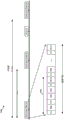
Fig. 7 is an exemplary diagram 700 illustrating a synchronization subframe structure for a millimeter wave communication system. The synchronization subframe may be divided into 14 symbols from symbol 0 to symbol 13. Within each symbol, 100 subcarriers may be transmitted, with the first 41 RBs used to carry BRS and PBCH, the next 18 RBs used to carry SSS, PSS, and ESS, and the next 41 RBs used to carry BRS and PBCH.
Peak-to-average power ratio (PAPR) advantages may be lost if different synchronization signals (for different synchronization channels) are frequency division multiplexed with each other. For example, if the base station transmits one type of synchronization signal (e.g., via a Zadoff Chu sequence), the base station may transmit at high power (e.g., with PAPR advantage). However, if a plurality of different types of synchronization signals (e.g., SSs, PSS, ESS, BRS, and PBCH within one symbol (e.g., within one SS block)) are simultaneously transmitted within one symbol as shown in fig. 7, PAPR becomes high and thus PAPR advantage may be lost. Therefore, frequency division multiplexing of synchronization signals with each other within each symbol may be undesirable in terms of PAPR advantages.
On the other hand, if different synchronization signals are time division multiplexed with each other, some PAPR advantage can be obtained. This PAPR advantage may be particularly apparent in channels carrying PSS and SSS channels. For example, Zadoff Chu sequences used in time division multiplexing of synchronization signals may provide PAPR advantages. In addition, if the time-division multiplexed synchronization signal is not frequency-division multiplexed with other signals, PAPR advantage can be maintained. Therefore, it may be desirable to time-multiplex some of the synchronization signals.
According to one aspect of the present disclosure, a base station processes synchronization signals by time-division multiplexing at least some of the synchronization signals (e.g., two or more synchronization signals), and then transmits the processed synchronization signals to a UE. The base station may avoid frequency division multiplexing of at least some of the synchronization signals. In one example, synchronization signals may be classified into a first synchronization signal comprising a PSS and a SSS, and a second synchronization signal comprising an ESS, a BRS and a PBCH signal. In another example, the first synchronization signal may include a PSS, SSS, BRS, ESS, or PBCH, and the second synchronization signal may include a PSS, SSS, BRS, ESS, or PBCH. In such an example, the base station may process the synchronization signals by time division multiplexing at least one synchronization signal from the first synchronization signal and at least one synchronization signal from the second synchronization signal. In this example, the base station may process the first synchronization signal by time-division multiplexing or frequency-division multiplexing the synchronization signal within the first synchronization signal, and may process the second synchronization signal by time-division multiplexing or frequency-division multiplexing the synchronization signal within the second synchronization signal. Subsequently, the base station may time-division multiplex the processed first synchronization signal and the processed second synchronization signal. In an aspect, the base station may avoid frequency division multiplexing the processed first synchronization signal and the processed second synchronization signal. In an aspect, the base station may avoid frequency division multiplexing any synchronization signal from the first synchronization signal and any synchronization signal from the second synchronization signal. In an aspect, a base station may avoid frequency division multiplexing of synchronization signals and data channel signals. In an aspect, the data channel signals may include PDSCH signals and/or PUSCH signals.
After processing the synchronization signal, the base station transmits the processed synchronization signal to the UE so that the UE can demultiplex the processed synchronization signal to synchronize with the base station. For example, the UE may demultiplex the processed synchronization signals by time-division demultiplexing at least one synchronization signal from the first synchronization signal and at least one synchronization signal from the second synchronization signal. For example, as previously discussed, the UE may demultiplex (e.g., time or frequency) a first multiplexed synchronization signal multiplexed (e.g., time or frequency divided) within a first synchronization signal and demultiplex (e.g., time or frequency divided) a second multiplexed synchronization signal multiplexed (e.g., time or frequency divided) within a second synchronization signal to produce a resulting synchronization signal, and may then perform time division demultiplexing of the resulting synchronization signal. In one example, the UE may perform time division demultiplexing of a first multiplexed synchronization signal time division multiplexed within a first synchronization signal and may perform time division demultiplexing of a second multiplexed synchronization signal time division multiplexed within a second synchronization signal to produce a resulting synchronization signal, and may then perform time division demultiplexing of the resulting synchronization signal. In another example, the UE may perform frequency division demultiplexing of a first multiplexed synchronization signal frequency division multiplexed within a first synchronization signal and may perform frequency division demultiplexing of a second multiplexed synchronization signal frequency division multiplexed within a second synchronization signal to produce a resulting synchronization signal, and may then perform time division demultiplexing of the resulting synchronization signal. In another example, the UE may perform time division demultiplexing of a first multiplexed synchronization signal time division multiplexed within a first synchronization signal and may perform frequency division demultiplexing of a second multiplexed synchronization signal frequency division multiplexed within a second synchronization signal to produce a resulting synchronization signal, and may then perform time division demultiplexing of the resulting synchronization signal.
In an aspect, a base station may transmit synchronization signals (e.g., to UEs) in synchronization signal blocks (SS blocks), where each SS block corresponds to a respective direction of a beam of the base station. When the base station transmits one or more sets of bursts, each set of bursts may include a set of SS blocks, where each SS block in the set of SS blocks may correspond to a respective beam direction. For example, in a scenario where a base station may scan in 16 directions using 16 beams, respectively, a burst set may contain 16 SS blocks, where each SS block corresponds to a different direction of the respective beam. The PSS or SSS may be used to transmit the SS block index within the burst set. For example, in mmW communication, a base station may transmit PSS, SSS, and PBCH for each beam direction. In one example, the combination of PSS, SSS, and PBCH may constitute one SS block. In such an example, the burst set may include 16 SS blocks (e.g., in 16 directions) or 32 SS blocks (e.g., in 32 directions).
In an aspect, a synchronization channel subframe (e.g., a synchronization subframe) may include a processed synchronization signal including a set of synchronization signals (PSS, SSS, and PBCH signals) that have been processed and one or more repetitions of the processed synchronization signal. In an aspect, in case that the processed synchronization signal is repeated one or more times, the synchronization channel subframe may further include the synchronization signal that is not repeated. The non-repeating synchronization signals may indicate time and/or frequency locations of the repeated synchronization signals (e.g., time and/or frequency locations of PSS, SSS, and PBCH signals). The non-repeating synchronization signal may be an ESS. In one aspect, the processed synchronization signals may include a set of synchronization signals such as PSS, SSS, and PBCH signals. One or more of the synchronization signals may be repeated within the processed synchronization signal. In one example, the processed synchronization signals may include PSS, SSS, repeated SSS, and PBCH signals. In one example, the processed synchronization signals may include PSS, SSS, PBCH, and repeated PBCH signals. In one example, the processed synchronization signals may include a PSS, a SSS, a DMRS for a PBCH signal, and a repeated DMRS. In one aspect, the synchronization signal and the repetitions of the synchronization signal may be temporally adjacent to each other in the processed synchronization signal. In another aspect, the synchronization signal and the repetitions of the synchronization signal may be separated in time from each other in the processed synchronization signal. Repetition of the synchronization signal within the processed synchronization signal may provide additional benefits in that: the repetition of the synchronization signal and the synchronization signal allows for frequency error estimation based on the repetition of the synchronization signal and the synchronization signal (e.g., by estimating a carrier frequency offset, as previously described). In an aspect, within a synchronization subframe, a set of SS blocks may be transmitted, where each SS block in the set of SS blocks may correspond to a respective beam direction and may include a processed synchronization signal. Thus, in such an aspect, one or more of the synchronization signals may be repeated within the SS block.
In an aspect, the ESS may be used (e.g., by the UE) to identify the symbol and slot/subframe index of the detected/received synchronization signal. In an aspect, a demodulation reference signal (DMRS) for a PBCH signal may be used (e.g., instead of ESS) to identify the symbol and slot/subframe index of the detected/received synchronization signal. In one aspect, the ESS may be used to identify a portion of the SS block index or the entire SS block index. In one aspect, the ESS may be used to identify a portion of or the entire symbol and slot/subframe index of the detected/received synchronization signal. In an aspect, DMRS for PBCH signals may be used to act as ESS. Thus, in such aspects, for example, the DMRS for the PBCH signal may convey a portion of or the entire symbol and slot/subframe index of the detected/received synchronization signal. For example, the DMRS for the PBCH signal may transmit a portion of the SS block index or the entire SS block index.
In one aspect, the base station may set the digital scheme such that the digital scheme (e.g., tone spacing) for the synchronization signal is different from the digital scheme (e.g., tone spacing) for the data signal. The digital scheme (e.g., tone spacing) for the synchronization signal may be greater than the digital scheme (e.g., tone spacing) for the data signal. The base station may transmit the synchronization signal based on a digital scheme for the synchronization signal and may transmit the data signal based on a digital scheme for the data signal. The synchronization signals may include one or more of PSS, SSS, BRS, ESS, and PBCH. The data signals may include one or more PDSCH signals. In an aspect, the PDSCH signals may carry Remaining Minimum System Information (RMSI) and/or Other System Information (OSI). In an aspect, the digital scheme for the data signal may indicate a digital scheme of RMSI and/or OSI. In one aspect, the digital scheme used for the signal may determine the duration (e.g., period) of transmission of the signal transmitted by the base station. For example, the duration (e.g., period) of transmission of the processed synchronization signal may be a function of the tone spacing and/or the digital scheme used for the processed synchronization signal. For example, the duration (e.g., period) of transmission of the data signal may be a function of the digital scheme and/or tone spacing used for the data signal. The base station may use a digital scheme for the processed synchronization signal and/or a digital scheme for the data signal. The data signals may include PDSCH signals and/or PUSCH signals. The base station may declare such numerology information and/or tone spacing in the system information sent to the UE. The system information may be a Master Information Block (MIB) and/or a System Information Block (SIB). The MIB may be transmitted via PBCH signals. SIBs may be transmitted via RMSI and/or OSI. In another aspect, the duration of the transmission of the signal may be a fixed value regardless of the digital scheme used. Since the digital scheme information is provided to the UE (e.g., via system information), when the UE receives the synchronization signal, the UE may receive the synchronization signal in consideration of the corresponding digital scheme. When the UE receives the data signal, the UE may receive the data signal in consideration of a corresponding digital scheme. For example, the UE may consider the tone spacing for the synchronization signal when receiving the synchronization signal and the tone spacing for the data signal when receiving the data signal.
In an aspect, the base station may signal the UE to associate a beam with a PRACH and/or scheduling request occasion by broadcast or unicast. In one example, such an association may provide benefits for downlink and uplink beamforming if the base station is configured to scan in different directions via beamforming. In another example, if the system is not configured to scan in different directions via beamforming, the UE may again use LTE PRACH resource association because the UE may detect multiple beams, each with similar strength. In an aspect, a base station may transmit system information to a UE to indicate whether a processed synchronization signal is transmitted multiple times in different directions or multiple times in the same direction. The system information may be, for example, MIB or SIB. The UE may then determine which resources to use for RACH transmission by the UE based on the system information and/or the received synchronization signals.
In one aspect, different multiplexing combinations of synchronization signals may be used. According to one approach, a base station may be configured to utilize time division multiplexing without frequency division multiplexing for all types of synchronization signals. According to another approach, the base station may be configured to utilize both time division multiplexing and frequency division multiplexing of the synchronization signals. For example, a base station may generate a first processed signal by frequency division multiplexing the PSS and SSS, and may generate a second processed signal by frequency division multiplexing the PBCH signal and the BRS. The base station may then time-division multiplex the first processed signal and the second processed signal to generate a processed synchronization signal. When PSS and SSS are frequency division multiplexed, PSS may be mapped to consecutive tones in a first subset of tones, and SSS may be mapped to spaced-apart tones (e.g., equally spaced-apart tones) in a second subset of tones. Thus, for example, in the second subset of tones, tones mapped with SSS occur in every N tones, where N is an integer.
Fig. 8 is an example diagram 800 illustrating communication between a user equipment and a base station in accordance with an aspect of the disclosure. Example diagram 800 relates to communications between a UE 802 and a base station 804. In the example diagram 800, a base station 804 has fourteen antenna ports that can be beamformed in fourteen directions. At 812, the base station 804 processes a set of synchronization signals, which includes time-division multiplexing at least some of the synchronization signals (e.g., two or more). Subsequently, the base station 804 transmits the set of processed synchronization signals within the synchronization subframe and repeatedly transmits the set of processed synchronization signals in different beam directions via beamforming. In particular, at 814, the base station 804 transmits the set of processed synchronization signals via beamforming in a first direction. At 816, the base station 804 repeatedly transmits the set of processed synchronization signals via beamforming in a second direction. The base station 804 may repeatedly transmit the set of processed synchronization signals to transmit the processed synchronization signals in each of the fourteen different directions via beamforming. The base station may repeatedly transmit the set of processed synchronization signals within the synchronization subframe. At 820, the base station 804 repeatedly transmits the set of processed synchronization signals via beamforming in fourteen directions. For example, the UE 802 may receive a beam transmitted in a direction close to the direction of the UE 802 to achieve optimal reception of the synchronization signal. At 822, the UE 802 demultiplexes the set of processed synchronization signals to obtain the synchronization signals.
In an aspect, after 820, in a subsequent synchronization subframe, the base station 804 may process the second set of synchronization signals and transmit the second set of processed synchronization signals to the UE. The second set of synchronization signals may be different from the set of synchronization signals processed at 812. The base station 804 may transmit the second set of processed synchronization signals in a subsequent synchronization subframe and repeatedly transmit the second set of processed synchronization signals in a different beam direction via beamforming.
Fig. 9 is an example diagram 900 illustrating transmission of a synchronization signal in accordance with an aspect of the present disclosure. A base station may transmit synchronization signals (such as PSS, SSS, and PBCH signals) twice within one radio frame. In this example, since the radio frame is 10 milliseconds long, the base station may transmit the synchronization signal once every 5 milliseconds. In particular, the base station may first transmit a synchronization signal using a first synchronization channel 912 within the radio frame, and then transmit the synchronization signal later in the radio frame using a second synchronization channel 914. RACH 916 may occur after second synchronization channel 914. In this example, the base station processes the synchronization signals such that a cyclic prefix exists between the synchronization signals in the processed synchronization signals 952. As discussed above, the synchronization signals may be processed by time division multiplexing the PSS, SSS, and PBCH, which results in the processed synchronization signal 952. In this case, since there are fourteen symbols, the transmission of the processed synchronization signal 952 (e.g., per symbol) can be performed fourteen times in fourteen directions via beamforming in a scanned manner (e.g., scanning the beam in fourteen directions to cover the entire sector). The tone spacing for each of the synchronization signals in the processed synchronization signals 952 may be 120 kHz. The PBCH signal may be frequency division multiplexed with the BRS and/or ESS.
Fig. 10 is an example diagram 1000 illustrating transmission of a synchronization signal in accordance with an aspect of the present disclosure. A base station may transmit synchronization signals (such as PSS, SSS, and PBCH signals) twice within one radio frame. In this example, since the radio frame is 10 milliseconds long, the base station may transmit the synchronization signal once every 5 milliseconds. In particular, the base station may first transmit a synchronization signal using a first synchronization channel 1012 within the radio frame, and then transmit the synchronization signal later in the radio frame using a second synchronization channel 1014. RACH 1016 may occur after second synchronization channel 1014. In this example, the base station processes the synchronization signals such that there is a cyclic prefix between the synchronization signals in the processed synchronization signals 1052. As discussed above, the synchronization signals may be processed by time division multiplexing the PSS, SSS, and PBCH, which results in processed synchronization signals 1052. In this case, since there are fourteen symbols, the transmission of the processed synchronization signal 1052 (e.g., per symbol) can be performed fourteen times in fourteen directions via beamforming in a scanning manner (e.g., to cover the entire sector). The base station may transmit the processed synchronization signal 1052 four times for each beamforming direction. Therefore, when the processed synchronization signal 1052 is transmitted in fourteen directions, the base station transmits the processed synchronization signal 1052 fifty-six times in total (14x4 ═ 56). For each beamforming direction, since the base station transmits the processed synchronization signal 1052 four times, the UE may receive the processed synchronization signal 1052 in different antenna sub-arrays (e.g., 4 sub-arrays) of the UE and may determine the antenna sub-array that provides the optimal result (e.g., the optimal signal-to-noise ratio of the received synchronization signal). Each antenna sub-array of the UE may correspond to a particular direction. The tone spacing for each of the processed synchronization signals 1052 may be 120 kHz. The received PBCH signal may be frequency division multiplexed with the BRS and/or ESS.
In one aspect, the base station may transmit the processed synchronization signal 1052 four times in succession in each of the fourteen directions. For example, in this aspect, the base station may transmit in direction 1, direction 2 …, direction 14. In another aspect, the base station may transmit the processed synchronization signal 1052 four times in each of the fourteen directions in a scanning manner. For example, in this aspect, the base station may transmit in direction 1, 2 … 14, in direction 1, 2 … 14, in direction 1, 2 … 14, and in direction 1, 2 … 14.
Fig. 11A and 11B are example diagrams 1100 and 1170 illustrating transmission of a synchronization signal, according to aspects of the present disclosure. Fig. 11A is an example diagram 1100 illustrating transmission of synchronization signals within a radio frame, in accordance with an aspect of the present disclosure. A base station may transmit synchronization signals (such as PSS, SSS, and PBCH signals) twice within one radio frame. As shown in fig. 11A, since the radio frame is 10 msec long, the base station can transmit the synchronization signal once every 5 msec. In particular, the base station may first transmit a synchronization signal using a first synchronization channel 1112 within the radio frame, and then transmit the synchronization signal again later in the radio frame using a second synchronization channel 1114. RACH 1116 may occur after second synchronization channel 1114.
In the example shown in fig. 11A and 11B, the base station processes the synchronization signals to insert a cyclic prefix between the synchronization signals in the processed synchronization signals 1152. Since there are fourteen symbols, the transmission of the processed synchronization signals 1152 (e.g., each symbol) can be performed fourteen times in fourteen directions via beamforming in a scanning manner (e.g., to cover the entire sector). The processed synchronization signal 1152 corresponds to the time-division multiplexed synchronization signal 1170 shown in fig. 11B. Specifically, when the base station determines to transmit the synchronization signal, the base station performs time division multiplexing of the synchronization signal to generate a time-division multiplexed synchronization signal 1170, and then transmits the time-division multiplexed synchronization signal 1170 as a processed synchronization signal 1152 in one symbol. As shown in fig. 11B, to generate the time division multiplexed synchronization signal 1170, the synchronization signal is processed by time division multiplexing of the frequency division multiplexing of the PSS 1172 and the SSS 1174 with the PBCH/BRS 1176. As shown in fig. 11B, within one symbol (e.g., within one SS block), the PSS 1172 and the SSs 1174 may be transmitted during the same time period and in different resource blocks, and then the PBCH/BRS 1176 may be transmitted in the same time period and in the same resource block. PBCH/BRS (block) 1176 may be generated by frequency division multiplexing the PBCH and BRS signals. The BRS signal may be used as a beam reference signal for the UE. The BRS signal may also be used as a reference signal for PBCH tones. The PBCH tone may also have its own demodulation reference signal. Thus, during transmission of the processed synchronization signal 1152 in one symbol, the base station transmits PSS and SSS during a first time period 1154 and PBCH and BRS during a second time period 1156, with a cyclic prefix prior to the start of each of the first and second time periods 1154 and 1156. The tone spacing for each of the processed synchronization signals in synchronization signal 1152 may be 240 kHz. The PBCH signal may be frequency division multiplexed with the BRS and/or ESS.
Fig. 12A and 12B are example diagrams 1200 illustrating transmission of a synchronization signal, in accordance with aspects of the present disclosure. Fig. 12A is an example diagram 1200 illustrating transmission of synchronization signals in a radio frame, in accordance with an aspect of the present disclosure. A base station may transmit one or more synchronization signals (such as PSS, SSS, and PBCH signals) twice within one radio frame. In this example, since the radio frame is 10 milliseconds long, the base station may transmit the synchronization signal once every 5 milliseconds. In particular, the base station may first transmit a synchronization signal using a first synchronization channel 1212 within the radio frame and then repeat the transmission of the synchronization signal later in the radio frame using a second synchronization channel 1214. RACH 1216 may occur after second synchronization channel 1214. In this example, the base station processes the synchronization signals such that a cyclic prefix exists between different ones of the processed synchronization signals 1252.
In this aspect of the disclosure, the base station may process the synchronization signals such that one or more synchronization signals may be repeated in the processed synchronization signal 1252. In this example, the SSS repeats in the processed synchronization signal 1252. As discussed above, the synchronization signals may be processed by time division multiplexing the PSS, SSS, and PBCH/BRS. In this case, since there are fourteen symbols, the transmission of the processed synchronization signals 1252 (e.g., each symbol) can be performed fourteen times in fourteen directions via beamforming in a scanning manner (e.g., to cover the entire sector). The processed synchronization signal 1252 corresponds to the time-division multiplexed synchronization signal 1270 shown in fig. 12B. Specifically, when the base station determines to transmit the synchronization signal, the base station performs time division multiplexing of the synchronization signal to generate a time-division multiplexed synchronization signal 1270, and then transmits the time-division multiplexed synchronization signal 1270 as the processed synchronization signal 1252 in one symbol. As shown in fig. 12B, the synchronization signals may be processed by time division multiplexing the PSS 1272, the SSS 1274, the repetitions of the SSS 1276, and the PBCH/BRS 1278. In an aspect, the PBCH/BRS block may be generated by frequency division multiplexing the PBCH signal and the BRS signal. As further shown in fig. 12B, within one symbol (e.g., within one SS block), the PSS 1272, the SSs 1274, the repetitions of the SSs 1276, and the PBCH/BRS 1278 may be transmitted in different time periods. Thus, as shown in fig. 12A, during transmission of the processed synchronization signal 1252 in one symbol, a base station may transmit a PSS during a first time period 1254, a repetition of an SSS and an SSS during a second time period 1256, and a PBCH/BRS during a third time period 1258, with a cyclic prefix prior to the start of each of the first, second, and third time periods 1254, 1256, and 1258. The tone spacing for each of the processed synchronization signals in synchronization signal 1252 may be 120 kHz. The PBCH signal may be frequency division multiplexed with the BRS and/or ESS.
Fig. 13 is an example diagram 1300 illustrating transmission of a synchronization signal in accordance with an aspect of the present disclosure. A base station may transmit synchronization signals (such as PSS, SSS, and PBCH signals) twice within one radio frame. In this example, since the radio frame is 10 milliseconds long, the base station may transmit the synchronization signal once every 5 milliseconds. Fig. 13 shows the same diagram as the example diagram 1200 of fig. 12A, and thus, for the sake of brevity, an explanation of the processed synchronization signal 1352 is partially omitted. The tone spacing is inversely proportional to the symbol duration. The tone spacing for one synchronization signal may be different from the tone spacing for another synchronization signal. For example, in the processed synchronization signal 1352, the PSS has a tone spacing of 480kHz and a duration of 2.083 microseconds, and the PBCH signal has a tone spacing of 480kHz and a duration of 2.083 microseconds. In the processed synchronization signal 1352, the tone spacing is 240kHz for SSS and the duration is 4.167 microseconds. The SSS occupies one tone in every two tones, and the length of the SSS may be 63 sequences. The CP duration of PSS and PBCH is 148.81ns, and the CP duration of SSS is 297.62 ns. There are 14 symbols with a 120kHz tone spacing in each subframe.
Fig. 14A and 14B are example diagrams 1400 illustrating transmission of a synchronization signal, in accordance with aspects of the present disclosure. Fig. 14A is an example diagram 1400 illustrating transmission of synchronization signals over radio frames, in accordance with an aspect of the present disclosure. A base station may transmit synchronization signals (such as PSS, SSS, and PBCH signals) twice within one radio frame. In this example, since the radio frame is 10 milliseconds long, the base station may transmit the synchronization signal once every 5 milliseconds. In particular, the base station may first transmit the synchronization signal using a first synchronization channel 1412 within the radio frame, and then transmit the synchronization signal again later in the radio frame using a second synchronization channel 1414. RACH 1416 may occur after second synchronization channel 1414. The base station can process the synchronization signals such that a cyclic prefix exists between different ones of the processed synchronization signals 1452.
In this aspect of the disclosure, the base station may process the synchronization signals such that one or more synchronization signals may be repeated in the processed synchronization signal 1452. The PBCH/BRS may be repeated in the processed synchronization signal 1452. As discussed above, the synchronization signals may be processed by time division multiplexing the PSS, SSS, and PBCH/BRS. In this case, since there are fourteen symbols, the transmission of the processed synchronization signal 1452 (e.g., each symbol) can be performed fourteen times in fourteen directions via beamforming in a scanning manner (e.g., to cover the entire sector). Thus, the transmission of processed synchronization signal 1452 may be performed fourteen times within first synchronization channel 1412. The processed synchronization signal 1452 with the cyclic prefix corresponds to the time-division multiplexed synchronization signal 1470 shown in fig. 14B. In particular, when the base station determines to transmit the synchronization signal, the base station may perform time division multiplexing of the synchronization signal to generate a time division multiplexed synchronization signal 1470, and then transmit the time division multiplexed synchronization signal 1470 as the processed synchronization signal 1452 in one symbol. In this example, as shown in fig. 14B, the synchronization signals may be processed by time division multiplexing of PSS 1472, SSS 1474, PBCH/BRS 1476, and repetitions 1478 of PBCH/BRS. In one aspect, the PBCH/BRS block may be generated by frequency division multiplexing of PBCH and BRS signals. As shown in fig. 14B, within one symbol (e.g., within one SS block), the PSS 1472, SSs 1474, PBCH/BRS 1476, and repetitions of PBCH/BRS 1478 may be transmitted in different time periods. Thus, as shown in fig. 14A, during transmission of the processed synchronization signal 1452 in one symbol, the base station may transmit a PSS during a first time period 1454, an SSS during a second time period 1456, and repetitions of PBCH/BRS and PBCH/BRS during a third time period 1458, with a cyclic prefix prior to the start of each of the first, second, and third time periods 1454, 1456, 1458. The tone spacing for each of the processed synchronization signals in synchronization signals 1452 may be 120 kHz. The PBCH signal may be frequency division multiplexed with the BRS and/or ESS.
Fig. 15A and 15B are example diagrams 1500 illustrating transmission of synchronization signals, in accordance with aspects of the present disclosure. Fig. 15A is an example diagram 1500 illustrating transmission of synchronization signals over radio frames, in accordance with an aspect of the present disclosure. A base station may transmit synchronization signals (such as PSS, SSS, and PBCH signals) twice within one radio frame. In this example, since the radio frame is 10 milliseconds long, the base station may transmit the synchronization signal once every 5 milliseconds. In particular, the base station may first transmit a synchronization signal using a first synchronization channel 1512 within the radio frame, and then transmit the synchronization signal later in the radio frame using a second synchronization channel 1514. RACH 1516 may occur after second synchronization channel 1514. The base station may process the synchronization signals such that a cyclic prefix exists between different ones of the processed synchronization signals 1552.
In this aspect of the disclosure, the base station may process the synchronization signals such that one or more synchronization signals may be repeated in the processed synchronization signal 1552, wherein the repetitions of the synchronization signal and the synchronization signal are spaced apart in time during time division multiplexing. In this example, the SSS may be repeated in the processed synchronization signal 1552. As discussed above, the synchronization signals may be processed by time division multiplexing the PSS, SSS, and PBCH/BRS. In this case, since there are fourteen symbols, transmission of processed synchronization signals 1552 (e.g., each symbol) may be performed fourteen times in fourteen directions via beamforming in a scanning manner (e.g., to cover the entire sector). The processed synchronization signal 1552 with the cyclic prefix may correspond to the time-division multiplexed synchronization signal 1570 shown in fig. 15B. In particular, when the base station determines to transmit the synchronization signal, the base station may perform time division multiplexing of the synchronization signal to generate a time division multiplexed synchronization signal 1570, and then transmit the time division multiplexed synchronization signal 1570 as the processed synchronization signal 1552 in one symbol. As shown in fig. 15B, synchronization signals may be processed by time division multiplexing the PSS 1572, the SSS 1574, the PBCH/BRS 1576, and the repetitions 1578 of the SSS, wherein the SSS 1574 and the repetitions 1578 of the SSS are spaced apart from each other in time, wherein the PBCH/BRS 1576 is between the SSS 1574 and the repetitions 1578 of the SSS. In an aspect, the PBCH/BRS block may be generated by frequency division multiplexing the PBCH signal and the BRS signal. As shown in fig. 15B, within one symbol (e.g., within one SS block), repetitions 1578 of PSS 1572, SSs 1574, PBCH/BRS 1576, and SSs may be transmitted in different time periods. Thus, as shown in fig. 15A, during transmission of the processed synchronization signal 1552 in one symbol, a base station may transmit a PSS during a first time period 1554, an SSS during a second time period 1556, and a PBCH/BRS in a third time period 1558, and a repetition of the SSS during a fourth time period 1560, with a cyclic prefix prior to the start of each of the first time period 1554, the second time period 1556, the third time period 1558, and the fourth time period 1560. The tone spacing for each of the synchronization signals in the processed synchronization signals 1552 may be 120 kHz. The PBCH signal may be frequency division multiplexed with the BRS and/or ESS.
Fig. 16A and 16B are example diagrams 1600 illustrating transmission of a synchronization signal, in accordance with aspects of the present disclosure. Fig. 16A is an example diagram 1600 illustrating transmission of synchronization signals over radio frames in accordance with an aspect of the present disclosure. A base station may transmit synchronization signals (such as PSS, SSS, and PBCH signals) twice within one radio frame. In this example, since the radio frame is 10 milliseconds long, the base station may transmit the synchronization signal once every 5 milliseconds. In particular, the base station may first transmit a synchronization signal using a first synchronization channel 1612 within the radio frame, and then transmit the synchronization signal later in the radio frame using a second synchronization channel 1614. RACH 1616 may occur after second synchronization channel 1614. The base station may process the synchronization signals such that a cyclic prefix exists between different ones of the processed synchronization signals 1652.
In this aspect of the disclosure, the base station may process the synchronization signals such that one or more synchronization signals may repeat in the processed synchronization signal 1652, where the repetitions of the synchronization signal and the synchronization signal are spaced apart in time during time division multiplexing. The PBCH/BRS may be repeated in the processed synchronization signal 1652. As discussed above, the synchronization signals may be processed by time division multiplexing the PSS, SSS, and PBCH/BRS. In this case, since there are fourteen symbols, the transmission of the processed synchronization signal 1652 (e.g., each symbol) can be performed fourteen times in fourteen directions via beamforming in a scanning manner (e.g., to cover the entire sector). The processed synchronization signal 1652 with the cyclic prefix may correspond to the time-division multiplexed synchronization signal 1670 shown in fig. 16B. In particular, when the base station determines to transmit the synchronization signal, the base station may perform time division multiplexing of the synchronization signal to generate a time division multiplexed synchronization signal 1670, and then transmit the time division multiplexed synchronization signal 1670 as the processed synchronization signal 1652 having the cyclic prefix in one symbol. In one aspect, the PBCH/BRS block may be generated by frequency division multiplexing of PBCH and BRS signals. As shown in fig. 16B, synchronization signals may be processed by time division multiplexing PBCH/BRS 1672, PSS 1674, SSS 1676, and repetitions 1678 of PBCH/BRS, where PBCH/BRS 1672 and repetitions 1678 of PBCH/BRS are spaced apart in time from one another, where PSS 1674 and SSS 1676 are between PBCH/BRS 1672 and repetitions 1678 of PBCH/BRS. As shown in fig. 16B, within one symbol (e.g., within one SS block), PBCH/BRS 1672, PSS 1674, SSs 1676, and repetitions 1678 of PBCH/BRS may be transmitted in different time periods. Thus, as shown in fig. 16A, during transmission of the processed synchronization signal 1652 in one symbol, the base station may transmit a PBCH/BRS during a first time period 1654, a PSS during a second time period 1656, and a SSS during a third time period 1658, and a repetition of the PBCH/BRS during a fourth time period 1660, with a cyclic prefix prior to the beginning of each of the first time period 1654, the second time period 1656, the third time period 1658, and the fourth time period 1660. The pitch interval for each of the processed synchronization signals 1652 may be 120 kHz. The PBCH signal may be frequency division multiplexed with the BRS and/or ESS.
Fig. 17A and 17B are example diagrams 1700 illustrating transmission of a synchronization signal, in accordance with aspects of the present disclosure. Fig. 17A is an example diagram 1700 illustrating transmission of synchronization signals over radio frames in accordance with an aspect of the present disclosure. The base station may transmit synchronization signals (such as PSS, SSS, and PBCH signals) twice in two sessions within one radio frame (e.g., a first session using the first synchronization channel 1712 and a second session using the second synchronization channel 1714). In this example, since the radio frame is 10 milliseconds long, the base station may transmit the synchronization signal once every 5 milliseconds. In particular, the base station may first transmit a synchronization signal using a first synchronization channel 1712 within the radio frame (e.g., during a first synchronization subframe) and then later transmit a synchronization signal using a second synchronization channel 1714 (e.g., during a second synchronization subframe). RACH 1716 may occur after second synchronization channel 1714. In this example, the base station may process the synchronization signals such that a cyclic prefix exists between different ones of the processed synchronization signals 1732.
In this aspect of the disclosure, the base station may process the synchronization signal such that the PBCH signal may be repeated in the processed synchronization signal 1732. In one aspect, the PBCH signal and the repeated PBCH signal may be spaced apart in time (e.g., for estimation of carrier frequency offset, as previously discussed) during time division multiplexing. The PBCH signal may be repeated in the processed synchronization signal 1732. As discussed above, the synchronization signals may be processed by time division multiplexing the PSS, SSS, and PBCH. In this case, since there are fourteen symbols, the transmission of the processed synchronization signals 1732 (e.g., each symbol) can be performed fourteen times in fourteen directions via beamforming in a scanning manner (e.g., to cover the entire sector). The processed synchronization signal 1732 with the cyclic prefix may correspond to the time-division multiplexed synchronization signal 1770 shown in fig. 17B. In particular, when the base station determines to transmit the synchronization signal, the base station may perform time division multiplexing of the synchronization signal to generate a time division multiplexed synchronization signal 1770 and then transmit the time division multiplexed synchronization signal 1770 in one nominal symbol (e.g., 17.89 microseconds) as the processed synchronization signal 1732 with the cyclic prefix.
As shown in fig. 17B, synchronization signals may be processed by time division multiplexing PBCH 1772, PSS 1774, SSS 1776, and repetitions 1778 of PBCH, where PBCH 1772 and repetitions 1778 of PBCH may be spaced apart from each other in time, where PSS 1774 and SSS 1776 are between PBCH 1772 and repetitions 1778 of PBCH (e.g., for estimation of carrier frequency offset, as previously discussed). PBCH 1772 and repetition 1778 of PBCH may be the same in that: the signals transmitted for repetition 1778 of the PBCH and the antenna ports and beams used for transmission of repetition 1778 of the PBCH are the same as those used for transmission of PBCH 1778. While the order of PSS 1774 and SSS 1776 in time-multiplexed synchronization signal 1770 shows PSS 1774 preceding SSS 1767, in another example, the order may be reversed. As shown in fig. 17B, the bandwidths of PBCH 1772, PSS 1774, SSS 1776, and repetition 1778 of PBCH may be the same. For example, the bandwidth may be 36MHz (150 REs with 24kHz tone spacing). However, in another example, the bandwidth of PSS may be less than the bandwidth of SSS and/or the bandwidth of PBCH/repeated PBCH.
As shown in fig. 17B, repetitions 1778 of PBCH 1772, PSS 1774, SSS 1776, and PBCH may be transmitted in different time periods within one nominal symbol. Thus, as shown in fig. 17A, during transmission of the processed synchronization signal 1732 in one symbol, the base station may transmit a PBCH during a first time period 1734, a PSS during a second time period 1736, and a SSS during a third time period 1738, and a repetition of the PBCH during a fourth time period 1740 with a cyclic prefix prior to the beginning of each of the first time period 1734, the second time period 1736, the third time period 1738, and the fourth time period 1740. Each of the first time period 1734, the second time period 1736, the third time period 1738, and the fourth time period 1740 may correspond to an OFDM symbol. The tone spacing for each of the synchronization signals in processed synchronization signals 1732 may be 120 kHz. For example, each OFDM symbol may have 4 times the nominal subcarrier spacing and thus may have 1/4 times the length of time of the nominal symbol. Thus, the nominal symbol duration may be divided into four OFDM symbols, where the four OFDM symbols correspond to transmission times for PBCH 1772, PSS 1774, SSS 1776, and repetitions 1778 of PBCH, respectively.
Fig. 18A and 18B are example diagrams 1800 illustrating transmission of synchronization signals, in accordance with aspects of the present disclosure. Fig. 18A is an example diagram 1800 illustrating transmission of synchronization signals over radio frames in accordance with an aspect of the present disclosure. The base station may transmit a first set of synchronization signals (including PSS, SSS, and PBCH signals) in one session (e.g., using the first synchronization channel 1812) and may transmit a second set of synchronization signals (including PSS, SSS, and BRS signals) in a subsequent session (e.g., using the second synchronization channel 1814) within one radio frame. In particular, during the first synchronization subframe, the base station may transmit the first set of processed synchronization signals multiple times (e.g., 14 times) using multiple beams in different directions. During the second synchronization subframe, the base station may transmit the second set of processed synchronization signals multiple times (e.g., 14 times) using multiple beams in different directions. Thus, for example, if the base station transmits the first set of processed synchronization signals 14 times, 14 transmit beams in 14 directions are used for such transmission, and if the base station transmits the second set of processed synchronization signals 14 times, the same 14 transmit beams in the same 14 directions are used for such transmission. That is, in this example, the 1 st to 14 th beams for the first synchronization subframe may correspond to the 1 st to 14 th beams for the second synchronization subframe, respectively.
In the example diagram 1800 of fig. 18A, since the radio frame is 10 milliseconds long, the base station may transmit the synchronization signal once every 5 milliseconds. In particular, the base station may first transmit a first set of synchronization signals (e.g., during a first synchronization subframe) using a first synchronization channel 1812 within the radio frame, and then transmit a second set of synchronization signals (e.g., during a second synchronization subframe) at a later time/subframe of the radio frame using a second synchronization channel 1814. RACH 1816 may occur after second synchronization channel 1814. The base station may process the synchronization signals such that a cyclic prefix exists between different ones of the processed synchronization signals 1832.
In this aspect of the disclosure, during the first synchronization subframe, the base station may process the synchronization signal such that the PBCH signal may be repeated in the processed synchronization signal 1832. For example, during a first synchronization subframe, a base station may transmit a first set of synchronization signals including repetitions of PBCH, PSS, SSS, and PBCH. In one aspect, the PBCH signal and the repeated PBCH signal may be spaced apart in time (e.g., for estimation of carrier frequency offset, as previously discussed) during time division multiplexing. Processing and transmitting synchronization signals using the first synchronization channel 1812 during the first synchronization subframe may be similar to processing and transmitting synchronization signals using the first synchronization channel 1712 during the first synchronization subframe, as discussed above with reference to fig. 17A and 17B. Further, the processed synchronization signal 1832 may correspond to a time-multiplexed synchronization signal similar to the time-multiplexed synchronization signal 1770 shown in fig. 17B. Therefore, a detailed explanation of the processed synchronization signal 1832 and the corresponding time-division multiplexed synchronization signal is omitted.
During the second synchronization subframe, the base station may process the synchronization signal such that the BRS signal may be repeated in the processed synchronization signal 1852. For example, during a second synchronization subframe, the base station may transmit a second set of synchronization signals comprising repetitions of BRS, PSS, SSS, and BRS. In one aspect, the BRS signal and the repeated BRS signal may be spaced apart in time during time division multiplexing. The BRS signal may be repeated in the processed synchronization signal 1852. As discussed above, the synchronization signals may be processed by time-division multiplexing the PSS, SSS, and BRS. In this case, since there are fourteen symbols, the transmission of the processed synchronization signal 1852 (e.g., each symbol) can be performed fourteen times in fourteen directions via beamforming in a swept manner (e.g., to cover the entire sector). The processed synchronization signal 1852 with the cyclic prefix may correspond to the time-division multiplexed synchronization signal 1880 shown in fig. 18B. In particular, when the base station determines to transmit the synchronization signal, the base station may perform time division multiplexing of the synchronization signal to generate a time division multiplexed synchronization signal 1880, and then transmit the time division multiplexed synchronization signal 1880 as the processed synchronization signal 1852 having the cyclic prefix in one nominal symbol (e.g., 17.89 microseconds). As shown in fig. 18B, the synchronization signal may be processed by time division multiplexing the BRS 1882, PSS 1884, SSS 1886, and repetitions 1888 of the BRS, where the BRS 1882 and repetitions 1888 of the BRS may be spaced apart from one another in time, where the PSS 1884 and SSS 1886 are between the BRS 1882 and the repetitions 1888 of the BRS. The repetitions 1888 of the BRS 1882 and the BRS may be the same in that: the signals transmitted for the repetition 1888 of the BRS and the antenna ports and beams used for the transmission of the repetition 1888 of the BRS are the same as those used for the transmission of the BRS 1888. While the order of the PSS 1884 and SSS 1886 in the time division multiplexed synchronization signal 1880 shows the PSS 1884 preceding the SSS 1887, in another example, the order may be reversed. As shown in fig. 18B, the bandwidth of the repetitions 1888 of BRS 1882, PSS 1884, SSS 1886, and BRS may be the same. For example, the bandwidth may be 36 MHz. In another aspect, the bandwidth of the BRS ( repetitions 1882 or 1888 of the BRS) may be wider than the bandwidth of the PBCH/repeated PBCH.
As shown in fig. 18B, repetitions 1888 of BRS 1882, PSS 1884, SSS 1886, and BRS may be transmitted in different time periods within one nominal symbol. Thus, as shown in fig. 18A, during transmission of the processed synchronization signal 1852 in one symbol, the base station may transmit a PBCH during a first time period 1854, a PSS during a second time period 1856, and an SSS during a third time period 1858, and a repetition of the PBCH during a fourth time period 1860, with a cyclic prefix prior to the start of each of the first, second, third, and fourth time periods 1854, 1856, 1858, and 1860. Each of the first, second, third, and fourth time periods 1854, 1856, 1858, and 1860 may correspond to an OFDM symbol. The tone spacing for each of the synchronization signals in the processed synchronization signals 1852 may be 120 kHz. For example, each OFDM symbol may have 4 times the nominal subcarrier spacing and thus may have 1/4 times the length of time of the nominal symbol. Thus, the nominal symbol duration may be divided into four OFDM symbols, where the four OFDM symbols correspond to the transmission times for repetitions 1888 of BRS 1882, PSS 1884, SSS 1886, and BRS, respectively.
In an aspect, the UE may estimate the channel within the 36MHz bandwidth using SSS (which is transmitted in all subframes) or may estimate the channel within the 36MHz bandwidth using BRS (which is transmitted in every other subframe). Further, the UE may use BRS (which is transmitted in every other subframe) to estimate channels outside of the 36MHz bandwidth.
In an aspect, the UE may determine whether the UE is receiving a signal in a first synchronization subframe or a second synchronization subframe. The UE may receive and decode a PBCH from the signal if the UE determines that the UE is receiving the signal in the first synchronization subframe. If the UE determines that the UE is receiving a signal in the second synchronization subframe, the UE may receive and decode a BRS from the signal. Decoding the BRS may include detecting a beam identifier, measuring RSRP or other beam quality measurements, and estimating a channel for one or more beams.
In aspects of the present disclosure, the base station may determine whether to transmit the BRS. If the base station determines to transmit the BRS, the base station may include an indication of the presence of the BRS transmission in the PBCH transmitted to the UE, such that the UE may determine to decode the BRS and may transmit the BRS. If the base station determines not to send a BRS, the base station may include an indication of the absence of BRS transmissions in the PBCH sent to the UE, such that the UE may determine not to decode the BRS. If the base station determines not to transmit the BRS, the base station may transmit PBCH instead of the BRS.
Fig. 19 is an example diagram 1900 illustrating transmission of a synchronization signal in accordance with an aspect of the disclosure. Example fig. 1900 illustrates a base station determining to transmit a BRS in a first radio frame and determining not to transmit a BRS in a second radio frame. In particular, during a first synchronization subframe of a first wireless frame, the base station may transmit a PBCH 1912, a PSS 1914, a SSS 1916, and a repetition 1918 of the PBCH using a first synchronization channel 1910. When the base station determines to send the BRS in the first wireless frame, the base station may send an indication to the UE indicating that there is a BRS transmission in PBCH 1912 and/or repetition 1918 of PBCH (e.g., in the first synchronization subframe) so that the UE may desire to decode the BRS (e.g., from the second synchronization subframe). During a second synchronization subframe of the first radio frame, the base station may transmit repetitions 1938 of BRS 1932, PSS 1934, SSS 1936, and BRS using a second synchronization channel 1930. RACH 1940 may occur after second synchronization channel 1930.
During the first synchronization subframe of the second radio frame, the base station may transmit the PBCH 1952, PSS 1954, SSS 1956, and repetition 1958 of the PBCH using the third synchronization channel 1950. When the base station determines not to transmit the BRS in the second radio frame, the base station may indicate in the PBCH 1952 and/or the repetition of the PBCH 1958 that there is no BRS transmission, so that the UE may not desire to decode the BRS. Since the base station determines not to transmit the BRS in the second radio frame, the base station may alternatively transmit the PBCH during a second synchronization subframe of the second radio frame. In particular, during a second synchronization subframe of the second radio frame, the base station may transmit the PBCH 1972, PSS 1974, SSS 1976, and repetition of the PBCH 1978 using a fourth synchronization channel 1970.
In an aspect, the base station may indicate allocation information of BRSs in time and/or frequency in the PBCH. In an aspect, a base station may frequency division multiplex a BRS with one or more of a PSS, a SSS, and a PBCH. In an aspect, a base station may indicate a location of a BRS in a PBCH to be frequency division multiplexed with one or more signals including a PSS, a SSS, and a PBCH. In an aspect, the base station may also indicate a location of one or more signals including a PSS, a SSS, and a PBCH to be frequency division multiplexed with the BRS in the PBCH. These locations may be indicated in time and/or frequency.
In an aspect, when a base station repeats transmission of a synchronization signal (e.g., PBCH) of a plurality of synchronization signals, a UE may estimate a Carrier Frequency Offset (CFO) based on the synchronization signal and the repeated synchronization signal before the UE decodes the synchronization signal. As discussed above, the base station may transmit PBCH and repeated PBCH to the UE (e.g., PBCH 1672 and repetition 1678 of PBCH in fig. 16B, PBCH 1772 and repetition 1778 of PBCH in fig. 17B). For example, a UE may initially have a different carrier frequency than a base station due to CFO, although the UE should have the same carrier frequency as the base station. Accordingly, the UE may correct the carrier frequency of the UE over time based on the estimated CFO (e.g., to minimize the CFO). When the UE receives the PBCH and the repeated PBCH, the UE may estimate the CFO based on the PBCH and the repeated PBCH. Since PBCH and repeated PBCH should be the same, the UE may estimate the CFO based on a difference (e.g., in frequency and/or time) between the received transmission of PBCH and the received repeated transmission of PBCH. If the transmission time of the PBCH is too close in time to the transmission time of the repeated PBCH, the CFO may be too small to be measured by the UE. Thus, it may be more beneficial for CFO estimation to utilize another synchronization signal (e.g., PSS or SSS) between PBCH and repeated PBCH to space the repetitions of PBCH and PBCH from each other in time than to neighbor the repetitions of PBCH and PBCH. On the other hand, if the transmission time of the PBCH is too far in time from the transmission time of the repeated PBCH, the signal may experience 2 pi rotation between the transmission of the PBCH and the transmission of the repeated PBCH and/or the channel conditions may change significantly, which may make estimation of the CFO more difficult. Thus, for example, it may be beneficial to configure the transmission of PBCH to be separated from the transmission of the repeated PBCH by one or two OFDM symbols.
Fig. 20 is an example diagram 2000 illustrating an example process for a UE to process a received signal. As discussed above, the base station may transmit the first PBCH signal and the second PBCH signal (e.g., PBCH 1672 and repetition of PBCH 1678 in fig. 16B, PBCH 1772 and repetition of PBCH 1778 in fig. 17B) to the UE such that the UE may estimate the CFO based on the two PBCH signals. The UE may estimate the CFO based on the two PBCH signals (e.g., the first PBCH signal and the second PBCH signal) and the PSS. At 2002, the UE may search for the PSS and receive the PSS based on the search. In one example, the UE may receive the first PBCH signal prior to receiving the PSS. When the UE receives the PSS, the UE may make a coarse estimate of the CFO based on the received PSS and the expected transmission of the PSS. At 2004, the UE may receive the second PBCH signal and refine the estimate of the CFO based on the coarse estimate and a difference between the first PBCH signal and the second PBCH signal to determine an estimated CFO. The second PBCH signal may be a repetition of the second PBCH signal. At 2006, the UE may detect SSS using the estimated CFO and may receive the detected SSS. At 2008, the UE may decode the PBCH using the estimated CFO.
At 2010, the UE may select a receive beam from a plurality of receive beams based on two BPCHs received at the UE. In particular, when the UE receives two PBCHs in two OFDM symbols, the UE may receive the two PBCHs using different reception beams, respectively. Based on the signal conditions (e.g., RSRP) of the two PBCHs received using the respective receive beams, the UE may determine the receive beam with the optimal receive condition (e.g., highest RSRP). In an aspect, the UE may additionally use the SSS to select a receive beam from a plurality of receive beams by considering a reception condition (e.g., RSRP) of the received SSS, in addition to the two PBCHs. Accordingly, the UE may consider a reception beam for receiving the PBCH, a repeated reception beam for receiving the PBCH, and a reception beam for receiving the SSS, and select one of the three reception beams based on a reception condition of each of the three reception beams.
Fig. 21 is an example diagram 2100 illustrating frequency mapping for a frequency division multiplexed synchronization signal. When two synchronization signals (e.g., SSS and PSS) are frequency division multiplexed, a first signal 2112 may be mapped to a first subset of tones 2152, where the tones used to map the first signal 2112 are adjacent to one another in the first subset of tones 2152. Second signal 2114 may be mapped to a second subset of tones 2154 different from first subset of tones 2152, where the tones used to map second signal 2114 are spaced apart from each other by null tones (e.g., tones with no signal). The tones used to map the second signal 2114 may be spaced apart from each other by the same number of null tones (e.g., tones having a null tone value).
Fig. 22 is a flow chart 2200 of a method of wireless communication. The method may be performed by a base station (e.g., base station 804, device 2802/2802'). At 2202, a base station can process a plurality of synchronization signals, including a plurality of first synchronization signals and a plurality of second synchronization signals, by performing TDM of at least one of the plurality of first synchronization signals of different types and at least one of the plurality of second synchronization signals of different types. For example, as previously discussed, the base station may process the synchronization signals by time division multiplexing at least one first synchronization signal from the plurality of first synchronization signals and at least one second synchronization signal from the plurality of second synchronization signals. In one aspect, a base station may process a plurality of synchronization signals by: generating a first multiplexed signal by performing at least one of FDM of at least two of the plurality of first synchronization signals or TDM of at least two of the plurality of second synchronization signals; generating a second multiplexed signal by performing at least one of FDM of at least two of the plurality of second synchronization signals or TDM of at least two of the plurality of second synchronization signals; and performing TDM of the first multiplexed signal and the second multiplexed signal. For example, as previously discussed, the base station may process the first synchronization signal by time-division multiplexing or frequency-division multiplexing the synchronization signal within the first synchronization signal, and may process the second synchronization signal by time-division multiplexing or frequency-division multiplexing the synchronization signal within the second synchronization signal, and then may time-division multiplex the processed first synchronization signal and the processed second synchronization signal.
In one aspect, the first multiplexed signal may be generated by: performing at least one of FDM or TDM of two of the plurality of first synchronization signals; mapping one of the two first synchronization signals to a first subset of tones; and mapping the other of the two first synchronization signals to a second subset of tones, the second subset of tones being different from the first subset of tones. In one aspect, the tones in the second subset of tones may be equally spaced apart from each other in the frequency domain. For example, as previously discussed, when the PSS and SSS are frequency division multiplexed, the PSS is mapped to consecutive tones in a first subset of tones, while the SSS is mapped to tones in a second subset of tones that are spaced apart (e.g., equally spaced apart) from each other.
In one aspect, the plurality of synchronization signals may be processed without performing FDM of at least one of the plurality of synchronization signals and at least one of the plurality of data channel signals. In such an aspect, the plurality of data channel signals may include one or more PDSCH signals. For example, as previously discussed, the base station may avoid frequency division multiplexing of one or more of the synchronization signals with one or more of the data channel signals (e.g., PDSCH signals, PUSCH signals).
In one aspect, the plurality of first synchronization signals may include at least one of PSS, SSS, BRS, ESS, or PBCH signals. In an aspect, the plurality of second synchronization signals may include at least one of PSS, SSS, BRS, ESS, or PBCH signals. For example, as previously discussed, the first synchronization signal may comprise a PSS, SSS, BRS, ESS, or PBCH signal, and the second synchronization signal may comprise a PSS, SSS, BRS, ESS, or PBCH. In one aspect, a tone interval of each of at least one of the plurality of first synchronization signals and a second tone interval of at least one of the plurality of second synchronization signals may be different from each other. For example, as previously discussed, the PSS and PBCH may have a tone spacing of 480kHz and the SSS may have a tone spacing of 240 kHz.
At 2204, the base station may transmit the processed synchronization signal to the UE. For example, as previously discussed, after processing the synchronization signal, the base station transmits the processed synchronization signal to the UE. In one aspect, the base station may transmit the processed synchronization signal by: transmitting a synchronization signal block via each of a plurality of beams of the base station, the plurality of beams corresponding to the plurality of directions, respectively, the synchronization signal block including two or more of the processed synchronization signals. For example, as previously discussed, the base station may transmit synchronization signals in synchronization signal blocks (SS blocks), where each SS block corresponds to a respective direction of a beam of the base station.
In one aspect, the base station may transmit the processed synchronization signal by: performing a first transmission by sending a first set of the processed synchronization signals; and performing one or more repeated transmissions of the first transmission, wherein each of the one or more repeated transmissions of the first transmission comprises a repetition of the first transmission, wherein the first transmission and the one or more repeated transmissions of the first transmission are performed within a first synchronization subframe. In one aspect, the first transmission and the one or more repeated transmissions of the first transmission are each performed using a different beam of a plurality of beams of the base station, each beam corresponding to a different direction, respectively. In such an aspect, the first transmission and the one or more repeated transmissions may be performed multiple times within the first synchronization subframe. For example, as previously discussed, after processing a set of synchronization signals, the base station 804 transmits the set of processed synchronization signals within a synchronization subframe and repeatedly transmits the set of processed synchronization signals in different beam directions via beamforming (e.g., at 814 and 820 of fig. 8). In one aspect, the first transmission may include a transmission of at least one of the processed first synchronization signals in the first group that is repeated at least once during each of the first transmission and the one or more repeated transmissions in the first synchronization subframe. For example, as shown in fig. 18A and 17B, within the first synchronization subframe, PBCH may be repeated at least once during each transmission.
In an aspect, the base station may further transmit the processed synchronization signal by: performing a second transmission of a second set of processed synchronization signals; performing one or more repeated transmissions of the second transmission, wherein each of the one or more repeated transmissions of the second transmission comprises a repetition of the second transmission, wherein the second transmission and the one or more repeated transmissions of the second transmission are performed within the second synchronization subframe. In one aspect, the first transmission and the one or more repeated transmissions of the first transmission may each be performed using a respective beam of a plurality of beams, each beam being transmitted in a respective direction of a plurality of directions, and the second transmission and the one or more repeated transmissions of the second transmission may each be performed using a respective beam of a plurality of beams, each beam being transmitted in a respective direction of a plurality of directions. For example, as previously discussed, after processing the second set of synchronization signals, the base station 804 may transmit the second set of processed synchronization signals in a subsequent synchronization subframe and repeatedly transmit the second set of processed synchronization signals in a different beam direction via beamforming. In one aspect, the first set of processed synchronization signals may include a first one of the processed second synchronization signals, and the second set of processed synchronization signals may include a second one of the processed second synchronization signals. For example, as shown in fig. 18A, the synchronization signal transmitted during the first synchronization subframe may include PBCH, and the synchronization signal transmitted during the second synchronization subframe may include BRS. In such an aspect, the first transmission may include a transmission of a first one of the processed second synchronization signals in the first group that is repeated at least once during each of the first transmission in the first synchronization subframe and the one or more repeated transmissions of the first transmission, and the second transmission may include a transmission of a second one of the processed second synchronization signals in the second group that is repeated at least once during each of the second transmission in the second synchronization subframe and the one or more repeated transmissions of the second transmission. For example, as shown in fig. 18A and 17B, within the first synchronization subframe, PBCH may be repeated at least once during each transmission. For example, as shown in fig. 18A and 18B, in the second synchronization subframe, the BRS may be repeated at least once during each transmission. In an aspect, the first set of processed synchronization signals may include PBCH signals, PSS, SSS, and repetitions of PBCH signals, and the second set of processed synchronization signals may include repetitions of BRS, PSS, SSS, and BRS. For example, as shown in fig. 18A and 18B, the processed synchronization signals include repetitions of PBCH, PSS, SSS, and PBCH, and the processed synchronization signals 1852 include repetitions of BRS, PSS, SSS, and BRS.
In an aspect, the base station may further transmit the processed synchronization signal by: determining whether to send the BRS in the second transmission; performing a second transmission, wherein the second transmission is performed by transmitting the synchronization signal processed by the second group including the BRS if the BRS is to be transmitted in the second transmission, and the second transmission is performed by transmitting the synchronization signal processed by the first group without the BRS if the BRS is not to be transmitted in the second transmission; and performing one or more repeated transmissions of the second transmission, wherein each of the one or more repeated transmissions of the second transmission comprises a repetition of the second transmission, wherein the second transmission and the one or more repeated transmissions of the second transmission are performed within the second synchronization subframe. For example, as previously discussed, the base station may determine whether to transmit the BRS. For example, as shown in fig. 19, in a first radio frame, if a BRS is to be transmitted in a second synchronization subframe of the first radio frame, the base station may transmit repetitions 1938 of the BRS 1932, PSS 1934, SSS 1936, and BRS during the second synchronization subframe. For example, as shown in fig. 19, in the second radio frame, the base station may transmit repetitions 1978 of PBCH 1972, PSS 1974, SSS 1976, and PBCH if the BRS is not to be transmitted in the second synchronization subframe of the second radio frame. In such an aspect, the BRS may be frequency division multiplexed with at least one of the PBCH signal, PSS, and SSS. In such an aspect, the BRSs may be frequency division multiplexed based on at least one of: a location of a BRS or a location of at least one of a PBCH signal, PSS, and SSS. For example, as previously discussed, the base station may frequency division multiplex the BRS with one or more of the PSS, SSS, and PBCH. For example, as previously discussed, a base station may indicate a location of a BRS in a PBCH to be frequency division multiplexed with one or more signals including a PSS, a SSS, and a PBCH. For example, as previously discussed, the base station may also indicate in the PBCH the location of one or more signals including the PSS, SSS, and PBCH to be frequency division multiplexed with the BRS.
In an aspect, at 2206, the base station may perform additional features, as previously discussed.
Fig. 23A is a flowchart 2300 of a method of wireless communication expanded from the flowchart 2200 of fig. 22. The method may be performed by a base station (e.g., base station 804, device 2802/2802'). At 2206, the base station may continue from flowchart 2200 of fig. 22. At 2302, the base station may transmit another one of the plurality of second synchronization signals within the first synchronization subframe, wherein the transmission of the another one of the plurality of second synchronization signals is not repeated during the first synchronization subframe. For example, as previously discussed, the base station may transmit a synchronization signal in a synchronization channel subframe that is not repeated. For example, as previously discussed, the non-repeating synchronization signal may be an ESS.
Fig. 23B is a flowchart 2350 of a method of wireless communication, extended from the flowchart 2200 of fig. 22. The method may be performed by a base station (e.g., base station 804, device 2802/2802'). At 2206, the base station may continue from flowchart 2200 of fig. 22. At 2352, the base station sends system information including an indication of whether the first transmission and the one or more repeated transmissions are sent in the same direction or in different directions. For example, as previously discussed, the base station may transmit system information to the UE to indicate whether the processed synchronization signal should be transmitted multiple times in different directions or the same direction.
Fig. 24 is a flowchart 2300 of a method of wireless communication expanded from the flowchart 2200 of fig. 22. The method may be performed by a base station (e.g., base station 804, device 2802/2802'). At 2206, the base station may continue from flowchart 2200 of fig. 22. In an aspect, the duration of the first transmission and the duration of the at least one repeated transmission may be determined based at least on a frame digital scheme of the wireless communication or may be fixed values independent of the frame digital scheme. For example, as previously discussed, in one aspect, the duration of the transmission of the processed synchronization signal may be a function of the digital scheme used. For example, as previously discussed, in one aspect, the duration of the transmission may be fixed regardless of the digital scheme used. At 2402, the base station transmits an indication of at least one of a frame digital scheme or a tone spacing scheme for wireless communication via at least one of one or more of a plurality of synchronization signals or system information. For example, as previously discussed, the base station may declare such numerology information and/or tone spacing in the system information sent to the UE. In an aspect, the system information may be transmitted via at least one of the MIB or the SIB. For example, as previously discussed, system information may be included in the MIB and/or SIBs, etc. In an aspect, the SIB may be transmitted via at least one of RMSI or OSI. For example, as previously discussed, SIBs may be transmitted via RMSI and/or OSI.
Fig. 25 is a flow chart 2500 of a method of wireless communication. The method may be performed by a base station (e.g., base station 804, device 2802/2802'). At 2502, the base station processes a first set of synchronization signals. For example, as shown in fig. 17A and 18A, a base station may process a first set of synchronization signals including PSS, SSS, and PBCH signals by performing time division multiplexing on the first set of synchronization signals. At 2504, the base station processes the second set of synchronization signals. For example, as shown in fig. 18A, the base station may process the second set of synchronization signals including PSS, SSS, and BRS by performing time division multiplexing on the second set of synchronization signals. In one aspect, a first set of synchronization signals may be processed by performing TDM of the first set of synchronization signals, and a second set of synchronization signals may be processed by performing TDM of the second set of synchronization signals. At 2506, the base station performs a first transmission by transmitting the processed first set of synchronization signals in a first synchronization subframe. For example, as shown in fig. 18A, a base station may transmit a first set of synchronization signals by transmitting processed synchronization signals (including repetitions of PBCH, PSS, SSS, and PBCH) during a first synchronization subframe. At 2508, the base station performs a second transmission by transmitting the processed second set of synchronization signals in a second synchronization subframe. For example, as shown in fig. 18A, the base station may transmit the second set of synchronization signals by transmitting the processed synchronization signals (including repetitions of BRS, PSS, SSS, and BRS) during the second synchronization subframe.
In one aspect, the first set of synchronization signals may include PBCH and the second set of synchronization signals may include BRS. For example, as shown in fig. 18A, the first set of synchronization signals may include PBCH and the second set of synchronization signals may include BRS. In an aspect, the first set of synchronization signals may further include one or more of a PSS, an SSS, and another PBCH signal, and the second set of synchronization signals may further include one or more of a PSS, an SSS, and another BRS. In such an aspect, the another PBCH signal may be a repetition of the PBCH signal, and the another BRS may be a repetition of the BRS. For example, as shown in fig. 18A, a first set of synchronization signals may include repetitions of PBCH, PSS, SSS, and PBCH, and a second set of synchronization signals may include repetitions of BRS, PSS, SSS, and BRS.
At 2510, the base station may perform additional features, as previously discussed.
Fig. 26 is a flowchart 2600 of a method of wireless communication extending from the flowchart 2500 of fig. 25. The method may be performed by a base station (e.g., base station 804, device 2802/2802'). At 2510, the base station may continue from the flow chart 2500 of fig. 25. At 2602, the base station may perform one or more repeated transmissions of the first transmission, wherein each of the one or more repeated transmissions of the first transmission comprises a repetition of the first transmission, wherein the first transmission and the one or more repeated transmissions of the first transmission are performed within a first synchronization subframe. For example, as shown in fig. 18A, the base station may transmit the first set of processed synchronization signals a plurality of times (e.g., 14 times) during the first synchronization subframe. In one aspect, the first transmission may include a transmission of at least one of the processed first synchronization signals in the first group that is repeated at least once during each of the first transmission and the one or more repeated transmissions in the first synchronization subframe. For example, as shown in fig. 18A and 17B, within the first synchronization subframe, the PBCH may be repeated at least once during each transmission. At 2604, the base station may perform one or more repeated transmissions of the second transmission, wherein each of the one or more repeated transmissions of the second transmission comprises a repetition of the second transmission, wherein the second transmission and the one or more repeated transmissions of the second transmission are performed within the second synchronization subframe. For example, as shown in fig. 18A, the base station may transmit the second set of processed synchronization signals a plurality of times (e.g., 14 times) during the second synchronization subframe.
In one aspect, the first transmission and the one or more repeated transmissions of the first transmission may each be performed using a respective beam of a plurality of beams, each beam being transmitted in a respective direction of a plurality of directions, and the second transmission and the one or more repeated transmissions of the second transmission may each be performed using a respective beam of a plurality of beams, each beam being transmitted in a respective direction of a plurality of directions. For example, as shown in fig. 18A, during a first synchronization subframe, the base station may transmit a first set of processed synchronization signals multiple times using multiple beams in different directions, and during a second synchronization subframe, the base station may transmit a second set of processed synchronization signals multiple times using multiple beams in different directions. In one aspect, the first set of processed synchronization signals may include a first one of the second synchronization signals, and the second set of processed synchronization signals may include a second one of the second synchronization signals. For example, as shown in fig. 18A, the first set of processed synchronization signals may include PBCH and the second set of processed synchronization signals may include BRS. In such an aspect, the first transmission comprises a transmission of a first one of the processed second synchronization signals in the first group that is repeated at least once during each of the first transmission in the first synchronization subframe and the one or more repeated transmissions of the first transmission, and the second transmission comprises a transmission of a second one of the processed second synchronization signals in the second group that is repeated at least once during each of the second transmission in the second synchronization subframe and the one or more repeated transmissions of the second transmission. For example, as shown in fig. 18A and 17B, within the first synchronization subframe, the PBCH may be repeated at least once during each of the plurality of transmissions of the first set of synchronization signals. For example, as shown in fig. 18A and 18B, during the second synchronization subframe, the BRS may be repeated at least once during each of the plurality of transmissions of the second set of synchronization signals.
Fig. 27 is a flow chart 2700 of a method of wireless communication. The method may be performed by a base station (e.g., base station 804, device 2802/2802'). In one aspect, at 2702, the base station can process a plurality of synchronization signals by performing TDM of at least one of the plurality of first synchronization signals of different types and at least one of a plurality of second synchronization signals of different types, the plurality of synchronization signals including the plurality of first synchronization signals and the plurality of second synchronization signals. For example, as previously discussed, the base station may process the synchronization signals by time-division multiplexing at least one synchronization signal from the first synchronization signal and at least one synchronization signal from the second synchronization signal. In such an aspect, the base station may process the plurality of synchronization signals by: generating a first multiplexed signal by performing at least one of FDM of at least two of the plurality of first synchronization signals or TDM of at least two of the plurality of first synchronization signals; generating a second multiplexed signal by performing at least one of FDM of at least two of the plurality of second synchronization signals or TDM of at least two of the plurality of second synchronization signals; and performing TDM of the first multiplexed signal and the second multiplexed signal. For example, as previously discussed, the base station may process the first synchronization signal by time-division multiplexing or frequency-division multiplexing the synchronization signal within the first synchronization signal, and may process the second synchronization signal by time-division multiplexing or frequency-division multiplexing the synchronization signal within the second synchronization signal, and then may time-division multiplex the processed first synchronization signal and the processed second synchronization signal. In such an aspect, the plurality of synchronization signals are processed without performing FDM of at least one of the plurality of synchronization signals and at least one of the plurality of data channel signals. For example, as previously discussed, the base station may avoid frequency division multiplexing of one or more of the synchronization signals with one or more of the data channel signals (e.g., PDSCH signals, PUSCH signals).
At 2704, the base station can set a first digital scheme for at least one of the one or more synchronization signals to be different from a second digital scheme for at least one of the one or more data signals. For example, as previously described, the base station may set the digital scheme such that the digital scheme for the synchronization signal is different from the digital scheme for the data signal.
At 2706, the base station can transmit system information that includes an indication of at least one of a first numerology, a second numerology, or a tone spacing scheme for wireless communication by the base station. In an aspect, the system information may be included in at least one of the MIB or the SIB. For example, as previously discussed, the number scheme and/or tone spacing may be declared in system information sent in the MIB or SIB from the base station. In an aspect, the second numerology may indicate a numerology of at least one of RMSI or OSI. For example, as previously discussed, the digital scheme for the data signal may indicate the digital scheme of RMSI and/or OSI.
At 2708, the base station transmits one or more synchronization signals to the UE based on the first digital scheme. For example, as previously discussed, the base station may transmit the synchronization signal based on a digital scheme for the synchronization signal. In one aspect, the one or more synchronization signals include one or more of a PSS, SSS, BRS, ESS, or PBCH signal. For example, as previously discussed, the synchronization signals may include one or more of PSS, SSS, BRS, ESS, and PBCH.
In an aspect, the base station may transmit one or more synchronization signals by transmitting the processed synchronization signals. In one aspect, the base station may transmit the processed synchronization signal by: performing a first transmission of a first set of processed synchronization signals; performing one or more repeated transmissions of the first transmission, wherein each of the one or more repeated transmissions of the first transmission comprises a repetition of the first transmission, wherein the first transmission and the one or more repeated transmissions of the first transmission are performed within a first synchronization subframe. In such an aspect, the first transmission and the one or more repeated transmissions of the first transmission are each performed using a different beam of a plurality of beams of the base station, each beam corresponding to a different direction, respectively. For example, as previously discussed, after processing a set of synchronization signals, the base station 804 transmits the set of processed synchronization signals within a synchronization subframe and repeatedly transmits the set of processed synchronization signals in different beam directions via beamforming (e.g., at 814 and 820 of fig. 8). In one aspect, the first transmission may include a transmission of at least one of the processed first synchronization signals in the first group that is repeated at least once during each of the first transmission and the one or more repeated transmissions in the first synchronization subframe. For example, as shown in fig. 18A and 17B, within the first synchronization subframe, the PBCH may be repeated at least once during each transmission.
In one aspect, the base station may transmit the processed synchronization signal by: performing a second transmission of a second set of processed synchronization signals; and performing one or more repeated transmissions of the second transmission, wherein each of the one or more repeated transmissions of the second transmission comprises a repetition of the second transmission, wherein the second transmission and the one or more repeated transmissions of the second transmission are performed within the second synchronization subframe. In an aspect, the second transmission and the one or more repeated transmissions of the second transmission may be performed using a plurality of beams in a plurality of directions. For example, as previously discussed, after processing the second set of synchronization signals, the base station 804 may transmit the second set of processed synchronization signals in a subsequent synchronization subframe and repeatedly transmit the second set of processed synchronization signals in a different beam direction via beamforming. In one aspect, the first transmission comprises a transmission of a first one of the processed second synchronization signals in the first group that is repeated at least once during each of the first transmission in the first synchronization subframe and the one or more repeated transmissions of the first transmission, and the second transmission comprises a transmission of a second one of the processed second synchronization signals in the second group that is repeated at least once during each of the second transmission in the second synchronization subframe and the one or more repeated transmissions of the second transmission.
At 2710, the base station transmits one or more data signals to the UE based on the second numerology. For example, as previously discussed, the base station may transmit the data signal based on a digital scheme for the data signal. In one aspect, the one or more data signals include one or more PDSCH signals. For example, as previously discussed, the data signal may include one or more of a PDSCH and a PUSCH.
In one aspect, a first digital scheme of the at least one synchronization signal defines a first tone spacing and a second digital scheme of the at least one data signal defines a second tone spacing. For example, as discussed above, the digital scheme for the synchronization signal may have a different tone spacing than the tone spacing for the data signal. In such an aspect, the at least one synchronization signal is transmitted in a first periodicity based on the first tone interval, and the at least one data signal is transmitted in a second periodicity based on the second tone interval. For example, as previously discussed, the duration (e.g., period) of transmission of the processed synchronization signal may be a function of the tone spacing and/or the digital scheme used for the processed synchronization signal. For example, as previously discussed, the duration (e.g., period) of transmission of the data signal may be a function of the tone spacing and/or the digital scheme used for the data signal. In such an aspect, the first tone spacing for the at least one synchronization signal is greater than the second tone spacing for the at least one data signal. For example, as previously discussed, the digital scheme (e.g., tone spacing) for the synchronization signal may be greater than the digital scheme (e.g., tone spacing) for the data signal.
Fig. 28 is a conceptual data flow diagram 2800 illustrating the data flow between different units/components in an exemplary apparatus 2802. The apparatus may be a base station. The apparatus includes a receiving component 2804, a transmitting component 2806, a signal processing component 2808, a communication management component 2810, a digital scheme management component 2812.
The signal processing component 2808 can process a plurality of synchronization signals including a plurality of first synchronization signals and a plurality of second synchronization signals by performing TDM of at least one of the plurality of first synchronization signals of different types and at least one of the plurality of second synchronization signals of different types. At 2852, the signal processing component 2808 may transmit the processed synchronization signal to the communication management component 2810. In one aspect, the signal processing component 2808 can process the plurality of synchronization signals by: generating a first multiplexed signal by performing at least one of FDM of at least two of the plurality of first synchronization signals or TDM of at least two of the plurality of second synchronization signals; generating a second multiplexed signal by performing at least one of FDM of at least two of the plurality of second synchronization signals or TDM of at least two of the plurality of second synchronization signals; and performing TDM of the first multiplexed signal and the second multiplexed signal. In one aspect, a base station may process a plurality of synchronization signals by: performing at least one of FDM or TDM of two of the plurality of first synchronization signals; mapping one of the two first synchronization signals to a first subset of tones; and mapping the other of the two first synchronization signals to a second subset of tones, the second subset of tones being different from the first subset of tones. In one aspect, the tones in the second subset of tones are equally spaced apart from each other in the frequency domain. In one aspect, the plurality of synchronization signals may be processed without performing FDM of at least one of the plurality of synchronization signals and at least one of the plurality of data channel signals. In such an aspect, the plurality of data channel signals may include one or more PDSCH signals.
In one aspect, the plurality of first synchronization signals may include at least one of PSS, SSS, BRS, ESS, or PBCH signals. In an aspect, the plurality of second synchronization signals may include at least one of PSS, SSS, BRS, ESS, or PBCH signals. In one aspect, a tone interval of each of at least one of the plurality of first synchronization signals and a second tone interval of at least one of the plurality of second synchronization signals may be different from each other.
At 2854 and 2856, communications management component 2810 can transmit the processed synchronization signal to a UE (e.g., UE 2830) via transmitting component 2806. In one aspect, the communication management component 2810 can transmit the processed synchronization signal by: transmitting a synchronization signal block via each of a plurality of beams of the base station, the plurality of beams corresponding to the plurality of directions, respectively, the synchronization signal block including two or more of the processed synchronization signals.
In one aspect, the communication management component 2810 can transmit the processed synchronization signal by: performing a first transmission by sending a first set of the processed synchronization signals; and performing one or more repeated transmissions of the first transmission, wherein each of the one or more repeated transmissions of the first transmission comprises a repetition of the first transmission, wherein the first transmission and the one or more repeated transmissions of the first transmission are performed within a first synchronization subframe. In one aspect, the first transmission and the one or more repeated transmissions of the first transmission are each performed using a different beam of a plurality of beams of the base station, each beam corresponding to a different direction, respectively. In such an aspect, the first transmission and the one or more repeated transmissions may be performed multiple times within the first synchronization subframe. In one aspect, the first transmission may include a transmission of at least one of the processed first synchronization signals in the first group that is repeated at least once during each of the first transmission and the one or more repeated transmissions in the first synchronization subframe.
In an aspect, the communication management component 2810 may further send the processed synchronization signal by: performing a second transmission of a second set of processed synchronization signals; performing one or more repeated transmissions of the second transmission, wherein each of the one or more repeated transmissions of the second transmission comprises a repetition of the second transmission, wherein the second transmission and the one or more repeated transmissions of the second transmission are performed within the second synchronization subframe. In one aspect, the first transmission and the one or more repeated transmissions of the first transmission may each be performed using a respective beam of a plurality of beams, each beam being transmitted in a respective direction of a plurality of directions, and the second transmission and the one or more repeated transmissions of the second transmission may each be performed using a respective beam of a plurality of beams, each beam being transmitted in a respective direction of a plurality of directions. In one aspect, the first set of processed synchronization signals may include a first one of the processed second synchronization signals, and the second set of processed synchronization signals may include a second one of the processed second synchronization signals. In such an aspect, the first transmission may include a transmission of a first one of the processed second synchronization signals in the first group that is repeated at least once during each of the first transmission in the first synchronization subframe and the one or more repeated transmissions of the first transmission, and the second transmission may include a transmission of a second one of the processed second synchronization signals in the second group that is repeated at least once during each of the second transmission in the second synchronization subframe and the one or more repeated transmissions of the second transmission. In an aspect, the first set of processed synchronization signals may include PBCH signals, PSS, SSS, and repetitions of PBCH signals, and the second set of processed synchronization signals may include repetitions of BRS, PSS, SSS, and BRS.
In an aspect, the communication management component 2810 may further send the processed synchronization signal by: determining whether to send the BRS in the second transmission; performing a second transmission, wherein the second transmission is performed by transmitting the synchronization signal processed by the second group including the BRS if the BRS is to be transmitted in the second transmission, and the second transmission is performed by transmitting the synchronization signal processed by the first group without the BRS if the BRS is not to be transmitted in the second transmission; and performing one or more repeated transmissions of the second transmission, wherein each of the one or more repeated transmissions of the second transmission comprises a repetition of the second transmission, wherein the second transmission and the one or more repeated transmissions of the second transmission are performed within the second synchronization subframe. In such an aspect, the BRS may be frequency division multiplexed with at least one of the PBCH signal, PSS, and SSS. In such an aspect, the BRSs may be frequency division multiplexed based on at least one of: a location of a BRS or a location of at least one of a PBCH signal, PSS, and SSS.
In one aspect, at 2854 and 2856, the communication management component 2810 can transmit another one of the plurality of second synchronization signals within the first synchronization subframe via the transmitting component 2806, wherein transmission of the another one of the plurality of second synchronization signals is not repeated during the first synchronization subframe.
In one aspect, at 2854 and 2856, communications management component 2810 may send system information via sending component 2806 that includes an indication of whether the first transmission and one or more repeated transmissions are sent in the same direction or in different directions.
In an aspect, the duration of the first transmission and the duration of the at least one repeated transmission may be determined based at least on a frame digital scheme of the wireless communication or may be fixed values independent of the frame digital scheme. At 2854 and 2856, communications management component 2810 can transmit, via transmitting component 2806, an indication of at least one of a frame digital scheme or a tone spacing scheme for wireless communications via at least one of one or more of a plurality of synchronization signals or system information. In an aspect, the system information may be transmitted in at least one of the MIB or SIB. In an aspect, the SIB may be transmitted via at least one of RMSI or OSI.
In accordance with another aspect of the disclosure, the signal processing component 2808 processes a first set of synchronization signals and processes a second set of synchronization signals. In one aspect, a first set of synchronization signals may be processed by performing TDM of the first set of synchronization signals, and a second set of synchronization signals may be processed by performing TDM of the second set of synchronization signals. At 2852, the signal processing component 2808 may transmit the processed first set of synchronization signals and the processed second set of synchronization signals to the communication management component 2810. At 2854 and 2856, communications management component 2810 performs a first transmission by transmitting the processed first set of synchronization signals in a first synchronization subframe via transmitting component 2806. At 2854 and 2856, communications management component 2810 performs a second transmission by transmitting the processed second set of synchronization signals in a second synchronization subframe via transmitting component 2806.
In one aspect, the first set of synchronization signals may include PBCH and the second set of synchronization signals may include BRS. In an aspect, the first set of synchronization signals may further include one or more of a PSS, an SSS, and another PBCH signal, and the second set of synchronization signals may further include one or more of a PSS, an SSS, and another BRS. In such an aspect, the another PBCH signal may be a repetition of the PBCH signal, and the another BRS may be a repetition of the BRS.
In one aspect, at 2854 and 2856, communications management component 2810 may perform, via sending component 2806, one or more repeated transmissions of the first transmission, wherein each of the one or more repeated transmissions of the first transmission comprises a repetition of the first transmission, wherein the first transmission and the one or more repeated transmissions of the first transmission are performed within a first synchronization subframe. In one aspect, the first transmission may include a transmission of at least one of the processed first synchronization signals in the first group that is repeated at least once during each of the first transmission and the one or more repeated transmissions in the first synchronization subframe. At 2854 and 2856, communications management component 2810 may perform, via sending component 2806, one or more repeated transmissions of the second transmission, wherein each of the one or more repeated transmissions of the second transmission comprises a repetition of the second transmission, wherein the second transmission and the one or more repeated transmissions of the second transmission are performed within a second synchronization subframe.
In one aspect, the first transmission and the one or more repeated transmissions of the first transmission may each be performed using a respective beam of a plurality of beams, each beam being transmitted in a respective direction of a plurality of directions, and the second transmission and the one or more repeated transmissions of the second transmission may each be performed using a respective beam of a plurality of beams, each beam being transmitted in a respective direction of a plurality of directions. In one aspect, the first set of processed synchronization signals may include a first one of the second synchronization signals, and the second set of processed synchronization signals may include a second one of the second synchronization signals. In such an aspect, the first transmission comprises a transmission of a first one of the processed second synchronization signals in the first group that is repeated at least once during each of the first transmission in the first synchronization subframe and the one or more repeated transmissions of the first transmission, and the second transmission comprises a transmission of a second one of the processed second synchronization signals in the second group that is repeated at least once during each of the second transmission in the second synchronization subframe and the one or more repeated transmissions of the second transmission.
According to another aspect of the disclosure, the following features may be performed. In such an aspect, the digital scheme management component 2812 may set the first digital scheme for at least one of the one or more synchronization signals to be different from the second digital scheme for at least one of the one or more data signals. At 2852, the numerology management component 2812 can communicate the first numerology and the second numerology to the communication management component 2810. At 2860, a digital scheme management component 2812 may communicate with the signal processing component 2808.
At 2854 and 2856, communications management component 2810 may transmit, via transmitting component 2806, system information comprising an indication of at least one of a first numerology, a second numerology, or a tone spacing scheme for wireless communications. In an aspect, the system information may be included in at least one of the MIB or the SIB. In an aspect, the second numerology may indicate a numerology of at least one of RMSI or OSI.
At 2854 and 2856, communications management component 2810 may transmit, via transmitting component 2806, one or more synchronization signals to the UE based on the first digital scheme. In one aspect, the one or more synchronization signals include one or more of a PSS, SSS, BRS, ESS, or PBCH signal.
In an aspect, where the one or more synchronization signals comprise a plurality of synchronization signals, the signal processing component 2808 can process the plurality of synchronization signals by performing TDM of at least one of the plurality of first synchronization signals of different types and at least one of the plurality of second synchronization signals of different types, the plurality of synchronization signals comprising the plurality of first synchronization signals and the plurality of second synchronization signals. In such an aspect, the signal processing component 2808 can process the plurality of synchronization signals by: generating a first multiplexed signal by performing at least one of FDM of at least two of the plurality of first synchronization signals or TDM of at least two of the plurality of first synchronization signals; generating a second multiplexed signal by performing at least one of FDM of at least two of the plurality of second synchronization signals or TDM of at least two of the plurality of second synchronization signals; and performing TDM of the first multiplexed signal and the second multiplexed signal. In such an aspect, the plurality of synchronization signals are processed without performing FDM of at least one of the plurality of synchronization signals and at least one of the plurality of data channel signals. At 2852, the signal processing component 2808 may transmit the processed synchronization signal to the communication management component 2810.
In one aspect, the communication management component 2810 can transmit one or more synchronization signals by transmitting the processed synchronization signals. In one aspect, the base station may transmit the processed synchronization signal by: performing a first transmission of a first set of processed synchronization signals; performing one or more repeated transmissions of the first transmission, wherein each of the one or more repeated transmissions of the first transmission comprises a repetition of the first transmission, wherein the first transmission and the one or more repeated transmissions of the first transmission are performed within a first synchronization subframe. In such an aspect, the first transmission and the one or more repeated transmissions of the first transmission are each performed using a different beam of a plurality of beams of the base station, each beam corresponding to a different direction, respectively. In one aspect, the first transmission may include a transmission of at least one of the processed first synchronization signals in the first group that is repeated at least once during each of the first transmission and the one or more repeated transmissions in the first synchronization subframe.
In one aspect, the communication management component 2810 can send the processed synchronization signal by: performing a second transmission of a second set of processed synchronization signals; and performing one or more repeated transmissions of the second transmission, wherein each of the one or more repeated transmissions of the second transmission comprises a repetition of the second transmission, wherein the second transmission and the one or more repeated transmissions of the second transmission are performed within the second synchronization subframe. In one aspect, the second transmission and the one or more repeated transmissions of the second transmission may each be performed using a plurality of beams in a plurality of directions. In one aspect, the first transmission comprises a transmission of a first one of the processed second synchronization signals in the first group that is repeated at least once during each of the first transmission in the first synchronization subframe and the one or more repeated transmissions of the first transmission, and the second transmission comprises a transmission of a second one of the processed second synchronization signals in the second group that is repeated at least once during each of the second transmission in the second synchronization subframe and the one or more repeated transmissions of the second transmission.
At 2854 and 2856, communications management component 2810, via transmitting component 2806, transmits one or more data signals to the UE based on the second digital scheme. In one aspect, the one or more data signals include one or more PDSCH signals.
In one aspect, a first digital scheme of the at least one synchronization signal defines a first tone spacing and a second digital scheme of the at least one data signal defines a second tone spacing. In such an aspect, the at least one synchronization signal is transmitted in a first periodicity based on the first tone interval, and the at least one data signal is transmitted in a second periodicity based on the second tone interval. In such an aspect, the first tone spacing for the at least one synchronization signal is greater than the second tone spacing for the at least one data signal.
In an aspect, at 2862 and 2864, the communication management component 2810 may receive communications from the UE 2830 via a receiving component.
The apparatus may include additional components to perform each of the blocks of the algorithm in the flow diagrams of fig. 22-27 described above. As such, each of the blocks in the flow diagrams of fig. 22-27 described above may be performed by a component, and the apparatus may include one or more of those components. The components may be one or more hardware components specifically configured to perform the process/algorithm, implemented by a processor configured to perform the process/algorithm, stored within a computer-readable medium for implementation by a processor, or some combination thereof.
Fig. 29 is a diagram 2900 illustrating an example of a hardware implementation of an apparatus 2802' employing the processing system 2914. The processing system 2914 may be implemented with a bus architecture, represented generally by the bus 2924. The bus 2924 may include any number of interconnecting buses and bridges depending on the specific application of the processing system 2914 and the overall design constraints. The bus 2924 links together various circuits including one or more processors and/or hardware components (represented by the processor 2904), the components 2804, 2806, 2808, 2810, 2812, and the computer-readable medium/memory 2906. The bus 2924 may also link various other circuits such as timing sources, peripherals, voltage regulators, and power management circuits, which are well known in the art, and therefore, will not be described any further.
The processing system 2914 may be coupled to a transceiver 2910. The transceiver 2910 is coupled to one or more antennas 2920. The transceiver 2910 provides a means for communicating with various other apparatus over a transmission medium. The transceiver 2910 receives signals from one or more antennas 2920, extracts information from the received signals, and provides the extracted information to the processing system 2914, and in particular, the receiving component 2804. In addition, the transceiver 2910 receives information from the processing system 2914 (specifically, the transmitting component 2806) and generates signals to be applied to the one or more antennas 2920 based on the received information. The processing system 2914 includes a processor 2904 coupled to a computer-readable medium/memory 2906. The processor 2904 is responsible for general processing, including the execution of software stored on the computer-readable medium/memory 2906. The software, when executed by the processor 2904, causes the processing system 2914 to perform the various functions described supra for any particular apparatus. The computer-readable medium/memory 2906 may also be used for storing data that is manipulated by the processor 2904 when executing software. The processing system 2914 also includes at least one of the components 2804, 2806, 2808, 2810, 2812. The components may be software components running in the processor 2904, resident/stored in the computer readable medium/memory 2906, one or more hardware components coupled to the processor 2904, or some combination thereof. The processing system 2914 may be a component of the base station 310 and may include the TX processor 316, the RX processor 370, and at least one of the controller/processor 375 and/or the memory 376.
In one configuration, the means for wireless communication 2802/2802' includes: means for processing a plurality of synchronization signals by performing TDM of at least one of the plurality of first synchronization signals of different types and at least one of the plurality of second synchronization signals of different types, the plurality of synchronization signals including the plurality of first synchronization signals and the plurality of second synchronization signals; and means for transmitting the processed synchronization signal to the UE. In one aspect, the means for processing the plurality of synchronization signals is configured to: generating a first multiplexed signal by performing at least one of FDM of at least two of the plurality of first synchronization signals or TDM of at least two of the plurality of first synchronization signals; generating a second multiplexed signal by performing at least one of FDM of at least two of the plurality of second synchronization signals or TDM of at least two of the plurality of second synchronization signals; and performing TDM of the first multiplexed signal and the second multiplexed signal. The means for transmitting the processed synchronization signal is configured to: transmitting a synchronization signal block via each of a plurality of beams of the base station, the plurality of beams corresponding to the plurality of directions, respectively, the synchronization signal block including two or more of the processed synchronization signals. In one aspect, the means for transmitting the processed synchronization signal is configured to: performing a first transmission by sending a first set of the processed synchronization signals; and performing one or more repeated transmissions of the first transmission, wherein each of the one or more repeated transmissions of the first transmission comprises a repetition of the first transmission, wherein the first transmission and the one or more repeated transmissions of the first transmission are performed within a first synchronization subframe.
In one aspect, the apparatus 2802/2802' may further include: means for transmitting another of the plurality of second synchronization signals within a first synchronization subframe, wherein transmission of the another of the plurality of second synchronization signals is not repeated during the first synchronization subframe. In one aspect, the apparatus 2802/2802' may further include: means for transmitting system information, the system information comprising an indication of whether the first transmission and the one or more repeated transmissions are transmitted in the same direction or in different directions.
In one aspect, the means for transmitting the processed synchronization signal is further configured to: performing a second transmission by sending a second set of the processed synchronization signals; and performing one or more repeated transmissions of the second transmission, wherein each of the one or more repeated transmissions of the second transmission comprises a repetition of the second transmission, wherein the second transmission and the one or more repeated transmissions of the second transmission are performed within the second synchronization subframe. In one aspect, the means for transmitting the processed synchronization signal is further configured to: determining whether to send the BRS in the second transmission; performing a second transmission, wherein the second transmission is performed by transmitting the synchronization signal processed by the second group including the BRS when the BRS is transmitted in the second transmission, and by transmitting the synchronization signal processed by the first group without the BRS when the BRS is not transmitted in the second transmission; and performing one or more repeated transmissions of the second transmission, wherein each of the one or more repeated transmissions of the second transmission comprises a repetition of the second transmission, wherein the second transmission and the one or more repeated transmissions of the second transmission are performed within the second synchronization subframe. In one aspect, the apparatus 2802/2802' further comprises: means for transmitting an indication of at least one of a frame digital scheme or a tone spacing scheme for wireless communication via at least one of one or more of a plurality of synchronization signals or system information.
In one configuration, the means for wireless communication 2802/2802' includes: the apparatus includes means for processing a first set of synchronization signals, means for processing a second set of synchronization signals, means for performing a first transmission by transmitting the processed first set of synchronization signals in a first synchronization subframe, and means for performing a second transmission by transmitting the processed second set of synchronization signals in a second synchronization subframe. In one aspect, the apparatus 2802/2802' further comprises: means for performing one or more repeated transmissions of the first transmission, wherein each of the one or more repeated transmissions of the first transmission comprises a repetition of the first transmission, wherein the first transmission and the one or more repeated transmissions of the first transmission are performed within a first synchronization subframe. In one aspect, the apparatus 2802/2802' further comprises: means for performing one or more repeated transmissions of the second transmission, wherein each of the one or more repeated transmissions of the second transmission comprises a repetition of the second transmission, wherein the second transmission and the one or more repeated transmissions of the second transmission are performed within a second synchronization subframe. In one aspect, the means for processing the first set of synchronization signals is configured to: performing TDM of at least one of a plurality of first synchronization signals of different types and at least one of a plurality of second synchronization signals of different types, the first set of synchronization signals comprising the plurality of first synchronization signals and the plurality of second synchronization signals.
In one configuration, the means for wireless communication 2802/2802' includes: means for setting a first digital scheme for at least one of the one or more synchronization signals to be different from a second digital scheme for at least one of the one or more data signals; means for transmitting one or more synchronization signals to a UE based on a first digital scheme; and means for transmitting one or more data signals to the UE based on the second digital scheme. In one aspect, the apparatus 2802/2802' further comprises: the apparatus includes means for transmitting system information including an indication of at least one of a first numerology, a second numerology, or a tone spacing scheme for wireless communication by a base station.
In aspects in which the one or more synchronization signals comprise a plurality of synchronization signals, the apparatus 2802/2802' further comprises: means for processing a plurality of synchronization signals by performing TDM of at least one of the plurality of first synchronization signals of different types and at least one of the plurality of second synchronization signals of different types, the plurality of synchronization signals including the plurality of first synchronization signals and the plurality of second synchronization signals, wherein transmitting the one or more synchronization signals includes transmitting the processed synchronization signals. In one aspect, the means for processing the plurality of synchronization signals is configured to: generating a first multiplexed signal by performing at least one of FDM of at least two of the plurality of first synchronization signals or TDM of at least two of the plurality of first synchronization signals; generating a second multiplexed signal by performing at least one of FDM of at least two of the plurality of second synchronization signals or TDM of at least two of the plurality of second synchronization signals; and performing TDM of the first multiplexed signal and the second multiplexed signal. In one aspect, the means for transmitting the processed synchronization signal is configured to: performing a first transmission by sending a first set of the processed synchronization signals; and performing one or more repeated transmissions of the first transmission, wherein each of the one or more repeated transmissions of the first transmission comprises a repetition of the first transmission, wherein the first transmission and the one or more repeated transmissions of the first transmission are performed within a first synchronization subframe. In one aspect, the means for transmitting the processed synchronization signal is further configured to: performing a second transmission by sending a second set of the processed synchronization signals; and performing one or more repeated transmissions of the second transmission, wherein each of the one or more repeated transmissions of the second transmission comprises a repetition of the second transmission, wherein the second transmission and the one or more repeated transmissions of the second transmission are performed within the second synchronization subframe.
The aforementioned means may be one or more of the aforementioned components of the apparatus 2802 and/or the processing system 2914 of the apparatus 2802' configured to perform the functions recited by the aforementioned means. As previously described, the processing system 2914 may include the TX processor 316, the RX processor 370, and the controller/processor 375. As such, in one configuration, the aforementioned means may be the TX processor 316, the RX processor 370, and the controller/processor 375 configured to perform the functions recited by the aforementioned means.
Fig. 30 is a flow chart 3000 of a method of wireless communication. The method may be performed by a UE (e.g., UE802, apparatus 3902/3902'). At 3002, the UE receives a plurality of synchronization signals with multiplexing, the plurality of synchronization signals including a plurality of first synchronization signals of different types and a plurality of second synchronization signals of different types. For example, as previously discussed, the UE receives a processed synchronization signal that has been processed with a first synchronization signal and a second synchronization signal. At 3004, the UE demultiplexes the processed plurality of synchronization signals by performing time division demultiplexing of at least one of the plurality of first synchronization signals and at least one of the plurality of second synchronization signals. For example, as previously discussed, the UE may demultiplex the processed synchronization signals by time-division demultiplexing at least one synchronization signal from the first synchronization signal and at least one synchronization signal from the second synchronization signal.
In one aspect, the UE may demultiplex the processed plurality of synchronization signals by: performing time division demultiplexing of at least two of the plurality of first synchronization signals and at least two of the plurality of second synchronization signals; performing at least one of frequency division demultiplexing of at least two of the plurality of first synchronization signals or time division demultiplexing of at least two of the plurality of first synchronization signals; and performing at least one of frequency division demultiplexing of at least two of the plurality of second synchronization signals or time division demultiplexing of at least two of the plurality of second synchronization signals. For example, as previously discussed, the UE may demultiplex (e.g., time or frequency) a first multiplexed synchronization signal multiplexed (e.g., time or frequency divided) within a first synchronization signal and demultiplex (e.g., time or frequency divided) a second multiplexed synchronization signal multiplexed (e.g., time or frequency divided) within a second synchronization signal to produce a resulting synchronization signal, and may then perform time division demultiplexing of the resulting synchronization signal.
In one aspect, a plurality of synchronization signals are processed without performing FDM of at least one of the plurality of synchronization signals with at least one of a plurality of data channel signals. In such an aspect, the plurality of data channel signals includes one or more PDSCH signals. For example, as previously discussed, frequency division multiplexing of one or more of the synchronization signals with one or more of the data channel signals (e.g., PDSCH signals, PUSCH signals) may be avoided.
In one aspect, the plurality of first synchronization signals includes at least one of PSS, SSS, BRS, ESS, or PBCH signals. In one aspect, the plurality of second synchronization signals includes at least one of PSS, SSS, BRS, ESS, or PBCH signals. For example, as previously discussed, the first set of synchronization signals may include a PSS, SSS, BRS, ESS, or PBCH, and the second set of synchronization signals may include a PSS, SSS, BRS, ESS, or PBCH.
In one aspect, the UE receives a plurality of synchronization signals by receiving a synchronization signal block transmitted via at least one beam of a plurality of beams of the base station, the synchronization signal block including two or more of the processed synchronization signals. For example, as previously discussed, the UE may receive synchronization signals in synchronization signal blocks (SS blocks), where each SS block corresponds to a respective direction of a beam of the base station.
In one aspect, a UE receives a plurality of synchronization signals by: receiving a first transmission of a first plurality of synchronization signals; and receiving one or more duplicate transmissions of the first transmission, wherein each of the one or more duplicate transmissions of the first transmission comprises a duplicate of the first transmission, wherein the first transmission and the one or more duplicate transmissions of the first transmission are received within a first synchronization subframe. In an aspect, the first transmission and the one or more repeated transmissions are received using at least one of different beams in different directions of the UE. In such an aspect, within the first synchronization subframe, each of the first transmission and the one or more repeated transmissions is received using at least one of the plurality of antenna sub-arrays of the UE. For example, as previously discussed, after the base station 804 processes a set of synchronization signals, the UE 802 may receive the set of processed synchronization signals within a synchronization subframe and repeat transmission of the set of processed synchronization signals (e.g., at 814 and 820 of fig. 8). For example, as previously discussed, a UE may have multiple antenna sub-arrays and be capable of beamforming, and thus, transmissions in different directions transmitted in the direction of the UE may be received from a base station using one or more beams. In one aspect, the receiving of at least one of the processed first synchronization signals is repeated at least once during the first transmission. For example, as shown in fig. 18A and 17B, within the first synchronization subframe, PBCH may be repeated at least once during each transmission.
In an aspect, the UE further receives the plurality of synchronization signals by: receiving a second transmission by receiving a second plurality of synchronization signals; and receiving one or more duplicate transmissions of the second transmission, wherein each of the one or more duplicate transmissions of the second transmission comprises a duplicate of the second transmission, wherein the second transmission and the one or more duplicate transmissions of the second transmission are received within a second synchronized subframe. In one aspect, the first transmission and the one or more repeated transmissions of the first transmission are received using at least one of a plurality of beams in a plurality of directions, and the second transmission and the one or more repeated transmissions of the second transmission are received using at least one of a plurality of beams in a plurality of directions. For example, as previously discussed, after the base station 804 processes the second set of synchronization signals, the UE 802 may receive the second set of processed synchronization signals within a subsequent synchronization subframe and repeat transmission of the second set of processed synchronization signals. For example, as previously discussed, a UE may have multiple antenna sub-arrays and be capable of beamforming, and thus, may utilize one or more beams to receive transmissions from a base station. In one aspect, the first transmission comprises a transmission of a first one of the processed second synchronization signals in the first group that is repeated at least once during each of the first transmission in the first synchronization subframe and the one or more repeated transmissions of the first transmission, and the second transmission comprises a transmission of a second one of the processed second synchronization signals in the second group that is repeated at least once during each of the second transmission in the second synchronization subframe and the one or more repeated transmissions of the second transmission. For example, as shown in fig. 18A and 17B, within the first synchronization subframe, PBCH may be repeated at least once during each transmission. For example, as shown in fig. 18A and 18B, in the second synchronization subframe, the BRS may be repeated at least once during each transmission. In one aspect, the first set of processed synchronization signals includes PBCH signals, PSS, SSS, and repetitions of PBCH signals, and the second set of processed synchronization signals includes BRS, PSS, SSS, and repetitions of BRS. For example, as shown in fig. 18A and 18B, the processed synchronization signals include repetitions of PBCH, PSS, SSS, and PBCH, and the processed synchronization signals 1852 include repetitions of BRS, PSS, SSS, and BRS.
In an aspect, the UE further receives the plurality of synchronization signals by: determining whether the UE receives in a first subframe or a second subframe; decoding a PBCH signal from the first transmission if the UE receives in the first subframe; and decoding the BRS from the second transmission if the UE receives in the second subframe. For example, as previously discussed, if the UE determines that the UE receives a signal in the first synchronization subframe, the UE may receive and decode a PBCH from the signal. For example, as previously discussed, if the UE determines that the UE receives a signal in the second synchronization subframe, the UE may receive and decode a BRS from the signal.
In an aspect, the second group may include BRSs, and the BRSs may be frequency division multiplexed with at least one of PBCH signals, PSS, SSS. In such an aspect, the BRSs may be frequency division multiplexed based on at least one of: a location of a BRS or a location of at least one of a PBCH signal, PSS, and SSS. For example, as shown in fig. 18A, a first set of synchronization signals may include repetitions of PBCH, PSS, SSS, and PBCH, and a second set of synchronization signals may include repetitions of BRS, PSS, SSS, and BRS.
At 3006, the UE may perform additional features, as previously discussed.
Fig. 31A is a flowchart 3100 of a method of wireless communication, extending from the flowchart 3000 of fig. 30. The method may be performed by a UE (e.g., UE 802, apparatus 3902/3902'). At 3006, the UE continues from flowchart 3000 of fig. 30. At 3102, the UE may receive another one of the plurality of second synchronization signals within the first synchronization subframe, wherein the receiving of the another one of the plurality of second synchronization signals is not repeated during the first synchronization subframe. For example, as previously discussed, the UE may receive a synchronization signal in a synchronization channel subframe that is not repeated. For example, as previously discussed, the non-repeating synchronization signal may be an ESS.
Fig. 31B is a flow chart 3150 of a method of wireless communication, extending from the flow chart 3000 of fig. 30. The method may be performed by a UE (e.g., UE 802, apparatus 3902/3902'). At 3006, the UE continues from flowchart 3000 of fig. 30. At 3152, the UE may determine a sub-array of the multiple antenna sub-arrays having a highest signal based on signal reception using a different antenna sub-array of the multiple antenna sub-arrays of the UE at a time. For example, as previously discussed, the UE may receive the processed synchronization signal 1052 in different antenna sub-arrays (e.g., 4 sub-arrays) of the UE and may determine the antenna sub-array that provides the optimal result (e.g., optimal signal-to-noise ratio).
Fig. 32 is a flow chart 3200 of a method of wireless communication, extending from the flow chart 3000 of fig. 30. The method may be performed by a UE (e.g., UE 802, apparatus 3902/3902'). At 3006, the UE continues from flowchart 3000 of fig. 30. At 3202, the UE may receive system information including an indication of whether the first transmission and the one or more repeated transmissions are sent in the same direction or in different directions. For example, as previously discussed, the base station may transmit system information to the UE to indicate whether the processed synchronization signal is transmitted multiple times in different directions or multiple times in the same direction. At 3204, the UE may determine one or more resources for RACH transmission based at least on the indication. For example, as previously discussed, the UE may determine which resources to use for RACH transmission of the UE based on system information and/or received synchronization signals.
Fig. 33 is a flow chart 3300 of a method of wireless communication, extending from the flow chart 3000 of fig. 30. The method may be performed by a UE (e.g., UE 802, apparatus 3902/3902'). At 3006, the UE continues from flowchart 3000 of fig. 30. In one aspect, the duration of the first transmission and the duration of the at least one repeated transmission are determined based at least on a frame digital scheme of the wireless communication or are fixed values independent of the frame digital scheme. For example, as previously discussed, in one aspect, the duration of the transmission of the processed synchronization signal may be a function of the digital scheme used. For example, as previously discussed, in one aspect, the duration of the transmission may be fixed regardless of the digital scheme used. At 3302, the UE may receive an indication of at least one of a frame digital scheme or a tone spacing scheme for wireless communication by the base station via at least one of one or more of a plurality of synchronization signals or system information. For example, as previously discussed, the UE may receive the numerology information and/or the tone spacing in the system information sent to the UE. In an aspect, the system information may be included in at least one of the MIB or the SIB. For example, as previously discussed, the system information may be a Master Information Block (MIB) and/or a System Information Block (SIB), etc. In an aspect, the SIB may be received via at least one of RMSI or OSI. For example, as previously discussed, SIBs may be transmitted via RMSI and/or OSI.
Fig. 34 is a flow diagram 3400 of a method of wireless communication. The method may be performed by a UE (e.g., UE 802, apparatus 3902/3902'). At 3402, the UE receives a first transmission of a first set of synchronization signals processed by processing the first set of synchronization signals in a first synchronization subframe. For example, as shown in fig. 18A, during a first synchronization subframe, the UE may receive a first set of processed synchronization signals from the base station multiple times (e.g., 14 times) using multiple beams in different directions. At 3404, the UE receives a second transmission of a second set of synchronization signals processed by processing the second set of synchronization signals in a second synchronization subframe. For example, as shown in fig. 18A, during a second synchronization subframe, the UE may receive a second set of processed synchronization signals from the base station multiple times (e.g., 14 times) using multiple beams in different directions. In one aspect, the first set of synchronization signals may be processed by TDM of the first set of synchronization signals, and the second set of synchronization signals may be processed by TDM of the second set of synchronization signals. At 3406, the UE performs time division demultiplexing of the processed first set of synchronization signals and the processed second set of synchronization signals. For example, as previously discussed, when the UE receives the processed synchronization signal from the base station, the UE demultiplexes the processed synchronization signal to synchronize with the base station.
In one aspect, the first set of synchronization signals may include PBCH signals and the second set of synchronization signals includes BRSs. For example, as shown in fig. 18A, the first set of synchronization signals may include PBCH and the second set of synchronization signals may include BRS. In an aspect, the first set of synchronization signals may further include one or more of a PSS, an SSS, and another PBCH signal, and the second set of synchronization signals may further include one or more of a PSS, an SSS, and another BRS. In such an aspect, the another PBCH signal may be a repetition of the PBCH signal, and the another BRS may be a repetition of the BRS. For example, as shown in fig. 18A, a first set of synchronization signals may include repetitions of PBCH, PSS, SSS, and PBCH, and a second set of synchronization signals may include repetitions of BRS, PSS, SSS, and BRS.
At 3408, the UE may perform additional features, as previously discussed.
Fig. 35 is a flowchart 3500 of a method of wireless communication expanded from the flowchart 3400 of fig. 34. The method may be performed by a UE (e.g., UE 802, apparatus 3902/3902'). At 3408, the UE continues from the flowchart 3400 of fig. 34. At 3502, the UE receives one or more duplicate transmissions of the first transmission, wherein each of the one or more duplicate transmissions of the first transmission comprises a duplicate of the first transmission, wherein the first transmission and the one or more duplicate transmissions of the first transmission are received within a first synchronization subframe. For example, as shown in fig. 18A, during a first synchronization subframe, the UE may receive a first set of processed synchronization signals from the base station multiple times. At 3504, the UE receives one or more duplicate transmissions of the second transmission, wherein each of the one or more duplicate transmissions of the second transmission comprises a duplicate of the second transmission, wherein the second transmission and the one or more duplicate transmissions of the second transmission are received within a second synchronized subframe. For example, as shown in fig. 18A, during a second synchronization subframe, the UE may receive a second set of processed synchronization signals from the base station multiple times.
In an aspect, the first transmission and the one or more repeated transmissions of the first transmission may be received using at least one of a plurality of beams in a plurality of directions, and the second transmission and the one or more repeated transmissions of the second transmission may be received using at least one of a plurality of beams in a plurality of directions. For example, as previously discussed, the UE can utilize multiple beams in multiple directions using beamforming, and thus, the UE can receive transmissions from the base station using at least one of the multiple beams that is transmitted in the multiple directions of the UE. In one aspect, the first set of processed synchronization signals may include a first one of the processed second synchronization signals, and the second set of processed synchronization signals may include a second one of the processed second synchronization signals. For example, as shown in fig. 18A, the first set of processed synchronization signals may include PBCH and the second set of processed synchronization signals may include BRS.
Fig. 36 is a flow chart 3600 of a method of wireless communication. The method may be performed by a UE (e.g., UE 802, apparatus 3902/3902'). At 3602, a UE receives a transmission of at least one first synchronization signal of a plurality of first synchronization signals. At 3604, the UE receives at least one duplicate transmission of at least one first synchronization signal of a plurality of first synchronization signals. In one aspect, a transmission (e.g., at 3602) and at least one duplicate transmission (e.g., at 3604) are received in the same synchronization signal block. In an aspect, the plurality of first synchronization signals may include at least one of BRS, ESS, PSS, SSS, or PBCH signals. In one aspect, at least one of the plurality of first synchronization signals may include at least one of a PBCH signal or a DMRS for the PBCH signal. For example, as shown in fig. 16B, the UE may receive PBCH 1672 and a repetition 1678 of PBCH in the same synchronization block. For example, as shown in fig. 16A, the UE may receive BRS and PBCH signals during the first synchronization subframe, and the PBCH signals may be frequency division multiplexed with the BRS and/or ESS as previously discussed.
At 3606, the UE may receive at least one of a plurality of second synchronization signals, wherein the at least one of the plurality of first synchronization signals and the at least one of the plurality of second synchronization signals are received in a same synchronization subframe. In an aspect, the plurality of second synchronization signals may include at least one of a PSS or an SSS. For example, as shown in fig. 16A, a UE may receive PSS and SSS in addition to PBCH and repetition of PBCH. In one aspect, the UE may receive at least one of the plurality of second synchronization signals by: at least one second synchronization signal of the plurality of second synchronization signals is received after receiving the transmission of the at least one first synchronization signal of the plurality of first synchronization signals and before receiving the at least one repeated transmission of the at least one first synchronization signal of the plurality of first synchronization signals. For example, as shown in fig. 16A, PSS and SSS are received after receiving PBCH and before receiving repetitions of PBCH.
At 3608, the UE may estimate a carrier frequency offset based on a transmission of at least one of the received plurality of first synchronization signals and at least one repeated transmission of the at least one of the received plurality of first synchronization signals. For example, as previously discussed, the UE may estimate a Carrier Frequency Offset (CFO) based on the synchronization signal and the repeated synchronization signal before the UE decodes the synchronization signal. In one aspect, the carrier frequency offset may be estimated based on a difference between receipt of a transmission of at least one of the plurality of first synchronization signals and receipt of at least one repeated transmission of at least one of the plurality of first synchronization signals, the difference being at least one of a time difference or a frequency difference. For example, as previously discussed, since PBCH and repeated PBCH should be the same, the UE may estimate the CFO based on a difference (e.g., in frequency and/or time) between the received transmission of PBCH and the received repeated transmission of PBCH. In an aspect, at least one of the plurality of second synchronization signals may include a PSS, wherein the carrier frequency offset may also be estimated based on the PSS. For example, as previously discussed, when the UE receives the PSS, the UE may make a coarse estimate of the CFO based on the received PSS and the expected transmission of the PSS, and may refine the estimate of the CFO based on the coarse estimate and the difference between the PBCH signal and the repeated PBCH signal.
At 3610, the UE may correct a carrier frequency of the UE based on the carrier frequency offset. For example, as previously discussed, the UE may correct the carrier frequency of the UE over time based on the estimated CFO (e.g., to minimize the CFO).
At 3612, the UE performs the additional features previously described.
Fig. 37 is a flow chart 3700 of a method of wireless communication expanded from the flow chart 3600 of fig. 36. The method may be performed by a UE (e.g., UE 802, apparatus 3902/3902'). At 3612, the UE may continue from the flowchart 3600 of fig. 36. At 3702, the UE may detect the SSS based on the estimated carrier frequency offset, wherein at least one of the plurality of second synchronization signals includes the SSS. For example, as previously discussed, at 2006, the UE may detect SSS using the estimated CFO and may receive the detected SSS. At 3704, the UE may decode at least one of the plurality of first synchronization signals based on the estimated carrier frequency offset. For example, as previously discussed, at 2008, the UE may decode the PBCH using the estimated CFO.
At 3706, the UE can demultiplex the plurality of first synchronization signals and the plurality of second synchronization signals in an aspect of processing the plurality of first synchronization signals and the plurality of second synchronization signals by time division multiplexing the plurality of first synchronization signals and the plurality of second synchronization signals. For example, as previously discussed, when the UE receives the processed synchronization signal from the base station, the UE demultiplexes the processed synchronization signal to synchronize with the base station.
At 3708, in an aspect in which the transmission of the at least one of the plurality of second synchronization signals is received via the first receive beam and the repeated transmission of the at least one of the plurality of second synchronization signals is received via the second receive beam, the UE may select a receive beam from among the first receive beam and the second receive beam based on a reception condition of the transmission of the at least one of the plurality of second synchronization signals and a reception condition of the repeated transmission of the at least one of the plurality of second synchronization signals. For example, as previously discussed, at 2010, the UE may select a receive beam from a plurality of receive beams based on two BPCHs received at the UE. For example, as previously discussed, when the UE receives two PBCHs in two OFDM symbols, the UE may receive the two PBCHs using different receive beams, respectively.
Fig. 38 is a flow chart 3800 of a method of wireless communication. The method may be performed by a UE (e.g., UE 802, apparatus 3902/3902'). At 3801, a UE may receive system information including an indication of at least one of a first numerology, a second numerology, or a tone spacing scheme for wireless communication by a base station. In an aspect, the system information may be included in at least one of the MIB or the SIB. For example, as previously discussed, the number scheme and/or tone spacing may be declared in system information (e.g., MIB and/or SIBs) sent from the base station to the UE. In an aspect, the second numerology may indicate a numerology of at least one of RMSI or OSI. For example, as previously discussed, the digital scheme for the data signal may indicate the digital scheme of RMSI and/or OSI.
At 3802, the UE receives one or more synchronization signals from a base station based on a first numerology. For example, as previously discussed, since the UE is provided with the digital scheme information (e.g., via system information), when the UE receives the synchronization signal, the UE may receive the synchronization signal in consideration of the corresponding digital scheme. In an aspect, the one or more synchronization signals may include one or more of a PSS, SSS, BRS, ESS, or PBCH signal. For example, as previously discussed, the synchronization signals may include one or more of PSS, SSS, BRS, ESS, and PBCH.
At 3804, the UE receives one or more data signals from a base station based on a second numerology. For example, as previously discussed, when the UE receives the data signal, the UE may consider the corresponding digital scheme to receive the data signal. In one aspect, the second numerology may be different from the first numerology. In an aspect, the one or more data signals may include one or more PDSCH signals. For example, as previously discussed, the data signal may include one or more of a PDSCH and a PUSCH.
In one aspect, a first digital scheme of the at least one synchronization signal defines a first tone spacing and a second digital scheme of the at least one data signal defines a second tone spacing. For example, as previously discussed, the digital scheme for the synchronization signal may be a different tone spacing than the tone spacing for the data signal. In such an aspect, the at least one synchronization signal is received at a first periodicity based on the first tone interval and the at least one data signal is received at a second periodicity based on the second tone interval. For example, as previously discussed, the duration (e.g., period) of transmission of the processed synchronization signal may be a function of the tone spacing and/or the digital scheme used for the processed synchronization signal. For example, as previously discussed, the duration (e.g., period) of transmission of the data signal may be a function of the tone spacing and/or the digital scheme used for the data signal. In such an aspect, the first tone spacing for the at least one synchronization signal is greater than the second tone spacing for the at least one data signal. For example, as previously discussed, the digital scheme (e.g., tone spacing) for the synchronization signal may be greater than the digital scheme (e.g., tone spacing) for the data signal.
In one aspect, the UE may receive one or more synchronization signals by receiving a plurality of synchronization signals that have been processed, the plurality of synchronization signals including a plurality of first synchronization signals of different types and a plurality of second synchronization signals of different types. In such an aspect, the UE may receive the plurality of synchronization signals by: receiving a first transmission by receiving a first plurality of synchronization signals; and receiving one or more duplicate transmissions of the first transmission, wherein each of the one or more duplicate transmissions of the first transmission comprises a duplicate of the first transmission, wherein the first transmission and the one or more duplicate transmissions of the first transmission are received within a first synchronization subframe. In an aspect, the first transmission and the one or more repeated transmissions are received using at least one of different beams in different directions of the UE. For example, as previously discussed, after the base station 804 processes a set of synchronization signals, the UE 802 may receive the set of processed synchronization signals within a synchronization subframe and repeat transmission of the set of processed synchronization signals (e.g., at 814 and 820 of fig. 8). For example, as previously discussed, a UE may have multiple antenna sub-arrays and be capable of beamforming, and thus, may utilize one or more beams to receive transmissions from a base station. In such an aspect, the UE may further receive the plurality of synchronization signals by: receiving a second transmission by receiving a second plurality of synchronization signals; receiving one or more duplicate transmissions of the second transmission, wherein each of the one or more duplicate transmissions of the second transmission comprises a duplicate of the second transmission, wherein the second transmission and the one or more duplicate transmissions of the second transmission are received within a second synchronized subframe. In an aspect, the second transmission and the one or more repeated transmissions of the second transmission are received using at least one beam of a plurality of beams in different directions, respectively, of the UE. For example, as previously discussed, after the base station 804 processes the second set of synchronization signals, the UE 802 may receive the second set of processed synchronization signals within a subsequent synchronization subframe and repeat transmission of the second set of processed synchronization signals. For example, as previously discussed, a UE may have multiple antenna sub-arrays and be capable of beamforming, and thus, may utilize one or more beams to receive transmissions from a base station.
At 3806, the UE may demultiplex the processed plurality of synchronization signals by performing time division demultiplexing of at least one of the plurality of first synchronization signals and at least one of the plurality of second synchronization signals. In such an aspect, the UE may demultiplex the processed plurality of synchronization signals by: performing time division demultiplexing of at least two of the plurality of first synchronization signals and at least two of the plurality of second synchronization signals; performing at least one of frequency division demultiplexing of at least two of the plurality of first synchronization signals or time division demultiplexing of at least two of the plurality of first synchronization signals; and performing at least one of frequency division demultiplexing of at least two of the plurality of second synchronization signals or time division demultiplexing of at least two of the plurality of second synchronization signals. In one aspect, the UE may demultiplex (e.g., time or frequency) a first multiplexed synchronization signal multiplexed (e.g., time or frequency divided) within a first synchronization signal and demultiplex (e.g., time or frequency divided) a second multiplexed synchronization signal multiplexed (e.g., time or frequency divided) within a second synchronization signal to generate a resulting synchronization signal, and may then perform time division demultiplexing of the resulting synchronization signal. In such an aspect, the plurality of synchronization signals are processed without performing FDM of at least one of the plurality of synchronization signals and at least one of the plurality of data channel signals. For example, as previously discussed, frequency division multiplexing of one or more of the synchronization signals with one or more of the data channel signals (e.g., PDSCH signals, PUSCH signals) may be avoided.
Fig. 39 is a conceptual data flow diagram 3900 illustrating the data flow between different units/components in the exemplary apparatus 3902. The apparatus may be a UE. The apparatus includes a receiving component 3904, a transmitting component 3906, a communication management component 3908, a signal processing component 3910, and a carrier frequency management component 3912.
According to one aspect of the disclosure, the apparatus may perform the following features. At 3952 and 3954, the communication management component 3908 receives, via the receiving component 3904, a plurality of synchronization signals utilizing a multiplexing process, the plurality of synchronization signals including a plurality of first synchronization signals of different types and a plurality of second synchronization signals of different types. At 3956, the communication management component 3908 may transmit a plurality of synchronization signals to the signal processing component 3910. The signal processing component 3910 demultiplexes the processed plurality of synchronization signals by performing time division demultiplexing of at least one of the plurality of first synchronization signals and at least one of the plurality of second synchronization signals.
In one aspect, the signal processing component 3910 may demultiplex the processed plurality of synchronization signals by: performing time division demultiplexing of at least two of the plurality of first synchronization signals and at least two of the plurality of second synchronization signals; performing at least one of frequency division demultiplexing of at least two of the plurality of first synchronization signals or time division demultiplexing of at least two of the plurality of first synchronization signals; and performing at least one of frequency division demultiplexing of at least two of the plurality of second synchronization signals or time division demultiplexing of at least two of the plurality of second synchronization signals.
In one aspect, a plurality of synchronization signals are processed without performing FDM of at least one of the plurality of synchronization signals with at least one of a plurality of data channel signals. In such an aspect, the plurality of data channel signals includes one or more PDSCH signals.
In one aspect, the plurality of first synchronization signals includes at least one of PSS, SSS, BRS, ESS, or PBCH signals. In one aspect, the plurality of second synchronization signals includes at least one of PSS, SSS, BRS, ESS, or PBCH signals.
In one aspect, the communication management component 3908 can receive a plurality of synchronization signals by receiving a synchronization signal block transmitted via at least one beam of a plurality of beams of a base station (e.g., base station 3930), the synchronization signal block including two or more of the processed synchronization signals.
In one aspect, the communication management component 3908 can receive the plurality of synchronization signals by: receiving a first transmission of a first plurality of synchronization signals; and receiving one or more duplicate transmissions of the first transmission, wherein each of the one or more duplicate transmissions of the first transmission comprises a duplicate of the first transmission, wherein the first transmission and the one or more duplicate transmissions of the first transmission are received within a first synchronization subframe. In an aspect, the first transmission and the one or more repeated transmissions are received using at least one of different beams in different directions of the UE. In such an aspect, within the first synchronization subframe, each of the first transmission and the one or more repeated transmissions is received using at least one of the plurality of antenna sub-arrays of the UE. In one aspect, the receiving of at least one of the processed first synchronization signals is repeated at least once during the first transmission.
In an aspect, the communication management component 3908 may further receive the plurality of synchronization signals by: receiving a second transmission by receiving a second plurality of synchronization signals; and receiving one or more duplicate transmissions of the second transmission, wherein each of the one or more duplicate transmissions of the second transmission comprises a duplicate of the second transmission, wherein the second transmission and the one or more duplicate transmissions of the second transmission are received within a second synchronized subframe. In one aspect, the first transmission and the one or more repeated transmissions of the first transmission are received using at least one of a plurality of beams in a plurality of directions, and the second transmission and the one or more repeated transmissions of the second transmission are received using at least one of a plurality of beams in a plurality of directions. In one aspect, the first transmission comprises a transmission of a first one of the processed second synchronization signals in the first group that is repeated at least once during each of the first transmission in the first synchronization subframe and the one or more repeated transmissions of the first transmission, and the second transmission comprises a transmission of a second one of the processed second synchronization signals in the second group that is repeated at least once during each of the second transmission in the second synchronization subframe and the one or more repeated transmissions of the second transmission. In one aspect, the first set of processed synchronization signals includes PBCH signals, PSS, SSS, and repetitions of PBCH signals, and the second set of processed synchronization signals includes BRS, PSS, SSS, and repetitions of BRS.
In an aspect, the communication management component 3908 may further receive the plurality of synchronization signals by: determining whether the UE receives in a first subframe or a second subframe; decoding a PBCH signal from the first transmission if the UE receives in the first subframe; and decoding the BRS from the second transmission if the UE receives in the second subframe.
In an aspect, the second group may include BRSs, and the BRSs may be frequency division multiplexed with at least one of PBCH signals, PSS, SSS. In such an aspect, the BRSs may be frequency division multiplexed based on at least one of: a location of a BRS or a location of at least one of a PBCH signal, PSS, and SSS.
In one aspect, at 3952 and 3954, the communication management component 3908 may receive, via the receiving component, another one of the plurality of second synchronization signals within the first synchronization subframe, wherein the receiving of the another one of the plurality of second synchronization signals is not repeated during the first synchronization subframe.
In an aspect, the communication management component 3908 can determine a sub-array of the plurality of antenna sub-arrays having a highest signal based on signal reception using a different one of the plurality of antenna sub-arrays of the UE at a time. At 3954, the communication management component 3908 can communicate such information to the receiving component 3904.
In one aspect, at 3952 and 3954, the communication management component 3908 can receive system information via a receiving component that includes an indication of whether the first transmission and the one or more duplicate transmissions are to be sent in the same direction or in different directions. The communication management component 3908 can determine one or more resources for RACH transmission based at least on the indication.
In one aspect, the duration of the first transmission and the duration of the at least one repeated transmission are determined based at least on a frame digital scheme of the wireless communication or are fixed values independent of the frame digital scheme. In such an aspect, at 3952 and 3954, a communication management component 3908 may receive, via a receiving component, an indication of at least one of a frame digital scheme or a tone spacing scheme for wireless communication by a base station via at least one of one or more of a plurality of synchronization signals or system information. In an aspect, the system information may be included in at least one of the MIB or the SIB. In an aspect, the SIB may be received via at least one of RMSI or OSI.
In another aspect of the disclosure, the apparatus may perform the following features. At 3952 and 3954, the communication management component 3908 receives, via the receiving component, a first transmission of a first set of synchronization signals processed by processing the first set of synchronization signals in a first synchronization subframe. At 3952 and 3954, the communication management component 3908 receives, via the receiving component, a second transmission of a second set of synchronization signals processed by processing a second set of synchronization signals in a second synchronization subframe. In one aspect, the first set of synchronization signals may be processed by TDM of the first set of synchronization signals, and the second set of synchronization signals may be processed by TDM of the second set of synchronization signals. At 3956, the communication management component 3908 may transmit the processed first set of synchronization signals and the processed second set of synchronization signals to the signal processing component 3910. The signal processing component 3910 performs time division demultiplexing of the processed first set of synchronization signals from the processed second set of synchronization signals.
In one aspect, the first set of synchronization signals may include PBCH signals and the second set of synchronization signals includes BRSs. In an aspect, the first set of synchronization signals may further include one or more of a PSS, an SSS, and another PBCH signal, and the second set of synchronization signals may further include one or more of a PSS, an SSS, and another BRS. In such an aspect, the another PBCH signal may be a repetition of the PBCH signal, and the another BRS may be a repetition of the BRS.
In one aspect, at 3952 and 3954, the communication management component 3908 may receive, via the receiving component 3904, one or more duplicate transmissions of the first transmission, wherein each of the one or more duplicate transmissions of the first transmission comprises a duplicate of the first transmission, wherein the first transmission and the one or more duplicate transmissions of the first transmission are received within a first synchronization subframe. At 3952 and 3954, the communication management component 3908 may receive, via the receiving component 3904, one or more duplicate transmissions of the second transmission, wherein each of the one or more duplicate transmissions of the second transmission comprises a duplicate of the second transmission, wherein the second transmission and the one or more duplicate transmissions of the second transmission are received within a second synchronized subframe.
In an aspect, the first transmission and the one or more repeated transmissions of the first transmission may be received using at least one of a plurality of beams in a plurality of directions, and the second transmission and the one or more repeated transmissions of the second transmission may be received using at least one of a plurality of beams in a plurality of directions. In one aspect, the first set of processed synchronization signals may include a first one of the processed second synchronization signals, and the second set of processed synchronization signals may include a second one of the processed second synchronization signals.
In another aspect of the disclosure, the apparatus may perform the following features. At 3952 and 3954, the communication management component 3908 may receive, via the receiving component 3904, a transmission of at least one of the plurality of first synchronization signals. At 3952 and 3954, the communication management component 3908 receives, via the receiving component 3904, at least one duplicate transmission of at least one of the plurality of first synchronization signals. In one aspect, the transmission and the at least one repeated transmission are received in the same synchronization signal block. At 3958, the communication management component 3908 may transmit at least one repeated transmission of at least one of the plurality of first synchronization signals and at least one of the plurality of first synchronization signals to the carrier frequency management component 3912. In an aspect, the plurality of first synchronization signals may include at least one of BRS, ESS, PSS, SSS, or PBCH signals. In an aspect, at least one of the plurality of first synchronization signals may include a PBCH signal or a DMRS for the PBCH signal.
At 3952 and 3954, the communication management component 3908 can receive, via the receiving component 3904, at least one of a plurality of second synchronization signals, wherein the at least one of the plurality of first synchronization signals and the at least one of the plurality of second synchronization signals are received in a same synchronization subframe. In an aspect, the plurality of second synchronization signals may include at least one of a PSS or an SSS. In one aspect, the communication management component 3908 can receive at least one of a plurality of second synchronization signals by: at least one second synchronization signal of the plurality of second synchronization signals is received after receiving the transmission of the at least one first synchronization signal of the plurality of first synchronization signals and before receiving the at least one repeated transmission of the at least one first synchronization signal of the plurality of first synchronization signals.
The carrier frequency management component 3912 may estimate the carrier frequency offset based on the transmission of the at least one of the received plurality of first synchronization signals and the at least one repeated transmission of the at least one of the received plurality of first synchronization signals. At 3960, the carrier frequency management component 3912 may forward the estimated carrier frequency offset to the signal processing component 3910. In one aspect, the carrier frequency offset may be estimated based on a difference between receipt of a transmission of at least one of the plurality of first synchronization signals and receipt of at least one repeated transmission of at least one of the plurality of first synchronization signals, the difference being at least one of a time difference or a frequency difference. In an aspect, at least one of the plurality of second synchronization signals may include a PSS, wherein the carrier frequency offset may also be estimated based on the PSS. Carrier frequency management component 3912 may correct the carrier frequency of the UE based on the carrier frequency offset.
The signal processing component 3910 may detect the SSS based on the estimated carrier frequency offset, wherein at least one of the plurality of second synchronization signals includes the SSS. The signal processing component 3910 may decode at least one of the plurality of first synchronization signals based on the estimated carrier frequency offset.
In aspects where the plurality of first synchronization signals and the plurality of second synchronization signals are processed by time division multiplexing the plurality of first synchronization signals and the plurality of second synchronization signals, the signal processing module 3910 may demultiplex the plurality of first synchronization signals and the plurality of second synchronization signals.
In aspects in which the transmission of the at least one of the plurality of second synchronization signals is received via the first receive beam and the repeated transmission of the at least one of the plurality of second synchronization signals is received via the second receive beam, the communication management component 3908 may select a receive beam from among the first receive beam and the second receive beam based on a reception status of the transmission of the at least one of the plurality of second synchronization signals and a reception status of the repeated transmission of the at least one of the plurality of second synchronization signals.
According to another aspect of the disclosure, the apparatus may perform the following features. At 3952 and 3954, a communication management component 3908 can receive system information via a receiving component 3904 that includes an indication of at least one of a first numerology, a second numerology, or a tone spacing scheme for wireless communication. In an aspect, the system information may be included in at least one of the MIB or the SIB. In an aspect, the second numerology may indicate a numerology of at least one of RMSI or OSI.
At 3952 and 3954, the communication management component 3908 receives, via the receiving component 3904, one or more synchronization signals from a base station based on a first digital scheme. In an aspect, the one or more synchronization signals may include one or more of a PSS, SSS, BRS, ESS, or PBCH signal. At 3956, the communication management component 3908 may transmit one or more synchronization signals to the signal processing component 3910.
At 3952 and 3954, the communication management component 3908 receives, via the receiving component 3904, one or more data signals from a base station based on a second digital scheme. In one aspect, the second numerology may be different from the first numerology. In an aspect, the one or more data signals may include one or more PDSCH signals.
In one aspect, a first digital scheme of the at least one synchronization signal defines a first tone spacing and a second digital scheme of the at least one data signal defines a second tone spacing. In such an aspect, the at least one synchronization signal is received at a first periodicity based on the first tone interval and the at least one data signal is received at a second periodicity based on the second tone interval. In such an aspect, the first tone spacing for the at least one synchronization signal is greater than the second tone spacing for the at least one data signal.
In one aspect, the communication management component 3908 can receive one or more synchronization signals by receiving a plurality of synchronization signals that have been processed, the plurality of synchronization signals including a plurality of first synchronization signals of different types and a plurality of second synchronization signals of different types. In such an aspect, the communication management component 3908 can receive the plurality of synchronization signals by: receiving a first transmission by receiving a first plurality of synchronization signals; and receiving one or more duplicate transmissions of the first transmission, wherein each of the one or more duplicate transmissions of the first transmission comprises a duplicate of the first transmission, wherein the first transmission and the one or more duplicate transmissions of the first transmission are received within a first synchronization subframe. In an aspect, the first transmission and the one or more repeated transmissions are received using at least one of different beams in different directions of the UE. In such an aspect, the communication management component 3908 may further receive the plurality of synchronization signals by: receiving a second transmission by receiving a second plurality of synchronization signals; receiving one or more duplicate transmissions of the second transmission, wherein each of the one or more duplicate transmissions of the second transmission comprises a duplicate of the second transmission, wherein the second transmission and the one or more duplicate transmissions of the second transmission are received within a second synchronized subframe. In an aspect, the second transmission and the one or more repeated transmissions of the second transmission are received using at least one beam of a plurality of beams in different directions, respectively, of the UE.
The signal processing component 3910 may demultiplex the processed plurality of synchronization signals by performing time division demultiplexing of at least one of the plurality of first synchronization signals and at least one of the plurality of second synchronization signals. In such an aspect, the signal processing component 3910 may demultiplex the processed plurality of synchronization signals by: performing time division demultiplexing of at least two of the plurality of first synchronization signals and at least two of the plurality of second synchronization signals; performing at least one of frequency division demultiplexing of at least two of the plurality of first synchronization signals or time division demultiplexing of at least two of the plurality of first synchronization signals; and performing at least one of frequency division demultiplexing of at least two of the plurality of second synchronization signals or time division demultiplexing of at least two of the plurality of second synchronization signals. In such an aspect, the plurality of synchronization signals are processed without performing FDM of at least one of the plurality of synchronization signals and at least one of the plurality of data channel signals.
At 3962 and 3964, the communication management component 3908 can also transmit a signal to the base station 3930 via the transmitting component 3906.
The apparatus may include additional components to perform each of the blocks of the algorithm in the flow diagrams of fig. 30-38 described above. As such, each of the blocks in the flow diagrams of fig. 30-38 described above may be performed by a component, and the apparatus may include one or more of those components. The components may be one or more hardware components specifically configured to perform the process/algorithm, implemented by a processor configured to perform the process/algorithm, stored within a computer-readable medium for implementation by a processor, or some combination thereof.
Fig. 40 is a diagram 4000 illustrating an example of a hardware implementation of an apparatus 3902' employing a processing system 4014. The processing system 4014 may be implemented with a bus architecture, represented generally by the bus 4024. The bus 4024 may include any number of interconnected buses and bridges depending on the particular application of the processing system 4014 and the overall design constraints. The bus 4024 links together various circuits including one or more processors and/or hardware components (represented by the processor 4004), components 3904, 3906, 3908, 3910, 3912, and computer-readable medium/memory 4006. The bus 4024 may also link various other circuits such as timing sources, peripherals, voltage regulators, and power management circuits, which are well known in the art, and therefore, will not be described any further.
The processing system 4014 can be coupled to a transceiver 4010. The transceiver 4010 is coupled to one or more antennas 4020. The transceiver 4010 provides a means for communicating with various other apparatuses over a transmission medium. The transceiver 4010 receives signals from the one or more antennas 4020, extracts information from the received signals, and provides the extracted information to the processing system 4014 (specifically, the receiving component 3904). In addition, the transceiver 4010 receives information from the processing system 4014 (specifically, the transmitting component 3906) and generates a signal to be applied to the one or more antennas 4020 based on the received information. The processing system 4014 includes a processor 4004 coupled to a computer readable medium/memory 4006. The processor 4004 is responsible for general processing, including the execution of software stored on the computer-readable medium/memory 4006. The software, when executed by the processor 4004, causes the processing system 4014 to perform the various functions described above for any particular apparatus. The computer-readable medium/memory 4006 can also be used for storing data that is manipulated by the processor 4004 when executing software. The processing system 4014 further comprises at least one of the components 3904, 3906, 3908, 3910, 3912. The components may be software components running in the processor 4004, resident/stored in the computer readable medium/memory 4006, one or more hardware components coupled to the processor 4004, or some combination thereof. The processing system 4014 may be a component of the UE 350 and may include at least one of the TX processor 368, the RX processor 356, and the controller/processor 359, and/or the memory 360.
In one configuration, the means for wireless communication 3902/3902' includes: a unit for receiving a plurality of synchronization signals using multiplexing processing, the plurality of synchronization signals including a plurality of first synchronization signals of different types and a plurality of second synchronization signals of different types; and a unit for demultiplexing the processed plurality of synchronization signals by performing time division demultiplexing of at least one of the plurality of first synchronization signals and at least one of the plurality of second synchronization signals. In one aspect, the means for demultiplexing the processed plurality of synchronization signals is configured to: performing time division demultiplexing of at least two of the plurality of first synchronization signals and at least two of the plurality of second synchronization signals; performing at least one of frequency division demultiplexing of at least two of the plurality of first synchronization signals or time division demultiplexing of at least two of the plurality of first synchronization signals; and performing at least one of frequency division demultiplexing of at least two of the plurality of second synchronization signals or time division demultiplexing of at least two of the plurality of second synchronization signals.
In one aspect, the means for receiving a plurality of synchronization signals is configured to: receiving a first transmission by receiving a first plurality of synchronization signals; and receiving one or more duplicate transmissions of the first transmission, wherein each of the one or more duplicate transmissions of the first transmission comprises a duplicate of the first transmission, wherein the first transmission and the one or more duplicate transmissions of the first transmission are received within a first synchronization subframe. In one aspect, the apparatus 3902/3902' further comprises: means for receiving another of the plurality of second synchronization signals within a first synchronization subframe, wherein the receiving of the another of the plurality of second synchronization signals is not repeated during the first synchronization subframe. In one aspect, the means for receiving a plurality of synchronization signals is further configured to: receiving a second transmission by receiving a second plurality of synchronization signals; and receiving one or more duplicate transmissions of the second transmission, wherein each of the one or more duplicate transmissions of the second transmission comprises a duplicate of the second transmission, wherein the second transmission and the one or more duplicate transmissions of the second transmission are received within a second synchronized subframe. In one aspect, the means for receiving a plurality of synchronization signals is further configured to: determining whether the UE receives in a first subframe or a second subframe; decoding a PBCH signal from the first transmission if the UE receives in the first subframe; and decoding the BRS from the second transmission if the UE receives in the second subframe. In one aspect, the apparatus 3902/3902' further comprises: means for determining a sub-array having a highest signal among the plurality of antenna sub-arrays based on signal reception using a different antenna sub-array among the plurality of antenna sub-arrays of the UE at a time.
In one aspect, the apparatus 3902/3902' further comprises: means for receiving system information, the system information comprising an indication of whether a first transmission and one or more duplicate transmissions are to be sent in the same direction or in different directions; and means for determining one or more resources for RACH transmission based at least on the indication. In one aspect, the apparatus 3902/3902' further comprises: means for receiving an indication of at least one of a frame digital scheme or a tone spacing scheme for wireless communication by a base station via at least one of one or more of a plurality of synchronization signals or system information.
In one configuration, the means for wireless communication 3902/3902' includes: means for receiving a first transmission of a first set of synchronization signals processed by processing the first set of synchronization signals in a first synchronization subframe; means for receiving a second transmission of a second set of synchronization signals processed by processing the second set of synchronization signals in a second synchronization subframe; and means for performing time division demultiplexing of the processed first set of synchronization signals and the processed second set of synchronization signals. In one aspect, the apparatus 3902/3902' further comprises: the apparatus includes means for receiving one or more repeated transmissions of a first transmission, wherein each of the one or more repeated transmissions of the first transmission comprises a repetition of the first transmission, wherein the first transmission and the one or more repeated transmissions of the first transmission are received within a first synchronization subframe. In one aspect, the apparatus 3902/3902' further comprises: means for receiving one or more duplicate transmissions of a second transmission, wherein each of the one or more duplicate transmissions of the second transmission comprises a duplicate of the second transmission, wherein the second transmission and the one or more duplicate transmissions of the second transmission are received within a second synchronization subframe.
In one configuration, the means for wireless communication 3902/3902' includes: means for receiving a transmission of at least one of a plurality of first synchronization signals; the apparatus includes means for receiving at least one duplicate transmission of at least one first synchronization signal of a plurality of first synchronization signals, wherein the transmission and the at least one duplicate transmission are received in a same synchronization signal block. In one aspect, the apparatus 3902/3902' may further include: the apparatus includes means for estimating a carrier frequency offset based on a transmission of at least one of the received plurality of first synchronization signals and at least one repeated transmission of the at least one of the received plurality of first synchronization signals. In one aspect, the apparatus 3902/3902' further comprises: means for correcting a carrier frequency of the UE based on the carrier frequency offset. In one aspect, the apparatus 3902/3902' further comprises: the apparatus includes means for receiving at least one of a plurality of second synchronization signals, wherein the at least one of the plurality of first synchronization signals and the at least one of the plurality of second synchronization signals are received in a same synchronization subframe. In one aspect, the means for receiving at least one of the plurality of second synchronization signals is configured to: at least one second synchronization signal of the plurality of second synchronization signals is received after receiving the transmission of the at least one first synchronization signal of the plurality of first synchronization signals and before receiving the at least one repeated transmission of the at least one first synchronization signal of the plurality of first synchronization signals. In one aspect, the apparatus 3902/3902' further comprises: means for detecting the SSS based on the estimated carrier frequency offset, wherein at least one of the plurality of second synchronization signals comprises the SSS. In one aspect, the apparatus 3902/3902' further comprises: means for decoding at least one of the plurality of first synchronization signals based on the estimated carrier frequency offset.
In aspects in which the transmission of the at least one of the plurality of second synchronization signals is received via the first receive beam and the repeated transmission of the at least one of the plurality of second synchronization signals is received via the second receive beam, the apparatus 3902/3902' further comprises: means for selecting a receive beam from among the first receive beam and the second receive beam based on a reception condition of a transmission of at least one of the plurality of second synchronization signals and a reception condition of a repeated transmission of at least one of the plurality of second synchronization signals. In aspects where the plurality of first synchronization signals and the plurality of second synchronization signals are processed by time division multiplexing the plurality of first synchronization signals and the plurality of second synchronization signals, the apparatus 3902/3902' further comprises: a unit for demultiplexing the plurality of first synchronization signals and the plurality of second synchronization signals.
In one configuration, the means for wireless communication 3902/3902' includes: means for receiving one or more synchronization signals from a base station based on a first digital scheme; and means for receiving one or more data signals from the base station based on a second numerology, wherein the second numerology is different from the first numerology. In one aspect, the apparatus 3902/3902' further comprises: the apparatus includes means for receiving system information including an indication of at least one of a first numerology, a second numerology, or a tone spacing scheme for wireless communication by a base station.
In one aspect, a means for receiving one or more synchronization signals is configured to: a plurality of synchronization signals processed by multiplexing are received, the plurality of synchronization signals including a plurality of first synchronization signals of different types and a plurality of second synchronization signals of different types. In one aspect, the apparatus 3902/3902' further comprises: means for demultiplexing the processed plurality of synchronization signals by performing time division demultiplexing of at least one of the plurality of first synchronization signals and at least one of the plurality of second synchronization signals. In one aspect, the means for demultiplexing the processed plurality of synchronization signals is configured to: performing time division demultiplexing of at least two of the plurality of first synchronization signals and at least two of the plurality of second synchronization signals; performing at least one of frequency division demultiplexing of at least two of the plurality of first synchronization signals or time division demultiplexing of at least two of the plurality of first synchronization signals; and performing at least one of frequency division demultiplexing of at least two of the plurality of second synchronization signals or time division demultiplexing of at least two of the plurality of second synchronization signals. In one aspect, the means for receiving a plurality of synchronization signals is configured to: receiving a first transmission by receiving a first plurality of synchronization signals; and receiving one or more duplicate transmissions of the first transmission, wherein each of the one or more duplicate transmissions of the first transmission comprises a duplicate of the first transmission, wherein the first transmission and the one or more duplicate transmissions of the first transmission are received within a first synchronization subframe. In one aspect, the means for receiving a plurality of synchronization signals is further configured to: receiving a second transmission by receiving a second plurality of synchronization signals; and receiving one or more duplicate transmissions of the second transmission, wherein each of the one or more duplicate transmissions of the second transmission comprises a duplicate of the second transmission, wherein the second transmission and the one or more duplicate transmissions of the second transmission are received within a second synchronized subframe.
The aforementioned means may be one or more of the aforementioned components of apparatus 3902 and/or processing system 4014 of apparatus 3902' configured to perform the functions recited by the aforementioned means. As described supra, the processing system 4014 may include the TX processor 368, the RX processor 356, and the controller/processor 359. As such, in one configuration, the means may be the TX processor 368, the RX processor 356, and the controller/processor 359 configured to perform the functions recited by the means.
It should be understood that the specific order or hierarchy of blocks in the processes/flow diagrams disclosed is merely illustrative of exemplary approaches. It should be understood that the particular order or hierarchy of blocks in the processes/flow diagrams may be rearranged based on design preferences. Further, some blocks may be combined or omitted. The accompanying method claims present elements of the various blocks in a sample order, and are not meant to be limited to the specific order or hierarchy presented.
The previous description is provided to enable any person skilled in the art to practice the various aspects described herein. Various modifications to these aspects will be readily apparent to those skilled in the art, and the generic principles defined herein may be applied to other aspects. Thus, the claims are not intended to be limited to the aspects shown herein, but is to be accorded the full scope consistent with the language claims, wherein reference to an element in the singular is not intended to mean "one and only one" unless specifically so stated, but rather "one or more. The word "exemplary" is used herein to mean "serving as an example, instance, or illustration. Any aspect described herein as "exemplary" is not necessarily to be construed as preferred or advantageous over other aspects. The term "some" means one or more unless explicitly stated otherwise. Combinations such as "A, B or at least one of C", "A, B, or one or more of C", "at least one of A, B and C", "one or more of A, B and C", and "A, B, C or any combination thereof" include any combination of A, B and/or C, and may include multiples of a, multiples of B, or multiples of C. In particular, combinations such as "at least one of A, B or C", "A, B, or one or more of C", "at least one of A, B and C", "one or more of A, B and C", and "A, B, C or any combination thereof" may be a only, B only, C, A and B, A and C, B and C only, or a and B and C only, wherein any such combination may comprise one or more members or several members of A, B or C. All structural and functional equivalents to the elements of the various aspects described throughout this disclosure that are known or later come to be known to those of ordinary skill in the art are expressly incorporated herein by reference and are intended to be encompassed by the claims. Moreover, nothing disclosed herein is intended to be dedicated to the public regardless of whether such disclosure is explicitly recited in the claims. The words "module," mechanism, "" element, "" device, "and the like may not be a substitute for the word" unit. Thus, no claim element is to be construed as a functional unit unless the element is explicitly recited using the phrase "unit for … …".
Claims (101)
1. A method of wireless communication by a base station, comprising:
transmitting one or more synchronization signals based on a first digital scheme, wherein the one or more synchronization signals comprise a plurality of synchronization signals of different types, wherein the different types of synchronization signals comprise one or more of a Beam Reference Signal (BRS), an Extended Synchronization Signal (ESS), or a Physical Broadcast Channel (PBCH) signal; and
transmitting one or more downlink data signals to a User Equipment (UE) based on a second numerology, wherein the second numerology of the one or more downlink data signals is associated with a Remaining Minimum System Information (RMSI) associated with one of at least one System Information Block (SIB), and wherein the second numerology associated with the RMSI for the one or more downlink data signals is different from the first numerology associated with the one or more synchronization signals.
2. The method of claim 1, wherein the one or more synchronization signals comprise one or more of: primary Synchronization Signal (PSS) or Secondary Synchronization Signal (SSS).
3. The method of claim 1, wherein the one or more downlink data signals comprise one or more Physical Downlink Shared Channel (PDSCH) signals.
4. The method of claim 1, wherein the first digital scheme of the one or more synchronization signals defines a first tone spacing and the second digital scheme of the one or more downlink data signals defines a second tone spacing.
5. The method of claim 4, wherein the one or more synchronization signals are transmitted at a first periodicity based on the first tone spacing and the one or more downlink data signals are transmitted at a second periodicity based on the second tone spacing.
6. The method of claim 4, wherein the first tone spacing for the one or more synchronization signals is greater than the second tone spacing for the one or more downlink data signals.
7. The method of claim 1, further comprising:
transmitting system information including an indication of the first digit scheme for the wireless communication by the base station.
8. The method of claim 1, wherein the one or more synchronization signals are transmitted based on a first time duration, the first time duration based on the first digital scheme, and the one or more downlink data signals are transmitted to the UE based on a second time duration, the second time duration based on the second digital scheme.
9. The method of claim 1, wherein the second numerology indicates a numerology of at least one of the RMSI or Other System Information (OSI), wherein system information is transmitted via at least one of the RMSI or the OSI.
10. The method of claim 1, further comprising:
processing a plurality of first synchronization signals of different types by performing Time Division Multiplexing (TDM) of at least one first synchronization signal of the plurality of first synchronization signals and at least one second synchronization signal of the plurality of second synchronization signals of different types, the plurality of synchronization signals including the plurality of first synchronization signals and the plurality of second synchronization signals,
wherein the transmitting the one or more synchronization signals comprises transmitting the processed synchronization signals.
11. The method of claim 10, wherein the processing the plurality of synchronization signals comprises:
generating a first multiplexed signal by performing at least one of Frequency Division Multiplexing (FDM) of at least two of the plurality of first synchronization signals or TDM of at least two of the plurality of first synchronization signals;
generating a second multiplexed signal by performing at least one of FDM of at least two of the plurality of second synchronization signals or TDM of at least two of the plurality of second synchronization signals; and
performing the TDM of the first multiplexed signal and the second multiplexed signal.
12. The method of claim 10, wherein the plurality of synchronization signals are processed without performing Frequency Division Multiplexing (FDM) of the at least one of the plurality of synchronization signals with at least one of a plurality of data channel signals.
13. The method of claim 10, wherein the transmitting the processed synchronization signal comprises:
performing a first transmission by sending a first set of the processed synchronization signals; and
Performing one or more repeated transmissions of the first transmission, wherein each of the one or more repeated transmissions of the first transmission comprises a repetition of the first transmission,
wherein the first transmission and the one or more repeated transmissions of the first transmission are performed within a first synchronization subframe.
14. The method of claim 13, wherein the first transmission and the one or more repeated transmissions of the first transmission are each performed using a different beam of a plurality of beams of the base station, each beam corresponding to a different direction, respectively.
15. The method of claim 13, wherein the transmitting the processed synchronization signal further comprises:
performing a second transmission by sending a second set of the processed synchronization signals; and
performing one or more repeated transmissions of the second transmission, wherein each of the one or more repeated transmissions of the second transmission comprises a repetition of the second transmission,
wherein the second transmission and the one or more repeated transmissions of the second transmission are performed within a second synchronization subframe.
16. The method of claim 15, wherein the second transmission and the one or more repeated transmissions of the second transmission are each performed using a different beam of a plurality of beams of the base station, each beam corresponding to a different direction, respectively.
17. A method of wireless communication by a User Equipment (UE), comprising:
receiving one or more synchronization signals from a base station based on a first digital scheme, wherein the one or more synchronization signals comprise a plurality of synchronization signals of different types, wherein the different types of synchronization signals comprise one or more of a Beam Reference Signal (BRS), an Extended Synchronization Signal (ESS), or a Physical Broadcast Channel (PBCH) signal; and
receiving one or more downlink data signals from the base station based on a second digital scheme, wherein the second digital scheme of the one or more downlink data signals is associated with a Remaining Minimum System Information (RMSI) associated with one of at least one System Information Block (SIB),
wherein the second digital scheme associated with the RMSI for the one or more downlink data signals is different from the first digital scheme associated with the one or more synchronization signals.
18. The method of claim 17, wherein the one or more synchronization signals comprise one or more of: primary Synchronization Signal (PSS) or Secondary Synchronization Signal (SSS).
19. The method of claim 17, wherein the one or more downlink data signals comprise one or more Physical Downlink Shared Channel (PDSCH) signals.
20. The method of claim 17, wherein the first digital scheme of the one or more synchronization signals defines a first tone spacing and the second digital scheme of the one or more downlink data signals defines a second tone spacing.
21. The method of claim 20, wherein the one or more synchronization signals are received at a first periodicity based on the first tone spacing and the one or more downlink data signals are received at a second periodicity based on the second tone spacing.
22. The method of claim 20, wherein the first tone spacing for the one or more synchronization signals is greater than the second tone spacing for the one or more downlink data signals.
23. The method of claim 17, further comprising:
receiving system information including an indication of the first digit scheme for the wireless communication by the base station.
24. The method of claim 17, wherein the one or more synchronization signals are received based on a first time duration, the first time duration based on the first digital scheme, and the one or more downlink data signals are received based on a second time duration, the second time duration based on the second digital scheme.
25. The method of claim 17, wherein the second numerology indicates a numerology of at least one of the RMSI or Other System Information (OSI), wherein system information is transmitted via at least one of the RMSI or the OSI.
26. The method of claim 17, wherein the receiving the one or more synchronization signals comprises receiving the plurality of synchronization signals utilizing a multiplexing process, the plurality of synchronization signals comprising a plurality of first synchronization signals of the different types and a plurality of second synchronization signals of the different types.
27. The method of claim 26, further comprising:
demultiplexing the processed plurality of synchronization signals by performing time division demultiplexing of at least one of the plurality of first synchronization signals and at least one of the plurality of second synchronization signals.
28. The method of claim 27, wherein the demultiplexing the processed plurality of synchronization signals comprises:
performing the time division demultiplexing of at least two of the plurality of first synchronization signals and at least two of the plurality of second synchronization signals;
performing at least one of frequency division demultiplexing of the at least two of the plurality of first synchronization signals or time division demultiplexing of the at least two of the plurality of first synchronization signals; and
performing at least one of frequency division demultiplexing of at least two of the plurality of second synchronization signals or time division demultiplexing of at least two of the plurality of second synchronization signals.
29. The method of claim 26, wherein the plurality of synchronization signals are processed without performing Frequency Division Multiplexing (FDM) of at least one of the plurality of synchronization signals with at least one of a plurality of data channel signals.
30. The method of claim 26, wherein the receiving the plurality of synchronization signals comprises:
Receiving a first transmission by receiving a first plurality of synchronization signals; and
receiving one or more duplicate transmissions of the first transmission, wherein each of the one or more duplicate transmissions of the first transmission comprises a duplicate of the first transmission,
wherein the first transmission and the one or more repeated transmissions of the first transmission are received within a first synchronization subframe.
31. The method of claim 30, wherein the first transmission and the one or more repeated transmissions are received using at least one of a plurality of beams in different directions, respectively, of the UE.
32. The method of claim 31, wherein the receiving the plurality of synchronization signals further comprises:
receiving a second transmission by receiving a second plurality of synchronization signals; and
receiving one or more duplicate transmissions of the second transmission, wherein each of the one or more duplicate transmissions of the second transmission comprises a duplicate of the second transmission,
wherein the second transmission and the one or more repeated transmissions of the second transmission are received within a second synchronized subframe.
33. The method of claim 32, wherein the second transmission and the one or more repeated transmissions of the second transmission are received using at least one of the plurality of beams in different directions, respectively, of the UE.
34. A base station for wireless communication, comprising:
means for transmitting one or more synchronization signals based on a first digital scheme, wherein the one or more synchronization signals comprise a plurality of synchronization signals of different types, wherein the different types of synchronization signals comprise one or more of a Beam Reference Signal (BRS), an Extended Synchronization Signal (ESS), or a Physical Broadcast Channel (PBCH) signal; and
means for transmitting one or more downlink data signals to a User Equipment (UE) based on a second digital scheme, wherein the second digital scheme of the one or more downlink data signals is associated with a Remaining Minimum System Information (RMSI) associated with one of at least one System Information Block (SIB), and wherein the second digital scheme associated with the RMSI for the one or more downlink data signals is different from the first digital scheme associated with the one or more synchronization signals.
35. The base station of claim 34, wherein the one or more synchronization signals comprise one or more of: primary Synchronization Signal (PSS) or Secondary Synchronization Signal (SSS).
36. The base station of claim 34, wherein the one or more downlink data signals comprise one or more Physical Downlink Shared Channel (PDSCH) signals.
37. The base station of claim 34, wherein the first digital scheme of the one or more synchronization signals defines a first tone spacing and the second digital scheme of the one or more downlink data signals defines a second tone spacing.
38. The base station of claim 37, wherein the means for transmitting the one or more synchronization signals is configured to transmit the one or more synchronization signals at a first periodicity based on the first tone interval, and the means for transmitting the one or more downlink data signals is configured to transmit the one or more downlink data signals at a second periodicity based on the second tone interval.
39. The base station of claim 37, wherein the first tone spacing for the one or more synchronization signals is greater than the second tone spacing for the one or more downlink data signals.
40. The base station of claim 34, further comprising:
means for transmitting system information including an indication of the first digit scheme used for the wireless communication by the base station.
41. The base station of claim 34, wherein the means for transmitting the one or more synchronization signals is configured to transmit the one or more synchronization signals based on a first time duration, the first time duration based on the first digital scheme, and the means for transmitting the one or more downlink data signals is configured to transmit the one or more downlink data signals to the UE based on a second time duration, the second time duration based on the second digital scheme.
42. The base station of claim 34, wherein the second digit scheme indicates a digit scheme of at least one of the RMSI or Other System Information (OSI), wherein system information is transmitted via at least one of the RMSI or the OSI.
43. The base station of claim 34, further comprising:
means for processing a plurality of first synchronization signals of different types by performing Time Division Multiplexing (TDM) of at least one of the plurality of first synchronization signals and at least one of a plurality of second synchronization signals of different types, the plurality of synchronization signals including the plurality of first synchronization signals and the plurality of second synchronization signals,
Wherein the transmitting the one or more synchronization signals comprises transmitting the processed synchronization signals.
44. The base station of claim 43, wherein the means for processing the plurality of synchronization signals is configured to:
generating a first multiplexed signal by performing at least one of Frequency Division Multiplexing (FDM) of at least two of the plurality of first synchronization signals or TDM of at least two of the plurality of first synchronization signals;
generating a second multiplexed signal by performing at least one of FDM of at least two of the plurality of second synchronization signals or TDM of at least two of the plurality of second synchronization signals; and
performing the TDM of the first multiplexed signal and the second multiplexed signal.
45. The base station of claim 43, wherein the plurality of synchronization signals are processed without performing Frequency Division Multiplexing (FDM) of the at least one of the plurality of synchronization signals with at least one of a plurality of data channel signals.
46. The base station of claim 43, wherein the means for transmitting the processed synchronization signal is configured to:
Performing a first transmission by sending a first set of the processed synchronization signals; and
performing one or more repeated transmissions of the first transmission, wherein each of the one or more repeated transmissions of the first transmission comprises a repetition of the first transmission,
wherein the first transmission and the one or more repeated transmissions of the first transmission are performed within a first synchronization subframe.
47. The base station of claim 46, wherein the first transmission and the one or more repeated transmissions of the first transmission are each performed using a different beam of a plurality of beams of the base station, each beam corresponding to a different direction, respectively.
48. The base station of claim 46, wherein the means for transmitting the processed synchronization signal is further configured to:
performing a second transmission by sending a second set of the processed synchronization signals; and
performing one or more repeated transmissions of the second transmission, wherein each of the one or more repeated transmissions of the second transmission comprises a repetition of the second transmission,
wherein the second transmission and the one or more repeated transmissions of the second transmission are performed within a second synchronization subframe.
49. The base station of claim 48, wherein the second transmission and the one or more repeated transmissions of the second transmission are each performed using a different beam of a plurality of beams of the base station, each beam corresponding to a different direction, respectively.
50. A User Equipment (UE) for wireless communication, comprising:
means for receiving one or more synchronization signals from a base station based on a first digital scheme, wherein the one or more synchronization signals comprise a plurality of synchronization signals of different types, wherein the different types of synchronization signals comprise one or more of a Beam Reference Signal (BRS), an Extended Synchronization Signal (ESS), or a Physical Broadcast Channel (PBCH) signal; and
means for receiving one or more downlink data signals from the base station based on a second digital scheme, wherein the second digital scheme of the one or more downlink data signals is associated with a Remaining Minimum System Information (RMSI) associated with one of at least one System Information Block (SIB),
wherein the second digital scheme associated with the RMSI for the one or more downlink data signals is different from the first digital scheme associated with the one or more synchronization signals.
51. The UE of claim 50, wherein the one or more synchronization signals comprise one or more of: primary Synchronization Signal (PSS) or Secondary Synchronization Signal (SSS).
52. The UE of claim 50, wherein the one or more downlink data signals comprise one or more Physical Downlink Shared Channel (PDSCH) signals.
53. The UE of claim 50, wherein the first digital scheme of the one or more synchronization signals defines a first tone spacing and the second digital scheme of the one or more downlink data signals defines a second tone spacing.
54. The UE of claim 53, wherein the one or more synchronization signals are received with a first periodicity based on the first tone spacing and the one or more downlink data signals are received with a second periodicity based on the second tone spacing.
55. The UE of claim 53, wherein the first tone spacing for the one or more synchronization signals is greater than the second tone spacing for the one or more downlink data signals.
56. The UE of claim 50, further comprising:
Means for receiving system information comprising an indication of the first digit scheme used for the wireless communication by the base station.
57. The UE of claim 50, wherein the means for receiving the one or more synchronization signals is configured to receive the one or more synchronization signals based on a first time duration, the first time duration based on the first digital scheme, and the means for receiving the one or more downlink data signals is configured to receive the one or more downlink data signals based on a second time duration, the second time duration based on the second digital scheme.
58. The UE of claim 50, wherein the second numerology indicates a numerology of at least one of the RMSI or Other System Information (OSI) transmitted via the at least one of the RMSI or OSI.
59. The UE of claim 50, wherein the means for receiving the one or more synchronization signals is configured to receive the plurality of synchronization signals utilizing a multiplexing process, the plurality of synchronization signals comprising a plurality of first synchronization signals of the different types and a plurality of second synchronization signals of the different types.
60. The UE of claim 59, further comprising:
means for demultiplexing the processed plurality of synchronization signals by performing time division demultiplexing of at least one of the plurality of first synchronization signals and at least one of the plurality of second synchronization signals.
61. The UE of claim 60, wherein the means for demultiplexing the processed plurality of synchronization signals is configured to:
performing the time division demultiplexing of at least two of the plurality of first synchronization signals and at least two of the plurality of second synchronization signals;
performing at least one of frequency division demultiplexing of the at least two of the plurality of first synchronization signals or time division demultiplexing of the at least two of the plurality of first synchronization signals; and
performing at least one of frequency division demultiplexing of at least two of the plurality of second synchronization signals or time division demultiplexing of at least two of the plurality of second synchronization signals.
62. The UE of claim 59, wherein the plurality of synchronization signals are processed without performing Frequency Division Multiplexing (FDM) of at least one of the plurality of synchronization signals with at least one of a plurality of data channel signals.
63. The UE of claim 59, wherein the means for receiving the plurality of synchronization signals is configured to:
receiving a first transmission by receiving a first plurality of synchronization signals; and
receiving one or more duplicate transmissions of the first transmission, wherein each of the one or more duplicate transmissions of the first transmission comprises a duplicate of the first transmission,
wherein the first transmission and the one or more repeated transmissions of the first transmission are received within a first synchronization subframe.
64. The UE of claim 63, wherein the first transmission and the one or more repeated transmissions are received using at least one of a plurality of beams in different directions, respectively, of the UE.
65. The UE of claim 64, wherein the means for receiving the plurality of synchronization signals is further configured to:
receiving a second transmission by receiving a second plurality of synchronization signals; and
receiving one or more duplicate transmissions of the second transmission, wherein each of the one or more duplicate transmissions of the second transmission comprises a duplicate of the second transmission,
Wherein the second transmission and the one or more repeated transmissions of the second transmission are received within a second synchronized subframe.
66. The UE of claim 65, wherein the second transmission and the one or more repeated transmissions of the second transmission are received using at least one of the plurality of beams in different directions, respectively, of the UE.
67. A base station for wireless communication, comprising:
a memory; and
at least one processor coupled to the memory and configured to:
transmitting one or more synchronization signals based on a first digital scheme, wherein the one or more synchronization signals comprise a plurality of synchronization signals of different types, wherein the different types of synchronization signals comprise one or more of a Beam Reference Signal (BRS), an Extended Synchronization Signal (ESS), or a Physical Broadcast Channel (PBCH) signal; and
transmitting one or more downlink data signals to a User Equipment (UE) based on a second numerology, wherein the second numerology of the one or more downlink data signals is associated with a Remaining Minimum System Information (RMSI) associated with one of at least one System Information Block (SIB), and wherein the second numerology associated with the RMSI for the one or more downlink data signals is different from the first numerology associated with the one or more synchronization signals.
68. The base station of claim 67, wherein the one or more synchronization signals comprise one or more of: primary Synchronization Signal (PSS) or Secondary Synchronization Signal (SSS).
69. The base station of claim 67, wherein the one or more downlink data signals comprise one or more Physical Downlink Shared Channel (PDSCH) signals.
70. The base station of claim 67, wherein the first digital scheme of the one or more synchronization signals defines a first tone spacing and the second digital scheme of the one or more downlink data signals defines a second tone spacing.
71. The base station of claim 70, wherein the at least one processor is configured to transmit the one or more synchronization signals at a first periodicity based on the first tone spacing and to transmit the one or more downlink data signals at a second periodicity based on the second tone spacing.
72. The base station of claim 70, wherein the first tone spacing for the one or more synchronization signals is greater than the second tone spacing for the one or more downlink data signals.
73. The base station of claim 67, wherein the at least one processor is further configured to:
transmitting system information including an indication of the first digit scheme for the wireless communication by the base station.
74. The base station of claim 67, wherein the at least one processor is configured to: transmitting the one or more synchronization signals based on a first time duration, the first time duration based on the first digital scheme, and transmitting the one or more downlink data signals to the UE based on a second time duration, the second time duration based on the second digital scheme.
75. The base station of claim 67, wherein the second number scheme indicates a number scheme of at least one of the RMSI or Other System Information (OSI), wherein system information is transmitted via at least one of the RMSI or OSI.
76. The base station of claim 67, wherein the at least one processor is further configured to:
processing a plurality of first synchronization signals of different types by performing Time Division Multiplexing (TDM) of at least one first synchronization signal of the plurality of first synchronization signals and at least one second synchronization signal of the plurality of second synchronization signals of different types, the plurality of synchronization signals including the plurality of first synchronization signals and the plurality of second synchronization signals,
Wherein the transmitting the one or more synchronization signals comprises transmitting the processed synchronization signals.
77. The base station of claim 76, wherein the at least one processor configured to process the plurality of synchronization signals is configured to:
generating a first multiplexed signal by performing at least one of Frequency Division Multiplexing (FDM) of at least two of the plurality of first synchronization signals or TDM of at least two of the plurality of first synchronization signals;
generating a second multiplexed signal by performing at least one of FDM of at least two of the plurality of second synchronization signals or TDM of at least two of the plurality of second synchronization signals; and
performing the TDM of the first multiplexed signal and the second multiplexed signal.
78. The base station of claim 76, wherein the plurality of synchronization signals are processed without performing Frequency Division Multiplexing (FDM) of the at least one of the plurality of synchronization signals with at least one of a plurality of data channel signals.
79. The base station of claim 76, wherein the at least one processor configured to transmit the processed synchronization signal is configured to:
Performing a first transmission by sending a first set of the processed synchronization signals; and
performing one or more repeated transmissions of the first transmission, wherein each of the one or more repeated transmissions of the first transmission comprises a repetition of the first transmission,
wherein the first transmission and the one or more repeated transmissions of the first transmission are performed within a first synchronization subframe.
80. The base station of claim 79, wherein the first transmission and the one or more repeated transmissions of the first transmission are each performed using a different beam of a plurality of beams of the base station, each beam corresponding to a different direction, respectively.
81. The base station of claim 79, wherein the at least one processor configured to transmit the processed synchronization signal is further configured to:
performing a second transmission by sending a second set of the processed synchronization signals; and
performing one or more repeated transmissions of the second transmission, wherein each of the one or more repeated transmissions of the second transmission comprises a repetition of the second transmission,
wherein the second transmission and the one or more repeated transmissions of the second transmission are performed within a second synchronization subframe.
82. The base station of claim 81, wherein the second transmission and the one or more repeated transmissions of the second transmission are each performed using a different beam of a plurality of beams of the base station, each beam corresponding to a different direction, respectively.
83. A User Equipment (UE) for wireless communication, comprising:
a memory; and
at least one processor coupled to the memory and configured to:
receiving one or more synchronization signals from a base station based on a first digital scheme, wherein the one or more synchronization signals comprise a plurality of synchronization signals of different types, wherein the different types of synchronization signals comprise one or more of a Beam Reference Signal (BRS), an Extended Synchronization Signal (ESS), or a Physical Broadcast Channel (PBCH) signal; and
receiving one or more downlink data signals from the base station based on a second digital scheme, wherein the second digital scheme of the one or more downlink data signals is associated with a Remaining Minimum System Information (RMSI) associated with one of at least one System Information Block (SIB),
Wherein the second digital scheme associated with the RMSI for the one or more downlink data signals is different from the first digital scheme associated with the one or more synchronization signals.
84. The UE of claim 83, wherein the one or more synchronization signals comprise one or more of: primary Synchronization Signal (PSS) or Secondary Synchronization Signal (SSS).
85. The UE of claim 83, wherein the one or more downlink data signals comprise one or more Physical Downlink Shared Channel (PDSCH) signals.
86. The UE of claim 83, wherein the first digital scheme of the one or more synchronization signals defines a first tone spacing and the second digital scheme of the one or more downlink data signals defines a second tone spacing.
87. The UE of claim 86, wherein the one or more synchronization signals are received with a first periodicity based on the first tone spacing and the one or more downlink data signals are received with a second periodicity based on the second tone spacing.
88. The UE of claim 86, wherein the first tone spacing for the one or more synchronization signals is greater than the second tone spacing for the one or more downlink data signals.
89. The UE of claim 83, wherein the at least one processor is further configured to:
receiving system information including an indication of the first digit scheme for the wireless communication by the base station.
90. The UE of claim 83, wherein the at least one processor is configured to: receiving the one or more synchronization signals based on a first time duration, the first time duration based on the first digital scheme, and receiving the one or more downlink data signals based on a second time duration, the second time duration based on the second digital scheme.
91. The UE of claim 83, wherein the second numerology indicates a numerology of at least one of the RMSI or Other System Information (OSI) transmitted via the at least one of the RMSI or OSI.
92. The UE of claim 83, wherein the at least one processor configured to receive the one or more synchronization signals is configured to receive the plurality of synchronization signals utilizing a multiplexing process, the plurality of synchronization signals comprising a plurality of first synchronization signals of the different types and a plurality of second synchronization signals of the different types.
93. The UE of claim 92, wherein the at least one processor is further configured to:
demultiplexing the processed plurality of synchronization signals by performing time division demultiplexing of at least one of the plurality of first synchronization signals and at least one of the plurality of second synchronization signals.
94. The UE of claim 93, wherein the at least one processor configured to demultiplex the processed plurality of synchronization signals is configured to:
performing the time division demultiplexing of at least two of the plurality of first synchronization signals and at least two of the plurality of second synchronization signals;
performing at least one of frequency division demultiplexing of the at least two of the plurality of first synchronization signals or time division demultiplexing of the at least two of the plurality of first synchronization signals; and
performing at least one of frequency division demultiplexing of at least two of the plurality of second synchronization signals or time division demultiplexing of at least two of the plurality of second synchronization signals.
95. The UE of claim 92, wherein the plurality of synchronization signals are processed without performing Frequency Division Multiplexing (FDM) of at least one of the plurality of synchronization signals with at least one of a plurality of data channel signals.
96. The UE of claim 92, wherein the at least one processor configured to receive the plurality of synchronization signals is configured to:
receiving a first transmission by receiving a first plurality of synchronization signals; and
receiving one or more duplicate transmissions of the first transmission, wherein each of the one or more duplicate transmissions of the first transmission comprises a duplicate of the first transmission,
wherein the first transmission and the one or more repeated transmissions of the first transmission are received within a first synchronization subframe.
97. The UE of claim 96, wherein the first transmission and the one or more repeated transmissions are received using at least one of a plurality of beams in different directions, respectively, of the UE.
98. The UE of claim 97, wherein the at least one processor configured to receive the plurality of synchronization signals is further configured to:
Receiving a second transmission by receiving a second plurality of synchronization signals; and
receiving one or more duplicate transmissions of the second transmission, wherein each of the one or more duplicate transmissions of the second transmission comprises a duplicate of the second transmission,
wherein the second transmission and the one or more repeated transmissions of the second transmission are received within a second synchronized subframe.
99. The UE of claim 98, wherein the second transmission and the one or more repeated transmissions of the second transmission are received using at least one of the plurality of beams in different directions, respectively, of the UE.
100. A computer-readable medium storing computer executable code for wireless communications by a base station, comprising code to:
transmitting one or more synchronization signals based on a first digital scheme, wherein the one or more synchronization signals comprise a plurality of synchronization signals of different types, wherein the different types of synchronization signals comprise one or more of a Beam Reference Signal (BRS), an Extended Synchronization Signal (ESS), or a Physical Broadcast Channel (PBCH) signal; and
Transmitting one or more downlink data signals to a User Equipment (UE) based on a second numerology, wherein the second numerology of the one or more downlink data signals is associated with a Remaining Minimum System Information (RMSI) associated with one of at least one System Information Block (SIB), and wherein the second numerology associated with the RMSI for the one or more downlink data signals is different from the first numerology associated with the one or more synchronization signals.
101. A computer-readable medium storing computer executable code for wireless communications by a User Equipment (UE), comprising code to:
receiving one or more synchronization signals from a base station based on a first digital scheme, wherein the one or more synchronization signals comprise a plurality of synchronization signals of different types, wherein the different types of synchronization signals comprise one or more of a Beam Reference Signal (BRS), an Extended Synchronization Signal (ESS), or a Physical Broadcast Channel (PBCH) signal; and
receiving one or more downlink data signals from the base station based on a second digital scheme, wherein the second digital scheme of the one or more downlink data signals is associated with a Remaining Minimum System Information (RMSI) associated with one of at least one System Information Block (SIB),
Wherein the second digital scheme associated with the RMSI for the one or more downlink data signals is different from the first digital scheme associated with the one or more synchronization signals.
Priority Applications (1)
| Application Number | Priority Date | Filing Date | Title |
|---|---|---|---|
| CN202111263325.5A CN113852454B (en) | 2016-06-01 | 2017-05-31 | Time division multiplexing of synchronization channels |
Applications Claiming Priority (11)
| Application Number | Priority Date | Filing Date | Title |
|---|---|---|---|
| US201662344381P | 2016-06-01 | 2016-06-01 | |
| US62/344,381 | 2016-06-01 | ||
| US201662350171P | 2016-06-14 | 2016-06-14 | |
| US62/350,171 | 2016-06-14 | ||
| US201662401801P | 2016-09-29 | 2016-09-29 | |
| US62/401,801 | 2016-09-29 | ||
| US201662410073P | 2016-10-19 | 2016-10-19 | |
| US62/410,073 | 2016-10-19 | ||
| US15/608,869 US11218236B2 (en) | 2016-06-01 | 2017-05-30 | Time division multiplexing of synchronization channels |
| US15/608,869 | 2017-05-30 | ||
| PCT/US2017/035281 WO2017210339A1 (en) | 2016-06-01 | 2017-05-31 | Time division multiplexing of synchronization channels |
Related Child Applications (1)
| Application Number | Title | Priority Date | Filing Date |
|---|---|---|---|
| CN202111263325.5A Division CN113852454B (en) | 2016-06-01 | 2017-05-31 | Time division multiplexing of synchronization channels |
Publications (2)
| Publication Number | Publication Date |
|---|---|
| CN109196813A CN109196813A (en) | 2019-01-11 |
| CN109196813B true CN109196813B (en) | 2021-10-22 |
Family
ID=59055303
Family Applications (2)
| Application Number | Title | Priority Date | Filing Date |
|---|---|---|---|
| CN201780033320.9A Active CN109196813B (en) | 2016-06-01 | 2017-05-31 | Time division multiplexing of synchronization channels |
| CN202111263325.5A Active CN113852454B (en) | 2016-06-01 | 2017-05-31 | Time division multiplexing of synchronization channels |
Family Applications After (1)
| Application Number | Title | Priority Date | Filing Date |
|---|---|---|---|
| CN202111263325.5A Active CN113852454B (en) | 2016-06-01 | 2017-05-31 | Time division multiplexing of synchronization channels |
Country Status (9)
| Country | Link |
|---|---|
| US (1) | US11218236B2 (en) |
| EP (1) | EP3465969B1 (en) |
| JP (2) | JP7114487B2 (en) |
| CN (2) | CN109196813B (en) |
| AU (1) | AU2017273625B2 (en) |
| BR (1) | BR112018074504A2 (en) |
| CA (1) | CA3021219A1 (en) |
| TW (1) | TWI739841B (en) |
| WO (1) | WO2017210339A1 (en) |
Families Citing this family (22)
| Publication number | Priority date | Publication date | Assignee | Title |
|---|---|---|---|---|
| US10512033B2 (en) * | 2015-01-29 | 2019-12-17 | Qualcomm Incorporated | Timing information for discovery in unlicensed spectrum |
| US10887035B2 (en) | 2016-06-01 | 2021-01-05 | Qualcomm Incorporated | Time division multiplexing of synchronization channels |
| US11218236B2 (en) * | 2016-06-01 | 2022-01-04 | Qualcomm Incorporated | Time division multiplexing of synchronization channels |
| US11563505B2 (en) | 2016-06-01 | 2023-01-24 | Qualcomm Incorporated | Time division multiplexing of synchronization channels |
| US10498437B2 (en) | 2016-06-01 | 2019-12-03 | Qualcomm Incorporated | Conveying hypotheses through resource selection of synchronization and broadcast channels |
| US10615897B2 (en) | 2016-06-01 | 2020-04-07 | Qualcomm Incorporated | Time division multiplexing of synchronization channels |
| JP2019149591A (en) * | 2016-07-14 | 2019-09-05 | シャープ株式会社 | Terminal device, base station device, communication method, and integrated circuit |
| CN109644062B (en) * | 2016-09-29 | 2021-11-16 | 富士通株式会社 | Transmission device and method of reference signal and communication system |
| CN106788931B (en) | 2016-09-30 | 2019-01-04 | 展讯通信(上海)有限公司 | The method and base station, user equipment that information is transmitted in communication system |
| KR102156672B1 (en) * | 2016-10-07 | 2020-09-17 | 주식회사 케이티 | Method and apparatus for transmitting reference signal for frequency offset estimation in new radio communication system |
| EP4266637A3 (en) | 2016-10-07 | 2024-01-03 | KT Corporation | Method and apparatus for transmitting reference signal for frequency offset estimation in new wireless communication system |
| WO2018174587A1 (en) * | 2017-03-23 | 2018-09-27 | Samsung Electronics Co., Ltd. | Method and apparatus for pbch transmission in a multi-beam based system |
| CN110463152B (en) * | 2017-03-29 | 2022-04-12 | 瑞典爱立信有限公司 | Different parameter sets for reference signals and data in mixed parameter set scenarios |
| US10567133B2 (en) * | 2017-07-24 | 2020-02-18 | Samsung Electronics Co., Ltd. | Method and apparatus for synchronization signals and PBCH block enhancement |
| WO2019027180A1 (en) | 2017-07-31 | 2019-02-07 | 한국전자통신연구원 | Method for transmitting and receiving synchronization signal in communication system |
| CN109451863B (en) * | 2017-12-20 | 2023-06-30 | 北京小米移动软件有限公司 | Method and device for expanding PBCH |
| US10938524B2 (en) * | 2018-01-24 | 2021-03-02 | Qualcomm Incorporated | Timing for reference signals in multiple numerology wireless communications |
| CN110149676B (en) | 2018-02-11 | 2022-03-25 | 华为技术有限公司 | Method and device for selecting resident cell |
| CN111630899A (en) * | 2018-02-12 | 2020-09-04 | 中兴通讯股份有限公司 | System and method for indicating information |
| US10849050B2 (en) * | 2018-02-16 | 2020-11-24 | Qualcomm Incorporated | Methods and apparatuses for rate matching |
| US11350353B2 (en) * | 2018-04-02 | 2022-05-31 | Ntt Docomo, Inc. | User equipment for determining a physical downlink control channel (PDCCH) search space |
| US10681715B2 (en) * | 2018-04-04 | 2020-06-09 | Qualcomm Incorporated | Control information combining techniques in wireless communications |
Citations (1)
| Publication number | Priority date | Publication date | Assignee | Title |
|---|---|---|---|---|
| CN103607753A (en) * | 2006-09-14 | 2014-02-26 | 高通股份有限公司 | Beacon assisted cell search in a wireless communication system |
Family Cites Families (110)
| Publication number | Priority date | Publication date | Assignee | Title |
|---|---|---|---|---|
| US5327575A (en) | 1992-03-23 | 1994-07-05 | Motorola, Inc. | Directional handover control in digital mobile radio systems employing MAHO |
| EP0624919B1 (en) | 1992-12-01 | 2002-02-06 | Ntt Mobile Communications Network Inc. | Multi-beam antenna apparatus |
| US7123924B2 (en) | 2002-06-28 | 2006-10-17 | Interdigital Technology Corporation | Method and system for determining the speed and position of a mobile unit |
| US7813383B2 (en) * | 2005-03-10 | 2010-10-12 | Qualcomm Incorporated | Method for transmission of time division multiplexed pilot symbols to aid channel estimation, time synchronization, and AGC bootstrapping in a multicast wireless system |
| US20070004465A1 (en) | 2005-06-29 | 2007-01-04 | Aris Papasakellariou | Pilot Channel Design for Communication Systems |
| CN101390356B (en) | 2006-02-24 | 2013-07-10 | 华为技术有限公司 | Method and apparatus for wireless resource allocation |
| BRPI0708790B1 (en) | 2006-07-25 | 2019-11-26 | Electronics And Telecomunications Res Institute | communication method and terminal apparatus |
| CN101940024A (en) | 2006-08-08 | 2011-01-05 | 北电网络有限公司 | Method and system for wireless communication in multiple operating environments |
| US9137075B2 (en) | 2007-02-23 | 2015-09-15 | Telefonaktiebolaget Lm Ericsson (Publ) | Subcarrier spacing identification |
| US20080274742A1 (en) | 2007-05-02 | 2008-11-06 | Motorola, Inc. | Method for performing mobility measurements among different networks |
| KR101376233B1 (en) | 2007-10-02 | 2014-03-21 | 삼성전자주식회사 | Apparatus and method for allocating control channel in a frequency division multiple access system |
| US9119132B2 (en) | 2007-10-10 | 2015-08-25 | Qualcomm Incorporated | Efficient system identification schemes for communication systems |
| CN101436898B (en) | 2007-11-14 | 2013-03-13 | 华为技术有限公司 | Method, system and apparatus for time synchronization in TDM system |
| KR101417089B1 (en) * | 2008-01-03 | 2014-07-09 | 엘지전자 주식회사 | Method for obtaining synchronization signal in wireless communication system |
| CN101527595B (en) | 2008-03-07 | 2013-02-27 | 中兴通讯股份有限公司 | Frame structure of time division duplex system and method for sending synchronous signals |
| WO2010015102A1 (en) | 2008-08-04 | 2010-02-11 | Nxp B. V. | An adaptive scheme to determine the sub-carrier spacing for multi-carrier systems |
| US8638775B2 (en) | 2008-08-19 | 2014-01-28 | Broadcom Corporation | Method and system for sleep mode signaling for a multi-standard system with bluetooth |
| US8913672B2 (en) | 2008-09-12 | 2014-12-16 | Qualcomm Incorporated | Efficiently identifying system waveform in uplink transmission |
| US8676133B2 (en) | 2008-09-19 | 2014-03-18 | Qualcomm Incorporated | Reference signal design for LTE A |
| KR101460107B1 (en) | 2008-10-27 | 2014-11-12 | 삼성전자주식회사 | Method and System for changing cyclic prefix length in wireless communication system |
| US8355388B2 (en) | 2008-12-17 | 2013-01-15 | Research In Motion Limited | System and method for initial access to relays |
| WO2010094299A1 (en) | 2009-02-17 | 2010-08-26 | Siemens Aktiengesellschaft | Method for operating a communication system, subscriber device, coordination node for a communication system, and communication system |
| US9106378B2 (en) * | 2009-06-10 | 2015-08-11 | Qualcomm Incorporated | Systems, apparatus and methods for communicating downlink information |
| KR101723412B1 (en) | 2009-07-17 | 2017-04-05 | 엘지전자 주식회사 | A method for transmitting downlink reference signal and an apparatus for the same |
| US8660598B2 (en) | 2009-11-06 | 2014-02-25 | Nec Laboratories America, Inc. | Systems and methods for prioritizing beams to enable efficient determination of suitable communication links |
| US9407409B2 (en) | 2010-02-23 | 2016-08-02 | Qualcomm Incorporated | Channel state information reference signals |
| US8724472B2 (en) | 2010-03-25 | 2014-05-13 | Qualcomm Incorporated | Data radio bearer mapping in a telecommunication network with relays |
| JP5411782B2 (en) | 2010-04-05 | 2014-02-12 | 株式会社Nttドコモ | Base station apparatus, mobile terminal apparatus and communication control method |
| CN102480443B (en) | 2010-11-26 | 2015-02-11 | 普天信息技术研究院有限公司 | Carrier frequency offset estimation method and device for mobile communication system |
| WO2012087190A1 (en) | 2010-12-20 | 2012-06-28 | Telefonaktiebolaget L M Ericsson (Publ) | Methods and user equipments for providing information about a connection state |
| US8670330B2 (en) * | 2011-01-26 | 2014-03-11 | Qualcomm Incorporated | Methods and apparatus to perform reference signal measurements in a TDD-LTE system from a TD-SCDMA system |
| US9014169B2 (en) | 2011-03-10 | 2015-04-21 | Telefonaktiebolaget L M Ericsson (Publ) | Cell search procedure for heterogeneous networks |
| WO2012148236A2 (en) | 2011-04-28 | 2012-11-01 | 엘지전자 주식회사 | Method and apparatus for transmitting synchronization signal in carrier aggregation system |
| CN102892198B (en) | 2011-07-20 | 2016-08-03 | 华为技术有限公司 | Data transmission method, subscriber equipment, access point and network system |
| WO2013015646A2 (en) | 2011-07-27 | 2013-01-31 | 엘지전자 주식회사 | Method and apparatus for transmitting synchronization signal in wireless communication system |
| JP5827406B2 (en) | 2011-08-12 | 2015-12-02 | インターデイジタル パテント ホールディングス インコーポレイテッド | Allocation of downlink resources for flexible bandwidth operation in wireless systems |
| US20130044695A1 (en) | 2011-08-17 | 2013-02-21 | Broadcom Corporation | Fast link establishment for wireless stations operating in millimeter-wave band |
| KR20130037507A (en) | 2011-10-06 | 2013-04-16 | 삼성전자주식회사 | Method and apparatus for operating multi-band and multi-cell |
| US9275540B2 (en) | 2012-02-06 | 2016-03-01 | Neocific, Inc. | Methods and apparatus for contingency communications |
| US9461766B2 (en) | 2012-03-09 | 2016-10-04 | Lg Electronics Inc. | Method and apparatus for setting reference signal |
| WO2013141670A1 (en) | 2012-03-23 | 2013-09-26 | 엘지전자 주식회사 | Method and apparatus for transmitting reference signal |
| CN103391264B (en) | 2012-05-08 | 2017-04-19 | 电信科学技术研究院 | Method and device for identifying carrier wave type |
| WO2013170169A2 (en) | 2012-05-10 | 2013-11-14 | Interdigital Patent Holdings, Inc. | Systems and methods for directional mesh networks with joint backhaul and access link design |
| US8874103B2 (en) | 2012-05-11 | 2014-10-28 | Intel Corporation | Determining proximity of user equipment for device-to-device communication |
| US20150109974A1 (en) | 2012-05-11 | 2015-04-23 | Broadcom Corporation | System and Method for Reference Signal Transmission to Avoid Collision |
| CN103391265B (en) | 2012-05-11 | 2018-01-19 | 中兴通讯股份有限公司 | The transmission method of primary and secondary synchronization signals in a kind of base station and new carrier wave |
| US9137797B2 (en) | 2012-05-30 | 2015-09-15 | Intel Corporation | Techniques to manage heterogenous carrier types |
| JP6010383B2 (en) | 2012-07-31 | 2016-10-19 | 株式会社Nttドコモ | COMMUNICATION SYSTEM, MACRO BASE STATION DEVICE, MOBILE TERMINAL DEVICE, AND COMMUNICATION METHOD |
| JP2014030132A (en) | 2012-07-31 | 2014-02-13 | Ntt Docomo Inc | Communication system, base station, mobile terminal, and communication method |
| CN104871581B (en) | 2012-11-02 | 2018-09-28 | 瑞典爱立信有限公司 | Flexible spectrum in cellular radio Communication is supported |
| US9622202B2 (en) | 2012-11-05 | 2017-04-11 | Lg Electronics Inc. | Method and apparatus for generating synchronous signal in wireless access system for supporting super-high frequency band |
| JP6243115B2 (en) | 2012-12-10 | 2017-12-06 | 株式会社Nttドコモ | Wireless base station, user terminal, and wireless communication method |
| CN103873218B (en) | 2012-12-10 | 2017-08-25 | 华为技术有限公司 | Public search space CSS disturbance coordination method and device |
| GB2509161B (en) | 2012-12-21 | 2018-09-26 | Sony Corp | Telecommunications apparatus and method |
| KR20150105332A (en) | 2012-12-21 | 2015-09-16 | 엘지전자 주식회사 | Method and apparatus for device-to-device communication in wireless communication system |
| CN104969488B (en) | 2013-01-31 | 2019-04-23 | Lg 电子株式会社 | For being arranged in a radio communications system for D2D(equipment to equipment) communication cyclic prefix method and its equipment |
| JP6265204B2 (en) * | 2013-02-28 | 2018-01-24 | ソニー株式会社 | COMMUNICATION CONTROL DEVICE, COMMUNICATION CONTROL METHOD, AND TERMINAL DEVICE |
| CN110582077B (en) | 2013-04-15 | 2022-11-11 | 索尼公司 | Base station for use in wireless telecommunication system and method of operating the same |
| US10361831B2 (en) | 2013-04-16 | 2019-07-23 | Telefonaktiebolaget Lm Ericsson (Publ) | Wireless device and method for selecting uplink transmission parameters |
| WO2014181440A1 (en) | 2013-05-09 | 2014-11-13 | 富士通株式会社 | Communication system, base station, terminal, and control method |
| KR101720000B1 (en) | 2013-06-13 | 2017-03-27 | 엘지전자 주식회사 | Method for transmitting/receiving synchronization signal for direct communication between terminals in wireless communication system |
| US9479298B2 (en) | 2013-07-08 | 2016-10-25 | Intel IP Corporation | Demodulation reference signals (DMRS)for side information for interference cancellation |
| CN104521296A (en) | 2013-07-12 | 2015-04-15 | 华为技术有限公司 | Method and device for sending synchronization signal and achieving synchronization among base stations |
| WO2015010337A1 (en) | 2013-07-26 | 2015-01-29 | 华为终端有限公司 | Synchronization signal bearing method and user equipment |
| CN104349464B (en) | 2013-07-29 | 2018-05-15 | 中国移动通信集团公司 | The method and apparatus for send synchronizing signal, determining carrier type |
| CN111510947B (en) | 2013-08-05 | 2023-10-13 | 富士通互联科技有限公司 | base station |
| US9621396B2 (en) | 2013-08-05 | 2017-04-11 | Samsung Electronics Co., Ltd. | Transmitter, receiver, and controlling methods thereof |
| US20160192310A1 (en) | 2013-08-11 | 2016-06-30 | Telefonaktiebolaget L M Ericsson (Publ) | Method and a Device for Sending a Synchronization Signal |
| US9591644B2 (en) | 2013-08-16 | 2017-03-07 | Qualcomm Incorporated | Downlink procedures for LTE/LTE-A communication systems with unlicensed spectrum |
| EP3042456A4 (en) * | 2013-09-05 | 2017-07-12 | Intel Corporation | Adaptive sectorization of a spational region for parallel multi-user transmissions |
| US9775134B2 (en) | 2013-09-20 | 2017-09-26 | Samsung Electronics Co., Ltd. | System and method for coverage enhancements of broadcast channels |
| US10021536B2 (en) | 2013-09-27 | 2018-07-10 | Kyocera Corporation | Communication control method and user terminal for selecting a D2D synchronization reference |
| JP6328132B2 (en) | 2013-11-01 | 2018-05-23 | 京セラ株式会社 | Mobile communication system and user terminal |
| US10348541B2 (en) | 2013-11-27 | 2019-07-09 | Telefonaktiebolaget Lm Ericsson (Publ) | Sending and detecting synchronization signals and an associated information message |
| EP2887561B1 (en) | 2013-12-18 | 2019-07-03 | Alcatel Lucent | Beamforming apparatuses, methods and computer programs for a base station transceiver and a mobile transceiver |
| US9572122B2 (en) | 2013-12-18 | 2017-02-14 | Mediatek Inc. | Methods for communication apparatus to align a frame boundary with a cell and communication apparatus utilizing the same |
| WO2015115963A1 (en) | 2014-01-31 | 2015-08-06 | Telefonaktiebolaget L M Ericsson (Publ) | Method and apparatus for mapping identities to device-to-device synchronization sequences |
| WO2015119350A1 (en) | 2014-02-05 | 2015-08-13 | 엘지전자 주식회사 | Method and device for transmitting synchronization signal for d2d (device to device) communication in wireless communication system |
| KR102195688B1 (en) | 2014-02-20 | 2020-12-28 | 삼성전자 주식회사 | Method and apparatus for processing a feedback information in wireless communication system supporting beamforming |
| US10862634B2 (en) | 2014-03-07 | 2020-12-08 | Huawei Technologies Co., Ltd. | Systems and methods for OFDM with flexible sub-carrier spacing and symbol duration |
| JP2017152752A (en) | 2014-07-03 | 2017-08-31 | シャープ株式会社 | Terminal, and base station device |
| US20160014718A1 (en) | 2014-07-14 | 2016-01-14 | Sierra Wireless, Inc. | Quick paging method and apparatus in lte |
| US9866299B2 (en) | 2014-09-24 | 2018-01-09 | Mediatek Inc. | Synchronization in a beamforming system |
| US20160134402A1 (en) | 2014-10-29 | 2016-05-12 | Lg Electronics Inc. | Method and apparatus for receiving reference signal in wireless communication system |
| US10028153B2 (en) | 2014-11-03 | 2018-07-17 | Telefonaktiebolaget L M Ericsson (Publ) | Efficient beam scanning for high-frequency wireless networks |
| CN104639229B (en) | 2014-12-29 | 2018-01-19 | 中国科学院信息工程研究所 | A kind of method of sub-frame configuration in quick obtaining TD LTE systems |
| US20180054289A1 (en) | 2015-02-10 | 2018-02-22 | Lg Electronics Inc. | Method and apparatus for transceiving physical broadcast channel in wireless access system supporting machine-type communication |
| CN104836652B (en) | 2015-05-11 | 2017-12-08 | 西南石油大学 | A kind of space-time block code MIMO ofdm system Time and Frequency Synchronization new methods under low signal-to-noise ratio |
| US10038581B2 (en) | 2015-06-01 | 2018-07-31 | Huawei Technologies Co., Ltd. | System and scheme of scalable OFDM numerology |
| WO2016210302A1 (en) | 2015-06-25 | 2016-12-29 | Interdigital Patent Holdings, Inc. | Methods and apparatus for initial cell search and selection using beamforming |
| US10863459B2 (en) | 2015-07-24 | 2020-12-08 | Apple Inc. | Synchronization signals and channel structure for narrowband LTE deployments |
| CN107852709B (en) | 2015-08-17 | 2021-08-27 | 诺基亚技术有限公司 | Multi-channel listen-before-talk arrangement for licensed assisted access in LTE |
| WO2017044144A1 (en) | 2015-09-11 | 2017-03-16 | Intel IP Corporation | Reference signals for initial acquisition in 5g systems |
| US10117199B2 (en) | 2015-09-24 | 2018-10-30 | Lg Electronics Inc. | Method of transmitting channel state information and apparatus therefor |
| US10536940B2 (en) | 2016-01-12 | 2020-01-14 | Nokia Solutions And Networks Oy | Discovery signal block mapping |
| US11089579B2 (en) * | 2016-01-13 | 2021-08-10 | Samsung Electronics Co., Ltd. | Method and apparatus for supporting multiple services in advanced MIMO communication systems |
| JP6997625B2 (en) * | 2016-01-29 | 2022-01-17 | 株式会社Nttドコモ | Terminals, wireless communication methods, base stations and systems |
| US10716020B2 (en) | 2016-02-23 | 2020-07-14 | Samsung Electronics Co., Ltd. | Method and apparatus for measurement reference signal |
| WO2017150889A1 (en) | 2016-02-29 | 2017-09-08 | 엘지전자 주식회사 | Synchronization signal transmission method using synchronization subframe in wireless communication system |
| US11218236B2 (en) * | 2016-06-01 | 2022-01-04 | Qualcomm Incorporated | Time division multiplexing of synchronization channels |
| US11563505B2 (en) | 2016-06-01 | 2023-01-24 | Qualcomm Incorporated | Time division multiplexing of synchronization channels |
| US10498437B2 (en) | 2016-06-01 | 2019-12-03 | Qualcomm Incorporated | Conveying hypotheses through resource selection of synchronization and broadcast channels |
| US10615897B2 (en) | 2016-06-01 | 2020-04-07 | Qualcomm Incorporated | Time division multiplexing of synchronization channels |
| US10887035B2 (en) | 2016-06-01 | 2021-01-05 | Qualcomm Incorporated | Time division multiplexing of synchronization channels |
| WO2018062771A1 (en) * | 2016-09-29 | 2018-04-05 | Samsung Electronics Co., Ltd. | Methods and apparatus for supporting multiple services in wireless communication system |
| US10673672B2 (en) * | 2016-09-30 | 2020-06-02 | Motorola Mobility Llc | Method and apparatus for synchronization signals and random access for flexible radio communication |
| US10708028B2 (en) | 2017-03-08 | 2020-07-07 | Samsung Electronics Co., Ltd. | Method and apparatus for reference signals in wireless system |
| WO2018203711A1 (en) | 2017-05-04 | 2018-11-08 | Samsung Electronics Co., Ltd. | Method and apparatus for beam association between downlink/uplink |
| EP4040858A1 (en) | 2017-05-05 | 2022-08-10 | ZTE Corporation | Techniques for communicating synchronization signal timing information |
| WO2018212619A1 (en) | 2017-05-19 | 2018-11-22 | Samsung Electronics Co., Ltd. | Method and apparatus for reduction of csi-rs transmission overhead in wireless communication system |
-
2017
- 2017-05-30 US US15/608,869 patent/US11218236B2/en active Active
- 2017-05-31 CA CA3021219A patent/CA3021219A1/en active Pending
- 2017-05-31 CN CN201780033320.9A patent/CN109196813B/en active Active
- 2017-05-31 WO PCT/US2017/035281 patent/WO2017210339A1/en unknown
- 2017-05-31 CN CN202111263325.5A patent/CN113852454B/en active Active
- 2017-05-31 JP JP2018562338A patent/JP7114487B2/en active Active
- 2017-05-31 BR BR112018074504A patent/BR112018074504A2/en unknown
- 2017-05-31 AU AU2017273625A patent/AU2017273625B2/en active Active
- 2017-05-31 TW TW106117876A patent/TWI739841B/en active
- 2017-05-31 EP EP17729989.8A patent/EP3465969B1/en active Active
-
2022
- 2022-04-15 JP JP2022067641A patent/JP2022101617A/en active Pending
Patent Citations (1)
| Publication number | Priority date | Publication date | Assignee | Title |
|---|---|---|---|---|
| CN103607753A (en) * | 2006-09-14 | 2014-02-26 | 高通股份有限公司 | Beacon assisted cell search in a wireless communication system |
Non-Patent Citations (3)
| Title |
|---|
| NB-PSS and NB-SSS Design.;Qualcomm Incorporated.;《3GPP TSG RAN WG1 NB-IoT ,R1-160105》;20160111;全文 * |
| Performance evaluation of numerology candidates.;ZTE et al.;《3GPP TSG RAN WG1 Meeting #85,R1-164272 》;20160514;全文 * |
| Synchronization signal design for NB-IoT.;Sharp.;《3GPP TSG RAN WG1 Meeting #83, R1-157119》;20151106;全文 * |
Also Published As
| Publication number | Publication date |
|---|---|
| TW201803390A (en) | 2018-01-16 |
| US11218236B2 (en) | 2022-01-04 |
| US20170353256A1 (en) | 2017-12-07 |
| CN113852454A (en) | 2021-12-28 |
| JP2022101617A (en) | 2022-07-06 |
| TWI739841B (en) | 2021-09-21 |
| EP3465969A1 (en) | 2019-04-10 |
| AU2017273625B2 (en) | 2022-03-10 |
| AU2017273625A1 (en) | 2018-11-08 |
| EP3465969B1 (en) | 2023-01-25 |
| CN113852454B (en) | 2023-09-12 |
| JP7114487B2 (en) | 2022-08-08 |
| JP2019518380A (en) | 2019-06-27 |
| WO2017210339A1 (en) | 2017-12-07 |
| CN109196813A (en) | 2019-01-11 |
| BR112018074504A2 (en) | 2019-03-19 |
| CA3021219A1 (en) | 2017-12-07 |
Similar Documents
| Publication | Publication Date | Title |
|---|---|---|
| CN109196923B (en) | Time division multiplexing of synchronization channels | |
| CN109314570B (en) | Method, apparatus and computer readable medium for time division multiplexing of synchronization channels | |
| CN109196813B (en) | Time division multiplexing of synchronization channels | |
| CN109196795B (en) | Time division multiplexing of synchronization channels | |
| CN109196922B (en) | Communicating hypotheses through resource selection for synchronization channels and broadcast channels |
Legal Events
| Date | Code | Title | Description |
|---|---|---|---|
| PB01 | Publication | ||
| PB01 | Publication | ||
| SE01 | Entry into force of request for substantive examination | ||
| SE01 | Entry into force of request for substantive examination | ||
| GR01 | Patent grant | ||
| GR01 | Patent grant |