CN109196447B - Interaction with 3D virtual objects using gestures and multi-DOF controllers - Google Patents
Interaction with 3D virtual objects using gestures and multi-DOF controllers Download PDFInfo
- Publication number
- CN109196447B CN109196447B CN201780033339.3A CN201780033339A CN109196447B CN 109196447 B CN109196447 B CN 109196447B CN 201780033339 A CN201780033339 A CN 201780033339A CN 109196447 B CN109196447 B CN 109196447B
- Authority
- CN
- China
- Prior art keywords
- user
- cone
- virtual object
- movement
- objects
- Prior art date
- Legal status (The legal status is an assumption and is not a legal conclusion. Google has not performed a legal analysis and makes no representation as to the accuracy of the status listed.)
- Active
Links
- 230000003993 interaction Effects 0.000 title abstract description 23
- 230000033001 locomotion Effects 0.000 claims abstract description 165
- 238000000034 method Methods 0.000 claims description 149
- 210000001508 eye Anatomy 0.000 claims description 105
- 210000003128 head Anatomy 0.000 claims description 59
- 230000008859 change Effects 0.000 claims description 36
- 230000000007 visual effect Effects 0.000 claims description 27
- 230000001133 acceleration Effects 0.000 claims description 13
- 238000004891 communication Methods 0.000 claims description 12
- 238000013507 mapping Methods 0.000 claims description 11
- 230000004044 response Effects 0.000 claims description 10
- 230000008569 process Effects 0.000 description 36
- 230000003287 optical effect Effects 0.000 description 35
- 238000003384 imaging method Methods 0.000 description 32
- 238000004422 calculation algorithm Methods 0.000 description 25
- 210000001747 pupil Anatomy 0.000 description 24
- 238000012545 processing Methods 0.000 description 22
- 230000006870 function Effects 0.000 description 19
- 230000004308 accommodation Effects 0.000 description 17
- 238000010586 diagram Methods 0.000 description 17
- 230000036544 posture Effects 0.000 description 15
- 238000000605 extraction Methods 0.000 description 14
- 230000007423 decrease Effects 0.000 description 13
- 230000003190 augmentative effect Effects 0.000 description 10
- 238000009826 distribution Methods 0.000 description 10
- 210000003811 finger Anatomy 0.000 description 9
- 239000000835 fiber Substances 0.000 description 8
- 238000002347 injection Methods 0.000 description 7
- 239000007924 injection Substances 0.000 description 7
- 239000000463 material Substances 0.000 description 7
- 238000009877 rendering Methods 0.000 description 7
- 238000005516 engineering process Methods 0.000 description 6
- 238000010801 machine learning Methods 0.000 description 6
- 239000003550 marker Substances 0.000 description 6
- 230000008447 perception Effects 0.000 description 6
- 238000005266 casting Methods 0.000 description 5
- 238000001514 detection method Methods 0.000 description 5
- 238000005259 measurement Methods 0.000 description 5
- 238000003825 pressing Methods 0.000 description 5
- 230000009471 action Effects 0.000 description 4
- 238000013528 artificial neural network Methods 0.000 description 4
- 210000004556 brain Anatomy 0.000 description 4
- 239000003795 chemical substances by application Substances 0.000 description 4
- 230000004438 eyesight Effects 0.000 description 4
- 230000000977 initiatory effect Effects 0.000 description 4
- 230000000284 resting effect Effects 0.000 description 4
- 230000035807 sensation Effects 0.000 description 4
- 238000000926 separation method Methods 0.000 description 4
- 239000007787 solid Substances 0.000 description 4
- 238000012800 visualization Methods 0.000 description 4
- 230000004807 localization Effects 0.000 description 3
- 239000011159 matrix material Substances 0.000 description 3
- 239000013307 optical fiber Substances 0.000 description 3
- 230000001902 propagating effect Effects 0.000 description 3
- 230000002829 reductive effect Effects 0.000 description 3
- 230000001953 sensory effect Effects 0.000 description 3
- 210000003813 thumb Anatomy 0.000 description 3
- 230000001960 triggered effect Effects 0.000 description 3
- 238000004873 anchoring Methods 0.000 description 2
- 238000003491 array Methods 0.000 description 2
- 230000008901 benefit Effects 0.000 description 2
- 230000005540 biological transmission Effects 0.000 description 2
- 239000003086 colorant Substances 0.000 description 2
- 210000000613 ear canal Anatomy 0.000 description 2
- 230000000694 effects Effects 0.000 description 2
- 230000004424 eye movement Effects 0.000 description 2
- 238000007499 fusion processing Methods 0.000 description 2
- 208000001491 myopia Diseases 0.000 description 2
- 239000000047 product Substances 0.000 description 2
- 238000010079 rubber tapping Methods 0.000 description 2
- 238000004088 simulation Methods 0.000 description 2
- 230000003068 static effect Effects 0.000 description 2
- 238000003860 storage Methods 0.000 description 2
- 239000013598 vector Substances 0.000 description 2
- 241000256837 Apidae Species 0.000 description 1
- 206010019233 Headaches Diseases 0.000 description 1
- 239000004983 Polymer Dispersed Liquid Crystal Substances 0.000 description 1
- 230000003044 adaptive effect Effects 0.000 description 1
- 229910052782 aluminium Inorganic materials 0.000 description 1
- XAGFODPZIPBFFR-UHFFFAOYSA-N aluminium Chemical compound [Al] XAGFODPZIPBFFR-UHFFFAOYSA-N 0.000 description 1
- 230000003416 augmentation Effects 0.000 description 1
- 238000004364 calculation method Methods 0.000 description 1
- 238000006243 chemical reaction Methods 0.000 description 1
- 238000005253 cladding Methods 0.000 description 1
- 230000008878 coupling Effects 0.000 description 1
- 238000010168 coupling process Methods 0.000 description 1
- 238000005859 coupling reaction Methods 0.000 description 1
- 238000013500 data storage Methods 0.000 description 1
- 238000003066 decision tree Methods 0.000 description 1
- 230000003247 decreasing effect Effects 0.000 description 1
- 238000013135 deep learning Methods 0.000 description 1
- 238000011161 development Methods 0.000 description 1
- 210000003414 extremity Anatomy 0.000 description 1
- 230000001815 facial effect Effects 0.000 description 1
- 230000004927 fusion Effects 0.000 description 1
- 125000001475 halogen functional group Chemical group 0.000 description 1
- 210000004247 hand Anatomy 0.000 description 1
- 230000004886 head movement Effects 0.000 description 1
- 231100000869 headache Toxicity 0.000 description 1
- 208000013057 hereditary mucoepithelial dysplasia Diseases 0.000 description 1
- 230000002452 interceptive effect Effects 0.000 description 1
- 230000001788 irregular Effects 0.000 description 1
- 238000003064 k means clustering Methods 0.000 description 1
- 238000012886 linear function Methods 0.000 description 1
- 229910052751 metal Inorganic materials 0.000 description 1
- 239000002184 metal Substances 0.000 description 1
- 238000002156 mixing Methods 0.000 description 1
- 239000000203 mixture Substances 0.000 description 1
- 238000012986 modification Methods 0.000 description 1
- 230000004048 modification Effects 0.000 description 1
- 230000036651 mood Effects 0.000 description 1
- 238000013488 ordinary least square regression Methods 0.000 description 1
- 239000004033 plastic Substances 0.000 description 1
- 239000011148 porous material Substances 0.000 description 1
- 238000000513 principal component analysis Methods 0.000 description 1
- 230000000644 propagated effect Effects 0.000 description 1
- 238000013139 quantization Methods 0.000 description 1
- 230000009467 reduction Effects 0.000 description 1
- 230000011514 reflex Effects 0.000 description 1
- 230000004043 responsiveness Effects 0.000 description 1
- 210000001525 retina Anatomy 0.000 description 1
- 230000002207 retinal effect Effects 0.000 description 1
- 238000005096 rolling process Methods 0.000 description 1
- 238000007493 shaping process Methods 0.000 description 1
- 125000006850 spacer group Chemical group 0.000 description 1
- 239000000758 substrate Substances 0.000 description 1
- 239000013589 supplement Substances 0.000 description 1
- 238000012706 support-vector machine Methods 0.000 description 1
- 230000001360 synchronised effect Effects 0.000 description 1
- 238000013519 translation Methods 0.000 description 1
- 238000011144 upstream manufacturing Methods 0.000 description 1
- 230000004470 vergence movement Effects 0.000 description 1
- 230000016776 visual perception Effects 0.000 description 1
Images


Classifications
-
- G—PHYSICS
- G06—COMPUTING; CALCULATING OR COUNTING
- G06F—ELECTRIC DIGITAL DATA PROCESSING
- G06F1/00—Details not covered by groups G06F3/00 - G06F13/00 and G06F21/00
- G06F1/16—Constructional details or arrangements
- G06F1/1613—Constructional details or arrangements for portable computers
- G06F1/163—Wearable computers, e.g. on a belt
-
- G—PHYSICS
- G06—COMPUTING; CALCULATING OR COUNTING
- G06F—ELECTRIC DIGITAL DATA PROCESSING
- G06F3/00—Input arrangements for transferring data to be processed into a form capable of being handled by the computer; Output arrangements for transferring data from processing unit to output unit, e.g. interface arrangements
- G06F3/01—Input arrangements or combined input and output arrangements for interaction between user and computer
- G06F3/011—Arrangements for interaction with the human body, e.g. for user immersion in virtual reality
- G06F3/013—Eye tracking input arrangements
-
- G—PHYSICS
- G06—COMPUTING; CALCULATING OR COUNTING
- G06F—ELECTRIC DIGITAL DATA PROCESSING
- G06F3/00—Input arrangements for transferring data to be processed into a form capable of being handled by the computer; Output arrangements for transferring data from processing unit to output unit, e.g. interface arrangements
- G06F3/01—Input arrangements or combined input and output arrangements for interaction between user and computer
- G06F3/017—Gesture based interaction, e.g. based on a set of recognized hand gestures
-
- G—PHYSICS
- G06—COMPUTING; CALCULATING OR COUNTING
- G06F—ELECTRIC DIGITAL DATA PROCESSING
- G06F3/00—Input arrangements for transferring data to be processed into a form capable of being handled by the computer; Output arrangements for transferring data from processing unit to output unit, e.g. interface arrangements
- G06F3/01—Input arrangements or combined input and output arrangements for interaction between user and computer
- G06F3/03—Arrangements for converting the position or the displacement of a member into a coded form
- G06F3/033—Pointing devices displaced or positioned by the user, e.g. mice, trackballs, pens or joysticks; Accessories therefor
- G06F3/0346—Pointing devices displaced or positioned by the user, e.g. mice, trackballs, pens or joysticks; Accessories therefor with detection of the device orientation or free movement in a 3D space, e.g. 3D mice, 6-DOF [six degrees of freedom] pointers using gyroscopes, accelerometers or tilt-sensors
-
- G—PHYSICS
- G06—COMPUTING; CALCULATING OR COUNTING
- G06F—ELECTRIC DIGITAL DATA PROCESSING
- G06F3/00—Input arrangements for transferring data to be processed into a form capable of being handled by the computer; Output arrangements for transferring data from processing unit to output unit, e.g. interface arrangements
- G06F3/01—Input arrangements or combined input and output arrangements for interaction between user and computer
- G06F3/048—Interaction techniques based on graphical user interfaces [GUI]
- G06F3/0481—Interaction techniques based on graphical user interfaces [GUI] based on specific properties of the displayed interaction object or a metaphor-based environment, e.g. interaction with desktop elements like windows or icons, or assisted by a cursor's changing behaviour or appearance
- G06F3/04815—Interaction with a metaphor-based environment or interaction object displayed as three-dimensional, e.g. changing the user viewpoint with respect to the environment or object
-
- G—PHYSICS
- G06—COMPUTING; CALCULATING OR COUNTING
- G06T—IMAGE DATA PROCESSING OR GENERATION, IN GENERAL
- G06T19/00—Manipulating 3D models or images for computer graphics
- G06T19/006—Mixed reality
Landscapes
- Engineering & Computer Science (AREA)
- Theoretical Computer Science (AREA)
- General Engineering & Computer Science (AREA)
- Physics & Mathematics (AREA)
- General Physics & Mathematics (AREA)
- Human Computer Interaction (AREA)
- Computer Hardware Design (AREA)
- Computer Graphics (AREA)
- Software Systems (AREA)
- User Interface Of Digital Computer (AREA)
- Processing Or Creating Images (AREA)
- Image Generation (AREA)
- Testing, Inspecting, Measuring Of Stereoscopic Televisions And Televisions (AREA)
- Controls And Circuits For Display Device (AREA)
Abstract
A wearable system may include: a display system configured to present virtual content in a three-dimensional space; a user input device configured to receive user input; and one or more sensors configured to detect gestures of the user. The wearable system may support various user interactions with objects in the user's environment based on the contextual information. As an example, the wearable system may adjust the aperture size of the virtual cone during cone projection (e.g., by a user's gesture) based on the contextual information. As another example, the wearable system may adjust an amount of movement of a virtual object associated with actuation of the user input device based on the contextual information.
Description
Cross Reference to Related Applications
The present application claims the benefit OF priority from U.S. provisional application No.62/316,030 entitled "CONE projection with dynamically UPDATED APERTURE" filed 2016 3, 31 and filed 2016 4, 21, 62/325,679 entitled "DYNAMIC MAPPING OF USER INPUT DEVICE" filed 2016, 3, 31, 35u.s.c. § 119(e), both OF which are hereby incorporated by reference in their entirety.
Technical Field
The present disclosure relates to virtual reality and augmented reality imaging and visualization systems, and more particularly to interacting with virtual objects based on contextual information (contextual information).
Background
Modern computing and display technologies have facilitated the development of systems for so-called "virtual reality", "augmented reality", or "mixed reality" experiences, in which digitally-rendered images, or portions thereof, are presented to a user in a manner that they look, or can be perceived as, real. Virtual reality or "VR" scenes typically involve the presentation of digital or virtual image information without being transparent to other actual real-world visual inputs; augmented reality or "AR" scenes typically involve the presentation of digital or virtual image information as an augmentation to the visualization of the real world around the user; mixed reality or "MR" refers to the merging of real and virtual worlds to create a new environment where physical and virtual objects coexist and interact in real time. The human visual perception system has proven to be very complex and it has been challenging to generate VR, AR or MR techniques that facilitate comfortable, natural, rich presentation of virtual image elements among other virtual or real world image elements. The systems and methods disclosed herein address various challenges associated with VR, AR, and MR technologies.
Disclosure of Invention
In one embodiment, a system for interacting with an object for a wearable device is disclosed. The system includes a display system of a wearable device configured to present a three-dimensional (3D) view to a user and allow the user to interact with objects in a field of view (FOR) of the user. The FOR may comprise a portion of an environment surrounding the user that is perceivable by the user via the display system. The system may further include: a sensor configured to acquire data associated with a gesture of the user; and a hardware processor in communication with the sensor and the display system. The hardware processor is programmed to: determining a gesture of the user based on data acquired by the sensor; initiating a cone projection (cone cast) FOR a group of objects in the FOR, the cone projection comprising projecting a virtual cone having an aperture (alert) in a direction based at least in part on a gesture of the user; analyzing contextual information associated with the user's environment; updating an aperture of the virtual cone based at least in part on the context information; and rendering a visual representation of the virtual cone for the cone projection.
In another embodiment, a method of interacting with an object for a wearable device is disclosed. The method includes receiving a selection of a target virtual object displayed to a user at a first location in a three-dimensional (3D) space; receiving an indication of movement of the target virtual object; analyzing context information associated with the target virtual object; calculating a multiplier to be applied to movement of the target virtual object based at least in part on the context information; calculating an amount of movement of the target virtual object, the amount of movement based at least in part on the indication of movement and the multiplier; and displaying the target virtual object to the user at a second location, the second location based at least in part on the first location and the amount of movement.
In yet another embodiment, a system for a wearable device to interact with an object is disclosed, the system comprising: a display system of a wearable device configured to present a three-dimensional (3D) view to a user, the 3D view including a target virtual object. The system may further include a hardware processor in communication with the display system. The hardware processor is programmed to: receiving an indication of movement of the target virtual object; analyzing context information associated with the target virtual object; calculating a multiplier to be applied to movement of the target virtual object based at least in part on the context information; calculating an amount of movement of the target virtual object, the amount of movement based at least in part on the indication of movement and the multiplier; and displaying, by the display system, the target virtual object at a second location, the second location based at least in part on the first location and the amount of movement.
The details of one or more implementations of the subject matter described in this specification are set forth in the accompanying drawings and the description below. Other features, aspects, and advantages will become apparent from the description, the drawings, and the claims. Neither this summary nor the following detailed description is intended to define or limit the scope of the inventive subject matter.
Drawings
FIG. 1 depicts an illustration of a mixed reality scene with certain virtual reality objects and certain physical objects viewed by a person.
Fig. 2 schematically illustrates an example of a wearable system.
FIG. 3 schematically illustrates aspects of a method of simulating a three-dimensional image using multiple depth planes.
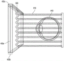
Fig. 4 schematically illustrates an example of a waveguide stack for outputting image information to a user.
Fig. 5 shows an exemplary exit beam that may be output by a waveguide.
FIG. 6 is a schematic diagram showing an optical system including a waveguide device, an optical coupler subsystem for optically coupling light to or from the waveguide device, and a control subsystem for producing a multi-focal volumetric display, image or light field.
Fig. 7 is a block diagram of an example of a wearable system.
FIG. 8 is a process flow diagram of an example of a method of rendering virtual content related to an identified object.
Fig. 9 is a block diagram of another example of a wearable system.
Fig. 10 is a process flow diagram of an example of a method for determining user input for a wearable system.
FIG. 11 is a process flow diagram of an example of a method for interacting with a virtual user interface.
FIG. 12A illustrates an example of a cone projection with a non-negligible aperture.
Fig. 12B and 12C are examples of selecting a virtual object using cone projection with different dynamically adjusted apertures.
12D, 12E, 12F, and 12G depict examples of dynamically adjusting the aperture based on object density.
13, 14, and 15 are flow diagrams of example processes for selecting interactable objects using cone projection with dynamically adjustable apertures.
FIG. 16 schematically illustrates an example of moving a virtual object using a user input device.
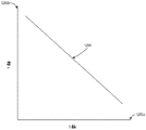
Fig. 17 schematically illustrates an example of the change of the multiplier with distance.
FIG. 18 illustrates a flow chart of an example process for moving a virtual object in response to movement of a user input device.
Throughout the drawings, reference numerals may be reused to indicate correspondence between referenced elements. The drawings are provided to illustrate exemplary embodiments described herein and are not intended to limit the scope of the present disclosure.
Detailed Description
SUMMARY
The wearable system may be configured to display virtual content in an AR/VR/MR environment. The wearable system may allow a user to interact with physical or virtual objects in the user's environment. The user may interact with the object, for example, by selecting and moving the object, using gestures, or by actuating (activate) a user input device. For example, the user may move the user input device a certain distance, and the virtual object will follow the user input device and move the same amount of distance. Similarly, the wearable system may use cone projection to allow the user to select or target a virtual object through a gesture. As the user moves his head, the wearable system may aim and select different virtual objects in the user's field of view accordingly.
These methods can cause user fatigue if the objects are relatively far apart. This is because the user also needs to move the user input device a large distance or increase the amount of body movement (e.g., increase the amount of arm or head movement) a large distance in order to move the virtual object to a desired location or to reach a desired object. In addition, accurately positioning an object at a distance can be challenging, as small amounts of adjustment may be difficult to see in remote locations. On the other hand, as the objects get closer together, the user may prefer a more accurate positioning in order to accurately interact with the desired object.
To reduce user fatigue and provide dynamic user interaction with the wearable system, the wearable system may automatically adjust user interface operations based on the contextual information.
As an example of providing dynamic user interaction based on contextual information, the wearable system may automatically update the aperture of the cone in the cone projection based on contextual factors. For example, if the user turns her head in a direction having a high density of objects, the wearable system may automatically reduce the cone aperture so that there are fewer virtual selectable objects within the cone. Similarly, if the user turns her head in a direction with a low density of objects, the wearable system may automatically increase the cone aperture to include more objects within the cone or reduce the amount of movement necessary to overlap the cone with the virtual object.
As another example, the wearable system may provide a multiplier that may translate the amount of movement of the user input device (and/or the movement of the user) into a greater amount of movement of the virtual object. As a result, when the object is located far away, the user does not have to physically move a large distance to move the virtual object to the desired location. However, when the virtual object is close to the user (e.g., within a hand reach of the user), the multiplier may be set to 1. Thus, the wearable system may provide a one-to-one manipulation between the user movement and the movement of the virtual object. This may allow a user to interact with nearby virtual objects with increased accuracy. Examples of user interactions based on contextual information are described in detail below.
Examples of 3D displays for wearable systems
Wearable systems, also referred to herein as Augmented Reality (AR) systems, may be configured to present 2D or 3D virtual images to a user. The image may be a still image, a video frame or video, a combination of the above, and the like. The wearable system may include a wearable device that may present VR, AR, or MR environments, alone or in combination, for user interaction. The wearable device may be a Head Mounted Device (HMD).
FIG. 1 depicts an illustration of a mixed reality scene with certain virtual reality objects viewed by a person and certain physical objects. In fig. 1, an MR scene 100 is depicted, where a user of MR technology sees a real world park-like setting 110 featuring people, trees, buildings in the background, and a concrete platform 120. In addition to these items, the user of MR technology also perceives that he "sees" a robotic statue 130 standing on the real world platform 120, and a cartoon-style avatar character 140 that looks like a dance of a bumblebee's avatar, although these elements do not exist in the real world.
In order for a 3D display to produce a realistic depth perception, and more particularly a simulated surface depth perception, it may be desirable for each point in the field of view of the display to produce an accommodation response (apparent response) corresponding to its virtual depth. If the accommodation response to a displayed point does not correspond to the virtual depth of the point (as determined by the binocular depth cues for convergence and stereo vision), the human eye may experience accommodation conflicts, resulting in unstable imaging, harmful ocular tension, headaches, and an almost complete lack of surface depth without accommodation information.
The VR, AR, and MR experiences may be provided by a display system having a display in which images corresponding to multiple depth planes are provided to a viewer. The images may be different for each depth plane (e.g., providing a slightly different rendering of a scene or object) and may be focused individually by the eyes of the viewer to facilitate eye-based adjustment that is required to focus different image features of a scene located on different depth planes or to provide depth cues to the user based on observing that different image features on different depth planes are out of focus. As discussed elsewhere herein, such depth cues provide reliable depth perception.
Fig. 2 illustrates an example of a wearable system 200. Wearable system 200 includes a display 220 and various mechanical and electronic modules and systems that support the functionality of display 220. The display 220 may be coupled to a frame 230 that may be worn by a user, wearer, or viewer 210. The display 220 may be positioned in front of the eyes of the user 210. The display 220 may present AR/VR/MR content to the user. The display 220 may include a Head Mounted Display (HMD) worn on the head of the user. In some embodiments, speaker 240 is coupled to frame 230 and positioned near the ear canal of the user (in some embodiments, another speaker (not shown) may be positioned near the other ear canal of the user to provide stereo/shapeable sound control).
The wearable system 200 may include an outward facing imaging system 464 (shown in fig. 4) that views the world in the user's surroundings. Wearable system 200 may further include an inward facing imaging system 462 (shown in fig. 4) that may track the user's eye movements. The inward facing imaging system may track the motion of one eye or both eyes. An inward-facing imaging system 462 may be attached to frame 230 and may be in electrical communication with processing module 260 or 270, and processing module 260 or 270 may process image information acquired by the inward-facing imaging system to determine, for example, a pupil diameter or orientation, an eye movement, or an eye pose of the eye of user 210.
As an example, wearable system 200 may use outward facing imaging system 464 or inward facing imaging system 462 to acquire images of the user gesture. The image may be a still image, a video frame or video, a combination of the above, and the like.
The display 220 may be operatively coupled 250 to the local data processing module 260, for example, by a wired lead or wireless connection, and the local data processing module 260 may be mounted in various configurations, such as fixedly attached to the frame 230, fixedly attached to a helmet or hat worn by the user, embedded in headphones, or otherwise removably attached to the user 210 (e.g., in a backpack configuration, in a belt-coupled configuration).
The local processing and data module 260 may include a hardware processor and digital memory, such as non-volatile memory (e.g., flash memory), both of which may be used for processing, caching, and storage of auxiliary data. The data may include the following: a) data captured from sensors (which may, for example, be operatively coupled to the frame 230 or otherwise attached to the user 210), such as an image capture device (e.g., a camera in an inward facing imaging system or a camera in an outward facing imaging system), a microphone, an Inertial Measurement Unit (IMU), an accelerometer, a compass, a Global Positioning System (GPS) unit, a radio, or a gyroscope; or b) data acquired or processed using remote processing module 270 or remote data repository 280, perhaps communicated to display 220 after such processing or retrieval. Local processing and data module 260 may be operatively coupled to remote processing module 270 or remote data repository 280 by communication links 262 or 264 (such as via wired or wireless communication links) so that these remote modules are available as resources to local processing and data module 260. Additionally, remote processing module 280 and remote data repository 280 may be operatively coupled to each other.
In some embodiments, remote processing module 270 may include one or more processors configured to analyze and process data and/or image information. In some embodiments, remote data repository 280 may include a digital data storage facility, which may be available in a "cloud" resource configuration over the internet or other network configuration. In some embodiments, all data is stored in the local processing and data module and all calculations are performed, allowing for fully autonomous use from the remote module.
The human visual system is complex and it is challenging to provide a realistic perception of depth. Without being limited by theory, it is believed that a viewer of an object may perceive the object as "three-dimensional" due to a combination of vergence and accommodation. Vergence movement of the two eyes relative to each other (i.e., rolling movement of the pupils toward or away from each other to converge the line of sight of the eyes to fixate on an object) is closely related to the focusing (or "accommodation") of the eye's lens. Under normal circumstances, changing the focus of the eye lens or adjusting the eye to change the focus from one object to another object at a different distance will automatically result in a change in the match of vergences to the same distance under a relationship known as "accommodation-vergence reflex". Also, under normal circumstances, a change in vergence will cause a matching change in accommodation. A display system that provides a better match between accommodation and vergence may result in a more realistic and comfortable three-dimensional image simulation.
FIG. 3 illustrates aspects of a method of simulating a three-dimensional image using multiple depth planes. Referring to fig. 3, objects at different distances from the eye 302 and the eye 304 on the z-axis are accommodated by the eye 302 and the eye 304 such that the objects are in focus. Eyes 302 and 304 assume a particular state of accommodation such that objects at different distances along the z-axis are brought into focus. Thus, it can be said that a particular state of accommodation is associated with a particular one of the depth planes 306 having an associated focal length such that an object or portion of an object in the depth plane is focused when the eye is in the state of accommodation of the particular depth plane. In some embodiments, a three-dimensional image may be simulated by providing a different rendering of the image for each of the eyes 302 and 304, and also by providing a different rendering of the image corresponding to each of the depth planes. Although shown as separate for clarity of illustration, it is understood that the fields of view of eye 302 and eye 304 may overlap, for example, as the distance along the z-axis increases. Additionally, while shown as flat for ease of illustration, it is understood that the profile of the depth plane may be curved in physical space such that all features in the depth plane are in focus with the eye under a particular state of accommodation. Without being limited by theory, it is believed that the human eye can generally interpret a limited number of depth planes to provide depth perception. Thus, by providing the eye with a different presentation of the image corresponding to each of these limited number of depth planes, a highly reliable simulation of the perceived depth may be achieved.
Waveguide stack assembly
Fig. 4 illustrates an example of a waveguide stack for outputting image information to a user. The wearable system 400 includes a waveguide stack or stacked waveguide assembly 480 that can be used to provide three-dimensional perception to the eye/brain using a plurality of waveguides 432b, 434b, 436b, 438b, 4400 b. In some embodiments, wearable system 400 may correspond to wearable system 200 of fig. 2, with fig. 4 schematically illustrating some portions of wearable system 200 in more detail. For example, in some embodiments, the waveguide assembly 480 may be integrated into the display 220 of fig. 2.
With continued reference to fig. 4, the waveguide assembly 480 may further include a plurality of features 458, 456, 454, 452 located between the waveguides. In some embodiments, the features 458, 456, 454, 452 may be lenses. In other embodiments, the features 458, 456, 454, 452 may not be lenses. Instead, they may simply be spacers (e.g., cladding and/or structures for forming air gaps).
The waveguides 432b, 434b, 436b, 438b, 440b or the plurality of lenses 458, 456, 454, 452 may be configured to transmit image information to the eye at various levels of wavefront curvature or light divergence. Each waveguide level may be associated with a particular depth plane and may be configured to output image information corresponding to that depth plane. The image injection devices 420, 422, 424, 426, 428 may be used to inject image information into waveguides 440b, 438b, 436b, 434b, 432b, each of which may be configured to distribute incident light through each respective waveguide for output toward the eye 410. Light exits the output surfaces of the image injection devices 420, 422, 424, 426, 428 and is injected into the respective input edges of the waveguides 440b, 438b, 436b, 434b, 432 b. In some embodiments, a single beam (e.g., a collimated beam) may be injected into each waveguide to output an entire field of cloned collimated beams that are directed toward the eye 410 at a particular angle (and amount of divergence) corresponding to the depth plane associated with the particular waveguide.
In some embodiments, the image injection devices 420, 422, 424, 426, 428 are discrete displays, each display producing image information for injection into a respective waveguide 440b, 438b, 436b, 434b, 432b, respectively. In some other embodiments, the image injection devices 420, 422, 424, 426, 428 are outputs of a single multiplexed display that can pipe image information to each of the image injection devices 420, 422, 424, 426, 428, such as via one or more light pipes (e.g., fiber optic cables).
The controller 460 controls the operation of the stacked waveguide assembly 480 and the image injection devices 420, 422, 424, 426, 428. Controller 460 includes programming (e.g., instructions in a non-transitory computer readable medium) that adjusts the timing and provision of image information to waveguides 440b, 438b, 436b, 434b, 432 b. In some embodiments, controller 460 may be a single unitary device or a distributed system connected by a wired or wireless communication channel. In some embodiments, the controller 460 may be part of the processing module 260 or 270 (shown in FIG. 2).
The waveguides 440b, 438b, 436b, 434b, 432b may be configured to propagate light within each respective waveguide by Total Internal Reflection (TIR). The waveguides 440b, 438b, 436b, 434b, 432b may each be planar or have other shapes (e.g., curved), with top and bottom major surfaces and edges extending between the top and bottom major surfaces. In the illustrated configuration, the waveguides 440b, 438b, 436b, 434b, 432b may each include light extraction optics 440a, 438a, 436a, 434a, 432a configured to extract light out of the waveguides by redirecting light propagating within each respective waveguide to output image information to the eye 410. The extracted light may also be referred to as outcoupled light and the light extracting optical element may also be referred to as an outcoupled optical element. The extracted light beam is output by the waveguide at a location where light propagating in the waveguide strikes the light redirecting element. The light extraction optical elements (440a, 438a, 436a, 434a, 432a) may be, for example, reflective or diffractive optical features. Although illustrated as being disposed at the bottom major surface of the waveguides 440b, 438b, 436b, 434b, 432b for ease of description and clarity of drawing, in some embodiments the light extraction optical elements 440a, 438a, 436a, 434a, 432a may be disposed at the top or bottom major surface or may be disposed directly in the volume of the waveguides 440b, 438b, 436b, 434b, 432 b. In some embodiments, the light extraction optical elements 440a, 438a, 436a, 434a, 432a may be formed in a layer of material attached to a transparent substrate to form waveguides 440b, 438b, 436b, 434b, 432 b. In some other embodiments, the waveguides 440b, 438b, 436b, 434b, 432b may be a single piece of material, and the light extraction optical elements 440a, 438a, 436a, 434a, 432a may be formed on a surface of that piece of material or in the interior of that piece of material.
With continued reference to fig. 4, as discussed herein, each waveguide 440b, 438b, 436b, 434b, 432b is configured to output light to form an image corresponding to a particular depth plane. For example, the waveguide 432b closest to the eye may be configured to deliver collimated light to the eye 410 as injected into such waveguide 432 b. The collimated light may represent an optically infinite focal plane. The next upper row waveguide 434b can be configured to emit collimated light that is transmitted through the first lens 452 (e.g., a negative lens) before it can reach the eye 410. The first lens 452 can be configured to produce a slightly convex wavefront curvature such that the eye/brain interprets light from the next upward waveguide 434b as coming from a first focal plane that is closer inward from optical infinity to the eye 410. Similarly, the third upstream waveguide 436b transmits the output light through the first lens 452 and the second lens 454 before reaching the eye 410. The combined optical power of the first lens 452 and the second lens 454 can be configured to produce another increment of wavefront curvature so that the eye/brain interprets light from the third waveguide 436b as coming from a second focal plane that is further inward from optical infinity to the person than light from the next upward waveguide 434 b.
The other waveguide layers (e.g., waveguides 438b, 440b) and lenses (e.g., lenses 456, 458) are similarly configured, with the highest waveguide 440b in the stack sending its output through all of the lenses between it and the eye for representing the total (aggregate) power closest to the person's focal plane. To compensate for the stack of lenses 458, 456, 454, 452 when viewing/interpreting light from the world 470 on the other side of the stacked waveguide assembly 480, a compensating lens layer 430 may be disposed at the top of the stack to compensate for the total power of the underlying lens stack 458, 456, 454, 452. This configuration provides as many sensing focal planes as there are waveguide/lens pairs available. The focusing aspects of the light extraction optics and lenses of the waveguide may be static (e.g., not dynamic or electrically active). In some alternative embodiments, either or both may be dynamic using electrically active features.
With continued reference to fig. 4, the light extraction optical elements 440a, 438a, 436a, 434a, 432a may be configured to redirect light out of their respective waveguides and output the light with an appropriate amount of divergence or degree of collimation for the particular depth plane associated with the waveguide. As a result, waveguides with different associated depth planes may have different configurations of light extraction optical elements that output light with different amounts of divergence depending on the associated depth plane. In some embodiments, as discussed herein, the light extraction optical elements 440a, 438a, 436a, 434a, 432a may be volumes or surface features that may be configured to output light at a particular angle. For example, the light extraction optical elements 440a, 438a, 436a, 434a, 432a may be volume holograms, surface holograms, and/or diffraction gratings. Light extraction optical elements such as diffraction gratings are described in U.S. patent publication No.2015/0178939, published on 25/6/2015, which is incorporated herein by reference in its entirety.
In some embodiments, the light extraction optical elements 440a, 438a, 436a, 434a, 432a are diffractive features or "diffractive optical elements" (also referred to herein as "DOEs") that form a diffraction pattern. Preferably, the DOE has a relatively low diffraction efficiency, such that only a portion of the beam is deflected by each intersection of the DOE towards the eye 410, while the remainder continues to move through the waveguide via total internal reflection. The light carrying the image information can thus be split into a plurality of related exit beams that exit the waveguide at a plurality of locations, and the result is a fairly uniform pattern of exit emissions towards the eye 304 for that particular collimated beam bouncing within the waveguide.
In some embodiments, one or more DOEs may be switchable between an "on" state in which they actively diffract and an "off" state in which they do not significantly diffract. For example, a switchable DOE may comprise a polymer dispersed liquid crystal layer, wherein the droplets comprise a diffraction pattern in the matrix medium, and the refractive index of the droplets may be switched to substantially match the refractive index of the matrix material (in which case the pattern DOEs not significantly diffract incident light), or the droplets may be switched to a refractive index that DOEs not match the refractive index of the matrix medium (in which case the pattern actively diffracts incident light).
In some embodiments, the number and distribution of depth planes or depth of field may be dynamically changed based on the pupil size or orientation of the viewer's eyes. The depth of field may vary inversely with the pupil size of the viewer. Thus, as the pupil size of the viewer's eye decreases, the depth of field increases, such that a plane that is not discernable due to its position beyond the depth of focus of the eye may become discernable, and appear to be more focused as the pupil size decreases, commensurate with the increase in depth of field. Likewise, the number of spaced apart depth planes for presenting different images to a viewer may decrease as the pupil size decreases. For example, a viewer may not be able to clearly perceive details of both the first depth plane and the second depth plane at one pupil size without adjusting the accommodation of the eye from one depth plane to another. However, the two depth planes may be sufficiently focused at the same time for a user at another pupil size without changing the adjustment.
In some embodiments, the display system may change the number of waveguides receiving image information based on a determination of pupil size or orientation, or upon receiving an electrical signal indicative of a particular pupil size or orientation. For example, if the user's eye is unable to distinguish between two depth planes associated with two waveguides, controller 460 may be configured or programmed to stop providing image information to one of the waveguides. Advantageously, this may reduce the processing burden on the system, thereby increasing the responsiveness of the system. In embodiments in which the DOE for a waveguide is switchable between on and off states, the DOE may be switched to the off state when the waveguide DOEs receive image information.
In some embodiments, it may be desirable to have the outgoing beam satisfy a condition that the diameter is smaller than the diameter of the viewer's eye. However, meeting such conditions can be challenging given the variability of the pupil size of the viewer. In some embodiments, this condition is satisfied over a wide range of pupil sizes by varying the size of the emergent beam in response to a determination of the pupil size of the viewer. For example, as the pupil size decreases, the size of the exiting light beam may also decrease. In some embodiments, an iris diaphragm may be used to vary the outgoing beam size.
The wearable system 400 may include an outward facing imaging system 464 (e.g., a digital camera) that images a portion of the world 470. This portion of the world 470 may be referred to as the field of view (FOV), and the imaging system 464 is sometimes referred to as a FOV camera. The entire area available FOR viewing or imaging by a viewer may be referred to as the field of view (FOR). Because the wearer can move his body, head, or eyes to perceive substantially any direction in space, the FOR can include 4 pi steradians around the solid angle of wearable system 400. In other cases, the wearer's motion may be more restricted, and accordingly, the wearer's FOR may subtend a smaller solid angle. Images obtained from the outward facing imaging system 464 may be used to track gestures made by the user (e.g., hand or finger gestures), detect objects in the world 470 in front of the user, and so forth.
The wearable system 400 may also include an inward facing imaging system 466 (e.g., a digital camera) that observes user motion, such as eye motion and facial motion. The inward facing imaging system 466 may be used to capture images of the eye 410 to determine the size and/or orientation of the pupil of the eye 304. The inward facing imaging system 466 may be used to obtain images for determining the direction in which the user is looking (e.g., eye gestures) or for biometric recognition of the user (e.g., via iris recognition). In some embodiments, at least one camera may be utilized for each eye to independently determine the pupil size or eye pose of each eye separately, thereby allowing image information to be presented to each eye to dynamically fit the eye. In some other embodiments, the pupil diameter or orientation of only a single eye 410 (e.g., using only a single camera per pair of eyes) is determined and assumed to be similar for both eyes of the user. The images obtained by the inward facing imaging system 466 may be analyzed to determine the user's eye posture or mood, which may be used by the wearable system 400 to decide which audio or visual content should be presented to the user. Wearable system 400 may also use sensors such as IMUs, accelerometers, gyroscopes, etc. to determine head pose (e.g., head position or head orientation).
Fig. 5 shows an example of an outgoing light beam output by a waveguide. One waveguide is shown, but it should be understood that other waveguides in the waveguide assembly 480 may function similarly, where the waveguide assembly 480 includes a plurality of waveguides. Light 520 is injected into waveguide 432b at input edge 432c of waveguide 432b and propagates within waveguide 432b by TIR. At the point where light 520 impinges on DOE 432a, a portion of the light exits the waveguide as exit beam 510. The exit light beam 510 is shown as being substantially parallel, but depending on the depth plane associated with the waveguide 432b, the exit light beam 510 may also be redirected at an angle (e.g., to form a diverging exit light beam) to propagate to the eye 410. It should be understood that the substantially parallel exit beams may be indicative of a waveguide having light extraction optics that couple out light to form an image that appears to be disposed on a depth plane at a large distance (e.g., optical infinity) from the eye 410. Other waveguides or other groups of light extraction optical elements may output a more divergent exit beam pattern, which would require eye 410 to adjust to a closer distance to focus it on the retina and would be interpreted by the brain as light from a distance closer to eye 410 than optical infinity.
FIG. 6 is a schematic diagram showing an optical system including a waveguide device, an optical coupler subsystem to optically couple light to or from the waveguide device, and a control subsystem for generating a multi-focal stereoscopic display, image, or light field. The optical system may include a waveguide device, an optical coupler subsystem to optically couple light to or from the waveguide device, and a control subsystem. The optical system may be used to generate a multi-focal stereo, image or light field. The optical system may include one or more planar bus waveguides 632a (only one shown in fig. 6) and one or more DOEs 632b associated with each of at least some of the bus waveguides 632 a. The planar waveguide 632b may be similar to the waveguides 432b, 434b, 436b, 438b, 440b discussed with reference to fig. 4. The optical system may use a distributed waveguide device to relay light along a first axis (the vertical or Y-axis in the view of fig. 6) and expand the effective exit pupil of the light along the first axis (e.g., the Y-axis). The distributed waveguide apparatus may, for example, include a distributed planar waveguide 622b and at least one DOE 622a (shown by dashed double-dotted lines) associated with the distributed planar waveguide 622 b. The distribution planar waveguide 622b may be similar or identical to, but have a different orientation than, the main planar waveguide 632b in at least some respects. Similarly, at least one DOE 622a may be similar or identical in at least some respects to DOE 632 a. For example, the distribution planar waveguide 622b or DOE 622a may be composed of the same material as the main planar waveguide 632b or DOE 632a, respectively. The embodiment of the optical display system 600 shown in fig. 6 may be integrated into the wearable display system 200 shown in fig. 2.
The relayed and exit pupil expanded light can be optically coupled from the distribution waveguide arrangement into one or more of the main planar waveguides 632 b. The primary planar waveguide 632b may relay light along a second axis (e.g., the horizontal or X-axis in the view of fig. 6), which is preferably orthogonal to the first axis. Notably, the second axis may be a non-orthogonal axis to the first axis. The main planar waveguide 632b expands the effective exit pupil of light along this second axis (e.g., the X-axis). For example, the distribution planar waveguide 622b can relay and expand light along the vertical or Y-axis and deliver the light to the main planar waveguide 632b, which can relay and expand light along the horizontal or X-axis.
The optical system may include one or more colored light sources (e.g., red, green, and blue lasers) 610, which may be optically coupled into the proximal end of a single mode fiber 640. The distal end of the optical fiber 640 may be passed through or received by a hollow tube 642 of piezoelectric material. The distal end protrudes from the tube 642 as an unsecured flexible cantilever 644. The piezoelectric tubes 642 may be associated with four quadrant electrodes (not shown). For example, the electrodes may be plated on the outside, outer surface, or periphery or outer diameter of the tube 642. A core electrode (not shown) may also be located in the core, center, inner periphery, or inner diameter of tube 642.
Drive electronics 650, for example, electrically coupled via leads 660, drive the opposing pairs of electrodes to independently bend the piezoelectric tube 642 in two axes. The protruding distal tip of the optical fiber 644 has a mechanical resonance mode. The frequency of resonance may depend on the diameter, length, and material characteristics of the optical fiber 644. By vibrating the piezoelectric tube 642 near the first mechanical resonance mode of the fiber cantilever 644, the fiber cantilever 644 can be made to vibrate and can sweep large deflections.
The tip of the fiber optic cantilever 644 is scanned bi-axially throughout the area of the two-dimensional (2-D) scan by exciting resonances in both axes. By modulating the intensity of one or more light sources 610 in synchronization with the scanning of the fiber optic cantilever 644, the light exiting the fiber optic cantilever 644 may form an image. A description of such an arrangement is provided in U.S. patent publication No.2014/0003762, which is incorporated herein by reference in its entirety.
Components of the optical coupler subsystem may collimate the light exiting the scanning fiber cantilever 644. The collimated light may be reflected by a mirror 648 into a narrow distribution planar waveguide 622b containing at least one Diffractive Optical Element (DOE)622 a. The collimated light can propagate vertically (relative to the view of figure 6) along the distribution planar waveguide 622b by TIR and in so doing repeatedly intersect with the DOE 622 a. The DOE 622a preferably has low diffraction efficiency. This may result in a portion (e.g., 10%) of the light being diffracted towards the edge of the larger principal planar waveguide 632b at each intersection with the DOE 622a, and a portion of the light continuing down the length of the distribution planar waveguide 622b on its original trajectory by TIR.
At each intersection with DOE 622a, the additional light may be diffracted towards the entrance of the main waveguide 632 b. By dividing the incident light into a plurality of outcoupling groups, the exit pupil of the light can be vertically expanded by the DOE 4 in the distribution plane waveguide 622 b. The vertically expanded light coupled out of the distribution planar waveguide 622b can enter the edge of the main planar waveguide 632 b.
Light entering the main waveguide 632b may propagate horizontally (relative to the view of fig. 6) along the main waveguide 632b via TIR. As light propagates horizontally by TIR along at least a portion of the length of the primary waveguide 632b, the light intersects the DOE 632a at multiple points. The DOE 632a may advantageously be designed or constructed to have a phase profile that is the sum of a linear diffraction pattern and a radially symmetric diffraction pattern to produce deflection and focusing of light. The DOE 632a may advantageously have a low diffraction efficiency (e.g., 10%) such that only a portion of the light of the beam is deflected toward the eye of view at each intersection of the DOE 632a, while the rest of the light continues to propagate through the waveguide 632b via TIR.
At each intersection between the propagating light and the DOE 632a, a portion of the light is diffracted towards the adjacent facet of the primary waveguide 632b, allowing the light to escape TIR and exit the facet of the primary waveguide 632 b. In some embodiments, the radially symmetric diffraction pattern of the DOE 632a additionally imparts a level of focus to the diffracted light, both shaping the optical wavefront of the individual beams (e.g., imparting curvature) and steering the beams at an angle that matches the designed level of focus.
Thus, these different paths may couple light out of the main planar waveguide 632b by multiple DOEs 632a at different angles, focus levels, and/or creating different fill patterns at the exit pupil. Different fill patterns at the exit pupil may advantageously be used to create a light field display with multiple depth planes. Each layer in the waveguide assembly or a set of layers (e.g., 3 layers) in the stack may be used to produce a respective color (e.g., red, blue, green). Thus, for example, a first set of three adjacent layers may be employed to produce red, blue, and green light, respectively, at a first focal depth. A second set of three adjacent layers may be used to produce red, blue and green light, respectively, at a second focal depth. Multiple groups can be employed to generate a full 3D or 4D color image light field with various focal depths.
Other parts of wearable system
In many embodiments, the wearable system may include other components in addition to or in place of the components of the wearable system described above. The wearable system may include, for example, one or more haptic devices or components. Haptic devices or components may be used to provide haptic sensations to a user. For example, a haptic device or component may provide pressure or texture haptics when touching virtual content (e.g., virtual objects, virtual tools, other virtual constructs). Haptic sensations can replicate the sensation of a physical object represented by a virtual object, or can replicate the sensation of a desired object or character (e.g., a dragon) represented by virtual content. In some embodiments, the haptic device or component may be worn by a user (e.g., a glove wearable by the user). In some embodiments, the haptic device or component may be held by a user.
The wearable system may include, for example, one or more physical objects that may be manipulated by a user to allow input or interaction with the wearable system. These physical objects may be referred to herein as totems. Some totems may take the form of inanimate objects such as, for example, metal or plastic blocks, walls, surfaces of tables. In some embodiments, the totem may not actually have any physical input structures (e.g., keys, triggers, joysticks, trackballs, rocker switches). Instead, the totem may simply provide a physical surface, and the wearable system may present a user interface to appear to the user to be on one or more surfaces of the totem. For example, the wearable system may make it appear that an image of the computer keyboard and touch pad reside on one or more surfaces of the totem. For example, the wearable system may make a virtual computer keyboard and virtual touchpad appear on the surface of a thin rectangular plate of aluminum, which is a totem. The rectangular plate itself does not have any physical keys or touch pads or sensors. However, the wearable system may detect user manipulation or interaction or touching the rectangular pad as a selection or input via a virtual keyboard or virtual trackpad. User input device 466 (shown in fig. 4) may be a totem embodiment, which may include a touch pad, trigger, joystick, trackball, joystick or virtual switch, mouse, keyboard, multiple degree of freedom controller, or another physical input device. The user may use totems, alone or in combination with gestures, to interact with a wearable system or other users.
Examples of haptic devices and totems that may be used in the wearable devices, HMDs, and display systems of the present disclosure are described in U.S. patent publication No.2015/0016777, which is incorporated herein by reference in its entirety.
Wearable systemEnvironment and interface examples
Wearable systems may employ various mapping-related techniques in order to achieve a high depth of field in the rendered light field. When drawing a virtual world, it is advantageous to know all the features and points in the real world to accurately depict virtual objects related to the real world. To do so, FOV images captured from a user of the wearable system may be added to the world model by including new pictures conveying information about various points and features of the real world. For example, the wearable system may collect a set of map points (such as 2D points or 3D points) and find a new map point (map point) to present a more accurate version of the world model. The world model of the first user may be communicated to the second user (e.g., over a network such as a cloud network) so that the second user may experience the world surrounding the first user.
Fig. 7 is a block diagram of an example of an MR environment 700. The MR environment 700 may be configured to receive input (e.g., visual input 702 from a user's wearable system, stationary input 704 such as a room camera, sensor input 706 from various sensors, user input from user input devices 466, gestures, totems, eye tracking, etc.) from one or more user wearable systems (e.g., wearable system 200 or display system 220) or fixed room systems (e.g., an indoor camera, etc.). The wearable system may use various sensors (e.g., accelerometers, gyroscopes, temperature sensors, movement sensors, depth sensors, GPS sensors, inward facing imaging systems, outward facing imaging systems, etc.) to determine the location and various other attributes of the user's environment. This information may be further supplemented with information from stationary cameras in the room, which may provide images or various cues from different viewpoints. Image data acquired by a camera (such as a room camera and/or a camera of an outward facing imaging system) may be reduced to a set of map points.
One or more object identifiers 708 may crawl (crawl through) the received data (e.g., a collection of points) and identify or map points, mark images, and append semantic information to the objects by means of a map database 710. Map database 710 may include various points collected over time and their corresponding objects. The various devices and map databases may be interconnected through a network (e.g., LAN, WAN, etc.) to access the cloud.
Based on this information and the set of points in the map database, object identifiers 708a through 708n may identify objects in the environment. For example, the object identifier may identify a face, a person, a window, a wall, a user input device, a television, other objects in the user's environment, and so forth. One or more object identifiers may be dedicated to objects having particular characteristics. For example, object identifier 708a may be used to identify a face, while another object identifier may be used to identify a totem.
Object recognition may be performed using various computer vision techniques. For example, the wearable system may analyze images acquired by the outward facing imaging system 464 (as shown in fig. 4) to perform scene reconstruction, event detection, video tracking, object recognition, object pose estimation, learning, indexing, motion estimation, image restoration, or the like. One or more computer vision algorithms may be used to perform these tasks. Non-limiting examples of computer vision algorithms include: scale Invariant Feature Transform (SIFT), Speeded Up Robust Features (SURF), oriented FAST and rotated BRIEF (ORB), binary robust invariant extensible key points (BRISK), FAST retinal key points (FREAK), Viola-Jones algorithm, eigenface method, Lucas-Kanade algorithm, Horn-Schunk algorithm, mean-shift (Mean-shift) algorithms, visual synchronous localization and mapping (vSLAM) techniques, sequence bayesian estimators (e.g., kalman filters, extended kalman filters, etc.), bundle adjustment (bundle adjustment), adaptive thresholding (and other thresholding techniques), Iterative Closest Point (ICP), semi-global matching (SGM), semi-global block matching (SGBM), feature point histograms, various machine learning algorithms (e.g., support vector machines, k-nearest neighbor algorithms, naive bayes, neural networks (including convolutional or deep neural networks) or other supervised/unsupervised models, etc.), and the like.
Additionally or alternatively, object recognition may be performed by various machine learning algorithms. Once trained, the machine learning algorithm may be stored by the HMD. Some examples of machine learning algorithms may include supervised or unsupervised machine learning algorithms, including regression algorithms (e.g., ordinary least squares regression), instance-based algorithms (e.g., learning vector quantization), decision tree algorithms (e.g., classification and regression trees), bayesian algorithms (e.g., na iotave bayes), clustering algorithms (e.g., k-means clustering), association rule learning algorithms (e.g., a priori), artificial neural network algorithms (e.g., perceptron), deep learning algorithms (e.g., deep boltzmann machine or deep neural network), dimension reduction algorithms (e.g., principal component analysis), ensemble algorithms (e.g., stack generalization), and/or other machine learning algorithms. In some embodiments, individual models may be customized for individual data sets. For example, the wearable device may generate or store a base model. The base model may be used as a starting point for generating additional models that are specific to the type of data (e.g., a particular user in a telepresence session), the data set (e.g., additional image sets obtained from the user in the telepresence session), the condition, or other changes. In some embodiments, the wearable HMD may be configured to utilize a variety of techniques to generate a model for analyzing the aggregated data. Other techniques may include using predefined thresholds or data values.
Based on this information and the set of points in the map database, the object identifiers 708a-708n may identify objects and supplement the objects with semantic information to give the objects life. For example, if the object identifier identifies a set of points as a door, the system may append some semantic information (e.g., the door has a hinge and has 90 degrees of movement around the hinge). If the object identifier identifies a set of points as mirrors, the system may append semantic information that: the mirror has a reflective surface that can reflect an image of an object in the room. Over time, map databases grow as the system (which may reside locally or be accessible through a wireless network) accumulates more data from the world. Once the object is identified, this information may be sent to one or more wearable systems. For example, MR environment 700 may include information about a scene occurring in california. The environment 700 may be sent to one or more users of new york. Based on data received from the FOV camera and other inputs, the object identifier and other software components may map points collected from various images, identify objects, etc., so that the scene may be accurately "passed on" to a second user, possibly in a different part of the world. The environment 700 may also use a topology map for localization purposes.
FIG. 8 is a process flow diagram of an example of a method 800 of presenting virtual content related to an identified object. Method 800 describes how to present a virtual scene to a user of a wearable system. The user may be geographically distant from the scene. For example, a user may be in new york, but may want to view a scene that is currently occurring in california, or may want to walk with friends that live in california.
At block 810, the wearable system may receive input from the user and other users regarding the user's environment. This can be achieved by various input devices and knowledge already in the map database. At block 810, the user's FOV camera, sensor, GPS, eye tracking, etc. communicates information to the system. At block 820, the system may determine sparse points based on the information. Sparse points may be used to determine pose data (e.g., head pose, eye pose, body pose, or hand gesture) that may be used to display and understand the orientation and position of various objects in the user's surroundings. At block 830, the object identifiers 708a-708n may crawl through these collected points and identify one or more objects using the map database. This information may then be communicated to the user's personal wearable system at block 840, and the desired virtual scene may be displayed to the user accordingly at block 850. For example, a desired virtual scene (e.g., a user located at CA) may be displayed in an appropriate orientation, position, etc., relative to various objects and other environments of the user in New York.
Fig. 9 is a block diagram of another example of a wearable system. In this example, wearable system 900 includes a map, which may include map data of the world. The map may reside partially locally to the wearable system, and may reside partially in a network storage location accessible through a wired or wireless network (e.g., in a cloud system). Gesture processing 910 may be executed on a wearable computing architecture (e.g., processing module 260 or controller 460) and utilize data from a map to determine a position and orientation of the wearable computing hardware or the user. Gesture data may be calculated from data collected instantaneously as the user is experiencing the system and operating in the world. The data may include images, data from sensors (e.g., inertial measurement units, which typically include accelerometer and gyroscope components), and surface information related to objects in a real or virtual environment.
The sparse point representation may be the output of a simultaneous localization and mapping (SLAM or V-SLAM, meaning a configuration in which the input is image/visual only) process. The system may be configured to not only find the locations of various components in the world, but also find out what the world is made up of. Gestures may be building blocks that achieve many goals, including populating maps and using data from maps.
In one embodiment, the sparse point location itself may not be entirely sufficient, and further information may be needed to produce a multi-focus AR, VR or MR experience. The gap may be at least partially filled with a dense representation of the general reference depth map information. Such information may be calculated according to a process 940 known as Stereo (Stereo), where depth information is determined using techniques such as triangulation or time-of-flight sensing. Image information and an active (active) mode, such as an infrared mode created using an active (active) projector, may be used as inputs to stereo process 940. A large amount of depth map information may be fused together and some of them may be summarized in a surface representation. For example, a mathematically definable surface is an efficient (e.g., relative to a large point cloud) and digestible input for other processing devices such as a game engine. Thus, the outputs of the stereo process (e.g., depth map) 940 may be combined in the fusion process 930. A gesture may also be an input to the fusion process 930, and the output of the fusion 930 becomes an input to the fill (output) map process 920. The sub-surfaces may be connected to each other (e.g. in a topographical map) to form a larger surface, and the map becomes a large mixture of points and surfaces.
To address various aspects in the mixed reality process 960, various inputs may be used. For example, in the embodiment shown in fig. 9, game parameters may be entered to determine that a user of the system is playing a monster game, where one or more monsters are located at various locations, monsters die or escape under various conditions (e.g., if the user kills a monster), walls or other objects are located at various locations, and so forth. The world map may include information about where these objects are relevant to each other as another valuable input to the mixed reality. Gestures relative to the world also become an input and play a key role for almost any interactive system.
The control or input from the user is another input to the wearable system 900. As described herein, user inputs may include visual inputs, gestures, totems, audio inputs, sensory inputs, and the like. To move around or play a game, for example, the user may need to instruct wearable system 900 as to what he or she wants to do. There are many forms of user control that may be utilized in addition to moving itself in space. In one embodiment, a totem (e.g., user input device) or object such as a toy gun may be held by a user and tracked by the system. The system is preferably configured to know that the user is holding the merchandise and understand what interaction the user is with the merchandise (e.g., if the tote or object is a gun, the system may be configured to know the location and orientation, and whether the user is clicking a trigger or other sensing button or element, such as an IMU, that may be equipped with a sensor, which may help determine what is happening even if such activity is not within the field of view of any camera).
Gesture tracking or recognition may also provide input information. Wearable system 900 may be configured to track and interpret gestures of button presses for gesturing left or right, stopping, grabbing, holding, and the like. For example, in one configuration, a user may want to flip through an email or calendar, or "punch" with others or players in a non-gaming environment. Wearable system 900 may be configured to utilize a minimum amount of gestures, which may or may not be dynamic. For example, the gesture may be a simple static gesture such as opening the watch to stop, pointing with the thumb to indicate good (ok), and pointing with the thumb down to indicate not good; or flip the hand side-to-side or up-and-down to make directional commands.
Eye tracking is another input (e.g., tracking where a user is looking to control display technology to render at a particular depth or range). In one embodiment, the vergence of the eyes may be determined using triangulation, and then accommodation may be determined using a vergence/accommodation model developed for that particular character.
With respect to camera systems, the exemplary wearable system 900 shown in fig. 9 may include three pairs of cameras: a relatively wide FOV or passive SLAM camera pair arranged to the side of the user's face, with a different camera pair positioned in front of the user to handle the stereo imaging process 940 and also to capture gestures and totem/object tracking in front of the user's face. The FOV camera and the camera pair used for stereoscopic processing 940 may be part of an outward facing imaging system 464 (shown in fig. 4). Wearable system 900 may include an eye-tracking camera (which may be part of inward-facing imaging system 462 shown in fig. 4) oriented toward the user's eye in order to triangulate eye vectors and other information. Wearable system 900 may also include one or more textured light projectors (e.g., Infrared (IR) projectors) to inject texture into the scene.
Fig. 10 is a process flow diagram of an example of a method 1000 for determining user input to a wearable system. In this example, the user may interact with the totem. A user may have multiple totems. For example, the user may have designated one totem for a social media application, another totem for playing a game, and so on. At block 1010, the wearable system may detect a movement of the totem. The movement of the totem may be recognized by an outward facing system or may be detected by sensors (e.g., tactile gloves, image sensors, hand tracking devices, eye tracking cameras, head pose sensors, etc.).
At block 1020, based at least in part on the detected gesture, eye pose, head pose, or input through the totem, the wearable system detects the position, orientation, and/or movement of the totem (or the user's eyes or head or gesture) relative to a reference frame (reference frame). The reference frame may be a set of map points based on which the wearable system translates the movement of the totem (or user) into an action or command. At block 1030, the user's interactions with the totem are mapped (map). At block 1040, based on the mapping of the user interaction with respect to the frame of reference 1020, the system determines a user input.
For example, a user may move a totem or physical object back and forth to indicate that a virtual page is flipped and moved to the next page or from one User Interface (UI) display screen to another. As another example, a user may move their head or eyes to view different real or virtual objects in the user's FOR. A particular real or virtual object may be selected as user input if the user gazes at the real or virtual object for longer than a threshold time. In some implementations, the vergence of the user's eyes may be tracked and an accommodation state of the user's eyes may be determined using an accommodation/vergence model, which provides information about the depth plane in which the user is focusing. In some implementations, the wearable system can use ray casting techniques to determine which real or virtual objects are along the direction of the user's head pose or eye pose. In various embodiments, the ray casting technique may include casting a thin pencil ray having a substantially small lateral width or a ray having a large lateral width (e.g., a cone or frustum).
The user interface may be projected by a display system described herein (e.g., display 220 in fig. 2). It may also be displayed using various other technologies, such as one or more projectors. The projector may project an image onto a physical object such as a canvas or a globe. One or more cameras external to or as part of the system may be used (e.g., using an inward facing imaging system 462 or an outward facing imaging system 464) to track interactions with the user interface.
FIG. 11 is a process flow diagram of an example of a method 1100 for interacting with a virtual user interface. Method 1100 may be performed by a wearable system described herein.
At block 1110, the wearable system may identify a particular UI. The type of UI may be predetermined by the user. The wearable system may identify a need to populate a particular UI based on user input (e.g., gestures, visual data, audio data, sensory data, direct commands, etc.). At block 1120, the wearable system may generate data for the virtual UI. For example, data associated with the bounds (define), general structure, shape, etc. of the UI may be generated. Additionally, the wearable system may determine map coordinates of the user's physical location such that the wearable system may display a UI related to the user's physical location. For example, if the UI is body-centered, the wearable system may determine coordinates, head gestures, or eye gestures of the user's body position (physical stance) such that a ring-shaped UI may be displayed around the user, or a planar UI may be displayed on a wall or in front of the user. If the UI is hand-centered, the map coordinates of the user's hand may be determined. These map points may be taken by means of data received by the FOV camera, sensory input or any other type of collected data.
At block 1130, the wearable system may send data from the cloud to the display, or the data may be sent from a local database to the display component. At block 1140, a UI is displayed to the user based on the transmitted data. For example, the light field display may project a virtual UI into one or both eyes of the user. At block 1150, once the virtual UI is created, the wearable system need only wait for commands from the user to generate more virtual content on the virtual UI. For example, the UI may be a body center ring around the user's body. The wearable system may then wait for a command (gesture, head or eye motion, input from a user input device, etc.) and, if it is recognized (block 1160), may display virtual content associated with the command to the user (block 1170). As an example, the wearable system may wait for a gesture of the user before mixing multiple flow tracks.
Other examples of wearable systems, UIs, and user experiences (UX) are described in U.S. patent publication No.2015/0016777, which is incorporated herein by reference in its entirety.
Overview of user interactions based on contextual information
The wearable system may support various user interactions with objects in the FOR based on the contextual information. For example, the wearable system may adjust the aperture size of the cone by user interaction with the object using cone projection. As another example, the wearable system may adjust an amount of movement of a virtual object associated with actuation of a user input device based on the contextual information. Detailed examples of these interactions are provided below.
Object examples
The FOR of the user may contain a group of objects that may be perceived by the user via the wearable system. Objects within the user's FOR may be virtual and/or physical objects. The virtual objects may include operating system objects such as a recycle bin for deleted files, a terminal for entering commands, a file manager for accessing files or directories, icons, menus, applications for audio or video streaming, notifications from the operating system, and so forth. The virtual objects may also include objects in the application, such as avatars, virtual objects in games, graphics or images, and the like. Some virtual objects may be both operating system objects and objects in an application. In some embodiments, the wearable system may add a virtual element to an existing physical object. For example, the wearable system may add a virtual menu associated with a television in the room, where the virtual menu may provide the user with an option to turn on or change a television channel using the wearable system.
The object in the FOR of the user may be part of the world map described with reference to fig. 9. Data associated with an object (e.g., location, semantic information, properties, etc.) may be stored in various data structures, such as arrays, lists, trees, hashes, graphs, and so forth. The index of each stored object may be determined, for example, by the location of the object, as appropriate. For example, the data structure may index the object by a single coordinate such as how far the object is from the reference location (e.g., how far to the left (or right) of the reference location, how far to the top (or bottom) of the reference location, or how far to the depth of the reference location). In some embodiments, the wearable system includes a light field display capable of displaying virtual objects at different depth planes relative to the user. The interactable objects may be organized into multiple arrays located at different fixed depth planes.
The user may interact with a subset of objects in the user's FOR. This subset of objects may sometimes be referred to as interactable objects. The user may interact with the objects using various techniques, such as by selecting an object, by moving an object, by opening a menu or toolbar associated with an object, or by selecting a new set of interactable objects. A user may interact with an interactable object by using gestures to actuate a user input device (see, e.g., user input device 466 in fig. 4), e.g., clicking a mouse, tapping a touchpad, sliding on a touch screen, hovering over or touching a capacitive button, pressing a key on a keyboard or game controller (e.g., a five-way d-pad), pointing a joystick, magic wand, or totem at the object, pressing a button on a remote control, or other interaction with a user input device, etc. The user may also use head, eye, or body gestures, e.g., gaze or pointing at the object for a period of time, to interact with the interactable object. These gestures and postures of the user may cause the wearable system to initiate a selection event in which, for example, user interface operations are performed (displaying a menu associated with a target interactable object, performing game operations on an avatar in a game, etc.).
Examples of cone projection
As described herein, a user may interact with objects in his environment using gestures. For example, a user may look into a room and see a table, a chair, a wall, and a virtual television display on a wall. To determine which objects the user is looking at, the wearable system may use cone projection techniques that, in general, project an invisible cone in the direction the user is looking and identify any objects that intersect the cone. Cone projection may include projecting a single ray without lateral thickness from the HMD (of the wearable system) to the physical or virtual object. Cone projection using a single ray may also be referred to as ray projection.
Ray casting may use collision detection agents to track along the rays and identify if any objects intersect the rays and where to intersect. The wearable system may use an inertial measurement unit (e.g., accelerometer), eye tracking camera, etc. to track the user's pose (e.g., body, head, or eye direction) to determine the direction the user is looking. The wearable system may use the user's gesture to determine the direction in which to cast the ray. The ray casting technique may also be used in conjunction with a user input device 466, such as a handheld multiple degree of freedom (DOF) input device. For example, the user may actuate the multi-DOF input device to anchor the size and/or length of the ray as the user moves about. As another example, the wearable system may project rays from the user input device instead of rays from the HMD.
In some embodiments, instead of projecting rays with negligible thickness, the wearable system may project a cone with a non-negligible aperture (transverse to the central rays 1224). Fig. 12A shows an example of cone projection with a non-negligible aperture. The cone projection may project a cone (or other shaped) body 1220 with an adjustable aperture. Taper 1220 may be a geometric taper having a proximal end 1228a and a distal end 1228 b. The aperture size may correspond to the size of the distal end 1228b of the cone. For example, a large aperture may correspond to a large surface area at the distal end 1228b of the cone (e.g., the end away from the HMD, user, or user input device). As another example, the large aperture may correspond to the large diameter 1226 on the distal end 1228b of the cone 1220, while the small aperture may correspond to the small diameter 1226 on the distal end 1228b of the cone 1220. As further described with reference to fig. 12A, the proximal end 1228a of the cone 1220 may have its origin at various locations, for example, at the center of the user's ARD (e.g., between the user's eyes), at a point on one of the user's limbs (e.g., a hand, a finger such as a hand), at a user input device or totem (e.g., a toy weapon) held or operated by the user.
The central ray 1224 may represent the direction of the cone. The direction of the cone may correspond to a user's body posture (e.g., head posture, hand gesture, etc.) or a user's gaze direction (also referred to as eye posture). Example 1206 in fig. 12A shows a cone projection with a gesture, where the wearable system may use a head gesture or an eye gesture of the user to determine a direction of the cone 1224. This example also shows a coordinate system for head gestures. The head 1250 may have multiple degrees of freedom. When head 1250 is moved in different directions, the head pose will change relative to natural resting direction 1260. The coordinate system in fig. 12A shows three degrees of angular freedom (e.g., yaw, pitch, and roll) that may be used to measure head pose relative to the natural resting state 1260 of the head. As shown in fig. 12A, the head may tilt back and forth (e.g., pitch), roll left and right (e.g., yaw), and tilt from side to side (e.g., roll). In other embodiments, other techniques or angular representations for measuring head pose may be used, for example, any other type of euler angle system. The wearable system may determine the head pose of the user using the IMU. An inward facing imaging system 462 (shown in fig. 4) may be used to determine the user's eye pose.
Example 1204 illustrates another example of cone projection with a gesture, where the wearable system may determine a direction of the cone 1224 based on the user's gesture. In this example, the proximal end 1228a of the cone 1220 is located at the tip of the user's finger 1214. When the user points his finger to another location, the location of the cone 1220 (and the center ray 1224) may move accordingly.
The direction of the cone may also correspond to the position or orientation of the user input device or the actuation of the user input device. For example, the direction of the cone may be based on a trajectory drawn by the user on the touch surface of the user input device. The user may move his finger forward on the touch surface to indicate that the direction of the cone is forward. Example 1202 shows another cone projection with a user input device. In this example, proximal end 1228a is located at the tip of weapon-like user input device 1212. As user input device 1212 moves around, cone 1220 and central ray 1224 may also move with user input device 1212.
The direction of the cone may also be based on the position or orientation of the HMD. For example, when the HMD is tilted, the cone may be projected in a first direction, and when the HMD is not tilted, the cone may be projected in a second direction.
Initiation of cone projection
The wearable system may initiate cone projection when the user 1210 actuates the user input device 466, e.g., by clicking a mouse, tapping a touchpad, swiping a touch screen, touching a capacitive button or hovering over the button, pressing a key on a keyboard or game controller (e.g., a 5-way joystick), pointing a joystick, magic wand, or totem at an object, pressing a button on a remote control, or other interaction with the user input device, etc.
The wearable system may also initiate cone projection based on the pose of the user 1210, e.g., a long gaze or gesture in one direction (e.g., waving in front of the outward facing imaging system 464). In some embodiments, the wearable system may automatically initiate a cone projection event based on the context information. For example, the wearable system may automatically start cone projection when the user is at the home page of the AR display. In another example, the wearable system may determine a relative location of the object in the direction of the user's gaze. If the wearable system determines that the objects are relatively far apart from each other, the wearable system may automatically begin cone projection so the user does not have to move precisely to select an object in the sparsely located group of objects.
Example of Cone characteristics
The cone 1220 may have various characteristics such as size, shape, or color. These characteristics may be displayed to the user so that the user may perceive the cone. In some cases, a portion of the cone 1220 may be displayed (e.g., the end of the cone, the surface of the cone, the central ray of the cone, etc.). In other embodiments, the cone 1220 can be a cuboid, polyhedron, pyramid, frustum, or the like. The distal end 1228b of the cone can have any cross-section, such as circular, elliptical, polygonal, or irregular.
In fig. 12A, 12B, and 12C, the taper 1220 may have a proximal end 1228a and a distal end 1228B. The proximal end 1228a (also referred to as the zero point of the central ray 1224) may be associated with the location from which the cone projection originates. The proximal end 1228a may be anchored to a location in 3D space such that the virtual cone appears to emanate from the location. The location may be a location on the user's head (e.g., between the user's eyes), a user input device acting as a pointing device (pointer) (e.g., a 6DOF hand-held controller or a 3DOF hand-held controller), a finger tip (which may be detected through gesture recognition), and so forth. For a handheld controller, the location at which the proximal end 1228a is anchored may depend on the form factor of the device. For example, in a weapon-like controller 1212 (for shooting games), the proximal end 1228a may be located at the tip of the muzzle of the controller 1212. In this example, the proximal end 1228a of the cone may originate at the center of the barrel, and the cone 1220 (or central ray 1224) of the cone 1220 may project forward such that the center of the cone projection is concentric with the barrel of the weapons controller 1212. In various embodiments, the proximal end 1228a of the cone may be anchored to any location in the user's environment.
Once the proximal end 1228a of the cone 1220 is anchored to a location, the direction and movement of the cone 1220 may be based on the movement of the object associated with the location. For example, as described with reference to example 1206, when the cone is anchored to the user's head, cone 1220 may move based on the user's head pose. As another example, in example 1202, when the cone 1220 is anchored to the user input device, the cone 1220 may move based on actuation of the user input device, e.g., based on a change in a position or orientation of the user input device.
The distal end 1228b of the cone may extend until it reaches a termination threshold. The termination threshold may relate to a collision between a cone and a virtual or physical object (e.g., a wall) in the environment. The termination threshold may also be based on a threshold distance. For example, the distal end 1228b may extend out from the proximal end 1228a until the cone collides with an object or until the distance between the distal end 1228b and the proximal end 1228a reaches a threshold distance (e.g., 20 centimeters, 1 meter, 2 meters, 10 meters, etc.). In some embodiments, the cone may extend beyond the object even though a collision may occur between the cone and the object. For example, the distal end 1228b may extend through a real-world object (e.g., a table, a chair, a wall, etc.) and terminate when it reaches a termination threshold. Assuming that the termination threshold is a wall of a virtual room that is outside of the user's current room, the wearable system may extend the cone outside of the current room until it reaches the surface of the virtual room. In some embodiments, the world grid may be used to define the extent of one or more rooms. The wearable system may detect the presence of the termination threshold by determining whether the virtual cone has intersected a portion of the world grid. Advantageously, in some embodiments, the user can easily target the virtual object as the cone extends through the real world object. As an example, the HMD may present a virtual hole on a physical wall through which the user may remotely interact with virtual content in another room, even if the user is not physically located in the other room. The HMD may determine an object in another room based on the world map depicted in fig. 9.
The taper 1220 may have a depth. The depth of the taper 1220 may be represented by the distance between the proximal end 1228a and the distal end 1228b of the taper 1220. The depth of the cone may be automatically adjusted by the wearable system, the user, or a combination of the wearable system and the user. For example, when the wearable system determines that the object is far away from the user, the wearable system may increase the depth of the cone. In some embodiments, the depth of the cone may be anchored to a particular depth plane. For example, the user may choose to anchor the cone depth to a depth plane within 1 meter from the user. As a result, the wearable system does not capture objects outside the 1 meter range boundary during cone projection. In some embodiments, if the cone depth is anchored to a certain depth plane, the cone projection will only capture objects at that depth plane. Thus, the cone projection will not capture objects that are closer to the user or further away from the user than the anchored depth plane. In addition to or instead of setting the depth of the cone 1220, the wearable system may set the distal end 1228b to a depth plane such that the cone projection may allow the user to interact with objects located at or near the depth plane.
The wearable system may anchor the depth of the cone, the proximal end 1228a, or the distal end 1228b upon detecting a particular gesture, body posture, gaze direction, actuation of a user input device, voice command, or other technique. In addition to or in lieu of the examples described herein, the anchoring location of the proximal end 1228a, distal end 1228b, or anchoring depth may be based on, for example, contextual information, such as the type of user interaction, the function of the object to which the cone is anchored, and the like. For example, the proximal end 1228a may be anchored to the center of the user's head due to the user's usability and feel. As another example, the proximal end 1228a may be anchored to the tip of a user's finger or the tip of a user input device when the user points at an object using a gesture or user input device to increase the accuracy of the direction pointed by the user.
The cone 1220 may have a color. The color of the cone 1220 may depend on the user's preferences, the user's environment (virtual or physical), etc. For example, if the user is in a virtual forest filled with green-leaf trees, the wearable system may provide a dark gray cone to increase the contrast between the cone and objects in the user's environment so that the user may better see the location of the cone.
The wearable system may generate a visual representation of at least a portion of the cone for display to the user. The characteristics of the cone 1220 can be reflected in the visual representation of the cone 1220. The visual representation of the cone 1220 can correspond to at least a portion of the cone, such as an aperture of the cone, a surface of the cone, a central ray, and so forth. For example, where the virtual cone is a geometric cone, the visual representation of the virtual cone may include a gray geometric cone extending from a location between the user's eyes. As another example, the visual representation may include portions of the cone that interact with real or virtual content. Assuming that the virtual cone is a geometric cone, the visual representation may include a circular pattern representing the base of the geometric cone because the base of the geometric cone may be used to aim and select the virtual object. In some embodiments, the visual representation is triggered based on a user interface operation. As an example, the visual representation may be associated with a state of the object. When an object changes from a stationary state or a hovering state (where the object may be moved or selected), the wearable system may present a visual representation. The wearable system may further hide the visual representation when the object changes from the hover state to the selected state. In some implementations, when the object is in the hover state, the wearable system can receive input from the user input device (in addition to or instead of the cone projection) and can allow the user to select the virtual object using the user input device while the object is in the hover state.
In some embodiments, the cone 1220 may not be visible to the user. The wearable system may assign a focus indicator (focus indicator) to one or more objects indicating the direction and/or position of the cone. For example, the wearable system may assign a focus label to an object that is in front of the user and that intersects the user's gaze direction. The focus marks may include halos, colors, perceived changes in size or depth (e.g., such that the target object appears closer and/or larger when selected), changes in shape of a cursor sprite graphic (e.g., the cursor changes from a circle to an arrow), or other audible, tactile, or visual effects that draw the attention of the user.
The cone 1220 may have an aperture transverse to the central ray 1224. In some embodiments, the central ray 1224 is not visible to the user 1210. The size of the aperture may correspond to the size of the distal end 1228b of the cone. For example, the large aperture may correspond to the large diameter 1226 on the distal end 1228b of the cone 1220, while the small aperture may correspond to the small diameter 1226 on the distal end 1228b of the cone 1220.
As further described with reference to fig. 12B and 12C, the aperture may be adjusted by the user, the wearable system, or a combination of the user and the wearable system. For example, the user may adjust the aperture by operating through the user interface, for example by selecting an option for the aperture shown on the AR display. The user may also adjust the aperture by actuating a user input device, for example, by scrolling the user input device, or by fixing the size of the aperture by pressing a button. In addition to or instead of user input, the wearable system may update the size of the aperture based on one or more contextual factors described below.
Examples of cone projection with dynamically updated aperture
Cone projection can be used to improve accuracy when interacting with objects in the user's environment, especially when these objects are located at such a distance: at this distance, a small movement of the user may translate into a large movement of the ray. The cone projection may also be used to reduce the amount of user movement required to overlap a cone with one or more virtual objects. In some implementations, the user can manually update the aperture of the cone and improve the speed and accuracy of selecting the target object, e.g., using a narrower cone when there are more objects and a wider cone when there are fewer objects. In other implementations, the wearable system may determine contextual factors associated with objects in the user's environment and allow automatic cone updates in addition to or instead of manual updates, which may advantageously make it easier for the user to interact with objects in the environment because fewer user inputs are required.
Fig. 12B and 12C provide examples of performing cone projection on a group of objects 1230 (e.g., 1230a, 1230B, 1230C, 1230d, 1230e, at least some of which are in the FOV of the user) in the FOR 1200 of the user. The objects may be virtual and/or physical objects. During cone projection, the wearable system may project a cone (visible or invisible to the user) 1220 in a direction and identify any objects that intersect the cone 1220. For example, in FIG. 12B, object 1230a (shown in bold) intersects cone 1220. In FIG. 12C, objects 1230d and 1230e (shown in bold) intersect the cone 1220. Objects 1230b, 1230c (shown in gray) are outside of the cone 1220 and do not intersect the cone 1220.
The wearable system may automatically update the aperture based on the contextual information. The contextual information may include information related to the user's environment (e.g., lighting conditions of the user's virtual or physical environment); a preference of a user; a physical condition of the user (e.g., whether the user is near-sighted); information associated with the object in the user environment, such as the type of object in the user environment (e.g., a physical or virtual object); or object layout (e.g., object density, object location and size, etc.); characteristics of the object with which the user is interacting (e.g., object functionality, types of user interface operations supported by the object, etc.), combinations thereof, and so forth. The density can be measured in various ways, e.g., number of objects per projected area, number of objects per solid angle, etc. The density may be expressed in other ways, for example, the spacing between adjacent objects (smaller spacing reflects increased density). The wearable system may use the location information of the object to determine the layout and density of the object in an area. As shown in fig. 12B, the wearable system may determine that the density of the group of objects 1230 is high. Thus, the wearable system may use a cone 1220 with a smaller aperture. In fig. 12C, because objects 1230d and 1230C are relatively far from each other, the wearable system may use a cone 1220 with a larger aperture (compared to the cone in fig. 12B). Further details regarding calculating object density and adjusting aperture size based on density are further described in fig. 12D through 12G.
The wearable system may dynamically update the aperture (e.g., size or shape) based on the user's gesture. For example, the user may first view the set of objects 1230 in FIG. 12B, but when the user turns around, the user may now view the set of objects in FIG. 12C (where the objects are sparsely located with respect to each other). As a result, the wearable system may increase the aperture size (e.g., as shown by the change in aperture of the cone between fig. 12B and 12C). Similarly, if the user turns his head back to view the group of objects 1230 in fig. 12B, the wearable system may reduce the aperture size.
Additionally or alternatively, the wearable system may update the aperture size based on a user's preference. For example, if the user prefers to select a large group of items simultaneously, the wearable system may increase the aperture size.
As another example of dynamically updating the aperture based on contextual information, if the user is in a dark environment or if the user is near-sighted, the wearable system may increase the aperture size to make it easier for the user to capture objects. In some embodiments, the first cone projection may capture a plurality of objects. The wearable system may perform a second cone projection to further select a target object among the captured objects. The wearable system may also allow the user to select a target object from the captured objects using a body gesture or a user input device. The object selection process may be a recursive process in which one, two, three, or more cone projections may be performed to select a target object.
Example of dynamically updating Aperture based on object Density
As described with reference to fig. 12B and 12C, the aperture of the cone may be dynamically updated during cone projection based on the density of objects in the user's FOR. 12D, 12E, 12F, and 12G depict examples of dynamically adjusting the aperture based on object density. FIG. 12D shows a contour (contour) graph associated with the density of objects in the user's FOR 1208. Virtual object 1271 is represented by a small texture point. The density of the virtual objects is reflected by the number of contours in a given area. For example, the contours are close to each other in the region 1272, which indicates that the density of objects in the region 1272 is high. As another example, the contours in region 1278 are relatively sparse. Thus, the density of objects in region 1278 is low.
The visual presentation of aperture 1270 is shown in fig. 12D as a shaded circle. The visual representation in this example may correspond to the distal end 1228b of the virtual cone 1220. The aperture size may vary based on the density of objects in a given region. For example, the aperture size may depend on the object density at the center of the circle. As shown in fig. 12D, the size of aperture 1270 may be reduced (as indicated by the relatively small size of the aperture circle) when the aperture is located in region 1272. However, when the user gazes at the area 1276 in the FOR 1208, the size of the aperture 1270 becomes slightly larger than the size at the area 1272. When the user further changes his head pose to view region 1274, the size of the aperture becomes larger than the size at region 1276 because the density of objects at region 1274 is lower than the density of objects at region 1276. As yet another example, at the region 1278, the size of the aperture 1270 will increase because there is hardly any object in the region 1278 of FOR 1208. Although densities are shown in these examples as contour plots, heat maps, surface maps, or other graphical or digital representations may also be used to determine densities. Generally, the term "contour map" includes these other types of density representations (in 1D, 2D, or 3D). Furthermore, contour maps are not typically presented to the user, but can be computed and used by the ARD processor to dynamically determine the characteristics of the cone. Contour maps may be dynamically updated as physical or virtual objects move within the FOV or FOR of a user.
Various techniques may be employed to calculate the density of the object. As one example, the density may be calculated by counting all virtual objects within the FOV of the user. The number of virtual objects may be used as an input to a function that dictates the aperture size based on the number of virtual objects in the FOV. Image 1282a in fig. 12E shows a FOV with three virtual objects represented by circles, ellipses and triangles and a virtual representation of aperture 1280 shown using a textured circle. However, when the number of virtual objects is reduced from three (in image 1282 a) to two (in image 1282 b), the size of aperture 1280 may increase accordingly. The wearable system may calculate the amount of increase using function 1288 in fig. 12F. In this figure, the aperture size is represented by the y-axis 1286b, while the number (or density) of virtual objects in the FOV is represented by the x-axis 1286 a. As shown, as the number of virtual objects increases (e.g., density increases), the aperture size decreases according to a function 1288. In some embodiments, the minimum aperture size is zero, which reduces the cone to a single ray. Although the function 1288 is shown as a linear function, any other type of function may be used, such as one or more power law functions. In some embodiments, the function 1288 may include one or more threshold conditions. For example, when the object density reaches some low threshold, the size of the aperture 1280 will not increase any further, even though the object density may decrease further. On the other hand, when the object density reaches some high threshold, the size of the aperture 1280 will not decrease any more, even though the object density may increase further. However, when the density is between the low threshold and the high threshold, the pore size may decrease, for example, according to an exponential function.
FIG. 12G illustrates another exemplary technique for calculating density. For example, in addition to or instead of calculating the number of virtual objects in the FOV, the wearable system may calculate the percentage of the FOV covered by the virtual object. Images 1292a and 1292b show that the aperture size is adjusted based on the number of objects in the FOV. As shown in this example, although the percentage of the FOV covered by the virtual image is different between images 1292a and 1292b (objects in image 1292a are more sparsely located), the size of aperture 1280 does not change in both images because the number of objects (e.g., three virtual objects) is the same in images 1292a and 1292 b. In contrast, images 1294a and 1294b show adjusting the aperture size based on the percentage of the FOV covered by the virtual object. As shown in image 1294a, the size of aperture 1280 will increase (as opposed to remaining constant in image 1292 a) because a lower percentage of the FOV is covered by the virtual object.
Examples of collisions
The wearable system may determine whether one or more objects collide with the cone during cone projection. The wearable system may use a collision detection agent to detect the collision. For example, the collision detection agent may identify objects that intersect the surface of the cone and/or identify objects inside the cone. The wearable system may make this identification based on the volume and location of the cone and the location information of the object (as stored in the world map described with reference to fig. 9). Objects in the user environment may be associated with a grid (also referred to as a world grid). The collision detection agent may determine whether a portion of the cone overlaps with the mesh of the object to detect a collision. In some embodiments, the wearable system may be configured to detect only collisions between the cones and objects on a particular depth plane.
The wearable system may provide a focus marker to the object that collides with the cone. For example, in fig. 12B and 12C, the focus marks may be red highlights around all or part of the object. Thus, in fig. 12B, when the wearable system determines that the object 1230a intersects the cone 1220, the wearable system may display a red highlight around the object 1230a to the user 1210. Similarly, in fig. 12C, the wearable system identifies objects 1230e and 1230d as objects that intersect the cone 1220. The wearable system may provide a red highlight around object 1230d and object 1230 e.
When the collision involves multiple objects, the wearable system may present a user interface element for selecting one or more objects among the multiple objects. For example, the wearable system may provide a focus marker that may indicate a target object with which the user is currently interacting. The user may use gestures to actuate the user input device and move the focus marker to another target object.
In some embodiments, an object may be located behind another object in the user's 3D environment (e.g., a nearby object at least partially occludes a further object). Advantageously, the wearable system may apply disambiguation techniques (e.g., to determine occluded objects, determine depth ordering or position between occluded objects, etc.) during cone projection to capture both front and rear objects. For example, the shredder may be located behind a computer in the user's room. While the user may not be able to see the shredder (because it is obscured by the computer), the wearable system may project a cone in the direction of the computer and detect collisions of both the shredder and the computer (because both the shredder and the computer are in the wearable system's world map). The wearable system may display a pop-up menu to provide the user with the option of selecting a shredder or computer, or the wearable system may use contextual information to determine which object to select (e.g., if the user attempts to delete a file, the system may select a shredder). In some embodiments, the wearable system may be configured to capture only the front object. In this example, the wearable system will only detect a collision between the cone and the shredder.
Upon detecting the collision, the wearable system may allow the user to interact with the interactable object in various ways, such as selecting the object, moving the object, opening a menu or toolbar associated with the object, or performing game operations on an avatar in the game, etc. A user may interact with an interactable object through gestures (e.g., head gestures, body gestures), hand gestures, input from a user input device, combinations thereof, and the like. For example, when a cone collides with multiple interactable objects, the user may actuate the user input device to select among the multiple interactable objects.
Example Process of dynamically updating Aperture
FIG. 13 is a flow diagram of an example process for selecting an object using cone projection with a dynamically adjustable aperture. The process 1300 may be performed by a wearable system (as shown in fig. 2 and 4).
At block 1310, the wearable system may initiate cone projection. The cone projection may be triggered by a user gesture or a gesture on a user input device. For example, cone projection may be triggered by clicking on a user input device and/or by the user gazing in a direction for an extended period of time. As shown in block 1320, the wearable system may analyze salient features of the user's environment, such as object type, object layout (physical or virtual objects), object location, object size, object density, distance between the object and the user, and the like. For example, the wearable system may calculate the object density in the user's gaze direction by determining the number of objects in front of the user and the object size. The salient features of the environment may be part of the contextual information described herein.
At block 1330, the wearable system may adjust the aperture size based on the context information. As discussed with reference to fig. 12B and 12C, the wearable system may increase the aperture size when the object is sparsely located and/or when there are no obstacles. The large aperture size may correspond to the large diameter 1226 on the distal end 1228b of the cone 1220. As the user moves around and/or changes the environment, the wearable system may update the aperture size based on the contextual information. The contextual information may be combined with other information to determine and update the aperture, such as the user's preferences, the user's gestures, the characteristics of the cone (e.g., depth, color, location, etc.).
At block 1340, the wearable system may render a cone projection visualization. The cone projection visualization may include a cone with a non-negligible aperture. As shown with reference to fig. 12A, 12B, and 12C, the cones may be of various sizes, shapes, or colors.
At block 1350, the wearable system may translate the cone projection and scan for collisions. For example, the wearable system may translate the amount of movement of the cone using the techniques described with reference to fig. 16-18. The wearable system may also determine whether the cone has collided with one or more objects by calculating a cone position relative to an object position in the user environment. As discussed with reference to fig. 12A, 12B, and 12C, one or more objects may intersect a cone surface or fall within a cone.
If the wearable system does not detect a collision, at block 1360, the wearable system repeats block 1320, where the wearable system analyzes the user's environment and may update the aperture based on the user's environment (as shown at block 1330). If the wearable system detects a collision, the wearable system may indicate the collision, for example, by placing a focus marker on the object of the collision. When the cone collides with multiple interactable objects, the wearable system can capture one or more occluded objects using disambiguation techniques.
At block 1380, the user may optionally interact with the collided object in various ways as described with reference to fig. 12A, 12B, and 12C. For example, the user may select an object, open a menu associated with the object, move the object, or the like.
FIG. 14 is another flow diagram of an example process for selecting an object using pyramidal projection with a dynamically adjustable aperture. This process 1400 may be performed by a wearable system (as shown in fig. 2 and 4). At block 1410, the wearable system determines a group of objects in the FOR of the user.
At block 1420, the wearable system may initiate cone projection FOR the group of objects in the FOR of the user. The wearable system may initiate cone projection based on input from a user input device (e.g., magic wand swing) or a gesture (e.g., a particular gesture). The wearable system may also automatically trigger cone projection based on certain conditions. For example, the wearable system may automatically start cone projection when the user is located at the main display of the wearable system. The cone projection may use a virtual cone, which may have a central ray and an aperture transverse to the central ray. The central ray may be based on the gaze direction of the user.
At block 1430, the wearable system may determine the user's gesture. The user's posture may be one or a combination of a head posture, an eye posture or a body posture. The wearable system may determine the FOV of the user based on the user's gesture. The FOV may include a portion of the FOR that the user perceives at a given time.
Based on the user's FOV, the wearable system may determine a subset of objects within the user's FOV at block 1440. As the FOV of the user changes, objects within the FOV of the user may also change. The wearable system may be configured to analyze contextual information of objects in the FOV of the user. For example, the wearable system may determine the object density based on the size and location of the object in the FOV.
At block 1450, the wearable system may determine a size of the aperture for the cone projection event. The size of the aperture may be determined based on the context information. For example, when the wearable system determines that the object density is high, the wearable system may use a cone with a small aperture to increase the accuracy of the user interaction. In some embodiments, the wearable system may also adjust the cone depth. For example, when the wearable system determines that all objects are far from the user, the wearable system may extend the cone to a depth plane with the objects. Similarly, if the wearable system determines that the object is close to the user, the wearable system may reduce the cone depth.
At block 1460, the wearable system may generate a visual representation of the cone projection. The visual representation of the cone may include characteristics of the cone described with reference to fig. 12B and 12C. For example, the wearable system may display a virtual cone having a color, shape, and depth. The position of the virtual cone may be associated with a head pose, a body pose, or a gaze direction of the user. The pyramid may be a geometric pyramid, a cuboid, a polyhedron, a pyramid, a frustum, or other three-dimensional shape that may or may not be a regular shape.
The cone may also move with the user as the user moves around. As further described with reference to fig. 15-18, as the user moves around, the amount of cone movement corresponding to the user's movement may also be calculated based on the context information. For example, if the object density in the FOV is low, a slight movement by the user may result in a large movement of the cone. On the other hand, if the density is high, the same movement may result in a smaller movement of the cone, allowing for finer interaction with the object.
FIG. 15 is an exemplary process 1500 of cone projection with dynamically adjustable aperture. Process 1500 in fig. 15 may be performed by a wearable system (as shown in fig. 2 and 4). At block 1510, the wearable system may determine contextual information in the user's environment. The context information may include information of the user's environment and/or information associated with the object, such as object layout, object density, distance between the object and the user, and the like.
At block 1520, the wearable system may project a cone with a dynamically adjustable aperture based on the context information. For example, when the object density is low, the aperture may be large.
At block 1530, the wearable system may detect a collision between the object and the cone. In some embodiments, the wearable system may detect the collision based on the object location and the cone location. A collision is detected if at least a portion of the object overlaps with the cone. In some embodiments, the cone may collide with multiple objects. The wearable system may apply disambiguation techniques to capture one or more occluded objects. As a result, the wearable system may detect a collision between the cone and the occluded object.
Upon detecting the collision, the wearable system may assign a focus label to the object colliding with the cone. The wearable system may also provide user interface options, such as selecting an object from the colliding objects. At block 1540, the wearable system may be configured to receive user interaction with the collided object. For example, the user may move the object, open a menu associated with the object, select the object, and so on.
Translating Mobile summaries based on contextual information
In addition to or instead of adjusting the cone aperture during cone projection, the contextual information may also be used to translate movement associated with the user input device or a portion of the user's body (e.g., a change in user posture) into a user interface operation, e.g., moving a virtual object.
The user may move the virtual object or transmit the focus marker by actuating the user input device and/or by using gestures such as head gestures, eye gestures, or body gestures. As is apparent in the AR/VR/MR world, because the virtual object is a computer-generated image and not a physical object, movement of the virtual object does not refer to actual physical movement of the virtual object. Movement of a virtual object refers to the apparent movement of the virtual object displayed to the user by the AR or VR system.
FIG. 16 schematically illustrates an example of moving a virtual object using a user input device. For example, a user may hold and move a virtual object by selecting the virtual object using a user input device, and move the virtual object by physically moving the user input device 466. The user input device 466 may initially be at a first position 1610 a. The user 1210 may select a target virtual object 1640 that is located at the first location 1610b by driving a user input device 466 (e.g., by driving a touch sensitive panel on the device). Target virtual object 1640 may be any type of virtual object that may be displayed and moved by a wearable system. For example, the virtual object may be an avatar, a user interface element (e.g., a virtual display), or any type of graphical element displayed by the wearable system (e.g., a focus marker). The user 1210 may move the target virtual object from the first location 1610b to the second location 1620b by moving the user input device 466 along the trajectory 1650 b. However, since the target virtual object may be far from the user, the user may need to move the user input device a large distance before the target virtual object reaches its desired position, which may result in the user using a large amount of hand and arm movement and ultimately user fatigue.
Embodiments of wearable systems may provide techniques for quickly and efficiently moving distant virtual objects by: that is, the virtual object is moved by an amount based on the movement of the controller and a multiplier that tends to increase as the distance to the virtual object increases. Such embodiments may advantageously allow a user to move a remote virtual object using shorter hand movements and arm movements, thereby reducing user fatigue.
The wearable system may calculate a multiplier for mapping the movement of the user input device to the movement of the target virtual object. The movement of the target virtual object may be based on the movement of the input controller and the multiplier. For example, the amount of movement of the target virtual object may be equal to the amount of movement of the input controller multiplied by a multiplier. This may reduce the amount that the user needs to move before the target virtual object reaches the desired location. For example, as shown in fig. 16, the wearable system may determine a multiplier that allows the user to move the user input device along trajectory 1650a (which is shorter than trajectory 1650 b) in order to move the virtual object from location 1620b to location 1610 b.
Additionally or alternatively, the user 1210 may use head gestures to move virtual objects. For example, as shown in fig. 16, the head may have multiple degrees of freedom. As the head moves in different directions, the head pose will change relative to the natural resting direction 1260. The example coordinate system in fig. 16 shows three degrees of angular freedom (e.g., yaw, pitch, and roll) that may be used to measure head pose relative to the natural resting state 1260 of the head. As shown in fig. 16, the head may tilt forward and backward (e.g., pitch), roll left and right (e.g., yaw), and tilt from side to side (e.g., roll). In other embodiments, other techniques or angular representations for measuring head pose may be used, for example, any other type of euler angle system. A wearable system as discussed herein (see, e.g., wearable system 200 in fig. 2 and wearable system 400 in fig. 4) may be used to determine a head pose of a user, e.g., using an accelerometer, an inertial measurement unit, etc. The wearable device system may also move the virtual object based on eye gestures (e.g., measured by an eye tracking camera) and head gestures. For example, the user may select a virtual object by gazing at the object for a long time and move the selected object using a head gesture. The techniques for mapping the movement of the user input device described herein may also be applied to changes in the head, eye, and/or body posture of the user, i.e., the amount of movement of the virtual object is a multiplier times the amount of physical movement of the user's body (e.g., eyes, head, hands, etc.).
Examples of distance-based multipliers
As described above, the wearable system may calculate a multiplier for mapping the movement of the user input device to the movement of the target virtual object. The multiplier may be calculated based on contextual information such as the distance between the user and the target virtual object. For example, as shown in fig. 16, a multiplier may be calculated using the distance between the head position of the user 1210 and the position of the virtual object 1640.
Fig. 17 schematically illustrates an example of the number of multiplications as a function of distance. As shown in fig. 17, the magnitude of the multiplier is shown by axis 1704. Axis 1702 illustrates various distances (e.g., in feet or meters) between two endpoints. The endpoints may be determined in various ways. For example, one endpoint may be the location of the user (e.g., measured from the ARD of the user) or the location of a user input device. The other endpoint may be the location of the target virtual object.
The distance between the user and the virtual object may change as the endpoint used to calculate the distance changes. For example, the user and/or virtual object may move around. The user 1210 may actuate a user input device to zoom in on the virtual object. During this process, the multiplier may change based on various factors described herein. For example, as the virtual object becomes closer to the user, the multiplier may decrease; or the multiplier may increase as the virtual object becomes farther away from the user.
The threshold conversion of the multiplier in curve 1710 is optional (at either or both of thresholds 1752, 1754). The wearable system may generate the multiplier without using a threshold or using multiple thresholds.
To allow for more precise one-to-one manipulation, one exemplary threshold may be the user's hand reach. The user's hand reach may be an adjustable parameter set by the user or HMD (to account for users with different reach). In various embodiments, the user's hand reach may range from about 10cm to about 1.5 m. Referring to FIG. 16, for example, if the target virtual object is within hand reach, then when the user 1210 moves the user input device 466 along the trajectory 1650a from the location 1610a to the location 1620a, the target virtual object may also move along the trajectory 1650 a. If the target virtual object 1640 is further than hand reachable, the multiplier may be increased. For example, in fig. 16, if the target virtual object 1640 is initially located at location 1610b, when the user input device 466 is moved from location 1610a to location 1620a, the target virtual object 1640 may be moved from location 1610b to location 1620b by a greater amount of distance than the user input device 466 is moved.
The relationship between the distance and the multiplier is not limited to a linear relationship; rather, it may be determined based on various algorithms and/or factors. For example, as shown in fig. 17, curve 1720 may be generated using one or more power law functions between distance and multiplier, e.g., where the multiplier is proportional to the distance raised to a power. The powers may be 0.5, 1.5, 2. Similarly, curve 1730 may be generated based on user preferences, where the multiplier is equal to 1 when the object is within a user-adjustable threshold distance.
By way of example, movement (e.g., angular movement) of the virtual object may be represented by the variable delta _ object and movement of the user input device may be represented by the variable delta _ input. These two deltas are related by a multiplier:
delta _ object is a multiplier (d) delta _ input. (1)
A sensor in the user input device or an outward facing camera of the ARD may be used to measure delta _ input. The multiplier as a function of the distance d may be determined from a look-up table, a functional form (e.g., power law), or a curve (see, e.g., the example in fig. 17). In some implementations, the distance may be normalized by the distance from the user to the input device. For example, the distance d may be determined as:

in equation (2), the normalized distance is dimensionless and is equal to 1 in the case where the object is located at the distance of the input device. As described above, the multiplier may be set to 1 for objects within hand reach (e.g., within a distance from the camera to the input device). Thus, equation (2) allows the wearable system to dynamically adjust the length distance of the hand based on the position at which the user holds the input device. An example of a power law multiplier may be:

where the power p is, for example, 1 (linear), 2 (quadratic) or any other integer or real number.
Other exemplary multipliers
The multiplier may also be calculated using other factors, such as contextual information about the user's physical and/or virtual environment. For example, if the virtual object is located in a dense cluster of objects, the wearable system may use a smaller multiplier and increase the accuracy of placing the object. The context information may also include characteristics of the virtual object. For example, in a driving game, the wearable system may provide a large multiplier for good cars and a small multiplier for ordinary cars.
The multiplier may depend on the direction of movement. For example, in the x-y-z coordinates shown in FIG. 6, the x-axis multiplier may be different than the z-axis multiplier. Referring to fig. 16, instead of moving virtual object 1640 from 1610b to 1620b, user 1210 may want to pull virtual object 1640 closer to himself. In this case, the wearable system may use a multiplier that is smaller than the multiplier used to move virtual object 1640 from 1610b to 1620 b. In this way, virtual object 1640 may not suddenly appear very close to the user.
The wearable system may allow the user to configure the multiplier. For example, the wearable system may provide the user with several options for selecting the multiplier. A user who prefers slow movement may select a smaller multiplier. The user may also provide certain factors and/or importance of the factors that the wearable system will use to automatically determine the multiplier. For example, the user may weight the distance higher than weights associated with characteristics of the virtual object. Thus, the distance has a greater effect on the multiplier size than the characteristics of the virtual object. Further, as described with reference to fig. 17, the multiplier may have one or more thresholds. One or more of the thresholds may be calculated based on the values of a set of factors, such as factors determined from context information. In some embodiments, one threshold may be calculated based on one set of factors, while another threshold may be calculated based on another set of factors (which may not overlap with the first set of factors).
Exemplary application of the multiplier
As described with reference to fig. 16 and 17, the wearable system may apply a multiplier for mapping the movement of the user input device to the movement of the virtual object. Movement may include velocity, acceleration, or change in position (e.g., rotation, movement from one position to another). For example, the wearable system may be configured to move the virtual object faster when the virtual object is located farther away.
As another example, a multiplier may also be used to determine the acceleration of the virtual object. In the case where the virtual object is far from the user, the virtual object may have a large initial acceleration when the user actuates the user input device to move the virtual object. In some embodiments, the multiplier for acceleration may peak or decrease after a certain threshold. For example, to avoid moving the object too fast, the wearable system may decrease the multiplier for acceleration when the virtual object reaches the midpoint of the trajectory or when the velocity of the virtual object reaches a threshold.
In some implementations, the wearable system can use the focus markers to show the current position of the user input device and/or the user's gestures (e.g., head, body, eye gestures). A multiplier may be applied to indicate a change in position of the focus marks. For example, the wearable system may show a virtual cone during cone projection (see description of cone projection in fig. 12-15). When the cone depth is set at a far position, the wearable system may apply a large multiplier. Thus, as the user moves around, the virtual cone may move a large amount of distance.
Additionally or alternatively, the wearable system may map the movement of the user input device to the movement of the plurality of virtual objects. For example, in a virtual game, a player may move a group of virtual soldiers together by actuating a user input device. The wearable system may translate the movement of the user input device into the movement of the set of virtual soldiers by applying a multiplier to the entirety of the set of virtual soldiers and/or by applying a multiplier to each virtual soldier in the set.
Exemplary Process for moving virtual objects
FIG. 18 shows a flow diagram of an exemplary process for moving a virtual object in response to movement of a user input device. Process 1800 may be performed by the wearable system shown in fig. 2 and 4.
At block 1810, the wearable system receives a selection of a target virtual object. The virtual object may be displayed by the wearable system at a first location in the 3D space. The user may select the target virtual object by actuating a user input device. Additionally or alternatively, the wearable system may be configured to enable the user to move the target virtual object using various body, head, or eye gestures. For example, the user may select the target virtual object by pointing his finger at the target virtual object, and may move the target virtual object by moving his arm.
At block 1820, the wearable system may receive an indication of movement of the target virtual object. The wearable system may receive such an indication from a user input device. The wearable system may also receive such an indication from a sensor (e.g., outward facing imaging system 464) that may determine a change in the user's posture. The indication may be a movement trace or a change in position of a part of the user's body or of the user input device.
At block 1830, the wearable system determines a multiplier value to be applied based on the contextual information described herein. For example, the wearable system may calculate a multiplier based on the distance between the object and the user input device, where the multiplier may increase as the distance of the target virtual object increases (at least within a range of distances from the user input device, see, e.g., the example in equation (3)). In some embodiments, the multiplier is a non-decreasing function of the distance between the object and the user input device.
This multiplier may be used to calculate the amount of movement of the target virtual object, as shown at block 1840. For example, where the multiplier is calculated using the distance between the object and the user input device, the multiplier may be larger for distant target virtual objects. The wearable system may use equation (3) to correlate the amount of movement of the input device with a multiplier to produce an amount of movement of the target virtual object. Other factors may be used along with the multiplier to calculate the trajectory of the target virtual object movement. For example, the wearable system may calculate the trajectory based on the user's environment. When another object is present along the path of the target virtual object, the wearable system may be configured to move the target virtual object to avoid a collision with the other object.
At block 1850, the wearable system may display movement of the target virtual object based on the calculated trajectory or multiplier. For example, the wearable system may calculate a second location in 3D space based on the amount of movement calculated in block 1840. The wearable system may thus display the target virtual object at the second location. As discussed with reference to fig. 16, the wearable system may also be configured to display the movement of the visible focus mark using a multiplier.
OTHER EMBODIMENTS
In a first aspect, a method for selecting a virtual object located in a three-dimensional (3D) space, the method comprising: under control of an Augmented Reality (AR) system comprising computer hardware, the AR system configured to allow a user to interact with an object in a user's field of view (FOR) comprising a portion of an environment surrounding the user that is perceivable by the user via the AR system: determining a group of objects in the FOR of the user; determining a gesture of the user; initiating a cone projection for the group of objects, the cone projection comprising projecting a virtual cone having an aperture in a direction based at least in part on the user's gesture; analyzing context information associated with a subgroup of objects within the group of objects; updating an aperture of the cone projection event based at least in part on the context information; and rendering a visual representation of the cone projection.
In aspect 2, the method of aspect 1, wherein the subgroup of objects is within a field of view (FOV) of the user, the FOV comprising a portion of the FOR that is perceivable by the user via the AR system at a given time.
In aspect 3, the method of aspect 1 or aspect 2, wherein the context information comprises one or more of: a type, layout, location, size, or density of one or more objects within the subset of objects.
In aspect 4, the method of aspect 3, wherein the context information further includes preferences of the user.
In aspect 5, the method of any of aspects 1 to 4, further comprising detecting a collision between the cone and one or more objects.
In a 6 th aspect, the method of claim 5, wherein the one or more objects comprise interactable objects.
In aspect 7, the method of aspect 6, wherein in response to detecting a collision with the interactable object, the method further comprises performing an action on the interactable object.
In an 8 th aspect, the method according to the 7 th aspect, wherein the action comprises one or more of: selecting the interactable object, moving the interactable object, or opening a menu associated with the interactable object.
In aspect 9, the method of aspect 5 or aspect 6, further comprising applying an occlusion disambiguation (occlusion disambiguation) technique to the one or more objects colliding with the cone.
In an aspect 10, the method of any of aspects 1-9, further comprising updating an aperture of the cone based at least in part on a change in the user's posture.
In an 11 th aspect, the method according to any one of the 1 st to 10 th aspects, wherein the cone has a shape.
In a 12 th aspect, the method according to the 11 th aspect, wherein the shape comprises one or more of: geometric cones, cuboids, polyhedrons, pyramids, or frustums.
In aspect 13, the method of any of aspects 1-12, wherein the cone has a central ray.
In an aspect 14, the method of aspect 13, wherein the central ray is determined based at least in part on a gesture of the user.
In a 15 th aspect, the method according to the 13 th or 14 th aspect, wherein the aperture is transverse to the central ray.
In aspect 16, the method of any one of aspects 1 to 15, further comprising disambiguating an object that collided with the cone.
In an 17 th aspect, an augmented reality system configured to perform the method of any one of the 1 st to 16 th aspects.
In an 18 th aspect, a method for translating a virtual object located in a three-dimensional (3D) space, the method comprising: under control of an Augmented Reality (AR) system comprising computer hardware and a user input device, the AR system configured to allow a user to interact with a virtual object in a user's field of view (FOR) comprising a portion of an environment surrounding the user that is perceivable by the user via the AR system, the virtual object being presented via the AR system FOR display to the user: determining a set of virtual objects in the FOR of the user; receiving a selection of a target virtual object within the set of virtual objects in the user's FOR; calculating a distance to the target virtual object; determining a multiplier based at least in part on a distance to the target virtual object; receiving a first movement of the user input device; calculating a second movement of the target virtual object, the second movement based at least in part on the first movement and the multiplier; and moving the target virtual object by an amount based at least in part on the second movement.
In aspect 19, the method of aspect 18, wherein calculating the distance to the virtual object comprises calculating a distance between the virtual object and the user input device, a distance between the virtual object and a sensor on the AR system, or a distance between the user input device and a sensor on the AR system.
In aspect 20, the method of aspect 18, wherein the second movement is equal to the first movement multiplied by the multiplier.
In aspect 21, the method of aspect 18, wherein the multiplier increases as the distance within the first distance range increases.
In a 22 nd aspect, the method of the 21 st aspect, wherein the multiplier increases linearly with increasing distance in the first range.
In aspect 23, the method of aspect 21, wherein the multiplier increases with the power of the distance in the first range.
In aspect 24, the method of aspect 18, wherein the multiplier is equal to a first threshold when the distance is less than a first distance.
In a 25 th aspect, the method of claim 24, wherein the first distance is equal to a hand reach of the user.
In aspect 26, the method of aspect 24, wherein the first threshold is equal to 1.
In aspect 27, the method of any one of aspects 18-26, wherein the first movement or the second movement comprises a first velocity or a second velocity, respectively.
In aspect 28, the method of any of aspects 18-26, wherein the first and second movements comprise first and second accelerations, respectively.
In aspect 29, the method of any of aspects 18-28, wherein the AR system comprises a head mounted display.
In aspect 30, the method of any one of aspects 18 to 29, wherein the target virtual object is interactable.
In a 31 st aspect, a method for moving a virtual object located in a three-dimensional (3D) space, the method comprising: under control of an Augmented Reality (AR) system comprising computer hardware and a user input device, the AR system configured to render to display virtual objects in the 3D to the user: receiving a selection of a target virtual object displayed to the user at a first location in 3D space; receiving an indication of movement of the target virtual object; determining a multiplier to be applied to movement of the target virtual object; calculating an amount of movement of the target virtual object, the amount of movement based at least in part on the indication of movement and the multiplier; and displaying the target virtual object to the user at a second location, the second location based at least in part on the first location and the amount of movement.
In aspect 32, the method of aspect 31, wherein determining a multiplier to be applied to movement of the target virtual object comprises calculating a distance to the target virtual object.
In aspect 33, the method of aspect 32, wherein the distance is between the target virtual object and the user input device, between the target virtual object and a sensor on the AR system, or between the user input device and a sensor on the AR system.
In aspect 34, the method of aspect 32, wherein the multiplier increases as the distance increases.
In an aspect 35, the method of any of aspects 31-34, wherein the multiplier is based at least in part on a preference of a user.
In aspect 36, the method of any one of aspects 31 to 35, wherein the moving comprises one or more of: position change, velocity, or acceleration.
In aspect 37, the method of any of aspects 31 to 36, wherein the target virtual object comprises a group of virtual objects.
In aspect 38, the method of any one of aspects 31 to 37, wherein the target virtual object is interactable.
In an aspect 39, the method of any one of aspects 31-38, wherein receiving an indication of movement comprises receiving an indication of movement from a user input device.
In an aspect 40, the method of any of aspects 31-38, wherein receiving an indication of movement comprises receiving an indication of a change in a gesture of the user.
In aspect 41, the method of aspect 40, wherein the user's gesture comprises one or more of: head pose, eye pose, or body pose.
In an aspect 42, an augmented reality system (AR) for translating a virtual object located in a three-dimensional (3D) space, the system comprising: a display system; a user input device; a computer processor configured to communicate with the display system and the user input device for: determining a set of virtual objects in the FOR of the user; receiving a selection of a target virtual object within the set of virtual objects in the user's FOR; calculating a distance to the target virtual object; determining a multiplier based at least in part on a distance to the target virtual object; receiving a first movement of the user input device; calculating a second movement of the target virtual object, the second movement based at least in part on the first movement and the multiplier; and moving the target virtual object by an amount based at least in part on the second movement.
In aspect 43, the system of aspect 42, wherein calculating the distance to the target virtual object comprises calculating a distance between the target virtual object and the user input device, a distance between the virtual object and a sensor on the AR system, or a distance between the user input device and a sensor on the AR system.
In aspect 44, the system of aspect 42, wherein the second movement is equal to the first movement multiplied by the multiplier.
In aspect 45, the system of aspect 42, wherein the multiplier increases as the distance within the first distance range increases.
In aspect 46, the system of aspect 45, wherein the multiplier increases linearly with increasing distance within the first range.
In aspect 47, the system of aspect 45, wherein the multiplier increases with the power of the distance in the first range.
In aspect 48, the system of aspect 42, wherein the multiplier is equal to a first threshold when the distance is less than a first distance.
In aspect 49, the system of aspect 48, wherein the first distance is equal to a hand reach of the user.
In aspect 50, the system of aspect 48, wherein the first threshold is equal to 1.
In 51, the system of any one of 42 th to 50 th aspects, wherein the first movement or the second movement comprises a first speed or a second speed, respectively.
In aspect 52, the system of any of aspects 42 to 50, wherein the first and second movements comprise first and second accelerations, respectively.
In aspect 53, the system of any of aspects 42 to 52, wherein the AR system comprises a head mounted display.
In aspect 54, the system of any one of aspects 42 to 53, wherein the target virtual object is interactable.
In an 55 th aspect, an augmented reality system (AR) for moving a virtual object located in a three-dimensional (3D) space, the system comprising: a display system; a user input device; a computer processor configured to communicate with the display system and the user input device for: receiving a selection of a target virtual object displayed to the user at a first location in the 3D space; receiving an indication of movement of the target virtual object; determining a multiplier to be applied to movement of the target virtual object; calculating an amount of movement of the target virtual object, the amount of movement based at least in part on the indication of movement and the multiplier; and displaying the target virtual object to the user at a second location, the second location based at least in part on the first location and the amount of movement.
In aspect 56, the system of aspect 55, wherein determining a multiplier to be applied to the movement of the target virtual object comprises calculating a distance to the target virtual object.
In aspect 57, the system of aspect 56, wherein the distance is between the virtual object and the user input device, between the virtual object and a sensor on the AR system, or between the user input device and a sensor on the AR system.
In aspect 58, the system of aspect 56, wherein the multiplier increases as the distance increases.
In a 59 th aspect, the system of any one of the 55 th aspect to the 58 th aspect, wherein the multiplier is based at least in part on a preference of a user.
In aspect 60, the system of any of aspects 55 to 59, wherein the movement comprises one or more of: position change, velocity, or acceleration.
In aspect 61, the system of any one of aspects 55 to 60, wherein the target virtual object comprises a virtual object group.
In an aspect 62, the system of any one of aspects 55 to 61, wherein the target virtual object is interactable.
In an aspect 63, the system of any of aspects 55 to 62, wherein receiving an indication of movement comprises receiving an indication of movement from a user input device.
In a 64 th aspect, the system according to any one of the 55 th aspect to the 63 th aspect, wherein receiving an indication of movement comprises receiving an indication of a change in a posture of the user.
In aspect 65, the system of aspect 64, wherein the user's gesture comprises one or more of: head pose, eye pose, or body pose.
In a 66 th aspect, a system for a wearable device to interact with an object, the system comprising: a display system of a wearable device configured to present a three-dimensional (3D) view to a user and allow the user to interact with an object in a user's field of view (FOR), the FOR comprising a portion of an environment surrounding the user that is perceivable by the user via the display system; a sensor configured to acquire data associated with a gesture of the user; a hardware processor in communication with the sensor and the display system, the hardware processor programmed to: determining a gesture of the user based on data acquired by the sensor; initiating cone projection FOR a group of objects in the FOR, the cone projection comprising projecting a virtual cone having an aperture in a direction based at least in part on a gesture of the user; analyzing contextual information associated with the user's environment; updating an aperture of the virtual cone based at least in part on the context information; and rendering a visual representation of the virtual cone for the cone projection.
In aspect 67, the system of aspect 66, wherein the context information comprises at least one of: a type, layout, position, size, or density of a subgroup of objects within a field of view (FOV) of the user, wherein the FOV comprises a portion of the FOR that is perceivable by the user via the display system at a given time.
In aspect 68, the system of aspect 67, wherein the density of the subset of objects within the FOV of the user is calculated by at least one of: calculating the number of objects in the object subgroup; calculating a percentage of the FOV covered by the subgroup of objects; or calculating contour maps of the objects in the subset of objects.
In an aspect 69, the system of any of aspects 66-68, wherein the hardware processor is further programmed to detect a collision between the virtual cone and one or more objects within the set of objects in the FOR, and wherein in response to detecting the collision, the hardware processor is further programmed to present a focus mark to the one or more objects.
In aspect 70, the system of aspect 69, wherein the hardware processor is programmed to apply an occlusion disambiguation technique to the one or more objects colliding with the virtual cone to identify occluded objects.
In a 71 th aspect, the system of any of the 66 th to 70 th aspects, wherein the cone comprises a central ray, and wherein the aperture is transverse to the central ray.
In aspect 72, the system of any of aspects 66-71, wherein the virtual cone comprises a proximal end, and wherein the proximal end is anchored to at least one of: a position between the user's eyes, a position on a portion of the user's arm, a position on a user input device, or any other position in the user's environment.
In an 73 rd aspect, the system of any one of 66 th aspect to 72 th aspect, wherein the hardware processor is further programmed to receive an indication from a user input device to anchor a depth of the virtual cone to a depth plane, and wherein cone projection is performed on the set of objects within the depth plane.
In aspect 74, the system of any one of aspects 66 to 73, wherein the sensor comprises at least one of: an inertial measurement unit or an outward facing imaging system.
In aspect 75, the system of any of aspects 66-74, wherein the virtual cone comprises at least one of: geometric pyramid, cuboid, polyhedron, pyramid, or frustum.
In an eighth aspect, a method for a wearable device to interact with an object, the method comprising: receiving a selection of a target virtual object displayed to a user at a first location in a three-dimensional (3D) space; receiving an indication of movement of the target virtual object; analyzing context information associated with the target virtual object; calculating a multiplier to be applied to movement of the target virtual object based at least in part on the context information; calculating an amount of movement of the target virtual object, the amount of movement based at least in part on the indication of movement and the multiplier; and displaying the target virtual object to the user at a second location, the second location based at least in part on the first location and the amount of movement.
In aspect 77, the method of aspect 76, wherein the context information includes a distance from the user to the target virtual object.
In a 78 th aspect, the method of the 77 th aspect, wherein the multiplier increases proportionally with increasing distance.
In aspect 79, the method of any one of aspects 76 to 78, wherein the moving comprises one or more of: position change, velocity, or acceleration.
In an 80 th aspect, the method according to any one of the 76 th to 79 th aspects, wherein the indication of movement comprises at least one of: an actuation of a user input device associated with the wearable device, or a change in a gesture of the user.
In an 81 th aspect, the method of the 80 th aspect, wherein the gesture comprises one or more of: head pose, eye pose, or body pose.
In an 82 th aspect, a system for a wearable device to interact with an object, the system comprising: a display system of a wearable device configured to present a three-dimensional (3D) view to a user, the 3D view including a target virtual object; a hardware processor in communication with the display system, the hardware processor programmed to: receiving an indication of movement of the target virtual object; analyzing context information associated with the target virtual object; calculating a multiplier to be applied to movement of the target virtual object based at least in part on the context information; calculating an amount of movement of the target virtual object, the amount of movement based at least in part on the indication of movement and the multiplier; and displaying, by the display system, the target virtual object at a second location, the second location based at least in part on the first location and the amount of movement.
In an 83 th aspect, the system of the 82 th aspect, wherein the indication of movement of the target virtual object comprises a change in a gesture of a user of the wearable device or an input received from a user input device associated with the wearable device.
In an 84 th aspect, the system of any one of the 82 th to 83 th aspects, wherein the context information comprises a distance from the user to the target virtual object.
In an 85 th aspect, the system of the 84 th aspect, wherein the multiplier is equal to 1 when the distance is less than a threshold distance, wherein the threshold distance is equal to the user's hand reach.
In an 86 th aspect, the system of any one of the 84 th to 85 th aspects, wherein the multiplier increases proportionally with increasing distance.
In aspect 87, the system of any of aspects 82-86, wherein the movement comprises one or more of: position change, velocity, or acceleration.
Conclusion
Each of the processes, methods, and algorithms described herein and/or depicted in the figures can be embodied in, and fully or partially automated by, code modules executed by one or more physical computing systems, hardware computer processors, application specific circuits, and/or electronic hardware configured to execute specific and special computer instructions. For example, a computing system may include a general purpose computer (e.g., a server) or a special purpose computer, special purpose circuits, and so forth, programmed with specific computer instructions. Code modules may be compiled and linked into executable programs, installed in dynamically linked libraries, or written in interpreted programming languages. In some implementations, certain operations and methods may be performed by circuitry that is dedicated to a given function.
Furthermore, certain implementations of the functionality of the present disclosure are sufficiently complex mathematically, computationally, or technically that application specific hardware or one or more physical computing devices (with appropriate specific executable instructions) may be necessary to perform the functionality, e.g., due to the number or complexity of computations involved or to provide the results in substantially real time. For example, video may include many frames, each having millions of pixels, and specifically programmed computer hardware is necessary to process the video data to provide the desired image processing task or application in a commercially reasonable amount of time.
The code modules or any type of data may be stored on any type of non-transitory computer readable medium, such as physical computer memory, including hard drives, solid state memory, Random Access Memory (RAM), Read Only Memory (ROM), optical disks, volatile or non-volatile memory, combinations thereof, and/or the like. The methods and modules (or data) may also be transmitted as a generated data signal (e.g., as part of a carrier wave or other analog or digital propagated signal) over a variety of computer-readable transmission media, including wireless-based and wired/cable-based media, and may take many forms (e.g., as part of a single or multiplexed analog signal, or as multiple discrete digital packets or frames). The results of the disclosed methods or method steps may be stored persistently or otherwise in any type of non-transitory tangible computer memory, or may be communicated via a computer-readable transmission medium.
Any process, block, state, step, or function in the flowcharts described herein and/or depicted in the figures should be understood as potentially representing a module, segment, or portion of code which includes one or more executable instructions to implement a particular function (e.g., logical or arithmetic) or step in a method. Various methods, blocks, states, steps or functions may be combined, rearranged, added to, deleted, modified or otherwise altered with the illustrative examples provided herein. In some embodiments, additional or different computing systems or code modules may perform some or all of the functions described herein. The methods and processes described herein are also not limited to any particular sequence, and the blocks, steps, or states associated therewith may be performed in other sequences as appropriate, e.g., serially, in parallel, or in some other manner. Tasks or events can be added to, or removed from, the disclosed example embodiments. Moreover, the separation of various system components in the implementations described herein is for illustrative purposes, and should not be understood as requiring such separation in all implementations. It should be understood that the described program components, methods and systems can generally be integrated together in a single computer product or packaged into multiple computer products. Many implementation variations are possible.
The processes, methods, and systems may be practiced in a networked (or distributed) computing environment. Network environments include enterprise-wide computer networks, intranets, Local Area Networks (LANs), Wide Area Networks (WANs), Personal Area Networks (PANs), cloud computing networks, crowd-sourced computing networks, the internet, and the world wide web. The network may be a wired or wireless network or any other type of communication network.
The systems and methods of the present disclosure each have several inventive aspects, no single one of which is solely responsible for or required for the desirable attributes disclosed herein. The various features and processes described above may be used independently of one another or may be combined in various ways. All possible combinations and sub-combinations are intended to fall within the scope of the present disclosure. Various modifications to the embodiments described in this disclosure may be readily apparent to those skilled in the art, and the generic principles defined herein may be applied to other embodiments without departing from the spirit or scope of the disclosure. Thus, the claims are not intended to be limited to the embodiments shown herein but are to be accorded the widest scope consistent with the present disclosure, the principles and novel features disclosed herein.
Certain features that are described in this specification in the context of separate embodiments can also be implemented in combination in a single embodiment. Conversely, various features that are described in the context of a single embodiment can also be implemented in multiple embodiments separately or in any suitable subcombination. Furthermore, although features may be described above as acting in certain combinations and even initially claimed as such, one or more features from a claimed combination can in some cases be excised from the combination, and the claimed combination may be directed to a subcombination or variation of a subcombination. No single feature or group of features is essential or essential to each embodiment.
As used herein, conditional language, such as "can," "might," "should," "may," "for example," or the like, or otherwise understood in context, is generally intended to convey that certain embodiments include, while other embodiments do not include, certain features, elements, and/or steps, unless expressly stated otherwise. Thus, such conditional language is not generally intended to imply that features, elements and/or steps are in any way required for one or more embodiments or that one or more embodiments necessarily include instructions for deciding, with or without author input or prompting, whether these features, elements and/or steps are included or are to be performed in any particular embodiment. The terms "comprising," "including," "having," and the like, are synonymous and are used inclusively, in an open-ended fashion, and do not exclude additional elements, features, acts, operations, and the like. Furthermore, the term "or" is used in its inclusive sense (and not its exclusive sense), so that when used, for example, to connect lists of elements, the term "or" refers to one, some, or all of the elements in the list. In addition, the articles "a", "an" and "the" as used in this application and the appended claims should be construed to mean "one or more" or "at least one" unless specified otherwise.
As used herein, a phrase referring to "at least one of" a list of items refers to any combination of these items, including a single member. For example, "A, B or at least one of C" is intended to cover: A. b, C, a and B, A and C, B and C and A, B and C. Joinder language such as the phrase "X, Y and at least one of Z," unless specifically stated otherwise, as used generally to express items, terms and the like may be at least one of X, Y or Z. Thus, such conjunctive language generally does not imply that certain embodiments require the presence of at least one of X, at least one of Y, and at least one of Z.
Similarly, while operations may be depicted in the drawings in a particular order, it will be appreciated that these operations need not be performed in the particular order shown or in sequential order, or that all illustrated operations be performed, to achieve desirable results. Further, the figures may schematically depict one or more example processes in the form of a flow diagram. However, other operations not shown may be incorporated into the exemplary methods and processes illustrated schematically. For example, one or more additional operations may be performed before, after, concurrently with, or between any of the illustrated operations. In addition, in other implementations, the operations may be rearranged or reordered. In some cases, multitasking and parallel processing may be advantageous. Moreover, the separation of various system components in the implementations described above should not be understood as requiring such separation in all implementations, and it should be understood that the described program components and systems can generally be integrated together in a single software product or packaged into multiple software products. Additionally, other implementations are within the scope of the following claims. In some cases, the actions recited in the claims can be performed in a different order and still achieve desirable results.
Claims (20)
1. A system for a wearable device to interact with an object, the system comprising:
a display system of a wearable device configured to present a three-dimensional (3D) view to a user and allow the user to interact with a virtual object in a user's field of view (FOR) that includes a portion of an environment surrounding the user that is perceivable by the user via the display system;
a sensor configured to acquire data associated with a gesture of the user;
a hardware processor in communication with the sensor and the display system, the hardware processor programmed to:
determining a gesture of the user based on data acquired by the sensor;
enabling cone projection that can be used to identify a set of virtual objects in the FOR, the cone projection comprising projecting a virtual cone having an aperture in a direction that is based at least in part on the user's gesture, wherein the aperture has a dynamically adjustable size;
analyzing contextual information associated with the virtual object group in the user's environment to calculate a dynamically adjustable size of the aperture for cone projection toward the virtual object group;
automatically updating a dynamically adjustable size of an aperture of the virtual cone based at least in part on the context information of the set of virtual objects; and
causing the display system to render a visual representation of the virtual cone for the cone projection.
2. The system of claim 1, wherein the contextual information comprises at least one of: a type, layout, position, size, or density of a subset of virtual objects within a field of view (FOV) of the user, wherein the FOV comprises a portion of the FOR that is perceivable by the user via the display system at a given time.
3. The system of claim 2, wherein a density of the subset of virtual objects within the FOV of the user is calculated by at least one of:
calculating the number of virtual objects in the virtual object subgroup;
calculating a percentage of the FOV covered by the subgroup of virtual objects; or
Contour maps of virtual objects in the virtual object subgroup are calculated.
4. The system of claim 1, wherein the hardware processor is further programmed to detect a collision between the virtual cone and one or more virtual objects within the set of virtual objects in the FOR, and wherein in response to detecting the collision, the hardware processor is further programmed to present a focus mark to the one or more virtual objects.
5. The system of claim 4, wherein the hardware processor is programmed to apply an occlusion disambiguation technique to the one or more virtual objects that collide with the virtual cone to identify occluded objects.
6. The system of claim 1, wherein the cone comprises a central ray, and wherein the aperture is transverse to the central ray.
7. The system of claim 1, wherein the virtual cone comprises a proximal end, and wherein the proximal end is anchored to at least one of: a location between the user's eyes, a location on a portion of the user's arm, a location on a user input device, or any other location in the user's environment.
8. The system of claim 1, wherein the hardware processor is further programmed to receive an indication from a user input device to anchor a depth of the virtual cone to a depth plane, and wherein cone projection is performed on the set of virtual objects within the depth plane.
9. A method for a wearable device to interact with an object, the method comprising:
under control of a wearable device comprising a display system and a hardware processor:
receiving a selection of a target virtual object displayed to a user at a first location in a three-dimensional (3D) space;
receiving an indication to move the target virtual object from the first location, wherein the indication comprises a first amount of movement associated with the user in a first direction in the 3D space;
analyzing a distance between the target virtual object and the user in a second direction different from the first direction;
calculating a multiplier for mapping the first amount of movement associated with the user to a second amount of movement of the target virtual object, the multiplier calculated based at least in part on a distance between the target virtual object and the user in the second direction;
calculating the second amount of movement of the target virtual object in the first direction, the second amount of movement calculated based at least in part on the first amount of movement and the multiplier; and
causing the target virtual object to be displayed to the user at a second location based at least in part on the first location and the second amount of movement.
10. The method of claim 9, wherein the multiplier is greater than a multiplier if a distance between the target virtual object and the user exceeds a hand reach of the user.
11. The method of claim 9, wherein the multiplier increases proportionally with an increase in distance between the target virtual object and the user.
12. The method of claim 9, wherein the multiplier is applied to one or more of: a change in position, a velocity, or an acceleration to calculate the second amount of movement.
13. The method of claim 9, wherein the indication to move the target virtual object comprises at least one of: actuation of a user input device associated with the wearable device, or a change in a gesture of the user.
14. The method of claim 13, wherein the gesture comprises one or more of: head pose, eye pose, or body pose.
15. A system for a wearable device to interact with an object, the system comprising:
a display system of a wearable device configured to present a three-dimensional (3D) view to a user, the 3D view showing a target virtual object;
a hardware processor in communication with the display system, the hardware processor programmed to:
receiving an indication to move the target virtual object from a first location, wherein the indication comprises a first amount of movement associated with a user in a target direction in the 3D space;
analyzing a distance between the target virtual object and the user;
calculating a multiplier for mapping the first amount of movement associated with the user to a second amount of movement of the target virtual object, the multiplier calculated based at least in part on a distance between the target virtual object and the user;
calculating the second amount of movement of the target virtual object in the target direction, the second amount of movement calculated based at least in part on the first amount of movement and the multiplier; and
causing the display system to display the target virtual object at a second location, the second location based at least in part on the first location and the second amount of movement.
16. The system of claim 15, wherein the indication to move the target virtual object comprises a change in a gesture of a user of the wearable device or an input received from a user input device associated with the wearable device.
17. The system of claim 15, wherein the multiplier is greater than a multiplier if a distance between the target virtual object and the user exceeds a hand reach of the user.
18. The system of claim 15, wherein the multiplier is equal to 1 when the distance is less than a threshold distance, wherein the threshold distance is equal to a hand reach of the user.
19. The system of claim 15, wherein the multiplier increases proportionally with an increase in distance between the target virtual object and the user.
20. The system of claim 15, wherein the multiplier is applied to one or more of: a change in position, a velocity, or an acceleration to calculate the second amount of movement.
Priority Applications (1)
| Application Number | Priority Date | Filing Date | Title |
|---|---|---|---|
| CN202210649442.3A CN114995594A (en) | 2016-03-31 | 2017-03-29 | Interaction with 3D virtual objects using gestures and multi-DOF controllers |
Applications Claiming Priority (5)
| Application Number | Priority Date | Filing Date | Title |
|---|---|---|---|
| US201662316030P | 2016-03-31 | 2016-03-31 | |
| US62/316,030 | 2016-03-31 | ||
| US201662325679P | 2016-04-21 | 2016-04-21 | |
| US62/325,679 | 2016-04-21 | ||
| PCT/US2017/024844 WO2017172982A1 (en) | 2016-03-31 | 2017-03-29 | Interactions with 3d virtual objects using poses and multiple-dof controllers |
Related Child Applications (1)
| Application Number | Title | Priority Date | Filing Date |
|---|---|---|---|
| CN202210649442.3A Division CN114995594A (en) | 2016-03-31 | 2017-03-29 | Interaction with 3D virtual objects using gestures and multi-DOF controllers |
Publications (2)
| Publication Number | Publication Date |
|---|---|
| CN109196447A CN109196447A (en) | 2019-01-11 |
| CN109196447B true CN109196447B (en) | 2022-06-17 |
Family
ID=59961806
Family Applications (2)
| Application Number | Title | Priority Date | Filing Date |
|---|---|---|---|
| CN202210649442.3A Pending CN114995594A (en) | 2016-03-31 | 2017-03-29 | Interaction with 3D virtual objects using gestures and multi-DOF controllers |
| CN201780033339.3A Active CN109196447B (en) | 2016-03-31 | 2017-03-29 | Interaction with 3D virtual objects using gestures and multi-DOF controllers |
Family Applications Before (1)
| Application Number | Title | Priority Date | Filing Date |
|---|---|---|---|
| CN202210649442.3A Pending CN114995594A (en) | 2016-03-31 | 2017-03-29 | Interaction with 3D virtual objects using gestures and multi-DOF controllers |
Country Status (10)
| Country | Link |
|---|---|
| US (7) | US10078919B2 (en) |
| EP (1) | EP3436863A4 (en) |
| JP (4) | JP6904973B2 (en) |
| KR (3) | KR102438052B1 (en) |
| CN (2) | CN114995594A (en) |
| AU (2) | AU2017244109B2 (en) |
| CA (1) | CA3018758A1 (en) |
| IL (3) | IL289973B2 (en) |
| NZ (1) | NZ746640A (en) |
| WO (1) | WO2017172982A1 (en) |
Families Citing this family (96)
| Publication number | Priority date | Publication date | Assignee | Title |
|---|---|---|---|---|
| KR102270699B1 (en) * | 2013-03-11 | 2021-06-28 | 매직 립, 인코포레이티드 | System and method for augmented and virtual reality |
| NZ735751A (en) | 2013-03-15 | 2019-10-25 | Magic Leap Inc | Display system and method |
| JP6344311B2 (en) * | 2015-05-26 | 2018-06-20 | ソニー株式会社 | Display device, information processing system, and control method |
| CN114995594A (en) | 2016-03-31 | 2022-09-02 | 奇跃公司 | Interaction with 3D virtual objects using gestures and multi-DOF controllers |
| US20180012411A1 (en) * | 2016-07-11 | 2018-01-11 | Gravity Jack, Inc. | Augmented Reality Methods and Devices |
| US11269480B2 (en) * | 2016-08-23 | 2022-03-08 | Reavire, Inc. | Controlling objects using virtual rays |
| US10692287B2 (en) * | 2017-04-17 | 2020-06-23 | Microsoft Technology Licensing, Llc | Multi-step placement of virtual objects |
| EP3612878B1 (en) | 2017-04-19 | 2023-06-28 | Magic Leap, Inc. | Multimodal task execution and text editing for a wearable system |
| EP3617850A4 (en) * | 2017-04-28 | 2021-01-06 | Sony Interactive Entertainment Inc. | Information processing device, information processing method, and program |
| GB2567172A (en) * | 2017-10-04 | 2019-04-10 | Nokia Technologies Oy | Grouping and transport of audio objects |
| KR102029906B1 (en) * | 2017-11-10 | 2019-11-08 | 전자부품연구원 | Apparatus and method for providing virtual reality contents of moving means |
| KR102040858B1 (en) | 2017-11-29 | 2019-11-06 | 한국과학기술연구원 | System and Method for Interaction Analysis of Virtual Space |
| CN114564036A (en) * | 2017-12-26 | 2022-05-31 | 深圳市大疆创新科技有限公司 | Flight trajectory original path rehearsal method and aircraft |
| CN108319363A (en) * | 2018-01-09 | 2018-07-24 | 北京小米移动软件有限公司 | Product introduction method, apparatus based on VR and electronic equipment |
| US10855564B2 (en) | 2018-01-15 | 2020-12-01 | Worcester Polytechnic Institute | Visualization of network data as a three-dimensional hierarchical data structure in a mixed reality environment |
| US10854003B2 (en) * | 2018-01-15 | 2020-12-01 | Worcester Polytechnic Institute | Visualization of network data as a three-dimensional hierarchical data structure in a mixed reality environment |
| US10540941B2 (en) | 2018-01-30 | 2020-01-21 | Magic Leap, Inc. | Eclipse cursor for mixed reality displays |
| US11567627B2 (en) * | 2018-01-30 | 2023-01-31 | Magic Leap, Inc. | Eclipse cursor for virtual content in mixed reality displays |
| US10565718B2 (en) | 2018-04-18 | 2020-02-18 | Faro Technologies, Inc. | System and method of scanning an environment |
| WO2019213111A1 (en) * | 2018-04-30 | 2019-11-07 | Meta View, Inc. | System and method for presenting virtual content in an interactive space |
| JP7341166B2 (en) | 2018-05-22 | 2023-09-08 | マジック リープ, インコーポレイテッド | Transmode input fusion for wearable systems |
| US10818093B2 (en) | 2018-05-25 | 2020-10-27 | Tiff's Treats Holdings, Inc. | Apparatus, method, and system for presentation of multimedia content including augmented reality content |
| US10984600B2 (en) | 2018-05-25 | 2021-04-20 | Tiff's Treats Holdings, Inc. | Apparatus, method, and system for presentation of multimedia content including augmented reality content |
| US11157159B2 (en) | 2018-06-07 | 2021-10-26 | Magic Leap, Inc. | Augmented reality scrollbar |
| US10885709B2 (en) * | 2018-06-14 | 2021-01-05 | Robert Labron | Virtual reality software system and method for treating medical condition in user |
| US11733824B2 (en) | 2018-06-22 | 2023-08-22 | Apple Inc. | User interaction interpreter |
| EP3797332A1 (en) * | 2018-06-29 | 2021-03-31 | Huawei Technologies Co., Ltd. | Device and method for displaying a 3d image |
| EP3599539B1 (en) * | 2018-07-26 | 2023-08-23 | Nokia Technologies Oy | Rendering objects in virtual views |
| US10861249B2 (en) | 2018-07-27 | 2020-12-08 | The Q Digital Technologies, Inc. | Methods and system for manipulating digital assets on a three-dimensional viewing platform |
| US11141645B2 (en) | 2018-09-11 | 2021-10-12 | Real Shot Inc. | Athletic ball game using smart glasses |
| US11103763B2 (en) | 2018-09-11 | 2021-08-31 | Real Shot Inc. | Basketball shooting game using smart glasses |
| JP7093418B2 (en) * | 2018-09-20 | 2022-06-29 | 富士フイルム株式会社 | Information processing equipment, information processing systems, information processing methods, and programs |
| ES2716012B2 (en) * | 2018-09-28 | 2020-07-22 | Univ Leon | INTERACTION SYSTEM AND METHOD IN VIRTUAL ENVIRONMENTS USING HAPTIC DEVICES |
| KR20200094396A (en) * | 2019-01-30 | 2020-08-07 | 삼성전자주식회사 | Electronic device and method of determining task comprising a plurality of actions |
| TWI725574B (en) * | 2019-02-22 | 2021-04-21 | 宏達國際電子股份有限公司 | Head mounted display and a display method for an eye-tracking cursor |
| CN111752425B (en) * | 2019-03-27 | 2022-02-15 | 北京外号信息技术有限公司 | Method for selecting an interactive object on a display medium of a device |
| CN110287764B (en) * | 2019-05-06 | 2022-01-11 | 深圳大学 | Gesture prediction method, gesture prediction device, computer equipment and storage medium |
| CN110162178A (en) * | 2019-05-22 | 2019-08-23 | 努比亚技术有限公司 | Illustrate the methods of exhibiting, wearable device and storage medium of information |
| DE102019207803A1 (en) * | 2019-05-28 | 2020-12-03 | Friedrich-Alexander-Universität Erlangen-Nürnberg | Registration device, method for registration, corresponding computer program and computer-readable storage medium |
| US11533468B2 (en) * | 2019-06-27 | 2022-12-20 | Samsung Electronics Co., Ltd. | System and method for generating a mixed reality experience |
| CN111857367B (en) * | 2019-07-10 | 2023-06-27 | 深圳市工匠社科技有限公司 | Virtual character control method and device |
| US10841483B1 (en) * | 2019-07-11 | 2020-11-17 | Denso International America, Inc. | System and method for calibrating at least one camera and a light detection and ranging sensor |
| KR102614496B1 (en) * | 2019-08-09 | 2023-12-15 | 엘지전자 주식회사 | Xr device and method for controlling the same |
| US20210063745A1 (en) * | 2019-08-27 | 2021-03-04 | Apple Inc. | Transparent Display System With Peripheral Illumination |
| US11176745B2 (en) | 2019-09-20 | 2021-11-16 | Facebook Technologies, Llc | Projection casting in virtual environments |
| US10802600B1 (en) * | 2019-09-20 | 2020-10-13 | Facebook Technologies, Llc | Virtual interactions at a distance |
| US11189099B2 (en) * | 2019-09-20 | 2021-11-30 | Facebook Technologies, Llc | Global and local mode virtual object interactions |
| US11086406B1 (en) | 2019-09-20 | 2021-08-10 | Facebook Technologies, Llc | Three-state gesture virtual controls |
| US10991163B2 (en) | 2019-09-20 | 2021-04-27 | Facebook Technologies, Llc | Projection casting in virtual environments |
| US11170576B2 (en) | 2019-09-20 | 2021-11-09 | Facebook Technologies, Llc | Progressive display of virtual objects |
| WO2021073733A1 (en) * | 2019-10-16 | 2021-04-22 | Supsi | Method for controlling a device by a human |
| US11086476B2 (en) * | 2019-10-23 | 2021-08-10 | Facebook Technologies, Llc | 3D interactions with web content |
| US11493989B2 (en) * | 2019-11-08 | 2022-11-08 | Magic Leap, Inc. | Modes of user interaction |
| US11175730B2 (en) | 2019-12-06 | 2021-11-16 | Facebook Technologies, Llc | Posture-based virtual space configurations |
| US11475639B2 (en) | 2020-01-03 | 2022-10-18 | Meta Platforms Technologies, Llc | Self presence in artificial reality |
| US11687778B2 (en) | 2020-01-06 | 2023-06-27 | The Research Foundation For The State University Of New York | Fakecatcher: detection of synthetic portrait videos using biological signals |
| US11294461B2 (en) * | 2020-01-24 | 2022-04-05 | Magic Leap, Inc. | Content movement and interaction using a single controller |
| US11276248B2 (en) | 2020-02-10 | 2022-03-15 | Magic Leap, Inc. | Body-centric content positioning relative to three-dimensional container in a mixed reality environment |
| US11726349B2 (en) * | 2020-02-14 | 2023-08-15 | Magic Leap, Inc. | Virtual object movement speed curve for virtual and augmented reality display systems |
| CN115443445A (en) | 2020-02-26 | 2022-12-06 | 奇跃公司 | Hand gesture input for wearable systems |
| WO2021173850A1 (en) * | 2020-02-27 | 2021-09-02 | Magic Leap, Inc. | Cross reality system for large scale environment reconstruction |
| CN111383348A (en) * | 2020-03-17 | 2020-07-07 | 北京理工大学 | Method for remotely and synchronously controlling robot through virtual reality |
| US11455078B1 (en) | 2020-03-31 | 2022-09-27 | Snap Inc. | Spatial navigation and creation interface |
| JP2021162993A (en) | 2020-03-31 | 2021-10-11 | ソニーグループ株式会社 | Information processing apparatus, information processing method and information processing program |
| US11257280B1 (en) * | 2020-05-28 | 2022-02-22 | Facebook Technologies, Llc | Element-based switching of ray casting rules |
| CN111651048B (en) * | 2020-06-08 | 2024-01-05 | 浙江商汤科技开发有限公司 | Multi-virtual object arrangement display method and device, electronic equipment and storage medium |
| US11256336B2 (en) | 2020-06-29 | 2022-02-22 | Facebook Technologies, Llc | Integration of artificial reality interaction modes |
| ES2894178B2 (en) * | 2020-08-07 | 2022-09-13 | Ascasibar Ioritz Hontecillas | Three-dimensional graphics generation system |
| US20220057914A1 (en) * | 2020-08-19 | 2022-02-24 | Jason Sauers | Augmented reality targeting system |
| WO2022046340A1 (en) | 2020-08-31 | 2022-03-03 | Sterling Labs Llc | Object engagement based on finger manipulation data and untethered inputs |
| US11176755B1 (en) | 2020-08-31 | 2021-11-16 | Facebook Technologies, Llc | Artificial reality augments and surfaces |
| US11227445B1 (en) | 2020-08-31 | 2022-01-18 | Facebook Technologies, Llc | Artificial reality augments and surfaces |
| US11178376B1 (en) | 2020-09-04 | 2021-11-16 | Facebook Technologies, Llc | Metering for display modes in artificial reality |
| CN116324680A (en) * | 2020-09-11 | 2023-06-23 | 苹果公司 | Method for manipulating objects in an environment |
| CN112198962B (en) * | 2020-09-30 | 2023-04-28 | 聚好看科技股份有限公司 | Method for interacting with virtual reality equipment and virtual reality equipment |
| US11113893B1 (en) | 2020-11-17 | 2021-09-07 | Facebook Technologies, Llc | Artificial reality environment with glints displayed by an extra reality device |
| US11461973B2 (en) | 2020-12-22 | 2022-10-04 | Meta Platforms Technologies, Llc | Virtual reality locomotion via hand gesture |
| US11409405B1 (en) | 2020-12-22 | 2022-08-09 | Facebook Technologies, Llc | Augment orchestration in an artificial reality environment |
| US11797162B2 (en) | 2020-12-22 | 2023-10-24 | Snap Inc. | 3D painting on an eyewear device |
| US11782577B2 (en) | 2020-12-22 | 2023-10-10 | Snap Inc. | Media content player on an eyewear device |
| US11294475B1 (en) | 2021-02-08 | 2022-04-05 | Facebook Technologies, Llc | Artificial reality multi-modal input switching model |
| EP4089506A1 (en) * | 2021-05-10 | 2022-11-16 | Facebook Technologies, LLC | Element-based switching of ray casting rules |
| US11762952B2 (en) | 2021-06-28 | 2023-09-19 | Meta Platforms Technologies, Llc | Artificial reality application lifecycle |
| US11295503B1 (en) | 2021-06-28 | 2022-04-05 | Facebook Technologies, Llc | Interactive avatars in artificial reality |
| CN113838215A (en) * | 2021-07-30 | 2021-12-24 | 歌尔光学科技有限公司 | VR collision detection method and system |
| US20230083302A1 (en) * | 2021-09-12 | 2023-03-16 | Sony Interactive Entertainment Inc. | Local environment scanning to characterize physical environment for use in vr/ar |
| US11798247B2 (en) | 2021-10-27 | 2023-10-24 | Meta Platforms Technologies, Llc | Virtual object structures and interrelationships |
| US11748944B2 (en) | 2021-10-27 | 2023-09-05 | Meta Platforms Technologies, Llc | Virtual object structures and interrelationships |
| US20230333643A1 (en) * | 2022-03-30 | 2023-10-19 | Apple Inc. | Eye Tracking Based Selection of a User Interface (UI) Element Based on Targeting Criteria |
| US20230367611A1 (en) * | 2022-05-10 | 2023-11-16 | Meta Platforms Technologies, Llc | World-Controlled and Application-Controlled Augments in an Artificial-Reality Environment |
| WO2023225750A1 (en) * | 2022-05-24 | 2023-11-30 | Flybits Inc. | Decentralized, open banking, contextual decision support tool for virtual, augmented, and mixed reality |
| CN115344121A (en) * | 2022-08-10 | 2022-11-15 | 北京字跳网络技术有限公司 | Method, device, equipment and storage medium for processing gesture event |
| CN115328309A (en) * | 2022-08-10 | 2022-11-11 | 北京字跳网络技术有限公司 | Interaction method, device, equipment and storage medium for virtual object |
| WO2024090299A1 (en) * | 2022-10-24 | 2024-05-02 | ソニーグループ株式会社 | Information processing device and information processing method |
| US11947862B1 (en) | 2022-12-30 | 2024-04-02 | Meta Platforms Technologies, Llc | Streaming native application content to artificial reality devices |
| US11991222B1 (en) | 2023-05-02 | 2024-05-21 | Meta Platforms Technologies, Llc | Persistent call control user interface element in an artificial reality environment |
Citations (2)
| Publication number | Priority date | Publication date | Assignee | Title |
|---|---|---|---|---|
| CN103460256A (en) * | 2011-03-29 | 2013-12-18 | 高通股份有限公司 | Anchoring virtual images to real world surfaces in augmented reality systems |
| CN104932679A (en) * | 2014-03-21 | 2015-09-23 | 三星电子株式会社 | Wearable device and method of operating the same |
Family Cites Families (77)
| Publication number | Priority date | Publication date | Assignee | Title |
|---|---|---|---|---|
| JPH04372012A (en) | 1991-06-20 | 1992-12-25 | Fuji Xerox Co Ltd | Input device |
| US6222525B1 (en) | 1992-03-05 | 2001-04-24 | Brad A. Armstrong | Image controllers with sheet connected sensors |
| US5670988A (en) | 1995-09-05 | 1997-09-23 | Interlink Electronics, Inc. | Trigger operated electronic device |
| JP3822357B2 (en) | 1998-02-09 | 2006-09-20 | 株式会社東芝 | Interface device and method for multimodal input / output device |
| US6396509B1 (en) * | 1998-02-21 | 2002-05-28 | Koninklijke Philips Electronics N.V. | Attention-based interaction in a virtual environment |
| JP3442736B2 (en) * | 2000-11-30 | 2003-09-02 | コナミ株式会社 | Image processing apparatus, image processing method, and information storage medium |
| GB2376397A (en) * | 2001-06-04 | 2002-12-11 | Hewlett Packard Co | Virtual or augmented reality |
| USD514570S1 (en) | 2004-06-24 | 2006-02-07 | Microsoft Corporation | Region of a fingerprint scanning device with an illuminated ring |
| WO2006073936A2 (en) * | 2005-01-04 | 2006-07-13 | Qmotions, Inc. | Baseball simulation device |
| US7737965B2 (en) * | 2005-06-09 | 2010-06-15 | Honeywell International Inc. | Handheld synthetic vision device |
| US20070081123A1 (en) | 2005-10-07 | 2007-04-12 | Lewis Scott W | Digital eyewear |
| US8696113B2 (en) | 2005-10-07 | 2014-04-15 | Percept Technologies Inc. | Enhanced optical and perceptual digital eyewear |
| US11428937B2 (en) | 2005-10-07 | 2022-08-30 | Percept Technologies | Enhanced optical and perceptual digital eyewear |
| US20070222746A1 (en) * | 2006-03-23 | 2007-09-27 | Accenture Global Services Gmbh | Gestural input for navigation and manipulation in virtual space |
| JP2010033296A (en) * | 2008-07-28 | 2010-02-12 | Namco Bandai Games Inc | Program, information storage medium, and image generation system |
| US8266536B2 (en) * | 2008-11-20 | 2012-09-11 | Palo Alto Research Center Incorporated | Physical-virtual environment interface |
| JP2010218195A (en) * | 2009-03-17 | 2010-09-30 | Cellius Inc | Image generation system, program, information storage medium, and server system |
| US20110161060A1 (en) * | 2009-12-29 | 2011-06-30 | Changkyu Kim | Optimization-Based exact formulation and solution of crowd simulation in virtual worlds |
| US8704879B1 (en) * | 2010-08-31 | 2014-04-22 | Nintendo Co., Ltd. | Eye tracking enabling 3D viewing on conventional 2D display |
| US9122053B2 (en) * | 2010-10-15 | 2015-09-01 | Microsoft Technology Licensing, Llc | Realistic occlusion for a head mounted augmented reality display |
| US9292973B2 (en) * | 2010-11-08 | 2016-03-22 | Microsoft Technology Licensing, Llc | Automatic variable virtual focus for augmented reality displays |
| US9304319B2 (en) | 2010-11-18 | 2016-04-05 | Microsoft Technology Licensing, Llc | Automatic focus improvement for augmented reality displays |
| EP2656135B1 (en) | 2010-12-24 | 2022-05-04 | Magic Leap, Inc. | Freeform waveguide prism |
| US10156722B2 (en) | 2010-12-24 | 2018-12-18 | Magic Leap, Inc. | Methods and systems for displaying stereoscopy with a freeform optical system with addressable focus for virtual and augmented reality |
| JP5565331B2 (en) * | 2011-01-28 | 2014-08-06 | コニカミノルタ株式会社 | Display system, display processing apparatus, display method, and display program |
| US20120264510A1 (en) * | 2011-04-12 | 2012-10-18 | Microsoft Corporation | Integrated virtual environment |
| JP6316186B2 (en) | 2011-05-06 | 2018-04-25 | マジック リープ, インコーポレイテッドMagic Leap,Inc. | Wide-area simultaneous remote digital presentation world |
| US20120320080A1 (en) * | 2011-06-14 | 2012-12-20 | Microsoft Corporation | Motion based virtual object navigation |
| WO2013049861A1 (en) | 2011-09-29 | 2013-04-04 | Magic Leap, Inc. | Tactile glove for human-computer interaction |
| US20130104085A1 (en) | 2011-10-21 | 2013-04-25 | Digital Artforms, Inc. | Systems and methods for human-computer interaction using a two handed interface |
| KR101917630B1 (en) * | 2011-10-28 | 2018-11-13 | 매직 립, 인코포레이티드 | System and method for augmented and virtual reality |
| KR102116697B1 (en) | 2011-11-23 | 2020-05-29 | 매직 립, 인코포레이티드 | Three dimensional virtual and augmented reality display system |
| US20130215230A1 (en) | 2012-02-22 | 2013-08-22 | Matt Miesnieks | Augmented Reality System Using a Portable Device |
| US8878840B2 (en) * | 2012-03-06 | 2014-11-04 | Autodesk, Inc. | Devices and methods for displaying a sub-section of a virtual model |
| KR102306729B1 (en) | 2012-04-05 | 2021-09-28 | 매직 립, 인코포레이티드 | Wide-field of view (fov) imaging devices with active foveation capability |
| US9671566B2 (en) | 2012-06-11 | 2017-06-06 | Magic Leap, Inc. | Planar waveguide apparatus with diffraction element(s) and system employing same |
| KR102217788B1 (en) | 2012-06-11 | 2021-02-18 | 매직 립, 인코포레이티드 | Multiple depth plane three-dimensional display using a wave guide reflector array projector |
| CN104813218A (en) | 2012-09-11 | 2015-07-29 | 奇跃公司 | Ergonomic head mounted display device and optical system |
| US20140152558A1 (en) | 2012-11-30 | 2014-06-05 | Tom Salter | Direct hologram manipulation using imu |
| KR20140082266A (en) * | 2012-12-24 | 2014-07-02 | 한국전자통신연구원 | Simulation system for mixed reality contents |
| US10042510B2 (en) * | 2013-01-15 | 2018-08-07 | Leap Motion, Inc. | Dynamic user interactions for display control and measuring degree of completeness of user gestures |
| IL301489B1 (en) | 2013-01-15 | 2024-04-01 | Magic Leap Inc | System for scanning electromagnetic imaging radiation |
| US9202313B2 (en) * | 2013-01-21 | 2015-12-01 | Microsoft Technology Licensing, Llc | Virtual interaction with image projection |
| US20140240351A1 (en) * | 2013-02-27 | 2014-08-28 | Michael Scavezze | Mixed reality augmentation |
| KR102270699B1 (en) | 2013-03-11 | 2021-06-28 | 매직 립, 인코포레이티드 | System and method for augmented and virtual reality |
| NZ735751A (en) | 2013-03-15 | 2019-10-25 | Magic Leap Inc | Display system and method |
| US9874749B2 (en) | 2013-11-27 | 2018-01-23 | Magic Leap, Inc. | Virtual and augmented reality systems and methods |
| US10262462B2 (en) | 2014-04-18 | 2019-04-16 | Magic Leap, Inc. | Systems and methods for augmented and virtual reality |
| US9329682B2 (en) | 2013-06-18 | 2016-05-03 | Microsoft Technology Licensing, Llc | Multi-step virtual object selection |
| US9129430B2 (en) * | 2013-06-25 | 2015-09-08 | Microsoft Technology Licensing, Llc | Indicating out-of-view augmented reality images |
| CN105324737B (en) * | 2013-06-26 | 2019-06-21 | 索尼电脑娱乐公司 | Message handler, the control method of message handler, program and medium for storing program |
| US9710067B2 (en) * | 2013-09-05 | 2017-07-18 | Atheer, Inc. | Method and apparatus for manipulating content in an interface |
| WO2015057994A1 (en) | 2013-10-16 | 2015-04-23 | Kaji Masamune | Virtual or augmented reality headsets having adjustable interpupillary distance |
| WO2015059976A1 (en) | 2013-10-24 | 2015-04-30 | ソニー株式会社 | Information processing device, information processing method, and program |
| US9652892B2 (en) * | 2013-10-29 | 2017-05-16 | Microsoft Technology Licensing, Llc | Mixed reality spotlight |
| CA2931776A1 (en) * | 2013-11-27 | 2015-06-04 | Magic Leap, Inc. | Virtual and augmented reality systems and methods |
| US9857591B2 (en) | 2014-05-30 | 2018-01-02 | Magic Leap, Inc. | Methods and system for creating focal planes in virtual and augmented reality |
| KR20150084485A (en) * | 2014-01-14 | 2015-07-22 | 엘지전자 주식회사 | Mobile terminal and controlling method thereof |
| EP3100099B1 (en) | 2014-01-31 | 2020-07-01 | Magic Leap, Inc. | Multi-focal display system and method |
| CN106233189B (en) | 2014-01-31 | 2020-06-26 | 奇跃公司 | Multi-focus display system and method |
| US10203762B2 (en) | 2014-03-11 | 2019-02-12 | Magic Leap, Inc. | Methods and systems for creating virtual and augmented reality |
| CN107087431B (en) | 2014-05-09 | 2021-02-05 | 谷歌有限责任公司 | System and method for discriminating eye signals and continuous biometric identification |
| USD759657S1 (en) | 2014-05-19 | 2016-06-21 | Microsoft Corporation | Connector with illumination region |
| CN106662754B (en) | 2014-05-30 | 2021-05-25 | 奇跃公司 | Method and system for generating virtual content display using virtual or augmented reality device |
| WO2015185579A1 (en) | 2014-06-02 | 2015-12-10 | Apelab Sarl | A method and system for providing interactivity within a virtual environment |
| USD752529S1 (en) | 2014-06-09 | 2016-03-29 | Comcast Cable Communications, Llc | Electronic housing with illuminated region |
| US20150378440A1 (en) * | 2014-06-27 | 2015-12-31 | Microsoft Technology Licensing, Llc | Dynamically Directing Interpretation of Input Data Based on Contextual Information |
| US9766460B2 (en) * | 2014-07-25 | 2017-09-19 | Microsoft Technology Licensing, Llc | Ground plane adjustment in a virtual reality environment |
| US9990774B2 (en) * | 2014-08-08 | 2018-06-05 | Sony Interactive Entertainment Inc. | Sensory stimulus management in head mounted display |
| US10740971B2 (en) * | 2015-01-20 | 2020-08-11 | Microsoft Technology Licensing, Llc | Augmented reality field of view object follower |
| USD758367S1 (en) | 2015-05-14 | 2016-06-07 | Magic Leap, Inc. | Virtual reality headset |
| US9965697B2 (en) * | 2015-05-18 | 2018-05-08 | Intel Corporation | Head pose determination using a camera and a distance determination |
| US10832479B2 (en) | 2015-06-15 | 2020-11-10 | Sony Corporation | Information processing apparatus, information processing method, and program |
| USD805734S1 (en) | 2016-03-04 | 2017-12-26 | Nike, Inc. | Shirt |
| USD794288S1 (en) | 2016-03-11 | 2017-08-15 | Nike, Inc. | Shoe with illuminable sole light sequence |
| CN114995594A (en) | 2016-03-31 | 2022-09-02 | 奇跃公司 | Interaction with 3D virtual objects using gestures and multi-DOF controllers |
| US11436811B2 (en) | 2017-04-25 | 2022-09-06 | Microsoft Technology Licensing, Llc | Container-based virtual camera rotation |
-
2017
- 2017-03-29 CN CN202210649442.3A patent/CN114995594A/en active Pending
- 2017-03-29 WO PCT/US2017/024844 patent/WO2017172982A1/en active Application Filing
- 2017-03-29 CA CA3018758A patent/CA3018758A1/en active Pending
- 2017-03-29 KR KR1020187031477A patent/KR102438052B1/en active IP Right Grant
- 2017-03-29 EP EP17776592.2A patent/EP3436863A4/en active Pending
- 2017-03-29 JP JP2018550396A patent/JP6904973B2/en active Active
- 2017-03-29 IL IL289973A patent/IL289973B2/en unknown
- 2017-03-29 CN CN201780033339.3A patent/CN109196447B/en active Active
- 2017-03-29 IL IL303608A patent/IL303608A/en unknown
- 2017-03-29 KR KR1020227029325A patent/KR102551198B1/en active IP Right Grant
- 2017-03-29 AU AU2017244109A patent/AU2017244109B2/en active Active
- 2017-03-29 NZ NZ746640A patent/NZ746640A/en unknown
- 2017-03-29 US US15/473,444 patent/US10078919B2/en active Active
- 2017-03-29 KR KR1020237021779A patent/KR20230098927A/en not_active Application Discontinuation
-
2018
- 2018-08-02 US US16/053,620 patent/US10417831B2/en active Active
- 2018-09-20 IL IL261890A patent/IL261890B/en unknown
-
2019
- 2019-08-02 US US16/530,901 patent/US10510191B2/en active Active
- 2019-11-13 US US16/682,851 patent/US10733806B2/en active Active
-
2020
- 2020-06-24 US US16/911,166 patent/US11049328B2/en active Active
-
2021
- 2021-05-17 JP JP2021083134A patent/JP7209041B2/en active Active
- 2021-06-28 US US17/361,059 patent/US11657579B2/en active Active
-
2022
- 2022-08-12 JP JP2022128859A patent/JP7186913B2/en active Active
- 2022-08-31 AU AU2022224790A patent/AU2022224790A1/en not_active Abandoned
-
2023
- 2023-01-06 JP JP2023001014A patent/JP2023052243A/en active Pending
- 2023-04-11 US US18/298,983 patent/US20230245406A1/en active Pending
Patent Citations (2)
| Publication number | Priority date | Publication date | Assignee | Title |
|---|---|---|---|---|
| CN103460256A (en) * | 2011-03-29 | 2013-12-18 | 高通股份有限公司 | Anchoring virtual images to real world surfaces in augmented reality systems |
| CN104932679A (en) * | 2014-03-21 | 2015-09-23 | 三星电子株式会社 | Wearable device and method of operating the same |
Also Published As
Similar Documents
| Publication | Publication Date | Title |
|---|---|---|
| CN109196447B (en) | Interaction with 3D virtual objects using gestures and multi-DOF controllers | |
| US11340694B2 (en) | Visual aura around field of view | |
| JP7116166B2 (en) | Virtual reticles for augmented reality systems | |
| JP7492558B2 (en) | Visual halo around the periphery of the visual field | |
| KR102668725B1 (en) | Virtual reticle for augmented reality systems | |
| NZ786547A (en) | Interactions with 3d virtual objects using poses and multiple-dof controllers |
Legal Events
| Date | Code | Title | Description |
|---|---|---|---|
| PB01 | Publication | ||
| PB01 | Publication | ||
| SE01 | Entry into force of request for substantive examination | ||
| SE01 | Entry into force of request for substantive examination | ||
| GR01 | Patent grant | ||
| GR01 | Patent grant |