CN109152928B - Method and system for calculating a fluence map for radiation therapy - Google Patents
Method and system for calculating a fluence map for radiation therapy Download PDFInfo
- Publication number
- CN109152928B CN109152928B CN201780022728.6A CN201780022728A CN109152928B CN 109152928 B CN109152928 B CN 109152928B CN 201780022728 A CN201780022728 A CN 201780022728A CN 109152928 B CN109152928 B CN 109152928B
- Authority
- CN
- China
- Prior art keywords
- dose
- voxels
- fluence map
- volume
- interest
- Prior art date
- Legal status (The legal status is an assumption and is not a legal conclusion. Google has not performed a legal analysis and makes no representation as to the accuracy of the status listed.)
- Active
Links
Images


Classifications
-
- A—HUMAN NECESSITIES
- A61—MEDICAL OR VETERINARY SCIENCE; HYGIENE
- A61N—ELECTROTHERAPY; MAGNETOTHERAPY; RADIATION THERAPY; ULTRASOUND THERAPY
- A61N5/00—Radiation therapy
- A61N5/10—X-ray therapy; Gamma-ray therapy; Particle-irradiation therapy
- A61N5/1042—X-ray therapy; Gamma-ray therapy; Particle-irradiation therapy with spatial modulation of the radiation beam within the treatment head
- A61N5/1045—X-ray therapy; Gamma-ray therapy; Particle-irradiation therapy with spatial modulation of the radiation beam within the treatment head using a multi-leaf collimator, e.g. for intensity modulated radiation therapy or IMRT
-
- A—HUMAN NECESSITIES
- A61—MEDICAL OR VETERINARY SCIENCE; HYGIENE
- A61N—ELECTROTHERAPY; MAGNETOTHERAPY; RADIATION THERAPY; ULTRASOUND THERAPY
- A61N5/00—Radiation therapy
- A61N5/10—X-ray therapy; Gamma-ray therapy; Particle-irradiation therapy
-
- A—HUMAN NECESSITIES
- A61—MEDICAL OR VETERINARY SCIENCE; HYGIENE
- A61N—ELECTROTHERAPY; MAGNETOTHERAPY; RADIATION THERAPY; ULTRASOUND THERAPY
- A61N5/00—Radiation therapy
- A61N5/10—X-ray therapy; Gamma-ray therapy; Particle-irradiation therapy
- A61N5/103—Treatment planning systems
-
- A—HUMAN NECESSITIES
- A61—MEDICAL OR VETERINARY SCIENCE; HYGIENE
- A61N—ELECTROTHERAPY; MAGNETOTHERAPY; RADIATION THERAPY; ULTRASOUND THERAPY
- A61N5/00—Radiation therapy
- A61N5/10—X-ray therapy; Gamma-ray therapy; Particle-irradiation therapy
- A61N5/103—Treatment planning systems
- A61N5/1031—Treatment planning systems using a specific method of dose optimization
-
- A—HUMAN NECESSITIES
- A61—MEDICAL OR VETERINARY SCIENCE; HYGIENE
- A61N—ELECTROTHERAPY; MAGNETOTHERAPY; RADIATION THERAPY; ULTRASOUND THERAPY
- A61N5/00—Radiation therapy
- A61N5/10—X-ray therapy; Gamma-ray therapy; Particle-irradiation therapy
- A61N5/103—Treatment planning systems
- A61N5/1039—Treatment planning systems using functional images, e.g. PET or MRI
-
- A—HUMAN NECESSITIES
- A61—MEDICAL OR VETERINARY SCIENCE; HYGIENE
- A61N—ELECTROTHERAPY; MAGNETOTHERAPY; RADIATION THERAPY; ULTRASOUND THERAPY
- A61N5/00—Radiation therapy
- A61N5/10—X-ray therapy; Gamma-ray therapy; Particle-irradiation therapy
- A61N5/103—Treatment planning systems
- A61N5/1031—Treatment planning systems using a specific method of dose optimization
- A61N2005/1034—Monte Carlo type methods; particle tracking
-
- G—PHYSICS
- G06—COMPUTING; CALCULATING OR COUNTING
- G06V—IMAGE OR VIDEO RECOGNITION OR UNDERSTANDING
- G06V2201/00—Indexing scheme relating to image or video recognition or understanding
- G06V2201/03—Recognition of patterns in medical or anatomical images
Landscapes
- Health & Medical Sciences (AREA)
- Engineering & Computer Science (AREA)
- Biomedical Technology (AREA)
- Pathology (AREA)
- Nuclear Medicine, Radiotherapy & Molecular Imaging (AREA)
- Radiology & Medical Imaging (AREA)
- Life Sciences & Earth Sciences (AREA)
- Animal Behavior & Ethology (AREA)
- General Health & Medical Sciences (AREA)
- Public Health (AREA)
- Veterinary Medicine (AREA)
- Radiation-Therapy Devices (AREA)
Abstract
Methods of fluence map generation or Fluence Map Optimization (FMO) for radiation therapy are described herein. One variation of the method for generating an fluence map includes smoothing a non-differentiable penalty function and calculating a fluence map using an accelerated proximal gradient method (e.g., FISTA), which can be used by the radiation therapy system to apply a selected dose of radiation to one or more regions of interest (ROIs) or volumes of interest (VOIs).
Description
Cross Reference to Related Applications
This application claims priority to U.S. provisional patent application No. 62/305,974 filed on 9/3/2016, which is hereby incorporated by reference in its entirety.
Background
The Fluence Map Optimization (FMO) problem in radiation therapy planning is most commonly solved by interior point methods or gradient-based methods, such as projection gradient methods or quasi-newton methods. In the first method, the optimization problem is usually reformulated into a linear or quadratic program and then solved using the interior point method. While interior point methods work very well for small and medium size problems, they have the disadvantage that they require a large system of linear equations to be solved at each iteration. For large scale problems, including large fluence map optimization problems, this can become computationally too intensive. Gradient-based methods are not so limited; however, they cannot handle non-differentiable objective functions and complex constraints. This places significant limitations on how the fluence map optimization problem is expressed and limits the quality of the final treatment plan.
Disclosure of Invention
Methods for generating a fluence map and/or a Fluence Map Optimization (FMO) for a radiation therapy plan are described herein. One variation of a method for FMO includes proximal gradient methods (e.g., such as FIST)A accelerated near-end gradient method) with a smooth non-differentiable penalty function to compute a fluence map that can be used by the radiation therapy system to apply a specified radiation dose to one or more regions of interest (ROIs) or volumes of interest (VOIs). The fluence map can include a set of radiation beamlet data (e.g., beamlet intensity data) derived from a prescribed radiation dose plan (e.g., treatment plan). The fluence map can be used to position the radiation source at one or more selected angles relative to the ROI and adjust the beam intensity of the radiation source such that a desired radiation dose is applied to the ROI while reducing radiation exposure of the Organ At Risk (OAR). The methods described herein can calculate the fluence map such that the radiation exposure of the OAR is below a preselected threshold while still delivering a selected radiation dose to the ROI. Some variations may use one or more L1Type penalty functions or cost functions, while other variations may use one or more L2A type penalty function or a cost function.
Calculating or generating a fluence map for radiation therapy can include selecting a volume of interest, selecting a plurality of voxels within the volume of interest, and selecting a set of candidate beamlets, b ═ bi}. The beamlets may be part of a full beam of radiation that is defined by multi-leaf collimator leaf openings (e.g., as shown in FIG. 1B). Each of the plurality of voxels may have an acceptable dose range (e.g., a maximum radiation dose level and a minimum radiation dose level), which may be defined by the treatment plan and/or the clinician. The set of candidate beamlets may have an initial beamlet intensity weight x0={xi 0}. The method may include calculating a dose matrix a for the volume of interest based on the set of candidate beamlets b, the dose matrix a representing a dose per voxel delivered by the set of candidate beamlets b to each of the plurality of voxels. For n candidate beamlets { biAn example of a dose calculation matrix a with VOIs of k pre-selected voxels is a (k x n) matrix. The ith column of the dose calculation matrix A (which has k elements) represents the beamlets b weighted from the unitsiDose contribution to each of the k voxels. The dose matrix A may be calculated column by column, for example, by following a path through the patient volume for each beamletIs raytraced and the contribution of the unit-weighted beamlet to each of the k voxels is calculated. There are several well known algorithms for this dose calculation process, which differ in accuracy and speed. Examples of dose calculation algorithms that may be used in any of the methods described herein may include monte carlo simulations, cartridge string convolution stacking, pencil beam convolution, and the like.
The fluence map generation method may further comprise basing the near-end gradient method (x) by using a penalty function comprising one or more linear penaltiesk-1→xk) Adjusting initial beamlet intensity weights to compute a set x of final beamlet intensity weightskThe fluence map of (1). The proximal gradient method may be an accelerated proximal gradient method, such as a fast iterative shrink-threshold algorithm (FISTA). The near-end gradient method may iterate the initial beamlet intensity weights until the adjusted beamlet intensity weights converge to the final set of beamlet intensity weights, such that the variation between iterations of beamlet intensity weights is less than a predetermined residual criterion. More generally, the method may use any proximal method. Solving the optimization problem involves finding input values that minimize or maximize a real-valued function. When minimization is used, the function is often referred to as a "cost function" or "penalty function". Convex optimization limits the function type to so-called convex functions. Convex optimization's algorithm guarantees convergence to a global minimum and may have other useful properties. The near-end algorithm or method is an algorithm for solving a convex optimization problem, and may be an algorithm for minimizing a convex penalty function, such as in fluence map generation. The near-end algorithm uses the neighborhood operators of the components of the penalty function. Evaluating the neighborhood operators of the function involves solving a convex optimization problem. For these small subproblems, there is usually a closed form solution, making the entire algorithm efficient. The near-end gradient algorithm is an example of a near-end algorithm that assumes that the cost or penalty function can be divided into f (x) + g (x), where f (x) is differentiable and g (x) is a simple closed-form neighborhood operator. For optimization of the radiation therapy fluence map and/or generation of the fluence map, the optimization problem involves multiple beamlets and multiple voxels, but the penalty function must be a scalar, real-valued function. Penalty of general useThe penalty function (or cost function) may comprise a sum of a plurality of components, where each component directs the iterative process to a solution to meet a particular problem objective. In the case of radiation therapy, the problem target to be met is the prescribed target dose of the VOI (or VOIs) in the patient. Each component may in turn be a sum of a plurality of beamlets of a plurality of voxels. The common choice of penalty function components is L2Penalty, also known as secondary penalty. The quadratic penalty or cost function being a sum of squares, e.g. sumi(di 2) Is a penalty that tends to minimize the total dose. Some components of the penalty or cost function may be L1Penalties, also called linear penalties, which are simple sums, e.g. sumi(di). The penalty or cost function may include one or more L1Penalty and/or one or more L2And (6) punishing. The accelerated near-end gradient method may include an additive term (e.g., momentum term) to help guide and/or accelerate (i.e., increase the iteration rate, decrease the number of iterations) convergence to a solution set.
Generating or computing the fluence map can include smoothing a penalty function so that it is differentiable. For example, Moreau-Yosida regularization may be used to smooth the penalty function. Initial set of beamlet intensity weights { x0Is an all-zero vector. At a smaller set of emission positions or angles { f } for beamlets in candidate set of beamlets biAre divided between. An emission position is a position at which a radiation source may be positioned (e.g., relative to a patient area) to emit beamlets. In radiation therapy systems, where the radiation source is mounted on a circular rotatable gantry, the emission position may be the emission angle and is identified by the position around the circular gantry (from 0 to 360 degrees) around the patient treatment area. For example, the set of emission angles { f }iMay include a plurality of corners around a patient area of the radiation therapy device. The plurality of emission angles may be evenly distributed 360 degrees around the patient area.
Any of the near-end gradient penalty functions described herein may include one or more quadratic or L2And (6) punishing. The penalty function may penalize voxel dose offsets that are outside of the acceptable dose range. That is, as part of the iteration of the near-end gradient method,the magnitude of the dose deviation outside the acceptable dose range is incorporated into the calculation of the set of beamlet weights. Such a penalty function may prevent beamlets that cause dose delivery to voxels or VOIs that are not within an acceptable dose range. Some methods may have a penalty function that includes a single valued penalty function that aggregates voxel dose offsets outside an acceptable dose range for all voxels in the volume of interest. An acceptable dose range for each of the plurality of voxels may be determined at least in part by the treatment plan.
The generation or calculation of the fluence map can include selecting a second volume of interest, selecting a second plurality of voxels within the second volume of interest, wherein each voxel has an acceptable dose range, and calculating the dose matrix a to include the second volume of interest and the second plurality of voxels. That is, dose matrix A may represent the dose per voxel delivered by candidate beamlet set b to each of the first and second plurality of voxels. Optionally, some methods may include segmenting the fluence map into a set of multi-leaf collimators and radiation source positioning instructions.
Also described herein is a system for calculating or generating a fluence map for radiation therapy. The system may include a processor configured to select a volume of interest, select a plurality of voxels within the volume of interest, wherein each voxel has an acceptable dose range, select a set of candidate beamlets b ═ biWith initial beamlet intensity weight x0={xi 0Calculating a dose matrix A for the volume of interest based on the set of candidate beamlets, wherein the dose matrix A represents the dose per voxel delivered by the set of candidate beamlets to each of the plurality of voxels, and is updated according to a near-end gradient method by using a penalty function containing one or more linear penalties (x)k-1→xk) Adjusting initial beamlet intensity weights to compute a set x comprising final beamlet intensity weightskUntil the adjusted beamlet intensity weights converge to a final set of beamlet intensity weights, such that a change between iterations of beamlet intensity weights is less than a predetermined residual criterion. The processor may be further configured to store the fluence map in the processor memory. The beamlets may be part of a complete radiation beam, defined by multi-leaf collimator leaf openings (e.g., as shown in FIG. 1B). Each of the plurality of voxels may have an acceptable dose range (e.g., a maximum radiation dose level and a minimum radiation dose level), which may be defined by the treatment plan and/or the clinician. The set of candidate beamlets may have an initial beamlet intensity weight x0={xi 0}. The dose matrix A represents the dose per voxel delivered by the set of candidate beamlets to each of the plurality of voxels. For n candidate beamlets { biAn example of a dose calculation matrix a with VOIs of k pre-selected voxels is a (k x n) matrix. The ith column of the dose calculation matrix A (which has k elements) represents the beamlets b weighted from the unitsiDose contribution to each of the k voxels. The dose matrix A may be computed column by column, for example, by ray tracing the aperture of each beamlet along a path through the patient volume and calculating the contribution of the unit-weighted beamlet to each of the k voxels. There are several well known algorithms for this dose calculation process, which differ in accuracy and speed. Examples of dose calculation algorithms that may be used in any of the methods described herein may include monte carlo simulations, cartridge string convolution stacking, pencil beam convolution, and the like.
The system processor may be configured to iterate a near-end gradient method, which may be an accelerated near-end gradient method, such as a fast iterative shrink-threshold algorithm (FISTA). The near-end gradient method may iterate the initial beamlet intensity weights until the adjusted beamlet intensity weights converge to the final set of beamlet intensity weights, such that the variation between iterations of beamlet intensity weights is less than a predetermined residual criterion. More generally, the method may use any proximal method. Solving the optimization problem involves finding the input values that minimize or maximize the real-valued function. When minimization is used, the function is often referred to as a "cost function" or "penalty function". Convex optimization limits the function type to so-called convex functions. Convex optimization's algorithm guarantees convergence to a global minimum, and may have othersUseful attributes. The near-end algorithm or method is an algorithm for solving a convex optimization problem, and may be an algorithm for minimizing a convex penalty function, such as in fluence map generation. The near-end algorithm uses the neighborhood operators of the components of the penalty function. Evaluating the neighborhood operators of the function involves solving a convex optimization problem. For these small subproblems, there is usually a closed form solution, making the entire algorithm efficient. The near-end gradient algorithm is an example of a near-end algorithm that assumes that the cost or penalty function can be divided into f (x) + g (x), where f (x) is differentiable and g (x) is a simple closed-form neighborhood operator. For radiation therapy fluence map optimization and/or fluence map generation, the optimization problem involves multiple beamlets and multiple voxels, but the penalty function must be a scalar real-valued function. A commonly used penalty function (or cost function) may comprise a sum of a plurality of components, where each component directs an iterative process to a solution to meet a particular problem objective. In the case of radiation therapy, the problem target to be met is the prescribed target dose of the VOI (or VOIs) in the patient. Each component may in turn be a sum of a plurality of beamlets of a plurality of voxels. The common choice of penalty function components is L2Penalty, also known as secondary penalty. The quadratic penalty or cost function being a sum of squares, e.g. sumi(di 2) Is a penalty that tends to minimize the total dose. Some components of the penalty or cost function may be L1Penalties, also called linear penalties, which are simple sums, e.g. sumi(di). The penalty or cost function may include one or more L1Penalty and/or one or more L2And (6) punishing. The accelerated near-end gradient method may include an additive term (e.g., momentum term) to help guide and/or accelerate (i.e., increase the iteration rate, decrease the number of iterations) convergence to a solution set.
Some processors configured to generate fluence maps can be configured to smooth the penalty function so that it is differentiable. For example, Moreau-Yosida regularization may be used to smooth the penalty function. Initial set of beamlet intensity weights { x0Is an all-zero vector. At a smaller set of emission positions or angles { f } for beamlets in candidate set of beamlets biDivide between. An emission position is a position at which a radiation source may be positioned (e.g., relative to a patient area) to emit beamlets. In radiation therapy systems, where the radiation source is mounted on a circular rotatable gantry, the emission position may be the emission angle and is identified by the position around the circular gantry (from 0 to 360 degrees) around the patient treatment area. For example, the set of emission angles { f }iMay include a plurality of corners around a patient area of the radiation therapy device. The plurality of emission angles may be evenly distributed 360 degrees around the patient area.
The system processor configured to generate the fluence map can use any of the near-end gradient penalty functions described herein, having one or more quadratic or L-order2And (6) punishing. The penalty function may penalize voxel dose offsets that are outside of the acceptable dose range. That is, the magnitude of dose deviations outside of the acceptable dose range are incorporated into the computation of the set of beamlet weights as part of the iteration of the near-end gradient method. Such a penalty function may prevent beamlets that cause dose delivery to voxels or VOIs that are not within an acceptable dose range. Some methods may have a penalty function that includes a single valued penalty function that aggregates voxel dose offsets outside an acceptable dose range for all voxels in the volume of interest. An acceptable dose range for each of the plurality of voxels may be determined at least in part by the treatment plan.
The system for generating a fluence map can include a processor configured to select a second volume of interest, select a second plurality of voxels within the second volume of interest, wherein each voxel has an acceptable dose range, and calculate a dose matrix a to include the second volume of interest and the second plurality of voxels. That is, dose matrix A may represent the dose per voxel delivered by candidate beamlet set b to each of the first and second plurality of voxels. The radiation system may further comprise a multi-leaf collimator disposed in the beam path of the therapeutic radiation source, and the processor may be configured to segment the fluence map into a set of multi-leaf collimator instructions and transmit the instructions to the radiation therapy system. The radiation therapy system may include one or more PET detectors. The therapeutic radiation source of the radiation therapy system can be moved around the patient area at a speed of at least about 40 RPM.
Including having one or more smooth linear penalties (e.g., regularization L)1Penalty) penalty function (also referred to as a cost function) may have advantages over fluence map generation methods that use weighted quadratic penalties. The fluence map generation methods typically use a weighted secondary penalty (e.g., L) derived from a user-specified dose constraint2Penalty) and weighting of the components in the overall penalty function. Using a secondary penalty to model the minimum and maximum dose constraints on the voxel typically produces a solution with a large number of small amplitude violations of the desired dose constraint (e.g., minimum dose or maximum dose or other) and may require the user to increase the minimum dose beyond clinical expectations or decrease the maximum dose parameter beyond clinical expectations in a penalty function so that the problem converges to a solution that does not violate the original clinically desirable constraints. An alternative strategy employed by the user is to manually adjust the penalty function component weights. A secondary penalty may also require more iterations before converging on the beamlet weight set. In some cases, a fluence map generation method that includes a secondary penalty or cost function may generate a set of beamlet weights that results in more violations of user-imposed constraints. Instead, including having linearity in the penalty function (e.g., L1Penalty) component(s) (such as an accelerated near-end gradient method, e.g., FISTA), the fluence map generation methods described herein can converge to a set of beamlet weights more quickly (i.e., with fewer iterations), can generate solutions with fewer clinical dose violations and other constraints with less required user intervention (e.g., weight adjustments), can be implemented in a processor with simpler and less computationally intensive, and/or can be more suitable for parallelization on multi-core CPUs and/or GPUs. Comprises a compound having one or more L1Fluence map generation methods with near-end gradient methods of penalized penalty or cost functions can promote better plan consistency with user-specified planning objectives, i.e., with a system having one or more L' s2Penalized penalties or cost functions compared to the minimum target ROI or VOI dose, maximum OAR dose.
Drawings
FIGS. 1A and 1B are schematic diagrams of the fluence map optimization problem. FIG. 1C depicts a variation of the method for generating a fluence map. Fig. 1D depicts one example of a fluence map, and fig. 1E depicts an axial slice of a simulated dose delivered to a patient based on the fluence map of fig. 1D.
FIG. 2 depicts Table 1: an example of a penalty function.
FIG. 3 depicts Table 2: symbols and definitions.
FIG. 4 depicts Table 3: the neighbor calculus rule.
Fig. 5 depicts a variant of the proximal gradient method with a fixed step size (algorithm 1).
Fig. 6 depicts a variation of the near-end gradient method with linear search (algorithm 2).
Fig. 7 depicts a variant of the FISTA method with a fixed step size (algorithm 3).
Fig. 8 depicts a variation of the FISTA method with linear search (algorithm 4).
Fig. 9 depicts a variation of the chambole-pack method with excessive slack (algorithm 5).
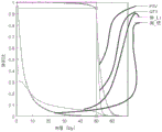
FIG. 10 depicts the dose distribution generated by a fluence map generation method comprising the Chambole-Pock algorithm.
Fig. 11 is a dose-volume histogram of the dose distribution of fig. 10.
Fig. 12 depicts the Moreau-Yosida regularization with a ramp penalty function with parameters t ═ 1 and t ═ 5.
Detailed Description
Disclosed herein are methods for generating a fluence map having a set of beamlet intensities and angles that a radiation therapy system can use to position a radiation source and control the intensity of the generated radiation beam such that a selected/prescribed dose of radiation is applied to a ROI (e.g., a target volume, an illuminated target volume, such as a tumor region), while limiting the amount of radiation applied to one or more organs-at-risk or OARs (e.g., a volume that avoids illumination). That is, given an image (e.g., a three-dimensional digital image) of a patient that includes information about the location and shape of the target to be irradiated, the prescribed dose to the target, the location of the OAR, and the dose limit of the OAR (as well as other dose constraints), the FMO or fluence map generation method calculates a set of beamlet intensities and angles that deliver the prescribed dose to the target while satisfying the OAR dose limit and other constraints.
In some variations, a system configured to generate an fluence map (e.g., a treatment planning system) can be in communication with the radiation therapy system. One variation of a radiation therapy system can include a gantry that is movable (e.g., rotatable) about a patient treatment region, a radiation source mounted on the gantry, and a controller in communication with the gantry and the radiation source. Optionally, the radiation therapy system can include a detector located opposite the radiation source, the detector also being in communication with the controller. The controller may provide signals to the gantry motion system to position the radiation source at a particular location relative to the radiation treatment region, and may provide a series of radiation beamlet data (e.g., pulse intensity, width, duration, etc.) to the radiation source based on a fluence map (e.g., a fluence map produced by any of the fluence map generation methods described herein). The radiation source may comprise a multi-leaf collimator to shape the radiation beam. The system controller may be configured to convert the fluence map into a set of gantry motion and/or multi-leaf collimator instructions (e.g., using a segmentation method). A schematic illustration of a patient 102 positioned within a treatment region of a radiation therapy system 100 is provided in fig. 1A and 1B.
To solve the dose optimization problem, the radiation beam that can be delivered to the patient can be split into beamlets. As shown in FIG. 1B, beamlet 107 can be a portion of the total radiation beam 105 that is defined by the multi-leaf collimator leaf 101 opening at a particular emission location (e.g., emission location 106a relative to patient area 111). Given a discrete set of all possible beam angles (e.g., emission positions) around the gantry 104 (or more generally, around the emission positions of the patient region), a set of all possible beamlets (a subset of which is represented by 106a, 106b, 106c, 106 d) may be selected. For example, a radiation therapy system 100 having m emission positions (e.g., emission angles around a rotatable/circular gantry) may include a multi-leaf collimator 103 that may be positioned at each of the m emission positions. An MLC may have n leaves, and therefore, there may be a total of m × n possible beamlets. In some variations, a radiation therapy system including a binary multi-leaf collimator with 64 leaves on a circular or rotatable gantry with 100 emission positions may have a total of 6400 possible beamlets. Optionally, the total number of possible beamlets may also account for movement of the patient table through the treatment system, such that a system with p patient table positions may have a total of m × n × p possible beamlets. For example, the radiation therapy system described above may have about 10 to about 100 patient table positions, which may produce a number of possible beamlets that is about 64,000(64 × 100 × 10) to about 640,000 (64 × 100 × 100). Thus, a single beamlet may be uniquely identified by its emission position or angle, collimator leaf index, and optionally patient table position. In some variations, the set of candidate beamlets for fluence map generation may be a subset of the total number of possible beamlets. For example, a set of candidate beamlets may be derived by removing beamlets that do not intersect a volume of interest (e.g., illuminate a target volume, etc.) from the total number of possible beamlets. In some variations, all beamlets having a beamlet weight (i.e., beamlet intensity) of 0 may be omitted. Based on the set of candidate beamlets, beamlet weights (e.g., beamlet intensities) that apply the firing of the prescribed dose to the target region/ROI 108 may be calculated to solve a mathematical optimization problem. Fluence Map Optimization (FMO) is a method by which a "best" (i.e., satisfying the imposed constraints) set of beamlet weights can be found. In some variations, the FMO or fluence map generation method may include calculating a set of beamlet weights that deliver a prescription dose to the target while limiting the emission dose to the OARs 110a, 110b, 110 c. The shading of beamlets 106a-106d may represent the weight (e.g., intensity) of the beamlets, with darker shading representing higher beamlet weights (i.e., greater beamlet intensities). The fluence map generated by the FMO method can be such that the emission is applied according to the characteristics depicted in fig. 1A, where the target 108 can receive a prescribed dose of radiation while the radiation exposure of the OARs 110a, 110b, 110c is reduced (e.g., below a selected threshold).
In some variations, the volume of interest (including the irradiation target region and the irradiation-avoidance region) may be divided into a plurality of voxels. Based on the data provided in the treatment plan, which outlines the dose distribution and features prescribed for each VOI in the patient, each voxel may have an acceptable dose range. For example, a voxel in the irradiation target region may have a minimum dose threshold and a maximum dose threshold for a therapeutic end-of-treatment therapeutic target above which the patient may suffer from an undesirable radiation risk. Voxels in the region that are to be avoided from irradiation may have a maximum dose threshold above which undesirable tissue damage may be expected to occur. In some variations, the maximum dose threshold may be lower than the maximum dose threshold of the radiation target region, as tissue in the region that is protected from radiation may be particularly sensitive or susceptible to radiation damage. An acceptable dose range for the voxel may be calculated based on a prescribed dose for the volume of interest prescribed by the treatment plan. Dose constraints for voxels in a volume of interest (VOI) may be used in the fluence map generation methods described herein to derive a set of beamlet weights that satisfy these voxel dose constraints. In some variations, the fluence map generation method can utilize the acceptable dose range for each voxel as a constraint for evaluating whether the set of beamlet weights meets clinical objectives. Alternatively or additionally, the fluence map generation method may aggregate the acceptable dose range for all voxels of the volume of interest into a single-valued constraint (e.g., a single-valued penalty or cost function) for assessing whether the set of beamlet weights meets the clinical goal. In one variation, the fluence map generation method can include an iterative method including assigning a set of beamlet weights to a set of initial values (e.g., zero or baseline values), calculating a dose for each voxel based on a current value of the set of beamlet weights, comparing the calculated dose for each voxel to an acceptable dose range for each voxel to determine whether the current set of beamlet weights meets a clinical goal and/or whether the current set of beamlet weights meets one or more stopping criteria, and if not, updating the set of beamlet weights to a new set of values. Examples of stopping criteriaMay include, but are not limited to, convergence across iterations (e.g., a difference between a set of beamlet weights for a current iteration and a set of beamlet weights for a previous iteration is less than a predetermined threshold; a residual r is less than a threshold ε), and/or a set of beamlet weights reaching an upper bound or number of iterations. The beamlet weights (x) of a previous iteration may be set based on an accelerated near-end gradient method (such as FISTA) with one or more linear penalty functions or any near-end algorithm (such as the Chamboll-Pock method)k-1) Update to a new set of beamlet weights (x) for the current iterationk). The fluence map generation methods described herein can be used to calculate beamlet weights for delivering dose to one or more VOIs within an acceptable dose range for each VOI. Examples of VOIs may include irradiating a target region, avoiding irradiating a region (e.g., an organ at risk, a particular radiation sensitive region), and/or any combination of such regions. The fluence mapping method described in the context of generating a set of beamlet weights based on an acceptable dose range for a single VOI can be extended to generate a set of beamlet weights based on acceptable dose ranges for multiple VOIs.
In the generation of the fluence map, the dose range limits of the VOI and/or voxels may be represented by a penalty function. The penalty function may include a number of penalties that represent VOI or voxel criteria or conditions that the fluence map generation method is attempting to achieve. In some variations, the penalty function, which may be included in a proximal gradient method for fluence map generation (e.g., an accelerated proximal gradient method, such as FISTA), may be based on clinically derived constraints or conditions and/or mathematical constraints or conditions. In some variations, the penalty function may include one or more linear or non-linear (e.g., quadratic) penalties that represent constraints based on an acceptable dose range for each voxel and/or VOI (e.g., that may be extracted from the treatment plan), and one or more linear or non-linear (e.g., quadratic) penalties that represent constraints based on smoothness of the set of beamlet weights. The linear penalty may be a penalty for deviation of the linear weighting from the set of expected constraints when evaluating whether the solution satisfies the set of requirements, and the non-linear penalty (e.g., a quadratic penalty) may be a non-linear weighting with the expectation constraint by a higher order multiplicative factorPenalty of deviation of the set of beams. For example, quadratic (or L) when evaluating whether a solution (e.g., a set of beamlet weights) satisfies a set of requirements (e.g., a dose prescribed by a treatment plan)2) The type penalty may be a large deviation from the desired constraint set (e.g., a large deviation from an acceptable dose range for each voxel or VOI) that is amplified or heavily weighted. Linearity (or L) that can be included in the fluence map generation method1Type) penalty may help converge to a set of beamlet weights that reduces the number of voxels and/or VOIs in which the delivered dose exceeds an acceptable dose range. This can be described as facilitating sparsity in the number of dose violations on a voxel-by-voxel or VOI-by-VOI basis. In some variations, the penalty function may be a linear penalty function (e.g., having only a linear penalty), while in other variations, the penalty function may be a non-linear penalty function (e.g., including one or more non-linear penalties). Some variations of the method for generating a fluence map may include an accelerated proximal gradient method with a single valued penalty function, which may be derived by aggregating the dose constraints for each voxel in the volume of interest. For example, the constraints imposed by the VOIs may be represented by a single valued penalty function, and the accelerated near-end gradient method may iterate a set of beamlet weights based on the single valued penalty function for each VOI in the patient. Other types of penalties that may be included in the penalty function are described in more detail below and/or made into Table 1 of FIG. 2. Any of the fluence map generation methods described herein can optionally include the step of generating one or more penalty functions (e.g., a plurality of single valued penalty functions corresponding to a plurality of VOIs, a plurality of penalty functions for a plurality of sets of voxels) that represent clinical and/or mathematical constraints that may be associated with a particular patient and/or set of VOIs outlined in the treatment plan. In some variations, a smoothing function (e.g., convex regularization, Moreau-Yosida regularization) may be applied to one or more penalty functions if the one or more penalty functions do not satisfy a smoothness criterion for generating the fluence map using the accelerated near-end gradient method.
In some variations, convex optimization techniques may be used to solve fluence map generation problems that may arise during radiation planning. For example, near-end algorithmCan be used to solve very large scale constrained convex optimization problems with non-differentiable objective functions. Some variations may include using a near-end algorithm to solve the fluence map generation problem during treatment planning. In some variations, the method for fluence map generation can include using a multiplier alternating direction method (ADMM), while in other variations, the method for fluence map generation can include using a near-end algorithm, such as the chambole-pack method. The Chambole-Pock method may be able to handle non-quadratic dose penalty terms, including L-based, which are not differentiable in the targetlAnd hard constraints on the amount of radiation delivered to the Planned Target Volume (PTV) and OAR. Another class of algorithms, the accelerated proximal gradient method (e.g., including FISTA), can also be used for the fluence map generation method. These acceleration methods have a convergence speed that has been shown to be optimal for first order methods in a sense.
Disclosed herein are methods for generating a fluence map comprising a set of beamlet intensities that deliver a radiation dose to each VOI within an acceptable dose range for that VOI. For example, the methods may generate a fluence map such that a prescribed radiation dose is delivered to an irradiation target region (e.g., a planned target volume PTV, a tumor region, etc.) while not exceeding a maximum dose for the region to avoid irradiation (e.g., an organ at risk OAR). The acceptable radiation dose range for the VOI (and/or individual voxels within the VOI) may be determined, at least in part, by the treatment plan. In some variations, a treatment plan may be generated based on patient images acquired prior to a treatment session (e.g., during diagnostic imaging) and/or during a prior treatment session or portion.
Some variations for generating fluence maps can include generating beamlet weights or intensity sets using an accelerated proximal gradient method (such as FISTA) or a proximal method (such as the chambole-Pock method). FISTA has been used to solve inverse problems in signal or image processing, particularly for compression, denoising, image recovery, sparse approximation of signals, compressed sensing, and the like. The method of accelerating the proximal gradient may include a gradient having a linear or L-shape1Penalty functions of the penalty term to promote signal sparsity so that the signal can be compressed. Due to signal sparsity and/orData compression and/or image reconstruction are not the primary goals of fluence map optimization and therefore do not consider using accelerated near-end gradient methods (such as FISTA) and near-end methods (such as Chambole-Pock) to generate beamlet weights or intensity sets for radiation therapy planning and systems. However, as described herein, an accelerated proximal gradient method such as FISTA may be able to provide a computationally efficient method to generate fluence maps. The fluence map generation methods described herein can include the use of a fluence map having one or more linear or L' s1Accelerated near-end gradient method of penalty term, such as FISTA. In some variations, L may be smoothed by a regularization method1Penalty term to help reduce discontinuities in the FISTA method. Having a structure containing one or more L1The FISTA of the linear penalty function of the penalty term can be easily implemented on a multi-core processor (CPU and/or GPU), facilitates faster convergence to the final set of beamlet weights, and/or can facilitate better plan consistency with a user or clinician specified planning goal or treatment plan. E.g. having L1FISTA of penalty term can generate a set of beamlet weights that deliver dose to VOI, with L2The accelerated near-end gradient method of penalty terms better conforms to the treatment plan specifications than does the accelerated near-end gradient method. Having L2The fluence map generation method of penalty terms may generate a set of beamlet weights delivering fluence such that a higher proportion of VOIs or voxels receive dose levels outside their acceptable dose range (versus having L)1Method comparisons of penalty terms). Having L2The penalized flow chart generation method may require the user or clinician to over-constrain the problem or iteratively adjust the objective weights, etc., resulting in a higher computational load on the processor and a fluence chart that does not closely conform to the treatment plan specifications
FIG. 1C depicts a variation of the method for generating a fluence map. The method 150 may include selecting 152 one or more volumes of interest (VOIs). The VOI may include one or more irradiation targets (e.g., PTVs, tumor regions, etc.) and/or may include one or more regions that are protected from irradiation. The method 150 may include 154 selecting voxels in one or more VOIs. In some variations, the selected voxels may cumulatively approximate the overall size, shape, of each VOIShape and position. Method 150 may include selecting 156 a beam having an initial beamlet intensity weight x0={xi 0B ═ bi}. Method 150 may include calculating 158 a dose matrix a for each volume of interest based on the set of candidate beamlets b. The dose matrix a may represent the dose per voxel delivered to each of the plurality of voxels by the set of candidate beamlets b. In some variations, the method may include initializing 160 beamlet intensity weights to zero (e.g., initial set of beamlet weights x)0May be an all zero vector). Next, the method may include updating 162 (x) according to a near-end gradient method by using a penalty function including one or more linear penaltiesk-1→xk) Adjusting initial beamlet intensity weights to compute a set of beamlet weights xkThe proximal gradient method is, for example, an accelerated proximal gradient method. This may be an iterative method in which the set of beamlet intensity weights is adjusted based on a penalty function until one or more stopping criteria are met (step 164), and may be any method described below. For example, the accelerated proximal gradient method may be one having one or more L1A FISTA method of cost or penalty function (e.g., as explained further below and represented in fig. 7-8). In some variations, calculating 162 a set of beamlet intensity weights may include adjusting the beamlet intensity weights according to a near-end gradient method or, more generally, a near-end method. In some variations, the stopping criteria may include converging a set of beamlet intensity weights to a set of intensity values. For example, convergence from one iteration to the next may be determined by comparing the set of beamlet intensity weights for iteration x to the set of iterations x-1 and taking the difference in values (e.g., the residual) between the two sets. If the difference is less than a predetermined threshold, a stop criterion may be satisfied and the iteration may be stopped. Other stopping criteria are described below. Alternatively or additionally, the iteration may stop if the number of iterations reaches an upper bound. After satisfying the stopping criteria, method 150 may include calculating a set x including final beamlet intensity weightskThe fluence map of (1).
Additional details regarding these steps are provided below, including illustrative examples.
FIG. 1D depicts the use of L with smoothing1An example of a fluence map (i.e., a set of beamlet intensities) produced by the FISTA method of penalty functions. The fluence map is generated for a radiation therapy system having 100 emission positions (e.g., 100 emission angles around a circular gantry) and a multi-leaf collimator having 60 leaves. In this example, the multi-leaf collimator is a binary multi-leaf collimator. The fluence map in FIG. 1D can represent beamlet intensities for a single patient table position (e.g., a single slice). The intensity of a pixel in the figure may be proportional to the beamlet intensity. When the gantry moves the radiation source from emission position 1 to emission position 100, the multi-leaf collimator opens certain leaves at each of these emission positions. The intensity of the radiation beam at a particular emission position of a particular blade is represented by the intensity of the pixel in the fluence map (where black pixels represent beamlets with zero intensity and white pixels represent beamlets with the maximum allowable intensity). FIG. 1E depicts an axial slice of a simulated patient body in which beamlets of radiation are delivered based on the fluence map of FIG. 1D. The fluence map of FIG. 1D results in dose delivery being concentrated on the ROI 130 with little or no irradiation of other patient regions.
One computational challenge of fluence map optimization is to run using a dose calculation matrix, which is a huge matrix with a very large number of non-zero entries (despite its sparseness). When applied to fluence map optimization, the multiplier alternating direction method requires solving a linear system of equations involving the dose calculation matrix at each iteration. This is important and may result in excessive computational expense. Although decomposition methods may be used to reduce this computational burden, such methods may result in more complex algorithms that are more difficult to implement and require more iterations to converge (which may not be feasible due to the size of the dose calculation matrix) than simple implementations of ADMM. On the other hand, the chambole-pack algorithm and the accelerated near-end gradient method (e.g., FISTA) may be advantageous because they perform matrix-vector multiplication with the dose calculation matrix at each iteration. These methods may not include solving a linear system at each iteration and therefore may not include decomposition methods that make such calculations tractable. The fluence map generation methods described herein can be an efficient algorithm that is naturally parallelized and particularly easy to implement in the controller of a radiotherapy system.
The general fluence map optimization problem considered herein is:

wherein the matrix AiIs a dose calculation matrix for one or more VOIs (e.g., planning target volume PTV, irradiation target region or volume, OAR, irradiation-sparing region or volume, tumor, etc.), N is the number of OARs, matrix D represents a discrete derivative or gradient operator, function Γ, ΦiΨ and Θ are convex penalty functions. Term Γ (A)0x) encourages or defines a minimum radiation level to be delivered to the PTV, and item (A)ix) encourages or requires that the radiation to be delivered to the PTV and OAR not exceed a maximum dose. The regularization terms Ψ (Dx) and Θ (x) encourage a smooth or piecewise smooth non-negative fluence map. Problem (1) may contain most standard fluence map optimization formulas as special cases, with a simple and convenient choice of convex penalty functions.
The optimization algorithms described herein may be able to handle non-quadratic and non-differentiable penalty terms Γ, Φ in fluence map optimizationiAnd Ψ. By using a penalty function as an indicator function (defined in equation (4)), hard constraints can be imposed on the amount of radiation delivered to the PTV and OAR. L is1The advantages of the norm may be applied to fluence map optimization, as will be described further below.
A fluence map generation method is disclosed herein, which includes having one or more penalties (such as L)1Penalty) of the system. In one variation, the Chambole-Pock algorithm may be used on the penalty function Γ, ΦiΨ and Θ solve problem (1) with neighboring operators that can be efficiently evaluated. This may include most fluence map optimization problems encountered in practice, including those with hard constraints and non-differentiable objective functions. In some variations, the fluence map generation method can compriseSmoothing techniques from convex analysis, such as Moreau-Yosida regularization, to smooth the penalty function Γ, ΦiAnd Ψ, and accelerating the near-end gradient method (such as FISTA) to solve the smoothed problem (possibly involving a non-quadratic penalty). As a special case, the smoothed problem may comprise the generation of all fluence maps considered in a unified approach to the inverse problem in Intensity Modulated Radiation Therapy (IMRT).
The fluence map generation method may comprise selecting a penalty function Γ, ΦiΨ and Θ. The problem defined in equation (1) may involve most standard FMO models as special cases, with a simple and convenient choice of penalty functions. Examples of penalty functions that may be used in the fluence map generation methods described herein are summarized in table 1, as shown in fig. 1.
Usually gamma as unilateral secondary penalty

Wherein Is a vector that lists the prescribed dose to be delivered to each voxel in the tumor, but arguably the more preferred choice is to treat Γ as a unilateral L1 norm-based penalty:

L1the general benefits of norms, such as robustness to outliers, also apply in this case. By taking Γ as a unilateral L-based1Allows a significant under-dosing of a small number of voxels in the tumor. This additional flexibility may allow for a reduction in the amount of radiation delivered to the OAR, thereby enabling an overall better treatment plan. Based on L2The penalty of (a) does not allow this flexibility-any significant dose insufficiency will be heavily penalized. In addition, based on L2Tends to allow a slightly under-dosed amount of voxels, whichIs undesirable and consistently leads to slight under-dosing of the target and slight over-dosing of the OAR on the actual FMO problem. In contrast, based on L1The penalty of (2) discourages the presence of small residuals and encourages most residuals to be 0. The third important choice is to use Γ as an index function:

by this selection of Γ, one may combine The hard constraints of (2) are applied to or imposed on the fluence map generation method.
Similar considerations apply to the penalty function ΦiSelected for upper bounds on the dose to encourage or enforce delivery to tumors and OARs. In some variations,. phi.iPossibly including unilateral L-based1Penalty of phii(yi)=αi‖yi-ui‖1Unilateral based on L2Penalty of Or index function penalty

The index function penalty may be able to impose Aix≤uiHard constraints of (2). In some variations, the method may include a penalty function

By selecting the above phii,

Item(s) At Aix<ui, where it is easily satisfied, can be considered to provide additional guidance on how to select x. (We use β)00 because no additional penalty is required for the radiation delivered to the tumor. )
Some variations of the fluence map optimization method and/or the fluence map generation method can include a quadratic regularization term

Where M is the number of beamlets in the IMRT system, x is a vector of beamlet intensities, xmIs the m-th block of x (consisting of beamlet intensities of the m-th beamlet), and each matrix DmRepresenting discrete derivative or gradient operators. The regularization term encourages neighboring beamlets to have similar intensities, resulting in a less chaotic fluence map. The regularization term may facilitate (i.e., accelerate) convergence of the optimization algorithm such that a solution (e.g., a set of beamlet weights or intensities) may be obtained in fewer iterations. However, large components of Dx may be severely penalized (because they are squared) due to the use of a quadratic penalty function, and thus the regularization term tends not to allow any large rise in intensity between adjacent beamlets. This may reduce the generation of treatment plans that are highly suitable for tumors. Similar problems may be encountered in image restoration and reconstruction problems, where the use of a quadratic regularization term does not allow sharp edges in the image to be preserved. An example of a regularization term may be a total variation regularization term

Alternatively, Ψ may be L∞-an index function of a norm sphere. A hard upper limit on intensity variation between adjacent beamlets may be imposed. These choices of Ψ may facilitateIt is further possible to handle the calculation of non-quadratic and non-differentiable penalty terms.
Theta is usually chosen as the indicator function of the non-negative quadrant, from I≥0And (4) showing. In this case, the term Θ (x) in the target simply imposes a constraint of x ≧ 0.Θ may also be chosen to impose an upper limit on the intensity of the beamlets; for example, for a given vector a and b, Θ can be an index function of the set S ═ { x | a ≦ x ≦ b }. Other choices of Θ are possible, such as Or Θ (x) ═ I≥o(x)+∈‖x‖1. These choices of Θ control the size of x, while also forcing x ≧ 0. L penalizing x1Norm may be useful, for example, to limit the number of beamlets emitted during therapy delivery (in other words, to promote sparsity in the fluence map). L penalizing x2The norm may help to limit the total energy delivered during treatment.
In some variations, problem (1) may be solved using the chambole-Pock algorithm, assuming penalty functions Γ, ΦiΨ and Θ have neighbor operators that can be efficiently evaluated. This may include one or more (e.g., all) of the penalty functions described herein. Numerical results of the FMO problem are also disclosed

This is a special case of problem (1), where ΦiFrom equations (3) and Ψ(YN+1)=η‖YN+1‖1and Θ ═ I≥0It is given. Numerical results of the FMO problem are also disclosed

This is a special case of problem (1), where ΓFor the index function, from equation (2),
 for 1, … …, N, phi0=0、Ψ(yN+1)=η‖yN+1‖1And Θ ═ I≥0It is given.
Table 2 summarizes the symbols and definitions used herein.
In convex analysis, when in the following semicontinuous, the function f: referred to as "closed". This is a mild condition that most convex functions encountered in practice satisfy. When used for at least one point
 Time, function f:
 referred to as "normal".
Index and projection functionIs provided with Is a closed convex set. The index function of C is a convex function I defined byC:

The indicator function may be used for convex optimization (including any of the methods described herein) for applying a hard constraint on the optimization variable x. The problem of minimizing f (x) subject to x ∈ C is equivalent to minimizing f (x) + IC(x) The problem of minimization. The index function being highly inseparableBut this does not present any problem for near-end algorithms that are naturally able to handle the indicator function.
When in use For j equal to 1, …, m, the index function of C is I[a,b]Rather than to
 And (4) showing. Symbol
 Wherein
 Representation collection
 In which the inequality is
 Is interpreted as representing
 For
For j 1.
The function projected on C is represented by PCRepresents:

when C is ═ a, b]mThe function projected onto C will be represented by P[a,b]Rather than to And (4) showing. Symbol
 Projecting representations onto collections
 A function of (c). Attention is paid to
 Maximum (x, l) (where the maximum is acquired in a component wise manner).
ConjugationFunction f: is a function f defined by*:

Convex conjugation f*Is a "dual version" of f, tends to occur when the dual problem is formed in convex optimization. When f is closed and convex, f can be represented by the formula f ═ f**From f*And (4) recovering.
The following "separable sum" rule for conjugation will be useful in the future. Let f be the sum of one partitionable block:

then Input vector x1、……、xKCan be viewed as a block of a larger vector x, and a vector z1、……、zKCan be considered as a block of a larger vector z.
Neighbor operatorSetting f: is a normal closed convex function. f's neighbor operator (also called "neighbor operator"), with parameter t>0, is defined as follows

The near-end algorithm is an iterative algorithm that requires the evaluation of various neighboring operators at each iteration. For many important convex penalty functions, the neighborhood operator has a simple closed form representation and can be very efficiently evaluated at a computational cost that is linear with m. The term "proximately" may describe a function that can efficiently evaluate its proximity operator.
Several useful rules for evaluating the neighbor operators are listed in Table 3, as shown in FIG. 4. In this table, assume functions f and fkA normal normally closed protrusion. Equation 3.3 is referred to as the Moreau decomposition and is very useful for the near-end algorithm because it represents f according to its neighborhood operators*The neighbor operator of (2). If f's neighbor operators can be evaluated efficiently, then f can be evaluated equally efficiently*The neighbor operator of (2). (the term "decompose" means that x has been decomposed into sums of adjacent operator terms.) in equation 3.1, function g is a function fkMay be used to separate the sums. Input vector x1、...、xKCan be viewed as a block of a larger vector x. According to this rule, the neighbor operators evaluating the separable sum g are reduced to evaluate the function f independentlykThe neighbor operator of (2). Rule 3.4 may be derived by using Moreau decomposition to derive from its conjugate f*(z)=I[0,1](z) the neighbor operator expression f (x) | x+‖1The neighbor operator of (2). In the last two rows of the table, pjRepresentation vector proxtg(x) The j-th component of (a), and xjRepresenting the jth component of x.
The near-end gradient method is one of the most basic near-end algorithms, which solves the following form of optimization problem
Minimizing f (x) + g (x) (7)
Where f and g are closed-convex functions and f is differentiable, with a rischtz continuous gradient. Recording of fixed step t in Algorithm 1 (FIG. 5)>A near-end gradient iteration of 0. If t is less than or equal to 2/L, where L is The rischz constant of (a), then ensures that the near-end gradient iteration converges to the minimum of (7), assuming that there is a minimum.
In which g (x) is ═ IC(x) In the special case of (2), where C is a closed-convex set and ICIs an index function of C, and problem (7) is equivalent to

Iteratively reducing adjacent gradients to

Wherein P isCIs a function of the projection on C. In this case, the proximal gradient method is called a projection gradient method.
Although a near-end gradient method with a fixed step size may be used, a significant advantage of the near-end gradient method is that there is a simple and efficient linear search procedure that can be used to adaptively select the step size at each iteration. A variation of the near-end gradient method with linear search is presented in algorithm 2 (fig. 6).
A variation of the fluence map generation method can include an accelerated version of the projection gradient method and a proximal gradient method for radiation therapy planning. For example, FISTA (an abbreviation for "fast iterative shrink-threshold algorithm"). FISTA is an accelerated version of the proximal gradient method to solve problem (7) where (as before) f and g are closed-convex functions, and f is differentiable, with a RippSitz continuous gradient (RippSitz constant L)>0). The fixed step size t is represented in algorithm 3 (FIG. 7)>0, one variation of the FISTA iteration. When t is 1/L, the iteration is at 1/k2While the near-end gradient iteration converges only at a rate of 1/k. For the first order method, the convergence rate of FISTA is 1/k2May be desirable or optimal.
Optimization problem of solving canonical form by using Chamboll-Pock algorithm
Minimizing f (x) g (ax) (9)
Wherein f: and g:
 is a normal closed convex function and
 is a matrix. This canonical problem form may be useful because many important problems in areas such as signal and image processing may be represented by form (9), where f, g, and a are particularly simply chosen. "simple" specifically means that the neighborhood operators of f and g can be evaluated inexpensively, and the multiplication of a and AT can be performed efficiently. The fluence map optimization problem considered herein can be conveniently expressed in this form. (problem form (9) can be solved by the Fenchel-Rockafella dual process, which starts from this problem form.)
The chambole-Pock algorithm is a primitive dual algorithm, meaning that it solves both the primitive problem (9) and the dual problem, i.e. it solves both the primitive problem and the dual problem

A variant of the chambole-pack iteration with steps s and t and an over-relaxation parameter rho e (0,2) is represented in algorithm 5 (fig. 9). In each iteration, we perform A and ATThe matrix vector multiplication of (a), but does not require solving a linear system involving a. This is an advantage of the chambole-pack algorithm over methods based on Douglas-Rachford (such as ADMM). Algorithm 5 (fig. 9) is an over-relaxed version of the chambole-pack algorithm. The step length s and t need to satisfy st | | A | | non-woven phosphor2Less than or equal to 1, wherein L is2Norm-induced matrix norm. When this step size constraint is met, algorithm 5 can be expected to converge to the minimum element of problem (9) (assuming there is a minimum element). Although one choice for s and t is s-t-1/| | | a |, by adjusting s and tThe values may significantly improve convergence.
While the chambole-Pock algorithm may help produce a solution to the fluence map optimization problem, one may wish to achieve faster convergence by using an acceleration method such as FISTA, which has O (1/k)2) Is the optimal (in a first order approach) convergence speed (where k is the number of iterations). When the acceleration method can be applied, O (1/k)2) The convergence speed can be significantly faster than the O (1/k) convergence speed of the Chambole-Pock algorithm. Another advantage of FISTA is that a simple and efficient linear search procedure can be used, which means that step selection is not difficult. Therefore, for fluence map optimization, the accelerated proximal gradient method (specifically FISTA) may be preferably used.
The difficulty with fluence map optimization using the proximal gradient method is that the optimization problem must first be expressed in form (7), which has a differentiable function f and a simple (i.e. adjacent) function g, and this is not always possible. This challenge can be solved by smoothing the non-differentiable penalty function present in problem (1). Convex analysis provides a compact method of smoothing an undifferentiated convex function-Moreau-Yosida regularization.
Moreau-Yosida regularizationSetting phi: are closed and convex. Parameter gamma>The definition of Moreau-Yosida regularization at 0 is as follows

Can indicate phi(γ): Is a convex differentiable approximation of phi, and phiγThe gradient of (A) is given by the following formula

φ(γ)The gradient of (A) is a RippSitz continuum with a RippSitz constant L ═ 1/t. The parameter γ controls the amount of smoothing-for small values of γ, there is little smoothing, and φ(γ)Very similar to phi. Accordingly, when γ is small, the liphoz constant L is large. Fig. 12 shows the Moreau-Yosida regularization of the ramp penalty function for parameters t ═ 1 and t ═ 5. Note that the Moreau-Yosida regularization is differentiable, while the ramp penalty function is not.
Attention is paid to

When phi is equal to ICThen, for the closed convex set C index function, we have

This is an approximation function that serves as the basis for the existing unified approach to the inverse problem in IMRT. The gradient of the approach function follows equation (12):
smoothed FMO problemNext, question (1) is replaced by the following smoothed question

Function Γ(γ),Φi (γ)And Ψ(γ)Is the Moreau-Yosida regularization (function Γ, Φ from problem (1))iAnd parameter γ >0 for Ψ. The function Θ may not be smoothed. In some variations, the same smoothing parameter γ may be used for each penalty function, but other smoothing parameters may also be used. Assuming a (possibly non-differentiable) function Γ, ΦiΨ and Θ have neighbor operators that can be efficiently evaluated.
As a special case, when F, phiiAnd Ψ is considered an index function, their Moreau-Yosida regularization is an approximation function (defined in equation (13)) and can be used with the fluence map optimization problem considered in the unified approach to the IMRT inverse problem. The smoothed problem may be solved using projection gradients instead of accelerated projection gradients.
The smoothed problem as shown in equation (14) can be solved using the accelerated near-end gradient method. The problem (14) has the form (7) wherein

And g ═ Θ. When using the accelerated near-end gradient method, each iteration may include calculating the gradient of f and the neighborhood operator of g. The neighbor operator for g Θ can be efficiently calculated by assumptions. Thus, it is still only shown how to efficiently calculate the gradient of f.
According to the chain rule, the gradient of f is given by

The gradient on the right can be calculated using equation (12):


each of these gradients can be efficiently calculated because we assume Γ, ΦiAnd the neighbor operator of Ψ is inexpensive.
When solving the problem (7) using the near-end gradient method or FISTA with a fixed step size, the step size is typically chosen to be t-1/L, where L is The liphoz constant of (a). In practice, the amount of the liquid to be used,
 the liphoz constant of (a) is generally not exact, so L is considered to be
 The best available upper bound for the lipschitz constant. When f is given by equation (15), the upper bound of the Liphoz constant is

The upper bound of the liphoz constant may be too pessimistic, but when solving the problem (14) by the near-end gradient method or FISTA, a linear search procedure may be used.
In the following, a convex penalty function Γ, Φ is assumediΨ and Θ having neighboring operators that can be efficiently evaluated, one example of how to solve the general fluence map optimization problem (1) using the chambole-pack algorithm is described and depicted. This may include one or more (e.g., all) of the penalty functions previously described.
Algorithm derivation
Problem (1) can be expressed in canonical form (9) by taking f ═ Θ and the following formula

(Note A)0Two occurrences in A. ) The fluence map optimization problem has been expressed in form (9), which is applicable to the chambole-Pock algorithm, which is used only to show how to compute f and g*The neighbor operator of (2).
The neighborhood operator of f is only the neighborhood operator of Θ, and can be evaluated efficiently in some variations. To understand how to evaluate g*First note that g is a separable sum. Separable summation rule of conjugates

Let t >0 separable sum rule of neighbor operators

The Moreau decomposition theorem depends on the functions Γ, ΦiAnd Ψ's neighbor expression function Γ*, And Ψ*The neighbor operator of (2). It is assumed that these proximity operators are cheap. Therefore, g can be effectively evaluated*The neighbor operator of (2).
Table 1, depicted in FIG. 2, gives the most typical penalty functions Γ, ΦiΨ and Θ. These formulas result from the results listed in section 3, including the scaling and shifting rules (3.2).
Numerical results
The Chambole-Pock algorithm can be used for solving the optimization problem of the fluence map

Referring now to fig. 10, a PTV is depicted by outline 1000. The area receiving at least 50 grays depicted by outline 1002 almost completely coincides with PTV outline 1000.
Stop criteria for FISTA
As described above, once the stopping criteria are obtained (step 164 of the method 150), the iterative portion of the fluence map generation method (e.g., an accelerated proximal gradient method such as FISTA or a proximal algorithm such as Chambole-Pock) can be exited. The method of flux map generation or optimization including FISTA may have stopping criteria as described below.
The proximal gradient method (such as the accelerated proximal gradient method, including FISTA, as described herein) attempts to solve the original problem by iteration:

the iteration is

(here, h: is a suitable closed convex function, g:
 is convexly differentiable and has a Leptoschitz continuous gradient, and t>0). (11) Is that the original optimality condition of

The near-end gradient method may iterate to find r, such that

And r is almost equal to 0, this means that (13) is almost satisfied and x is close to optimal.

Equation (12) may be equivalent to using (14)

The condition (15) has almost the desired form, and can be equivalently rewritten as follows:

condition (16) shows that x+Almost optimal as long as the residual error

Is small. Thus, a possible stopping criterion may be | <e. In some variations, the stopping criterion may include a "relative" residual, in which case the stopping criterion may be about:

FISTA is solved by the following iteration (11)


Equation (17) may be equivalent to:

the residual can therefore be written as:

to obtain a stopping criterion for FISTA.
Or, if known With a lipschitz constant L, the stopping criterion is less computationally intensive (i.e., it may not be necessary to evaluate g at xkThe gradient of) may include:


stopping standard of Chambole-Pock
The method of generation or optimization of the fluence map comprising the chambole-pack may have stopping criteria as described below. The chambole-Pock solves the original problem through iteration:

solving dual problems simultaneously

The iteration is

xn+1=proxrG(xn–τKTzn+1)(20)

In one variation, the stopping criterion may be based on a dual gap, where a dual feasible variable is available. In the fluence map estimation problem, G is an index function of the non-negative quadrant, and can be shown to be G*An index function that is not a positive quadrant. If the condition-K is satisfiedTz ≦ 0, then z may be dual feasible. In some variations, zn+1This may not be satisfied. In addition, in the fluence map estimation problem, only when z ═ is (z)1,z2,z3) Satisfies | z2‖∞Lambda and | z3‖∞When lambda is less than or equal to F*(z) may be finite. These are additional constraints that z must satisfy dual feasibility.
Alternatively, the stop criterion may be based on the residual in the KKT condition. The Karush-Kuhn-Tucker (KKT) condition is a set of necessary conditions for solving the optimization problem to be optimal, and can be expressed as an equation set and an inequality including a cost function and an input constraint. This may be used in certain variations where the dual gap based stopping criteria may be computationally intensive and/or where the conditions of the dual gap based stopping criteria are not met. The KKT condition of problem (18) can be written as


The core idea of the stopping criterion is to find r1And r2So that


And r is1And r2Almost equal to 0. If these conditions are met, this means that (22) and (23) are nearly met and x and z may be near optimal.
Notably, x can be written as:

using (24), equation (19) can be rewritten as follows:

and (20) is equivalent to

Therefore, equation (25) can be equivalently expressed as:

conditions (26) and (27) together indicate (x)n+1,zn+1) Is an almost optimal pair of original and dual variables, provided that the residual is


is small. Thus, a variation of the possible stop criteria of the chambole-pack may be | r1‖ <E and |<E. In some variations, the stop signQuasi may include "relative" residuals, in which case the stopping criterion may be about:

the stopping criterion may include an additional multiplication by K (e.g., K (x) per iterationn-xn+1)). To help reduce K and KTThe computational load of the additional multiplications of, a variation of the method used to generate the fluence map, including the chambole-pack method, may be to check the stopping criterion or residual at some iterations, but not others. For example, the residual may be computed approximately once every 20 iterations rather than once every iteration. In other variations, the residual may be computed every 2 iterations, every 5 iterations, every 10 iterations, every 12 iterations, every 25 iterations, every 30 iterations, every 50 iterations, and so on. Alternatively, the residual may be calculated at each iteration.
The FMO or fluence map generation methods described herein can be implemented by a computer or controller, for example, in a computer program or software stored in a machine-readable storage medium. The computer or controller may be part of a radiation therapy system such that, for example, the fluence map produced by the FMO or fluence map production methods described herein can be used to position the radiation source at a particular angle relative to the ROI or patient (by rotating the gantry on which the radiation source is mounted) and adjust the intensity of the beam produced by the radiation source in accordance with the fluence map. Alternatively or additionally, the FMO or fluence map generation methods described herein can be implemented by a computer or controller separate from the radiation therapy system. The resulting fluence map can then be transferred to a controller of the radiation therapy system using a machine-readable transmission medium, such as (but not limited to) an electrical, optical, acoustical or other type of medium suitable for transmitting electronic information.
Controller
A system (e.g., a treatment planning system) that may be configured to generate an fluence map based on treatment planning parameters may include a controller in communication with a radiation treatment system and/or a clinician and/or operator. The controller may include one or more processors and one or more machine-readable memories in communication with the one or more processors. The controller may be connected to the radiation therapy system and/or other systems through wired or wireless communication channels. In some variations, the controller of the treatment planning system may be located in the same or a different room as the patient. For example, the controller may be coupled to a patient platform or disposed on a cart or medical cart adjacent to the patient and/or operator.
The controller may be implemented in accordance with any number of general purpose or special purpose computing systems or configurations. Various exemplary computing systems, environments, and/or configurations that may be suitable for use with the systems and devices disclosed herein may include, but are not limited to, software or other components within or embodied on personal computing devices, network appliances, server or server computing devices (e.g., routing/connection components), portable (e.g., handheld) or laptop devices, multiprocessor systems, microprocessor-based systems, and distributed computing networks.
Examples of portable computing devices include smartphones, Personal Digital Assistants (PDAs), cell phones, tablets, tablet phones (personal computing devices larger than smartphones but smaller than tablets), wearable computers in the form of smartwatches, portable music devices, and so forth.
Processor with a memory having a plurality of memory cells
In some embodiments, a processor may be any suitable processing device configured to execute and/or execute a set of instructions or code and may include one or more data processors, image processors, graphics processing units, physical processing units, digital signal processors, and/or central processing units. The processor may be, for example, a general purpose processor, a Field Programmable Gate Array (FPGA), an Application Specific Integrated Circuit (ASIC), or the like. The processor may be configured to run and/or execute application processes and/or other modules, processes, and/or functions associated with the system and/or a network (not shown) associated therewith. Underlying device technologies of various component types may be provided, such as Metal Oxide Semiconductor Field Effect Transistor (MOSFET) technologies (e.g., Complementary Metal Oxide Semiconductor (CMOS)), bipolar technologies (e.g., Emitter Coupled Logic (ECL)), polymer technologies (e.g., silicon-conjugated polymers and metal-conjugated polymer-metal structures), hybrid analog and digital, and so forth.
Memory device
In some embodiments, the memory may include a database (not shown), and may be, for example, Random Access Memory (RAM), memory buffers, hard drives, erasable programmable read-only memory (EPROM), electrically erasable read-only memory (EEPROM), read-only memory (ROM), flash memory, and the like. The memory may store instructions to cause the processor to perform modules, processes, and/or functions associated with the system, such as calculating a fluence map based on the treatment plan and/or clinical goals, dividing the fluence map into radiation treatment system instructions (e.g., which may direct the gantry, the treatment radiation source, the multi-leaf collimator, and/or the radiation treatment system and/or any other component of the diagnostic or treatment planning system), and image and/or data processing associated with the treatment plan and/or delivery.
Some embodiments described herein relate to a computer storage product with a non-transitory computer-readable medium (which may also be referred to as a non-transitory processor-readable medium) having instructions or computer code thereon for performing various computer-implemented operations. The computer-readable medium (or processor-readable medium) is non-transitory in the sense of not including a transitory propagating signal per se (e.g., a propagating electromagnetic wave carrying information on a transmission medium such as space or cable). The media and computer code (also can be referred to as code or algorithms) may be those designed and constructed for the specific purpose. Examples of non-transitory computer readable media include, but are not limited to, magnetic storage media such as hard disks, floppy disks, and magnetic tape; optical storage media such as compact discs/digital video discs (CD/DVD); compact disc read only memory (CD-ROM) and holographic devices; magneto-optical storage media such as optical disks; solid state storage devices, such as Solid State Drives (SSDs) and Solid State Hybrid Drives (SSHDs); a carrier signal processing module; and hardware devices that are specially configured to store and execute program code, such as Application Specific Integrated Circuits (ASICs), Programmable Logic Devices (PLDs), Read Only Memory (ROM) and Random Access Memory (RAM) devices. Other embodiments described herein relate to computer program products that may include, for example, the instructions and/or computer code disclosed herein.
The user interface may serve as a communication interface between the operator or clinician and the treatment planning system. The user interface may include an input device and an output device (e.g., a touchscreen and a display) and be configured to receive input data and output data from one or more of the support arm, the external magnet, the sensor, the delivery device, the input device, the output device, a network, a database, and a server. Sensor data from one or more sensors may be received by the user interface and output by one or more output devices visually, audibly, and/or through tactile feedback. As another example, operator controls of an input device (e.g., joystick, keyboard, touch screen) may be received by a user and then processed by a processor and memory for outputting control signals to one or more of the support arm, external magnet, intraluminal device, and delivery device.
Some variations of the treatment planning system for generating an fluence map can include a display device that can allow an operator to view graphical and/or textual representations of the fluence map and/or dose distribution and/or region of interest and/or volume of interest and/or patient anatomical images and/or patient data (e.g., physiological and/or biological), etc. In some variations, the output device may include a display device including at least one of a Light Emitting Diode (LED), a Liquid Crystal Display (LCD), an electroluminescent display (ELD), a Plasma Display Panel (PDP), a Thin Film Transistor (TFT), an Organic Light Emitting Diode (OLED), an electronic paper/electronic ink display, a laser display, and/or a holographic display.
Communication
In some embodiments, the treatment planning system may communicate with other computing devices (not shown) via, for example, one or more networks, each of which may be any type of network (e.g., wired network, wireless network). A wireless network may refer to any type of digital network that is not connected by any type of cable. Examples of wireless communication in a wireless network include, but are not limited to, cellular, radio, satellite, and microwave communication. However, wireless networks may be connected to wired networks to connect with the internet, other operator voice and data networks, business networks, and personal networks. Wired networks are typically carried by twisted copper pairs, coaxial cables, and/or fiber optic cables. There are many different types of wired networks, including Wide Area Networks (WANs), Metropolitan Area Networks (MANs), Local Area Networks (LANs), the Internet (IAN), Campus Area Networks (CANs), Global Area Networks (GANs) (e.g., the internet), and Virtual Private Networks (VPNs). In the following, a network refers to any combination of wireless, wired, public, and private data networks interconnected typically by the internet to provide a unified networking and information access system.
Cellular communication may include technologies such as GSM, PCS, CDMA or GPRS, W-CDMA, EDGE or CDMA2000, LTE, WiMAX, and 5G network standards. Some wireless network deployments combine networks from multiple cellular networks or use a mix of cellular, Wi-Fi, and satellite communications. In some embodiments, the systems, apparatus, and methods described herein may include radio frequency receivers, transmitters, and/or optical (e.g., infrared) receivers and transmitters to communicate with one or more devices and/or networks.
Claims (34)
1. A method for calculating a fluence map for radiation therapy, the method comprising:
selecting a first volume of interest;
selecting a first plurality of voxels within the first volume of interest, wherein each of the first plurality of voxels has an acceptable dose range;
selecting a set of candidate beamlets b ═ biWith initial beamlet intensity weight x0={xi 0};
Calculating a dose matrix A for the first volume of interest based on the set of candidate beamlets, b, wherein the dose matrix A represents the dose per voxel delivered by the set of candidate beamlets to each of the first plurality of voxels; and
according to the near-end gradient method (x) by using a penalty function comprising one or more linear penaltiesk-1→xk) Adjusting initial beamlet intensity weights to compute a set x of final beamlet intensity weightskThe near-end gradient method iterates the initial beamlet intensity weights until the adjusted beamlet intensity weights converge to a final set of beamlet intensity weights such that a variation between iterations of the beamlet intensity weights is less than a predetermined residual criterion.
2. The method of claim 1, wherein the proximal gradient method is an accelerated proximal gradient method.
3. The method of claim 2, wherein the proximal gradient method is a Fast Iterative Shrinkage Threshold Algorithm (FISTA).
4. The method of any of claims 1-3, wherein the one or more linear penalties include one or more L1And (6) punishing.
5. The method of any of claims 1-3, wherein the penalty function has been smoothed such that it is differentiable.
6. The method of claim 5, wherein the penalty function is smoothed using Moreau-Yosida regularization.
7. The method of any of claims 1-3, wherein the set of initial beamlet intensity weights { x }0Is an all-zero vector.
8. According to claimThe method of any of claims 1-3, wherein the beamlets in the set of candidate beamlets b are in a smaller set of emission angles { f }iAre divided between.
9. The method of claim 8, wherein the set of emission angles { f } fiIncludes a plurality of emission angles around a patient area of the radiotherapy apparatus.
10. The method of claim 9, wherein the plurality of emission angles are evenly distributed 360 degrees around the patient region.
11. The method of any of claims 1-3, wherein the near-end gradient penalty function includes one or more secondary penalties.
12. The method of claim 11, wherein the one or more secondary penalties include one or more L | _ penalties2And (6) punishing.
13. The method according to any one of claims 1-3, wherein the penalty function penalizes voxel dose shifts outside the acceptable dose range.
14. The method of claim 13, wherein the penalty function is a single valued penalty function that aggregates the voxel dose offset outside an acceptable dose range for all of the first plurality of voxels in the first volume of interest.
15. The method of any one of claims 1-3, wherein an acceptable dose range for each of the first plurality of voxels is determined at least in part by a treatment plan.
16. The method according to any one of claims 1-3, wherein the method further comprises:
selecting a second volume of interest;
selecting a second plurality of voxels within the second volume of interest, wherein each of the second plurality of voxels has an acceptable dose range; and
wherein calculating the dose matrix A further comprises calculating the dose matrix A for the first volume of interest and the second volume of interest based on the set of candidate beamlets b, wherein the dose matrix A represents the dose per voxel delivered by the set of candidate beamlets b to each of the first plurality of voxels and the second plurality of voxels.
17. The method of any of claims 1-3, further comprising segmenting the fluence map into a set of multi-leaf collimators and radiation source positioning instructions.
18. A system for calculating a fluence map for radiation therapy, the system comprising:
a processor configured to:
selecting a first volume of interest;
selecting a first plurality of voxels within the first volume of interest, wherein each of the first plurality of voxels has an acceptable dose range;
selecting a set of candidate beamlets b ═ biWith initial beamlet intensity weight x0={xi 0};
Calculating a dose matrix A for the first volume of interest based on the set of candidate beamlets, b, wherein the dose matrix A represents the dose per voxel delivered by the set of candidate beamlets to each of the first plurality of voxels;
updating (x) according to the near-end gradient method by using a penalty function containing one or more linear penaltiesk-1→xk) Adjusting the initial beamlet intensity weights to compute a set x comprising final beamlet intensity weightskThe near-end gradient method updates the initial beamlet intensity weights iteratively until the adjusted beamlet intensity weights converge to a final set of beamlet intensity weights such that theA variation between iterations of the beamlet intensity weights is less than a predetermined residual criterion; and
storing the fluence map in a processor memory.
19. The system of claim 18, wherein the proximal gradient method is an accelerated proximal gradient method.
20. The system of claim 19, wherein the accelerated near-end gradient method is a Fast Iterative Shrinkage Threshold Algorithm (FISTA).
21. The system of any of claims 18-20, wherein the one or more linear penalties include one or more L | _ s1And (6) punishing.
22. The system of any of claims 18-20, wherein the penalty function has been smoothed such that it is differentiable.
23. The system of claim 22, wherein the penalty function is smoothed using Moreau-Yosida regularization.
24. The system of any of claims 18-20, wherein the penalty function penalizes voxel dose shifts outside the acceptable dose range.
25. The system of claim 24, wherein the penalty function is a single valued penalty function that aggregates the voxel dose offset outside an acceptable dose range for all of the first plurality of voxels in the first volume of interest.
26. The system of any of claims 18-20, wherein an acceptable dose range for each of the first plurality of voxels is determined at least in part by a treatment plan.
27. The system of any one of claims 18-20, wherein the processor is further configured to:
selecting a second volume of interest;
selecting a second plurality of voxels within the second volume of interest, wherein each of the second plurality of voxels has an acceptable dose range; and
wherein calculating the dose matrix A further comprises calculating the dose matrix A for the first volume of interest and the second volume of interest based on the set of candidate beamlets b, wherein the dose matrix A represents the dose per voxel delivered by the set of candidate beamlets b to each of the first plurality of voxels and the second plurality of voxels.
28. The system of any one of claims 18-20, further comprising a radiation therapy system including a therapeutic radiation source movable around a patient region and configured to apply beamlets of radiation to the patient region according to the fluence map.
29. The system of claim 18, wherein the beamlets in the set of candidate beamlets b are in a smaller set of emission angles { f }iAre divided between.
30. The system of claim 29, wherein the set of emission angles { f } fiComprises a plurality of emission angles around a patient area of the radiation therapy device.
31. The system of claim 30, wherein the plurality of emission angles are evenly distributed 360 degrees around the patient region.
32. The system of claim 28, wherein the radiation therapy system further comprises a multi-leaf collimator disposed in a beam path of the therapeutic radiation source, and wherein the processor is configured to segment the fluence map into a set of multi-leaf collimator instructions and transmit the instructions to the radiation therapy system.
33. The system of claim 28, wherein the radiation therapy system further comprises one or more PET detectors.
34. The system of claim 28, wherein the therapeutic radiation source is movable around the patient region at a speed of at least about 40 RPM.
Applications Claiming Priority (3)
| Application Number | Priority Date | Filing Date | Title |
|---|---|---|---|
| US201662305974P | 2016-03-09 | 2016-03-09 | |
| US62/305,974 | 2016-03-09 | ||
| PCT/US2017/021647 WO2017156316A1 (en) | 2016-03-09 | 2017-03-09 | Fluence map generation methods for radiotherapy |
Publications (2)
| Publication Number | Publication Date |
|---|---|
| CN109152928A CN109152928A (en) | 2019-01-04 |
| CN109152928B true CN109152928B (en) | 2021-05-28 |
Family
ID=59789757
Family Applications (1)
| Application Number | Title | Priority Date | Filing Date |
|---|---|---|---|
| CN201780022728.6A Active CN109152928B (en) | 2016-03-09 | 2017-03-09 | Method and system for calculating a fluence map for radiation therapy |
Country Status (5)
| Country | Link |
|---|---|
| US (1) | US10918884B2 (en) |
| EP (1) | EP3426345B1 (en) |
| JP (1) | JP6889495B2 (en) |
| CN (1) | CN109152928B (en) |
| WO (1) | WO2017156316A1 (en) |
Families Citing this family (39)
| Publication number | Priority date | Publication date | Assignee | Title |
|---|---|---|---|---|
| CN106563211B (en) | 2011-03-31 | 2019-10-18 | 反射医疗公司 | For system and method used in the radiotherapy in transmitting guidance |
| WO2017156316A1 (en) | 2016-03-09 | 2017-09-14 | Reflexion Medical, Inc. | Fluence map generation methods for radiotherapy |
| US9855445B2 (en) | 2016-04-01 | 2018-01-02 | Varian Medical Systems, Inc. | Radiation therapy systems and methods for delivering doses to a target volume |
| JP7178714B2 (en) | 2016-11-15 | 2022-11-28 | リフレクション メディカル, インコーポレイテッド | Radiation Therapy Patient Platform |
| WO2018093849A1 (en) | 2016-11-15 | 2018-05-24 | Reflexion Medical, Inc. | Methods for radiation delivery in emission-guided radiotherapy |
| EP3357539A1 (en) * | 2017-02-02 | 2018-08-08 | Koninklijke Philips N.V. | Warm start initialization for external beam radiotherapy plan optimization |
| WO2018195151A1 (en) * | 2017-04-18 | 2018-10-25 | The Regents Of The University Of California | System and method for optimized dynamic collimator rotation in volumetric modulated arc therapy |
| CN114712730A (en) | 2017-05-30 | 2022-07-08 | 反射医疗公司 | Method for real-time image-guided radiation therapy |
| US10843011B2 (en) | 2017-07-21 | 2020-11-24 | Varian Medical Systems, Inc. | Particle beam gun control systems and methods |
| US11712579B2 (en) | 2017-07-21 | 2023-08-01 | Varian Medical Systems, Inc. | Range compensators for radiation therapy |
| US10549117B2 (en) | 2017-07-21 | 2020-02-04 | Varian Medical Systems, Inc | Geometric aspects of radiation therapy planning and treatment |
| US10183179B1 (en) | 2017-07-21 | 2019-01-22 | Varian Medical Systems, Inc. | Triggered treatment systems and methods |
| US10092774B1 (en) | 2017-07-21 | 2018-10-09 | Varian Medical Systems International, AG | Dose aspects of radiation therapy planning and treatment |
| US11590364B2 (en) | 2017-07-21 | 2023-02-28 | Varian Medical Systems International Ag | Material inserts for radiation therapy |
| CN111372653B (en) | 2017-09-22 | 2022-06-17 | 反射医疗公司 | System and method for shuttle mode radiation delivery |
| EP3710111B1 (en) | 2017-11-16 | 2021-12-29 | Varian Medical Systems, Inc. | Increased beam output and dynamic field shaping for radiotherapy system |
| JP7409672B2 (en) | 2018-02-13 | 2024-01-09 | リフレクション メディカル, インコーポレイテッド | Beam station treatment planning and radiation delivery methods |
| EP3530319A1 (en) * | 2018-02-21 | 2019-08-28 | Elekta Limited | Methods for inverse planning |
| CN108805975B (en) * | 2018-05-29 | 2021-03-16 | 常熟理工学院 | Microscopic 3D reconstruction method based on improved iterative shrinkage threshold algorithm |
| US10910188B2 (en) | 2018-07-25 | 2021-02-02 | Varian Medical Systems, Inc. | Radiation anode target systems and methods |
| US11651847B2 (en) | 2018-08-31 | 2023-05-16 | The Board Of Regents Of The University Of Texas System | Dose volume histogram and dose distribution based autoplanning |
| WO2020061179A1 (en) * | 2018-09-19 | 2020-03-26 | The University Of Chicago | System and method for multi-site radiotherapy |
| WO2020150505A1 (en) | 2019-01-16 | 2020-07-23 | Reflexion Medical, Inc. | Methods for setup corrections in radiation therapy |
| US11052265B2 (en) * | 2019-02-11 | 2021-07-06 | Troy Long | Fluence map optimization for field-in-field radiation therapy |
| US10814144B2 (en) | 2019-03-06 | 2020-10-27 | Varian Medical Systems, Inc. | Radiation treatment based on dose rate |
| US11116995B2 (en) | 2019-03-06 | 2021-09-14 | Varian Medical Systems, Inc. | Radiation treatment planning based on dose rate |
| US11103727B2 (en) | 2019-03-08 | 2021-08-31 | Varian Medical Systems International Ag | Model based PBS optimization for flash therapy treatment planning and oncology information system |
| US11090508B2 (en) | 2019-03-08 | 2021-08-17 | Varian Medical Systems Particle Therapy Gmbh & Co. Kg | System and method for biological treatment planning and decision support |
| EP3721940A1 (en) * | 2019-04-12 | 2020-10-14 | RaySearch Laboratories AB | Generating a plurality of treatment plans for radiation therapy |
| US10918886B2 (en) | 2019-06-10 | 2021-02-16 | Varian Medical Systems, Inc. | Flash therapy treatment planning and oncology information system having dose rate prescription and dose rate mapping |
| CN110223761B (en) * | 2019-06-13 | 2023-08-22 | 上海联影医疗科技股份有限公司 | Outlining data import method and device, electronic equipment and storage medium |
| CN114401674A (en) * | 2019-07-12 | 2022-04-26 | 反射医疗公司 | Multi-target treatment planning and delivery and virtual positioning of radiation therapy |
| US11097128B2 (en) * | 2019-07-16 | 2021-08-24 | Elekta Ab (Publ) | Radiotherapy treatment plans using differentiable dose functions |
| US11291859B2 (en) | 2019-10-03 | 2022-04-05 | Varian Medical Systems, Inc. | Radiation treatment planning for delivering high dose rates to spots in a target |
| AU2021212659A1 (en) | 2020-01-28 | 2022-08-04 | Reflexion Medical, Inc. | Joint optimization of radionuclide and external beam radiotherapy |
| US11865361B2 (en) | 2020-04-03 | 2024-01-09 | Varian Medical Systems, Inc. | System and method for scanning pattern optimization for flash therapy treatment planning |
| US11541252B2 (en) | 2020-06-23 | 2023-01-03 | Varian Medical Systems, Inc. | Defining dose rate for pencil beam scanning |
| US11957934B2 (en) | 2020-07-01 | 2024-04-16 | Siemens Healthineers International Ag | Methods and systems using modeling of crystalline materials for spot placement for radiation therapy |
| US20240100360A1 (en) * | 2022-09-28 | 2024-03-28 | Siemens Healthineers International Ag | Radiation treatment plan optimization apparatus and method |
Family Cites Families (249)
| Publication number | Priority date | Publication date | Assignee | Title |
|---|---|---|---|---|
| US3794840A (en) | 1972-03-27 | 1974-02-26 | Charlotte Memorial Hospital | Method and apparatus for directing a radiation beam toward a tumor or the like |
| US3906233A (en) | 1973-10-12 | 1975-09-16 | Varian Associates | System and method for administering radiation |
| US3987281A (en) | 1974-07-29 | 1976-10-19 | The United States Of America As Represented By The Department Of Health, Education And Welfare | Method of radiation therapy treatment planning |
| JPS5686400A (en) | 1979-12-14 | 1981-07-14 | Shimadzu Corp | Collimater for radial tomogram device |
| US4503331A (en) | 1982-04-21 | 1985-03-05 | Technicare Corporation | Non-circular emission computed tomography |
| US4529882A (en) | 1982-08-09 | 1985-07-16 | E. I. Du Pont De Nemours & Company | Compton scattering gamma radiation camera and method of creating radiological images |
| JPS5946571A (en) | 1982-09-09 | 1984-03-15 | Agency Of Ind Science & Technol | Positron ct apparatus |
| US4563582A (en) | 1984-05-24 | 1986-01-07 | Clayton Foundation For Research | Positron emission tomography camera |
| US4642464A (en) | 1984-05-24 | 1987-02-10 | Clayton Foundation For Research | Positron emission tomography camera |
| US4647779A (en) | 1985-05-13 | 1987-03-03 | Clayton Foundation For Research | Multiple layer positron emission tomography camera |
| US4677299A (en) | 1985-05-13 | 1987-06-30 | Clayton Foundation For Research | Multiple layer positron emission tomography camera |
| AU568793B2 (en) | 1985-07-26 | 1988-01-07 | National Starch & Chemical Corporation | Rmoistenable hot-melt adhesive of poly(alkyloxazoline) |
| US4868843A (en) | 1986-09-10 | 1989-09-19 | Varian Associates, Inc. | Multileaf collimator and compensator for radiotherapy machines |
| US5015851A (en) | 1990-05-31 | 1991-05-14 | The United States Of America As Represented By The Administrator Of The National Aeronautics And Space Administration | Slow positron beam generator for lifetime studies |
| JPH0462492A (en) | 1990-06-29 | 1992-02-27 | Toshiba Corp | Nuclear medical diagnostic device |
| US5075554A (en) | 1990-09-27 | 1991-12-24 | Siemens Gammasonics, Inc. | Scintillation camera gantry supporting a plurality of detector heads between two parallel plates |
| US5207223A (en) | 1990-10-19 | 1993-05-04 | Accuray, Inc. | Apparatus for and method of performing stereotaxic surgery |
| DK257790D0 (en) | 1990-10-26 | 1990-10-26 | 3D Danish Diagnostic Dev A S | GANTRY FOR GAMMA CAMERA FOR CARDIOLOGICAL EXAMINATIONS |
| US6184530B1 (en) | 1991-05-23 | 2001-02-06 | Adac Laboratories | Adjustable dual-detector image data acquisition system |
| US5394452A (en) | 1992-03-19 | 1995-02-28 | Wisconsin Alumni Research Foundation | Verification system for radiation therapy |
| US5317616A (en) | 1992-03-19 | 1994-05-31 | Wisconsin Alumni Research Foundation | Method and apparatus for radiation therapy |
| JPH0779813B2 (en) | 1992-03-24 | 1995-08-30 | 潤 池辺 | Radiation therapy equipment |
| US5390225A (en) | 1992-06-29 | 1995-02-14 | Siemens Medical Systems, Inc. | Mapping slices of the human body into regions having a constant linear attenuation coefficient for correcting images acquired during a nuclear medicine study for attenuation artifacts |
| US5418827A (en) | 1993-06-18 | 1995-05-23 | Wisconsin Alumino Research Foundation | Method for radiation therapy planning |
| US5396534A (en) | 1993-10-12 | 1995-03-07 | Thomas; Howard C. | Shutter apparatus for collimating x-rays |
| JP3545103B2 (en) | 1995-07-21 | 2004-07-21 | 浜松ホトニクス株式会社 | Positron imaging device |
| US5813985A (en) | 1995-07-31 | 1998-09-29 | Care Wise Medical Products Corporation | Apparatus and methods for providing attenuation guidance and tumor targeting for external beam radiation therapy administration |
| DE19536804A1 (en) | 1995-10-02 | 1997-04-03 | Deutsches Krebsforsch | Contour collimator for radiation therapy |
| GB9520564D0 (en) | 1995-10-07 | 1995-12-13 | Philips Electronics Nv | Apparatus for treating a patient |
| US5647663A (en) * | 1996-01-05 | 1997-07-15 | Wisconsin Alumni Research Foundation | Radiation treatment planning method and apparatus |
| JP3489312B2 (en) | 1996-01-05 | 2004-01-19 | 三菱電機株式会社 | Particle beam therapy system |
| US5818902A (en) | 1996-03-01 | 1998-10-06 | Elekta Ab | Intensity modulated arc therapy with dynamic multi-leaf collimation |
| US6260005B1 (en) | 1996-03-05 | 2001-07-10 | The Regents Of The University Of California | Falcon: automated optimization method for arbitrary assessment criteria |
| US5851182A (en) | 1996-09-11 | 1998-12-22 | Sahadevan; Velayudhan | Megavoltage radiation therapy machine combined to diagnostic imaging devices for cost efficient conventional and 3D conformal radiation therapy with on-line Isodose port and diagnostic radiology |
| AU5194698A (en) | 1996-10-24 | 1998-05-15 | Nomos Corporation | Planning method and apparatus for radiation dosimetry |
| US5937028A (en) | 1997-10-10 | 1999-08-10 | Analogic Corporation | Rotary energy shield for computed tomography scanner |
| US6393096B1 (en) | 1998-05-27 | 2002-05-21 | Nomos Corporation | Planning method and apparatus for radiation dosimetry |
| EP1100587B1 (en) | 1998-08-06 | 2007-10-03 | Wisconsin Alumni Research Foundation | Radiotherapy verification system |
| KR20010072304A (en) | 1998-08-06 | 2001-07-31 | 리차드 에이취 리저 | Method for preparing a radiation therapy plan |
| JP2000105279A (en) | 1998-09-30 | 2000-04-11 | Sumitomo Heavy Ind Ltd | Radiotherapic region setting method, therapic instrument, therapic plan preparing device, and data base system for therapy |
| US6239438B1 (en) | 1998-11-19 | 2001-05-29 | General Electric Company | Dual acquisition imaging method and apparatus |
| GB9828768D0 (en) | 1998-12-29 | 1999-02-17 | Symmetricom Inc | An antenna |
| DE19905823C1 (en) | 1999-02-12 | 2000-06-08 | Deutsches Krebsforsch | Collimator for high energy radiation, e.g. for the treatment of tumors, comprises numerous opposing scree sections made of radiation absorbing material |
| WO2000059576A1 (en) | 1999-04-02 | 2000-10-12 | Wisconsin Alumni Research Foundation | Megavoltage computed tomography during radiotherapy |
| US6696686B1 (en) | 1999-06-06 | 2004-02-24 | Elgems Ltd. | SPECT for breast cancer detection |
| US6750037B2 (en) | 1999-12-27 | 2004-06-15 | Edwin L. Adair | Method of cancer screening primarily utilizing non-invasive cell collection, fluorescence detection techniques, and radio tracing detection techniques |
| US6455856B1 (en) | 2000-06-02 | 2002-09-24 | Koninklijke Philips Electronics N.V. | Gamma camera gantry and imaging method |
| JP2001340474A (en) | 2000-06-02 | 2001-12-11 | Mitsubishi Electric Corp | Method for radiotherapy planning and medical apparatus |
| US6449340B1 (en) | 2000-07-31 | 2002-09-10 | Analogic Corporation | Adjustable x-ray collimator |
| US6980683B2 (en) | 2000-08-28 | 2005-12-27 | Cti Pet Systems, Inc. | On-line correction of patient motion in three-dimensional positron emission tomography |
| DE10045260C1 (en) | 2000-09-13 | 2002-01-24 | Deutsches Krebsforsch | Potentiometer for displacement detection has measuring resistance with resistance strip corresponding in length to maximum displacement |
| AU2001294604A1 (en) * | 2000-09-22 | 2002-04-02 | Numerix Llc | Improved radiation therapy treatment method |
| US6504899B2 (en) | 2000-09-25 | 2003-01-07 | The Board Of Trustees Of The Leland Stanford Junior University | Method for selecting beam orientations in intensity modulated radiation therapy |
| US6473634B1 (en) | 2000-11-22 | 2002-10-29 | Koninklijke Philips Electronics N.V. | Medical imaging at two temporal resolutions for tumor treatment planning |
| GB2370210B (en) * | 2000-12-13 | 2004-06-02 | Elekta Ab | Radiotherapeutic apparatus |
| US6449331B1 (en) | 2001-01-09 | 2002-09-10 | Cti, Inc. | Combined PET and CT detector and method for using same |
| JP2002210029A (en) | 2001-01-19 | 2002-07-30 | Mitsubishi Electric Corp | Radiotherapy equipment |
| US6459762B1 (en) | 2001-03-13 | 2002-10-01 | Ro Inventions I, Llc | Method for producing a range of therapeutic radiation energy levels |
| US6831961B1 (en) | 2001-06-01 | 2004-12-14 | Analogic Corporation | Combined tomography scanners |
| US6965661B2 (en) | 2001-06-19 | 2005-11-15 | Hitachi, Ltd. | Radiological imaging apparatus and radiological imaging method |
| US6810103B1 (en) | 2001-07-16 | 2004-10-26 | Analogic Corporation | Gantry for combined tomography scanner |
| US20030036700A1 (en) | 2001-07-20 | 2003-02-20 | Weinberg Irving N. | Internal/external coincident gamma camera system |
| US6914959B2 (en) | 2001-08-09 | 2005-07-05 | Analogic Corporation | Combined radiation therapy and imaging system and method |
| US6700949B2 (en) | 2001-09-25 | 2004-03-02 | Ge Medical Systems Global Technology Llc | Retractable collimator apparatus for a CT-PET system |
| JP4088058B2 (en) | 2001-10-18 | 2008-05-21 | 株式会社東芝 | X-ray computed tomography system |
| US6888919B2 (en) | 2001-11-02 | 2005-05-03 | Varian Medical Systems, Inc. | Radiotherapy apparatus equipped with an articulable gantry for positioning an imaging unit |
| US7297958B2 (en) | 2001-12-03 | 2007-11-20 | Hitachi, Ltd. | Radiological imaging apparatus |
| EP1316818A3 (en) | 2001-12-03 | 2012-04-11 | Hitachi, Ltd. | Radiological imaging apparatus |
| DE10162256B4 (en) | 2001-12-18 | 2004-09-09 | Siemens Ag | Radiation shield for an x-ray machine |
| US20030128801A1 (en) | 2002-01-07 | 2003-07-10 | Multi-Dimensional Imaging, Inc. | Multi-modality apparatus for dynamic anatomical, physiological and molecular imaging |
| EP1480716A4 (en) | 2002-03-06 | 2006-02-08 | Tomotherapy Inc | Method for modification of radiotherapy treatment delivery |
| DE10211492B4 (en) | 2002-03-15 | 2008-05-15 | Siemens Ag | Lamella, lamellar collimator, device for beam limitation and irradiation device |
| US6735277B2 (en) | 2002-05-23 | 2004-05-11 | Koninklijke Philips Electronics N.V. | Inverse planning for intensity-modulated radiotherapy |
| US6865254B2 (en) | 2002-07-02 | 2005-03-08 | Pencilbeam Technologies Ab | Radiation system with inner and outer gantry parts |
| US6661866B1 (en) | 2002-08-28 | 2003-12-09 | Ge Medical Systems Global Technology Company, Llc | Integrated CT-PET system |
| US7227925B1 (en) | 2002-10-02 | 2007-06-05 | Varian Medical Systems Technologies, Inc. | Gantry mounted stereoscopic imaging system |
| US7289599B2 (en) | 2002-10-04 | 2007-10-30 | Varian Medical Systems Technologies, Inc. | Radiation process and apparatus |
| US7020233B1 (en) | 2003-01-16 | 2006-03-28 | Analogic Corporation | Dual gantry bearing for combined tomography scanner |
| US6799139B2 (en) | 2003-02-07 | 2004-09-28 | Bently Nevada, Llc | System for determining machine running speed from machine vibration: apparatus and method |
| US7778691B2 (en) | 2003-06-13 | 2010-08-17 | Wisconsin Alumni Research Foundation | Apparatus and method using synchronized breathing to treat tissue subject to respiratory motion |
| US7266175B1 (en) | 2003-07-11 | 2007-09-04 | Nomos Corporation | Planning method for radiation therapy |
| WO2005004722A2 (en) | 2003-07-15 | 2005-01-20 | Koninklijke Philips Electronics N.V. | Computed tomography scanner with large gantry bore |
| US7015490B2 (en) | 2003-08-11 | 2006-03-21 | Nomos Corporation | Method and apparatus for optimization of collimator angles in intensity modulated radiation therapy treatment |
| MXPA06001581A (en) | 2003-08-12 | 2006-05-19 | Univ Loma Linda Med | Patient positioning system for radiation therapy system. |
| CN1960780B (en) | 2003-08-12 | 2010-11-17 | 洛马林达大学医学中心 | Modular patient support system |
| ATE408198T1 (en) | 2003-09-29 | 2008-09-15 | Koninkl Philips Electronics Nv | METHOD AND DEVICE FOR PLANNING RADIATION THERAPY |
| JP3874286B2 (en) | 2003-09-30 | 2007-01-31 | インターナショナル・ビジネス・マシーンズ・コーポレーション | Liquid crystal display panel manufacturing method and liquid crystal display panel member |
| WO2005035061A2 (en) | 2003-10-07 | 2005-04-21 | Nomos Corporation | Planning system, method and apparatus for conformal radiation therapy |
| JP4311163B2 (en) | 2003-10-17 | 2009-08-12 | 株式会社島津製作所 | Medical diagnostic imaging equipment |
| JP4642660B2 (en) | 2004-01-13 | 2011-03-02 | 株式会社ライト製作所 | Radiation field limited device |
| JP4537716B2 (en) | 2004-01-19 | 2010-09-08 | 株式会社東芝 | Radiation therapy equipment |
| WO2005072825A1 (en) * | 2004-01-20 | 2005-08-11 | University Of Florida Research Foundation, Inc. | Radiation therapy system using interior-point methods and convex models for intensity modulated fluence map optimization |
| US20050216266A1 (en) | 2004-03-29 | 2005-09-29 | Yifan Gong | Incremental adjustment of state-dependent bias parameters for adaptive speech recognition |
| US7310410B2 (en) | 2004-07-28 | 2007-12-18 | General Electric Co. | Single-leaf X-ray collimator |
| US7167542B2 (en) | 2004-09-27 | 2007-01-23 | Siemens Medical Solutions Usa, Inc. | Motor arrangement and methods for a multi-leaf collimator |
| US7508967B2 (en) | 2004-10-14 | 2009-03-24 | Wisconsin Alumni Research Foundation | Radiation treatment planning using conformal avoidance |
| DE102004050901A1 (en) | 2004-10-19 | 2006-05-18 | Siemens Ag | Combined transmission / emission tomography device |
| US8423125B2 (en) | 2004-11-09 | 2013-04-16 | Spectrum Dynamics Llc | Radioimaging |
| JP4454474B2 (en) | 2004-11-17 | 2010-04-21 | 株式会社日立メディコ | Medical image diagnosis support device |
| US7265356B2 (en) | 2004-11-29 | 2007-09-04 | The University Of Chicago | Image-guided medical intervention apparatus and method |
| US7349730B2 (en) | 2005-01-11 | 2008-03-25 | Moshe Ein-Gal | Radiation modulator positioner |
| US7453983B2 (en) | 2005-01-20 | 2008-11-18 | Carestream Health, Inc. | Radiation therapy method with target detection |
| US7957507B2 (en) | 2005-02-28 | 2011-06-07 | Cadman Patrick F | Method and apparatus for modulating a radiation beam |
| GB2423909B (en) | 2005-03-04 | 2010-06-30 | Elekta Ab | Multi-leaf collimator |
| GB2424163A (en) | 2005-03-10 | 2006-09-13 | Elekta Ab | Radiotherapeutic apparatus utilising helical motion of the source relative to the patient |
| EP1885452B1 (en) | 2005-04-01 | 2011-05-04 | Wisconsin Alumni Research Foundation | Small field intensity modulated radiation therapy machine |
| US7640607B2 (en) | 2005-04-29 | 2010-01-05 | Varian Medical Systems, Inc. | Patient support systems |
| US8232535B2 (en) | 2005-05-10 | 2012-07-31 | Tomotherapy Incorporated | System and method of treating a patient with radiation therapy |
| US7734010B2 (en) | 2005-05-13 | 2010-06-08 | Bc Cancer Agency | Method and apparatus for planning and delivering radiation treatment |
| US8077936B2 (en) | 2005-06-02 | 2011-12-13 | Accuray Incorporated | Treatment planning software and corresponding user interface |
| DE102005026158B4 (en) | 2005-06-06 | 2011-09-15 | Schleifring Und Apparatebau Gmbh | Data transmission system for computer tomographs |
| US7362848B2 (en) | 2005-06-27 | 2008-04-22 | Accuray Incorporated | Method for automatic anatomy-specific treatment planning protocols based on historical integration of previously accepted plans |
| US7263165B2 (en) | 2005-07-14 | 2007-08-28 | Siemens Medical Solutions Usa, Inc. | Flat panel detector with KV/MV integration |
| CN101267857A (en) | 2005-07-22 | 2008-09-17 | 断层放疗公司 | System and method of delivering radiation therapy to a moving region of interest |
| CA2616136A1 (en) | 2005-07-22 | 2007-02-01 | Tomotherapy Incorporated | System and method of evaluating dose delivered by a radiation therapy system |
| AU2006272730A1 (en) | 2005-07-22 | 2007-02-01 | Tomotherapy Incorporated | Method of and system for predicting dose delivery |
| US8442287B2 (en) | 2005-07-22 | 2013-05-14 | Tomotherapy Incorporated | Method and system for evaluating quality assurance criteria in delivery of a treatment plan |
| CN101267767A (en) | 2005-07-23 | 2008-09-17 | 断层放疗公司 | Radiation therapy imaging and delivery utilizing coordinated motion of gantry and couch |
| EP2158940A3 (en) | 2005-08-11 | 2010-06-02 | Navotek Medical Ltd. | Medical treatment system and method using radioactivity based position sensor |
| CN1919372B (en) | 2005-08-25 | 2011-10-19 | 深圳市海博科技有限公司 | Radiation therapeutical device |
| US20070053491A1 (en) | 2005-09-07 | 2007-03-08 | Eastman Kodak Company | Adaptive radiation therapy method with target detection |
| EP1764132A1 (en) | 2005-09-16 | 2007-03-21 | Siemens Aktiengesellschaft | Method and device for configuring a beam path in a particle beam therapy system |
| US7611452B2 (en) | 2005-09-30 | 2009-11-03 | Accuray Incorporated | Wizard and template for treatment planning |
| US20070085012A1 (en) | 2005-10-19 | 2007-04-19 | Mcgill University | Apparatus and method for the spatial resolution of a pet scanner used for molecular imaging |
| US7298821B2 (en) | 2005-12-12 | 2007-11-20 | Moshe Ein-Gal | Imaging and treatment system |
| US7453984B2 (en) | 2006-01-19 | 2008-11-18 | Carestream Health, Inc. | Real-time target confirmation for radiation therapy |
| US8144962B2 (en) | 2006-02-28 | 2012-03-27 | Koninklijke Philips Electronics N.V. | Local motion compensation based on list mode data |
| JP2007236760A (en) | 2006-03-10 | 2007-09-20 | Mitsubishi Heavy Ind Ltd | Radiotherapy equipment control device and radiation irradiation method |
| US20070221869A1 (en) | 2006-03-22 | 2007-09-27 | Shi Peng Song | Radiotherapy apparatus |
| US8447387B2 (en) | 2006-04-10 | 2013-05-21 | Tong Xu | Method and apparatus for real-time tumor tracking by detecting annihilation gamma rays from low activity position isotope fiducial markers |
| WO2007120674A2 (en) | 2006-04-10 | 2007-10-25 | Quantum Molecular Technologies, Inc. | Imaging apparatus and systems, and related methods |
| US8063379B2 (en) | 2006-06-21 | 2011-11-22 | Avraham Suhami | Radiation cameras |
| US7693257B2 (en) | 2006-06-29 | 2010-04-06 | Accuray Incorporated | Treatment delivery optimization |
| US20080008291A1 (en) | 2006-07-06 | 2008-01-10 | Varian Medical Systems International Ag | Spatially-variant normal tissue objective for radiotherapy |
| EP2051775A4 (en) | 2006-07-27 | 2012-08-22 | British Columbia Cancer Agency | Systems and methods for optimization of on-line adaptive radiation therapy |
| US7570738B2 (en) | 2006-08-04 | 2009-08-04 | Siemens Medical Solutions Usa, Inc. | Four-dimensional (4D) image verification in respiratory gated radiation therapy |
| DE102006042572A1 (en) | 2006-09-11 | 2008-03-27 | Siemens Ag | Imaging medical unit |
| DE102006042726A1 (en) | 2006-09-12 | 2008-03-27 | Siemens Ag | multileaf collimator |
| DE102006044139B4 (en) | 2006-09-15 | 2008-10-02 | Siemens Ag | Radiotherapy system and method for adapting an irradiation field for an irradiation process of a target volume of a patient to be irradiated |
| JP4909847B2 (en) | 2006-09-29 | 2012-04-04 | 株式会社日立製作所 | Nuclear medicine diagnostic equipment |
| US7715606B2 (en) | 2006-10-18 | 2010-05-11 | Varian Medical Systems, Inc. | Marker system and method of using the same |
| US7469035B2 (en) | 2006-12-11 | 2008-12-23 | The Board Of Trustees Of The Leland Stanford Junior University | Method to track three-dimensional target motion with a dynamical multi-leaf collimator |
| DE102008004867A1 (en) | 2007-01-25 | 2008-08-07 | Siemens Aktiengesellschaft | Lamella collimator for radiotherapy device, has lamellae attached to linear drive with piezoactuator that is controllable by control device for displacing lamella in adjustment direction |
| CN101610719B (en) | 2007-02-07 | 2014-02-26 | 皇家飞利浦电子股份有限公司 | Motion estimation in treatment planning |
| CN101600473B (en) | 2007-02-07 | 2012-11-14 | 皇家飞利浦电子股份有限公司 | Motion compensation in quantitative data analysis and therapy |
| US7386099B1 (en) | 2007-02-12 | 2008-06-10 | Brainlab Ag | Leave collimator for radiation therapy |
| US7397901B1 (en) | 2007-02-28 | 2008-07-08 | Varian Medical Systems Technologies, Inc. | Multi-leaf collimator with leaves formed of different materials |
| US7755057B2 (en) | 2007-03-07 | 2010-07-13 | General Electric Company | CT gantry mounted radioactive source loader for PET calibration |
| WO2008114159A1 (en) | 2007-03-19 | 2008-09-25 | Koninklijke Philips Electronics N.V. | Treatment optimization |
| DE102007014723A1 (en) | 2007-03-23 | 2008-11-27 | Gesellschaft für Schwerionenforschung mbH (GSI) | Planning target volume determination method for use in particle therapy system, involves determining target volume equivalent to minimum target volume in fictive homogeneous body, and extending equivalent target volume by a safety margin |
| US8107695B2 (en) | 2007-06-27 | 2012-01-31 | General Electric Company | Methods and systems for assessing patient movement in diagnostic imaging |
| CN101778600B (en) | 2007-08-10 | 2013-02-13 | 皇家飞利浦电子股份有限公司 | Combined nuclear-radiographic subject imaging |
| CN101802931A (en) | 2007-09-17 | 2010-08-11 | 西门子公司 | Multi-leaf collimator with rotatory electromechanical motor and operating method |
| JP2009072443A (en) | 2007-09-21 | 2009-04-09 | Toshiba Corp | Multileaf collimator and radiation therapy apparatus |
| US8509383B2 (en) | 2007-10-25 | 2013-08-13 | Tomotherapy Incorporated | System and method for motion adaptive optimization for radiation therapy delivery |
| US8467497B2 (en) | 2007-10-25 | 2013-06-18 | Tomotherapy Incorporated | System and method for motion adaptive optimization for radiation therapy delivery |
| US8193508B2 (en) | 2007-12-05 | 2012-06-05 | Navotek Medical Ltd. | Detecting photons in the presence of a pulsed radiation beam |
| US8422631B2 (en) | 2007-12-07 | 2013-04-16 | Mitsubishi Heavy Industries, Ltd. | Radiation therapy planning apparatus and radiation therapy planning method |
| US8085899B2 (en) | 2007-12-12 | 2011-12-27 | Varian Medical Systems International Ag | Treatment planning system and method for radiotherapy |
| KR100991640B1 (en) | 2007-12-28 | 2010-11-04 | 가부시키가이샤 시마즈세이사쿠쇼 | Nuclear medical diagnostic device, form tomography diagnostic device, data arithmetic processing method for nuclear medicine, and form tomogram image processing method |
| GB2457483A (en) | 2008-02-15 | 2009-08-19 | Elekta Ab | Multi-leaf collimator |
| EP2249702A4 (en) | 2008-03-04 | 2012-01-25 | Tomotherapy Inc | Method and system for improved image segmentation |
| US8017915B2 (en) | 2008-03-14 | 2011-09-13 | Reflexion Medical, Inc. | Method and apparatus for emission guided radiation therapy |
| US7801270B2 (en) | 2008-06-19 | 2010-09-21 | Varian Medical Systems International Ag | Treatment plan optimization method for radiation therapy |
| WO2010013345A1 (en) | 2008-08-01 | 2010-02-04 | 独立行政法人放射線医学総合研究所 | Detector-shift radiation therapy/pet combined apparatus |
| WO2010013346A1 (en) | 2008-08-01 | 2010-02-04 | 独立行政法人放射線医学総合研究所 | Radiation therapy/pet combined device |
| DE102008036478A1 (en) | 2008-08-05 | 2010-02-11 | Forschungszentrum Dresden - Rossendorf E.V. | Device and method for evaluating an activity distribution and irradiation system |
| US8063376B2 (en) | 2008-08-15 | 2011-11-22 | Koninklijke Philips Electronics N.V. | Large bore PET and hybrid PET/CT scanners and radiation therapy planning using same |
| US8295906B2 (en) | 2008-08-20 | 2012-10-23 | Imris Inc | MRI guided radiation therapy |
| US7835494B2 (en) | 2008-08-28 | 2010-11-16 | Varian Medical Systems International Ag | Trajectory optimization method |
| US8588369B2 (en) | 2008-08-28 | 2013-11-19 | Varian Medical Systems, Inc. | Radiation system with rotating patient support |
| CN102138155A (en) | 2008-08-28 | 2011-07-27 | 断层放疗公司 | System and method of calculating dose uncertainty |
| US7817778B2 (en) | 2008-08-29 | 2010-10-19 | Varian Medical Systems International Ag | Interactive treatment plan optimization for radiation therapy |
| CN102149321A (en) | 2008-09-12 | 2011-08-10 | 艾可瑞公司 | Controlling X-ray imaging based on target motion |
| US8483803B2 (en) | 2008-09-15 | 2013-07-09 | Varian Medical Systems, Inc. | Systems and methods for tracking and targeting object in a patient using imaging techniques |
| US8617422B2 (en) | 2008-09-26 | 2013-12-31 | Siemens Medical Solutions Usa, Inc. | Use of codoping to modify the scintillation properties of inorganic scintillators doped with trivalent activators |
| US8180020B2 (en) | 2008-10-23 | 2012-05-15 | Accuray Incorporated | Sequential optimizations for treatment planning |
| WO2010048363A2 (en) | 2008-10-24 | 2010-04-29 | University Of Washington | Line of response estimation for high-resolution pet detector |
| DE102008053321A1 (en) | 2008-10-27 | 2010-05-12 | Gsi Helmholtzzentrum Für Schwerionenforschung Gmbh | Irradiation of at least two target volumes |
| US10363437B2 (en) | 2008-12-11 | 2019-07-30 | Varian Medical Systems International Ag | Real time treatment parameter algorithm for moving targets |
| US8411819B2 (en) | 2009-01-15 | 2013-04-02 | Varian Medical Systems International Ag | Radiation treatment planning and execution that consider the type of critical organ |
| US7949095B2 (en) | 2009-03-02 | 2011-05-24 | University Of Rochester | Methods and apparatus for differential phase-contrast fan beam CT, cone-beam CT and hybrid cone-beam CT |
| US8121252B2 (en) | 2009-03-11 | 2012-02-21 | Varian Medical Systems, Inc. | Use of planning atlas in radiation therapy |
| US8139714B1 (en) | 2009-06-25 | 2012-03-20 | Velayudhan Sahadevan | Few seconds beam on time, breathing synchronized image guided all fields simultaneous radiation therapy combined with hyperthermia |
| US8008625B2 (en) | 2009-09-14 | 2011-08-30 | Muralidhara Subbarao | Method and apparatus for high-sensitivity single-photon emission computed tomography |
| US8315357B2 (en) * | 2009-10-08 | 2012-11-20 | The Board Of Trustees Of The Leland Stanford Junior University | Radiation therapy inverse treatment planning using a regularization of sparse segments |
| KR20120083916A (en) * | 2009-10-19 | 2012-07-26 | 플라트프로그 라보라토리즈 에이비 | Extracting touch data that represents one or more objects on a touch surface |
| US8401148B2 (en) | 2009-10-30 | 2013-03-19 | Tomotherapy Incorporated | Non-voxel-based broad-beam (NVBB) algorithm for intensity modulated radiation therapy dose calculation and plan optimization |
| US8862206B2 (en) | 2009-11-12 | 2014-10-14 | Virginia Tech Intellectual Properties, Inc. | Extended interior methods and systems for spectral, optical, and photoacoustic imaging |
| CN101739610A (en) | 2009-11-30 | 2010-06-16 | 华南理工大学 | Paper mill cogeneration energy system optimization system and working method thereof |
| CN201716569U (en) | 2009-11-30 | 2011-01-19 | 华南理工大学 | Optimization system of heat and power cogeneration energy system in paper mill |
| US9687200B2 (en) | 2010-06-08 | 2017-06-27 | Accuray Incorporated | Radiation treatment delivery system with translatable ring gantry |
| US8537373B2 (en) | 2010-03-02 | 2013-09-17 | Elekta Ab (Publ) | Position detection |
| US9507886B2 (en) | 2010-06-07 | 2016-11-29 | Jason Fiege | Multi-objective radiation therapy optimization method |
| EP3722836A1 (en) | 2010-06-22 | 2020-10-14 | Varian Medical Systems International AG | System and method for estimating and manipulating estimated radiation dose |
| US8280002B2 (en) | 2010-07-01 | 2012-10-02 | Siemens Medical Solutions Usa, Inc. | Radiation treatment of moving targets |
| CN103443643B (en) | 2010-09-01 | 2016-08-10 | 原子能与替代能源委员会 | For the method performing parallel MR imaging |
| WO2012045163A1 (en) | 2010-10-06 | 2012-04-12 | University Health Network | Methods and systems for automated planning of radiation therapy |
| US8304738B2 (en) | 2010-10-19 | 2012-11-06 | Kabushiki Kaisha Toshiba | Pet detector scintillation light guiding system having fiber-optics plates |
| US8357903B2 (en) | 2010-10-19 | 2013-01-22 | Kabushiki Kaisha Toshiba | Segmented detector array |
| EP3266381B1 (en) | 2010-12-22 | 2022-01-05 | ViewRay Technologies, Inc. | System and method for image guidance during medical procedures |
| US8536547B2 (en) | 2011-01-20 | 2013-09-17 | Accuray Incorporated | Ring gantry radiation treatment delivery system with dynamically controllable inward extension of treatment head |
| WO2013105994A2 (en) | 2011-03-07 | 2013-07-18 | Sloan-Kettering Institute For Cancer Research | Multi-source radiation system and method for interwoven radiotherapy and imaging |
| CN106563211B (en) | 2011-03-31 | 2019-10-18 | 反射医疗公司 | For system and method used in the radiotherapy in transmitting guidance |
| US8712012B2 (en) | 2011-06-28 | 2014-04-29 | Analogic Corporation | Combined imaging and radiation therapy |
| TWI465757B (en) | 2011-07-15 | 2014-12-21 | Ind Tech Res Inst | Single photon emission computed tomography instrument and the operating method thereof |
| US8836697B2 (en) | 2011-09-30 | 2014-09-16 | Varian Medical Systems International Ag | Real-time 3D dose visualization system |
| US9970890B2 (en) | 2011-10-20 | 2018-05-15 | Varex Imaging Corporation | Method and apparatus pertaining to non-invasive identification of materials |
| US9314160B2 (en) | 2011-12-01 | 2016-04-19 | Varian Medical Systems, Inc. | Systems and methods for real-time target validation for image-guided radiation therapy |
| DE102012200297B3 (en) | 2012-01-11 | 2013-05-29 | Siemens Aktiengesellschaft | Method for determining four dimensional-plan for carrying out intensity modulated therapeutic irradiation of target volume moving in irregular periods, involves moving radiation source of radiation therapy device around target volume |
| US8664618B2 (en) | 2012-03-31 | 2014-03-04 | Linatech Llc | Spherical rotational radiation therapy apparatus |
| US9044152B2 (en) | 2012-04-05 | 2015-06-02 | Analogic Corporation | Rotatable drum assembly for radiology imaging modalities |
| US8384049B1 (en) | 2012-04-25 | 2013-02-26 | Elekta Ab (Publ) | Radiotherapy apparatus and a multi-leaf collimator therefor |
| US9468776B2 (en) | 2012-06-01 | 2016-10-18 | Raysearch Laboratories Ab | Method and a system for optimizing a radiation treatment plan based on a reference dose distribution |
| US9752995B2 (en) | 2012-06-07 | 2017-09-05 | Varex Imaging Corporation | Correction of spatial artifacts in radiographic images |
| EP2687259A1 (en) | 2012-07-19 | 2014-01-22 | Deutsches Krebsforschungszentrum | Leaf module for a multi-leaf collimator and multi-leaf collimator |
| JP2014023741A (en) * | 2012-07-27 | 2014-02-06 | Univ Of Tokushima | Intensity modulation radiotherapy planning device, radiation beam coefficient computing method for the same, intensity modulation radiotherapy planning program, computer readable record medium, and recorded device |
| US20140107390A1 (en) | 2012-10-12 | 2014-04-17 | Elekta Ab (Publ) | Implementation and experimental results of real-time 4d tumor tracking using multi-leaf collimator (mlc), and/or mlc-carriage (mlc-bank), and/or treatment table (couch) |
| CN104968395A (en) | 2013-02-05 | 2015-10-07 | 皇家飞利浦有限公司 | Apparatus for determining a number of beams in IMRT |
| EP2962309B1 (en) | 2013-02-26 | 2022-02-16 | Accuray, Inc. | Electromagnetically actuated multi-leaf collimator |
| US9934877B2 (en) | 2013-02-27 | 2018-04-03 | Fondazione Istituto Italiano Di Tecnologia | Nanocrystalline/amorphous composite coating for protecting metal components in nuclear plants cooled with liquid metal or molten salt |
| JP2014166245A (en) * | 2013-02-28 | 2014-09-11 | Mitsubishi Heavy Ind Ltd | Treatment planning device, planning treatment system, treatment plan generation method and program |
| US8952346B2 (en) | 2013-03-14 | 2015-02-10 | Viewray Incorporated | Systems and methods for isotopic source external beam radiotherapy |
| US9778391B2 (en) | 2013-03-15 | 2017-10-03 | Varex Imaging Corporation | Systems and methods for multi-view imaging and tomography |
| WO2014167461A1 (en) | 2013-04-11 | 2014-10-16 | Koninklijke Philips N.V. | Isodose optimization |
| WO2014181204A2 (en) | 2013-05-06 | 2014-11-13 | Koninklijke Philips N.V. | An interactive dose gradient based optimization technique to control imrt delivery complexity |
| CN105246549B (en) | 2013-05-29 | 2019-02-22 | 皇家飞利浦有限公司 | Equipment for determining the irradiation distribution for IMRT |
| CN103505819A (en) | 2013-09-29 | 2014-01-15 | 曲桂红 | Tumor radiotherapy intensity-modulated compensator manufacturing method based on 3D printing technology |
| KR20150058858A (en) | 2013-11-21 | 2015-05-29 | 삼성전자주식회사 | image reconstruction unit, X-ray imaging system and method for reconstruct an image |
| US9558712B2 (en) | 2014-01-21 | 2017-01-31 | Nvidia Corporation | Unified optimization method for end-to-end camera image processing for translating a sensor captured image to a display image |
| GB201406134D0 (en) | 2014-04-04 | 2014-05-21 | Elekta Ab | Image-guided radiation therapy |
| US20150302467A1 (en) | 2014-04-22 | 2015-10-22 | Taptica Ltd | System and method for real time selection of an optimal offer out of several competitive offers based on context |
| US9844684B2 (en) * | 2014-04-30 | 2017-12-19 | Stc.Unm | Optimization methods for radiation therapy planning |
| CN111641817B (en) | 2014-06-03 | 2023-02-17 | Mtt创新公司 | Method and apparatus for displaying video data and image data |
| WO2016001046A1 (en) | 2014-06-30 | 2016-01-07 | Koninklijke Philips N.V. | Radiotherapy planning system and method |
| US9616251B2 (en) | 2014-07-25 | 2017-04-11 | Varian Medical Systems, Inc. | Imaging based calibration systems, devices, and methods |
| EP3879334B1 (en) | 2014-07-31 | 2023-11-29 | Mtt Innovation Incorporated | Numerical approaches for free-form lensing: area parameterization free-form lensing |
| US9782607B2 (en) | 2014-08-05 | 2017-10-10 | The University Of Chicago | Systems and methods for radiation treatment planning using combined imaging and treatment dose |
| US10537749B2 (en) | 2014-08-15 | 2020-01-21 | Koninklijke Philips N.V. | Supervised 4-D dose map deformation for adaptive radiotherapy planning |
| CN204143239U (en) | 2014-10-10 | 2015-02-04 | 杭州侨欧自动化科技有限公司 | Paper for daily use on-site data gathering analytic system |
| CN104640205B (en) | 2015-02-09 | 2018-08-28 | 重庆邮电大学 | The mobile phone positioning system and method for field strength and difference fingerprint are utilized under the conditions of macro base station |
| WO2016201348A1 (en) | 2015-06-10 | 2016-12-15 | Reflexion Medical, Inc. | High bandwidth binary multi-leaf collimator design |
| CN104954772B (en) | 2015-06-26 | 2017-05-10 | 济南中维世纪科技有限公司 | Image adjacent-grey pixel selection algorithm applied to automatic white balance algorithm |
| WO2017156316A1 (en) | 2016-03-09 | 2017-09-14 | Reflexion Medical, Inc. | Fluence map generation methods for radiotherapy |
| EP3988017A1 (en) | 2016-11-15 | 2022-04-27 | RefleXion Medical, Inc. | System for emission-guided high-energy photon delivery |
| WO2018183748A1 (en) | 2017-03-30 | 2018-10-04 | Reflexion Medical, Inc. | Radiation therapy systems and methods with tumor tracking |
| CN114712730A (en) | 2017-05-30 | 2022-07-08 | 反射医疗公司 | Method for real-time image-guided radiation therapy |
| CN111372653B (en) | 2017-09-22 | 2022-06-17 | 反射医疗公司 | System and method for shuttle mode radiation delivery |
| JP7409672B2 (en) | 2018-02-13 | 2024-01-09 | リフレクション メディカル, インコーポレイテッド | Beam station treatment planning and radiation delivery methods |
-
2017
- 2017-03-09 WO PCT/US2017/021647 patent/WO2017156316A1/en active Application Filing
- 2017-03-09 JP JP2018547439A patent/JP6889495B2/en active Active
- 2017-03-09 CN CN201780022728.6A patent/CN109152928B/en active Active
- 2017-03-09 EP EP17764132.1A patent/EP3426345B1/en active Active
-
2018
- 2018-09-05 US US16/122,735 patent/US10918884B2/en active Active
Also Published As
| Publication number | Publication date |
|---|---|
| US10918884B2 (en) | 2021-02-16 |
| EP3426345B1 (en) | 2021-06-23 |
| WO2017156316A1 (en) | 2017-09-14 |
| EP3426345A4 (en) | 2019-11-13 |
| JP6889495B2 (en) | 2021-06-18 |
| CN109152928A (en) | 2019-01-04 |
| JP2019507657A (en) | 2019-03-22 |
| US20190001152A1 (en) | 2019-01-03 |
| EP3426345A1 (en) | 2019-01-16 |
Similar Documents
| Publication | Publication Date | Title |
|---|---|---|
| CN109152928B (en) | Method and system for calculating a fluence map for radiation therapy | |
| EP3787744B1 (en) | Radiotherapy treatment plan modeling using generative adversarial networks | |
| JP7181963B2 (en) | Atlas-based segmentation using deep learning | |
| Gronberg et al. | Dose prediction for head and neck radiotherapy using a three‐dimensional dense dilated U‐net architecture | |
| US11100647B2 (en) | 3-D convolutional neural networks for organ segmentation in medical images for radiotherapy planning | |
| US20190030371A1 (en) | Automated image segmentation using dcnn such as for radiation therapy | |
| WO2012035463A1 (en) | Contour delineation for radiation therapy planning with real-time contour segment impact rendering | |
| CN111833988A (en) | Radiation parameter determination method and device, electronic equipment and storage medium | |
| Nwankwo et al. | A global quality assurance system for personalized radiation therapy treatment planning for the prostate (or other sites) | |
| US20210316157A1 (en) | Quantum computation for intensity-modulated radiation therapy | |
| Nomura et al. | Fast spot-scanning proton dose calculation method with uncertainty quantification using a three-dimensional convolutional neural network | |
| Javaid et al. | Denoising proton therapy Monte Carlo dose distributions in multiple tumor sites: A comparative neural networks architecture study | |
| Van der Meer et al. | Robust optimization for HDR prostate brachytherapy applied to organ reconstruction uncertainty | |
| Kazemimoghadam et al. | A deep learning approach for automatic delineation of clinical target volume in stereotactic partial breast irradiation (S-PBI) | |
| Buti et al. | Introducing a probabilistic definition of the target in a robust treatment planning framework | |
| Elmahdy et al. | Evaluation of multi-metric registration for online adaptive proton therapy of prostate cancer | |
| Dickmann et al. | Fluence-modulated proton CT optimized with patient-specific dose and variance objectives for proton dose calculation | |
| Ni et al. | Fast VMAT planning for prostate radiotherapy: dosimetric validation of a deep learning-based initial segment generation method | |
| Zeng et al. | TransQA: deep hybrid transformer network for measurement-guided volumetric dose prediction of pre-treatment patient-specific quality assurance | |
| Vazquez et al. | A deep learning-based approach for statistical robustness evaluation in proton therapy treatment planning: a feasibility study | |
| Yeap et al. | Predicting dice similarity coefficient of deformably registered contours using Siamese neural network | |
| US11478661B2 (en) | Trajectory optimization using dose estimation and conflict detection | |
| Zhang | Direct optimization of dose-volume histogram metrics in intensity modulated radiation therapy treatment planning | |
| Pastor-Serrano et al. | A probabilistic deep learning model of inter-fraction anatomical variations in radiotherapy | |
| Liu et al. | A deep learning-based dose prediction method for evaluation of radiotherapy treatment planning |
Legal Events
| Date | Code | Title | Description |
|---|---|---|---|
| PB01 | Publication | ||
| PB01 | Publication | ||
| SE01 | Entry into force of request for substantive examination | ||
| SE01 | Entry into force of request for substantive examination | ||
| GR01 | Patent grant | ||
| GR01 | Patent grant |