CN109072604B - Method for constructing multi-storey building using stacked structural steel wall truss - Google Patents
Method for constructing multi-storey building using stacked structural steel wall truss Download PDFInfo
- Publication number
- CN109072604B CN109072604B CN201780012803.0A CN201780012803A CN109072604B CN 109072604 B CN109072604 B CN 109072604B CN 201780012803 A CN201780012803 A CN 201780012803A CN 109072604 B CN109072604 B CN 109072604B
- Authority
- CN
- China
- Prior art keywords
- floor
- wall
- truss
- storey building
- wall truss
- Prior art date
- Legal status (The legal status is an assumption and is not a legal conclusion. Google has not performed a legal analysis and makes no representation as to the accuracy of the status listed.)
- Expired - Fee Related
Links
Images


Classifications
-
- E—FIXED CONSTRUCTIONS
- E04—BUILDING
- E04B—GENERAL BUILDING CONSTRUCTIONS; WALLS, e.g. PARTITIONS; ROOFS; FLOORS; CEILINGS; INSULATION OR OTHER PROTECTION OF BUILDINGS
- E04B2/00—Walls, e.g. partitions, for buildings; Wall construction with regard to insulation; Connections specially adapted to walls
- E04B2/56—Load-bearing walls of framework or pillarwork; Walls incorporating load-bearing elongated members
- E04B2/58—Load-bearing walls of framework or pillarwork; Walls incorporating load-bearing elongated members with elongated members of metal
-
- E—FIXED CONSTRUCTIONS
- E04—BUILDING
- E04B—GENERAL BUILDING CONSTRUCTIONS; WALLS, e.g. PARTITIONS; ROOFS; FLOORS; CEILINGS; INSULATION OR OTHER PROTECTION OF BUILDINGS
- E04B1/00—Constructions in general; Structures which are not restricted either to walls, e.g. partitions, or floors or ceilings or roofs
- E04B1/18—Structures comprising elongated load-supporting parts, e.g. columns, girders, skeletons
- E04B1/19—Three-dimensional framework structures
- E04B1/1903—Connecting nodes specially adapted therefor
- E04B1/1909—Connecting nodes specially adapted therefor with central cylindrical connecting element
-
- E—FIXED CONSTRUCTIONS
- E04—BUILDING
- E04B—GENERAL BUILDING CONSTRUCTIONS; WALLS, e.g. PARTITIONS; ROOFS; FLOORS; CEILINGS; INSULATION OR OTHER PROTECTION OF BUILDINGS
- E04B1/00—Constructions in general; Structures which are not restricted either to walls, e.g. partitions, or floors or ceilings or roofs
- E04B1/18—Structures comprising elongated load-supporting parts, e.g. columns, girders, skeletons
- E04B1/24—Structures comprising elongated load-supporting parts, e.g. columns, girders, skeletons the supporting parts consisting of metal
- E04B1/2403—Connection details of the elongated load-supporting parts
-
- E—FIXED CONSTRUCTIONS
- E04—BUILDING
- E04B—GENERAL BUILDING CONSTRUCTIONS; WALLS, e.g. PARTITIONS; ROOFS; FLOORS; CEILINGS; INSULATION OR OTHER PROTECTION OF BUILDINGS
- E04B1/00—Constructions in general; Structures which are not restricted either to walls, e.g. partitions, or floors or ceilings or roofs
- E04B1/18—Structures comprising elongated load-supporting parts, e.g. columns, girders, skeletons
- E04B1/19—Three-dimensional framework structures
- E04B2001/199—Details of roofs, floors or walls supported by the framework
-
- E—FIXED CONSTRUCTIONS
- E04—BUILDING
- E04B—GENERAL BUILDING CONSTRUCTIONS; WALLS, e.g. PARTITIONS; ROOFS; FLOORS; CEILINGS; INSULATION OR OTHER PROTECTION OF BUILDINGS
- E04B1/00—Constructions in general; Structures which are not restricted either to walls, e.g. partitions, or floors or ceilings or roofs
- E04B1/18—Structures comprising elongated load-supporting parts, e.g. columns, girders, skeletons
- E04B1/24—Structures comprising elongated load-supporting parts, e.g. columns, girders, skeletons the supporting parts consisting of metal
- E04B1/2403—Connection details of the elongated load-supporting parts
- E04B2001/2406—Connection nodes
-
- E—FIXED CONSTRUCTIONS
- E04—BUILDING
- E04B—GENERAL BUILDING CONSTRUCTIONS; WALLS, e.g. PARTITIONS; ROOFS; FLOORS; CEILINGS; INSULATION OR OTHER PROTECTION OF BUILDINGS
- E04B1/00—Constructions in general; Structures which are not restricted either to walls, e.g. partitions, or floors or ceilings or roofs
- E04B1/18—Structures comprising elongated load-supporting parts, e.g. columns, girders, skeletons
- E04B1/24—Structures comprising elongated load-supporting parts, e.g. columns, girders, skeletons the supporting parts consisting of metal
- E04B1/2403—Connection details of the elongated load-supporting parts
- E04B2001/2433—Connection details of the elongated load-supporting parts using a removable key
-
- E—FIXED CONSTRUCTIONS
- E04—BUILDING
- E04B—GENERAL BUILDING CONSTRUCTIONS; WALLS, e.g. PARTITIONS; ROOFS; FLOORS; CEILINGS; INSULATION OR OTHER PROTECTION OF BUILDINGS
- E04B1/00—Constructions in general; Structures which are not restricted either to walls, e.g. partitions, or floors or ceilings or roofs
- E04B1/18—Structures comprising elongated load-supporting parts, e.g. columns, girders, skeletons
- E04B1/24—Structures comprising elongated load-supporting parts, e.g. columns, girders, skeletons the supporting parts consisting of metal
- E04B1/2403—Connection details of the elongated load-supporting parts
- E04B2001/2451—Connections between closed section profiles
-
- E—FIXED CONSTRUCTIONS
- E04—BUILDING
- E04B—GENERAL BUILDING CONSTRUCTIONS; WALLS, e.g. PARTITIONS; ROOFS; FLOORS; CEILINGS; INSULATION OR OTHER PROTECTION OF BUILDINGS
- E04B1/00—Constructions in general; Structures which are not restricted either to walls, e.g. partitions, or floors or ceilings or roofs
- E04B1/18—Structures comprising elongated load-supporting parts, e.g. columns, girders, skeletons
- E04B1/24—Structures comprising elongated load-supporting parts, e.g. columns, girders, skeletons the supporting parts consisting of metal
- E04B1/2403—Connection details of the elongated load-supporting parts
- E04B2001/246—Post to post connections
-
- E—FIXED CONSTRUCTIONS
- E04—BUILDING
- E04B—GENERAL BUILDING CONSTRUCTIONS; WALLS, e.g. PARTITIONS; ROOFS; FLOORS; CEILINGS; INSULATION OR OTHER PROTECTION OF BUILDINGS
- E04B1/00—Constructions in general; Structures which are not restricted either to walls, e.g. partitions, or floors or ceilings or roofs
- E04B1/18—Structures comprising elongated load-supporting parts, e.g. columns, girders, skeletons
- E04B1/24—Structures comprising elongated load-supporting parts, e.g. columns, girders, skeletons the supporting parts consisting of metal
- E04B1/2403—Connection details of the elongated load-supporting parts
- E04B2001/2463—Connections to foundations
-
- E—FIXED CONSTRUCTIONS
- E04—BUILDING
- E04B—GENERAL BUILDING CONSTRUCTIONS; WALLS, e.g. PARTITIONS; ROOFS; FLOORS; CEILINGS; INSULATION OR OTHER PROTECTION OF BUILDINGS
- E04B1/00—Constructions in general; Structures which are not restricted either to walls, e.g. partitions, or floors or ceilings or roofs
- E04B1/18—Structures comprising elongated load-supporting parts, e.g. columns, girders, skeletons
- E04B1/24—Structures comprising elongated load-supporting parts, e.g. columns, girders, skeletons the supporting parts consisting of metal
- E04B2001/2466—Details of the elongated load-supporting parts
- E04B2001/2478—Profile filled with concrete
-
- E—FIXED CONSTRUCTIONS
- E04—BUILDING
- E04B—GENERAL BUILDING CONSTRUCTIONS; WALLS, e.g. PARTITIONS; ROOFS; FLOORS; CEILINGS; INSULATION OR OTHER PROTECTION OF BUILDINGS
- E04B1/00—Constructions in general; Structures which are not restricted either to walls, e.g. partitions, or floors or ceilings or roofs
- E04B1/18—Structures comprising elongated load-supporting parts, e.g. columns, girders, skeletons
- E04B1/24—Structures comprising elongated load-supporting parts, e.g. columns, girders, skeletons the supporting parts consisting of metal
- E04B2001/2484—Details of floor panels or slabs
-
- E—FIXED CONSTRUCTIONS
- E04—BUILDING
- E04B—GENERAL BUILDING CONSTRUCTIONS; WALLS, e.g. PARTITIONS; ROOFS; FLOORS; CEILINGS; INSULATION OR OTHER PROTECTION OF BUILDINGS
- E04B1/00—Constructions in general; Structures which are not restricted either to walls, e.g. partitions, or floors or ceilings or roofs
- E04B1/35—Extraordinary methods of construction, e.g. lift-slab, jack-block
- E04B2001/3583—Extraordinary methods of construction, e.g. lift-slab, jack-block using permanent tensioning means, e.g. cables or rods, to assemble or rigidify structures (not pre- or poststressing concrete), e.g. by tying them around the structure
Landscapes
- Engineering & Computer Science (AREA)
- Architecture (AREA)
- Physics & Mathematics (AREA)
- Electromagnetism (AREA)
- Civil Engineering (AREA)
- Structural Engineering (AREA)
- Conveying And Assembling Of Building Elements In Situ (AREA)
- Load-Bearing And Curtain Walls (AREA)
- Buildings Adapted To Withstand Abnormal External Influences (AREA)
- Joining Of Building Structures In Genera (AREA)
Abstract
The present stacked wall truss construction and its use in multi-storey buildings utilises prefabricated modular wall elements (100) interconnected in three dimensions to enable rapid completion of the building construction with improved construction quality compared to that seen in conventional multi-storey building construction. The walls are created by stacking modular elements to form a vertically continuous structure, floor modules (161, 162) are supported at predetermined heights by floor frames (141) and 144 to provide a solid surface on top of which a top slab (1031,1032) of concrete is poured which fills the space between the floor modules and the wall truss to create a unitary structure.
Description
Technical Field
The present invention relates to the construction of multi-storey buildings, and in particular to the use of stacked structural steel wall trusses interconnected in three dimensions with other modular construction elements to enable the construction of multi-storey buildings rapidly with improved construction quality compared to that seen in conventional multi-storey building construction techniques.
Background
There are a number of problems associated with the construction of multi-storey buildings using conventional construction techniques of poured concrete frame buildings, precast concrete frame buildings, conventional structural steel frame buildings, conventional wood frame buildings and masonry structures, as described in more detail below. Multi-storey buildings constructed using these conventional construction techniques are constructed in a conventional manner as follows: according to one set of construction plans, a field craftsman applies construction materials (gauge wood, thin steel members, individual structural steel members) or hard landscape materials (cinder blocks, bricks, concrete) to first manufacture the frame of the multi-storey dwelling on a foundation at the construction site. While there are few building, structural, or size limitations, these construction techniques require a sequential process-based on-site construction form, where project a must be completed before project B can begin, and then project B must be completed before project C can begin, and so on. For example, the walls of the floor must be completed before installation of a facility (utility) on the floor can begin, and the walls of the second floor must be completed before substantial work on the walls of the upper floor can begin, and the walls of the first floor on the building must be framed before finishing (finish) can be applied to the walls of the first floor. While these construction methods have worked for many years, there are inherent inefficiencies in these methods that result in significant time, cost, and quality penalties.
Conventional construction techniques involve lengthy processes and, therefore, result in extended duration construction activities. Furthermore, the decoration work is completed only after the structural work is completed.
This field manufacturing results in lack of quality, is prone to error, and requires workers to make changes in the interconnections of the facilities, thereby resulting in implementation inconsistencies.
Many of the work performed is subject to local weather conditions, which may delay scheduling and damage the material.
During construction, the materials and supplies are mostly manually transported piece by piece into and within the building, which is an inefficient process.
In the traditional construction of multi-storey buildings, especially when using brick or cinder block constructions, it is common to have a construction schedule of 12 to 30 months, since these materials inherently limit the daily height of the walls.
This process is labor intensive and it is often difficult to find workers with the desired level of skill.
There is often a wide variety in the quality of building materials available and the skills of workers performing construction tasks.
The supervision and quality control in traditional multi-storey buildings is inconsistent.
An advantage of conventional construction techniques is that these multi-storey buildings can be built to any size or layout desired within the limits of the structural capabilities of the framing material. Multi-storey buildings can be easily constructed with building features, room sizes, and layouts determined by architects, builders, and/or owners. Other advantages of conventional multi-storey building construction techniques are:
the ability to build buildings with a wide variety;
easy to customize individually;
well-known and widely accepted construction methods;
subcontractors and workers are commonly available.
However, this construction process, especially earlier construction processes, is heavily dependent on weather conditions and most commonly can only occur during the day. The disruption of the construction process by one of the subcontractors has the effect of a chain reaction in that each subcontractor must wait for the work of the other subcontractor to complete before it can begin its work. Moreover, operating in a field environment is detrimental to maintaining construction quality because it is difficult to accurately cut and assemble framing material into walls and various decorative elements with precise tolerances using portable hand tools. In multi-storey building construction it is often difficult to find a sufficient number of skilled workers that can make high quality structures at a very reasonable cost. Quality suffers and there is also a significant amount of waste because between shipment from the factory or building to being transported to a separate construction site, the material must be processed at least two to three times and there are many additional material handling steps at the construction site. Due to this repeated handling of the material, there is an excessive amount of labor and significant damage. Furthermore, people receiving materials are not usually present all day at a single construction site, and thus the materials and supplies are exposed to the possibility of theft and bad weather. Unless it exhibits significantly good quality, the excess material is discarded because the value of the recycled material cannot offset the costs involved in recycling the material.
Improvements in construction include french patent No. 1,174,724, which teaches a method of support frame for wall construction, and us patent No. 6,625,937, which teaches pre-assembly of building modules that use support frames to span the building from front to back. Finally, U.S. patent No. 8,234,827 teaches the use of a support frame light gauge steel stator frame that provides a dedicated bracket to suspend the cast sheet floor. None of these documents teach the use of a torque frame as described and claimed herein.
In many parts of the world, population growth greatly exceeds the growth of available houses. Thus, one of the major building construction problems in the world is the ability to construct large numbers of houses very quickly to address this growing deficit. This problem is complicated by the limited amount of skilled labor at reasonable cost. Traditional construction techniques do not respond to existing and growing house shortages and there is a great need for new means to produce houses in very large quantities efficiently and quickly.
Thus, conventional construction techniques do not provide the desired quality and speed of construction. In many locations, these obstacles result in severe shortages of multi-storey buildings and commensurately lack of available high quality buildings.
Disclosure of Invention
The present method and apparatus for constructing a multi-storey building using stacked structural steel wall trusses (also referred to herein as "stacked wall truss constructions") has wide application throughout the world. The main characteristics of the present stacked-wall truss construction are its ability to be used in a wide variety of building products that can be built in a timely manner with high quality, reduced demand for skilled labor, and low cost, wherein an extremely high rate of overall production that addresses current and growing house-flats can be achieved.
The stacked wall truss construction is a novel design of a stacked structural steel wall truss frame that is structurally a moment frame or support frame (referred to herein as a "wall truss") in which provisions are provided for installing coordinated floor modules. Unlike many forms of conventional construction, the floors of a multi-storey building do not separate the walls at each storey of the building. The walls are created with stacked modular elements to form a vertically continuous structure, and the floor is supported at a predetermined height by floor frames, which facilitates structural connection between the elements, and also provides an efficient facility interconnection location to connect all required plumbing and electrical systems of the building.
The floor modules provide a solid (solid) surface on top of which a concrete roof is cast that fills the space between the floor modules and the wall truss. The floor module includes a cover rail that covers and surrounds the ends of the floor module. The top plate also fills the void between the wall truss and the floor module because the capping track and the floor frame form a recess into which the concrete poured for the top plate can flow to create an integral structure (floor slab anchor) that locks the floor module to the wall truss.
In the present stacked-wall truss construction, the building is effectively a structural steel frame that does not use stacked individual or independent columns. A vertical open web truss comprising vertical members of tube steel is used, whereby the construction process involves stacking wall trusses rather than individual columns. An internal "mating member" may be placed overhanging the bottom of each truss (or overhanging the top of the truss below) such that when the wall truss is lifted into place by the crane, the mating member enables the truss to be perfectly positioned on top of the installed wall truss below, and also immediately holds the installed wall truss in place when the mating member extends into the column above and the column below, typically to the extent of 2 or 3 feet, and as such, the installed wall truss cannot fall over. The wall truss is immediately stable when it is put down into place and the positioning is almost perfect without effort. All wall trusses are manufactured with precise dimensional consistency, so that the assembly of a multi-storey building is "Lego-like" with identical pieces aligned with each other. Thus, wall trusses are stacked rather than individual columns. This is different from conventional structural steel designs and the floors of multi-storey buildings are also not sandwiched between vertically stacked wall trusses, and so this is different from cast-in-place concrete construction or other conventional construction methods.
Drawings
Fig. 1 shows a perspective view of a wall truss used as a construction element in a stacked wall truss construction;
fig. 2 shows a perspective view of a mating member mounted in the top of a vertical column of a wall truss;
figure 3 shows a perspective view of two wall trusses ready to be stacked to become a stacked construction steel wall truss at a corner of a building where the perpendicular relationship between the two wall trusses to one another can be seen;
FIG. 4 shows a perspective view of the installation arrangement of the wall truss, showing the relationship of the wall truss to other wall trusses and to floor trusses installed near the top of the wall truss;
FIG. 5 illustrates a perspective view of a group of wall trusses with floor modules in a typical multi-storey building using a stacked wall truss construction design and construction method for the multi-storey building;
FIG. 6 illustrates a perspective view of a group of wall trusses with floor modules in a typical multi-storey building using a stacked wall truss construction design and construction method for the multi-storey building, the floor modules being ready to be lowered onto floor frames;
figures 7 and 8 show additional details of the floor module with the floor panels partially cut away to expose the floor joists and facilities;
figure 9 is a sectional view of an outer wall of a multi-storey building;
figure 10 shows a cross-section at the joint between two sets of typical stacked wall trusses;
11A-11F illustrate foundation insert panel bolts that provide initial placement of a first storey wall truss on a foundation in a multi-storey building;
FIG. 12 illustrates a typical roof installation including a conventional parallel oriented set of roof trusses, shown with the roof covering partially removed;
FIG. 13 shows a prefabricated galley module for mounting on top of a floor module in a dwelling unit;
figure 14 shows a floor plan of a segment of a typical residential multi-storey building; and
figure 15 shows a typical completed multi-storey building using a stacked wall truss construction.
Detailed Description
As shown in fig. 1, 2, and 3, the present stacked wall truss construction utilizes wall trusses 100 that are interconnected in three dimensions. The use of the wall truss 100 enables construction to be completed quickly with improved quality compared to that seen in conventional multi-storey building construction. Fig. 1 shows a perspective view of a wall truss 100 used as a construction element in a stacked wall truss construction. The present wall truss 100 generally uses open web trusses, or alternatively, lattice trusses (not shown). The wall truss 100 may be implemented using various truss techniques to provide the desired strength.
Unlike conventional open web trusses, the horizontal chords or wall truss beams 111 and 121 and 124 do not span the entire length of the wall truss 100 and cover the individual wall truss columns 101 and 105, but rather the wall truss columns 101 and 105 extend beyond the top and bottom horizontal chords such that the chords interconnect the wall truss columns 101 and 105 in a segmented fashion. Thus, the horizontal chords do not provide vertical load bearing capability, but rather act to secure and support the vertical wall truss column 101 and 105 so that it can bear vertical loads and provide the shear resistance of the wall truss 100.
The wall truss 100 shown in fig. 1 generally includes a plurality of sets of frame members 151 and 154 that provide a framework for mounting electrical outlets (not shown), support ducts (not shown), and any other facility infrastructure. In addition, the frame member provides a backing to which an outer Wall Panel (Exterior Wall Panel) 160 and an inner Wall Panel 170 are attached. Insulation (not shown) may be installed between or behind the respective frame members 151 and 154 before the inner wall panel 170 is attached to the frame members 151 and 154.
Floor racks 141 and 144 are placed on the top surface of the top horizontal wall truss beams 111 and 114 and may be intermittently welded in place to hold them in place until the upper wall truss 100 is installed, which can optionally be used to sandwich the floor racks 141 and 144 between the top horizontal beam of the lower wall truss 100 and the bottom horizontal beam of the wall truss placed on top of the wall truss, as shown in fig. 3. The floor racks 141 & 144 may alternatively be formed from a single planar element having openings formed in the top surface thereof corresponding to the mating members 131 & 135 and may be placed on the top horizontal beam of the wall truss 100 with the mating members 131 & 135 protruding from the vertical members 101 & 105 of the wall truss 100 inserted into the openings in the floor racks. The floor frames 141 and 144 also include generally planar surfaces that extend into the interior of the multi-storey building in a horizontal direction perpendicular to the top horizontal beams. As described below and as shown in fig. 6 and 10, the floor modules 161,162 are placed directly on the floor frames 141 and 144 and do not extend horizontally beyond the inner surfaces of the wall trusses 201, 202 as shown in fig. 10, so this is not a design similar to cast-in-place concrete where a horizontal floor is physically cast to separate the columns above and below the floor. The floor modules 161,162 may include floor panels 161A, 162A that are placed on top of floor joists (e.g., 164) attached to the top of the floor frames 141 and 144, or alternatively include floor panels (or alternative structures) that can be placed directly on top of the floor frames 141 and 144. The floor joists 164 may be made of a lightweight steel material and will typically be formed with holes disposed in a spaced apart manner through their vertical surfaces to enable the routing of facility components and to reduce the weight of the floor joists 164 without sacrificing the integrity of these elements.
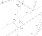
The stacked wall truss construction as shown in fig. 3 uses prefabricated wall trusses 1-4, each of which is formed from wall trusses 100 and interconnected by wall truss mating members 341 and 350. The wall truss mating members 341 and 350 may be positioned to hang from the bottom of the upper wall truss 3, 4 when the wall trusses 1, 2 and 3, 4 are joined together or to protrude from the top of the lower wall truss 1, 2 as shown in fig. 3. This enables the installation of the wall trusses 3, 4, wherein the wall trusses 3, 4 are positioned almost perfectly on top of the installed wall trusses 1, 2 below, and which also support and support the newly installed wall trusses 3, 4 immediately after installation, thereby minimizing the required crane and personnel time. Fig. 2 shows a perspective view of the mating member 132 installed in the top of the vertical column 102 of the wall truss 100. The mating member 132 is shown as being cylindrically shaped (which may be any shape, typically square or cylindrical or polygonal) and fitting inside the vertical column 102, with the floor frame 132A limiting the distance the mating member 132 enters into the vertical column 102 and also maintaining the continuity of the floor frames 111, 112. One or more lengths of rebar 132B may be inserted into the mating member 132 to provide additional strength to the wall truss 100 when the mating member 132 and vertical column 102 are filled with a filler material, such as concrete, formed as a solid mass filling the mating member 132 and vertical column 102 to create a fixed joint vertically joining adjacent wall trusses 1-4. Alternatively, if the mating member 132 is rectangular in shape, it may be welded to the vertical column 102 of the wall truss 100 to join the vertically adjacent wall trusses 1-4, or the vertically adjacent wall trusses 1-4 may be directly welded or bolted to each other.
The stacked wall truss construction enables the construction of multi-storey buildings in a highly modular manner, since in addition to the modular wall truss 100, the modular floor modules 161,162 shown in fig. 6 and 8 and the galley module 1201 shown in fig. 12 can also be efficiently constructed off the foundation in a more efficient manner and quickly incorporated into the multi-storey building as prefabricated elements. Further construction efficiencies stem from the fact that the wall enclosures and trim can be attached to the wall truss 100 prior to installation of the wall truss, and that all modules that are part of a multi-storey building can be pre-prepared with the piping and electrical subsystems, as the overall construction has been pre-planned for integrating the facility at a particular facility interconnection location as shown in fig. 12. Thus, the building construction process becomes an engineered, systematic, controlled process of preparing and installing engineered components together, wherein these components are structurally connected with connectable electrical and plumbing systems, and in many cases with pre-applied wall decoration.
Multi-storey building construction of conventional type
There are a number of conventional types of multi-storey building construction: pouring a concrete frame building; pre-casting a concrete frame building; conventional structural steel building frames; conventional wood frame buildings; and masonry construction.
Pouring a concrete frame building: in most parts of the world, it is common practice to cast concrete framed buildings on site. For each successive storey, columns are cast, beams are cast on top of the columns to join them together, and then floors are formed and cast on top of the beams and span between the beams to form a single concrete frame. Vertical and shear loads from above are transferred down through the concrete floor to the columns, beams and floor in the structure below. The structure thus exploits the great pressure resistance of concrete, using the third floor of a 20-storey building as an example, the vertical compression and shear loads associated with wind and earthquakes of the 17 storeys of this building above are taken directly on the third concrete floor and transmitted through it to the second storey below. Vertical reinforcing steel is placed which is typically erected and extended out from the column to extend through the beams and floor and into the column above to provide a vertically continuous tensile strength which concrete does not have by itself. Tensile strength is a part of the shear strength required to develop in the frame of a concrete building.
Precast concrete frame building: as a means of constructing the frame of the structure, concrete may be precast into 2D or 3D shapes. The concrete is lifted into position on the building and attached together, most commonly via welding steel that spans from an insert plate in one precast member to a similar insert in an adjacent precast member. The precast sections have the required structural capacity for vertical loading and shearing, and the connections between the precast sections also have the required structural capacity for vertical loading and shearing. The precast frame may include columns or vertical loads would be designed to be borne in the wall sections.
Conventional structural steel building frames: structural steel has enabled building construction to reach heights not previously possible. Steel is a very high strength material and has considerable strength in both tension and compression (unlike concrete which has only high compressive strength without reinforcing steel). With this high strength material, columns are conventionally provided, most commonly with significant spacing between them to create an open space on the floor without columns, and it is very important that these columns are stacked on top of each other and connected directly together. A continuous vertical load path is obtained in which the load is transferred from one column to the other through the building from top to bottom. This is quite different from a poured concrete frame in which the columns are not continuous, as each floor separates the columns from each other. Horizontal beams are provided which are attached to the columns and which support the columns, create a shear resistance in the overall frame, and support the floor by transferring the weight of the floor to the columns. As buildings become taller, the columns become larger and the beam size needs to grow to stabilize the vertical columns and create shear resistance in the overall frame of the tall building. This works well. The appearance of structural steel framed buildings and the "heavy" magnitude of column and beam framing, and the resulting ability to: building a high and wide open plan layout and creating wide open window sections in the outer wall.
A conventional wood frame: such a building shelf structure becomes common when trees are sawn into uniform size lumber. This enables the timber frame to be proliferated in areas where forests are common.
Masonry construction: masonry is perhaps one of the oldest construction techniques. Making blocks and then laying the blocks into walls is not only a historical practice but is also still a common practice in modern construction. Masonry walls are used to create load-bearing walls where the load from above is supported by masonry, and are also used in non-load-bearing constructions, such as the interior filler walls of cast concrete framed buildings. Masonry can produce relatively high compressive strength, including both brick and mortar, but (unreinforced) masonry is a low strength material in tension. Thus, there are limitations in the application of masonry construction; furthermore, masonry is laid by hand and thus inherently tends to have variability in quality and appearance.
Another difference in the type of multi-layer construction is the use of trusses. The building component is found in all four conventional types of multi-storey building construction and is further described in the next section.
Basic truss technique
From a structural perspective, the wall truss 100 may be manufactured using a support frame or a moment frame. Shear loads in the support frame are borne by the support members; shear loads in a moment frame are borne by the moment capacity of the connections between the members of the frame. In the present stacked wall truss construction, a vierendeel truss construction is used to display the wall truss 100. The basic truss technique and open web truss features are described below.
Technically, a basic truss is a structure that includes only two-force members, where the members are organized such that the assembly generally behaves as a single object. A "two-force member" is a structural component to which force is applied to only two points. Although this strict definition allows the members forming the truss to have any shape and to be interconnected in any stable configuration, the truss typically comprises five or more triangular units constructed from straight members whose ends are connected at joints known as nodes. In this typical context, external forces and reactions to external forces are considered to act only at nodes and result in tensile or compressive forces in the component. For a straight member, moments (torques) are specifically excluded because and only because all joints in the truss are considered as revolute pairs, which is necessary for the link to be a two-force member.
A conventional planar truss is one in which all of the members and nodes lie in a two-dimensional plane, while a space truss has members and nodes that extend into three dimensions. The top beams in a truss are called top chords and are usually in compression, the bottom beams are called bottom chords and are usually in tension, the inner beams are called web beams, and the area inside the web beams is called panels (panel). Trusses typically comprise straight members connected at joints, which are conventionally referred to as nodes (panel points). Trusses are generally geometric figures that do not change shape when the length of the sides is fixed, and generally include triangles because of the structural stability of the shape and design. Triangles are the simplest contrast, but for a quadrilateral to retain its shape, both the angle and the length of the quadrilateral must be fixed.
A truss may be considered a beam in which the web comprises a series of separate members rather than a continuous plate. In the truss, the lower horizontal member (bottom chord) and the upper horizontal member (top chord) are subjected to tension and compression, thereby achieving the same effect as the flanges of the I-beam. Which chord is subject to tension and which chord is subject to compression depends on the overall bending direction.
A variant of a planar truss is a vierendeel truss, which is a structure in which the members are not triangular but form rectangular openings, and is a frame with fixed joints that are able to transmit and resist bending moments. A vierendeel truss is a rigidly-joined truss having only vertical members interconnected by top and bottom chords connected to the sides of the vertical members facing adjacent vertical members and at a predetermined distance below the tops of the vertical members. The chords are generally parallel or nearly parallel. The elements in the open web truss are subject to bending, axial forces and shear, unlike conventional trusses with diagonal web members, where the members are primarily designed for axial loading. As such, it does not meet the strict definition of a truss (as it includes non-two-force members); conventional trusses comprise members that are generally assumed to have a pinned joint, meaning that there is no moment at the joint ends. The utility of this type of structure in buildings is that a large number of outer skins (envelopes) remain unobstructed and can be used for windowing as well as door openings, as shown in fig. 1 and 15. This is preferable to a support frame system that will leave some area blocked by the diagonal support.
Concrete technology
Concrete is a composite material comprising coarse aggregate bound together with fluid cement which hardens over time. Most concretes used are lime-based concretes, such as portland cement concrete or concretes made with other hydraulic cements (e.g. melts). In portland cement concrete (and other hydraulic cement concretes), when the aggregate is mixed with dry cement and water, they form a fluid mass that is easily molded into shape. The cement reacts chemically with water and other ingredients to form a hard matrix that binds all materials together into a durable stone-like material. Typically, additives (e.g., pozzolans or superplasticizers) are included in the mixture to improve the physical properties of the wet mixture or finished material. Most concrete is cast with reinforcing materials (e.g., rebar) embedded to provide tensile strength, resulting in reinforced concrete. Thus, concrete can be poured into a form (form) or column and will follow the shape of the form, hardening in place to lock the elements in the durable stone-like material.
Stacked wall truss construction
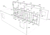
Fig. 1 and 3 show a perspective view of a wall truss 100 and a combination of vertically stacked wall trusses 1-4 one above the other, respectively, wherein the lower stacked wall truss 1 is adjacent to the vertically stacked wall truss 2 and the upper stacked wall truss 3 is adjacent to the vertically stacked wall truss 4, wherein in this figure the outer wall covering is removed to enable the steel members of the wall trusses 1-4 to be seen. In this stacked-wall truss construction, the building is actually a set of stacked structural steel trusses, without the use of separate vertically stacked columns. The design of a stacked wall truss multi-storey building results in a wall formed from vertically stacked wall trusses 1-4 rather than separate steel or concrete column frame members. The resulting multi-storey building is as follows: the plurality of wall trusses are interconnected in a three-dimensional array (matrix) to form both a plurality of multi-layered outer walls enclosing a volume of space and a plurality of internal structural partitions connected to the outer walls and together in at least two planar layers to provide lateral support to the outer walls to which they are interconnected.
In this structure, as shown in FIG. 3, each wall truss 1-4 includes a plurality of linearly aligned vertical columns 301-309, 311-319 along the horizontal length, at least two of the vertical columns in each wall truss 1-4 typically include hollow columns, and adjacent vertical columns are interconnected at the top and bottom by horizontal beams 321-327, 381-387, 351-357, 361-367. As shown in fig. 3, the wall trusses 1-4 are interconnected by using matching members 341-350, each of which can be inserted into the top end of the hollow columns of the first set of wall trusses 1, 2, wherein the matching members 341-350 protrude above the top of the hollow columns into which they are inserted and into the bottom ends of the hollow columns of the second set of wall trusses 3, 4 positioned vertically on top of the first set of wall trusses 1, 2, such that when the wall trusses 3, 4 are lifted into place by the crane, the matching members 341-350 enable the wall trusses 3, 4 to be positioned nearly perfectly on top of the installed wall trusses 1, 2 located below, and when the matching members 341-350 protrude into the wall truss columns 311-319 above and the wall truss columns 301-309 below to such an extent that the installed wall trusses 3, 4 will not fall down, the mating members 341 and 350 also immediately hold the installed wall trusses 3, 4 in place. It is immediately stable when the wall truss is put down in place and the positioning is perfect and effortless. In addition, floor frames 331-337 are inserted between the wall trusses 1-4. All the wall trusses 1-4 are manufactured with precise dimensional consistency, so that the assembly is reliable and simple, with identical pieces aligned with each other. It is therefore the wall trusses 1-4 that are stacked rather than individual columns, unlike conventional structural steel designs and constructions. Furthermore, the wall thickness of the vertical column may vary with its position in a multi-storey building, where the upper floors of the building require a lighter wall material, since the loads experienced at that location are reduced compared to the loads experienced at the lower floors. As described in more detail below, the wall truss columns 305, 306, 315, and 316 of the ends of the illustrated wall trusses 1, 2 and 3, 4 may be attached together by means of welding, pinning, bolting, strapping, concrete infill, and/or other means.
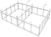
A set of sequential images showing a construction method using the wall truss of the present invention includes fig. 4, 5 and 6: fig. 4 shows a perspective view of an installation arrangement for a wall truss of two apartments, with a floor frame installed near the top of the upper wall truss; FIG. 5 illustrates a perspective view of a group of wall trusses with floor modules in a typical multi-storey building using the stacked wall truss construction design and construction method for a multi-storey building of the present invention; fig. 6 shows a perspective view of a set of wall trusses in a typical multi-storey building ready to receive floor modules to be placed on floor frames using the stacked wall truss construction design and construction method for a multi-storey building of the present invention.
As shown in fig. 4, the wall trusses may be interconnected to form two enclosed spaces A, B; and this form can be expanded in three dimensions to form a multi-layer framework as shown in fig. 5. The base wall truss spaces A, B may be combined with a matching set of enclosed spaces C, D added to the top thereof to form a two-tiered framework. The wall truss space A, B includes a floor rack as described above and shown in fig. 5 on which floor modules are placed to provide a floor for the wall truss space C, D. A corresponding set of two-tiered wall truss spaces E-H can be positioned juxtaposed to the wall truss spaces a-D, separated from the wall truss spaces a-D by a common area space J. This structure is shown in a further completed form in fig. 14 and 15 described below.
Floor module
Fig. 6 and 7 show details of the floor modules 161, 162. Each floor module such as 161 includes a plurality of parallel oriented spaced apart floor joists such as floor joists 164 having a plurality of cutouts 164A (fig. 7) formed therein through which utilities may be routed. The floor modules 161,162 are supports for floor panels 161A, 162A that provide a base for flooring material (flooring), such as a top panel 1031 (shown in fig. 10). Fig. 6 also shows that a foundation wall 170, 171 is provided having embedded therein a foundation embedded plate bolt on top of which is attached a mating member, as described below (collectively referred to herein as "mating anchor"). The floor modules 161,162 and their respective floor panels 161A, 162A are mounted on floor racks of the enclosed space A, B.
Figure 7 shows additional detail of the floor module 161 with the floor panel 161A partially cut away to expose the floor joists 164. The floor joists 164 are capped at their ends by capping rails 171, 172 that are interconnected at their ends with floor joists 173, 174 that do not have any openings formed therein. Thus, the elements 171-174 create a solid peripheral surface frame for the floor module 161 to enable a top plate 1031 (shown in fig. 10) to be poured on top of the floor panel 161A and to extend into the space between the floor module 161 and the surrounding wall truss as described below. Various utilities are installed in the floor modules 161 by routing between adjacent floor joists 164 and through openings 164A formed in the floor joists 164. Electrical service facilities 167, 168 are shown, as are water and waste conduits 165, 166. These facilities are all routed to one side of the floor module 161, where the facilities are presented at openings 169A, 169B, where each opening provides access to a group of facilities. Fig. 8 shows an enlarged view of the openings 169A, 169B and the respective ducts 165, 166 and electrical service facility 167, 168 facility interconnects.
Fig. 9 is a sectional view of an outer wall of a multistory building in which the wall truss 3 is installed on top of the wall truss 1. The wall trusses 1, 3 include vertical columns 303, 311 interconnected by mating members having floor frames 1021 segments. The horizontal members 1051, 1052 are shown in cross-section for illustrative purposes. The second and first outer wall plates 1042, 1041 are attached to the wall trusses 1, 3, respectively. The second fascia panel 1042 is secured in place on its top side by a depending portion of the floor frame 1021, which turns in a downward direction. The underside of each first outer wall panel 1041 is secured by a boss/wall recess 921. The space between the respective first and second outer wall panels 1041, 1042 may be filled by applying a filler material, which provides protection from the elements. On the inner side of the wall trusses 1, 3, wall coverings 1011, 1012 are fastened to the vertical columns 311, 301 in a conventional manner.
Floor cross section
Figure 10 shows a cross-section at the joint between two sets of typical stacked wall trusses 1-3 and 1003-1004. Further, fig. 10 shows a top plate 1031 that is poured on top of the floor module 161 and also fills the gap (fluid receiving recess) between the edges of the floor frames 1021, 1022 and the wall trusses 1, 1003. Fig. 10 also shows the thin concrete first and second exterior wall panels 1041, 1042 used in the preferred embodiment, where the thin concrete first and second exterior wall panels 1041, 1042 are attached to the wall trusses 3, 1 before the wall trusses 3, 1 are installed on the building, where the first and second exterior wall panels 1041, 1042 are in an exterior condition on the outside of the wall trusses 3, 1, and the thin concrete wall panels 1013 and 1016 are used on the wall trusses 3, 1, 1003, 1004, where the thin concrete wall panels 1013 and 1016 serve as an internal separator for fire and sound insulation as needed in a multi-storey building.
Due to the limited space available in the figure, fig. 10 also shows, for clarity, only a part of the wall trusses 1, 3, 1003, 1004 and the cooperating components. The wall trusses 1, 3 each comprise a wall truss column such as 301, 311 respectively, in the case of the wall truss columns 311, 301, first 1041 and second 1042 outer wall panels are attached to the wall truss columns 311, 301 as exterior trim of the building. The wall truss columns 311, 301 are interconnected to their respective adjacent wall truss columns (not shown) via two horizontal wall truss beams, two 1051 and 1052 of which are shown in fig. 10 respectively (also the horizontal wall truss beams 1053, 1054 for the wall trusses 1003, 1004 are shown). In order for the structure to support the floor, floor frames 1021, 1022 are attached to the horizontal wall truss beams 1052 and 1054, respectively, by welding, bolting, or some other structural connection to receive the floor module 161, which is a floor load bearing element between the facing floor frames 1021, 1022. The floor frames 1021 extend the length of the wall truss 1. The floor modules 161 as shown in fig. 6 and 7 are placed on top of the floor frames 1021, 1022 and span the opening between the walls formed by the wall trusses 1, 3, 1003, 1004. The floor module 161 includes a plurality of generally parallel oriented floor joists 164 on top of which is placed a deck (deck) 161A that provides a solid surface onto which the top plate 1031 may be poured. In this case, a thin top plate 1031 of concrete is poured on top of the deck 161A, and this top plate 1031 also fills the space between the floor module 161 and the wall trusses 3, 1003. The floor module 161 shown in the preferred embodiment of fig. 6, 7 and 10 is framed with a light gauge steel floor joist 164 spanning in one direction and capping rails 171, 172 that cap and surround the ends of the floor joists 164 in the floor module 161 on both sides of the floor module 161 with the ends of the light gauge joists. The top plate 1031 also fills the void between the wall trusses 3 and 1003 and other similar locations because the cover rails 171, 172 and end joists 173, 174 and floor frames 1021, 1022 form recesses into which concrete poured for the top plate 1031 can flow to create an integral structure (floor plate anchors) that lock the floor module 161 to the wall trusses 3, 1003. The concrete top plate 1031 may be decorated to become the final interior decoration or may be a subfloor for carpet or floor tile or wood flooring materials, or the like. The deck 161A is supported by the floor module 161 and a concrete floor trim top plate 1031 is applied thereto. When the wall trusses are attached to each other horizontally and vertically to stabilize them in three dimensions, and the top plate 1031 is poured to further attach the wall trusses 3, 1003 together and also structurally integrate the floor module 161 with all the wall trusses 3, 1003, a structurally integrated assembly is created in which all the coordinated assemblies are structurally interconnected and serve as a structural whole.
Fig. 13 shows a typical galley module for a galley that includes a cooktop/range hood 1305, a sink 1306, cabinets 1301-. The facilities 1310, 1311 serving these appliances extend to interconnection points in the appliance module 1300, which facilities match the facilities pre-installed in the floor module 161 as disclosed above. Interconnection of the facilities 1310, 1311 may be done after installation of the top plate 1031, which simplifies construction of the trim in the dwelling unit.
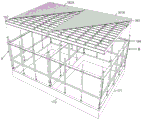
Roof with a plurality of layers of material
Fig. 12 illustrates a typical roof installation including a conventional parallel oriented set of roof joists 1221, shown with the roof covering 1222 partially removed. The roof may be attached to the top floor of a multi-storey building using conventional techniques to connect to the wall truss 1201-1204 and its floor modules 1211-1213 and may be of any type and decoration.
In the multi-storey residential building application described herein, figure 14 shows two apartment units and their respective walls. The walls each comprise five wall truss columns, respectively, which are interconnected by pairs of wall truss beams, respectively. In a similar manner, the walls each comprise five wall truss columns, respectively, which are interconnected by pairs of wall truss beams, respectively. The plan view shows the position of the wall truss beam, which in practice is two chords per span, one chord at the top and one chord at the bottom of the wall truss column, as illustrated in fig. 5.
Foundation
Fig. 11A-11F illustrate a mechanism that can be used to convert from conventional cast concrete foundations 170 and 171 (in fig. 6) of a multi-story building to a precisely dimensioned framing system that must rely on and attach to cast-in-place concrete. It is almost impossible to precisely control the resulting finished dimensions of the concrete cast in situ or the insert cast into the concrete. The precise dimensions of the wall truss require a corresponding accuracy at the attachment point of the wall truss to the foundation at each wall truss column. Welded panels are typically embedded in cast-in-place concrete as attachment points for later stages of construction. Fig. 11 shows an anchor member comprising a novel weld plate 1111A which has been drilled in the centre, a threaded steel rod 1111B or bolt is attached to the weld plate 1111A with the threaded portion of the rod 1111B extending upwards. In this configuration, the weld plate 1111A with the threaded rod 1111B attached thereto may be embedded in the concrete during casting, and the embedded nails securely fasten the weld plate 1111A with the threaded bolt 1111B. To easily correct any misalignment, the mating member 1111C may have a flat plate 1111Q welded to one end, the flat plate having a hole therein. The hole may be 13/8 inches and the threaded rod may be 3/8 inches. If the wand is in the ideal position, the wand will be centered in the hole, creating a full circle of uniform gap of the same inches around the wand. However, the threaded rod can be moved away from this position by up to, and the following would be simple and easy: the mating member 1111C is slid into place and then attached with a large washer and nut 1111D and possibly subsequently welded to the weld plate 1111A. An ideal starting point for a precise wall truss is obtained.
The difference between the present stacked wall truss construction and the prior art is the design and construction of the floor and horizontal components of the building frame. The prior art structural steel frame has generally horizontal beams that frame into individual steel columns, whereas the present stacked-wall truss construction does not. By placing the vertical wall trusses in an orthogonal arrangement, the vertical wall truss columns of the wall trusses that are perpendicular to each other are attached together, thereby preventing each wall truss from "falling down" in the opposite direction relative to its plane. Thus, unlike conventional structural steel building constructions that require heavy steel beams to constrain horizontal movement of individual steel columns and to provide shear resistance to the frame, the geometric configuration of the stacked wall truss construction of orthogonally positioned vertical wall trusses that would otherwise occur in plan view inherently controls and stabilizes wall truss column movement that is connected at their ends and on wall truss columns that are not on the ends. Therefore, it is not necessary to use heavy steel beams or conventional separate column/beam structures to create a support frame or special moment frame (special moment frame). Instead, a spread of smaller wall truss columns (as small as 6 "x 6" in a 14-storey building) is created and a spread of shear elements is created by means of a large number of wall trusses, each providing a shear resistance extending in two planar directions, without the creation of a shear resistance in a conventional individual steel column/beam frame, resulting in a sufficient level of total shear resistance.
Also distinguished is the installed floor, which is a light gauge steel or joist type floor module pre-assembled into a conforming assembly that rests on top of the floor frame near the top of the wall truss. The floor rack is a carrier for the floor module. Thus when the wall truss is installed on a specific floor of a building, a continuous floor rack has been created in the hallway, room, apartment unit and outdoor balcony area so that the floor modules of the prefabricated hallway, room, apartment unit and outdoor balcony area can be lifted with a crane (where these prefabricated floor modules are placed close to the crane for assembly) and put down into place quickly and efficiently. No connection to the building frame needs to be made before the crane can be released, since the floor modules are merely placed on the floor frames and do not need to be positioned accurately. These floor modules are all placed on the peripheral floor frame of a given building area and typically provide clearance on side 4 to enable easy positioning of the floor modules, so only the floor modules are lowered onto the floor frame and proceed. Thereafter, the floor modules may be moved manually or otherwise a little bit in one direction or the other, one or two inches, as needed to achieve the desired alignment. This requires little skill and is difficult to install by mistake. A concrete top slab is then poured on top of the floor module to create a fire-resistant, sound-insulating structural membrane that can also be finished into the finished floor surface. The resulting floor is implemented without the thick concrete slab that can span across a room as found in conventional cast-in-place concrete buildings, and also without the heavy separate steel column/beam framework as in conventional structural steel construction.
From the structural steel design point of view, the wall truss may be a "support frame" or a "moment frame or special moment frame". As a support frame, diagonal members of steel or other support members are installed in at least one bay (bay) of each wall truss. The diagonal lines act as shear supports in the wall truss, greatly increasing its ability to resist folding in the direction of the wall truss. A special moment frame is created when, by means of the geometry of the wall truss and its members and their connection together only, the wall truss has a shear resistance to collapse in the direction of the wall truss and to act with the inherent shear resistance of the open web truss. Moment frames flex during cyclic loading of earthquakes and during wind loading, as opposed to frames that are merely rigidly supported; thus, moment frames tend to perform better and are preferred in high multi-storey buildings and high seismic load areas. Both embodiments work and the architecture and design engineering in the art can be either.
The thin concrete panels of the preferred embodiment of the multi-storey building are cast on the prefabricated wall truss in the on-site forming system or they are manufactured as another prefabricated component which is simply attached to the wall truss. Either way, in a preferred embodiment in the art, when the wall truss is lifted, it includes structural elements, installed facilities, wall and wall decorations, and the like. There is no need to return to placing manually laid bricks as an internal filler as is done today in conventional cast-in-place concrete buildings. The method comprises the steps of lifting the wall truss, placing floor modules, casting a roof, connecting facilities that have been pre-installed in the modular elements at the facility interconnection locations, and then proceeding forward and upward.
Figure 14 shows a plan view of one storey of a partially completed multi-storey building using stacked prefabricated structural steel walls; FIG. 6 shows a perspective view of a plurality of typical residential apartments of a multi-storey building constructed using a stacked-wall truss construction; and figure 15 shows a typical completed multi-storey building using a stacked wall truss construction. These figures provide an overview of the construction and appearance of a multi-storey building. In particular, the perspective view of figure 6 shows the layout of two typical residential apartment units with the final trim element installed therein. In fig. 5, the two residential apartment units are shown in their basic exterior wall stage, where the walls and floor have been placed by the crane on site on top of the second floor of the partially completed multi-storey building. As the construction progresses, successive floors are added until the multi-storey building is completed, as shown in fig. 7.
Summary of the invention
The present stacked wall truss construction and its use in the construction of a multi-storey building thus departs from the conventional method of constructing a multi-storey building: prefabricated modular wall trusses are used which are interconnected in three dimensions to enable building construction to be completed quickly with improved construction quality compared to that seen in conventional multi-storey building construction. Furthermore, additional modular elements including floor modules and galley modules supplement the wall truss to create a fully modular procedure for building construction that can be accomplished quickly and efficiently. The resulting building is effectively a structural steel framework that does not use conventional, heavy, individual stacked columns and beams, because the vertical wall truss creates smaller continuous vertical steel elements by virtue of the design construction and vertical assembly of the wall truss, whereby the building construction becomes a process of stacking the wall truss rather than individual heavy steel columns and beams. The internal wall truss column mating members may be placed to hang out from the bottom of each wall truss or to protrude from the top of the lower wall truss so that the wall truss placement can be almost perfectly positioned on top of the wall truss installed below.
Claims (20)
1. A method for constructing a multi-storey building having floor frames for supporting a floor, the method comprising:
assembling a plurality of wall trusses, wherein each wall truss comprises a moment frame comprising a plurality of vertical members, adjacent ones of which are interconnected at the top and bottom by horizontal beams spanning the space between adjacent vertical members and connected to respective sides of the vertical members, the interconnections being fixed joints, wherein at least two vertical members of the wall truss comprise hollow columns;
for at least two floors of the multi-storey building:
placing a floor frame on a top horizontal beam of a wall truss, wherein the floor frame includes a substantially planar surface extending into an interior of the multi-storey building in a horizontal direction perpendicular to the top horizontal beam;
stacking additional wall trusses on top of the plurality of wall trusses installed for the lower floors,
inserting mating members into the hollow columns of at least two of the vertical members of each wall truss and additional wall truss, wherein the mating members extend into both the hollow column of each wall truss and the hollow column of the additional wall truss;
disposing a floor module on top of the floor frame to span a distance between the facing wall trusses; and
pouring floor slabs on top of the floor modules to cover the spaces between the facing wall trusses;
wherein the fixed joint is capable of transmitting and resisting bending moments.
2. The method for constructing a multi-storey building having floor frames for supporting a floor as claimed in claim 1 wherein the step of casting the floor panels further comprises:
extending the floor slab into the wall truss to enclose the vertical members of the facing wall truss in the floor slab.
3. The method for constructing a multi-storey building having floor frames for supporting a floor as claimed in claim 1 wherein the floor modules include capping rails attached to each side of the floor modules to create a fluid receiving recess between the floor modules and the facing wall trusses, the step of casting the floor slab further comprising:
extending the floor slab into the fluid receiving recess to join the floor module with the facing wall truss.
4. The method for constructing a multi-storey building having a floor frame for supporting a floor as claimed in claim 1, the method further comprising:
attaching a wall panel to an exterior surface of each wall truss, the wall truss forming a portion of an exterior wall of the multi-storey building; and
wherein, the step of pouring the floor plate body further comprises:
extending the floor slab into the wall trusses to the attached wall panels to enclose the vertical members of each wall truss in the floor slab, the wall trusses forming part of the exterior walls of the multi-storey building.
5. The method for constructing a multi-storey building having a floor frame for supporting a floor as claimed in claim 1 wherein the step of providing a floor module comprises:
a plurality of floor joists are positioned at predetermined intervals along the length of the floor frame to span a distance between facing wall trusses into the interior of the multi-storey building.
6. The method for constructing a multi-storey building having a floor frame for supporting a floor as claimed in claim 5 wherein the step of providing a floor module further comprises:
floor panels are installed on top of the plurality of floor joists to cover the space between the facing wall trusses.
7. The method for constructing a multi-storey building having a floor frame for supporting a floor as claimed in claim 5 wherein the step of providing a floor module further comprises:
attaching a capping rail to an end of the floor joist to surround a side of the floor module to create a fluid receiving recess between the floor module and the facing wall truss.
8. The method for constructing a multi-storey building having floor frames for supporting a floor as claimed in claim 7 wherein the step of casting the floor panels further comprises:
extending the floor slab into the fluid receiving recess to join the floor module with the facing wall truss.
9. The method for constructing a multi-storey building having a floor frame for supporting a floor as claimed in claim 1, the method further comprising:
the vertical members of the pre-constructed set of wall trusses are welded to their mating vertical members to create a fixed joint.
10. The method for constructing a multi-storey building having a floor frame for supporting a floor as claimed in claim 1, the method further comprising:
the mating member and the hollow post into which it is inserted are filled with a predetermined amount of material formed into a solid block to create a fixed joint.
11. A multi-storey building having a floor frame for supporting a floor, the multi-storey building comprising:
a plurality of wall trusses interconnected in a three dimensional array to form both a plurality of multi-layered outer walls enclosing a volume of space and a plurality of internal structural partitions connected to the outer walls in at least two planar layers and connected together to provide lateral support to the outer walls to which they are interconnected;
characterized in that each of the wall trusses comprises a moment frame comprising a plurality of vertical members, adjacent vertical members of the plurality of vertical members being interconnected at the top and bottom by horizontal beams spanning the space between adjacent vertical members and connected to respective sides of the vertical members, the interconnection being a fixed joint, wherein at least two vertical members of the wall truss comprise hollow columns;
wherein at least two floors of the multi-storey building comprise:
floor frames mounted on the top horizontal beams of the wall trusses, each floor frame including a generally planar surface extending into the interior of the multi-storey building in a horizontal direction perpendicular to the top horizontal beams of the wall trusses;
wall truss mating members, each insertable into a top end of a hollow column of a first wall truss and insertable into a bottom end of a hollow column of a second wall truss positioned vertically on top of the first wall truss;
an additional wall truss stacked on top of a plurality of wall trusses installed for a lower floor, the bottom of the hollow column of the vertical members of a set of wall trusses being disposed over the protruding top of the mating members of the vertical members of the existing wall trusses of the lower floor;
a floor module disposed on top of the floor frame to span a distance between the facing wall trusses; and
a floor slab extending between the inner surfaces of the wall trusses and poured over the top of the floor module to cover the space between the facing wall trusses;
wherein the fixed joint is capable of transmitting and resisting bending moments.
12. The multi-storey building having floor frames for supporting a floor of claim 11, wherein the floor panel further comprises:
a floor panel anchor extending into the wall truss to enclose the vertical members of the wall truss in the floor panel.
13. The multi-storey building with floor frames for supporting a floor of claim 11 further comprising:
a cover rail attached to each side of the floor module to create a fluid receiving recess between the floor module and the facing wall truss; and is
Wherein, the floor plate body still includes:
a floor panel anchor formed in the fluid-receiving recess to couple the floor module with a juxtaposed wall truss.
14. The multi-storey building with floor frames for supporting a floor of claim 10 further comprising:
a wall panel attached to an outer surface of each wall truss, the wall truss forming a portion of an outer wall of the multi-storey building; and
wherein, the floor plate body still includes:
a floor panel anchor formed in the wall truss and extending to an attached wall panel to enclose the vertical members of the wall truss in the floor panel.
15. The multi-storey building with floor frames for supporting a floor of claim 11, wherein the floor module comprises:
a plurality of floor joists positioned at predetermined intervals along the length of the floor frame to span a distance between facing wall trusses into the interior of the multi-storey building.
16. The multi-storey building with floor frames for supporting a floor of claim 15, wherein the floor module comprises:
a floor panel mounted on top of the plurality of floor joists to cover a space between the facing wall trusses.
17. The multi-storey building with floor frames for supporting a floor of claim 15, wherein the floor module further comprises:
a cover rail attached to an end of the floor joist to enclose a side of the floor module to create a fluid receiving recess between the floor module and a juxtaposed wall truss.
18. The multi-storey building with floor frames for supporting a floor of claim 17, wherein the floor panel further comprises:
a floor panel anchor extending into the fluid receiving recess to couple the floor module with the facing wall truss.
19. The multi-storey building with floor frames for supporting a floor of claim 11 further comprising:
a weldment for interconnecting the vertical members of the pre-constructed set of wall trusses to their mating members to create a fixed joint.
20. The multi-storey building with floor frames for supporting a floor of claim 11 further comprising:
a predetermined amount of material formed into a solid block filling the mounting member and hollow post to create a fixed joint.
Applications Claiming Priority (3)
| Application Number | Priority Date | Filing Date | Title |
|---|---|---|---|
| US201662298054P | 2016-02-22 | 2016-02-22 | |
| US62/298054 | 2016-02-22 | ||
| PCT/US2017/013902 WO2017146838A1 (en) | 2016-02-22 | 2017-01-18 | Method for constructing multi-story buildings using stacked structural steel wall trusses |
Publications (2)
| Publication Number | Publication Date |
|---|---|
| CN109072604A CN109072604A (en) | 2018-12-21 |
| CN109072604B true CN109072604B (en) | 2021-09-28 |
Family
ID=57944552
Family Applications (4)
| Application Number | Title | Priority Date | Filing Date |
|---|---|---|---|
| CN201780012781.8A Expired - Fee Related CN108779634B (en) | 2016-02-22 | 2017-01-18 | Construction of multi-storey buildings using stacked structural steel wall trusses |
| CN201780012843.5A Expired - Fee Related CN108779636B (en) | 2016-02-22 | 2017-01-18 | Stacking structure steel wall truss |
| CN201780012803.0A Expired - Fee Related CN109072604B (en) | 2016-02-22 | 2017-01-18 | Method for constructing multi-storey building using stacked structural steel wall truss |
| CN201780012812.XA Expired - Fee Related CN108779635B (en) | 2016-02-22 | 2017-01-18 | Method for constructing multi-storey building using stacked structural steel wall truss |
Family Applications Before (2)
| Application Number | Title | Priority Date | Filing Date |
|---|---|---|---|
| CN201780012781.8A Expired - Fee Related CN108779634B (en) | 2016-02-22 | 2017-01-18 | Construction of multi-storey buildings using stacked structural steel wall trusses |
| CN201780012843.5A Expired - Fee Related CN108779636B (en) | 2016-02-22 | 2017-01-18 | Stacking structure steel wall truss |
Family Applications After (1)
| Application Number | Title | Priority Date | Filing Date |
|---|---|---|---|
| CN201780012812.XA Expired - Fee Related CN108779635B (en) | 2016-02-22 | 2017-01-18 | Method for constructing multi-storey building using stacked structural steel wall truss |
Country Status (13)
| Country | Link |
|---|---|
| US (4) | US10577793B2 (en) |
| EP (4) | EP3420154B1 (en) |
| JP (4) | JP6946349B2 (en) |
| KR (4) | KR20180115735A (en) |
| CN (4) | CN108779634B (en) |
| AU (4) | AU2017222254A1 (en) |
| BR (4) | BR112018017096A2 (en) |
| CA (4) | CA3014756A1 (en) |
| ES (4) | ES2796730T3 (en) |
| MX (3) | MX2018010070A (en) |
| PH (4) | PH12018501752A1 (en) |
| SA (4) | SA518392232B1 (en) |
| WO (4) | WO2017146838A1 (en) |
Families Citing this family (13)
| Publication number | Priority date | Publication date | Assignee | Title |
|---|---|---|---|---|
| US10508432B2 (en) * | 2018-04-24 | 2019-12-17 | Ss-20 Building Systems, Inc. | Connection for stacking post system for multistory building construction |
| CN108643347B (en) * | 2018-04-27 | 2020-11-24 | 长江大学 | Steel reinforced concrete frame-reinforced concrete wallboard mixed structure system |
| MY190872A (en) * | 2018-07-09 | 2022-05-13 | Yau Lee Wah Concrete Precast Products Shenzhen Company Ltd | Modular integrated building and construction method thereof |
| CN109440923A (en) * | 2018-12-17 | 2019-03-08 | 贵州大学 | A kind of irregular honeycomb space lattice box structure and production method |
| KR102092608B1 (en) * | 2019-03-21 | 2020-03-25 | 주식회사 썬앤라이트 | Smart modular |
| CA3145826A1 (en) * | 2019-07-15 | 2021-01-21 | Intelligent City Inc. | Facade panel with integrated window system |
| CN110565800A (en) * | 2019-09-16 | 2019-12-13 | 青岛理工大学 | Assembly node module, integrated construction system and integrated construction method |
| US11421418B2 (en) | 2019-12-20 | 2022-08-23 | Universal City Studios Llc | Truss with integrated wiring |
| US11692341B2 (en) | 2020-07-22 | 2023-07-04 | Nano And Advanced Materials Institute Limited | Lightweight concrete modular integrated construction (MIC) system |
| EP4225999A1 (en) | 2020-10-06 | 2023-08-16 | Charles Joseph EL KHOURY | Modular panels and system for using said panels |
| US20240026676A1 (en) * | 2020-10-22 | 2024-01-25 | Innovative Building Technologies, Llc | Multi-story building having load bearing walls and method to construct the building |
| CN114033221B (en) * | 2021-11-05 | 2023-09-12 | 中建海龙科技有限公司 | Steel structure house box and production process thereof |
| CN114232843B (en) * | 2021-12-16 | 2023-08-08 | 中建五局第三建设有限公司 | Fully assembled building and construction method thereof |
Family Cites Families (28)
| Publication number | Priority date | Publication date | Assignee | Title |
|---|---|---|---|---|
| US1174724A (en) * | 1914-04-07 | 1916-03-07 | Hans Honigmann | Automatic feeding device for platen printing-presses. |
| FR1174724A (en) * | 1957-04-26 | 1959-03-16 | Prefabricated sub-assembly for buildings and other constructions and assemblies with application | |
| US5012622A (en) * | 1985-03-05 | 1991-05-07 | Shimizu Construction Co., Ltd. | Structural filler filled steel tube column |
| JPS62160337A (en) * | 1985-12-28 | 1987-07-16 | 清水建設株式会社 | Unbond filled steel pipe structure |
| JP3234398B2 (en) * | 1994-04-01 | 2001-12-04 | 新日本製鐵株式会社 | Steel pipe joint structure |
| JPH08311991A (en) * | 1995-05-17 | 1996-11-26 | Taisei Corp | Connection method of steel pipe column |
| JPH094052A (en) * | 1995-06-21 | 1997-01-07 | Sekisui Chem Co Ltd | Joint structure for column capital and column base, column base footing joint structure, and unit building |
| JPH09317003A (en) * | 1996-05-28 | 1997-12-09 | Shimizu Corp | Steel pipe column |
| JP3121557B2 (en) * | 1997-03-14 | 2001-01-09 | ミサワホーム株式会社 | Building units and unit buildings |
| JP4186371B2 (en) * | 2000-02-17 | 2008-11-26 | Jfeスチール株式会社 | Connecting structure of beams and joists |
| US6625937B1 (en) * | 2000-12-27 | 2003-09-30 | Sunrise Holding, Ltd. | Modular building and method of construction |
| JP2004316278A (en) * | 2003-04-17 | 2004-11-11 | Maeda Corp | Structure of steel pipe plinth part |
| JP4748637B2 (en) * | 2003-08-29 | 2011-08-17 | 株式会社サトコウ | Building unit joint structure |
| US8234827B1 (en) * | 2005-09-01 | 2012-08-07 | Schroeder Sr Robert | Express framing building construction system |
| JP2008190261A (en) * | 2007-02-06 | 2008-08-21 | Ysc:Kk | Building |
| JP2009062717A (en) * | 2007-09-06 | 2009-03-26 | Union Kenzai Builder:Kk | Fixing structure of column base section, steel-pipe column material, and panel body equipped with the steel-pipe column material |
| US8661755B2 (en) * | 2008-01-24 | 2014-03-04 | Nucor Corporation | Composite wall system |
| CN101265723B (en) * | 2008-05-07 | 2012-08-15 | 北京太空板业股份有限公司 | Architecture structure system assembled by composite building board and building method |
| CN101368428B (en) * | 2008-07-18 | 2011-07-20 | 徐尉 | Prefabricated component house and its construction method |
| EP2513384B1 (en) * | 2009-12-18 | 2016-09-21 | Patco LLC | Panelized structural system for building construction |
| US8720154B1 (en) | 2010-06-17 | 2014-05-13 | James P. Horne | Cold-formed steel structural wall and floor framing system |
| CN201952898U (en) * | 2010-09-06 | 2011-08-31 | 北京诚栋国际营地集成房屋有限公司 | Detachable and movable dwelling with single layer of flat roof |
| JP5755458B2 (en) * | 2011-01-31 | 2015-07-29 | 旭化成ホームズ株式会社 | Deck plate panel and floor structure using the same |
| US20120240482A1 (en) * | 2011-03-22 | 2012-09-27 | XSite Modular | Components for a Modular High-Rise Structures And Method For Assembling Same |
| SG11201402089UA (en) | 2011-12-14 | 2014-06-27 | Marion Invest Ltd | Apparatus, systems and methods for modular construction |
| CN103382741B (en) * | 2013-06-27 | 2016-05-25 | 张建忠 | A kind of fixed connection structure of prefabricated board |
| WO2016009411A1 (en) * | 2014-07-17 | 2016-01-21 | Sistemas De Construcción Industrial S.A.S. – Sisdeco | Adaptable industrial construction system with natural air-conditioning |
| CN104314201A (en) * | 2014-11-17 | 2015-01-28 | 菏泽霸王机械有限公司 | Composite thermal insulating wall of light steel structure |
-
2017
- 2017-01-18 CA CA3014756A patent/CA3014756A1/en not_active Abandoned
- 2017-01-18 AU AU2017222254A patent/AU2017222254A1/en not_active Abandoned
- 2017-01-18 CN CN201780012781.8A patent/CN108779634B/en not_active Expired - Fee Related
- 2017-01-18 KR KR1020187026727A patent/KR20180115735A/en unknown
- 2017-01-18 BR BR112018017096A patent/BR112018017096A2/en not_active Application Discontinuation
- 2017-01-18 BR BR112018017083A patent/BR112018017083A2/en not_active Application Discontinuation
- 2017-01-18 ES ES17702486T patent/ES2796730T3/en active Active
- 2017-01-18 ES ES17704121T patent/ES2809717T3/en active Active
- 2017-01-18 US US16/076,692 patent/US10577793B2/en not_active Expired - Fee Related
- 2017-01-18 KR KR1020187026728A patent/KR20180115736A/en unknown
- 2017-01-18 CA CA3014783A patent/CA3014783A1/en not_active Abandoned
- 2017-01-18 KR KR1020187026730A patent/KR20180115737A/en unknown
- 2017-01-18 US US16/076,691 patent/US10577792B2/en not_active Expired - Fee Related
- 2017-01-18 JP JP2018562503A patent/JP6946349B2/en active Active
- 2017-01-18 WO PCT/US2017/013902 patent/WO2017146838A1/en active Application Filing
- 2017-01-18 WO PCT/US2017/013893 patent/WO2017146836A1/en active Application Filing
- 2017-01-18 ES ES17702487T patent/ES2795873T3/en active Active
- 2017-01-18 CA CA3015699A patent/CA3015699A1/en not_active Abandoned
- 2017-01-18 WO PCT/US2017/013903 patent/WO2017146839A1/en active Application Filing
- 2017-01-18 EP EP17704121.7A patent/EP3420154B1/en active Active
- 2017-01-18 AU AU2017222253A patent/AU2017222253A1/en not_active Abandoned
- 2017-01-18 JP JP2018562504A patent/JP6946350B2/en active Active
- 2017-01-18 JP JP2018562502A patent/JP6946348B2/en active Active
- 2017-01-18 KR KR1020187026731A patent/KR20180115738A/en unknown
- 2017-01-18 CN CN201780012843.5A patent/CN108779636B/en not_active Expired - Fee Related
- 2017-01-18 BR BR112018017093A patent/BR112018017093A2/en not_active Application Discontinuation
- 2017-01-18 BR BR112018017006-2A patent/BR112018017006A2/en not_active Application Discontinuation
- 2017-01-18 EP EP17702486.6A patent/EP3420151B1/en active Active
- 2017-01-18 CN CN201780012803.0A patent/CN109072604B/en not_active Expired - Fee Related
- 2017-01-18 EP EP17702487.4A patent/EP3420152B1/en active Active
- 2017-01-18 US US16/076,689 patent/US10584485B2/en not_active Expired - Fee Related
- 2017-01-18 EP EP17702720.8A patent/EP3420153B1/en active Active
- 2017-01-18 WO PCT/US2017/013894 patent/WO2017146837A1/en active Application Filing
- 2017-01-18 CN CN201780012812.XA patent/CN108779635B/en not_active Expired - Fee Related
- 2017-01-18 US US16/076,688 patent/US10584484B2/en not_active Expired - Fee Related
- 2017-01-18 MX MX2018010070A patent/MX2018010070A/en unknown
- 2017-01-18 AU AU2017222252A patent/AU2017222252A1/en not_active Abandoned
- 2017-01-18 CA CA3014758A patent/CA3014758A1/en not_active Abandoned
- 2017-01-18 AU AU2017222255A patent/AU2017222255A1/en not_active Abandoned
- 2017-01-18 JP JP2018562501A patent/JP2019509414A/en active Pending
- 2017-01-18 MX MX2018010069A patent/MX2018010069A/en unknown
- 2017-01-18 ES ES17702720T patent/ES2809715T3/en active Active
- 2017-01-18 MX MX2018010068A patent/MX2018010068A/en unknown
-
2018
- 2018-08-16 SA SA518392232A patent/SA518392232B1/en unknown
- 2018-08-16 SA SA518392231A patent/SA518392231B1/en unknown
- 2018-08-16 SA SA518392237A patent/SA518392237B1/en unknown
- 2018-08-17 PH PH12018501752A patent/PH12018501752A1/en unknown
- 2018-08-17 PH PH12018501755A patent/PH12018501755A1/en unknown
- 2018-08-17 PH PH12018501754A patent/PH12018501754A1/en unknown
- 2018-08-17 PH PH12018501753A patent/PH12018501753A1/en unknown
- 2018-08-19 SA SA518392249A patent/SA518392249B1/en unknown
Also Published As
Similar Documents
| Publication | Publication Date | Title |
|---|---|---|
| CN109072604B (en) | Method for constructing multi-storey building using stacked structural steel wall truss | |
| EP1992750A1 (en) | Prefabricated reinforced-concrete single-family dwelling and method for erecting said dwelling |
Legal Events
| Date | Code | Title | Description |
|---|---|---|---|
| PB01 | Publication | ||
| PB01 | Publication | ||
| SE01 | Entry into force of request for substantive examination | ||
| SE01 | Entry into force of request for substantive examination | ||
| GR01 | Patent grant | ||
| GR01 | Patent grant | ||
| CF01 | Termination of patent right due to non-payment of annual fee |
Granted publication date: 20210928 Termination date: 20220118 |
|
| CF01 | Termination of patent right due to non-payment of annual fee |