CN109041372B - Method and apparatus for controlling lighting - Google Patents
Method and apparatus for controlling lighting Download PDFInfo
- Publication number
- CN109041372B CN109041372B CN201810744351.1A CN201810744351A CN109041372B CN 109041372 B CN109041372 B CN 109041372B CN 201810744351 A CN201810744351 A CN 201810744351A CN 109041372 B CN109041372 B CN 109041372B
- Authority
- CN
- China
- Prior art keywords
- lighting
- representation
- light source
- light
- environment
- Prior art date
- Legal status (The legal status is an assumption and is not a legal conclusion. Google has not performed a legal analysis and makes no representation as to the accuracy of the status listed.)
- Active
Links
Images

Classifications
-
- G—PHYSICS
- G06—COMPUTING; CALCULATING OR COUNTING
- G06F—ELECTRIC DIGITAL DATA PROCESSING
- G06F17/00—Digital computing or data processing equipment or methods, specially adapted for specific functions
-
- H—ELECTRICITY
- H05—ELECTRIC TECHNIQUES NOT OTHERWISE PROVIDED FOR
- H05B—ELECTRIC HEATING; ELECTRIC LIGHT SOURCES NOT OTHERWISE PROVIDED FOR; CIRCUIT ARRANGEMENTS FOR ELECTRIC LIGHT SOURCES, IN GENERAL
- H05B47/00—Circuit arrangements for operating light sources in general, i.e. where the type of light source is not relevant
- H05B47/10—Controlling the light source
- H05B47/155—Coordinated control of two or more light sources
-
- F—MECHANICAL ENGINEERING; LIGHTING; HEATING; WEAPONS; BLASTING
- F21—LIGHTING
- F21V—FUNCTIONAL FEATURES OR DETAILS OF LIGHTING DEVICES OR SYSTEMS THEREOF; STRUCTURAL COMBINATIONS OF LIGHTING DEVICES WITH OTHER ARTICLES, NOT OTHERWISE PROVIDED FOR
- F21V14/00—Controlling the distribution of the light emitted by adjustment of elements
- F21V14/02—Controlling the distribution of the light emitted by adjustment of elements by movement of light sources
-
- F—MECHANICAL ENGINEERING; LIGHTING; HEATING; WEAPONS; BLASTING
- F21—LIGHTING
- F21V—FUNCTIONAL FEATURES OR DETAILS OF LIGHTING DEVICES OR SYSTEMS THEREOF; STRUCTURAL COMBINATIONS OF LIGHTING DEVICES WITH OTHER ARTICLES, NOT OTHERWISE PROVIDED FOR
- F21V23/00—Arrangement of electric circuit elements in or on lighting devices
- F21V23/003—Arrangement of electric circuit elements in or on lighting devices the elements being electronics drivers or controllers for operating the light source, e.g. for a LED array
-
- G—PHYSICS
- G05—CONTROLLING; REGULATING
- G05B—CONTROL OR REGULATING SYSTEMS IN GENERAL; FUNCTIONAL ELEMENTS OF SUCH SYSTEMS; MONITORING OR TESTING ARRANGEMENTS FOR SUCH SYSTEMS OR ELEMENTS
- G05B15/00—Systems controlled by a computer
- G05B15/02—Systems controlled by a computer electric
-
- G—PHYSICS
- G06—COMPUTING; CALCULATING OR COUNTING
- G06F—ELECTRIC DIGITAL DATA PROCESSING
- G06F3/00—Input arrangements for transferring data to be processed into a form capable of being handled by the computer; Output arrangements for transferring data from processing unit to output unit, e.g. interface arrangements
- G06F3/01—Input arrangements or combined input and output arrangements for interaction between user and computer
- G06F3/048—Interaction techniques based on graphical user interfaces [GUI]
- G06F3/0484—Interaction techniques based on graphical user interfaces [GUI] for the control of specific functions or operations, e.g. selecting or manipulating an object, an image or a displayed text element, setting a parameter value or selecting a range
- G06F3/04847—Interaction techniques to control parameter settings, e.g. interaction with sliders or dials
-
- G—PHYSICS
- G06—COMPUTING; CALCULATING OR COUNTING
- G06F—ELECTRIC DIGITAL DATA PROCESSING
- G06F3/00—Input arrangements for transferring data to be processed into a form capable of being handled by the computer; Output arrangements for transferring data from processing unit to output unit, e.g. interface arrangements
- G06F3/01—Input arrangements or combined input and output arrangements for interaction between user and computer
- G06F3/048—Interaction techniques based on graphical user interfaces [GUI]
- G06F3/0487—Interaction techniques based on graphical user interfaces [GUI] using specific features provided by the input device, e.g. functions controlled by the rotation of a mouse with dual sensing arrangements, or of the nature of the input device, e.g. tap gestures based on pressure sensed by a digitiser
- G06F3/0488—Interaction techniques based on graphical user interfaces [GUI] using specific features provided by the input device, e.g. functions controlled by the rotation of a mouse with dual sensing arrangements, or of the nature of the input device, e.g. tap gestures based on pressure sensed by a digitiser using a touch-screen or digitiser, e.g. input of commands through traced gestures
- G06F3/04883—Interaction techniques based on graphical user interfaces [GUI] using specific features provided by the input device, e.g. functions controlled by the rotation of a mouse with dual sensing arrangements, or of the nature of the input device, e.g. tap gestures based on pressure sensed by a digitiser using a touch-screen or digitiser, e.g. input of commands through traced gestures for inputting data by handwriting, e.g. gesture or text
-
- G—PHYSICS
- G06—COMPUTING; CALCULATING OR COUNTING
- G06T—IMAGE DATA PROCESSING OR GENERATION, IN GENERAL
- G06T15/00—3D [Three Dimensional] image rendering
- G06T15/50—Lighting effects
- G06T15/506—Illumination models
-
- H—ELECTRICITY
- H05—ELECTRIC TECHNIQUES NOT OTHERWISE PROVIDED FOR
- H05B—ELECTRIC HEATING; ELECTRIC LIGHT SOURCES NOT OTHERWISE PROVIDED FOR; CIRCUIT ARRANGEMENTS FOR ELECTRIC LIGHT SOURCES, IN GENERAL
- H05B45/00—Circuit arrangements for operating light-emitting diodes [LED]
- H05B45/10—Controlling the intensity of the light
-
- H—ELECTRICITY
- H05—ELECTRIC TECHNIQUES NOT OTHERWISE PROVIDED FOR
- H05B—ELECTRIC HEATING; ELECTRIC LIGHT SOURCES NOT OTHERWISE PROVIDED FOR; CIRCUIT ARRANGEMENTS FOR ELECTRIC LIGHT SOURCES, IN GENERAL
- H05B45/00—Circuit arrangements for operating light-emitting diodes [LED]
- H05B45/20—Controlling the colour of the light
- H05B45/22—Controlling the colour of the light using optical feedback
-
- H—ELECTRICITY
- H10—SEMICONDUCTOR DEVICES; ELECTRIC SOLID-STATE DEVICES NOT OTHERWISE PROVIDED FOR
- H10K—ORGANIC ELECTRIC SOLID-STATE DEVICES
- H10K50/00—Organic light-emitting devices
- H10K50/80—Constructional details
- H10K50/805—Electrodes
- H10K50/81—Anodes
-
- H—ELECTRICITY
- H10—SEMICONDUCTOR DEVICES; ELECTRIC SOLID-STATE DEVICES NOT OTHERWISE PROVIDED FOR
- H10K—ORGANIC ELECTRIC SOLID-STATE DEVICES
- H10K50/00—Organic light-emitting devices
- H10K50/80—Constructional details
- H10K50/85—Arrangements for extracting light from the devices
- H10K50/854—Arrangements for extracting light from the devices comprising scattering means
-
- H—ELECTRICITY
- H10—SEMICONDUCTOR DEVICES; ELECTRIC SOLID-STATE DEVICES NOT OTHERWISE PROVIDED FOR
- H10K—ORGANIC ELECTRIC SOLID-STATE DEVICES
- H10K71/00—Manufacture or treatment specially adapted for the organic devices covered by this subclass
-
- H—ELECTRICITY
- H10—SEMICONDUCTOR DEVICES; ELECTRIC SOLID-STATE DEVICES NOT OTHERWISE PROVIDED FOR
- H10K—ORGANIC ELECTRIC SOLID-STATE DEVICES
- H10K71/00—Manufacture or treatment specially adapted for the organic devices covered by this subclass
- H10K71/621—Providing a shape to conductive layers, e.g. patterning or selective deposition
-
- G—PHYSICS
- G06—COMPUTING; CALCULATING OR COUNTING
- G06T—IMAGE DATA PROCESSING OR GENERATION, IN GENERAL
- G06T2200/00—Indexing scheme for image data processing or generation, in general
- G06T2200/24—Indexing scheme for image data processing or generation, in general involving graphical user interfaces [GUIs]
-
- G—PHYSICS
- G06—COMPUTING; CALCULATING OR COUNTING
- G06T—IMAGE DATA PROCESSING OR GENERATION, IN GENERAL
- G06T2210/00—Indexing scheme for image generation or computer graphics
- G06T2210/04—Architectural design, interior design
-
- H—ELECTRICITY
- H05—ELECTRIC TECHNIQUES NOT OTHERWISE PROVIDED FOR
- H05B—ELECTRIC HEATING; ELECTRIC LIGHT SOURCES NOT OTHERWISE PROVIDED FOR; CIRCUIT ARRANGEMENTS FOR ELECTRIC LIGHT SOURCES, IN GENERAL
- H05B45/00—Circuit arrangements for operating light-emitting diodes [LED]
- H05B45/20—Controlling the colour of the light
Landscapes
- Engineering & Computer Science (AREA)
- General Engineering & Computer Science (AREA)
- Theoretical Computer Science (AREA)
- Physics & Mathematics (AREA)
- General Physics & Mathematics (AREA)
- Human Computer Interaction (AREA)
- Computer Graphics (AREA)
- Manufacturing & Machinery (AREA)
- Optics & Photonics (AREA)
- Automation & Control Theory (AREA)
- Microelectronics & Electronic Packaging (AREA)
- Databases & Information Systems (AREA)
- Mathematical Physics (AREA)
- Software Systems (AREA)
- Data Mining & Analysis (AREA)
- Circuit Arrangement For Electric Light Sources In General (AREA)
- Non-Portable Lighting Devices Or Systems Thereof (AREA)
Abstract
Inventive methods and apparatus for interactive control of lighting environments. In some embodiments, an interactive system for controlling re-directable lighting in a lighting environment is provided. The system enables a user to control one or more desired lighting effects. In some embodiments, a method of controlling a lighting system for illuminating an environment is provided that includes manipulation of an illumination representation and corresponding manipulation of a light output of a light source in an interactive display. In some embodiments, systems and methods are provided that enable the display of adjustable lighting parameters in a virtual environment.
Description
Technical Field
The present invention is generally directed to lighting control. More particularly, various inventive methods and apparatus disclosed herein relate to interactive systems for lighting environment control.
Background
In certain lighting system implementations, it may be desirable to adjust lighting parameters of one or more light sources to achieve a desired lighting effect at one or more locations in a lighting environment. For example, it may be desirable to adjust the pan and/or tilt of a light source (such as that of a "moving head" type spot lighting fixture). Also, for example, it may be desirable to adjust the orientation of an LED-based light source (with or without adjusting the pan and/or tilt of such an LED-based light source). For example, an LED-based light source may include a plurality of LEDs that produce collimated light beams in different directions and/or from different locations. Selective LEDs of the LED-based light source may be illuminated to direct one or more light beams at one or more locations in the lighting environment. Also, for example, an LED-based light source may additionally or alternatively include one or more re-orientable optical elements, each provided on one or more LEDs, that can be selectively actuated to direct light output from the LED(s) to a desired location.
In some control scenarios, instead of or in addition to directly controlling the lighting source (e.g. directly adjusting pan/tilt and/or LED light source output), the user may prefer to have the option of controlling the desired lighting effect (e.g. location of the lighting effect, direction of incidence of the light creating the lighting effect, intensity of the lighting effect). The applicant has realized that light source control based on lighting effects should be expressed in such a way: which enables the user to understand the applied lighting effect and optionally also provide an indication of what other lighting effects may be available.
Accordingly, there is a need in the art to provide the following apparatus and methods: which enables a user to control and specify one or more desired lighting effects in the lighting system and, optionally, may provide an indication of capabilities and constraints of the lighting system.
Disclosure of Invention
The present disclosure is directed to inventive methods and apparatus for interactive control of lighting environments. For example, in some embodiments, an interactive system for controlling re-directable lighting in a lighting environment may be provided. The system may enable a user to control and specify one or more desired lighting effects, and may optionally provide an indication of capabilities and constraints of the lighting system. Also, for example, in some embodiments, a method of controlling a lighting system for illuminating an environment may be provided that includes manipulation of an illumination representation in an interactive display and corresponding manipulation of a light output of a light source. Also, for example, in some embodiments, systems and methods may be provided that enable the display of adjustable lighting parameters in a virtual environment.
In general, in one aspect, an interactive system for controlling redirectable lighting in a lighting environment is provided that includes an interactive display having a representation of the lighting environment. The representation includes at least one relocatable lighting representation. The lighting representation is associated with at least one re-orientatable light source and comprises a light source representation and a lighting effect representation. The light source representation includes at least one of a source variable size and a source variable shading corresponding to an illumination parameter of the re-directable light source. The lighting effect representation comprises at least one of an effect variable size and an effect variable shading corresponding to a lighting effect of the re-orientable light source at the current position of the re-orientable lighting effect representation.
In some embodiments, the source variable dimension corresponds to a beam width of the light source. In some versions of those embodiments, the light source representation includes both source variable size and source variable shading. In some versions of those embodiments, the source variable shading corresponds to a dimming level of the light source.
In some embodiments, the effect variable size corresponds to the size of the lighting effect at the current position. In some versions of those embodiments, the lighting effect representation includes both effect variable size and effect variable shading. In some versions of those embodiments, the effect variable shading corresponds to a currently positioned light level. The light source representation may be encapsulated within the light effect representation.
In some embodiments, a plurality of re-orientatable light sources are provided and the lighting representation is selectively associated with at least one of the plurality of re-orientatable light sources. Furthermore, the illumination parameter may be adjustable via manipulation of the illumination representation on the display.
In general, in another aspect, an interactive system for controlling redirectable lighting in a lighting environment is provided that includes an interactive display having a representation of the lighting environment. The representation includes a plurality of light sources, at least one repositionable lighting representation, and a repositionable orientation fiducial marker. The repositionable orientation reference mark is associated with the repositionable lighting representation and indicates a direction of light for the lighting representation.
In some embodiments, the fiducial marker extends from an adjacent one of the plurality of light sources to the repositionable lighting representation, and is individually repositionable to the other light sources. In some versions of those embodiments, the fiducial mark is a line.
In some embodiments, the repositionable lighting representation corresponds to the current position of the repositionable lighting representation and the light source to which the fiducial mark extends.
In some embodiments, the repositionable lighting representation includes an outer shape and an inner shape enclosed within the outer shape.
In some embodiments, the repositionable lighting representation includes a light source representation and a lighting effect representation. In some versions of those embodiments, the light source representation includes at least one of a variable size and a variable shading corresponding to a lighting parameter of one of the light sources. In some versions of those embodiments, the lighting effect representation includes at least one of a variable size and a variable shading corresponding to the lighting effect at the current position of the repositionable lighting representation. In some versions of those embodiments, the variable dimension corresponds to a beam width. In some versions of those embodiments, the light source representations include both variable size and variable shading. In some versions of those embodiments, the variable size corresponds to a size of the lighting effect. In some versions of those embodiments, the lighting effect representation includes both variable size and variable shading. In some versions of those embodiments, the variable shading corresponds to a currently located illumination level.
Generally, in another aspect, there is provided a method of controlling a lighting system for illuminating an environment, comprising: moving the lighting representation to a virtual location on the interactive display, the virtual location representing a real location in the lighting environment; directing a light output of an illumination source to a real location; adjusting at least one of a size and a shading of the illumination representation on the interactive display; and adjusting at least one of a beam width, a color, and an intensity of the light output in response to the adjustment of the at least one of the size and the shading of the illumination representation.
In some embodiments, the method further comprises the step of adjusting a fiducial marker associated with the repositionable lighting representation on the virtual screen, wherein adjusting the fiducial marker adjusts the directionality of the artificial light incident at the real location. In some versions of those embodiments, the adjustment fiducial mark adjusts the directionality of the light output. In some versions of those embodiments, the adjustment fiducial mark directs the second light output of the second light source to a true position.
In some embodiments, the method further comprises the steps of: moving a distal end of the fiducial marker extending from the adjacent lighting effect representation from an adjacent first virtual light source position to an adjacent second virtual light source position (the first virtual light source position corresponding to the lighting source and the second virtual light source position corresponding to a discrete second lighting source) and directing a light output of the second lighting source to the real position.
In some embodiments, the lighting effect representation includes an outer shape and an inner shape enclosed within the outer shape.
In some embodiments, the repositionable lighting representation includes a light source representation and a lighting effect representation. In some versions of those embodiments, at least one of the size and shading of the light source representation is adjusted. In some versions of those embodiments, at least one of the size and shading of the lighting effect representation is adjusted. In some versions of those embodiments, adjusting the shading of the lighting effect representation automatically adjusts the shading of the light source representation. The beam width may optionally be adjusted in response to adjusting the size of the lighting effect representation. The beam width may also be adjusted in response to adjusting the size. In some versions of those embodiments, the intensity is adjusted in response to adjusting the shadow.
In general, in another aspect, there is provided a method of displaying lighting parameters in a virtual environment, comprising the steps of: identifying a location of a lighting effect within a virtual environment indicative of a real-world environment; determining at least one of a first size and a first shadow of the first shape to correspond to an illumination parameter of the light source; determining at least one of a second size of the second shape and the second shadow to correspond to a lighting effect of the light source at the location; and overlaying the first shape and the second shape over a location in the virtual environment.
In some embodiments, the first shape is enclosed within the second shape. In some versions of those embodiments, the method further includes the step of positioning a fiducial marker between the light source and the first and second shapes.
In some embodiments, the first size, the first shade, the second size, and the second shade are all determined.
In some embodiments, the step of identifying a location comprises identifying a location of a light source in the real world environment, and identifying a direction of a light output of the light source. In some versions of those embodiments, the step of identifying the location further comprises identifying a distance between the light source and an actual location in the real world environment. The step of identifying a location optionally comprises registering a real world object with the virtual object in the virtual environment.
In some embodiments, the method further comprises adjusting at least one of a second size and a second shadow of the second shape to correspond to the adjustment of the lighting effect.
In some embodiments, the virtual environment is an augmented reality environment.
In general, in another aspect, there is provided a method of displaying lighting parameters in a virtual environment, comprising the steps of: identifying a direction of light output of a light source in a real-world environment; identifying a distance between a light source and an actual lighting location in a real-world environment; locating a lighting effect representation within a virtual environment indicative of a real-world environment, wherein the locating is based on a direction and a distance; and configuring the lighting effect to indicate the lighting condition at the actual lighting location, wherein the configuring is based on the distance.
In some embodiments, configuring comprises determining a size of the lighting effect representation.
In some embodiments, configuring comprises determining a shade of the lighting effect representation.
As used herein for the purposes of this disclosure, the term "LED" should be understood to include any electroluminescent diode or other type of carrier injection/junction-based system capable of generating radiation in response to an electrical signal. Thus, the term LED includes, but is not limited to, various semiconductor-based structures that emit light in response to current flow, light emitting polymers, Organic Light Emitting Diodes (OLEDs), electroluminescent strips, and the like. In particular, the term LED refers to all types of light emitting diodes (including semiconductor and organic light emitting diodes) that can be configured to produce radiation in one or more of the infrared, ultraviolet, and various portions of the visible spectrum, generally including radiation wavelengths from about 400 nanometers to about 700 nanometers. Some examples of LEDs include, but are not limited to, various types of infrared LEDs, ultraviolet LEDs, red LEDs, blue LEDs, green LEDs, yellow LEDs, amber LEDs, orange LEDs, and white LEDs (discussed further below). It should also be appreciated that LEDs can be configured and/or controlled to produce radiation having various bandwidths (e.g., full width at half maximum or FWHM) for a given spectrum (e.g., narrow bandwidth, wide bandwidth) and various dominant wavelengths within a given generic color class.
For example, one implementation of an LED configured to produce substantially white light (e.g., a white LED) may include a number of dies that respectively emit different electroluminescence spectra that, in combination, mix to form substantially white light. In another implementation, a white light LED may be associated with a phosphor material that converts electroluminescence having a first spectrum to having a second, different spectrum. In one example of this implementation, an electroluminescent "pumped" phosphor material with a relatively short wavelength and narrow bandwidth spectrum, which in turn radiates longer wavelength radiation with a broader spectrum.
It should also be understood that the term LED does not limit the physical and/or electrical packaging type of the LED. For example, as discussed above, an LED may refer to a single light emitting device having multiple dies (e.g., which may or may not be individually controllable) configured to respectively emit different spectra of radiation. Also, the LED may be associated with a phosphor that is considered an integral part of the LED (e.g., some types of white LEDs). In general, the term LED may refer to packaged LEDs, unpackaged LEDs, surface mounted LEDs, chip-on-board LEDs, T-package mounted LEDs, radial packaged LEDs, power packaged LEDs, LEDs that include some type of packaging and/or optical element (e.g., a diffusion lens), and so forth.
The term "light source" should be understood to refer to any one or more of a variety of radiation sources, including, but not limited to, LED-based sources (including one or more LEDs as defined above), incandescent sources (e.g., white filament lamps, halogen lamps), fluorescent sources, phosphorescent sources, high intensity discharge sources (e.g., sodium vapor, mercury vapor, and metal halide lamps), lasers, other types of electroluminescent sources, pyro-luminescent sources (e.g., flames), candle-luminescent sources (e.g., gas mantles, carbon arc radiation sources), photo-luminescent sources (e.g., gas discharge sources), cathode-luminescent sources using electronic satiation, electroluminescent sources, crystal-luminescent sources, kinescope luminescent sources, thermo-luminescent sources, triboluminescent sources, sonoluminescent sources, radioluminescent sources, and luminescent polymers.
A given light source may be configured to produce electromagnetic radiation within the visible spectrum, outside the visible spectrum, or a combination of both. Thus, the terms "light" and "radiation" are used interchangeably herein. Further, the light source may include one or more filters (e.g., color filters), lenses, or other optical components as integrated components. Moreover, it should be understood that the light source may be configured for various applications including, but not limited to, indication, display, and/or illumination. An "illumination source" is a light source that is specifically configured to generate radiation of sufficient intensity to effectively illuminate an interior or exterior space. In this context, "sufficient intensity" refers to sufficient radiant power in the visible spectrum (typically in units of "lumens" to represent the total light output from the light source in all directions, in terms of radiant power or "luminous flux") to be produced in a space or environment to provide ambient lighting (i.e., light that may be indirectly perceived and may be reflected off one or more of the various intervening surfaces, for example, before being fully or partially perceived).
The term "spectrum" should be understood to refer to any one or more frequencies (or wavelengths) of radiation generated by one or more light sources. Thus, the term "spectrum" refers not only to frequencies (or wavelengths) in the visible range, but also to frequencies (or wavelengths) in the infrared, ultraviolet, and other regions of the overall electromagnetic spectrum. Moreover, a given spectrum may have a relatively narrow bandwidth (e.g., a FWHM having substantially few frequency or wavelength components) or a relatively wide bandwidth (several frequency or wavelength components having various relative intensities). It should also be appreciated that a given spectrum may be the result of mixing of two or more other spectra (e.g., mixing of radiation emitted from multiple light sources, respectively).
For the purposes of this disclosure, the term "color" is used interchangeably with the term "spectrum". However, the term "color" is generally used primarily to refer to a characteristic of radiation that is perceivable by an observer (although this use is not intended to limit the scope of this term). Thus, the term "different colors" implicitly refers to multiple spectra having different wavelength components and/or bandwidths. It should also be appreciated that the term "color" may be used in connection with both white and non-white light.
The term "color temperature" is used herein generally in conjunction with white light, although such use is not intended to limit the scope of the term. Color temperature essentially refers to the specific color content or shade (e.g., reddish, bluish) of white light. The color temperature of a given radiation sample is conventionally characterized in terms of the kelvin temperature (K) of a black body radiator that radiates substantially the same spectrum as the radiation sample in question. Blackbody radiator color temperatures generally fall within a range from about 700K (typically considered the first visible to the human eye) to over 10,000K; white light is typically perceived at color temperatures above 1500-.
The term "lighting fixture" is used herein to refer to an implementation or arrangement of one or more lighting units in a particular form factor, assembly, or package. The term "lighting unit" is used herein to refer to a device comprising one or more light sources of the same or different types. A given lighting unit may have any of a variety of mounting arrangements, cabinet/housing arrangements and shapes, and/or electrical and mechanical connection configurations for the light source(s). Moreover, a given lighting unit may optionally be associated with (e.g., include, be coupled to, and/or be packaged with) various other components (e.g., control circuitry) related to the operation of the light source(s). "LED-based lighting unit" refers to a lighting unit that includes one or more LED-based light sources as discussed above, alone or in combination with other non-LED-based light sources. A "multi-channel" lighting unit refers to an LED-based or non-LED-based lighting unit comprising at least two light sources configured to generate different radiation spectra, respectively, wherein each different source light spectrum may be referred to as a "channel" of the multi-channel lighting unit.
The term "controller" is used generically herein to describe various devices that relate to the operation of one or more light sources. The controller can be implemented in numerous ways, such as with dedicated hardware or the like, to perform the various functions discussed herein. A "processor" is one example of a controller that employs one or more microprocessors that may be programmed using software (e.g., microcode) to perform various functions discussed herein. The controller may be implemented with or without a processor, and may also be implemented as a combination of dedicated hardware to perform some functions and a processor (e.g., one or more programmed microprocessors and associated circuitry) to perform other functions. Examples of controller components that may be employed in various embodiments of the present disclosure include, but are not limited to, conventional microprocessors, Application Specific Integrated Circuits (ASICs), and Field Programmable Gate Arrays (FPGAs).
In various implementations, a processor or controller may be associated with one or more storage media (generically referred to herein as "memory," e.g., volatile and non-volatile computer memory, such as RAM, PROM, EPROM, and EEPROM, floppy disks, compact disks, optical disks, magnetic tape, etc.). In some implementations, the storage medium may be encoded with one or more programs that, when executed on one or more processors and/or controllers, perform at least some of the functions discussed herein. Various storage media may be fixed within a processor or controller or may be removable such that the program or programs stored thereon can be loaded into the processor or controller to implement various aspects of the present invention as discussed herein. The terms "program" or "computer program" are used herein in a generic sense to refer to any type of computer code (e.g., software or microcode) that can be employed to program one or more processors or controllers.
The term "addressable" is used herein to refer to a device (e.g., a light source in general, a lighting unit or fixture, a controller or processor associated with one or more light sources or lighting units, other non-lighting related devices, etc.) that is configured to receive information (e.g., data) intended for a plurality of devices (including itself) and to selectively respond to specific information intended for it. The term "addressable" is often used in connection with networking environments (or "networks" as discussed further below) where multiple devices are coupled together via some communications medium or media.
In one network implementation, one or more devices coupled to the network may act as controllers (e.g., in a master/slave relationship) for one or more other devices coupled to the network. In another implementation, a networked environment may include one or more dedicated controllers configured to control one or more of the devices coupled to the network. In general, each of a plurality of devices coupled to a network may access data present on a communication medium or media; however, a given device may be "addressable" in that it is configured to selectively exchange data with (i.e., receive data from and/or transmit data to) the network based on, for example, one or more particular identifiers (e.g., "addresses") assigned to it.
The term "network" as used herein refers to any interconnection of two or more devices (including controllers or processors) that facilitates the transport of information (e.g., for device control, data storage, data exchange, etc.) between and/or among any two or more devices coupled to the network. As should be readily appreciated, various implementations of networks suitable for interconnecting multiple devices may include any of a variety of network topologies and employ any of a variety of communication protocols. Further, in various networks according to the present disclosure, any one connection between two devices may represent a dedicated connection between the two systems, or alternatively, a non-dedicated connection. In addition to carrying information intended for both devices, such a non-dedicated connection may carry information that is not necessarily intended for either of the two devices (e.g., an open network connection). Additionally, it should be readily appreciated that various networks of devices as discussed herein may employ one or more wireless, wired/cable, and/or fiber optic links to facilitate the conveyance of information throughout the network.
The term "user interface" as used herein refers to an interface between a human user or operator and one or more devices that enables communication between the user and the device(s). Examples of user interfaces that may be employed in various implementations of the present disclosure include, but are not limited to, switches, potentiometers, buttons, dials, sliders, mice, keyboards, keypads, various types of game controllers (e.g., joysticks), trackballs, display screens, various types of Graphical User Interfaces (GUIs), touch screens, microphones, and other types of sensors that can receive some form of human-generated stimulus and generate a signal in response thereto.
It should be appreciated that all combinations of the foregoing concepts with additional concepts discussed in greater detail below (provided such concepts are not mutually inconsistent) are contemplated as being part of the inventive subject matter disclosed herein. In particular, all combinations of claimed subject matter appearing at the end of this disclosure are contemplated as being part of the inventive subject matter disclosed herein. It will also be appreciated that terms explicitly employed herein that may also appear in any disclosure incorporated by reference should be given the most consistent meaning to the particular concepts disclosed herein.
Drawings
In the drawings, like reference characters generally refer to the same parts throughout the different views. Moreover, the drawings are not necessarily to scale, emphasis instead generally being placed upon illustrating the principles of the invention.
Fig. 1 illustrates a user in a retail environment on a mannequin being redirected with an augmented reality display device from a light source of a lighting system.
Fig. 2 illustrates a display of the augmented reality display device of fig. 1.
FIG. 3 illustrates positioning of an augmented reality display device, a re-orientatable point and an object within a coordinate system of a real environment.
Fig. 4 illustrates an embodiment of a method of situating a lighting effect in a display of an augmented reality display device.
Figure 5 illustrates a display of a real display device with a mannequin in a first orientation and a light source in a first configuration.
FIG. 6 illustrates a display of the augmented reality display device of FIG. 5 with the mannequin in a second orientation and the light source in a second configuration.
FIG. 7 illustrates a display of the augmented reality display device of FIG. 5 with the mannequin in a second orientation and light in a third configuration.
FIGS. 8 and 9 illustrate the display of the augmented reality display device of FIG. 5 with the mannequin in a second orientation; the lighting effect on the mannequin is illustrated as being switched to be produced from another light source.
Detailed Description
In certain lighting system implementations, it may be desirable to adjust lighting parameters of one or more light sources to achieve a desired lighting effect at one or more locations in a lighting environment. For example, it may be desirable to adjust the pan and/or tilt of a light source (such as that of a moving head spot lighting fixture). Also, for example, it may be desirable to adjust the direction of light output of an LED-based light source (with or without adjusting pan and/or tilt of such LED-based light source). In some control scenarios, instead of or in addition to directly controlling the lighting source, the user may prefer to have the option of controlling the desired lighting effect. Applicants have recognized and appreciated that lighting effect based light source control should be expressed in such a way that: which enables the user to understand the applied lighting effect and optionally also provide an indication of what other lighting effects may be available.
Accordingly, there is a need in the art to provide the following apparatus and methods: which enables a user to control and specify one or more desired lighting effects in the lighting system and optionally provide an indication of capabilities and constraints of the lighting system.
More generally, applicants have recognized and appreciated that it would be advantageous to provide various inventive methods and apparatus relating to an interactive system for lighting environment control.
In view of this, various embodiments and implementations of the present invention are directed to lighting control.
In the following detailed description, for purposes of explanation and not limitation, representative embodiments disclosing specific details are set forth in order to provide a thorough understanding of the claimed invention. However, it will be apparent to one having ordinary skill in the art having had the benefit of the present disclosure that other embodiments according to the present teachings that depart from the specific details disclosed herein remain within the scope of the appended claims. Additionally, descriptions of well-known apparatus and methods may be omitted so as to not obscure the description of the representative embodiments. Such methods and apparatus are clearly within the scope of the claimed invention. For example, aspects of the methods and apparatus disclosed herein are described in connection with the control of lighting systems in retail environments. However, one or more aspects of the methods and apparatus described herein may be implemented in other settings, such as offices, theaters, and home environments. Implementations of one or more aspects described herein in the context of alternative configurations are contemplated without departing from the scope or spirit of the claimed invention.
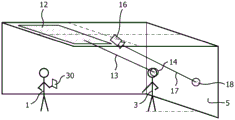
Referring to fig. 1, a user 1 and a mannequin 3 are illustrated in a retail environment. A user is utilizing the augmented reality display device 30 to configure the light output from the LED lighting fixture 12 and the redirectable point lighting fixture 16. One or more LED-based light sources of the LED lighting fixture 12 are configured to provide light output generally along line 13 to provide illumination of the face of the mannequin 3, as shown generally at circle 14. For example, one or more selected directional LEDs of the LED lighting fixture 12 may be illuminated to a desired level to provide the illustrated directional light output. The redirectable spot lighting fixture 16 is also configured to provide a light output generally along line 17 to provide lighting on the wall 5 of the retail environment, as shown generally at circle 18. For example, the pan, tilt, beam width, and/or intensity of the redirectable spot lighting fixture 16 may be adjusted (e.g., via a motor) to provide illumination as shown generally at circle 18. The redirectable spot lighting fixtures 16 may provide general lighting of the wall 5, or may alternatively be directed at a particular display on the wall 5 for illumination of such display.
In some embodiments, the augmented reality display device 30 may be a portable electronic device having a display 31 on one side and a camera on the side opposite the display. In some embodiments, the display may provide images of the environment captured by a camera of display device 30, and the images may be overlaid with one or more overlays (such as those described herein). For example, an image captured by a camera of display device 30 may be overlaid with one or more representations of lighting effects, light output directions, and/or lighting sources. In alternative embodiments, the display device 30 may overlay images captured by a remote camera and/or images that do not necessarily correspond to the location where the display device 30 is currently located (e.g., a user may modify the lighting parameters from a remote location). In some embodiments, the display may provide a 3D rendering, a schematic representation, or other representation of the environment, and may include one or more representations of lighting effects, light output directions, and/or lighting sources. Display device 30 is provided herein as an example of a display and user interface that may be used to implement one or more of the systems and/or methods described herein. However, persons of ordinary skill in the art having benefit of the present disclosure will recognize and appreciate that in alternative embodiments, additional and/or alternative displays and user interfaces may be utilized that provide a representation of the actual lighting environment, enable manipulation of lighting parameters of the lighting system within the lighting environment, and optionally provide an indication of capabilities and constraints of the lighting system.
As described herein, the user 1 may utilize the display device 30 to provide a desired lighting effect for a selected location (e.g., via direct input to a user interface of the display device 30). Based on the provided input, the display device may in some embodiments immediately generate and provide control signals to the lighting fixtures 12 and/or 16 (e.g., via a network utilizing one or more communication protocols such as DMX, ethernet, bluetooth, ZigBee, and/or Z-Wave) so that the user 1 can immediately see the real world effects of the selected control parameters. In another embodiment, the illumination system is not immediately controlled, but may be adjusted later (directly via the display device 30 or by a separate controller) based on the selected control parameters.
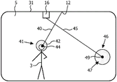
Referring to fig. 2, a display 31 of the augmented reality display device 30 of fig. 1 is illustrated. Provided on the display 31 are a representation of the mannequin 3, a representation of the wall 5, a representation of the redirectable point lighting fixture 16, and a representation of the LED lighting fixture 12. Shown extending from the LED lighting fixture 12 is a bar 40. The bar 40 is interposed between the LED lighting fixture 12 and the lighting representation 41 above the head of the manikin 3. The bar 40 provides an indication of the direction of light output provided by the LED lighting fixture 12, and the lighting representation 41 affixed to the bar 40 provides an indication of the area illuminated by the light output provided by the LED lighting fixture 12.
The illustrated illuminated representation 41 has an outer circle 42 and an inner circle 44. The inner circle 44 may indicate one or more characteristics of the light source of the LED lighting fixture 12. For example, the size of inner circle 44 may indicate the beam width of the light output of the LEDs of the LED lighting fixture that are active and directed at the mannequin. Also, for example, shading of the inner circle 44 may indicate a dimming value of such an LED. For example, the grey levels between black and white may be mapped to dimming levels of the lamp. Thus, by looking at the shadow of inner circle 44, the user will be able to confirm whether the dimming level can be increased and/or decreased to alter the illumination at the effect location. The outer circle 42 indicates one or more characteristics of the lighting effect provided by the output from the LED lighting fixture 12 at the lighting effect location (e.g., the face of the mannequin 3 in fig. 2). For example, the size of the outer circle 42 may indicate the size of the lighting effect provided by the output from the LED lighting fixture 12 at the lighting effect location. Also, for example, the shading of the outer circle 42 may indicate the illumination provided by the output from the LED lighting fixture 12 to the illumination object at the lighting effect location. The indication of the illumination provided to the illumination object by the output from the LED lighting fixture 12 may be determined based on, for example, characteristics of LEDs of the LED lighting fixture 12 illuminating the lighting effect location, dimming levels of the LEDs, and/or distances between the LEDs and the illumination object.
Illustrated as extending from the spot lighting fixture 16 is a bar 45. The bar 45 is interposed between the spot lighting fixture 16 and the lighting representation 46 on the wall 5. The bar 45 provides an indication of the direction of light output provided by the spot lighting fixture 16, and the lighting representation 46 affixed to the bar 45 provides an indication of the area illuminated by the light output provided by the spot lighting fixture 16.
The illuminated representation 46 has an outer circle 47 and an inner circle 49. The inner circle 49 indicates one or more characteristics of the light source of the spot lighting fixture 16. For example, the size of inner circle 49 may indicate the beam width, and the shading of inner circle 49 may indicate the dimming value. Outer circle 47 indicates one or more characteristics of the lighting effect provided by the output from point light fixture 16 at the lighting effect location. For example, the size of the outer circle 47 may indicate the size of the lighting effect, and the shading of the outer circle 47 may indicate the illumination provided to the illumination object at the location of the lighting effect.
Although outer circles 42, 47 and concentric inner circles 44, 49 are illustrated in fig. 2, in alternative embodiments, the outer circles 42, 47 and/or the inner circles 44, 49 may alternatively be another shape. For example, in some embodiments, the outer circle 42 and/or the inner circle 44 may be triangular, rectangular, oval, or polygonal. Also, in some embodiments, outer circles 42, 47 and inner circles 44, 49 may not be concentric with each other. Also, in some embodiments, the inner circles 44, 49 may not be provided to be enclosed within the outer circles 42, 47. For example, all or a portion of inner circle 44 may be provided outside of outer circle 42. Also, for example, in some embodiments, outer circles 42, 47 and/or inner circles 44, 49 may be shaped to provide an indication of the beam shape and/or lighting effect of the light source. For example, a first beam shape may be represented by a first shape and a second beam shape may be represented by a second shape. Alternatively, the beam shape and the shape representing the beam shape may correspond.
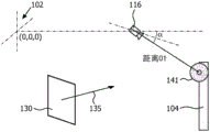
Fig. 3 illustrates the positioning of the augmented reality display device 130, the re-orientatable point lighting fixture 116 and the object 104 within the coordinate system of the real environment having the reference point at 102. An illumination representation 141 is also illustrated. The coordinate system is illustrated as an example of one of many coordinate systems that may be utilized. In some embodiments, the coordinate system may include GPS coordinates and/or local coordinates. The redirectable point lighting fixture 116 is located at a position spaced along a single axis relative to a reference point at 102. The position of the redirectable spot lighting fixture 116 within the coordinate system may be provided via configuration by the user (e.g., through user entry of coordinates) or with one or more position methods. The direction of the light beam produced by the spot lighting fixture 116 may also be determined using pan and/or tilt values communicated to the fixture 116, for example, by a controller directing the fixture 116 and/or via feedback from a motor of the fixture 116. For example, the controller may control the light fixture 116 using a DMX control protocol, and the pan and tilt values may be derived from DMX control signals sent to the light fixture 116. The distance between the light fixture 116 and the lighting representation 141 is also determinable. For example, the distance may be determined via a distance sensor (e.g., a laser) provided on the light fixture 116 and aimed in the same direction as the center of the beam produced by the light fixture 116. Also, for example, if a virtual model of the real environment is available and includes the locations of the lighting fixtures 116 and the object 104, then the distance may be calculated.
The position and/or viewing angle(s) (generally indicated by arrow 135) of display device 130 are also determinable. For example, the location of display device 130 within the coordinate system may be provided via configuration by the user (e.g., by the user typing in coordinates) or with one or more location methods. Also, for example, the perspective(s) of the display device may be determined via orientation sensors, such as digital compasses (e.g., magnetometers, gyrocompasses, and/or hall effect sensors), gyroscopes, accelerometers, and/or three-axis electronic compasses, among others. The sensor(s) of display device 130 may include a GPS sensor or other sensor capable of determining the location of display device 130 within the environment; an electronic compass or other sensor capable of determining the direction in which the camera of the display device 130 is directed; and a variable focus controller or other sensor of the camera that can detect the angle of view of the camera.
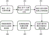
These positions, distances and/or angles may be used to detect and define the position of the spot on the display device 130 or other control device with the illumination representation presented on the display. For example, in some embodiments, a virtual reality display of the actual environment may be created using, for example, a schematic representation of the actual environment and/or a 3D model of the environment. In other embodiments, an augmented reality display may be created. FIG. 4 illustrates one embodiment of a method of situating a lighting effect in an augmented reality display. At step 201 and 203, the position of the lighting effect in the real environment is determined. At step 201, the position of one or more light sources is determined. At step 202, the direction of the light beam(s) produced by each light source is determined. At step 203, the distance between the light source(s) and the lighting effect is determined. Step 201-203 may utilize one or more sensors and/or values such as those discussed herein with respect to fig. 3.
At step 204, registration occurs to align the virtual object with the real object in the augmented reality display. For example, in some embodiments, tagging and video processing may be used to register virtual objects with real objects in an augmented reality display. Markers can be placed in a real environment and their positions configured. The markers are then detected in the enhanced video display using video processing. Also, for example, in some embodiments, a coarse 3D model of the real environment may be made, and with video processing, elements of the real environment (e.g., corners of a room) may be detected and mapped to the coarse 3D model. Also, for example, in some embodiments, geometric reasoning may be utilized. For example, the detected position of the display device 130 and the aiming parameters may be measured and mapped onto coordinates of the environment. The camera and/or display characteristics of the display device 130 may also be taken into account.
At step 205, two virtual shapes are created in the virtual space at the location of the lighting effect. The virtual shape may include inner and outer concentric shapes. In some embodiments, the size, shading, color, and/or shape of the inner virtual shape may be designed to represent characteristics of the light source, and the size, shading, color, and/or shape of the outer virtual shape may be designed to represent characteristics of the lighting effect. For example, the diameter of the inner shape may be an indication of the beam width, and the grey scale of the inner shape may be an indication of the dimming level of the light source. Also, for example, the diameter of the outer shape may be an indication of the size of the effect, and the grayscale of the outer shape may represent the illumination of the illumination target. These virtual shapes are mapped in the display of the augmented reality device along with the real pictures.
In step 206, a virtual bar is drawn connecting the virtual shape with the light source. As described herein, in various embodiments, the virtual bar may be made movable. For example, when moving the virtual shape, the effect end of the bar may be configured to move with the virtual shape, and the light source end of the bar remains in place. When moving the strip, the effect end of the strip may be configured to remain at the same position while the lamp end of the strip moves (e.g., to another light source). Although solid lines are illustrated in the figures, it is to be understood that other fiducial markers may be utilized instead of and/or in addition to solid lines. For example, in some embodiments, dashed lines, irregularly shaped solid and/or dashed lines, and/or dashed or solid lines made up of multiple symbols may be provided. Moreover, although the solid lines are shown as extending completely between and connecting the virtual lighting representation and the virtual light sources, in some embodiments the bars (or other indicia) may extend only partially between the virtual lighting representation and the virtual light sources. Also, for example, in some embodiments, a bar (or other indicia) may be associated with the illumination representation only (indicating the direction of artificial light thereon), without necessarily representing the light source on the virtual display.
In controlling and/or configuring lighting in a real environment, a user need not be present in the real environment. The specific moment in time at which the image or model of the real environment is obtained may be a moment in time that is not related to the moment in time at which the user indicates the desired lighting effect in the lighting system and optionally receives an indication of the capabilities and constraints of the lighting system. For example, the image of the real environment may be stored in a database together with information of the lighting system and information of the environment. Or, in another example, the device may include a camera for obtaining images of the real environment, and after obtaining the images, the device may be migrated to another room, and/or the user may move the device to a more comfortable position before providing the user input. The depiction of the real environment may be a schematic view of the environment or the depiction may be a recording of the environment, such as a photograph taken at a particular time.
In some embodiments, the real environment and/or lighting system model may be obtained via known techniques, such as so-called darkroom calibration or techniques utilizing coded light from the light sources and an image sensor detecting the light source footprint and detecting the identification code of the light source. In other embodiments, the real environment and/or the lighting system model may be authored by a person, for example, a technician installing the lighting system in the environment.
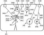
FIG. 5 illustrates a display 331 that illustrates the mannequin 303 in a first orientation and the light sources 316A-E and 312 in a first configuration. In some embodiments, the display 331 may be part of a portable device, such as a mobile smart phone or tablet computer. Optionally, the portable device may include a responsive touch screen and be responsive to one or more touch screen methods, and/or the portable device may include an orientation sensor and be responsive to one or more movements of the portable device. Display 331 may, in some embodiments, present an augmented reality representation of the real environment, and may, in some embodiments, present a full virtual representation of the real environment.
The display 331 represents the mannequin 303 and five separate re-orientable light sources 316A-E and 312. The re-directable light sources 316A-E may be, for example, light sources of a motorized spot lighting fixture. The light source 312 may be, for example, an LED-based lighting fixture that includes a re-directable light output via manipulation of one or more LEDs and/or optical components thereof. In some embodiments, one or more non-re-orientatable light sources may be provided. Optionally, such a non-re-orientatable light source may comprise at least one adjustable parameter (e.g. intensity, beam width, colour). Each of the re-directable light sources 316A-E, 312 is associated with a strip 340A-E, 345 extending therefrom and an illuminated representation 341A-E, 346 at opposite ends of the strip 340A-E, 345. Each illumination representation 341A-E, 346 includes an outer circle 342A-E, 347 and an inner circle 344A-E, 349.
The size of each inner circle 344A-E, 349 is indicative of the beam width of the respective light source 316A-E, 312. The shading of each inner circle 344A-E, 349 indicates the dimming level of the respective light source 316A-E, 312. The size of each outer circle 342A-E, 347 indicates the size of the effect produced at the aiming location of the respective light source 316A-E, 312. The shading of each outer circle 344A-E, 349 indicates the illumination level at the aiming location of the respective light source 316A-E, 312. In FIG. 5, illumination representations 341A and 341C are illustrated as being superimposed atop mannequin 303. The bars 340A and 340C indicate that the lighting representations 341A and 341C were produced by the respective lighting fixtures 316A and 316C, and the light output that produced the lighting representations 341A and 341C came from the direction generally indicated by the respective bars 340A and 340C. The illumination representations 341B, D, E, 346 are illustrated on a wall positioned behind the manikin 303.
In fig. 6, the mannequin 303 is moved to the second position. It is noted that the illumination representations 341A and 341C are now directed to the wall behind the mannequin 303 because the mannequin 303 has moved. Thus, the outer circles 342A and 342C are larger because the distance between the light sources 316A and 316C and the wall is larger than the distance between the light sources 316A and 316C and the mannequin 303 in its orientation of FIG. 5. Also, because the same amount of light from light sources 316A and 316C is spread out over a larger area (due to the increased distance), outer circles 342A and 342C are illustrated as darker in fig. 6 to indicate a reduced intensity of the lighting effect. Since the inner circles 344A and 344C represent the characteristics of the light sources, they remain the same because the characteristics of the light sources (e.g., beam width or dimming level) do not change.
In fig. 6, light sources 312 and 316E are also illustrated as being off. The user may turn off the light source by using one or more inputs. For example, in the case of a touch screen device, the user may double click on a light source to turn it on or off.
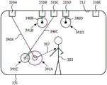
In fig. 7, the mannequin 303 is still in the second orientation. The illumination representation 341A is illustrated as being redirected to the mannequin 303 in fig. 7. In some embodiments, the illumination representation 341A may be redirected in the direction of arrow 307 (fig. 6) via clicking and dragging the illumination representation 341A with the pointer 308 using, for example, a mouse or trackball device. In other embodiments, the illumination representation 341A may be redirected via one or more known touch screen methods. For example, the illumination representation 341A may be selected and dragged with a finger. Also, for example, the illuminated representation 341A may be selected with a finger, and then the orientation of the display 331 may be adjusted by the user to adjust the illuminated representation 341A. For example, tilting the display 331 will move the illuminated representation 341A in a vertical direction. Feed-forward may optionally be provided on the maximum adjustability of the illumination representation 341A (e.g., defined by the maximum rotation angle of the point illumination light source 312A and/or obstacles in the real environment). For example, when the illumination representation 341A is selected, the inaccessible area(s) may be grayed out, thereby indicating to the user the range of movement of the illumination representation 341A. Also, for example, when the illumination representation 341A is selected, the accessible region(s) may additionally or alternatively be highlighted, thereby indicating to the user the range of movement of the illumination representation 341A.
During the redirection action of the user, the pan and tilt values of the illumination source 316A change in the direction of the new effect location, and based on the coordinates of the source and the distance between the light source and the light effect, the position of the illumination representation is determined and mapped to the virtual screen. This results in a new positioning of the illumination representation 341A and gives the user the possibility to place the illumination representation 341A on the new positioning of the manikin 303. The bar 340A is also adapted to the new positioning of the illuminated representation 341A on the screen.
In some embodiments, the pan and tilt values of illumination source 316A may be derived from movement of a user's finger on a touch screen or from movement of a pointer on a screen via another input device. For example, an initial movement of the illumination representation 341A to the mannequin 303 by the user on the virtual screen will cause the controller to direct the illumination source 316A to initially pan and/or tilt in a direction generally toward the mannequin 303 in the real environment. After the initial pan and/or tilt, the new location of the lighting effect in the real environment may be determined using, for example, a distance sensor of the lighting source 316A and/or other inputs discussed herein. The new location of the illuminated representation 341A may then be updated and located on the display 331. The new location may be different from the intended target (e.g., location of a finger on the touch screen) and, if so, the controller may direct the illumination source 316A to further pan and/or tilt and then determine the location of the illumination effect in the real environment and update the location on the display 331. After one or more iterations of adjusting the light source 316A, determining the real-world location of the lighting effect, updating the location on the display 331, and further adjusting the light source if the location is different from the intended target, the real-world and virtual locations of the lighting effect will match the intended target.
One potential sequence of events when the user adjusts the lighting representation 341A to the mannequin 303 on the virtual screen involves the user tapping the lighting representation 341A and then dragging his finger in the direction of arrow 307. In response, the illumination source 316A is adjusted in the direction of arrow 307, but the real world lighting effect is initially located on a wall that is located behind the mannequin 303. The user may continue to drag his finger further in the direction of arrow 307 and the real world lighting effect will continue on the wall behind the mannequin 303 until it intersects the mannequin 303. At this point, the illuminated representation 341A is positioned correctly and its position will be updated in the display 331 to reflect that it is on top of the mannequin 303. The location and size of the effect may be determined based on the determined distance between the illumination source 316A and the mannequin 303, and the virtual display characteristics (shading, size) of the effect aspect of the illumination representation 341A may be determined based in part on the distance.
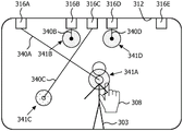
In fig. 8 and 9, the size of the lighting effect indicated by lighting representation 341C has been adjusted by the user to be smaller (as indicated by the smaller size of outer circle 342C). This may be done via user input. For example, the user may utilize a two-finger pinch gesture on top of the illumination representation 341C (optionally upon selection thereof) to shrink the size of the illumination effect. Also, for example, the user may double click on the lighting representation 341C and be presented with a list of adjustable parameters for lighting effects and/or light sources. The user's input may then be communicated to the lighting system to cause the desired narrowing of the lighting effect in the real environment. For example, the positioning of the reflector around light source 316C may be adjusted to narrow the light output. The size of inner circle 344C may also be reduced to identify a narrower beam width of light source 316C. The intensity of light source 316C is not adjusted by the user between fig. 7 and 8. As a result, the intensity of the lighting effect is greater in fig. 8, as indicated by the lighter shading of the outer circle 342C.
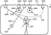
In fig. 9, bar 340C is shown as being adjusted to light source 316E, thereby changing to bar 340E. The bar 340C may be moved to the light source 316E by selecting the bar with the pointer 308 and moving the bar in the direction of arrow 309. The bar 340C may also be moved using a touch screen method (e.g., select and drag the bar 340C, select the bar 340C, and tilt the display 331). When bar 340C is moved to light source 316E, the lighting effect on mannequin 303 is now produced by light source 316E and comes from the direction indicated by bar 340E. Illumination representations 341E may be adjusted to correspond to the parameters of new light sources 316E if they do differ from light sources 316A (e.g., if light sources 316E are farther away or have higher light output). Several dashed lines are indicated in fig. 9. The dashed lines may indicate discrete light sources to which the bar 340C may be adjusted. In some lighting fixtures, the strips may be adjusted to multiple discrete positions maintained with a single light source. For example, in the case of a light source whose relative positioning is moving in a real environment (e.g. a light source placed on a lift), the strip may move in a continuous manner. Also, for example, where the lighting fixture has multiple directional LED sources, the strips may be tuned to multiple discrete LEDs within the lighting fixture.
In the illustrated embodiment, the effect end of the bar 340C remains at the same location while the light source end moves to a new position. If only a few possibilities of moving the light source end are available (e.g., a discrete number of light sources), the bar 340C may jump to the nearest possible light source while moving until it is released at the desired light source. In the case of light on the elevator, the bar can move smoothly while the elevator follows the movement of the light source end of the bar. In some alternative embodiments, when the bar is moved close to the light source representation on the display 331, the light source becomes active (the representation changes appearance and/or the real world light source may show a preview of the effect instantaneously) and when the user releases the bar 340C, it automatically connects to the nearest light source. Optionally, areas not accessible by the bar 340C (e.g., light sources that are too far away and/or blocked by obstacles) may be grayed out, thereby indicating to the user the available range, and/or areas accessible by the bar 340C may be highlighted.
Other characteristics of the light effects may optionally be changed using known touch screens, gesture interaction methods, and/or other inputs (e.g., keyboard, stylus, and/or mouse). For example, one or more of color temperature, color, beam shape, and filters or shutters that may be placed in front of the light source may be altered. For example, the beam shape may be altered by double-clicking on the illumination representation and selecting from a plurality of predetermined beam shape options. Optionally, when the beam shape is altered, the shape of the illumination representation may be altered to correspond to such beam shape. Also, optionally, when changing color or color temperature, the color of the lighting representation may be changed to correspond to such selected color.
Also, the sequence of changing the temporal or spatial behavior of the light effect may be activated via a user input. The light source parameters may also optionally be locked via user input to prevent changes, such as locking the pan, tilt and/or dimming level of the light source. When a parameter is locked, the system can prevent interaction on the screen against such a parameter. For example, when moving the bar, the bar may not jump to a light source having a locked pan parameter that does not correspond to the pan parameter required to create the lighting effect at the desired location.
Also, constraints may be placed on certain lighting effects. For example, a constraint of "keep intensity at about 1000 lux" may be placed on the lighting effect. When the lighting effect is redirected, the distance to the light source and thus the intensity may change. This change may optionally be automatically compensated for by adjusting the dimming level of the light source.
When multiple illumination representations are directed to the same location, the illumination representations (circles in the figure) may be stacked on top of each other in the display. In some embodiments, a user may navigate through the various lighting representations in the stack by making several taps on the lighting representations of the stack.
In some embodiments, the lighting representation may be fixable on an object in the real environment such that the lighting representation will follow the object as the object moves in the real environment. For example, one or more actors may be tracked across stages. Also, for example, the product on the shelf may be illuminated even when it is now picked up and then put back to a slightly different location. The interface may provide an interactive mechanism for the user to indicate which objects should be illuminated and with which lighting characteristics. Characteristics such as illumination intensity and spot size may be fixed for a certain object.
While several inventive embodiments have been described and illustrated herein, those of ordinary skill in the art will readily envision a variety of other means and/or structures for performing the functions and/or obtaining the results and/or advantages described herein, and each of such variations and/or modifications is deemed to be within the scope of the inventive embodiments described herein. More generally, those skilled in the art will readily appreciate that all parameters, dimensions, materials, and configurations described herein are meant to be exemplary and that the actual parameters, dimensions, materials, and/or configurations will depend upon the specific application or applications for which the teachings of the present invention is/are used. Those skilled in the art will recognize, or be able to ascertain using no more than routine experimentation, many equivalents to the specific embodiments of the invention described herein. It is, therefore, to be understood that the foregoing embodiments are presented by way of example only and that, within the scope of the appended claims and equivalents thereto, inventive embodiments may be practiced otherwise than as specifically described and claimed. Inventive embodiments of the present disclosure are directed to each individual feature, system, article, material, kit, and/or method described herein. In addition, any combination of two or more such features, systems, articles, materials, kits, and/or methods, if such features, systems, articles, materials, kits, and/or methods are not mutually inconsistent, is included within the scope of the present disclosure.
All definitions, as defined and used herein, should be understood to control dictionary definitions, definitions in documents incorporated by reference, and/or ordinary meanings of the defined terms.
The indefinite articles "a" and "an", as used herein in the specification and in the claims, should be understood to mean "at least one" unless clearly indicated to the contrary.
The phrase "and/or" as used herein in the specification and claims should be understood to mean "either or both" of the elements so connected, i.e., the elements being connected in some instances and separately present in other instances. Multiple elements listed with "and/or" should be interpreted in the same manner, i.e., "one or more" of the elements so connected. In addition to the elements specifically identified by the "and/or" clause, other elements may optionally be present, whether related or unrelated to those elements specifically identified. Thus, as a non-limiting example, a reference to "a and/or B," when used in conjunction with an extensible language such as "comprising," may refer in one embodiment to a alone (optionally including elements other than B); in another embodiment, only B (optionally including elements other than a); in yet another embodiment, refer to both a and B (optionally including other elements); and so on.
As used herein in the specification and claims, the phrase "at least one" in reference to a list of one or more elements should be understood to mean at least one element selected from any one or more of the elements in the list of elements, but not necessarily including at least one of each element specifically listed within the list of elements, and not excluding any combination of elements in the list of elements. This definition also allows that elements may optionally be present other than the elements specifically identified within the list of elements to which the phrase "at least one" refers, whether related or unrelated to those elements specifically identified. It will also be understood that, in any method claimed herein that includes more than one step or action, the order of the steps or actions of the method is not necessarily limited to the order in which the steps or actions of the method are recited, unless clearly indicated to the contrary.
Also, reference numerals appearing in the claims in parentheses (if any) are provided merely for convenience and should not be construed as limiting the claims in any way.
Claims (6)
1. An interactive system for controlling re-directable lighting in a lighting environment, comprising:
an interactive display (31, 331) having a representation of the lighting environment, the representation comprising a plurality of light sources (41, 46, 141, 341A-E, 346), at least one repositionable lighting representation (41, 46, 141, 341A-E, 346), and a repositionable orientation reference mark (40, 45, 340A-E, 345), the repositionable orientation reference mark (40, 45, 340A-E, 345) being associated with the repositionable lighting representation (41, 46, 141, 341A-E, 346) and indicating a direction of light for the lighting representation (41, 46, 141, 341A-E, 346),
wherein the repositionable lighting representation includes an outer shape and an inner shape enclosed within the outer shape, and wherein a size, shading, color, or shape of one of the outer shape or the inner shape is designed to represent a characteristic of the light source, and wherein a size, shading, color, or shape of the other of the outer shape or the inner shape is designed to represent a characteristic of the lighting effect.
2. The interactive system of claim 1, wherein said fiducial marker (40, 45, 340A-E, 345) extends from an adjacent one of said plurality of light sources (41, 46, 141, 341A-E, 346) toward said repositionable lighting representation (41, 46, 141, 341A-E, 346) and is individually repositionable to other ones of said light sources (41, 46, 141, 341A-E, 346).
3. The interactive system of claim 2, wherein said fiducial marker (40, 45, 340A-E, 345) is a line.
4. The interactive system of claim 1, wherein said repositionable lighting representation (41, 46, 141, 341A-E, 346) corresponds to a current position of said repositionable lighting representation and a light source of said light sources to which said fiducial marker extends.
5. The interactive system of claim 1, wherein the repositionable lighting representations (41, 46, 141, 341A-E, 346) include a light source representation and a lighting effect representation.
6. The interactive system of claim 5, wherein said light source representation comprises at least one of a variable size and a variable shading corresponding to a lighting parameter of one of said light sources.
Applications Claiming Priority (3)
| Application Number | Priority Date | Filing Date | Title |
|---|---|---|---|
| US201161570319P | 2011-12-14 | 2011-12-14 | |
| US61/570319 | 2011-12-14 | ||
| CN201280061623.9A CN103999551B (en) | 2011-12-14 | 2012-12-14 | Method and apparatus for controlling illumination |
Related Parent Applications (1)
| Application Number | Title | Priority Date | Filing Date |
|---|---|---|---|
| CN201280061623.9A Division CN103999551B (en) | 2011-12-14 | 2012-12-14 | Method and apparatus for controlling illumination |
Publications (2)
| Publication Number | Publication Date |
|---|---|
| CN109041372A CN109041372A (en) | 2018-12-18 |
| CN109041372B true CN109041372B (en) | 2021-01-05 |
Family
ID=47631487
Family Applications (2)
| Application Number | Title | Priority Date | Filing Date |
|---|---|---|---|
| CN201810744351.1A Active CN109041372B (en) | 2011-12-14 | 2012-12-14 | Method and apparatus for controlling lighting |
| CN201280061623.9A Active CN103999551B (en) | 2011-12-14 | 2012-12-14 | Method and apparatus for controlling illumination |
Family Applications After (1)
| Application Number | Title | Priority Date | Filing Date |
|---|---|---|---|
| CN201280061623.9A Active CN103999551B (en) | 2011-12-14 | 2012-12-14 | Method and apparatus for controlling illumination |
Country Status (6)
| Country | Link |
|---|---|
| US (3) | US10465882B2 (en) |
| EP (1) | EP2749144A2 (en) |
| JP (1) | JP6165164B2 (en) |
| CN (2) | CN109041372B (en) |
| RU (1) | RU2666770C2 (en) |
| WO (1) | WO2013088394A2 (en) |
Families Citing this family (49)
| Publication number | Priority date | Publication date | Assignee | Title |
|---|---|---|---|---|
| RU2557084C2 (en) * | 2010-01-29 | 2015-07-20 | Конинклейке Филипс Электроникс Н.В. | System and method for interactive illumination control |
| US20140028853A1 (en) * | 2012-07-24 | 2014-01-30 | SIRCHIE Acquisition Company LLC | Dual camera digital video comparator for forensic evidence |
| US20150355829A1 (en) * | 2013-01-11 | 2015-12-10 | Koninklijke Philips N.V. | Enabling a user to control coded light sources |
| US9562676B2 (en) * | 2013-09-27 | 2017-02-07 | Osram Sylvania Inc. | Control techniques for lighting fixtures having spatial distribution control capabilities |
| EP2911040A1 (en) * | 2014-02-25 | 2015-08-26 | Thomson Licensing | Method and device for controlling a scene comprising real and virtual objects |
| EP2922371B1 (en) * | 2014-03-21 | 2020-10-28 | Osram Sylvania Inc. | Techniques and photographical user interface for controlling solid-state luminaire with electronically adjustable light beam distribution |
| US9884586B2 (en) | 2014-03-28 | 2018-02-06 | Pioneer Corporation | Vehicle lighting device |
| EP3180963B8 (en) | 2014-08-11 | 2019-04-10 | Signify Holding B.V. | Light system interface and method |
| US10762463B2 (en) * | 2014-08-28 | 2020-09-01 | Nicolas Bissantz | Electronic boss |
| CN106664783B (en) * | 2014-09-01 | 2019-10-18 | 飞利浦灯具控股公司 | Lighting system control method, computer program product, wearable computing devices and lighting system external member |
| CN104244530A (en) * | 2014-09-25 | 2014-12-24 | 苏州乐聚一堂电子科技有限公司 | Vibration-sensing color-changing lighting effect system |
| US10345768B2 (en) * | 2014-09-29 | 2019-07-09 | Microsoft Technology Licensing, Llc | Environmental control via wearable computing system |
| US9872356B1 (en) | 2015-02-03 | 2018-01-16 | Google Llc | Interactive lighting handshake |
| CN106162117B (en) * | 2015-04-10 | 2019-04-16 | 北京智谷睿拓技术服务有限公司 | Display control method and device |
| CN106293557B (en) * | 2015-05-04 | 2019-12-03 | 北京智谷睿拓技术服务有限公司 | Display control method and device |
| JP6215881B2 (en) | 2015-08-05 | 2017-10-18 | ミネベアミツミ株式会社 | Variable equipment system |
| CN105142276B (en) * | 2015-08-24 | 2018-02-23 | 浙江大丰实业股份有限公司 | A kind of stage light effect real-time control system |
| CN105142275B (en) * | 2015-08-24 | 2018-02-23 | 浙江大丰实业股份有限公司 | A kind of light efficiency control device |
| CN105142274B (en) * | 2015-08-24 | 2018-02-23 | 浙江大丰实业股份有限公司 | A kind of light efficiency control device based on Real-time Feedback |
| WO2017067764A1 (en) * | 2015-10-19 | 2017-04-27 | Philips Lighting Holding B.V. | Harmonized light effect control across lighting system installations |
| CN111601420B (en) * | 2015-11-03 | 2022-11-01 | 雷蛇(亚太)私人有限公司 | Control method, computer readable medium, and controller |
| CN105554987A (en) * | 2016-01-30 | 2016-05-04 | 广州彩熠灯光有限公司 | Control system and control method for 3D visualization and gesture adjustment stage lamp |
| JP2019522251A (en) * | 2016-04-21 | 2019-08-08 | シグニファイ ホールディング ビー ヴィ | A computing cloud to monitor the physical environment |
| WO2017186532A1 (en) * | 2016-04-26 | 2017-11-02 | Philips Lighting Holding B.V. | Method and system for controlling a lighting device. |
| US10477659B1 (en) | 2016-09-15 | 2019-11-12 | Apple Inc. | Adjustable lighting systems |
| WO2018077640A1 (en) * | 2016-10-27 | 2018-05-03 | Philips Lighting Holding B.V. | A method of storing object identifiers |
| JP2018098155A (en) * | 2016-12-09 | 2018-06-21 | 岩崎電気株式会社 | Lighting control system and program |
| JP6848420B2 (en) * | 2016-12-09 | 2021-03-24 | 岩崎電気株式会社 | Lighting control system and program |
| CN110115112B (en) * | 2017-01-04 | 2021-08-13 | 昕诺飞控股有限公司 | Lighting control |
| CN110268806B (en) * | 2017-02-16 | 2022-01-04 | 昕诺飞控股有限公司 | Controller for indicating presence of virtual object via lighting device and method thereof |
| AT519679A1 (en) * | 2017-02-27 | 2018-09-15 | Zactrack Gmbh | Method for calibrating a rotating and pivoting stage equipment |
| EP3393213B1 (en) * | 2017-04-03 | 2022-10-12 | ROBE lighting s.r.o. | Follow spot control system |
| US10678220B2 (en) * | 2017-04-03 | 2020-06-09 | Robe Lighting S.R.O. | Follow spot control system |
| ES2945138T3 (en) | 2017-06-01 | 2023-06-28 | Signify Holding Bv | Virtual character representation system and method thereof |
| US11094091B2 (en) * | 2017-06-01 | 2021-08-17 | Signify Holding B.V. | System for rendering virtual objects and a method thereof |
| WO2018224390A1 (en) * | 2017-06-08 | 2018-12-13 | Philips Lighting Holding B.V. | Mapping a light effect to light sources using a mapping function |
| US10922878B2 (en) * | 2017-10-04 | 2021-02-16 | Google Llc | Lighting for inserted content |
| US20210068233A1 (en) * | 2018-01-16 | 2021-03-04 | Sony Corporation | Illumination control device, illumination control method, illumination device, and illumination system |
| US11845002B2 (en) * | 2018-02-02 | 2023-12-19 | Lü Aire De Jeu Interactive Inc. | Interactive game system and method of operation for same |
| EP3592119A1 (en) * | 2018-06-08 | 2020-01-08 | ROBE lighting s.r.o. | Follow spot control system |
| WO2020088990A1 (en) * | 2018-10-30 | 2020-05-07 | Signify Holding B.V. | Management of light effects in a space |
| DE102019133754A1 (en) * | 2018-12-10 | 2020-06-10 | Electronic Theatre Controls, Inc. | SYSTEMS AND METHODS FOR ADJUSTING A LIGHTING BODY IN AN EVENT AREA |
| DE102019133753A1 (en) * | 2018-12-10 | 2020-07-16 | Electronic Theatre Controls, Inc. | TOOLS FOR AUGMENTED REALITY IN LIGHT DESIGN |
| CN111885794B (en) * | 2020-08-27 | 2023-01-31 | 北京七维视觉传媒科技有限公司 | Light control system and light control method |
| JP7237901B2 (en) * | 2020-09-14 | 2023-03-13 | ミネベアミツミ株式会社 | Sterilization system, sterilization device, control device, control method and control program |
| US11615586B2 (en) * | 2020-11-06 | 2023-03-28 | Adobe Inc. | Modifying light sources within three-dimensional environments by utilizing control models based on three-dimensional interaction primitives |
| US11423607B2 (en) | 2020-11-20 | 2022-08-23 | Adobe Inc. | Generating enriched light sources utilizing surface-centric representations |
| US11551409B2 (en) | 2020-12-01 | 2023-01-10 | Institut Mines Telecom | Rendering portions of a three-dimensional environment with different sampling rates utilizing a user-defined focus frame |
| CN114364099B (en) * | 2022-01-13 | 2023-07-18 | 达闼机器人股份有限公司 | Method for adjusting intelligent light equipment, robot and electronic equipment |
Citations (3)
| Publication number | Priority date | Publication date | Assignee | Title |
|---|---|---|---|---|
| CN1977209A (en) * | 2004-06-30 | 2007-06-06 | 皇家飞利浦电子股份有限公司 | Active system for ambient lighting using a video display as a signal source |
| CN101849436A (en) * | 2007-11-06 | 2010-09-29 | 皇家飞利浦电子股份有限公司 | Light management system with automatic identification of light effects available for a home entertainment system |
| CN101926226A (en) * | 2008-01-24 | 2010-12-22 | 皇家飞利浦电子股份有限公司 | Be used for the communication based on light of the configuration of light-sensing peripherals |
Family Cites Families (72)
| Publication number | Priority date | Publication date | Assignee | Title |
|---|---|---|---|---|
| US5307295A (en) * | 1991-01-14 | 1994-04-26 | Vari-Lite, Inc. | Creating and controlling lighting designs |
| US7251637B1 (en) * | 1993-09-20 | 2007-07-31 | Fair Isaac Corporation | Context vector generation and retrieval |
| US6421165B2 (en) | 1996-02-07 | 2002-07-16 | Light & Sound Design Ltd. | Programmable light beam shape altering device using programmable micromirrors |
| US7242152B2 (en) | 1997-08-26 | 2007-07-10 | Color Kinetics Incorporated | Systems and methods of controlling light systems |
| US6448987B1 (en) | 1998-04-03 | 2002-09-10 | Intertainer, Inc. | Graphic user interface for a digital content delivery system using circular menus |
| US6611297B1 (en) | 1998-04-13 | 2003-08-26 | Matsushita Electric Industrial Co., Ltd. | Illumination control method and illumination device |
| JP3477675B2 (en) * | 1999-06-04 | 2003-12-10 | インターナショナル・ビジネス・マシーンズ・コーポレーション | Pointer operation assist method |
| US20080140231A1 (en) * | 1999-07-14 | 2008-06-12 | Philips Solid-State Lighting Solutions, Inc. | Methods and apparatus for authoring and playing back lighting sequences |
| US20010030668A1 (en) * | 2000-01-10 | 2001-10-18 | Gamze Erten | Method and system for interacting with a display |
| US7202613B2 (en) * | 2001-05-30 | 2007-04-10 | Color Kinetics Incorporated | Controlled lighting methods and apparatus |
| US7031875B2 (en) * | 2001-01-24 | 2006-04-18 | Geo Vector Corporation | Pointing systems for addressing objects |
| US6883145B2 (en) | 2001-02-15 | 2005-04-19 | Denny Jaeger | Arrow logic system for creating and operating control systems |
| JP2003296757A (en) * | 2002-03-29 | 2003-10-17 | Canon Inc | Information processing method and device |
| DE602004026812D1 (en) * | 2003-03-26 | 2010-06-10 | Matsushita Electric Works Ltd | SIMULATION METHOD, PROGRAM AND DEVICE FOR PRODUCING A VIRTUAL THREE-DIMENSIONAL STAGE |
| DE602004005180T2 (en) * | 2003-05-07 | 2007-11-08 | Koninklijke Philips Electronics N.V. | USER INTERFACE FOR CONTROLLING LUMINAIRE DIODES |
| US6993404B2 (en) | 2003-07-11 | 2006-01-31 | Mks Instruments, Inc. | Graphical user interface with process quality indicator |
| ATE466309T1 (en) | 2003-11-20 | 2010-05-15 | Philips Solid State Lighting | LIGHTING SYSTEM MANAGER |
| JP4393169B2 (en) * | 2003-12-04 | 2010-01-06 | キヤノン株式会社 | Mixed reality presentation method and apparatus |
| JP4673570B2 (en) * | 2004-03-31 | 2011-04-20 | 株式会社セガ | Image generation apparatus, image display method, and program |
| US7355523B2 (en) * | 2004-04-15 | 2008-04-08 | Alberto Sid | Remote controlled intelligent lighting system |
| US20060085170A1 (en) * | 2004-08-11 | 2006-04-20 | Glaser Daniel C | Method and apparatus for modeling and analyzing light |
| CN100543515C (en) | 2004-09-24 | 2009-09-23 | 皇家飞利浦电子股份有限公司 | Illuminator |
| US8051148B2 (en) | 2005-01-13 | 2011-11-01 | National Instruments Corporation | Determining differences between configuration diagrams |
| CN100515149C (en) * | 2005-03-23 | 2009-07-15 | 皇家飞利浦电子股份有限公司 | Light condition recorder system and method |
| JP4738870B2 (en) * | 2005-04-08 | 2011-08-03 | キヤノン株式会社 | Information processing method, information processing apparatus, and remote mixed reality sharing apparatus |
| WO2006111927A1 (en) | 2005-04-22 | 2006-10-26 | Koninklijke Philips Electronics N.V. | Method and system for lighting control |
| JPWO2006134778A1 (en) * | 2005-06-14 | 2009-01-08 | 国立大学法人 電気通信大学 | Position detection apparatus, position detection method, position detection program, and mixed reality providing system |
| US7400458B2 (en) | 2005-08-12 | 2008-07-15 | Philips Lumileds Lighting Company, Llc | Imaging optics with wavelength dependent aperture stop |
| US20070070069A1 (en) * | 2005-09-26 | 2007-03-29 | Supun Samarasekera | System and method for enhanced situation awareness and visualization of environments |
| US8113679B2 (en) | 2005-12-12 | 2012-02-14 | Koninklijke Philips Electronics N.V. | Light system and method for creating a localized light |
| JP2009521087A (en) | 2005-12-22 | 2009-05-28 | コーニンクレッカ フィリップス エレクトロニクス エヌ ヴィ | Button device for colored lighting controller |
| CN101341799B (en) * | 2005-12-22 | 2012-01-11 | 皇家飞利浦电子股份有限公司 | User interface and method for control of light systems |
| CN101410667A (en) | 2006-03-23 | 2009-04-15 | 皇家飞利浦电子股份有限公司 | Lighting device with OLEDs |
| US8277316B2 (en) * | 2006-09-14 | 2012-10-02 | Nintendo Co., Ltd. | Method and apparatus for using a common pointing input to control 3D viewpoint and object targeting |
| WO2008038179A2 (en) | 2006-09-27 | 2008-04-03 | Koninklijke Philips Electronics N. V. | Color selection input device and method |
| WO2008059411A1 (en) * | 2006-11-17 | 2008-05-22 | Koninklijke Philips Electronics N.V. | Light wand for lighting control |
| US20080183337A1 (en) * | 2007-01-31 | 2008-07-31 | Fifth Light Technology Ltd. | Methods and systems for controlling addressable lighting units |
| CN101682959B (en) * | 2007-05-09 | 2014-03-05 | 皇家飞利浦电子股份有限公司 | Method and system for controlling lighting system |
| KR101649577B1 (en) * | 2007-05-22 | 2016-08-19 | 코닌클리케 필립스 엔.브이. | Remote lighting control |
| US8057069B2 (en) | 2007-07-03 | 2011-11-15 | Optimus Services Ag | Graphical user interface manipulable lighting |
| ATE531236T1 (en) * | 2007-12-31 | 2011-11-15 | Koninkl Philips Electronics Nv | METHOD AND APPARATUS FOR SUPPORTING THE DESIGN, SELECTION AND/OR CUSTOMIZATION OF LIGHTING EFFECTS OR LIGHTING SHOWS |
| US8373366B2 (en) * | 2008-01-16 | 2013-02-12 | Koninklijke Philips Electronics N.V. | User interface for scene setting control with light balance |
| CN101926228B (en) | 2008-01-24 | 2013-11-13 | 皇家飞利浦电子股份有限公司 | Color selection input device and method |
| RU2010138580A (en) | 2008-02-20 | 2012-03-27 | Конинклейке Филипс Электроникс Н.В. (Nl) | DEVICE FOR PRESENTATIONS OF THE OBJECT CONTAINING AN ELECTRONIC DISPLAY SYSTEM |
| DE102008017292A1 (en) * | 2008-04-04 | 2009-10-08 | Zumtobel Lighting Gmbh | Computer-aided system for managing and / or controlling a building management system |
| JP6072412B2 (en) | 2008-06-10 | 2017-02-01 | フィリップス ライティング ホールディング ビー ヴィ | User interface device for controlling the load of connected electrical consumer products, lighting system using such user interface device, method for controlling the use of electrical consumer product loads |
| FR2933827B1 (en) | 2008-07-11 | 2010-08-20 | Excem | MULTI-CHANNEL INTERFACE DEVICE WITH BALANCING CIRCUIT |
| US8494660B2 (en) | 2008-07-11 | 2013-07-23 | Koninklijke Philips N.V. | Method and computer implemented apparatus for controlling a lighting infrastructure |
| JP5319999B2 (en) * | 2008-09-25 | 2013-10-16 | パナソニック株式会社 | Lighting device |
| US8749497B2 (en) * | 2008-12-12 | 2014-06-10 | Apple Inc. | Multi-touch shape drawing |
| US20100208033A1 (en) * | 2009-02-13 | 2010-08-19 | Microsoft Corporation | Personal Media Landscapes in Mixed Reality |
| CN102461344B (en) * | 2009-06-03 | 2014-12-17 | 萨万特系统有限责任公司 | Method and device for controlling one or more device of physic room of structure |
| EP2438799B1 (en) * | 2009-06-05 | 2018-12-12 | Philips Lighting Holding B.V. | Lighting control device |
| WO2010143377A1 (en) * | 2009-06-08 | 2010-12-16 | パナソニック株式会社 | Fixation-object determination device and method |
| EP2446711B1 (en) * | 2009-06-25 | 2017-11-22 | Philips Lighting Holding B.V. | Effect-driven specification of dynamic lighting |
| US8159156B2 (en) | 2009-08-10 | 2012-04-17 | Redwood Systems, Inc. | Lighting systems and methods of auto-commissioning |
| CN101998013A (en) * | 2009-08-11 | 2011-03-30 | 株式会社东芝 | Device managing apparatus, device managing method, and icon display control method |
| JP4560128B1 (en) * | 2009-08-13 | 2010-10-13 | 株式会社パスコ | Map image integrated database generation system and map image integrated database generation program |
| RU2557084C2 (en) | 2010-01-29 | 2015-07-20 | Конинклейке Филипс Электроникс Н.В. | System and method for interactive illumination control |
| WO2011124271A1 (en) | 2010-04-09 | 2011-10-13 | Tomtom International B.V. | Method of generating a route |
| US8295555B2 (en) * | 2010-05-14 | 2012-10-23 | Automated Vision, Llc | Systems and methods for processing of coverings such as leather hides and fabrics for furniture and other products |
| US9159165B2 (en) * | 2010-07-13 | 2015-10-13 | Sony Computer Entertainment Inc. | Position-dependent gaming, 3-D controller, and handheld as a remote |
| EP2628363B1 (en) | 2010-10-15 | 2021-05-05 | Signify Holding B.V. | A method, a user interaction system and a portable electronic devicefor controlling a lighting system |
| US9678653B1 (en) * | 2010-12-20 | 2017-06-13 | Amazon Technologies, Inc. | Portable electronic light intensity controlling device and method having an accessory housing removably coupled to at least a portion of an exterior profile of a device housing |
| US8896600B2 (en) * | 2011-03-24 | 2014-11-25 | Qualcomm Incorporated | Icon shading based upon light intensity and location |
| WO2012131544A1 (en) | 2011-03-29 | 2012-10-04 | Koninklijke Philips Electronics N.V. | Device for communicating light effect possibilities |
| US9204519B2 (en) * | 2012-02-25 | 2015-12-01 | Pqj Corp | Control system with user interface for lighting fixtures |
| WO2013186684A2 (en) * | 2012-06-11 | 2013-12-19 | Koninklijke Philips N.V. | Methods and apparatus for configuring a lighting fixture in a virtual environment |
| WO2014064640A1 (en) * | 2012-10-24 | 2014-05-01 | Koninklijke Philips N.V. | Assisting a user in selecting a lighting device design |
| US10042510B2 (en) * | 2013-01-15 | 2018-08-07 | Leap Motion, Inc. | Dynamic user interactions for display control and measuring degree of completeness of user gestures |
| EP2997798A1 (en) * | 2013-05-13 | 2016-03-23 | Koninklijke Philips N.V. | Device with a graphical user interface for controlling lighting properties |
| US9462663B2 (en) * | 2013-05-28 | 2016-10-04 | Abl Ip Holding Llc | Interactive user interface functionality for lighting devices or system |
-
2012
- 2012-12-14 CN CN201810744351.1A patent/CN109041372B/en active Active
- 2012-12-14 RU RU2014128337A patent/RU2666770C2/en active
- 2012-12-14 EP EP12821051.5A patent/EP2749144A2/en not_active Ceased
- 2012-12-14 WO PCT/IB2012/057304 patent/WO2013088394A2/en unknown
- 2012-12-14 CN CN201280061623.9A patent/CN103999551B/en active Active
- 2012-12-14 JP JP2014546718A patent/JP6165164B2/en active Active
- 2012-12-14 US US14/365,150 patent/US10465882B2/en active Active
-
2014
- 2014-11-21 US US14/549,994 patent/US10634316B2/en active Active
-
2020
- 2020-04-03 US US16/839,116 patent/US11523486B2/en active Active
Patent Citations (3)
| Publication number | Priority date | Publication date | Assignee | Title |
|---|---|---|---|---|
| CN1977209A (en) * | 2004-06-30 | 2007-06-06 | 皇家飞利浦电子股份有限公司 | Active system for ambient lighting using a video display as a signal source |
| CN101849436A (en) * | 2007-11-06 | 2010-09-29 | 皇家飞利浦电子股份有限公司 | Light management system with automatic identification of light effects available for a home entertainment system |
| CN101926226A (en) * | 2008-01-24 | 2010-12-22 | 皇家飞利浦电子股份有限公司 | Be used for the communication based on light of the configuration of light-sensing peripherals |
Also Published As
| Publication number | Publication date |
|---|---|
| WO2013088394A2 (en) | 2013-06-20 |
| WO2013088394A3 (en) | 2013-12-27 |
| JP6165164B2 (en) | 2017-07-19 |
| US11523486B2 (en) | 2022-12-06 |
| US20140343699A1 (en) | 2014-11-20 |
| US20200235300A1 (en) | 2020-07-23 |
| RU2666770C2 (en) | 2018-09-12 |
| US20150077986A1 (en) | 2015-03-19 |
| CN103999551B (en) | 2018-08-07 |
| CN109041372A (en) | 2018-12-18 |
| CN103999551A (en) | 2014-08-20 |
| US10634316B2 (en) | 2020-04-28 |
| JP2015505136A (en) | 2015-02-16 |
| RU2014128337A (en) | 2016-02-10 |
| EP2749144A2 (en) | 2014-07-02 |
| US10465882B2 (en) | 2019-11-05 |
Similar Documents
| Publication | Publication Date | Title |
|---|---|---|
| CN109041372B (en) | Method and apparatus for controlling lighting | |
| EP2529596B1 (en) | Interactive lighting control system and method | |
| EP3065511B1 (en) | Selecting colors for a plurality of light fixtures | |
| CN105165127A (en) | Methods and apparatus for controlling lighting based on user manipulation of a mobile computing device | |
| JP6571887B2 (en) | Method and system for controlling a lighting device | |
| CN104737624A (en) | Methods and apparatus for applying lighting to an object | |
| US10616540B2 (en) | Lamp control | |
| CN108432344A (en) | Controller for controlling light source and its method | |
| US20130249811A1 (en) | Controlling a device with visible light | |
| US20220183127A1 (en) | Lighting system | |
| US20200257831A1 (en) | Led lighting simulation system | |
| WO2020088990A1 (en) | Management of light effects in a space | |
| EP3095303B1 (en) | Systems and methods for calibrating emitted light to satisfy criterion for reflected light | |
| WO2024048607A1 (en) | Lighting control system, terminal device, lighting control method, and program | |
| JP2024065097A (en) | Lighting control system, terminal device, lighting control method and program |
Legal Events
| Date | Code | Title | Description |
|---|---|---|---|
| PB01 | Publication | ||
| PB01 | Publication | ||
| SE01 | Entry into force of request for substantive examination | ||
| SE01 | Entry into force of request for substantive examination | ||
| GR01 | Patent grant | ||
| GR01 | Patent grant | ||
| CP01 | Change in the name or title of a patent holder |
Address after: Eindhoven Patentee after: Signify Holdings Ltd. Address before: Eindhoven Patentee before: Philips Lighting Holdings |
|
| CP01 | Change in the name or title of a patent holder |