CN108883438B - Material handling apparatus with a vehicle - Google Patents
Material handling apparatus with a vehicle Download PDFInfo
- Publication number
- CN108883438B CN108883438B CN201780016720.9A CN201780016720A CN108883438B CN 108883438 B CN108883438 B CN 108883438B CN 201780016720 A CN201780016720 A CN 201780016720A CN 108883438 B CN108883438 B CN 108883438B
- Authority
- CN
- China
- Prior art keywords
- vehicle
- item
- light
- photodetector
- sensing
- Prior art date
- Legal status (The legal status is an assumption and is not a legal conclusion. Google has not performed a legal analysis and makes no representation as to the accuracy of the status listed.)
- Active
Links
Images


Classifications
-
- B—PERFORMING OPERATIONS; TRANSPORTING
- B07—SEPARATING SOLIDS FROM SOLIDS; SORTING
- B07C—POSTAL SORTING; SORTING INDIVIDUAL ARTICLES, OR BULK MATERIAL FIT TO BE SORTED PIECE-MEAL, e.g. BY PICKING
- B07C3/00—Sorting according to destination
- B07C3/02—Apparatus characterised by the means used for distribution
- B07C3/08—Apparatus characterised by the means used for distribution using arrangements of conveyors
- B07C3/082—In which the objects are carried by transport holders and the transport holders form part of the conveyor belts
-
- B—PERFORMING OPERATIONS; TRANSPORTING
- B65—CONVEYING; PACKING; STORING; HANDLING THIN OR FILAMENTARY MATERIAL
- B65G—TRANSPORT OR STORAGE DEVICES, e.g. CONVEYORS FOR LOADING OR TIPPING, SHOP CONVEYOR SYSTEMS OR PNEUMATIC TUBE CONVEYORS
- B65G35/00—Mechanical conveyors not otherwise provided for
-
- B—PERFORMING OPERATIONS; TRANSPORTING
- B07—SEPARATING SOLIDS FROM SOLIDS; SORTING
- B07C—POSTAL SORTING; SORTING INDIVIDUAL ARTICLES, OR BULK MATERIAL FIT TO BE SORTED PIECE-MEAL, e.g. BY PICKING
- B07C3/00—Sorting according to destination
- B07C3/10—Apparatus characterised by the means used for detection ofthe destination
- B07C3/14—Apparatus characterised by the means used for detection ofthe destination using light-responsive detecting means
-
- B—PERFORMING OPERATIONS; TRANSPORTING
- B07—SEPARATING SOLIDS FROM SOLIDS; SORTING
- B07C—POSTAL SORTING; SORTING INDIVIDUAL ARTICLES, OR BULK MATERIAL FIT TO BE SORTED PIECE-MEAL, e.g. BY PICKING
- B07C5/00—Sorting according to a characteristic or feature of the articles or material being sorted, e.g. by control effected by devices which detect or measure such characteristic or feature; Sorting by manually actuated devices, e.g. switches
- B07C5/04—Sorting according to size
- B07C5/08—Sorting according to size measured electrically or electronically
-
- B—PERFORMING OPERATIONS; TRANSPORTING
- B07—SEPARATING SOLIDS FROM SOLIDS; SORTING
- B07C—POSTAL SORTING; SORTING INDIVIDUAL ARTICLES, OR BULK MATERIAL FIT TO BE SORTED PIECE-MEAL, e.g. BY PICKING
- B07C5/00—Sorting according to a characteristic or feature of the articles or material being sorted, e.g. by control effected by devices which detect or measure such characteristic or feature; Sorting by manually actuated devices, e.g. switches
- B07C5/16—Sorting according to weight
- B07C5/28—Sorting according to weight using electrical control means
-
- B—PERFORMING OPERATIONS; TRANSPORTING
- B07—SEPARATING SOLIDS FROM SOLIDS; SORTING
- B07C—POSTAL SORTING; SORTING INDIVIDUAL ARTICLES, OR BULK MATERIAL FIT TO BE SORTED PIECE-MEAL, e.g. BY PICKING
- B07C5/00—Sorting according to a characteristic or feature of the articles or material being sorted, e.g. by control effected by devices which detect or measure such characteristic or feature; Sorting by manually actuated devices, e.g. switches
- B07C5/34—Sorting according to other particular properties
- B07C5/3412—Sorting according to other particular properties according to a code applied to the object which indicates a property of the object, e.g. quality class, contents or incorrect indication
-
- B—PERFORMING OPERATIONS; TRANSPORTING
- B07—SEPARATING SOLIDS FROM SOLIDS; SORTING
- B07C—POSTAL SORTING; SORTING INDIVIDUAL ARTICLES, OR BULK MATERIAL FIT TO BE SORTED PIECE-MEAL, e.g. BY PICKING
- B07C5/00—Sorting according to a characteristic or feature of the articles or material being sorted, e.g. by control effected by devices which detect or measure such characteristic or feature; Sorting by manually actuated devices, e.g. switches
- B07C5/36—Sorting apparatus characterised by the means used for distribution
- B07C5/38—Collecting or arranging articles in groups
-
- B—PERFORMING OPERATIONS; TRANSPORTING
- B65—CONVEYING; PACKING; STORING; HANDLING THIN OR FILAMENTARY MATERIAL
- B65G—TRANSPORT OR STORAGE DEVICES, e.g. CONVEYORS FOR LOADING OR TIPPING, SHOP CONVEYOR SYSTEMS OR PNEUMATIC TUBE CONVEYORS
- B65G1/00—Storing articles, individually or in orderly arrangement, in warehouses or magazines
- B65G1/02—Storage devices
- B65G1/04—Storage devices mechanical
- B65G1/0485—Check-in, check-out devices
-
- B—PERFORMING OPERATIONS; TRANSPORTING
- B65—CONVEYING; PACKING; STORING; HANDLING THIN OR FILAMENTARY MATERIAL
- B65G—TRANSPORT OR STORAGE DEVICES, e.g. CONVEYORS FOR LOADING OR TIPPING, SHOP CONVEYOR SYSTEMS OR PNEUMATIC TUBE CONVEYORS
- B65G1/00—Storing articles, individually or in orderly arrangement, in warehouses or magazines
- B65G1/02—Storage devices
- B65G1/04—Storage devices mechanical
- B65G1/0492—Storage devices mechanical with cars adapted to travel in storage aisles
-
- B—PERFORMING OPERATIONS; TRANSPORTING
- B65—CONVEYING; PACKING; STORING; HANDLING THIN OR FILAMENTARY MATERIAL
- B65G—TRANSPORT OR STORAGE DEVICES, e.g. CONVEYORS FOR LOADING OR TIPPING, SHOP CONVEYOR SYSTEMS OR PNEUMATIC TUBE CONVEYORS
- B65G1/00—Storing articles, individually or in orderly arrangement, in warehouses or magazines
- B65G1/02—Storage devices
- B65G1/04—Storage devices mechanical
- B65G1/137—Storage devices mechanical with arrangements or automatic control means for selecting which articles are to be removed
- B65G1/1373—Storage devices mechanical with arrangements or automatic control means for selecting which articles are to be removed for fulfilling orders in warehouses
-
- B—PERFORMING OPERATIONS; TRANSPORTING
- B65—CONVEYING; PACKING; STORING; HANDLING THIN OR FILAMENTARY MATERIAL
- B65G—TRANSPORT OR STORAGE DEVICES, e.g. CONVEYORS FOR LOADING OR TIPPING, SHOP CONVEYOR SYSTEMS OR PNEUMATIC TUBE CONVEYORS
- B65G13/00—Roller-ways
- B65G13/02—Roller-ways having driven rollers
-
- B—PERFORMING OPERATIONS; TRANSPORTING
- B65—CONVEYING; PACKING; STORING; HANDLING THIN OR FILAMENTARY MATERIAL
- B65G—TRANSPORT OR STORAGE DEVICES, e.g. CONVEYORS FOR LOADING OR TIPPING, SHOP CONVEYOR SYSTEMS OR PNEUMATIC TUBE CONVEYORS
- B65G43/00—Control devices, e.g. for safety, warning or fault-correcting
- B65G43/08—Control devices operated by article or material being fed, conveyed or discharged
-
- B—PERFORMING OPERATIONS; TRANSPORTING
- B65—CONVEYING; PACKING; STORING; HANDLING THIN OR FILAMENTARY MATERIAL
- B65G—TRANSPORT OR STORAGE DEVICES, e.g. CONVEYORS FOR LOADING OR TIPPING, SHOP CONVEYOR SYSTEMS OR PNEUMATIC TUBE CONVEYORS
- B65G2203/00—Indexing code relating to control or detection of the articles or the load carriers during conveying
- B65G2203/02—Control or detection
- B65G2203/0208—Control or detection relating to the transported articles
-
- B—PERFORMING OPERATIONS; TRANSPORTING
- B65—CONVEYING; PACKING; STORING; HANDLING THIN OR FILAMENTARY MATERIAL
- B65G—TRANSPORT OR STORAGE DEVICES, e.g. CONVEYORS FOR LOADING OR TIPPING, SHOP CONVEYOR SYSTEMS OR PNEUMATIC TUBE CONVEYORS
- B65G2203/00—Indexing code relating to control or detection of the articles or the load carriers during conveying
- B65G2203/04—Detection means
- B65G2203/042—Sensors
- B65G2203/044—Optical
Landscapes
- Engineering & Computer Science (AREA)
- Mechanical Engineering (AREA)
- Discharge Of Articles From Conveyors (AREA)
- Control Of Conveyors (AREA)
- Sorting Of Articles (AREA)
- Microelectronics & Electronic Packaging (AREA)
- Computer Hardware Design (AREA)
- Power Engineering (AREA)
- Physics & Mathematics (AREA)
- General Physics & Mathematics (AREA)
- Condensed Matter Physics & Semiconductors (AREA)
- Management, Administration, Business Operations System, And Electronic Commerce (AREA)
- General Engineering & Computer Science (AREA)
- Geometry (AREA)
- Databases & Information Systems (AREA)
- Vending Machines For Individual Products (AREA)
- Branching, Merging, And Special Transfer Between Conveyors (AREA)
Abstract
A method and apparatus (10) for sorting articles to a plurality of sorting destinations is provided. The items are fed into the apparatus (10) at an input station (310) having a scanning station. The scanning station evaluates one or more characteristics of each item. The items are then loaded onto one of a plurality of independently controlled vehicles (200). The vehicles are driven individually to sorting destinations. Once the appropriate sort destination is reached, the vehicle (200) unloads the item to the sort destination and returns to receive another item to be shipped. A reintroduction conveyor (410) may be provided for receiving selected items from the carriers and returning the items to the input station for reprocessing. Additionally, a controller (350) is provided to control the motion of the vehicles based on characteristics of each article being transported by each vehicle. The system also includes a vehicle having an edge detection assembly for detecting articles loaded onto the vehicle (200) or unloaded from the vehicle (200).
Description
Priority requirement
This application claims priority from U.S. provisional patent application No. 62/277,253 filed on day 11/1/2016, 62/331,020 filed on day 3/5/2016, and 62/374,218 filed on day 12/8/2016. Each of the above applications is incorporated by reference into this application.
Technical Field
The present invention relates to a material handling system, and more particularly to a system operable to receive and sort articles using a plurality of automated tools.
Background
Sorting and retrieving items to fill a customer order is time consuming and laborious. Similarly, a large organization may have a large storage area in which a large number of items are stored. Sorting and retrieving items from hundreds or thousands of storage areas requires a significant amount of manual labor to perform manually. In many areas, automated picking has evolved to reduce labor costs and improve customer service by reducing the time required to fill customer orders. However, known systems for automatically handling materials are either very expensive or have limitations that prevent their effectiveness. Accordingly, there is a need for automatically storing and/or retrieving items in various material handling applications.
Additionally, in a conveyor or sorter system, objects are typically transferred to or from one conveyor and/or transferred from one conveyor to another (e.g., from a feeding conveyor to a receiving conveyor). In many automated material handling systems, such transfer occurs only after the objects reach a particular location (e.g., an object storage and/or retrieval location) along the conveyance path. The capacity of the material handling system is determined by, among other things, the rate at which each object is transferred to and/or from the applicable location.
In some material handling systems, the conveyor may form part of a movable tool for conveying objects to and from a location where a conveying operation is performed. In this type of material system, the inability to quickly and accurately determine that an object has been transferred from or to the conveyor may delay (or prevent) the vehicle from advancing to the next location.
Disclosure of Invention
This summary is provided to introduce a selection of concepts in a simplified form that are further described below in the detailed description. This summary is not intended to identify key features or essential features of the claimed subject matter, nor is it intended to be used as an aid in determining the scope of the claimed subject matter.
The present invention provides a number of aspects that may form part of a material handling system. The system may include one or more of the various aspects of the invention, as described further below.
According to one aspect, the present invention may provide an apparatus for sorting a plurality of articles. The apparatus includes a plurality of sort destinations and a plurality of vehicles for transporting the items to the sort destinations. A controller is provided for providing signals for controlling operation of the vehicle. A database for storing a plurality of vehicle motion profiles is also provided. In response to the characteristics determined for the article, the central controller retrieves a vehicle motion profile, and the central controller controls the motion of the vehicle in response to the retrieved vehicle motion profile. The vehicle motion profile may include one or more of the following: acceleration, deceleration, and turning speed.
According to another aspect, the invention may include a track system for guiding vehicles to sorting destinations.
According to another aspect, the invention may include a scanner for scanning the items to detect a characteristic of each item, wherein the detected characteristic is a characteristic determined for the items for which the controller is configured to retrieve the vehicle motion profile. The detected characteristic may be a product identification code of the item.
According to yet another aspect, the detected characteristic may be one of a length, a width, a height, a weight, or a shape of the item.
According to another aspect, the present invention provides an apparatus for sorting a plurality of articles to a plurality of sorting destinations and a plurality of vehicles for transporting the articles to the sorting destinations. The apparatus may include a controller for providing signals for controlling operation of one of the carriers to carry one of the articles to one of the sort destinations. In response to the characteristics determined for an article, the central controller may control operation of the vehicle such that the position of the vehicle relative to the sorting destination changes in response to the determined characteristics.
According to another aspect, the invention provides a sorting destination in the form of an output bin having a rear end through which articles are unloaded into the output bin.
According to another aspect of the invention, an output bin for a material handling system may include an open rear end.
According to another aspect of the invention, an output bin for a material handling system may include a replaceable or collapsible rear wall.
According to another aspect of the present invention, a method for sorting a plurality of articles is provided. The method may include the steps of loading the items onto a carrier to be transported to an output bin and driving the carrier to the output bin. The method may further include the steps of unloading the items from the carrier into the output bin and monitoring the position of the items on the carrier. The method may further include the step of controlling operation of the vehicle based on the step of monitoring the location of the item, wherein the step of controlling operation of the vehicle includes controlling the vehicle to attempt to move the item to a desired location on the vehicle.
According to another aspect, the invention provides a method comprising the step of driving a vehicle along a guideway. The guideway may comprise a surface and the vehicle may comprise a rotatable element such that the step of driving the vehicle along the guideway comprises driving the rotatable element along the surface of the guideway. The step of driving the vehicle may comprise driving the vehicle in a vertical direction.
According to another aspect, the invention includes a method of sorting articles using a plurality of vehicles, including the step of controlling acceleration or deceleration of the vehicles to control the position of the articles on the vehicles.
According to another aspect of the invention, a method of sorting articles using a vehicle includes the step of driving a conveyor of the vehicle to move articles on the vehicle as the vehicle moves along a track.
According to another aspect, the present invention provides a method of sorting articles using a plurality of vehicles, including the step of continuously monitoring the position of the articles on the vehicles as they travel to an output bin.
In another aspect, the present invention provides an apparatus for sorting a plurality of articles, the apparatus comprising a plurality of transport vehicles guided by a track to transport the articles to one or more destinations. The apparatus may include a loading station for loading the articles onto the vehicle. The item may be analyzed to detect the first characteristic before the item is loaded onto the vehicle. A recirculation system may be provided for recirculating articles from a point along the track to the input station.
In another aspect, the present invention provides an apparatus for sorting a plurality of articles including a plurality of vehicles guided by a track to deliver the articles to one or more destinations, and having an authentication station for detecting first and second characteristics of the articles being delivered by the vehicles before the articles are loaded onto the vehicles at a loading station. The system may include a recirculation path providing a path along which articles may be conveyed along the track. The recirculation path may have a first end and a second end, and the first end may be positioned vertically higher than the second end. The second end may be located adjacent the input station such that articles placed on the first end of the recirculation path tend to move downwardly toward the second end adjacent the input station.
According to another aspect, the present invention provides an apparatus for sorting a plurality of articles, and the apparatus may include a reject zone located vertically below a first end of a recirculation path. The recirculation path may be a roller bed. The recirculation path may be a chute or a slide. The recirculation path may include a conveyor comprising one or more movable belts or belt links.
According to another aspect, the invention provides a sorting apparatus having a controller for controlling operation of a vehicle, wherein the vehicle is directed to an entrance to a recirculation path in response to a signal received by a scanning station regarding a first characteristic of an article, wherein the controller controls the vehicle to unload the article onto the recirculation path. The recirculation path may convey the item back to the input station. At the input station, the item may be reprocessed at the authentication station. In addition, the article is directed to a reject zone in response to a signal from the scanning station regarding the second characteristic.
According to another aspect of the invention there is provided a sorting apparatus in which in response to a signal from an authentication station, a controller controls a vehicle to direct the vehicle to one of the destination areas.
According to another aspect, the present invention provides a method for sorting a plurality of items including scanning the items and selectively lifting the items above an input area based on characteristics of the scanning. The method may further include the step of selectively transporting the item along the recirculation path to the input area after the step of selectively lifting the item. The method may include the step of selectively sorting the articles after the step of selectively lifting the articles.
According to another aspect, the method may include the step of moving the item to the input area. The method may further comprise the step of scanning the article to detect a first characteristic of the article. Optionally, the system may include the step of scanning the item to detect a second characteristic of the item. The system may include the step of selectively directing the item to a reject zone based on the step of scanning the item to detect the first characteristic or the step of scanning the item to detect the second characteristic.
According to another aspect, the step of selectively lifting the item may be based on the step of scanning the item to detect the first characteristic or the step of scanning the item to detect the second characteristic. Optionally, the step of selectively conveying the item along the recirculation path may be based on the step of scanning the item to detect the first characteristic or the step of scanning the item to detect the second characteristic. Additionally, the step of selectively sorting the item to one or more destinations may be based on the step of scanning the item to detect the first characteristic and the step of scanning the item to detect the second characteristic.
Systems and methods are described for facilitating reliable and accurate sensing of boundaries of objects, such as leading and/or trailing edge surfaces of objects relative to an underlying conveyor surface. In accordance with one or more embodiments, a sensing device for sensing the position of an object boundary relative to an underlying object support surface includes a plurality of photodetector elements arranged in a linear array; a laser light source; a lens system sized and arranged to receive light energy from the laser light source and collimate the received light energy into light rays aligned with the plurality of photodetector elements. The light energy of the light is received by each photodetector element of the plurality of photodetector elements unless the light energy above the sensitivity threshold is absorbed, reflected or refracted by an object disposed on the underlying support surface.
In another embodiment, a system for conveying objects along a conveyance path defines an object support surface and includes an object conveyance mechanism operable to move an object supported by the object support surface in at least one object conveyance direction; and sensing means for sensing an intersection between the object and a detection plane transverse to the detection plane, the sensing means comprising a plurality of photodetector elements arranged in a linear array; a laser light source; and a lens system sized and arranged to receive light energy from the laser light source and collimate the received light energy into light rays aligned with the plurality of photodetector elements, wherein the light rays' light energy is received by each photodetector element of the plurality of photodetector elements unless light energy above a sensitivity threshold is absorbed, reflected, or refracted by an object disposed on the object support surface.
In yet another embodiment, a vehicle for conveying objects along a conveying path in a material handling system includes first and second shafts extending in a transverse direction and a direction perpendicular to a conveying direction of the objects; a conveyor belt supported by a pair of shafts, the conveyor belt defining an object-supporting surface; an electric motor for driving the at least one shaft and causing movement of the conveyor belt and any objects placed on the object support surface after the vehicle is moved along the conveying path towards the object conveying location; sensing means for sensing a position of an object boundary relative to an object support surface, the sensing means comprising a plurality of photodetector elements arranged in a linear array; a laser light source; and a lens system sized and arranged to receive light energy from the laser light source and collimate the received light energy into light rays aligned with the plurality of photodetector elements. The light energy of the light is received by each photodetector element of the plurality of photodetector elements unless the light energy above the sensitivity threshold is absorbed, reflected, or refracted by an object disposed on the object support surface.
In some embodiments, a vehicle for conveying objects along a conveyance path in a material handling system includes a pair of shafts including a first shaft and a second shaft extending in a direction transverse to a direction of conveyance of the objects; a conveyor belt supported by a pair of shafts, the conveyor belt defining an object-supporting surface; an electric motor for driving the at least one shaft and causing movement of the conveyor belt and any objects placed on the object support surface after the vehicle is moved along the conveying path towards the object conveying location; a first sensing device is provided adjacent the first axis for sensing a first object boundary relative to the object support surface, and a second sensing device is provided adjacent the second axis for sensing a second object boundary position relative to the object support surface. Each of the first and second sensing devices includes a plurality of photodetector elements arranged in a linear array, a laser light source, and a lens system sized and arranged to receive light energy from the respective laser light source and collimate the received light energy into light rays aligned with the respective plurality of photodetector elements.
Drawings
The foregoing summary, as well as the following detailed description of preferred embodiments of the present invention, will be best understood when read in conjunction with the appended drawings, wherein:
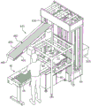
FIG. 1 is a perspective view of a material handling apparatus;
FIG. 2 is a plan view of the material handling system shown in FIG. 1;
FIG. 3 is a side view of one side of a track of the material handling system shown in FIG. 2;
FIG. 4 is a perspective view of a standby docking station of the material handling system of FIG. 1 with a recirculation system;
FIG. 5 is a side view of a material handling apparatus with the docking station and recirculation system shown in FIG. 4;
FIG. 6 is a plan view of a material handling system with the import station and recirculation system of FIG. 4;
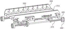
FIG. 7 is a top perspective view of a vehicle of the apparatus of FIG. 1;
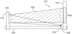
FIG. 8 is a front view showing the front of the object sensing device;
FIG. 9A depicts a linear array of photodetector elements and light energy collimated light sources mounted on a common support structure and forming part of the object sensing device of FIG. 8;
FIG. 9B depicts the mirrors aligned with the common support structure of FIG. 9A;
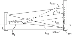
fig. 10A is a front view of an object sensing device that detects opaque objects as the objects traverse a detection plane defined by the propagation of collimated light energy in a direction transverse to the object transport path.
Fig. 10B is a front view of an object sensing device detecting an object having at least one light or light refraction as the object traverses a detection plane defined by the propagation of collimated light energy in a direction transverse to the object transport path.
FIG. 11 is a perspective view of an alternative tool of the material handling system;
FIG. 12 is an electrical schematic diagram depicting a circuit including a phototransistor and state sensing logic operative to signal a change in sensed state when an object passes through the detection plane of one of the object sensing devices of FIGS. 8-11;
FIG. 13 is a schematic front view of an alternate sorting location operable in the apparatus shown in FIG. 1; and
fig. 14 is a schematic side view of the sorting position shown in fig. 13.
Detailed Description
Some portions of the detailed descriptions which follow are presented in terms of operations on binary digital signals stored within a memory of a particular apparatus or special purpose computing device or platform. In the context of this particular specification, the term specific apparatus or similar term includes a general purpose computer once it is programmed to perform particular functions pursuant to instructions from program software. In this case, the operations or processes involve physical manipulation of physical quantities. Usually, though not necessarily, such quantities may take the form of electrical or magnetic signals capable of being stored, transferred, combined, compared, and otherwise manipulated. It has proven convenient at times, principally for reasons of common usage, to refer to these signals as bits, data, values, elements, symbols, characters, terms, numbers, labels, or the like. It should be understood, however, that all of these and similar terms are to be associated with the appropriate physical quantities and are merely convenient labels applied. Unless specifically stated otherwise, as apparent from the following discussions, it is appreciated that throughout the specification discussions utilizing terms such as "processing," "computing," "calculating," "determining," or the like, refer to the action and processes of a specific apparatus, such as a special purpose computer or a similar special purpose electronic computing device. In the context of this specification, therefore, a special purpose computer or a similar special purpose electronic computing device is capable of controlling or transforming signals, typically represented as physical electronic or magnetic quantities within memories, registers, or other information storage devices, transmission devices, or display devices of the special purpose computer or similar special purpose electronic computing device.
Reference will now be made in detail to exemplary embodiments of the invention, examples of which are illustrated in the accompanying drawings. Wherever possible, the same reference numbers will be used throughout the drawings to refer to the same or like parts.
Referring now to fig. 1-3, an apparatus for sorting articles is generally indicated at 10. The apparatus 10 includes a plurality of vehicles 200 that travel along the track system 100 to transport items to a plurality of destinations or sorting locations, such as output bins 190. The articles are loaded onto the carriers at the loading station 310 such that each carrier receives the articles to be delivered to the sorting location. The docking station 50 continuously delivers items to the loading station 310. One or more characteristics of each article are used to control the handling of the article as the vehicle moves along the track 100 to the output bin. The characteristics of each item may be known from each item or the system may acquire the characteristics of the items as they are processed by the system. For example, the docking station 50 may include one or more scanning elements for detecting one or more characteristics of the item.
From the loading station 310, the vehicle 200 travels along the track 110 to a destination. The rails may include a horizontal upper rail 135 and a horizontal lower rail 140, which operate as return legs (return legs). A plurality of parallel vertical track legs 130 may extend between the upper track and the lower return leg. The output bins 190 may be arranged in columns between the vertical rail legs 130.
The vehicle 200 is a semi-autonomous vehicle having an onboard power source and an onboard motor to drive the vehicle along the track 110. The carrier may include a loading/unloading mechanism 210, such as a conveyor, for loading and unloading articles onto and from the carrier.
Since the system 10 includes multiple vehicles 200, the positioning of the vehicles is controlled to ensure that different vehicles do not collide with each other. In one embodiment, the system 10 uses a central controller 350 that tracks the position of each vehicle 200 and provides control signals to each vehicle to control the travel of the vehicles along the guideway. The central controller 350 may also control the operation of various components (e.g., the door 180) along the track.
The following description provides details of the various elements of the system, including the docking station 50, the track system 100, and the vehicle 200. The manner in which the system operates will then be described. In particular, the manner in which the articles are transported may be controlled based on characteristics of the articles.
Guiding station
At the import station 50, items are introduced into the system by loading the items onto the vehicles 200 in succession. Since the characteristics of the article can be used to control the operation of the vehicle, the system needs to know the characteristics. In one example, the characteristics may be stored in a central database so that the characteristics become known and the system tracks the progress of the item so that the identity of the item is known when it arrives at the docking station 50. In this way, since the identity of the item is known, the system 10 can retrieve data stored in the database regarding the characteristics of the item. Alternatively, the items are scanned at the import station 50 to identify one or more characteristics of each item.
In one embodiment, each item is manually scanned at the import station to detect one or more characteristics of the item. These features are used to determine the identity of the item. Once the item is identified, various characteristics of the item may be retrieved from the central database, and the item may then be processed based on the known characteristics of the item. For example, the docking station 50 may include a scanning station 80 that scans a product code (e.g., a bar code). Once the product code is determined, the system will retrieve information about the product from the central database. This information is then used to control further processing of the article, as discussed further below.
In a second embodiment, the item is scanned at the import station 50 to detect various physical characteristics of the item. For example, the docking station 50 may measure a characteristic of the item, such as a length, height, and/or width. Similarly, the weight or shape of the article may be detected. These features may be detected manually or automatically at the import station. For example, a series of sensors may be used to detect the length of an item, and a scale may be used to automatically weigh the item. Alternatively, the operator may analyze each item and enter information about each item through an input mechanism (such as a mouse, keyboard, or touch screen). For example, the systemA touch screen may be included that includes one or more questions or options. One example is the packaging: whether the articles in the plastic bag are blister packs or loose Whether the article is flat, cylindrical or round
 The system may include default features such that if a component has a feature that is different from the default value, the operator need only identify the feature of the component. For example, the default feature of the item may be flat or rectangular. If the article is circular (e.g., spherical or cylindrical), the operator inputs information indicating that the article is circular, and the article may then be processed accordingly. Based on the detected information, the item is processed accordingly.
As described above, the input station may use a variety of configurations, including manual or automatic configurations or a combination of manual and automatic functions. In a manual system, an operator enters information for each item and the system transports the item accordingly. In an automated system, the input system 50 includes elements that scan each item and detect information about each item. The system then transports the item according to the scanned information.
In an exemplary manual configuration, the input system includes a workstation having a conveyor, an input device (such as a keyboard), and a monitor. The operator reads information about the item (e.g., an ID tag), enters the information on the tag into the system using a keyboard or other input device, and places it on the conveyor. The conveyor then transports the article to a loading station 310. For example, an operator may read information marked on an item with the eyes, or the operator may use an electronic scanner (e.g., a bar code scanner) to read a bar code or other marking on the item. Sensors positioned along the conveyor may track the component as the conveyor transports the item toward the loading station.
Alternatively, as shown in FIGS. 1-4, the import station 50 can include a scanning station 80 for automatically detecting characteristics of the item. In particular, the docking station 50 may include an input conveyor 55 for receiving the items and conveying the items to the scanning station 80, the scanning station 80 being operated to detect one or more physical characteristics of the items. From the scanning station 80, the infeed conveyor 70 delivers the item to the loading station 310 where it is loaded onto one of the carriers 200 or transferred to a reject bin 325.
The input conveyor 55 may be any of a variety of conveying devices designed to convey articles. In particular, the input conveyor may be designed for receiving articles dropped on the conveyor. For example, the input conveyor belt 55 may be a horizontal conveyor belt or a horizontal roller bed formed by a plurality of generally horizontal rollers that are driven to advance articles along the conveyor away from the rollers.
The input conveyor 55 may be configured such that an operator may select an article from a portion of articles located proximate to the input conveyor. For example, a separate supply conveyor may transport a steady stream of articles to the docking station 50. The operator may continuously select items from the supply conveyor and place the items on the input conveyor 55. Alternatively, large containers filled with articles, such as boxes or other containers, may be placed adjacent the input conveyor 55. The operator may select one article at a time from the supply bin and place each article on the input conveyor. Still further, the infeed conveyor 55 may be used in conjunction with a feed assembly that continuously feeds articles onto the infeed conveyor. For example, the supply conveyor may convey a continuous stream of articles to the infeed conveyor 55. The input conveyor may include a sensor for sensing when an article is being conveyed off the input conveyor. In response, the system may control the operation of the supply and infeed conveyors 55 to drive articles from the supply conveyor forward onto the infeed conveyor. In this manner, articles may be manually conveyed by an operator onto the input conveyor or automatically conveyed onto the input conveyor by a separate conveyor mechanism that is operable.
The import station may include a scanning station 80 for detecting one or more characteristics of each item prior to being loaded onto the vehicle for transport or sorting.
Various elements may be detected to evaluate the manner in which the article is processed. For example, it is often necessary to identify the item so that the system can determine which location or bin to transport the item. This is typically done by determining the unique product code of the item. Thus, if the system is able to identify the item using product marking or other indicia, the system may electronically mark the item as acceptable, enabling sorting. For example, an operator may read a product identification code on an item and enter the product code into the system using an input mechanism (e.g., a keyboard). If the product code entered by the operator corresponds to the correct product code, the item is acceptable and can be sorted. Alternatively, if the product code entered by the operator is incorrect or if the product code does not correspond to the identified item, the system may electronically mark the item as being rejected.
Similarly, the system may include a scanning element for scanning product identification indicia on the product. For example, the item may be marked with one or more of a variety of indicia, including but not limited to a machine-readable optical label such as a bar code (e.g., a QR or UPC code), a printed alphanumeric character, or a unique graphical identifier. The scanning station 80 may include a scanner or reader for reading such indicia. For example, a bar code reader, optical reader, or RFID reader may be provided to scan an item to read an identification mark.
The reader may be a hand-held device that an operator can manually operate, such as a hand-held laser scanner, CCD reader, bar code reader, or camera-based detector, which scans an image of the item and analyzes the image data to attempt to identify the product identification indicia. In this manner, an operator may manipulate the article and/or the detection device to scan the identifying indicia on the article. Alternatively, the scanner or reader may be a built-in scanner, such as any of the above devices built into a docking station, such that the item is simply conveyed over, across, or past the built-in reader, which reads the product identifying indicia. With this arrangement, an operator may pass an item through the scanner, or an item may automatically pass through the scanner.
Once the product identification indicia is determined (either manually or automatically), the system retrieves information about the product and then controls further processing of the item in accordance with the information stored in the central database.
As can be seen from the foregoing, a variety of different input mechanisms may be utilized to attempt to determine a product identification indicia on an item. In an example of the present invention, the scanning system 80 includes one or more optical readers operable to scan the item to obtain optical image data of the item. The system then processes the optical image data to detect the presence of the product identification indicia. If a product identification tag is detected, the system analyzes the tag to determine a product identification number or code.
For example, as shown in the embodiments of fig. 1-2 and 4, the scanning station 80 may include a plurality of optical imaging elements 85, 88, such as digital cameras, disposed along the infeed conveyor 70. The imaging elements are spaced apart from each other and are disposed about the infeed conveyor such that the imaging elements can scan the sides of the articles as they are conveyed toward the loading station 310. Specifically, the scanning station 80 includes one or more cameras 85 directed along a horizontal axis to scan the front and back of the article. In particular, the scanning station may include a plurality of imaging elements 85 disposed along the leading edge of the infeed conveyor and a plurality of imaging elements disposed along the trailing edge of the infeed conveyor. Additionally, the scanning station 80 may include one or more cameras 88 directed along a vertical axis to scan the top of the items as they are conveyed along the infeed conveyor 70. In addition, other imaging elements may be provided to scan the front and back of the article as it is carried by the infeed conveyor 70. In addition, the infeed conveyor 70 may include a transparent surface through which the articles are conveyed so that the bottom surfaces of the articles may be scanned by the inspection station. In this way, the scanning station may include a series of sensors, reading elements, scanning elements or detectors arranged around the path of movement so that the scanning station may automatically scan the item for identification indicia as it is transported along the path.
As described above, the scanning station 80 may analyze each item in an attempt to find a product identification indicia to identify the item based on the indicia. If the product identification indicia is determined, the system may determine the destination of the item, and the item may be electronically flagged as eligible for sorting. Similarly, parameters of how the vehicle should handle the item may also be determined based on information of the product code stored in the database. Conversely, if the product identification indicia of an item is not determined, the item may be electronically flagged as being out of sort.
In addition to analyzing the item for product indicia, the scanning station 80 may also include one or more elements operable to evaluate, analyze, or measure physical characteristics of the item to determine a treatment regimen for the item. For example, the scanning station 80 may include a scale for weighing the item. If the detected weight is greater than the threshold, the system may electronically flag the item as requiring some processing during subsequent processing. For example, if the weight exceeds a threshold, the system may control subsequent processing to ensure that the item is not unloaded into the destination bin where the fragile item has been placed. Alternatively, if the weight exceeds a threshold (which may be different than the threshold described above), the item may be marked as not eligible for sorting. Similarly, the sorting station 80 may include one or more detectors for measuring a linear measurement of each item. For example, the sorting station may measure the length, width, and/or height of each article. If one of the measurements exceeds a predetermined threshold, the system may electronically flag the item as requiring special handling during subsequent processing. The system may use any of a variety of elements to measure one or more linear dimensions of an item in the scanning station. For example, the system may use beam sensors (such as an I/R emitter and an opposing I/R detector) to detect the leading and trailing edges of the article. Based on the known speed of the infeed conveyor 70, the length of the article may be determined. Similarly, the beam sensor may be oriented in a generally horizontal direction that is spaced a predetermined height above the feed conveyor. In this manner, if an item breaks the beam sensor, the height of the item exceeds a predetermined threshold, causing the system to electronically mark the item as not eligible for sorting.
Further, the operator may use the input mechanism to identify the item as not meeting the sorting criteria due to the physical characteristic exceeding the predetermined threshold. For example, a scale may be marked on the input conveyor 55, and if the operator sees an article too long or too wide or too high, the operator may press a button indicating that the article has a physical characteristic that exceeds an acceptable threshold, causing the article to be electronically marked as not eligible for sorting. Similarly, a meter may be used to assess a physical characteristic of an article. One type of gauge is a groove or runner 60 having spaced apart sides. If the article does not match the dimensions of the chute walls, the article exceeds the allowable height, length or width and is to be electronically flagged as not meeting sorting conditions.
As described above, the scanning station 80 may be configured to analyze each item as it passes through the import station to detect various characteristics of the item. The system may make an authentication decision based on one or more characteristics detected or determined by the system. If the item is not eligible for sorting, the item may be directed to a reject zone 325 to await further processing.
Typically, the articles directed to the reject zone 325 are then manually processed. The operator picks up each item, identifies the item, and transports the item to the appropriate destination. Since manual handling of rejected items is time consuming and labor intensive, it is desirable to reduce the number of items directed to the reject area. Many items directed to reject area 325 may simply be erroneously scanned. Although the items cannot be sorted without sufficient identification information, the necessary information can be read in a subsequent scanning process.
Since some rejected items may need to be reprocessed, the information detected during the authentication process can be used to identify different categories of rejected items. The first type of rejected articles is rejected articles that are directed to a reject zone. In the following discussion, these items will be referred to as rejects. A second type of rejected articles is articles that do not meet sorting conditions but can be reprocessed. In the following discussion, these items will be referred to as reprocessed items.
The identification of whether an item is marked as rejected, reprocessed or sorted can be made based on various characteristics. In the present example, the identification of an item as rejected is based on the physical characteristics of the item. Specifically, if an article is rejected due to a physical characteristic (e.g., having a linear dimension, such as height, width, or length, that exceeds a threshold), the system electronically marks the article as a rejected article and directs the article to a reject zone 325 for manual processing. Similarly, if the scanning station includes a scale, the item is marked as a rejected item if the weight exceeds a weight threshold. On the other hand, if the item passes authentication based on physical characteristics but fails because the product identification element cannot be identified, the element is electronically flagged for reprocessing so that the item can be reprocessed in an attempt to read the product identification information. For example, depending on the orientation of the product, the imaging elements 85, 88 may not be able to properly read the bar code or other identifying indicia. However, since the scanning station has determined that the item meets the physical parameters for processing the item, the system may transport the item to an alternate output point, such as a bin for receiving the item that needs to be reprocessed. Items sorted or transported to the reprocessing bins may be manually returned to the docking station 50 so that the operator may reenter the items. Alternatively, the system may transport such items through the system to a reintroduction assembly, which may return the items to the entrance conveyor 55 of the docking station 50.
In this manner, the system 10 is operable to analyze the item to determine one or more characteristics of the item and to determine whether the item is in condition for transport or whether the item needs to be diverted to ensure that the item is not transported through the system by the vehicle. By doing so, the system can minimize damage to the item or can react if an oversized or overweight item is transported or attempted to be transported along the track 110 by one of the vehicles 200. Further, if the item meets the delivery conditions but does not meet the sorting conditions, the item may be delivered to a re-import station, as discussed further below, to attempt to re-process the item.
As can be seen from the foregoing, the docking station 50 may be configured with a variety of options. The options are not limited to those configurations described above and may include other features.
Additionally, in the foregoing description, the system is described as having a single docking station 50. However, it may be desirable to include multiple docking stations disposed along the system 10. By using multiple docking stations, the feed rate of the articles may be increased. Further, the import station may be configured to handle different types of items.
Referring to fig. 1-3, the docking station 50 includes a feed conveyor 70 that continuously delivers articles to a loading station 310. The loading station is a location along the track 110 that provides an access point for loading items onto the vehicle 200. At the loading station 310, the carriers are aligned with the infeed conveyor 70 so that articles unloaded from the infeed conveyor are received onto the carriers 200 at the loading station. After loading the item onto the vehicle, the vehicle exits the loading station 310 if the item is electronically flagged as eligible for delivery. Another carrier then moves to that location of the loading station to receive the next item. If the item is not electronically flagged as eligible for transport, the item is unloaded from the vehicle 200 into the reject bin 325.
The reject bin 325 is positioned so that it is opposite the infeed conveyor 70 of the docking station 50. In addition, reject box 325 is aligned with a carrier 200 waiting at loading station 310. In this manner, a clear path is provided from the docking station 50 to the reject bin 325 without requiring the vehicle to move along the track 110.
Re-import assembly
Referring to fig. 4-6, an alternative embodiment of the system is shown wherein the system includes an optional reintroduction system for items that are in transport condition but not in sorting condition. In fig. 4-5, the details of the import station 50 and the reintroduction system are shown without showing the details of the sorting station 100, such as the output bin 190 and the rail system 110. An item meeting the delivery criteria may exit the loading station 310 and be delivered to a re-directing station or sorting station 100. Specifically, the vehicle carrying the articles in accordance with the transport condition moves up the track 110 to the upper track 135. If the item on the vehicle is marked for re-evaluation, the vehicle travels along the track to the re-docking station 430. The carrier 200 then unloads the items onto the reintroduction assembly 410, which transports the items back to the induct conveyor so that the items can be reprocessed by the induct assembly in an attempt to conform the items to the conditions for sorting.
The re-import assembly 410 includes a path between the track and the import station 50 to facilitate returning the re-evaluated items to the import station. The reintroduction component 410 includes any of a number of delivery mechanisms. The mechanism may be driven or static, motorized or non-motorized. However, in the present example, the reintroduction assembly 410 includes a downwardly inclined roller bed 440 so that the articles are easily rolled along the roller bed. Specifically, the roller bed 440 has an upper end at the reintroduction station 430. The reintroduction station 430 is positioned vertically higher than the lower end of the roller bed 440 so that gravity tends to force the articles along the roller bed as they are unloaded onto the upper end of the roller bed at the reintroduction station.
The reintroduction assembly 440 includes an edge guide 450 that protrudes upwardly from and extends along the edge of the roll bed. A transverse wall extends across the lower edge of the roller bed 440 between the edge guides to form an end wall 460 to keep articles from rolling off the end of the roller bed 440. One of the edge directors 450 has a terminal edge spaced from the end wall 460 forming an access opening 455 at the end of the roll bed.
The reintroduction assembly 410 extends from the track 110 to an area adjacent to the introduction station 50. Specifically, the end of the reintroduction assembly is located near the input conveyor 55, and more specifically, it is positioned so that the operator at the input conveyor can easily access the articles at the access opening 455 on the roller bed 440.
The docking station 50 may include a second scanning element for scanning the items to be reprocessed. For example, as described above, the scanning station 80 may include a series of imaging elements that scan an item to obtain image data. The image data is then analyzed to detect the presence of the product identifying indicia. The docking station 50 may also include a portable laser bar code scanner that an operator may use to scan a bar code on an item during reprocessing. In this way, the first detection element is used during the first process and the second detection element is used during the reprocessing.
The docking station 50 may also include an input mechanism that an operator may operate to indicate that the item is being reprocessed. For example, the operator may press a button before unloading an item from the reintroduction assembly 410 onto the input conveyor 55. The system may then mark the item as previously processed, such that if the system fails to confirm that the item meets the processing criteria at the second attempt, the item is marked as rejected rather than being marked again for re-evaluation. In this manner, articles having defects that prevent identification do not continue to circulate through the reintroduction assembly 410. Similarly, if a second scanning element is used during reprocessing, the use of the second scanning element may be used as a signal that the article is being reprocessed. In other words, the system may mark the item as being reprocessed while the item is being scanned using the second element.
As described above, the reintroduction assembly includes a roller bed 440 that uses gravity to return the articles to the docking station 50. It should be understood that alternative mechanisms may be used rather than just a roller bed. For example, a chute or a smooth plate may be used. Alternatively, a conveyor belt may be used in combination to drive the articles towards the introduction station. Additionally, in the above description, reintroduction component 410 is a substantially straight pathway. It should be understood, however, that the redirecting assembly includes a turn or angle such that the discharge end of the redirecting assembly is adjacent the input conveyor 55 at the docking station. Further, in fig. 4-5 and the above description, the docking station 430 is located in a column next to the load column 300. However, it should be understood that the reintroduction station 430 and the matched conveyor 440 may be located in other columns, including the loading column 300.
Sorting station
Articles meeting the conditions for sorting by the induct 50 are transported by the vehicles to the sorting station. Referring to fig. 1-6, the system includes a sorting station 100, such as a series of bins 190 for receiving articles.
The rails 110 include a horizontal upper rail 135 and a horizontal lower rail 140. A plurality of vertical legs 130 extend between the horizontal upper leg and the horizontal lower leg 140. During transport, the vehicle travels up a pair of vertical legs from loading station 310 to upper track 135. The vehicle then travels along the upper track until reaching the column with the appropriate bins or destinations. The vehicle then travels down the two front vertical posts and the two parallel rear posts until the appropriate box or destination is reached, and then unloads the items into the box or destination area. The vehicle then continues down the vertical leg until it reaches the horizontal lower leg 140. The vehicle then returns to the loading station along the lower track.
The rail 110 includes a front rail 115 and a rear rail 120. The front track 115 and the rear track 120 are parallel tracks that cooperate to guide the vehicle around the tracks. As shown in fig. 7, each vehicle includes four wheels 220: two front wheels 220A and two rear wheels 220B. The front wheels 220A travel in the front track, while the rear wheels 220B travel in the rear track. It should be understood that in the discussion regarding tracks, the front track 115 and the rear track 120 are similarly configured as opposing tracks that support the front wheels 220A and the rear wheels 220B of the vehicle. Thus, the description of a portion of a front rail or a rear rail also applies to the opposite front rail or rear rail.
Referring now to fig. 1-3, a load column 300 is formed near the output end of the docking station 50. The loading column 300 is formed by a pair of front vertical rails 305a, 305b and a corresponding set of rear vertical rails. Loading stations 310 are disposed along the loading column. The loading station 310 is positioned along the track with the vehicles 200 aligned with the discharge end of the infeed conveyor 70 of the docking station 50. In this way, articles from the import station may be loaded onto the carrier as they are conveyed from the input station toward the carrier.
The details of the track are substantially similar to the track described in us patent No.7,861,844. The entire disclosure of U.S. patent No.7,861,844 is hereby incorporated by reference into this application.
As described above, with reference to fig. 3, the track includes a plurality of vertical legs extending between the horizontal upper track 135 and the horizontal lower track 140. At each portion of the track, an intersection is formed where one of the vertical legs intersects one of the horizontal legs. Each intersection includes a pivotable gate having a smooth curved inner race and a flat outer race with teeth that mate with teeth of the drive surface of the track. The door pivots between a first position and a second position. In the first position, the door is closed such that the straight outer loop of the door is aligned with the straight outer branch of the intersection. In the second position, the door is opened such that the curved inner loop of the door is aligned with the curved branch of the intersection.
In the foregoing description, the sorting station 100 is described as a plurality of output bins 190. However, it should be understood that the system may include various types of destinations, not just output bins. For example, in some applications, it may be desirable to sort items to a storage area, such as an area on a storage rack. Alternatively, the destination may be an output device that transports the item to another location.
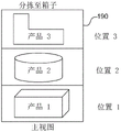
The output bin 190 may be a generally rectilinear container having a bottom, two opposing sides connected to the bottom, and a front wall connected to the bottom and spanning between the sides. The box may also have a rear wall opposite the front wall, connected to the base and spanning both sides. In this way, the boxes may be shaped like rectangular drawers that can be pulled out of the sorting station to remove items from the boxes.
The boxes in a column are vertically spaced apart from each other to form a gap between adjacent boxes. The larger gap provides more clearance space for the vehicle to unload an item into a lower box without the box above the box interfering with the item. However, larger gaps also reduce the number of bins or the size of bins (i.e., bin density). Thus, there is a trade-off between the size of the gap and the density of the boxes.
The carrier 200 unloads items into the box through the rear end of the box. Thus, if the rear side of the box is open, the vehicle can easily unload articles into the box through the rear open end of the box. However, if the bins do not have rear ends, the articles may easily fall out of the bins as they are pulled from the sorting rack. Thus, depending on the application, the box may have an open rear end or a closed rear end. If the rear end is closed, the rear wall may be the same height as the front wall. Alternatively, the rear wall may be shorter than the front wall to form an increased gap through which articles may be unloaded into the box. For example, the rear wall may be only half the height of the front wall. Alternatively, the rear wall may be between one quarter and three quarters of the height of the front wall. For example, the rear wall may be between half and three-quarters of the height of the front wall. Alternatively, the rear wall may be between one quarter and three quarters of the height of the front wall.
Alternatively, instead of having a fixed rear wall, the case 190 may have a movable or foldable rear wall. For example, the rear wall of the box may be vertically movable relative to the bottom of the box. In particular, the rear wall can be moved by pressing the wall downwards. The rear wall may move within a groove or slot formed in the side walls of the box so that pressing the rear wall downward moves the rear wall downward, thereby causing a portion of the rear wall to protrude below the bottom of the box. In such embodiments, the rear wall may be biased upwardly by a biasing element (such as a spring) so that the rear wall is easily held in an upward position with its bottom edge above the bottom edge of the case. The rear wall moves downwardly only in response to a force exerted on the rear wall in excess of the upward biasing force.
Another alternative case includes a foldable rear wall. Similar to the movable wall, the collapsible wall is moved downwardly by pressing downwardly against the collapsible wall. The collapsible wall may be formed in various configurations, such as an accordion or pleated configuration, such that when the wall is pressed downwardly, the wall collapses downwardly. The collapsible wall may include a biasing element that biases the wall upwardly to an extended position. For example, the biasing element may comprise one or more springs or resilient elements that bias the wall upwardly to an extended position.
As described above, the system is operable to sort various items to multiple destinations. One type of destination is a box; the second type is a shelf or other location where items can be stored; a third type of destination is an output device that can be used to transport items to different locations. The system may include one or more of these types or other types of destinations.
Vehicle with a movable handle
Each vehicle 200 is a semi-autonomous vehicle having an on-board drive system (including an on-board power supply). Each vehicle includes a mechanism for loading and unloading the items to be transported. An example of a vehicle that may operate with system 10 is shown and described in U.S. patent 7,861,844, which is incorporated by reference herein. However, an alternative vehicle 200 is shown in fig. 8. The vehicle includes additional sensors for detecting characteristics of the item being transported.
The vehicle 200 may include any of a variety of mechanisms for loading articles onto the vehicle and unloading articles from the vehicle into a case. In addition, the loading/unloading mechanism 210 may be customized specifically for a particular application. However, in this example, the loading/unloading mechanism 210 is one or more conveyor belts extending along the top surface of the vehicle. The conveyor belt is reversible. Driving the conveyor belt in a first direction to move the article toward the rear end of the carrier; driving the conveyor belt in a second direction moves the articles toward the front end of the vehicle.
A conveyor motor mounted on the underside of the vehicle drives the conveyor belt 212. Specifically, the conveyor belt 212 is wrapped around front rollers at the front edge of the vehicle and back rollers at the back edge of the vehicle. A conveyor motor is coupled to the front roller to drive the front roller to operate the conveyor belt.
The vehicle includes four wheels 220 for transporting the vehicle along the track 110. The wheels 220 are mounted on two parallel spaced apart axles 215 such that two wheels are disposed along the front edge of the vehicle and two wheels are disposed along the rear edge of the vehicle.
Each wheel 220 includes an external gear that cooperates with the driving surface of the track. The outer gear is fixed relative to a shaft on which it is mounted. In this way, the rotating shaft operates to rotate the gear. Thus, when the vehicle moves vertically, the gear cooperates with the drive surface of the track to drive the vehicle along the track.
The vehicle includes an onboard motor for driving the wheels 220. More specifically, a drive motor is operatively connected to the shaft to rotate the shaft 215, which shaft 215 in turn rotates the gear 222 of the wheel.
Items on top of the vehicle may easily fall off the vehicle as it travels along the track, especially as the vehicle accelerates and decelerates. Thus, the vehicle may include a locator to secure the component to the vehicle during transport. The retainer may be a hold down that clamps the article to the top surface of the vehicle. For example, the positioner may comprise an elongate pivotable arm. A biasing element (e.g., a spring) may bias the arm downward against the top surface of the retainer.
Alternatively, the system may secure the items to the vehicle 200 by controlling the operation of the vehicle rather than using a positioner. For example, the vehicle 200 may include a plurality of sensors 230 spaced apart from one another across the width of the vehicle. In the embodiment shown in fig. 7, the sensors 230 are spaced along a wall 231 at the front edge of the vehicle. The wall may be an elongate member extending the width of the vehicle. The wall operates as a stop or restraint to limit articles from falling or being unloaded from the front edge of the vehicle. Similarly, the vehicle 200 may include a rear wall 232 that may extend the width of the vehicle. The rear wall 232 may operate as a stop or restraint to limit articles from falling or being unloaded from the rear edge of the vehicle. The vehicle may also include a plurality of sensor elements spaced apart from one another along a rear wall 232, similar to the sensor 230 shown on the front wall 231 in fig. 7. The sensor 230 may be any of a variety of sensors including, but not limited to, a photoelectric sensor (such as opposed to a through beam sensor or a retro-reflective sensor) or a proximity sensor (such as a capacitive, photoelectric, or inductive proximity sensor). The sensor may be used to detect the position of the article in the width direction of the vehicle. Specifically, the sensors may detect the proximity of an article to the front side 234 or the rear side 236 of the vehicle. Similarly, if the sensor 230 is a proximity sensor, the sensor may detect the proximity of an article to the front edge of the vehicle (i.e., front wall 231) and/or to the rear edge of the vehicle (i.e., rear wall 232). Further, the sensor may detect movement of the article on the vehicle such that the system may detect the direction in which the article moves as it moves on the vehicle.
Based on the signals from the sensors 230 regarding the position or movement of the article on the vehicle 200, the system may control the vehicle to reposition the article in an attempt to maintain the article within a desired location on the vehicle. For example, it may be desirable to keep the item centered on the top of the vehicle. The system may use any of a variety of control methods to control the position of the article on the vehicle. For example, as previously described, the carrier 230 may include one or more conveyor belts for loading and unloading items. In such a configuration, the article is placed on the conveyor belt, and the conveyor belt is thus operable to drive the article toward either the leading edge 234 or the trailing edge 236 based on signals received from the sensors. In one example, if the signal from the sensor indicates that the article is moving closer to the trailing edge than the leading edge, the controller may send a signal to a motor driving the conveyor belt such that the conveyor belt is driven in a first direction to drive the article toward the leading edge 234. Similarly, if the signal from the sensor indicates that the article is moving closer to the leading edge than the trailing edge, the controller may send a signal to a motor driving the conveyor belt such that the conveyor belt is driven in a second direction to drive the article in an opposite direction, thereby driving the article toward the trailing edge 236. The sensor provides continuous feedback so that the position of the article can be continuously monitored and adjusted toward the front edge or the back edge as the article moves. In this way, the system provides a feedback loop for adjusting the position of the item in real time to maintain the item within a desired area of the vehicle roof.
In addition, the system may monitor the position of the articles relative to the front and rear edges of the vehicle (such as walls 231, 231). In response to the detected position of the element, the system may control operation of the vehicle if the article is too close to the front edge or too close to the rear edge. In particular, the system may control acceleration and braking of the vehicle to attempt to move the article toward the leading or trailing edge based on the detected position. If the sensor 230 detects that the article is located closer to the leading edge than the trailing edge, the vehicle may accelerate (or may increase the acceleration) forcing the article toward the trailing edge. Alternatively, the vehicle may be decelerated to force the article toward the leading edge.
In addition to verifying or monitoring the location of the item on the vehicle, the sensor may also be used to detect one or more characteristics of the item. For example, the sensor may be used to detect the length, width of the article. The sensor may also be used to detect the general shape of the article. This information may be used in further processing of the item, as discussed further below.
As described above, the case 190 may include a movable or foldable rear wall. Thus, the vehicle may include a mechanism capable of exerting a downward force on the rear wall sufficient to overcome the biasing force holding the wall in the upper or vertical position. For example, the vehicle may include a retractable element, such as a pin or rod. The pin may extend laterally away from the vehicle as the vehicle approaches the target delivery box, such that it extends beyond the rear wall of the target box. As the vehicle approaches the box, the extended pin engages the upper edge of the rear wall of the box. The downward drive vehicle drives the pin downward against the rear wall. The system may control the vertical position of the vehicle to control the distance the vehicle pushes or folds the rear wall rearward. After the carrier unloads the article into the box, the retractable element may retract, thereby releasing the rear wall such that the biasing element moves the rear wall upward to the upper position.
The vehicle 200 may be powered by an external power source, such as contacts along a track, providing the power required to drive the vehicle. However, in the present example, the vehicle includes an onboard power supply that provides the power required to drive the motor and the conveyor motor. Additionally, in examples of the invention, the power source is rechargeable. Although the power source may include a power source, such as a rechargeable battery, in an example of the invention, the power source is comprised of one or more ultracapacitors.
As discussed further below, the vehicle also includes a processor for controlling operation of the vehicle in response to signals received from the central processor. Additionally, the vehicle includes a wireless transceiver so that the vehicle can continuously communicate with the central processor as it travels along the track. Alternatively, in some applications, it may be desirable to incorporate multiple sensors or indicators disposed along the track. The vehicle may include a reader for sensing the sensor signal and/or the indicator, and a central processor for controlling operation of the vehicle in response to the sensor or indicator.
Edge sensing system
As described above, the system 10 may include one or more components for detecting items on a vehicle. It may also be desirable to detect the leading and trailing edges of an article as it is loaded onto or unloaded from a vehicle. Thus, each vehicle may include one or more sensors to detect items on the vehicle.
In the embodiment shown in fig. 7, each vehicle includes a plurality of detectors 230 that detect articles on top of the vehicle (i.e., on the surface of the conveyor belt 212). One of the sensors 230A may be disposed near the leading edge 234 to detect items as they are loaded onto or unloaded from the leading edge. Similarly, one of the sensors 230B may be disposed near the rear edge 236 to detect items as they are loaded onto or unloaded from the rear edge. For example, the front sensor 230A may be a beam-blocking sensor such that the beam is interrupted when an object passes in front of the beam. When an article is loaded onto the vehicle 200, the leading edge of the article will be interrupted by the light beam, indicating that the leading edge of the article is on the vehicle. The item continues to block the front sensor 230A until the back edge of the item passes the front sensor 230A. After the trailing edge of the article passes the front sensor 230A, the front sensor will no longer detect the article, indicating that the article is loaded onto the vehicle. After the trailing edge passes the front sensor 230A, the conveyor 212 may continue to drive the article toward the trailing edge 236 to ensure that the article is centered along the width of the carrier. Similarly, the front sensor 230A may detect the front and rear edges of the article as it is unloaded from the front 231 of the vehicle. Detection of the trailing edge by the front sensor 230A may be used to signal that the article has been unloaded from the vehicle. The vehicle is then prompted to advance away from the discharge position. The above description of using the front sensor 230A to detect the front and rear edges of an article as it is loaded onto or unloaded from the front edge is similar to using the rear sensor 230B to detect the front and rear edges of an article as it is loaded onto or unloaded from the rear edge of a vehicle.
In the foregoing description, the sensor 230 detects items as they are loaded onto and unloaded from the leading edge 234 or trailing edge 236 of the vehicle. In some applications, it may be desirable to incorporate a sensing assembly to detect a greater variety of items. For example, when using a beam-blocking sensor, it may be difficult to detect the leading or trailing edge of an item if the item is very thin or if the item is transparent or translucent. Accordingly, the system may include an alternative sensing device, labeled 500, shown in fig. 8-12. Although the sensing device is described in connection with a vehicle of the material handling system 10, it should be understood that the sensing device 500 may be used in connection with other aspects of the system, such as detecting items as they pass through a docking station. Furthermore, the sensing device 500 described below may find further application in areas of research outside the area of material handling, including but not limited to, such as mail handling or document handling.
Embodiments of edge sensing assemblies include systems and methods for assisting in reliably and accurately detecting events (e.g., leading edge surfaces and/or trailing edge surfaces of objects supported by an underlying conveyor surface passing through a detection plane). In accordance with one or more embodiments, a detection plane is defined by optical energy, emitted by a laser and collimated by a lens system to form a diverging constant width beam that propagates within the detection plane. The linear array of photodetectors is kept aligned with the lens system so that collimated light can be projected at non-normal incidence angles through any object in the detection plane.
Conventional "cross-beam" sensors may have difficulty detecting transparent objects, thin objects, and/or irregularly shaped objects. However, according to one or more embodiments consistent with the present disclosure, such objects can be easily sensed by changes in the intensity of optical energy detected by one or more photodetectors in the array. For example, if an opaque object is present, the light energy may be absorbed, thereby enabling the at least one photodetector to sense a decrease in light intensity. Alternatively, for objects comprising light-transmissive portions and/or packaging, some light may pass through and some light may be reflected or refracted, such that the at least one photosensor senses a less pronounced but still detectable decrease in light intensity. With a suitably arranged lens system and photodetector, even relatively thin (about 0.05 mm) objects can be reliably detected.
Various embodiments of systems and methods for detecting the passage of a leading edge surface and/or a trailing edge surface of an object supported by a lower conveyor surface through a detection plane are described. In the following detailed description, numerous specific details are set forth in order to provide a thorough understanding of the claimed subject matter. However, it will be understood by those skilled in the art that claimed subject matter may be practiced without these specific details. In other instances, methods, devices, or systems that would be known by one of ordinary skill have not been described in detail so as not to obscure claimed subject matter.
The edge sensing assembly 500 includes one or more emitters 504 for emitting light sources and one or more detectors 506 for detecting the emitted light. At least one emitter 504 is located below the surface S supporting the article. For example, in the embodiment shown in FIG. 10, emitter 504 is vertically spaced from the location of surface S such that the emitter is below the plane of surface S. In this example, the plane of the surface S is a horizontal plane, and the emitter is below the surface. In this way, the emitted light from the emitter 504 is projected upwards at an angle relative to the plane of the surface S. By projecting the emitted light at an angle relative to the surface S, the object can thus have a larger surface to receive the projected emitted light than if the light were emitted parallel to the surface S. For example, in the example of a sheet of paper placed on surface S, if the light from the emitter is projected parallel to surface S, only the sides of the paper reflect or block the emitted light from the emitter. Since the sides of the paper are thin (e.g., 0.05 mm), it is difficult or impossible to detect with an emitter that projects light parallel to the surface S. However, by lowering the emitter below S and projecting light at an angle to the surface S, the entire width of the paper can reflect light from the emitter.
Referring now to fig. 8, an object sensing assembly 500 is adapted to sense when a boundary surface of an object (e.g., a leading or trailing edge of an object placed on an underlying object support surface) has entered a detection plane or "curtain" 502 of light (also referred to as an emitter) emitted by the emitter 504. A linear array of photodetector elements 506, generally indicated at 508, is aligned with the emitter 504 such that the emitted light projects each photodetector with non-decreasing intensity unless an object is inserted into the detection plane 502.
In some embodiments, emitter 504 is a solid state laser that emits a coherent light beam in the wavelength range visible to the human eye. To effectively and reliably detect its output, the emitter 504 may be a laser capable of emitting light at or near the peak sensitivity of the photodetector 506. According to one embodiment, the photodetector is a phototransistor, which may have a spectral range of sensitivity in a frequency range between 350 and 950nm and a sensitivity peak of 560nm, for example. One such phototransistor is SFH3710 manufactured by Osram Opto Semiconductors GmbH (Osram @ Opto-electronic Semiconductors ltd), renberg, germany. It should be noted, however, that other photodetectors (e.g., photodiodes) may be employed in place of the phototransistors. Ambient light can be prevented from affecting the photodetector sensitivity by placing a band pass filter on the array 508, if appropriate, to prevent light outside a narrow range centered around the sensitivity peak from reaching the photodetector.
For example, from the perspective of FIG. 8, the assembly can detect objects having a thickness of between 0.05mm (i.e., the thickness of a single sheet of paper) and about 10cm and a width of about 7.5cm to about 30.5cm using a light curtain 502 having a width of about 25-35cm and a height of about 10-20 cm. This detection can be achieved with a 1mW laser with integrated collimating optics. Such a laser can project 5cm of light with a width of 1-2mm when the fan angle is 20 degrees and the beam divergence is less than 2 milliradians (mRads). When placed near but slightly below the discharge end of the object support surface, the light sources 504 and array 508 form a detection plane that is transverse and perpendicular to the plane defined by the object support surface. In some embodiments, the object-supporting surface may be a moving surface of a conveyor belt. In other embodiments, the object support surface may be a fixed or inclined table top.
Depending on the components forming the collimating lens system, the light intensity within ray 550 in FIG. 9A is uniform across all of the photodetectors 506 when no object is present to interfere with the integrity of the light sheet 502. Alternatively, the intensity on the light sheet 502 may vary according to a Gaussian or other predictable distribution function. In either case, embodiments consistent with the present disclosure are configured to detect changes in the intensity of light received on any of the photodetectors 506 as an object passes through (or exits) the light sheet 102. That is, when light energy above the sensitivity threshold is absorbed, reflected, or refracted by an object on the surface S, the output of at least one photodetector 506 of the array 508 will signal a state change.
In the illustrative example where the sensing device 500 forms part of a material handling system, the detected change in photodetector state can be used to confirm that the object was successfully moved to a storage or packaging location, successfully retrieved from a storage location or a picking location. In contrast, the absence of detection of a signal indicative of a change in state may also be used to control operation in a material handling system or other system. For example, after a predetermined "timeout" interval, no recorded state change may be used as part of an alarm sequence (e.g., triggering an audible or visual alarm sent to an operator).
One possibility to increase the coverage of the light detected by the detector 506 is to use a complementary photo detector array and light source pair in order to increase the coverage of the light curtain. However, in the arrangement of fig. 8, it can be seen that the mirror 516 can be used to fold the optical path, thereby obtaining comparable results. In such an arrangement, the photodetector elements 506 of the array 508 are optionally mounted together with the emitter 504 on a first rigid support 510 to form an integrated emitter/detector assembly 512. The mirror 516 may be mounted to a second rigid support 518. The first and second supports 510, 518 may be rigidly connected, such as by a support shaft 520 extending between the two supports. The shaft 520 may be resiliently biased to maintain the orientation of the light sheet 502 relative to the surface S, while also allowing for instantaneous angular reorientation of the light sheet in response to translation of the surface S.
In some embodiments, the photodetector elements 506 and the light sources 504 may be mounted on a common substrate 524, e.g., as a printed circuit board. The collimated diverging beam emitted by lens 522 of emitter 504 is reflected by surface 530 (FIG. 9B) of mirror 516 and forms a projection line or projection area 550 on array 508 of photodetectors 506. In an exemplary application, where it is desired that the object to be treated have a height that may vary from less than 1mm to 20cm or more, the light ray 550 may have a width W, for example, from about 1mm to about 5mm, and a length L, for example, about 10-20cm long. In the exemplary embodiment, array 508 is arranged to cover the entire length of light L.
To accommodate the detection of very thin objects, those photodetectors 506 of the array that are closer to the object-supporting surface S may be spaced less than those that are further from the object-supporting surface. In the exemplary embodiment of FIG. 9A, the spacing d between the four photodetectors at the lowest is1May be about 1-5mm with a spacing d between the remaining photodetectors2Is about 10-15 mm. Of course, this arrangement is described here only by way of illustrative example. The present invention also contemplates arrangements such as those in which the photodetector spacing between at least a subset of the photodetectors monotonically increases with distance from the object support surface, and/or arrangements in which uniform photodetector spacing is used. It can be said that the number and spacing of the photodetectors can be varied without departing from the spirit and scope of the present disclosure.
Fig. 9B depicts a mirror mounted on an arm 518 and aligned with the support 510 of fig. 9A to form an object sensing device 512, such as the one shown in fig. 8. As seen in fig. 9B, the mirror 516 defines a substantially flat reflective surface 530 and is secured to the second rigid member 518. In addition, as shown in FIGS. 8, 9A and 9B, the curtain height of the light entrance mirror 516 is substantially less than the height (L) of the array 508. Thus, the height of the mirror 516 is substantially less than the height (L) of the array 508.
FIG. 10A depicts the detection of a light-tight object O using a sensing device such as that shown in FIG. 8 as the object moves along an object transport path (e.g., on a lower support surface S) and through a light curtain (or "detection surface") defined by propagating collimated optical energy in a direction transverse to the object transport path1. As seen in fig. 10A, light emitted by the optical energy source 504 is collimated by a lens structure including a lens 522. In this example, an object O1Is of such a height and width that light from emitter 504 is reflected by mirror 516 and detected by detectors 506-2 through 506-10. However, the object O1Absorbs most or all of the light energy that will reach the photodetector 506-1 such that the detector 506-1 cannot detect light or such that the light detected by the detector 506-1 is below a threshold.
As explained in more detail below, the decrease in intensity at the photodetector 506-1 can be processed by suitable sensing logic as a change in state (e.g., a logical "1") indicative of an object passing through a detection plane defined by the generated light curtain 502. Similarly, when the object O1When no portion of the light is within the light curtain, a second state transition occurs when the intensity of the light energy received at the photodetector 506-1 returns to an earlier state (e.g., a logic "0").
FIG. 10B depicts the object O as it is2For an object O comprising at least one photorefractive or reflective portion, while moving along a transport path transverse to a detection plane defined by the propagation of collimated light energy2Detection of (3). For example, the object O2May be an article such as a block contained in a transparent or translucent package that extends beyond the blockVolume of the shape. Such objects may have opaque portions (e.g., the block) and transparent or reflective portions (e.g., a package enclosing the block).
Some of the light emitted by the emitter 506 will pass through the object O2And in configurations where the emitter is parallel to the surface S, light passes through the transparent or translucent portion so that the system does not detect the object. In this example, the light emitted by the emitter 506 is transverse to the supporting object O2So as to pass through the object O2May be refracted such that light does not illuminate the detector array 508. For example, referring to FIG. 10B, light is emitted (e.g., along ray B)Incident lightPropagating emitted light) will be projected at an oblique (non-normal) angle to O2Of (2) is provided. Some incident light BIncident lightCan be projected on the object O2And then reflected and/or refracted. According to the object O2Some or all of the reflected incident light may be directed away from the photodetector, as in ray BReflection 2And if all light has propagated through the object O2(e.g., along ray BPropagation) Propagation or the absence of said object at all, other parts of the light (e.g. light B)Reflection 1) May be reflected into a different photodetector than it otherwise would reach. In this way, when the translucent or transparent portion of the object refracts light away from the array, the array will detect a change in the light from the emitter, so the system will detect the object.
As previously described, the edge detection assembly 500 may be incorporated into a vehicle used in the material handling system 10 described above. For example, referring to fig. 11, an alternative vehicle 600 is shown. The vehicle 600 is substantially similar to the vehicle 200 described above, but the vehicle 600 includes one or more edge detection assemblies 602, 604 similar to the edge detection assembly 500 described above.
Each vehicle 600 may include a single object sensing device for sensing object movement in a single direction along the transport path. Alternatively, as shown, each vehicle 600 may include a pair of object sensing devices in the form of detection assemblies 602 and 604. Each vehicle may also include one or more conveyors for conveying the objects while on the vehicle. The conveyor belt forms a generally flat surface or plane for supporting objects on the vehicle 600. For example, the conveyor 606 may be a conveyor belt. The first detection assembly 602 may be disposed near a rear edge of the vehicle 602 such that the emitter is below the upper surface of the conveyor belt 606. The detector of the detection assembly 602 may be located above the surface of the conveyor belt. Additionally, the detection assembly may be located near a rear edge of the conveyor such that the surface of the conveyor belt does not extend between the emitter and the detector of the detection assembly. In this manner, as the object passes over the trailing edge of the vehicle, the object will first pass between the emitter and detector arrays of the detection assembly 602. Similarly, when an object is discharged from the rear edge of the vehicle, if the leading edge extends beyond the end of the conveyor, the leading edge of the object will pass between the emitter and detector arrays of the detection assembly. Similarly, the front detection assembly 604 is located near the front edge of the vehicle such that the front detection assembly 604 detects the front edge of an object as it is loaded onto or unloaded from the front edge of the vehicle.
For example, as previously described in connection with assembly 500, detection assembly 602 may signal a first change in logic state when an object is being transport moved by conveyor 606 in a first transport direction "a" such that a leading edge of the object passes through a first light curtain detection plane of an edge sensing assembly. Such a signal would indicate that the leading edge of the article is being discharged from the trailing edge of the vehicle. Likewise, if the object continues to move in direction a by the conveyor 606 such that the trailing edge of the object is out of the first light sheet detection plane, the detection component 602 can signal a subsequent (e.g., second) change in logic state. Such a signal would indicate that the rear edge of the object is being unloaded from the rear edge of the vehicle, indicating that the article has been unloaded from the vehicle.
Similarly, the detection component 604 can signal a first change in logic state when the object is being transported in the second transport direction "B" by the conveyor 606 and its leading edge passes through the second light curtain detection plane of the edge sensing component 604. Likewise, if the object continues to move in direction B by the conveyor 606 such that the trailing edge of the object exits the second light sheet detection plane, the detection component 604 can signal a subsequent (e.g., second) change in logic state.
The vehicle 600 may include sidewalls sized and arranged to prevent translation of objects on the conveyor surface 605 as the vehicle moves along a travel path transverse to the conveyance path directions a and B. In some embodiments, movement of the conveyor 606 in the a or B direction is performed by a reversible electric motor 610, which reversible electric motor 610 uses a conveyor belt 612 to transfer power to a conveyor shaft 611. Similar to the operation of the vehicle 200 previously described, separate motors drive the rail-engaging wheels (e.g., 614a, 614b, 614 c) of the vehicle 600.
Fig. 12 is an electrical schematic diagram depicting a circuit 650, the circuit 650 including a photodetector and state sensing logic operable to signal a change in a sensed state when an object passes through a detection plane or light curtain in which a phototransistor is disposed, according to an exemplary embodiment of the present disclosure. In the exemplary embodiment of fig. 12, the photodetectors are implemented as NPN phototransistors PT1 through PT10 in respective common emitter amplifier circuits.
The output of each common emitter amplifier circuit is generated by connecting a respective resistor (R1-R10) between the voltage source VB and the collector pin of the associated phototransistor. The values of resistors R1-R10 are selected to set the detection threshold (e.g., to distinguish expected ambient light levels given an installation). The low value (several kiloohms) of the threshold resistor sets a high threshold level (i.e., low sensitivity) for incident light to exceed before switching occurs, while the high value sets a low threshold level (i.e., high sensitivity). For example, using an SFH3710 phototransistor manufactured by osram optical semiconductors ltd of rengen burg, with a voltage VB of about 3.0 to 3.5 volts, a circuit that is immune to noise or interference from ambient light sources (e.g., room lighting) can be produced when the resistance values of R1 to R10 are about 300 ohms under conditions typically applicable to an indoor warehouse environment. Additionally, or alternatively, a filter may also be used that limits the light reaching the phototransistor to a relatively narrow (e.g., +/-2 nm) passband centered at a selected wavelength within the sensitivity envelope of the phototransistor (not shown).
The sensing logic 652 comprises any arrangement capable of rapidly sensing the output of each photodetector and signaling and/or processing a change in state indicative of a light curtain shift. In one example consistent with the embodiment of FIG. 12, the output of each phototransistor circuit can be combined using combinational logic such that the output of the sense logic 652 changes state from "0" to "1" when the output of any one phototransistor is below the sensitivity threshold. When the outputs of all of the phototransistors return to "0", the sense logic 652 outputs a subsequent change in state from "1" to "0". In one embodiment, the sense logic 652 may comprise a field programmable gate array.
In other embodiments, the sensing logic may be implemented by a microprocessor that senses or samples the output of each respective photodetector during a respective clock cycle and initiates an action in response to any photodetector changing from a high state to a low state or from a low state to a high state, and in a subsequent cycle, when all photodetectors again all output a high state. In some embodiments, a vehicle (such as vehicle 600 of fig. 11) may include a microprocessor that not only monitors the sensing devices (such as 602 and 604), but also controls the movement of the conveyor 406 and the vehicle itself.
Embodiments consistent with the present disclosure may employ sensing arrangements, such as the apparatus 500 of fig. 8-10, and systems for conveying objects along a conveying path. Such systems define one or more object support surfaces, and may further include one or more object transport mechanisms each operable to move an object supported by the object support surface in at least one object transport direction. In some embodiments, the support surface may be defined by a surface of one or more belt conveyors, one or more roller conveyors, one or more inclined tables, or one or more fixed tables. Where a tilting table or stationary table is used, they may have perforations in fluid communication with a source of pressurized air to reduce friction during object transfer operations.
Transferring an object onto or from an object-supporting surface of a system constructed in accordance with embodiments of the present disclosure may be performed in a variety of ways. As an illustrative example, a pushrod or other structure may exert a positive force to move an object onto, through, and/or off of an object support surface. Alternatively, or in addition, the object support surface itself may be reoriented (e.g., tilted) by the object transport mechanism such that the object moves by gravity onto another object support surface or into a box or carton at the destination. By way of yet another example, the object transport mechanism may include a conveyor having, for example, a conveyor belt defining an object support surface. In such embodiments, the conveyor belt may be driven in a first direction to convey the object toward the first discharge end of the object conveying mechanism so that it may fall into, for example, a first waiting container. Similarly, the same conveyor belt may be driven in a second direction to convey the object toward the second discharge end of the object conveying mechanism so that it may fall into, for example, a second waiting container.
In some embodiments, one or more object support surfaces and optionally one or more object transfer mechanisms of the material handling system may be moved by the vehicle to an object transfer destination. In one embodiment, a conveyor equipped with a vehicle, such as vehicle 600 of fig. 11, may be used as part of a material handling system, such as a device for sorting objects into groups of "n" items. In one embodiment, "n" is equal to or greater than 1, and each group includes objects to be placed in a single shipping carton for shipment to a single customer as part of the order fulfillment process.
In some embodiments, the object transfer cycle is initiated when the leading edge of the object enters a detection plane formed by a sensing device, such as sensing device 500 of fig. 8-10, and the object transfer cycle ends when the trailing edge of the object exits the detection plane/curtain. Completion of each cycle constitutes confirmation that the object has been transferred from the object support surface of the vehicle 600 into one of the bins 119. The ability to accurately perform the inspection to complete each cycle for objects of different shapes, sizes, and optical characteristics allows each vehicle to return to the charging station and/or object transfer station 310 without delay due to inspection failure. Also, the risk of the vehicle leaving the destination close to one of the boxes 19 and/or leaving the loading station 130 before the transfer is completely completed is greatly reduced, irrespective of the shape and opacity of the objects involved.
Operation of
The system 10 operates as follows. The articles are processed at the import station 50 to identify characteristics of the articles that indicate the locations to which the articles should be sorted. As previously described, the items may also be processed based on their physical characteristics to determine whether the items are conditioned for transport by one of the vehicles. The central controller maintains data relating to various data to identify the destination bin or location of the item being processed.
As previously described, the docking station 50 may automatically or manually process the item. In the manual mode, the operator manually enters information about the article and then places the article on the conveyor. The system electronically tags the item with the sortation information and the conveyor conveys the item to the loading station. Alternatively, if the input system is an automated system, the item is automatically scanned to identify relevant classification features. For example, the input station may use a scanner, such as a bar code scanner, to read a bar code on the item, or the input station may include an imaging device, such as a high speed linear scanning camera in combination with an OCR engine, to read information on the item.
To prepare for receiving an article, the vehicle 200 moves along the track toward the loading station 310 in the loading column 300. When the vehicle 200 moves to a position at the loading station 310, the home sensor detects the presence of the vehicle and sends a signal to the central processor 350 indicating that the vehicle is located at the loading station.
Once the carrier is at the loading station, the input station delivers the item to the carrier. The loading mechanism 210 on the vehicle loads the items onto the vehicle as the items are transported onto the vehicle 200. Specifically, the input station delivers the item into contact with the conveyor belt 212 on the vehicle. The conveyor belt 212 rotates toward the rear side of the vehicle, thereby driving the articles rearward on the vehicle.
The operation of the conveyor is controlled by load sensors 260, 262. The forward load sensor detects the leading edge of an article as it is loaded onto the vehicle. Once the forward load sensor 260 detects the trailing edge of the article, the controller on the vehicle determines that the article is loaded on the vehicle and stops the conveyor motor. Additionally, the on-board controller may control the operation of the conveyor in response to signals received from the rear-facing sensor 262. Specifically, if the rearward sensor 262 detects the forward edge of the article, the forward edge of the article is adjacent the rear edge of the vehicle. To ensure that the articles do not protrude from the rear edge of the vehicle, the controller may stop the conveyor once the rear sensor detects the front edge of the article. However, if the rear sensor detects the leading edge of an item before the front sensor detects the trailing edge of the item, the controller may determine that the item is in problem (i.e., too long or two overlapping items are being sent to the vehicle.
After loading the articles onto the carrier, the carrier exits from the loading station. Specifically, once the onboard controller detects that the article is properly loaded onto the vehicle, the onboard controller sends a signal to start the drive motor 250. The drive motor 250 rotates the shaft, which in turn rotates the gear 222 on the wheel 220. The gear 222 engages the drive surface 156 of the vertical rail 305 in the loading train to drive the vehicle upward. Specifically, the gears engage the drive surface and operate as a rack and pinion mechanism, converting the rotational motion of the wheels into linear motion along the track 110.
Since the vehicle moves the load train up from the loading station, there is no need to determine the destination of the vehicle before the vehicle reaches the first door along the upper track 135. For example, if an automated system is used at the docking station 50 to scan and determine characteristics for sorting items, some processing time may be required to determine relevant characteristics and/or communicate this information with a central controller to receive destination information. The time it takes to transport an item onto a carrier and then transport the carrier up a loading column is often sufficient to determine the relevant characteristics of the item. However, if the characteristic is not determined by the time of arrival of the vehicle at the upper track, the system may conclude that the article is not in compliance with the sort condition and may direct the vehicle to the reintroduction station 430 to discharge the article onto the discharge assembly 410. From the re-introduction station 430, the vehicles travel down the second column to the lower track 140 and then return to the loading column.
Once the items meet the sorting criteria, the central controller 350 determines the appropriate bin 190 for the item. Based on the location of the bin of items, a route of the vehicle is determined. In particular, the central controller determines a route of the vehicle and communicates information to the vehicle about the bin to which the item is to be transported. The central controller then controls the doors along the tracks to direct the vehicles to the appropriate columns. Once the vehicle reaches the appropriate column, the vehicle moves the column down to the appropriate box. The vehicle stops at the appropriate bin 190 and the onboard controller sends an appropriate signal to the conveyor motor 255 to drive the conveyor belt 212, the conveyor belt 212 driving the articles forward to discharge the articles into the bin. Specifically, the top of the vehicle is aligned with the gap between the appropriate bin 190 and the bottom edge of the bin, which is just above the appropriate bin.
In this example, the orientation of the vehicle does not substantially change as the vehicle moves from horizontal travel (along the upper or lower track) to vertical travel (along one of the columns). Specifically, when the vehicle travels horizontally, two front gears 220 are engaged with the upper or lower horizontal rails 135 or 140 of the front rail 115, and two rear gears 220 are engaged with the corresponding upper or lower rails 135 or 140 of the rear rail 120. When a vehicle passes through the door and then enters the train, the two front gears engage with a pair of vertical legs 130 in the front track 115 and the two rear gears engage with corresponding vertical legs in the rear track 120.
The track allows all four gears to be positioned at the same elevation when the vehicle travels from a horizontal track to a vertical column or from vertical to horizontal. In this way, the vehicle does not drift or tilt as it changes between horizontal and vertical movement as it travels along the track.
Flow control
Since the system includes multiple vehicles 200, the system controls the operation of the different vehicles to ensure that the vehicles do not collide with each other. In the following discussion, this is referred to as flow control. An exemplary method for controlling flow is described in U.S. patent No.7,861,844.
In this example, some columns may have two vertical tracks 130 that are independent of adjacent columns. For example, the loading column 300 has two independent tracks that are not shared with adjacent columns. Thus, vehicles may travel on the load train regardless of the position of the vehicles in the trains next to the load train. Furthermore, as shown in fig. 5, it may be desirable to configure the columns next to the loading column so that it also has two independent vertical guide rails. In this way, the vehicles may be more free to travel up the loading column and down the adjacent column.
In the foregoing discussion, the sorting of articles has been described with respect to an array of bins disposed at the front of the sorting station 100. However, by installing a rear array at the rear of the sorting station, as shown in FIGS. 3-4, the number of bins in the system can be doubled. In this way, the carrier can transport items to bins on the front side of the sorting station by traveling to the bins and then rotating the conveyor on the carrier forward to eject the items into the front bin. Alternatively, the carrier may transport the items to the bins on the rear side of the sorting station by traveling to the bins and then rotating the conveyor on the carrier rearwardly to eject the items into the rear bins. In addition, the sorting station 100 is modular and can be easily expanded as desired simply by attaching additional sections to the left end of the sorting station.
Article feature based vehicle control
1. Vehicle motion profile
As previously described, one or more characteristics of the items transported by the vehicle may be detected or determined during processing. This detected information may be used to control further processing of the article. In particular, control of the vehicles between the loading station 310 and the destination box 190 may be altered in response to the detected information. More specifically, the movement of the vehicle along the track may be varied in response to the detected characteristic.
Various motion variables of the vehicle may be changed based on the detected information. The list of motion variables includes, but is not limited to: an acceleration curve (i.e., the speed at which the vehicle accelerates), a braking curve (i.e., the speed at which the vehicle brakes), and a turning speed (i.e., the speed at which the vehicle travels around a corner). Another way in which the vehicle may be controlled in response to the detected information is in which the article is ejected from the vehicle. In particular, the belt speed of the vehicle may be increased or decreased to vary the speed at which the articles are ejected.
For example, the system may have a default control curve for controlling the movement of the vehicle along the track. Under the default curve, the vehicle moves along the track at a first peak speed, accelerates at a first rate, and brakes at the first rate. Additionally, under the default motion profile, the vehicle has a first peak velocity when the vehicle travels around a horizontal to vertical or vertical to horizontal profile. The default curve may be applied to a variety of articles having a range of characteristics suitable for the default characteristic curve, such as flat articles having a reasonable weight (e.g., books, boxes weighing several ounces or more, etc.). However, if the system detects a different characteristic than the default characteristic curve, the system may change the control of the vehicle motion. In particular, the system may control the motion according to the second motion profile. For example, if the system detects that the element is cylindrical, the system may control the vehicle according to a motion profile that is different from the default profile. The vehicle may be accelerated more slowly than the default curve to reduce the likelihood of items rolling on the vehicle. Similarly, the vehicle may brake more slowly and may travel around corners at a slower rate to reduce the likelihood of items rolling on the vehicle.
As described above, control of the vehicle may be controlled according to a motion profile, and the motion profile may be varied based on one or more characteristics determined for the articles to be conveyed by the vehicle. It should be appreciated that the system may store a plurality of motion profiles, each controlling the movement of the vehicle along the guideway in accordance with a different parameter. Each motion profile may be associated with one or more characteristics of a particular item. In this way, various items having one or more shared characteristics may share the same motion profile. For example, all frangible non-circular articles may share the same motion profile, and all frangible circular or cylindrical articles may share the same motion profile.
In this manner, the system may dynamically control the motion of each vehicle based on one or more characteristics determined by each article carried by each vehicle. The characteristics may be determined by directly detecting the characteristics (scanning, weighing, measuring, etc.) or the characteristics may be stored in a central database and determined by identifying the item, for example by a product code. In addition to or instead of storing information about the characteristics of the item, the database may simply include data identifying a motion profile to be used for the item. In this case, the system or operator scans the item to detect a product identifying feature (e.g., a bar code or other identifying information). The motion profile of the vehicle is identified in a central database of the item, such that the system retrieves the vehicle motion profile data from the central database after identifying the item.
2. Vehicle destination control
As described above, the system may control movement of the vehicle based on detected or determined information about items conveyed on the vehicle. Additionally, the destination of the vehicle may vary based on one or more characteristics of the item. For example, information about the physical characteristics of various items may be stored in a central database. By scanning the item to obtain the product identification code, the system may retrieve data from the central database regarding the physical characteristics of the item. The data is an expected physical characteristic of the article. For example, based on the data stored for the product identification code, the article may be expected to be 5 inches long, 3 inches wide, and weigh 8 ounces. If the item measured by the scanning station 80 is 8 inches long and/or weighs 16 ounces, the system may modify the destination of the item. Specifically, based on the scanned product code, the system may instruct the vehicle to transport the item to bin "X". However, when the system detects a physical feature that does not match the expected feature, the system may change the destination box. In the example above, if the item is scanned and weighs 16 ounces, the system may ship the item to bin "y," which may be a spare larger bin or may be an outside sort bin (outport bin) or reject bin for receiving items that differ from the expected physical characteristics.
3. Vehicle transport control
The system may also control how the items are unloaded or transported at the output bin 190 based on the determined or detected physical characteristics of the items. If the items are fragile, the system may control the vehicle so that the conveyor rotates more slowly to unload the items more slowly into the out-bin. Additionally, or alternatively, the position of the vehicle relative to the output bin may be varied based on detected or determined characteristics. For example, if the item is fragile, the system may lower the vehicle relative to the box so that the item is closer to the bottom of the box and therefore has less vertical drop when the item is unloaded into the box.
Referring now to fig. 13 and 14, when multiple items are to be transported to the same output bin 190, the system may control the position of the carrier 200 relative to the output bin 190 to reduce the distance that the items must fall when unloaded, while reducing the likelihood of the items being pinched when stacked on top of each other. Control of the position of the vehicle during transport may vary depending on the detected or determined characteristic of one or more items being sorted to the delivery bin.
As shown in fig. 13 and 14, when multiple items are to be conveyed into a single bin, the system may divide the single output bin into three virtual sort destinations. The system then sorts the three items to three virtual sort locations. For example, as shown in fig. 13, when viewed from the front, the output bin 190 may be divided into three virtual sort locations: position 1, position 2 and position 3. In fig. 13, a single output bin is divided into three virtual positions having the same height. However, the size of each virtual location may vary based on one or more characteristics of the item determined or detected. Additionally, the virtual locations may be prioritized based on the determined or detected characteristics of the item. For example, if multiple items are to be transported to an output bin and one of the items is fragile, one of the items is heavy and/or dense, the system may prioritize the virtual locations by preferentially transporting the heavy items first into the bin and then the fragile items second into the bin to minimize the likelihood of damage. To prioritize the delivery sequence, the system may control the flow of vehicles to pause or delay the vehicle transporting the fragile items.
Similarly, rather than virtually dividing a single output bin into multiple sort locations, the system may virtually merge multiple bins into a single virtual bin based on determined or detected characteristics for multiple items in the order. For example, if multiple items are to be transported to a single output bin, but the physical properties of the different items determine the order in which the items should be placed in the bins, the system may transport the items into two or more bins (preferably adjacent bins). The non-brands are then sorted into different bins. Returning again to the example of the first item being fragile and the second item being heavy, when these characteristics are detected or determined by the system, the system may dynamically reassign the shipment of the fragile item to two separate output bins instead of a single bin if the item is shipped to the output bin before the second item-laden carrier reaches the output bin. After the two items are transported into the two separate bins, the system provides a signal to the operator indicating that the items in the two separate bins should be taken together and processed as a single order rather than two separate orders.
When the output bin is divided into multiple sort positions as shown in fig. 13, the system may control operation of the vehicle to change the position of the vehicle relative to the output bin. For example, referring to fig. 14, when a vehicle loaded with a first article to be transported to an output bin reaches the output bin, the system controls the vehicle to advance the vehicle into alignment with the lowest position of the output bin (e.g., position 1 in fig. 14) and to unload the article into the box so that the first article is at the bottom of the box. The vehicle loaded with the second item to be transported to the output bin then advances so that the vehicle is aligned with the next lowest position of the output bin (i.e., position 2), and the vehicle unloads the item into the bin so that the second item is placed on the first item. Finally, the carrier loaded with the third item to be delivered to the output bin is advanced so that the carrier is aligned with the highest position of the output bin (i.e., position 3) so that the third item is unloaded onto the first and second items.
As shown in fig. 14, the rear wall of the output bin 190 may be open so that the vehicles may unload items through the rear of the output bin at different heights along the height of the output bin. However, it should be understood that the rear wall is not a rear wall with an opening, but is movable or collapsible to stop the vehicle at various locations along the height of the output bin and to unload items into the bin.
As described above, various parameters of how the item is transported to the output bin may differ based on the determined or detected physical characteristics of the item. Additionally, the system may include additional elements that are optionally used during transport based on the determined or detected characteristics of the item. For example, the vehicle may include a separate retractable belt, or the conveyor belt 212 may be mounted on a carriage that is movable relative to the wheels of the vehicle, such that the conveyor belt may extend or retract outwardly toward the output bin. In particular, the conveyor belt may extend into an output bin, and the conveyor belt may rotate forward to unload the conveyor belt into the output bin. When the conveyor belt is extended into the output bin, the items are less dropped when conveyed to the output bin. In addition, the conveyor belt may be controlled so that it does not start until the conveyor belt has fully extended into the output bin. The conveyor belt is rotated to unload the articles. As the conveyor belt rotates, the conveyor belt retracts toward the vehicle. The operation of unloading the articles while removing the conveyor places the articles more gently into the output bin.
Alternatively, rather than utilizing a retractable conveyor belt, the system may selectively utilize chutes on the output bin in response to detected or determined physical characteristics of the item. In particular, in response to a detected or determined item having a selected characteristic, the system may advance the vehicle to a particular output bin. The chute may be mounted on the frame and the vehicle may drive the chute so that the articles are unloaded down the chute into the output bin.
Those skilled in the art will recognize that changes or modifications may be made to the embodiments described above without departing from the general inventive concept thereof. For example, in the foregoing discussion, the system is described as a series of vehicles guided by a track. However, it should be understood that the system need not include a track. For example, the vehicle may travel along the ground rather than along a track. The vehicle may be guided along the ground by one or more sensors and/or controllers. Alternatively, the vehicles may be guided in response to signals from other vehicles and/or from a central controller, such as a computer that monitors each vehicle and controls the movement of the vehicles to prevent the vehicles from colliding with each other. In addition, the central controller may provide signals to guide each vehicle along the path to a storage location or a transfer location.
In addition to systems where the vehicle is moving along the ground without a track, the system may include a guide assembly that includes one or more tracks or other physical guides that contact a mechanism on the vehicle to guide the vehicle along a path. For example, each vehicle may include one or more contact elements, such as wheels, rollers, guide tabs, pins, or other elements that may engage with the guide assembly. The guide assembly may be a linear element, such as a straight track, or it may be a curved element. The guide assembly may be curved in a horizontal plane so that the track remains in a plane, or the guide may be curved vertically so that the track is in a single plane. The guide assembly may include a plurality of guides or rails that are vertically spaced apart from one another such that the vehicle may move horizontally on a plurality of vertical levels. The guide may also include an elevator for moving the vehicle between the vertically spaced tracks.
As can be seen from the above, the system may be incorporated into various systems that use physical guiding mechanisms, or into various systems that guide vehicles along open areas by guiding the vehicles through a guiding path to a storage location or a delivery location. As described above, movement of each vehicle may be controlled in response to a determined one or more physical characteristics of the items carried by each respective vehicle.
In different embodiments, the systems and methods described herein may be implemented in software, hardware, or a combination thereof. Additionally, the order of the methods may be changed, and various elements may be added, reordered, combined, omitted, or otherwise modified. All embodiments described herein are presented in a non-limiting manner. Various modifications and changes may be made as will be apparent to those skilled in the art having the benefit of this disclosure. The implementation methods according to the embodiments have been described in the context of specific embodiments. These embodiments are intended to be illustrative, not limiting. Many variations, modifications, additions, and improvements are possible. Thus, multiple examples may be provided for components described herein as a single example. Boundaries between various components, operations and data stores are somewhat arbitrary, and particular operations are illustrated in the context of specific illustrative configurations. Other functional configurations are contemplated and may fall within the scope of the claims that follow. Finally, structures and functionality presented as discrete components in the example configurations may be implemented as a combined structure or component. These and other variations, modifications, additions, and improvements may fall within the scope of the embodiments as defined in the claims that follow.
It is understood, therefore, that this invention is not limited to the particular embodiments described herein, but is intended to cover all changes and modifications that are within the scope and spirit of the invention as set forth in the appended claims.
Claims (41)
1. An apparatus for sorting a plurality of articles, comprising:
a plurality of sorting destinations;
a plurality of vehicles for transporting items to sort destinations, wherein each vehicle comprises:
a surface for supporting an item to be transported; and
an edge detection assembly for detecting an edge of an article as it is transported onto or off of a vehicle, wherein the edge detection assembly comprises:
an emitter that emits a beam of light toward the surface, wherein the emitter is located below the surface such that the beam of light is projected transverse to the surface; and
a plurality of detectors for detecting the light beams, wherein an object on the surface of the vehicle affects the light beams received by the detectors;
wherein the edge detection assembly is positioned below the surface proximate the discharge end such that the emitter and the plurality of detectors form a detection plane that is transverse and perpendicular to a plane defined by the surface;
a controller to control loading or unloading of an item onto or from one of the vehicles based on a signal from the edge detection assembly.
2. The apparatus of claim 1, comprising a track for guiding the vehicle to a sorting destination.
3. The apparatus of claim 1, wherein the plurality of detectors comprises a linear array of aligned detectors.
4. The apparatus of any of claims 1-3, comprising a mirror, wherein the emitter emits the light beam toward the mirror, which reflects the light beam toward the plurality of detectors.
5. The apparatus of claim 4, wherein the emitter and plurality of detectors are mounted on a first support element and the mirror is mounted on a second support element spaced from the first support element.
6. The apparatus of claim 5, wherein the edge detection assembly is configured to detect elements that are 0.05mm thin in thickness on the surface.
7. The apparatus of claim 5, wherein the edge detection assembly is configured to detect elements that are 0.5 mm thin in thickness on the surface.
8. The apparatus of claim 5, wherein the edge detection assembly is configured to detect elements that are 1.0 mm thin in thickness on the surface.
9. The apparatus of claim 5, wherein the edge detection assembly is configured to detect elements that are 2.0 mm thin in thickness on the surface.
10. The apparatus of claim 5, wherein the edge detection assembly is configured to detect elements that are 3.0 mm thin in thickness on the surface.
11. The apparatus of claim 1, wherein the emitter is a laser.
12. The apparatus of claim 11, wherein the emitter comprises a lens for diverging light to form a beam of light of sufficient height to project onto each detector.
13. The apparatus of claim 12, wherein the edge detection assembly is mounted near an end of a vehicle surface.
14. The apparatus of claim 5, wherein the first support element is mounted near a first edge of the surface and the second support element is mounted near a second edge of the surface such that the first and second support elements are located on opposite sides of a vehicle.
15. The apparatus of any of claims 11-14, wherein the detector is a photodiode or a phototransistor.
16. The apparatus of claim 1, wherein the controller is adapted to record a first change in logic state as the front surface of the object moves in a first direction through an object detection plane formed by the beam of light.
17. The apparatus of claim 16, wherein the controller is further adapted to record a second change in logic state as the back surface of the object moves in the first direction through the object detection plane.
18. Sensing means for sensing an intersection of the object and a detection plane transverse to a plane defined by the object support surface,
the method comprises the following steps:
a plurality of photodetectors arranged in a linear array;
a laser light source; and
a lens system sized and arranged to receive light energy from the laser light source and collimate the received light energy into light rays aligned with the plurality of photodetector elements, wherein the light rays' light energy is received by each photodetector element of the plurality of photodetector elements unless the light energy above the sensitivity threshold is absorbed, reflected or refracted by an object disposed on the underlying support surface.
19. The sensing device of claim 18, each photodetector of the linear array being mounted on a rigid substrate.
20. The sensing device of claim 19, wherein the laser light source is mounted on a rigid substrate.
21. The sensing device of claim 18, wherein the sensing device further comprises a mirror sized and arranged to receive rays of collimated light energy propagating along a first portion of the object detection plane and redirect rays of collimated light energy along a second portion of the object detection plane to be sensed by the photodetector element.
22. The sensing device of claim 21, further comprising a mounting member connecting the mirror to the substrate to maintain a fixed alignment between the lens system and the linear array of photodetector elements despite instantaneous reorientation of the detection plane relative to the object support surface.
23. The sensing device according to any one of claims 18-22, wherein the photodetector element is a photodiode or a phototransistor.
24. The sensing device according to any one of claims 18-22, further comprising logic coupled to each photodetector element adapted to register a first change of logic state when the front surface of the object passes the object detection plane in a first direction.
25. The sensing device of claim 24, wherein the logic coupled to each photodetector element is further adapted to record a second change in logic state as the back surface of the object passes through the object detection plane in the first direction.
26. A vehicle for transporting objects along a transport path in a material handling system, comprising:
a pair of shafts including a first shaft and a second shaft extending in a direction transverse to the direction of conveyance of the objects;
a conveyor belt supported by the pair of shafts, the conveyor belt defining an object-supporting surface;
an electric motor for driving the at least one shaft and causing movement of the conveyor belt and any objects disposed on the object support surface after the vehicle is moved along the conveying path to the object conveying position; and
a sensing device for sensing an intersection between an object and a detection plane transverse to a plane defined by an object support surface, the sensing device comprising:
a plurality of photodetector elements arranged in a linear array;
a laser light source; and
a lens system sized and arranged to receive light energy from the laser light source and collimate the received light energy into light rays aligned with the plurality of photodetector elements,
wherein the optical energy of the light is received by each photodetector element of the plurality of photodetector elements unless the optical energy above the sensitivity threshold is absorbed, reflected or refracted by an object disposed on the object support surface.
27. The vehicle of claim 26, wherein each photodetector of the linear array is mounted on a rigid substrate, and wherein the laser light source is mounted on a rigid substrate.
28. The vehicle of claim 27, wherein the sensing device further comprises a mirror sized and arranged to receive light rays of collimated light energy propagating along a first portion of the object boundary sensing plane and redirect the light rays of collimated light energy along a second portion of the object sensing plane for sensing by the photodetector element.
29. The vehicle of claim 28, further comprising a mounting member coupling a mirror to the rigid substrate to maintain a fixed alignment between the lens system and the linear array of photodetector elements during movement of the vehicle despite instantaneous reorientation of the boundary sensing plane relative to the object support surface.
30. The vehicle of claim 26, further comprising logic coupled to each photodetector element adapted to register a first change in logic state as the front surface of the object passes the object sensing boundary in a first direction along the object support surface.
31. The vehicle of claim 30, wherein the logic coupled to each photodetector element is further adapted to register a second change in logic state as the rear surface of the object passes the object sensing boundary in the first direction along the object support surface.
32. The vehicle of claim 26, wherein the sensing device is a first sensing device disposed adjacent to a first axle, and wherein the vehicle further comprises:
a second sensing arrangement adjacent the second axis, the second sensing arrangement being sized and arranged for sensing an intersection between the object and a second detection plane transverse to a plane defined by the object support surface and comprising a second plurality of photodetector elements arranged in a linear array;
a second laser light source; and
a second lens system sized and arranged to receive light energy from the second laser light source and collimate the received light energy into light rays aligned with the second plurality of photodetector elements, wherein the light rays' light energy is received by each photodetector element in the second plurality of photodetector elements unless light energy above a sensitivity threshold is absorbed, reflected or refracted by an object traversing the second object support surface.
33. A system for transporting objects along a transport path, comprising:
an object-supporting surface;
an object transport mechanism operative to move an object supported by the object support surface in at least one object transport direction;
a sensing device for sensing an intersection between an object and a detection plane, the sensing device comprising:
a plurality of photodetectors arranged in a linear array;
a laser light source; and
a lens system sized and arranged to receive light energy from the laser light source and collimate the received light energy into light rays aligned with the plurality of photodetector elements,
wherein the optical energy of the light is received by each photodetector element of the plurality of photodetector elements unless the optical energy above the sensitivity threshold is absorbed, reflected or refracted by an object disposed on the object support surface.
34. The system of claim 33, wherein the object transport mechanism comprises a conveyor belt defining at least a portion of the object support surface.
35. The system of claim 34, wherein the object transport mechanism is movable in a first object transport direction perpendicular to the transport path.
36. The system of claim 35, wherein the object transport mechanism is movable in a second object transport direction opposite the first object transport direction.
37. The system of any one of claims 33-36, further comprising a vehicle for moving the object support surface along the conveyance path.
38. The system of claim 37, wherein the object transport mechanism is mounted on a vehicle for movement along the transport path.
39. The system of claim 37, wherein the sensing device is a first sensing device mounted proximate the first discharge end of the vehicle, the first sensing device being sized and arranged to sense an intersection between an object and a first detection plane, and wherein the vehicle further comprises:
a second sensing device disposed proximate the second discharge end of the vehicle, the second sensing device being sized and arranged to sense an intersection between an object and a second detection plane and comprising a second plurality of photodetector elements disposed in a linear array;
a second laser light source; and
a second lens system sized and arranged to receive light energy from the second laser light source and collimate the received light energy into light rays aligned with the second plurality of photodetector elements,
wherein the optical energy of the light is received by each photodetector element in the second plurality of photodetector elements unless the optical energy above the sensitivity threshold is absorbed, reflected, or refracted by an object intersecting the second object detection plane.
40. The system of claim 39, wherein the first and second sensing devices are sized and arranged such that the first and second detection planes are parallel to each other.
41. The system of claim 39, wherein the first and second sensing devices are sized and arranged such that the first and second detection planes are each perpendicular and transverse to a plane defined by the object-support surface.
Priority Applications (1)
| Application Number | Priority Date | Filing Date | Title |
|---|---|---|---|
| CN202110122442.3A CN112896965B (en) | 2016-01-11 | 2017-01-11 | Material handling apparatus with a vehicle |
Applications Claiming Priority (7)
| Application Number | Priority Date | Filing Date | Title |
|---|---|---|---|
| US201662277253P | 2016-01-11 | 2016-01-11 | |
| US62/277,253 | 2016-01-11 | ||
| US201662331020P | 2016-05-03 | 2016-05-03 | |
| US62/331,020 | 2016-05-03 | ||
| US201662374218P | 2016-08-12 | 2016-08-12 | |
| US62/374,218 | 2016-08-12 | ||
| PCT/US2017/013077 WO2017123678A1 (en) | 2016-01-11 | 2017-01-11 | Material handling apparatus with delivery vehicles |
Related Child Applications (1)
| Application Number | Title | Priority Date | Filing Date |
|---|---|---|---|
| CN202110122442.3A Division CN112896965B (en) | 2016-01-11 | 2017-01-11 | Material handling apparatus with a vehicle |
Publications (2)
| Publication Number | Publication Date |
|---|---|
| CN108883438A CN108883438A (en) | 2018-11-23 |
| CN108883438B true CN108883438B (en) | 2021-02-26 |
Family
ID=57956383
Family Applications (2)
| Application Number | Title | Priority Date | Filing Date |
|---|---|---|---|
| CN201780016720.9A Active CN108883438B (en) | 2016-01-11 | 2017-01-11 | Material handling apparatus with a vehicle |
| CN202110122442.3A Active CN112896965B (en) | 2016-01-11 | 2017-01-11 | Material handling apparatus with a vehicle |
Family Applications After (1)
| Application Number | Title | Priority Date | Filing Date |
|---|---|---|---|
| CN202110122442.3A Active CN112896965B (en) | 2016-01-11 | 2017-01-11 | Material handling apparatus with a vehicle |
Country Status (13)
| Country | Link |
|---|---|
| US (5) | US10494192B2 (en) |
| EP (2) | EP4234442A3 (en) |
| JP (3) | JP7034919B2 (en) |
| KR (2) | KR102400923B1 (en) |
| CN (2) | CN108883438B (en) |
| AU (4) | AU2017207323B2 (en) |
| CA (3) | CA3010629C (en) |
| DK (1) | DK3402611T3 (en) |
| ES (1) | ES2957466T3 (en) |
| MX (3) | MX2018008551A (en) |
| PL (1) | PL3402611T3 (en) |
| SG (2) | SG10202001794YA (en) |
| WO (1) | WO2017123678A1 (en) |
Families Citing this family (56)
| Publication number | Priority date | Publication date | Assignee | Title |
|---|---|---|---|---|
| WO2008089150A2 (en) * | 2007-01-12 | 2008-07-24 | Opex Corporation | Method and apparatus for sorting items |
| US9139363B2 (en) | 2013-03-15 | 2015-09-22 | John Lert | Automated system for transporting payloads |
| EP3650375A1 (en) | 2015-06-02 | 2020-05-13 | Alert Innovation Inc. | Storage and retrieval system |
| US11142398B2 (en) | 2015-06-02 | 2021-10-12 | Alert Innovation Inc. | Order fulfillment system |
| US11203486B2 (en) | 2015-06-02 | 2021-12-21 | Alert Innovation Inc. | Order fulfillment system |
| CN105057219B (en) | 2015-07-22 | 2018-11-27 | 杭州亚美利嘉科技有限公司 | Wrap up go-no-go system and method |
| EP3452234B1 (en) | 2016-05-03 | 2023-07-12 | Opex Corporation | Material handling method for sorting items using a dynamically configurable sorting array |
| US10639678B2 (en) | 2016-05-03 | 2020-05-05 | Opex Corporation | Material handling apparatus and method for automatic and manual sorting of items using a dynamically configurable sorting array |
| JP6850867B2 (en) * | 2016-08-04 | 2021-03-31 | オペックス コーポレーション | Automatic storage and acquisition system with detectors to detect items that extend beyond the dimensional threshold |
| AU2017308144B2 (en) * | 2016-08-12 | 2019-05-23 | Amazon Technologies, Inc. | Object sensing and handling system and associated methods |
| CA3043896A1 (en) | 2016-11-17 | 2018-05-24 | Alert Innovation Inc. | Automated-service retail system and method |
| EP3549077A1 (en) | 2016-11-29 | 2019-10-09 | Alert Innovation Inc. | Automated retail supply chain and inventory management system |
| US10919701B2 (en) | 2017-01-10 | 2021-02-16 | Alert Innovation Inc. | Interchangeable automated mobile robots with a plurality of operating modes configuring a plurality of different robot task capabilities |
| EP4116901A1 (en) | 2017-02-24 | 2023-01-11 | Alert Innovation Inc. | Inventory management system and method |
| DE102017109839A1 (en) * | 2017-05-08 | 2018-12-20 | Kewazo Gmbh | Scaffold transport system, method for controlling a scaffold transport system and use of a scaffold transport system |
| CN107160397B (en) | 2017-06-09 | 2023-07-18 | 浙江立镖机器人有限公司 | Robot walking module landmark, landmark and robot thereof |
| ES2959538T3 (en) | 2017-08-15 | 2024-02-26 | Tompkins Robotics Inc | System and method to classify articles using mobile sorting platforms |
| US10899542B2 (en) | 2017-08-15 | 2021-01-26 | Tompkins International | Mobile sorter platforms and method for sorting articles |
| CN109685978A (en) * | 2017-10-18 | 2019-04-26 | 杭州海康威视数字技术股份有限公司 | A kind of automatic goods loading system and automatic vending machine |
| US11383936B1 (en) * | 2017-12-06 | 2022-07-12 | Alliance Manufacturing, Inc. | Automatic height adjusting manifold |
| GB201800961D0 (en) * | 2018-01-22 | 2018-03-07 | Ocado Innovation Ltd | System and method for order picking |
| CN209382914U (en) * | 2018-05-15 | 2019-09-13 | 珠海星植流电机有限公司 | A kind of convertible guiding sorting equipment |
| CN108772304A (en) * | 2018-07-12 | 2018-11-09 | 杭州慧仓信息科技有限公司 | A kind of three-dimensional sorting system and its operating method based on intelligent shuttle |
| EP3846948A4 (en) * | 2018-09-06 | 2022-05-04 | Tompkins Robotics, Inc. | Parcel and article sorting system and method with destination container removal |
| US10494179B1 (en) | 2018-10-10 | 2019-12-03 | Amazon Technologies, Inc. | Systems having V-shaped conveyors and methods of using the same |
| US10850922B1 (en) | 2018-10-10 | 2020-12-01 | Amazon Technologies, Inc. | Rotatable v-shaped conveyor and system and method of using the same |
| US11472633B2 (en) | 2018-10-30 | 2022-10-18 | Berkshire Grey Operating Company, Inc. | Systems and methods for processing objects including semi-autonomous stations and automated output processing |
| US11267651B2 (en) * | 2019-01-15 | 2022-03-08 | Alert Innovation Inc. | System having workstation with tote retention and release mechanism |
| IL264457B (en) * | 2019-01-24 | 2022-07-01 | Israel Aerospace Ind Ltd | Luggage loading system |
| WO2020161231A1 (en) | 2019-02-06 | 2020-08-13 | Marel Salmon A/S | Food processing device and method |
| JP7237636B2 (en) * | 2019-02-15 | 2023-03-13 | 株式会社東芝 | GOODS MANAGEMENT DEVICE, GOODS MANAGEMENT SYSTEM AND PROGRAM |
| US11045840B1 (en) * | 2019-04-12 | 2021-06-29 | Amazon Technologies, Inc. | Automated item sorting for multi-item orders |
| US11084065B1 (en) | 2019-06-17 | 2021-08-10 | Amazon Technologies, Inc. | Automated balancing and flow management of items in multi-item orders to packing equipment |
| CN110342176A (en) * | 2019-08-12 | 2019-10-18 | 苏州牧星智能科技有限公司 | Cargo divides the system of broadcasting automatically and divides broadcasting method automatically |
| KR20220044359A (en) * | 2019-08-20 | 2022-04-07 | 바더 폴트리 홀딩 게엠베하 | Apparatus and method for grading, batching, and selectively transferring food parts |
| CN110465507A (en) * | 2019-08-20 | 2019-11-19 | 上海托华机器人有限公司 | A kind of package identification projecting method, application and package identification projection arrangement |
| FR3100237B1 (en) * | 2019-09-02 | 2021-08-27 | Exotec Solutions | System for submitting an order and corresponding process |
| EP4028179A1 (en) * | 2019-09-13 | 2022-07-20 | John Bean Technologies Corporation | Conveyor with selective width rejection system |
| CN110523646A (en) * | 2019-09-20 | 2019-12-03 | 深圳市标王工业设备有限公司 | Multistation chip testing sorting machine |
| US11318499B2 (en) | 2019-12-19 | 2022-05-03 | Nimble Robotics, Inc. | Robotic system having shuttle |
| MX2022008087A (en) * | 2020-01-06 | 2022-08-19 | Mat Handling Systems Inc | Parcel transfer system. |
| JP7327174B2 (en) * | 2020-01-14 | 2023-08-16 | 株式会社ダイフク | Goods transport equipment |
| CN111438082B (en) * | 2020-03-25 | 2022-06-21 | 深圳市欧盛自动化有限公司 | Full-automatic battery cell sorting and module support all-in-one machine |
| US11950538B2 (en) * | 2020-05-19 | 2024-04-09 | Deere & Company | Commodity cart with improved loading positioning |
| KR102412363B1 (en) * | 2020-06-15 | 2022-06-23 | 주식회사 에스에프에이 | Smart Picking System |
| CN112221991B (en) * | 2020-09-17 | 2022-06-24 | 靖州苗族侗族自治县启凡科技电子商务有限公司 | Intelligent sorting and packaging machine table for Internet electronic commerce and using method thereof |
| US11952221B2 (en) * | 2020-12-15 | 2024-04-09 | Express Scripts Strategic Development, Inc. | Dynamic package sortation device |
| CN114643205B (en) * | 2020-12-18 | 2023-07-04 | 沈阳新松机器人自动化股份有限公司 | Device and method for rapidly sorting materials of multiple varieties of robots |
| KR102303477B1 (en) * | 2021-01-13 | 2021-09-16 | 주식회사 한화 | Goods sorting system and operation method of the same |
| JP2024507488A (en) | 2021-02-18 | 2024-02-20 | オペックス コーポレーション | Material handling equipment with vehicle tracks that reduce vehicle damage |
| WO2022182806A1 (en) | 2021-02-23 | 2022-09-01 | Opex Corporation | Material handling system with automatic retrieval of sorted items |
| US20220356017A1 (en) * | 2021-05-07 | 2022-11-10 | Berkshire Grey Operating Company, Inc. | Systems and methods for providing an operator inducted robotic put wall |
| US11939170B2 (en) | 2021-06-30 | 2024-03-26 | Intelligrated Headquarters, Llc | Devices, systems, and methods for article retrieval |
| CA3237636A1 (en) * | 2021-10-13 | 2023-04-20 | Berkshire Grey Operating Company, Inc. | Robotic put wall systems and methods with mobile destination location assemblies |
| US11911798B2 (en) * | 2022-06-06 | 2024-02-27 | Opex Corporation | Material handling apparatus with item scanning station |
| WO2024069263A1 (en) * | 2022-10-01 | 2024-04-04 | Flexli Technologies Private Limited | A system for sorting packages in a warehouse |
Citations (13)
| Publication number | Priority date | Publication date | Assignee | Title |
|---|---|---|---|---|
| CA1242986A (en) * | 1987-05-08 | 1988-10-11 | Pierre M. Hurtubise | Conveyor system |
| WO2001036307A2 (en) * | 1999-11-15 | 2001-05-25 | United Parcel Service Of America, Inc. | Bilateral sorter |
| CN1411419A (en) * | 1999-12-20 | 2003-04-16 | 美国联合包裹服务公司 | Method and apparatus for transporting plurality of parcels |
| CN1759939A (en) * | 2004-10-15 | 2006-04-19 | 邮政科学上海研究所 | Speed adjustable system for sorting work pieces based on one-track support |
| CN101067679A (en) * | 2007-06-12 | 2007-11-07 | 西子奥的斯电梯有限公司 | Reflective single-light source door |
| CN101403592A (en) * | 2008-11-04 | 2009-04-08 | 西安工业大学 | Transmitting-receiving integrated light screen target apparatus and its test method |
| CN101922895A (en) * | 2010-08-10 | 2010-12-22 | 西安工业大学 | Small-target surface vertical target dispersion photoelectric measurement device |
| CN101957688A (en) * | 2009-07-16 | 2011-01-26 | 张海宏 | Method and device for multiply identifying surface infrared laser curtains |
| CN102278960A (en) * | 2011-06-24 | 2011-12-14 | 东北林业大学 | Novel non-contact measuring method for vehicle loading length |
| CN202988508U (en) * | 2012-12-05 | 2013-06-12 | 宁波微科光电有限公司 | Single-side protective elevator light curtain |
| CN203431467U (en) * | 2013-04-15 | 2014-02-12 | 东莞职业技术学院 | Automatic safety guard device used for punch |
| CN104655016A (en) * | 2015-02-15 | 2015-05-27 | 中北大学 | Projectile target hitting coordinate testing method based on retro-reflection type laser curtain |
| CN109475906A (en) * | 2016-08-12 | 2019-03-15 | 亚马逊技术股份有限公司 | Object sensing and processing system and correlation technique |
Family Cites Families (48)
| Publication number | Priority date | Publication date | Assignee | Title |
|---|---|---|---|---|
| US3884370A (en) * | 1973-09-28 | 1975-05-20 | Burroughs Corp | System for sorting and processing articles including flat mail pieces |
| US4244672A (en) * | 1979-06-04 | 1981-01-13 | Burroughs Corporation | System for sequencing articles including mail |
| JPH0192105A (en) * | 1987-09-30 | 1989-04-11 | Toshiba Corp | Shift control device |
| JPH02184380A (en) * | 1989-01-11 | 1990-07-18 | Nec Corp | Mail reading and classifying device |
| FR2666315B1 (en) * | 1990-09-04 | 1992-12-11 | France Etat | DEVICE FOR CONTROLLING AND REGULARIZING THE SPACING OF PARCELS, PACKAGES OR THE LIKE, PARTICULARLY POSTAL PARCELS. |
| US5201397A (en) * | 1990-10-05 | 1993-04-13 | Electrocom Automation L.P. | Method and apparatus for separating a stack of products into a stream of single products for sorting |
| US5427252A (en) * | 1991-08-28 | 1995-06-27 | Westinghouse Electric Corporation | Automated system and method for sorting and stacking reusable cartons |
| FI97202C (en) * | 1993-02-18 | 1996-11-11 | Halton System Oy | Method and apparatus for processing returned packaging, such as bottles and jars |
| US5860504A (en) * | 1994-11-16 | 1999-01-19 | Lockheed Martin Corporation | Transfer buffer and inserter and method |
| JPH08178620A (en) * | 1994-12-22 | 1996-07-12 | Hitachi Ltd | Automatic bar code recognition device |
| US6112902A (en) * | 1996-05-17 | 2000-09-05 | Opex Corporation | Method and apparatus for sorting and acquiring image data for documents |
| JP3164204B2 (en) * | 1996-05-31 | 2001-05-08 | 株式会社ダイフク | Article transfer equipment for article storage shelves |
| US6076683A (en) | 1997-10-29 | 2000-06-20 | Sandvik Sorting Systems, Inc. | Sorter mechanism |
| WO2000032451A1 (en) | 1998-11-27 | 2000-06-08 | Hamamatsu Photonics K.K. | Driver sensor and apparatus for controlling air bag |
| US6953906B2 (en) * | 1999-08-02 | 2005-10-11 | Rapistan Systems Advertising Corp. | Delivery point sequencing mail sorting system with flat mail capability |
| US6323452B1 (en) * | 1999-08-05 | 2001-11-27 | United Parcel Service Of America, Inc. | Feeding system and method for placing a plurality of objects on a tray of an automated sorting system |
| US6283304B1 (en) * | 1999-09-15 | 2001-09-04 | Pitney Bowes Inc. | Method for sorting mailpieces |
| JP4381535B2 (en) * | 1999-12-22 | 2009-12-09 | キリンエンジニアリング株式会社 | Article stacking number detection system |
| US6652213B1 (en) * | 2000-09-08 | 2003-11-25 | California Natural Products | Automated warehousing system and method |
| JP3958940B2 (en) | 2001-03-12 | 2007-08-15 | 三菱電機株式会社 | Door device and elevator device |
| US7138596B2 (en) * | 2001-08-01 | 2006-11-21 | Pippin James M | Apparatus and method for mail sorting |
| CN1281933C (en) * | 2001-08-24 | 2006-10-25 | 美国联合包装服务有限公司 | Method and apparatus for measuring and diverting an object from a high-speed conveyor |
| JP3804540B2 (en) * | 2002-01-28 | 2006-08-02 | 日本電気株式会社 | Light mail route assembly sorting device |
| ITTO20030577A1 (en) * | 2003-07-25 | 2005-01-26 | Elsag Spa | PACKAGING SYSTEM AND POSTAL SEQUENCE |
| JP2005062117A (en) * | 2003-08-20 | 2005-03-10 | Sanyo Special Steel Co Ltd | Device and method for measuring outside diameter of metal bar material |
| US7591630B2 (en) * | 2003-08-29 | 2009-09-22 | Casepick Systems, Llc | Materials-handling system using autonomous transfer and transport vehicles |
| US7246706B1 (en) * | 2004-12-28 | 2007-07-24 | Amazon Technologies, Inc. | Sorting using modular stations |
| WO2008089150A2 (en) * | 2007-01-12 | 2008-07-24 | Opex Corporation | Method and apparatus for sorting items |
| AU2014216046B2 (en) * | 2007-01-12 | 2017-04-27 | Opex Corporation | Method and apparatus for sorting items |
| DE102007005561B4 (en) * | 2007-01-24 | 2009-11-26 | SSI Schäfer Noell GmbH Lager- und Systemtechnik | Picking system with shelf transport unit and method for operating such a system |
| US8457781B2 (en) * | 2007-09-13 | 2013-06-04 | Lockheed Martin Corporation | Facility wide mixed mail sorting and/or sequencing system and components and methods thereof |
| US8766128B2 (en) * | 2008-04-10 | 2014-07-01 | Lockheed Martin Corporation | Escort based sorting system for mail sorting centers |
| CN201244561Y (en) * | 2008-07-18 | 2009-05-27 | 东莞市世通国际快件监管中心有限公司 | System for sorting and delivering express |
| US8952284B1 (en) * | 2008-09-16 | 2015-02-10 | Amazon Technologies, Inc. | Method and apparatus for managing the allocation of items to processing stations in an order fulfillment process |
| US8740538B2 (en) * | 2009-04-10 | 2014-06-03 | Symbotic, LLC | Storage and retrieval system |
| US20110067405A1 (en) * | 2009-09-18 | 2011-03-24 | Concepts Eti, Inc. | Integrated Ion Transport Membrane and Combustion Turbine System |
| US9187244B2 (en) * | 2010-12-15 | 2015-11-17 | Symbotic, LLC | BOT payload alignment and sensing |
| TWI622540B (en) * | 2011-09-09 | 2018-05-01 | 辛波提克有限責任公司 | Automated storage and retrieval system |
| EP2836446B1 (en) * | 2012-04-09 | 2023-02-22 | Opex Corporation | Method and apparatus for sorting or retrieving items |
| JP5941155B2 (en) * | 2012-10-04 | 2016-06-29 | 平田機工株式会社 | Transport system and control method |
| US9217714B2 (en) * | 2012-12-06 | 2015-12-22 | Seagate Technology Llc | Reflective surfaces for surface features of an article |
| ITMI20130104A1 (en) * | 2013-01-24 | 2014-07-25 | Empatica Srl | DEVICE, SYSTEM AND METHOD FOR THE DETECTION AND TREATMENT OF HEART SIGNALS |
| WO2014116947A1 (en) * | 2013-01-28 | 2014-07-31 | Amazon Technologies, Inc. | Inventory system with connectable inventory holders |
| US9122566B2 (en) * | 2013-03-08 | 2015-09-01 | Bastian Solutions, Llc | Robotic material handling system |
| US9020632B2 (en) * | 2013-03-15 | 2015-04-28 | Intelligrated Headquarters, Llc | Storage, retrieval and sortation system |
| JP6131975B2 (en) * | 2015-03-19 | 2017-05-24 | トヨタ自動車株式会社 | Transport mechanism |
| CN104707805A (en) * | 2015-03-31 | 2015-06-17 | 深圳市亿维自动化技术有限公司 | Automatic logistics sorting control system and method |
| EP3203180B1 (en) * | 2016-02-04 | 2018-12-05 | Mettler-Toledo GmbH | Apparatus and methods for dimensioning an object carried by a vehicle moving in a field of measurement |
-
2017
- 2017-01-11 SG SG10202001794YA patent/SG10202001794YA/en unknown
- 2017-01-11 CN CN201780016720.9A patent/CN108883438B/en active Active
- 2017-01-11 CN CN202110122442.3A patent/CN112896965B/en active Active
- 2017-01-11 KR KR1020187022859A patent/KR102400923B1/en active IP Right Grant
- 2017-01-11 MX MX2018008551A patent/MX2018008551A/en unknown
- 2017-01-11 AU AU2017207323A patent/AU2017207323B2/en active Active
- 2017-01-11 CA CA3010629A patent/CA3010629C/en active Active
- 2017-01-11 EP EP23170329.9A patent/EP4234442A3/en active Pending
- 2017-01-11 PL PL17702704.2T patent/PL3402611T3/en unknown
- 2017-01-11 CA CA3105934A patent/CA3105934C/en active Active
- 2017-01-11 WO PCT/US2017/013077 patent/WO2017123678A1/en active Application Filing
- 2017-01-11 SG SG11201805623WA patent/SG11201805623WA/en unknown
- 2017-01-11 ES ES17702704T patent/ES2957466T3/en active Active
- 2017-01-11 EP EP17702704.2A patent/EP3402611B1/en active Active
- 2017-01-11 KR KR1020227016443A patent/KR102605985B1/en active IP Right Grant
- 2017-01-11 JP JP2018535849A patent/JP7034919B2/en active Active
- 2017-01-11 MX MX2023002972A patent/MX2023002972A/en unknown
- 2017-01-11 DK DK17702704.2T patent/DK3402611T3/en active
- 2017-01-11 CA CA3153881A patent/CA3153881A1/en active Pending
- 2017-05-03 US US15/586,247 patent/US10494192B2/en active Active
-
2018
- 2018-07-11 MX MX2020011394A patent/MX2020011394A/en unknown
-
2019
- 2019-10-30 US US16/669,003 patent/US10865053B2/en active Active
-
2020
- 2020-01-20 US US16/747,265 patent/US10766712B2/en active Active
- 2020-10-14 AU AU2020256359A patent/AU2020256359B2/en active Active
- 2020-11-10 US US17/094,411 patent/US20210070552A1/en not_active Abandoned
-
2021
- 2021-10-21 AU AU2021254614A patent/AU2021254614A1/en not_active Abandoned
-
2022
- 2022-02-24 JP JP2022027088A patent/JP7337210B2/en active Active
-
2023
- 2023-07-06 US US18/218,977 patent/US20230356958A1/en active Pending
- 2023-08-22 JP JP2023134567A patent/JP2023159302A/en active Pending
- 2023-10-27 AU AU2023255034A patent/AU2023255034A1/en active Pending
Patent Citations (13)
| Publication number | Priority date | Publication date | Assignee | Title |
|---|---|---|---|---|
| CA1242986A (en) * | 1987-05-08 | 1988-10-11 | Pierre M. Hurtubise | Conveyor system |
| WO2001036307A2 (en) * | 1999-11-15 | 2001-05-25 | United Parcel Service Of America, Inc. | Bilateral sorter |
| CN1411419A (en) * | 1999-12-20 | 2003-04-16 | 美国联合包裹服务公司 | Method and apparatus for transporting plurality of parcels |
| CN1759939A (en) * | 2004-10-15 | 2006-04-19 | 邮政科学上海研究所 | Speed adjustable system for sorting work pieces based on one-track support |
| CN101067679A (en) * | 2007-06-12 | 2007-11-07 | 西子奥的斯电梯有限公司 | Reflective single-light source door |
| CN101403592A (en) * | 2008-11-04 | 2009-04-08 | 西安工业大学 | Transmitting-receiving integrated light screen target apparatus and its test method |
| CN101957688A (en) * | 2009-07-16 | 2011-01-26 | 张海宏 | Method and device for multiply identifying surface infrared laser curtains |
| CN101922895A (en) * | 2010-08-10 | 2010-12-22 | 西安工业大学 | Small-target surface vertical target dispersion photoelectric measurement device |
| CN102278960A (en) * | 2011-06-24 | 2011-12-14 | 东北林业大学 | Novel non-contact measuring method for vehicle loading length |
| CN202988508U (en) * | 2012-12-05 | 2013-06-12 | 宁波微科光电有限公司 | Single-side protective elevator light curtain |
| CN203431467U (en) * | 2013-04-15 | 2014-02-12 | 东莞职业技术学院 | Automatic safety guard device used for punch |
| CN104655016A (en) * | 2015-02-15 | 2015-05-27 | 中北大学 | Projectile target hitting coordinate testing method based on retro-reflection type laser curtain |
| CN109475906A (en) * | 2016-08-12 | 2019-03-15 | 亚马逊技术股份有限公司 | Object sensing and processing system and correlation technique |
Also Published As
Similar Documents
| Publication | Publication Date | Title |
|---|---|---|
| CN108883438B (en) | Material handling apparatus with a vehicle | |
| JP2019501021A5 (en) | ||
| KR102483043B1 (en) | Material handling apparatus and method for sorting articles using a dynamically configurable sorting array | |
| EP3575006B1 (en) | Apparatus for sorting items | |
| NZ769138B2 (en) | Material handling apparatus with delivery vehicles | |
| NZ744108B2 (en) | Material handling apparatus with delivery vehicles |
Legal Events
| Date | Code | Title | Description |
|---|---|---|---|
| PB01 | Publication | ||
| PB01 | Publication | ||
| SE01 | Entry into force of request for substantive examination | ||
| SE01 | Entry into force of request for substantive examination | ||
| GR01 | Patent grant | ||
| GR01 | Patent grant |