CN108848554B - Method and apparatus for accessing dormant cells - Google Patents
Method and apparatus for accessing dormant cells Download PDFInfo
- Publication number
- CN108848554B CN108848554B CN201811037383.4A CN201811037383A CN108848554B CN 108848554 B CN108848554 B CN 108848554B CN 201811037383 A CN201811037383 A CN 201811037383A CN 108848554 B CN108848554 B CN 108848554B
- Authority
- CN
- China
- Prior art keywords
- random access
- information block
- base station
- sib
- access procedure
- Prior art date
- Legal status (The legal status is an assumption and is not a legal conclusion. Google has not performed a legal analysis and makes no representation as to the accuracy of the status listed.)
- Active
Links
- 238000000034 method Methods 0.000 title claims abstract description 122
- 230000005540 biological transmission Effects 0.000 claims description 29
- 230000004044 response Effects 0.000 claims description 29
- 101150096310 SIB1 gene Proteins 0.000 claims description 28
- 238000004891 communication Methods 0.000 claims description 17
- 238000004590 computer program Methods 0.000 abstract description 4
- 238000012545 processing Methods 0.000 description 24
- 238000010586 diagram Methods 0.000 description 22
- 230000006870 function Effects 0.000 description 16
- 238000007726 management method Methods 0.000 description 6
- 230000008569 process Effects 0.000 description 6
- 230000011664 signaling Effects 0.000 description 6
- 230000004913 activation Effects 0.000 description 4
- 230000006835 compression Effects 0.000 description 4
- 238000007906 compression Methods 0.000 description 4
- 238000013461 design Methods 0.000 description 4
- 238000005516 engineering process Methods 0.000 description 4
- 230000007704 transition Effects 0.000 description 4
- 230000001413 cellular effect Effects 0.000 description 3
- 125000004122 cyclic group Chemical group 0.000 description 3
- 238000013507 mapping Methods 0.000 description 3
- 230000011218 segmentation Effects 0.000 description 3
- 230000006837 decompression Effects 0.000 description 2
- 238000001514 detection method Methods 0.000 description 2
- 238000005259 measurement Methods 0.000 description 2
- 230000010363 phase shift Effects 0.000 description 2
- 230000009467 reduction Effects 0.000 description 2
- 238000013468 resource allocation Methods 0.000 description 2
- 238000001228 spectrum Methods 0.000 description 2
- 230000001360 synchronised effect Effects 0.000 description 2
- 238000013459 approach Methods 0.000 description 1
- 238000003491 array Methods 0.000 description 1
- 238000012937 correction Methods 0.000 description 1
- 238000009795 derivation Methods 0.000 description 1
- 239000000284 extract Substances 0.000 description 1
- GVVPGTZRZFNKDS-JXMROGBWSA-N geranyl diphosphate Chemical compound CC(C)=CCC\C(C)=C\CO[P@](O)(=O)OP(O)(O)=O GVVPGTZRZFNKDS-JXMROGBWSA-N 0.000 description 1
- 230000000977 initiatory effect Effects 0.000 description 1
- 230000007774 longterm Effects 0.000 description 1
- 239000000463 material Substances 0.000 description 1
- 238000010295 mobile communication Methods 0.000 description 1
- 238000012986 modification Methods 0.000 description 1
- 230000004048 modification Effects 0.000 description 1
- 230000003287 optical effect Effects 0.000 description 1
- 230000008520 organization Effects 0.000 description 1
- 230000002093 peripheral effect Effects 0.000 description 1
- 230000003595 spectral effect Effects 0.000 description 1
- 238000012384 transportation and delivery Methods 0.000 description 1
Images


Classifications
-
- H—ELECTRICITY
- H04—ELECTRIC COMMUNICATION TECHNIQUE
- H04W—WIRELESS COMMUNICATION NETWORKS
- H04W74/00—Wireless channel access
- H04W74/002—Transmission of channel access control information
- H04W74/006—Transmission of channel access control information in the downlink, i.e. towards the terminal
-
- H—ELECTRICITY
- H04—ELECTRIC COMMUNICATION TECHNIQUE
- H04W—WIRELESS COMMUNICATION NETWORKS
- H04W74/00—Wireless channel access
- H04W74/08—Non-scheduled access, e.g. ALOHA
- H04W74/0833—Random access procedures, e.g. with 4-step access
-
- H—ELECTRICITY
- H04—ELECTRIC COMMUNICATION TECHNIQUE
- H04J—MULTIPLEX COMMUNICATION
- H04J11/00—Orthogonal multiplex systems, e.g. using WALSH codes
- H04J11/0069—Cell search, i.e. determining cell identity [cell-ID]
-
- H—ELECTRICITY
- H04—ELECTRIC COMMUNICATION TECHNIQUE
- H04L—TRANSMISSION OF DIGITAL INFORMATION, e.g. TELEGRAPHIC COMMUNICATION
- H04L5/00—Arrangements affording multiple use of the transmission path
- H04L5/003—Arrangements for allocating sub-channels of the transmission path
- H04L5/0032—Distributed allocation, i.e. involving a plurality of allocating devices, each making partial allocation
-
- H—ELECTRICITY
- H04—ELECTRIC COMMUNICATION TECHNIQUE
- H04W—WIRELESS COMMUNICATION NETWORKS
- H04W36/00—Hand-off or reselection arrangements
- H04W36/34—Reselection control
-
- H—ELECTRICITY
- H04—ELECTRIC COMMUNICATION TECHNIQUE
- H04W—WIRELESS COMMUNICATION NETWORKS
- H04W48/00—Access restriction; Network selection; Access point selection
- H04W48/08—Access restriction or access information delivery, e.g. discovery data delivery
- H04W48/12—Access restriction or access information delivery, e.g. discovery data delivery using downlink control channel
-
- H—ELECTRICITY
- H04—ELECTRIC COMMUNICATION TECHNIQUE
- H04W—WIRELESS COMMUNICATION NETWORKS
- H04W52/00—Power management, e.g. TPC [Transmission Power Control], power saving or power classes
- H04W52/02—Power saving arrangements
- H04W52/0203—Power saving arrangements in the radio access network or backbone network of wireless communication networks
- H04W52/0206—Power saving arrangements in the radio access network or backbone network of wireless communication networks in access points, e.g. base stations
-
- H—ELECTRICITY
- H04—ELECTRIC COMMUNICATION TECHNIQUE
- H04W—WIRELESS COMMUNICATION NETWORKS
- H04W36/00—Hand-off or reselection arrangements
- H04W36/0005—Control or signalling for completing the hand-off
- H04W36/0055—Transmission or use of information for re-establishing the radio link
- H04W36/0077—Transmission or use of information for re-establishing the radio link of access information of target access point
Landscapes
- Engineering & Computer Science (AREA)
- Signal Processing (AREA)
- Computer Networks & Wireless Communication (AREA)
- Computer Security & Cryptography (AREA)
- Databases & Information Systems (AREA)
- Mobile Radio Communication Systems (AREA)
Abstract
A method, computer program product and apparatus are provided. The apparatus may be a UE. The UE receives an information block from a first base station while camped on a second base station. In an aspect, the information block includes an indication of a random access configuration for performing at least a portion of a random access procedure. The UE determines to reselect from the second base station to the first base station. The UE performs at least a portion of a random access procedure with the first base station to reselect from a second base station to the first base station based on the indicated random access configuration.
Description
This application is a divisional application of the invention patent application with application number 201480009245.9 filed on month 2 and 19 of 2014.
Cross Reference to Related Applications
The present application claims priority from U.S. provisional application No.61/767,218 entitled "ACCESSING DORMANT CELLS" filed on 20/2/2013 AND U.S. non-provisional application No.14/181,580 entitled "METHODS AND APPARATUS FOR access to material cell ls" filed on 14/2/2014, all of which are expressly incorporated herein by reference.
Technical Field
The present disclosure relates generally to communication systems, and more particularly to access procedures for dormant cells.
Background
Wireless communication systems are widely deployed to provide various telecommunication services such as telephony, video, data, messaging, and broadcasting. Typical wireless communication systems may employ multiple-access techniques capable of supporting communication with multiple users by sharing the available system resources (e.g., bandwidth, transmit power). Examples of such multiple-access techniques include Code Division Multiple Access (CDMA) systems, Time Division Multiple Access (TDMA) systems, Frequency Division Multiple Access (FDMA) systems, Orthogonal Frequency Division Multiple Access (OFDMA) systems, single carrier frequency division multiple access (SC-FDMA) systems, and time division synchronous code division multiple access (TD-SCDMA) systems.
These multiple access techniques have been employed in various telecommunications standards to provide a common protocol that enables different wireless devices to communicate on a local, national, regional, and even global level. An example of an emerging telecommunications standard is Long Term Evolution (LTE). LTE is an enhanced set of Universal Mobile Telecommunications System (UMTS) mobile standards promulgated by the third generation partnership project (3 GPP). LTE is designed to better support mobile broadband internet access by improving spectral efficiency, reducing costs, improving services, utilizing new spectrum, and better integrate with other open standards using OFDMA on the Downlink (DL), SC-FDMA on the Uplink (UL), and multiple-input multiple-output (MIMO) antenna technology. However, as the demand for mobile broadband access continues to grow, there is a need for further improvements in LTE technology. Preferably, these improvements should be applicable to other multiple access techniques and telecommunications standards employing these techniques.
Disclosure of Invention
In aspects of the disclosure, a method, a computer program product, and an apparatus are provided. The apparatus may be a User Equipment (UE). The UE receives an information block from a first base station while the UE is camped on a second base station. In an aspect, the information block includes an indication of a random access configuration for performing at least a portion of a random access procedure. The UE determines to reselect from the second base station to the first base station. The UE performs at least a portion of a random access procedure with the first base station to reselect from a second base station to the first base station based on the indicated random access configuration.
In aspects of the disclosure, a method, a computer program product, and an apparatus are provided. The apparatus may be an eNB. The eNB sends an information block to the UE when the UE is camped on a second base station. In an aspect, the information block includes a random access configuration for performing at least a portion of a random access procedure. The UE performs at least a portion of a random access procedure with the UE based on the indicated random access configuration.
In an aspect, the information block includes a cell identifier, the random access procedure being indicated by the cell identifier. In an aspect, the information block is a Master Information Block (MIB). In an aspect, the information block is a System Information Block (SIB). In such an aspect, the information block is SIB 1(SIB 1). In such an aspect, the information block is a subset of SIB 1(SIB 1).
In an aspect, the eNB transmits system information during the random access procedure. In an aspect, the system information is sent in a random access response to the UE, the system information indicating a second random access configuration for performing a remaining portion of the random access procedure. In an aspect, the eNB receives a layer 2 (L2)/layer 3(L3) (L2/L3) message from the UE based on the system information sent in the random access response. In an aspect, the eNB receives a configuration of subframes for data transmission with the UE from a second base station.
In aspects of the disclosure, a method, a computer program product, and an apparatus are provided. The apparatus may be a UE. The UE receives a System Information Block (SIB) from a base station. In an aspect, the SIB includes a subset of the information included in SIB 1(SIB 1). The SIB includes information related to cell access and cell selection information. The UE performs a random access procedure with the base station based on the received SIB.
In an aspect, a SIB is received from the base station in a dormant state, and the method further includes receiving a second SIB from the base station in an active state after performing the random access procedure, the SIB including a subset of information included in the second SIB. In such an aspect, the SIB is received with a first frequency and the second SIB is received with a second frequency that is greater than the first frequency. In an aspect, the SIB further includes a random access configuration for performing at least a part of a random access procedure.
Drawings
Fig. 1 is a diagram illustrating an example of a network architecture.
Fig. 2 is a diagram illustrating an example of an access network.
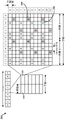
Fig. 3 is a diagram showing an example of a DL frame structure in LTE.
Fig. 4 is a diagram showing an example of a UL frame structure in LTE.
Fig. 5 is a diagram illustrating an example of a radio protocol architecture for the user plane and the control plane.
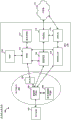
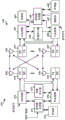
Fig. 6 is a diagram illustrating an example of an evolved node B and user equipment in an access network.
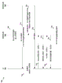
Fig. 7 is a call flow diagram illustrating the data flow between a first base station, a second base station, and a UE in an exemplary embodiment.
Fig. 8 is a flow chart of a first wireless communication method.
Fig. 9 is a flowchart of a second wireless communication method.
Fig. 10 is a flowchart of a third wireless communication method.
Fig. 11 is a data flow diagram illustrating the concept of data flow between different modules/means/components in an exemplary apparatus.
Fig. 12 is a diagram illustrating an example of a hardware implementation for an apparatus employing a processing system.
Detailed Description
The detailed description set forth below in connection with the appended drawings is intended as a description of various configurations and is not intended to represent the only configurations in which the concepts described herein may be practiced. The detailed description includes specific details for the purpose of providing a thorough understanding of the various concepts. It will be apparent, however, to one skilled in the art that these concepts may be practiced without these specific details. In some instances, well-known structures and components are shown in block diagram form in order to avoid obscuring such concepts.
Several aspects of a telecommunications system will now be presented with reference to various apparatus and methods. These apparatus and methods are described in the following detailed description and illustrated in the accompanying drawings by various blocks, modules, components, circuits, steps, processes, algorithms, etc. (collectively referred to as "elements"). These elements may be implemented using electronic hardware, computer software, or any combination thereof. Whether such elements are implemented as hardware or software depends upon the particular application and design constraints imposed on the overall system.
For example, an element or any portion of an element or any combination of elements may be implemented with a "processing system" that includes one or more processors. Examples of processors include microprocessors, microcontrollers, Digital Signal Processors (DSPs), Field Programmable Gate Arrays (FPGAs), Programmable Logic Devices (PLDs), state machines, gated logic, discrete hardware circuits, and other suitable hardware configured to perform the various functions described throughout this disclosure. One or more processors in the processing system may execute software. Software shall be construed broadly to mean instructions, instruction sets, code segments, program code, programs, subprograms, software modules, applications, software packages, routines, subroutines, objects, executables, threads of execution, procedures, functions, etc., whether referred to as software, firmware, middleware, microcode, hardware description language, or other terminology.
Accordingly, in one or more exemplary embodiments, the functions described may be implemented in hardware, software, firmware, or any combination thereof. If implemented in software, the functions may be stored on or encoded on a computer-readable medium as one or more instructions or code. Computer readable media includes computer storage media. A storage media may be any available media that can be accessed by a computer. By way of example, and not limitation, such computer-readable media can comprise Random Access Memory (RAM), Read Only Memory (ROM), electrically erasable programmable ROM (eeprom), compact disk ROM (CD-ROM) or other optical disk storage, magnetic disk storage or other magnetic storage devices, or any other medium that can be used to carry or store desired program code in the form of instructions or data structures and that can be accessed by a computer. Combinations of the above should also be included within the scope of computer-readable media.
Fig. 1 is a diagram illustrating an LTE network architecture 100. The LTE network architecture 100 may be referred to as an Evolved Packet System (EPS) 100. The EPS 100 may include one or more User Equipment (UE)102, evolved UMTS terrestrial radio access network (E-UTRAN)104, evolved packet core network (EPC)110, operator's Internet Protocol (IP) services 122. The EPS may interconnect with other access networks, but those entities/interfaces are not shown for simplicity. As shown, the EPS provides packet switched services, however, those skilled in the art will readily recognize that the various concepts introduced throughout this disclosure may be extended into networks providing circuit switched services.
The E-UTRAN includes evolved node Bs 106 and other eNBs 108 and may include a Multicast Coordination Entity (MCE) 128. The eNB 106 provides user and control plane protocol terminations toward the UE 102. The eNB 106 may connect to other enbs 108 via a backhaul (e.g., an X2 interface). The MCE 128 allocates time/frequency radio resources for an evolved Multimedia Broadcast Multicast Service (MBMS) (eMBMS) and determines a radio configuration (e.g., a Modulation and Coding Scheme (MCS)) for the eMBMS. The MCE 128 may be a separate entity or part of the eNB 106. The eNB 106 may also be referred to as a base station, a node B, an access point, a base transceiver station, a radio base station, a radio transceiver, a transceiver function, a Basic Service Set (BSS), an Extended Service Set (ESS), or some other suitable terminology. eNB 106 provides an access point for UE 102 to EPC 110. Examples of UEs 102 include a cellular phone, a smart phone, a Session Initiation Protocol (SIP) phone, a laptop, a Personal Digital Assistant (PDA), a satellite radio, a global positioning system, a multimedia device, a video device, a digital audio player (e.g., MP3 player), a camera, a game console, a tablet computer, or any other device with similar functionality. UE 102 may also be referred to by those skilled in the art as a mobile station, a subscriber station, a mobile unit, a subscriber unit, a wireless unit, a remote unit, a mobile device, a wireless communications device, a remote device, a mobile subscriber station, an access terminal, a mobile terminal, a wireless terminal, a remote terminal, a handset, a user agent, a mobile client, a client, or some other suitable terminology.
Fig. 2 is a diagram illustrating an example of an access network 200 in an LTE network architecture. In this example, the access network 200 is divided into a plurality of cellular regions (cells) 202. One or more lower power class enbs 208 may have cellular regions 210 that overlap with one or more of cells 202. The lower power class eNB 208 may be a femto cell (e.g., a home eNB (henb)), pico cell, micro cell, or Remote Radio Head (RRH). Macro enbs 204 are each assigned to a respective cell 202 and are configured to provide an access point to EPC 110 for all UEs 206 in cell 202. There is no centralized controller in this example of the access network 200, but a centralized controller may be used in alternative configurations. The eNB 204 is responsible for all radio-related functions including radio bearer control, admission control, mobility control, scheduling, security, and connectivity to the serving gateway 116. An eNB may support one or more (e.g., three) cells (also referred to as sectors). The term "cell" may refer to the smallest coverage area of an eNB and/or eNB subsystem serving a particular coverage area. Further, the terms "eNB", "base station", and "cell" may be used interchangeably herein.
The modulation and multiple access scheme employed by the access network 200 may vary depending on the particular telecommunications standard being deployed. In LTE applications, OFDM is used on the DL and SC-FDMA is used on the UL to support both Frequency Division Duplex (FDD) and Time Division Duplex (TDD). As those skilled in the art will readily recognize from the detailed description that follows, the various concepts presented herein are well suited for LTE applications. However, these concepts can be readily extended to other telecommunications standards employing other modulation and multiple access techniques. By way of example, these concepts may be extended to evolution data optimized (EV-DO) or Ultra Mobile Broadband (UMB). EV-DO and UMB are air interface standards promulgated by the third generation partnership project 2(3GPP2) as part of the CDMA2000 family of standards and employ CDMA to provide broadband internet access to mobile stations. These concepts may also be extended to Universal Terrestrial Radio Access (UTRA) employing wideband-CDMA (W-CDMA) and other variants of CDMA such as TD-SCDMA; global system for mobile communications (GSM) using TDMA; and evolved UTRA (E-UTRA), IEEE 802.11(Wi-Fi), IEEE 802.16(WiMAX), IEEE 802.20, and flash OFDM with OFDMA. UTRA, E-UTRA, UMTS, LTE, and GSM are described in documents from 3GPP organizations. CDMA2000 and UMB are described in documents from the organization of 3GPP 2. The actual wireless communication standard and multiple access technique employed will depend on the particular application and the overall design constraints imposed on the system.
The eNB 204 may have multiple antennas supporting MIMO technology. The use of MIMO technology enables eNB 204 to utilize the spatial domain to support spatial multiplexing, beamforming, and transmit diversity. Spatial multiplexing may be used to transmit different data streams simultaneously on the same frequency. The data stream may be sent to a single UE 206 to increase the data rate or to multiple UEs 206 to increase the overall system capacity. This is achieved by spatially precoding each data stream (i.e., applying a scaling of amplitude and phase) and then transmitting each spatially precoded stream over multiple transmit antennas on the DL. Spatially precoded data streams with different spatial characteristics arrive at the UE 206, which enables each of the UEs 206 to recover one or more data streams destined for that UE 206. On the UL, each UE 206 transmits a spatially precoded data stream, which enables the eNB 204 to identify the source of each spatially precoded data stream.
Spatial multiplexing is typically used when channel conditions are good. Beamforming may be used to focus the transmitted energy in one or more directions when channel conditions are not too good. This may be achieved by spatially precoding data for transmission over multiple antennas. To achieve good coverage at the cell edge, single stream beamforming transmission may be used in conjunction with transmit diversity.
In the detailed description that follows, various aspects of an access network will be described with reference to a MIMO system supporting OFDM on the DL. OFDM is a spread spectrum technique that modulates data over multiple subcarriers within an OFDM symbol. The subcarriers are spaced apart at precise frequencies. The spacing provides "orthogonality" which enables the receiver to recover the data from the subcarriers. In the time domain, a guard interval (e.g., a cyclic prefix) may be added to each OFDM symbol to combat inter-OFDM symbol interference. The UL may use SC-FDMA in the form of DFT-spread OFDM signal to compensate for high peak-to-average power ratio (PAPR).
Fig. 3 is a diagram 300 showing an example of a DL frame structure in LTE. A frame (10 ms) may be divided into 10 equally sized subframes. Each subframe may include two consecutive slots. A resource grid may be used to represent two slots, each slot comprising one resource block. The resource grid is divided into a plurality of resource elements. In LTE, for a conventional cyclic prefix, a resource block contains 12 consecutive subcarriers in the frequency domain and 7 consecutive OFDM symbols in the time domain, for a total of 84 resource elements. For an extended cyclic prefix, a resource block contains 12 consecutive subcarriers in the frequency domain and 6 consecutive OFDM symbols in the time domain, for a total of 72 resource elements. Some of the resource elements indicated as R302, 304 include DL reference signals (DL-RS). The DL-RS includes cell-specific RS (crs) (also sometimes referred to as common RS)302 and UE-specific RS (UE-RS) 304. The UE-RS 304 is transmitted only on resource blocks on which a corresponding Physical DL Shared Channel (PDSCH) is mapped. The number of bits carried by each resource element depends on the modulation scheme. Thus, the more resource blocks a UE receives and the higher the modulation scheme, the higher the data rate for that UE.
Fig. 4 is a diagram 400 illustrating an example of a UL frame structure in LTE. The available resource blocks for the UL may be divided into a data portion and a control portion. The control portion may be formed at both edges of the system bandwidth and may have a configurable size. The resource blocks in the control portion may be allocated to the UE for transmission of control information. The data portion may include all resource blocks not included in the control portion. The UL frame structure is such that contiguous subcarriers are included in the data portion, which may allow all of the contiguous subcarriers in the data portion to be allocated to a single UE.
The resource blocks 410a, 410b in the control portion may be allocated to the UE to transmit control information to the eNB. The resource blocks 420a, 420b in the data portion may also be allocated to the UE to transmit data to the eNB. The UE may send control information in a Physical UL Control Channel (PUCCH) on the allocated resource blocks in the control portion. The UE may transmit only data or both data and control information in a Physical UL Shared Channel (PUSCH) on the allocated resource blocks in the data portion. The UL transmission may span both slots of a subframe and may hop across frequency.
The initial system access may be performed using a set of resource blocks and UL synchronization may be achieved in a Physical Random Access Channel (PRACH) 430. The PRACH 430 carries a random sequence and cannot carry any UL data/signaling. Each random access preamble occupies a bandwidth corresponding to 6 consecutive resource blocks. The starting frequency is specified by the network. That is, the transmission of the random access preamble is limited to certain time and frequency resources. There is no frequency hopping for PRACH. The PRACH attempt is carried in a sequence of a single subframe (1 ms) or a few consecutive subframes, and the UE is only able to make a single PRACH attempt per frame (10 ms).
Fig. 5 is a diagram 500 illustrating an example of a radio protocol architecture for the user and control planes in LTE. The radio protocol architecture for the UE and eNB is shown with three layers: layer 1, layer 2, and layer 3. Layer 1(L1 layer) is the lowest layer and implements various physical layer signal processing functions. The L1 layer will be referred to herein as the physical layer 506. Layer 2(L2 layer) 508 is located above the physical layer 506 and is responsible for the link between the UE and the eNB on the physical layer 506.
In the user plane, the L2 layer 508 includes: a Medium Access Control (MAC) sublayer 510, a Radio Link Control (RLC) sublayer 512, and a Packet Data Convergence Protocol (PDCP)514 sublayer, which terminate at the eNB on the network side. Although not shown, the UE may have several upper layers above the L2 layer 508, including a network layer (e.g., IP layer) that terminates at the PDN gateway 118 on the network side, and an application layer that terminates at the other end of the connection (e.g., far end UE, server, etc.).
The PDCP sublayer 514 provides multiplexing between different radio bearers and logical channels. The PDCP sublayer 504 also provides header compression for upper layer data packets to reduce radio transmission overhead, security by ciphering the data packets, and handover support for UEs between enbs. The RLC sublayer 512 provides segmentation and reassembly of upper layer data packets, retransmission of lost data packets, and reordering of data packets to compensate for out-of-order reception caused by hybrid automatic repeat request (HARQ). The MAC sublayer 510 provides multiplexing between logical channels and transport channels. The MAC sublayer 510 is also responsible for allocating various radio resources (e.g., resource blocks) among UEs in one cell. The MAC sublayer 510 is also responsible for HARQ operations.
In the control plane, the radio protocol architecture for the UE and eNB is essentially the same for the physical layer 506 and the L2 layer 508, except that there is no header compression function for the control plane. The control plane also includes a Radio Resource Control (RRC) sublayer 516 in layer 3 (layer L3). The RRC sublayer is responsible for obtaining radio resources (e.g., radio bearers) and configuring the lower layers using RRC signaling between the eNB and the UE.
Fig. 6 is a block diagram of an eNB 610 in communication with a UE 650 in an access network. In the DL, upper layer packets from the core network are provided to a controller/processor 675. The controller/processor 675 implements the functionality of the L2 layer. In the DL, the controller/processor 675 provides header compression, ciphering, packet segmentation and reordering, multiplexing between logical and transport channels, and radio resource allocation to the UE 650 based on various priority metrics. The controller/processor 675 is also responsible for HARQ operations, retransmission of lost packets, and signaling to the UE 650.
A Transmit (TX) processor 616 performs various signal processing functions for the L1 layer (i.e., the physical layer). The signal processing functions include coding and interleaving to facilitate Forward Error Correction (FEC) at the UE 650, and mapping to signal constellations based on various modulation schemes (e.g., binary phase-shift keying (BPSK), quadrature phase-shift keying (QPSK), M-phase-shift keying (M-PSK), M-quadrature amplitude modulation (M-QAM)). The coded and modulated symbols are then split into parallel streams. Each stream is then mapped to OFDM subcarriers, multiplexed with reference signals (e.g., pilots) in the time and/or frequency domain, and then combined together using an Inverse Fast Fourier Transform (IFFT) to produce a physical channel carrying a time domain OFDM symbol stream. The OFDM streams are spatially precoded to produce a plurality of spatial streams. The channel estimates from channel estimator 674 may be used to determine coding and modulation schemes, as well as for spatial processing. The channel estimate may be derived from a reference signal and/or channel condition feedback transmitted by the UE 650. Each spatial stream may then be provided to a different antenna 620 via a separate transmitter 618 TX. Each transmitter 618TX may modulate an RF carrier with a corresponding spatial stream for transmission.
At the UE 650, each receiver 654RX receives a signal through its respective antenna 652. Each receiver 654RX recovers information modulated on an RF carrier and provides the information to a Receive (RX) processor 656. The RX processor 656 performs various signal processing functions at the L1 layer. The RX processor 656 may perform spatial processing on the information to recover any spatial streams destined for the UE 650. If multiple spatial streams are intended for the UE 650, they may be combined into a single OFDM symbol stream by an RX processor 656. The RX processor 656 then converts the OFDM symbol stream from the time-domain to the frequency domain using a Fast Fourier Transform (FFT). The frequency domain signal includes a separate OFDM symbol stream for each subcarrier in the OFDM signal. The symbols on each subcarrier and the reference signal are recovered and demodulated by determining the most likely signal constellation points transmitted by the eNB 610. These soft decisions may be based on channel estimates computed by the channel estimator 658. The soft decisions are then decoded and deinterleaved to recover the data and control signals that were originally transmitted by the eNB 610 on the physical channel. The data and control signals are then provided to the controller/processor 659.
The controller/processor 659 implements the L2 layer. The controller/processor can be associated with a memory 660 that stores program codes and data. The memory 660 may also be referred to as a computer-readable medium. In the UL, the controller/processor 659 provides demultiplexing between transport and logical channels, packet reassembly, deciphering, header decompression, control signal processing to recover upper layer packets from the core network. The upper layer packets are then provided to a data sink 662, which data sink 662 represents all protocol layers above the L2 layer. Various control signals may also be provided to a data sink 662 for processing by L3. The controller/processor 659 is also responsible for error detection using Acknowledgement (ACK) and/or Negative Acknowledgement (NACK) protocols to support HARQ operations.
In the UL, a data source 667 is used to provide upper layer packets to the controller/processor 659. The data source 667 represents all protocol layers above the L2 layer. Similar to the functionality described in connection with the DL transmission by the eNB 610, the controller/processor 659 implements the L2 layer for the user plane and the control plane by providing header compression, ciphering, packet segmentation and reordering, and multiplexing between logical and transport channels based on radio resource allocations by the eNB 610. The controller/processor 659 is also responsible for HARQ operations, retransmission of lost packets, and signaling to the eNB 610.
The channel estimates derived by channel estimator 658 from the reference signals or feedback transmitted by eNB 610 may be used by TX processor 668 to select the appropriate coding and modulation schemes, and to facilitate spatial processing. The spatial streams generated by the TX processor 668 may be provided to different antennas 652 via separate transmitters 654 TX. Each transmitter 654TX may modulate an RF carrier with a corresponding spatial stream for transmission.
UL transmissions are processed at the eNB 610 in a manner similar to that described in connection with the receiver function at the UE 650. Each receiver 618RX receives a signal through its respective antenna 620. Each receiver 618RX recovers information modulated on an RF carrier and provides the information to an RX processor 670. RX processor 670 may implement the L1 layer.
The controller/processor 675 implements the L2 layer. The controller/processor 675 can be associated with a memory 676 that stores program codes and data. The memory 676 may also be referred to as a computer-readable medium. In the UL, the controller/processor 675 provides demultiplexing between transport and logical channels, packet reassembly, deciphering, header decompression, control signal processing to recover upper layer packets from the UE 650. Upper layer packets from the controller/processor 675 may be provided to the core network. The controller/processor 675 is also responsible for error detection using ACK and/or NACK protocols to support HARQ operations.
The cells may be dormant or may transition to a dormant state (mode) to conserve power, to reduce interference to neighboring cells and/or UEs served by neighboring cells, and/or to reduce handovers received for high mobility UEs that are likely to experience Radio Link Failure (RLF) with the cell. A dormant cell may be referred to as a dormant eNB, a New Carrier Type (NCT) dormant eNB, or a NCT dormant cell. For a UE in an RRC connected state, the UE measurement report may need to contain a global cell Identifier (ID). A UE in an RRC idle state (e.g., an RRC idle UE) may need to be able to access a dormant cell after receiving a page from an active cell on which the UE is camped.
Fig. 7 is a call flow diagram 700 illustrating an exemplary access procedure by a UE701 for a dormant eNB702, the UE701 communicating with an active cell 703 and camped on the active cell 703. The dormant eNB702 transmits sparse overhead signals on an overhead channel. The overhead signals include Primary Synchronization Signals (PSS), Secondary Synchronization Signals (SSS), location reference signals (PRS), Channel State Information (CSI) Reference Signals (RS) (CSI-RS), CRS, a Master Information Block (MIB), and System Information Blocks (SIB). The dormant eNB702 transmits overhead signals on a small subset of subframes within each radio frame or within each of a plurality of radio frames. The sparse transmission of overhead signals contains enough information to allow a UE701 in an RRC connected state with an active eNB703 (also referred to as a serving eNB) to detect and measure a dormant eNB 702. The access procedure in diagram 700 applies to RRC-idle UEs that cannot camp on the dormant eNB 702.
Dormant eNB702 sends overhead channel transmissions in bursts. The bursts are performed at a reduced frequency (periodicity). The dormant eNB702 may transmit PSS, SSS, PRS, CSI-RS, CRS, MIB, and SI in a System Information (SI) block (SIB) in N millisecond bursts with an L millisecond offset every M milliseconds. N, M may be configured by the active eNB703 as well as the value of L. The active eNB703 may configure N, M and the value of L through broadcast in the SI and/or through unicast RRC signaling. The active eNB may signal the UE701 to look at multiple burst configurations to obtain overhead signals from the dormant eNB 702. The System Frame Number (SFN) may be synchronized with neighboring cells through, for example, over-the-air (OTA) synchronization, backhaul-based synchronization, etc. Alternatively, the dormant eNB702 may have an SFN/subframe offset from a neighboring cell.
The dormant eNB702 may sparsely transmit the MIB and SIBs. The dormant eNB702 may transmit only a subset of the information that the eNB702 normally transmits when the eNB702 is active or in an active state. For example, the dormant eNB702 may send a reduced version of SIB 1(SIB1) that includes only a subset of the information normally included in SIB 1. Transmitting SI sparsely (e.g., with less frequency) reduces coverage for discovery of dormant enbs 702.
The system bandwidth of the dormant eNB702 may be the same as the system bandwidth of the active eNB 703. If the system bandwidth of the dormant eNB702 is different, the system bandwidth of the dormant eNB702 may be communicated in the MIB. The SFN/subframe offset of dormant eNB702 may be the same as the SFN/subframe offset of active eNB 703. If the SFN/subframe offset for the dormant eNB702 is different, the active eNB703 may signal the difference to the UE 701. A dormant eNB702 overhead channel transmission may include an indication that the eNB702 is dormant or in a dormant state. The indication may be sent in MIB, SI (e.g., SIB1), or a reduced version of SIB 1. This indication allows the UE701 to determine on what subframes the UE701 may detect the dormant eNB 702.
To get the UE701 access to the dormant eNB702, the dormant eNB702 sends the UE701 information that the UE701 can use to access the dormant eNB 702. When the eNB702 is in the dormant state, the dormant eNB702 is configured to transmit overhead signals with a reduced frequency at 720. At 722, the UE701 obtains parameters for the overhead channel of the dormant eNB702 from the active eNB703 while continuing to monitor the paging channel from the active eNB 703. The parameters indicate the resources (e.g., subframes, frequencies) over which overhead signals may be obtained from the dormant eNB 702. On the indicated resources, the UE701 receives PSS and SSS and detects a dormant eNB702 based on the received PSS and SSS. On the indicated resources, the UE701 also receives a CRS and a cell identifier associated with the dormant eNB 702. The cell identifier may be a global cell identifier or an extended cell identifier. The UE701 determines a Reference Signal Received Quality (RSRQ), a Reference Signal Received Power (RSRP), or a signal to interference plus noise ratio (SINR) of the CRS received at a burst location (e.g., 10 milliseconds every 200 milliseconds).
The RRC-idle UE performs measurements of the neighbor cells at the burst location. For example, a sleeping cell may transmit overhead signals on an overhead channel every 10 milliseconds of 200 milliseconds. An RRC-idle UE performs cell selection and reselection procedures only on active cells. The UE701 in the RRC idle state may read the transmitted MIB/SI or SIB1 reduced version information on the dormant cell to enable direct access to the dormant cell if the UE701 is in coverage of the dormant cell 702. While idle UEs 701 may obtain RACH and PRACH configurations to directly access the dormant eNB702, idle UEs 701 continue to camp on the active eNB 703. An idle UE701 may perform immediate reselection and access to a dormant eNB702 in response to a paging notification from an active eNB 703. In an alternative, an idle UE701 may initiate cell reselection on its own before receiving a paging notification from an active eNB 703.
At 724, the active eNB703 may communicate with the dormant eNB702 to configure subframes used by the dormant eNB702 for data transmissions and overhead channels when activated. At 726, SI may be obtained from the dormant eNB702 while the UE701 is camped on the active eNB 703. The SI may indicate a random access configuration for performing a random access procedure or a part of a random access procedure. The information may be an explicit indication of the random access configuration or may be an implicit indication of the random access configuration. For example, the SI may include a cell identifier, and the UE701 may implicitly determine the random access configuration based on the cell identifier. At 728, upon receiving a paging notification from the active eNB703, the UE701 may determine to reselect from the active eNB703 to the dormant eNB 702. The UE701 may make a decision to reselect based on the determined RSRP, RSRQ, and/or SINR of the received CRS or other reference signals.
At 726, the UE701 may obtain limited SI from the dormant eNB702 before the UE701 initiates a random access procedure with the dormant eNB 702. The limited SI may be in a reduced version of SIB1 and may provide sufficient information to the UE701 for the UE701 to start the random access procedure by sending a PRACH signature sequence to the dormant eNB 702. The UE701 may need to obtain more information (e.g., from the active eNB 703) to complete the random access procedure. The random access procedure may be modified to transmit the remaining SI to the UE701 during the random access procedure.
The random access procedure between idle UE701 and dormant eNB702 includes several messages, including message 1, random access preamble; message 2, random access response; message 3, L2/L3 message; message 4, RRC connection reconfiguration message. The UE701 initiates access by sending message 1. Message 1 is a PRACH preamble signature sequence. At 703, after receiving message 1 from the UE701, the dormant eNB702 may send a request for activation to the active eNB703 before sending message 2 (random access response). In another example, the dormant eNB702 may send a request for activation to the overlapping macro cell before sending message 2 (random access response). At 732, the dormant eNB702 responds to the received message 1 with message 2 (random access response). Message 2 (random access response) may include additional SI and/or other necessary common parameters for transmission of message 3(L2/L3 message). The UE701 prepares an L2/L3 message based on the additional SI and/or other common parameters, and sends an L2/L3 message to the dormant eNB702 at 734.
At 736, the dormant eNB702 responds with message 4(RRC connection reconfiguration message). The dormant eNB702 then transitions to an active mode and transmits an overhead signal with the nominal frequency at 738. The eNB702 in the active state transmits overhead signals with a greater frequency than when in the dormant state. After transitioning to the active state, the eNB702 may indicate in the SI that the eNB702 is in the active state rather than the dormant state. In particular, when in the active state, the eNB may transmit a MIB including the active state indication, system bandwidth, and other information such as downlink control channel configuration, SIB1 allocation, and the like. The active state indication may include a number of bits to indicate different configurations (e.g., from a frequency and/or bandwidth aspect) of the PSS, SSS, and reference signals such as PRS, CSI-RS, CRS, or other reference signals. The nominal frequency may be less than the frequency used by the active eNB703 to transmit overhead signals. Transmitting overhead signals at a smaller frequency than the active eNB703 may be useful in order to limit interference to UEs served by the active eNB703 and may be useful to reduce handover rates for high mobility UEs that have not yet been handed over to the eNB 702. At the eNB702, a high mobility UE may have a greater likelihood of RLF. Thus, when the eNB702 transitions from the dormant state to the active state, data transmission is restricted, at least initially, to a configured subset of subframes in order to avoid creating conditions that may lead to RLF for nearby UEs. Radio Resource Management (RRM) and Radio Link Management (RLM) on the active eNB703 may also be restricted to a set of subframes or resources when the eNB702 is not transmitting signals.
There are a number of options for the dormant eNB702 to provide sufficient information to an idle UE701 to allow the UE701 to begin the process of reselecting to the dormant eNB 702. Options include communicating information through SIB1 reductions or using global or enhanced cell IDs to implicitly derive information. When using implicit derivation, the active eNB703 may configure a mapping between the cell ID of the dormant eNB702 and the PRACH configuration to be used with that eNB. The dormant eNB702 may include a cell ID in overhead data transmitted by the dormant eNB 702. The active eNB may send mapping information to the UE 701.
A reduced version of SIB1 may include only a subset of the information typically included in SIB 1. The reduced version of SIB1 may include information related to cell access as well as cell selection information. The reduced version of SIB1 may also include RACH configuration information. A reduced version of SIB1 may include only a subset of the RACH configuration information needed to perform the random access procedure. In particular, a reduced version of SIB1 may include only the information needed to send message 1 (random access preamble). When SIB-1 reduction is utilized, RACH configuration information may be transmitted explicitly or implicitly. As discussed above, for implicit transmissions, the cell identity of the dormant eNB702 may be linked to a particular RACH configuration. As discussed above, for explicit transmissions, a full RACH configuration may be transmitted or a subset of the RACH configuration may be transmitted.
For example, a reduced version of SIB1 that includes a subset of the information may have the following example configuration. The UE701 in the RRC idle state may assume the following configuration of the dormant eNB702 on the same carrier frequency as the active eNB703 with respect to the contents of the SIB 1.
-cellAccess relatedInfo (information related to cell Access)
Plmn-identylist ═ identical to active cells
Trackingarea code is the same as the active cell
cellIdentity included in SIB1 reduced edition
cellBarred ═ notgarred (not prohibited)
intraFreqReselection ═ Admission
csg-Indication error
Csg Identity is not included in SIB1 reduced edition
-cellSelectionInfo (cell selection information)
q-RxLevMin ═ included in a reduced version of SIB1
q-RxLevMinOffset included in a reduced version of SIB1
-p-Max not comprising or being the same as an active cell
-freqBandIndicator is the same as active cell
-schedulinglnfolist ═ not included in SIB1 reduced version
-tdd-Config ═ does not include or is the same as an active cell
si-WindowLength not included in the reduced version of SIB1
Systemlnfovaluetag is not included in the reduced version of SIB1
-noncritical extension not included in SIB1 reduced edition
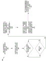
Fig. 8 is a flow chart 800 of a method of wireless communication. The method may be performed by a UE, such as UE 701. At 802, a UE receives an indication of resources for detecting a first base station (e.g., a dormant eNB) from a second base station (e.g., an active eNB). For example, referring back to fig. 7, at 722, the UE701 obtains parameters for an overhead channel of the dormant eNB702 from the active eNB 703. As discussed above, the parameters indicate resources (e.g., subframes, frequencies) over which overhead signals may be obtained from the dormant eNB 702. At 804, the UE receives a synchronization signal and an information block from a first base station. The information block comprises an indication of a random access configuration for performing at least part of a random access procedure. For example, referring back to fig. 7, at 726, when the UE701 camps on the active eNB703, the UE701 may obtain SI from the dormant eNB 702. As discussed above, the SI may indicate a random access configuration for performing a random access procedure or a portion of a random access procedure.
At 806, the UE determines whether a paging notification should be received from the second base station. If the paging notification is received, the UE determines whether to reselect to the first base station at step 808. For example, referring back to fig. 7, at 728, upon receiving a paging notification from the active eNB703, the UE701 may determine to reselect from the active eNB703 to the dormant eNB 702. If the UE determines not to reselect, the UE remains at the second base station. If the UE determines to reselect, then at 810, the UE performs at least a portion of a random access procedure with the first base station to reselect from the second base station to the first base station based on the indicated random access configuration. At 812, the UE receives system information during the random access procedure in a random access response from the first base station, the system information indicating a second random access configuration for performing a remaining portion of the random access procedure. For example, referring back to fig. 7, during the random access procedure of an idle UE701 and a dormant eNB702, after receiving message 1 from the UE701 at 703, the dormant eNB702 may send a request for activation to the active eNB703 before sending message 2 (random access response). For example, as discussed above, the dormant eNB702 responds to the received message 1 with message 2 (random access response) at 732. For example, as discussed above, message 2 (random access response) may include additional SI and/or other necessary common parameters for transmission of message 3(L2/L3 message).
At 814, the UE sends an L2/L3 message to the first base station based on the system information received in the received random access response. For example, as discussed above, the UE prepares an L2/L3 message based on the additional SI and/or other common parameters and sends an L2/L3 message to the dormant eNB702 at 734.
The information block received by the UE may include a cell identifier of the first base station. The indication of the random access configuration may be a cell identifier. In such a configuration, the UE determines a random access configuration based on the cell identifier. For example, as discussed above, the SI obtained from the dormant eNB702 may include a cell identifier, and the UE701 may implicitly determine the random access configuration based on the cell identifier. The information blocks may be MIB or SIB. The information block may be SIB 1. The information block may comprise a subset of SIB1 and thus may be a reduced version of SIB 1. For example, as discussed above, the overhead signals transmitted from the dormant eNB702 over the overhead channel may include MIB, SIB1, or a reduced version of SIB 1.
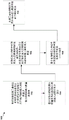
Fig. 9 is a flow chart 900 illustrating a method of wireless communication. The method may be performed by a first base station (e.g., a dormant eNB). At 902, a first base station transmits an information block to a UE while the UE is camped on a second base station. The information block comprises an indication of a random access configuration for performing at least part of a random access procedure. For example, referring back to fig. 7, at 726, when the UE701 camps on the active eNB703, the UE701 may obtain SI from the dormant eNB 702. As discussed above, the SI may indicate a random access configuration for performing a random access procedure or a portion of a random access procedure.
At 904, the first base station performs at least a portion of a random access procedure with the UE based on the indicated random access configuration. At 906, the first base station transmits system information to the UE during a random access procedure in a random access response. The system information indicates a second random access configuration for performing a remaining part of the random access procedure. At 908, the first base station receives an L2/L3 message from the UE based on the system information sent in the random access response. For example, referring back to fig. 7, during a random access procedure between an idle UE701 and a dormant eNB702, after receiving message 1 from the UE701 at 703, the dormant eNB702 may send a request for activation to the active eNB703 before sending message 2 (random access response). For example, as discussed above, the dormant eNB702 responds to the received message 1 with message 2 (random access response) at 732. For example, as discussed above, message 2 (random access response) may include additional SI and/or other necessary common parameters for transmission of message 3(L2/L3 message). For example, as discussed above, the UE701 prepares an L2/L3 message based on the additional SI and/or other common parameters, and sends an L2/L3 message to the dormant eNB702 at 734. At 910, the first base station may receive a configuration of subframes for data transmission with the UE from the second base station. For example, referring back to fig. 7, at 736 the dormant eNB702 responds with message 4(RRC connection configuration message). For example, as discussed above, the dormant eNB702 then transitions to an active mode and transmits overhead signals with the nominal frequency at 738.
The information block transmitted by the first base station may include a cell identifier of the first base station. The indication of the random access configuration may be indicated by a cell identifier. In such a configuration, the UE determines a random access configuration based on the cell identifier. For example, as discussed above, the SI obtained from the dormant eNB702 may include a cell identifier, and the UE701 may implicitly determine the random access configuration based on the cell identifier. The information blocks may be MIB or SIB. The information block may be SIB 1. The information block may comprise a subset of SIB1 and thus may be a reduced version of SIB 1. For example, as discussed above, the overhead signals transmitted from the dormant eNB702 over the overhead channel may include MIB, SIB1, or a reduced version of SIB 1.
Fig. 10 is a flow chart 1000 of a method of wireless communication. The method may be performed by a UE, such as UE 701. At 1002, a UE receives a SIB from a base station. The SIB includes a subset of the information included in SIB 1. The SIB includes information related to cell access as well as cell selection information. At 1004, the UE performs at least a portion of a random access procedure with the base station based on the received SIB. For example, referring back to fig. 7, before the UE701 initiates a random access procedure with the dormant eNB702, the UE701 may obtain limited SI from the dormant eNB702 at 726. For example, as discussed above, the limited SI may be in a reduced version of SIB1 and may provide sufficient information to the UE701 for the UE701 to start a random access procedure by transmitting a PRACH signature sequence to the dormant eNB 702. For example, as discussed above, a reduced version of SIB1 may include only a subset of the information typically included in SIB1, and may include information related to cell access as well as cell selection information.
At 1006, the UE receives the SIB from the base station when the base station is in the dormant state, and after performing the random access procedure, receives a second SIB from the base station when the base station is in the active state. The SIB includes a subset of the information included in the second SIB. The UE may receive the first SIB with a first frequency and may receive the second SIB with a second frequency that is greater than the first frequency. For example, as discussed above, the UE701 may need to obtain more information from the active eNB703 to complete the random access procedure. For example, as discussed above, the random access procedure may be modified to transmit the remaining SI to the UE701 during the random access procedure.
Fig. 11 is a data flow diagram illustrating the concept of data flow between different modules/means/components in an exemplary apparatus 1102. The apparatus may be a UE. The apparatus includes a receiving module 1104, a transmitting module 1106, a reselection determination module 1108, and a random access procedure module 1110.
While resident on the second base station 1150, the receiving module 1104 receives the information block from the first base station 1130 via 1172. In an aspect, the information block includes an indication of a random access configuration for performing at least a portion of a random access procedure. The reselection determination module 1108 determines to reselect from the second base station 1150 to the first base station 1130. The reselection determination module 1108 may indicate to the random access procedure module 1110 the determination to reselect to the first base station 1130 via 1174. The random access procedure module 1110, via the receiving module 1104 at 1172 and 1176 and via the transmitting module 1106 at 1178 and 1180, performs at least a portion of a random access procedure with the first base station 1130 based on the indicated random access configuration to reselect from the second base station 1150 to the first base station 1130.
In an aspect, the receiving module 1104 may receive an indication of resources for detecting the first base station 1130 from the second base station 1150 at 1182. In such an aspect, the information block is received in the indicated resource. In an aspect, the reselection determination module 1108 may receive paging notifications from the second base station via the receiving module 1104 at 1182 and 1184. In such an aspect, the determination to reselect is based on the received paging notification.
In an aspect, the information block may include a cell identifier of the first base station 1130, and the indication of the random access configuration is the cell identifier. In such an aspect, the random access procedure module 1110 may determine the random access configuration based on the cell identifier. In an aspect, the information block is a MIB. In an aspect, the information blocks are SIBs. In such an aspect, the information block may be a SIB 1. In such an aspect, the information block may be a subset of the SIB 1.
In an aspect, the random access procedure module 1110 may receive system information via the receiving module 1104 during a random access procedure at 1172 and 1176. In an aspect, system information may be received from the first base station 1130 in the random access response, the system information indicating a second random access configuration for performing a remaining portion of the random access procedure. In an aspect, the random access procedure module 1110 may transmit an L2/L3 message to the first base station 1130 via the transmission module 1106 at 1178 and 1180 based on the system information received in the received random access response.
The apparatus may include additional modules that perform each of the steps of the algorithm in the flow chart of fig. 8 described above. As such, each of the steps in the flow chart of FIG. 8 above may be performed by a module, and the apparatus may include one or more of those modules. A module may be one or more hardware components specifically configured to perform the process/algorithm, implemented by a processor configured to perform the process/algorithm, stored within a computer-readable medium for implementation by a processor, or some combination thereof.
Fig. 12 is a diagram 1200 illustrating an example of a hardware implementation for an apparatus 1102' employing a processing system 1214. The processing system 1214 may be implemented with a bus architecture, represented generally by the bus 1224. The bus 1224 may include any number of interconnected buses and bridges depending on the specific application of the processing system 1214 and the overall design constraints. The bus 1224 links together various circuits including one or more processors and/or hardware modules (represented by the processor 1204, the modules 1104, 1106, 1108, 1110, and the computer-readable medium/memory 1206). The bus 1224 may also link various other circuits such as timing sources, peripherals, voltage regulators, and power management circuits, which are well known in the art, and therefore, will not be described any further.
The processing system 1214 may be coupled to a transceiver 1210. The transceiver 1210 is coupled to one or more antennas 1220. The transceiver 1210 provides a means for communicating with various other apparatus over a transmission medium. The transceiver 1210 receives a signal from the one or more antennas 1220, extracts information from the received signal, and provides the extracted information to the processing system 1214, and in particular the receive module 1104. In addition, the transceiver 1210 receives information from the processing system 1214 (and in particular the transmitting module 1106) and generates a signal to be applied to the one or more antennas 1220 based on the received information. The processing system 1214 includes a processor 1204 coupled to a computer-readable medium/memory 1206. The processor 1204 is responsible for general processing, including the execution of software stored on the computer-readable medium/memory 1206. The software, when executed by the processor 1204, causes the processor system 1214 to perform the various functions described supra for any particular apparatus. The computer-readable medium/memory 1206 may also be used for storing data that is manipulated by the processor 1204 when executing software. The processing system also includes at least one of the modules 1104, 1106, 1108, 1110. The modules may be software modules running in the processor 1204, resident/stored on the computer readable medium/memory 1206, one or more hardware modules coupled to the processor 1204, or some combination thereof. The processor system 1214 may be a component of the UE 650 and may include the memory 660 and/or at least one of the TX processor 668, the RX processor 656, and the controller/processor 659.
In one configuration, the means for wireless communicating 1102/1102' includes means for receiving an information block from a first base station while it is camped on a second base station, the information block including an indication of a random access configuration for performing at least a portion of a random access procedure, means for determining to reselect from the second base station to the first base station, and means for performing at least a portion of the random access procedure with the first base station based on the indicated random access configuration to reselect to the first base station with the second base station. The apparatus 1102/1102' may also include means for receiving, from the second base station, an indication of resources for detecting the first base station, wherein the information block is received in the indicated resources. The apparatus 1102/1102' may also include means for receiving a paging notification from the second base station, wherein the determination to reselect is based on the received paging notification. In an aspect, the information block may include a cell identifier of the first base station, the indication of the random access configuration is the cell identifier, and the apparatus 1102/1102' may further include means for determining the random access configuration based on the cell identifier. The apparatus 1102/1102' may also include means for receiving system information during a random access procedure. In an aspect, system information may be received from the first base station in a random access response, the system information indicating a second random access configuration for performing a remaining portion of the random access procedure. In such an aspect, the apparatus 1102/1102' may also include means for transmitting an L2/L3 message to the first base station based on the system information received in the received random access response.
The aforementioned means may be one or more of the aforementioned modules of the apparatus 1102 and/or the processing system 1214 of the apparatus 1102' configured to perform the recited functions by the aforementioned means. As described supra, the processing system 1214 may include the TX processor 668, the RX processor 656, and the controller/processor 659. As such, in one configuration, the means may be the TX processor 668, the RX processor 656, and the controller/processor 659 configured to perform the functions recited by the means.
It should be understood that the specific order or hierarchy of steps in the processes/flow diagrams disclosed is merely illustrative of exemplary approaches. It should be understood that the specific order or hierarchy of steps in the processes/flow diagrams may be rearranged based on design preferences. In addition, some steps may be combined or omitted. The accompanying method claims present elements of the various steps in a sample order, and are not meant to be limited to the specific order or hierarchy presented.
The previous description is provided to enable any person skilled in the art to practice the various aspects described herein. Various modifications to these aspects will be readily apparent to those skilled in the art, and the generic principles defined herein may be applied to other aspects. Thus, the claims are not intended to be limited to the aspects shown herein, but is to be accorded the full scope consistent with the language claims, wherein reference to an element in the singular is not intended to mean "one and only one" unless specifically so stated, but rather "one or more. The word "exemplary" is used herein to mean serving as an example, instance, or illustration. Any aspect described herein as "exemplary" is not necessarily to be construed as preferred or advantageous over other aspects. The term "some" means one or more unless explicitly stated otherwise. Combinations such as "A, B or at least one of C", "A, B, and at least one of C", and "A, B, C or any combination thereof" include any combination of A, B and/or C, and may include multiples of a, multiples of B, or multiples of C. Specifically, a combination such as "at least one of A, B or C", "at least one of A, B and C", and "A, B, C or any combination thereof" may be a only, B only, C, A and B, A and C, B and C only, or a and B and C, wherein any such combination may contain one or more members or several members of A, B or C. All structural and functional equivalents to the elements of the various aspects described throughout this disclosure that are known or later come to be known to those of ordinary skill in the art are expressly incorporated herein by reference and are intended to be encompassed by the claims. Moreover, nothing disclosed herein is intended to be dedicated to the public regardless of whether such disclosure is explicitly recited in the claims. No claim element is to be construed as a functional module unless the element is explicitly recited using the phrase "unit for … …".
Claims (24)
1. A method of wireless communication by a first base station, comprising:
transmitting an information block to a user equipment, UE, while camped on a second base station, the information block comprising an indication of a random access configuration for performing at least a part of a random access procedure;
performing at least a portion of a random access procedure with the UE based on the indicated random access configuration; and
transmitting system information to the UE in a random access response during the random access procedure, the system information indicating a second random access configuration for performing a remaining portion of the random access procedure.
2. The method of claim 1, wherein the information block comprises a cell identifier, the random access procedure being indicated by the cell identifier.
3. The method of claim 1, wherein the information block is a Master Information Block (MIB).
4. The method of claim 1, wherein the information block is a system information block, SIB.
5. The method of claim 4, wherein the information block is SIB 1(SIB 1).
6. The method of claim 4, wherein the information block is a subset of SIB 1(SIB 1).
7. The method of claim 1, further comprising: receiving a layer 2 (L2)/layer 3(L3) (L2/L3) message from the UE based on the system information sent in the random access response.
8. The method of claim 1, further comprising: receiving, from a second base station, a subframe configuration for use in data transmission with the UE.
9. An apparatus for wireless communication, the apparatus being a first base station, the apparatus comprising:
means for transmitting an information block to a user equipment, UE, when camped on a second base station, the information block comprising an indication of a random access configuration for performing at least a part of a random access procedure;
means for performing at least a portion of a random access procedure with the UE based on the indicated random access configuration; and
means for transmitting system information to the UE in a random access response during the random access procedure, the system information indicating a second random access configuration for performing a remaining portion of the random access procedure.
10. The apparatus of claim 9, wherein the information block comprises a cell identifier, the random access procedure being indicated by the cell identifier.
11. The apparatus of claim 9, wherein the information block is a Master Information Block (MIB).
12. The apparatus of claim 9, wherein the information block is a system information block, SIB.
13. The apparatus of claim 12, wherein the information block is SIB 1(SIB 1).
14. The apparatus of claim 12, wherein the information block is a subset of SIB 1(SIB 1).
15. The apparatus of claim 9, further comprising: means for receiving a layer 2 (L2)/layer 3(L3) (L2/L3) message from the UE based on the system information sent in the random access response.
16. The apparatus of claim 9, further comprising: means for receiving, from a second base station, a subframe configuration for use in data transmission with the UE.
17. An apparatus for wireless communication, the apparatus being a first base station, the apparatus comprising:
a memory; and
at least one processor coupled to the memory and configured to:
transmitting an information block to a user equipment, UE, while camped on a second base station, the information block comprising an indication of a random access configuration for performing at least a part of a random access procedure;
performing at least a portion of a random access procedure with the UE based on the indicated random access configuration; and
transmitting system information to the UE in a random access response during the random access procedure, the system information indicating a second random access configuration for performing a remaining portion of the random access procedure.
18. The apparatus of claim 17, wherein the information block comprises a cell identifier, the random access procedure being indicated by the cell identifier.
19. The apparatus of claim 17, wherein the information block is a Master Information Block (MIB).
20. The apparatus of claim 17, wherein the information block is a system information block, SIB.
21. The apparatus of claim 20, wherein the information block is SIB 1(SIB1) or a subset of SIB 1(SIB 1).
22. The apparatus of claim 17, wherein the at least one processor is further configured to: receiving a layer 2 (L2)/layer 3(L3) (L2/L3) message from the UE based on the system information sent in the random access response.
23. The apparatus of claim 17, wherein the at least one processor is further configured to: receiving, from a second base station, a subframe configuration for use in data transmission with the UE.
24. A non-transitory computer-readable medium for a first base station and storing computer executable code for wireless communication, comprising code to:
transmitting an information block to a user equipment, UE, while camped on a second base station, the information block comprising an indication of a random access configuration for performing at least a part of a random access procedure;
performing at least a portion of a random access procedure with the UE based on the indicated random access configuration; and
transmitting system information to the UE in a random access response during the random access procedure, the system information indicating a second random access configuration for performing a remaining portion of the random access procedure.
Applications Claiming Priority (5)
| Application Number | Priority Date | Filing Date | Title |
|---|---|---|---|
| US201361767218P | 2013-02-20 | 2013-02-20 | |
| US61/767,218 | 2013-02-20 | ||
| US14/181,580 | 2014-02-14 | ||
| US14/181,580 US9014143B2 (en) | 2013-02-20 | 2014-02-14 | Methods and apparatus for accessing dormant cells |
| CN201480009245.9A CN105075347B (en) | 2013-02-20 | 2014-02-19 | Method and apparatus for the cell for accessing suspend mode |
Related Parent Applications (1)
| Application Number | Title | Priority Date | Filing Date |
|---|---|---|---|
| CN201480009245.9A Division CN105075347B (en) | 2013-02-20 | 2014-02-19 | Method and apparatus for the cell for accessing suspend mode |
Publications (2)
| Publication Number | Publication Date |
|---|---|
| CN108848554A CN108848554A (en) | 2018-11-20 |
| CN108848554B true CN108848554B (en) | 2021-03-23 |
Family
ID=51351106
Family Applications (2)
| Application Number | Title | Priority Date | Filing Date |
|---|---|---|---|
| CN201480009245.9A Active CN105075347B (en) | 2013-02-20 | 2014-02-19 | Method and apparatus for the cell for accessing suspend mode |
| CN201811037383.4A Active CN108848554B (en) | 2013-02-20 | 2014-02-19 | Method and apparatus for accessing dormant cells |
Family Applications Before (1)
| Application Number | Title | Priority Date | Filing Date |
|---|---|---|---|
| CN201480009245.9A Active CN105075347B (en) | 2013-02-20 | 2014-02-19 | Method and apparatus for the cell for accessing suspend mode |
Country Status (6)
| Country | Link |
|---|---|
| US (2) | US9014143B2 (en) |
| EP (2) | EP2959731B1 (en) |
| JP (2) | JP6407894B2 (en) |
| KR (1) | KR101907961B1 (en) |
| CN (2) | CN105075347B (en) |
| WO (1) | WO2014130570A1 (en) |
Families Citing this family (37)
| Publication number | Priority date | Publication date | Assignee | Title |
|---|---|---|---|---|
| GB2544932B (en) | 2011-11-28 | 2017-08-23 | Ubiquisys Ltd | Power management in a cellular system |
| EP3301974B1 (en) | 2012-03-25 | 2019-12-11 | Intucell Ltd. | Apparatus and method for optimizing performance of a communication network |
| US9167444B2 (en) | 2012-12-04 | 2015-10-20 | Cisco Technology, Inc. | Method for managing heterogeneous cellular networks |
| US9014143B2 (en) | 2013-02-20 | 2015-04-21 | Qualcomm Incorporated | Methods and apparatus for accessing dormant cells |
| GB2518584B (en) | 2013-07-09 | 2019-12-25 | Cisco Tech Inc | Power setting |
| WO2015018044A1 (en) | 2013-08-08 | 2015-02-12 | Telefonaktiebolaget L M Ericsson (Publ) | Methods and devices for random access |
| WO2015112197A1 (en) * | 2014-01-27 | 2015-07-30 | Eden Rock Communications, Llc | Method and system for coexistence of radar and communication systems |
| US9693173B2 (en) * | 2014-09-05 | 2017-06-27 | Intel Corporation | Generating, broadcasting and receiving system information blocks |
| US9918314B2 (en) | 2015-04-14 | 2018-03-13 | Cisco Technology, Inc. | System and method for providing uplink inter cell interference coordination in a network environment |
| WO2016201646A1 (en) | 2015-06-17 | 2016-12-22 | 华为技术有限公司 | Method, device and system for acquiring uplink data transmission resource |
| US9860852B2 (en) | 2015-07-25 | 2018-01-02 | Cisco Technology, Inc. | System and method to facilitate small cell uplink power control in a network environment |
| CN106454964B (en) * | 2015-08-13 | 2020-04-28 | 华为技术有限公司 | Communication method and communication equipment |
| US9820296B2 (en) | 2015-10-20 | 2017-11-14 | Cisco Technology, Inc. | System and method for frequency and time domain downlink inter-cell interference coordination |
| US11051259B2 (en) * | 2015-11-02 | 2021-06-29 | Qualcomm Incorporated | Methods and apparatuses for an access procedure |
| US9826408B2 (en) | 2015-12-07 | 2017-11-21 | Cisco Technology, Inc. | System and method to provide uplink interference coordination in a network environment |
| US10143002B2 (en) | 2016-01-12 | 2018-11-27 | Cisco Technology, Inc. | System and method to facilitate centralized radio resource management in a split radio access network environment |
| WO2017122752A1 (en) * | 2016-01-15 | 2017-07-20 | 株式会社Nttドコモ | User terminal, wireless base station, and wireless communication method |
| US9813970B2 (en) * | 2016-01-20 | 2017-11-07 | Cisco Technology, Inc. | System and method to provide small cell power control and load balancing for high mobility user equipment in a network environment |
| US10091697B1 (en) | 2016-02-08 | 2018-10-02 | Cisco Technology, Inc. | Mitigation of uplink interference within heterogeneous wireless communications networks |
| CN108702793B (en) * | 2016-02-22 | 2022-06-03 | Zte维创通讯公司 | Method and device for terminating dynamic Random Access Response (RAR) reception |
| US10368329B2 (en) | 2016-04-11 | 2019-07-30 | Qualcomm Incorporated | Synchronization for standalone LTE broadcast |
| WO2018103032A1 (en) * | 2016-12-08 | 2018-06-14 | Qualcomm Incorporated | System information delivery |
| CN115460685A (en) * | 2017-02-06 | 2022-12-09 | 三星电子株式会社 | Base station, access and mobility management functional entity and method thereof |
| KR102237430B1 (en) * | 2017-02-22 | 2021-04-07 | 주식회사 케이티 | Method and system for configuring Physical Random Access Channel |
| GB2560898A (en) * | 2017-03-24 | 2018-10-03 | Tcl Communication Ltd | Methods and devices associated with a synchronization process with beamsweeping in a radio access network |
| WO2018204629A1 (en) * | 2017-05-05 | 2018-11-08 | Intel IP Corporation | Multefire design of random access channel and random access channel procedure for internet of things device operation in unlicensed spectrum |
| CN109151905B (en) * | 2017-06-16 | 2020-09-11 | 展讯通信(上海)有限公司 | Random access resource allocation method, base station, readable storage medium and electronic device |
| KR102277868B1 (en) | 2017-08-18 | 2021-07-19 | 텔레호낙티에볼라게트 엘엠 에릭슨(피유비엘) | Method and device for random access for beam failover |
| KR20200053438A (en) | 2017-09-21 | 2020-05-18 | 광동 오포 모바일 텔레커뮤니케이션즈 코포레이션 리미티드 | How to choose resources, devices and computer storage media |
| BR112020015011A2 (en) | 2018-01-24 | 2021-01-19 | Telefonaktiebolaget Lm Ericsson (Publ) | METHODS FOR TRANSMITING USER DATA IN A UPLINK AND TO ALLOW A USER EQUIPMENT TO TRANSMIT USER DATA IN A UPLINK, WIRELESS DEVICES TO TRANSMIT USER DATA IN A UPLINK, BASIC STATIONS TO ALLOW A USED EQUIPMENT EQUIPMENT. USER ON A UPLINK, COMPUTER PROGRAM, AND, CARRIER CONTAINING THE COMPUTER PROGRAM |
| US11432337B2 (en) * | 2018-04-17 | 2022-08-30 | Telefonaktiebolaget Lm Ericsson (Publ) | Allowance of subsequent data for early data transmission |
| WO2020147076A1 (en) * | 2019-01-17 | 2020-07-23 | Nokia Shanghai Bell Co., Ltd. | Overhead reduction in channel state information feedback |
| CA3079964A1 (en) * | 2019-04-30 | 2020-10-30 | Comcast Cable Communications, Llc | Wireless communications for network access configuration |
| CN113163474B (en) * | 2020-01-23 | 2023-11-17 | 华为技术有限公司 | Communication method, device and system |
| CN113923750A (en) * | 2020-07-10 | 2022-01-11 | 华为技术有限公司 | Method and device for accessing cell |
| WO2023065257A1 (en) * | 2021-10-21 | 2023-04-27 | 富士通株式会社 | Common signal receiving method and apparatus, common signal sending method and apparatus, and communications system |
| CN117896744A (en) * | 2022-09-30 | 2024-04-16 | 大唐移动通信设备有限公司 | Signal transmission method, device and medium |
Citations (2)
| Publication number | Priority date | Publication date | Assignee | Title |
|---|---|---|---|---|
| CN102457943A (en) * | 2010-10-18 | 2012-05-16 | 普天信息技术研究院有限公司 | Random access method |
| CN103369611A (en) * | 2012-03-30 | 2013-10-23 | 中兴通讯股份有限公司 | A random access processing method, switch processing method, and apparatus |
Family Cites Families (16)
| Publication number | Priority date | Publication date | Assignee | Title |
|---|---|---|---|---|
| SG10201505731QA (en) * | 2007-04-30 | 2015-08-28 | Interdigital Tech Corp | Cell reselection and handover with multimedia broadcast/multicast service |
| US8620320B2 (en) * | 2007-06-19 | 2013-12-31 | Motorola Mobility Llc | Methods for handing over calls between communication networks using dissimilar air interfaces |
| KR101531419B1 (en) * | 2008-02-01 | 2015-06-24 | 엘지전자 주식회사 | Method of an uplink harq operation at an expiry of time alignment timer |
| US8687545B2 (en) * | 2008-08-11 | 2014-04-01 | Qualcomm Incorporated | Anchor carrier in a multiple carrier wireless communication system |
| WO2010093205A2 (en) * | 2009-02-12 | 2010-08-19 | (주)엘지전자 | Method for avoiding interference |
| EP2410670A4 (en) * | 2009-03-16 | 2016-12-28 | Lg Electronics Inc | Method and apparatus for supporting carrier aggregation |
| KR101740019B1 (en) * | 2009-11-10 | 2017-05-26 | 주식회사 팬택 | Apparatus and Method for transmitting/receiving System Information of Multiple Component Carrier |
| CN104618974A (en) * | 2010-01-08 | 2015-05-13 | 交互数字专利控股公司 | Basic node, basic node communicated with wireless network and WTRU |
| US8989069B2 (en) * | 2010-03-03 | 2015-03-24 | Qualcomm Incorporated | Method and apparatus for channel quality indicator (CQI) enhancements |
| KR20140112091A (en) * | 2010-04-02 | 2014-09-22 | 인터디지탈 패튼 홀딩스, 인크 | Group procedures for machine type comunication devices |
| WO2011138351A1 (en) * | 2010-05-06 | 2011-11-10 | Koninklijke Kpn N.V. | Method and telecommunications infrastructure for activating an inactive cell |
| US8902830B2 (en) * | 2010-12-28 | 2014-12-02 | Motorola Mobility Llc | Energy-saving base station and method |
| US20120207070A1 (en) * | 2011-02-10 | 2012-08-16 | Qualcomm Incorporated | Mobility enhancements for long term evolution (lte) discontinuous reception (drx) operations |
| WO2012153995A2 (en) * | 2011-05-10 | 2012-11-15 | 삼성전자 주식회사 | Method and apparatus for cell selection in a wireless communication system |
| JP2013093717A (en) * | 2011-10-25 | 2013-05-16 | Fujitsu Ltd | Radio station, communication system, and communication method |
| US9014143B2 (en) | 2013-02-20 | 2015-04-21 | Qualcomm Incorporated | Methods and apparatus for accessing dormant cells |
-
2014
- 2014-02-14 US US14/181,580 patent/US9014143B2/en active Active
- 2014-02-19 EP EP14710418.6A patent/EP2959731B1/en active Active
- 2014-02-19 KR KR1020157024879A patent/KR101907961B1/en active IP Right Grant
- 2014-02-19 WO PCT/US2014/017191 patent/WO2014130570A1/en active Application Filing
- 2014-02-19 CN CN201480009245.9A patent/CN105075347B/en active Active
- 2014-02-19 CN CN201811037383.4A patent/CN108848554B/en active Active
- 2014-02-19 EP EP18156843.7A patent/EP3346769B1/en active Active
- 2014-02-19 JP JP2015558220A patent/JP6407894B2/en active Active
-
2015
- 2015-04-17 US US14/690,259 patent/US9451635B2/en active Active
-
2018
- 2018-09-19 JP JP2018174912A patent/JP6640301B2/en active Active
Patent Citations (2)
| Publication number | Priority date | Publication date | Assignee | Title |
|---|---|---|---|---|
| CN102457943A (en) * | 2010-10-18 | 2012-05-16 | 普天信息技术研究院有限公司 | Random access method |
| CN103369611A (en) * | 2012-03-30 | 2013-10-23 | 中兴通讯股份有限公司 | A random access processing method, switch processing method, and apparatus |
Non-Patent Citations (2)
| Title |
|---|
| Mechanisms for efficient small cell operation;Qualcomm Incorporated;《3GPP,R1-130595》;20130201;全文 * |
| Small cell operation under macro coverage;NEC Group;《3GPP,R1-130373》;20130201;全文 * |
Also Published As
| Publication number | Publication date |
|---|---|
| CN105075347B (en) | 2018-08-21 |
| EP3346769B1 (en) | 2020-01-01 |
| WO2014130570A1 (en) | 2014-08-28 |
| EP2959731A1 (en) | 2015-12-30 |
| US9014143B2 (en) | 2015-04-21 |
| JP6407894B2 (en) | 2018-10-17 |
| JP2019024218A (en) | 2019-02-14 |
| EP3346769A1 (en) | 2018-07-11 |
| JP2016508701A (en) | 2016-03-22 |
| EP2959731B1 (en) | 2018-03-21 |
| CN108848554A (en) | 2018-11-20 |
| KR101907961B1 (en) | 2018-10-16 |
| US20140233530A1 (en) | 2014-08-21 |
| US9451635B2 (en) | 2016-09-20 |
| US20150223267A1 (en) | 2015-08-06 |
| KR20150119195A (en) | 2015-10-23 |
| JP6640301B2 (en) | 2020-02-05 |
| CN105075347A (en) | 2015-11-18 |
Similar Documents
| Publication | Publication Date | Title |
|---|---|---|
| CN108848554B (en) | Method and apparatus for accessing dormant cells | |
| JP6672397B2 (en) | Activation procedure for dormant cells | |
| CN105684473B (en) | Service continuity for group communication over evolved multimedia broadcast multicast service | |
| EP2939476B1 (en) | Extending embms session in lte embms | |
| WO2015103947A1 (en) | Small area mbsfn enhancement | |
| US20160014571A1 (en) | Enhanced embms interest indication | |
| EP2845427B1 (en) | Method of wireless communication operating in a user equipment, corresponding apparatus and corresponding computer program | |
| US20150049600A1 (en) | Prioritizing frequencies in embms multi-frequency deployment during rlf/oos | |
| EP2975881A1 (en) | Reconfiguration of virtual cell id with independent handover of uplink and downlink in lte | |
| WO2018082683A1 (en) | Techniques for reducing call delay using a session initiation protocol (sip) message timer |
Legal Events
| Date | Code | Title | Description |
|---|---|---|---|
| PB01 | Publication | ||
| PB01 | Publication | ||
| SE01 | Entry into force of request for substantive examination | ||
| SE01 | Entry into force of request for substantive examination | ||
| GR01 | Patent grant | ||
| GR01 | Patent grant |