This application claims priority from U.S. provisional patent application No. 62/305,767 entitled "current Needle chord networking," filed on 9/3/2016, the disclosure of which is incorporated herein by reference.
Detailed Description
The following description of certain examples of this technique should not be used to limit its scope. Other examples, features, aspects, embodiments, and advantages of the technology will become apparent to those skilled in the art from the following description, which is by way of illustration, one of the best modes contemplated for carrying out the technology. As will be realized, the technology described herein is capable of other different and obvious aspects, all without departing from the technology. Accordingly, the drawings and description are to be regarded as illustrative in nature, and not as restrictive.
It is also to be understood that any one or more of the teachings, expressions, embodiments, examples, etc. described herein can be combined with any one or more of the other teachings, expressions, embodiments, examples, etc. described herein. Therefore, the teachings, expressions, embodiments, examples, etc. described below should not be considered in isolation from each other. Various suitable ways in which the teachings herein may be combined will be apparent to those of ordinary skill in the art in view of the teachings herein. Such modifications and variations are intended to be included within the scope of the appended claims.
For clarity of disclosure, the terms "proximal" and "distal" are defined herein with respect to a surgeon or other operator grasping a surgical instrument having a distal surgical end effector. The term "proximal" refers to a position of an element closer to a surgeon or other operator, and the term "distal" refers to a position of an element closer to a surgical end effector of a surgical instrument and further away from a surgeon or other operator.
I. Exemplary apparatus for subretinal administration of therapeutic agents
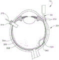
Fig. 1 illustrates an exemplary apparatus (10) configured for use in a procedure for administering a therapeutic agent to the subretinal space of a patient's eye by the suprachoroidal pathway. The instrument (10) includes a body (20) and a flexible sleeve (50) extending distally from the body (20). The sleeve (50) of the present example has a generally rectangular cross-section, although any other suitable cross-sectional profile (e.g., oval, etc.) may be used. As will be described in greater detail below, the sleeve (50) is generally configured to support the needle (100), with the needle (100) being slidable within the sleeve (50).
In this example, the sleeve (50) comprises a flexible material such as polyether block amide (PEBA) which may be manufactured under the trade name PEBAX. Of course, any other suitable material or combination of materials may be used. Also in this example, the cross-sectional profile of the sleeve (50) is about 2.0mm by 0.8mm and about 80mm in length. Alternatively, any other suitable dimensions may be used. As will be described in greater detail below, the cannula (50) is sufficiently flexible to conform to the particular configuration and contour of the patient's eye, while the cannula (50) has sufficient column strength to allow the cannula (50) to be advanced between the sclera and the choroid of the patient's eye without buckling. By way of example only, the cannula (50) may be configured and operated in accordance with at least some of the teachings of U.S. publication No. 2015/0223977 entitled "Method and Apparatus for scientific Administration of Therapeutic Agent", which is published 2015 at 8/13, the disclosure of which is incorporated herein by reference.
As seen in fig. 2-3B and 6, the cannula (50) includes a body (52), a closed distal end (54), and a side aperture (56) proximal to the distal end (54). In this example, the distal end (54) has a circular configuration. It should be appreciated that the distal end (54) may have any suitable kind of curvature. It should also be appreciated that the distal end (54) may have any other suitable kind of configuration (e.g., beveled, etc.). In this example, the distal end (54) is configured to provide separation between the scleral layer and the choroid layer to enable the cannula (50) to be advanced between such layers without causing trauma to the scleral layer or the choroid layer. Also in this example, the area of the body (52) defining the side aperture (56) is beveled, as best shown in FIGS. 3A-3B. Alternatively, the edges of the side aperture (56) may have any other suitable configuration.
As best shown in fig. 3A-3B, the needle guide (60) is disposed within the hollow interior of the cannula (50). By way of example only, the needle guide (60) may be secured within the sleeve (50) by a press or interference fit, by an adhesive, by a mechanical locking mechanism, and/or in any other suitable manner. The needle guide (60) includes a curved distal end (62) that opens to the side aperture (56) of the cannula (50) such that a lumen (64) of the needle guide (60) terminates distally at the side aperture (56). The portion of the needle guide (60) near the distal end (62) is substantially straight. The needle guide (60) may be formed of plastic, stainless steel, and/or any other suitable biocompatible material.
The needle (100) of the present example has a sharp distal tip (102) and defines a lumen (104). The distal tip (102) of the present example has a lancet configuration. In some other versions, the distal tip (102) has a tri-bevel configuration as described in U.S. publication No. 2015/0223977 entitled "Method and Apparatus for biological Administration of Therapeutic Agent," published on day 8/13 2015, the disclosure of which is incorporated herein by reference, or any other configuration. Other suitable forms that the distal tip (102) may also take will be apparent to those of ordinary skill in the art in view of the teachings herein. The needle (100) of the present example comprises a stainless steel hypodermic needle sized for delivery of the therapeutic agent while being small enough to minimize collateral trauma upon penetration of the needle (100) through the ocular tissue structures of the patient, as will be described in greater detail below. Although stainless steel is used in this example, it should be understood that any other suitable material may be used, including but not limited to nitinol, and the like.
For example only, the needle (100) may be 35 gauge with an inner diameter of 100 μm, although other suitable dimensions may be used. For example, the outer diameter of the needle (100) may fall within the range of 27 gauge to 45 gauge; or, more specifically, in the range of No. 30 to No. 42; or more specifically, in the range of No. 32 to No. 39. As another merely illustrative example, the inner diameter of the needle (100) may fall within the range of about 50 μm to about 200 μm; or more specifically, in the range of about 50 μm to about 150 μm; or more specifically, in the range of about 75 μm to about 125 μm.
A needle (100) is slidably disposed within the lumen (64) of the needle guide (60). The needle guide (60) is generally configured to direct the needle (100) upwardly through the side aperture (56) of the cannula (50) along an Exit Axis (EA) oriented obliquely to the Longitudinal Axis (LA) of the cannula (50). This is shown in the sequence depicted in fig. 3A-3B, where fig. 3A shows the needle (100) in a proximal position (where the distal tip (102) of the needle (100) is fully contained within the lumen (64) of the needle guide (60)); and fig. 3B shows the needle (100) in a distal position (with the distal tip (102) of the needle (100) outside the needle guide (60)). Although the needle (100) is flexible, the needle (100) of the present example is resiliently biased to assume a straight configuration. Thus, as shown in fig. 3B, the portion of the needle (100) extending outside the cannula (50) and the needle guide (60) is substantially straight, extending along the Exit Axis (EA). Specifically, at least a substantial length of a portion of the needle (100) extending outside the cannula (50) and the needle guide (60) is coaxially aligned with the Exit Axis (EA).
It should be understood that the depiction of the Exit Axis (EA) in FIGS. 3A-3B may be somewhat exaggerated for illustrative purposes only. In some versions, the curved distal end (62) is configured to direct the needle (100) along an Exit Axis (EA) extending distally from the cannula (50) at an angle of about 7 ° to about 9 ° relative to a Longitudinal Axis (LA) of the cannula (50). It will be appreciated that this angle may be required to bias the needle (100) direction to ensure that the needle penetrates the choroid and to minimize the likelihood that the needle (100) will continue to pass through the suprachoroidal space under the choroid (as opposed to passing completely through the choroid) and the likelihood of retinal perforation. By way of further example only, the curved distal portion (88) may urge the needle (100) away from the cannula (50) along an Exit Axis (EA) that is oriented at an angle in a range of about 5 ° to about 30 ° relative to a Longitudinal Axis (LA) of the cannula (50); or more specifically, at an angle in the range of about 5 ° to about 20 ° relative to the Longitudinal Axis (LA) of the cannula (50); or more specifically, is oriented at an angle in the range of about 5 ° to about 10 ° relative to the Longitudinal Axis (LA) of the cannula (50).
As shown in fig. 1, the instrument (10) of the present example further includes an actuation knob (26) located at the proximal end of the body (20). The actuation knob (26) is rotatable relative to the body (20) to selectively longitudinally translate the needle (100) relative to the sleeve (50). Specifically, the actuation knob (26) is rotatable in a first angular direction to distally advance the needle (100) relative to the sleeve (50); and pushing the needle (100) proximally relative to the cannula (50) in a second angular direction. By way of example only, the instrument (10) may provide such functionality through a knob (26) in accordance with at least some of the teachings of U.S. publication No. 2015/0223977 entitled "Method and Apparatus for a scientific Administration of Therapeutic Agent", published on 8/13/2015, the disclosure of which is incorporated herein by reference. Alternatively, any other suitable kind of actuation means may be used to push the needle (100) longitudinally relative to the cannula (50).
In this example, the knob (26) is rotatable through the entire range of motion corresponding to the needle (100) being advanced to a position relative to the cannula (50) to achieve a predetermined penetration in the patient's eye. In other words, the instrument (10) is configured such that the operator turns the knob (26) until the knob (26) no longer turns, or until the knob (26) begins to slip or "freewheel" in the clutch assembly, to properly position the needle (100) within the patient's eye. In some examples, the predetermined amount of advancement of the needle (100) relative to the cannula (50) is between about 0.25mm and about 10 mm; or, more specifically, in the range of about 0.1mm to about 10 mm; or more specifically, in the range of about 2mm to about 6 mm; or more specifically up to about 4 mm.
Additionally or in the alternative, the instrument (10) may be equipped with some tactile feedback feature to indicate to the operator when the needle (100) has been advanced to some predetermined distance relative to the cannula (50). Thus, the operator can determine the desired depth of penetration of the needle (100) into the patient's eye based on direct visual inspection of the markings on the instrument and/or based on tactile feedback from the instrument (10). Of course, these haptic feedback components may be combined with the present examples, as would be apparent to one of ordinary skill in the art in view of the teachings herein.
Also shown in fig. 1, a pair of feeding tubes (30, 40) extend proximally from the actuation knob (26). In this example, the first supply tube (30) is configured to couple with a source of bubble fluid (340) (e.g., BSS); and the second supply tube (40) is configured to couple with a source of therapeutic agent (341). It should be understood that each fluid supply tube (30, 40) may include a conventional luer fitting (luer feature) and/or other structure that allows the fluid supply tube (30, 40) to be coupled to a respective fluid source. The fluid supply tube (30, 40) leads to a valve assembly comprising an actuator arm (24). An actuator arm (24) is pivotable to selectively change the state of the valve assembly. Based on the pivot position of the actuating arm (24), the valve assembly is operable to selectively clamp or otherwise open/close the supply of fluid from the fluid supply tube (30, 40) to the lumen (104) of the needle (100). Accordingly, the actuation arm (24) may be operated to selectively control delivery of the bubble fluid (340) and the therapeutic agent (341) via the needle (100). By way of example only, a valve assembly may be configured and operated in accordance with at least some of the teachings of U.S. publication No. 2015/0223977 entitled "Method and Apparatus for statistical Administration of Therapeutic Agent", which is published 2015 at 8/13, the disclosure of which is incorporated herein by reference. Other suitable components and configurations that may be used to control fluid delivery via the needle (100) will be apparent to those of ordinary skill in the art in view of the teachings herein.
It will be appreciated that the features and operability of the instrument (10) may be varied in many ways. By way of example only, the needle (100) may be replaced with a needle (200) described in more detail below. Additionally, the sleeve (50) may be replaced with a sleeve (400) described in more detail below. Additionally, the instrument (10) may be modified in accordance with at least some of the teachings of the following U.S. publications: U.S. publication No. 2015/0223977 entitled "Method and Apparatus for the purification of Therapeutic Agents", published on 8/13/2015 (the disclosure of which is incorporated herein by reference); U.S. publication No. 2015/0351958 entitled "Therapeutic Agent Delivery Device with conversion Lumen" published on 10.12.2015 (the disclosure of which is incorporated herein by reference); U.S. publication No. 2015/0351959 entitled "Sub-specific indexing Needle Guide and inner" published on day 10, 12/2015 (the disclosure of which is incorporated herein by reference); U.S. publication No. 2016/0074212 entitled "Method and Apparatus for Sensing Position Between Layers of an Eye" published on day 17/3/2016 (the disclosure of which is incorporated herein by reference); U.S. publication No. 2016/0074217 entitled "Motorized Supersorial Injection of Therapeutic Agent" published on day 17/3/2016 (the disclosure of which is incorporated herein by reference); U.S. publication No. 2016/0074211 entitled "Therapeutic Agent Delivery Device with advanced Cannula and Needle," published 2016 (3, 17, 2016) (the disclosure of which is incorporated herein by reference); and/or U.S. publication No. 2016/0081849 entitled "Therapeutic Agent Delivery Device" published 24/3/2016 (the disclosure of which is incorporated herein by reference). Other suitable modifications will be apparent to persons skilled in the art in view of the teachings herein.
Exemplary methods of subretinal administration of therapeutic agents
Fig. 4A-5C illustrate an exemplary method of using the above-described apparatus (10) to deliver a therapeutic agent from the suprachoroidal pathway to the subretinal space. By way of example only, the methods described herein may be used to treat macular degeneration and/or ocular conditions. While the methods described herein are discussed in the context of treating age-related macular degeneration, it is to be understood that no such limitation is intended or implied. For example, in some alternatives, which are merely exemplary, the same techniques described herein may be used to treat retinitis pigmentosa, diabetic retinopathy, and/or other ocular conditions. In addition, it is to be understood that the methods described herein can be used to treat dry or wet age-related macular degeneration.
In this example, the method begins with the operator securing tissue (e.g., an eyelid) surrounding the patient's eye (301) using a speculum and/or any other instrument suitable for securing. Although fixation is described herein with reference to tissue surrounding the eye (301), it is understood that the eye (301) itself may remain free to move. Once the tissue around the eye (301) is fixed, the eye branch ostia (314) are inserted into the eye (301), as shown in fig. 4A, providing intraocular illumination when viewing the interior of the eye (301) through the pupil. In this example, the ocular brachial ostium (314) is located in the medial inferior quadrant, so that an supratemporal scleral incision can be made. The ocular branch ostium (314) is positioned to direct light into the interior of the eye (301) to illuminate at least a portion of the retina (e.g., including at least a portion of the macula). As will be appreciated, such illumination corresponds to a region of the eye (301) targeted for delivery of the therapeutic agent.
In this example, the branched stent port (314) is inserted only at the stage shown in fig. 4A, and the optical fiber (315) is not yet inserted into the port (314). In some other versions, the optical fiber (315) may be inserted into the branched stent opening (314) at this stage. In either case, the eye may optionally be visually inspected with a microscope to confirm that the ocular limbal stent ostium (314) is properly positioned relative to the target site. Although fig. 4A illustrates a particular positioning of the ocular brachial ostium (314), it should be understood that the ocular brachial ostium (314) can have any other positioning as will be apparent to one of ordinary skill in the art in view of the teachings herein.
Once positioned, the ostia (314) of the limbus may be accessed to the sclera (304) by dissecting the conjunctiva by cutting a flap through the conjunctiva and pulling the flap back. After such dissection is completed, the exposed surface (305) of the sclera (304) may optionally be blanched using a cauterization tool to minimize bleeding. Once the conjunctival dissection is complete, the exposed surface (305) of the sclera (304) may optionally be dried using WECK-CEL or other suitable absorption device. The eye (301) may then be marked using a template, as described in U.S. publication No. 2015/0223977 entitled "Method and Apparatus for the statistical Administration of Therapeutic Agents", published 8/13/2015, the disclosure of which is incorporated herein by reference. The operator may then attach the sewing ring assembly (332) using visual guidance created with the template and perform a sclerotomy, as shown in fig. 4B, using a conventional scalpel (313) or other suitable cutting instrument. The sclerotomy forms a small incision through the sclera (304) of the eye (301). To avoid choroidal (306) penetration, a sclerotomy is performed with special care. Accordingly, the sclerotomy provides a passageway into the space between the sclera (304) and the choroid (306). Once an incision is made in the eye (301), blunt dissection may optionally be performed to locally separate the sclera (304) from the choroid (306). As will be apparent to those of ordinary skill in the art in view of the teachings herein, such dissection may be performed using a small, blunt, elongated instrument.
By performing a sclerotomy, the operator may insert the cannula (50) of the instrument (10) through the incision (316) into the space between the sclera (304) and the choroid (306). As can be seen in fig. 4C, the cannula (50) is indexed through the sewing ring assembly (332) and into the incision. The suture ring assembly (332) may stabilize the cannula (50) during insertion. In addition, the suture ring assembly (332) maintains the cannula (50) in a generally tangential orientation relative to the incision. Such a tangential direction may reduce trauma as the guide cannula (50) passes through the incision. When the cannula (50) is inserted through the sewing ring assembly (332) into the incision, the operator may further guide the cannula (50) along the atraumatic path using forceps or other instruments. Of course, the use of forceps or other instruments is merely optional and may be omitted in some instances.
Although not shown, it should be understood that in some examples, the cannula (50) may include one or more markings on the surface of the cannula (50) to indicate different insertion depths. While only optional, such markings may be needed to help an operator identify an appropriate insertion depth when guiding the cannula (50) along an atraumatic path. For example, the operator may visually observe the location of such markings with respect to the sewing ring assembly (332) and/or with respect to the incision in the sclera (304) as an indication of the depth of insertion of the cannula (50) into the eye (301). By way of example only, one such marking may correspond to an insertion depth of the cannula (50) of approximately 6 mm.
As shown in fig. 4D, once the cannula (50) is at least partially inserted into the eye (301), the operator can insert the optical fiber (315) into the eye branch ostium (314) if the optical fiber (315) has not been inserted at this stage. With the ocular brachy-shaped stent ostium (314) in place and assembled with the optical fiber (315), an operator can visualize the interior of the eye (301) by directing light through the optical fiber (315) to activate the ocular brachy-shaped stent ostium (314) to provide illumination of the eye (301). Further adjustments to the positioning of the cannula (50) may optionally be made at this time to ensure proper positioning relative to the geographic atrophy zone of the retina (308). In some cases, the operator may wish to rotate the eye (301), such as by pulling on the suture ring assembly (332), to direct the eye (301) pupil towards the operator in order to optimize visualization of the interior of the eye (301) through the pupil.
Fig. 4C-4D show cannula (50) leading between sclera (304) and choroid (306) to the site of delivery of the therapeutic agent. In this example, the delivery site corresponds to a substantially posterior region of the eye (301) adjacent to a map-like atrophy zone of the retina (308). In particular, the delivery site of the present example is superior to the macula in the potential space between the neurosensory retina and the retinal pigment epithelium layer. By way of example only, as the cannula (50) is advanced through the range of motion shown in fig. 4C-4D, the operator may rely on direct visualization through a microscope directed through the pupil of the eye (301) with illumination provided through the optical fiber (315) and port (314). The cannula (50) is at least partially visible through a retina (308) and a choroid (306) of the eye (301). Visual tracking may be enhanced in versions where optical fibers are used to emit visible light through the distal end of the cannula (50).
Once the cannula (50) is advanced to the delivery site as shown in fig. 4D, the operator may advance the needle (100) of the instrument (10) as described above by actuating the knob (26). As shown in fig. 4E and 5A, the needle (100) is advanced relative to the cannula (50) such that the needle (100) pierces the choroid (306) without penetrating the retina (308). The needle (100) may visually appear to "tenting" the surface of the choroid (306) directly prior to penetrating the choroid (306). In other words, the needle (100) may deform the choroid (306) by pushing upward on the choroid (306), providing an appearance similar to a tent pole deforming the top of a tent. Such visual phenomena may be used by an operator to identify whether the choroid (306) is about to be punctured and the location of any eventual puncture. The amount of advancement of a particular needle (100) sufficient to initiate "tenting" and subsequent puncture of the choroid (306) may be any suitable amount, and may be determined by a number of factors, such as, but not limited to, overall patient anatomy, local patient anatomy, operator preference, and/or other factors. As noted above, the only exemplary range of needle (100) advancement may be between about 0.25mm and about 10 mm; or more specifically, between about 2mm and about 6 mm.
In this example, after the operator confirms that the needle (100) has been properly advanced by visual inspection of the tenting effect described above, the operator infuses Balanced Saline Solution (BSS) or other similar solution as the operator advances the needle (100) relative to the cannula (50). Such BSS may form a leading bubble (340) in front of the needle (100) as the needle (100) is advanced through the choroid (306). The leading bubble (340) may be required for two reasons. First, as shown in fig. 4F and 5B, the leading bubble (340) may provide an additional visual indication to the operator when the needle (100) is properly positioned at the delivery site. Second, once the needle (100) has penetrated the choroid (306), the leading bubble (340) may provide a barrier between the needle (100) and the retina (308). Such barriers may push the retinal wall outward, thereby minimizing the risk of retinal perforation as the needle (100) is advanced to the delivery site. In some versions, a foot pedal is actuated to expel a leading air bubble (340) from the needle (100). Alternatively, other suitable means for dislodging the leading bubble (340) from the needle (100) will be apparent to those of ordinary skill in the art in view of the teachings herein.
Once the pilot bubble is detected by the operator (340), the operator may stop infusing BSS, leaving a pocket of fluid, as can be seen in fig. 4F and 5B. Next, the therapeutic agent may be infused (341) by actuating a syringe or other fluid delivery device as described in the various references cited herein. The particular therapeutic agent (341) delivered may be any suitable therapeutic agent configured to treat an ocular condition. Some suitable therapeutic agents, which are merely exemplary, may include, but are not necessarily limited to, drugs having smaller or larger molecules, therapeutic cell solutions, certain gene therapy solutions, tissue plasminogen activators, and/or any other suitable therapeutic agent, as will be apparent to those of ordinary skill in the art in view of the teachings herein. By way of example only, therapeutic agent (341) may be provided in accordance with at least some of the teachings of U.S. patent No. 7,413,734 entitled "Treatment of regeneration pimentinosta with Human ubtilical core Cells," published on 19.8.2008, the disclosure of which is incorporated herein by reference. In addition to or instead of being used to deliver therapeutic agents (341), the apparatus (10) and variations thereof may be used to provide drainage and/or perform other operations.
In this example, the amount of therapeutic agent (341) ultimately delivered to the delivery site is about 50 μ L, although any other suitable amount may be delivered. In some versions, a foot pedal is actuated to expel therapeutic agent (341) from needle (100). Alternatively, other suitable means for expelling the medicament (341) from the needle (100) will be apparent to one of ordinary skill in the art in view of the teachings herein. As can be seen in fig. 4G and 5C, the delivery of therapeutic agent (341) can be visualized by expansion of the fluid pouch. As shown, when the therapeutic agent (341) is injected into the suprachoroidal space, the subretinal space, the therapeutic agent (341) substantially mixes with the fluid of the leading bubble (340).
Once delivery is complete, the needle (100) may be retracted by turning the knob (26) in a direction opposite to that used to advance the needle (100); the cannula (50) may then be withdrawn from the eye (301). It should be appreciated that due to the size of the needle (100), the site where the needle (100) passes through the choroid (306) is self-sealing, such that no further steps need to be taken to seal the delivery site through the choroid (306). The suture loop assembly (332) and the dendritic stent (314) may be removed and any suitable conventional technique may be used to close the incision in the sclera (304).
As noted above, the above method can be performed to treat a patient suffering from macular degeneration. In some such cases, the therapeutic agent (341) delivered by the needle (100) may comprise cells derived from the postpartum umbilicus and placenta. As noted above, and by way of example only, therapeutic agent (341) may be provided in accordance with at least some of the teachings of U.S. patent No. 7,413,734 entitled "Treatment of diagnosis pimentinosta with Human u membrane core Cells", published on 19.8.2008, the disclosure of which is incorporated herein by reference. Alternatively, the needle (100) may be used to deliver any other suitable substance or substances in addition to or in place of those described in U.S. patent No. 7,413,734 and/or elsewhere herein. By way of example only, therapeutic agent (341) may comprise a variety of drugs including, but not limited to, small molecules, macromolecules, cells, and/or gene therapy agents. It should also be understood that macular degeneration is merely one illustrative example of a condition that may be treated by the methods described herein. Other biological conditions that may be addressed using the apparatus and methods described herein will be apparent to those of ordinary skill in the art.
It should also be understood that the above-described method may be performed according to any of the teachings of the following U.S. publications: U.S. publication No. 2015/0223977 entitled "Method and Apparatus for the purification of Therapeutic Agents", published on 8/13/2015 (the disclosure of which is incorporated herein by reference); U.S. publication No. 2015/0351958 entitled "Therapeutic Agent Delivery Device with conversion Lumen" published on 10.12.2015 (the disclosure of which is incorporated herein by reference); U.S. publication No. 2015/0351959 entitled "Sub-specific indexing Needle Guide and inner" published on day 10, 12/2015 (the disclosure of which is incorporated herein by reference); U.S. publication No. 2016/0074212 entitled "Method and Apparatus for Sensing Position Between Layers of an Eye" published on day 17/3/2016 (the disclosure of which is incorporated herein by reference); U.S. publication No. 2016/0074217 entitled "Motorized Supersorial Injection of Therapeutic Agent" published on day 17/3/2016 (the disclosure of which is incorporated herein by reference); U.S. publication No. 2016/0074211 entitled "Therapeutic Agent Delivery Device with advanced Cannula and Needle," published 2016 (3, 17, 2016) (the disclosure of which is incorporated herein by reference); and/or U.S. publication No. 2016/0081849 entitled "Therapeutic Agent Delivery Device" published 24/3/2016 (the disclosure of which is incorporated herein by reference).
Exemplary replacement needle for instruments
There are several variables that may affect the relationship between the exit angle of the needle (100) and the choroid (306) of any given patient. It is understood that the choroid (306) and retina (308) are very thin and have relatively little structural integrity. Thus, even when a very pliable cannula (50) is used, the cannula (50) may tend to provide a substantial separation between the choroid (306) and the sclera (304) when the cannula (50) is inserted between the choroid (306) and the sclera (304). The degree of separation may vary from patient to patient (e.g., based on normal anatomical changes and/or based on the disease state of the patient, etc.). Where separation is indeed large, the exit angle of the needle (100) may not be sufficient to cause the distal tip (102) to pass completely through the choroid (306). In other words, the needle (100) may continue through the suprachoroidal space without completely penetrating the choroid (306).
Fig. 6 shows an exemplary situation where the cannula (50) has lifted the choroid (306) and retina (308) away from the sclera (304) to a point defining a large gap (305) between the sclera (304) and the choroid (306). As also shown in fig. 6, the exit angle is oriented such that the needle (100) does not penetrate the choroid (306); and further to bring the needle (100) into final engagement with the sclera (304). Fig. 7 shows the needle (100) advanced distally along the exit angle. As shown, the needle (100) passes tangentially along the choroid (306) without ever damaging the choroid (306). In some other cases, the needle (100) may pass partially through the choroid (306) and immediately exit the choroid (306) without ever reaching the sub-retinal space between the choroid (306) and the retina (308).
If the operator determines (e.g., based on the absence of a choroidal "bump" observation as described above) that the needle (100) has not completely penetrated the choroid (306) despite the needle (100) being fully advanced distally, the operator may retract the needle (100) proximally, reposition the cannula (50) and/or another portion of the instrument (10) slightly to provide a better orientation for the exit angle, and then attempt to advance the needle (100) distally again. Even with such efforts, it may still be difficult or even impossible in some cases to successfully penetrate the choroid (306) with the needle (100). Even in the case of successful repositioning efforts, the success rate may be highly dependent on the skill of the operator, and repositioning efforts will increase the time of the method. Furthermore, repositioning may increase the risk of tissue trauma, increase the risk of bubble collapse, and/or increase the risk of cell egress to the suprachoroidal space.
It appears obvious to solve the above problem by simply modifying the needle guide (60) to provide a steeper exit angle. However, such modifications may not be appropriate for many patients. Specifically, increasing the exit angle by providing a more pronounced bend at the distal end (62) of the needle guide (60) may increase the risk of the needle (100) passing through the retina (308) in some patients, particularly in those patients in which the gap (305) created by the cannula (50) between the sclera (304) and choroid (306) is less pronounced than the gap (305) shown in fig. 6-7; including the case where the gap (305) is not present. Thus, it may be desirable to provide a more subtle solution that provides greater consistency in choroidal (306) penetration without substantially increasing the risk of retinal (308) penetration. Such solutions may provide better adaptability of anatomical changes between patients; accommodate variations in operator skill and expertise, and minimize the level of operator training required.
Fig. 8 shows an exemplary alternative needle (200) that may be incorporated into the instrument (10) in place of needle (100). In some cases, needle (200) may replace needle (100) without modifying any other aspect of instrument (10). The needle (200) of the present example has a distal tip (202) that is configured and operates just as the distal tip (102) described above. As shown in fig. 9A-9C, needle (200) further defines a lumen (204) that is configured and operates just as lumen (104) described above. However, unlike the needle (100), the needle (200) of the present example includes a substantially straight proximal portion (210), a substantially straight distal portion (212), and a curved portion (214) between the proximal and distal portions (210, 212). In the present example, the needle (200) is formed of nitinol, although it should be understood that any other suitable material (e.g., stainless steel, etc.) may be used.
The needle (200) is configured to provide the curved portion (214) as a pre-formed component such that the needle (200) is resiliently biased to assume the configuration shown in fig. 6. By way of example only, the curved portion (214) may be configured to have a constant radius of curvature of between about 4mm and about 15 mm; a constant radius of curvature between about 7mm and about 12 mm; a constant radius of curvature between about 8mm and about 11 mm; or a constant radius of curvature between about 9mm and about 10 mm. In some versions, the curved portion (214) has a radius of curvature of about 10.5 mm. In some other versions, the curved portion (214) has a radius of curvature of about 10.0 mm. In some other versions, the curved portion (214) has a radius of curvature of about 9.5 mm. It will be appreciated that the radius of curvature must be carefully selected, since if the radius is too small, the risk of perforation of the retina (308) may increase; if the radius is too large, the needle (200) may still not be able to penetrate the choroid (306) completely.
While the radius of curvature of the curved portion (214) is constant in this example, in some other versions the radius of curvature may be variable. For example, some variations of the needle (200) may provide a larger radius of curvature in the region where the needle (200) is still disposed within the cannula (50), even when the needle (200) is in the distally-extended position; a smaller radius of curvature is provided in the region where the needle (200) extends distally from the cannula (50) when the needle (200) is in the distally extended position. This configuration may impart a slight pre-curvature to the cannula (50), which may further help the cannula (50) conform to the curved inner wall of the sclera (304), which in turn may reduce the presence (or size) of the gap (305).
As shown in fig. 9A-9C, the needle (200) is slidably disposed in a needle guide (60) within the cannula (50). While fig. 9A shows needle (200) in a partially advanced state, it should be understood that needle (200) may be further retracted proximally into needle guide (60) such that distal tip (202) does not protrude through side aperture (56). As shown in FIG. 9A, as the needle (200) begins to exit the cannula (50) via the side aperture (56), the distal projection of the needle (200) follows a first Exit Axis (EA)1) And (4) orientation. At this stage, the curved portion (214) and a portion of the distal portion (212) remain housed within the needle guide (60) such that the needle guide (60) prevents the needle (200) from reaching the configuration shown in fig. 8.
As the operator continues to advance the needle (200) distally relative to the cannula (50), as shown in FIG. 9BAs shown, needle (200) protrudes more distally from side aperture (56). Due to the resilient biasing of the needle (200), the needle (200) now has a longer projection along the second Exit Axis (EA)2) And (4) orientation. Second Exit Axis (EA)2) Defining an angle with the Longitudinal Axis (LA) greater than that at the first Exit Axis (EA)1) And a Longitudinal Axis (LA). As the operator continues to advance the needle (200) distally relative to the cannula (50), the needle (200) protrudes even more distally from the side aperture (56) as shown in FIG. 9C. Due to the resilient biasing of the needle (200), the needle (200) now has a longer projection along the third Exit Axis (EA)3) And (4) orientation. Third Exit Axis (EA)3) Defining an angle with the Longitudinal Axis (LA) greater than that at the second Exit Axis (EA)3) And a Longitudinal Axis (LA). Thus, the more needles (200) advanced, the greater the angle defined between the Exit Axis (EA) and the Longitudinal Axis (LA). It should be understood that the pair of Exit Axes (EA) in FIGS. 9A-9C1、EA2、EA3) The depiction may be somewhat exaggerated for illustrative purposes only.
As shown in fig. 10, needle (200) is particularly useful where the cannula creates a large gap (305) between the sclera (304) and the choroid (306). It should be understood that the gap (305) in fig. 10 is substantially the same as the gap (305) in fig. 7. As mentioned above, the needle (100) cannot penetrate the choroid (306) due to the gap (305) in fig. 7 and the relative relationship between the anatomy and the instrument (10) structure. However, as shown in fig. 10, the curvature of the needle (200) allows the needle (200) to penetrate the choroid (306) despite the gap (305) and the relative relationship between the anatomy and the instrument (10) structure.
As mentioned above, the exit angle of the needle (200) varies depending on the extent to which the needle (200) extends from the cannula (50). It will be appreciated that such variation in exit angle will allow the operator to control the optimum exit angle by controlling the amount that the needle (200) extends. This may allow for shallower angles (less extension) for some patients and steeper angles (more extension) for others to more consistently enable penetration of the choroid (306) in a relatively safe and effective manner, thereby eliminating the need for other mitigation or adaptation methods that would otherwise be required from the situation depicted in fig. 7.
Exemplary cannula needle of the Instrument
As described above, the cannula (50) includes a closed distal end (54) and a side aperture (56) proximal to the distal end (54). In some cases, it may be desirable to provide an alternative cannula having an open distal end without a side aperture. This may provide, for example only, a simplified manufacturing process. Because it may still be necessary to move the needle away from the cannula so that the distal tip of the needle is oriented along an axis oblique to the longitudinal axis of the cannula, it may be desirable to use a needle having a pre-formed curve in versions of the cannula having an open distal end.
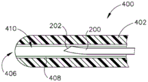
Fig. 11A shows an exemplary alternative cannula (400) that may be easily incorporated into the instrument (10) in place of the cannula (50). The cannula (400) of this example has a flexible body (402) and a distal aperture (406). In this example, the distal aperture (406) is coaxially positioned on the longitudinal axis of the cannula (400). In some other versions, the distal aperture (406) is offset from a longitudinal axis of the cannula (400). By way of example only, the sleeve (400) may be formed from polyether block amide (PEBA) and/or any other suitable type of material. As with the cannula (50), the cannula (400) of the present example has sufficient column strength to advance distally between the sclera (306) and the choroid (308) of the patient's eye without buckling.
The insert (408) is located within the sleeve (400). The insert (408) may be secured within the sleeve (400) by a press or interference fit, by an adhesive, by a mechanical locking mechanism, and/or in any other suitable manner. In this example, the insert (408) is formed of a polyimide material, although it is understood that any other suitable biocompatible material may be used. The insert (408) of the present example is substantially straight, but may curve with the cannula (400). The needle (200) is slidably disposed within a lumen (410) defined by an insert (408). As shown in fig. 11A, with the needle (200) in the proximal position, the distal tip (202) of the needle (200) is fully contained within the lumen (410). At this stage, the insert (408) receives the needle (200) such that the needle (200) remains in a substantially straight configuration under pressure. As shown in fig. 11B, with the needle (200) in the distal position, the distal tip (202) of the needle is distal to the cannula (400). At this stage, the curved portion (214) is exposed such that the distal portion (212) of the needle (200) is oriented along an exit axis that is oblique to the longitudinal axis of the cannula (400). It is understood that such a configuration and orientation may position the distal tip (202) in the subretinal space (i.e., between the choroid (306) and the retina (308)).
V. exemplary combination
The following examples are directed to various non-exhaustive ways in which the teachings herein may be combined or applied. It should be understood that the following examples are not intended to limit the scope of any claims, which may be presented at any time or in subsequent documents of the application. There is no disclaimer. The following examples are provided for illustrative purposes only. It is contemplated that the various teachings herein may be arranged and applied in many other ways. It is also contemplated that some variations may omit certain features mentioned in the following embodiments. Thus, the aspects or features mentioned below should not be considered critical unless the inventor or successor of interest to the present invention explicitly indicates otherwise. If any claim is made in this application or a subsequent document related to this application that includes other features than those mentioned below, it should not be presumed that those additional features are added for any reason related to patentability.
Example 1
An apparatus, comprising: (a) a main body; (b) a cannula extending distally from the body, wherein the cannula is flexible; and (c) a needle slidably disposed within the cannula, wherein the needle comprises: (i) a sharp distal tip, wherein the needle is configured to translate relative to the cannula between a proximal position and a distal position, wherein the distal tip is configured to be inside the cannula when the needle is in the proximal position, wherein the distal tip is configured to be outside the cannula when the needle is in the distal position, and (ii) a curved portion, wherein the needle is resiliently biased to extend along a curve through the curved portion.
Example 2
The apparatus of embodiment 1, wherein the cannula comprises: (i) a closed distal end, and (ii) a side aperture proximal to the closed distal end.
Example 3
The device of embodiment 2 wherein the sleeve further comprises a ramp member, wherein the ramp member extends from an interior region of the sleeve to the side aperture.
Example 4
The device of any one or more of embodiments 1-3, wherein the curved portion is resiliently biased to define a constant radius of curvature.
Example 5
The device of embodiment 4, wherein the radius of curvature is between about 7mm and about 12 mm.
Example 6
The device of embodiment 4, wherein the radius of curvature is between about 4mm and about 15 mm.
Example 7
The device of embodiment 4, wherein the radius of curvature is between about 9mm and about 10 mm.
Example 8
The device of any one or more of embodiments 1-7, wherein the curved portion is configured to position the distal tip at an increasing exit angle relative to a longitudinal axis of the cannula based on a distance the needle is advanced distally relative to the cannula.
Example 9
The device of any one or more of embodiments 1-8, wherein the bending portion comprises a first bending region and a second bending region, wherein the first bending region is located near a distal portion of the needle, wherein the second bending region is located proximal to the first bending region.
Example 10
The apparatus of embodiment 9, wherein the first curved region has a first radius of curvature, wherein the second curved region has a second radius of curvature, wherein the second radius of curvature is greater than the first radius of curvature.
Example 11
The apparatus of any one or more of embodiments 9-10, wherein the first bending region is configured to not impart curvature to the cannula, wherein the second bending region is configured to impart curvature to the cannula.
Example 12
The device of any one or more of embodiments 1-11, wherein the needle further comprises a straight proximal portion and a straight distal portion, wherein the curved portion is positioned longitudinally between the straight proximal portion and the straight distal portion.
Example 13
The device of any one or more of embodiments 1-12, wherein the cannula defines an open distal end.
Example 14
The device of embodiment 13, wherein the needle is configured to protrude from the open distal end of the cannula when the needle is in the distal position.
Example 15
The device of any one or more of embodiments 1-14, further comprising a source of a liquid therapeutic agent, wherein the needle is operable to deliver the liquid therapeutic agent.
Example 16
The apparatus of embodiment 15, wherein the body comprises: (i) a needle actuator, wherein the actuator is operable to push the needle longitudinally relative to the cannula; and (ii) a valve member, wherein the valve member is operable to selectively provide fluid communication from the source of liquid therapeutic agent to the needle.
Example 17
An apparatus, comprising: (a) a main body; (b) a cannula extending distally from the body, wherein the cannula is flexible, wherein the cannula comprises: (i) a closed distal end, and (ii) a side aperture proximal to the closed distal end; and (c) a needle slidably disposed within the cannula, wherein the needle comprises: (i) a sharpened distal tip, wherein the needle is configured to translate relative to the cannula between a proximal position and a distal position, wherein the distal tip is configured to be located inside the cannula when the needle is in the proximal position, wherein the distal tip is configured to extend through the side aperture when the needle is in the distal position, and (ii) a curved portion, wherein the curved portion is configured to provide a beveled exit angle for a portion of the needle extending through the side aperture when the needle is in the distal position.
Example 18
The device of embodiment 17, wherein the curved portion is resiliently biased to assume a curved configuration, wherein the curved portion is further configured to deform within the cannula to a substantially straight configuration when the needle is in the proximal position.
Example 19
A method of administering a therapeutic agent to an eye of a patient, wherein the eye comprises a sclera, a choroid, and a retina, the method comprising: (a) inserting a flexible cannula between the sclera and the choroid; (b) advancing a needle relative to the cannula such that a distal tip of the needle penetrates the choroid, wherein the needle comprises a pre-formed curve, wherein the curve directs the needle toward a targeted region of the choroid; and (c) administering the therapeutic agent to the area between the choroid and the retina via the needle.
Example 20
The method of embodiment 19, wherein the act of advancing the needle comprises: (i) advancing the needle relative to the cannula to a first longitudinal position in which the needle defines a first exit angle relative to the cannula, and (ii) further distally advancing the needle relative to the cannula to a second longitudinal position in which the needle defines a second exit angle relative to the cannula, wherein the second exit angle is greater than the first exit angle.
VI, miscellaneous items
It should be understood that any of the types of instruments described herein may include various other components in addition to or in place of those described above. By way of example only, any of the devices herein may also include one or more of the various components disclosed in any of the various references incorporated by reference herein.
It is to be understood that any one or more of the teachings, expressions, embodiments, examples, etc. described herein can be combined with any one or more of the other teachings, expressions, embodiments, examples, etc. described herein. Therefore, the above-described teachings, expressions, embodiments, examples, etc. should not be considered in isolation from each other. Various suitable ways in which the teachings herein may be combined will be apparent to those of ordinary skill in the art in view of the teachings herein. Such modifications and variations are intended to be included within the scope of the appended claims.
It should be understood that any patent, publication, or other disclosure material, in whole or in part, that is said to be incorporated by reference herein is incorporated herein only to the extent that the incorporated material does not conflict with existing definitions, statements, or other disclosure material set forth in this disclosure. Accordingly, and to the extent necessary, the disclosure as explicitly set forth herein supersedes any conflicting material incorporated herein by reference. Any material, or portion thereof, that is said to be incorporated by reference herein, but which conflicts with existing definitions, statements, or other disclosure material set forth herein is only incorporated to the extent that no conflict arises between that incorporated material and the existing disclosure material.
The above-described version may be designed to be disposed of after a single use, or it may be designed to be used multiple times. In either or both cases, the pattern may be reconditioned for reuse after at least one use. The repair may include any combination of the following steps: the equipment is disassembled and then the particular parts are cleaned or replaced and then reassembled. In particular, certain types of devices may be disassembled, and any number of the particular pieces or parts of the device may be selectively replaced or removed in any combination. After cleaning and/or replacement of particular components, certain versions of equipment may be reassembled for subsequent use either at a reconditioning facility, or by an operator immediately prior to an operation. Those skilled in the art will appreciate that reconditioning of a device can utilize a variety of techniques for disassembly, cleaning/replacement, and reassembly. The use of such techniques and the resulting repair devices are within the scope of the present application.
By way of example only, versions described herein may be sterilized before and/or after operation. In one sterilization technique, the device is placed in a closed, sealed container, such as a plastic or TYVEK bag. The container and apparatus may then be placed in a radiation field, such as gamma radiation, x-rays, or a high energy electron field, that may penetrate the container. The radiation may kill bacteria on the device and in the container. The sterilized device may then be stored in a sterile container for later use. The device may also be sterilized using any other technique known in the art, including but not limited to beta or gamma radiation, ethylene oxide, or steam.
While various embodiments of the present invention have been shown and described, further modifications to the methods and systems described herein can be accomplished by appropriate modifications by one of ordinary skill in the art without departing from the scope of the invention. Several such possible modifications have been mentioned, and others will be apparent to those skilled in the art. For example, the examples, embodiments, geometries, materials, dimensions, ratios, steps, etc., discussed above are illustrative and not required. The scope of the present invention should, therefore, be considered in terms of the claims and is not to be construed as limited to the details of structure and operation shown and described in the specification and drawings.