CN108701533B - Wireless power transfer system - Google Patents
Wireless power transfer system Download PDFInfo
- Publication number
- CN108701533B CN108701533B CN201680079172.XA CN201680079172A CN108701533B CN 108701533 B CN108701533 B CN 108701533B CN 201680079172 A CN201680079172 A CN 201680079172A CN 108701533 B CN108701533 B CN 108701533B
- Authority
- CN
- China
- Prior art keywords
- insulator
- string
- resonator
- coil
- devices
- Prior art date
- Legal status (The legal status is an assumption and is not a legal conclusion. Google has not performed a legal analysis and makes no representation as to the accuracy of the status listed.)
- Active
Links
Images


Classifications
-
- H—ELECTRICITY
- H01—ELECTRIC ELEMENTS
- H01F—MAGNETS; INDUCTANCES; TRANSFORMERS; SELECTION OF MATERIALS FOR THEIR MAGNETIC PROPERTIES
- H01F38/00—Adaptations of transformers or inductances for specific applications or functions
- H01F38/14—Inductive couplings
-
- H—ELECTRICITY
- H01—ELECTRIC ELEMENTS
- H01F—MAGNETS; INDUCTANCES; TRANSFORMERS; SELECTION OF MATERIALS FOR THEIR MAGNETIC PROPERTIES
- H01F27/00—Details of transformers or inductances, in general
- H01F27/24—Magnetic cores
-
- H—ELECTRICITY
- H01—ELECTRIC ELEMENTS
- H01F—MAGNETS; INDUCTANCES; TRANSFORMERS; SELECTION OF MATERIALS FOR THEIR MAGNETIC PROPERTIES
- H01F27/00—Details of transformers or inductances, in general
- H01F27/28—Coils; Windings; Conductive connections
-
- H—ELECTRICITY
- H01—ELECTRIC ELEMENTS
- H01F—MAGNETS; INDUCTANCES; TRANSFORMERS; SELECTION OF MATERIALS FOR THEIR MAGNETIC PROPERTIES
- H01F27/00—Details of transformers or inductances, in general
- H01F27/28—Coils; Windings; Conductive connections
- H01F27/32—Insulating of coils, windings, or parts thereof
-
- H—ELECTRICITY
- H02—GENERATION; CONVERSION OR DISTRIBUTION OF ELECTRIC POWER
- H02J—CIRCUIT ARRANGEMENTS OR SYSTEMS FOR SUPPLYING OR DISTRIBUTING ELECTRIC POWER; SYSTEMS FOR STORING ELECTRIC ENERGY
- H02J50/00—Circuit arrangements or systems for wireless supply or distribution of electric power
- H02J50/10—Circuit arrangements or systems for wireless supply or distribution of electric power using inductive coupling
- H02J50/12—Circuit arrangements or systems for wireless supply or distribution of electric power using inductive coupling of the resonant type
Landscapes
- Engineering & Computer Science (AREA)
- Power Engineering (AREA)
- Computer Networks & Wireless Communication (AREA)
- Charge And Discharge Circuits For Batteries Or The Like (AREA)
Abstract
A novel and advantageous insulator disk with embedded resonator coil is provided. By serially linking the insulator disks using a suitable mechanical mechanism, the insulator disks form an insulator or insulator string for a high power transmission line system. The resonator coils embedded inside the insulator disc thus form a string of relay resonators, which can be used for wireless power transfer by the principle of near field magnetic coupling and resonance. The insulator string may provide simultaneous functions of voltage isolation and wireless power transfer over the length of the string. Applications include, but are not limited to, wireless power transfer in high voltage environments, such as those encountered in high voltage power transmission line systems.
Description
Cross Reference to Related Applications
This application claims priority and benefit from U.S. provisional patent application serial No. 62/256,726 filed 11/18/2015, which is incorporated herein by reference in its entirety, including any figures, tables, and drawings.
Technical Field
The present invention relates to a wireless power transfer system suitable for a high voltage power transmission line system.
Background
Smart grids and internet of things have promoted active research in recent years to establish online monitoring systems for power transmission systems. Such monitoring systems are particularly important and critical for some areas such as, for example, china, which has suffered several large scale blackouts in recent years due to heavy storm snow in the middle and north of china and typhoons in the south of china. A power outage in china in 2008 results in an estimated total economic loss of over 1000 billion RMB (approximately US $650 billion). The severity of the blackout problem in china has led to an increasing research in china on improving the online monitoring of power transmission systems using monitoring devices and systems installed on the towers of the power transmission systems.
Online monitoring systems for power transmission towers and cables encompass a range of monitoring services such as electrical parameters (e.g. voltage, current, phase angle and power), mechanical parameters (e.g. tower structure, cable waving (galloping), ice/snow thickness and wind induced mechanical vibrations of the transmission tower), thermal parameters (e.g. cable temperature) and weather information (e.g. wind speed, temperature and lightning, and pollution level) and theft monitoring.
Some known monitoring systems for high voltage power transmission systems are powered by solar panel units mounted on the power transmission tower. One problem with such forms of power supply is the intermittency of available solar energy, which deteriorates during periods of inclement weather, which can lead to depletion of the charge in the battery of the solar panel unit and thus power down of the monitoring system.
R, Berthaume and R, Blais, "Microwave repeater Power supplied tapped from the overhead ground wire on 735 kV transmission lines," IEEE Trans. Power APP. Syst., vol. PAS-99, No.1, pp. 183-.
A. Kurs, A. Karalis, R. Moffatt, J.D. Joannopoulos, P. Fisher, and M. Soljacic, "Wireless power transfer via string coupled magnetic responses," Science, vol. 317, No.5834, pp. 83-86, 2007, month 7, disclose a medium-range Wireless power transfer technique using magnetic resonance. The magnetic resonance wireless Power Transfer technique disclosed by Kurs employs a Maximum Power Transfer Principle (Maximum Power Transfer Principle) that has limitations on poor system efficiency. For any circuit operating with the maximum power transfer theorem via an impedance matched to the source impedance, there is an inherent limitation that the energy efficiency of the system cannot be higher than 50%. For transmission distances of about 2 meters, the system energy efficiency is optimally 15%, as discussed in S.Y.R. Hui, W.X. Zhong and C.K. Lee, "A critical view of recovery progress in mid-range wireless Power transfer", IEEE transfer on Power Electronics, Vol.29, No.9, 9 months of 2014, pp: 4500-.
Wireless domino resonator wireless power transfer systems have been disclosed in:
[1] s.y.r. Hui and w.x. Zhong, "Apparatus and Method for Wireless Power Transfer", patent application PCT/IB2011/000050, 2011, 1 month and 14 days;
[2] W.X. Zhong, C.K. Lee and S.Y.R. Hui, "General Analysis on the Use of Tesla's detectors in Domino Forms for Wireless Power Transfer", IEEE Transactions on Industrial Electronics, Vol.60, No.1, month 1 2013, pp: 261-;
[3] C.K. Lee, W.X. Zhong and S.Y.R. Hui, "Effects of Magnetic Coupling of Non-additive detectors on Wireless Power System", IEEE Transactions on Power Electronics, Volume 27, Issue 4, 2012, Page(s) 1905-
[4] W.X. Zhong, C.K. Lee and S.Y.R. Hui, "Wireless Power Domino-reactor Systems with Non-coaxial operators and Circular Structures", IEEE Transactions on Power Electronics, Volume 27, Issue 11, 2012, Page(s): 4750-.
It has been practically demonstrated that the wireless domino resonator systems in [1] to [4] provide an efficient way of transferring wireless power within a few meters. Unlike the Kurs proposal, the wireless domino resonator system employs the principle of maximum energy efficiency and can achieve overall system energy efficiency of greater than 50%. One advantage of the wireless domino resonator system is that the resonators can be flexibly arranged to direct wireless power flow rather than being limited to straight power transfer.
In view of the increasing demand for powering online monitoring systems for power transmission towers and transmission lines, there is a need for new isolator structures that can provide (1) High Voltage (HV) isolation and (2) Wireless Power Transfer (WPT) capabilities.
Disclosure of Invention
In an embodiment, the insulator device comprises: a body formed of an electrically insulating material, the body defining a cavity; and a resonator coil located within the cavity, the coil configured for resonant inductive coupling with a similar such coil when placed in proximity thereto.
In another embodiment, the insulator comprises a string of connected insulator devices, each of a plurality of said strings of insulator devices comprising a body formed of an electrically insulating material, said body defining a cavity; and a resonator coil located within the cavity, the coil configured for resonant inductive coupling with a like such coil when placed in proximity to the like such coil, wherein a plurality of insulator devices have the resonator coil arranged within a string of devices, enabling near field transmission of electrical energy from a first end of the string to a second end of the string.
In another embodiment, a wireless power transfer system includes: an insulator having a string of connected insulator devices, each of a plurality of the strings of insulator devices comprising a body formed of an electrically insulating material, the body defining a cavity, and a resonator coil located within the cavity, the coil configured for resonant inductive coupling with a like such coil when placed in proximity thereto; an energy transfer coil magnetically coupled to a first resonator coil insulator device of the connected insulator device string for wirelessly transferring electrical energy to the first resonator coil insulator device; and an energy receiving coil magnetically coupled to a last resonator coil insulator device of the connected string of insulator devices for wirelessly receiving electrical energy from the last resonator coil insulator device, wherein a plurality of insulator devices having resonator coils are arranged within the string of devices, thereby enabling near field transmission of electrical energy from a first end of the string to a second end of the string.
In another embodiment, a method of monitoring a power transmission line includes providing the power transmission line with a monitoring device powered by electrical energy harvested from a power line and transmitted to the monitoring device using a wireless power transfer system as described herein (e.g., the wireless power transfer system of the preceding paragraph).
Other aspects of the invention are according to the appended claims.
This summary of the invention does not necessarily disclose all features necessary to define the invention; the invention may reside in a subcombination of the disclosed features.
Drawings
The foregoing and other features of the invention will be apparent from the following description of preferred embodiments, which is provided by way of example only with reference to the accompanying drawings, in which:
figure 1 shows a known direct wireless power domino resonator system;
fig. 2 shows a known curved wireless power domino resonator system;
figure 3 shows a typical insulation for a high voltage power transmission system tower;
figures 4a and 4b show a known tempered glass insulator disc and an insulator comprising a string of connected insulator discs, respectively, for a high voltage power transmission system tower;
figures 5a and 5b show schematic cross-sectional views of a known insulator disc and an insulator comprising a string of connected insulator discs, respectively, for a high voltage power transmission system tower;
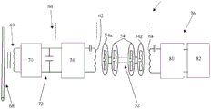
FIG. 6 is a schematic block diagram of a wireless power transfer system in accordance with an embodiment of the subject invention;
figure 7 illustrates energy harvesting points and energy receiving points on a high voltage power transmission system tower for a wireless power transfer system according to an embodiment of the subject invention;
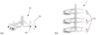
FIGS. 8a and 8b illustrate an insulator disk and an insulator including a string of connected insulator disks, respectively, according to embodiments of the subject invention;
FIG. 9 illustrates a portion of a flexible insulator including a string of insulator disks with a portion of each insulator disk removed to show a resonator coil embedded therein in accordance with an embodiment of the subject invention; and
fig. 10 depicts an insulator for a high voltage power transmission tower, according to an embodiment of the subject invention.
Detailed Description
The following description is by way of example only and is not limited to the description of the preferred embodiments in terms of the combination of features required to implement the invention.
Fig. 1 shows a known direct wireless power transfer domino resonator system 10 consistent with the above disclosure of [1] to [4 ]. The system 10 has a plurality of LC resonator coils 12 arranged in series on a support 14 at linear intervals such that adjacent coils 12 become magnetically coupled to wirelessly transfer electrical energy from a first coil 12a in the string to a last coil 12z in the string.
Fig. 2 shows a known curved wireless power transfer domino resonator system 20 consistent with the above disclosure [1] to [4 ]. The system 20 also has a plurality of LC resonator coils 22 arranged in spaced series on a support 24, but it is arranged in a curve to illustrate that it is possible for magnetically coupled adjacent coils 22 to transfer power wirelessly through a curved path from the first coil 22a in the string to the last coil 22z in the string.
Fig. 3 shows a power transmission line system tower 30 supporting a plurality of high voltage power lines 32 by means of known insulators 34. As better seen in fig. 4a and 4b and fig. 5a and 5b, the insulator 34 comprises a series of connected insulator disks 36, although these figures depict only one type of power transmission line system insulator.
Referring to fig. 5a, each insulator disk 36 has a cap 38 defining a ball socket (ball socket), and a center pin 40 having a ball 42 at its exposed end, the center pin 40 being glued or otherwise affixed in a cavity in a porcelain or glass body 44, wherein the insulator 44 has an insulated head 46 that separates and insulates the ball socket from the center pin 40. Referring to fig. 5b, two insulator disks 36 may be arranged in series by inserting the ball 42 of one disk 36 into the socket of an adjacent disk 36. It will be understood that: fig. 3 to 5 are only illustrations of one form of insulator 34 and other forms are known, which employ different methods of connection, but share the following features: the string of disks 36 forming the insulator 34 provides an insulator 34 that can not only provide insulation from other transmission components including towers for high voltage power transmission lines, but also act as a mechanical device supporting the power transmission lines.
Embodiments of the subject invention relate to new structures for insulator disks with embedded resonator coils. The insulator disks form an insulator, insulator string, or insulator rod for a high power transmission line system by linking the insulator disks in series using a suitable mechanical mechanism. The resonator coils embedded within the insulator disc thus form a series of relay resonators (relay resonators) that can be used for wireless power transfer by the principle of near field magnetic coupling and resonance. Such an insulator string may provide simultaneous functions of voltage insulation and wireless power transfer over the length of the string or rod. Applications of embodiments of the subject invention are particularly applicable to, but not limited to, wireless power transfer in high voltage environments, such as those encountered in high voltage power transmission line systems.
Fig. 6 provides a schematic block diagram of a wireless power transfer system 50 in accordance with an embodiment of the subject invention. The system 50 includes an insulator 52 formed from a series of connected insulator devices, such as insulator disks 54. As shown in fig. 8a, each of the string of a plurality of said insulator devices 54 comprises a body 56 formed of an electrically insulating material, said body 56 defining a cavity 58. A resonator coil 60 is located within the cavity 58, wherein the coil 60 is configured for resonant inductive coupling with a similar such coil when placed in proximity thereto. The plurality of insulator devices 54 with embedded resonator coils 60 may include a subset of a string of insulator devices such that not all insulator devices or pads in the string include a resonator coil 60. However, in many embodiments, all of the insulator disks 54 are provided with resonator coils 60.
The wireless power transfer system 50 may include an energy transfer coil 62 magnetically coupled to a first resonator coil insulator device 54a of the connected insulator device string for wirelessly transferring electrical energy to the first resonator coil insulator device 54 a. An energy receiving coil 64 is also provided that is magnetically coupled to the last resonator coil insulator device 54z of the connected insulator device string for wirelessly receiving electrical energy from the last resonator coil insulator device 54 z. A plurality of isolator devices 54 having resonator coils 60 are arranged within a string of devices, enabling near field transmission of electrical energy from a first end of the string to a second end of the string, and vice versa in some systems, i.e., the system 10 may be configured to be bidirectional.
The energy transfer resonator coil 62 comprises a portion of an energy harvesting circuit 66, the energy harvesting circuit 66 configured to wirelessly harvest energy from a high voltage power transfer line 68 using a transformer (or magnetic coupling device) 69. In some embodiments, the energy harvesting circuit 66 may include an Alternating Current (AC) to Direct Current (DC) power converter 70 for charging one or more batteries or capacitors 72 and for feeding DC to an AC inverter 74. The DC to AC inverter 74 may be configured to provide a high frequency AC signal for driving the energy transfer coil 62. A primary frequency of 50 hertz (Hz) may be upconverted by the energy harvesting circuitry 66 to a frequency typically above 20000 Hz for driving the energy transfer resonator coil 62.
The energy receiving resonator coil 64 comprises a portion of an energy receiver circuit 76, which energy receiver circuit 76 may in some embodiments comprise a high frequency AC to DC (or AC to AC) converter 80 for providing a supply voltage or current at a level suitable for powering a monitoring device 82, configured to provide monitoring services such as electrical parameters (e.g., voltage, current, phase angle and power), mechanical parameters (e.g., tower structure, cable waving, ice/snow thickness and wind induced mechanical vibrations of the transmission tower), thermal parameters (e.g., cable temperature) and/or weather information (e.g., wind speed, temperature and lightning, and pollution levels), and anti-theft monitoring.
The string of connected insulator devices 54 comprising the insulator 52 defines a wireless power transfer domino resonator system configured to direct a flow of electrical energy from a first end of the string to a second end of the string by means of near field transmission of the electrical energy from one end of the string to the other end of the string.
It will be understood that: configuring insulator 52 as an insulator for a high voltage power transmission system is preferred, but not a necessary requirement of embodiments of the subject invention. In some embodiments, the insulator 52 is configured to support a power transmission cable. In many embodiments, the structure of the insulator 52 and insulator disk 54 will be altered as explained in more detail below such that the insulator 52 may not be employed as a support device for the transmission line.
In some embodiments, the resonator coils 60 embedded inside the plurality of insulator devices 54 are the same for optimal transfer of electrical energy from the first end of the string to the second end of the string, and the plurality of insulator devices 54 are arranged with a distance between adjacent resonator coil insulator devices such that the mutual coupling factor between adjacent devices is large enough for optimal or efficient transfer of electrical energy from the first end of the string to the second end of the string, preferably the distance is similar to or less than the size of the diameter of the embedded resonator coils 60. The distance between adjacent resonator coil insulator devices is preferably the same or substantially the same. The distance between the energy transfer coil 62 and the first resonator coil insulator device 54a of the connected insulator device string may be less than the distance between adjacent resonator coil insulator devices 54. Similarly, the distance between the energy receiving coil 64 and the last resonator coil insulator device 54z of the connected string of insulator devices may be less than the distance between adjacent resonator coil insulator devices 54.
Referring to fig. 7, the application of the present invention may be further illustrated by reference to an example of a standard power transmission system tower. The magnetic field generated by the transmission cable (labeled in fig. 7 as (r)) may be harvested "continuously" using a power converter and transformer that includes the energy harvesting circuit 68 of fig. 6. The harvested energy may be stored in one or more ultracapacitors and/or rechargeable batteries (72 in fig. 6). Because energy can be continuously harvested from the power cable without any time constraints (such as just daylight for solar panels), the storage capacity of the super capacitor and/or battery 72 is expected to be much less than that for a solar power system. Because the online monitoring system must be installed on the power transmission system tower (labeled as c in fig. 7), which is grounded, there is a significant transmission distance between the energy harvesting point (r) and the energy receiving point (r).
According to the IEC 60137 international standard, fifth edition, 2003, "Insulated casings for alternating voltages above 1000V, the creepage distance (creepage distance) depends on the voltage and air pollution conditions as listed in table 1 below:
TABLE 1 IEC 60137 Standard on creepage distance for voltages >1000V
| Condition | Creepage distance |
| Is normal | 16 mm/kV |
| |
20 mm/kV |
| Severe pollution | 25 mm/kV |
| Very severe contamination | 31 mm/kV |
For moderate contamination conditions and transmission line voltages of 110 kilovolts (kV), the creepage distance for wireless power transmission must be at least 2.2 meters (m). Referring again to fig. 3, which shows an example of a known isolator string that holds a high voltage transmission line to a transmission tower, conventional wireless power transmission techniques cannot achieve high efficiency (typically < 15%) for transmission distances of this order of magnitude (magnitude), as such efficiency is inversely proportional to the transmission distance.
Embodiments of the subject invention address this problem by using the novel insulator string or rod 52 disclosed.
Referring again to fig. 8a and 8b, the resonator may comprise a coil connected in parallel with the resonator capacitor to form an inductor-capacitor resonator tank, whereby the resonance frequency of the resonator coil is determined by the values of the inductor and the capacitor.
The electrically insulating material preferably comprises a material rated for use in a high voltage power transmission system.
The insulator or insulator string 52 may be connected to the insulator device or tray 56 by a rigid insulator shaft as shown in fig. 8b or by a flexible insulator shaft as shown in fig. 9.
The transmitter resonator coil 62 may be arranged in such a way: which is placed close to the first resonator coil 54a in the string of insulator disks 54 on the transmitter side and is magnetically coupled to the first resonator coil 54a in the string of insulator disks 54. Similarly, the last resonator coil 54z in the string of insulator disks 54 of the insulator rod or string may be placed proximate to the receiver resonator coil 64 for near magnetic coupling. The operation of the proposed insulator rod/string is based on the wireless domino resonator system of fig. 1 and 2. Based on the short-distance magnetic resonance technique of [1] to [4], it has been shown that: this approach is a good compromise for high energy efficiency and transmission distance.
It is important to note that: the disclosed embodiments of the high voltage insulator (rod or string) may have different functions when compared to conventional high voltage insulators. Conventional high voltage insulators, such as those shown in fig. 3 through 5, are designed to provide simultaneous functions of (i) mechanical support and (ii) the high voltage insulator. Novel ones disclosed herein provide simultaneous functionality of (i) wireless power transfer over creepage distance and (ii) high voltage isolation.
As described above, fig. 5a and 5b show a typical structure of a stackable insulator tray and a stacked structure thereof, respectively. Since mechanical support is not a critical function of the present invention, the metal pin and ball structure used to stack the disks in a conventional high voltage insulator rod can be replaced with a non-metallic insulator material.
In embodiments of the subject invention, the first insulator disk structure (fig. 8) may be similar to the conventional insulator disk structure as shown in fig. 5. It may have a stackable structure as a conventional insulator disk structure except that the metal pins and balls are replaced with an electrically insulating material. This is best seen in fig. 8 a. When stacked in series (fig. 8 b), these stackable trays form an insulator rod with wireless power transfer capability. A second disk structure for use in the present invention is shown in fig. 9 and has a via hole in its center for receiving the flexible shaft 90. The flexible shaft may be made of a flexible, insulating material such as cross-linked polyethylene (XLPE or PEX) and/or polyvinyl chloride (PVC). An insulator disk 54 with an embedded LC resonator may be mounted along the flexible insulating axis. To facilitate the standard approach, the distance between adjacent insulator disks should preferably be the same (or substantially the same) as shown in fig. 10. However, if the distance between the last two disks at each end of the insulator string is slightly different from the separation distance of the disks in the central portion of the string, it is possible to optimize the power flow.
The insulator material for the disks may be of a different type suitable for high voltage applications. Non-limiting examples are tempered glass, glazed porcelain (glazed porcelain), and polymers. In embodiments of the subject invention, although the series connected insulator disks provide a high voltage insulator, the string of coil resonators provides a wireless power transfer path because these coil resonators behave like a string of relay coil resonators in [1] through [4 ].
Embodiments of the subject invention relate generally to new structures for insulator disks with embedded resonator coils. The insulator disks form an insulator or insulator string for a high power transmission line system by linking the insulator disks into a string using a suitable mechanical mechanism. The resonator coils embedded within the insulator disc thus form a string of relay resonators, which can be used for wireless power transfer by the principles of near field magnetic coupling and resonance. Such an insulator string may provide simultaneous functionality of voltage insulation and wireless power transfer over the length of the string. Applications of embodiments of the subject invention are particularly applicable to, but not limited to, wireless power transfer in high voltage environments, such as those encountered in high voltage power transmission line systems.
Reference in the specification to "one embodiment" or "an embodiment" means that a particular feature, structure, or characteristic described in connection with the embodiment is included in at least one embodiment of the invention. The appearances of the phrase "in one embodiment" or "in an embodiment" in various places in the specification are not necessarily all referring to the same embodiment, nor are separate or alternative embodiments mutually exclusive of other embodiments. In addition, various features are described which may be exhibited by some embodiments and not by others. Similarly, various requirements are described which may be requirements for some embodiments but not other embodiments.
It should be understood that: the examples and embodiments described herein are for illustrative purposes only and various modifications or changes in light thereof will be suggested to persons skilled in the art and are to be included within the spirit and purview of this application.
All patents, patent applications, provisional applications, and publications (including those in the "references") referred to or cited herein are incorporated by reference in their entirety, including all figures and tables, to the extent they are not inconsistent with the explicit teachings of this specification.
Moreover, all statements herein reciting principles, aspects, and embodiments of the invention, as well as specific examples thereof, are intended to encompass both structural and functional equivalents thereof. Further, it is intended that such equivalents include both currently known equivalents as well as equivalents developed in the future, i.e., any elements that perform the same function, regardless of structure.
In the claims hereof, any element expressed as a means for performing a specified function is intended to encompass any way of performing that function including, for example, a) a combination of circuit elements that performs that function or b) software in any form, including, therefore, firmware, microcode or the like, combined with appropriate circuitry for executing that software to perform the function. The invention as defined by such claims resides in the fact that: the functionalities provided by the various recited means are combined and brought together in the manner which the claims call for. It is therefore assumed that: any means that can provide those functionalities are equivalent to those shown herein.
Reference to the literature
[1] S.y.r. Hui and w.x. Zhong, "Apparatus and Method for Wireless Power Transfer", patent application PCT/IB2011/000050, 2011, 1 month and 14 days;
[2] W.X. Zhong, C.K. Lee and S.Y.R. Hui, "General Analysis on the Use of Tesla's detectors in Domino Forms for Wireless Power Transfer", IEEE Transactions on Industrial Electronics, Vol.60, No.1, month 1 2013, pp: 261-;
[3] C.K. Lee, W.X. Zhong and S.Y.R. Hui, "Effects of Magnetic Coupling of Non-additive detectors on Wireless Power System", IEEE Transactions on Power Electronics, Volume 27, Issue 4, 2012, Page(s) 1905-
[4] W.X. Zhong, C.K. Lee and S.Y.R. Hui, "Wireless Power Domino-reactor Systems with Non-coaxial operators and Circular Structures", IEEE Transactions on Power Electronics, Volume 27, Issue 11, 2012, Page(s): 4750-.
[5] R, Berthaume and R, Blais, "Microwave repeater Power supplied tapped from the overhead ground wire on 735 kV transmission lines," IEEE trans. Power App. Syst., vol. PAS-99, No.1, pp. 183-.
[6] A, Kurs, A. Karalis, R. Moffatt, J.D. Joannopoulos, P.Fisher and M. Soljacic, "Wireless power transfer via string coupled magnetic responses," Science, vol. 317, No.5834, pp. 83-86, month 7, 2007.
[7] S.Y.R. Hui, W.X. Zhong and C.K. Lee, "A clinical review of recovery in mid-range wireless Power transfer", IEEE Transactions on Power Electronics, Vol.29, number 9, 9 months 2014, pp: 4500-.
Claims (23)
1. An insulator device comprising:
a body formed of an electrically insulating material and defining a cavity; and
a resonator coil located within the cavity and configured for inductive coupling with a similar such coil resonator when placed in proximity to the similar such coil.
2. The insulator device of claim 1, wherein the resonator coil comprises a coil connected in parallel with the resonator capacitor to form an inductor-capacitor resonator tank, such that a resonant frequency of the resonator coil is determined by an inductance of the inductor-capacitor resonator tank and a capacitance of the inductor-capacitor resonator tank.
3. An insulator device according to claim 1, wherein the electrically insulating material comprises a material rated for use in a high voltage power transmission system.
4. The insulator device of claim 1, wherein the insulator device includes means for forming a string insulator including a string of connected insulator devices.
5. The insulator device of claim 1, wherein the cavity of the body of the insulator device is a sealed cavity.
6. The insulator device of claim 1, wherein the body of the insulator device has means for attaching the insulator device to a support rod.
7. An insulator device according to claim 1, wherein the body of the insulator device has means provided on its top and bottom surfaces for connecting the insulator device to two adjacent such devices, respectively.
8. The insulator device of claim 1, wherein the insulator device is configured for high voltage power transmission system applications.
9. An insulator device according to claim 1, wherein the ferromagnetic material is included in the central resonator coil such that the magnet material behaves like a magnetic core in the resonator coil.
10. An insulator, comprising:
a series of connected insulator devices, each of the plurality of insulator devices comprising a body formed of an electrically insulating material and defining a cavity, and a resonator coil located within the cavity and configured for inductive coupling with a similar such coil resonator when placed in proximity to the similar such coil;
wherein a plurality of insulator devices having resonator coils are arranged within a string of connected insulator devices, thereby enabling near field transmission of electrical energy from a first end of the string to a second end of the string.
11. The insulator of claim 10, wherein each of the plurality of insulator devices including the body and the resonator coil includes all of the insulator devices of the connected string of insulator devices.
12. The insulator of claim 10, wherein a connected insulator device string comprises a wireless power transfer domino resonator system to direct a flow of electrical energy from a first end of the string to a second end of the string.
13. An insulator as claimed in claim 10, wherein a plurality of insulator devices having resonator coils are arranged within a string of devices, thereby enabling near field transmission of electrical energy from the second end of the string to the first end of the string.
14. The insulator of claim 10, wherein the insulator is configured as an insulator for a high voltage power transmission system.
15. The insulator of claim 14, wherein the insulator is configured to support a power transmission cable.
16. The insulator of claim 10, wherein the resonator coils embedded within the plurality of insulator devices are identical for optimal transfer of electrical energy from the first end of the string to the second end of the string.
17. The insulator of claim 10, wherein a distance between adjacent resonator coil insulator devices is less than a diameter of the embedded resonator coil such that a mutual coupling factor between adjacent devices is large enough for efficient transfer of electrical energy from a first end of the string to a second end of the string.
18. An insulator as claimed in claim 10, wherein the ferromagnetic material is included in the central resonator coil such that the ferromagnetic material behaves like a magnetic core in the resonator coil.
19. A wireless power transfer system, comprising:
an insulator comprising a string of connected insulator devices, each of the plurality of insulator devices comprising a body formed of an electrically insulating material and defining a cavity, and a resonator coil located within the cavity and configured for inductive coupling with a similar such coil resonator when placed in proximity to the similar such coil;
an energy transfer coil magnetically coupled to a first resonator coil insulator device of the connected string of insulator devices for wirelessly transferring electrical energy to the first resonator coil insulator device; and
an energy receiving coil magnetically coupled to a last resonator coil insulator device of the connected string of insulator devices for wirelessly receiving electrical energy from the last resonator coil insulator device,
wherein the plurality of insulator devices of the string having resonator coils are arranged within the string of devices, thereby enabling near field transmission of electrical energy from a first end of the string to a second end of the string.
20. The wireless power transfer system of claim 19, wherein the energy transfer coil comprises a portion of an energy harvesting circuit configured to wirelessly harvest energy from the high voltage power transfer line.
21. The wireless power transfer system of claim 20, wherein the energy harvesting circuit is configured to convert the harvested electrical energy to a high frequency AC signal for driving the energy transfer coil.
22. The wireless power transfer system of claim 19, wherein the energy receiving coil comprises a portion of a circuit configured to convert the received high frequency AC signal to a voltage or current output suitable for powering one or more power transmission system monitoring devices.
23. The wireless power transfer system of claim 19, wherein the ferromagnetic material is included in the central resonator coil such that the ferromagnetic material behaves like a magnetic core in the resonator coil.
Applications Claiming Priority (3)
| Application Number | Priority Date | Filing Date | Title |
|---|---|---|---|
| US201562256726P | 2015-11-18 | 2015-11-18 | |
| US62/256726 | 2015-11-18 | ||
| PCT/CN2016/106225 WO2017084599A1 (en) | 2015-11-18 | 2016-11-17 | A wireless power transfer system |
Publications (2)
| Publication Number | Publication Date |
|---|---|
| CN108701533A CN108701533A (en) | 2018-10-23 |
| CN108701533B true CN108701533B (en) | 2020-12-01 |
Family
ID=58692139
Family Applications (1)
| Application Number | Title | Priority Date | Filing Date |
|---|---|---|---|
| CN201680079172.XA Active CN108701533B (en) | 2015-11-18 | 2016-11-17 | Wireless power transfer system |
Country Status (4)
| Country | Link |
|---|---|
| US (1) | US10573455B2 (en) |
| EP (1) | EP3378076B1 (en) |
| CN (1) | CN108701533B (en) |
| WO (1) | WO2017084599A1 (en) |
Families Citing this family (3)
| Publication number | Priority date | Publication date | Assignee | Title |
|---|---|---|---|---|
| WO2019055787A1 (en) * | 2017-09-17 | 2019-03-21 | Hengchun Mao | Modular and efficient wireless power transfer systems |
| EP3757526B1 (en) | 2019-06-28 | 2024-03-13 | Hitachi Energy Ltd | Resonator array sensor arrangement |
| CN110426573B (en) * | 2019-07-24 | 2021-05-14 | 国网湖南省电力有限公司 | Lightning-proof and anti-icing flashover composite insulator online monitoring method |
Citations (5)
| Publication number | Priority date | Publication date | Assignee | Title |
|---|---|---|---|---|
| CN101803224A (en) * | 2007-08-13 | 2010-08-11 | 高通股份有限公司 | Long range low frequency resonator and materials |
| CN102340186A (en) * | 2010-07-15 | 2012-02-01 | 索尼公司 | Power relaying apparatus, power transmission system and method for manufacturing power relaying apparatus |
| CN102611209A (en) * | 2012-03-21 | 2012-07-25 | 哈尔滨工业大学 | Magnetic coupling resonance type wireless energy transmission device based on panel magnetic core |
| CN103026436A (en) * | 2010-06-30 | 2013-04-03 | 松下电器产业株式会社 | Wireless electric power transmission system and electric power transmitting and receiving device provided with heat release structure |
| CN103280900A (en) * | 2013-05-31 | 2013-09-04 | 苏州源辉电气有限公司 | High-voltage power-taking and power-supply system based on wireless electricity transmission technology |
Family Cites Families (32)
| Publication number | Priority date | Publication date | Assignee | Title |
|---|---|---|---|---|
| US3251014A (en) * | 1964-01-16 | 1966-05-10 | Sigma Instruments Inc | Electrical coupling device |
| US5124642A (en) * | 1989-12-21 | 1992-06-23 | Sigma Instruments, Inc. | Power line post insulator with dual inductor current sensor |
| DE4426927A1 (en) * | 1994-07-29 | 1996-02-01 | Hoechst Ceram Tec Ag | Electrical silicone rubber insulator for high voltage applications |
| US7843288B2 (en) * | 2007-11-15 | 2010-11-30 | Samsung Electronics Co., Ltd. | Apparatus and system for transmitting power wirelessly |
| TWI361540B (en) * | 2007-12-14 | 2012-04-01 | Darfon Electronics Corp | Energy transferring system and method thereof |
| US8421274B2 (en) * | 2008-09-12 | 2013-04-16 | University Of Pittsburgh-Of The Commonwealth System Of Higher Education | Wireless energy transfer system |
| US8587155B2 (en) * | 2008-09-27 | 2013-11-19 | Witricity Corporation | Wireless energy transfer using repeater resonators |
| US20160043571A1 (en) * | 2008-09-27 | 2016-02-11 | Witricity Corporation | Resonator enclosure |
| US8587153B2 (en) * | 2008-09-27 | 2013-11-19 | Witricity Corporation | Wireless energy transfer using high Q resonators for lighting applications |
| JP2010183814A (en) * | 2009-02-09 | 2010-08-19 | Toyota Industries Corp | Non-contact power transmitter |
| JP5262785B2 (en) * | 2009-02-09 | 2013-08-14 | 株式会社豊田自動織機 | Non-contact power transmission device |
| KR100935785B1 (en) * | 2009-05-07 | 2010-01-07 | 주식회사 센트랄 | Ball joint manufacturing apparatus and method |
| US20110011621A1 (en) * | 2009-07-17 | 2011-01-20 | Searete Llc, A Limited Liability Corporation Of The State Of Delaware | Smart link coupled to power line |
| US20110279278A1 (en) * | 2010-05-17 | 2011-11-17 | Al-Absi Munir A | Monitoring and early warning alarm system for high voltage insulator failure |
| CN102024533B (en) * | 2010-05-17 | 2012-07-18 | 河北硅谷化工有限公司 | Manufacturing method of composite flexible insulator |
| US8551163B2 (en) * | 2010-10-07 | 2013-10-08 | Everheart Systems Inc. | Cardiac support systems and methods for chronic use |
| WO2012086473A1 (en) * | 2010-12-20 | 2012-06-28 | Yazaki Corporation | Resonance coil and contactless power transmission system incorporating the same resonance coil |
| WO2012095682A1 (en) | 2011-01-14 | 2012-07-19 | City University Of Hong Kong | Apparatus and method for wireless power transfer |
| US9178369B2 (en) * | 2011-01-18 | 2015-11-03 | Mojo Mobility, Inc. | Systems and methods for providing positioning freedom, and support of different voltages, protocols, and power levels in a wireless power system |
| US9006935B2 (en) * | 2011-03-30 | 2015-04-14 | Tdk Corporation | Wireless power feeder/receiver and wireless power transmission system |
| GB201121938D0 (en) * | 2011-12-21 | 2012-02-01 | Dames Andrew N | Supply of grid power to moving vehicles |
| KR20130134759A (en) * | 2012-05-31 | 2013-12-10 | 엘에스전선 주식회사 | Flexible circuit board for dual-mode antenna, dual-mode antenna and user device |
| US9787138B2 (en) * | 2012-06-04 | 2017-10-10 | Toyota Jidosha Kabushiki Kaisha | Power reception device and power transmission device |
| KR101926564B1 (en) * | 2012-07-11 | 2018-12-11 | 한국전자통신연구원 | Wearable wireless power transmission apparatus and wireless power transmission method using the same |
| KR20140011069A (en) * | 2012-07-17 | 2014-01-28 | 한국전자통신연구원 | Wireless power transfer device |
| CN103219806A (en) * | 2013-04-18 | 2013-07-24 | 苏州源辉电气有限公司 | Wireless power transmission system applied to power supplying of high voltage line device |
| CN104578439B (en) * | 2013-10-21 | 2018-10-09 | 台达电子企业管理(上海)有限公司 | Device for wireless charging link |
| US9535105B2 (en) * | 2013-12-12 | 2017-01-03 | Electric Power Research Institute, Inc. | Apparatus and method for measuring leakage currents on porcelain and glass insulator disc strings |
| US9787102B2 (en) * | 2014-02-12 | 2017-10-10 | The University Of Hong Kong | Auxiliary circuits for selection and enhancement of multi-frequency wireless power transfer to multiple loads |
| CN204101480U (en) * | 2014-10-09 | 2015-01-14 | 上海智方电力工程有限公司 | A kind of high voltage power transmission and transforming line detector |
| US9385790B1 (en) * | 2014-12-31 | 2016-07-05 | Texas Instruments Incorporated | Periodic bandwidth widening for inductive coupled communications |
| US9685826B1 (en) * | 2016-10-12 | 2017-06-20 | AbdurRahman Bhatti | Wireless power system with position detection |
-
2016
- 2016-11-17 WO PCT/CN2016/106225 patent/WO2017084599A1/en active Application Filing
- 2016-11-17 EP EP16865776.5A patent/EP3378076B1/en active Active
- 2016-11-17 CN CN201680079172.XA patent/CN108701533B/en active Active
- 2016-11-18 US US15/355,978 patent/US10573455B2/en active Active
Patent Citations (5)
| Publication number | Priority date | Publication date | Assignee | Title |
|---|---|---|---|---|
| CN101803224A (en) * | 2007-08-13 | 2010-08-11 | 高通股份有限公司 | Long range low frequency resonator and materials |
| CN103026436A (en) * | 2010-06-30 | 2013-04-03 | 松下电器产业株式会社 | Wireless electric power transmission system and electric power transmitting and receiving device provided with heat release structure |
| CN102340186A (en) * | 2010-07-15 | 2012-02-01 | 索尼公司 | Power relaying apparatus, power transmission system and method for manufacturing power relaying apparatus |
| CN102611209A (en) * | 2012-03-21 | 2012-07-25 | 哈尔滨工业大学 | Magnetic coupling resonance type wireless energy transmission device based on panel magnetic core |
| CN103280900A (en) * | 2013-05-31 | 2013-09-04 | 苏州源辉电气有限公司 | High-voltage power-taking and power-supply system based on wireless electricity transmission technology |
Non-Patent Citations (2)
| Title |
|---|
| 《Magnetic Resonant Wireless Power Delivery for Distributed Sensor and Wireless Systems》;Brian J. Lee, Andrew Hillenius and David S. Ricketts;《2012 IEEE Topical Conference on Wireless Sensors and Sensor Networks》;20120322;正文第II-III节 * |
| Brian J. Lee, Andrew Hillenius and David S. Ricketts.《Magnetic Resonant Wireless Power Delivery for Distributed Sensor and Wireless Systems》.《2012 IEEE Topical Conference on Wireless Sensors and Sensor Networks》.2012, * |
Also Published As
| Publication number | Publication date |
|---|---|
| EP3378076A4 (en) | 2019-08-07 |
| CN108701533A (en) | 2018-10-23 |
| EP3378076A1 (en) | 2018-09-26 |
| EP3378076B1 (en) | 2020-12-23 |
| US20170140870A1 (en) | 2017-05-18 |
| WO2017084599A1 (en) | 2017-05-26 |
| US10573455B2 (en) | 2020-02-25 |
Similar Documents
| Publication | Publication Date | Title |
|---|---|---|
| CN108701533B (en) | Wireless power transfer system | |
| EP3157125A1 (en) | A wirelessly rechargeable battery | |
| ATE426941T1 (en) | PLANAR RESONATOR FOR WIRELESS ENERGY TRANSMISSION | |
| KR102126735B1 (en) | Energy havesting device for extracting electric and magnetic field energy of power line | |
| CN103532256A (en) | Novel wireless electric energy transmission device | |
| US9214827B2 (en) | Apparatus and method for harvesting power from an overhead transmission conductor | |
| CN107465325B (en) | Micro electromagnetic vibration energy harvester and self-powered module | |
| CN111654000B (en) | Cable spacer with high-altitude cable snow-removing dust-removing bird-repelling function | |
| CN104753181A (en) | Wireless power transmission apparatus with relay | |
| US11264836B2 (en) | Wireless kinetic charger | |
| US10923957B2 (en) | Wireless power transfer system | |
| Qu et al. | Implementation of domino wireless power transfer technology for power grid online monitoring system | |
| CN209462088U (en) | Wireless power transmission system | |
| US10491043B2 (en) | Resonant coil, wireless power transmitter using the same, wireless power receiver using the same | |
| Wang et al. | Research on optimal coil configuration scheme of insulator relay WPT system | |
| CN110277646B (en) | Wireless charging stereo antenna for electronic equipment | |
| CN105024461B (en) | Insulated type overhead transmission line is wireless electricity getting device | |
| Sharma | Application of wireless power transfer for home appliances using inductive resonance coupling | |
| KR20190120723A (en) | Method and device for wireless charging of electrical energy storage in a fixed or mobile consumer | |
| RU2480886C2 (en) | Method and device to send electric energy to distance without metal wires | |
| CN109148056A (en) | A kind of suspension insulator string | |
| CN107612113B (en) | Electronic current transformer power supply system adopting wind-magnetic combined energy collector | |
| JP2001258183A (en) | Power supply utilizing electrostatic induction | |
| CN106877471A (en) | A kind of power supply of the high-voltage fence electronic equipment based on wireless energy transmission technology | |
| JPWO2017033819A1 (en) | Power supply |
Legal Events
| Date | Code | Title | Description |
|---|---|---|---|
| PB01 | Publication | ||
| PB01 | Publication | ||
| SE01 | Entry into force of request for substantive examination | ||
| SE01 | Entry into force of request for substantive examination | ||
| GR01 | Patent grant | ||
| GR01 | Patent grant |