CN108652701B - Tissue ligation device and method - Google Patents
Tissue ligation device and method Download PDFInfo
- Publication number
- CN108652701B CN108652701B CN201810537475.2A CN201810537475A CN108652701B CN 108652701 B CN108652701 B CN 108652701B CN 201810537475 A CN201810537475 A CN 201810537475A CN 108652701 B CN108652701 B CN 108652701B
- Authority
- CN
- China
- Prior art keywords
- snare
- suture
- shuttle
- elongate body
- release
- Prior art date
- Legal status (The legal status is an assumption and is not a legal conclusion. Google has not performed a legal analysis and makes no representation as to the accuracy of the status listed.)
- Active
Links
Images


Classifications
-
- A—HUMAN NECESSITIES
- A61—MEDICAL OR VETERINARY SCIENCE; HYGIENE
- A61B—DIAGNOSIS; SURGERY; IDENTIFICATION
- A61B17/00—Surgical instruments, devices or methods, e.g. tourniquets
- A61B17/12—Surgical instruments, devices or methods, e.g. tourniquets for ligaturing or otherwise compressing tubular parts of the body, e.g. blood vessels, umbilical cord
- A61B17/12009—Implements for ligaturing other than by clamps or clips, e.g. using a loop with a slip knot
- A61B17/12013—Implements for ligaturing other than by clamps or clips, e.g. using a loop with a slip knot for use in minimally invasive surgery, e.g. endoscopic surgery
-
- A—HUMAN NECESSITIES
- A61—MEDICAL OR VETERINARY SCIENCE; HYGIENE
- A61B—DIAGNOSIS; SURGERY; IDENTIFICATION
- A61B90/00—Instruments, implements or accessories specially adapted for surgery or diagnosis and not covered by any of the groups A61B1/00 - A61B50/00, e.g. for luxation treatment or for protecting wound edges
- A61B90/39—Markers, e.g. radio-opaque or breast lesions markers
-
- A—HUMAN NECESSITIES
- A61—MEDICAL OR VETERINARY SCIENCE; HYGIENE
- A61B—DIAGNOSIS; SURGERY; IDENTIFICATION
- A61B17/00—Surgical instruments, devices or methods, e.g. tourniquets
- A61B17/02—Surgical instruments, devices or methods, e.g. tourniquets for holding wounds open; Tractors
- A61B17/0218—Surgical instruments, devices or methods, e.g. tourniquets for holding wounds open; Tractors for minimally invasive surgery
-
- A—HUMAN NECESSITIES
- A61—MEDICAL OR VETERINARY SCIENCE; HYGIENE
- A61B—DIAGNOSIS; SURGERY; IDENTIFICATION
- A61B17/00—Surgical instruments, devices or methods, e.g. tourniquets
- A61B17/00234—Surgical instruments, devices or methods, e.g. tourniquets for minimally invasive surgery
- A61B2017/00238—Type of minimally invasive operation
- A61B2017/00243—Type of minimally invasive operation cardiac
-
- A—HUMAN NECESSITIES
- A61—MEDICAL OR VETERINARY SCIENCE; HYGIENE
- A61B—DIAGNOSIS; SURGERY; IDENTIFICATION
- A61B17/00—Surgical instruments, devices or methods, e.g. tourniquets
- A61B2017/00535—Surgical instruments, devices or methods, e.g. tourniquets pneumatically or hydraulically operated
- A61B2017/00557—Surgical instruments, devices or methods, e.g. tourniquets pneumatically or hydraulically operated inflatable
-
- A—HUMAN NECESSITIES
- A61—MEDICAL OR VETERINARY SCIENCE; HYGIENE
- A61B—DIAGNOSIS; SURGERY; IDENTIFICATION
- A61B17/00—Surgical instruments, devices or methods, e.g. tourniquets
- A61B2017/00831—Material properties
- A61B2017/00867—Material properties shape memory effect
-
- A—HUMAN NECESSITIES
- A61—MEDICAL OR VETERINARY SCIENCE; HYGIENE
- A61B—DIAGNOSIS; SURGERY; IDENTIFICATION
- A61B17/00—Surgical instruments, devices or methods, e.g. tourniquets
- A61B2017/00831—Material properties
- A61B2017/00876—Material properties magnetic
-
- A—HUMAN NECESSITIES
- A61—MEDICAL OR VETERINARY SCIENCE; HYGIENE
- A61B—DIAGNOSIS; SURGERY; IDENTIFICATION
- A61B90/00—Instruments, implements or accessories specially adapted for surgery or diagnosis and not covered by any of the groups A61B1/00 - A61B50/00, e.g. for luxation treatment or for protecting wound edges
- A61B90/39—Markers, e.g. radio-opaque or breast lesions markers
- A61B2090/3966—Radiopaque markers visible in an X-ray image
Abstract
A closure device and method for ligating tissue, such as the left atrial appendage, is described herein. The closure device may include a snare loop assembly including a snare and a suture loop releasably attached thereto. The snare is releasable from the elongated body of the closure device. In some cases, the closure device may include one or more markings to allow a user to determine whether the snare loop assembly is twisted.
Description
The present application is a divisional application of patent application No. 201480026653.5 entitled "tissue ligation device and method thereof" filed by the chinese patent office on 3 months 3/2014.
Cross Reference to Related Applications
The present application claims priority from U.S. provisional patent application serial No. 61/778251 entitled "tissue ligation device and method therefor" filed on 12/3/2013, the entire contents of which are incorporated herein by reference.
Technical Field
The present invention relates generally to a device and method for ligating tissue, such as the left atrial appendage, using a minimally invasive or intravascular means of surgery.
Background
Atrial fibrillation is a common problem afflicting millions of patients. Atrial fibrillation typically results in the formation of thrombi or clots in the left atrium. This presents a problem because the thrombus can dislodge and embolize to a distant organ, which can lead to an adverse event such as a stroke. For this reason, most patients with atrial fibrillation are treated with one or more blood thinners to help prevent thrombus formation. However, blood thinners may have their own health risks, particularly among the elderly. These risks, such as bleeding, often require significant changes in lifestyle by the user.
Several approaches have been developed to address the potential problem of thrombus formation in the left atrial appendage. One such method comprises: the left atrial appendage is sutured along its base or open neck where the atrial lumen is connected. In this way, the blood flow into the atrial appendage is cut off, eliminating the risk of thrombus formation therein. This is typically done by open-heart surgery, which limits the usability of the procedure for those who are at particularly high risk or are otherwise undergoing open-heart procedures. Furthermore, open-heart surgery requires general anesthesia and has a number of well-known risks that make it less than ideal.
Other approaches have also been investigated. These methods include methods of suturing the base of the appendage and methods of filling the appendage with a space occupying or occluding member. Suturing is not preferred if the appendage is fragile and prone to rupture, and the occluding device may not effectively prevent all blood flow into the appendage.
Accordingly, additional devices and methods for closing the left atrial appendage or other suitable tissue would be desirable. In particular, devices and methods for closing the left atrial appendage using minimally invasive, intravascular or a combination of these techniques would be desirable in order to avoid the need to open the chest lumen. Of course, additional devices for open surgery are also desirable, particularly when these devices provide other advantages over standard devices.
Disclosure of Invention
A method for closing tissue by using one or more closure devices is described herein. In some variations, a closure device may include an elongate body and a snare loop assembly extending at least partially from the elongate body and forming a loop. The snare loop assembly may include a snare and a suture loop releasably connected to the snare. The snare may include a first end and a second end such that advancement of the first end of the snare relative to the elongate body increases the diameter of the loop and retraction of the first end of the snare relative to the elongate body decreases the diameter of the loop. The closure device may further comprise a shuttle such that the second end of the snare is connected to the shuttle; and a locking element configured to releasably couple the shuttle to the elongate body. The locking element may be further configured to release the shuttle from the elongate body. In some variations, the elongate body may include a recess in a sidewall of the elongate body, and the shuttle may be positioned in the recess when the shuttle is releasably coupled to the elongate body. In some variations, the locking element may comprise a locking wire. In some such variations, the locking wire may extend through a locking wire lumen of the elongate body and a locking lumen of the shuttle when the shuttle is releasably coupled to the elongate body. In some such variations, the locking wire may include a bend. In some such variations, the curved portion may extend at least partially into a window of the shuttle when the shuttle is releasably coupled to the elongate body.
In some variations, the shuttle includes a protrusion configured to fit within a channel within the recess of the elongate body. The shuttle may be configured to resist rotation between the shuttle and the elongate body. In other variations, the recess of the elongate body may include a protrusion configured to fit within the channel of the shuttle and configured to resist rotation between the shuttle and the elongate body.
In some variations, the closure devices described herein may further comprise a handle attached to the elongated body. In some such variations, the handle may include a suture control for tightening the suture loop, a snare control that controls movement of the first end of the snare, and a snare release configured to release the shuttle from the elongate body. In variations where the locking element comprises a locking wire, the snare release may be configured to retract the locking wire. In some variations, the snare release comprises a button configured to release the shuttle upon depression of the button. In some such variations, the suture control may include a grip and a prong extending therefrom. The prong may be sized and configured to depress a button of the snare release. In other variations, the suture control may include a handle and a chamber in the handle. The chamber may be configured to at least partially enclose the snare release.
In other variations of the devices described herein, a closure device may include an elongate body and a snare loop assembly extending at least partially from the elongate body and forming a loop. The snare loop assembly may include a snare and a suture loop releasably connected to the snare. The snare may include a proximal snare portion and a distal snare portion, each including an engagement portion. The engagement portion of the proximal snare portion may be configured to releasably engage the engagement portion of the distal snare portion. The snare loop assembly may further comprise a restraining sheath positioned to maintain engagement of the proximal and distal snare portions. In some such variations, the engagement portion of the distal snare portion may comprise a first hook and the engagement portion of the proximal snare portion may comprise a second hook. In other variations, the engagement portion of the distal snare portion may comprise a plug and the engagement portion of the proximal snare portion may comprise a cup. In other variations, the engagement portion of the distal snare portion may comprise a cup-shaped member and the engagement portion of the proximal snare portion may comprise a plug.
In some variations, the closure device may include a handle. The handle may include a snare control. In some such variations, the snare control may include a first control operably connected to the proximal snare portion and a second control operably connected to the restraining sheath. In some such variations, the first and second controls may be configured to move together to advance or retract the proximal snare portion and the restraining sheath simultaneously. The first and second controls may also be configured such that proximal movement of the second control relative to the first control withdraws the restraining sheath relative to the proximal snare portion to disengage the proximal and distal snare portions. In some variations, the snare control may further include a removable cap configured to couple the first control and the second control. In some such variations, the removable cover may include one or more magnets that engage the magnets of the first and/or second controls.
Also described herein is an apparatus for closing a target tissue, comprising:
an elongated body;
a snare loop assembly extending at least partially from the elongate body and forming a loop, wherein the snare loop assembly comprises a snare and a suture loop releasably connected to the snare, wherein the snare comprises a first end and a second end, and wherein advancement of the first end of the snare relative to the elongate body increases the diameter of the loop, and wherein retraction of the first end of the snare relative to the elongate body decreases the diameter of the loop;
a shuttle, wherein the second end of the snare is connected to the shuttle; and
a locking element, wherein the locking element is configured to releasably couple the shuttle to the elongate body and is further configured to release the shuttle from the elongate body.
Optionally, the elongate body comprises a recess in a side wall of the elongate body, and wherein the shuttle is positioned in the recess when the shuttle is releasably coupled to the elongate body.
Optionally, the locking element comprises a locking wire.
Optionally, the locking wire extends through a locking wire lumen of the elongate body and a locking lumen of the shuttle when the shuttle is releasably coupled to the elongate body.
Optionally, the locking wire comprises a bend.
Optionally, the curved portion extends at least partially into a window of the shuttle when the shuttle is releasably coupled to the elongate body.
Optionally, the shuttle comprises a protrusion configured to fit within a channel within the recess of the elongate body and configured to resist rotation between the shuttle and the elongate body.
Optionally, the recess of the elongate body comprises a protrusion configured to fit within the channel of the shuttle and configured to resist rotation between the shuttle and the elongate body.
Optionally, the device further comprises a handle attached to the elongate body.
Optionally, the handle includes a suture control for tightening the suture loop, a snare control to control movement of the first end of the snare, and a snare release configured to release the shuttle from the elongate body.
Optionally, the locking element comprises a locking wire, and wherein the snare release is configured to retract the locking wire.
Optionally, the snare release comprises a button configured to release the shuttle upon depression of the button.
Optionally, the suture control includes a grip and a prong extending therefrom, wherein the prong is sized and configured to depress a button of the snare release.
Optionally, the suture control includes a grip and a chamber in the grip, wherein the chamber is configured to at least partially enclose the snare release.
Also described herein is an apparatus for closing a target tissue, comprising:
an elongated body;
a snare loop assembly extending at least partially from the elongate body and forming a loop, wherein the snare loop assembly comprises a snare and a suture loop releasably connected to the snare, wherein the snare comprises a proximal snare portion and a distal snare portion, each comprising a joint, and wherein the joint of the proximal snare portion is configured to releasably engage the joint of the distal snare portion; and
a constraining sheath positioned to maintain engagement of the proximal and distal snare portions.
Optionally, the engagement portion of the distal snare portion comprises a first hook and the engagement portion of the proximal snare portion comprises a second hook.
Optionally, the engagement portion of the distal snare portion comprises a plug and the engagement portion of the proximal snare portion comprises a cup.
Optionally, the engagement portion of the distal snare portion comprises a cup and the engagement portion of the proximal snare portion comprises a plug.
Optionally, the device further comprises a handle, wherein the handle comprises a snare control.
Optionally, the snare control comprises a first control operatively connected to the proximal snare portion and a second control operatively connected to the restraining sheath.
Optionally, the first and second controls are configured to move together to advance or retract the proximal snare portion and restraining sheath simultaneously.
Optionally, the first and second controls are configured such that proximal movement of the second control relative to the first control withdraws the restraining sheath relative to the proximal snare portion to disengage the proximal and distal snare portions.
Optionally, the snare control further comprises a removable cap configured to couple the first control and the second control.
Optionally, the removable cover comprises one or more magnets that engage the magnets of the first and/or second controls.
Drawings
Fig. 1 is a view of the distal end of an exemplary device having a snare loop assembly.
Fig. 2 is a view of the distal end of a snare loop assembly including a suture hook.
FIG. 3 is a perspective view of an illustrative closure device described herein.
Fig. 4A and 4B show perspective views of a variation of a closure device with a releasable snare.
Fig. 5A shows a perspective view of a variation of a closure device with a releasable snare. FIG. 5B shows a perspective view of the front end of the closure device shown in FIG. 5A.
Fig. 6A and 6B show perspective views of a variation of a closure device with a releasable snare. Fig. 6C and 6D are a top view and a front view, respectively, illustrating the front end of the closure device shown in fig. 6A and 6B. Fig. 6E-6H illustrate top, side, front and rear views, respectively, of a shuttle for use with the closure device shown in fig. 6A and 6B.
FIG. 7A shows a perspective view of the distal portion of the closure device with a releasable snare. 7B-7D illustrate perspective, front and top views, respectively, of the front end of the closure device shown in FIG. 7A. Fig. 7E-7I illustrate a top perspective view, a bottom perspective view, a front view, a top view, and a side view, respectively, of a shuttle for use with the closure device of fig. 7A. FIG. 7J illustrates a cross-sectional side view of a portion of the closure device shown in FIG. 7A.
FIG. 8A illustrates a perspective view of a handle assembly for use with the closure devices described herein. FIG. 8B illustrates a perspective view of a suture control for use with the handle assembly shown in FIG. 8A. 8C-8E illustrate cross-sectional perspective views of the handle assembly shown in FIG. 8A. Fig. 8F shows a side view of a snare release control for use with the handle assembly shown in fig. 8A.
FIG. 9 shows a cross-sectional side view of a portion of a closure device having a releasable snare.
Fig. 10A and 10B show side views of a portion of one variation of a releasable snare.
Fig. 11A and 11B show side views of a portion of one variation of a releasable snare.
12A-12C illustrate top views of handle assemblies for use with the closure devices described herein. Fig. 12D illustrates a cross-sectional side view of a portion of the handle assembly shown in fig. 12A-12C.
13A and 13B illustrate top views of handle assemblies for use with the closure devices described herein. Fig. 13C shows a cross-sectional side view of the handle assembly shown in fig. 13A and 13B.
Fig. 14 shows a schematic variant of an elongate body suitable for use with the devices described herein.
15A and 15B illustrate top views of the distal portion of one variation of the closure devices described herein.
Fig. 16A-16C illustrate an exemplary retaining member that may be used with the devices described herein.
17A and 17B show cross-sectional top views of variations of handle assemblies including snare release buttons for use with the closure devices described herein.
18A and 18B illustrate a cross-sectional top view of another variation of a handle assembly for use with the closure devices described herein, the handle assembly including a snare release button.
Detailed Description
A closure device and method of closing tissue by using one or more closure devices are described herein. In general, the closure device includes an elongate body and a snare loop assembly that may extend at least partially from the elongate body to capture and retain tissue. A snare loop assembly typically includes a snare and a suture loop releasably coupled to the snare. The snare loop assembly may be closed around tissue to temporarily or permanently close, ligate or otherwise secure the tissue, and the suture loop may be tensioned and released from the snare to hold or otherwise maintain the tissue in a closed configuration.
The closure devices described herein may be adapted to be advanced to the left atrial appendage by using minimally invasive access (e.g., through a small incision above, below, or through the left rib, through an incision in the costal or xiphoid cartilage, through a port, through a vessel, etc.). When the closure device is advanced through an obturator space, such as the pericardial space, using minimally invasive access, the advancement or manipulation of the snare loop assembly within or through these small spaces may result in twisting one or more portions of the snare loop assembly. Thus, it may be desirable to configure the closure devices described herein to allow a user to determine whether the snare loop assembly has become twisted. For example, in some variations (as will be described in greater detail below), the closure device may include one or more markings that may allow a user to determine (e.g., by direct or indirect visualization) whether the snare loop assembly has become distorted.
Additionally, in some instances, one or more portions of the snare loop assembly may become lodged on or otherwise around one or more tissue structures during advancement or manipulation of the snare loop assembly. To remove the closure device from the body without the need for an open surgical procedure, it may be useful to configure the closure device such that one or more portions of the snare loop assembly may be released relative to the remainder of the closure device. For example, in some variations, the closure device may be configured with a releasable snare, as will be described in more detail below.
The closure devices described herein may include any suitable element or combination of elements, such as those described in U.S. patent application No. 13/490919 entitled "tissue ligation device and tensioning device therefor," filed on 7/6/2012, the entire contents of which are incorporated herein by reference. In addition to having an elongate body and a snare loop assembly, closure devices typically include one or more mechanisms for controlling the manipulation and advancement of the elongate body and/or snare loop assembly. For example, a handle or other control mechanism (e.g., a surgical master-slave robotic system) may be used to control and actuate the snare loop assembly through the elongate body. A handle or other control mechanism may change the snare loop assembly between a delivery or "closed" configuration and a deployed or "open" configuration, or vice versa, as will be described in more detail below. Placing the snare loop assembly in a closed configuration may allow a low-profile advancement of the snare loop assembly to a target location, or may allow the snare loop assembly to close around a target tissue. Conversely, placing the snare loop assembly in the open configuration may allow the snare loop assembly to be placed around one or more target tissues, or may allow the snare loop assembly to release one or more target tissues previously closed by the snare loop assembly. A handle or other control mechanism may control the release of the suture loop from the snare, as will be described in more detail below.
In use, the distal end of the elongate body can be advanced into the body toward a target tissue (e.g., the left atrial appendage). This advancement can be done in a minimally invasive manner. During advancement, the snare loop assembly may be in a closed configuration to help prevent the snare loop assembly from snagging or tangling on tissue or other obstructions. Once the distal end of the elongate body has reached a position at or near the target tissue, the snare loop assembly may be opened to a deployed configuration. The snare loop assembly may then be advanced, moved, or otherwise manipulated to encompass at least a portion of the target tissue. The snare loop assembly may then be closed around the tissue to close, ligate, or otherwise restrain the target tissue. The snare loop assembly may be reopened, repositioned, and reclosed if desired. In some cases, a suture loop (not shown) or other restraining device may be tightened and released from the closure device to hold the target tissue in a closed manner. To remove the closure device from the body, the snare loop assembly may be reopened to release the target tissue (it should be understood that the suture loop or other closure device may be held in place) so that the snare loop assembly and elongate body may be withdrawn. Once the target tissue is released, the snare loop assembly may be closed to facilitate low profile withdrawal. In variations where the closure device includes a tensioning device or mechanism, the tensioning device or mechanism may be used to release the suture loop from the snare loop assembly and/or to tighten the suture loop, as will be described in more detail below.
Fig. 3 shows a schematic variant of a closure device 300. A snare loop assembly 302, an elongate body 304, and a handle 306 are shown. As described above, the handle 306 may be used to control and actuate the snare loop assembly 302 through the elongate body 304 to move the snare loop assembly 302 between a closed configuration (as shown in fig. 3) and an open deployed configuration (not shown), and vice versa. When in the open configuration, the snare loop assembly 302 and the elongate body 304 may form a continuous loop 308 (e.g., such that the snare loop assembly 302 and the elongate body 304 may completely encircle tissue disposed in the loop 308). When moving from the open configuration to the closed configuration, the size of the loop 308 may decrease as some or all of the snare loop assembly 306 is withdrawn into the elongate body 304. The various components of the closure device described herein will be described in greater detail below.
Elongated body
As mentioned briefly above, the closure devices described herein generally include an elongated body. The elongate body may connect the distal end of the snare loop assembly and a handle or actuation mechanism while still allowing control of the snare loop assembly through the elongate body. In particular, at least a portion of some snare loop assembly components may be housed within an elongate body, and may be connected to a handle by the elongate body. In some variations, at least a portion of the elongate body may be flexible, which may help facilitate navigation of the elongate body in and through tissue.
FIG. 14 illustrates one schematic variation of an elongated body suitable for use with the closure devices described herein. An elongated body 1400 is shown attached to a handle portion 1402. The elongate body 1400 can include a front end 1403, a curved section 1404, a first lumen 1406, a second lumen 1408, and a third lumen 1410. Although shown in fig. 14 as having a single bend 1404, the elongated body 1400 may not have any bends, or may have multiple bends in different portions of the elongated body 1400. Further, in some variations, the closure device may include one or more mechanisms that may be used to change the shape of the elongated body 1400. Where the elongate body 1400 includes one or more bends 1404, a tube, mandrel, or other straightening mechanism (not shown) may be used to temporarily straighten the elongate body. For example, a rigid tube or mandrel may be placed in one or more lumens of the elongate body 1400, which may temporarily straighten any bends. Straightening may occur during delivery (e.g., when used in conjunction with a left atrial appendage ligation procedure prior to reaching the pericardial space), the straightening mechanism may be withdrawn at any point to allow the elongate body 1400 to return to its original configuration. The straightening mechanism may be made of any suitable material (e.g., rigid plastic, stainless steel, combinations thereof, and the like).
In other variations, one or more pre-bent tubes or mandrels may be inserted into the elongate body 1400 to create one or more bends. In other variations, one or more pull wires may be disposed in or around the elongate body 1400 and may cause the elongate body 1400 to bend when the one or more pull wires are pulled, pushed, or otherwise manipulated. It should also be understood that any of the devices described herein may be configured for maneuverability, or may be configured for robotic use (e.g., configured for use with one or more robots or other automated devices).
The elongate bodies described herein may have any suitable number of lumens. It should be understood that, as the term "lumen" is used herein, it may be used to describe any hole or channel extending through the length of the elongated body or other portion of the closure device. It should be understood that the lumen need not be completely enclosed (i.e., the lumen may include one or more slots, slits, gaps, or other openings along part or all of the length of the lumen). The elongate body may comprise one, two, three, four or five or more lumens. Some or all of the lumen may extend completely through the elongate body (i.e., from the proximal end of the elongate body to the distal end of the elongate body). Other lumens may pass through only a portion of the elongate body (e.g., from one end to an intermediate point along the elongate body, or between two intermediate points along the elongate body). For example, in the variation shown in fig. 14, the third lumen 1410 passes along the length of the elongate body 1400 from the proximal end of the elongate body 1400 to an intermediate point, while the first lumen 1406 and the second lumen 1408 may extend from the front end 1403 through the length of the elongate body 1400. In this variation, one or more guidewires, visualization devices, or working devices (not shown) may be passed through the third lumen 1410.
The various components of the snare loop assembly may be housed in any lumen of the elongate body. For example, in some variations, all of the components of the snare loop assembly may be housed in a single lumen. In other variations, different portions of the snare loop assembly may be at least partially received in different lumens. For example, in some variations, the elongate body may include at least two lumens. In these variations, the free end of the suture loop may pass through the first lumen to the handle portion, while the free end of the snare may pass through the second lumen to the handle portion. In variations in which the suture loop has excess suture received within the elongated body, the excess suture may be received in any suitable lumen, as described in more detail below. For example, in some variations, the excess suture may remain in the same lumen as the free end of the suture loop, in the same lumen as the free end of the snare, or in a completely different lumen.
In some cases, one or more lumens of the elongate body may be at least partially divided into one or more sub-lumens. In particular, the lumen may be divided into two or more sub-lumens along a portion of the length of the lumen, such as described in U.S. patent application No. 13/490919, which is previously incorporated by reference herein.
The elongated body generally includes a forward portion at its distal end. In some variations, the leading end of the elongated body may be formed solely by the elongated body and may be connected to the body during assembly of the device. In other variations, the leading end portion may be integrally formed with the elongated body as a unitary device. The leading portion may enable a number of useful functions for the closure device. In some cases, the leading end may be configured to be non-traumatic, which may serve to reduce the risk of damaging tissue as the proximal end of the elongate body moves within the body. In other cases, the leading end may allow certain portions of the snare to pass through the elongate body while keeping other portions in place relative to the elongate body, as will be described in more detail below.
The leading end portion may have the same number of lumens as the elongate body, but need not. Indeed, in some variations, the leading end portion may divide one or more lumens of the elongate body into two or more sub-lumens. In other variations, the leading end portion may vary the size or shape of one or more lumens of the elongate body.
Ring set
As noted above, the snare loop assembly of the closure devices described herein may be used to temporarily close or restrain one or more target tissues. Generally, a snare loop assembly includes a snare and a suture loop releasably attached to the snare. In some variations, the snare loop assembly may include a retention member that at least temporarily connects the snare and the suture loop. Fig. 1 shows a distal portion of a schematic variation of a closure device 101, comprising a snare loop assembly 100 and an elongate body 108 having a leading end 110. As shown, the snare loop assembly 100 may include a snare 102, a suture loop 104, and a retention member 106, and may be disposed relative to the elongate body 108 such that at least a portion of the snare loop assembly 100 extends from the elongate body 108 (e.g., via the leading end 110). The snare loop assembly 100 is shown in fig. 1 in an open configuration, and the portion of the snare loop assembly 100 extending out of the elongate body 104 may form a loop 109 having an aperture 112 therethrough. The loop 109 and corresponding aperture 112 may be defined by one or more components of the snare loop assembly 100, e.g., a snare, and may be adapted to encircle a tissue, such as a left atrial appendage. Generally, snare 102 may be used to open and close snare loop assembly 100, as will be described in more detail below. In some cases, the retaining member 106 may be configured to releasably couple the suture loop 104 and the snare 102, and may be configured to release the suture loop 104 from the snare loop assembly 100 upon application of sufficient force to the suture loop 104.
In variations of snare loop assemblies that include a snare, the snare may be moved at least partially to change the snare loop assembly between the open and closed configurations. Typically, a portion of the snare may be housed within the elongate body, and another portion of the snare may extend outside of the distal end of the elongate body to at least partially define the loop and aperture of the snare loop assembly. In some variations, one end of the snare is fixed relative to one or more portions of the closure device, while the other end may be advanced or retracted through the elongate body. Movement of the free end of the snare may change the amount of snare loop assembly disposed outside of the elongate body, thereby changing the size of the loop and aperture defined thereby. Specifically, advancing the snare through the elongate body may increase the size of the loop and aperture of the snare loop assembly, while retraction of the snare may decrease the size of the loop and aperture of the snare loop assembly to close the snare loop assembly. The free end of the snare may be manipulated in any suitable manner. In some variations, the snare may be directly attached to one or more portions of the handle, as will be described in more detail below. In other variations, a hypotube, rod, or other rigid structure may be attached to the free end of the snare. This structure may in turn be moved by the handle, which may help facilitate advancement or withdrawal of the snare through the elongate body.
In variations in which one end of the snare is fixed relative to the closure device, the snare may be fixed to any suitable portion of the device. For example, in some variations, one end of the snare may be fixedly held in or on or near the front end of the elongate body. In other variations, the fixed end of the snare may be secured in one or more lumens of the elongate body. In still other variations, the fixed end of the snare may be at least temporarily attached to the handle of the device. While one end of the snare may be temporarily fixed relative to the closure device, it should be understood that the fixed end may be configured to be releasable and/or movable, as will be described in more detail below.
The snares described herein can be made of any suitable material or combination of materials. For example, in some variations, the snare may be made of a shape memory material such as a shape memory alloy (e.g., nitinol, etc.), or may be made of stainless steel, polyester, nylon, polyethylene, polypropylene, combinations thereof, and the like. In variations in which the snare is made of a shape-memory material, the snare may be configured to take a particular shape or configuration when the snare loop assembly is placed in the open configuration, but may still be at least partially retracted into the elongate body to place the snare loop assembly in the closed configuration. For example, when the snare loop assembly is placed in an open configuration, the snare may form a generally circular, teardrop, oval or elliptical, or triangular loop. Further, in some variations, the snare loop may be inclined relative to the elongate body. For example, the snare may exit the elongate body at an angle θ relative to the longitudinal axis of the elongate body. This angle θ may be any suitable angle. For example, the angle θ can be about 5 °, about 15 °, about 30 °, about 45 °, about 60 °, about 75 °, about 90 °, between about 40 ° and about 50 °, between about 35 ° and about 55 °, between about 30 ° and about 60 °, and the like. Angling the snare relative to the elongate body may assist the snare in capturing tissue, as angling may better position the snare relative to tissue as the closure device is moved in the body.
Suture loop
The snare loop assemblies described herein may also include a suture loop for holding tissue in a closed manner. Typically, the suture loop is releasably connected to the snare, for example by a retaining member, as will be described in more detail below. Further, the suture loop may include a suture knot, but is not required. Such suture knots may be any suitable knot including, but not limited to, slip knots (e.g., unidirectional slip knots). In some variations, at least a portion of the knot may be retained within the front end of the elongated body. In other variations, the suture knot extends at least partially from the leading end of the elongated body, or may be positioned outside of the leading end, and may be temporarily held stationary relative to the elongated body. When the suture loop includes a suture knot, the suture loop may include a loop portion, a suture knot, and a tail extending from the suture knot. The suture tail may be pulled through the suture knot to reduce the diameter of the loop portion.
In variations in which the suture loop includes a sliding knot, the suture may be advanced or withdrawn through the sliding knot to change the size of the suture loop. In some cases where the suture knot is held within or against the elongated body, the suture knot may not move while the size of the suture loop is altered. This may help prevent the closure device from damaging tissue, as will be described in more detail below.
In some variations, the suture loop further comprises a one-way locking structure. In these variations, the one-way locking structure may be any structure that is capable of being advanced along the suture in one direction but resists movement in a second direction. In these variations, the locking structure may be advanced over a portion of the suture loop to help lock the suture knot in place. For example, in some variations, the one-way locking structure may include a stiffener or mechanical structure placed at least partially around the suture. In these variations, the stiffener may include one or more teeth or protrusions that allow the stiffener to be advanced along the suture in one direction, but prevent or resist movement in the opposite direction. The locking structure may be advanced via one of the closure devices described herein, or may be advanced by a separate apparatus after the suture loop has been released from the closure device.
The suture loops may be made of any suitable material for expulsion or closure. For example, it may be made of biodegradable materials (e.g., polylactic acid, polyglycolic acid, polylactic-co-glycolic acid, etc.), or may be made of non-biodegradable materials (e.g., metals, steel, polyesters, nylon, propylene, silk, combinations thereof, etc.).
When the suture loop is tightened to close tissue, it may be the tissue that is pulled into the suture knot of the suture loop. If too much tissue is pulled into the suture knot, the suture knot may become clogged or blocked in a manner that prevents the suture loop from being further tightened. In some variations, the suture loop may include one or more pieces of gauze or tubing to help shield a portion of the suture knot, such as described in U.S. patent application No. 13/490919, which is previously incorporated by reference herein.
Holding member
While the snare loop assembly described herein includes a retaining member that releasably couples the snare and the suture loop, the retaining member may be any suitable member, such as a double lumen. Fig. 16A-16C illustrate an exemplary retaining member that may be used with the devices described herein. Fig. 16A shows an end view of the retaining member 1614 having first and second lumens 1616, 1618 for retaining the closure element and suture loops therein. In this variation, the second lumen 1618 has a slit or other opening 1620 along its length to allow suture to pass therethrough when it is ready for deployment. Of course, it should be understood that the first and second lumens may be positioned or oriented in any suitable manner relative to one another, and likewise, the slit or other opening on the second lumen may be positioned or oriented in any suitable manner relative to the first lumen (e.g., it may be about 180 °, about 160 °, about 120 °, about 90 °, about 60 °, about 30 °, etc. from the first lumen 1616). Fig. 16B provides an illustration of a retaining member having a first lumen 1622, a second lumen 1624, and a slit 1626. In this variation, the slit 1626 is positioned closer to the first lumen 1622 than the slit of fig. 16A. The width or pitch of the slit openings may be selected as needed or appropriate. Likewise, the slit need not extend or be continuous along the entire length of the retaining member. In some variations, the slit may have prongs or arms along its length to help capture and retain the suture therein. In other variations, the slits may be covered at spaced locations therealong, with a biodegradable polymer temporarily used to stick or hold the suture. Of course, in other variations, the retaining member does not include a slit, but rather some other type of retaining mechanism, such as a prong or spike as described immediately above. In still other variations, there are no slits or openings in the retaining member and the suture loop is released upon removal or withdrawal of the retaining member and closure of the device.
Fig. 16C provides another variation of the retaining member. In this variation, the retaining member has a first lumen 1628, a second lumen 1630, and a separation region 1632. The separation zone may be configured in any suitable manner. For example, the detachment zone may include a perforation zone adapted to apply force to perforate and release the suture. Alternatively, the separation region may be a thin wall or other type of weakened region, which may be configured to break and release the suture. It should be appreciated that the retaining member may have any suitable geometry and may be made of any suitable material. Likewise, the lumen need not be a complete circle or a geometric shape having a circular cross-section. When these or other types of retaining members are used, the suture loop may be torn off, pulled through, or otherwise released from the retaining member after it has been properly positioned and tightened as desired.
In variations in which one end of the snare may be fixed relative to the closure device, the closure device may be configured to selectively release and un-open the snare relative to the elongate body. Configuring the fixed end of the snare to be releasable may allow release of tissue trapped by the snare in the event of a temporary or permanent device failure resulting in the movable portion of the snare becoming stuck or captured.
Management of excess suture
In the operation of the closure device, it may be desirable to be able to open and close the snare loop assembly without prematurely releasing the suture loop from the snare assembly. Because the size of the loops of the snare loop assembly, and the holes defined thereby, vary as the snare loop assembly is opened and closed, it may be necessary to vary the size of the suture loops to accommodate such variations in hole size and to prevent premature release of the suture from the snare loop assembly. In some variations, opening the snare loop assembly may pull the suture through a sliding knot to increase the size of the suture loop. However, this may provide sufficient force to the suture loop to break or sever the suture. To help prevent such undesirable results, the suture loops may be sized such that the suture loops are as large or larger than the size of the apertures defined by the loops of the snare loop assembly when the snare loop assembly is in the open configuration. Thus, when the snare loop assembly is moved into the open configuration, the suture loops may assume a similar size without the need to advance additional suture through the suture knot. However, sizing the suture loop to such a size may result in additional slack in the suture loop when the snare loop assembly is in the closed configuration. To help prevent excess suture from becoming entangled in or caught on anatomical structures, instruments, or other obstructions, some or all of the suture loop slack may be maintained inside the elongate body as the snare loop assembly is opened and/or closed.
Thus, the closure devices described herein may include one or more excess suture management features, which may be used in any suitable manner. In some cases, the feature may be configured to apply a force to the excess suture when the device is in the open and/or closed configuration. This force may be used to pull excess suture into the elongated body or may temporarily prevent excess suture from exiting the elongated body. In addition, the force may be used to prevent excess sutures from knotting or tying together, which may potentially affect device performance.
In some variations, suture hooks may be used to retain excess suture within the elongated body. Fig. 2 shows one such embodiment of a snare loop assembly 200 with a suture hook 202. Also shown are snare 204, suture loop 206 with suture knot 208, and retaining member 210. As shown in fig. 2, the suture hook 202 may retain excess suture from the suture loop 206 within the elongated body (not shown). In variations where the elongated body has multiple lumens, suture hook 202 may hold excess suture in any suitable lumen.
In some variations, the proximal end of the suture hook is movable relative to the elongate body as the snare is advanced or withdrawn therethrough or therein from the elongate body, such as described in U.S. patent application No. 13/490919, which is previously incorporated herein by reference. Additionally or alternatively, the closure device may include one or more separate tubes or pulley sutures that may be used to help maintain the excess suture within the elongated body, and may thereby limit exposure or release of the excess suture outside of the elongated body, such as described in U.S. patent application No. 13/490919, which is previously incorporated herein by reference.
Releasable snare
As noted above, in some variations, the closure devices described herein may include a releasable snare. In some variations, the snare may be configured to be releasable along its length to separate the snare into two separate snare portions. In other variations, the closure device may include a snare having an end that is fixed relative to the elongate body, and the closure device may be further configured to release the fixed end of the snare. In these variations, the fixed end of the snare may be released from the closure device in any suitable manner. For example, fig. 4A and 4B illustrate one such distal portion of a closure device 400 having a snare loop assembly 402 with a releasable snare 404. As shown in fig. 4A, the closure device 400 may include an elongate body 406 having a front end 408, and the snare loop assembly 402 may extend at least partially from the front end 408. When the snare loop assembly 402 extends from the front end 408, it may form a loop having a hole therethrough (such as described above with respect to fig. 1). Snare loop assembly 402 may include a snare, a suture loop, and a retaining member releasably connecting snare 404 to the suture loop, although only snare 404 and retaining member 414 are shown in fig. 4A. Snare 404 may have a first end (not shown) connected to one or more portions of a control portion (not shown) of the closure device 400 and a second end 418 connected to a hub 420. Hub 420 may be configured to secure second end 418 of snare 404 relative to elongate body 406, as will be described below. When hub 420 fixes second end 418 of snare 404 relative to elongate body 406, the first end of snare 404 may be operated, for example, via control to open and close snare 404 and snare loop assembly 402.
To secure the hub 420 (and, therewith, the second end 418 of the snare 404) relative to the elongate body 406, the snare loop assembly 402 may further include a release member 416 configured to releasably secure the hub 420 relative to the elongate body 406. Specifically, release member 416 may be configured to temporarily couple with hub 420. The release member 416 and the hub 420 may be configured such that they are fixed in an axial direction when coupled, but may be disengaged in one or more radial directions. The elongate body 406 may also include a bore 422 (shown in fig. 4A as being positioned in the front end 408 of the elongate body 406) sized and shaped to receive the hub 420 and the release member 416 when the hub 420 and the release member 416 are temporarily coupled. When the coupled hub 420 and release member 416 are positioned within the aperture 422, the aperture 422 may be sized and shaped to prevent the hub 420 from disengaging from the release member 416. Accordingly, while hub 420 and release member 416 may be coupled and positioned in aperture 422, hub 420 and release member 416 may be fixed relative to one another (e.g., because aperture 422 is configured to prevent disengagement of hub 420 and release member 416). The release member 416 may be fixed relative to the elongate body 406, which may cause the hub 420 to be locked in place relative to the elongate body 406.
With hub 420 fixed in position relative to elongate body 406, second end 418 of snare 404 is also fixed relative to elongate body 406, and the first end of snare 404 may be manipulated to open and close snare loop assembly 402, as described above. If it is necessary to release the fixed second end 418 of snare 404, the release member 416 may be unlocked and advanced relative to elongate body 406. Advancement of the release member 416 may push the hub 420 out of the aperture 422. With hub 420 exiting aperture 422 and aperture 422 no longer holding hub 420 and release component 416 in the coupled configuration, hub 420 may be separated from release component 416, thereby releasing second end of snare 404 (and therewith, elongate body 406) from release member 416.
The release member 416 may be movable relative to the elongate body 406 in any suitable manner. For example, in variations in which the release component 416 includes a rod member 424, such as the variation shown in fig. 4B, a proximal portion of the rod member 424 may be operatively connected to one or more controls that may be used to advance and/or retract the release component 416. The control may be further configured to at least temporarily fix the position of the release member 416 relative to the elongate body. For example, the control may push the distal portion of the release member 416 out of the bore 422 of the elongate body 406. The release member 416 may be engaged with the hub 420 (as described above), and the release member 416 may be retracted via control to pull the release member 416 and hub 420 into the bore 422 of the elongate body 406 to lock the hub 420 and release member 416 together for use. The release member 416 may then be temporarily locked in place to secure the hub 420 and the second end 418 of the snare 404 in place relative to the elongate body 406. To release the second end of the snare 404, the release member 416 may be unlocked and advanced via a control to pull the hub 420 out of the aperture 422, thereby disengaging the snare 404 and the hub 420 from the release member 416.
In other variations, the snare may have a fixed end that is releasable from the side wall of the elongate body (or the front end thereof). Fig. 5A and 5B illustrate another variation of a closure device 500 having a snare loop assembly 502 including a releasable snare 504. Specifically, as shown in FIG. 5A, the closure device may include an elongated body 506 and a leading end 508 at the distal end of the elongated body 506. Snare loop assembly 502 may include a snare, a suture loop, and a retaining member releasably connecting the snare to the suture loop, although only snare 504 and retaining member 510 are shown in fig. 5A. The snare loop assembly 502 may extend from a front end 508 to form a loop that defines an aperture and may be placed around tissue, as discussed in more detail above. Snare 504 may have a first end (not shown) operatively connected to one or more controls and a second end 510 connected to a shuttle 512. In general, the shuttle 512 may be a structure configured to connect to the snare 504 and the elongate body 506 releasably coupled to the closure device, and thus may be configured to secure the second end 510 of the snare 504 relative to the elongate body 506, as will be described in more detail below. When shuttle 512 secures second end 510 of snare 504 relative to elongate body 506, the first end of snare 504 may be advanced or withdrawn (e.g., via a control) to open or close snare 504 and snare loop assembly 502. The shuttle may be formed of any suitable material, such as, for example, one or more metals (e.g., stainless steel), one or more rigid plastics, and the like. In some variations, shuttle 504 may be formed from the same material as a portion of elongate body 506 (e.g., leading end 508 of elongate body 506), but is not required.
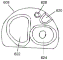
To secure the shuttle 512 relative to the elongate body 506, the leading end 508 may include a recess 514 in a sidewall of the leading end 508 for receiving the shuttle 512. Fig. 5B shows a perspective view of the front end 508 and the recess 514. The recess 514 may include a rear surface 516 and a front surface 518 configured to prevent axial movement of the shuttle 512 when the shuttle 512 is positioned in the recess 514. Further, leading end 508 may include a window 520 extending between a front surface 518 of recess 514 and a distal end of leading end 508, such that snare 504 may extend through window 520 when shuttle 512 is positioned in recess 514. The window 520 may also open into the side of the leading end 508, which may allow the snare to enter and exit the window 520 through the side of the leading end 508 when the shuttle 512 is inserted into or removed from the recess 514.
Also shown in fig. 5B are a first lumen 522 and a second lumen 524 extending through the leading end 508 and the elongate body 506. A first end of snare 504 may extend through first lumen 522, where it is operably connected to a controller not shown. The controller may advance and retract the first snare 504 to control the size of the snare loop assembly 502, as described in more detail above. Since the suture loop (not shown) is coupled to snare 504 by retention member 512, movement of the first end of snare 504 may move portions of the suture loop and retention member 512 into or out of first lumen 522. Additionally, in variations in which the suture loop is sized to have a certain amount of excess suture (as will be described in more detail below), some or all of such excess suture may remain or otherwise be maintained in the first lumen 522. When the suture loop includes a suture knot (not shown), the suture knot and the tail of the suture loop may be positioned in and/or extend through the second lumen 524.
The snare loop assembly 520 may also include a locking wire 526 for securing the shuttle 512 relative to the leading end 508 when the shuttle 512 is positioned in the recess 514. Specifically, the leading end 508 may include a locking wire lumen 528 that extends through the elongate body 506 and into the recess 514 such that the locking wire 526 may be advanced through the locking wire lumen 528 and into the recess 514. The shuttle 512 can include a locking lumen 530 extending therethrough, and the shuttle 512 can be configured such that the locking lumen 530 is aligned with the locking wire lumen 528 when the shuttle 512 is positioned in the recess 514. When the shuttle 512 is positioned in the recess 514 to align the locking lumen 530 with the locking wire lumen 528, the locking wire 526 may be advanced from the locking wire lumen 528 through the locking lumen 530 of the shuttle 512 (which in some variations may be further advanced through a second portion of the locking wire lumen 528 on the opposite side of the recess 514). Engagement between locking wire 526, leading end 508, and shuttle 512 may hold shuttle 512 in place in recess 514, thereby securing shuttle 512 (and therewith, second end 510 of snare 504) relative to leading end 508. To release the fixed second end 510 of snare 504, locking wire 526 may be retracted into locking wire lumen 528 to disengage locking wire 526 from shuttle 512.
Depending on the relative shapes of the shuttle and the recess of the leading end, rotation of the second end of the snare may have a tendency to rotate the shuttle relative to the leading end of the elongate body. Thus, in some variations, the snare may be configured to help minimize rotation of the shuttle (and thus the fixed end of the snare) relative to the elongate body. For example, fig. 6A-6H illustrate one such variation of a closure device 600 having a snare loop assembly 602 including a releasable snare 604. In particular, fig. 6A and 6B illustrate perspective views of the distal portion of the closure device 600. As shown, the closure device 600 may include an elongated body 606 and a leading end 608. Snare loop assembly 602 may include a snare, a suture loop, and a retaining member releasably connecting the snare to the suture loop, although only snare 604 is shown in fig. 6A and 6B. Snare 604 may have a first end (not shown) connected to one or more portions of a control (not shown) and a second end 610 connected to a shuttle 612. The shuttle 612 may be configured to secure the second end 610 of the snare 604 to the elongate body 606, and the first end of the snare 604 may be advanced or withdrawn, e.g., via a control, to open or close the snare 604 and snare loop assembly 602.
The leading end 608 may include a recess 614 for receiving the shuttle 612, as described in more detail above. In particular, the shuttle 612 may be positioned in the recess 614, as shown in fig. 6A, and may be temporarily fixed in position relative to the leading end 608 to lock the second end 610 of the snare 604 in place relative to the elongate body 604. To release the snare 604, the shuttle 612 may be disengaged from the leading end 608, as shown in fig. 6B. In some cases, shuttle 612 may be sized and shaped such that an outer surface of shuttle 612 matches a contour of a sidewall of leading end 608 when shuttle 612 is placed in recess 614. By matching the contour of the shuttle 612 to the sidewalls of the leading end 608, the shuttle 612 and leading end 608 may reduce the likelihood of damaging tissue during advancement of the closure device 600.
Fig. 6C and 6D show a top view and a front view, respectively, of the front end 608 of the closure device. As shown, the recess 614 may include a rear surface 616 and a front surface 618, which may be configured to prevent axial movement of the shuttle 612 relative to the recess 614. The front end 608 may also include a window 620 that extends between the front surface 618 and a distal end of the front end 608 and opens into a side of the front end 608. When shuttle 612 is positioned within recess 614, such as shown in fig. 6A, snare 604 may extend out of the distal end of leading end 608 through window 620. Also shown in fig. 6D are a first lumen 622 and a second lumen 624. The first end of snare 604 may extend through a first lumen 622, such as described in more detail above. Similarly, the suture knot and the tail of the suture loop may be positioned in and/or extend through the second lumen 624, as described in more detail above.
The snare loop assembly 620 may also include a locking wire 626 for securing the shuttle 612 relative to the leading end 608 when the shuttle 612 is positioned in the recess 614. Specifically, the leading end 608 can include a locking wire lumen 628 that extends through the elongate body 606 and into the recess 614 such that the locking wire 626 can be advanced through the locking wire lumen 628 and into the recess 614. Fig. 6E-6H illustrate top, side, front, and back views, respectively, of the shuttle 612 of fig. 6A and 6B. As shown, the shuttle 612 can include a locking lumen 630 extending therethrough, and the locking lumen 630 can be aligned with the locking wire lumen 628 when the shuttle 612 is positioned in the recess 614. When shuttle 612 is positioned in recess 614, locking wire 626 can be advanced from locking wire lumen 628 through locking lumen 630 of shuttle 612 (which in some variations can be further advanced through a second portion of locking wire lumen 628 on the opposite side of recess 614). The engagement between the locking wire 626, the shuttle 612, and the locking wire lumen 628 may prevent the shuttle 612 from exiting the recess 614, thereby securing the shuttle 612 relative to the leading end 608 and therewith the second end 610 of the snare 604. To release the fixed second end 610 of the snare 604, the locking wire 626 may be retracted into the locking wire lumen 628 to disengage the locking wire 626 from the shuttle 612. Snare 604 is not shown in fig. 6G and 6H. In contrast, fig. 6G and 6H illustrate snare lumen 632 in shuttle 612, into which snare 604 may be placed and secured (e.g., by one or more adhesives, welding, mechanical connection, etc.).
As mentioned above, shuttle 612 may be configured to help minimize rotation of shuttle 612 relative to recess 614. Specifically, in the variation of the closure device 600 shown in fig. 6A-6H, the shuttle 612 may include a channel 634 and the recess 614 may include a protrusion 636 configured to be positioned in and engage the channel 634 of the shuttle 612 when the shuttle 612 is positioned in the recess 614 of the leading end 608. The engagement between the protrusion 636 and the channel 634 of the shuttle 612 may prevent rotation of the shuttle 612 relative to the leading end 608.
In other variations, shuttle 612 may include one or more protrusions that may engage recesses within leading end 608. For example, fig. 7A-7J illustrate variations of one such embodiment of a closure device 700. The closure device 700 may have some features in common with the variations of the closure device 600 shown in fig. 6A-6H, which common features will not be described in detail. FIG. 7A shows a perspective view of a distal portion of a closure device 700 including a leading end 708, a shuttle 712, and a locking wire 726. Fig. 7B-7D show perspective, front, and top views, respectively, of the front end 708. As shown, the front end 708 may include a recess 714 having a rear surface 716 and a front surface 718, a first lumen 722 and a second lumen 724, a bore 720 extending between the front surface 718 and a distal end of the front end 708, and a locking wire lumen 728. Also shown is a track 742 that is further disposed in the recess 714.
Fig. 7E-7I show a top perspective view, a bottom perspective view, a front view, a top view, and a side view, respectively, of the shuttle 712. As shown, shuttle 712 includes a locking lumen 730 and a snare lumen 732. Shuttle 712 may also include a protrusion 744 that may extend from a bottom surface of shuttle 712. When shuttle 712 is positioned within recess 714, projection 744 can be configured to fit at least partially within and engage track 742 of leading end 708. This engagement between the protrusion 704 and the track 702 may prevent rotation between the shuttle 712 and the leading end 708. In the variation of shuttle 612 shown in fig. 7E-7I, projection 744 can include an inclined portion 746. When the shuttle 712 is released from the leading end 708 (e.g., by withdrawing the locking wire 728, as described in more detail above), the ramped portion 706 may facilitate the ramped portion 706 to slide out of the track 702 more easily, which may reduce the likelihood of the shuttle 712 becoming stuck in the recess 714.
When the variations of the releasable snares described herein are secured in place by the use of locking threads, it may be desirable to reduce the likelihood that the locking threads may prematurely withdraw from the shuttle to release the secured end of the snare. For example, bending or twisting of the elongated body may provide one or more pulling forces to the locking wire. In these variations, it may be desirable to increase the force required to pull the locking wire from the shuttle. For example, in some variations, one or more adhesives may be used to temporarily couple the locking wire to or shuttle (e.g., to a locking lumen therein) and/or the elongate body (e.g., to a locking wire lumen therein). In these cases, the adhesion provided by the adhesive may prevent the locking wire from being withdrawn from the shuttle, such that incidental forces applied to the locking wire may not be sufficient to cause the locking wire to release prematurely. To release the shuttle from the elongate body, the force applied to the locking wire (e.g., via a controller, as will be discussed in more detail below) will need to be large enough to break the connection between the locking wire and the adhesive.
In other variations, the shape of the locking wire may increase the force required to withdraw the locking wire from the suture. In some variations, the locking wire may include one or more bends or coils that resist movement relative to the shuttle and/or elongate body. For example, in the variation of the closure device 700 shown in fig. 7A-7J, the locking wire 726 may include a bend 750, which may be configured to engage a portion of the shuttle 712. Specifically, shuttle 712 may include a window 752 extending from locking lumen 730 to an exterior of shuttle 712. When the locking wire 726 is positioned to lock the shuttle 712 in place relative to the front end 708, the curved portion 750 of the locking wire 726 may be positioned to extend at least partially into the window 752 of the shuttle 712. For example, as shown in fig. 7J, the locking wire 726 can extend from a first portion of the locking wire lumen 728 proximal of the shuttle 712, through the locking lumen 730, and into a second portion of the locking wire lumen 728 distal of the shuttle 712 to lock the shuttle 712 relative to the front end 708. When the bend 750 of the lock wire 726 extends at least partially into the window 752 of the shuttle 712 (as shown in fig. 7J), the bend 750 may resist proximal movement of the lock wire 728 relative to the shuttle 712. This resistance may prevent the latch wire 726 from being accidentally released from the shuttle 712. To release the locking wire 726, a user may apply a proximal force sufficient to straighten the bend 752, e.g., via a control, so that it may enter and pass through the locking lumen 750. Although the bend 752 is shown in fig. 7J as being positioned in the shuttle 712, in other instances, the bend 752 may be positioned between the shuttle 712 and the locking wire lumen 728, either at the proximal or distal end of the shuttle 712, such that the bend 752 resists being pulled into the locking lumen 730 and/or the locking wire lumen 728 of the shuttle 712. Further, although shown in fig. 7J as including a bend 752, the locking wire 726 may additionally or alternatively include a coil that may resist being pulled through the locking lumen 730 and/or the locking wire lumen 728 of the shuttle 712, as discussed immediately above.
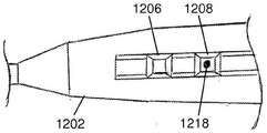
When the closure device comprises a snare (which is temporarily secured to the elongate body via a shuttle and locking wire), the locking wire may be withdrawn in any suitable manner. For example, fig. 8A-8F illustrate a variation of the handle assembly 800 configured to release the fixed end of the snare (not shown) by withdrawing the locking wire. Fig. 8A shows a perspective view of handle assembly 800. As shown, the handle assembly 800 may include a handle body 802, a snare control 804, a suture control 806, and a snare release 808. In these variations, the first end of the snare is operably connected to the snare control 804, and the second end of the snare may be secured to the leading end of the elongate body by a shuttle and locking wire, as described above. Snare control 804 may advance and retract along track 805 to advance and retract the first end of the snare relative to the elongate body. Advancement and retraction of the first end of the snare may open and close the snare loop assembly, respectively. The suture control 806 may be connected to a tail 810 of a suture loop (not shown). The suture control 806 may be pulled to tighten the suture loop. Specifically, as the tail 810 of the suture loop is withdrawn, the suture of the suture loop may be pulled through the suture knot of the suture loop to reduce the size of the suture loop. Similarly, snare release 808 is operably connected to the locking wire 812, and may be pulled or otherwise manipulated to pull the locking wire 812 proximally relative to the elongate body (and thereby release the fixed ends of the shuttle and snare from the elongate body).
In some variations, the handle assembly 800 may be configured to minimize the likelihood that the fixed end of the snare is prematurely released. For example, in the variation of the handle assembly 800 shown in fig. 8A-8E, the suture control 806 may be configured to at least temporarily obscure the access snare release 808. For example, fig. 8B shows a perspective view of a suture control 806. As shown, the suture control 806 can include a suture attachment portion 814, a grip 816, and a chamber 818 disposed within the grip 816. The suture connecting portion 814 of the suture control 806 may be attached to the tail 810 of the suture loop, and the suture connecting portion 814 may be positioned in the first opening 820 of the handle body 802 to temporarily couple the suture control 806 to the handle body 802, such as shown in fig. 8C. Similarly, the snare release 808 may be attached to the locking wire 812 and may be positioned at least partially into the second opening 822 of the handle body 802 to temporarily couple the snare release 808 to the handle body 802, such as shown in fig. 8C. When the suture control 806 and snare release 808 are positioned partially in the first opening 820 and the second opening 822, the portion of the snare release 808 extending out of the handle body 802 may be positioned within the chamber 818 of the suture control 806. Thus, the suture control 806 may temporarily obscure the snare release 808 and may prevent a user from accessing the snare release 808 while the suture control 806 is in place. To access the snare release 808, the suture control 806 may first be disengaged from the handle body 802 and pulled proximally to expose the snare release 808, as shown in fig. 8D. Snare release 808 may then be pulled proximally relative to the handle body 802 to pull the locking wire 812, as shown in fig. 8E. This withdrawal of the locking wire 812 may release the fixed end of the snare, as described in more detail above.
In some variations, when the snare release 808 is withdrawn, the snare release 808 may be configured to control the distance that the snare release 808 may be pulled. For example, fig. 8F shows an enlarged view of a variation of snare release 808. As shown, the snare release 808 may have a main body 824 and first and second stops 826, 828 attached to the main body 824. Each of the first and second stops 826, 828 may include one or more clips 830 extending from a respective arm 832. The arms 832 may in turn be connected to the body 824. for example, in the variation shown in fig. 8F, each stop includes first and second arms, each having a catch. The first stop 826 may further include a grip 834 attached to the arm 832 of the first stop 826. When snare release 808 is initially positioned in second opening 822, the catch 830 of first stop 826 may engage housing body 802 to hold snare release 808 in the first position (as shown in fig. 8D). When so positioned, the clip 830 of the first stop 826 may prevent withdrawal of the snare release 808. Before the snare release 808 may be withdrawn, a user may apply pressure to the grip 834 to deflect the arm 832 of the first stop 826 and the clip 830 toward the body 824 of the snare release 808, which may allow the clip 830 to disengage from the housing body 802 and pass through the second opening 822 of the control body 802. With the clip 830 of the first stop 826 disengaged from the housing body 802, the snare release 808 may be pulled proximally until the clip 830 of the second stop 828 engages the housing body 802, placing the snare release 808 in the second position, as shown in FIG. 8E. The distance between the first and second stops 826, 828 (i.e., the distance between the first and second positions) of the catches 830 may be sized to limit movement between the first and second stops 826, 828.
Fig. 13A-13C illustrate another variation of the handle assembly 1300 configured to release the locking wire from the fixed end of the snare. In particular, fig. 13A and 13B show perspective views of a handle assembly 1300. As shown, the handle assembly 1300 may include a handle body 1301, a snare control 1302, a suture control 1304, and a snare release button 1308. A snare control 1302 may be attached to a first end of the snare and may be moved along a track 1303 to open and close the snare loop assembly. The locking wire 1314 may be used to secure the second end of the snare (not shown), as described in more detail above, and may be released by using the snare release button 1308. The suture control 1304 may be attached to the tail 1306 of the suture loop (not shown) and may be withdrawn relative to the handle body 1301 to tighten the suture loop. The suture control 1304 may also be used to actuate a snare release button 1308, as will be described in more detail below.
The snare release button 1308 may be attached to or otherwise positioned relative to the locking wire 1314 such that when the snare release button 1308 is depressed, the snare release button 1308 pulls the locking wire 1314 proximally relative to the elongate body 1316 (e.g., disengages the locking wire 1314 from a shuttle (not shown)). In some variations, such as shown in fig. 13A-13C, the snare release button 1308 may be configured to reduce the likelihood that the snare release button 1308 is inadvertently depressed. For example, the snare release button 1308 may be configured such that it does not extend from the outer surface of the handle body 1301. Further, the snare release button 1308 may be sized so that it is too small to be depressed by a normal adult's finger. For example, in some variations, the snare release button 1308 may have a diameter less than or equal to about 0.20 inches. In some variations, the snare release button 1308 may have an elliptical cross-section that includes a major axis of about 0.20 inches and a minor axis of about 0.18 inches. In some variations, the handle assembly 1300 may be configured such that the suture control 1304 may actuate the snare release button 1308. In particular, the suture control 1304 may include a grip 1312 and a fork 1310 extending therefrom. The tail 1306 of the suture may be attached to a fork 1310 such as described above with respect to suture control 806 of fig. 8A-8F, and may be used to tighten the suture loop. The suture may be disengaged from the suture control 1304 and the prong 1310 may be sized such that it may be used to depress the snare release button 1308, such as shown in the cross-sectional side view of fig. 13C. When suture control 1304 is used to press snare release button 1308 to release the snare, the user may be forced to release the suture loop from the snare loop assembly prior to releasing the snare.
The snare release button may be configured to pull the locking wire proximally relative to the elongate body in a variety of ways. In some embodiments, the locking wire may be attached to a fixed portion of the handle body, an example of which is shown in fig. 17A and 17B, while in other embodiments, the locking wire may be connected to a member configured to move relative to the handle body, an example of which is shown in fig. 18A and 18B. Connecting the locking wire to the fixed portion of the handle body may reduce the amount of the snare release button that needs to be depressed to disengage the locking wire, as described in more detail below. Conversely, connecting the locking wire to the moveable member may reduce the force that a user needs to apply to the suture button to disengage the locking wire.
Fig. 17A and 17B illustrate cross-sectional top views of variations of the handle assembly 1700, such as discussed above with respect to fig. 13A-13C. As shown, the handle assembly 1700 may include a handle body 1701 and a snare release button 1702. The snare release button 1702 is movably positioned within a button housing 1718, which in turn may be connected to the interior of the handle body 1701. The button housing 1718 may be integrally formed with the handle body 1701, or it may be separately formed from the handle body 1701 and attached thereto, e.g., by one or more adhesives, bonding, mechanical attachment, etc. Generally, the button housing 1718 slidably receives the snare release button 1702 such that insertion of a portion of a suture control (e.g., the fork 1710 of the suture control 1704 as shown in fig. 17B) into the handle body 1701 may cause the snare release button 1702 to move relative to the button housing 1718. For example, in some variations, the button housing 1718 may include a track or lumen, e.g., a button track 1713 as shown in fig. 17A and 17B, which may constrain the movement of the snare release button 1702. In some such variations, the button housing 1718 may constrain movement of the snare release button 1702 in a linear direction, which may be perpendicular to the longitudinal axis of the handle body 1701, in some cases, such as through the button track 1713. Additionally, in some cases, the snare release button 1702 may be configured such that it may be prevented from exiting the handle body 1701. In some variations, such as shown in fig. 17A and 17B, the snare release button 1702 may have a shaft 1716 and a head 1708. In some such variations, the stem 1716 is slidably positioned in the button housing 1718, while the head 1708 may be sized such that it is prevented from entering the housing button 1718. In other variations, the stem 1716 may be sized to extend at least partially through the opening 1711 in the handle body 1701, while the head 1708 may be sized such that it may be prevented from passing through the opening 1711 in the handle body 1701.
Also shown in fig. 17A and 17B is a lock line 1714 (which can be any of the lock lines described in more detail above). The snare release button 1702 may include a lumen 1726 extending therethrough (e.g., through the shaft 1716 or another portion of the snare release button 1702). The locking wire 1714 may be positioned to extend through the lumen 1726 of the snare release button 1702 and at least a portion of the button housing 1718. For example, the button housing 1718 can include a lock wire track 1720 extending at least partially therethrough, and the lock wire 1714 can be positioned to extend at least partially through the lock wire track 1720. Although the button housing 1718 is shown with the locking wire track 1720 and the button track 1713 exposed, it should be understood that the button housing 1718 may include a cover or may be otherwise configured to enclose some or all of the locking wire track 1720 and the button track 1713.
Further, in the variation shown in fig. 17A and 17B, the proximal end of the locking wire 1714 may be attached to a fixed portion of the handle assembly 1700. In these variations, the proximal end of the locking wire 1714 may be connected to any portion of the handle assembly 1700 that is fixed relative to the handle body 1701. In some such variations, the locking wire 1714 may be directly connected to the handle body 1701. In other such variations, such as shown in fig. 17A and 17B, a locking wire 1714 may be connected to a portion of the button housing 1718. The proximal end of the locking wire 1714 may be connected to the handle assembly 1700 in any suitable manner (e.g., by adhesive, welding, soldering, mechanical connection using hooks, bolts, screws, etc.). For example, in some variations, an adhesive may fill a portion of the locking wire lumen 1720 to secure the proximal end of the locking wire 1714 to the button housing 1718.
The snare release button 1702 may be actuated from an initial position (as shown in fig. 17A) to a depressed position (as shown in fig. 17B), which may disengage the locking wire 1714 from the shuttle to release the fixed end of the snare, as discussed in more detail above. In some cases, as shown in fig. 17A and 17B, a force may be applied to the snare release button 1702 by inserting the prongs 1710 of the suture control 1704 through the opening 1711 of the handle body 1701. However, it should be understood that other structures may also be inserted into the opening 1711 to apply a force to the snare release button 1702 to depress it. As the snare release button 1702 is moved into the depressed configuration, the snare release button 1702 may pull the locking wire 1714 into the button housing 1718. For example, when the snare release button 1702 is in the initial position shown in fig. 17A, the lumen 1726 of the snare release button 1702 may be aligned with the locking wire lumen 1720. As the snare release button 1702 is depressed, the lumen 1726 of the snare release button 1702 and a portion of the locking wire 1714 may be pushed out of alignment with the locking wire lumen 1720, which may pull a length of the locking wire 1714 into the button housing 1718. This, in turn, can pull the distal end of the locking wire 1714 to disengage it from the shuttle, as discussed in more detail above. In addition, because the locking wire 1714 is pushed out of alignment with the locking wire lumen 1720 on both sides of the snare release button 1702 as the snare release button 1702 is depressed, the distal portion of the locking wire 1714 may be pulled proximally a distance greater than the distance the snare release button 1702 moves. In some cases, the snare release button 1702 may be pulled proximally twice as far as the snare release button 1702 is moved.
Fig. 18A and 18B illustrate another embodiment of a handle assembly 1800 having a snare release button 1802. As shown, the snare release button 1802 is movably positioned within a button housing 1808, which in turn may be attached to the interior of the handle body 1801. The button housing 1808 may be integrally formed with the handle body 1801, or it may be separately formed from the handle body 1801 and attached thereto, e.g., by one or more adhesives, bonding, mechanical connection, etc. As discussed above with respect to fig. 17A and 17B, button housing 1808 slidably receives snare release button 1802 such that insertion of a portion of a suture control (e.g., prongs 1810 of suture control 1804 as shown in fig. 18B) into opening 1811 of handle body 1801 may cause snare release button 1802 to move relative to button housing 1808. For example, the button housing 1808 may include a button track 1816 that may constrain the movement of the snare release button 1802, as described above. In some variations, the button tracks 1816 may constrain the snare release button 1802 from movement in a direction perpendicular to the longitudinal axis of the handle body 1801. Button housing 1808 may also include a locking wire track 1818 through which locking wire 1814 may enter button housing 1808. The housing may also include a cover, not shown, or may be otherwise configured to enclose some or all of the locking wire track 1818 and the button track 1816, but is not required. In some variations, as shown in fig. 18A and 18B, the snare release button 1802 may include a stem 1820 and a head 1822. In some variations, the stem 1820 can be sized to fit at least partially through the opening 1811 of the handle body 1801 (as shown in fig. 18A), while the head 1808 can be sized such that it can be prevented from passing through the opening 1811 of the handle body 1801. This may prevent the snare release button 1802 from exiting the handle body 1801.
In the variation shown in fig. 18A and 18B, the proximal end of the locking wire 1814 may be connected to the snare release button 1802. Specifically, the lock wire 1814 may enter the button housing 1808 through the lock wire track 1818 and connect to the snare release button 1802. The locking wire 1814 may be connected to the snare release button 1802 in any suitable manner (e.g., by adhesive, welding, soldering, mechanical connection, etc.). For example, in the variation shown in fig. 18A and 18B, locking wire 1814 may include a post 1806 (such as a screw, etc.), and locking wire 1814 may be rolled around the post to secure locking wire 1814 thereto. In some variations, a portion of the locking wire 1814 may be held between a portion of the post 1806 and the snare release button 1802. Additionally or alternatively, adhesive may also be applied to the locking lines 1814 to help secure the locking lines 1814 to the post 1806.
The snare release button 1802 may be actuated to disengage the distal portion of the locking wire 1814 from the shuttle to release the fixed end of the snare, as discussed in more detail above. Specifically, a force may be applied to the snare release button 1802 to move the snare release button 1802 from an initial position (as shown in fig. 18A) to a depressed position (as shown in fig. 18B). In some cases, as shown in fig. 18A and 18B, a force may be applied to the snare release button 1802 by inserting a portion of the suture control 1804 (e.g., the prongs 1810 of the suture control 1804) through the opening 1811 of the handle body 1801. However, it should be understood that other structures may also be inserted into the opening 1811 to apply a force to the snare release button 1802 to depress it. As the snare release button 1802 is moved along the button track 1816, the snare release button 1802 may pull a portion of the locking wire 1814 into the button track 1816, which in turn may pull a portion of the locking wire 1814 into the button housing 1808. As the proximal portion of the locking wire 1814 is pulled by the snare release button 1802, the distal portion of the locking wire 1814 may also be pulled proximally along the elongated body of the closure device, which in turn may disengage the locking wire 1814 from the shuttle. In these variations, connecting the proximal end of the locking wire 1814 to the snare release button 1802 may reduce the force required to move the snare release button 1802 (e.g., by removing resistance that may occur when the proximal end of the locking wire 1814 is attached to a fixed portion of the handle body 1801).
In some variations, it may be desirable to configure and position the locking wire of the closure device to have a certain amount of slack within the handle assembly and/or elongated body. For example, when the closure device described herein is heated (e.g., during sterilization), the elongated body may increase in length relative to the locking wire. For example, in the variation of the handle assembly 1300 shown in FIGS. 13A-13C, the locking wire 1314 may be configured to have some slack 1318 in the handle body 1301. Expansion of the elongate body 1316 may cause slack 1318 of the locking wire 1314 to be taken up rather than the locking wire 1314 being pulled from the shuttle. Without slack in the locking wire 1314, expansion of the elongate body may withdraw the locking wire from the shuttle and prematurely release the snare. The locking wire 1314 may be configured with any suitable amount of slack 1318 (e.g., at least about 2mm, at least about 5mm, etc.). Snare release (such as snare release button 1308 shown in fig. 13A-13C) may also pull on the locking wire to remove slack when snare release is used to withdraw the locking wire relative to the elongate body.
Although the releasable snare described above is configured to release the fixed end of the snare, other variations of the releasable snare described herein may also be configured to release the snare along the length of the snare. For example, fig. 9 shows a variation of snare loop assembly 900 with releasable snare 902. Also shown in fig. 9 is a suture loop 904 and a retaining member 906 coupling the suture loop 904 to the snare 902, as described throughout. The releasable snare 902 may have a proximal end 908 and a distal end 910 that may be temporarily connected to each other. Specifically, the proximal end 908 of the snare may have a first end not shown and a second end 912, and the distal end 910 of the snare 902 may have a first end 914 and a second end 916. The second end 916 of the distal portion 910 may be fixed relative to an elongated body (not shown) of the closure device, while the first end 914 of the distal portion 910 is releasably connected to the second end 912 of the proximal portion. A first end of proximal portion 908 is operably connected to a snare control, which may be manipulated to advance or retract snare 902 relative to the elongate body to open and close snare loop assembly 900, as described above. To release the snare 900, the second end 912 of the proximal portion 908 of the snare 902 may be disengaged from the first end 914 of the distal portion 910 to release the distal portion 910.
The proximal end 908 and distal end 910 of snare 902 may be releasably connected in any suitable manner. Fig. 10A and 10B show a first such variation of a releasable snare 1000. As shown in FIG. 10A, snare 1000 may include a distal end 1002 releasably connected to a proximal end 1004. The distal end 1002 may have a first junction 1006 connected to a first end 1008 of the distal end 1002 of the snare 1000, and the proximal end 1004 may include a second junction 1010 connected to a second end 1012 of the proximal end 1004 of the snare 1000. Typically, the first and second joints 1006, 1010 are configured to temporarily engage one another such that the first and second joints 1006, 1010 are axially fixed along the longitudinal axis of the snare 1000, but may be configured such that radial movement between the first and second joints 1006, 1010 may cause disengagement of the first and second joints 1006, 1010. Snare 1000 may further include a constraining sheath 1013 in order to maintain first and second junctions 1006, 1010 in an axially fixed configuration. When first and second junctions 1006, 1010 are joined to axially secure the junctions, constraining sheath 1013 may be positioned around first and second junctions 1006, 1010, as shown in fig. 10A. Constraining sheath 1013 may radially constrain first joint 1006 and second joint 1010 and may thereby prevent first joint 1006 and second joint 1010 from being radially disengaged. To release the snared distal end 1002, the constraining sheath 1013 can be withdrawn to expose the first junction 1006 and the second junction 1010, as shown in fig. 10B. The exposed junction may then be disengaged to release the distal end 1002 of the snare 1000 relative to the proximal end 1004 of the snare 1000.
First and second engaging portions 1006, 1010 may be any suitable structure that may engage and disengage each other in a radial direction and may be axially fixed when engaged. For example, in the variation of snare 1000 shown in fig. 10A and 10B, the first and second junctions 1006, 1010 may comprise hooks 1014 having a corresponding shape, each comprising a lip 1016. The hooks 1014 of the first and second joints 1006, 1010 may be positioned such that the lips 1016 of the hooks 1014 catch on each other (as shown in fig. 10B) to prevent the first and second joints 1006, 1010 from being pulled apart in an axial direction.
Fig. 11A and 11B illustrate a second variation of a releasable snare 1100. As shown, the snare 1100 may include a distal portion 1102 and a proximal portion 1104, wherein the distal portion 1102 includes a first joint 1106 attached to a first end 1108 of the distal portion 1102 and the proximal portion 1104 includes a second joint 1110 attached to a second end 1112 of the proximal portion 1104. Snare 1100 may also include a restraining sheath 1113, as described above. In these variations, first interface 1106 may include plug 1114 and second interface 1110 may include a partially hollow cup 1116 configured to at least partially receive plug 1114. To axially secure the first and second interfaces 1106, 1108, the plug 1114 may be positioned at least partially within the cup 1116 and the constraining sheath 1113 may be placed around the plug 1114 and the cup 1116, as shown in FIG. 11A, to prevent the plug 1114 and the cup 1116 from disengaging. In addition, the cup 1116 may include a distal lip 1118 that may prevent the plug 1114 from being pulled axially away from the cup 1116 (e.g., along the longitudinal axis of the snare 1100). As described above, the constraining sheath 1113 may be withdrawn to expose the first and second junctions 1106, 1108, as shown in fig. 11B, so that the plug 1114 may disengage the cup 1116 to release the distal end 1102 of the snare 1100 from the proximal end 1104 of the snare 1102. While the first engagement formation 1106 is shown in fig. 11A and 11B as having a plug 1114 and the second engagement formation 1108 is shown as having a cup 1116, it will be appreciated that in other variations the first engagement formation 1106 may comprise a cup 1116 and the second engagement formation 1108 may comprise a plug 1114.
When the snare loop assembly comprises a releasable snare having a distal end releasably connected to a proximal end of the snare and a restraining sheath maintaining the connection between the distal end and the proximal end, the snare may be moved and released in any suitable manner. For example, when the proximal and distal ends of the snare are coupled, advancement and retraction of the proximal end of the snare may in turn advance and retract the distal end of the snare to open and close the snare loop assembly. It may also be necessary to move the restraining sheath with the snare as the proximal and distal portions of the snare are advanced and retracted to maintain engagement between the proximal and distal portions of the snare. For example, fig. 12A-12D illustrate one such embodiment of a handle assembly 1200 for actuating the snare and releasing the distal end of the snare from the proximal end of the snare. Specifically, fig. 12A shows a top view of a handle assembly 1200 including a handle body 1202 and a snare control 1204. The snare control 1204 may be advanced or withdrawn to advance and withdraw the snare, respectively.
FIG. 12D shows a cross-sectional side view of a portion of the handle body 1202. As shown, the snare control 1202 may include a first control 1206 and a second control 1208. The first controller 1206 may be connected to the proximal end 1209 of the snare 1210, while the second controller 1208 may be connected to the restraining sheath 1212. The first and second controllers 1206, 1208 may be moved independently or in combination along the track 1214 to move the proximal end 1209 of the snare 1210 and the restraining sheath 1212, respectively. As the first and second controllers 1206, 1208 are moved together along the track 1214, the position of the proximal end 1209 of the snare 1210 relative to the restraining sheath 1212 may be maintained (e.g., so that the restraining sheath 1212 continues to hold the proximal end 1209 and distal end (not shown) of the snare 1210 in connection). Conversely, relative movement between the first and second controllers 1206, 1208 may move the restraining sheath 1212 relative to the proximal end 1209 of the snare 1210, which may be used to release the distal end (not shown) of the snare 1210.
For example, the closure device may be initially configured such that the proximal and distal ends 1209, 1212 of the snare 1210 are coupled and held in engagement by the restraining sheath 1212. To manipulate the snare loop assembly of the closure device, the first controller 1206 and the second controller 1208 may be moved together to advance and retract the snare 1210, thereby opening and closing the snare loop assembly. In some variations, the snare control 1202 includes a mechanism to move the first control 1206 and the second control 1208 together. For example, as shown in fig. 12B, the snare control 1200 may include a cap 1216, which may be configured to temporarily couple the first control 1206 to the second control 1208. Specifically, the cover 1216 may enclose a portion of each of the first and second controls 1206 and 1208 such that a user may advance or retract the cover 1216 to advance or retract the first and second controls 1206 and 1208, respectively. In some variations, the cover 1216 may include a magnet (not shown) that may magnetically attract and engage the magnet 1218 of the first controller 1206 and/or the second controller 1208 to hold the cover 1216 in place relative to the first controller 1206 and the second controller 1208, as shown in fig. 12A. While only the second controller 1208 is shown in fig. 12B as having a magnet 1218, it should be understood that in some variations only the first controller 1206 may include a magnet, and in other variations both the first controller 1206 and the second controller 1208 may include a magnet 1218.
To release the distal end of the snare, the cover 1216 may be disengaged from the first and second controls 1206 and 1208 to expose the first and second controls 1206 and 1208, as shown in fig. 12B. The second controller 1208 may be proximally withdrawn relative to the first controller 1206, as shown in fig. 12C, to withdraw the restraining sheath 1212 relative to the proximal end 1209 of the snare 1210. Withdrawal of the constraining sheath 1212 may expose the junction of the proximal and distal snare portions, allowing the junction of the proximal and distal portions to disengage.
Tightening device
When the closure devices described above are used to place and tighten a suture loop around tissue, it may be desirable to manage the tension applied to the suture as the suture loop is tightened. Accordingly, the closure devices described herein may include one or more tightening devices or mechanisms for managing the tension applied to a portion of the suture loop (e.g., the tail of the suture loop) of the closure device. In some instances, it may be desirable to limit the maximum tension that may be applied to the suture loop at different times during tightening. For example, if sufficient tension is applied to the suture loop, the suture loop may cut through, break or otherwise damage the enclosed tissue and/or may damage or destroy one or more components of the closure device. In some variations, the described closure devices may be configured to limit the tension applied to the suture loop during tightening of the suture loop. For example, in variations where the suture is connected to a suture control, the suture control can be configured to disengage the suture to limit the tension applied to the suture when a predetermined force (e.g., between about 8 pounds to about 10 pounds) is applied to the suture control.
In other instances, it may be desirable to facilitate the application of at least a minimum tension to the suture during tightening of the suture loop. For example, when the closure devices described herein are used to close a portion of the left atrial appendage (e.g., the neck of the left atrial appendage), it may be desirable to maximize closure of the left atrial appendage, which may reduce the likelihood that blood or other materials may enter or move out of the left atrial appendage through the ostium of the left atrial appendage. Thus, tightening the suture loop by applying at least a minimum predetermined tension to the suture may help to improve closure of the left atrial appendage, as will be described in more detail below. In some variations, the closure device may include one or more cinching devices that may facilitate applying at least a predetermined minimum tension to the suture during cinching. Further, applying another predetermined tension to the suture may cause the suture loop to release from the snare loop assembly. By allowing the user to apply one or more predetermined tensions, the tightening device may help reduce user variability from procedure to procedure, which may help improve repeatability of tightening among multiple procedures.
In other cases, the tightening device may be configured to facilitate applying at least a minimum predetermined tension to the suture loop without exceeding a maximum predetermined tension. Additionally or alternatively, the tightening device may be configured to facilitate the application of a plurality of predetermined tensions (or ranges of tensions). For example, in some variations (as will be described in greater detail below), the tightening device may have a first configuration in which the tightening device facilitates applying a first predetermined tension to the suture and a second configuration in which the tightening device facilitates applying a second predetermined tension to the suture. It may be desirable to enable a user to apply a first predetermined tension to the suture at a first point in time and a second predetermined tension to the suture at a second point in time, as will be described in more detail below. Examples of suitable tightening devices are described in U.S. patent application No. 13/490919, which is previously incorporated herein by reference.
Marking
As mentioned above, in some instances, it may be desirable to allow a user to determine whether the snare loop assembly has become twisted. For example, in some variations, the closure device may include one or more indicia that may have a first configuration when the snare loop assembly is twisted and a second configuration when the snare loop assembly is unwrapped. For example, fig. 15A and 15B illustrate the distal end of one such embodiment of a closure device 1500. As shown, the closure device 1500 may include an elongate body having a leading end 1502 and a snare loop assembly 1504 extending therefrom. Snare loop assembly 1504 may include a snare, a suture loop, and a retaining member, as described above, although only retaining member 1506 is shown in fig. 15A and 15B. In this variation, the closure device 1500 may include a first indicia 1508 and a second indicia 1510. These markers may be directly visible or may be indirectly visible (e.g., by fluoroscopy, X-ray, or ultrasound).
These markings may be configured to allow a user to determine whether the snare loop assembly 1504 is twisted relative to the front end 1502 of the elongate body. In particular, the first marker 1508 may be positioned on or in the front end 1502 and may be configured such that the first marker 1508 is asymmetric with respect to a longitudinal axis of the front end 1502. For example, the first indicia 1508 is shown as L-shaped in fig. 15A and 15B, although it should be understood that the first indicia 1508 may be any suitable non-symmetrical shape. The first indicia 1508 may allow a user to determine the orientation of the front end 1502. For example, the legs 1509 of the first marker 1508 may point in a first direction, e.g., to the left, when the front end 1502 is in a first rotational orientation, as shown in fig. 15A and 15B, and may point in an opposite direction when the front end 1502 is flipped. The second marker 1510 may be attached to the snare loop assembly 1504 and may also be configured such that the second marker 1510 is asymmetric with respect to the longitudinal axis of the leading end 1502. In the variation of the closure device 1500 shown in fig. 15A and 15B, the second indicia 1510 may extend along a section of the loop defined by the snare loop assembly 1504 (i.e., the second indicia 1510 may not completely circumscribe the loop). For example, the second indicia 1510 shown in fig. 15A may include a circular arc segment 1511. The circle segment 1511 may extend in a first direction relative to the first indicia 1508 when the snare loop assembly 1504 is unwrapped and in an opposite direction relative to the first indicia 1508 when the snare loop assembly 1505 is twisted. For example, the circle arc segments 1511 shown in fig. 15A and 15B may extend in a direction opposite the legs 1509 of the first indicia 1508 when the snare loop assembly 1504 is unwrapped (as shown in fig. 15A), and may extend in the same direction as the legs 1509 of the first indicia 1508 when the snare loop assembly 1504 is twisted (as shown in fig. 15B). Thus, a user may see the relative orientation between the first and second indicia 1508, 1510 to determine whether the snare loop assembly 1504 is twisted. Although the second indicia 1510 is shown in fig. 15A and 15B as being connected to the retaining member 1506 of the snare loop assembly 1504, the second indicia 1510 may be connected to any suitable portion of the snare loop assembly 1504 (e.g., a snare, a suture loop, and/or a retaining member).
Method
Methods for closing the left atrial appendage are also described herein. It should be understood that any of the above-described devices may be used in conjunction with one or more of the methods described herein or the methods described in U.S. patent application No. 13/490919, which is previously incorporated herein by reference. Generally, the methods described herein involve accessing the left atrial appendage. Once access has been achieved, a closure device (such as those described above) may be advanced to the left atrial appendage. In some variations, the closure device may be advanced and positioned with the aid of one or more guiding devices (e.g., magnetic alignment elements) and/or one or more stabilizing/positioning devices (e.g., inflatable members, etc.), such as described in U.S. patent application No. 13/490919, which is previously incorporated herein by reference. In some such variations, the relative orientation between a first marker on the leading end of the elongate body and a second marker on a portion of the snare loop assembly may be visualized to determine whether the snare loop assembly is twisted or untwisted, as described in more detail above. If the snare loop assembly is twisted, the closure device may be retracted or otherwise manipulated to assist in untwisting the snare loop assembly. The closure device may be used to encircle and close the left atrial appendage. The suture loops or other closure elements may be tightened and released from the closure device to hold the left atrial appendage in a closed configuration. One or more tightening devices may be used to tighten and/or release the suture loops. The closure device may be withdrawn and a portion of the suture may be severed. These steps will be described in more detail below. In addition, one or more portions of the closure device may become stuck or otherwise caught on tissue during advancement, manipulation, or other use of the closure device. In these cases, the method may further comprise releasing one or more portions of the snare loop assembly. When a portion of the snare is released, they may be released in any suitable manner, such as those described above.
As mentioned above, some variations of the methods described herein may include obtaining access to the left atrial appendage. In some variations, a method for closing a left atrial appendage includes accessing the left atrial appendage from inside the heart and outside the heart. To access the interior of the heart, vessels are commonly used. For example, access may be obtained through one or several different veins or arteries (jugular vein, femoral artery, carotid artery, etc.). In some variations, the heart is accessed on the inside using a standard Seldinger technique with a needle via a common femoral vein (e.g., the left femoral vein). The guidewire may then be advanced through the needle, followed by the introducer sheath. The guide wire may then be removed. In some variations, a guiding catheter sheath may be placed in place of the guiding sheath, or the initial sheath may be replaced with the guiding catheter sheath.
Using fluoroscopy, angiography through the sheath, a catheter placed through the sheath, a guiding catheter sheath, or any combination thereof may be performed to view anatomical features and considerations of the access path for purposes of puncturing into the left atrium (e.g., tortuosity, clot, devices such as luminal venous filters, etc.). Fluoroscopy, ultrasound, intraluminal ultrasound, extra-cardiac echocardiography, esophageal echocardiography, or a combination thereof may be used to help visualize the penetration into the left atrium, and access to the left atrium may be obtained using standard penetration access techniques.
To access the heart from outside, a sub-thoracic (subloracic) access point may be used. The access point is typically determined based on the anatomical features of the patient. In some variations, the access point may be any suitable location (e.g., via sternum, thoracic lumen, or intercostal access to the chest, to the right of the xiphoid process, and pointing to the left shoulder of the patient, or in the costal cartilage or xiphoid process itself). Once the access point has been determined, a needle (e.g., a 17G Tuohy needle) may be advanced under fluoroscopic guidance using standard pericardial puncture drainage (pericentrocessing) techniques. After access to the pericardium has been obtained, a guide wire may be advanced through the needle under fluoroscopic visualization within the pericardial sac. The needle can then be removed. Access to the pericardial lumen is thus obtained.
In other variations, the left atrial appendage may be closed using the systems and devices described herein without performing the two access procedures described above. For example, in some variations, the method includes advancing a first guide having a proximal end and a distal end into, through, and out of the left atrial appendage such that one of the proximal or distal ends is within the vessel and one of the proximal or distal ends is within the subphorax space.
By obtaining access to the left atrial appendage, one or more guides with alignment features may be advanced to the left atrial appendage. For example, the procedure may be guided using first and second guides with alignment features, such as described in U.S. patent application No. 13/490919, which is previously incorporated herein by reference. The alignment feature may be any suitable alignment feature (e.g., an interconnection element, one or more vacuum features, a radiopaque or echogenic marker, a feature configured to produce an audible response, a magnet, etc.). In some variations, the alignment feature is a magnet located at the distal end of the guide. The magnets may be made of or include any suitable magnetic material, for example rare earth magnets such as neodymium-iron-boron, cobalt-samarium, or other powerful fixed magnet elements. These guides may be used to guide other tools and/or devices to the left atrial appendage.
For example, in some variations, a first guide may be advanced into the left atrial appendage, while a second guide may be advanced into the pericardial space adjacent to the left atrial appendage. Any of these guides may be advanced under any of a variety of visualization techniques, such as fluorescence visualization, ultrasound visualization, some combination thereof, and so forth. Once the first and second guide members have been advanced to the left atrial appendage, one or more positioning and/or stabilizing elements (e.g., balloons or other expandable structures) may be advanced over or in conjunction with (e.g., which may be coupled to or part of) the first guide and into the left atrial appendage. Similarly, the closure device may be advanced over the second guide to the exterior of the left atrial appendage. It should be understood that the closure device may be any of the closure devices described above.
When placed in the left atrial appendage, the positioning element may be used to help position the snare loop assembly of the closure device. In some variations, the expandable structure may be inflated or otherwise enlarged in or near the opening of the left atrial appendage, and the snare loop assembly of the closure device may be closed around the left atrial appendage at the distal end of the expandable structure. In these variations, the expandable structure may help position the closure device away from the Coumadin spine. In other variations, the expandable member may be expanded inside the left atrial appendage. In some such variations, when the expandable member expands, the left atrial appendage may become swollen and change its shape from a generally conical shape to a generally spherical shape, thereby better defining the connection between the left atrial appendage and the left atrium. In addition, the expandable member in the expanded state may be at a pressure much greater than the left atrium, such that there is a significant difference in tension between the left atrial appendage and the left atrium. In these variations, the expandable member may help position the closure device near the base of the left atrial appendage. In still other variations, one expandable structure may be enlarged in or near the opening of the left atrial appendage, while a second expandable structure may be deployed inside the left atrial appendage. In these variations, the snare loop assembly of the closure device may be closed around the left atrial appendage between the two expandable structures, which may help ensure proper device positioning.
It should be understood that the expandable structure may be any suitable expandable structure. In some variations, one or more expandable structures may be a balloon or other expandable structure. In some such variations, the balloon may be attached to a catheter. In some variations, the balloon or expandable structure may be configured to separate in an expanded state inside the left atrial appendage. In other variations, the expandable structure may comprise an expandable mesh or cage structure. Such mesh may be self-expandable or mechanically expandable, and may be made of any suitable material (e.g., platinum, nitinol, stainless steel, dacron wool, polytetrafluoroethylene, combinations thereof, etc.). Further, the expandable mesh or cage structure may be configured to separate in the expanded state in the left atrial appendage, but is not required.
While the expandable member is in the expanded state, the snare loop assembly may be moved to the open configuration and may be placed around a portion of the left atrial appendage. Once placed around the left atrial appendage, the snare loop assembly may be closed around the left atrial appendage. In some variations, the snare loop assembly is placed around the left atrial appendage with the balloon in its deflated or uninflated state, and then the balloon is deployed after the snare loop assembly is closed. In some cases, it may be desirable to confirm that the appendage is properly closed prior to tightening the suture. If closure is inadequate or otherwise undesirable, the snare loop assembly may be opened, repositioned, closed, and then confirmed again.
Once proper closure has been effected, the suture loops may be tightened to release the suture loops from the snare loop assembly. In some variations, the snare loop assembly may then be returned to the open configuration and the suture loops may be tightened again. This may be used to help ensure that the suture loop is sufficiently tightened around the left atrial appendage. In some variations, the user may re-tighten the suture loop after waiting for a period of time. This waiting period may allow the tissue to realign and settle within the suture loop, which may allow for a tighter closure of the tissue. This period of time may be any suitable period of time, such as, for example, greater than about 30 seconds, greater than about one minute, or greater than about 2 minutes. After releasing the suture loops from the snare loop assembly, the closure device may be withdrawn. In some variations, it may be desirable to further tighten the suture loop after the closure device has been withdrawn. This may be accomplished by one or more additional devices (e.g., knot pushers).
It should be appreciated that one or more of the tightening devices described above may be used to manage tension applied to the suture loop during tightening of the suture loop, which may improve repeatability of the tightening of the suture loop by reducing user variability, such as described in U.S. patent application No. 13/490919, which is previously incorporated herein by reference.
It will be appreciated that some or all of the guide member or positioning element may be removed from the left atrial appendage at any suitable point during the method. For example, in some variations, some or all of these devices or device components may be removed from the left atrial appendage after closing the snare loop assembly but before releasing the suture loop from the snare loop assembly. In other variations, some or all of these structures may be removed after the suture loops are released from the snare loop assembly. The suture loop may be further tightened after some or all of these elements are removed. In still other variations, one or more expandable members may be separate and may be retained in the left atrial appendage. In these variations, the expandable member may be used to displace blood from the left atrial appendage and help prevent additional blood from entering the left atrial appendage. When the expandable member comprises a balloon or expandable structure, the balloon may be filled with any suitable substance, such as, for example, saline or one or more hydrophilic polymers (e.g., hydroxyethyl methacrylate).
In still other variations, one of the guide members or other elements placed inside the left atrial appendage may be configured to release one or more materials to the closed left atrial appendage prior to removal. Such materials may be used to create hemostasis or embolization of the closed left atrial appendage, which may prevent blood from entering and exiting the closed left atrial appendage. Examples of suitable materials include, but are not limited to, gelatin (e.g., gel foam), liquid embolic agents (e.g., n-butylated-2-cyanoacrylate, ethinyl estradiol), gelatin microspheres (e.g., polyvinyl alcohol acrylic microspheres), or thrombogenic material (e.g., platinum, stainless steel, dacron wool, combinations thereof, and the like).
In some variations, it may be desirable to lock the suture knot in place once the suture loop has been tightened around the left atrial appendage. In some variations, the suture knot may be locked using one or more one-way locking structures, as described in more detail above. In other variations, the knot may be locked in place by one or more biological glues or other biocompatible adhesives (e.g., cyanoacrylate). In still other variations, energy (e.g., RF energy, thermal energy, optical energy, etc.) may be used to fuse junctions in place. In still other variations, one or more portions of the suture knot may be configured to expand upon application or exposure to one or more stimuli. For example, in some variations, the suture may include collagen fibrils, which may be exposed to moisture when the suture is severed. Once the collagen is exposed to moisture, it can expand to lock the suture knot in place.
Once the suture loop is properly placed, the suture may be severed in any suitable manner and at any suitable location along its length (i.e., from the knot immediately adjacent the left atrial appendage to just proximal of the skin surface or to just distal thereof). In some cases, it may be desirable to sever the suture at the knot itself (e.g., where it is desired to completely release the tension on the suture). The suture may be severed in any suitable manner, such as, for example, by mechanical cutting or by application of energy. For example, the suture thread may be severed by applying light energy, thermal energy, RF energy, electrical energy, magnetic energy, electromagnetic energy, kinetic energy, chemical energy, and combinations of any of the foregoing.
Although the foregoing invention has been described in some detail by way of illustration and example for purposes of clarity and understanding, it will be obvious that certain changes and modifications may be practiced within the scope of the appended claims. Further, it should be understood that the closure devices described herein may include any combination of the device components and features described above.
Claims (11)
1. A device for closing a target tissue, comprising:
an elongated body including a recess in a sidewall of the elongated body;
a snare loop assembly extending at least partially from the elongate body and forming a loop, wherein the snare loop assembly comprises a snare configured to open and close the snare loop assembly and a suture loop;
a shuttle positioned in the recess, one end of the snare being connected to the shuttle; and
a locking wire, wherein the locking wire is configured to releasably couple the shuttle to the elongate body and is further configured to release the shuttle from the elongate body.
2. The device of claim 1, wherein the locking wire extends through a locking wire lumen of the elongate body and a locking lumen of the shuttle when the shuttle is releasably coupled to the elongate body.
3. The device of claim 2, wherein the locking wire comprises a bend.
4. The device of claim 3, wherein the curved portion extends at least partially into a window of a shuttle when the shuttle is releasably coupled to the elongate body.
5. The device of claim 1, wherein the shuttle includes a protrusion configured to fit within a channel within a recess of the elongate body and configured to resist rotation between the shuttle and the elongate body.
6. The device of claim 1, wherein the recess of the elongate body comprises a protrusion configured to fit within the channel of the shuttle and configured to resist rotation between the shuttle and the elongate body.
7. The device of claim 1, further comprising a handle attached to the elongated body.
8. The device of claim 7, wherein the handle includes a suture control for tightening the suture loop, a snare control to control movement of the second end of the snare, and a snare release configured to release the shuttle from the elongate body.
9. The device of claim 8, wherein the snare release comprises a button configured to release the shuttle upon depression of the button.
10. The device of claim 9, wherein the suture control comprises a grip and a prong extending therefrom, wherein the prong is sized and configured to depress a button of the snare release.
11. The device of claim 8, wherein the suture control comprises a handle and a chamber in the handle, wherein the chamber is configured to at least partially enclose the snare release.
Applications Claiming Priority (3)
| Application Number | Priority Date | Filing Date | Title |
|---|---|---|---|
| US201361778251P | 2013-03-12 | 2013-03-12 | |
| US61/778,251 | 2013-03-12 | ||
| CN201480026653.5A CN105263425B (en) | 2013-03-12 | 2014-03-03 | Organize apparatus for ligating and its method |
Related Parent Applications (1)
| Application Number | Title | Priority Date | Filing Date |
|---|---|---|---|
| CN201480026653.5A Division CN105263425B (en) | 2013-03-12 | 2014-03-03 | Organize apparatus for ligating and its method |
Publications (2)
| Publication Number | Publication Date |
|---|---|
| CN108652701A CN108652701A (en) | 2018-10-16 |
| CN108652701B true CN108652701B (en) | 2021-04-06 |
Family
ID=51531030
Family Applications (2)
| Application Number | Title | Priority Date | Filing Date |
|---|---|---|---|
| CN201480026653.5A Active CN105263425B (en) | 2013-03-12 | 2014-03-03 | Organize apparatus for ligating and its method |
| CN201810537475.2A Active CN108652701B (en) | 2013-03-12 | 2014-03-03 | Tissue ligation device and method |
Family Applications Before (1)
| Application Number | Title | Priority Date | Filing Date |
|---|---|---|---|
| CN201480026653.5A Active CN105263425B (en) | 2013-03-12 | 2014-03-03 | Organize apparatus for ligating and its method |
Country Status (10)
| Country | Link |
|---|---|
| US (3) | US9408608B2 (en) |
| EP (2) | EP2967534B1 (en) |
| JP (2) | JP6336560B2 (en) |
| CN (2) | CN105263425B (en) |
| AU (2) | AU2014249724B2 (en) |
| BR (1) | BR112015019887A2 (en) |
| CA (1) | CA2902064C (en) |
| ES (1) | ES2671796T3 (en) |
| HK (1) | HK1220097A1 (en) |
| WO (1) | WO2014164028A1 (en) |
Families Citing this family (29)
| Publication number | Priority date | Publication date | Assignee | Title |
|---|---|---|---|---|
| US6488689B1 (en) | 1999-05-20 | 2002-12-03 | Aaron V. Kaplan | Methods and apparatus for transpericardial left atrial appendage closure |
| US7846168B2 (en) | 2003-10-09 | 2010-12-07 | Sentreheart, Inc. | Apparatus and method for the ligation of tissue |
| ES2538992T3 (en) | 2007-03-30 | 2015-06-25 | Sentreheart, Inc. | Devices to close the left atrial appendage |
| US9198664B2 (en) | 2009-04-01 | 2015-12-01 | Sentreheart, Inc. | Tissue ligation devices and controls therefor |
| CA2796269A1 (en) | 2010-04-13 | 2011-10-20 | Sentreheart, Inc. | Methods and devices for accessing and delivering devices to a heart |
| EP3391834A3 (en) | 2011-06-08 | 2019-01-23 | Sentreheart, Inc. | Tissue ligation devices and tensioning devices therefor |
| CN105263425B (en) | 2013-03-12 | 2018-07-06 | 森特里心脏股份有限公司 | Organize apparatus for ligating and its method |
| WO2014164572A1 (en) | 2013-03-13 | 2014-10-09 | Kaplan Aaron V | Devices and methods for excluding the left atrial appendage |
| WO2015066549A1 (en) | 2013-10-31 | 2015-05-07 | Sentreheart, Inc. | Devices and methods for left atrial appendage closure |
| AU2015222963A1 (en) | 2014-02-28 | 2016-09-22 | Sentreheart, Inc. | Pericardial access devices and methods |
| ES2663786T3 (en) | 2014-03-31 | 2018-04-17 | JITMED Sp. z o.o. | Occlusion device of the left atrial appendage |
| WO2016154488A2 (en) | 2015-03-24 | 2016-09-29 | Sentreheart, Inc. | Tissue ligation devices and methods therefor |
| EP4282371A3 (en) * | 2015-03-24 | 2024-03-06 | AtriCure, Inc. | Devices for left atrial appendage closure |
| CA3015804A1 (en) | 2016-02-26 | 2017-08-31 | Sentreheart, Inc. | Devices and methods for left atrial appendage closure |
| CN106236178B (en) * | 2016-08-29 | 2019-01-25 | 南京微创医学科技股份有限公司 | A kind of lasso apparatus for ligating |
| WO2018057963A1 (en) | 2016-09-23 | 2018-03-29 | Sentreheart, Inc. | Devices and methods for left atrial appendage closure |
| JP7071350B2 (en) | 2016-10-27 | 2022-05-18 | コンフォーマル・メディカル・インコーポレイテッド | Devices and methods for eliminating the left atrial appendage |
| CA3043175A1 (en) | 2016-11-11 | 2018-05-17 | Avenu Medical, Inc. | Systems and methods for percutaneous intravascular access and guidewire placement |
| EP3459469A1 (en) | 2017-09-23 | 2019-03-27 | Universität Zürich | Medical occluder device |
| US11529058B2 (en) * | 2017-11-29 | 2022-12-20 | Edwards Lifesciences Corporation | Atrial stretch measurement for atrial fibrillation prevention |
| CN111698954B (en) * | 2017-12-18 | 2023-11-10 | 特鲁莫医疗公司 | knot delivery device |
| CN109965500A (en) * | 2017-12-27 | 2019-07-05 | 宁波诺驰贸易有限公司 | A kind of pipe cleaning tool of the recyclable operation of modified |
| IT201800003059A1 (en) * | 2018-02-27 | 2019-08-27 | Francesco Gravina | Laparoscopic device for retrieving, mobilizing and throttling organs or tubular structures. |
| WO2019191316A1 (en) | 2018-03-27 | 2019-10-03 | Sentreheart, Inc. | Devices and methods for left atrial appendage closure |
| CN109620396A (en) * | 2019-01-24 | 2019-04-16 | 郑州大学第附属医院 | Hysteroscope ligatures cutter device with oesophagus |
| JP6669926B1 (en) * | 2019-07-22 | 2020-03-18 | フォースエンジニアリング株式会社 | Ligator |
| CN114641242A (en) | 2019-09-26 | 2022-06-17 | 苏黎世大学 | Left atrial appendage occlusion device |
| IT202000012562A1 (en) | 2020-05-27 | 2021-11-27 | Milano Politecnico | DEVICE AND ASSEMBLY FOR REPAIRING A HEART VALVE |
| EP4340743A1 (en) | 2021-05-17 | 2024-03-27 | Applied Medical Technology, Inc. | Magnet-assisted suture graspers |
Family Cites Families (352)
| Publication number | Priority date | Publication date | Assignee | Title |
|---|---|---|---|---|
| US2610631A (en) * | 1949-11-02 | 1952-09-16 | David J Calicchio | Ligator |
| US3496932A (en) | 1967-12-22 | 1970-02-24 | Gen Motors Corp | Method and apparatus for substernal cardiac massage |
| US3677597A (en) | 1971-03-30 | 1972-07-18 | Harold A Stipek | Loop-supporting device |
| US3802074A (en) | 1971-05-21 | 1974-04-09 | C Hoppe | Surgical suture extractor |
| US3841685A (en) | 1973-02-01 | 1974-10-15 | A Kolodziej | Line handling device |
| US4018229A (en) | 1974-09-13 | 1977-04-19 | Olympus Optical Co., Ltd. | Apparatus for ligation of affected part in coeloma |
| US4030509A (en) | 1975-09-30 | 1977-06-21 | Mieczyslaw Mirowski | Implantable electrodes for accomplishing ventricular defibrillation and pacing and method of electrode implantation and utilization |
| US3999555A (en) | 1975-10-28 | 1976-12-28 | Medtronic, Inc. | Atrial pinch on lead and insertion tool |
| GB1506142A (en) | 1975-11-17 | 1978-04-05 | Akiyama T | Cutting apparatus for surgical thread |
| US4069825A (en) | 1976-01-28 | 1978-01-24 | Taichiro Akiyama | Surgical thread and cutting apparatus for the same |
| US4181123A (en) | 1977-12-28 | 1980-01-01 | The University Of Virginia Alumni Patents Foundation | Apparatus for cardiac surgery and treatment of cardiovascular disease |
| US4319562A (en) | 1977-12-28 | 1982-03-16 | The University Of Virginia Alumni Patents Foundation | Method and apparatus for permanent epicardial pacing or drainage of pericardial fluid and pericardial biopsy |
| US4249536A (en) | 1979-05-14 | 1981-02-10 | Vega Roger E | Urological catheter |
| US4257278A (en) | 1979-08-24 | 1981-03-24 | General Electric Company | Quantitative volume blood flow measurement by an ultrasound imaging system featuring a Doppler modality |
| US4765341A (en) | 1981-06-22 | 1988-08-23 | Mieczyslaw Mirowski | Cardiac electrode with attachment fin |
| US4428375A (en) | 1982-02-16 | 1984-01-31 | Ellman Barry R | Surgical bag for splenorrhaphy |
| GB2150889B (en) | 1983-12-08 | 1987-06-03 | Thomas Ball Mcglinn | Rescue device |
| US4662377A (en) | 1985-11-07 | 1987-05-05 | Mieczyslaw Mirowski | Cardioverting method and apparatus utilizing catheter and patch electrodes |
| US4817608A (en) | 1987-05-29 | 1989-04-04 | Mieczyslaw Mirowski | Cardioverting transvenous catheter/patch electrode system and method for its use |
| US5033477A (en) | 1987-11-13 | 1991-07-23 | Thomas J. Fogarty | Method and apparatus for providing intrapericardial access and inserting intrapericardial electrodes |
| US4901405A (en) | 1988-08-25 | 1990-02-20 | Grover Alfred H | Self-aligning magnetic necklace clasp |
| US4944753A (en) | 1988-09-26 | 1990-07-31 | Burgess Frank M | Method for producing retro-sternal space |
| US5678547A (en) | 1988-12-22 | 1997-10-21 | Biofield Corp. | Method and apparatus for screening or sensing bodily conditions using DC biopotentials |
| US4991578A (en) | 1989-04-04 | 1991-02-12 | Siemens-Pacesetter, Inc. | Method and system for implanting self-anchoring epicardial defibrillation electrodes |
| US5433730A (en) | 1989-05-03 | 1995-07-18 | Intermedics, Inc. | Conductive pouch electrode for defibrillation |
| US4991603A (en) | 1989-10-30 | 1991-02-12 | Siemens-Pacesetter, Inc. | Transvenously placed defibrillation leads via an inferior vena cava access site and method of use |
| US4998975A (en) | 1989-10-30 | 1991-03-12 | Siemens-Pacesetter, Inc. | Travenously placed defibrillation leads |
| US5226908A (en) | 1989-12-05 | 1993-07-13 | Inbae Yoon | Multi-functional instruments and stretchable ligating and occluding devices |
| US5163946A (en) | 1990-04-25 | 1992-11-17 | Mitek Surgical Products, Inc. | Suture rundown tool and cutter system |
| US5176691A (en) | 1990-09-11 | 1993-01-05 | Pierce Instruments, Inc. | Knot pusher |
| US5108406A (en) | 1990-12-14 | 1992-04-28 | L.P. Wagi | Instrument to retrieve intraluminal objects |
| US5181123A (en) | 1991-03-29 | 1993-01-19 | Thomson Consumer Electronics, Inc. | Cathode-ray tube having a shrinkfit implosion protection band with tension limiting means |
| US5181919A (en) * | 1991-04-23 | 1993-01-26 | Arieh Bergman | Suture ligating device for use with an endoscope |
| JPH05267604A (en) | 1991-05-08 | 1993-10-15 | Seiko Instr Inc | Manufacture of semiconductor device |
| US5676636A (en) | 1994-07-22 | 1997-10-14 | Origin Medsystems, Inc. | Method for creating a mediastinal working space |
| US5243977A (en) | 1991-06-26 | 1993-09-14 | Trabucco Hector O | Pacemaker |
| US5452733A (en) | 1993-02-22 | 1995-09-26 | Stanford Surgical Technologies, Inc. | Methods for performing thoracoscopic coronary artery bypass |
| US5766151A (en) | 1991-07-16 | 1998-06-16 | Heartport, Inc. | Endovascular system for arresting the heart |
| AU657364B2 (en) | 1991-10-18 | 1995-03-09 | United States Surgical Corporation | Self contained gas powered surgical apparatus |
| US5269326A (en) | 1991-10-24 | 1993-12-14 | Georgetown University | Method for transvenously accessing the pericardial space via the right auricle for medical procedures |
| US5281238A (en) | 1991-11-22 | 1994-01-25 | Chin Albert K | Endoscopic ligation instrument |
| US5163942A (en) | 1991-12-09 | 1992-11-17 | Everest Medical Corporation | Surgical instrument with grasping loop for laparoscopic procedures |
| US5226535A (en) | 1992-02-14 | 1993-07-13 | Ethicon, Inc. | Package for endoscopic suture loop and cannula |
| US5318578A (en) | 1992-03-17 | 1994-06-07 | Harrith M. Hasson | Apparatus for delivering a suture into a body cavity and method of using the apparatus |
| US5336231A (en) | 1992-05-01 | 1994-08-09 | Adair Edwin Lloyd | Parallel channel fixation, repair and ligation suture device |
| US5540711A (en) | 1992-06-02 | 1996-07-30 | General Surgical Innovations, Inc. | Apparatus and method for developing an anatomic space for laparoscopic procedures with laparoscopic visualization |
| US5336252A (en) | 1992-06-22 | 1994-08-09 | Cohen Donald M | System and method for implanting cardiac electrical leads |
| CA2098896C (en) | 1992-06-30 | 2005-03-29 | H. Jonathan Tovey | Specimen retrieval pouch and method for use |
| US5242459A (en) | 1992-07-10 | 1993-09-07 | Laparomed Corporation | Device and method for applying a ligating loop |
| US5443481A (en) | 1992-07-27 | 1995-08-22 | Lee; Benjamin I. | Methods and device for percutaneous sealing of arterial puncture sites |
| US5676651A (en) | 1992-08-06 | 1997-10-14 | Electric Boat Corporation | Surgically implantable pump arrangement and method for pumping body fluids |
| US5334199A (en) | 1992-08-17 | 1994-08-02 | Inbae Yoon | Ligating instrument and methods of ligating tissue in endoscopic operative procedures |
| US5279539A (en) | 1992-08-17 | 1994-01-18 | Ethicon, Inc. | Drawstring surgical pouch and method of use for preventing ovarian adhesions |
| DE4228909C2 (en) * | 1992-08-28 | 1994-06-09 | Ethicon Gmbh | Endoscopic instrument for the application of ligature binders and ligature binders |
| EP0661949A4 (en) | 1992-09-23 | 1995-09-20 | Target Therapeutics Inc | Medical retrieval device. |
| US5312423A (en) | 1992-10-01 | 1994-05-17 | Advanced Surgical Intervention, Inc. | Apparatus and method for laparaoscopic ligation |
| US5300078A (en) | 1992-10-09 | 1994-04-05 | Laparomed Corporation | Device and method for applying large-diameter ligating loop |
| ES2111689T3 (en) | 1992-11-17 | 1998-03-16 | Smith & Nephew Inc | LOCKING DEVICE FOR THE IMMOBILIZATION OF A THREAD OF SUTURE. |
| DE4240533C1 (en) | 1992-11-27 | 1994-04-07 | Ethicon Gmbh | Endoscopic loop with application instrument - has knife on distal end of actuating member acting against free portion of surgical thread |
| US6283127B1 (en) | 1992-12-03 | 2001-09-04 | Wesley D. Sterman | Devices and methods for intracardiac procedures |
| US5398944A (en) | 1992-12-07 | 1995-03-21 | A. W. Chesterton Co. | Sealing system for reciprocating rod |
| USRE36269E (en) | 1993-01-21 | 1999-08-17 | Minnesota Mining And Manufacturing Company | Saw blade retention system |
| US5340129A (en) | 1993-01-21 | 1994-08-23 | Minnesota Mining And Manufacturing Company | Saw blade retention system |
| US5336229A (en) | 1993-02-09 | 1994-08-09 | Laparomed Corporation | Dual ligating and dividing apparatus |
| US6010531A (en) | 1993-02-22 | 2000-01-04 | Heartport, Inc. | Less-invasive devices and methods for cardiac valve surgery |
| US5799661A (en) | 1993-02-22 | 1998-09-01 | Heartport, Inc. | Devices and methods for port-access multivessel coronary artery bypass surgery |
| US6346074B1 (en) | 1993-02-22 | 2002-02-12 | Heartport, Inc. | Devices for less invasive intracardiac interventions |
| US6161543A (en) | 1993-02-22 | 2000-12-19 | Epicor, Inc. | Methods of epicardial ablation for creating a lesion around the pulmonary veins |
| US5624453A (en) | 1993-02-23 | 1997-04-29 | Wilson-Cook Medical, Inc. | Endoscopic ligating instrument |
| US6494211B1 (en) | 1993-02-22 | 2002-12-17 | Hearport, Inc. | Device and methods for port-access multivessel coronary artery bypass surgery |
| US5797960A (en) | 1993-02-22 | 1998-08-25 | Stevens; John H. | Method and apparatus for thoracoscopic intracardiac procedures |
| US5728151A (en) | 1993-02-22 | 1998-03-17 | Heartport, Inc. | Intercostal access devices for less-invasive cardiovascular surgery |
| EP0688184A4 (en) * | 1993-03-11 | 1997-05-07 | Greatbatch W Ltd | Laparoscopic surgical grasper |
| US5403331A (en) | 1993-03-12 | 1995-04-04 | United States Surgical Corporation | Looped suture ligating device containing a heat-shrinkable element |
| US5306234A (en) | 1993-03-23 | 1994-04-26 | Johnson W Dudley | Method for closing an atrial appendage |
| US5540698A (en) | 1993-04-21 | 1996-07-30 | Amei Technologies Inc. | System and method for securing a medical cable |
| US5449361A (en) | 1993-04-21 | 1995-09-12 | Amei Technologies Inc. | Orthopedic cable tensioner |
| JPH06336560A (en) | 1993-05-28 | 1994-12-06 | Nippon Oil Co Ltd | Powder coating composition based on epoxy resin |
| US6155968A (en) | 1998-07-23 | 2000-12-05 | Wilk; Peter J. | Method and device for improving cardiac function |
| US6258021B1 (en) | 1993-06-17 | 2001-07-10 | Peter J. Wilk | Intrapericardial assist method |
| US5423830A (en) | 1993-07-07 | 1995-06-13 | Schneebaum; Cary W. | Polyp retrieval method and associated instrument assembly |
| US5683364A (en) | 1993-07-30 | 1997-11-04 | Zadini; Filiberto | Percutaneous cardiac pump for cardiopulmonary resuscitation |
| US5449367A (en) | 1993-08-02 | 1995-09-12 | Kadry; Othman | Pre-tied knot for surgical use and method of using same |
| US5385156A (en) | 1993-08-27 | 1995-01-31 | Rose Health Care Systems | Diagnostic and treatment method for cardiac rupture and apparatus for performing the same |
| US5609597A (en) | 1993-12-09 | 1997-03-11 | Lehrer; Theodor | Apparatus and method of extracorporeally applying and locking laparoscopic suture and loop ligatures |
| US5536273A (en) | 1993-12-09 | 1996-07-16 | Lehrer; Theodor | Apparatus and method of extracorporeally applying and locking laparoscopic suture and loop ligatures |
| WO1995018593A1 (en) | 1994-01-10 | 1995-07-13 | Cardassist Incorporated | Ventricular assist device |
| US5423821A (en) | 1994-01-18 | 1995-06-13 | Pasque; Michael K. | Sternal closure device |
| JPH07296645A (en) | 1994-04-21 | 1995-11-10 | Sumitomo Electric Ind Ltd | Shield wire facilitating terminal working and manufacture thereof |
| US5545178A (en) | 1994-04-29 | 1996-08-13 | Kensey Nash Corporation | System for closing a percutaneous puncture formed by a trocar to prevent tissue at the puncture from herniating |
| WO1995032669A1 (en) | 1994-06-01 | 1995-12-07 | Perclose, Inc. | Apparatus and method for advancing surgical knots |
| US5681278A (en) | 1994-06-23 | 1997-10-28 | Cormedics Corp. | Coronary vasculature treatment method |
| US5498228A (en) | 1994-08-08 | 1996-03-12 | John W. Royalty | Electromagnetic bi-ventricular assist device |
| US5601576A (en) | 1994-08-10 | 1997-02-11 | Heartport Inc. | Surgical knot pusher and method of use |
| CA2156027C (en) * | 1994-10-04 | 2006-07-18 | Keith Ratcliff | Surgical retractor |
| US7175619B2 (en) | 1994-10-07 | 2007-02-13 | Boston Scientific Scimed, Inc. | Loop structures for positioning a diagnostic or therapeutic element on the epicardium or other organ surface |
| US6152920A (en) | 1997-10-10 | 2000-11-28 | Ep Technologies, Inc. | Surgical method and apparatus for positioning a diagnostic or therapeutic element within the body |
| US6464700B1 (en) | 1994-10-07 | 2002-10-15 | Scimed Life Systems, Inc. | Loop structures for positioning a diagnostic or therapeutic element on the epicardium or other organ surface |
| US5494240A (en) | 1994-10-07 | 1996-02-27 | The United States Of America As Represented By The Secretary Of The Navy | Vehicle recovery device for use by helicopter |
| DE4438944C2 (en) | 1994-10-31 | 2003-10-09 | Wolf Gmbh Richard | endoscope |
| US5624430A (en) | 1994-11-28 | 1997-04-29 | Eton; Darwin | Magnetic device to assist transcorporeal guidewire placement |
| US5707336A (en) | 1995-01-09 | 1998-01-13 | Cardassist Incorporated | Ventricular assist device |
| AU707958B2 (en) * | 1995-02-07 | 1999-07-22 | Conmed Endoscopic Technologies, Inc. | Telescoping serial elastic band ligator |
| US5613973A (en) * | 1995-03-10 | 1997-03-25 | Wilson Greatbatch Ltd. | Laraposcopic surgical grasper having an attachable strap |
| US5888247A (en) | 1995-04-10 | 1999-03-30 | Cardiothoracic Systems, Inc | Method for coronary artery bypass |
| US5571161A (en) | 1995-04-12 | 1996-11-05 | Starksen; Niel F. | Apparatus and method for implanting electrical leads in the heart |
| US5840059A (en) | 1995-06-07 | 1998-11-24 | Cardiogenesis Corporation | Therapeutic and diagnostic agent delivery |
| US5827216A (en) | 1995-06-07 | 1998-10-27 | Cormedics Corp. | Method and apparatus for accessing the pericardial space |
| US6224584B1 (en) | 1997-01-14 | 2001-05-01 | Eclipse Surgical Technologies, Inc. | Therapeutic and diagnostic agent delivery |
| US5797870A (en) | 1995-06-07 | 1998-08-25 | Indiana University Foundation | Pericardial delivery of therapeutic and diagnostic agents |
| US6132438A (en) | 1995-06-07 | 2000-10-17 | Ep Technologies, Inc. | Devices for installing stasis reducing means in body tissue |
| US5902311A (en) | 1995-06-15 | 1999-05-11 | Perclose, Inc. | Low profile intraluminal suturing device and method |
| US5900433A (en) | 1995-06-23 | 1999-05-04 | Cormedics Corp. | Vascular treatment method and apparatus |
| US5814052A (en) | 1995-06-29 | 1998-09-29 | Nakao; Naomi L. | Surgical cauterization snare with ligating suture |
| US5797946A (en) | 1995-07-13 | 1998-08-25 | Origin Medsystems, Inc. | Method for arterial harvest and anastomosis for coronary bypass grafting |
| US5693059A (en) | 1995-09-15 | 1997-12-02 | Yoon; Inbae | Ligating instrument with multiple loop ligature supply and methods therefor |
| US5704943A (en) | 1995-09-25 | 1998-01-06 | Yoon; Inbae | Ligating instrument with multiple loop ligature supply and methods therefor |
| JP3293118B2 (en) | 1995-10-18 | 2002-06-17 | ニプロ株式会社 | Catheter assembly for endocardial suture surgery |
| US5716392A (en) | 1996-01-05 | 1998-02-10 | Medtronic, Inc. | Minimally invasive medical electrical lead |
| US5792151A (en) | 1996-01-24 | 1998-08-11 | The Ohio State University | Method and apparatus for ligating a blood vessel, tissue or other bodily duct |
| US5752526A (en) | 1996-02-19 | 1998-05-19 | The Cleveland Clinic Foundation | Minimally invasive cardiac surgery procedure |
| US5727569A (en) | 1996-02-20 | 1998-03-17 | Cardiothoracic Systems, Inc. | Surgical devices for imposing a negative pressure to fix the position of cardiac tissue during surgery |
| US5735877A (en) | 1996-02-28 | 1998-04-07 | Pagedas; Anthony C. | Self locking suture lock |
| US5871496A (en) | 1996-03-20 | 1999-02-16 | Cardiothoracic Systems, Inc. | Surgical instrument for facilitating the detachment of an artery and the like |
| JP4136020B2 (en) * | 1996-04-17 | 2008-08-20 | オリンパス株式会社 | Medical ligature |
| US5683445A (en) | 1996-04-29 | 1997-11-04 | Swoyer; John M. | Medical electrical lead |
| US5766216A (en) | 1996-05-30 | 1998-06-16 | Gangal; Hanamraddi T. | Band applicator for appendicular and meso-appendicular stumps |
| US6059750A (en) | 1996-08-01 | 2000-05-09 | Thomas J. Fogarty | Minimally invasive direct cardiac massage device and method |
| US5904147A (en) | 1996-08-16 | 1999-05-18 | University Of Massachusetts | Intravascular catheter and method of controlling hemorrhage during minimally invasive surgery |
| US5766217A (en) | 1996-09-23 | 1998-06-16 | Christy; William J. | Surgical loop delivery device and method |
| US6152936A (en) | 1996-09-23 | 2000-11-28 | Esd Medical, Llc | Surgical loop delivery device |
| US6237605B1 (en) | 1996-10-22 | 2001-05-29 | Epicor, Inc. | Methods of epicardial ablation |
| US6311692B1 (en) | 1996-10-22 | 2001-11-06 | Epicor, Inc. | Apparatus and method for diagnosis and therapy of electrophysiological disease |
| US6206004B1 (en) | 1996-12-06 | 2001-03-27 | Comedicus Incorporated | Treatment method via the pericardial space |
| US5910129A (en) | 1996-12-19 | 1999-06-08 | Ep Technologies, Inc. | Catheter distal assembly with pull wires |
| US6332880B1 (en) | 1996-12-19 | 2001-12-25 | Ep Technologies, Inc. | Loop structures for supporting multiple electrode elements |
| US6048329A (en) | 1996-12-19 | 2000-04-11 | Ep Technologies, Inc. | Catheter distal assembly with pull wires |
| US5961440A (en) | 1997-01-02 | 1999-10-05 | Myocor, Inc. | Heart wall tension reduction apparatus and method |
| US5882299A (en) | 1997-01-31 | 1999-03-16 | Minnesota Scientific, Inc. | Device and procedure for minimally invasive coronary anastomosis |
| US5699748A (en) | 1997-02-06 | 1997-12-23 | Linskey, Jr.; Edward | Line handling device for positioning and handling of mooring lines |
| US6045570A (en) | 1997-02-11 | 2000-04-04 | Biointerventional Corporation | Biological sealant mixture and system for use in percutaneous occlusion of puncture sites and tracts in the human body and method |
| US5779727A (en) | 1997-02-18 | 1998-07-14 | Orejola; Wilmo C. | Hydraulically operated surgical scissors |
| US5893869A (en) | 1997-02-19 | 1999-04-13 | University Of Iowa Research Foundation | Retrievable inferior vena cava filter system and method for use thereof |
| US6120431A (en) | 1997-03-14 | 2000-09-19 | Allegheny-Singer Research Institute | Method for assisting stystolic and diastolic cardiac function |
| US6319201B1 (en) | 1997-10-15 | 2001-11-20 | Peter J. Wilk | Imaging device and associated method |
| US5968010A (en) | 1997-04-30 | 1999-10-19 | Beth Israel Deaconess Medical Center, Inc. | Method for transvenously accessing the pericardial space via the right atrium |
| US6200303B1 (en) | 1997-04-30 | 2001-03-13 | Beth Israel Deaconess Medical Center, Inc. | Method and kit for transvenously accessing the pericardial space via the right atrium |
| US5957936A (en) | 1997-05-01 | 1999-09-28 | Inbae Yoon | Instrument assemblies for performing anatomical tissue ligation |
| US5908429A (en) | 1997-05-01 | 1999-06-01 | Yoon; Inbae | Methods of anatomical tissue ligation |
| US5895298A (en) | 1997-05-29 | 1999-04-20 | Biofield Corp. | DC biopotential electrode connector and connector condition sensor |
| US5897586A (en) | 1997-08-15 | 1999-04-27 | Regents Of The University Of Minnesota | Implantable defibrillator lead |
| US5972013A (en) | 1997-09-19 | 1999-10-26 | Comedicus Incorporated | Direct pericardial access device with deflecting mechanism and method |
| US6592552B1 (en) | 1997-09-19 | 2003-07-15 | Cecil C. Schmidt | Direct pericardial access device and method |
| US6006122A (en) | 1997-09-25 | 1999-12-21 | Medtronic, Inc. | Medical electrical lead |
| US5991668A (en) | 1997-09-25 | 1999-11-23 | Medtronic, Inc. | Medical electrical lead |
| US5871531A (en) | 1997-09-25 | 1999-02-16 | Medtronic, Inc. | Medical electrical lead having tapered spiral fixation |
| US6071281A (en) | 1998-05-05 | 2000-06-06 | Ep Technologies, Inc. | Surgical method and apparatus for positioning a diagnostic or therapeutic element within the body and remote power control unit for use with same |
| US6610055B1 (en) | 1997-10-10 | 2003-08-26 | Scimed Life Systems, Inc. | Surgical method for positioning a diagnostic or therapeutic element on the epicardium or other organ surface |
| US6015382A (en) | 1997-10-16 | 2000-01-18 | General Surgical Innovations, Inc. | Inflatable manipulator for organ positioning during surgery and method of use |
| US5908435A (en) | 1997-10-23 | 1999-06-01 | Samuels; Shaun L. W. | Expandable lumen device and method of use |
| US6241667B1 (en) | 1998-01-15 | 2001-06-05 | Lumend, Inc. | Catheter apparatus for guided transvascular treatment of arterial occlusions |
| WO1999035977A1 (en) | 1998-01-16 | 1999-07-22 | Lumend, Inc. | Catheter apparatus for treating arterial occlusions |
| US5964699A (en) | 1998-01-23 | 1999-10-12 | Rultract, Inc. | Surgical support apparatus with a Z-shape rake plate |
| US5984866A (en) | 1998-01-23 | 1999-11-16 | Rultract, Inc. | Surgical support apparatus with splined coupling, cross bar support and head-to-toe extension for surgical retractor apparatus |
| US6090042A (en) | 1998-01-23 | 2000-07-18 | Rullo; Janice Lee | Surgical support apparatus with adjustable rake and adjustable cable lifting disk |
| US6083153A (en) | 1998-01-23 | 2000-07-04 | Rultract, Inc. | Xiphoid retraction system and method of performing reoperative midsternotomy |
| US6148230A (en) | 1998-01-30 | 2000-11-14 | Uab Research Foundation | Method for the monitoring and treatment of spontaneous cardiac arrhythmias |
| US6296630B1 (en) | 1998-04-08 | 2001-10-02 | Biocardia, Inc. | Device and method to slow or stop the heart temporarily |
| US6095968A (en) | 1998-04-10 | 2000-08-01 | Cardio Technologies, Inc. | Reinforcement device |
| US6074418A (en) | 1998-04-20 | 2000-06-13 | St. Jude Medical, Inc. | Driver tool for heart valve prosthesis fasteners |
| US6199556B1 (en) | 1998-05-01 | 2001-03-13 | Cardiothoracic Systems, Inc. | Xyphoid access for cardiac surgical procedures |
| US6067942A (en) | 1998-05-21 | 2000-05-30 | Fernandez; John Bernard | Fish lasso |
| US6231518B1 (en) | 1998-05-26 | 2001-05-15 | Comedicus Incorporated | Intrapericardial electrophysiological procedures |
| US6149595A (en) | 1998-07-02 | 2000-11-21 | Seitz; Walter S. | Noninvasive apparatus and method for the determination of cardiac valve function |
| US7790192B2 (en) | 1998-08-14 | 2010-09-07 | Accessclosure, Inc. | Apparatus and methods for sealing a vascular puncture |
| AU6384699A (en) | 1998-09-10 | 2000-04-03 | Percardia, Inc. | Tmr shunt |
| US7128073B1 (en) | 1998-11-06 | 2006-10-31 | Ev3 Endovascular, Inc. | Method and device for left atrial appendage occlusion |
| US7713282B2 (en) | 1998-11-06 | 2010-05-11 | Atritech, Inc. | Detachable atrial appendage occlusion balloon |
| US6152144A (en) | 1998-11-06 | 2000-11-28 | Appriva Medical, Inc. | Method and device for left atrial appendage occlusion |
| AT3305U1 (en) | 1998-12-16 | 2000-01-25 | Ami Gmbh | ENDOSCOPIC INSTRUMENT WITH THREAD LOOP |
| US6333347B1 (en) | 1999-01-29 | 2001-12-25 | Angiotech Pharmaceuticals & Advanced Research Tech | Intrapericardial delivery of anti-microtubule agents |
| US6280415B1 (en) | 1999-03-10 | 2001-08-28 | W. Dudley Johnson | Tissue traction device |
| US6077277A (en) | 1999-04-05 | 2000-06-20 | Starion Instruments, Inc. | Suture welding device |
| US7226467B2 (en) | 1999-04-09 | 2007-06-05 | Evalve, Inc. | Fixation device delivery catheter, systems and methods of use |
| US6752813B2 (en) | 1999-04-09 | 2004-06-22 | Evalve, Inc. | Methods and devices for capturing and fixing leaflets in valve repair |
| ATE492219T1 (en) | 1999-04-09 | 2011-01-15 | Evalve Inc | DEVICE FOR HEART VALVE OPERATION |
| US6045571A (en) | 1999-04-14 | 2000-04-04 | Ethicon, Inc. | Multifilament surgical cord |
| US6488689B1 (en) | 1999-05-20 | 2002-12-03 | Aaron V. Kaplan | Methods and apparatus for transpericardial left atrial appendage closure |
| US20030187460A1 (en) | 1999-08-10 | 2003-10-02 | Chin Albert K. | Methods and apparatus for endoscopic cardiac surgery |
| US20040102804A1 (en) | 1999-08-10 | 2004-05-27 | Chin Albert K. | Apparatus and methods for endoscopic surgical procedures |
| US7264587B2 (en) | 1999-08-10 | 2007-09-04 | Origin Medsystems, Inc. | Endoscopic subxiphoid surgical procedures |
| JP3901421B2 (en) | 1999-08-19 | 2007-04-04 | 有限会社 パックス オプティカ ジャパン | Organ anastomosis device |
| US6328689B1 (en) | 2000-03-23 | 2001-12-11 | Spiration, Inc., | Lung constriction apparatus and method |
| US6423051B1 (en) | 1999-09-16 | 2002-07-23 | Aaron V. Kaplan | Methods and apparatus for pericardial access |
| US6231561B1 (en) | 1999-09-20 | 2001-05-15 | Appriva Medical, Inc. | Method and apparatus for closing a body lumen |
| US6652555B1 (en) | 1999-10-27 | 2003-11-25 | Atritech, Inc. | Barrier device for covering the ostium of left atrial appendage |
| US6551303B1 (en) | 1999-10-27 | 2003-04-22 | Atritech, Inc. | Barrier device for ostium of left atrial appendage |
| US7758521B2 (en) | 1999-10-29 | 2010-07-20 | Medtronic, Inc. | Methods and systems for accessing the pericardial space |
| US6613062B1 (en) | 1999-10-29 | 2003-09-02 | Medtronic, Inc. | Method and apparatus for providing intra-pericardial access |
| US6293906B1 (en) | 2000-01-14 | 2001-09-25 | Acorn Cardiovascular, Inc. | Delivery of cardiac constraint jacket |
| US6296659B1 (en) | 2000-02-29 | 2001-10-02 | Opus Medical, Inc. | Single-tailed suturing method and apparatus |
| US6692491B1 (en) | 2000-03-24 | 2004-02-17 | Scimed Life Systems, Inc. | Surgical methods and apparatus for positioning a diagnostic or therapeutic element around one or more pulmonary veins or other body structures |
| US7056294B2 (en) | 2000-04-13 | 2006-06-06 | Ev3 Sunnyvale, Inc | Method and apparatus for accessing the left atrial appendage |
| US7144414B2 (en) | 2000-06-27 | 2006-12-05 | Smith & Nephew, Inc. | Surgical procedures and instruments |
| WO2002015793A2 (en) | 2000-08-18 | 2002-02-28 | Atritech, Inc. | Expandable implant devices for filtering blood flow from atrial appendages |
| AU2001288435A1 (en) | 2000-08-25 | 2002-03-04 | Sutura, Inc. | Suture cutter |
| WO2002017799A1 (en) | 2000-08-30 | 2002-03-07 | Cerebral Vascular Applications Inc. | Medical instrument |
| US20080091264A1 (en) | 2002-11-26 | 2008-04-17 | Ample Medical, Inc. | Devices, systems, and methods for reshaping a heart valve annulus, including the use of magnetic tools |
| US6666861B1 (en) | 2000-10-05 | 2003-12-23 | James R. Grabek | Atrial appendage remodeling device and method |
| US6635065B2 (en) | 2000-11-16 | 2003-10-21 | Vascular Control Systems, Inc. | Doppler directed suture ligation device and method |
| US7905900B2 (en) | 2003-01-30 | 2011-03-15 | Integrated Vascular Systems, Inc. | Clip applier and methods of use |
| US6786898B2 (en) | 2003-01-15 | 2004-09-07 | Medtronic, Inc. | Methods and tools for accessing an anatomic space |
| US20020107531A1 (en) | 2001-02-06 | 2002-08-08 | Schreck Stefan G. | Method and system for tissue repair using dual catheters |
| US7842050B2 (en) | 2001-02-26 | 2010-11-30 | Diduch David R | Suture passing devices |
| US6807968B2 (en) | 2001-04-26 | 2004-10-26 | Medtronic, Inc. | Method and system for treatment of atrial tachyarrhythmias |
| US7011671B2 (en) | 2001-07-18 | 2006-03-14 | Atritech, Inc. | Cardiac implant device tether system and method |
| US6755338B2 (en) | 2001-08-29 | 2004-06-29 | Cerebral Vascular Applications, Inc. | Medical instrument |
| US6789509B1 (en) | 2001-09-24 | 2004-09-14 | Guy Dale Motsinger | Lariat with low-friction honda arm socks |
| CN1267059C (en) | 2001-10-04 | 2006-08-02 | 吉本斯集团有限责任公司 | Device and method for propelling thread |
| US20060020336A1 (en) | 2001-10-23 | 2006-01-26 | Liddicoat John R | Automated annular plication for mitral valve repair |
| US7749157B2 (en) | 2001-12-04 | 2010-07-06 | Estech, Inc. (Endoscopic Technologies, Inc.) | Methods and devices for minimally invasive cardiac surgery for atrial fibrillation |
| US20050149069A1 (en) | 2001-12-04 | 2005-07-07 | Bertolero Arthur A. | Left atrial appendage devices and methods |
| US7037307B2 (en) | 2001-12-07 | 2006-05-02 | Dennis William G | Automatically deforming surgical snare |
| US6978176B2 (en) | 2001-12-08 | 2005-12-20 | Lattouf Omar M | Treatment for patient with congestive heart failure |
| US6656175B2 (en) | 2001-12-11 | 2003-12-02 | Medtronic, Inc. | Method and system for treatment of atrial tachyarrhythmias |
| WO2003063732A2 (en) | 2002-01-25 | 2003-08-07 | Atritech, Inc. | Atrial appendage blood filtration systems |
| US7618425B2 (en) | 2002-01-30 | 2009-11-17 | Olympus Corporation | Endoscopic suturing system |
| US8105342B2 (en) | 2002-05-08 | 2012-01-31 | Apollo Endosurgery, Inc. | Apparatus for ligating/suturing living tissues and system for resecting/suturing living tissues |
| US7008418B2 (en) | 2002-05-09 | 2006-03-07 | Stereotaxis, Inc. | Magnetically assisted pulmonary vein isolation |
| US7610104B2 (en) | 2002-05-10 | 2009-10-27 | Cerebral Vascular Applications, Inc. | Methods and apparatus for lead placement on a surface of the heart |
| WO2003096881A2 (en) | 2002-05-14 | 2003-11-27 | University Of Pittsburgh | Device and method of use for functional isolation of animal or human tissues |
| US20060122633A1 (en) | 2002-06-13 | 2006-06-08 | John To | Methods and devices for termination |
| US8287561B2 (en) | 2002-06-28 | 2012-10-16 | Boston Scientific Scimed, Inc. | Balloon-type actuator for surgical applications |
| US7041111B2 (en) | 2002-08-02 | 2006-05-09 | Boston Scientific Scimed, Inc. | Placing sutures |
| US7758592B2 (en) | 2002-12-02 | 2010-07-20 | Wilson-Cook Medical Inc. | Loop tip wire guide |
| US20040116943A1 (en) | 2002-12-13 | 2004-06-17 | Brandt C. Phillip | Method and apparatus for endoscopically ligating an elongate tissue structure at multiple sites |
| JP4094445B2 (en) | 2003-01-31 | 2008-06-04 | オリンパス株式会社 | Endoscopic mucosal resection tool |
| US6985776B2 (en) | 2003-04-25 | 2006-01-10 | Medtronic, Inc. | Method and apparatus for coronary sinus cannulation |
| US7747047B2 (en) | 2003-05-07 | 2010-06-29 | Ge Medical Systems Global Technology Company, Llc | Cardiac CT system and method for planning left atrial appendage isolation |
| US7331979B2 (en) | 2003-06-04 | 2008-02-19 | Access Closure, Inc. | Apparatus and methods for sealing a vascular puncture |
| US20040260273A1 (en) | 2003-06-18 | 2004-12-23 | Wan Elaine Y. | Magnetic surgical instrument system |
| US7344543B2 (en) | 2003-07-01 | 2008-03-18 | Medtronic, Inc. | Method and apparatus for epicardial left atrial appendage isolation in patients with atrial fibrillation |
| JP2007504886A (en) | 2003-09-11 | 2007-03-08 | エヌエムティー メディカル, インコーポレイティッド | Suture cutting tube |
| JP2005110860A (en) | 2003-10-06 | 2005-04-28 | Olympus Corp | Ligator device for medical use |
| US7556647B2 (en) | 2003-10-08 | 2009-07-07 | Arbor Surgical Technologies, Inc. | Attachment device and methods of using the same |
| US7846168B2 (en) | 2003-10-09 | 2010-12-07 | Sentreheart, Inc. | Apparatus and method for the ligation of tissue |
| US7419498B2 (en) | 2003-10-21 | 2008-09-02 | Nmt Medical, Inc. | Quick release knot attachment system |
| US8162925B2 (en) | 2003-11-07 | 2012-04-24 | Carnegie Mellon University | Robot for minimally invasive interventions |
| US7597705B2 (en) | 2003-12-03 | 2009-10-06 | St. Jude Medical Puerto Rico Llc | Vascular puncture seal anchor nest |
| US20050149068A1 (en) | 2003-12-17 | 2005-07-07 | Mathew Williams | Left atrial appendage exclusion device |
| US7186214B2 (en) | 2004-02-12 | 2007-03-06 | Medtronic, Inc. | Instruments and methods for accessing an anatomic space |
| JP4643328B2 (en) | 2004-04-07 | 2011-03-02 | オリンパス株式会社 | Medical ligature suturing device |
| US20060004323A1 (en) | 2004-04-21 | 2006-01-05 | Exploramed Nc1, Inc. | Apparatus and methods for dilating and modifying ostia of paranasal sinuses and other intranasal or paranasal structures |
| US8932276B1 (en) | 2004-04-21 | 2015-01-13 | Acclarent, Inc. | Shapeable guide catheters and related methods |
| US20050256532A1 (en) | 2004-05-12 | 2005-11-17 | Asha Nayak | Cardiovascular defect patch device and method |
| WO2006009729A2 (en) | 2004-06-18 | 2006-01-26 | Medtronic, Inc. | Methods and devices for occlusion of an atrial appendage |
| US20060004388A1 (en) | 2004-06-18 | 2006-01-05 | Ablatrics, Inc. | System for tissue cavity closure |
| US8663245B2 (en) | 2004-06-18 | 2014-03-04 | Medtronic, Inc. | Device for occlusion of a left atrial appendage |
| US20090105753A1 (en) | 2004-08-26 | 2009-04-23 | Prodesco, Inc. | Sutures and methods of making the same |
| US8070693B2 (en) | 2004-09-30 | 2011-12-06 | Cook Medical Technologies Llc | Articulating steerable wire guide |
| US7967808B2 (en) | 2004-10-07 | 2011-06-28 | Flea Street Translational, Llc | Methods, systems and devices for establising communication between hollow organs and tissue lumens |
| US7226440B2 (en) | 2005-01-31 | 2007-06-05 | G & L Consulting, Llc | Method and device for accessing a pericardial space |
| JP4823533B2 (en) * | 2005-02-04 | 2011-11-24 | オリンパス株式会社 | Medical suture ligation tool and medical suture ligation apparatus |
| US7927270B2 (en) | 2005-02-24 | 2011-04-19 | Ethicon Endo-Surgery, Inc. | External mechanical pressure sensor for gastric band pressure measurements |
| US20060200169A1 (en) | 2005-03-07 | 2006-09-07 | Kevin Sniffin | Specimen retrieval apparatus and method of use |
| WO2006096805A1 (en) | 2005-03-08 | 2006-09-14 | Teleflex Medical Incorporated | Surgical suture cutter |
| WO2006110734A2 (en) | 2005-04-07 | 2006-10-19 | Sentreheart, Inc. | Apparatus and method for the ligation of tissue |
| JP5225072B2 (en) | 2005-04-22 | 2013-07-03 | レックス メディカル リミテッド パートナーシップ | Left atrial appendage obturator |
| US20060247672A1 (en) | 2005-04-27 | 2006-11-02 | Vidlund Robert M | Devices and methods for pericardial access |
| CN101242785B (en) * | 2005-06-20 | 2010-11-03 | 苏图诺有限公司 | Apparatus for applying a knot to a suture |
| US8945151B2 (en) | 2005-07-13 | 2015-02-03 | Atricure, Inc. | Surgical clip applicator and apparatus including the same |
| AU2006267056C1 (en) | 2005-07-14 | 2013-03-28 | Atricure, Inc. | Apparatus and methods for occluding a hollow anatomical structure |
| US20070100405A1 (en) | 2005-07-21 | 2007-05-03 | Thompson Russell B | Systems and methods for treating a hollow anatomical structure |
| US8157818B2 (en) | 2005-08-01 | 2012-04-17 | Ension, Inc. | Integrated medical apparatus for non-traumatic grasping, manipulating and closure of tissue |
| US20070038229A1 (en) | 2005-08-12 | 2007-02-15 | Towertech Research Group | Flexible endoscopic knot tying apparatus |
| US20070060951A1 (en) | 2005-09-15 | 2007-03-15 | Shannon Francis L | Atrial tissue fixation device |
| JP4955328B2 (en) | 2005-09-29 | 2012-06-20 | テルモ株式会社 | In vivo tissue closure device |
| US20070083232A1 (en) | 2005-10-07 | 2007-04-12 | Innovasive, Inc. | Vascular closure device |
| US10433859B2 (en) | 2005-10-12 | 2019-10-08 | Atricure, Inc. | Diaphragm entry for posterior surgical access |
| US9808280B2 (en) | 2005-10-12 | 2017-11-07 | Atricure, Inc. | Diaphragm entry for posterior surgical access |
| US20070088369A1 (en) | 2005-10-14 | 2007-04-19 | Shaw William J | Snare with loop made of heat shrinkable shape memory material and method of use thereof |
| US9486225B2 (en) | 2005-12-22 | 2016-11-08 | Robert E. Michler | Exclusion of the left atrial appendage |
| US7936142B2 (en) | 2005-12-26 | 2011-05-03 | Nitto Kohki Co., Ltd. | Portable drilling device |
| US8394111B2 (en) | 2006-01-13 | 2013-03-12 | Olympus Medical Systems Corp. | Endoscopic treatment instrument and retaining device |
| US8740787B2 (en) | 2006-01-27 | 2014-06-03 | Albert N. Santilli | Retraction of the left atrial appendage |
| EP2015681B1 (en) | 2006-05-03 | 2018-03-28 | Datascope Corp. | Tissue closure device |
| US20080009843A1 (en) | 2006-06-14 | 2008-01-10 | De La Torre Ralph | Surgical ablation system with chest wall platform |
| US20080033241A1 (en) | 2006-08-01 | 2008-02-07 | Ruey-Feng Peh | Left atrial appendage closure |
| WO2008017080A2 (en) | 2006-08-03 | 2008-02-07 | Hansen Medical, Inc. | Systems for performing minimally invasive procedures |
| US20080039879A1 (en) | 2006-08-09 | 2008-02-14 | Chin Albert K | Devices and methods for atrial appendage exclusion |
| US20080065156A1 (en) | 2006-09-08 | 2008-03-13 | Hauser David L | Expandable clip for tissue repair |
| WO2008036408A2 (en) | 2006-09-21 | 2008-03-27 | Mayo Foundation For Medical Education And Research | Devices for ligating anatomical structures |
| US8636767B2 (en) | 2006-10-02 | 2014-01-28 | Micell Technologies, Inc. | Surgical sutures having increased strength |
| US8540734B2 (en) | 2006-11-21 | 2013-09-24 | Cayenne Medical, Inc. | Suture management and tensioning devices and methods for soft tissue reconstruction or bone-to-bone fixation |
| US8480708B2 (en) | 2007-01-23 | 2013-07-09 | Cvdevices, Llc | Devices, systems, and methods for percutaneous trans-septal left atrial appendage occlusion |
| US8647367B2 (en) | 2007-01-23 | 2014-02-11 | Cvdevices, Llc | Devices, systems, and methods for percutaneous trans-septal left atrial appendage occlusion |
| US20080228266A1 (en) | 2007-03-13 | 2008-09-18 | Mitralign, Inc. | Plication assistance devices and methods |
| ES2538992T3 (en) | 2007-03-30 | 2015-06-25 | Sentreheart, Inc. | Devices to close the left atrial appendage |
| US9259233B2 (en) | 2007-04-06 | 2016-02-16 | Hologic, Inc. | Method and device for distending a gynecological cavity |
| US8075572B2 (en) | 2007-04-26 | 2011-12-13 | Ethicon Endo-Surgery, Inc. | Surgical suturing apparatus |
| US20080294174A1 (en) | 2007-05-21 | 2008-11-27 | Epitek, Inc. | Methods and apparatus for pericardial access |
| US20080294175A1 (en) | 2007-05-21 | 2008-11-27 | Epitek, Inc. | Left atrial appendage closure |
| JP2010527697A (en) * | 2007-05-21 | 2010-08-19 | エピテック インコーポレイテッド | Left atrial appendage obstruction |
| US20090043317A1 (en) | 2007-08-08 | 2009-02-12 | Cavanaugh Brian J | Method and apparatus for delivery of a ligating suture |
| EP2214563B1 (en) | 2007-09-20 | 2017-04-19 | Sentreheart, Inc. | Devices and methods for remote suture management |
| US20090131749A1 (en) * | 2007-11-21 | 2009-05-21 | Board Of Regents, The University Of Texas System | Tissue removal system and method using reinforced loop |
| US8617145B2 (en) | 2008-01-25 | 2013-12-31 | Intrepid Medical, Inc. | Methods of treating a cardiac arrhythmia by thoracoscopic production of a Cox maze III lesion set |
| US8828029B2 (en) | 2008-06-30 | 2014-09-09 | Arthrocare Corporation | Independent suture tensioning and snaring apparatus |
| US20110178539A1 (en) | 2008-07-11 | 2011-07-21 | Holmes Jr David R | Left atrial appendage occlusion devices |
| KR20110084912A (en) | 2008-10-10 | 2011-07-26 | 가이디드 딜리버리 시스템즈 인코퍼레이티드 | Tether tensioning devices and related methods |
| US8961543B2 (en) | 2008-10-20 | 2015-02-24 | Mayo Foundation For Medical Education And Research | Tissue ligation devices and methods |
| US8317827B2 (en) | 2009-01-07 | 2012-11-27 | Ethicon Endo-Surgery, Inc. | Suturing devices and methods |
| US8388631B2 (en) | 2009-01-23 | 2013-03-05 | Restoration Robotics, Inc. | Skin tensioner for hair transplantation |
| US9198664B2 (en) | 2009-04-01 | 2015-12-01 | Sentreheart, Inc. | Tissue ligation devices and controls therefor |
| US9089324B2 (en) | 2009-05-04 | 2015-07-28 | Aegis Medical Innovations, Inc. | Suture locks and suture lock systems |
| US8430875B2 (en) | 2009-05-19 | 2013-04-30 | Estech, Inc. (Endoscopic Technologies, Inc.) | Magnetic navigation systems and methods |
| US10080482B2 (en) | 2009-06-30 | 2018-09-25 | Intuitive Surgical Operations, Inc. | Compliant surgical device |
| US20110060350A1 (en) | 2009-09-04 | 2011-03-10 | Cost Containment, Inc. | Suture passer device and suture needle |
| US9198683B2 (en) | 2009-09-30 | 2015-12-01 | Aegis Medical Innovations, Inc. | Tissue capture and occlusion systems and methods |
| GB2474363B (en) | 2009-10-09 | 2013-09-25 | Acute Innovations Llc | System for tensioning a surgical wire |
| US8845682B2 (en) | 2009-10-13 | 2014-09-30 | E-Pacing, Inc. | Vasculature closure devices and methods |
| KR20110043799A (en) | 2009-10-16 | 2011-04-28 | 강호창 | Micro-coil assembly |
| EP2493392B1 (en) * | 2009-10-30 | 2016-04-13 | Cook Medical Technologies LLC | Apparatus for maintaining a force upon tissue using a loop member |
| CA2796269A1 (en) | 2010-04-13 | 2011-10-20 | Sentreheart, Inc. | Methods and devices for accessing and delivering devices to a heart |
| WO2012021207A1 (en) | 2010-06-03 | 2012-02-16 | Kl Medical Llc | Pericardial devices, systems and methods for occluding an atrial appendage |
| US9017349B2 (en) | 2010-10-27 | 2015-04-28 | Atricure, Inc. | Appendage clamp deployment assist device |
| WO2015134768A1 (en) | 2011-01-11 | 2015-09-11 | Amsel Medical Corporation | Method and apparatus for occluding a blood vessel and/or other tubular structures |
| US8556916B2 (en) | 2011-02-14 | 2013-10-15 | Smith & Nephew, Inc. | Method and device for suture manipulation |
| EP3391834A3 (en) | 2011-06-08 | 2019-01-23 | Sentreheart, Inc. | Tissue ligation devices and tensioning devices therefor |
| US8715302B2 (en) | 2011-06-17 | 2014-05-06 | Estech, Inc. (Endoscopic Technologies, Inc.) | Left atrial appendage treatment systems and methods |
| IL218737A0 (en) | 2012-03-19 | 2012-07-31 | Tel Hashomer Medical Res Infrastructure & Services Ltd | Body part repositioning apparatus and method |
| US9445857B2 (en) | 2011-07-21 | 2016-09-20 | Smith & Nephew, Inc. | Bone graft placement device |
| US20150025312A1 (en) | 2011-08-09 | 2015-01-22 | Didier De Canniere | Introductory assembly and method for inserting intracardiac instruments |
| CN202637019U (en) * | 2012-05-09 | 2013-01-02 | 高洪强 | Loop ligature device |
| WO2014018907A1 (en) | 2012-07-26 | 2014-01-30 | University Of Louisville Research Foundation, Inc. | Atrial appendage closure device and related methods |
| WO2014031903A1 (en) | 2012-08-22 | 2014-02-27 | Krishnan Subramaniam Chitoor | Methods and systems for accessing a pericardial space and preventing strokes arising from the left atrial appendage |
| WO2014066340A1 (en) | 2012-10-22 | 2014-05-01 | Sentreheart, Inc. | Pericardial access devices and methods |
| CN105263425B (en) | 2013-03-12 | 2018-07-06 | 森特里心脏股份有限公司 | Organize apparatus for ligating and its method |
| CN105530875B (en) * | 2013-03-15 | 2018-06-01 | 波士顿科学国际有限公司 | Cutting tissue snare |
| DE202014010530U1 (en) | 2013-04-29 | 2015-11-23 | Keren Medical Ltd. | A thread that can be fastened by pushing a shaft |
| WO2014182806A1 (en) | 2013-05-07 | 2014-11-13 | St. Jude Medical, Atrial Fibrillation Division, Inc. | Guiding medical devices and associated methods of manufacturing |
| US20140336676A1 (en) | 2013-05-08 | 2014-11-13 | Sentreheart, Inc. | Tissue ligation devices and methods therefor |
| CN105283135A (en) | 2013-06-14 | 2016-01-27 | Lc疗法有限公司 | Methods of performing cardiac surgical procedures and kits for practicing the same |
| WO2015066549A1 (en) | 2013-10-31 | 2015-05-07 | Sentreheart, Inc. | Devices and methods for left atrial appendage closure |
| CN106102598B (en) | 2013-11-21 | 2022-04-15 | 阿特瑞克尔公司 | Blocking clamp |
| EP3089674B1 (en) | 2013-12-30 | 2021-03-24 | AtriCure Inc. | Systems for left atrial appendage closure |
| AU2015222963A1 (en) | 2014-02-28 | 2016-09-22 | Sentreheart, Inc. | Pericardial access devices and methods |
| JP6332998B2 (en) | 2014-02-28 | 2018-05-30 | オリンパス株式会社 | Atrial ligation instrument |
| JP6396667B2 (en) | 2014-03-31 | 2018-09-26 | オリンパス株式会社 | Auricular ligation system |
| WO2016154488A2 (en) | 2015-03-24 | 2016-09-29 | Sentreheart, Inc. | Tissue ligation devices and methods therefor |
| EP4282371A3 (en) | 2015-03-24 | 2024-03-06 | AtriCure, Inc. | Devices for left atrial appendage closure |
| CA3015804A1 (en) * | 2016-02-26 | 2017-08-31 | Sentreheart, Inc. | Devices and methods for left atrial appendage closure |
-
2014
- 2014-03-03 CN CN201480026653.5A patent/CN105263425B/en active Active
- 2014-03-03 CN CN201810537475.2A patent/CN108652701B/en active Active
- 2014-03-03 US US14/195,797 patent/US9408608B2/en active Active
- 2014-03-03 WO PCT/US2014/020030 patent/WO2014164028A1/en active Application Filing
- 2014-03-03 CA CA2902064A patent/CA2902064C/en active Active
- 2014-03-03 EP EP14779388.9A patent/EP2967534B1/en active Active
- 2014-03-03 ES ES14779388.9T patent/ES2671796T3/en active Active
- 2014-03-03 BR BR112015019887A patent/BR112015019887A2/en not_active Application Discontinuation
- 2014-03-03 EP EP18168824.3A patent/EP3378416B1/en active Active
- 2014-03-03 JP JP2016500563A patent/JP6336560B2/en active Active
- 2014-03-03 AU AU2014249724A patent/AU2014249724B2/en active Active
-
2016
- 2016-07-06 US US15/203,652 patent/US10251650B2/en active Active
- 2016-07-12 HK HK16108149.5A patent/HK1220097A1/en unknown
-
2017
- 2017-12-07 AU AU2017272242A patent/AU2017272242B2/en active Active
-
2018
- 2018-05-02 JP JP2018088759A patent/JP6698736B2/en active Active
-
2019
- 2019-02-06 US US16/269,435 patent/US11207073B2/en active Active
Also Published As
| Publication number | Publication date |
|---|---|
| AU2014249724B2 (en) | 2017-09-07 |
| CN108652701A (en) | 2018-10-16 |
| BR112015019887A2 (en) | 2017-07-18 |
| HK1220097A1 (en) | 2017-04-28 |
| ES2671796T3 (en) | 2018-06-08 |
| CN105263425A (en) | 2016-01-20 |
| US9408608B2 (en) | 2016-08-09 |
| US10251650B2 (en) | 2019-04-09 |
| EP2967534A1 (en) | 2016-01-20 |
| AU2017272242A1 (en) | 2018-01-04 |
| US20160310145A1 (en) | 2016-10-27 |
| CA2902064A1 (en) | 2014-10-09 |
| US11207073B2 (en) | 2021-12-28 |
| EP3378416B1 (en) | 2020-07-29 |
| AU2017272242B2 (en) | 2019-04-04 |
| EP3378416A1 (en) | 2018-09-26 |
| JP6336560B2 (en) | 2018-06-06 |
| CN105263425B (en) | 2018-07-06 |
| CA2902064C (en) | 2021-06-01 |
| US20190274690A1 (en) | 2019-09-12 |
| EP2967534A4 (en) | 2016-11-16 |
| EP2967534B1 (en) | 2018-04-25 |
| WO2014164028A1 (en) | 2014-10-09 |
| US20140276985A1 (en) | 2014-09-18 |
| JP6698736B2 (en) | 2020-05-27 |
| JP2016510674A (en) | 2016-04-11 |
| AU2014249724A1 (en) | 2015-08-20 |
| JP2018118137A (en) | 2018-08-02 |
Similar Documents
| Publication | Publication Date | Title |
|---|---|---|
| CN108652701B (en) | Tissue ligation device and method | |
| US11950784B2 (en) | Tissue ligation devices and controls therefor | |
| AU2020289839A1 (en) | Tissue ligation devices and tensioning devices therefor | |
| AU2015200980B2 (en) | Tissue ligation devices and controls therefor |
Legal Events
| Date | Code | Title | Description |
|---|---|---|---|
| PB01 | Publication | ||
| PB01 | Publication | ||
| SE01 | Entry into force of request for substantive examination | ||
| SE01 | Entry into force of request for substantive examination | ||
| GR01 | Patent grant | ||
| GR01 | Patent grant | ||
| TR01 | Transfer of patent right | ||
| TR01 | Transfer of patent right |
Effective date of registration: 20230613 Address after: Ohio, USA Patentee after: ATRICURE, Inc. Address before: California, USA Patentee before: SENTREHEART, Inc. |