CN108605301B - Synchronization method for nodes in a cellular network - Google Patents
Synchronization method for nodes in a cellular network Download PDFInfo
- Publication number
- CN108605301B CN108605301B CN201780008553.3A CN201780008553A CN108605301B CN 108605301 B CN108605301 B CN 108605301B CN 201780008553 A CN201780008553 A CN 201780008553A CN 108605301 B CN108605301 B CN 108605301B
- Authority
- CN
- China
- Prior art keywords
- gateway
- synchronization
- frame
- period
- class
- Prior art date
- Legal status (The legal status is an assumption and is not a legal conclusion. Google has not performed a legal analysis and makes no representation as to the accuracy of the status listed.)
- Active
Links
Images


Classifications
-
- H—ELECTRICITY
- H04—ELECTRIC COMMUNICATION TECHNIQUE
- H04W—WIRELESS COMMUNICATION NETWORKS
- H04W56/00—Synchronisation arrangements
- H04W56/001—Synchronization between nodes
- H04W56/0015—Synchronization between nodes one node acting as a reference for the others
-
- H—ELECTRICITY
- H04—ELECTRIC COMMUNICATION TECHNIQUE
- H04J—MULTIPLEX COMMUNICATION
- H04J3/00—Time-division multiplex systems
- H04J3/02—Details
- H04J3/06—Synchronising arrangements
- H04J3/0635—Clock or time synchronisation in a network
-
- H—ELECTRICITY
- H04—ELECTRIC COMMUNICATION TECHNIQUE
- H04L—TRANSMISSION OF DIGITAL INFORMATION, e.g. TELEGRAPHIC COMMUNICATION
- H04L7/00—Arrangements for synchronising receiver with transmitter
- H04L7/04—Speed or phase control by synchronisation signals
- H04L7/10—Arrangements for initial synchronisation
-
- H—ELECTRICITY
- H04—ELECTRIC COMMUNICATION TECHNIQUE
- H04W—WIRELESS COMMUNICATION NETWORKS
- H04W72/00—Local resource management
- H04W72/20—Control channels or signalling for resource management
-
- H—ELECTRICITY
- H04—ELECTRIC COMMUNICATION TECHNIQUE
- H04W—WIRELESS COMMUNICATION NETWORKS
- H04W88/00—Devices specially adapted for wireless communication networks, e.g. terminals, base stations or access point devices
- H04W88/16—Gateway arrangements
Landscapes
- Engineering & Computer Science (AREA)
- Signal Processing (AREA)
- Computer Networks & Wireless Communication (AREA)
- Mobile Radio Communication Systems (AREA)
- Data Exchanges In Wide-Area Networks (AREA)
Abstract
Method for synchronizing a first gateway of a LoRa network, the method being intended to enable the first gateway to function according to the class B communication mode of the LoRaWAN protocol. The method is characterized in that the synchronization frames are received (50) at least once by the first gateway, each synchronization frame having been transmitted (49) by a second type B gateway in the LoRa network, equipped with synchronization means and designated by the server. The first gateway uses the reception time at which it receives each synchronization frame to synchronize (51) the beacon transmissions used in implementing the class B communication mode with the beacon transmissions by other class B gateways in the LoRa network.
Description
Technical Field
The present invention relates to a method, apparatus and system implementing the method for synchronizing gateways in a remote wireless network providing low energy consumption.
Background
The internet is gradually changing into an extended network (referred to as "internet of things") that connects various objects, devices, and terminals that can be connected. New requirements have arisen for networks, in particular for wireless networks having a greater coverage than traditional cellular networks and allowing to limit the energy consumption of the communication dedicated to the connected devices. Among these remote wireless networks ("Low Power Wide Area Networks (LPWANs)") offering low energy consumption, networks based on the LoRa (Long Range) technology can be mentioned. The LoRa technique operates on a frequency band known by the term "ISM band" (industrial, scientific and medical) including frequency bands that can be freely used in industrial, scientific and medical applications.
A network based on the LoRa technology (hereinafter referred to as "LoRa network") is composed of base stations or gateways. The gateway is able to detect messages sent by devices or terminals ("terminal devices") in its area and send the detected messages to at least one centralized server ("central network server") which will process the detected messages.
In the LoRa network, the terminal device is not connected to the gateway. Thus, each gateway within range of a terminal device may act as a relay between the terminal device and a centralized server. If the gateway decodes the message sent by the terminal device (uplink), the gateway resends the decoded message to the central server for processing. If a message has to be sent from the centralized server to the terminal device (downlink), the centralized server is responsible for determining which gateway has to relay the message. Each communication between the gateway and the terminal devices of the LoRa network as described above is done using a protocol known as LoRaWAN.
Several types of gateways are conceivable, as in conventional cellular networks. A gateway that is typically placed at a high point (referred to as a macro gateway) will cover a wide geographical area. Other gateways, known as femto gateways, will have a smaller geographical coverage but are used to relay communications from terminal devices in areas, for example, in buildings, not covered by macro gateways.
In the LoRa network, each gateway periodically transmits a signal called a beacon to provide a communication service having a certain quality of service to a terminal device (hereinafter, referred to as a class B terminal device) supporting it. All beacons transmitted by the gateways in the LoRa network must be synchronized with each other. This synchronization is typically obtained by slaving each gateway (i.e., the clock of each gateway) to a reference signal, such as a GPS (global positioning system) radio signal. This synchronization solution firstly requires each gateway to have synchronization means, such as means for decoding the synchronization signal (for example a GPS module), and secondly requires each gateway to be in a position to be able to receive said synchronization signal.
Most macro gateways are equipped with synchronization means that typically use GPS radio signals. However, some macro gateways may at least temporarily be out of range of the GPS signal. Furthermore, it is not uncommon for an indoor deployed femto gateway to not be simply equipped with a synchronization device. Thus, some gateways are at least temporarily unable to synchronize themselves through the devices traditionally used in LoRa networks.
It is desirable to overcome these disadvantages of the prior art. It is particularly desirable to propose a method of synchronizing the range of a reference radio signal beyond another technology in the LoRa network or the gateway itself without the synchronization means, so as to be able to transmit a beacon synchronized with the beacon transmitted by the class B gateway of the LoRa network.
Furthermore, it is desirable to propose a method that is easy to implement at low cost, and in particular without the need to add an additional module, for example a GPS module, in the gateway in the LoRa network.
Disclosure of Invention
According to a first aspect thereof, the present invention relates to a method for synchronizing gateways in a remote wireless network providing low energy consumption, intended to make the gateways function according to a communication mode (known as class B), wherein a communication period is defined by the periodic transmission of a beacon by each gateway (called class B gateway) in the network supporting said mode, the beacon transmission being synchronized between each class B gateway, each communication period being divided into a predefined number of sub-periods, a terminal device of the network functioning according to said mode being able to communicate bidirectionally with a server through a class B gateway only during the sub-periods that have been allocated thereto. The method comprises the following steps: sending a frame comprising a synchronization assistance request to the server through at least one second gateway of the network, when implemented by the first gateway; receiving a frame including information representing a response to the request from a gateway (referred to as a designated gateway) in the network equipped with the synchronization device, the designated gateway being a gateway that has been designated by the server among the at least one second gateway, the reception of the frame causing the first gateway to determine at least one communication period during which the first gateway must receive the frame (referred to as a synchronization frame) from the designated gateway; obtaining information representative of the determined sub-period of each communication period used by the designated gateway to transmit a synchronization frame, the sub-period having a predefined offset from a beacon immediately following the communication period; receiving at least one synchronization frame; and for each synchronization frame received: determining, from the time of receiving the synchronization frame and the predefined offset, at least one next time to transmit a beacon for each class B gateway in the network; and transmitting a beacon at each determined next transmission time instant.
In this way, the first gateway becomes a class B gateway at least temporarily, as the first gateway can transmit beacons that are synchronized with the beacons of other class B gateways in the network.
In one embodiment, prior to transmitting a frame including a synchronization assistance request, the first gateway checks whether at least one second gateway is in range for receiving the frame and for transmitting a synchronization frame to the first gateway, and if no gateway is in range, does not transmit a frame including a synchronization assistance request.
In one embodiment, after transmitting a frame including a synchronization assistance request, the first gateway updates the synchronization assistance request by transmitting a new synchronization assistance request frame if no response is received for the frame after a predetermined time.
According to a second aspect thereof, the invention relates to a method for synchronizing gateways in a remote wireless network providing low energy consumption, intended to enable said gateways to function according to a communication mode (called class B), wherein a communication period is defined by the periodic transmission of a beacon by each gateway (called class B gateway) of said network supporting said mode, the transmission of beacons being synchronized between each class B gateway, each communication period being divided into a predefined number of sub-periods, a terminal device of a network functioning according to said mode being able to communicate bi-directionally with a server through a class B gateway only during the sub-periods allocated thereto. When the method is implemented by a server, the method comprises: receiving at least one request comprising a synchronization assistance request made by a first gateway and relayed by at least one second gateway; checking the feasibility of a synchronization aid, which is possible when at least one of the at least one second gateway is equipped with synchronization means; specifying a second gateway equipped with synchronization means (called designated gateway) for relaying to first gateway information representing a response to a synchronization assistance request, when synchronization assistance is possible, said information allowing to establish a transmission of at least one frame (called synchronization frame) by the designated gateway to the first gateway in a predefined sub-period of at least one communication period, each transmission of a synchronization frame enabling the first gateway to determine at least one moment of sending a beacon synchronized with the transmission moment of the beacon of each class B gateway in the network; and transmitting a request including the information to a specified gateway.
According to a third aspect thereof, the present invention relates to a method for synchronizing gateways in a remote wireless network providing low energy consumption, intended to make said gateways function according to a communication mode, called class B, wherein a communication period is defined by the periodic transmission of beacons of each gateway (called class B gateway) of said network supporting said mode, the transmission of beacons being synchronized between each class B gateway, each communication period being divided into a predefined number of sub-periods, a terminal device of a network functioning according to said mode being able to communicate bi-directionally with a server through a class B gateway only during the sub-periods allocated thereto. When the method is implemented by a second gateway in the network, which is a class B gateway and is equipped with a synchronization device, the method comprises: receiving a request from a server, the request including information representing a response to a synchronization assistance request made by a first gateway, the request having been relayed to the server by a second gateway; transmitting a frame including a response to the synchronization assistance request to the first gateway, the response enabling the first gateway to determine in which sub-period of the at least one communication period the first gateway must receive the synchronization frame; and transmitting at least one synchronization frame to the first gateway in the sub-period, the receiving of the synchronization frame in the sub-period enabling the first gateway to determine at least one time at which to transmit a beacon in synchronization with the time at which each class B gateway in the network transmits a beacon.
According to a fourth aspect thereof, the present invention relates to a method for synchronizing gateways implemented in a remote wireless network offering low energy consumption, intended to enable the gateways to function according to a communication mode (called class B), wherein a communication period is defined by the periodic transmission of beacons by each gateway (called class B gateway) of said network supporting said mode, the transmission of beacons being synchronized between each class B gateway, each communication period being divided into a predefined number of sub-periods, a terminal device of a network functioning according to said mode being able to communicate bidirectionally with a server through a class B gateway only during the sub-periods allocated thereto. The method is implemented by a system and comprises the method according to the first aspect implemented by a first gateway, the method according to the second aspect implemented by a second gateway (12A) being a class B gateway and being equipped with a synchronization device, and the method according to the third aspect implemented by a server.
According to one embodiment, the frame comprising the synchronization assistance request comprises a unique identifier that enables the server to determine which gateway has made the synchronization assistance request.
According to one embodiment, a sub-period for transmitting the synchronization frame is determined by the first gateway and the information indicative of the response to the synchronization assistance request comprises information indicative of the sub-period.
According to one embodiment, the sub-period for transmitting the synchronization frame is determined by the server, and the frame comprising the synchronization assistance request comprises information representative of said sub-period.
According to one embodiment, the method is implemented for a predefined time.
According to one embodiment, the plurality of synchronization frames are transmitted at predefined periods.
According to one embodiment, the server temporarily or explicitly designates another class B gateway equipped with synchronization means in said network for transmitting at least one synchronization frame to the first gateway when the sub-period used for transmitting the synchronization frame coincides with a sub-period belonging to a second gateway for other communication.
According to one embodiment, prior to sending a frame including a synchronization assistance request, a first gateway transmits a preliminary synchronization assistance request to a server using a direct communication link with the server to trigger the server to implement a pre-processing procedure to enable the server to determine whether the first gateway can be caused to transmit the frame including the synchronization assistance request.
According to one embodiment, the server sends a request to the first gateway requesting the first gateway to send a frame including the request for synchronization assistance before sending the frame including the request for synchronization assistance.
According to one embodiment, the information indicative of a response to the synchronization assistance request comprises: a plurality of gateways, including a first gateway, are enabled to determine information for at least one future time instant at which beacons are transmitted by each class B gateway in the network, and to transmit beacons at each determined future transmission time instant.
According to one embodiment, the network is a LoRa network.
According to a fifth aspect thereof, the invention relates to a gateway type device comprising means for implementing the method according to the first aspect.
According to a sixth aspect, the invention relates to a device of the gateway type comprising means for implementing the method according to the third aspect.
According to a seventh aspect thereof, the invention relates to a device of the server type comprising means for implementing the method according to the second aspect.
According to an eighth aspect, the invention relates to a system comprising at least one device according to the fifth aspect, at least one device according to the sixth aspect and one device according to the seventh aspect.
Drawings
The features of the invention mentioned above, as well as others, will become more apparent upon reading of the following description of exemplary embodiments, given in conjunction with the accompanying drawings, in which:
fig. 1 schematically shows a LoRa network implementing the invention;
figure 2A schematically shows a processing module comprised in a server;
figure 2B schematically shows a processing module included in a gateway without synchronization means;
figure 2C schematically shows a processing module included in a gateway with a synchronization means;
figure 3A schematically shows a first example of a method for synchronizing a gateway without synchronization means according to the invention; and
fig. 3B schematically shows a second example of a method for synchronizing a gateway without synchronization means according to the invention.
Detailed Description
The invention is described below in the context of a LoRa network. However, the invention also applies in other contexts for all types of remote wireless networks providing low energy consumption, where the base stations transmit beacons in a synchronized manner.
Further, it should be noted that a LoRa network including a server is described below. The term "server" is a generic term herein that may refer to a server or servers connected together, including application servers adapted to manage applications used by terminal devices in a LoRa network.
Fig. 1 schematically shows a LoRa network implementing the present invention.
In the example of fig. 1, the LoRa network 1 includes a server 10, three macro gateways 12A, 12B, and 12C, a femto gateway 11, and a terminal device 13. Macro gateway 12A (and macro gateway 12B, macro gateway 12C, and femto gateway 11, respectively) communicates with server 10 via communication link 15A (and communication link 15B, communication link 15C, and communication link 15D, respectively). This link is typically a link on an IP (internet protocol) network, the physical medium of which is of lesser importance (wired and/or wireless), which is referred to hereinafter as a direct link to the server 10, even though in practice a plurality of network nodes may separate the gateway from said server 10. Macro gateway 12A (and macro gateway 12B, macro gateway 12C, and femto gateway 11, respectively) communicates with terminal device 13 through wireless communication link 14A (and through wireless communication link 14B, wireless communication link 14C, and wireless communication link 14D, respectively) using the LoRa technique. Femto gateway 11 communicates with macro gateway 12A via wireless communication link 16. Femto gateway 11 may communicate with macro gateways 12B, 12C in the same manner via a wireless communication link not shown. Each communication between the gateways is done using the same radio interface as supported by the LoRaWAN protocol to communicate with the terminal devices. Therefore, the gateway is temporarily accepted as a terminal device.
The server 10 includes a processing module 100. The femto gateway 11 includes a processing module 110. Each macro gateway 12A, 12B, and 12C includes a processing module 120. Only processing module 120 of gateway 12A is shown.
It should be noted that the communication between the terminal device and the gateway and between the gateways of the LoRa network use frames compatible with the LoRaWAN protocol, these frames comprising only one field capable of containing an address (except for beacons that do not contain any address). Frames compatible with the LoRaWAN protocol are transmitted in a broadcast mode in the uplink direction, i.e., to the server 10; and in unicast mode or multicast mode, i.e. from the server 10, in the downlink direction. In the following, reference will be made to the direction of the frames transmitted in broadcast mode and any ambiguity will be eliminated in a manner that will be apparent to the skilled person. The communication between the server 10 and the gateways ( macro gateways 12A, 12B and 12C and femto gateway 11) uses, for example, a HTTP-type protocol based on requests.
When the terminal device 13 wishes to transmit a frame containing application data and/or control information, called an uplink frame, the uplink frame is transmitted in a broadcast mode. Each gateway within range of terminal device 13 (here, macro gateways 12A, 12C, and 12B and femto gateway 11) receives the uplink frame and inserts the received uplink frame into an HTTP request (referred to as an uplink HTTP request), and the HTTP request with the inserted uplink frame is transmitted to server 10. The server 10 then receives an uplink HTTP request from each gateway that received the uplink frame. Next, the server 10 transmits the application data to an application server (not shown) associated with the terminal device 13, and manages the control information.
When the server 10 has to transmit application data from the application server and/or wishes to transmit control information to the terminal device 13, the server 10 creates information necessary for the creation of a downlink frame to be transmitted to the terminal device 13, and inserts the information into an HTTP request (referred to as a downlink HTTP request), and transmits the request to a single gateway (here, one of the macro gateways 12A, 12B, or 12C or the femto gateway 11) designated among gateways that receive an uplink frame. Extracts application data and/or control information intended for the terminal device 13 from the information contained in the downlink HTTP request, and then transmits the extracted application data and/or control information to the terminal device 13 in the form of frames in a broadcast mode through a designated gateway. It should be noted that the server 10 is able to uniquely identify all gateways in the LoRa network 1.
In the example in fig. 1, it is assumed that the femto gateways do not have any synchronization means, but that each macro gateway has such means (e.g. a GPS module). However, the gateway in the LoRa network 1 that does not have a synchronization device would also be one of the macro gateways 12A, 12B, and 12C.
There are two modes of communication in the LoRa network: a first communication mode called class a and a second communication mode called class B.
In the class a communication mode, a terminal device functioning according to the class a communication mode (referred to as a class a terminal device) that defines two reception windows after transmission of an uplink frame has transmitted the uplink frame to the server. Each reception window represents a period for the class a terminal device to listen to a downlink frame containing data from the server. Thus, two receive windows represent: the server has only two opportunities to communicate with the terminal device after transmitting the uplink frame. The bidirectional transmission between the class a terminal device and the server can only be completed under the initiative of the class a terminal device. This is because the class a terminal device listens only during two receive windows to receive downlink frames in order to save energy.
In the class B communication mode, the procedure is established such that a terminal device functioning according to the class B operation mode (referred to as class B terminal device) wakes up only at the exact moment of negotiation with the server. For this reason, the communication period is defined. Each communication period is defined by the periodic transmission of beacons of the gateway in the LoRa network, the communication period being located between two beacons. Each communication period is divided into a number of sub-periods ("ping slots") that are predefined by the LoRaWAN protocol. A class B terminal device of the LoRa network may communicate bi-directionally with the server through a gateway supporting a class B communication mode (referred to as a class B gateway) only during a certain number of sub-periods that have been allocated thereto. In fact, in the LoRa network, beacons are periodically transmitted at a period of "128 s", and sub-periods of "30 ms" are distributed over a communication period of "122.880 s" following each beacon. Each subinterval of the communication period is a fixed position with respect to each of the two beacons constituting the communication period. Thus, there is an interval predefined by the LoRaWAN protocol between the beacon preceding (and respectively following) the communication period and each sub-period of the communication period. Thus, it is important that beacons are transmitted by gateways in the LoRa network to synchronize with each other with sufficient accuracy to support the class B communication mode without error.
It should be noted that the terminal device connected to the LoRa network defaults to functioning in the class a communication mode, and the terminal device may change to the class B communication mode upon request of the terminal device.
Fig. 2A schematically shows an example of the hardware architecture of the processing module 100 included in the server 10.
According to the example of hardware architecture shown in fig. 2A, the processing module 100 connected by the communication bus 1000 comprises a processor or CPU (central processing unit) 1001, a Random Access Memory (RAM)1002, a Read Only Memory (ROM)1003, a storage unit such as a hard disk or a storage medium reader 1004 such as an SD (secure digital) card reader, at least one communication interface 1005 enabling the processing module 100 to communicate with other modules or devices. For example, communication interface 1005 enables processing module 100 to communicate with other modules of server 10 or with other devices, such as macro gateways 12A, 12B, 12C and femto gateway 11.
The processor 1001 is capable of executing instructions loaded into the RAM 1002 from the ROM 1003, from an external memory (not shown), from a storage medium (such as an SD card), or from a communication network. When the server 10 is powered on, the processor 1001 can read instructions from the RAM 1002 and execute the read instructions. In one embodiment, these instructions form a computer program to implement, in whole or in part, the method described below in connection with fig. 3A and 3B by the processor 1001.
Fig. 2B schematically shows an example of the hardware architecture of the processing module 110 included in the femto gateway 11.
According to the example of hardware architecture shown in fig. 2B, the processing module 110 connected by a communication bus 1100 comprises a processor or CPU (central processing unit) 1101, a Random Access Memory (RAM)1102, a Read Only Memory (ROM)1103, a memory unit such as a hard disk or a storage medium reader 1104 such as an SD (secure digital) card reader, at least one communication interface 1105 enabling the processing module 110 to communicate with other modules or devices. For example, the communication interface 1105 enables the processing module 110 to communicate with the server 10, with the macro gateways 12A, 12B, and 12C, or with the terminal device 13.
The processor 1101 is capable of executing instructions loaded into the RAM 1102 from the ROM 1103, from an external memory (not shown), from a storage medium (such as an SD card), or from a communication network. When the femto gateway 11 is powered on, the processor 1101 can read instructions from the RAM 1102 and execute the read instructions. In one embodiment, these instructions form a computer program to implement, by the processor 1101, the method described below in connection with fig. 3A and 3B, in whole or in part.
Fig. 2C schematically shows an example of a hardware architecture of the processing module 120 included in the macro gateway 12A.
According to the example of hardware architecture shown in fig. 2C, the processing module 120 connected by the communication bus 1200 includes a processor or CPU (central processing unit) 1201, a Random Access Memory (RAM)1202, a Read Only Memory (ROM)1203, a storage unit such as a hard disk or a storage medium reader 1204 such as an SD (secure digital) card reader, at least one communication interface 1205 enabling the processing module 120 to communicate with other modules or devices. For example, communication interface 1205 enables processing module 120 to communicate with server 10, with femto gateway 11, or with terminal devices 13.
The processor 1201 is capable of executing instructions loaded into the RAM 1202 from the ROM 1203, from an external memory (not shown), from a storage medium such as an SD card, or from a communication network. When the macro gateway 12A is powered on, the processor 1201 is able to read instructions from the RAM 1202 and execute the read instructions. In one embodiment, these instructions form a computer program to implement, in whole or in part, the method described below in connection with fig. 3A and 3B by the processor 1201.
The methods described in connection with fig. 3A and 3B may be implemented in software by executing a set of instructions by a programmable machine, e.g., a DSP (digital signal processor) or a microcontroller, or in hardware by a machine or by special-purpose components, e.g., an FPGA (field programmable gate array) or an ASIC (application-specific integrated circuit).
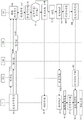
Fig. 3A schematically shows a first example of a method according to the invention for synchronizing a gateway without any synchronization means.
In the example in fig. 1, the method is applied to synchronize the femto gateway 11 so that the femto gateway 11 can become a class B gateway. In this method, femto gateway 11, which does not have any synchronization means, is assisted by another gateway (here, one of gateways 12A, 12B and 12C having synchronization means) to achieve its synchronization.
In step 32, the processing module 11 of the femto gateway 11 transmits an uplink frame including a synchronization assistance request (referred to as a synchronization assistance request frame) to the server 10 through a gateway located near the femto gateway 11. For this reason, the femto gateway 11 temporarily functions as a terminal device. The synchronization assistance request frame is transmitted in a multicast mode.
During steps 33, 34 and 35, a copy of the sync assist request frame is received by each gateway (here macro gateways 12A, 12B and 12C) that is within range of the femto gateway 11. During steps 33, 34 and 35, the content of the synchronization assistance request frame is inserted into an uplink HTTP request intended for the server 10, by each gateway that has received said frame. Each gateway that has received the synchronization assistance request frame then sends an uplink HTTP request containing the synchronization assistance request to the server 10.
The sync assistance request sent at step 32 includes a unique identifier AddID that enables the server 10 to determine which gateway has made the sync assistance request. The unique identifier AddID is similar to an address. Therefore, it is considered hereinafter that the unique identifier AddID represents an address (referred to as a synchronization address). In the example of fig. 1, the sync assistance request includes a unique identifier AddID of femto gateway 11. It is assumed that the server 10 is capable of uniquely associating a unique identifier AddID with the gateway of the LoRa network 1, wherein the unique identifier AddID is received by the synchronization assistance frame and the gateway of the LoRa network 1 inserts said unique identifier AddID into said synchronization assistance frame. In one embodiment, each gateway in the LoRa network 1 obtains a unique identifier AddID when it is installed in the LoRa network 1.
In one embodiment, the synchronization assistance request includes information representative of a sub-period PS ("ping slot") of the communication period during which the femto gateway 11 wishes another gateway to transmit a synchronization frame to. It should be noted that the sub-period PS for transmitting the synchronization frame is located at a fixed position in the communication period. Preferably, the sub-period PS for transmitting the synchronization frame is close to the beacon after the communication period including the sub-period PS. For example, the sub-period PS is the last sub-period of the communication period, and the last sub-period of the communication period is located just before transmission of a beacon immediately after the communication period including the sub-period PS. By adopting a sub-period PS, which is preferably located a little before the transmission of the beacon, the risk of clock drift of the femto gateway 11 during the communication period after the beacon is limited. The synchronization frame is described hereinafter.
In one embodiment, femto gateway 11 starts a time counter after sending the sync assist request frame. If no response to the sync assist request frame is received after a predefined period of time (time out), femto gateway 11 may decide to update its sync assist request by sending a new sync assist request frame. Further, for example, in NrSecond (N)rIs an integer greater than 0), the femto gateway 11 ends its synchronization assistance request if no response to the request is received after the synchronization assistance request update. As such, the femto gateway cannot function in class B communication codes.
During step 36, server 10 receives a plurality of uplink HTTP requests, wherein each of the plurality of uplink HTTP requests contains the same synchronization assistance request made by femto gateway 11 and relayed through macro gateways 12A, 12B, and 12C.
In step 37, the processing module 100 checks that the synchronization assistance request indeed comes from a gateway in the LoRa network 1 by using the unique identifier AddID contained in the request. Step 37 is optional because it is only implemented when there is a risk that a sync assist request frame from a gateway in the LoRa network other than the LoRa network 1 may be received by a gateway in the LoRa network 1.
In step 38, the processing module 100 checks the feasibility of the synchronization aid. To this end, the processing module 100 checks whether at least one gateway among the gateways of the LoRa network 1 relaying the synchronization assistance request can assist the femto gateway 11 in synchronization. It is in fact necessary to enable the first gateway to assist the synchronization of the second gateway, equipping the first gateway with synchronization means, for example a GPS module. It is assumed here that each gateway equipped with a synchronization means has transmitted this information to the server 10. Thus, the processing module 100 is able to determine which of the macro gateways 12A, 12B, and 12C is equipped with a synchronization device. Furthermore, the processing module 100 knows which gateways in the LoRa network 1 are within range of the femto gateway 11. This is because the gateways in range are gateways that have relayed the synchronization assistance request, i.e., macro gateways 12A, 12B, and 12C in the case of the example in fig. 1. The processing module 100 considers synchronization assistance to be possible if at least one of the gateways relaying the synchronization assistance request is equipped with a synchronization means. Otherwise, synchronization assistance is not possible.
In step 39, processing module 100 decides to accept or reject and sends a message including information indicating the decision to femto gateway 11.
When synchronization assistance is not possible, the decision made by the processing module is a rejection. In this case, the message sent to the femto gateway 11 is a reject message. The rejection message is, for example, a downlink HTTP request including information indicating the rejection. The message is sent on link 15D during step 40.
In step 41, the processing module 110 of the femto gateway 11 receives the rejection message and ends its attempt to synchronize.
When synchronization assistance is possible, the processing module 100 enables synchronization assistance. In this case, during step 42, the processing module 100 designates one of the macro gateways 12A, 12B or 12C for relaying information representing a response to the synchronization assistance request. For example, each uplink HTTP request contains information indicating the quality of reception of the synchronization assistance request frame by the gateway transmitting the uplink HTTP request. The processing module 100 specifies, for example, the gateway that receives the synchronous assistance request frame with the best quality. In the example of fig. 1, macro gateway 12A is specified by processing module 100. In one embodiment, the gateway designated to respond to the request for synchronization assistance is also the gateway that provides synchronization assistance.
In step 43, the processing module 100 transmits a downlink HTTP request including information representing a response to the synchronization assistance request to the macro gateway 12A. The information indicating the response includes the unique identifier AddID of the gateway requesting synchronization assistance (here, femto gateway 11). As described below, the information representing the response transmitted to the macro gateway 12A in the downlink HTTP request makes it possible to establish the transmission of at least one synchronization frame through the macro gateway 12A to the femto gateway 11 in the sub-period PS of at least one communication period, thereby making it possible for the femto gateway 11 to determine the beacon transmission timing synchronized with the beacon transmission timing from each class B gateway in the LoRa network 1.
In one embodiment, the information indicating the response further includes information indicating the sub-period PS that must be used for transmitting the synchronization frame if the sub-period PS is different from the sub-period proposed by the processing module 110 of the femto gateway 11 in the synchronization assistance request frame.
In one embodiment, the information representative of the response further comprises a synchronization address represented by an identifier (referred to as global identifier pingadid), wherein the synchronization address represented by the identifier is the address used as destination address in the sync assistance frame, the global identifier pingadid being able to be different from the unique identifier AddID used by the femto gateway 11 in its sync assistance request step 32. This is particularly useful, for example, if a synchronization assistance procedure has been established by the server 10 for a second femto gateway (not shown in fig. 3A) by one macro gateway located in the vicinity of the femto gateway 11. The global identifier pingadid used in the synchronization frames intended for the second femto gateway enables the femto gateway 11 to use them without having to generate a new synchronization frame specifically for the femto gateway 11 with its unique identifier AddID. In this way, multiple gateways (here femto gateway 11 and at least one other femto gateway) can synchronize themselves by means of the same gateway (here macro gateway 12A) using the same synchronization frame. Thus, the global identifier pingadid is information enabling a plurality of gateways to determine at least the next time when a beacon is transmitted through each class B gateway in the LoRa network 1 and to transmit a beacon at each determined next transmission time. In one embodiment, when the second femto gateway has received synchronization frames with a unique identifier AddID equal to the value AddID _ FT2 as destination address, it may be advisable to use these same frames to assist the synchronization of the femto gateway 11. This is done by fixing the global identifier pingadid in the response to the synchronisation assistance request of the femto gateway 11 at the value AddID _ FT2 of the unique identifier AddID of the second femto gateway. In this way, it is avoided to keep the global identifier value pingadid in addition to the unique identifier value AddID.
In step 44, a downlink HTTP request containing information indicative of a response to the synchronization assistance request is received by macro gateway 12A. The response enables the macro gateway 12A to determine in which sub-period PS of at least one communication period the macro gateway 12A has to transmit the synchronization frame, and to determine which address: a synchronization address represented by the unique identifier addrid if the global identifier pingadid is not present in the information representing the response to the sync assistance request, or a synchronization address represented by the global identifier pingadid if the global identifier pingadid is present in the information representing the response to the sync assistance request. Macro gateway 12A extracts the information and inserts the extracted information into a downlink frame for the gateway corresponding to the unique identifier AddID (i.e., femto gateway 11). The downlink frame is transmitted in a multicast mode.
In step 45, processing module 110 of femto gateway 11 receives a downlink frame including information representing a response to the synchronization assistance request frame from macro gateway 12A. Receiving the downlink frame enables femto gateway 11, through its processing module 110, to determine at least one communication period during which femto gateway 11 must receive a synchronization frame from macro gateway 12A. For example, receiving a downlink frame represents to sub-gateway 11: upon receiving NBAfter a beacon, femto gateway 11 will be receiving NBAt least one synchronization frame from the macro gateway 12A is received in a transmission period following the beacon. Then, the femto gateway 11 uses each received synchronization frame for synchronizing itself. The sub period PS indicated in the frame with the sync assistance requestEach synchronization frame is received in the sub-period PS of the corresponding communication period or in the sub-period PS of the communication period corresponding to the sub-period PS indicated in the downlink frame including the information representing the response to the synchronization assistance request. In one embodiment, the number of beacons NBIs predefined and known to each gateway in the LoRa network 1. In one embodiment, the number of beacons NBThat is, the communication period after receiving the next beacon includes one sub-period PS of the transmission synchronization frame. In one embodiment, the number of beacons NB=5。
In one embodiment, the number of beacons NBForming part of the information representing the response to the synchronization assistance request. Thus, the number of beacons NBIs received in a downlink frame that includes information indicative of a response to the synchronization assistance request.
In step 46, the processing module 110 obtains information representative of the sub-period PS used by the macro gateway 12A for transmitting the synchronization frame. This information is known to the processing module 110 because it was defined during step 32 or it was extracted from the downlink frame including information representing a response to the synchronization assistance request frame received during step 45.
In embodiments where the global identifier pingadid is included in the information representing a response to the sync assist request frame, the processing module 110 uses a sync frame, wherein the destination address of the sync frame comprises the global identifier pingadid instead of the unique identifier AddID to synchronize itself.
In step 47, the processing module 110 starts a counter and counts the number of beacons received after receiving a downlink frame including information indicating a response to the synchronization assistance request.
Simultaneously with step 47, after transmitting a downlink frame including information representative of a response to the synchronization assistance request, during step 48 the processing module 120 of the macro gateway 12A starts a counter and counts the number of beacons transmitted after transmission of said downlink frameAnd (4) counting. When the number of transmitted beacons reaches the number of beacons NBThe processing module 120 proceeds to step 49 during which it transmits a synchronization frame in the sub-period PS of the next communication period during step 49. If the processing module 120 of the macro gateway 12A has received another downlink HTTP request containing information representing a response to the synchronization assistance request before receiving the last downlink HTTP request containing information representing a response to the synchronization assistance request, the processing module 120 considers the information representing the response contained in the last downlink HTTP request if the information is different between the two downlink HTTP requests.
When the number of beacons received by femto gateway 11 reaches the number of beacons NBThen, the processing module 110 of the femto gateway 11 proceeds to step 50. Then, the femto gateway 11 waits until it receives the synchronization frame in the sub period PS of the next communication period. During step 50, the processing module 110 receives a synchronization frame. The processing module 110 then knows that the synchronization frame has been received during the sub-period PS. Through its knowledge of the LoRaWAN protocol, the processing module 110 knows the predefined difference between the next beacon sent by each class B gateway ( macro gateways 12A, 12B and 12C) in the LoRa network 1 and the sub-period PS. By receiving the time of the synchronization frame and the predefined distance, the processing module 110 determines at least the next time at which a beacon is transmitted by each class B gateway in the LoRa network 1 (here, macro gateways 12A, 12B, and 12C). Knowing the period of beacons in the LoRa network 1, the processing module 110 may then synchronize its own beacon transmissions with the beacon transmissions of the other class B gateways (here, macro gateways 12A, 12B, and 12C) in the LoRa network 1. A single reception of the synchronization frame is sufficient to synchronize the beacon transmission of the femto gateway 11 if the femto gateway comprises a reliable clock. If the femto gateway's clock is not reliable enough, the beacon transmissions must be synchronized periodically to compensate for the femto gateway's 11 clock drift.
After receiving the synchronization frame during step 50, the processing module 110 transmits a beacon at step 51 at each transmission time determined during step 50. In other words, the processing module 110 transmits at least one beacon synchronized with beacons (not shown in fig. 3A) transmitted by other class B gateways in the LoRa network 1.
In one embodiment, a plurality of synchronization frames are transmitted with a predetermined period P. Accordingly, femto gateway 11 may resynchronize each time a synchronization frame is received (repeating steps 49, 50 and 51). The period P is, for example, a default period known to each gateway in the LoRa network 1. In one embodiment, period P is defined by femto gateway 11, and information representing this period is transmitted in a sync assist request frame in the direction of server 10. The server 10 then transmits information indicating the period to a gateway in the network 1 designated to assist the femto gateway 11 in synchronizing itself. In one embodiment, the period P is defined by the server 10, wherein the server 10 transmits information representative of the period P to gateways in the network 1 designated to assist the femto gateway 11 in synchronizing itself and to the femto gateway 11.
In one embodiment, the synchronization frame contains the unique identifier AddID of the gateway for which it is intended (here femto gateway 11) if the global identifier pingadid is not present in the information representing the response to the synchronization assistance request. In an embodiment the sync frame contains the global identifier pingadid as the destination address if said global identifier pingadid is present in the information representing the response to the sync assistance request.
In one embodiment, the synchronization frame further includes information indicating the time at which the synchronization frame is transmitted by the macro gateway 12A. The time at which the synchronization frame is transmitted enables femto gateway 11 to calculate the time taken to propagate the frame between macro gateway 12A and femto gateway 11 and to take this propagation time into account during synchronization. In this way, the synchronization becomes reliable.
As is known, in a LoRa network, the sub-period of the communication period attributed to a conventional class B terminal device changes in a deterministic manner between two beacon transmissions. In one embodiment, when the sub-period PS for transmitting the synchronization frame coincides with the sub-period belonging to other communications by the gateway (here, the macro gateway 12A) to transmit the synchronization frame, the processing module 100 of the server 10 temporarily or explicitly designates another gateway in the LoRa network 1 within range of the femto gateway 11 for transmitting the synchronization frame.
In one embodiment, synchronization assistance is granted, i.e., the synchronization method described in conjunction with fig. 3A is implemented during period D. During period D, femto gateway 11 transmits a beacon and synchronizes its beacon transmission with each synchronization frame it receives. In one embodiment, during period D, macro gateway 12A periodically transmits synchronization frames at a period P. In one embodiment, period D is a default period known to each gateway in the LoRa network 1. For example, period D may be equal to 24 hours or infinity. In one embodiment, period D is fixed by server 10 and is received by processing module 110 of femto gateway 11 in response to the synchronization assistance request during step 45. To this end, server 10 may analyze the traffic due to class B terminal devices in the geographical area including femto gateway 11 and locate rich regular periods of overloading macro gateways 12A, 12B and 12C (i.e., periods of overloading of LoRa network 1). In this way, femto gateway 11 may be used to mitigate macro gateways 12A, 12B, and 12C. Period D may then be defined in terms of these rich periods. In one embodiment, at the end of period D, femto gateway 11 updates its synchronous assistance request by restarting the method described in connection with figure 3A, if necessary. In another embodiment, which is an alternative to the previous embodiment, the server 10 actively updates the synchronization assistance. In this case, the processing module 100 of the server 10 repeats the method described in connection with fig. 3A starting from step 43 and implements steps 44 to 51.
In one embodiment, processing module 100 of server 10 observes communications from terminal devices using femto gateway 11 once synchronization assistance has begun. In the event of an abnormal function of these communications, the processing module 100 of the server 10 ends the synchronization assistance without waiting for the end of the period D. The abnormal function is characterized by, for example, the number of repetitions of the frame passing through femto gateway 11, which is greater than a predetermined threshold. The processing module 100 of the server 10 notifies the femto gateway 11 of the end of the synchronization assistance by, for example, transmitting thereto a downlink HTTP request containing information indicating the end of the synchronization assistance, or by requesting another gateway in the LoRa network 1, transmitting to the femto gateway 11 a frame containing information indicating the end of the synchronization assistance.
In one embodiment, the sync assist request frame, the sync assist request response frame, and the sync frame are frames dedicated for sync assist that supplement existing frames defined in the LoRaWAN protocol.
In one embodiment, the sync assist request frame, the sync assist request response frame, and the sync frame are existing frames in the LoRaWAN protocol in which new fields are inserted for transmitting information and/or data exchanged when implementing the synchronization method described in connection with FIG. 3A.
In one embodiment, the sync assist request frame, the sync assist request response frame, and the sync frame are existing frames in the LoRaWAN protocol in which fields not used by the LoRaWAN protocol are used to transmit information and/or data exchanged during implementation of the synchronization method described in connection with fig. 3A.
In the above it is observed that during steps 40 and 41 the reject message explicitly ends the synchronization assistance procedure. In an alternative embodiment, the reject message invites femto gateway 11 to update the transmission of the synchronization assistance request frame at a later time. In this case, after receiving the rejection message, for example, a predefined waiting period, femto gateway 11 again implements step 32 by transmitting a new synchronization assistance request frame.
In one embodiment, prior to performing step 32, processing module 110 of femto gateway 11 transmits a first synchronization assistance request (referred to as a preliminary synchronization assistance request) over link 15D without going through macro gateways 12A, 12B, and 12C. This preliminary synchronization assistance request is transmitted, for example, in the form of an uplink HTTP request containing the same information as transmitted during steps 33, 34 and 35. When it receives the uplink HTTP request, the processing module 100 of the server 10 performs a preprocessing procedure, thereby enabling the server 10 to determine whether the femto gateway 11 can be enabled to transmit a synchronization assistance request frame. During this preprocessing procedure, processing module 100 analyzes the load on the LoRa network 1, for example, in the geographic area containing femto gateway 11. If the load on the LoRa network 1 is higher than a predefined load level due to class B end devices, the processing module 100 decides to enable the femto gateway 11 to implement the synchronization method described in connection with fig. 3A. To this end, processing module 100 transmits a downlink HTTP request to femto gateway 11, indicating that it is initiated to send a synchronization assistance request frame. After receiving the downlink HTTP request, the processing module 110 of the femto gateway 11 implements step 32. If the load on the LoRa network 1 is less than or equal to the predefined load level due to the class B terminal device, the processing module 100 sends a rejection message to the femto gateway 11. As described above, the rejection message may be an invitation to explicitly reject or update the synchronization assistance request on a subsequent date. The subsequent date may be predefined and known by each gateway in the LoRa network 1, defined by the femto gateway 11, or defined by the processing module 100 of the server 10 and transmitted in a reject message. In one embodiment, processing module 100 decides to consider the femto gateway 11 request when the load on the LoRa network is less than or equal to a predefined load level, rather than allowing femto gateway 11 to update the synchronization assistance request on a subsequent date. After a given period of time, if processing module 100 finds that the load on LoRa network 1 in the geographical area containing femto gateway 11 exceeds a predefined load level, it can cause femto gateway 11 to implement step 32.
In one embodiment, if period D is not infinite, femto gateway 11 transmits a preliminary synchronization assistance request to obtain an update for period D. One advantage of this embodiment is that the server 10 permits updating of period D only when the pre-processing procedure enables period D. In this way, the implementation of the synchronization assistance procedure is updated only when the load on the LoRa network 1 confirms the implementation of the synchronization assistance procedure.
Until then, the start of the synchronization assistance procedure is always under the initiative of the femto gateway 11. In one embodiment, server 10 decides to help femto gateway 11 synchronize itself without receiving a synchronization assistance request in advance, so that femto gateway 11 may function in the class B communication mode. For example, after analyzing the load on the LoRa network 1 due to the class B terminal device, the present embodiment is implemented when the server 10 finds that the LoRa network 1 is overloaded in the geographical area including the femto gateway 11. To this end, the server 10 sends, through its processing module 100, a request for implementing step 32 to the femto gateway 11. This request is transmitted, for example, in the form of a downlink HTTP request including information indicating a request to initiate a synchronization process transmitted to femto gateway 11 using link 15D. After receiving the downlink HTTP request, the processing module 110 of the femto gateway 11 implements step 32.
In one embodiment, the femto gateway 11 does not permanently have a unique identifier AddID. The unique identifier is attributed to gateway 11 by processing module 100 of server 10 during the transmission of a request to start the synchronization assistance procedure (the unique identifier AddID is then included in the downlink HTTP request containing information representative of the request to start the synchronization assistance procedure), or during the transmission of the downlink HTTP request to femto gateway 11 indicating that it is started to carry out the synchronization assistance procedure.
In one embodiment, the femto gateway 11 does not define the sub-period PS. In this case, the sync assist request frame transmitted by the sub-gateway 11 does not include this information. Then, the processing module 100 of the server 10 defines the sub-period PS. In this way, the processing module 100 transmits information representative of the sub-period PS in a downlink HTTP request comprising information representative of a response to the synchronization assistance request transmitted to the macro gateway 12A, whereas said information is intended for the femto gateway 11.
In one embodiment, the femto gateway 11 checks whether other gateways are in range for receiving the synchronization assistance request frame and for transmitting the synchronization frame thereto, before transmitting the synchronization assistance request frame during step 32. Such checking may rely on analysis of beacons received by the femto gateway 11. The receipt of a beacon indicates that at least one gateway is within range of femto gateway 11. If no gateways are in range, femto gateway 11 does not implement the method described in connection with fig. 3A.
Fig. 3B schematically shows a second example of a method for synchronizing a gateway without synchronization means according to the present invention.
The method described in connection with fig. 3B is very similar to the method described in connection with fig. 3A and may be substituted for the method described in connection with fig. 3A. Steps 32 to 43, 45 to 47, 50 and 51 remain the same. Step 44 is replaced by step 440 performed by macro gateway 12A. Step 48 performed by macro gateway 12A is replaced by step 480 performed by server 10. Step 49 performed by macro gateway 12A is replaced by step 490 performed by server 10 and step 491 performed by macro gateway 12A.
In the method described in connection with fig. 3B, the server 10 transmits a downlink HTTP request to the macro gateway 12A for each synchronization frame. Thus, the server 10 completely controls the transmission of the synchronization frame. In the present method, the macro gateway 12A is only used to relay downlink HTTP requests from the server 10 to destinations in the LoRa network 1, without intending on the content of the requests (conventional function of the gateway of the LoRa network). By default, any downlink HTTP request contains all the information required by the macro gateway 12A in order to form a frame to be sent at the moment determined by the server 10.
During step 440, a downlink HTTP request containing information representing a response to the synchronization assistance request is received by the macro gateway 12A. Macro gateway 12A extracts the information and inserts the extracted information into a downlink frame intended for the gateway corresponding to the unique identifier AddID (i.e., femto gateway 11) or into a downlink frame intended for each gateway identified by the global identifier pingadid. The downlink frame is transmitted in a multicast mode. Unlike step 44, during step 440, the macro gateway 12A does not determine in which subinterval PS of at least one communication period the macro gateway 12A has to transmit the synchronization frame, and to which destination (AddID or pingadid). In the method described in connection with fig. 3B, femto gateway 11 receives a downlink frame containing information representing a response to the synchronization assistance request during step 45 as already explained.
After transmitting the downlink HTTP request including the information indicating the response to the synchronization assistance request, the processing module 100 of the server 10 starts a counter and counts the number of beacons transmitted after transmitting the downlink HTTP request during step 480. When the number of transmitted beacons reaches the number of beacons NBAt this time, the processing module 100 proceeds to step 490, during which it transmits a downlink HTTP request containing information indicating that a synchronization frame is transmitted during the sub-period PS of the next communication period. This downlink HTTP request enables it to trigger the macro gateway 12A to send a synchronization frame in the sub period PS of the next communication period during step 491. The femto gateway 11 performs step 50 after receiving the synchronization frame. Step 490 repeats during time period D.
In the case where the sub-period PS coincides with a sub-period attributed to the macro gateway 12A for communicating a frame (referred to as a legacy frame) other than the synchronization frame (a frame including application data or control information), the server 10 may request the macro gateway 12A to cause transmission of the legacy frame. However, after receiving the synchronization request response frame, the femto gateway 11 expects to receive a synchronization frame in the sub period PS, and it uses a legacy frame as a synchronization frame for synchronizing its beacon transmission.
In the present embodiment, the server 10 precisely controls the duration of the synchronization assistance by controlling when to transmit the downlink HTTP request, thereby making it possible for the macro gateway 12A to trigger the transmission of the synchronization frame.
Claims (21)
1. Method for synchronizing gateways in a remote wireless network providing low energy consumption, said method being for said gateways to function according to a communication mode known as class B, wherein a communication period is defined by the periodic transmission of beacons by each gateway in said network supporting said communication mode, said gateways being called class B gateways, the transmission of beacons being synchronized between each class B gateway, each communication period being divided into a predefined number of subintervals, a terminal device of said network functioning according to said communication mode being able to bidirectionally communicate with a server through a class B gateway only during the subintervals allocated thereto, when said method is implemented by a first gateway, characterized in that it comprises:
transmitting, by at least one second gateway of the network, a first frame comprising a synchronization assistance request to the server;
receiving a second frame including information representing a response to the request from a gateway in the network equipped with a synchronization device, the gateway in the network equipped with a synchronization device being referred to as a designated gateway, the designated gateway being designated by the server among the at least one second gateway, the receiving the second frame causing the first gateway to determine at least one communication period during which the first gateway must receive a third frame from the designated gateway, the third frame being referred to as a synchronization frame;
obtaining information representative of the determined sub-period of each communication period used by the designated gateway to transmit synchronization frames, the sub-period having a predefined offset from a beacon located directly after the communication period;
receiving at least one synchronization frame; and
for each synchronization frame received:
determining at least one next time to transmit a beacon for each class B gateway in the network by receiving the time of the synchronization frame and the predefined offset; and
a beacon is transmitted at each determined next transmission time.
2. The method of claim 1, wherein, prior to transmitting the first frame comprising a synchronization assistance request, the first gateway checks whether at least one second gateway is within range for receiving the first frame and for transmitting a third synchronization frame to the first gateway,
if no gateway is in range, the first frame including the request for synchronization assistance is not transmitted.
3. The method of claim 1, wherein after transmitting the first frame comprising the synchronization assistance request, the first gateway updates the synchronization assistance request by transmitting a new fixed frame comprising the synchronization assistance request if a response to the first frame is not received after a predetermined time.
4. Method for synchronizing gateways in a remote wireless network providing low energy consumption, said method being for said gateways to function according to a communication mode known as class B, wherein a communication period is defined by the periodic transmission of beacons by each gateway in said network supporting said communication mode, said gateways being referred to as class B gateways, the transmission of beacons being synchronized between each class B gateway, each communication period being divided into a predefined number of subintervals, a terminal device of said network functioning according to said communication mode being able to bidirectionally communicate with a server through a class B gateway only during the subintervals allocated thereto, said method comprising, when implemented by said server:
receiving at least one request, the request comprising a synchronization assistance request made by a first gateway and relayed by at least one second gateway;
checking the feasibility of a synchronization aid, which is possible when at least one of the at least one second gateway is equipped with a synchronization means;
designating a second gateway equipped with a synchronization device for relaying information representing a response to the synchronization assistance request to a first gateway, referred to as designated gateway, when synchronization assistance is possible, said information enabling a transmission of at least one frame by said designated gateway to said first gateway in a predefined sub-period of at least one communication period, said at least one frame being referred to as synchronization frame, wherein each transmission of a synchronization frame enables said first gateway to determine at least one moment of sending a beacon synchronized with the transmission moment of the beacon of each class B gateway in the network; and
transmitting a request including the information to the specified gateway.
5. Method for synchronizing gateways in a remote wireless network providing low energy consumption, said method for enabling said gateways to function according to a communication mode known as class B, wherein a communication period is defined by the periodic transmission of beacons by each gateway in said network supporting said communication mode, said gateways being referred to as class B gateways, the transmission of beacons being synchronized between each class B gateway, each communication period being divided into a predefined number of subintervals, a terminal device of said network functioning according to said communication mode being able to bidirectionally communicate with a server through a class B gateway only during the subintervals allocated thereto, when said method is implemented by a second gateway in said network, wherein said second gateway is class B and is equipped with synchronization means, said method comprising:
receiving a request from the server, the request including information representing a response to a synchronization assistance request made by a first gateway, the synchronization assistance request having been relayed to the server by the second gateway;
transmitting a frame to the first gateway including the response to the synchronization assistance request, the response enabling the first gateway to determine in which sub-period of at least one communication period the first gateway must receive a synchronization frame; and
transmitting at least one synchronization frame to the first gateway in the sub-period, the receiving of a synchronization frame in the sub-period enabling the first gateway to determine at least one time at which to transmit a beacon in synchronization with the time at which the beacon of each class B gateway is transmitted in the network.
6. Method for synchronizing gateways implemented in a remote wireless network providing low energy consumption, for causing said gateways to function according to a communication mode known as class B, wherein a communication period is defined by the periodic transmission of beacons by each gateway in said network supporting said communication mode, said gateways being called class B gateways, the transmission of beacons being synchronized between each class B gateway, each communication period being divided into a predefined number of sub-periods, a terminal device of said network functioning according to said communication mode being able to communicate bi-directionally with a server through a class B gateway only during the sub-periods allocated thereto, said method being implemented by a system and comprising the method according to claim 1 implemented by a first gateway, the method according to claim 5 implemented by a second gateway being a class B gateway and equipped with synchronization means, and the method according to claim 4 implemented by a server The method is described.
7. The method of claim 6, wherein the frame including the synchronization assistance request includes a unique identifier that enables the server to determine which gateway has made the synchronization assistance request.
8. The method of claim 6, wherein a sub-period for transmitting a synchronization frame is determined by the first gateway, and wherein the information representative of a response to the synchronization assistance request comprises information representative of the sub-period.
9. The method of claim 6, wherein a sub-period for transmitting a synchronization frame is determined by the server, and wherein a frame comprising the synchronization assistance request comprises information representative of the sub-period.
10. The method of claim 6, wherein the method is implemented for a predefined time.
11. The method of claim 6, wherein a plurality of synchronization frames are transmitted at a predefined period.
12. The method of claim 6, wherein the server temporarily or explicitly designates another class B gateway equipped with a synchronization device in the network for transmitting at least one synchronization frame to the first gateway when a sub-period for transmitting the synchronization frame coincides with a sub-period belonging to a second gateway for other communications.
13. The method of claim 6, wherein prior to sending the frame including the synchronization assistance request, the first gateway transmits a preliminary synchronization assistance request to a server using a direct communication link with the server to trigger the server to perform a pre-processing procedure to cause the server to determine whether the first gateway can be caused to transmit the frame including the synchronization assistance request.
14. The method of claim 6, wherein prior to transmitting the frame comprising the request for synchronization assistance, the server transmits a request to the first gateway requesting the first gateway to transmit the frame comprising the request for synchronization assistance.
15. The method of claim 6, wherein the information representative of the response to the synchronization assistance request comprises: enabling a plurality of gateways including the first gateway to determine information of at least one future time instant at which a beacon is transmitted by each class B gateway in the network, and to transmit a beacon at each determined future transmission time instant.
16. The method of claim 6, wherein the network is a LoRa network.
17. Gateway type device comprising circuitry suitable for implementing the method according to claim 1.
18. Gateway type device comprising circuitry suitable for implementing the method according to claim 5.
19. Device of the server type comprising circuitry suitable for implementing the method according to claim 4.
20. Network system comprising at least one device according to claim 17, at least one device according to claim 18 and one device according to claim 19.
21. A non-transitory storage medium storing a computer program, the computer program comprising program code instructions loadable in a programmable device to cause the programmable device to carry out the method according to claim 1, or the method according to claim 4, or the method according to claim 5, or the method according to claim 6, when the computer program is executed by a processor of the device.
Applications Claiming Priority (3)
| Application Number | Priority Date | Filing Date | Title |
|---|---|---|---|
| FR1650688A FR3047384B1 (en) | 2016-01-28 | 2016-01-28 | METHOD FOR SYNCHRONIZING A GATEWAY IN A LORA NETWORK |
| FR1650688 | 2016-01-28 | ||
| PCT/EP2017/050896 WO2017129447A1 (en) | 2016-01-28 | 2017-01-17 | Synchronisation method for a node in a cellular network |
Publications (2)
| Publication Number | Publication Date |
|---|---|
| CN108605301A CN108605301A (en) | 2018-09-28 |
| CN108605301B true CN108605301B (en) | 2020-12-15 |
Family
ID=56117834
Family Applications (1)
| Application Number | Title | Priority Date | Filing Date |
|---|---|---|---|
| CN201780008553.3A Active CN108605301B (en) | 2016-01-28 | 2017-01-17 | Synchronization method for nodes in a cellular network |
Country Status (6)
| Country | Link |
|---|---|
| US (1) | US10470146B2 (en) |
| EP (1) | EP3409054B1 (en) |
| CN (1) | CN108605301B (en) |
| BR (1) | BR112018015070A2 (en) |
| FR (1) | FR3047384B1 (en) |
| WO (1) | WO2017129447A1 (en) |
Families Citing this family (26)
| Publication number | Priority date | Publication date | Assignee | Title |
|---|---|---|---|---|
| CN107682938A (en) * | 2017-03-20 | 2018-02-09 | 上海贝壳供应链管理有限公司 | A kind of communication system based on LORA from group agreement |
| WO2018183789A1 (en) * | 2017-03-31 | 2018-10-04 | Convida Wireless, Llc | Interworking lpwan end nodes in mobile operator network |
| CN109429325B (en) * | 2017-08-24 | 2021-03-26 | 阿里巴巴集团控股有限公司 | Data transmission method, device, base station and server |
| CN107548103B (en) * | 2017-09-28 | 2021-07-23 | 新华三技术有限公司 | Data forwarding method and device |
| US10455640B2 (en) * | 2017-12-30 | 2019-10-22 | Intel Corporation | IoT networking extension with bi-directional packet relay |
| TWI674779B (en) * | 2018-05-09 | 2019-10-11 | 奇邑科技股份有限公司 | Wireless communication system, communication method and a portable transceiver device |
| CN110557184B (en) * | 2018-05-31 | 2021-11-16 | 阿里巴巴集团控股有限公司 | Communication method and device based on relay equipment and communication method and device between terminal and base station |
| CN108934063B (en) * | 2018-09-29 | 2021-02-02 | 佛山市顺德区中山大学研究院 | Lora terminal energy-saving method based on binary search time slot randomization communication mechanism |
| FR3087081A1 (en) * | 2018-10-09 | 2020-04-10 | Sagemcom Energy & Telecom Sas | COMMUNICATION PROCESS |
| WO2020074407A1 (en) * | 2018-10-11 | 2020-04-16 | Signify Holding B.V. | Communicating in a wireless network |
| CN111050357B (en) * | 2018-10-14 | 2023-08-29 | 阿里巴巴集团控股有限公司 | Communication method and device for terminal and base station |
| CN109587023A (en) * | 2018-12-28 | 2019-04-05 | 万能 | A kind of LoRa ad hoc network method and system |
| CN109617744B (en) * | 2019-01-10 | 2020-04-28 | 电子科技大学 | LoRa minimum PingSlot number prediction method |
| US10904949B2 (en) * | 2019-03-21 | 2021-01-26 | Hall Labs Llc | Bridge for wireless communication |
| CN111757273B (en) * | 2019-03-29 | 2022-04-12 | 阿里巴巴集团控股有限公司 | Multicast communication method, system, multicast application server and terminal of communication network |
| FR3096201B1 (en) * | 2019-05-13 | 2021-05-07 | Sagemcom Energy & Telecom | FRAME ACKNOWLEDGMENT PROCESS |
| CN111988774B (en) * | 2019-05-24 | 2023-07-07 | 阿里巴巴集团控股有限公司 | Communication method and device of beacon frame in communication network |
| US11889591B2 (en) * | 2019-08-23 | 2024-01-30 | Parallel Wireless, Inc. | Integrated base station and security system |
| EP3840454B1 (en) * | 2019-12-17 | 2023-08-09 | Koninklijke KPN N.V. | Computer-implemented method and product for determining a gateway beacon transmission scheme in a low power wide area network |
| CN111132291B (en) * | 2020-01-03 | 2022-09-27 | 中科芯集成电路有限公司 | LPWAN synchronous awakening method based on LoRa |
| CN111465039B (en) * | 2020-04-13 | 2022-08-02 | 中科芯集成电路有限公司 | Wireless upgrading method based on Lora technology |
| CN112040463B (en) * | 2020-08-04 | 2024-01-30 | 广州旋坤信息科技有限公司 | Wireless communication network networking method and system based on LoRa equipment |
| CN112235745B (en) * | 2020-10-23 | 2023-03-31 | 北京航空航天大学云南创新研究院 | Multi-layer distributed LoRa network based on channel subscription |
| JP7034345B1 (en) * | 2021-01-07 | 2022-03-11 | 西日本電信電話株式会社 | Gateway, synchronization system, synchronization method, and synchronization program |
| CN114025437B (en) * | 2021-11-23 | 2023-05-23 | 重庆邮电大学 | LoRa intelligent safety helmet system ranging gateway scheduling method |
| CN115087144A (en) * | 2022-06-28 | 2022-09-20 | 苏州阿基米德网络科技有限公司 | Lora network communication method, Lora node and Lora gateway |
Citations (10)
| Publication number | Priority date | Publication date | Assignee | Title |
|---|---|---|---|---|
| CN101132222A (en) * | 2006-08-22 | 2008-02-27 | 上海贝尔阿尔卡特股份有限公司 | Gateway equipment, base station equipment, communication network and synchronization method |
| CN102014479A (en) * | 2009-12-31 | 2011-04-13 | 大唐移动通信设备有限公司 | HeNB (Home eNodeB) synchronization method, system and device |
| CN102056285A (en) * | 2011-01-18 | 2011-05-11 | 大唐移动通信设备有限公司 | Clock synchronization method, system and equipment |
| CN102781080A (en) * | 2012-07-05 | 2012-11-14 | 上海大学 | Power self-adaptive method of network access and operation of nodes of wireless sensor network |
| WO2012158578A1 (en) * | 2011-05-13 | 2012-11-22 | Qualcomm Incorporated | Method and apparatus for time and frequency tracking in clustered femtocell deployments |
| CN104394586A (en) * | 2014-11-28 | 2015-03-04 | 广州杰赛科技股份有限公司 | Synchronization method and system of miniature base station and clock server |
| CN104702662A (en) * | 2013-12-10 | 2015-06-10 | 生命安全销售股份公司 | Wireless fire system with idle mode and gateway redundancy |
| EP2273717A4 (en) * | 2008-04-24 | 2015-07-22 | Fujitsu Ltd | Node device and program |
| CN105282021A (en) * | 2014-07-18 | 2016-01-27 | 商升特公司 | Signal concentrator device |
| CN105307249A (en) * | 2015-11-09 | 2016-02-03 | 深圳市银河风云网络系统股份有限公司 | Wireless transmission system having low power consumption and transmission method thereof |
Family Cites Families (5)
| Publication number | Priority date | Publication date | Assignee | Title |
|---|---|---|---|---|
| US7230908B2 (en) * | 2000-07-24 | 2007-06-12 | Viasat, Inc. | Dynamic link assignment in a communication system |
| KR100824044B1 (en) * | 2004-06-21 | 2008-04-21 | 삼성전자주식회사 | Method and system for acquiring time sync between a base station in a communication system |
| US20110113146A1 (en) * | 2009-11-10 | 2011-05-12 | Li Gordon Yong | Dynamic quality of service (qos) setup over wired and wireless networks |
| US9706923B2 (en) * | 2014-02-25 | 2017-07-18 | General Electric Company | System and method for adaptive interference mitigation in wireless sensor network |
| BE1023514B1 (en) * | 2015-10-05 | 2017-04-12 | Henri Crohas | Method and device for wireless communication |
-
2016
- 2016-01-28 FR FR1650688A patent/FR3047384B1/en not_active Expired - Fee Related
-
2017
- 2017-01-17 WO PCT/EP2017/050896 patent/WO2017129447A1/en active Application Filing
- 2017-01-17 US US16/070,431 patent/US10470146B2/en active Active
- 2017-01-17 CN CN201780008553.3A patent/CN108605301B/en active Active
- 2017-01-17 BR BR112018015070-3A patent/BR112018015070A2/en unknown
- 2017-01-17 EP EP17700461.1A patent/EP3409054B1/en active Active
Patent Citations (10)
| Publication number | Priority date | Publication date | Assignee | Title |
|---|---|---|---|---|
| CN101132222A (en) * | 2006-08-22 | 2008-02-27 | 上海贝尔阿尔卡特股份有限公司 | Gateway equipment, base station equipment, communication network and synchronization method |
| EP2273717A4 (en) * | 2008-04-24 | 2015-07-22 | Fujitsu Ltd | Node device and program |
| CN102014479A (en) * | 2009-12-31 | 2011-04-13 | 大唐移动通信设备有限公司 | HeNB (Home eNodeB) synchronization method, system and device |
| CN102056285A (en) * | 2011-01-18 | 2011-05-11 | 大唐移动通信设备有限公司 | Clock synchronization method, system and equipment |
| WO2012158578A1 (en) * | 2011-05-13 | 2012-11-22 | Qualcomm Incorporated | Method and apparatus for time and frequency tracking in clustered femtocell deployments |
| CN102781080A (en) * | 2012-07-05 | 2012-11-14 | 上海大学 | Power self-adaptive method of network access and operation of nodes of wireless sensor network |
| CN104702662A (en) * | 2013-12-10 | 2015-06-10 | 生命安全销售股份公司 | Wireless fire system with idle mode and gateway redundancy |
| CN105282021A (en) * | 2014-07-18 | 2016-01-27 | 商升特公司 | Signal concentrator device |
| CN104394586A (en) * | 2014-11-28 | 2015-03-04 | 广州杰赛科技股份有限公司 | Synchronization method and system of miniature base station and clock server |
| CN105307249A (en) * | 2015-11-09 | 2016-02-03 | 深圳市银河风云网络系统股份有限公司 | Wireless transmission system having low power consumption and transmission method thereof |
Also Published As
| Publication number | Publication date |
|---|---|
| EP3409054A1 (en) | 2018-12-05 |
| FR3047384A1 (en) | 2017-08-04 |
| US20190053180A1 (en) | 2019-02-14 |
| FR3047384B1 (en) | 2018-11-23 |
| BR112018015070A2 (en) | 2018-12-11 |
| WO2017129447A1 (en) | 2017-08-03 |
| CN108605301A (en) | 2018-09-28 |
| EP3409054B1 (en) | 2020-02-26 |
| US10470146B2 (en) | 2019-11-05 |
Similar Documents
| Publication | Publication Date | Title |
|---|---|---|
| CN108605301B (en) | Synchronization method for nodes in a cellular network | |
| US11202242B2 (en) | Low power sensor node operation for wireless network | |
| RU2469475C2 (en) | Method of generating random access reply message group identifier and random access method | |
| CN105075302A (en) | Systems and methods for synchronization within a neighborhood aware network | |
| CN105144761A (en) | Systems and methods for identification in a neighborhood aware network | |
| EP3177087A1 (en) | Method and apparatus for gps enhanced neighbor aware network (nan) cluster discovery | |
| TW202025808A (en) | Inter-working between a time-sensitive network and a cellular communication network | |
| CN105122852A (en) | Systems and methods for discovering and synchronization within a neighbor aware network | |
| US10075516B2 (en) | Responding to a ranging request from a peer device in a wireless network | |
| CN110958681B (en) | Service transmission method and device | |
| WO2016037571A1 (en) | A method and apparatus for clock synchronization | |
| US20220353948A1 (en) | Method and device for sidelink communication | |
| US20210400605A1 (en) | Timing synchronization of 5g v2x sidelink transmissions | |
| JP6513222B2 (en) | Method and apparatus for transmitting device to device (D2D) synchronization signal | |
| US8139558B2 (en) | Method and system for establishing a system time within a mobile ad hoc network | |
| KR20150128493A (en) | Method and apparatus of synchronization in a device to device communication system | |
| JP6659147B2 (en) | Communication device, communication method, and program | |
| JP6724185B2 (en) | Synchronization method and device for communication between devices in a wireless communication system | |
| CN110677212A (en) | Time synchronization method, device and system and computer storage medium | |
| EP3384696B1 (en) | Communication apparatus, method of controlling the same, and program | |
| US11089592B2 (en) | Communication method executed in a long-range wireless network and affording low energy consumption and load management | |
| WO2012056633A1 (en) | Wireless communication device and wireless communication method | |
| WO2022027413A1 (en) | Method and device for managing sidelink transmission | |
| CN111988774B (en) | Communication method and device of beacon frame in communication network | |
| JP2005184522A (en) | Transmission/reception timing adjustment unit, wireless access unit and wireless network system |
Legal Events
| Date | Code | Title | Description |
|---|---|---|---|
| PB01 | Publication | ||
| PB01 | Publication | ||
| SE01 | Entry into force of request for substantive examination | ||
| SE01 | Entry into force of request for substantive examination | ||
| GR01 | Patent grant | ||
| GR01 | Patent grant |