CN108463173B - Ultrasonic imaging system probe and system and imaging method - Google Patents
Ultrasonic imaging system probe and system and imaging method Download PDFInfo
- Publication number
- CN108463173B CN108463173B CN201680078538.1A CN201680078538A CN108463173B CN 108463173 B CN108463173 B CN 108463173B CN 201680078538 A CN201680078538 A CN 201680078538A CN 108463173 B CN108463173 B CN 108463173B
- Authority
- CN
- China
- Prior art keywords
- frequency
- ultrasound
- analog
- imaging
- transducer
- Prior art date
- Legal status (The legal status is an assumption and is not a legal conclusion. Google has not performed a legal analysis and makes no representation as to the accuracy of the status listed.)
- Active
Links
Images


Classifications
-
- A—HUMAN NECESSITIES
- A61—MEDICAL OR VETERINARY SCIENCE; HYGIENE
- A61B—DIAGNOSIS; SURGERY; IDENTIFICATION
- A61B8/00—Diagnosis using ultrasonic, sonic or infrasonic waves
- A61B8/08—Detecting organic movements or changes, e.g. tumours, cysts, swellings
-
- A—HUMAN NECESSITIES
- A61—MEDICAL OR VETERINARY SCIENCE; HYGIENE
- A61B—DIAGNOSIS; SURGERY; IDENTIFICATION
- A61B8/00—Diagnosis using ultrasonic, sonic or infrasonic waves
- A61B8/42—Details of probe positioning or probe attachment to the patient
-
- G—PHYSICS
- G01—MEASURING; TESTING
- G01S—RADIO DIRECTION-FINDING; RADIO NAVIGATION; DETERMINING DISTANCE OR VELOCITY BY USE OF RADIO WAVES; LOCATING OR PRESENCE-DETECTING BY USE OF THE REFLECTION OR RERADIATION OF RADIO WAVES; ANALOGOUS ARRANGEMENTS USING OTHER WAVES
- G01S7/00—Details of systems according to groups G01S13/00, G01S15/00, G01S17/00
- G01S7/52—Details of systems according to groups G01S13/00, G01S15/00, G01S17/00 of systems according to group G01S15/00
- G01S7/52017—Details of systems according to groups G01S13/00, G01S15/00, G01S17/00 of systems according to group G01S15/00 particularly adapted to short-range imaging
- G01S7/52046—Techniques for image enhancement involving transmitter or receiver
-
- A—HUMAN NECESSITIES
- A61—MEDICAL OR VETERINARY SCIENCE; HYGIENE
- A61B—DIAGNOSIS; SURGERY; IDENTIFICATION
- A61B8/00—Diagnosis using ultrasonic, sonic or infrasonic waves
- A61B8/06—Measuring blood flow
- A61B8/065—Measuring blood flow to determine blood output from the heart
-
- A—HUMAN NECESSITIES
- A61—MEDICAL OR VETERINARY SCIENCE; HYGIENE
- A61B—DIAGNOSIS; SURGERY; IDENTIFICATION
- A61B8/00—Diagnosis using ultrasonic, sonic or infrasonic waves
- A61B8/48—Diagnostic techniques
- A61B8/488—Diagnostic techniques involving Doppler signals
-
- A—HUMAN NECESSITIES
- A61—MEDICAL OR VETERINARY SCIENCE; HYGIENE
- A61B—DIAGNOSIS; SURGERY; IDENTIFICATION
- A61B8/00—Diagnosis using ultrasonic, sonic or infrasonic waves
- A61B8/52—Devices using data or image processing specially adapted for diagnosis using ultrasonic, sonic or infrasonic waves
- A61B8/5207—Devices using data or image processing specially adapted for diagnosis using ultrasonic, sonic or infrasonic waves involving processing of raw data to produce diagnostic data, e.g. for generating an image
-
- G—PHYSICS
- G01—MEASURING; TESTING
- G01S—RADIO DIRECTION-FINDING; RADIO NAVIGATION; DETERMINING DISTANCE OR VELOCITY BY USE OF RADIO WAVES; LOCATING OR PRESENCE-DETECTING BY USE OF THE REFLECTION OR RERADIATION OF RADIO WAVES; ANALOGOUS ARRANGEMENTS USING OTHER WAVES
- G01S15/00—Systems using the reflection or reradiation of acoustic waves, e.g. sonar systems
- G01S15/88—Sonar systems specially adapted for specific applications
- G01S15/89—Sonar systems specially adapted for specific applications for mapping or imaging
- G01S15/8906—Short-range imaging systems; Acoustic microscope systems using pulse-echo techniques
- G01S15/8909—Short-range imaging systems; Acoustic microscope systems using pulse-echo techniques using a static transducer configuration
- G01S15/8915—Short-range imaging systems; Acoustic microscope systems using pulse-echo techniques using a static transducer configuration using a transducer array
- G01S15/8925—Short-range imaging systems; Acoustic microscope systems using pulse-echo techniques using a static transducer configuration using a transducer array the array being a two-dimensional transducer configuration, i.e. matrix or orthogonal linear arrays
-
- G—PHYSICS
- G01—MEASURING; TESTING
- G01S—RADIO DIRECTION-FINDING; RADIO NAVIGATION; DETERMINING DISTANCE OR VELOCITY BY USE OF RADIO WAVES; LOCATING OR PRESENCE-DETECTING BY USE OF THE REFLECTION OR RERADIATION OF RADIO WAVES; ANALOGOUS ARRANGEMENTS USING OTHER WAVES
- G01S7/00—Details of systems according to groups G01S13/00, G01S15/00, G01S17/00
- G01S7/52—Details of systems according to groups G01S13/00, G01S15/00, G01S17/00 of systems according to group G01S15/00
- G01S7/52017—Details of systems according to groups G01S13/00, G01S15/00, G01S17/00 of systems according to group G01S15/00 particularly adapted to short-range imaging
- G01S7/52023—Details of receivers
- G01S7/52025—Details of receivers for pulse systems
-
- G—PHYSICS
- G01—MEASURING; TESTING
- G01S—RADIO DIRECTION-FINDING; RADIO NAVIGATION; DETERMINING DISTANCE OR VELOCITY BY USE OF RADIO WAVES; LOCATING OR PRESENCE-DETECTING BY USE OF THE REFLECTION OR RERADIATION OF RADIO WAVES; ANALOGOUS ARRANGEMENTS USING OTHER WAVES
- G01S7/00—Details of systems according to groups G01S13/00, G01S15/00, G01S17/00
- G01S7/52—Details of systems according to groups G01S13/00, G01S15/00, G01S17/00 of systems according to group G01S15/00
- G01S7/52017—Details of systems according to groups G01S13/00, G01S15/00, G01S17/00 of systems according to group G01S15/00 particularly adapted to short-range imaging
- G01S7/52023—Details of receivers
- G01S7/52036—Details of receivers using analysis of echo signal for target characterisation
- G01S7/52038—Details of receivers using analysis of echo signal for target characterisation involving non-linear properties of the propagation medium or of the reflective target
-
- G—PHYSICS
- G01—MEASURING; TESTING
- G01S—RADIO DIRECTION-FINDING; RADIO NAVIGATION; DETERMINING DISTANCE OR VELOCITY BY USE OF RADIO WAVES; LOCATING OR PRESENCE-DETECTING BY USE OF THE REFLECTION OR RERADIATION OF RADIO WAVES; ANALOGOUS ARRANGEMENTS USING OTHER WAVES
- G01S7/00—Details of systems according to groups G01S13/00, G01S15/00, G01S17/00
- G01S7/52—Details of systems according to groups G01S13/00, G01S15/00, G01S17/00 of systems according to group G01S15/00
- G01S7/52017—Details of systems according to groups G01S13/00, G01S15/00, G01S17/00 of systems according to group G01S15/00 particularly adapted to short-range imaging
- G01S7/52077—Details of systems according to groups G01S13/00, G01S15/00, G01S17/00 of systems according to group G01S15/00 particularly adapted to short-range imaging with means for elimination of unwanted signals, e.g. noise or interference
-
- G—PHYSICS
- G01—MEASURING; TESTING
- G01S—RADIO DIRECTION-FINDING; RADIO NAVIGATION; DETERMINING DISTANCE OR VELOCITY BY USE OF RADIO WAVES; LOCATING OR PRESENCE-DETECTING BY USE OF THE REFLECTION OR RERADIATION OF RADIO WAVES; ANALOGOUS ARRANGEMENTS USING OTHER WAVES
- G01S7/00—Details of systems according to groups G01S13/00, G01S15/00, G01S17/00
- G01S7/52—Details of systems according to groups G01S13/00, G01S15/00, G01S17/00 of systems according to group G01S15/00
- G01S7/52017—Details of systems according to groups G01S13/00, G01S15/00, G01S17/00 of systems according to group G01S15/00 particularly adapted to short-range imaging
- G01S7/52079—Constructional features
- G01S7/5208—Constructional features with integration of processing functions inside probe or scanhead
-
- G—PHYSICS
- G01—MEASURING; TESTING
- G01S—RADIO DIRECTION-FINDING; RADIO NAVIGATION; DETERMINING DISTANCE OR VELOCITY BY USE OF RADIO WAVES; LOCATING OR PRESENCE-DETECTING BY USE OF THE REFLECTION OR RERADIATION OF RADIO WAVES; ANALOGOUS ARRANGEMENTS USING OTHER WAVES
- G01S7/00—Details of systems according to groups G01S13/00, G01S15/00, G01S17/00
- G01S7/52—Details of systems according to groups G01S13/00, G01S15/00, G01S17/00 of systems according to group G01S15/00
- G01S7/52017—Details of systems according to groups G01S13/00, G01S15/00, G01S17/00 of systems according to group G01S15/00 particularly adapted to short-range imaging
- G01S7/52085—Details related to the ultrasound signal acquisition, e.g. scan sequences
- G01S7/5209—Details related to the ultrasound signal acquisition, e.g. scan sequences using multibeam transmission
- G01S7/52092—Details related to the ultrasound signal acquisition, e.g. scan sequences using multibeam transmission using frequency diversity
-
- A—HUMAN NECESSITIES
- A61—MEDICAL OR VETERINARY SCIENCE; HYGIENE
- A61B—DIAGNOSIS; SURGERY; IDENTIFICATION
- A61B8/00—Diagnosis using ultrasonic, sonic or infrasonic waves
- A61B8/48—Diagnostic techniques
-
- G—PHYSICS
- G01—MEASURING; TESTING
- G01S—RADIO DIRECTION-FINDING; RADIO NAVIGATION; DETERMINING DISTANCE OR VELOCITY BY USE OF RADIO WAVES; LOCATING OR PRESENCE-DETECTING BY USE OF THE REFLECTION OR RERADIATION OF RADIO WAVES; ANALOGOUS ARRANGEMENTS USING OTHER WAVES
- G01S15/00—Systems using the reflection or reradiation of acoustic waves, e.g. sonar systems
- G01S15/88—Sonar systems specially adapted for specific applications
- G01S15/89—Sonar systems specially adapted for specific applications for mapping or imaging
- G01S15/8906—Short-range imaging systems; Acoustic microscope systems using pulse-echo techniques
- G01S15/8993—Three dimensional imaging systems
-
- H—ELECTRICITY
- H03—ELECTRONIC CIRCUITRY
- H03M—CODING; DECODING; CODE CONVERSION IN GENERAL
- H03M3/00—Conversion of analogue values to or from differential modulation
- H03M3/30—Delta-sigma modulation
- H03M3/458—Analogue/digital converters using delta-sigma modulation as an intermediate step
Landscapes
- Engineering & Computer Science (AREA)
- Physics & Mathematics (AREA)
- Health & Medical Sciences (AREA)
- Life Sciences & Earth Sciences (AREA)
- Radar, Positioning & Navigation (AREA)
- Remote Sensing (AREA)
- Computer Networks & Wireless Communication (AREA)
- General Physics & Mathematics (AREA)
- Surgery (AREA)
- Molecular Biology (AREA)
- Biophysics (AREA)
- Nuclear Medicine, Radiotherapy & Molecular Imaging (AREA)
- Pathology (AREA)
- Radiology & Medical Imaging (AREA)
- Biomedical Technology (AREA)
- Heart & Thoracic Surgery (AREA)
- Medical Informatics (AREA)
- Veterinary Medicine (AREA)
- Public Health (AREA)
- Animal Behavior & Ethology (AREA)
- General Health & Medical Sciences (AREA)
- Acoustics & Sound (AREA)
- Computer Vision & Pattern Recognition (AREA)
- Nonlinear Science (AREA)
- Cardiology (AREA)
- Hematology (AREA)
- Ultra Sonic Daignosis Equipment (AREA)
Abstract
An ultrasound imaging system probe includes an imaging transducer head and receive circuitry for processing received reflected ultrasound signals. The receiving circuit comprises an analog-to-digital sigma delta converter comprising a closed loop comprising a tunable bandpass filter. This enables the analog-to-digital converter to process only the desired frequency band. In this way, the ADC conversion bandwidth and ENOB are programmable, giving a more efficient probe design, and also enabling early analog-to-digital conversion in the signal processing chain.
Description
Technical Field
The invention relates to an ultrasonic imaging system probe and the whole system, and an imaging method. It particularly relates to analog-to-digital converter circuits used in such imaging applications.
Background
Harmonic ultrasound imaging is one particular type of ultrasound imaging technology that is gaining increased interest. Which utilizes the nonlinear propagation of ultrasound through body tissue. The high voltage part of the wave travels faster than the low voltage part, resulting in distortion of the shape of the wave. This change in waveform results in the generation of harmonics (fundamental frequencies or multiples of the transmit frequency) from the tissue. For example, it is known to produce images using the second harmonic because the subsequent harmonics have reduced amplitudes and are therefore insufficient to generate a suitable image.
Harmonics generated within the tissue increase with depth to a point of maximum intensity and then decrease with additional depth due to attenuation. Thus, maximum intensity is achieved at an optimal depth below the surface.
Harmonic imaging is based on the emission of relatively low frequency ultrasound waves that achieve high penetration; and reception of one or more of the harmonics of the transmitted signal that occur in the reflections due to different scatterers. In this way, a higher penetration depth can be combined with a higher specific resolution achievable for higher frequencies.
Harmonic imaging has very wide and increasing applications. It is used in classical ultrasound imaging to obtain better specific resolution with low frequency (e.g., 2.5 to 6MHz) ultrasound. When higher frequencies are used, it becomes an even more interesting imaging method, as existing methods become proportionally more complex and expensive. In particular, the low penetration depth of high frequency ultrasound requires imaging techniques that can circumvent this problem.
In addition to classical imaging applications, harmonic imaging can play an important role in applications like tissue characterization, where it can enable accurate differentiation between different tissues by providing accurate amplitude measurements at a particular frequency or combination of frequencies. Fine amplitude and frequency resolution can provide information about tissue, boundaries, and anomalies.
A problem with ultrasound imaging systems is the noisy signal of the received information. This is improved by providing the analog-to-digital conversion earlier (for digital signals, connectivity and signal processing are more robust to noise and interference), but this results in higher power consumption of the receiver circuit.
The article "A1.8V CMOS four-order Gm-C baseband sigma-delta modulated to front-end ultrasonic receivers" (in Analog Integrated Circuits and Signal Processing, volume 48, No. 2, 2006, 5, 9, 121-.
Disclosure of Invention
The invention is defined by the claims.
According to an example of an aspect of the present invention, there is provided an ultrasound imaging system probe comprising:
an imaging transducer head arranged to emit an ultrasound signal at an emission ultrasound frequency; and
a receiving circuit for processing the received reflected ultrasonic signal,
wherein the receive circuit comprises an analog-to-digital sigma delta converter comprising a closed loop including a tunable bandpass filter having a tunable center frequency and bandwidth, and
wherein a center of a pass band of the tunable bandpass filter is tunable between a first frequency and a second frequency, the first frequency corresponding to a transmit ultrasonic frequency, and the second frequency corresponding to a desired harmonic of the transmit ultrasonic frequency.
The present invention thus utilizes a bandpass sigma delta ADC. There may be one or more analog-to-digital sigma delta converters. These are devices from emerging technologies driven primarily by applications like software defined radio, where this type of converter can provide the required flexibility and programmability of the architecture. A programmable center frequency is provided and the pass band is selected by the ultrasound acquisition electronics. Furthermore, the pass band and center frequency can be accurately tuned, for example, between the transmitted signal frequencies or desired harmonics of the transmitted signal, so that the ADC can be effectively positioned to process only the desired frequency band. This can be done by introducing a band-pass tuning circuit using the known transmit frequency or its harmonics as a reference. Based on the programmable band pass filter contained in the ADC closed (feedback) loop, the probe can have very high frequency selectivity and very high amplitude resolution. The analog-to-digital converter may also have programmable clock frequency and DAC scalability.
The band pass conversion aims at optimizing energy utilization by converting only the desired frequency band.
The center of the passband of the tunable bandpass filter may thus correspond to the emitted ultrasound frequency or a desired harmonic of the emitted ultrasound frequency. The band-pass conversion affects the achievable signal-to-noise ratio, since noise outside the frequency band no longer affects operation. This enables the system to scale the band at higher resolution without linking the noise performance of the building blocks for the ADC.
The transducer head may comprise an array of transducer elements and wherein the signal processing circuitry comprises an analog-to-digital sigma delta converter for each transducer element or for groups of transducer elements of the transducer head. In this way, there is digitization at the level of the individual transducer elements.
The receiving circuit may then comprise an amplifier between each transducer element and the respective analog-to-digital sigma delta converter.
The band pass filter may be tunable between a low resolution high bandwidth mode and a high resolution low bandwidth mode. These two modes then correspond to different imaging modes for the ultrasound imaging system in which the probe is used.
The band pass filter may also be tunable to medium-resolution medium-bandwidth modes. There are then at least three different imaging modes.
The present invention also provides an ultrasound system comprising:
an ultrasound imaging system as defined above;
a controller for controlling the probe;
a beam former; and
a signal processing circuit for processing signals from the receive circuit to generate an ultrasound image.
The ultrasound system may process received reflected ultrasound signals that are harmonics of the transmitted ultrasound signals.
The controller may be adapted to control the tunable bandpass filter in synchronization with switching between different receive modes of operation of the ultrasound system. These receive modes of operation may define different resolution and bandwidth choices. The tuning of the band pass filter is thus dependent on the transmit frequency used and the receive mode used.
An example according to another aspect of the present invention provides an ultrasound imaging method including:
providing ultrasound into a volume to be imaged using an imaging transducer head; and is
Processing the received reflected ultrasonic signal by tuning a band-pass filter within a closed loop of an analog-to-digital sigma-delta converter, the band-pass filter having a tunable center frequency and bandwidth,
wherein the method comprises centering a pass band of the tunable bandpass filter to the transmit ultrasonic frequency or a desired harmonic of the transmit ultrasonic frequency.
In addition, the passband may be set to another center frequency or bandwidth. This may be required when the used transmit beamforming or signal type (e.g. buzzing) results in the occurrence of signal components in different frequency bands.
The transducer head may comprise an array of transducer elements, and wherein the method comprises performing analogue to digital conversion for each transducer element of the transducer head individually.
Drawings
Examples of the invention will now be described in detail with reference to the accompanying drawings, in which:
FIG. 1 illustrates a known ultrasound imaging system that may be modified to use the ultrasound probe design of the present invention;
FIG. 2 illustrates a first known method of analog-to-digital conversion of a probe signal in more detail;
FIG. 3 shows a second example of a known method of analog-to-digital conversion of a probe signal in more detail;
FIG. 4 shows a third example of a method of analog-to-digital conversion of a probe signal in more detail;
figure 5 shows how different ultrasound probe technologies and in particular pressure-to-electrical conversion transducers have different frequency characteristics;
FIG. 6 illustrates how different modes of operation may be used;
fig. 7 shows a known sigma delta analog to digital converter;
FIG. 8 shows a frequency characteristic of an output signal of the converter of FIG. 7;
fig. 9 shows a tunable sigma delta analog to digital converter for use in an ultrasound probe of the invention;
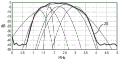
fig. 10 shows the frequency characteristics of the converter of fig. 9 in three different operating modes;
fig. 11 shows a control circuit for controlling the tuning of the tunable sigma delta analog to digital converter of fig. 9;
fig. 12 shows the tunable sigma delta analog to digital converter of fig. 9 with a first example of a tunable bandpass filter; and is
Fig. 13 shows the tunable sigma delta analog to digital converter of fig. 9 with a second example of a tunable bandpass filter.
Detailed Description
An ultrasound imaging system probe is provided that includes an imaging transducer head and a receive circuit for processing received reflected ultrasound signals. The receiving circuit comprises an analog-to-digital sigma delta converter comprising a closed loop comprising a tunable bandpass filter. This enables the analog-to-digital converter to process only the desired frequency band. In this way, the ADC conversion bandwidth and effective number of bits (ENOB) are programmable, giving a more efficient probe design, and also enabling early analog-to-digital conversion in the signal processing chain.
Referring to fig. 1, the overall operation of the ultrasonic diagnostic imaging system will first be described.
Note that the following describes the receive function of the system in particular, as the invention relates to analog to digital conversion in the receive channel.
The system includes an ultrasound probe 10, the ultrasound probe 10 having a CMUT transducer array 10' for transmitting ultrasound waves and receiving echo information. The transducer array 10' may alternatively include piezoelectric transducer elements formed of a material such as PZT or PVDF. The transducer array 10' is a one or two dimensional array of transducer elements that can be scanned in a 2D plane or scanned in three dimensions for 3D imaging.
The transducer array 10' is coupled to an (optional) microbeamformer 12 in the probe which controls the reception of signals by the CMUT array cells or piezoelectric elements. The microbeamformer is capable of at least partially beamforming signals received by groups or "tiles" of transducer elements as described in U.S. patents 5997479(Savord et al), 6013032(Savord) and 6623432(Powers et al).
The microbeamformer 12 is coupled by a probe cable to a transmit/receive (T/R) switch 16 which switches between transmit and receive and shields the main beamformer 20 from high energy transmit signals when the microbeamformer is not in use and the transducer array is operated directly by the main system beamformer. The transmission of ultrasound beams from the transducer array 10 is directed through a transducer controller 18 which is coupled through a T/R switch 16 to the microbeamformer and to a main transmit beamformer (not shown) which receives input from the operation of a user interface or control panel 38.
One of the functions controlled by the transducer controller 18 is beam steering and direction of focusing. The beams may be steered forward (orthogonal to) from the transducer array or at different angles for a wider field of view. The transducer controller 18 may be coupled to control a DC bias control 45 for the CMUT array. The DC bias control 45 sets the DC bias voltage(s) applied to the CMUT cell.
In the receive channels, partial beamformed signals are generated by the microbeamformer 12 and coupled to the main receive beamformer 20, where the partial beamformed signals from the individual patches of transducer elements are combined into a fully beamformed signal. For example, the main beamformer 20 may have 128 channels, each of which receives partially beamformed signals from a patch of tens or hundreds of CMUT transducer cells or piezoelectric elements. In this way, signals received by the thousands of transducer elements of the transducer array may effectively contribute to a single beamformed signal.
The beamformed receive signals are coupled to a signal processor 22. The signal processor 22 may process the received echo signals in various ways, such as bandpass filtering, decimation, I and Q component separation, and harmonic signal separation, which act to separate linear and nonlinear signals, thereby enabling identification of nonlinear (higher harmonics of the fundamental frequency) echo signals returned from tissue and microbubbles. The signal processor may also perform additional signal enhancement such as speckle suppression, signal compounding, and noise cancellation. The band pass filter in the signal processor may be a tracking filter whose pass band slides from a higher frequency band to a lower frequency band when echo signals are received from increasing depths, thereby rejecting noise at higher frequencies from greater depths, where these frequencies lack anatomical information.
The beamformers for transmission and for reception are implemented in different hardware and may have different functions. Of course, the receiver beamformer is designed taking into account the characteristics of the transmit beamformer. In fig. 1, only the receiver beamformers 12, 20 are shown, as the present invention relates to the receive signal processing channels. In a complete system there will also be a transmit chain with a transmit microbeamformer and a main transmit beamformer.
The function of the microbeamformer 12 is to provide an initial combination of signals in order to reduce the number of analog cables. This is typically performed in a simulated domain.
The final beamforming is done in the main beamformer 20 and usually after digitization.
The transmit and receive channels use the same transducer array 10' with fixed frequency bands. However, the bandwidth occupied by the transmit pulses may vary depending on the transmit beamforming already used. The receive channel may capture the full transducer bandwidth (which is a classical approach) or, by using band-pass processing, it may extract only the bandwidth containing useful information (e.g., harmonics of the dominant harmonics).
The processed signals are coupled to a B-mode (i.e., brightness mode, or 2D imaging mode) processor 26 and a doppler processor 28. The B-mode processor 26 uses the detection of the amplitude of the received ultrasound signals for imaging structures in the body, such as tissues of organs and blood vessels in the body. B-mode images of structures of the body may be formed in harmonic image modes or fundamental image modes or a combination of both, as described in us patent 6283919(Round et al) and us patent 6458083(Jago et al). A doppler processor 28 processes temporally different signals from tissue movement and blood flow in order to detect motion of a substance, such as the flow of blood cells in an image field. The doppler processor 28 typically includes a wall filter having parameters that can be set to pass and/or reject echoes returned from selected types of materials in the body.
For example, a wall filter may be set to have a passband characteristic that passes relatively low amplitude signals from higher velocity materials while rejecting relatively strong signals from lower or zero velocity materials. This passband characteristic will pass signals from flowing blood while rejecting signals from nearby stationary or slowly moving objects, such as the walls of the heart. The inversion feature will pass signals from moving tissue of the heart while rejecting blood flow signals, which is known as tissue doppler imaging, which detects and depicts the motion of tissue. The doppler processor receives and processes time-discrete echo signals from different points in the image field, and the sequence of echoes from a particular point is called an ensemble (ensemble). An ensemble of echoes received in rapid succession over a relatively short interval may be used to estimate the doppler shift of flowing blood, where the doppler frequency to velocity correspondence is indicative of blood flow velocity. An ensemble of echoes received over a longer period of time is used to estimate the velocity of slower flowing blood or slowly moving tissue.
The structural and motion signals produced by the B mode and doppler processors are coupled to the scan converter 32 and the multiplanar reformatter 44. The scan converter 32 arranges the echo signals in a spatial relationship according to which they are received in the desired image format. For example, the scan converter may arrange the echo signals into a two-dimensional (2D) sector format or a pyramidal three-dimensional (3D) image. The scan converter may overlay the B-mode structure image with its doppler estimated velocity using colors having corresponding motion at points in the image field to produce a color doppler image depicting motion of tissue and blood flow in the image field. The multiplanar reformatter converts echoes received from points in a common plane in a volumetric region of the body into an ultrasound image of that plane, as described in U.S. patent 6443896 (Detmer). The volume renderer 42 converts the echo signals of the 3D data set into a projected 3D image as seen from a given reference point, as described in us patent 6530885(Entrekin et al).
The 2D or 3D image is coupled from the scan converter 32, the multi-plane reformatter 44 and the volume renderer 42 to the image processor 30 for further enhancement, buffering and temporary storage for display on the image display 40. In addition to being used for imaging, the blood flow values produced by the doppler processor 28 and the tissue structure information produced by the B-mode processor 26 are coupled to a quantification processor 34. The quantification processor produces measures of different flow conditions (such as the volume rate of blood flow) as well as structural measurements (such as the size of the organ and the gestational age). The quantification processor may receive input from the user control panel 38, such as points in the anatomy of the image in which measurements are to be taken. The output data from the quantization processor is coupled to a graphics processor 36 for rendering the measurement graphics and values with an image on a display 40 and for audio output from the display device 40. The graphics processor 36 may also generate a graphic overlay for display with the ultrasound images. These graphic overlays may contain standard identifying information such as patient name, date and time of the image, imaging parameters, and the like. For these purposes, the graphics processor receives input from the user interface 38, such as a patient name. The user interface is also coupled to the transmit controller 18 to control the generation of ultrasound signals from the transducer array 10' and, thus, the images produced by the transducer array and ultrasound system. The transmit control function of the controller 18 is only one of the functions performed. The controller 18 also takes into account the mode of operation (given by the user) and the corresponding required transmitter configuration and bandpass configuration in the receiver analog-to-digital converter. The controller 18 may be a state machine having a fixed state.
The user interface is further coupled to a multiplanar reformatter 44 for selecting and controlling planes of a plurality of multiplanar reformatted (MPR) images, which may be used to perform quantitative measurements in the image field of the MPR images.
The present invention relates to signal processing of received reflected signals, and in particular it relates to analog to digital conversion. Early analog-to-digital bandpass conversion in the signal processing path enables a more efficient probe design.
Fig. 1 shows the microbeamformer 12 and the beamformer 20 prior to the signal processing path, and thus it operates in the analog domain.
There are known methods of performing signal processing in different ways, and in particular the analogue to digital conversion may be done before any beamforming is carried out. There are two different ultrasound imaging systems with earlier digitization, as depicted in fig. 2 and 3.
Fig. 2 shows the signal processing after beamforming of the received signal as a single block 50. However, this represents a combination of the various elements shown in FIG. 1 within the corresponding region 50.
In fig. 2, the received signal is processed using an analog front end 52, the analog front end 52 including a Low Noise Amplifier (LNA)54, a programmable Time Gain Compensation (TGC) amplifier 56, and an anti-aliasing filter (AAF)58, followed by an analog-to-digital converter 60. A transmit receive (T/R) switch 16 is shown which includes analog multiplexing such that the analog multiplexer selects a reduced number of groups of transducer elements to be connected to the beamformer. The selected group of elements is then updated electronically for each acoustic line. The method is used, for example, in 2D ultrasound. Which digitizes the signal before performing digital beamforming in the beamformer 20. The analog-to-digital conversion itself is not performed in the probe. Instead, long and expensive cables are used to connect the signals to the back end. Element 54 is in the probe and there is a long cable between element 54 and element 56.
In fig. 3, which shows an architecture that is typically used for 3D imaging, there is analog microbeamforming of individual pixels of a group, followed by digital beamforming for the group. As shown, the transducer elements of the transducer array 10' are divided into sub-arrays 10a.. 10 n. Within each sub-array, each transducer has a Low Noise Amplifier (LNA)54, and a programmable Time Gain Compensation (TGC) amplifier 56, followed by the microbeamformer 12 operating in the analog domain. There is then summation of the signals for the sub-arrays, followed by analog-to-digital conversion using the analog-to-digital converter 60, followed by beam beamforming using the beam forming unit 20.
The ultrasound system also distinguishes where the different functional blocks are located. In fig. 2, for example, only part of the analog front end 52 is typically implemented in an ultrasound probe. In contrast, amplification, filtering, beamforming, and control are implemented in a backend system located in the scanner.
In addition, each system has multiple channels, each with a transmitter and a switch (including a diode bridge) that allows the passage of high voltage transmit pulses to the transducer elements, but prevents these pulses from reaching sensitive receivers. The echo returns to each receiver, which includes a series of amplifiers, including one with a variable gain for the TGC under user control. The output of each channel is passed to a receive beamformer 20.
Pulse echo signals from the body are received by the array elements and passed through individual user adjustable TGC amplifiers to compensate for attenuation of the echo by body attenuation and refraction over distance. These signals are then passed to the receive beamformer 20.
Figure 4 shows in schematic form a digitised highly parallel front end. Each transducer element is coupled to an associated amplifier 20 incorporating a Time Gain Compensation (TGC) function. The method provides early digitization of the received signal. The analog to digital conversion may then be implemented in the probe such that the connection cable follows the conversion to the digital domain.
The output from amplifier 20 is digitized in analog-to-digital converter 60 before buffering in first-in-first-out (FIFO) register 62, register 62 implementing a variable delay before summing in adder 64.
There are many benefits of using early digitization for many types of transducer configurations, including transducers used for 3D imaging.
Early digitization, however, specifically placed demands on the size and power consumption of the front-end electronics and ADC functionality. The requirements of the ADC function in terms of resolution (such as the number of significant bits ENOB and the conversion bandwidth BW) may vary significantly from one mode of operation to another. ENOB and BW are the two most important parameters determined by the requirements of the particular application (imaging mode or key feature extraction from imaging). These parameters also determine the detailed specifications of the individual building blocks to be added throughout the imaging system.
In ultrasound imaging systems, the available signal frequency band is determined by the frequency response of the ultrasound transducer. As illustrated in fig. 5, different transducers operate in different frequency ranges (the acoustic performance of which varies with the transmit frequency). Figure 5 shows signals versus frequency for PZT, CMUT and crystal (XTAL) transducers.
Lower frequencies enable more penetration and higher frequencies enable improved tissue filling, finer detail and third harmonic imaging. Higher order harmonic imaging can be achieved by using a broadband transducer or by using a narrowband transducer at the harmonic imaging frequency.
The CMUT transducer has the widest frequency band of operation. At the same time, the full frequency bandwidth is never used all the time. In practice, most imaging modes use only part of the total frequency band, as shown in fig. 6.
Figure 6 shows different frequency responses of CMUT transducers for different imaging modes. The black plot 20 shows the spectral live doppler measurement mode. More details about the CMUT transducer frequency response for different imaging modes can be found in WO 2015/028945 A3.
Attenuation of the ultrasonic waves in the medium is a substantial factor affecting the configuration of the front-end electronics. The ultrasound is attenuated on a logarithmic scale rather than a linear scale.
The invention is based on the following recognition: an adjustable bandpass signal processing method may be used to adjust the bandwidth and resolution of each measurement according to the requirements of each imaging mode.
The conventional ADC is low-pass, meaning that it can be switched to be positioned at DC and frequency FNWherein F isNIs the nyquist frequency of the system.
Fig. 7 shows the structure of a sigma delta ADC suitable for ultrasound image processing.
The mode input i (t) is low pass filtered in filter 70 before being clocked by the 1-bit analog-to-digital converter 72 to generate a digital output o [ Ts ]. The feedback path includes a 1-bit digital-to-analog converter 74 and the analog feedback signal fb (t) is combined with the input to derive the difference signal d (t) which is supplied to the low pass filter 70.
Note that multi-bit ADCs and DACs may instead be used in the feedback loop.
Fig. 8 shows a desired signal band 80, nyquist frequency 82 and oversampling frequency band 84.
In its classical low-pass operation, the converter converts a considerable signal bandwidth, which may exceed the bandwidth of the desired input signal several times. Furthermore, the accuracy that can be achieved depends strongly on how large the conversion bandwidth is. Clearly, in the case when the desired signal is in a narrow band at high frequencies, the two converters become very inefficient in terms of power consumption and performance and produce much data thereon that is not useful for proper image construction.
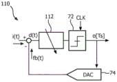
Fig. 9 shows an analog-to-digital converter 110 modified in accordance with the present invention. The analog input i (t) is filtered in filter 112 before being quantized in amplitude and time by a 1-bit analog-to-digital converter (also as in fig. 7) to generate a digital output o [ Ts ]. The feedback path includes a 1-bit digital-to-analog converter 74 and the analog feedback signal fb (t) is combined with the input to derive the difference signal d (t) that is supplied to the filter 112.
As explained above, in the general case, the ADC and DAC in a closed loop may be multi-bit.
The analog-to-digital converter may have a programmable clock frequency and DAC scalability.
The clock frequency may be adjusted to achieve the following benefits:
(i) which can be increased to increase resolution in the transition pass band by effectively increasing the over-sampling rate for that band,
(ii) which can be reduced to save power (thereby sacrificing some resolution when not needed),
(iii) it can also be used to tune the system. The system operation is a result of the loop filter's interaction with the clock frequency. When it is difficult to implement exact desired values for the loop filter coefficients, the overall desired performance can still be achieved by adjusting the clock frequency.
A fixed clock frequency may be preferable for a simplified implementation of the overall system.
If the clock frequency changes, the DAC can be rescaled to ensure the same DAC output with the new clock. Furthermore, the ADC may be scaled to accommodate different maximum input signals.
Most classical modes, such as the luminance mode (B-mode or 2D-mode) and the doppler mode, can use the proposed principles, which bring the benefit of only converting the desired bandwidth.
Further, harmonic imaging modes (e.g., for a given frequency) may be employed in which the same transducer array is used for transmit and receive. For example, the transmitter transmits signals with a low 1/3 of the frequency band of the transducer, while the receiver operates in the upper 1/3 of the frequency band to collect the third harmonic of the transmitted signal.
Furthermore, the transmission uses the full band of one low frequency transducer, while the receiver uses another high frequency transducer with a receive band positioned at the 3x higher frequency.
Fig. 10 shows the pass band of the filter 112 and the conversion band of the complete ADC. Region 120 shows a narrow band very high resolution mode, e.g., above 100dB with a bandwidth of 200 kHz. This enables very accurate amplitude measurements in a narrow frequency band for tissue characterization.
Thus, the band pass filter may be tunable between a low resolution high bandwidth mode and a high resolution low bandwidth mode. The high bandwidth mode for example has a passband in excess of 1MHz (e.g., in excess of 1.5MHz and possibly in excess of 3MHz), while the low/narrow bandwidth mode has a passband less than 1MHz (e.g., less than 750kHz, e.g., less than 500kHz and possibly less than 250 kHz). The y-axis in fig. 10 illustrates the achievable Dynamic Range (DR) of the complete a/D converter. Typically, the dynamic range is used to derive the resolution from the number of significant bits (ENOB). ENOB ═ SNR-1.76)/6.04, where in the ideal case SNR (signal-to-noise ratio) ═ DR.
The center frequency of the pass band is tuned to the transmit frequency or a harmonic of the transmit frequency. There are many options for transmitting the frequency. Typically, diagnostic imaging uses 2MHz to 5MHz, however for in vivo imaging with catheters, frequencies of 30MHz or higher may be used. For microvascular structures, higher frequencies may be used.
Adjusting the center frequency of the analog-to-digital converter is performed at the circuit level. The band-pass filter is implemented, for example, using a combination of active and passive circuits. These can be used to adapt the center frequency and the pass band of the filter to the various modes outlined above. These modes are also discussed below.
The narrow bandwidth mode for ultrasound acquisition below 1MHz may have a bandwidth as narrow as tens of kHz (e.g., 100 kHz). The corresponding high resolution refers to the Dynamic Range (DR) and signal-to-noise ratio (SNR) of the acquisition electronics. It is considered high resolution if it exceeds the value of classical B-mode imaging below the 12-bit significand (ENOB). The basic need for narrowband acquisition is driven by subtle differences between different tissues, which results in characteristic narrowband reflections that can only be analyzed with high accuracy and power efficiency with respect to narrowband signal acquisition. This mode is used for example for doppler imaging (continuous and pulsed).
The medium bandwidth mode is used, for example, for harmonic imaging, where the ADC center frequency is at a harmonic of the transmit frequency. The benefit of harmonic imaging is the fact that: as high frequency signals are more attenuated, more gain is required to acquire them. Applying the gain only for these frequencies would require analog pre-filtering in order to avoid clipping from the stronger low frequency signal. Analog filtering is typically expensive, either in terms of area or power.
The large bandwidth mode is used for B-mode or a-mode 2D and 3D imaging, for example. The bandwidth is set to match the bandwidth of the ADC transducer.
The three modes may be considered completely independent, but they may be used, for example, in sequence. Which mode to use will depend on the application or the measurement results within the application.
For example, in a pregnancy scan, B-mode imaging may be used for general imaging, while doppler imaging may be used for specific measurements of blood flow (e.g., in a fetal heart). Implementations that implement both modes in one ultrasound front end provide efficiency and cost savings. The tissue characterization may again be an entirely independent measurement that is used outside or inside the body for better characterization of tissue or tissue boundaries (e.g., use on a catheter).
The imaging procedure may thus include an initial use of B-mode imaging (large bandwidth lower resolution acquisition), which is then followed by harmonic imaging with higher resolution, and finally completed with the type of measurement of image acquisition with the greatest accuracy (as achievable in using narrowband mode). This is useful when data from the initial lower resolution imaging mode is used to guide a finer mode (e.g., by narrowing the volume that must be imaged with very high accuracy).
There are various ways to switch between modes. One method is for three modes to be performed sequentially and only a few parameters are needed to pass from one mode to another. Alternatively, the patterns may be staggered. For example, after scanning a small volume in B-mode, doppler or tissue characterization is used to evaluate the results deeper or provide input to subsequent B-mode acquisitions.
Fig. 11 shows a control circuit for controlling the pass band of the filter of the converter 110. The output of the filter is provided to DSP 130, and DSP 130 controls transducer controller 18. The synchronization signal from the transducer controller 18 is used to control the filter.
The DSP block 130 takes into account which signals have been used for transmission (frequency and bandwidth) and the desired imaging mode (which determines which frequency band must be converted). In this case, DSP 130 needs to tune the analog bandpass filter in the loop so that it is centered in the desired conversion bandwidth. There are known methods for how to tune the analog filter response using a fixed known frequency (e.g., the main frequency component of the transmit signal) as a reference.
The different modes of operation are achieved by design by introducing programmability of the filter coefficients (the unity gain frequency of the integrator and the values of the feedforward and feedback coefficients in the loop filter shown in the figure). The preferred way to implement programmability will depend on the design of the filter. In the case of the generally preferred active resistor-capacitor (RC) or transconductance-capacitor (Gm-C) filters, the coefficients are implemented by selecting appropriate values for the resistor, capacitor and transconductance values.
For example, for the topologies of fig. 12 and 13 (described below), the center frequency is determined by the unity gain frequency of the integrator and the local feedback path.
To change the center frequency of the filter to the desired harmonic, all coefficients should be scaled. Typically, for a fixed clock, all coefficients are scaled by the same pre-computed scaling factor N. Furthermore, for each coefficient, at least two values are implemented in hardware: nominal and N times nominal. For each new bandwidth, a new value of N must be used and the hardware enabled during implementation.
If all coefficients are scaled by the same factor N, the center frequency changes instead of the bandwidth. To also adjust the bandwidth, different poles in the transfer function h(s) are scaled by different factors. Furthermore, the scaling factor is pre-calculated and implemented in hardware.
This scaling can be used for fixed clocks as long as the center frequency of the transitions is less than fs/4(fs is the sampling frequency). This requirement is required in order to maintain the stability of the ADC. Furthermore, like poles, zeros of the transfer function h(s) (in the numerator of the transfer function) should be scaled by the same factor. The transmit frequency and its harmonics can thus be used for calibration of the nominal transfer function coefficients and the scaling factor N.
When this variable passband signal digitization is used in an ultrasound imaging system, a highly flexible and energy and area efficient construction is achieved.
The converter may be used in the system of fig. 3 with analog beamforming. However, if the digitization is performed very early in the signal processing chain before any beamforming, it enables various new options.
Specifically, the method then solves the following problems:
(i) analog-to-digital conversion over a wide frequency range of a few MHz is very expensive in terms of power and chip area. The cost is also highly dependent on the required resolution, so that a broadband high accuracy converter (>13ENOB) typically has a power consumption of several hundred mW. In the bandpass configuration, the power requirements decrease significantly as the conversion bandwidth decreases.
(ii) The bandpass sigma delta converter is very flexible and the acquisition front-end can be electronically tuned with several configuration bits to operate from a very narrow band mode (e.g. several kHz for CMUT based imaging) to full CMUT bandwidth. This can be achieved very quickly, even without adjustment of the CMUT bias voltage, thus increasing the reconfiguration speed and avoiding bias switching artifacts.
(iii) Bandpass acquisition naturally limits the amount of data since only the frequency range required by a particular imaging modality is actually acquired. The undesired noise band can be easily filtered with a simple digital filter. This further simplifies the requirements for the complete system and reduces its power consumption and cost.
In contrast to classical analog bandpass acquisitions, where analog bandpass filters are used, the proposed embodiment has the advantage of much higher speed. Analog bandpass filters are typically quite slow because they require a settling time for each successive signal acquisition. In a bandpass sigma delta converter, the stabilization process takes place at start-up, and during normal operation the built-in filter operates from a steady-state mode and thus reacts very quickly to input signal changes.
The embodiment is also much more stable. Analog bandpass filters are very prone to instability (especially high order filters) because they typically incorporate resonators with positive feedback or other filters. In a bandpass sigma delta architecture, stability is guaranteed via the existing negative feedback loop and filter construction can guarantee its stability.
The design is also more easily scalable and configurable. This stems from the introduction of several additional degrees of freedom, such as clock speed, DAC and quantizer programmability, which enables very wide configurability of the passband center frequency and bandwidth.
Filters may be used to achieve emission at one frequency and detection at another using electronic front-end reconfiguration.
The filter 112 may be implemented in various ways.
Fig. 12 shows an embodiment of the circuit of fig. 9 with a multi-level ADC 72 and DAC 74. The tunable bandpass filter 122 has a feedback structure in which an analog feedback signal is applied to the summing node of the structure through a first gain element 120 having a coefficient fx. A second gain element 122 with a coefficient gx is in the feedback path of the summing node. Between the nodes there is an integrator.
Fig. 13 shows an embodiment of the circuit of fig. 9, again with a multi-level ADC 72 and DAC 74. The tunable bandpass filter 112 has a feed-forward structure in which the analog feedback signal is supplied only to the first summing node of the structure. There is a feed forward gain element 130 with a coefficient fx leading to the last summing node. There is also a feedback gain element 132 with a coefficient gx that leads to the summing node of the structure. There is again an integrator between the nodes.
These are just two known examples of possible programmable band-pass filter structures that can be used within a converter. Other filter structures may also be employed.
The filter is programmable by making the fx and gx coefficients in the architecture programmable, as described above.
By way of example, the link between the controller 18 and the analog-to-digital converter 110 (fig. 11) may be a reference frequency signal that is used to adjust the fx and gx coefficients so that the frequency response of the filter is matched to the reference signal. This may be done, for example, by adjusting the coefficients until the filter response to the reference signal is maximized.
There may be more than one reference signal from the controller 18 to the converter 110. The signal may be static for switching the filter to a pre-programmed known state, or it may be used to adapt the filter to a reference signal. The reference signal may be a time variable. The simplest implementation may have all modes implemented in hardware at the design. The controller can then switch between modes and only calibrate if needed.
Other variations to the disclosed embodiments can be understood and effected by those skilled in the art in practicing the claimed invention, from a study of the drawings, the disclosure, and the appended claims. In the claims, the word "comprising" does not exclude other elements or steps, and the word "a" or "an" does not exclude a plurality. The mere fact that certain measures are recited in mutually different dependent claims does not indicate that a combination of these measures cannot be used to advantage. Any reference signs in the claims should not be construed as limiting the scope.
Claims (13)
1. An ultrasound imaging system probe, comprising:
an imaging transducer head (10') arranged to emit ultrasound signals at an emission ultrasound frequency; and
a receiving circuit for processing the received reflected ultrasonic signal,
wherein the receiving circuit comprises an analog-to-digital sigma delta converter (110) comprising a closed loop comprising a tunable bandpass filter (112) having a programmable center frequency and bandwidth, and
wherein a center of a pass band of the tunable bandpass filter (112) is tunable between a first frequency corresponding to the transmit ultrasonic frequency and a second frequency corresponding to a desired harmonic of the transmit ultrasonic frequency.
2. The probe of claim 1, wherein the transducer head (10') comprises an array of transducer elements, and wherein the receiving circuitry comprises an analog-to-digital sigma delta converter for each transducer element of the transducer head.
3. The probe according to claim 2, wherein the receiving circuit comprises an amplifier (20) between each transducer element and a respective analog-to-digital sigma delta converter.
4. A probe according to any preceding claim wherein the band pass filter is tunable between a low resolution high bandwidth mode and a high resolution low bandwidth mode.
5. The probe of claim 4, wherein the band pass filter is further tunable to a medium resolution medium bandwidth mode.
6. An ultrasound system, comprising:
an ultrasound imaging system probe according to any preceding claim;
a controller (18) for controlling the probe;
a beam former; and
a signal processing circuit for processing signals from the receive circuit to generate an ultrasound image.
7. The system of claim 6, wherein the controller is adapted to control the tunable bandpass filter in synchronization with switching between different receive modes of operation of the ultrasound system.
8. The system of claim 6 or 7, wherein the receive circuitry is to process a received reflected ultrasound signal that is a harmonic of the transmitted ultrasound signal.
9. An ultrasound imaging method comprising:
providing ultrasound signals into a volume to be imaged using an imaging transducer head; and is
Processing the received reflected ultrasonic signal by tuning a band-pass filter within a closed loop of an analog-to-digital sigma-delta converter, the band-pass filter having a programmable center frequency and bandwidth,
wherein the method comprises setting a center of a passband of the tunable bandpass filter to a transmit ultrasonic frequency or a desired harmonic of the transmit ultrasonic frequency.
10. The method of claim 9, wherein the transducer head comprises an array of transducer elements, and wherein the method comprises performing analog-to-digital conversion individually for each transducer element of the transducer head.
11. A method according to claim 9 or 10, comprising tuning the band pass filter in synchronism with switching between different receive modes of operation.
12. The method of claim 11, wherein the modes include a low resolution high bandwidth mode and a high resolution low bandwidth mode.
13. The method of claim 12, wherein the modes further comprise a medium resolution medium bandwidth mode.
Applications Claiming Priority (3)
| Application Number | Priority Date | Filing Date | Title |
|---|---|---|---|
| EP15198841 | 2015-12-10 | ||
| EP15198841.7 | 2015-12-10 | ||
| PCT/EP2016/080409 WO2017097968A1 (en) | 2015-12-10 | 2016-12-09 | An ultrasound imaging system probe and system, and an imaging method |
Publications (2)
| Publication Number | Publication Date |
|---|---|
| CN108463173A CN108463173A (en) | 2018-08-28 |
| CN108463173B true CN108463173B (en) | 2021-09-21 |
Family
ID=54848438
Family Applications (1)
| Application Number | Title | Priority Date | Filing Date |
|---|---|---|---|
| CN201680078538.1A Active CN108463173B (en) | 2015-12-10 | 2016-12-09 | Ultrasonic imaging system probe and system and imaging method |
Country Status (6)
| Country | Link |
|---|---|
| US (1) | US11506770B2 (en) |
| EP (1) | EP3386394A1 (en) |
| JP (1) | JP6797919B2 (en) |
| CN (1) | CN108463173B (en) |
| RU (1) | RU2734129C2 (en) |
| WO (1) | WO2017097968A1 (en) |
Families Citing this family (9)
| Publication number | Priority date | Publication date | Assignee | Title |
|---|---|---|---|---|
| US10857567B2 (en) | 2017-06-20 | 2020-12-08 | Butterfly Network, Inc. | Analog to digital signal conversion in ultrasound device |
| EP3435116A1 (en) * | 2017-07-24 | 2019-01-30 | Koninklijke Philips N.V. | An ultrasound probe and processing method |
| TWI743411B (en) * | 2017-11-08 | 2021-10-21 | 美商富士膠片索諾聲公司 | Ultrasound system with high frequency detail |
| CN108051501A (en) * | 2018-01-08 | 2018-05-18 | 飞依诺科技(苏州)有限公司 | Front end receiver device and ultrasonic system |
| WO2019185633A1 (en) | 2018-03-27 | 2019-10-03 | Koninklijke Philips N.V. | Systems and methods for performing analog-to-digital conversion across multiple, spatially separated stages |
| US10804942B2 (en) * | 2018-05-24 | 2020-10-13 | Analog Devices, Inc. | State-machine based body scanner imaging system |
| US20210169455A1 (en) * | 2019-12-04 | 2021-06-10 | GE Precision Healthcare LLC | System and methods for joint scan parameter selection |
| RU2757097C2 (en) * | 2020-02-07 | 2021-10-11 | Тимофей Андреевич Семенюк | Means for blocking radio-controlled fuses |
| RU2766424C2 (en) * | 2020-02-07 | 2022-03-15 | Тимофей Андреевич Семенюк | Antenna system for mobile radio jamming devices |
Citations (4)
| Publication number | Priority date | Publication date | Assignee | Title |
|---|---|---|---|---|
| CN1169219A (en) * | 1995-11-21 | 1997-12-31 | 菲利浦电子有限公司 | Digital transmission system for transmitting digital audio signal being in form of samples of a specific wordlength and occurring at specific sampling rate |
| JP2007260394A (en) * | 2006-03-29 | 2007-10-11 | Medison Co Ltd | Receiving and focusing device using sigma-delta analogue-digital converter in ultrasonic system |
| CN104135912A (en) * | 2012-02-29 | 2014-11-05 | 通用电气公司 | System and method for determining physiological parameters based on electrical impedance measurements |
| CN105122077A (en) * | 2013-04-09 | 2015-12-02 | 皇家飞利浦有限公司 | Radio frequency antenna device for generating a digital magnetic resonance information signal |
Family Cites Families (32)
| Publication number | Priority date | Publication date | Assignee | Title |
|---|---|---|---|---|
| US4691571A (en) * | 1985-03-04 | 1987-09-08 | Dymax Corporation | Tissue signature tracking transceiver having upconverted IF amplification |
| FR2707815B1 (en) | 1993-07-13 | 1995-08-25 | Alcatel Mobile Comm France | Analog to digital converter with modulated feedback loop. |
| US8085959B2 (en) * | 1994-07-08 | 2011-12-27 | Brigham Young University | Hearing compensation system incorporating signal processing techniques |
| JP3580627B2 (en) * | 1996-01-29 | 2004-10-27 | 株式会社東芝 | Ultrasound diagnostic equipment |
| US6544193B2 (en) * | 1996-09-04 | 2003-04-08 | Marcio Marc Abreu | Noninvasive measurement of chemical substances |
| US6283919B1 (en) | 1996-11-26 | 2001-09-04 | Atl Ultrasound | Ultrasonic diagnostic imaging with blended tissue harmonic signals |
| US6458083B1 (en) | 1996-11-26 | 2002-10-01 | Koninklijke Philips Electronics N.V. | Ultrasonic harmonic imaging with adaptive image formation |
| US6107910A (en) * | 1996-11-29 | 2000-08-22 | X-Cyte, Inc. | Dual mode transmitter/receiver and decoder for RF transponder tags |
| US6218972B1 (en) | 1997-09-11 | 2001-04-17 | Rockwell Science Center, Inc. | Tunable bandpass sigma-delta digital receiver |
| US6013032A (en) | 1998-03-13 | 2000-01-11 | Hewlett-Packard Company | Beamforming methods and apparatus for three-dimensional ultrasound imaging using two-dimensional transducer array |
| US5997479A (en) | 1998-05-28 | 1999-12-07 | Hewlett-Packard Company | Phased array acoustic systems with intra-group processors |
| US6419632B1 (en) * | 1999-03-30 | 2002-07-16 | Kabushiki Kaisha Toshiba | High resolution flow imaging for ultrasound diagnosis |
| US6530885B1 (en) | 2000-03-17 | 2003-03-11 | Atl Ultrasound, Inc. | Spatially compounded three dimensional ultrasonic images |
| US6443896B1 (en) * | 2000-08-17 | 2002-09-03 | Koninklijke Philips Electronics N.V. | Method for creating multiplanar ultrasonic images of a three dimensional object |
| US6468216B1 (en) | 2000-08-24 | 2002-10-22 | Kininklijke Philips Electronics N.V. | Ultrasonic diagnostic imaging of the coronary arteries |
| US6693573B1 (en) | 2003-03-19 | 2004-02-17 | Raytheon Company | Mixed technology MEMS/BiCMOS LC bandpass sigma-delta for direct RF sampling |
| JP4087762B2 (en) * | 2003-07-24 | 2008-05-21 | アロカ株式会社 | Ultrasonic diagnostic equipment |
| US6937176B2 (en) * | 2003-09-30 | 2005-08-30 | Koninklijke Philips Electronics, N.V. | Ultrasonic signal acquisition in the digital beamformer |
| US20050251041A1 (en) | 2004-05-07 | 2005-11-10 | Moehring Mark A | Doppler ultrasound processing system and method for concurrent acquisition of ultrasound signals at multiple carrier frequencies, embolus characterization system and method, and ultrasound transducer |
| DE102005003630A1 (en) | 2005-01-26 | 2006-07-27 | Robert Bosch Gmbh | Electromechanical delta-sigma-modulator for e.g. airbag control system of motor vehicle, has multibit-DAC to adjust amplification in servo loop and bandwidth of modulator independent of input signal of multibit-ADC |
| US8355776B2 (en) * | 2005-05-27 | 2013-01-15 | Board Of Regents, The University Of Texas System | Hemoglobin contrast in magneto-motive optical doppler tomography, optical coherence tomography, and ultrasound imaging methods and apparatus |
| JP4728756B2 (en) * | 2005-09-22 | 2011-07-20 | 株式会社東芝 | Ultrasonic diagnostic equipment |
| CN101360455B (en) * | 2006-03-24 | 2011-08-24 | 株式会社日立医药 | Ultrasound imaging device |
| US8220334B2 (en) * | 2006-11-10 | 2012-07-17 | Penrith Corporation | Transducer array imaging system |
| US20090082673A1 (en) * | 2007-09-26 | 2009-03-26 | Xuanming Lu | Semiconductor matching layer in a layered ultrasound transducer array |
| JP5538822B2 (en) * | 2009-11-06 | 2014-07-02 | キヤノン株式会社 | Ultrasonic detection device and ultrasonic diagnostic device |
| US9289191B2 (en) * | 2011-10-12 | 2016-03-22 | Seno Medical Instruments, Inc. | System and method for acquiring optoacoustic data and producing parametric maps thereof |
| US9814394B2 (en) * | 2011-11-02 | 2017-11-14 | Seno Medical Instruments, Inc. | Noise suppression in an optoacoustic system |
| US20130116538A1 (en) * | 2011-11-02 | 2013-05-09 | Seno Medical Instruments, Inc. | Optoacoustic imaging systems and methods with enhanced safety |
| US9445786B2 (en) * | 2011-11-02 | 2016-09-20 | Seno Medical Instruments, Inc. | Interframe energy normalization in an optoacoustic imaging system |
| WO2015028945A2 (en) | 2013-08-27 | 2015-03-05 | Koninklijke Philips N.V. | Variable frequency control of collapsed mode cmut transducer |
| WO2016164900A1 (en) * | 2015-04-09 | 2016-10-13 | The General Hospital Corporation | Systems and methods for time-resolved diffuse correlation spectroscopy |
-
2016
- 2016-12-09 RU RU2018124990A patent/RU2734129C2/en active
- 2016-12-09 WO PCT/EP2016/080409 patent/WO2017097968A1/en active Application Filing
- 2016-12-09 US US15/780,250 patent/US11506770B2/en active Active
- 2016-12-09 JP JP2018529996A patent/JP6797919B2/en active Active
- 2016-12-09 CN CN201680078538.1A patent/CN108463173B/en active Active
- 2016-12-09 EP EP16812714.0A patent/EP3386394A1/en active Pending
Patent Citations (4)
| Publication number | Priority date | Publication date | Assignee | Title |
|---|---|---|---|---|
| CN1169219A (en) * | 1995-11-21 | 1997-12-31 | 菲利浦电子有限公司 | Digital transmission system for transmitting digital audio signal being in form of samples of a specific wordlength and occurring at specific sampling rate |
| JP2007260394A (en) * | 2006-03-29 | 2007-10-11 | Medison Co Ltd | Receiving and focusing device using sigma-delta analogue-digital converter in ultrasonic system |
| CN104135912A (en) * | 2012-02-29 | 2014-11-05 | 通用电气公司 | System and method for determining physiological parameters based on electrical impedance measurements |
| CN105122077A (en) * | 2013-04-09 | 2015-12-02 | 皇家飞利浦有限公司 | Radio frequency antenna device for generating a digital magnetic resonance information signal |
Non-Patent Citations (1)
| Title |
|---|
| A 1.8 V CMOS fourth-order Gm-C bandpass sigma-delta modulator dedicated to front-end ultrasonic receivers;Lisheng Qin 等;《ANALOG INTEGRATED CIRCUITS AND SIGNAL PROCESSING》;20060509;第48卷(第2期);第121-132页 * |
Also Published As
| Publication number | Publication date |
|---|---|
| RU2018124990A3 (en) | 2020-04-24 |
| JP2018536498A (en) | 2018-12-13 |
| RU2018124990A (en) | 2020-01-10 |
| US20180348349A1 (en) | 2018-12-06 |
| RU2734129C2 (en) | 2020-10-13 |
| CN108463173A (en) | 2018-08-28 |
| WO2017097968A1 (en) | 2017-06-15 |
| EP3386394A1 (en) | 2018-10-17 |
| JP6797919B2 (en) | 2020-12-09 |
| US11506770B2 (en) | 2022-11-22 |
Similar Documents
| Publication | Publication Date | Title |
|---|---|---|
| CN108463173B (en) | Ultrasonic imaging system probe and system and imaging method | |
| JP5575907B2 (en) | Ultrasonic probe and ultrasonic diagnostic apparatus | |
| EP3132281B1 (en) | Ultrasonic imaging compression methods and apparatus | |
| Brunner | Ultrasound system considerations and their impact on front-end components | |
| JP4931386B2 (en) | Method and apparatus for performing CW Doppler ultrasound using a 2D matrix array | |
| EP3248027B1 (en) | Systems and methods for beamforming using variable sampling | |
| JP4825625B2 (en) | Ultrasonic diagnostic equipment | |
| WO2000010638A2 (en) | An asynchronous oversampling beamformer | |
| KR20160030753A (en) | Transmit beamforming apparatus, receive beamforming apparatus, ultrasound probe having the same, and method for beamforming | |
| Wagner et al. | Compressed beamforming applied to B-mode ultrasound imaging | |
| JP4728756B2 (en) | Ultrasonic diagnostic equipment | |
| WO2004082461A2 (en) | Increased sensitivity for 4-d doppler ultrasound imaging | |
| JP6838174B2 (en) | Ultrasonic probe and processing method | |
| JP5468468B2 (en) | Ultrasonic diagnostic equipment | |
| Daft et al. | 5F-3 A Matrix Transducer Design with Improved Image Quality and Acquisition Rate | |
| US20240045044A1 (en) | Digitizing asic for an ultrasound scanning unit | |
| Tomov et al. | A Delta-Sigma beamformer with integrated apodization | |
| JP2008161262A (en) | Ultrasonic diagnostic apparatus | |
| LIE et al. | Optimizing the cost to quality ratio in ultrasonic imaging | |
| Abu-Bakr et al. | Implementation of a Pulsed-Wave Spectral Doppler Module on a Programmable Ultrasound System | |
| KR20230152117A (en) | Acoustic imaging and measurements using windowed nonlinear frequency modulated chirps | |
| Cheong et al. | Multi-bit sigma-delta beamformer with minimal dynamic focusing artifacts | |
| Gao | Efficient digital beamforming for medical ultrasound imaging |
Legal Events
| Date | Code | Title | Description |
|---|---|---|---|
| PB01 | Publication | ||
| PB01 | Publication | ||
| SE01 | Entry into force of request for substantive examination | ||
| SE01 | Entry into force of request for substantive examination | ||
| GR01 | Patent grant | ||
| GR01 | Patent grant |