CN108449299B - Method and arrangement for communication in a low power wireless network - Google Patents
Method and arrangement for communication in a low power wireless network Download PDFInfo
- Publication number
- CN108449299B CN108449299B CN201810204542.9A CN201810204542A CN108449299B CN 108449299 B CN108449299 B CN 108449299B CN 201810204542 A CN201810204542 A CN 201810204542A CN 108449299 B CN108449299 B CN 108449299B
- Authority
- CN
- China
- Prior art keywords
- subcarriers
- coding rate
- data
- ofdm
- bits
- Prior art date
- Legal status (The legal status is an assumption and is not a legal conclusion. Google has not performed a legal analysis and makes no representation as to the accuracy of the status listed.)
- Active
Links
Images

Classifications
-
- H—ELECTRICITY
- H04—ELECTRIC COMMUNICATION TECHNIQUE
- H04L—TRANSMISSION OF DIGITAL INFORMATION, e.g. TELEGRAPHIC COMMUNICATION
- H04L27/00—Modulated-carrier systems
- H04L27/26—Systems using multi-frequency codes
- H04L27/2601—Multicarrier modulation systems
- H04L27/2602—Signal structure
-
- H—ELECTRICITY
- H04—ELECTRIC COMMUNICATION TECHNIQUE
- H04B—TRANSMISSION
- H04B7/00—Radio transmission systems, i.e. using radiation field
- H04B7/02—Diversity systems; Multi-antenna system, i.e. transmission or reception using multiple antennas
- H04B7/04—Diversity systems; Multi-antenna system, i.e. transmission or reception using multiple antennas using two or more spaced independent antennas
- H04B7/06—Diversity systems; Multi-antenna system, i.e. transmission or reception using multiple antennas using two or more spaced independent antennas at the transmitting station
- H04B7/0697—Diversity systems; Multi-antenna system, i.e. transmission or reception using multiple antennas using two or more spaced independent antennas at the transmitting station using spatial multiplexing
-
- H—ELECTRICITY
- H04—ELECTRIC COMMUNICATION TECHNIQUE
- H04L—TRANSMISSION OF DIGITAL INFORMATION, e.g. TELEGRAPHIC COMMUNICATION
- H04L1/00—Arrangements for detecting or preventing errors in the information received
-
- H—ELECTRICITY
- H04—ELECTRIC COMMUNICATION TECHNIQUE
- H04L—TRANSMISSION OF DIGITAL INFORMATION, e.g. TELEGRAPHIC COMMUNICATION
- H04L27/00—Modulated-carrier systems
- H04L27/0008—Modulated-carrier systems arrangements for allowing a transmitter or receiver to use more than one type of modulation
-
- H—ELECTRICITY
- H04—ELECTRIC COMMUNICATION TECHNIQUE
- H04L—TRANSMISSION OF DIGITAL INFORMATION, e.g. TELEGRAPHIC COMMUNICATION
- H04L27/00—Modulated-carrier systems
- H04L27/10—Frequency-modulated carrier systems, i.e. using frequency-shift keying
- H04L27/12—Modulator circuits; Transmitter circuits
-
- H—ELECTRICITY
- H04—ELECTRIC COMMUNICATION TECHNIQUE
- H04L—TRANSMISSION OF DIGITAL INFORMATION, e.g. TELEGRAPHIC COMMUNICATION
- H04L27/00—Modulated-carrier systems
- H04L27/26—Systems using multi-frequency codes
- H04L27/2601—Multicarrier modulation systems
- H04L27/2626—Arrangements specific to the transmitter only
- H04L27/2627—Modulators
- H04L27/2628—Inverse Fourier transform modulators, e.g. inverse fast Fourier transform [IFFT] or inverse discrete Fourier transform [IDFT] modulators
-
- H—ELECTRICITY
- H04—ELECTRIC COMMUNICATION TECHNIQUE
- H04L—TRANSMISSION OF DIGITAL INFORMATION, e.g. TELEGRAPHIC COMMUNICATION
- H04L5/00—Arrangements affording multiple use of the transmission path
- H04L5/0001—Arrangements for dividing the transmission path
- H04L5/0014—Three-dimensional division
- H04L5/0023—Time-frequency-space
-
- H—ELECTRICITY
- H04—ELECTRIC COMMUNICATION TECHNIQUE
- H04L—TRANSMISSION OF DIGITAL INFORMATION, e.g. TELEGRAPHIC COMMUNICATION
- H04L5/00—Arrangements affording multiple use of the transmission path
- H04L5/003—Arrangements for allocating sub-channels of the transmission path
- H04L5/0044—Arrangements for allocating sub-channels of the transmission path allocation of payload
-
- H—ELECTRICITY
- H04—ELECTRIC COMMUNICATION TECHNIQUE
- H04L—TRANSMISSION OF DIGITAL INFORMATION, e.g. TELEGRAPHIC COMMUNICATION
- H04L5/00—Arrangements affording multiple use of the transmission path
- H04L5/003—Arrangements for allocating sub-channels of the transmission path
- H04L5/0048—Allocation of pilot signals, i.e. of signals known to the receiver
-
- H—ELECTRICITY
- H04—ELECTRIC COMMUNICATION TECHNIQUE
- H04L—TRANSMISSION OF DIGITAL INFORMATION, e.g. TELEGRAPHIC COMMUNICATION
- H04L5/00—Arrangements affording multiple use of the transmission path
- H04L5/003—Arrangements for allocating sub-channels of the transmission path
- H04L5/0058—Allocation criteria
- H04L5/0064—Rate requirement of the data, e.g. scalable bandwidth, data priority
-
- H—ELECTRICITY
- H04—ELECTRIC COMMUNICATION TECHNIQUE
- H04L—TRANSMISSION OF DIGITAL INFORMATION, e.g. TELEGRAPHIC COMMUNICATION
- H04L27/00—Modulated-carrier systems
- H04L27/26—Systems using multi-frequency codes
- H04L27/2601—Multicarrier modulation systems
- H04L27/2602—Signal structure
- H04L27/26025—Numerology, i.e. varying one or more of symbol duration, subcarrier spacing, Fourier transform size, sampling rate or down-clocking
Landscapes
- Engineering & Computer Science (AREA)
- Signal Processing (AREA)
- Computer Networks & Wireless Communication (AREA)
- Physics & Mathematics (AREA)
- Discrete Mathematics (AREA)
- General Physics & Mathematics (AREA)
- Mathematical Physics (AREA)
- Mobile Radio Communication Systems (AREA)
- Digital Transmission Methods That Use Modulated Carrier Waves (AREA)
- Radio Transmission System (AREA)
Abstract
The title of the invention of the present disclosure is "method and arrangement for communication in a low power wireless network". Embodiments may include Orthogonal Frequency Division Multiplexing (OFDM) systems operating in the 1GHz and lower frequency bands. In many embodiments, the physical layer logic may implement orthogonal frequency division multiplexing symbols encoded with 32 subcarriers, e.g., twenty data subcarriers, four pilot subcarriers, seven guard subcarriers, and one Direct Current (DC) subcarrier. Many embodiments may transform the orthogonal frequency division multiplexing symbols between the frequency domain and the time domain with a 32-point fast fourier transform or an inverse fast fourier transform. Some embodiments may up-convert and transmit a communication signal having orthogonal frequency division multiplexing symbols at one megahertz. Further embodiments may receive and detect a communication signal having orthogonal frequency division multiplexing symbols at one megahertz.
Description
Technical Field
Embodiments are in the field of wireless communications. More particularly, embodiments are in the field of communication protocols between wireless transmitters and receivers.
Drawings
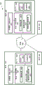
Fig. 1 depicts an embodiment of an example wireless network including multiple communication devices (including multiple fixed or mobile communication devices);
1A-1D depict alternative embodiments of OFDM symbols for 1MHz operation of the transceiver in FIG. 1;
fig. 2 depicts an embodiment of an apparatus for generating and transmitting Orthogonal Frequency Division Multiplexing (OFDM) -based communications in a wireless network;
2A-2D depict alternative embodiments of tables with row and column parameters for interleaving data in 1MHz operation of the transceiver in FIG. 2;
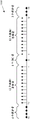
fig. 3 depicts an embodiment of a flow diagram for transmitting communications with a transmitter as illustrated in fig. 2; and
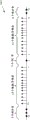
fig. 4 depicts an embodiment of a flow diagram for receiving communications with a receiver as illustrated in fig. 2.
Detailed Description
The following is a detailed description of novel embodiments depicted in the accompanying drawings. However, the amount of detail offered is not intended to limit the anticipated variations of the described embodiments; on the contrary, the claims and detailed description are to cover all modifications, equivalents, and alternatives falling within the spirit and scope of the present teachings as defined by the appended claims. The detailed description that follows is designed to enable such embodiments to be understood by those having ordinary skill in the art.
Embodiments may include Orthogonal Frequency Division Multiplexing (OFDM) systems operating at 1GHz and lower frequency bands. In the frequency bands of 1GHz and below, the available bandwidth is limited, so IEEE 802.11n/ac type systems using 20, 40, 80 and 160MHz bandwidths may not be feasible in some geographical areas. In many embodiments, the system has a bandwidth on the order of approximately 1 to 10 MHz. In several embodiments, 802.11n/ac type systems may be clocked down at a slower rate to achieve a lower bandwidth. For example, many embodiments may be reduced in clock rate by 1/N, such as 20, 40, 80, and 160MHz divided by N, where N may assume a value of, for example, 10, thereby providing 2, 4, 8, and 16MHz bandwidth operation. Embodiments may also implement a 1MHz bandwidth by another method. In some embodiments, tone counts for 2, 4, 8, and 16MHz bandwidths may be based on those in IEEE 802.11ac systems. In other embodiments, the tone count may be different from those of IEEE 802.11ac systems, eliminating tone counts that are not redundant at lower bandwidths, for example.
In many embodiments, the physical layer logic may implement a particular tone count for 1MHz operation. For example, in 1MHz operation, an orthogonal frequency division multiplexing symbol may include twenty data subcarriers (tones), four pilot subcarriers, seven guard subcarriers, and one Direct Current (DC) subcarrier. In other embodiments, the orthogonal frequency division multiplexing symbol may include twenty-four data subcarriers (tones), two pilot subcarriers, five guard subcarriers, and one Direct Current (DC) subcarrier. In other embodiments, the orthogonal frequency division multiplexing symbol may include twenty-two data subcarriers (tones), four pilot subcarriers, five guard subcarriers, and one Direct Current (DC) subcarrier. In still other embodiments, the orthogonal frequency division multiplexing symbol may include twenty-two data subcarriers (tones), two pilot subcarriers, seven guard subcarriers, and one Direct Current (DC) subcarrier.
Such an embodiment may transform the orthogonal frequency division multiplexing symbols with a 32-point fast fourier transform or inverse fast fourier transform between the frequency and time domains. Some embodiments may up-convert and transmit a communication signal having orthogonal frequency division multiplexing symbols at one megahertz. Further embodiments may receive and detect a communication signal having orthogonal frequency division multiplexing symbols at one megahertz.
Some embodiments may provide, for example, indoor and/or outdoor "smart" power grids and sensor services. For example, some embodiments may provide sensors to meter the use of electricity, water, gas, and/or other utilities to a home or homes within a particular area and wirelessly transmit the use of these services to a meter substation. Further embodiments may utilize sensors for home healthcare, clinics or hospitals for monitoring patients for healthcare related events and vital signs, such as fall detection, vial monitoring, weight monitoring, sleep apnea, blood glucose levels, heart rhythm and the like. Embodiments designed for such services generally require much lower data rates and much lower (ultra-low) power consumption than the devices provided in IEEE 802.11n/ac systems.
Some embodiments reuse IEEE 802.11n/ac systems with new features that meet these lower data rate and ultra-low power consumption requirements to reuse hardware implementations and reduce implementation costs. Further embodiments accommodate multiple streams. Several embodiments do not implement legacy training fields and legacy signatures and do not implement multi-user multiple-input multiple-output (MIMO). And some embodiments employ beamforming.
The logic, modules, devices, and interfaces described herein may perform functions that may be implemented in hardware and/or code. The hardware and/or code may comprise software, firmware, microcode, processors, state machines, chipsets, or combinations thereof, designed to perform the functionality.
Embodiments may facilitate wireless communication. Some embodiments may integrate low power wireless communications like Bluetooth @, Wireless Local Area Network (WLAN), Wireless Metropolitan Area Network (WMAN), Wireless Personal Area Network (WPAN), cellular network, and/or Institute of Electrical and Electronics Engineers (IEEE) IEEE 802.11-2007 (Telecommunications and information exchange between IEEE standards of information technology-local and metropolitan area networks-specific requirements-part 11: Wireless LAN Medium Access Control (MAC) and physical layer (PHY) specifications: (A)http://standards.ieee.org/getieee802/download/802.11-2007.pdf) In networks, messaging systems, and smart devices) for facilitating interaction between such devices. Furthermore, some wireless embodiments may include a single antenna, while other embodiments may employ multiple antennas.
Turning now to fig. 1, an embodiment of a wireless communication system 1000 is shown. The wireless communication system 1000 includes a communication device 1010 that is either wired or wirelessly connected to a network 1005. The communication device 1010 may wirelessly communicate with a plurality of communication devices 1030, 1050, and 1055 via a network 1005. These communication devices 1010, 1030, 1050, and 1055 may include sensors, stations, access points, hubs, switches, routers, computers, laptops, notebooks, cell phones, PDAs (personal digital assistants), or other wireless-capable devices. Thus, the communication device may be mobile or stationary. For example, the communication device 1010 may include a metering substation for water consumption within a home community. Each of the households within the community may include a communication device such as communication device 1030 and communication device 1030 may be integrated with or coupled to a water meter usage meter. The communication device 1030 may periodically initiate communication with the metering substation to transmit data related to water usage over a 1MHz bandwidth channel. Communications device 1030 may create a communication signal by encoding symbols with twenty data subcarriers, four pilot subcarriers, seven guard subcarriers, and one dc subcarrier and transforming the symbols from the frequency domain to the time domain. Further, a metering station or other communication device may periodically initiate communication with the communication device 1030 over a 1MHz bandwidth channel, interleaving symbols having five columns by 4 times Nbpscs (N bits per single encoded symbol), for example, to update the firmware of the communication device 1030. In other embodiments, communications device 1030 may only respond to communications and may not include logic to initiate communications.
In other embodiments, communications device 1030 may create a communication signal by encoding symbols with twenty-four data subcarriers (tones), two pilot subcarriers, five guard subcarriers, and one Direct Current (DC) subcarrier and transforming the symbols from the frequency domain to the time domain. In other embodiments, communications device 1030 may encode symbols with twenty-two data subcarriers (tones), four pilot subcarriers, five guard subcarriers, and one Direct Current (DC) subcarrier and transform the symbols from the frequency domain to the time domain to create a communication signal. In still other embodiments, communications device 1030 may encode symbols with twenty-two data subcarriers (tones), two pilot subcarriers, seven guard subcarriers, and one Direct Current (DC) subcarrier and transform the symbols from the frequency domain to the time domain to create a communication signal.
In further embodiments, the communication device 1010 may facilitate data offloading. For example, a communication device that is a low power sensor may include a data offload scheme for communication, e.g., via Wi-Fi, another communication device, a cellular network, or the like, for the purpose of reducing power consumption and/or improving bandwidth availability consumed while waiting to access, e.g., a metering station. The communication devices receiving data from sensors, such as metering stations, may include data offloading schemes for communicating, for example, via Wi-Fi, another communication device, a cellular network, or the like for purposes of reducing congestion of the network 1005.
Network 1005 may represent an interconnection of many networks. For example, the network 1005 may be coupled with a wide area network or an intranet, such as the internet, and may interconnect local devices that are interconnected, either wired or wirelessly, via one or more hubs, routers, or switches. In this embodiment, a network 1005 communicatively couples communication devices 1010, 1030, 1050, and 1055.
Communication devices 1010 and 1030 include memories 1011 and 1031, respectively, and Media Access Control (MAC) sublayer logic 1018 and 1038, respectively. Memories 1011, 1031, such as Dynamic Random Access Memories (DRAMs), may store frames, preambles and preamble structures or portions thereof. The frame (also referred to as a MAC layer protocol data unit (MPDU)) and preamble structure may establish and maintain synchronous communication between the transmitting device and the receiving device.
MAC sublayer logic 1018, 1038 may generate frames and physical layer logic 1019, 1039 may generate physical layer data units (PPDUs). More specifically, frame constructors 1012 and 1032 may generate frames and data unit constructors 1013 and 1033 may generate PPDUs. Data unit constructors 1013 and 1033 may generate PPDUs for transmission over one or more RF channels via antenna arrays 1024 and 1044, respectively, by encapsulating payloads including frames generated by frame constructors 1012 and 1032 to prefix the payloads.
Communications devices 1010, 1030, 1050, and 1055 may each include a transceiver (RX/TX), such as transceivers (RX/TX) 1020 and 1040. In many embodiments, transceivers 1020 and 1040 implement Orthogonal Frequency Division Multiplexing (OFDM). OFDM is a method of encoding digital data on multiple carrier frequencies. OFDM is a frequency division multiplexing scheme used as a digital multi-carrier modulation method. A large number of closely spaced orthogonal subcarrier signals are used to convey the data as OFDM symbols. The OFDM symbol is divided into several parallel data streams or channels (one for each subcarrier) and encoded with subcarriers (e.g., twenty data subcarriers, seven guard subcarriers, four pilot subcarriers, and one DC subcarrier), thereby transmitting the OFDM symbol to a receiving device. Each subcarrier is modulated with a modulation scheme at a low symbol rate to maintain an overall data rate similar to a conventional single carrier modulation scheme in the same bandwidth.
OFDM systems use several carriers or "tones" for functions including data, pilot, guard, and nulling. The data tones are used to transmit information between the transmitter and the receiver via one of the channels. The pilot tones are used to maintain the channel and may provide information about time/frequency and channel tracking. Guard tones may be inserted between symbols, such as Short Training Field (STF) and Long Training Field (LTF) symbols, during transmission to avoid inter-symbol interference (ISI), which may result from multipath distortion. These guard tones also help the signal to follow spectral masking. Zeroing of the direct current component (DC) can be used to simplify the direct conversion receiver design.
Each transceiver 1020, 1040 includes an RF transmitter and an RF receiver. The RF transmitter includes an OFDM module 1022 that impresses digital data (tone-coded OFDM symbols) on RF frequencies (also referred to as subcarriers) for transmitting the data by electromagnetic radiation. In this embodiment, the OFDM module 1022 may append digital data, which is tone-coded OFDM symbols, onto the subcarriers for transmission. For a 1MHz bandwidth, an OFDM symbol may include 20 data tones, seven guard tones, four pilot tones, and one DC tone in some embodiments. In further embodiments, the OFDM symbol may include: 24 data tones, two pilot tones, five guard tones, and one DC tone; 22 data tones, four pilot tones, five guard tones, and one DC tone; or 22 data tones, two pilot tones, seven guard tones, and one DC tone.
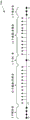
Fig. 1A illustrates an embodiment of an OFDM symbol 1060. For a transceiver (corresponding to a 32-point inverse fourier transform), such as the transceiver of fig. 1, OFDM module 1022 may generate different OFDM symbols for different bandwidths, such as 2MHz, 4MHz, 8MHz, and 16MHz and may generate OFDM symbols 1060 for 1MHz bandwidth channels. The OFDM symbol 1060 includes 32 tones (also referred to as subcarriers) indexed from-16 to 15. The 32 tones include 20 data tones, seven guard tones, four pilot tones, and a Direct Current (DC) tone. The four lowest frequency tones are guard tones provided for filter ramp up and filter ramp down. The indexed zero frequency tone is a DC tone and is provided to mitigate radio frequency interference. The DC tone may include tones at a carrier frequency (e.g., 1 MHz). And the data and pilot tones are provided between indices-12 through-1 and indices 1 through 12.
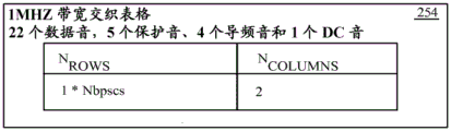
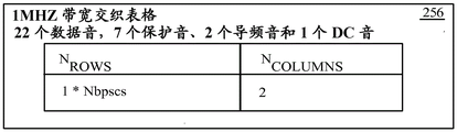
The RF receiver includes an OFDM module 1042 that receives electromagnetic energy at RF frequencies and extracts digital data therefrom. For 1MHZ operation, OFDM 1042 may extract an OFDM symbol comprising 20 data tones, seven guard tones, and one DC tone, such as OFDM symbol 1060 illustrated in fig. 1A. In other embodiments, the OFDM symbols may be encoded as OFDM symbols 1062, 1064, or 1066, as illustrated in fig. 1B-1D, respectively, where the interleaver configurations are described in tables 252, 254, or 256, respectively.
Fig. 1 may depict many different embodiments including a multiple-input multiple-output (MIMO) system with, for example, four spatial streams, and may depict a degenerate system in which one or more of the communication devices 1010, 1030, 1050, and 1055 includes a receiver and/or transmitter with a single antenna, including single-input single-output (SISO) systems, single-input multiple-output (SIMO) systems, and multiple-input single-output (MISO) systems. The wireless communication system 1000 of fig. 1 is intended to represent an Institute of Electrical and Electronics Engineers (IEEE) 802.11ah system. Similarly, devices 1010, 1030, 1050, and 1055 are intended to represent IEEE 802.11ah devices.
The OFDM modules 1022, 1032 transform the information signals into signals to be applied to the elements of the antenna array 1024. The antenna array 1024 is an array of individually excitable antenna elements. The signals applied to the elements of the antenna array 1024 cause the antenna array 1024 to radiate one to four spatial channels. Each spatial channel so formed may convey information to one or more of communications devices 1030, 1050, and 1055. Similarly, the communications device 1030 includes a transceiver 1040 for receiving signals from the communications device 1010 and transmitting signals to the communications device 1010. The transceiver 1040 may include an antenna array 1044 and may be capable of communicating with IEEE 802.11ah devices.
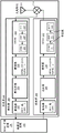
Fig. 2 illustrates an embodiment of an apparatus for transmitting Orthogonal Frequency Division Multiplexing (OFDM) -based communications in a wireless network. The apparatus includes a transceiver 200 coupled with Medium Access Control (MAC) sublayer logic 201 and physical layer logic 202. The MAC sublayer logic 201 may generate a frame and the physical layer logic 202 may encapsulate the frame (MPDU) with a preamble to generate a physical layer protocol data unit (PPDU) for transmission via the transceiver 200. For example, the frame constructor may generate a frame comprising: a type field specifying whether the frame is a management, control or data frame; and a subtype field for specifying a function of the frame. The control frame may include a ready-to-send frame or a clear-to-send frame. The management frame may include beacon, probe response, association response, and reassociation response frame types. And the data type frame is designed to transmit data.
The transceiver 200 includes a receiver 204 and a transmitter 206. The transmitter 206 may include one or more of an encoder 208, an interleaver 209, a modulator 210, and an OFDM module 212. The encoder 208 of the transmitter 206 receives data expected to be transmitted from the physical layer logic 202. The physical layer logic 202 may employ blocks or symbols (e.g., data bytes) to present data to the transceiver 200. The encoder 208 may encode the data using any of a number of algorithms now known or to be developed. The encoding can be performed to achieve one or more of a number of different purposes. For example, encoding may be performed to reduce the average number of bits per symbol that must be sent to transmit the information to be communicated. Encoding may be performed to reduce the probability of error in symbol detection at the receiver. Thus, the encoder may introduce redundancy to the data stream. Adding redundancy increases the channel bandwidth required to transmit information, but promotes fewer errors and enables signals to be transmitted at lower power. The encoding may also include encryption for security.
In the present embodiment, the encoder 208 may implement Binary Convolutional Coding (BCC) or low density parity check coding (LDPC), among other coding. The output of the encoder 210 is fed as a data stream to an interleaver 209. In some embodiments, a stream parser may reside between encoder 208 and interleaver 209 to parse the data into multiple data streams.
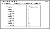
Fig. 2A illustrates a table 250 of interleaving for a 1MHz bandwidth. The table 250 describes the number of rows and columns that can be achieved when using 32 subcarriers, which includes 20 data subcarriers, seven guard subcarriers, four pilot subcarriers, and one DC subcarrier, for a 1MHz bandwidth channel via, for example, interleaver 209 interleaving. For example, the first row of table 250 shows 1 x Nbpscs row by 2 columns. Nbpscs may be equal to the number of coded bits per symbol (Ncbps) multiplied by the number of data subcarriers (Nsd), or (Nbpscs = Ncbps Nsd). Ncbps may be equal to Nsd times the modulation order (M), i.e. (Ncbps = Nsd × M), where M is equal to 1 for BPSK, 2 for QPSK, 4 for 16-QAM, 6 for 64 QAM, 8 for 256 QAM, and 10 for 1024 QAM. Thus, the number of rows (Nrows) for the 1MHz bandwidth and BPSK modulation and 20 data subcarriers in the first row of table 250 is Nrows =1 (20 × 1) × 20, where Npscs =400, Ncbps =20 and M = 1.
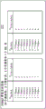
Additional entries in table 250 also include 5 x Nbpscs rows by 4 columns and 4 x Nbpscs rows by 5 columns, which are closer to a square than other entries in table 250. The actual number of rows may be determined as explained above in the calculation for the first row of table 250. Fig. 2B-2D depict alternative embodiments for interleaving tables 252, 254, and 256 based on corresponding OFDM symbols 1062, 1064, and 1066, respectively.
A modulator 210 of the transmitter 206 receives data from the interleaver 209. The purpose of the modulator 210 is to convert each block of binary data received from the encoder 208 into a unique continuous-time waveform that can be transmitted by the antenna as it is up-converted and amplified. The modulator 210 impresses the received data block on a sinusoid having a selected frequency. More specifically, modulator 210 maps the data blocks into a corresponding set of discrete amplitudes of the sinusoid or a set of discrete phases of the sinusoid or a set of discrete frequency shifts relative to the frequency of the sinusoid. The output of the modulator 210 may be a band pass signal.
In one embodiment, modulator 210 may implement Quadrature Amplitude Modulation (QAM), which adds two independent k-bit symbols from an information sequence onto two orthogonal carriers cos (2 π ft) and sin (2 π ft). QAM carries two digital bit streams by changing (modulating) the amplitude of two carriers using an Amplitude Shift Keying (ASK) digital modulation scheme. The two carriers are 90 out of phase with each other and are thus called orthogonal carriers or orthogonal components. The modulated waves are summed and the resulting waveform may be a combination of both Phase Shift Keying (PSK) and Amplitude Shift Keying (ASK). A limited number of at least two phases and at least two amplitudes may be used.
In some embodiments, modulator 210 maps the data block received from encoder 208 using four points on a constellation (evenly distributed around a circle), which is referred to as Quadrature Phase Shift Keying (QPSK). With these four phases, QPSK can encode two bits per symbol.
In another embodiment, modulator 210 maps blocks of data received from encoder 208 into a discrete set of phases of a carrier to produce a Phase Shift Keyed (PSK) signal. N-phase PSK signal is generated by inputting k = log of sequence2A block of N binary digits is generated mapped to one of N corresponding phases θ =2(N-1)/N (for N, a positive integer less than or equal to N). The resulting equivalent low-pass signal can be expressed as

Where g (t-nT) is the fundamental pulse, its shape can be optimized to improve the probability of accurate detection at the receiver by, for example, reducing inter-symbol interference. Such an embodiment may use Binary Phase Shift Keying (BPSK), the simplest form of Phase Shift Keying (PSK). BPSK uses two phases 180 ° apart and is most robust across all PSK because it takes the highest noise or distortion level to make an incorrect decision for the demodulator. In BPSK, there are two states for the signal phase: 0 and 180 degrees. The data is typically encoded differently before modulation.
In yet another embodiment, modulator 210 alternately maps the data blocks received from encoder 208 on two channels or streams called the I channel (for "in-phase") and the Q channel ("phase quadrature"), which is referred to as Staggered Quadrature Phase Shift Keying (SQPSK). SQPSK is a method of phase shift keying in which the signal carrier phase transitions are 90 degrees or 1/4 cycles at a time. The phase shift of 90 degrees is called phase quadrature. The single phase transition does not exceed 90 degrees. In SQPSK, there are four states: 0. +90, -90, and 180 degrees.
The output of the modulator 209 is fed to an Orthogonal Frequency Division Multiplexing (OFDM) module 212. The OFDM module 212 may include a space-time block coding (STBC) module 211, a Digital Beamforming (DBF) module 214, and an Inverse Fast Fourier Transform (IFFT) module 215. The STBC module 211 may receive constellation points corresponding to one or more spatial streams from the modulator 209 and may spread the spatial streams over a larger number of space-time streams (also referred to generally as data streams). In some embodiments, the STBC 211 may be controlled to traverse the spatial streams for a situation in which, for example, the number of spatial streams is the maximum number of space-time streams. Further embodiments may omit the STBC.
The OFDM module 212 impresses or maps the modulated data formed into OFDM symbols onto a plurality of orthogonal subcarriers so that the OFDM symbols are encoded with subcarriers or tones. In some embodiments, the OFDM symbols are fed to a Digital Beam Forming (DBF) module 214. Digital beam forming techniques may be employed to improve the efficiency and capacity of wireless systems. In general, digital beamforming uses digital signal processing algorithms that operate on signals received by and transmitted from an array of antenna elements. For example, multiple spatial channels may be formed and each spatial channel may be independently steered to maximize the signal power transmitted to and received from each of multiple user terminals. Furthermore, digital beamforming may be applied to minimize multipath fading and reject co-channel interference.
The output of the IFFT module 215 may be upconverted to a higher transport frequency or may be performed integrally with the upconversion. Shifting the signal to a much higher frequency prior to transmission enables the use of an antenna array of practical size. I.e. the higher the transmission frequency, the smaller the antenna may be. Thus, the up-converter multiplies the modulation waveform by the sinusoid to obtain a signal having a carrier frequency that is the sum of the center frequency of the waveform and the center frequency of the sinusoid. The operation is based on a trigonometric identity:

signals at the sum frequency (a + B) are passed and signals at the difference frequency (a-B) are filtered out. Thus, a band pass filter is provided to ideally filter out almost the signal to be transmitted (centered on the carrier (and) frequency).
The transceiver 200 may also include a duplexer 216 connected to an antenna array 218. Thus, in this embodiment, a single antenna array is used for both transmission and reception. In transmission, the signal passes through the duplexer 216 and drives the antenna with the upconverted information-bearing signal. During transmission, the duplexer 216 prevents signals to be transmitted from entering the receiver 204. Upon reception, the information-bearing signals received by the antenna array pass through duplexers 216 to deliver the signals from the antenna array to receiver 204. The duplexer 216 then prevents the received signal from entering the transmitter 206. Thus, the duplexers 216 operate as switches to alternately connect the antenna array elements to the receiver 204 and the transmitter 206.
Transceiver 200 may include a receiver 204 for receiving, demodulating, and decoding information-bearing communication signals. These communication signals may include, for example, 32 tones on a 1MHz carrier frequency. The 32 tones include 20 data tones, 7 guard tones, 4 pilot tones, and 1 DC tone, such as the OFDM packet 1060 illustrated in fig. 1A. For example, a data collection station for a farm that is compatible with IEEE 802.11ah may periodically receive data from low power sensors having an integrated wireless communication device that is compatible with IEEE 802.11 ah. The sensors may continue to enter a low power mode for a period of time, wake up periodically to collect data, and communicate with the data collection station periodically to transmit data collected by the sensors. In some embodiments, the sensors may actively initiate communication with the data collection station, transmit data indicative of the communication capabilities, and begin communicating data to the data collection station in response to a CTS or the like. In other embodiments, the sensor may transmit data to the data collection station in response to initiating communication by the data collection station.
Receiver 204 may include one or more of an OFDM module 222, a demodulator 224, a deinterleaver 225, and a decoder 226. OFDM 222 extracts signal information as OFDM symbols from a plurality of subcarriers onto which information-bearing communication signals are modulated. For example, an OFDM symbol may include data associated with 20 data subcarriers, four pilot subcarriers, seven guard subcarriers, and one DC subcarrier.
The OFDM module 222 may include a Fast Fourier Transform (FFT) module 219, a DBF module 220, and a STBC module 221. The received signal is fed from the antenna element 218, down-converted to a lower frequency and fed to an FFT module 219 to transform the communication signal from the time domain to the frequency domain. The DBF module 220 converts the N antenna signals into L information signals. And the STBC module 221 may transform the data stream from a space-time stream to a spatial stream. In one embodiment, demodulation is performed on the output data of the FFT in parallel. In another embodiment, independent demodulators 224 perform demodulation independently.
The demodulator 224 demodulates the spatial streams. Demodulation is the process of extracting data from spatial streams to produce demodulated spatial streams. The method of demodulation depends on the method by which information is modulated onto the received carrier signal and such information is included in the transmit vector (TXVECTOR), which is included in the communication signal. Thus, for example, if the modulation is BPSK, demodulation involves phase detection to convert the phase information into a binary sequence. Demodulation provides a sequence of information bits to the deinterleaver 225.
Those skilled in the art will recognize that the transceiver may include many additional functions not shown in fig. 2 and that the receiver 204 and transmitter 206 may be distinct devices rather than packaged into one transceiver. For example, embodiments of a transceiver may include a Dynamic Random Access Memory (DRAM), a reference oscillator, a filtering circuit, a spatial mapper, a cyclic shift insertion module, a guard interval insertion module, a synchronization circuit, possibly multiple frequency conversion stages and multiple amplification stages, and so on. Furthermore, some of the functions shown in fig. 2 may be integrated. For example, digital beamforming may be integrated with orthogonal frequency division multiplexing.
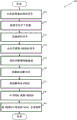
Fig. 3 depicts an embodiment of a flow diagram for transmitting communications with a transmitter as illustrated in fig. 2. The flow diagram 300 begins with receiving a frame from a frame builder (element 305). The MAC sublayer logic may generate a frame for transmission to another communication device and may pass the frame as an MPDU to a data unit builder in the physical layer that transforms the data into packets that may be transmitted to the other communication device. The data unit constructor may generate a preamble to encapsulate a PSDU (MPDU from the frame constructor) to form a PPDU for transmission (element 310). In some embodiments, more than one MPDU may be encapsulated in a PPDU.
Flow diagram 300 continues with a transmitter, such as transmitter 206, receiving a PPDU from the physical layer logic. The transmitter may encode (element 315) the PPDU with Binary Convolutional Coding (BCC) or low density parity check coding for controlling errors in the data transmission. More particularly, the transmitter may encode the PPDU via one or more encoding schemes (e.g., BBC or LDPC) described in a preamble of the PPDU.
The transmitter may interleave frames in one or more data streams (element 320). For example, an interleaver of a transmitter may receive a frame having data in multiple data streams from, for example, a stream parser. The interleaver may then store data from the data stream in rows of a memory and output data from columns of the memory as a data stream, thereby interleaving the data bits for transmission.
The transmitter may modulate the data stream via a modulation and coding scheme indicated by the preamble, e.g., BPSK, 16-QAM, 64-QAM, 256-QAM, QPSK, SQPSK, or the like (element 325). For example, a constellation mapper may map a sequence of bits in a data stream to constellation points (complex numbers).
The OFDM module of the transmitter may map the data stream of constellation points to a transmit chain as OFDM symbols encoded, for example, by 32 tones operating for a 1MHz bandwidth (element 330). For example, the OFDM module may include: an STBC coder for mapping the spatial stream of constellation points to a space-time stream; and a spatial mapper for mapping the space-time stream to a transmission chain which is an OFDM symbol encoded with 32 tones (e.g., 20 data tones, seven guard tones, four pilot tones, and one direct current tone). The spatial mapper may provide direct mapping, where constellation points from each space-time stream are mapped directly onto all transmit chains (one-to-one mapping). Spatial mapping may provide spatial spreading in which the vector of constellation points from all space-time streams is spread via matrix multiplication to produce an input of OFDM symbols encoded with 32 tones for all transmit chains. Alternatively, the spatial mapper may provide a DBF, where each vector from the constellation points for all space-time streams is multiplied by a steering vector matrix to produce an OFDM symbol encoded with 32 tones as input to the transmit chain.
The transmitter may transform the OFDM symbols encoded with, for example, 32 tones operating for a 1MHz bandwidth into the time domain via an inverse fourier transform (e.g., a 32-point inverse fourier transform) (element 335). The transmitter may then up-convert the OFDM symbols for transmission (element 340) and transmit the OFDM symbols as communication signals to an antenna to transmit the signals to another communication device (element 345). If there are more frames to transmit (element 360), the process may begin again at element 305.
Fig. 4 depicts an embodiment of a flow chart 400 for detecting and receiving a communication with a receiver as illustrated in fig. 2. The flow diagram 400 begins with a receiver, such as the receiver 204, detecting and receiving a communication signal from a transmitter via one or more antennas, such as antenna elements of the antenna array 218 (element 405). The receiver may downconvert (element 410) the communication signal to a lower frequency and transform (element 415) the communication signal to the frequency domain, e.g., via a 32-point FFT for a 1MHz bandwidth communication signal.
The transmitter may extract OFDM symbols encoded with 32 tones for a 1MHz bandwidth channel from the communication signal (element 420) and demodulate the OFDM symbols to produce a data stream of demodulated symbols (element 425). For example, a demodulator (e.g., demodulator 224) demodulates the signal information via, for example, BPSK, 16-QAM, 64-QAM, 256-QAM, QSPK, or SQPSK and outputs the signal as a bit stream to a deinterleaver (e.g., deinterleaver 225 in FIG. 2).
The deinterleaver may deinterleave the bits in the bitstream by storing the bits in, for example, 5 columns and removing the bits in 4 x Nbpscs rows. And a decoder, e.g., decoder 226, decodes the signal information from the deinterleaver to determine the PPDU via, e.g., BCC or LDPC (element 435). The transmitter may then extract the MPDU from the PPDU (element 440) and transmit the MPDU to MAC sublayer logic, e.g., MAC sublayer logic 202 (element 445).
Another embodiment is implemented as a program product for implementing the systems and methods described with reference to fig. 1-4. Some embodiments may take the form of an entirely hardware embodiment, an entirely software embodiment or an embodiment containing both hardware and software elements. One embodiment is implemented in software, which includes but is not limited to firmware, resident software, microcode, etc.
Furthermore, embodiments may take the form of a computer program product accessible from a computer-usable or computer-readable medium providing program code for use by or in connection with a computer or any instruction execution system. For the purposes of this description, a computer-usable or computer readable medium can be any apparatus that can contain, store, communicate, propagate, or transport the program for use by or in connection with the instruction execution system, apparatus, or device.
The medium can be an electronic, magnetic, optical, electromagnetic, infrared, or semiconductor system (or apparatus or device). Examples of a computer-readable medium include a semiconductor or solid state memory, magnetic tape, a removable computer diskette, a Random Access Memory (RAM), a read-only memory (ROM), a rigid magnetic disk and an optical disk. Current examples of optical disks include compact disk-read only memory (CD-ROM), compact disk-read/write (CD-R/W), and DVD.
A data processing system suitable for storing and/or executing program code will include at least one processor coupled directly or indirectly to memory elements through a system bus. These memory elements can include local memory employed during actual execution of the program code, bulk storage, and cache memories which provide temporary storage of at least some program code in order to reduce the number of times code must be retrieved from bulk storage during execution.
The logic as described above may be part of the design for an integrated circuit chip. The chip design is created in a graphical computer programming language and stored in a computer storage medium (e.g., a disk, tape, physical hard drive, or virtual hard drive, such as in a storage access network). If the designer does not fabricate chips or the photolithographic masks used to fabricate chips, the designer transmits the resulting design by physical means (e.g., by providing a copy of the storage medium storing the design) or electronically (e.g., through the Internet) to such entities, directly or indirectly. The stored design is then converted into the appropriate format (e.g., GDSII) for fabrication.
The resulting integrated circuit chips may be distributed by the manufacturer in raw wafer form (i.e., as a single wafer with multiple unpackaged chips), as a bare die, or in a packaged form. In the latter case, the chip is mounted on a single chip package (e.g., a plastic carrier with leads attached to a motherboard or other higher level carrier) or in a multi-chip package (e.g., a ceramic carrier with either or both surface interconnections or buried interconnections). In any case, the chip is then integrated with other chips, discrete circuit elements, and/or other signal processing devices as part of either (a) an intermediate product (e.g., a motherboard) or (b) an end product.
Claims (38)
1. An apparatus for Orthogonal Frequency Division Multiplexing (OFDM) wireless communication, the apparatus comprising:
an encoder configured to encode data to generate encoded bits;
an interleaver configured to interleave the coded bits for a megahertz (1 MHz) bandwidth to produce a plurality of data streams;
a modulator configured to modulate the plurality of data streams; and
an OFDM module configured to convert the modulated data stream into a plurality of OFDM symbols, the OFDM symbols being encoded with a plurality of subcarriers including twenty-four data subcarriers, two pilot subcarriers, five guard subcarriers, and one Direct Current (DC) subcarrier.
2. The device of claim 1, wherein the coded bits are arranged by the interleaver to have eight columns and 3 x NBPSCSIn a table of rows, where NBPSCSRepresenting the number of coded bits per subcarrier.
3. The apparatus of claim 1, wherein:
the modulator is configured to modulate the plurality of data streams with a modulation format selected from the group consisting of: binary quadrature phase shift keying (BPSK); a 64-point constellation Quadrature Amplitude Modulation (QAM); 256-point constellation QAM; and Quadrature Phase Shift Keying (QPSK).
4. The apparatus of claim 3, wherein the modulator is configured to modulate the plurality of data streams with a coding rate selected from the group consisting of a coding rate of 1/2, a coding rate of 3/4, a coding rate of 2/3, and a coding rate of 5/6.
5. The apparatus of claim 1, wherein the OFDM module comprises:
an inverse Fourier transformer configured to perform an Inverse Discrete Fourier Transform (IDFT) on the plurality of subcarriers.
6. The apparatus of claim 1, wherein the OFDM module comprises:
a digital beamforming module configured to transform the plurality of information signals into a plurality of antenna signals.
7. The apparatus of claim 1, wherein the OFDM module comprises:
a space-time block coding (STBC) module configured to spread a plurality of spatial streams to a plurality of space-time streams.
8. The apparatus of claim 1, configured to transmit the OFDM wireless communication over a 1Mhz channel.
9. The apparatus of any of claims 1-8, comprising an antenna and a transmitter.
10. An apparatus for Orthogonal Frequency Division Multiplexing (OFDM) wireless communication, the apparatus comprising:
an OFDM module configured to receive a plurality of OFDM symbols and transform the plurality of OFDM symbols into a plurality of spatial streams, an OFDM symbol being encoded with a plurality of subcarriers comprising twenty-four data subcarriers, two pilot subcarriers, five guard subcarriers, and one Direct Current (DC) subcarrier;
a demodulator configured to demodulate the plurality of spatial streams to produce a sequence of bits;
a deinterleaver configured to deinterleave the sequence of bits for a one megahertz (1 MHz) bandwidth to produce coded bits; and
a decoder configured to decode the encoded bits to obtain data.
11. The apparatus of claim 10, wherein:
the deinterleaver is configured to arrange the sequence of bits to have eight columns and 3 × NBPSCSIn a table of rows, where NBPSCSRepresenting the number of coded bits per subcarrier.
12. The apparatus of claim 10, wherein:
the demodulator is configured to demodulate the plurality of spatial streams with a modulation format selected from the group consisting of: binary quadrature phase shift keying (BPSK); a 64-point constellation Quadrature Amplitude Modulation (QAM); 256-point constellation QAM; and Quadrature Phase Shift Keying (QPSK).
13. The apparatus of claim 12, wherein the demodulator is configured to demodulate the plurality of spatial streams based on a coding rate selected from the group consisting of a coding rate of 1/2, a coding rate of 3/4, a coding rate of 2/3, and a coding rate of 5/6.
14. The apparatus of claim 10, wherein the OFDM module comprises:
a Fourier transformer configured to transform the communication signal from a time domain to a frequency domain.
15. The apparatus of claim 10, configured to receive the OFDM wireless communication over a 1MHz channel.
16. The device of any of claims 10-15, comprising an antenna.
17. A method of communicating communication signals configured to a Wireless Local Area Network (WLAN), the method comprising:
encoding the data to produce encoded bits;
interleaving the coded bits for a one megahertz (1 MHz) bandwidth to produce a plurality of data streams;
modulating the plurality of data streams;
generating an Orthogonal Frequency Division Multiplexing (OFDM) communication signal comprising a plurality of subcarriers, wherein the plurality of subcarriers includes twenty-four data subcarriers, two pilot subcarriers, five guard subcarriers, and one Direct Current (DC) subcarrier; and
communicating the OFDM communication signal over a 1MHz channel.
18. The method of claim 17, wherein the coded bits are arranged by the interleaving to have eight columns and 3 x NBPSCSIn a table of rows, where NBPSCSRepresenting the number of coded bits per subcarrier.
19. The method of claim 17, comprising:
modulating the plurality of data streams with a modulation format selected from the group consisting of: binary quadrature phase shift keying (BPSK); a 64-point constellation Quadrature Amplitude Modulation (QAM); 256-point constellation QAM; and Quadrature Phase Shift Keying (QPSK).
20. The method of claim 17, comprising:
the plurality of data streams are modulated with a coding rate selected from the group consisting of a coding rate of 1/2, a coding rate of 3/4, a coding rate of 2/3, and a coding rate of 5/6.
21. The method of claim 17, comprising:
performing an inverse discrete Fourier transform on the plurality of subcarriers to generate the OFDM communication signal.
22. A method of communicating communication signals configured to a Wireless Local Area (WLAN) network, the method comprising:
receiving a plurality of OFDM symbols and transforming the plurality of OFDM symbols into a plurality of spatial streams, an OFDM symbol being encoded with a plurality of subcarriers comprising twenty-four data subcarriers, two pilot subcarriers, five guard subcarriers, and one Direct Current (DC) subcarrier;
demodulating the plurality of spatial streams to produce a sequence of bits;
deinterleaving the sequence of bits for a one megahertz (1 MHz) bandwidth to produce encoded bits; and
the coded bits are decoded to obtain data.
23. The method of claim 22, wherein the deinterleaving comprises:
arranging the sequence of bits to have eight columns and 3 x NBPSCSIn a table of rows, where NBPSCSRepresenting the number of coded bits per subcarrier.
24. The method of claim 22, wherein the demodulating comprises:
demodulating the plurality of spatial streams with a modulation format selected from the group consisting of binary quadrature phase shift keying (BPSK), 64-point constellation Quadrature Amplitude Modulation (QAM), 256-point constellation QAM, and Quadrature Phase Shift Keying (QPSK).
25. The method of claim 22, wherein the demodulating comprises: demodulating the plurality of spatial streams based on a coding rate selected from the group consisting of a coding rate of 1/2, a coding rate of 3/4, a coding rate of 2/3, and a coding rate of 5/6.
26. The method of claim 22, comprising:
the communication signal is transformed from the time domain to the frequency domain.
27. A storage medium having stored thereon instructions which, when executed by a machine, result in a method according to any of claims 17-26.
28. An apparatus for wireless communication, comprising means for causing a wireless communication device to perform the method of any of claims 17-26.
29. An apparatus for wireless communication, comprising:
means for encoding data to produce encoded bits;
means for interleaving the coded bits for a one megahertz (1 MHz) bandwidth to produce a plurality of data streams;
means for modulating the plurality of data streams;
means for generating an Orthogonal Frequency Division Multiplexed (OFDM) communication signal comprising a plurality of subcarriers, wherein the plurality of subcarriers includes twenty-four data subcarriers, two pilot subcarriers, five guard subcarriers, and one Direct Current (DC) subcarrier; and
means for communicating the OFDM communication signal over a 1MHz channel.
30. The apparatus of claim 29, wherein the arrangement of the means for interleaving the bits is arranged to have eight columns and 3 x NBPSCSIn a table of rows, where NBPSCSRepresenting the number of coded bits per subcarrier.
31. The apparatus of claim 29, comprising:
means for modulating the plurality of data streams with a modulation format selected from the group consisting of: binary quadrature phase shift keying (BPSK); a 64-point constellation Quadrature Amplitude Modulation (QAM); 256-point constellation QAM; and Quadrature Phase Shift Keying (QPSK).
32. The apparatus of claim 29, comprising:
means for modulating the plurality of data streams with a coding rate selected from the group consisting of a coding rate of 1/2, a coding rate of 3/4, a coding rate of 2/3, and a coding rate of 5/6.
33. The apparatus of claim 29, comprising:
means for performing an inverse discrete Fourier transform on the plurality of subcarriers to generate the OFDM communication signal.
34. An apparatus for wireless communication, comprising:
means for receiving a plurality of OFDM symbols and transforming the plurality of OFDM symbols into a plurality of spatial streams, an OFDM symbol being encoded with a plurality of subcarriers comprising twenty-four data subcarriers, two pilot subcarriers, five guard subcarriers, and one Direct Current (DC) subcarrier;
means for demodulating the plurality of spatial streams to produce a sequence of bits;
means for deinterleaving the sequence of bits for a one megahertz (1 MHz) bandwidth to produce encoded bits; and
means for decoding the encoded bits to obtain data.
35. The apparatus of claim 34, wherein the means for deinterleaving comprises:
for arranging the sequence of bits in a sequence having eight columns and 3 x NBPSCSElements in a table of rows, where NBPSCSRepresenting the number of coded bits per subcarrier.
36. The apparatus of claim 34, wherein the means for demodulating comprises:
means for demodulating the plurality of spatial streams with a modulation format selected from the group consisting of binary quadrature phase shift keying (BPSK), 64-point constellation Quadrature Amplitude Modulation (QAM), 256-point constellation QAM, and Quadrature Phase Shift Keying (QPSK).
37. The apparatus of claim 34, wherein the means for demodulating comprises: means for demodulating the plurality of spatial streams based on a coding rate selected from the group consisting of a coding rate of 1/2, a coding rate of 3/4, a coding rate of 2/3, and a coding rate of 5/6.
38. The apparatus of claim 34, comprising:
means for transforming the communication signal from the time domain to the frequency domain.
Applications Claiming Priority (3)
| Application Number | Priority Date | Filing Date | Title |
|---|---|---|---|
| US201161544775P | 2011-10-07 | 2011-10-07 | |
| US61/544775 | 2011-10-07 | ||
| CN201180074605.XA CN103907324B (en) | 2011-10-07 | 2011-12-31 | Method and apparatus for the communication in low power radio network |
Related Parent Applications (1)
| Application Number | Title | Priority Date | Filing Date |
|---|---|---|---|
| CN201180074605.XA Division CN103907324B (en) | 2011-10-07 | 2011-12-31 | Method and apparatus for the communication in low power radio network |
Publications (2)
| Publication Number | Publication Date |
|---|---|
| CN108449299A CN108449299A (en) | 2018-08-24 |
| CN108449299B true CN108449299B (en) | 2022-01-14 |
Family
ID=48044045
Family Applications (2)
| Application Number | Title | Priority Date | Filing Date |
|---|---|---|---|
| CN201810204542.9A Active CN108449299B (en) | 2011-10-07 | 2011-12-31 | Method and arrangement for communication in a low power wireless network |
| CN201180074605.XA Active CN103907324B (en) | 2011-10-07 | 2011-12-31 | Method and apparatus for the communication in low power radio network |
Family Applications After (1)
| Application Number | Title | Priority Date | Filing Date |
|---|---|---|---|
| CN201180074605.XA Active CN103907324B (en) | 2011-10-07 | 2011-12-31 | Method and apparatus for the communication in low power radio network |
Country Status (7)
| Country | Link |
|---|---|
| US (2) | US9344179B2 (en) |
| EP (1) | EP2764669B1 (en) |
| CN (2) | CN108449299B (en) |
| AU (1) | AU2011378436B2 (en) |
| IN (1) | IN2014CN02311A (en) |
| RU (1) | RU2638777C2 (en) |
| WO (1) | WO2013052079A1 (en) |
Families Citing this family (27)
| Publication number | Priority date | Publication date | Assignee | Title |
|---|---|---|---|---|
| EP2764669B1 (en) | 2011-10-07 | 2016-05-18 | Intel Corporation | Methods and arrangements for communications in low power wireless networks |
| JP5763044B2 (en) * | 2012-12-19 | 2015-08-12 | 株式会社東芝 | Wireless communication apparatus, connection control method, and connection control program |
| EP3496507B1 (en) * | 2014-07-31 | 2022-02-23 | Huawei Technologies Co., Ltd. | Transmission device and method for transmitting data frame |
| KR102106323B1 (en) * | 2014-09-24 | 2020-05-04 | 한국전자통신연구원 | OFDM signal transmitting apparatus and method for OFDM-PON |
| US10164729B2 (en) * | 2014-10-02 | 2018-12-25 | Marvell World Trade Ltd. | System and method of tone mapping during single user and multiple user operating modes including transmissions respectively of OFDM symbols and OFDMA symbols in a WLAN |
| WO2016060504A1 (en) * | 2014-10-16 | 2016-04-21 | 엘지전자 주식회사 | Method and device for allocating wireless resources in bandwidths of different sizes in wireless lan |
| US9838169B2 (en) * | 2014-10-29 | 2017-12-05 | Samsung Electronics Co., Ltd. | Methods and apparatus using interleaved guard OFDM in wireless communication systems |
| US9407354B2 (en) * | 2014-12-31 | 2016-08-02 | Hughes Network Systems, L.L.C. | Outdoor digital modulator system for use with a linear radio, and a method thereof |
| ES2929221T3 (en) | 2015-01-26 | 2022-11-28 | Huawei Tech Co Ltd | System and method for communicating an orthogonal frequency division multiplexed (OFDM) frame format |
| WO2016148411A1 (en) * | 2015-03-16 | 2016-09-22 | 엘지전자(주) | Method for multiple user transmission and reception in wireless communication system, and apparatus therefor |
| US10182442B2 (en) | 2015-04-26 | 2019-01-15 | Lg Electronics Inc. | Method and device for performing communication by using plurality of resource arrangement techniques in wireless LAN system |
| US9602232B2 (en) | 2015-05-19 | 2017-03-21 | Samsung Electronics Co., Ltd. | Transmitting apparatus and mapping method thereof |
| US20170013604A1 (en) * | 2015-07-07 | 2017-01-12 | Qualcomm Incorporated | Techniques for transmitting/receiving wireless local area network information |
| CN106972913A (en) * | 2016-01-13 | 2017-07-21 | 晨星半导体股份有限公司 | Handle the device and method of position configuration |
| CN105762945B (en) * | 2016-05-12 | 2018-09-21 | 重庆大学 | For the compound source formula electric energy and signal parallel transmission method in ECPT systems |
| CN109565491B (en) * | 2016-09-09 | 2022-04-08 | 英特尔公司 | Signal spectrum for wireless networks |
| US11817987B2 (en) * | 2017-04-11 | 2023-11-14 | Cohere Technologies, Inc. | Digital communication using dispersed orthogonal time frequency space modulated signals |
| WO2018204543A1 (en) * | 2017-05-03 | 2018-11-08 | Assia Spe, Llc | Systems and methods for implementing high-speed waveguide transmission over wires |
| CN108965184B (en) * | 2017-05-25 | 2021-08-17 | 中兴通讯股份有限公司 | Discrete multi-audio modulation multiplexing system and method |
| CN109981155B (en) * | 2017-12-27 | 2021-08-13 | 华为技术有限公司 | Beam training method and related equipment |
| US10862637B2 (en) * | 2018-11-08 | 2020-12-08 | Huawei Technologies Co., Ltd. | Segment based reference signal |
| CN112468260B (en) * | 2019-09-09 | 2022-11-18 | 北京东土科技股份有限公司 | Physical frame generation method, apparatus, electronic device and medium |
| WO2021086109A1 (en) * | 2019-10-31 | 2021-05-06 | 엘지전자 주식회사 | Technique for transmitting ltf signal in wireless communication system |
| CN110850773B (en) * | 2019-11-14 | 2021-01-22 | 北京和利时系统工程有限公司 | Signal acquisition method and device, computer storage medium and electronic equipment |
| CN112073353B (en) * | 2020-09-09 | 2023-07-04 | 浙江树人学院(浙江树人大学) | LTE-U communication system based on FPGA |
| CN113922927A (en) * | 2021-07-29 | 2022-01-11 | 之讯科技(深圳)有限公司 | Wireless communication system and method based on coded aperture |
| US20240063876A1 (en) * | 2022-08-16 | 2024-02-22 | Qualcomm Incorporated | Antenna switching in frequency bands with power spectral density (psd) limits |
Family Cites Families (27)
| Publication number | Priority date | Publication date | Assignee | Title |
|---|---|---|---|---|
| US6947748B2 (en) * | 2000-12-15 | 2005-09-20 | Adaptix, Inc. | OFDMA with adaptive subcarrier-cluster configuration and selective loading |
| RU2408986C2 (en) | 2003-08-20 | 2011-01-10 | Панасоник Корпорэйшн | Wireless communication device and method of subcarrier dedication |
| WO2005071909A1 (en) * | 2004-01-26 | 2005-08-04 | Samsung Electronics Co., Ltd. | Method and apparatus for setting, transmitting and receiving data for virtual carrier sensing in wireless network communication |
| US20050180312A1 (en) * | 2004-02-18 | 2005-08-18 | Walton J. R. | Transmit diversity and spatial spreading for an OFDM-based multi-antenna communication system |
| US7873022B2 (en) * | 2004-02-19 | 2011-01-18 | Broadcom Corporation | Multiple input multiple output wireless local area network communications |
| JP4652846B2 (en) | 2004-03-11 | 2011-03-16 | パナソニック株式会社 | Communication terminal device and communication relay method |
| US7630356B2 (en) * | 2004-04-05 | 2009-12-08 | Nortel Networks Limited | Methods for supporting MIMO transmission in OFDM applications |
| WO2006000091A1 (en) | 2004-06-24 | 2006-01-05 | Nortel Networks Limited | Preambles in ofdma system |
| US7535972B2 (en) | 2005-06-24 | 2009-05-19 | Broadcom Corporation | Programmable transmitter |
| US8175190B2 (en) * | 2005-07-27 | 2012-05-08 | Qualcomm Atheros, Inc. | Managing spectra of modulated signals in a communication network |
| JP4373977B2 (en) * | 2005-12-22 | 2009-11-25 | 株式会社東芝 | Wireless communication system and wireless device |
| WO2007100774A1 (en) | 2006-02-28 | 2007-09-07 | Atc Technologies, Llc | Systems, methods and transceivers for wireless communications over discontiguous spectrum segments |
| US7869801B2 (en) * | 2006-10-18 | 2011-01-11 | Pine Valley Investments, Inc. | Method for terminal configuration over a radio control channel |
| US8085873B2 (en) * | 2007-01-02 | 2011-12-27 | Qualcomm, Incorporated | Systems and methods for enhanced channel estimation in wireless communication systems |
| RU2437237C1 (en) | 2007-09-28 | 2011-12-20 | ЭлДжи ЭЛЕКТРОНИКС ИНК. | Device for signal transfer and reception and method of signal transfer and reception |
| US8369301B2 (en) * | 2007-10-17 | 2013-02-05 | Zte (Usa) Inc. | OFDM/OFDMA frame structure for communication systems |
| CN101656592B (en) * | 2008-08-20 | 2013-02-13 | 上海贝尔股份有限公司 | Method and device for adaptive modulation and coding |
| US8130714B2 (en) * | 2008-10-20 | 2012-03-06 | Lg Electronics | Method and apparatus for transmitting signal in a wireless communication system |
| CN102292986B (en) * | 2009-02-12 | 2013-12-11 | Lg电子株式会社 | Apparatus for transmitting and receiving a signal and method of transmitting and receiving a signal |
| US9294316B2 (en) | 2010-06-24 | 2016-03-22 | Texas Instruments Incorporated | Scrambling sequences for wireless networks |
| CN101977171B (en) * | 2010-10-15 | 2013-01-16 | 清华大学 | Multiple access signal transmission method for broadband wireless communication system |
| CN102035785B (en) * | 2010-11-12 | 2013-04-03 | 清华大学 | Frequency-division duplexing transmission method for wideband wireless communication system |
| CN102035786B (en) * | 2010-11-12 | 2013-05-01 | 清华大学 | Time division duplex transmission method for broadband wireless communication system |
| US8625690B2 (en) * | 2011-03-04 | 2014-01-07 | Qualcomm Incorporated | Systems and methods for wireless communication in sub gigahertz bands |
| US20130215993A1 (en) * | 2011-08-24 | 2013-08-22 | Qualcomm Incorporated | Systems and methods for detecting transmissions based on 32-point and 64-point fast fourier transforms |
| US9049155B2 (en) * | 2011-09-06 | 2015-06-02 | Qualcomm Incorporated | Dual interpretation of a length field of a signal unit |
| EP2764669B1 (en) | 2011-10-07 | 2016-05-18 | Intel Corporation | Methods and arrangements for communications in low power wireless networks |
-
2011
- 2011-12-31 EP EP11873740.2A patent/EP2764669B1/en active Active
- 2011-12-31 WO PCT/US2011/068262 patent/WO2013052079A1/en active Application Filing
- 2011-12-31 CN CN201810204542.9A patent/CN108449299B/en active Active
- 2011-12-31 IN IN2311CHN2014 patent/IN2014CN02311A/en unknown
- 2011-12-31 AU AU2011378436A patent/AU2011378436B2/en active Active
- 2011-12-31 CN CN201180074605.XA patent/CN103907324B/en active Active
- 2011-12-31 US US13/977,707 patent/US9344179B2/en active Active
-
2014
- 2014-12-03 US US14/558,778 patent/US9214998B2/en active Active
-
2015
- 2015-12-17 RU RU2015154402A patent/RU2638777C2/en active
Also Published As
| Publication number | Publication date |
|---|---|
| AU2011378436A1 (en) | 2014-04-24 |
| EP2764669A1 (en) | 2014-08-13 |
| EP2764669B1 (en) | 2016-05-18 |
| IN2014CN02311A (en) | 2015-06-19 |
| US20150010098A1 (en) | 2015-01-08 |
| CN103907324A (en) | 2014-07-02 |
| CN103907324B (en) | 2018-03-27 |
| US20150085946A1 (en) | 2015-03-26 |
| CN108449299A (en) | 2018-08-24 |
| US9214998B2 (en) | 2015-12-15 |
| US9344179B2 (en) | 2016-05-17 |
| RU2015154402A (en) | 2017-06-22 |
| RU2638777C2 (en) | 2017-12-15 |
| EP2764669A4 (en) | 2015-05-27 |
| AU2011378436B2 (en) | 2015-12-17 |
| WO2013052079A1 (en) | 2013-04-11 |
| RU2014117526A (en) | 2015-11-10 |
Similar Documents
| Publication | Publication Date | Title |
|---|---|---|
| CN108449299B (en) | Method and arrangement for communication in a low power wireless network | |
| US20230319704A1 (en) | Methods and arrangements for low power wireless networks | |
| US9867082B2 (en) | Methods and arrangements for communications in low power wireless networks | |
| US9559810B2 (en) | Methods and arrangements for a check sequence | |
| US20140071956A1 (en) | Methods and arrangements to signal short interframe spaces | |
| RU2574335C2 (en) | Methods and arrangements for communications in low-power wireless communication networks |
Legal Events
| Date | Code | Title | Description |
|---|---|---|---|
| PB01 | Publication | ||
| PB01 | Publication | ||
| SE01 | Entry into force of request for substantive examination | ||
| SE01 | Entry into force of request for substantive examination | ||
| GR01 | Patent grant | ||
| GR01 | Patent grant |