CN108430405B - Porous structures for sustained release drug delivery devices - Google Patents
Porous structures for sustained release drug delivery devices Download PDFInfo
- Publication number
- CN108430405B CN108430405B CN201680077812.3A CN201680077812A CN108430405B CN 108430405 B CN108430405 B CN 108430405B CN 201680077812 A CN201680077812 A CN 201680077812A CN 108430405 B CN108430405 B CN 108430405B
- Authority
- CN
- China
- Prior art keywords
- porous structure
- barrier layer
- reservoir
- therapeutic
- therapeutic agent
- Prior art date
- Legal status (The legal status is an assumption and is not a legal conclusion. Google has not performed a legal analysis and makes no representation as to the accuracy of the status listed.)
- Active
Links
Images


Classifications
-
- A—HUMAN NECESSITIES
- A61—MEDICAL OR VETERINARY SCIENCE; HYGIENE
- A61M—DEVICES FOR INTRODUCING MEDIA INTO, OR ONTO, THE BODY; DEVICES FOR TRANSDUCING BODY MEDIA OR FOR TAKING MEDIA FROM THE BODY; DEVICES FOR PRODUCING OR ENDING SLEEP OR STUPOR
- A61M37/00—Other apparatus for introducing media into the body; Percutany, i.e. introducing medicines into the body by diffusion through the skin
-
- A—HUMAN NECESSITIES
- A61—MEDICAL OR VETERINARY SCIENCE; HYGIENE
- A61F—FILTERS IMPLANTABLE INTO BLOOD VESSELS; PROSTHESES; DEVICES PROVIDING PATENCY TO, OR PREVENTING COLLAPSING OF, TUBULAR STRUCTURES OF THE BODY, e.g. STENTS; ORTHOPAEDIC, NURSING OR CONTRACEPTIVE DEVICES; FOMENTATION; TREATMENT OR PROTECTION OF EYES OR EARS; BANDAGES, DRESSINGS OR ABSORBENT PADS; FIRST-AID KITS
- A61F9/00—Methods or devices for treatment of the eyes; Devices for putting-in contact lenses; Devices to correct squinting; Apparatus to guide the blind; Protective devices for the eyes, carried on the body or in the hand
- A61F9/0008—Introducing ophthalmic products into the ocular cavity or retaining products therein
- A61F9/0017—Introducing ophthalmic products into the ocular cavity or retaining products therein implantable in, or in contact with, the eye, e.g. ocular inserts
-
- A—HUMAN NECESSITIES
- A61—MEDICAL OR VETERINARY SCIENCE; HYGIENE
- A61F—FILTERS IMPLANTABLE INTO BLOOD VESSELS; PROSTHESES; DEVICES PROVIDING PATENCY TO, OR PREVENTING COLLAPSING OF, TUBULAR STRUCTURES OF THE BODY, e.g. STENTS; ORTHOPAEDIC, NURSING OR CONTRACEPTIVE DEVICES; FOMENTATION; TREATMENT OR PROTECTION OF EYES OR EARS; BANDAGES, DRESSINGS OR ABSORBENT PADS; FIRST-AID KITS
- A61F9/00—Methods or devices for treatment of the eyes; Devices for putting-in contact lenses; Devices to correct squinting; Apparatus to guide the blind; Protective devices for the eyes, carried on the body or in the hand
- A61F9/0008—Introducing ophthalmic products into the ocular cavity or retaining products therein
- A61F9/0026—Ophthalmic product dispenser attachments to facilitate positioning near the eye
-
- A—HUMAN NECESSITIES
- A61—MEDICAL OR VETERINARY SCIENCE; HYGIENE
- A61J—CONTAINERS SPECIALLY ADAPTED FOR MEDICAL OR PHARMACEUTICAL PURPOSES; DEVICES OR METHODS SPECIALLY ADAPTED FOR BRINGING PHARMACEUTICAL PRODUCTS INTO PARTICULAR PHYSICAL OR ADMINISTERING FORMS; DEVICES FOR ADMINISTERING FOOD OR MEDICINES ORALLY; BABY COMFORTERS; DEVICES FOR RECEIVING SPITTLE
- A61J1/00—Containers specially adapted for medical or pharmaceutical purposes
- A61J1/05—Containers specially adapted for medical or pharmaceutical purposes for collecting, storing or administering blood, plasma or medical fluids ; Infusion or perfusion containers
-
- A—HUMAN NECESSITIES
- A61—MEDICAL OR VETERINARY SCIENCE; HYGIENE
- A61M—DEVICES FOR INTRODUCING MEDIA INTO, OR ONTO, THE BODY; DEVICES FOR TRANSDUCING BODY MEDIA OR FOR TAKING MEDIA FROM THE BODY; DEVICES FOR PRODUCING OR ENDING SLEEP OR STUPOR
- A61M31/00—Devices for introducing or retaining media, e.g. remedies, in cavities of the body
- A61M31/002—Devices for releasing a drug at a continuous and controlled rate for a prolonged period of time
-
- A—HUMAN NECESSITIES
- A61—MEDICAL OR VETERINARY SCIENCE; HYGIENE
- A61P—SPECIFIC THERAPEUTIC ACTIVITY OF CHEMICAL COMPOUNDS OR MEDICINAL PREPARATIONS
- A61P27/00—Drugs for disorders of the senses
- A61P27/02—Ophthalmic agents
-
- A—HUMAN NECESSITIES
- A61—MEDICAL OR VETERINARY SCIENCE; HYGIENE
- A61F—FILTERS IMPLANTABLE INTO BLOOD VESSELS; PROSTHESES; DEVICES PROVIDING PATENCY TO, OR PREVENTING COLLAPSING OF, TUBULAR STRUCTURES OF THE BODY, e.g. STENTS; ORTHOPAEDIC, NURSING OR CONTRACEPTIVE DEVICES; FOMENTATION; TREATMENT OR PROTECTION OF EYES OR EARS; BANDAGES, DRESSINGS OR ABSORBENT PADS; FIRST-AID KITS
- A61F2250/00—Special features of prostheses classified in groups A61F2/00 - A61F2/26 or A61F2/82 or A61F9/00 or A61F11/00 or subgroups thereof
- A61F2250/0058—Additional features; Implant or prostheses properties not otherwise provided for
- A61F2250/0067—Means for introducing or releasing pharmaceutical products into the body
- A61F2250/0068—Means for introducing or releasing pharmaceutical products into the body the pharmaceutical product being in a reservoir
-
- A—HUMAN NECESSITIES
- A61—MEDICAL OR VETERINARY SCIENCE; HYGIENE
- A61M—DEVICES FOR INTRODUCING MEDIA INTO, OR ONTO, THE BODY; DEVICES FOR TRANSDUCING BODY MEDIA OR FOR TAKING MEDIA FROM THE BODY; DEVICES FOR PRODUCING OR ENDING SLEEP OR STUPOR
- A61M2205/00—General characteristics of the apparatus
- A61M2205/02—General characteristics of the apparatus characterised by a particular materials
-
- A—HUMAN NECESSITIES
- A61—MEDICAL OR VETERINARY SCIENCE; HYGIENE
- A61M—DEVICES FOR INTRODUCING MEDIA INTO, OR ONTO, THE BODY; DEVICES FOR TRANSDUCING BODY MEDIA OR FOR TAKING MEDIA FROM THE BODY; DEVICES FOR PRODUCING OR ENDING SLEEP OR STUPOR
- A61M2205/00—General characteristics of the apparatus
- A61M2205/04—General characteristics of the apparatus implanted
-
- A—HUMAN NECESSITIES
- A61—MEDICAL OR VETERINARY SCIENCE; HYGIENE
- A61M—DEVICES FOR INTRODUCING MEDIA INTO, OR ONTO, THE BODY; DEVICES FOR TRANSDUCING BODY MEDIA OR FOR TAKING MEDIA FROM THE BODY; DEVICES FOR PRODUCING OR ENDING SLEEP OR STUPOR
- A61M2205/00—General characteristics of the apparatus
- A61M2205/12—General characteristics of the apparatus with interchangeable cassettes forming partially or totally the fluid circuit
- A61M2205/125—General characteristics of the apparatus with interchangeable cassettes forming partially or totally the fluid circuit with incorporated filters
-
- A—HUMAN NECESSITIES
- A61—MEDICAL OR VETERINARY SCIENCE; HYGIENE
- A61M—DEVICES FOR INTRODUCING MEDIA INTO, OR ONTO, THE BODY; DEVICES FOR TRANSDUCING BODY MEDIA OR FOR TAKING MEDIA FROM THE BODY; DEVICES FOR PRODUCING OR ENDING SLEEP OR STUPOR
- A61M2205/00—General characteristics of the apparatus
- A61M2205/75—General characteristics of the apparatus with filters
-
- A—HUMAN NECESSITIES
- A61—MEDICAL OR VETERINARY SCIENCE; HYGIENE
- A61M—DEVICES FOR INTRODUCING MEDIA INTO, OR ONTO, THE BODY; DEVICES FOR TRANSDUCING BODY MEDIA OR FOR TAKING MEDIA FROM THE BODY; DEVICES FOR PRODUCING OR ENDING SLEEP OR STUPOR
- A61M5/00—Devices for bringing media into the body in a subcutaneous, intra-vascular or intramuscular way; Accessories therefor, e.g. filling or cleaning devices, arm-rests
- A61M5/14—Infusion devices, e.g. infusing by gravity; Blood infusion; Accessories therefor
- A61M5/142—Pressure infusion, e.g. using pumps
- A61M5/14244—Pressure infusion, e.g. using pumps adapted to be carried by the patient, e.g. portable on the body
- A61M5/14276—Pressure infusion, e.g. using pumps adapted to be carried by the patient, e.g. portable on the body specially adapted for implantation
Landscapes
- Health & Medical Sciences (AREA)
- Engineering & Computer Science (AREA)
- Public Health (AREA)
- Veterinary Medicine (AREA)
- Life Sciences & Earth Sciences (AREA)
- Animal Behavior & Ethology (AREA)
- General Health & Medical Sciences (AREA)
- Biomedical Technology (AREA)
- Heart & Thoracic Surgery (AREA)
- Hematology (AREA)
- Vascular Medicine (AREA)
- Anesthesiology (AREA)
- Ophthalmology & Optometry (AREA)
- Bioinformatics & Cheminformatics (AREA)
- Medicinal Chemistry (AREA)
- Chemical & Material Sciences (AREA)
- Pharmacology & Pharmacy (AREA)
- Medical Informatics (AREA)
- Dermatology (AREA)
- Chemical Kinetics & Catalysis (AREA)
- General Chemical & Material Sciences (AREA)
- Nuclear Medicine, Radiotherapy & Molecular Imaging (AREA)
- Organic Chemistry (AREA)
- Medicines That Contain Protein Lipid Enzymes And Other Medicines (AREA)
- Pharmaceuticals Containing Other Organic And Inorganic Compounds (AREA)
- Medicinal Preparation (AREA)
- Medicines Containing Antibodies Or Antigens For Use As Internal Diagnostic Agents (AREA)
- Media Introduction/Drainage Providing Device (AREA)
- Infusion, Injection, And Reservoir Apparatuses (AREA)
Abstract
A therapeutic device for sustained release drug delivery includes a refillable reservoir configured to receive a therapeutic agent and having an outlet for delivering the therapeutic agent from the reservoir to a patient over an extended period of time. A porous structure is connected near the outlet of the reservoir, the porous structure being formed of a sintered material. The barrier layer is connected to the reservoir on or adjacent to a surface of the porous structure, whereby the therapeutic agent passes through both the porous structure and the barrier layer when delivered from the reservoir through the outlet. The porous structure is adapted to deliver the therapeutic agent at a diffusion rate, and the barrier layer is adapted to prevent passage of particles having an average particle size in an average particle size range outside the average particle size range blocked by the porous structure. Related methods and systems are provided.
Description
Cross Reference to Related Applications
The present application claims priority from U.S. provisional application No. 62/258,054 entitled "Porous Structures for sustained Release Drug Delivery Devices" filed on 11/20/2015 and priority from 62/258,127 entitled "Porous Structures for sustained Release Drug Delivery Devices" filed on 11/20/2015, the entire contents of which are incorporated herein by reference in their entirety.
Technical Field
The present technology relates generally to sustained release drug delivery devices, and more particularly to porous structures for sustained release drug delivery devices.
Background
Implantable devices are used to deliver therapeutic agents to various tissues for extended periods of time. Some implanted devices do not provide sustained release of the therapeutic agent for a desired extended period of time or at a desired therapeutic level. Some known implant devices may rely on a polymer membrane or polymer matrix to control the rate of drug release, and many known membranes and matrices may be incompatible with at least some therapeutic agents, such as ionic drugs and large molecular weight protein drugs, in at least some instances. At least some known semipermeable polymer membranes may have a permeability that is less than ideal for the sustained release of large molecular weight proteins, such as antibodies or antibody fragments. At least some known semi-permeable membranes may have a permeability to macromolecules that may vary over time, and at least some known semi-permeable membranes may be somewhat fragile such that prolonged drug release may be less than desirable in at least some instances. At least some of the suggested devices that rely on pores and capillaries may allow microorganisms, such as bacteria, to pass through the capillaries and/or pores, making the infection likely to spread. At least some of the proposed implant devices do not provide sufficient protection from the patient's immune system, such as macrophages and antibodies, to limit the therapeutic effect in at least some cases.
In view of the above, it would be desirable to provide improved treatment devices and methods that overcome at least some of the above-described deficiencies of known therapies, such as having improved drug release that can be maintained over long periods of implantation.
Disclosure of Invention
In one aspect, a therapeutic device for sustained release drug delivery is described that includes a refillable reservoir configured to receive a therapeutic agent and having an outlet for delivering the therapeutic agent from the reservoir to a patient over an extended period of time. A porous structure is connected proximate the outlet of the reservoir, the porous structure being formed of a sintered material. A barrier layer is connected to the reservoir on or adjacent to a surface of the porous structure such that a therapeutic agent passes through both the porous structure and the barrier layer when delivered from the reservoir through an outlet. The porous structure is adapted to deliver the therapeutic agent at a diffusion rate, and the barrier layer is adapted to prevent passage of particles having an average particle size in an average particle size range outside the average particle size range blocked by the porous structure.
The average particle size range blocked by the barrier layer may be greater than about 0.01 μm or greater than about 1 nm. The porous structure may have an average pore size of about 3 microns to about 50 microns. The barrier layer may have an average pore size of about 0.01 microns to about 0.1 microns. The surface of the porous structure may be one or both of an inwardly facing surface of the porous structure that faces the reservoir and an outwardly facing surface of the porous structure that is on an outside of the reservoir. The barrier layer may be connected within the reservoir and may be spaced a distance proximally of the inwardly facing surface of the porous structure. The barrier layer may be a filter membrane formed of silver metal, cellulose acetate, ceramic, glass fiber, borosilicate fiber, Mixed Cellulose Ester (MCE), nylon, Polyacrylonitrile (PAN), polycarbonate track etch (PCTE), Polyethersulfone (PES), polyester track etch (PETE), polypropylene (PP), PTFE or PVDF. The sintered material of the porous structure may be stainless steel or titanium.
The porous structure may have pores with a first average pore size and the barrier may be a filter membrane having pores with a second average pore size. The first average pore size may be equal to or greater than the second average pore size. The diffusion rate of the therapeutic agent through the porous structure in the presence of the filter membrane may be substantially the same as the diffusion rate of the therapeutic agent through the porous structure in the absence of the filter membrane. The second average pore size is effective to prevent passage of particles having an average particle size within the average particle size range. The barrier layer may have an average particle size range equal to or less than 0.2 microns and greater than the average particle size range of the therapeutic agent. The particles blocked by the barrier layer may comprise one or more microorganisms, bacteria, fungal spores, immune cells or antibodies. The porous structure may have a first porosity and the barrier layer may have a second porosity. The first porosity may be higher than the second porosity. The first porosity may be about 16% to about 30%, and the second porosity may be about 1% to about 15%. The porous structure may have a thickness of about 70 microns to about 5000 microns, and the barrier layer may have a thickness of about 10nm to about 150 microns. The barrier layer may mitigate rapid release of therapeutic agent (bolus release) through the porous structure upon application of positive pressure within the reservoir.
In one interrelated aspect, a therapeutic device for sustained release drug delivery is provided that includes a refillable reservoir configured to receive a therapeutic agent and having an outlet for delivering the therapeutic agent from the reservoir to a patient. The porous structure is connected near the reservoir outlet and is formed of a sintered material. A barrier layer is connected to the reservoir on or adjacent to a surface of the porous structure such that a therapeutic agent passes through both the porous structure and the barrier layer when delivered from the reservoir through the outlet. The barrier layer is configured to prevent the passage of contaminants into the eye through the porous structure, or is configured to prevent the passage of contaminants into the reservoir through the porous structure, or is configured to prevent the passage of contaminants into the eye and the reservoir through the porous structure. The contaminants may include one or more of microorganisms, bacteria, fungal spores, immune cells, and antibodies. The barrier layer may mitigate rapid release of the therapeutic agent as pressure within the reservoir increases.
In one interrelated aspect, a therapeutic device for sustained release drug delivery is provided that includes a refillable reservoir configured to receive one or more therapeutic agents and having an outlet for delivering the therapeutic agent from the reservoir to a patient. A porous structure is connected to the reservoir near an outlet of the reservoir. The porous structure is formed from a sintered material and has a first porosity and a first average pore size. A barrier layer is connected to the reservoir on or adjacent to a surface of the porous structure such that a therapeutic agent passes through both the porous structure and the barrier layer when delivered from the reservoir through the outlet. The barrier layer is a filter membrane having a second porosity and a second average pore size. The first porosity is greater than the second porosity, and the first average pore size is equal to or greater than the second average pore size.
In one interrelated aspect, a method of manufacturing a therapeutic device for sustained release drug delivery is provided. The method includes selecting a first porous structure having specified characteristics including porosity (P), surface area (a), tortuosity (T), and thickness (L), wherein the specified characteristics affect a molecular diffusion rate of molecules through the first porous structure according to a release rate index ═ PA/TL. The method includes performing a non-destructive test on the first porous structure to obtain a performance result. The non-destructive test is a gas flow rate test, a bubble point test, or a pressure decay test. The method comprises measuring the diffusion rate of the molecule through the second porous structure according to passive concentration gradient driven molecular diffusion to obtain a measured diffusion rate. The second porous structure has the same specified characteristics as the first porous structure. The method includes correlating the performance results with the measured diffusion rates to form a correlation. The method includes using the correlation to predict a measured diffusion rate of the molecule through at least a third porous structure having specified characteristics.
The first porous structure and the second porous structure may be the same porous structure or may be different porous structures. The method may further include forming a porous coating layer on the porous structure having the specific characteristics. Forming the porous coating can include (a) forming a suspension of sinterable particles in a carrier fluid; (b) coating the porous structure with the suspension using an ultrasonic nozzle; and (c) sintering the sinterable particles to the porous structure, thereby forming a coated porous structure. The sinterable particles may be stainless steel particles having an average particle size of 50 to 350 nanometers. The method may further include non-destructively testing the coated porous structure to obtain a coated structure performance result. The method may further include determining whether the coated structure performance result is significantly different from the performance result of the first porous structure. The method may further comprise measuring the diffusion rate of molecules through the coated porous structure to obtain a coated structure diffusion rate. The method may further comprise predicting a measured diffusion rate of a molecule through the coated porous structure based on the coated structure performance result.
In one interrelated aspect, a therapeutic device for sustained release drug delivery is disclosed having a refillable reservoir configured to contain one or more therapeutic agents and having an outlet for delivering the one or more therapeutic agents from the reservoir to a patient. A porous structure is connected to the reservoir near the outlet. The porous structure is formed from a sintered material and has a first porosity and a first average pore size. A barrier layer is on or adjacent to a surface of the porous structure such that one or more therapeutic agents pass through both the porous structure and the barrier layer when delivered from the reservoir through the outlet. The barrier layer has a second porosity and a second average pore size. The first porosity is greater than the second porosity, and the first average pore size is equal to or greater than the second average pore size. The barrier layer is formed of a coating of stainless steel particles or titanium particles sintered to the surface of the porous structure.
The surface of the porous structure may be one or both of an inwardly facing surface of the porous structure that faces a reservoir and an outwardly facing surface of the porous structure that is on an outside of the reservoir. The first average pore size of the porous structure may be between about 3 microns and about 50 microns. The diffusion rate of the one or more therapeutic agents through the porous structure having the barrier layer may be substantially the same as the diffusion rate of the one or more therapeutic agents through the porous structure in the absence of the barrier layer. The second average pore size is effective to prevent passage of molecules of the second size. The second size molecules may be equal to or greater than 0.2 microns. The second average pore size may be 0.2 microns. The barrier layer may prevent passage of molecules of the second size to inhibit passage of molecules of the second size from the reservoir to outside the device. The second size molecules may be one or more microorganisms or other contaminants described herein. The barrier may prevent passage of molecules of the second size to inhibit passage of molecules of the second size from outside the device into the reservoir. The second size molecules may include one or more microorganisms or immune cells or other contaminants. The first porosity may be about 16% to about 30%, and the second porosity may be about 1% to about 15%. The porous structure may have a thickness of about 70 microns to about 5000 microns, and the barrier layer may have a thickness of about 10nm to about 150 microns. The barrier layer may mitigate rapid release of the one or more therapeutic agents through the porous structure when a positive pressure is applied within the reservoir.
In one interrelated aspect, a method of manufacturing a therapeutic device for sustained release drug delivery is disclosed that includes selecting a first porous structure having specified characteristics including titanium particle size, porosity, and thickness; the first porous structure is non-destructively tested to obtain performance results. The non-destructive test is a gas flow rate test, a bubble point test, or a pressure decay test. The method comprises measuring the diffusion rate of the molecule through the second porous structure according to passive concentration gradient driven molecular diffusion to obtain a measured diffusion rate. The second porous structure has the same specified characteristics as the first porous structure. The method includes correlating the performance result with the measured diffusion rate to form a correlation; and using the correlation to predict a measured diffusion rate of the molecule through at least a third porous structure having the specified characteristics.
The first porous structure and the second porous structure may be the same porous structure or may be different porous structures. The method can further include forming a porous coating on the porous structure having the specified characteristics, which includes depositing a thin film titanium coating on the porous structure using plasma enhanced chemical vapor deposition to obtain a coated porous structure. The method may further include non-destructively testing the coated porous structure to obtain a coated structure performance result. The method may further include determining whether the coated structure performance result is significantly different from the performance result of the first porous structure. The method may further comprise measuring the diffusion rate of molecules through the coated porous structure to obtain a coated structure diffusion rate. The method may further comprise predicting a measured diffusion rate of a molecule through the coated porous structure based on the coated structure performance result.
In some variations, one or more of the following may optionally be included in the above methods, apparatus, devices and systems in any feasible combination. Further details of the apparatus, system, and method are set forth in the accompanying drawings and the description below. Other features and advantages will be apparent from the description and drawings.
Drawings
These and other aspects will now be described in detail with reference to the following drawings. In general, the figures are not to scale, either absolutely or relatively, but are intended to be illustrative. Moreover, the relative placement of features and elements may be modified for clarity of illustration.
FIG. 1 shows a hypothetical example of a Fickian release profile;
FIG. 2 shows a corresponding graph of drug concentration in a target body location;
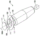
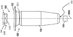
FIG. 3A is an exploded perspective view of an embodiment of a treatment device;
3B-3C are exploded side views of the treatment device of FIG. 3A;
3D-3E are top and bottom views, respectively, of the treatment device of FIG. 3A;
FIG. 3F is a side cross-sectional view of the treatment device of FIG. 3A;
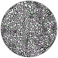
FIG. 4A shows a view of a porous structure configured for sustained release with a therapeutic device described herein;
FIG. 4B shows a view of a porous structure configured for sustained release with a therapeutic device having a10 micron coating as a barrier layer on the porous structure;
figure 4C shows a view of a porous structure configured for sustained release with an implantable device having a 20 micron coating as a barrier layer on the porous structure;
FIG. 4D shows a schematic of a porous structure configured for sustained release with an implantable device having a coating as a barrier layer on the porous structure;
FIG. 5 is a still frame capture of a filled video recording of a treatment device with a coated porous structure compared to a treatment device with an uncoated porous structure;
FIG. 6 is a flow chart showing a method of manufacturing a therapeutic device having a porous structure configured for sustained release of a therapeutic agent;
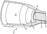
FIG. 7A is a partial cross-sectional view of the distal end region of the treatment device;
fig. 7B-7D are partial cross-sectional views of the distal region of a treatment device having a tandem porous structure.
Detailed Description
Therapeutic devices for sustained release drug delivery are described herein. The device includes one or more porous structures for delivering one or more therapeutic agents for treating a disease. The devices and systems described herein can deliver therapeutic agents to selected body regions and structures over multiple time periods. The therapeutic devices and systems described herein may be used for sustained drug delivery of one or more therapeutic agents. The therapeutic device may include a refillable reservoir configured to receive a bolus injection (bolus injection) of a therapeutic agent. The reservoir may have an outlet for delivering a bolus of the therapeutic agent from the reservoir to the patient over an extended period of time. The device may comprise a porous structure connected near the outlet of the reservoir. The porous structure may be formed of a sintered material, and will be described in more detail below. The device may comprise a barrier layer connected to the reservoir on or adjacent a surface of the porous structure, thereby allowing therapeutic agent to pass through both the porous structure and the barrier layer when delivered from the reservoir through the outlet. The porous structure is adapted to deliver the therapeutic agent at a predetermined diffusion rate, and the barrier layer is adapted to retain particles having an average particle size range that is different from or outside the average particle size range retained by the porous structure. Thus, the barrier layer is configured to prevent contaminants from entering the eye through the porous structure, or prevent contaminants from entering the reservoir through the porous structure, or both. Contaminants may vary, including, for example, one or more microorganisms, bacteria, fungal spores, immune cells, cellular products such as antibodies. The barrier layer may also mitigate rapid release of therapeutic agent as pressure within the reservoir increases.
Unless defined otherwise, all technical and scientific terms used herein have the same meaning as commonly understood by one of ordinary skill in the art. Unless otherwise indicated, all patents, patent applications, published applications and publications, websites and other published materials referred to throughout the disclosure herein are incorporated by reference in their entirety. If there are multiple definitions of terms herein, the definitions in this section prevail. Where a URL or other such identifier or address is mentioned, it will be appreciated that such identifiers may vary and that the particular information on the internet may vary, but equivalent information is known and readily accessible, such as by searching the internet and/or an appropriate database. Reference thereto evidences the availability and public dissemination of the information.
As used herein, relative directional terms such as anterior, posterior, proximal, distal, lateral, medial, sagittal, coronal, transverse, and the like are used throughout the present disclosure. The terminology is for the purpose of describing the devices and features of the devices and is not intended to be limiting. For example, as used herein, "proximal" generally means closest to the user implanting the device and farthest from the target implantation location, while "distal" means farthest from the user implanting the device in the patient and closest to the target implantation location.
As used herein, a disease or disorder refers to a pathological state in an organism caused by, for example, an infection or genetic defect, and which is characterized by identifiable symptoms.
As used herein, treating means any manner of ameliorating or otherwise beneficially altering the symptoms of a condition, disorder, or disease. Treatment also encompasses any medical use of the devices described and provided herein.
As used herein, ameliorating or alleviating a symptom of a particular disorder, e.g., by administering a particular pharmaceutical composition, refers to any alleviation, whether permanent or temporary, persistent or transient, that may be attributed to or associated with administration of the composition.
As used herein, an effective amount of a compound for treating a particular disease is an amount sufficient to ameliorate or somehow alleviate symptoms associated with the disease. Such an amount may be administered as a single dose or may be administered according to a regimen whereby it is effective. This amount can cure the disease, but is usually administered to ameliorate the symptoms of the disease. Repeated administrations may be required to achieve the desired improvement in symptoms. Pharmaceutically effective amount, therapeutically effective amount, biologically effective amount, and therapeutic amount are used interchangeably herein to refer to an amount of a therapeutic agent sufficient to achieve a desired result, i.e., a therapeutic effect (whether quantitative or qualitative). In particular, an in vivo pharmaceutically effective amount is an amount that results in the reduction, delay, or elimination of an undesirable effect (e.g., pathology, clinical, biochemical, etc.) in a subject.
As used herein, sustained release encompasses release of an effective amount of an active ingredient of a therapeutic agent for an extended period of time. Sustained release may encompass first order release of the active ingredient, zero order release of the active ingredient, or other release kinetics, such as mid to zero order and first order, or combinations thereof. Sustained release may encompass controlled release of the therapeutic agent via passive molecular diffusion driven by a concentration gradient across the porous structure.
As used herein, a subject includes any animal for which diagnosis, screening, monitoring or treatment is desired. Animals include mammals, such as primates and domestic animals. An exemplary primate is a human. Patient refers to a subject, such as a mammalian, primate, human or livestock subject, suffering from or at risk of a disease condition to be determined.
As used herein, a therapeutic agent referred to by trade name encompasses one or more of: a formulation of a therapeutic agent marketed under the trade name, an active ingredient of a marketed formulation, a common name for an active ingredient, or a molecule comprising an active ingredient. As used herein, therapeutic agents (a thermal or thermal agents) are agents that ameliorate a symptom of a disease or disorder or ameliorate a disease or disorder. Therapeutic agents, therapeutic compounds, treatment regimens, or chemotherapeutic agents include conventional drugs and drug therapies, including vaccines, which are known to those skilled in the art and described elsewhere herein. Therapeutic agents include, but are not limited to, moieties that can be controllably and sustainably released into the body.
As used herein, a composition refers to any mixture. It may be a solution, suspension, emulsion, liquid, powder, paste, aqueous, non-aqueous or any combination of these ingredients.
As used herein, fluid refers to any composition that can flow. Fluids thus encompass compositions in the form of semisolids, pastes, solutions, aqueous mixtures, gels, lotions, creams, and other such compositions.
As used herein, a kit is a packaged combination, optionally including instructions for using the combination and/or other reactions and components for such use.
As used herein, "nano (nano)", "nano-sized", "nano-scale", "nano-particle", or "nano-channel" refers to an average particle size or average particle size of less than about 1000nm, particularly less than about 200nm, more particularly between about 1nm and about 100 nm. As used herein, "micro", "micro-sized", "micro-scale", "micro-particle" or "micro-channel" relates to an average particle size or mean particle size of less than about 1000 μm, in particular less than about 200 μm, more in particular between about 1 μm and about 100 μm. In some cases, the dimensions provided herein in microns are less than 1 μm (e.g., 0.2 microns or 200 nm). Thus, "nano" and "micro" as used herein to refer to dimensions are not necessarily mutually exclusive.
The devices and systems described herein may incorporate any of the various features described herein, and elements or features of one embodiment of the devices and systems described herein may be alternatively incorporated, or in combination with elements or features of another embodiment of the devices and systems described herein and various implants and features described in U.S. patent No. 8,399,006, U.S. patent No. 8,623,395, PCT patent publication No. WO 2012/019136, PCT patent publication No. WO2012/019047, and PCT patent publication No. WO 2012/065006. For example, the porous structures described herein may be used with any of the various embodiments of a device or system. For the sake of brevity, although various combinations will be considered herein, explicit descriptions of each of these combinations may be omitted. Additionally, various methods for implanting and accessing devices are described herein. The various implants may be implanted, filled, refilled, etc. according to various methods and using various devices and systems. Some representative descriptions of how the various devices are implanted and accessed are provided, but explicit descriptions of each method with respect to each implant or system may be omitted for the sake of brevity.
The porous structures (also referred to herein as release control elements, RCEs, frits, filters, membranes or matrices) as described herein may be used with a wide variety of different implantable therapeutic devices including one or more of those described in U.S. patent No. 8,399,006, U.S. patent No. 8,623,395, PCT patent publication No. WO 2012/019136, PCT patent publication No. WO2012/019047 and PCT patent publication No. WO 2012/065006, the entire disclosures of which are incorporated herein by reference.
The porous structures described herein may be incorporated into implantable therapeutic devices that are positioned at various locations in the body. The devices and systems described herein may be used to deliver therapeutic agents to one or more of the following tissues over an extended period of time: intraocular, intravascular, intraarticular, intrathecal, pericardial, intraluminal, intraperitoneal, central nervous system, intraosseous, intramuscular, intradermal, intralesional, intraarterial, and the like. The devices and systems described herein may be used to deliver one or more therapeutic agents, either locally or systemically.
Although specific reference may be made below to delivering therapy to a particular region of the body, such as the eye or another region, it should also be understood that delivering therapy to other regions of the body to treat various medical conditions other than ocular conditions is contemplated herein. For example, conditions that may be treated and/or ameliorated using the drug delivery devices and methods described herein may include at least one of: hemophilia and other blood disorders, growth disorders, diabetes, leukemia, hepatitis, renal failure, HIV infection, Alzheimer's disease, hereditary diseases such as cerebrosidase and adenosine deaminase deficiency, hypertension, septic shock, autoimmune diseases such as multiple sclerosis, Grave's disease, systemic lupus erythematosus and rheumatoid arthritis, shock and wasting disorders (walking disorders), cystic fibrosis, lactose intolerance, Crohn's disease, inflammatory bowel disease, gastrointestinal or other cancers, degenerative diseases, trauma, multiple system diseases such as anemia, and ocular diseases (e.g., retinal detachment, proliferative retinopathy, proliferative diabetic retinopathy), degenerative diseases, vascular diseases, occlusion, infection by penetrating traumatic injury, inflammatory bowel disease, gastrointestinal or other cancers, degenerative diseases, trauma, multiple system diseases such as anemia, and ocular diseases such as retinal detachment, proliferative retinopathy, proliferative diabetic retinopathy, degenerative diseases, vascular diseases, occlusion, infection by penetrating traumatic injury, Endophthalmitis such as endogenous/systemic infection, post-surgical infection, inflammation such as posterior uveitis, retinitis, or choroiditis, and tumors such as neoplasms (neoplasms) and retinoblastoma, angiogenesis, neoplasms, abnormal new cell growth, cancerous growth, tumors, and the like. Any number of drug combinations may be delivered using any of the devices and systems described herein.
The release of the therapeutic agent from the therapeutic device may follow Fick's Law of Diffusion, which produces a decay in the release rate that follows a first order curve. Fig. 1 shows a hypothetical example of a Fickian release profile, and fig. 2 shows a corresponding plot of drug concentration in a target body location (e.g., the vitreous of the eye). In general, the therapeutic device can maintain therapeutic levels of the drug at the target body location for an extended period of time. Typically, the therapeutic device has a first order release rate profile. However, in order to maintain the desired therapeutic level even at a later point in time, the device is "tuned" to release a therapeutic level that is higher than at an earlier point in time. An alternative release mechanism by diffusion may be effective to slow the early drug release beyond that required for therapeutic benefit. For example, the rate of molecular diffusion can be inhibited by limiting the size of the pores through which the drug molecules pass, also referred to as "limiting diffusion". In a limited diffusion system, a high concentration gradient may exist and be maintained. Such systems can be "tuned" to release at a more balanced therapeutic target rate. Ideally, the therapeutic device has a "zero order" release rate rather than a first order release, such that it is released continuously at a rate to maintain a target volume concentration of drug slightly above therapeutic levels. The various materials may have a molecular-to-pore size ratio suitable for producing a diffusion-limited release rate profile. Incorporation of these materials into therapeutic devices may be feasible, but may require explicit assessment and iterative development for each molecular/clinical target of interest.
Implantable therapeutic devices contemplated herein can include a hollow, non-porous, or impermeable housing having an inner surface that at least partially defines a reservoir for containing a therapeutic material. The implantable therapeutic device can also include one or more porous structures for controlled sustained release of the therapeutic agent from the reservoir by passive molecular diffusion driven by a concentration gradient across the porous structures.
Fig. 3A-3F illustrate one embodiment of an implantable therapeutic device 100 having a hollow housing 130, a reservoir 160 for containing a therapeutic material, and one or more porous structures 150 for controlled sustained release of the therapeutic material from the reservoir 160. It should be understood that the configuration of the treatment device 100 may vary, and that the device 100 shown is merely one embodiment. The housing 130 may have a proximal region and a distal region. The housing 130 may extend along the longitudinal axis 100A between the proximal and distal regions such that the reservoir 160 is symmetrically disposed about the axis. The reservoir 160 may also be disposed eccentrically about this axis. The reservoir 160 may be a fixed volume chamber or an expandable chamber. The reservoir 160 may have a non-porous, impermeable wall adapted to contain one or more therapeutic materials or agents (see fig. 3F). The penetrable barrier 140 may be positioned within the proximal region of the housing 130, such as within an opening 180 in the access portion of the device that leads to the storage chamber 160 of the device. The porous structure 150 may be positioned in another area of the housing 130, away from the penetrable barrier 140, such as within an opening 152 of a storage chamber 160 of the lead-through device. For example, the porous structure 150 may be positioned near a distal region of the housing 130 opposite the location of the more proximal penetrable barrier 140. It will also be appreciated that additional porous structures may be provided along the housing, for example the distal end of the housing may comprise the first porous structure, and one or more additional porous structures may be provided along a portion of the housing near the distal end, for example along a tubular sidewall of the housing. The volume of the reservoir chamber 160 can be sized to deliver a therapeutic amount of the therapeutic agent to the eye over an extended period of time, and the porous structure 150 can be configured to release the therapeutic agent contained within the reservoir chamber 160 over an extended period of time, as will be described in more detail below.
The housing 130 may include a retention structure 120, which may protrude outwardly from a proximal region of the housing 130. The access portion opening 180 may be an opening in the device 100 that extends into the storage chamber 160. The penetrable barrier 140 may be positioned at least partially within the access portion opening 180 such that it forms a seal with the proximal region of the housing 130 and also allows for refilling or flushing of the device.
Referring again to fig. 3A-3F and as described above, the distal region of the housing 130 may include another opening 152, e.g., positioned near the distal region of the housing 130 opposite the proximal access portion opening 180 into the reservoir chamber 160, the other opening 152 extending out of the housing 130 between the interior of the reservoir chamber 160. The porous structure 150 may be at least partially connected to the opening 152 or positioned within the opening 152. The porous structure 150 may be secured, for example, with glue or other material, within an opening 152 at the distal end of the housing 130. Alternatively or in combination, the distal end of the housing 130 may include an inner diameter sized to accept the porous structure 150, and the housing 130 may include a stop to position the porous structure 150 at a predetermined location on the distal end so as to define a predetermined size of the reservoir 160. It should be understood that the porous structure 150 may be connected to or positioned within other regions than the distal region of the housing 130. It should also be understood that more than one porous structure 150 may be connected to the housing 130, positioned within the housing 130, or disposed along the housing 130. For example, the distal end of the housing 130 may include a first porous structure, and one or more additional porous structures may be disposed along a portion of the housing near the distal end, such as along a tubular sidewall of the housing. The one or more additional porous structures may be arranged in series such that the treatment device 100 has a first porous structure 150 that serves as a release control element to meter the diffusion of the therapeutic agent from the reservoir chamber and a second porous structure that provides a barrier function, for example by trapping immune cells, bacterial cells and other unwanted substances within the reservoir and restricting or preventing these contaminants from flowing out of the reservoir and into the eye. Additionally or alternatively, the second porous structure may provide a barrier function that limits or prevents contaminants from entering the device from within the eye. A first type of porous structure may be positioned in series with another type of porous structure. For example, sintered release control elements having a particular thickness, porosity, and tortuosity may be positioned adjacent to filter membranes having different thicknesses, porosities, and/or tortuosity. The first type of porous structure may be positioned in the distal opening of the reservoir chamber, and the filter may be bonded on an inner surface of the porous structure, an outer surface of the porous structure, or both the inner and outer surfaces of the porous structure.
Still referring to fig. 3A-3F, the therapeutic agent injected into the device 100 may be released from the reservoir 160 according to the volume of the reservoir 160 and the release characteristics or release rate index of the porous structure 150, which is described in more detail herein. The volume of reservoir 160 may be sized to deliver a therapeutic amount of therapeutic agent to a patient over an extended period of time. The volume of the reservoir 160 may be substantially determined by the internal cross-sectional area of the housing 130, e.g., the distance between the proximal penetrable barrier 140 and the porous structure 150.
One or more regions of housing 130 of the devices described herein may be formed of a substantially rigid biocompatible material. In some embodiments, the walls of housing 130 including at least proximal retention structure 120 down to and including porous structure 150 are substantially rigid such that reservoir 160 has a substantially constant volume when the therapeutic agent is released from the device in order to maintain a stable release rate profile, for example, as the patient moves. Reservoir 160 may remain substantially rigid and have a substantially constant volume even during the injection of a therapeutic agent into a device (e.g., a device that has been implanted in a patient). It should be understood that the treatment devices described herein may be incorporated into the expandable storage chamber 160, such as described in U.S. publication No. 2016/0128867, which is incorporated herein by reference.
One or more regions of shell 130, one or more regions of entrapment structure 120, and other portions of the devices described herein, individually or in combination, may be formed from one or more of a number of biocompatible materials, including but not limited to, for example, the following materials: acrylate, polymethylmethacrylate, siloxane, metal, titanium stainless steel, polycarbonate, Polyetheretherketone (PEEK), polyethylene terephthalate (PET), polyimide, polyamide-imide, polypropylene, polysulfone, polyurethane, polyvinylidene fluoride, polyphenylenepolyphenylsulfone or PTFE, among others. The material may also comprise a biocompatible light transmissive material, such as one or more of acrylate, polyacrylate, methyl methacrylate, polymethyl methacrylate (PMMA), polycarbonate, glass or silicone.
The reservoir 160 can be filled and refilled as needed, for example, after the device is implanted in a patient. As described above, the penetrable barrier 140 may be positioned at least partially within the access portion opening 180, thereby sealing the storage chamber 160 over the proximal region of the device 100. The penetrable barrier 140 may be a septum configured to receive and be repeatedly penetrated by a sharp object, such as a needle, to inject a therapeutic agent into the storage chamber 160. The penetrable barrier 140 may be configured to reseal when a sharp object is removed. The penetrable barrier 140 may be a pre-molded soft high-strength material. In some embodiments, the penetrable barrier 140 may be formed from one or more elastic materials, such as Silicone, rubber, or another liquid injection molded Silicone elastomer, such as NUSIL MED-4810, NUSIL MED-4013, etc. (NuSil Silicone Technology, Carpinteria, Calif.). In some embodiments, the penetrable barrier 140 may comprise an opaque material and/or a colored material such that it may be seen by a treating physician. In other embodiments, the penetrable barrier may be a translucent material such that when the therapeutic device is implanted in the eye and viewed by an attending physician from outside the eye, the penetrable barrier appears dark. The dark areas form penetration targets for device refilling while the device is still implanted in the eye.
As described above, the implantable therapeutic device 100 can include a porous structure 150 for controlled release of the therapeutic agent from the reservoir 160. The porous structure 150 may allow for controlled release of the therapeutic agent via passive molecular diffusion driven by a concentration gradient across the porous structure 150. Porous structures contemplated herein are described in U.S. patent No. 8,399,006, U.S. patent No. 8,623,395, PCT publication No. WO 2012/019136, PCT publication No. WO2012/019047, and PCT publication No. WO 2012/065006, the entire disclosures of which are incorporated herein by reference.
Fig. 3A-3C, 3F, and 4A-4D illustrate embodiments of a porous structure 150 configured to release a therapeutic material from a reservoir 160. The porous structure 150 may be configured in a number of ways to release the therapeutic agent according to a desired release profile. The porous structure 150 may include one or more of the following: a permeable membrane, a semi-permeable membrane, a material having at least one pore disposed therein, a nanochannel etched in a rigid material, a laser etched nanochannel, a capillary channel, a plurality of capillary channels, one or more tortuous channels, a tortuous microchannel, a sintered nanoparticle, an open cell foam, or a hydrogel such as an open cell hydrogel. The porous structure 150 may be a release control element configured to meter drug delivery to a patient.
In some embodiments, the porous structure 150 may be composed of interconnected material particles or powders. Micro-spaces or void spaces may extend throughout the porous structure 150 between the sintered materials. Void spaces within the sintered material may contribute to the porosity of the porous structure 150. Without limiting the present disclosure to any particular theory or mode of operation, the porous structure 150 may be designed to have a pore size that retains or inhibits molecules, cells, or solid particles of a particular size range from passing through and allows molecules, cells, or solid particles of another size range to pass through the porous structure 150. Porous structures may be described herein as having an average pore size or void space size to define porous structure utility to allow or substantially restrict the passage of molecules through the porous structure. In this way, molecules (e.g., therapeutic agents) of a particular size range can passively diffuse outward from within the reservoir 160 within the porous structure along a concentration gradient from one side of the porous structure 150 to the other side of the porous structure 150, such that a therapeutic amount of the therapeutic agent is delivered over an extended period of time.
The material forming the porous structure 150 may include a sintered material including at least one of metal, ceramic, glass, or plastic. The sintered material may comprise a sintered composite material, and the composite material may comprise two or more of a metal, a ceramic, a glass, or a plastic. The metal may include at least one of Ni, Ti, nitinol (nitinol), stainless steel (including alloys such as 304, 304L, 316 or 316L, cobalt chromium alloy (cobalt chrome), elgiloy, hastelloy, c-276 alloy or nickel 200 alloy). The plastic may include a wettable coating to inhibit bubble formation in the channel, and the plastic may include at least one of Polyetheretherketone (PEEK), polyethylene, polypropylene, polyimide, polystyrene, polycarbonate, polyacrylate, polymethacrylate, or polyamide.
In some embodiments, the porous structure 150 is formed from an all metal filter media. The all-metal filter media may be metal fiber or metal powder based media. In some embodiments, the powder or granules of material used to form the porous structure 150 may have an average size of no more than about 20 μm or no more than about 10 μm, an average size of no more than about 5 μm, or an average size of no more than about 1 μm, or an average size of no more than about 0.5 μm. The all-metal filter media may be a sintered porous metal media (Mott Corporation, Farmington, CT). The filter media may be of a grade that substantially prevents solid particles having a nominal solid particle size from penetrating the media. In some embodiments, the sintered material includes material particles corresponding to a Media Grade (Media Grade) of no more than about 0.1, or no more than about 0.2, or no more than about 0.3, or no more than about 0.5 (such as a Media Grade determined by ISO 4003 or ASTM E128). In some embodiments, the starting raw material for the porous structure 150 may be metal powder particles sintered together. Depending on the desired powder particle size distribution, the particle size distribution of the starting raw material may be between about 50nm and about 350nm or between about 50nm and about 50 μm and any number of microns therebetween. In other embodiments, the particle size distribution of the starting raw material may be no more than about 20 μm, no more than about 10 μm, no more than about 5 μm, no more than about 1 μm or no more than about 0.5 μm, or no more than about 0.3 μm, or no more than about 0.2 μm.
In some embodiments, the sintered material allows for the passage of solid particles having a size of about 0.1 microns or less, about 0.2 microns or less, about 0.3 microns or less and about 0.5 microns or less during filtration. In some embodiments, the pores of porous structure 150 have a diameter or pore size of about 0.2 μm, 0.3 μm, 0.4 μm, 0.5 μm, 1 μm, 2 μm, 3 μm, 4 μm, or 5 μm. In some embodiments, porous structure 150 has an average pore size of about 5 μm to about 50 μm. In some embodiments, the porous structure 150 allows passage of particles having a size less than the range of 0.1 μm to 100 μm, and largely prevents passage of particles having a size greater than this size range. The pores of the porous structure 150 may be significantly larger than the molecule of interest to be diffused through the porous structure 150. For example, the pores of the porous structure 150 may be 2, 5, 10, 15, 20, 25, 30, 35, 40, 45, 50, 75, or 100 times larger than the molecule of interest to be diffused through the porous structure 150. In some embodiments, therapeutic compounds in the IgG (150kDa or 10.5nm hydrodynamic diameter) or BSA (69kDa or 7.2nm hydrodynamic diameter) size range can diffuse relatively easily through the void spaces of porous structure 150. Pore size may represent the size of the void space extending throughout the porous structure 150. However, it should be understood that some regions within the void space may be necked down to a smaller size than adjacent holes or may be enlarged to a larger size than adjacent holes. Generally, as used herein, average pore size refers to the size of the porous structure 150, which provides information as to whether particles of a particular size range can largely pass through the porous structure 150 or be largely trapped, blocked, and/or rejected by the porous structure 150.
The porous structure 150 may have a fixed tortuous porous material, such as a sintered metal, sintered glass, or sintered polymer having a defined porosity and tortuosity that controls the rate of delivery of the at least one therapeutic agent to the target body. The void spaces within the porous structure 150 may be characterized as having a plurality of channels (e.g., microchannels and/or nanochannels) extending between the pores or openings in the first side and the pores or openings in the second side. The diameter of the channels may have a size span that allows molecules of a particular size to be attenuated or prevented from moving through them. In some embodiments, the diameter of the channel is from about 10nm span to about 1000nm span or greater. The passage may be substantially straight or may be tortuous. The percentage of porosity or void space throughout the porous structure 150 may range from about 3% to about 70%. In other embodiments, the percentage of porosity or void space ranges from about 5% to about 10% or from about 10% to about 25%, or for example from about 15% to about 20%. Porosity can be determined by weight and macroscopic volume, or can be measured by nitrogen adsorption.
Microorganisms including bacterial and/or fungal spores, as well as immune cells and cellular products such as antibodies, can be inhibited from filtering through the void spaces within the sintered material of the porous structure 150. For example, the pore size or dimension of the channels through the porous structure may have a specific small dimension range that retains this material. In some embodiments, the pore size of the porous structure 150 is, for example, 3 to 5 microns, or 3 to 10 microns, up to about 50 microns. However, pore sizes in this range may allow some microorganisms to pass through the porous structure 150. If microorganisms are inadvertently introduced into the storage chamber 160 of the implantable device 100, the microorganisms may eventually pass through the device into the surrounding tissue area of the patient. In addition, if bacteria is present in the eye of a patient from another source unrelated to the implant, it may infiltrate the implant during diffusion. Thus, a range of pore sizes can pose a risk of infection to the patient. Microorganisms as well as immune cells (e.g., macrophages), cellular products, or other molecules from the patient, bacteria, may enter the reservoir 160 through the porous structure 150 having a range of pore sizes. Porous structures with pore sizes of about 0.2 microns or less typically inhibit microbial and immune cell infiltration. However, a porous structure 150 having pore sizes in this range may inhibit the targeted release rate of the therapeutic agent from the reservoir. Furthermore, implantable therapeutic devices having a porous structure may release an amount of drug through the porous structure during in situ filling or refilling due to a transient increase in pressure inside the device that is related to the resistance of the fluid being forced through the refill needle system. In the case of a therapeutic device that has been implanted in a patient prior to filling, such rapid release of the drug during filling may be undesirable. It may be useful to control whether and how much of the filling process is released quickly.
As will be described in greater detail below, the therapeutic devices described herein can incorporate a porous barrier 155 that allows passage of a therapeutic agent of interest but inhibits microbial and cellular infiltration. As will be described in more detail below, porous barrier layer 155 may also mitigate rapid release during refilling of the reservoir by providing a dense pressure barrier. Mitigating rapid release may be useful, for example, during flushing of devices that show signs of contamination. The reservoir of the device may be flushed with an antimicrobial agent (or other type of medication) before refilling the device with a therapeutic agent for treating an ocular disease without fear of pushing contaminants into the eye.
As described above, barrier layer 155 may be a separate porous structure positioned in series with another porous structure. Each porous structure 150 may be configured to release the therapeutic agent over an extended period of time while having a particular diffusion characteristic. One or more porous structures 150 connected together in series may be connected together in any of a variety of configurations. For example, the first porous structure 150 may be positioned inside the reservoir 160, proximate to the opening 152 leading out of the reservoir 160, and the second porous structure may be positioned within the opening 152. Alternatively, the first porous structure 150 may be positioned within the opening 152 and the second porous structure may be positioned at a distal end of the first porous structure 150 outside the reservoir 160. In either form, two porous structures positioned in series may be in direct contact with each other or may be separated from each other by a distance. The porous structures positioned in series may be two or more porous structures formed of the same material or different materials. Porous structures positioned in series generally have different porosities because the first porous structure retains molecules having a size range that is not retained by the second porous structure. For example, the first porous structure may have a porosity that allows bacterial cells to penetrate therethrough, and the second porous structure may have a porosity that limits or substantially prevents molecules within this size range from penetrating therethrough. However, each of the first and second porous structures will allow the therapeutic agent to be delivered to the patient to penetrate at a predictable diffusion rate. In some embodiments, first porous structure 150 may be a sintered release control element and barrier layer 155 may be a separate filter membrane formed of a different material. The release control element may have certain defined parameters, such as thickness, area, porosity, tortuosity, and allow for drug delivery according to a particular release rate index as described elsewhere herein. The filter membrane may have defined parameters different from the release control element, whereby the filter membrane acts as a barrier to certain molecules but has minimal effect on the release rate index of the release control element. For example, the filter membrane may have a significantly smaller thickness than the release control element. The filter membrane may have a smaller porosity and/or tortuosity. In any event, the combination of the release control element and the filter membrane can maintain a particular release rate index as if the filter membrane were not present.
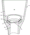
Fig. 7A shows the distal end of one embodiment of treatment device 100. The device 100 has a hollow housing 130 having walls formed of impermeable material and defining a reservoir 160 for containing a therapeutic material. A first porous structure 150 for sustained release of a therapeutic material from a reservoir 160 is positioned within an opening 152 leading out of the reservoir 160. Fig. 7B shows the distal end of the treatment device of fig. 7A having a barrier layer 155 formed of a separate porous structure connected in series with the first porous structure 150 within the reservoir 160. The barrier layer 155 in this embodiment may be a filter membrane separate from the first porous structure 150.
Still referring to fig. 7B, the chamber 160 may taper toward the opening 152 such that a region 162 is formed at the distal end of the reservoir 160 that has a narrower diameter than a more proximal region of the reservoir 160. A distal ledge 164 may surround the opening 152 in which the porous structure 150 is positioned. Barrier layer 155 may be positioned in a region 162 between porous structure 150 within opening 152 and a distal region of reservoir 160. Distal ledge 164 surrounding opening 152 may be sized to receive peripheral edge 157 of barrier layer 155 such that a central region of barrier layer 155 is aligned with opening 152, and thus porous structure 150, positioned within opening 152. Barrier layer 155 may be held in place by a bushing 158 or capture ring. Bushing 158 may be positioned over peripheral edge 157 of barrier layer 155, thereby capturing barrier layer 155 on distal ledge 164. Bushing 158 may be an annular member formed from PMMA. Inner bore 159 of bushing 158 allows communication between reservoir 160 and barrier layer 155. The outer surface of the bushing 158 may be shaped to conform to the inner wall 130 of the reservoir 160 in which it is located. The outer surface of the bushing 158 may be generally cylindrical to fit within a region 162 at the distal end of the reservoir 160. Fig. 7C shows another embodiment of treatment device 100 having barrier layer 155 captured by liner 158. In this embodiment, barrier layer 155 is positioned within the distal end of reservoir 160, and the outer surface of annular bushing 158 captures peripheral edge 157 of barrier layer 155 on wall 130 of reservoir 160 and on a distal ledge 164 formed around opening 152. Thus, the diameter of barrier layer 155 in such an embodiment may be greater than the inner diameter of the distal end of reservoir 160. The outer surface of bushing 158 may be shaped to conform to inner wall 130 of reservoir 160 such that bushing 158 may be embedded and press fit into reservoir 160 to capture peripheral edge 157 of barrier layer 155.
Fig. 7D shows the distal region of the reservoir chamber 160 of the treatment device 100 with a double liner 158. Peripheral edge 157 of barrier layer 155 may be captured between two bushings 158a, 158 b. As with other embodiments, a distal ledge 164 may be formed from the storage chamber 160 around the opening 152. The double bushing may include a first bushing 158b positioned against the distal ledge 164 and a second bushing 158a positioned toward the storage chamber 160. Peripheral edge 157 of barrier layer 155 may be captured between first bushing 158b and second bushing 158b such that a central region of barrier layer 155 is positioned over opening 152. Each of first bushing 158a and second bushing 158b may be annular or ring-shaped such that they may capture peripheral edge 157 therebetween while maintaining a central region of barrier layer 155 in free communication with reservoir 160. The ring may have any of a variety of shapes. Each double bushing may have a generally cylindrical annulus, such as bushing 158 shown in fig. 7B. The double liner may be toroidal (toroid-shaped) or other circular, such as liner 158 shown in fig. 7C. The annulus of each double liner may also have a frustoconical shape, a funnel shape, a toroidal coil shape (toroid), a flattened toroidal coil shape (flattened toroid), or a bowl shape. Peripheral region 157 may be captured between the flat sides of the ring and the central region of barrier layer 155 may be aligned with the central bore of bushing 158. The double bushing 158 may be pre-fused and bonded in place with an adhesive or solvent.
It should be understood that barrier layer 155 may be positioned relative to porous structure 150 such that it is positioned on the reservoir side of porous structure 150 or on the reservoir and the outside of porous structure 150. Barrier layer 155 may be positioned in contact with porous structure 150, for example, as shown in fig. 7B, or barrier layer 155 may be spaced apart from porous structure 150, for example, as shown in fig. 7D. It should also be understood that barrier layer 155 may be attached to the device using any of a variety of techniques. Barrier layer 155 may be heat fused, ultrasonically bonded, or adhered. Further, barrier layer 155 may be formed from any of a variety of materials, including porous metals as described elsewhere herein. In some embodiments, barrier layer 155 may be a disk filter formed from silver metal, cellulose acetate, ceramic, glass fiber, borosilicate fiber, MCE (mixed cellulose ester), nylon, Polyacrylonitrile (PAN), polycarbonate track etch (PCTE), Polyethersulfone (PES), polyester track etch (PETE), polypropylene (PP), PTFE, PVDF, or other filter materials such as those provided by Sterlitech Corp.
Whether a separate porous structure such as the filter membrane described above or a coating on the porous structure, barrier layer 155 may contain contaminants that are introduced into the system to prevent expulsion into the eye and/or to limit or substantially prevent the entry of contaminants from the eye into the system. Contaminants may be introduced into the system when the reservoir is initially filled with the therapeutic agent or refilled while the therapeutic device is still implanted in the eye. Barrier layer 155 may limit or prevent the release of these contaminants from reservoir 160 into the eye, thereby at least reducing the risk of infection of the eye until the contaminants are identified and the treatment device can be removed from the eye. In some embodiments, barrier layer 155 may limit or prevent the passage of contaminants from the reservoir into the eye for at least about 1 week, 1 month, or indefinitely. Contaminants can cause changes in the appearance of the contents of the storage chamber (e.g., cloudiness) or cause irritation to the patient. The treatment device may be visually inspected by a physician after implantation, for example, through an indirect ophthalmoscope or on a slit lamp.
In addition to limiting reservoir contamination and reducing the risk of eye infection by containing contaminants within the system and limiting release into the eye, barrier layer 155 allows for flushing of the reservoir without removing the device from the eye. As described elsewhere herein, barrier layer 155 can mitigate rapid release through porous structure 150 during injection of fluid into the reservoir. Contamination of the reservoir may be addressed by flushing the system or injecting antibiotics into the system. Because the quick release is mitigated, irrigation and/or injection can be performed while the device is still implanted in the eye without fear of contaminants being pushed from the reservoir through the porous structure into the eye. For example, a refill needle system such as described in U.S. patent No. 9,033,911 filed on 5/8/2011 or U.S. publication No. 2013-. Once the system is disposed of, it can be further flushed with saline and the original therapeutic drug can be refilled into the system so that the patient can continue treatment.
In some embodiments, the porous structure 150 may have an average pore size of between about 0.2 μm to about 5 μm and a porosity of between about 10% to about 30%. Barrier layer 155 may have an average pore size of about 0.2 microns or less, approaching the size of the therapeutic agent being delivered. As such, barrier layer 155 retains smaller molecules than would otherwise be retained by porous structure 150. Or in other words, molecules of a particular size that are trapped or blocked by barrier layer 155 are not trapped or blocked by porous structure 150. The porosity P of barrier layer 155 may be substantially less than the porosity of porous structure 150 alone. The significantly reduced porosity of barrier layer 155 may result in an overall denser material as compared to porous structure 150. In some embodiments, barrier layer 155 may have a porosity between about 1% and about 15%. Although barrier layer 155 has smaller pore sizes and lower porosity than porous structure 150 applied in association with or in cooperation with barrier layer 155, in some embodiments, the release rate through porous structure 150 and barrier layer 155 may be maintained or comparable to the release rate through porous structure 150 alone, as if barrier layer 155 were not present. For example, the individual porous structures 150 may have a release rate index of between about 0.06mm to about 0.1 mm. In other embodiments, the porous structure 150 alone may have a release rate index as low as 0.002 and as high as 0.15. The porous structure 150 with barrier layer 155 may have a release rate index between about 0.06mm to about 0.1 mm. In other embodiments, the release rate index of porous structure 150 in the presence of barrier layer 155 may be significantly different than the release rate index of porous structure 150 alone, but certain parameters of porous structure 150 may be optimized to achieve a desired release rate index in the presence of barrier layer 155. For example, the porous structure 150 may be selected based on greater porosity or less tortuosity or less thickness, or a combination thereof.
It should be understood that the ranges provided herein are examples and that one or more features may be modified and/or optimized to achieve a desired effect in drug delivery. For example, the individual porous structures 150 prior to combination with barrier layer 155 may be selected based on their gas flow rates. The gas flow rate may vary, for example, between about 10 standard cubic centimeters per minute (sccm) to about 250 sccm. The gas flow rate can be between 1.5sccm and 320 sccm. In some embodiments, the gas flow rate can be 10, 20, 30, 40, 50, 60, 70, 80, 90, 100, 110, 120, 130, 135, 140, 145, 150, 200, 250, or 400 sccm. The release rate index (mm) of the individual porous structures 150 may be about 0.01 to about 0.10, or about 0.06 to about 0.04, or about 0.002 to about 1.5. Typically, barrier layer 155 has an average pore size equal to or less than 0.2 μm, approaching the size of the drug molecules being delivered. The average pore size of porous structure 150 may be increased relative to the average pore size of barrier layer 155. For example, the average pore size of the porous structure 150 may be between about 0.2 microns to about 9 microns. The thickness of porous structure 150 and barrier layer 155 may also vary. The porous structure 150 may have a thickness of about 70 microns to about 5000 microns and an outer diameter of about 700 microns to about 1200 microns. Barrier layer 155 may have a thickness substantially less than porous structure 150. In some embodiments, barrier layer 155 is a coating and may have a thickness of about several nanometers to about 250 micrometers. Whether a coating deposited on the surface as shown in fig. 4D or a separate structure in series with porous structure 150, barrier layer 155 may have a minimum thickness so as to effectively maintain the same thickness (length L) of porous structure 150 alone. In some embodiments, barrier layer 155 may be a filter membrane having a nominal thickness of about 10 μm to about 200 μm, or about 110 μm to about 150 μm. In some embodiments, the series combination of barrier layer 155 and porous structure (e.g., a "composite" release control element) may have a thickness greater than the thickness of the porous structure alone, while having minimal impact on the drug diffusion properties of the porous structure. Alternatively, the diffusion properties of porous structure 150 may be adjusted to remove any actual or incidental effects on drug release through the porous structure caused by barrier layer 155.
As described above with respect to porous structure 150, barrier layer 155 may be designed to have the following pore sizes: which traps or inhibits the passage of molecules, cells or solid particles of a particular size range and allows molecules, cells or solid particles of another size range to pass through barrier layer 155. Barrier layer 155 may be described herein as having an average pore size or void space size or molecular weight cut off (molecular weight cut off) to define the utility of barrier layer 155 for allowing molecules to substantially pass through barrier layer 155 or for substantially limiting or preventing molecules from passing through barrier layer 155. As such, molecules (e.g., therapeutic agents) of a particular size range may pass from one side of barrier layer 155 to the other side of barrier layer 155, causing them to be released from the reservoir.
In some embodiments, porous structure 150 may be between a media grade 0.2 and a media grade 0.5 porous material, and barrier layer 155 may be a plurality of particles having an average particle size of 50 nanometers to 350 nanometers. In some embodiments, porous structure 150 may comprise a 316L stainless steel matrix (Mott corporation), and barrier layer 155 may be a mass of particles that are primarily stainless steel. The porous matrix and the plurality of particles may be sintered. In some embodiments, a suspension of sinterable particles in a carrier fluid is applied as barrier layer 155 to substrate 150 using an ultrasonic nozzle, and the sinterable particles are sintered to substrate 150 in an ultrasonic spray deposition process. The particle suspension may be a suspension of particles applied to the porous substrate 150. The porous structure 150 may be fabricated according to the process described in U.S. patent application No. 2012/0183799, which is incorporated herein by reference in its entirety. Porous structure 150 may be a substrate having pores with a first average pore size, and barrier layer 155 may be a coating on at least one surface of the substrate and having pores with a second average pore size. The pore size of the porous structure 150 may be equal to or greater than the second average pore size. As described in more detail below, barrier layer 155 may have an average pore size effective to capture microorganisms greater than 0.2 microns, as assessed by microorganism retention ASTM F838-05 or equivalent methods.
In other embodiments, the porous structure 150 may be a sintered titanium element with a thin film titanium coating deposited by Physical Vapor Deposition (PVD) or Plasma Enhanced Chemical Vapor Deposition (PECVD) (acre Technologies inc., Concord, CA). In some embodiments of the sputtering method of forming barrier layer 155, a source target, such as a titanium target, is activated to vaporize the target material into a surrounding atmosphere, such as a vacuum environment in a plasma plume. The vapor may condense onto one or more surfaces of porous matrix 150, thereby forming barrier layer 155 in the form of a thin film. The process may be carried out in ultra-high vacuum or in the presence of a background gas such as oxygen. The chamber may include a fixture, such as a rotating basket, inside the chamber to allow all surfaces of porous structure 150 to receive the coating that forms barrier layer 155. Alternatively, a single surface of the porous structure 150 may be coated. An Energy Deposition Process (EDP) may also be used to form barrier layer 155 on porous structure 150. EDP is characterized by high ionization rates and higher added atomic energy (add-atom energy) than PVD, e.g., 50% -100% compared to about 5% for PVD. The additive atomic energy in sputtering can be between 1eV and 3eV, while for EDP the additive atomic energy can be about 30eV to about 100eV, depending on the material deposited and the process conditions. Higher ionization potentials and energies generally result in the deposition of denser films. Standard sputtering tends to produce slightly porous coatings with columnar morphology, whereas EDP tends to produce non-porous, denser coatings with no columnar structure. As noted above, the relative thicknesses of the substrate and coating may vary. In some embodiments, the porous structure 150 may be between about 700 microns to about 5000 microns, or between about 200 microns to about 1300 microns. In some embodiments, barrier layer 155 may be about 1, 2, 3, 4, 5 microns up to about 10 microns thick. In some embodiments, barrier layer 155 may be about 10, about 20, about 30, about 40, about 50, about 60, or about 70 microns thick. In some embodiments, barrier layer 155 may be between about 5 microns thick to about 40 microns thick.
A therapeutic amount of one or more therapeutic agents may pass through porous structure 150 and barrier layer 155 of the therapeutic device described herein for an extended period of time, while other particles are prevented from passing through the porous structure and/or barrier layer. The therapeutic devices described herein can have a porous structure 150 and/or a barrier layer 155 sized to pass at least one therapeutic agent having a molecule with a molecular weight of at least about 100kDa, 75kDa, 50kDa, 25kDa, 10kDa, 5kDa, 2.5kDa, 1kDa, 500 daltons (D), 250D, 200D, 150D, or 100D. Various therapeutic agents are contemplated herein. Table 1 provides representative therapeutic agents that can be delivered and their molecular weights.
The therapeutic devices described herein may have a porous structure 150 and/or barrier layer 155 sized to inhibit the passage of microorganisms. Microorganisms may include, but are not limited to, fungi, fungal spores, protists, and bacterial cells, including Brevundimonas diminuta (Brevundimonas diminuta), Propionibacterium acnes (Propionibacterium acnes), actinomycetes (actinomycetes species), Bacillus cereus (Bacillus cereus), Clostridium (Clostridium), Enterococcus (Enterococcus), Escherichia coli (Escherichia coli), Haemophilus influenzae (Haemophilus influenzae), Klebsiella pneumoniae (Klebsiella pneumoniae), Mycobacterium tuberculosis (Mycobacterium tuberculosis), Neisseria meningitidis (Neisseria meningitidis), Nocardia asteroides (Nocardia asteroides), Pseudomonas aeruginosa (Pseudomonas aeruginosa), Serratia (sartoria sp), Staphylococcus aureus (Staphylococcus aureus), Staphylococcus aureus (Staphylococcus epidermidis), Streptococcus pneumoniae (Streptococcus pneumoniae, etc.). The treatment devices described herein can have a porous structure 150 and/or a barrier layer 155 that is sized to inhibit immune cells and/or cellular material from entering the treatment device and/or exiting the treatment device from the patient. Immune cells may include, but are not limited to, monocytes, lymphocytes, neutrophils, eosinophils, basophils, macrophages, erythrocytes, platelets, and other cells. The treatment devices described herein can have a porous structure 150 and/or a barrier layer 155 sized to inhibit the passage of any of these unwanted molecules (e.g., microorganisms, cells, cellular material) while allowing one or more therapeutic agents to pass from the treatment device into the eye.
The release rate of the therapeutic agent through the individual porous structures 150 (e.g., the sintered porous metal structures described above) can be described by the following equation: release rate (D P/F) A (c)R-cv) L, wherein: c. CRConcentration in reservoir, cvD-the diffusion coefficient of the therapeutic agent in the reservoir solution, P-the porosity of the porous structure, F-the channel parameter that may correspond to the tortuosity of the channels of the porous structure, a-the area of the porous structure, and L-the thickness (length) of the porous structure. Cumulative release of 1-cR/cR01-exp ((-D PA/FL V R) t), where t is time, VrReservoir volume.
The parameters of the porous structure 150 that affect the passive molecular diffusion of the drug from the reservoir 160 due to the concentration gradient are the porosity (P), tortuosity (T), area (a), and length or thickness (L) of the porous structure 150. These parameters are covered by the Release Rate Index (RRI), which can be used to determine the release of the therapeutic agent. RRI may be defined as (PA/FL), where P is the porosity of the porous structure, a is the effective area of the porous structure, F is a curve fitting parameter corresponding to the effective length, and L is the length or thickness of the porous structure 150.
As described above, the particles of material sintered together to form the porous structure 150 may define interconnected channels through the void spaces of the porous structure 150. The channel parameter (F) may correspond to an elongation of the path of the therapeutic agent released through the porous structure 150. The porous structure 150 may include many of these interconnected channels, and the channel parameter (F) may correspond to the effective length of the therapeutic agent traveling along the interconnected channels of the porous structure 150 (e.g., from the reservoir side to the outside of the device 100).
The D of Bovine Serum Albumin (BSA) in water at 20 ℃ can be determined by the following equationBSA,20C=6.1e-7cm2Diffusion coefficient (D) was estimated from the measured values of/s (Molokhia et al, Exp Eye Res 2008): dTA,37C=D BSA,20C(η20C/η37C)(MW BSA/MW TA)1/3Where MW refers to the molecular weight of BSA or test compound and η is the viscosity of water. The small molecules have a similar structure to fluorescein (MW 330, D4.8 to 6e-6 cm)2(ii)/s, diffusion coefficient (D) from Stay, M S et al Pharm Res 2003,20(1), pages 96-102). For example, the small molecule may include a glucocorticoid, such as triamcinolone acetonide having a molecular weight of about 435.
The porous structure 150 has a porosity, thickness, channel parameters, and surface area configured to release a therapeutic amount over an extended period of time. The porosity of the porous structure 150 may be determined by weight and macroscopic volume, or may be measured by nitrogen adsorption. As described above, the porous structure 150 may include a plurality of porous structures. The area a used in the above equation may include a combined area of a plurality of porous structures.
The channel parameter (F) may be a fitting parameter corresponding to the tortuosity of the channel. For known porosity (P), surface area (a) and thickness (L) of the surface parameters, curve fitting parameters (F) that may correspond to the tortuosity of the channel may be determined based on experimental measurements. The parameter PA/FL can be used to determine the desired sustained release profile and the determined values of P, A, F and L. The release rate of the therapeutic agent corresponds to a ratio of porosity to channel parameter, and the ratio of porosity to channel parameter may be less than about 0.5, such that the porous structure releases the therapeutic agent over an extended period of time. For example, the ratio of porosity to channel parameter (F) is less than about 0.1 or, for example, less than about 0.2, whereby the porous structure releases the therapeutic agent over an extended period of time. The channel parameter (F) may be a value of at least about 1, such as at least about 1.2. For example, the value of the channel parameter (F) may be at least about 1.5, such as at least about 2, and may be at least about 5. The channel parameter (F) may be in the range of about 1.1 to about 10, for example in the range of about 1.2 to about 5. The channel parameter (F) for releasing the therapeutic agent to obtain a desired release rate profile may be empirically determined.
The area (a) in the model is derived from a description of the transport mass in flux; i.e., mass transfer rate per unit area. For simple geometries, such as a porous disc mounted in an impermeable sleeve of equal thickness, the area (a) corresponds to one face of the disc and the thickness (L) is the thickness of the disc. For more complex geometries, such as a frustoconical shaped porous structure, the effective area (a) may be a value between the area where the therapeutic agent enters the porous structure and the area where the therapeutic agent exits the porous structure.
By correlating the concentration change in the reservoir with the above-mentioned release rates, a model can be derived to describe the release rate as a function of time. The model employs a uniform concentration of therapeutic agent solution in a reservoir. In addition, the concentration in the receiving fluid is considered negligible (c)v0). Solving the differential equation and rearranging yields the following equation, which describes the concentration in the reservoir as time t and reservoir volume VRFor release from solution in the reservoir through the porous structureA therapeutic agent is put in. c. CR=c R0exp((-D PA/FL V R) t) and cumulative release ═ 1-cR/cR0。
The above model and determining the parameters in the above equation and adjusting the treatment device to release a therapeutic amount above the minimum inhibitory concentration for an extended period of time based on bolus injection of the therapeutic agent are described in more detail, for example, in US 8,399,006 (which is incorporated herein by reference).
The release rate of the therapeutic agent from the therapeutic device can be assessed by measuring the diffusion of the size-matched molecules through the porous structure in vitro over an extended period of time. For example, a solution representing the drug of interest and having a known concentration of BSA or fluorescein solution or other molecules may be used to fill the reservoir of the therapeutic device and allow diffusion from the reservoir over time through a porous structure attached to the device. The diffusion experiment may last for 1, 2, 3, 4, 5, 6, 7, 8, 9, 10 or more weeks, and samples are taken at different time points therein to assess the release rate of the therapeutic agent through the porous structure. The sample allows the cumulative amount of drug released from the device to be plotted over time. The amount of test molecule within the reservoir and/or outside the reservoir can be measured as known in the art, for example, by absorbance, fluorescence, ELISA, and other tests.
The measured release rate can be compared to a predicted release rate using the model described above, which relates the concentration change in the reservoir to the release rate from the reservoir based on fick's law of diffusion. As described in u.s.8,399,006, release from the device is consistent with the trend predicted by the model.
Porosity P may be determined by nitrogen adsorption and is typically provided by the manufacturer along with area a and length L. The measured cumulative release of molecules through the porous structure and predictions from models describing the release through the porous structure can be used to determine the channel parameter F. Thus, after determining the channel parameter F, the Release Rate Index (RRI) may be determined. The RRI is determined by fitting rate data from the device. The measured RRI may be used to determine release of the therapeutic agent, and the porous structure may be further characterized with gas flow as described herein to determine the RRI prior to placement in a patient.
The porous structure may be subjected to a gas flow test to determine the release rate of the therapeutic agent from the device. These tests can be used with the porous structure positioned on the treatment device or prior to assembly of the porous structure with the treatment device in order to quantify the flow through the porous structure of the device. The flow of a gas, such as oxygen or nitrogen, through the porous structure may be measured by the decay time of the gas pressure. The flow rate and RRI may be determined based on the material of the porous structure. The therapeutic agent may be measured by a porous structure or similar test molecule. The flow rate of the gas is empirically determined in relation to the release rate of the therapeutic agent. In some embodiments, a correlation may be established between a "flow" test that depends on a pressure gradient and is a forced gas flow and an actual drug release test that depends on passive diffusion in vitro through a porous structure. This correlation is described in more detail in US 8,399,006, which is incorporated herein by reference.
The sustained release of the therapeutic agent from the reservoir through the porous structure relies on passive, concentration gradient driven molecular diffusion. Direct measurement of this type of sustained release can be time consuming and prevents reuse of the porous structure. Thus, testing porous structures using active pressure gradient response as an alternative to characterizing passive molecular diffusion mechanisms is described. In some embodiments, a forced gas flow test involving a pressure gradient may be associated with a drug release test that relies on passive transport of a therapeutic agent diffusing from a reservoir into a target volume via tortuous, interconnected pathways through a porous structure.
The tests described herein and in U.S. patent No. 8,399,006 allow for tests that will demonstrate the performance of porous materials with respect to molecular diffusion mechanisms. Fick's molecular diffusion law states that diffusion through a porous element can be described by a linear concentration gradient across the thickness L of the element, where the diffusion coefficient is reduced by the ratio of porosity P to tortuosity T, giving the equation:

where cv is the concentration of the drug in the receiving fluid.
The elements specific to the porous structure in this equation can be isolated and incorporated into the RRI. The porous structure controls drug delivery by its macroscopic size, area and thickness as well as its microscopic properties, porosity and tortuosity. These four parameters may be combined into a single parameter, called the Release Rate Index (RRI), which has units of length and is shown below:

RRI parameters may correlate various porous structures with rapid and easy non-destructive gas flow versus pressure behavior. This allows 100% QC testing of the device to ensure long-lasting drug release performance without leaving the porous structure too wet. This also allows for correlation-based interpolation to intelligently select porous structures that do not currently exist. Furthermore, the RRI curve and understanding of device properties (e.g. reservoir volume capacity) and drug properties (e.g. drug concentration and drug molecule diffusion) allows one to design the release behavior of yet unstructured systems. This correlation allows prediction of various drug release parameters that may be of interest, such as daily release rate over time, estimated generated concentration in the target volume, cumulative amount or percentage of amount of drug released, and expected duration of efficacy for known therapeutic dose requirements.
Fig. 6 is a flow chart illustrating a method 600 of manufacturing a therapeutic device having a porous structure configured for sustained release of a therapeutic agent. It should be understood that the steps described need not be performed exactly in the order shown. A porous structure 150 having specified characteristics may be selected (block 605). The specified characteristics or parameters may include characteristics that affect the rate of diffusion of the drug through the porous structure, such as the type of material, the size of the entrapped solid particles, the porosity P, the area a, the length or thickness L, the average pore size, and the like. The specified characteristics are covered by a Release Rate Index (RRI), which can be used to determine the release of the therapeutic agent. RRI may be defined as (PA/FL), where F is a curve fitting parameter corresponding to the effective length. For example, the porous structure may be a 316L stainless steel substrate having a porosity of between about 10% -20%, a media rating of 0.2, a thickness of between about 0.50mm to about 1.50mm, an average pore size of about 3 μm to about 5 μm, up to 50 μm. A non-destructive gas flow test may be performed on the porous structure having specified characteristics (block 610) to obtain performance results. For example, the performance result may be a gas flow rate of about 100sccm to about 150 sccm. A drug diffusion test may be performed on the porous structure with specified characteristics to measure the diffusion rate of molecules through the porous structure (block 615). For example, the measured diffusion rate of Bovine Serum Albumin (BSA) through a porous structure. The measured diffusion rate of the molecule through the porous structure allows calculation of RRI. Data from the non-destructive gas flow test and the destructive gas flow test may be analyzed to generate a correlation between the two test types (block 620), the correlation being between the pressure gradient forced gas flow test and the actual drug release test, which depends on passive diffusion through the porous structure. More than one pair of test results may be used to generate the correlation. The resulting correlation may be used to predict the measured diffusivity of the molecule through a porous structure having the same specified characteristics based on the test results of the porous structure during the non-destructive gas flow test (block 625). The flow rate of the gas is thus empirically determined in relation to the release rate of the therapeutic agent. Thus, the porous structure 150 may only undergo non-destructive testing and predict the results achievable by performing destructive testing in order to quantify the diffusion of the drug through the porous structure. When the porous structure 150 is coated as described herein or combined with a barrier layer (e.g., a separate filter membrane positioned adjacent to the porous structure 150), predicting diffusion of the drug through the porous structure based on non-destructive test results remains accurate.
The barrier layer may have minimal effect on drug diffusion, whether the barrier layer is a coating or a separate filter membrane positioned in series with the porous structure. Therefore, the above-described manufacturing method can be applied regardless of whether a barrier layer is used.
The therapeutic devices described herein may be implanted so long as they are helpful and beneficial to the patient. For example, the device may be implanted for at least about 1 year, 2 years, 3 years, 4 years, 5 years, and until permanently implanted for the life of the patient. Alternatively or in combination, the device may be removed when there is no longer any help or benefit to the patient treatment. In other embodiments, the device may be implanted for at least about 4 to 10 years, for example for the duration of a treatment period for a chronic disease such as diabetic macular edema or age-related macular degeneration. The device can be periodically refilled with new therapeutic agent at the physician's office as indicated by disease progression. For diseases such as age-related macular degeneration, the device may be refilled weekly, biweekly, monthly, every two months, every 3 months, every 4 to 6 months, every 3 to 9 months, every 12 months, or at a frequency of any other period indicated for treatment of the disease.
It is understood that the devices and systems described herein can be used to treat a variety of diseases and/or conditions, such as: glaucoma, macular degeneration, retinal diseases, proliferative vitreoretinopathy, diabetic retinopathy, uveitis, keratitis, cytomegalovirus retinitis, cystoid macular edema (cystoid macular edema), herpes simplex virus and adenovirus infections, and other eye diseases, eye infections (including but not limited to skin, eyelid, conjunctival and/or lacrimal gland excretory system infections), orbital cellulitis, lacrimal gland inflammation, hordeolum, blepharitis, conjunctivitis, keratitis, corneal infiltrates, ulcers, endophthalmitis, panophthalmitis, viral keratitis, fungal keratitis, ocular herpes zoster, viral conjunctivitis, viral retinitis, uveitis, strabismus, retinal necrosis, retinal diseases, vitreoretinopathy, diabetic retinopathy, cytomegalovirus retinitis, cystoid macular edema (cystoid macular edema), Herpes simplex virus and adenovirus injection, scleritis, mucormycosis, canaliculitis, acanthamoeba keratitis, toxoplasmosis, giardiasis, leishmaniasis, malaria, helminth infection, etc. It should also be appreciated that medical conditions other than ocular conditions may also be treated with the devices and systems described herein. For example, the device may deliver drugs for treating inflammation, infection, cancerous growth. It should also be understood that any number of drug combinations may be delivered using any of the devices and systems described herein.
The devices described herein can be used to deliver one or more agents that ameliorate the symptoms of a disease or disorder or ameliorate a disease or disorder, including, for example, small molecule drugs, proteins, nucleic acids, polysaccharides, biologics, conventional drugs, and drug therapies known to those of skill in the art, including vaccines. Examples of therapeutic agents suitable for use in accordance with embodiments of the treatment devices described herein are listed in their entirety and in table 1.
Therapeutic agents include, but are not limited to, moieties that inhibit cell growth or promote cell death, moieties that can be activated to inhibit cell growth or promote cell death, or moieties that activate another agent to inhibit cell growth or promote cell death. Optionally, as described elsewhere herein, the therapeutic agent may exhibit or exhibit other properties, such as properties that allow it to be used as an imaging agent. Exemplary therapeutic agents include, for example, cytokines, growth factors, proteins, peptides or peptidomimetics, bioactive agents, photosensitizers, radionuclides, toxins, antimetabolites, signaling modulators, anticancer antibiotics, anticancer antibodies, angiogenesis inhibitors, radiation therapy, chemotherapeutic compounds, or combinations thereof. The drug may be any agent capable of providing a therapeutic benefit. In one embodiment, the drug is a known drug or combination of drugs effective in the treatment of diseases and conditions of the eye. In non-limiting exemplary embodiments, the drug is an anti-infective agent (e.g., an antibiotic or antifungal agent), an anesthetic, an anti-VEGF agent, an anti-inflammatory agent, a biological agent (e.g., RNA), an intraocular pressure-reducing agent (i.e., glaucoma drug), or a combination thereof. Non-limiting examples of drugs are provided below.
The therapeutic agent may include a macromolecule, such as an antibody or antibody fragment. Therapeutic macromolecules may include VEGF inhibitors, such as Lucentis, commercially availableTM. VEGF (vascular endothelial growth factor) inhibitorsWhen released into the vitreous humor of the eye, can cause regression of abnormal blood vessels and improvement of vision. Examples of VEGF inhibitors include LucentisTM、AvastinTM、MacugenTMAnd VEGF Trap (VEGF Trap). Therapeutic agents may include small molecules such as corticosteroids and their analogs. For example, the therapeutic corticosteroid may include one or more of triamcinolone (trimacrinone), triamcinolone acetonide (trimacrinone acetate), dexamethasone (dexamethasone), dexamethasone acetate (dexamethasone acetate), fluocinolone acetonide (fluocinolone acetonide), fluocinolone acetonide (fluocinolone acetate), or an analog thereof. Alternatively or in combination, the small molecule of therapeutic agent may comprise a tyrosine kinase inhibitor, which for example comprises one or more of axitinib (axitinib), bosutinib (bosutinib), cediranib (cediranib), dasatinib (dasatinib), erlotinib (erlotinib), gefitinib (gefitinib), imatinib (imatinib), lapatinib (lapatinib), lestaurtinib (lestautinib), nilotinib (nilotinib), semaxanib (semaxanib), sunitinib (sunitinib), trolazib (toceranib), vandetanib (vandetanib) or vatalanib (vatalanib). The therapeutic agent may include an anti-VEGF therapeutic agent. anti-VEGF therapies and agents are useful for treating certain cancers and age-related macular degeneration. Examples of anti-VEGF therapeutic agents suitable for use in accordance with embodiments described herein include one or more of: monoclonal antibodies, such as bevacizumab (Avastin)TM) Or antibody derivatives such as ranibizumab (Lucentis)TM) Or small molecules that inhibit VEGF-stimulated tyrosine kinases, e.g., lapatinib (Tykerb)TM) Sunitinib (Sutent)TM) Sorafenib (sorafenib) (Nexavar)TM) Axitinib or pazopanib (pazopanib). The therapeutic agent may include a therapeutic agent suitable for treating dry AMD, such as SirolimusTMRapamycin (Rapamycin), CopaxoneTMGlatiramer Acetate (Glatiramer Acetate)), OtheraTMOne or more of a complement C5aR blocker, ciliary neurotrophic factor, Fenretinide (Fenretinide), or plasma purification therapy (Rheopheresis). The therapeutic agent may include those suitable for treating a wet conditionTherapeutic agents for AMD, e.g. REDD14NP (Quark), SirolimusTMRapamycin, ATG003, RegeneronTM(VEGF trap) or complement inhibitor (POT-4), complement factor D inhibitor. Therapeutic agents may include kinase inhibitors, such as one or more of bevacizumab (monoclonal antibody), BIBW 2992 (small molecule targeting EGFR/Erb 2), cetuximab (cetuximab) (monoclonal antibody), imatinib (small molecule), trastuzumab (monoclonal antibody), gefitinib (small molecule), ranibizumab (monoclonal antibody), pegaptanib (small molecule), sorafenib (small molecule), dasatinib (small molecule), sunitinib (small molecule), erlotinib (small molecule), nilotinib (small molecule), lapatinib (small molecule), panitumumab (monoclonal antibody), vandetanib (small molecule), or E7080 (targeting VEGFR2/VEGFR2, small molecules commercially available from Esai, co.
The therapeutic agent may include an inhibitor of VEGF receptor kinase; VEGFA, VEGFC, VEGFD, bFGF, PDGF, VEGF/PDGF, VEGFA/Ang2, Ang-2, PDGFR, cKIT, FGF, BDGF/VEGF/FGF, mTOR, α v β 3, α v β 5, α 5 β 1 integrin, α v β 3/α v β 5/α 5 β 1 integrin, inhibitors of α 2 adrenergic receptors; complement factor B inhibitors (e.g., TA106), complement factor d (cfd) inhibitors (Lampalizumab/TNX-234), C3 inhibitors (e.g., APL-2, novel compstatin analogs), C5 inhibitors (e.g., Eculizumab, Zimura, ARC1905, ALN-CC5), C5a inhibitors (e.g., JPE-1375), and related targets; tubulin; AAV-CD 56. Therapeutic agents may also include Complement Factor H (CFH), engineered micro-CFH (engineered mini-CFH), or recombinant CFH (rcfh).
A variety of therapeutic agents can be delivered using the drug delivery implants described herein, including: anesthetics, analgesics, cell trafficking/movement inhibitors such as colchicine (colchicine), vincristine (vincristine), cytochalasin (cytochalasin) B and related compounds; anti-glaucoma drugs including beta-blockers such as timolol (timolol), betaxolol (betaxolol), atenolol (atenolol) and prostaglandins, lipid receptor agonists or prostaglandin analogs such as bimatoprost (bimatoprost), travoprost (travoprost), latanoprost (latanoprost), unoprostone (unoprostone), and the like; alpha-adrenergic agonists, brimonidine (brimonidine) or dipivefrine (dipivefrine), carbonic anhydrase inhibitors such as acetazolamide (acetazolamide), methazolamide (methazolamide), dichlorfenamide (dichlorphenamide), diamox (diamox); and neuroprotective agents such as nimodipine (nimodipine) and related compounds.
Other examples include targets that affect angiogenin and angiogenin receptors that bind to angiogenin, including but not limited to TIE-1, TIE-2, Ang1, Ang2, Ang3, Ang4, including but not limited to pazopanib (Votrient) or any other therapeutic agent described in U.S. publication No. 2014/0276482 and PCT application Ser. No. PCT/US2015/043921, each incorporated by reference herein.
Other examples include antibiotics, such as tetracycline (tetracycline), chlortetracycline (chlorotetracycline), bacitracin (bacitracin), neomycin (neomycin), polymyxin (polymyxin), gramicidin (graminidin), oxytetracycline (oxytetracycline), chloramphenicol (chlorohexinol), gentamicin (gentamycin), and erythromycin (erythromycin); antibacterial agents such as sulfonamide (sulfanamide), sulfacetamide (sulfacetamide), sulfamethizole (sulfamethiazole), and sulfisoxazole (sulfadoxazole); antifungal agents, such as fluconazole (fluconazol), nitrofurazone (nitrofurazone), amphotericin (amphotericin) B, ketoconazole (ketoconazole), and related compounds; antiviral agents, such as trifluorothymidine (triflurothymidine), acyclovir (acyclovir), ganciclovir (ganciclovir), DDI, AZT, foscarnet (foscamet), vidarabine (vidarabine), trifluridine (triflurouridine), idoxuridine (idoxuridine), ribavirin (ribavirin), protease inhibitors, and anti-cytomegalovirus agents; antiallergic agents such as methamphetamine (methapyriline), chlorpheniramine (chlorpheniramine), pyrilamine (pyrilamine), and phenylpyramine (prophenylpyrilamine); anti-inflammatory agents, such as hydrocortisone, dexamethasone, fluocinolone, prednisone, prednisolone, methylprednisolone, fluorometholone, betamethasone and triamcinolone; decongestants such as phenylephrine, naphazoline and tetrahydrozoline; miotics, muscarinic and anticholinesterases, such as pilocarpine (pilocarpine), carbachol (carbachol), diisopropyl fluorophosphate, thiophanate (phosphidine), and demercunium bromide (demecardium bromide); mydriatics, for example atropine sulphate (atropine sulphate), cyclopentolate (cyclopentolate), homatropine (homatropine), scopolamine (scopolamine), tropicamide (tropicamide), eucalyptol (eutropine); sympathomimetics, such as epinephrine, and vasoconstrictors and vasodilators; ranibizumab, bevacizumab, and triamcinolone.
Anti-inflammatory drugs may also be delivered, such as non-steroidal anti-inflammatory drugs (NSAIDs), such as cyclooxygenase-1 (COX-1) inhibitors (e.g., acetylsalicylic acid, such as aspirin from Levokusen Bayer AG, Germany; ibuprofen, such as ADVIL from Wyeth, Collegeville, Pa; indomethacin (indomethacin); mefenamic acid), COX-2 inhibitors (CELEBREX from Pharmacia Corp., Peapack, N.J.; COX-1 inhibitors including the pro-drugs nepafenac (NEPAFENAC); immunosuppressants, such as Sirolimus (Sirolimus) (Rapamone from Wyeth, Collegeville, Pa.), or matrix metalloproteinase inhibitors (e.g., tetracycline and tetracycline derivatives) that act early in the pathway of inflammatory reactions Anticoagulant alteplase (activase), and the like.
Antidiabetic agents that may be delivered using the disclosed implants include acetohexamide (acetohexamide), chlorpropamide (chlorpapamide), glipizide (glipizide), glyburide (glyburide), tolazamide (tolazamide), tolbutamide (tolbutamide), insulin, aldose reductase inhibitors, and the like. Some examples of anticancer agents include 5-fluorouracil, adriamycin (adriamycin), asparaginase, azacitidine (azacitidine), azathioprine (azathioprine), bleomycin (bleomycin), busulfan (busufan), carboplatin (carboplatin), carmustine (carmustine), chlorambucil (chlorembucil), cisplatin (cissplatin), cyclophosphamide (cyclophosphamide), cyclosporine (cyclosporine), cytarabine (cytarabine), dacarbazine (dacarbazine), actinomycin D (dactinomycin), daunorubicin (daunorubicin), doxorubicin (doxorubicin), estramustine (estramustine), etoposide (etoposide), uridine A ester (etretinate), nonsteridine (fludioxocin), flutolterodine (fludioxomide), fludarunavine (flunaridine), flunaridine (flunaridine), flunarizine (flunaridine), flunaridine (flunarine (flunaridine), flunaridine (, Lomustine (lomustine), nitrogen mustard (nitrogen mustard), melphalan (melphalan), mercaptopurine (mercaptoprine), methotrexate (methotrexate), mitomycin (mitomycin), mitotane (mitotane), pentostatin (pentostatin), pipobromane (pipobroman), mithramycin (plicamycin), procarbazine (procarbazine), sargramostin (sargramostin), streptozocin (streptozocin), tamoxifen (tamoxifen), taxol (taxol), teniposide (tiposide), thioguanine (thioguanine), uracil mustard (uracil mustard), vinblastine (vinblastine), vincristine (vincristine) and vindesine (vindesine).
The implants of the present invention can be used to deliver hormones, peptides, steroids, nucleic acids, sugars, lipids, glycolipids, glycoproteins, and other macromolecules. Examples include: endocrine hormones, such as pituitary, insulin-related growth factors, thyroid, growth hormone; a heat shock protein; immune response modifiers such as muramyl dipeptide (cyclosporin), cyclosporine, interferons (including alpha, beta and gamma interferons), interleukin-2, cytokines, FK506 (epoxy-pyrido-oxaazacyclo-eicosatrien-tetraone, also known as Tacrolimus (Tacrolimus)), tumor necrosis factor, pentostatin, thymopentin, transforming factor beta 2, erythropoietin (erythropoetin); anti-neogenin proteins (e.g., anti-VEGF, interferon) and anticoagulants, including anticoagulant alteplase. Other examples of macromolecules that can be delivered include monoclonal antibodies, cranial nerve growth factor (BNGF), Ciliary Nerve Growth Factor (CNGF), Vascular Endothelial Growth Factor (VEGF), and monoclonal antibodies to these growth factors. Other examples of immunomodulators include tumor necrosis factor inhibitors such as thalidomide (thalidomide).
In addition, nucleic acids can also be delivered, where the nucleic acids can be expressed to produce proteins that can have a variety of pharmacological, physiological, or immunological activities. Thus, the above list of drugs is not meant to be exhaustive. A wide variety of drugs or agents may be used with the devices described herein, with no limitation on molecular weight, etc.
Other agents include anticoagulants, antiproliferative agents, imidazole antiproliferative agents, quinoxaline (quinolones), phosphonomethoxyalkyl nucleotide analogs, potassium channel blockers and/or synthetic oligonucleotides, 5- [ 1-hydroxy-2- [2- (2-methoxyphenoxy) ethylamino ] ethyl ] -2-methylbenzenesulfonamide, guanylate cyclase inhibitors such as methylene blue, butylhydroxyanisole and/or N-methylhydroxylamine, 2- (4-methylaminobutoxy) diphenylmethane, aclonidine, chloroprostenol or fluoroprostenol analogs, crosslinked carboxyl-containing polymers, sugars and water, non-corneal toxic serine-threonine kinase inhibitors, non-steroidal glucocorticoid antagonists, derivatives, Miotics (e.g., pilocarpine, carbachol, and acetylcholinesterase inhibitors), sympathomimetics (e.g., epinephrine and dipivaloylepine), beta-blockers (e.g., betaxolol, levobunolol (levobunolol), and timolol), carbonic anhydrase inhibitors (e.g., acetazolamide, methazolamide, and ethoxzolamide), and prostaglandins (e.g., metabolite derivatives of arachidonic acid), or any combination thereof.
Other examples of beneficial agents that may be used, as well as the particular condition to be treated or prevented, are disclosed in the following documents: remington, supra; the Pharmacological Basis of Therapeutics, Goodman and Gilman, 19 th edition, by MacMillan, Inc., London; and The Merck Index, 13 th edition, 1998, issued by Merck & Co., Rahway, N.J., which are incorporated herein by reference.
Examples
Example 1-gas flow test of porous structures with and without Barrier layer
As mentioned above, the RRI parameter is a combination of parameters of the porous element that influence the rate of molecular diffusion according to the fick's law of molecular diffusion. Specifically, RRI ═ PA/TL, where: p is porosity, a is surface area, T is tortuosity, and L is length. It is expected that adding a barrier layer that decreases porosity and provides additional thickness to the porous structure will cause a decrease in the release rate and/or affect the correlation between the gas flow test and the diffusion test.
The porous structures tested were different. In some tests, the porous structure was a 316L stainless steel sintered substrate (Mott corporation) and the barrier layer was a coating on the porous structure. The substrate was coated with the particle coating and compared to an uncoated control from the same batch. The matrix was 0.2 media grade as measured by bubble point. The particle coating comprises a plurality of predominantly stainless steel particles formed as described in U.S.2012/0183799, which is incorporated herein by reference. These particles are nanoparticles. To provide antimicrobial protection, the pore size of the coating is <0.2 μm and is much smaller than the pore size of the "original" uncoated substrate.
In other tests, the porous structure included a titanium sintered release control element (RCE Technologies, inc., Concord, CA), and the barrier layer was a coating on the porous structure. The RCE was coated with a particle coating and compared to an uncoated control from the same batch. Particle coating is performed by Plasma Enhanced Chemical Vapor Deposition (PECVD), as known in the art, using cathodic arc, magnetron sputtering and HiPIMS techniques. These particles are nanoparticles. To provide antimicrobial protection, the pore size of the coating is <0.2 μm and is much smaller than the pore size of the "original" uncoated RCE. The target coating is between about 10 μm to about 40 μm.
In a further test, the barrier layer was a separate filter membrane positioned adjacent to the surface of the sintered substrate. The membrane was a 0.2 μ M PES filter.
Gas flow tests were performed and combined with RRIs to determine the release profile of the matrix. Each test is performed on a porous substrate with a barrier layer before it is mounted on the treatment device. The porous matrix test specimen with the barrier layer is mechanically connected to the test hardware. A controllable source of working fluid, such as nitrogen or air, is connected to the test hardware to deliver the working fluid. A pressure gauge or other pressure measuring device and one or more sensors are used to measure pressure, flow, etc. within the test system. The source pressure is continuously regulated to a known pressure and the flow of working fluid is allowed to flow through the mass flow meter and then through the fixture porous matrix test sample. The specific characteristics of the porous matrix sample determine the rate of flow of the working fluid through the system. The pressure at the open end of the test specimen of the fixture is adjusted to control the back pressure and thus the pressure drop across the specimen. The modulated compression cylinder provided a constant source pressure of 30psig and a constant back pressure of 1psig for the test system. The test fluid flows through the test sample at a characteristic rate that is dependent on the pressure as measured by the mass flow meter. Typically in the range of 10-100 standard cubic centimeters per minute (sccm). The gas flow test is relatively instantaneous in nature. The flow-through test sample stabilizes rapidly, allowing a large number of samples to be performed quickly.
The results of the gas flow test were analyzed and showed a functional relationship between gas flow rate (sccm) and rri (mm). The release rate index of the porous structure with the barrier layer was compared to the uncoated control RCE. Similarly, the gas flow performance of the porous structure with the barrier layer was compared to the control without the barrier layer.
Example 2 drug diffusion through porous structures with and without a barrier layer
The porous structure is used to construct a therapeutic device or device prototype suitable for characterizing drug release behavior by measuring drug diffusion as described herein. To construct the device prototype, the reservoir was made from a syringe and a porous structure, which could be the same porous structure used in the gas flow test described above. A porous structure (called RCE) was press fit into a sleeve machined by Delrin. One entire plane of the sleeve is exposed to the solution in the reservoir and the other entire plane is exposed to the receiving solution in the vial. The tip was cut from a 1mL polypropylene syringe and machined to accept a polymer sleeve having an outer diameter slightly larger than the inner diameter of the syringe. The porous RCE/sleeve was press fit into the modified syringe. In some tests, the barrier layer was a 0.2 μ M PES filter membrane mounted over the porous structure.
Solutions containing 300mg/mL BSA (Sigma, A2153-00G) were prepared in PBS (Sigma, P3813). The solution is introduced into the treatment device or, if a syringe prototype is used, into the syringe by removing the plunger and dispensing approximately 200 μ l into the syringe barrel. The air bubbles were popped to the top and air was forced out through the RCE. The BSA solution was extruded through the RCE until the syringe held 100 μ L, as indicated by the label on the syringe. The extruded BSA solution was wiped off and then washed by immersion in PBS. The reservoir was then placed into a 4mL vial containing 2mL of PBS at room temperature. A collar cut from a silicone tube was placed around the syringe barrel to match the position of the top of the reservoir to the height of the PBS. The silicone tube, mounted inside the vial, may also act as a stopper to prevent evaporation. At regular intervals, the reservoir was moved to a new vial containing PBS. By using BCATMProtein assay kit (Pierce, 23227) the amount of BSA in the vial was measured to determine the amount of BSA transported from the reservoir through the RCE.
The cumulative amount released into the vial was measured over time. The percent cumulative release of BSA by RCE was measured at 1 week, 2 weeks, 3 weeks, 4 weeks and longer. The percent cumulative release of RCEs with a barrier layer was compared to a control without a barrier layer to assess whether there was an effect on drug release. Gas flow and pressure decay tests are used to determine specified characteristics of RCEs that may be correlated with other test results (e.g., chemical or pharmacological properties).
Example 3 microbial Retention test
The porous structures with barriers were tested for their ability to remove microorganisms from liquid or gaseous media and compared to porous structures without barriers. Typically, pore sizes of about 0.2 microns or less are required for the removal of microorganisms such as bacterial cells from liquid or gaseous media. The porous structures prepared as described above were tested for effectiveness in removing bacteria by using microbial entrapment ASTM F838-05 or equivalent methods. For the microbiological interception test according to ASTM F838-05, all equipment was sterilized/disinfected prior to use. All tests were performed in a laminar flow hood. Each porous structure, including those with and those without a barrier coating, was prepared by filtering a minimum of 100mL of sterile buffer as a control. Downstream of the control 100ml of filtrate was aseptically collected in a sterile container. The filtrate was filtered using a microbiological interception filter. The microorganism retaining filters were placed on Plate Count Agar (Plate Count Agar) and incubated at 30. + -. 2 ℃ for 7 days. A pre-count of 48 hours was performed for each filter. It should be understood that other microbial retention tests are also contemplated herein. For example, microbiological entrapment can be tested in a manner that does not involve forced flow through the container. For example, a test may be performed to evaluate the effectiveness of the container to inhibit bacterial infiltration after immersion similar to a diffusion test setup.
Approximately 3X 10 for each porous structure after control treatment7To 5X 10⁷CFU/100mL of Brevundimonas diminuta challenge. Downstream of the porous structure 100ml of filtrate was collected aseptically in a sterile container. The filtrate was filtered using a microbiological interception filter. The microbial retention filters were placed on plate count agar and incubated at 30. + -. 2 ℃ for 7 days. A pre-count of 48 hours was performed for each filter. Analysis of Colony Forming Units (CFU)/100mL provides information about which porous structures inhibit bacterial infiltration (pass) and which porous structures allow bacteria to pass through the porous structure (fail).
Example 4-mitigation of Rapid Release by porous structures with and without Barrier layers
During initial filling or refilling of the reservoir chamber of the fixed volume therapeutic device, a transient pressure increase may occur within the reservoir chamber. This increase in pressure within the reservoir chamber may create a pressure gradient across the porous structure, which may cause the delivered reservoir solution to be squeezed through the porous structure into the surrounding tissue. The porosity of the porous structure, as well as other factors (e.g., delivery rate), can affect the magnitude of rapid extrusion. Generally, higher porosity porous structures have lower pressure drop and higher rapid release upon packing.
The effect of the barrier layer on the rapid release through the porous structure was subjectively evaluated. The treatment device with the coated RCE and the treatment device with the uncoated RCE as described in the above examples were connected to a bifurcation line connected to a single pressure source to simulate the filling of the reservoir of the device. Fig. 5 is a still frame capture of a filled video recording of a coated RCE (top device) compared to an uncoated control (lower device). The coated RCEs significantly inhibit the rapid release of fluid through the RCE upon application of a pressure gradient, as compared to the uncoated controls. The combination of RCEs with a separate porous structure such as a PES filter membrane (Sterlitech corp., Kent, WA) also significantly inhibits the rapid release of fluid through the RCE upon application of a pressure gradient. Rapid release of therapeutic fluid is associated with "active" application of a pressure gradient, while drug release is associated with a "passive" concentration gradient driving force. The porous barrier layer with the minimum thickness (or length L) has a reduced porosity compared to the porous structure, so that drug release via diffusion is negligibly affected, but fluid flow via a pressure gradient is more significantly affected. Thus, by forming a pressure barrier, the dense additional layer of fewer pores inhibits rapid release during filling.
While this specification contains many specifics, these should not be construed as limitations on the scope of what may be claimed or of what may be claimed, but rather as descriptions of features specific to particular embodiments. Certain features that are described in this specification in the context of separate embodiments can also be implemented in combination in a single embodiment. Conversely, various features that are described in the context of a single embodiment can also be implemented in multiple embodiments separately or in any suitable subcombination. Furthermore, although features may be described above as acting in certain combinations and even initially claimed as such, one or more features from a claimed combination can in some cases be excised from the combination, and the claimed combination may be directed to a subcombination or variation of a subcombination. Similarly, while operations are depicted in the drawings in a particular order, this should not be understood as requiring that such operations be performed in the particular order shown or in sequential order, or that all illustrated operations be performed, to achieve desirable results. Only a few embodiments and implementations are disclosed. Variations, modifications, and enhancements to the described examples and embodiments, as well as other embodiments, may be made based on the disclosure.
In the description above and in the claims, phrases such as "at least one" or "one or more" may be presented followed by a linked list of elements or features. The term "and/or" may also be present in a list of two or more elements or features. Such phrases are intended to mean any one of the individually listed elements or features or a combination of any listed element or feature and any other listed element or feature unless otherwise implicitly or explicitly contradicted by context in which it is used. For example, the phrases "at least one of a and B," one or more of a and B, "and" a and/or B "are each intended to mean" a alone, B alone, or a and B together. Similar explanations apply to lists comprising three or more items. For example, the phrases "at least one of A, B and C", "one or more of A, B and C", and "A, B and/or C" are each intended to mean "a alone, B alone, C alone, a and B together, a and C together, B and C together, or a and B and C together".
The use of the term "based on" in the foregoing and in the claims is intended to mean "based, at least in part, on" whereby features or elements not listed are also permissible.
TABLE 1 therapeutic agent List

TABLE 1 therapeutic agent List

TABLE 1 therapeutic agent List

TABLE 1 therapeutic agent List

TABLE 1 therapeutic agent List

TABLE 1 therapeutic agent List

TABLE 1 therapeutic agent List

TABLE 1 therapeutic agent List

TABLE 1 therapeutic agent List

TABLE 1 therapeutic agent List

TABLE 1 therapeutic agent List

TABLE 1 therapeutic agent List

TABLE 1 therapeutic agent List

TABLE 1 therapeutic agent List

TABLE 1 therapeutic agent List

TABLE 1 therapeutic agent List

TABLE 1 therapeutic agent List

TABLE 1 therapeutic agent List

TABLE 1 therapeutic agent List

TABLE 1 therapeutic agent List

TABLE 1 therapeutic agent List

TABLE 1 therapeutic agent List

TABLE 1 therapeutic agent List

Claims (30)
1. A therapeutic device for sustained release drug delivery, the device comprising:
a refillable reservoir configured to receive a therapeutic agent and having an outlet for delivering the therapeutic agent from the reservoir to a patient over an extended period of time, wherein the reservoir is configured to be refillable through a proximal access portion opening of the device when the device is implanted in the patient;
a porous structure connected near the outlet of the reservoir, the porous structure being formed of a sintered material; and
a barrier layer connected to the reservoir on or adjacent to a surface of the porous structure, whereby the therapeutic agent passes through both the porous structure and the barrier layer when delivered from the reservoir through the outlet,
wherein the surface of the porous structure is an inwardly facing surface of the porous structure, the inwardly facing surface facing the reservoir;
wherein the porous structure is adapted to deliver the therapeutic agent at a predetermined diffusion rate, and wherein the barrier layer is adapted to block particles having an average particle size range that is different from or outside the average particle size range blocked by the porous structure; and is
Wherein the thickness of the barrier layer is substantially less than the thickness of the porous structure such that, in combination, the same thickness of the separate porous structure is effectively maintained regardless of whether the barrier layer is a coating deposited on the surface of the porous structure or a separate structure in series with the porous structure.
2. The therapeutic device of claim 1 wherein the average range of particle sizes blocked by the barrier layer is greater than 0.01 μ ι η.
3. The therapeutic device of claim 1 wherein the average range of particle sizes blocked by the barrier layer is greater than 1 nm.
4. The therapeutic device of claim 1 wherein the porous structure has an average pore size of 3 to 50 microns and the barrier layer has an average pore size of 0.01 to 0.1 microns.
5. The therapeutic device of any one of claims 1 to 4 wherein the barrier layer connected within the reservoir is spaced a distance proximally of the inwardly facing surface of the porous structure.
6. The therapy device of any one of claims 1 to 4, wherein said barrier layer is a filter membrane formed from a material selected from the group consisting of silver metal, cellulose acetate, ceramic, glass fiber, borosilicate fiber, Mixed Cellulose Ester (MCE), nylon, Polyacrylonitrile (PAN), polycarbonate track etch (PCTE), Polyethersulfone (PES), polyester track etch (PETE), polypropylene (PP), Polytetrafluoroethylene (PTFE), and polyvinylidene fluoride (PVDF).
7. A treatment device according to any one of claims 1 to 4, wherein the sintered material is stainless steel or titanium.
8. The therapeutic device of claim 1 wherein the porous structure contains pores having a first average pore size and the barrier is a filter membrane containing pores having a second average pore size, wherein the first average pore size is equal to or greater than the second average pore size.
9. The therapeutic device of claim 8 wherein the diffusion rate of the therapeutic agent through the porous structure in the presence of the filter membrane is substantially the same as the diffusion rate of the therapeutic agent through the porous structure in the absence of the filter membrane.
10. The therapeutic device of claim 8 wherein the second average pore size is effective to prevent passage of particles having an average particle size within the average particle size range blocked by the blocking layer, wherein the average particle size range blocked by the blocking layer is equal to or greater than 0.2 microns and greater than the average particle size range of the therapeutic agent.
11. The therapeutic device of any one of claims 1 to 4 wherein the particles blocked by the barrier layer comprise one or more microorganisms, immune cells or antibodies.
12. The treatment device of claim 11, wherein the microorganisms comprise bacteria and fungal spores.
13. The therapeutic device of claim 1 wherein the porous structure has a first porosity and the barrier layer has a second porosity, wherein the first porosity is higher than the second porosity, wherein the first porosity is 16% to 30% and the second porosity is 1% to 15%.
14. The therapeutic device of claim 1 wherein the porous structure has a thickness of 70 to 5000 microns and the barrier layer has a thickness of 10nm to 150 microns.
15. The therapeutic device of any one of claims 1 to 4 wherein the barrier layer mitigates rapid release of the therapeutic agent through the porous structure upon an increase in pressure within the reservoir.
16. A therapeutic device for sustained release drug delivery, the device comprising:
a refillable reservoir configured to receive a therapeutic agent and having an outlet for delivering the therapeutic agent from the reservoir to a patient, wherein the reservoir is configured to be refillable through a proximal access portion opening of the device when the device is implanted in the patient;
a porous structure connected near the outlet of the reservoir, the porous structure being formed of a sintered material; and
a barrier layer connected to the reservoir on or adjacent to a surface of the porous structure, whereby the therapeutic agent passes through both the porous structure and the barrier layer when delivered from the reservoir through the outlet,
wherein the surface of the porous structure is an inwardly facing surface of the porous structure, the inwardly facing surface facing the reservoir;
wherein the barrier layer is configured to prevent contaminants from entering the eye through the porous structure, or is configured to prevent contaminants from entering the reservoir through the porous structure, or is configured to prevent contaminants from entering the eye and the reservoir through the porous structure; and is
Wherein the thickness of the barrier layer is substantially less than the thickness of the porous structure such that, in combination, the same thickness of the separate porous structure is effectively maintained regardless of whether the barrier layer is a coating deposited on the surface of the porous structure or a separate structure in series with the porous structure.
17. The therapeutic device of claim 16 wherein the contaminants comprise one or more of microorganisms, immune cells, and antibodies.
18. The treatment device of claim 17, wherein the one or more microorganisms comprise bacterial and fungal spores.
19. The therapeutic device of claim 16 wherein the barrier layer mitigates rapid release of the therapeutic agent upon an increase in pressure within the reservoir.
20. A therapeutic device for sustained release drug delivery, the device comprising:
a refillable reservoir configured to receive one or more therapeutic agents and having an outlet for delivering the therapeutic agent from the reservoir to a patient, wherein the reservoir is configured to be refillable through a proximal access portion opening of the device when the device is implanted in the patient;
a porous structure connected to the reservoir near the outlet of the reservoir, the porous structure being formed of a sintered material and having a first porosity and a first average pore size; and
a barrier layer connected to the reservoir on or adjacent to a surface of the porous structure, whereby the therapeutic agent passes through both the porous structure and the barrier layer when delivered from the reservoir through the outlet, the barrier layer being a filter membrane having a second porosity and a second average pore size,
wherein the surface of the porous structure is an inwardly facing surface of the porous structure, the inwardly facing surface facing the reservoir;
wherein the first porosity is greater than the second porosity and the first average pore size is equal to or greater than the second average pore size; and is
Wherein the thickness of the barrier layer is substantially less than the thickness of the porous structure such that, in combination, the same thickness of the separate porous structure is effectively maintained regardless of whether the barrier layer is a coating deposited on the surface of the porous structure or a separate structure in series with the porous structure.
21. A therapeutic device for sustained release drug delivery, the device comprising:
a refillable reservoir configured to contain one or more therapeutic agents and having an outlet for delivering the one or more therapeutic agents from the reservoir to a patient, wherein the reservoir is configured to be refillable through a proximal access portion opening of the device when the device is implanted in the patient;
a porous structure connected to the reservoir near the outlet, the porous structure being formed of a sintered material and having a first porosity and a first average pore size; and
a barrier layer on or adjacent to a surface of the porous structure, whereby the one or more therapeutic agents pass through both the porous structure and the barrier layer when delivered from the reservoir through the outlet, the barrier layer having a second porosity and a second mean pore size, wherein the first porosity is greater than the second porosity and the first mean pore size is equal to or greater than the second mean pore size,
wherein the surface of the porous structure is an inwardly facing surface of the porous structure, the inwardly facing surface facing the reservoir;
wherein the barrier layer is formed from a coating of stainless steel particles or a coating of titanium particles sintered to the surface of the porous structure; and is
Wherein the thickness of the barrier layer is substantially less than the thickness of the porous structure such that, in combination, the same thickness of the separate porous structure is effectively maintained regardless of whether the barrier layer is a coating deposited on the surface of the porous structure or a separate structure in series with the porous structure.
22. The device of claim 21, wherein the first average pore size of the porous structure is between 3 microns and 50 microns.
23. The device of claim 21, wherein the diffusion rate of the one or more therapeutic agents through the porous structure with the barrier layer is substantially the same as the diffusion rate of the one or more therapeutic agents through the porous structure in the absence of the barrier layer.
24. The device of claim 21, wherein the second average pore size is effective to prevent passage of molecules of a second size, the molecules of the second size being equal to or greater than 0.2 microns.
25. The device of claim 21, wherein the second average pore size is 0.2 microns.
26. The device of claim 21, wherein the barrier layer prevents passage of molecules of a second size to inhibit passage of the molecules of the second size from the reservoir to outside the device, wherein the molecules of the second size comprise one or more microorganisms.
27. The device of claim 21, wherein the barrier layer prevents passage of molecules of a second size to inhibit passage of the molecules of the second size from outside the device into the reservoir, wherein the molecules of the second size comprise one or more microorganisms or immune cells.
28. The device of claim 21, wherein the first porosity is 16% to 30% and the second porosity is 1% to 15%.
29. The device of claim 21, wherein the porous structure has a thickness of 70 to 5000 microns and the barrier layer has a thickness of 10nm to 150 microns.
30. The device of claim 21, wherein the barrier layer mitigates rapid release of the one or more therapeutic agents through the porous structure upon application of positive pressure within the reservoir.
Priority Applications (1)
| Application Number | Priority Date | Filing Date | Title |
|---|---|---|---|
| CN202110339531.3A CN113069681B (en) | 2015-11-20 | 2016-11-18 | Method of manufacturing a therapeutic device for sustained drug delivery |
Applications Claiming Priority (5)
| Application Number | Priority Date | Filing Date | Title |
|---|---|---|---|
| US201562258127P | 2015-11-20 | 2015-11-20 | |
| US201562258054P | 2015-11-20 | 2015-11-20 | |
| US62/258,127 | 2015-11-20 | ||
| US62/258,054 | 2015-11-20 | ||
| PCT/US2016/062944 WO2017087902A1 (en) | 2015-11-20 | 2016-11-18 | Porous structures for extended release drug delivery devices |
Related Child Applications (1)
| Application Number | Title | Priority Date | Filing Date |
|---|---|---|---|
| CN202110339531.3A Division CN113069681B (en) | 2015-11-20 | 2016-11-18 | Method of manufacturing a therapeutic device for sustained drug delivery |
Publications (2)
| Publication Number | Publication Date |
|---|---|
| CN108430405A CN108430405A (en) | 2018-08-21 |
| CN108430405B true CN108430405B (en) | 2021-04-13 |
Family
ID=58719280
Family Applications (2)
| Application Number | Title | Priority Date | Filing Date |
|---|---|---|---|
| CN201680077812.3A Active CN108430405B (en) | 2015-11-20 | 2016-11-18 | Porous structures for sustained release drug delivery devices |
| CN202110339531.3A Active CN113069681B (en) | 2015-11-20 | 2016-11-18 | Method of manufacturing a therapeutic device for sustained drug delivery |
Family Applications After (1)
| Application Number | Title | Priority Date | Filing Date |
|---|---|---|---|
| CN202110339531.3A Active CN113069681B (en) | 2015-11-20 | 2016-11-18 | Method of manufacturing a therapeutic device for sustained drug delivery |
Country Status (11)
| Country | Link |
|---|---|
| US (2) | US11432959B2 (en) |
| EP (1) | EP3377009B1 (en) |
| JP (2) | JP6912475B2 (en) |
| KR (1) | KR20180084104A (en) |
| CN (2) | CN108430405B (en) |
| AU (1) | AU2016355345A1 (en) |
| BR (1) | BR112018010063A2 (en) |
| CA (1) | CA3005238A1 (en) |
| IL (1) | IL259273A (en) |
| MX (1) | MX2018006234A (en) |
| WO (1) | WO2017087902A1 (en) |
Families Citing this family (10)
| Publication number | Priority date | Publication date | Assignee | Title |
|---|---|---|---|---|
| MY182497A (en) | 2014-07-15 | 2021-01-25 | Forsight Vision4 Inc | Ocular implant delivery device and method |
| KR20180084104A (en) * | 2015-11-20 | 2018-07-24 | 포사이트 비젼4, 인크. | Porous structures for extended release drug delivery devices |
| MX2018012021A (en) | 2016-04-05 | 2019-01-24 | Forsight Vision4 Inc | Implantable ocular drug delivery devices. |
| CA3082891A1 (en) | 2017-11-21 | 2019-05-31 | Forsight Vision4, Inc. | Fluid exchange apparatus for expandable port delivery system and methods of use |
| KR102168759B1 (en) | 2018-11-01 | 2020-10-22 | 주식회사 에스티엔 | Unit for injecting medicinal fluid |
| CN109596791B (en) * | 2018-11-12 | 2021-08-10 | 禄根仪器(镇江)有限公司 | Suppository testing device |
| CN110171814B (en) * | 2019-05-13 | 2022-07-29 | 电子科技大学 | Method for synthesizing carbon nanosheet by catalysis of water-soluble KCl and energy storage and sustained release application |
| WO2021113803A1 (en) * | 2019-12-05 | 2021-06-10 | The Methodist Hospital System | Stabilized drug formulations and methods of loading drug delivery implants |
| CN112107742B (en) * | 2020-10-22 | 2024-05-14 | 南京佑羲医药科技有限公司 | Long-acting intelligent implanted medicine carrying device and manufacturing method thereof |
| WO2023215753A1 (en) * | 2022-05-02 | 2023-11-09 | Arizona Board Of Regents On Behalf Of The University Of Arizona | Methods and systems for therapeutic molecule delivery to subcutaneous or intraperitoneal sites |
Citations (2)
| Publication number | Priority date | Publication date | Assignee | Title |
|---|---|---|---|---|
| CN101052435A (en) * | 2004-07-02 | 2007-10-10 | 埃利奥特·拉扎尔 | Treatment medium delivery device and methods |
| CN101448534A (en) * | 2006-05-17 | 2009-06-03 | 生物技术公司 | Anisotropic nanoporous coatings for medical implants |
Family Cites Families (430)
| Publication number | Priority date | Publication date | Assignee | Title |
|---|---|---|---|---|
| US1747814A (en) | 1927-10-03 | 1930-02-18 | Gulf Production Company | Automatic switcher device for oil-storage tanks |
| US2585815A (en) | 1947-01-16 | 1952-02-12 | Mclintock Duncan Menzies | Injection syringe |
| US2564977A (en) | 1949-01-19 | 1951-08-21 | Hu Quang Hsi | Medical injecting apparatus |
| US2886497A (en) | 1957-04-12 | 1959-05-12 | United States Steel Corp | Method for determining the permeability of steel to hydrogen |
| US3232117A (en) | 1962-09-14 | 1966-02-01 | Roger Gilmont Instr Inc | Micrometer buret |
| US3416530A (en) | 1966-03-02 | 1968-12-17 | Richard A. Ness | Eyeball medication dispensing tablet |
| US3618604A (en) | 1969-06-09 | 1971-11-09 | Alza Corp | Ocular insert |
| US3641237A (en) | 1970-09-30 | 1972-02-08 | Nat Patent Dev Corp | Zero order release constant elution rate drug dosage |
| US4034756A (en) | 1971-01-13 | 1977-07-12 | Alza Corporation | Osmotically driven fluid dispenser |
| US3831583A (en) | 1971-03-05 | 1974-08-27 | Univ California | Implantable bulb for inflation of surgical implements |
| US3986510A (en) | 1971-09-09 | 1976-10-19 | Alza Corporation | Bioerodible ocular device |
| US3995635A (en) | 1971-09-09 | 1976-12-07 | Alza Corporation | Ocular insert |
| US3828777A (en) | 1971-11-08 | 1974-08-13 | Alza Corp | Microporous ocular device |
| US3826258A (en) | 1972-02-07 | 1974-07-30 | S Abraham | Gradual release medicine carrier |
| US3845201A (en) | 1972-04-24 | 1974-10-29 | S Loucas | Solid state ophthalmic medication delivery method |
| US3916899A (en) | 1973-04-25 | 1975-11-04 | Alza Corp | Osmotic dispensing device with maximum and minimum sizes for the passageway |
| US3914402A (en) | 1973-06-14 | 1975-10-21 | Alza Corp | Ophthalmic dosage form, for releasing medication over time |
| US4179497A (en) | 1973-12-17 | 1979-12-18 | Merck & Co., Inc. | Solid state ophthalmic medication |
| US3902495A (en) | 1974-01-28 | 1975-09-02 | Cavitron Corp | Flow control system |
| US3961628A (en) | 1974-04-10 | 1976-06-08 | Alza Corporation | Ocular drug dispensing system |
| US3949748A (en) | 1974-09-26 | 1976-04-13 | Oscar Malmin | Injection syringe having aspirating and metering capabilities |
| US3949750A (en) | 1974-10-07 | 1976-04-13 | Freeman Jerre M | Punctum plug and method for treating keratoconjunctivitis sicca (dry eye) and other ophthalmic aliments using same |
| US3926188A (en) | 1974-11-14 | 1975-12-16 | Alza Corp | Laminated drug dispenser |
| US4142526A (en) | 1974-12-23 | 1979-03-06 | Alza Corporation | Osmotic releasing system with means for changing release therefrom |
| US4014335A (en) | 1975-04-21 | 1977-03-29 | Alza Corporation | Ocular drug delivery device |
| NL188266C (en) | 1975-07-29 | 1992-05-18 | Merck & Co Inc | PROCESS FOR THE PREPARATION OF AN ORGANIC IMPLANT. |
| US4034758A (en) | 1975-09-08 | 1977-07-12 | Alza Corporation | Osmotic therapeutic system for administering medicament |
| US3977404A (en) | 1975-09-08 | 1976-08-31 | Alza Corporation | Osmotic device having microporous reservoir |
| US4014333A (en) | 1975-09-22 | 1977-03-29 | Mcintyre David J | Instrument for aspirating and irrigating during ophthalmic surgery |
| US4077407A (en) | 1975-11-24 | 1978-03-07 | Alza Corporation | Osmotic devices having composite walls |
| US4014334A (en) | 1976-02-02 | 1977-03-29 | Alza Corporation | Laminated osmotic system for dispensing beneficial agent |
| US4008719A (en) | 1976-02-02 | 1977-02-22 | Alza Corporation | Osmotic system having laminar arrangement for programming delivery of active agent |
| US4111203A (en) | 1976-11-22 | 1978-09-05 | Alza Corporation | Osmotic system with means for improving delivery kinetics of system |
| US4111201A (en) | 1976-11-22 | 1978-09-05 | Alza Corporation | Osmotic system for delivering selected beneficial agents having varying degrees of solubility |
| US4256108A (en) | 1977-04-07 | 1981-03-17 | Alza Corporation | Microporous-semipermeable laminated osmotic system |
| US4160452A (en) | 1977-04-07 | 1979-07-10 | Alza Corporation | Osmotic system having laminated wall comprising semipermeable lamina and microporous lamina |
| US4164559A (en) | 1977-09-21 | 1979-08-14 | Cornell Research Foundation, Inc. | Collagen drug delivery device |
| US4186184A (en) | 1977-12-27 | 1980-01-29 | Alza Corporation | Selective administration of drug with ocular therapeutic system |
| US4220153A (en) | 1978-05-08 | 1980-09-02 | Pfizer Inc. | Controlled release delivery system |
| US4220152A (en) | 1978-05-08 | 1980-09-02 | Pfizer Inc. | Delivery system |
| US4200098A (en) | 1978-10-23 | 1980-04-29 | Alza Corporation | Osmotic system with distribution zone for dispensing beneficial agent |
| US4298000A (en) | 1978-11-08 | 1981-11-03 | Minnesota Mining And Manufacturing Company | Fluid dispensing device |
| US4300557A (en) | 1980-01-07 | 1981-11-17 | The United States Of America As Represented By The Secretary Of The Department Of Health And Human Services | Method for treating intraocular malignancies |
| ATE9059T1 (en) | 1980-01-28 | 1984-09-15 | Merck & Co. Inc. | SUPPLEMENTS CONTAINING OPHTHALMIC ANHYDRASE INHIBITORS TO REDUCE INTRAOCULAR HYPERTENSION. |
| US4309776A (en) | 1980-05-13 | 1982-01-12 | Ramon Berguer | Intravascular implantation device and method of using the same |
| US4326525A (en) | 1980-10-14 | 1982-04-27 | Alza Corporation | Osmotic device that improves delivery properties of agent in situ |
| US4327725A (en) | 1980-11-25 | 1982-05-04 | Alza Corporation | Osmotic device with hydrogel driving member |
| US4484922A (en) | 1981-06-25 | 1984-11-27 | Rosenwald Peter L | Occular device |
| US4439198A (en) | 1981-07-09 | 1984-03-27 | University Of Illinois Foundation | Biodegradable ocular insert for controlled delivery of ophthalmic medication |
| US4730013A (en) | 1981-10-08 | 1988-03-08 | Merck & Co., Inc. | Biosoluble ocular insert |
| US4475916A (en) | 1982-03-18 | 1984-10-09 | Merck & Co., Inc. | Osmotic drug delivery system |
| US4439196A (en) | 1982-03-18 | 1984-03-27 | Merck & Co., Inc. | Osmotic drug delivery system |
| US4519801A (en) | 1982-07-12 | 1985-05-28 | Alza Corporation | Osmotic device with wall comprising cellulose ether and permeability enhancer |
| US4673405A (en) | 1983-03-04 | 1987-06-16 | Alza Corporation | Osmotic system with instant drug availability |
| US4883459A (en) | 1983-07-29 | 1989-11-28 | Reynaldo Calderon | Retrograde perfusion |
| US4774091A (en) | 1983-10-14 | 1988-09-27 | Sumitomo Pharmaceuticals Company, Ltd. | Long-term sustained-release preparation |
| US4627850A (en) | 1983-11-02 | 1986-12-09 | Alza Corporation | Osmotic capsule |
| US4777049A (en) | 1983-12-01 | 1988-10-11 | Alza Corporation | Constant release system with pulsed release |
| US4634418A (en) | 1984-04-06 | 1987-01-06 | Binder Perry S | Hydrogel seton |
| US4851228A (en) | 1984-06-20 | 1989-07-25 | Merck & Co., Inc. | Multiparticulate controlled porosity osmotic |
| US4634427A (en) | 1984-09-04 | 1987-01-06 | American Hospital Supply Company | Implantable demand medication delivery assembly |
| US5049142A (en) | 1984-11-07 | 1991-09-17 | Herrick Robert S | Intracanalicular implant for horizontal canalicular blockade treatment of the eye |
| US5053030A (en) | 1984-11-07 | 1991-10-01 | Herrick Robert S | Intracanalicular implant for horizontal canalicular blockade treatment of the eye |
| US4577642A (en) * | 1985-02-27 | 1986-03-25 | Medtronic, Inc. | Drug dispensing body implantable lead employing molecular sieves and methods of fabrication |
| US4712550A (en) | 1985-04-08 | 1987-12-15 | Sinnett Kevin B | Retinal tack |
| US4609374A (en) | 1985-04-22 | 1986-09-02 | Alza Corporation | Osmotic device comprising means for governing initial time of agent release therefrom |
| US4693886A (en) | 1985-04-22 | 1987-09-15 | Alza Corporation | Osmotic device with inert core |
| EP0201611A1 (en) | 1985-05-10 | 1986-11-20 | B. Braun-SSC AG | Two cannulae syringe |
| FR2582221B1 (en) | 1985-05-21 | 1987-09-25 | Applied Precision Ltd | IMPLANTABLE CHRONIC INJECTION DEVICE FOR A SUBSTANCE, ESPECIALLY THERAPEUTIC |
| US4840615A (en) | 1985-09-30 | 1989-06-20 | Mcghan Medical Corporation | Self-sealing injection reservoir |
| US4781675A (en) | 1985-11-27 | 1988-11-01 | White Thomas C | Infusion cannula |
| EP0228185B1 (en) | 1985-11-27 | 1990-07-25 | Thomas C. White | Tissue-implantable fluid-dissipating device |
| US4959217A (en) | 1986-05-22 | 1990-09-25 | Syntex (U.S.A.) Inc. | Delayed/sustained release of macromolecules |
| US5147647A (en) | 1986-10-02 | 1992-09-15 | Sohrab Darougar | Ocular insert for the fornix |
| US5322691A (en) | 1986-10-02 | 1994-06-21 | Sohrab Darougar | Ocular insert with anchoring protrusions |
| US4863457A (en) | 1986-11-24 | 1989-09-05 | Lee David A | Drug delivery device |
| EP0295248B2 (en) | 1986-12-23 | 1999-04-28 | The Liposome Company, Inc. | Liposome preparation and antibiotic |
| US4781680A (en) | 1987-03-02 | 1988-11-01 | Vir Engineering | Resealable injection site |
| US4853229A (en) | 1987-10-26 | 1989-08-01 | Alza Corporation | Method for adminstering tiny pills |
| US4865846A (en) | 1988-06-03 | 1989-09-12 | Kaufman Herbert E | Drug delivery system |
| US5174999A (en) | 1988-12-13 | 1992-12-29 | Alza Corporation | Delivery system comprising fluid ingress and drug egress |
| AU4951690A (en) | 1988-12-30 | 1990-08-01 | David M. Anderson | Stabilized microporous materials and hydrogel materials |
| US5141748A (en) | 1989-02-17 | 1992-08-25 | Hoffmann-La Roche, Inc. | Implant drug delivery device |
| US5098443A (en) | 1989-03-23 | 1992-03-24 | University Of Miami | Method of implanting intraocular and intraorbital implantable devices for the controlled release of pharmacological agents |
| US4979938A (en) | 1989-05-11 | 1990-12-25 | Iomed, Inc. | Method of iontophoretically treating acne, furuncles and like skin disorders |
| US5219101A (en) * | 1989-06-01 | 1993-06-15 | Pall Corporation | Contamination-resistant dispensing and metering drop forming device |
| US5013459A (en) * | 1989-11-09 | 1991-05-07 | Dow Corning Corporation | Opthalmic fluid dispensing method |
| US5164188A (en) | 1989-11-22 | 1992-11-17 | Visionex, Inc. | Biodegradable ocular implants |
| US5171270A (en) | 1990-03-29 | 1992-12-15 | Herrick Robert S | Canalicular implant having a collapsible flared section and method |
| US5324280A (en) | 1990-04-02 | 1994-06-28 | Alza Corporation | Osmotic dosage system for delivering a formulation comprising liquid carrier and drug |
| US5197882A (en) * | 1990-05-14 | 1993-03-30 | Gary R. Jernberg | Periodontal barrier and method for aiding periodontal tissue regeneration agents |
| US5128145A (en) | 1990-06-13 | 1992-07-07 | Alza Corporation | Dosage form for Parkinson's disease, spasticity and muscle spasms |
| US5238687A (en) | 1990-07-11 | 1993-08-24 | Alza Corporation | Delivery device with a protective sleeve |
| US5084021A (en) | 1990-11-02 | 1992-01-28 | Baldwin Brian E | Patient controlled infusion apparatus and method |
| US5378475A (en) | 1991-02-21 | 1995-01-03 | University Of Kentucky Research Foundation | Sustained release drug delivery devices |
| AU650113B2 (en) | 1991-04-05 | 1994-06-09 | Eli Lilly And Company | Sustained release capsule and formulations |
| US5334189A (en) | 1991-06-03 | 1994-08-02 | Wade Stephen E | Device for controlled diffusion of a chemical substance |
| US5282829A (en) | 1991-08-15 | 1994-02-01 | United States Surgical Corporation | Hollow body implants |
| FR2682090B1 (en) | 1991-10-03 | 1993-12-31 | Holzstoff Holding Sa | RESERVOIR SYSTEM FOR EXTENDED BROADCASTING OF AN ACTIVE INGREDIENT. |
| US5681572A (en) | 1991-10-18 | 1997-10-28 | Seare, Jr.; William J. | Porous material product and process |
| US5830492A (en) | 1992-02-24 | 1998-11-03 | Encelle, Inc. | Bioartificial devices and cellular matrices therefor |
| US5178635A (en) | 1992-05-04 | 1993-01-12 | Allergan, Inc. | Method for determining amount of medication in an implantable device |
| US6096756A (en) | 1992-09-21 | 2000-08-01 | Albert Einstein College Of Medicine Of Yeshiva University | Method of simultaneously enhancing analgesic potency and attenuating dependence liability caused by morphine and other bimodally-acting opioid agonists |
| US5336175A (en) | 1992-10-29 | 1994-08-09 | Mames Robert N | Method for the treatment of retinal detachments |
| US5576480A (en) | 1992-11-06 | 1996-11-19 | Pall Corporation | System and method for testing the integrity of porous elements |
| US5443505A (en) | 1993-11-15 | 1995-08-22 | Oculex Pharmaceuticals, Inc. | Biocompatible ocular implants |
| CA2140053C (en) | 1994-02-09 | 2000-04-04 | Joel S. Rosenblatt | Collagen-based injectable drug delivery system and its use |
| US5985328A (en) | 1994-03-07 | 1999-11-16 | Regents Of The University Of California | Micromachined porous membranes with bulk support |
| US5770076A (en) | 1994-03-07 | 1998-06-23 | The Regents Of The University Of California | Micromachined capsules having porous membranes and bulk supports |
| US5516522A (en) | 1994-03-14 | 1996-05-14 | Board Of Supervisors Of Louisiana State University | Biodegradable porous device for long-term drug delivery with constant rate release and method of making the same |
| US5466233A (en) | 1994-04-25 | 1995-11-14 | Escalon Ophthalmics, Inc. | Tack for intraocular drug delivery and method for inserting and removing same |
| AUPM897594A0 (en) | 1994-10-25 | 1994-11-17 | Daratech Pty Ltd | Controlled release container |
| ATE232089T1 (en) | 1994-11-10 | 2003-02-15 | Univ Kentucky Res Found | CONTROLLED RELEASE IMPLANTABLE REFILLABLE DEVICE FOR ADMINISTERING DRUGS IMMEDIATELY TO AN INTERNAL PART OF THE BODY |
| US5725493A (en) | 1994-12-12 | 1998-03-10 | Avery; Robert Logan | Intravitreal medicine delivery |
| US5704915A (en) | 1995-02-14 | 1998-01-06 | Therex Limited Partnership | Hemodialysis access device |
| US5554132A (en) | 1995-03-30 | 1996-09-10 | Abbott Laboratories | Hand grip for use with syringe |
| IL113723A (en) | 1995-05-14 | 2002-11-10 | Optonol Ltd | Intraocular implant |
| AU5857396A (en) | 1995-05-14 | 1996-11-29 | Optonol Ltd. | Intraocular implant, delivery device, and method of implanta tion |
| US5609629A (en) | 1995-06-07 | 1997-03-11 | Med Institute, Inc. | Coated implantable medical device |
| US5989216A (en) | 1995-06-29 | 1999-11-23 | Sims Deltec, Inc. | Access portal and method |
| US6685940B2 (en) | 1995-07-27 | 2004-02-03 | Genentech, Inc. | Protein formulation |
| US5773019A (en) | 1995-09-27 | 1998-06-30 | The University Of Kentucky Research Foundation | Implantable controlled release device to deliver drugs directly to an internal portion of the body |
| US6283951B1 (en) | 1996-10-11 | 2001-09-04 | Transvascular, Inc. | Systems and methods for delivering drugs to selected locations within the body |
| US6641708B1 (en) | 1996-01-31 | 2003-11-04 | Board Of Regents, The University Of Texas System | Method and apparatus for fractionation using conventional dielectrophoresis and field flow fractionation |
| GB2310149A (en) | 1996-02-15 | 1997-08-20 | Nomix Chipman Ltd | Spray gun |
| US20090005864A1 (en) | 1996-03-18 | 2009-01-01 | Eggleston Harry C | Modular intraocular implant |
| US5951512A (en) | 1996-05-28 | 1999-09-14 | Horizon Medical Products, Inc. | Infusion port with modified drug reservoir |
| US5797898A (en) | 1996-07-02 | 1998-08-25 | Massachusetts Institute Of Technology | Microchip drug delivery devices |
| US5928662A (en) | 1996-07-31 | 1999-07-27 | Phillips; Andrew F. | Ocular drug delivery device |
| AU7533696A (en) | 1996-12-13 | 1998-06-18 | Ciba-Geigy Ag | New materials |
| DK0973499T3 (en) | 1997-03-31 | 2003-11-17 | Alza Corp | Implantable diffusion delivery system |
| US7160687B1 (en) | 1997-05-29 | 2007-01-09 | Cellomics, Inc. | Miniaturized cell array methods and apparatus for cell-based screening |
| US5968008A (en) | 1997-08-04 | 1999-10-19 | Grams; Guenter A. | Cannula with parallel channels and sliding sheath |
| US5902598A (en) | 1997-08-28 | 1999-05-11 | Control Delivery Systems, Inc. | Sustained release drug delivery devices |
| US6331523B1 (en) | 1998-03-12 | 2001-12-18 | Genentech, Inc. | Method of enhancing the survival of retinal neurons and treating ocular diseases using FGF-5 |
| US6196993B1 (en) | 1998-04-20 | 2001-03-06 | Eyelab Group, Llc | Ophthalmic insert and method for sustained release of medication to the eye |
| FR2784296B1 (en) | 1998-09-18 | 2001-01-05 | Imedex Biomateriaux | DEVICE FOR FORMULATING AND DELIVERING A MIXTURE, PARTICULARLY FOR THE SURGICAL APPLICATION OF THIS MIXTURE |
| US7973068B2 (en) | 1998-10-20 | 2011-07-05 | Omeros Corporation | Arthroscopic irrigation solution and method for peripheral vasoconstriction and inhibition of pain and inflammation |
| US6361780B1 (en) * | 1998-11-12 | 2002-03-26 | Cardiac Pacemakers, Inc. | Microporous drug delivery system |
| DE69917484T2 (en) | 1998-12-14 | 2005-05-12 | Tre Esse Progettazione Biomedica S.R.L. | CATHETER SYSTEM FOR CARRYING OUT INTRAMYOCARDIAL THERAPEUTIC TREATMENT |
| DE19948783C2 (en) | 1999-02-18 | 2001-06-13 | Alcove Surfaces Gmbh | Implant |
| US7914442B1 (en) | 1999-03-01 | 2011-03-29 | Gazdzinski Robert F | Endoscopic smart probe and method |
| US20050119601A9 (en) | 1999-04-26 | 2005-06-02 | Lynch Mary G. | Shunt device and method for treating glaucoma |
| US6395300B1 (en) | 1999-05-27 | 2002-05-28 | Acusphere, Inc. | Porous drug matrices and methods of manufacture thereof |
| US6472162B1 (en) | 1999-06-04 | 2002-10-29 | Thermogenesis Corp. | Method for preparing thrombin for use in a biological glue |
| EP1187617B1 (en) | 1999-06-18 | 2004-03-03 | Alcon Manufacturing Ltd. | Method for selecting the concentration of an amphipathic antihistamine drug by determining the drug's surface activity rating |
| US6638263B1 (en) | 1999-10-12 | 2003-10-28 | Durect Corporation | Regulation of drug delivery through flow diversion |
| US6416777B1 (en) | 1999-10-21 | 2002-07-09 | Alcon Universal Ltd. | Ophthalmic drug delivery device |
| ES2231257T3 (en) | 1999-10-21 | 2005-05-16 | Alcon Inc. | DEVICE FOR THE ADMINISTRATION OF PHARMACOS. |
| US6331313B1 (en) | 1999-10-22 | 2001-12-18 | Oculex Pharmaceticals, Inc. | Controlled-release biocompatible ocular drug delivery implant devices and methods |
| US20030212383A1 (en) | 2001-01-05 | 2003-11-13 | Dana Cote | System and methods for reducing intraocular pressure |
| MXPA02006889A (en) | 2000-01-12 | 2003-05-23 | Becton Dickinson Co | Systems and methods for reducing intraocular pressure. |
| US20050119737A1 (en) | 2000-01-12 | 2005-06-02 | Bene Eric A. | Ocular implant and methods for making and using same |
| DE10008826C2 (en) | 2000-02-25 | 2002-03-14 | Disetronic Licensing Ag | Micro perfusion device with collection container |
| US7077848B1 (en) | 2000-03-11 | 2006-07-18 | John Hopkins University | Sutureless occular surgical methods and instruments for use in such methods |
| EP1186439A4 (en) | 2000-03-13 | 2004-12-08 | Seiko Epson Corp | Method for surface treatment, surface-treated article and device for surface treatment |
| US7141152B2 (en) | 2000-03-16 | 2006-11-28 | Le Febre David A | Analyte species separation system |
| US6945969B1 (en) | 2000-03-31 | 2005-09-20 | Medtronic, Inc. | Catheter for target specific drug delivery |
| US20040208910A1 (en) | 2000-04-26 | 2004-10-21 | Control Delivery Systems, Inc. | Sustained release device and method for ocular delivery of adrenergic agents |
| US6375972B1 (en) | 2000-04-26 | 2002-04-23 | Control Delivery Systems, Inc. | Sustained release drug delivery devices, methods of use, and methods of manufacturing thereof |
| ATE404140T1 (en) | 2000-08-30 | 2008-08-15 | Univ Johns Hopkins | DEVICE FOR INTRAOCULAR ADMINISTRATION OF ACTIVE INGREDIENTS |
| DK1337284T3 (en) | 2000-09-06 | 2008-03-10 | Alcon Inc | Coating compositions with changeable tackiness for ophthalmic implants |
| US6303290B1 (en) | 2000-09-13 | 2001-10-16 | The Trustees Of The University Of Pennsylvania | Encapsulation of biomaterials in porous glass-like matrices prepared via an aqueous colloidal sol-gel process |
| EP1345588A2 (en) | 2000-12-29 | 2003-09-24 | Bausch & Lomb Incorporated | Sustained release drug delivery devices |
| ES2320533T3 (en) | 2001-01-03 | 2009-05-25 | BAUSCH & LOMB INCORPORATED | ADMINISTRATION DEVICES OF SUSTAINED RELEASE PHARMACES WITH MULTIPLE AGENTS. |
| CA2432225C (en) | 2001-01-03 | 2008-01-15 | Michael J. Brubaker | Sustained release drug delivery devices with prefabricated permeable plugs |
| ES2294043T3 (en) | 2001-01-03 | 2008-04-01 | BAUSCH & LOMB INCORPORATED | PROLONGED RELEASE DEVICES OF MEDICINES THAT INCLUDE NUCLEOS COVERED MEDICINES. |
| DE60219607T2 (en) | 2001-01-09 | 2007-12-27 | Microchips, Inc., Bedford | FLEXIBLE MICROCHIP DEVICES FOR OPHTHALMOLOGICAL AND OTHER APPLICATION |
| US6872198B1 (en) | 2001-01-24 | 2005-03-29 | Arrow International, Inc. | Double-y-shaped multi-lumen catheter with selectively attachable hubs |
| JP2004520900A (en) | 2001-01-26 | 2004-07-15 | ボシュ・アンド・ロム・インコーポレイテッド | Improved manufacturing method of sustained release drug delivery device |
| US7181287B2 (en) | 2001-02-13 | 2007-02-20 | Second Sight Medical Products, Inc. | Implantable drug delivery device |
| FR2821672B1 (en) | 2001-03-02 | 2003-05-02 | Scp Dosagene R & D | MEANS FOR THE EXTRACTION OF PRODUCTS TO BE ANALYZED AND THEIR APPLICATIONS IN DIAGNOSIS AND ANALYSIS |
| US6713081B2 (en) | 2001-03-15 | 2004-03-30 | The United States Of America As Represented By The Department Of Health And Human Services | Ocular therapeutic agent delivery devices and methods for making and using such devices |
| WO2002100318A2 (en) | 2001-06-12 | 2002-12-19 | Johns Hopkins University School Of Medicine | Reservoir device for intraocular drug delivery |
| IL159715A0 (en) | 2001-07-10 | 2004-06-20 | Teva Pharma | Drug delivery system for zero order, zero order-biphasic, ascending or descending drug delivery |
| IL144446A0 (en) | 2001-07-19 | 2002-05-23 | Prochon Biotech Ltd | Plasma protein matrices and methods for their preparation |
| MXPA03011610A (en) | 2001-07-23 | 2004-07-01 | Alcon Inc | Ophthalmic drug delivery device. |
| PT1409065E (en) | 2001-07-23 | 2007-03-30 | Alcon Inc | Ophthalmic drug delivery device |
| US7749528B2 (en) | 2001-08-29 | 2010-07-06 | Ricardo Azevedo Pontes De Carvalho | Implantable and sealable medical device for unidirectional delivery of therapeutic agents to tissues |
| US7195774B2 (en) | 2001-08-29 | 2007-03-27 | Carvalho Ricardo Azevedo Ponte | Implantable and sealable system for unidirectional delivery of therapeutic agents to tissues |
| EP1424957A2 (en) | 2001-09-14 | 2004-06-09 | Francis J. Martin | Microfabricated nanopore device for sustained release of therapeutic agent |
| EP1437143A4 (en) | 2001-09-28 | 2007-05-09 | Santen Pharmaceutical Co Ltd | Injections for eye tissue containing drug bound to polyethylene glycol |
| AU2002341959A1 (en) | 2001-10-04 | 2003-04-14 | Case Western Reserve University | Drug delivery devices and methods |
| US8663687B2 (en) | 2001-10-12 | 2014-03-04 | Monosol Rx, Llc | Film compositions for delivery of actives |
| US20070088335A1 (en) * | 2001-10-24 | 2007-04-19 | Med-El Elektromedizinische Geraete Gmbh | Implantable neuro-stimulation electrode with fluid reservoir |
| US7003405B1 (en) | 2001-10-25 | 2006-02-21 | Sandia Corporation | Methods for characterizing subsurface volatile contaminants using in-situ sensors |
| US20030119177A1 (en) | 2001-11-15 | 2003-06-26 | Lewis Gruber | Sample chip |
| WO2003061625A2 (en) | 2002-01-18 | 2003-07-31 | Snyder Michael E | Sustained release ophthalmological device and method of making and using the same |
| US8364229B2 (en) | 2003-07-25 | 2013-01-29 | Dexcom, Inc. | Analyte sensors having a signal-to-noise ratio substantially unaffected by non-constant noise |
| PL205443B1 (en) | 2002-03-11 | 2010-04-30 | Alcon | Implantable drug delivery system |
| US7074426B2 (en) | 2002-03-27 | 2006-07-11 | Frank Kochinke | Methods and drug delivery systems for the treatment of orofacial diseases |
| US7968569B2 (en) | 2002-05-17 | 2011-06-28 | Celgene Corporation | Methods for treatment of multiple myeloma using 3-(4-amino-1-oxo-1,3-dihydro-isoindol-2-yl)-piperidine-2,6-dione |
| US7939094B2 (en) | 2002-06-19 | 2011-05-10 | Boston Scientific Scimed, Inc. | Multiphase polymeric drug release region |
| PL206379B1 (en) | 2002-07-15 | 2010-08-31 | Alcon | Bioerodible film for ophthalmic drug delivery |
| US8425549B2 (en) | 2002-07-23 | 2013-04-23 | Reverse Medical Corporation | Systems and methods for removing obstructive matter from body lumens and treating vascular defects |
| US20040019325A1 (en) | 2002-07-29 | 2004-01-29 | Medrip Ltd. | Syringe Pump |
| US20070219632A1 (en) | 2002-08-02 | 2007-09-20 | David Castillejos | Method and intra-sclera implant for treatment of glaucoma and presbyopia |
| ES2400852T3 (en) | 2002-09-18 | 2013-04-12 | Allergan Inc. | Apparatus for the contribution of eye implants |
| US7468065B2 (en) | 2002-09-18 | 2008-12-23 | Allergan, Inc. | Apparatus for delivery of ocular implants |
| US20050143363A1 (en) | 2002-09-29 | 2005-06-30 | Innorx, Inc. | Method for subretinal administration of therapeutics including steroids; method for localizing pharmacodynamic action at the choroid of the retina; and related methods for treatment and/or prevention of retinal diseases |
| US7794437B2 (en) | 2003-01-24 | 2010-09-14 | Doheny Retina Institute | Reservoirs with subretinal cannula for subretinal drug delivery |
| US20060167435A1 (en) | 2003-02-18 | 2006-07-27 | Adamis Anthony P | Transscleral drug delivery device and related methods |
| US20060258000A1 (en) | 2003-02-26 | 2006-11-16 | Allen Jared W | Use of steady-state oxygen gradients to modulate animal cell functions |
| US20050255144A1 (en) | 2003-04-09 | 2005-11-17 | Directcontact Llc | Methods and articles for the delivery of medicaments to the eye for the treatment of posterior segment diseases |
| US20050074497A1 (en) | 2003-04-09 | 2005-04-07 | Schultz Clyde L. | Hydrogels used to deliver medicaments to the eye for the treatment of posterior segment diseases |
| US7094222B1 (en) | 2003-04-28 | 2006-08-22 | The United States Of America As Represented By The Secretary Of Navy | Syringe device for simultaneous infusion and withdrawal |
| DE602004028638D1 (en) | 2003-05-02 | 2010-09-23 | Surmodics Inc | System for the controlled release of a bioactive agent in the back of the eye |
| EP1671624B1 (en) | 2003-05-02 | 2010-08-11 | SurModics, Inc. | Delivery device for a controlled drug release of an active agent into the posterior section of the eye |
| JP2007500251A (en) | 2003-06-13 | 2007-01-11 | ベクトン・ディキンソン・アンド・カンパニー | Improved intradermal delivery of biologically active agents |
| US20040260380A1 (en) | 2003-06-18 | 2004-12-23 | D-Crown Ltd | Devices for delivering multiple stenting structures in situ |
| WO2004112653A2 (en) | 2003-06-18 | 2004-12-29 | D-Crown Ltd. | Devices and methods for delivering and forming single and multiple stenting structures in situ |
| US20040260381A1 (en) | 2003-06-18 | 2004-12-23 | D-Crown Ltd | Devices and methods for forming stenting structures in situ |
| WO2005007233A2 (en) | 2003-06-20 | 2005-01-27 | Massachusetts Institute Of Technology | Application of electrical stimulation for functional tissue engineering in vitro and in vivo |
| EP1684669A4 (en) | 2003-07-10 | 2008-01-02 | Alcon Inc | Ophthalmic drug delivery device |
| FI120333B (en) | 2003-08-20 | 2009-09-30 | Bioretec Oy | A porous medical device and a method of making it |
| US7585517B2 (en) | 2003-09-18 | 2009-09-08 | Macusight, Inc. | Transscleral delivery |
| US20050181018A1 (en) | 2003-09-19 | 2005-08-18 | Peyman Gholam A. | Ocular drug delivery |
| AU2006225241B2 (en) | 2003-09-24 | 2008-07-17 | Tianda Pharmaceuticals (Australia) Pty Limited | Medication Holder |
| JP4445966B2 (en) | 2003-09-24 | 2010-04-07 | メディ−ストリーム プロプライエタリィ リミティッド | Drug holder |
| US7615141B2 (en) | 2003-10-03 | 2009-11-10 | University Of Washington | Electrochemical micromanufacturing system and method |
| WO2005039668A2 (en) * | 2003-10-21 | 2005-05-06 | Boiarski Anthony A | Implantable drug delivery device for sustained release of therapeutic agent |
| US7211272B2 (en) | 2003-12-22 | 2007-05-01 | Bausch & Lomb Incorporated | Drug delivery device |
| ATE488269T1 (en) | 2004-02-12 | 2010-12-15 | Neovista Inc | DEVICE FOR INTRAOCULAR BRACHYTHERAPY |
| US7276050B2 (en) | 2004-03-02 | 2007-10-02 | Alan Franklin | Trans-scleral drug delivery method and apparatus |
| WO2005091922A2 (en) | 2004-03-03 | 2005-10-06 | Becton, Dickinson And Company | Methods and devices for improving delivery of a substance to skin |
| US20050244469A1 (en) | 2004-04-30 | 2005-11-03 | Allergan, Inc. | Extended therapeutic effect ocular implant treatments |
| US20060182783A1 (en) | 2004-04-30 | 2006-08-17 | Allergan, Inc. | Sustained release intraocular drug delivery systems |
| US8591885B2 (en) | 2004-04-30 | 2013-11-26 | Allergan, Inc. | Carbonic anhydrase inhibitor sustained release intraocular drug delivery systems |
| US20070059336A1 (en) | 2004-04-30 | 2007-03-15 | Allergan, Inc. | Anti-angiogenic sustained release intraocular implants and related methods |
| WO2005110374A1 (en) | 2004-04-30 | 2005-11-24 | Allergan, Inc. | Intraocular drug delivery systems containing a therapeutic component, a cyclodextrin, and a polymeric component |
| US8685435B2 (en) | 2004-04-30 | 2014-04-01 | Allergan, Inc. | Extended release biodegradable ocular implants |
| CA2569375A1 (en) * | 2004-06-01 | 2006-08-17 | Microchips, Inc. | Devices and methods for measuring and enhancing drug or analyte transport to/from medical implant |
| US20060110428A1 (en) | 2004-07-02 | 2006-05-25 | Eugene Dejuan | Methods and devices for the treatment of ocular conditions |
| US7117870B2 (en) | 2004-07-26 | 2006-10-10 | Clarity Corporation | Lacrimal insert having reservoir with controlled release of medication and method of manufacturing the same |
| US20060020253A1 (en) | 2004-07-26 | 2006-01-26 | Prescott Anthony D | Implantable device having reservoir with controlled release of medication and method of manufacturing the same |
| CA2575622A1 (en) | 2004-08-06 | 2006-02-09 | Sopherion Therapeutics, Inc. | Anti-angiogenic peptides and methods of use thereof |
| WO2006031358A2 (en) | 2004-08-13 | 2006-03-23 | Hyperbranch Medical Technology, Inc. | Dendritic polymers, crosslinked gels, and their uses as ophthalmic sealants and lenses |
| US20060104969A1 (en) | 2004-08-16 | 2006-05-18 | Massachusetts Institute Of Technology | Compositions and methods for enhancing structural and functional nervous system reorganization and recovery |
| WO2006031388A2 (en) | 2004-08-20 | 2006-03-23 | Hyperbranch Medical Technology, Inc. | Dentritic polymers, crosslinked gels, and their uses in orthopedic applications |
| US20060052754A1 (en) | 2004-09-04 | 2006-03-09 | Fields Douglas W | Thumb trigger syringe pole |
| US7709049B2 (en) | 2004-09-10 | 2010-05-04 | Surmodics, Inc. | Methods, devices, and coatings for controlled active agent release |
| JP5682991B2 (en) | 2004-10-01 | 2015-03-11 | ラムズコア, インコーポレイテッド | Convenient implantable sustained release drug formulation |
| US20080038316A1 (en) | 2004-10-01 | 2008-02-14 | Wong Vernon G | Conveniently implantable sustained release drug compositions |
| CN101437478A (en) * | 2004-10-04 | 2009-05-20 | Qlt美国有限公司 | Ocular delivery of polymeric delivery formulations |
| CA2583399A1 (en) | 2004-10-14 | 2006-04-27 | Sopherion Therapeutics, Inc. | Anti-angiogenic peptides and methods of use thereof |
| JO3000B1 (en) | 2004-10-20 | 2016-09-05 | Genentech Inc | Antibody Formulations. |
| US20090208556A1 (en) | 2004-10-29 | 2009-08-20 | Regents Of The University Of California, The | Porous photonic crystals for drug delivery to the eye |
| US20060129215A1 (en) | 2004-12-09 | 2006-06-15 | Helmus Michael N | Medical devices having nanostructured regions for controlled tissue biocompatibility and drug delivery |
| US20060154981A1 (en) | 2005-01-12 | 2006-07-13 | Alcon, Inc. | Method of reducing intraocular pressure and treating glaucoma |
| WO2006082588A2 (en) | 2005-02-07 | 2006-08-10 | Pharmalight Inc. | Method and device for ophthalmic administration of active pharmaceutical ingredients |
| US20060233858A1 (en) | 2005-03-08 | 2006-10-19 | Allergan, Inc. | Systems and methods providing targeted intraocular drug delivery |
| WO2006102378A2 (en) | 2005-03-21 | 2006-09-28 | Macusight, Inc. | Drug delivery systems for treatment of diseases or conditions |
| US20070077270A1 (en) | 2005-03-28 | 2007-04-05 | Clemson University | Delivery devices and methods for long-term, targeted delivery of therapeutic agents to the eye and ear |
| WO2006108053A2 (en) | 2005-04-05 | 2006-10-12 | The Ohio State University | Diffusion delivery systems and methods of fabrication |
| US20100168535A1 (en) | 2006-04-12 | 2010-07-01 | Mark Ries Robinson | Methods and apparatuses related to blood analyte measurement system |
| US20060258994A1 (en) | 2005-05-12 | 2006-11-16 | Avery Robert L | Implantable delivery device for administering pharmacological agents to an internal portion of a body |
| WO2006127962A2 (en) | 2005-05-25 | 2006-11-30 | Becton, Dickinson And Comapny | Particulate formulations for intradermal delivery of biologically active agents |
| US20070021357A1 (en) | 2005-06-17 | 2007-01-25 | Dynamis Therapeutics, Inc. | Treatment of inflammatory conditions |
| WO2007002184A1 (en) | 2005-06-21 | 2007-01-04 | Bausch & Lomb Incorporated | Drug delivery device having zero or near zero-order release kinetics |
| US7893040B2 (en) | 2005-07-22 | 2011-02-22 | Oculis Ehf | Cyclodextrin nanotechnology for ophthalmic drug delivery |
| US8663673B2 (en) | 2005-07-29 | 2014-03-04 | Surmodics, Inc. | Devices, articles, coatings, and methods for controlled active agent release or hemocompatibility |
| WO2007016656A2 (en) | 2005-08-02 | 2007-02-08 | Btg International Limited | Modulators of hypoxia inducible factor-1 and related uses for the treatment of ocular disorders |
| EP1912574A4 (en) | 2005-08-10 | 2010-08-04 | Insight Instr Inc | Tool for extracting vitreous samples from an eye |
| US20070212397A1 (en) | 2005-09-15 | 2007-09-13 | Roth Daniel B | Pharmaceutical delivery device and method for providing ocular treatment |
| JP2009508584A (en) * | 2005-09-16 | 2009-03-05 | ビージー インプラント インコーポレイテッド | Glaucoma treatment apparatus and method |
| CA2622573A1 (en) | 2005-09-16 | 2007-03-29 | (Osi) Eyetech, Inc. | Ophthalmic syringe |
| US20080167600A1 (en) | 2005-09-26 | 2008-07-10 | Peyman Gholam A | Device for delivery of an agent to the eye and other sites |
| US20070072933A1 (en) | 2005-09-26 | 2007-03-29 | Peyman Gholam A | Delivery of an ocular agent |
| US20080003219A1 (en) | 2005-09-26 | 2008-01-03 | Minu, L.L.C. | Delivery of an ocular agent |
| WO2007038453A2 (en) | 2005-09-26 | 2007-04-05 | Advanced Ocular Systems Limited | Use of an anti-vascular endothelial growth factor (vegf) agent to ameliorate inflammation |
| US20070071756A1 (en) | 2005-09-26 | 2007-03-29 | Peyman Gholam A | Delivery of an agent to ameliorate inflammation |
| TW200732347A (en) | 2005-10-06 | 2007-09-01 | Trophogen Inc | VEGF analogs and methods of use |
| US8168584B2 (en) | 2005-10-08 | 2012-05-01 | Potentia Pharmaceuticals, Inc. | Methods of treating age-related macular degeneration by compstatin and analogs thereof |
| EP1948112A4 (en) | 2005-10-11 | 2011-04-13 | Podaima Blake | Smart medical compliance method and system |
| CA2624837A1 (en) | 2005-10-14 | 2007-04-26 | Alcon, Inc. | Method for treating primary and secondary forms of glaucoma |
| US20080125406A1 (en) | 2005-10-14 | 2008-05-29 | Robin Alan L | Method for Treating Primary and Secondary Forms of Glaucoma |
| JP4721425B2 (en) | 2005-12-01 | 2011-07-13 | キヤノン株式会社 | Fluid moving method and fluid moving device |
| WO2007066339A1 (en) | 2005-12-07 | 2007-06-14 | Ramot At Tel Aviv University Ltd. | Drug-delivering composite structures |
| US20070131611A1 (en) | 2005-12-13 | 2007-06-14 | General Electric Company | Membrane-based article and associated method |
| US20070131610A1 (en) | 2005-12-13 | 2007-06-14 | General Electric Company | Membrane-based apparatus and associated method |
| US9084662B2 (en) | 2006-01-17 | 2015-07-21 | Transcend Medical, Inc. | Drug delivery treatment device |
| EP2526910B1 (en) | 2006-01-17 | 2015-08-05 | Transcend Medical, Inc. | Glaucoma treatment device |
| US20080216736A1 (en) | 2006-01-19 | 2008-09-11 | Takeda San Diego, Inc. | Microfluidic device with diffusion between adjacent lumens |
| WO2007100986A2 (en) | 2006-02-24 | 2007-09-07 | Rosetta Inpharmatics Llc | Extraction and diagnostic fluid devices, systems and methods of use |
| US7625927B2 (en) | 2006-02-27 | 2009-12-01 | Alcon Research, Ltd. | Method of treating glaucoma |
| EP1832301A3 (en) | 2006-03-08 | 2007-12-05 | Sahajanand Medical Technologies PVT. ltd | Coatings for implantable medical devices |
| US20100297046A1 (en) | 2006-03-31 | 2010-11-25 | Dynamis Therapeutics, Inc. | Compositions and Methods Related to Fructosamine-3-Kinase Inhibitors |
| KR101062796B1 (en) | 2006-03-31 | 2011-09-06 | 큐엘티 인코포레이티드 | Nasal Tube Drain System Implants for Drug Therapy |
| US7547300B2 (en) | 2006-04-12 | 2009-06-16 | Icu Medical, Inc. | Vial adaptor for regulating pressure |
| EP2012654A2 (en) | 2006-04-18 | 2009-01-14 | Cascade Ophthalmics | Intraocular pressure attenuation device |
| WO2007118372A1 (en) | 2006-04-18 | 2007-10-25 | Zhongshan Botai Pharmaceutic Instruments Co., Ltd. | A sterile drug-mixing syringe |
| WO2007131050A2 (en) | 2006-05-02 | 2007-11-15 | Georgia Tech Research Corporation | Method for drug delivery to ocular tissue using microneedle |
| US8197435B2 (en) | 2006-05-02 | 2012-06-12 | Emory University | Methods and devices for drug delivery to ocular tissue using microneedle |
| US7981096B2 (en) | 2006-05-12 | 2011-07-19 | David Castillejos | Optic nerve head implant and medication delivery system |
| US20070270750A1 (en) | 2006-05-17 | 2007-11-22 | Alcon, Inc. | Drug delivery device |
| US20080124372A1 (en) | 2006-06-06 | 2008-05-29 | Hossainy Syed F A | Morphology profiles for control of agent release rates from polymer matrices |
| US8968782B2 (en) | 2006-06-28 | 2015-03-03 | Surmodics, Inc. | Combination degradable and non-degradable matrices for active agent delivery |
| TW200815045A (en) | 2006-06-29 | 2008-04-01 | Jazz Pharmaceuticals Inc | Pharmaceutical compositions of ropinirole and methods of use thereof |
| CA2657064C (en) | 2006-07-19 | 2014-09-23 | Noab Biodiscoveries Inc. | Method and device to extract components contained in a fluid |
| CA2657380A1 (en) | 2006-07-20 | 2008-01-24 | Neurosystec Corporation | Devices, systems and methods for ophthalmic drug delivery |
| WO2008016712A2 (en) | 2006-08-02 | 2008-02-07 | Inframat Corporation | Medical devices and methods of making and using |
| US9039761B2 (en) | 2006-08-04 | 2015-05-26 | Allergan, Inc. | Ocular implant delivery assemblies with distal caps |
| JP2008054521A (en) | 2006-08-29 | 2008-03-13 | Canon Inc | Cell-culturing device and cell-culturing method |
| WO2008033924A2 (en) | 2006-09-12 | 2008-03-20 | Board Of Regents Of The University Of Nebraska | Methods and compositions for targeted delivery of therapeutic agents |
| US20080066739A1 (en) | 2006-09-20 | 2008-03-20 | Lemahieu Edward | Methods and systems of delivering medication via inhalation |
| US9149750B2 (en) | 2006-09-29 | 2015-10-06 | Mott Corporation | Sinter bonded porous metallic coatings |
| US20080089923A1 (en) | 2006-09-29 | 2008-04-17 | Burkstrand Michael J | Biodegradable ocular implants and methods for treating ocular conditions |
| TW200817039A (en) | 2006-10-06 | 2008-04-16 | Dynamis Therapeutics Inc | Compositions and methods for skin lightening |
| US9022970B2 (en) | 2006-10-16 | 2015-05-05 | Alcon Research, Ltd. | Ophthalmic injection device including dosage control device |
| US8609148B2 (en) | 2006-10-25 | 2013-12-17 | Revalesio Corporation | Methods of therapeutic treatment of eyes |
| US8784897B2 (en) | 2006-10-25 | 2014-07-22 | Revalesio Corporation | Methods of therapeutic treatment of eyes |
| US8784898B2 (en) | 2006-10-25 | 2014-07-22 | Revalesio Corporation | Methods of wound care and treatment |
| WO2008052145A2 (en) | 2006-10-25 | 2008-05-02 | Revalesio Corporation | Methods of therapeutic treatment of eyes and other human tissues using an oxygen-enriched solution |
| JP5491185B2 (en) | 2006-10-25 | 2014-05-14 | リバルシオ コーポレイション | Wound care and treatment methods |
| WO2008061043A2 (en) | 2006-11-10 | 2008-05-22 | Glaukos Corporation | Uveoscleral shunt and methods for implanting same |
| US20080111282A1 (en) | 2006-11-10 | 2008-05-15 | Baojun Xie | Process for Making Three Dimensional Objects From Dispersions of Polymer Colloidal Particles |
| US20100286791A1 (en) | 2006-11-21 | 2010-11-11 | Goldsmith David S | Integrated system for the ballistic and nonballistic infixion and retrieval of implants |
| US20090263346A1 (en) | 2006-12-05 | 2009-10-22 | David Taft | Systems and methods for delivery of drugs |
| US8956602B2 (en) | 2006-12-05 | 2015-02-17 | Landec, Inc. | Delivery of drugs |
| US20080154241A1 (en) | 2006-12-07 | 2008-06-26 | Burkstrand Michael J | Latent stabilization of bioactive agents releasable from implantable medical articles |
| US20080147021A1 (en) | 2006-12-15 | 2008-06-19 | Jani Dharmendra M | Drug delivery devices |
| MX2009006146A (en) | 2006-12-18 | 2009-06-19 | Alcon Res Ltd | Devices and methods for ophthalmic drug delivery. |
| KR20090102810A (en) | 2006-12-26 | 2009-09-30 | 큐엘티 플러그 딜리버리, 인코포레이티드 | Drug delivery implants for inhibition of optical defects |
| US8460242B2 (en) | 2007-01-09 | 2013-06-11 | Fovea Pharmaceuticals | Apparatus for intra-ocular injection |
| AU2008206953A1 (en) | 2007-01-19 | 2008-07-24 | Cinvention Ag | Porous, non-degradable implant made by powder molding |
| UY30883A1 (en) | 2007-01-31 | 2008-05-31 | Alcon Res | PUNCTURAL PLUGS AND METHODS OF RELEASE OF THERAPEUTIC AGENTS |
| GB0702864D0 (en) | 2007-02-14 | 2007-03-28 | Benoist Girard Sas | Prosthetic implant for use without bone cement |
| WO2008116165A2 (en) | 2007-03-21 | 2008-09-25 | Next Safety, Inc. | Methods and systems of delivering medication via inhalation |
| US20080249501A1 (en) | 2007-04-09 | 2008-10-09 | Medtronic Vascular, Inc. | Methods for Simultaneous Injection and Aspiration of Fluids During a Medical Procedure |
| CA2680833A1 (en) | 2007-04-30 | 2008-11-13 | Alcon Research, Ltd. | Treatment of age-related macular degeneration using inhibitors of complement factor d |
| US20080286338A1 (en) | 2007-05-15 | 2008-11-20 | Boston Foundation For Sight | Drug delivery system with scleral lens |
| US8231892B2 (en) | 2007-05-24 | 2012-07-31 | Allergan, Inc. | Biodegradable drug delivery system |
| US9365634B2 (en) | 2007-05-29 | 2016-06-14 | Angiochem Inc. | Aprotinin-like polypeptides for delivering agents conjugated thereto to tissues |
| EP2789628A3 (en) | 2007-05-29 | 2015-03-04 | Angiochem Inc. | Aprotinin-like polypeptides for delivering agents conjugated thereto to tissues |
| US20090036827A1 (en) | 2007-07-31 | 2009-02-05 | Karl Cazzini | Juxtascleral Drug Delivery and Ocular Implant System |
| WO2009023615A1 (en) | 2007-08-10 | 2009-02-19 | Trustees Of Tufts College | Tubular silk compositions and methods of use thereof |
| US7901726B2 (en) | 2007-08-31 | 2011-03-08 | Boston Scientific Scimed, Inc. | Porous medical articles for therapeutic agent delivery |
| ES2533359T3 (en) | 2007-09-07 | 2015-04-09 | Mati Therapeutics Inc. | Drug cores for sustained release of therapeutic agents |
| CN102670352A (en) | 2007-09-07 | 2012-09-19 | Qlt股份有限公司 | Insertion and extraction tools for lacrimal implants |
| CN101861135A (en) | 2007-09-07 | 2010-10-13 | Qlt栓塞输送公司 | Lacrimal implant detection |
| US8308755B2 (en) | 2007-09-24 | 2012-11-13 | Ethicon Endo-Surgery, Inc. | Elliptical retractor |
| US8974809B2 (en) | 2007-09-24 | 2015-03-10 | Boston Scientific Scimed, Inc. | Medical devices having a filter insert for controlled diffusion |
| US20090081272A1 (en) | 2007-09-24 | 2009-03-26 | John Clarke | Medical devices having a metal particulate composition for controlled diffusion |
| US20090214601A1 (en) | 2007-09-28 | 2009-08-27 | Chappa Ralph A | Porous Drug Delivery Devices and Related Methods |
| US20100100043A1 (en) | 2007-10-05 | 2010-04-22 | Racenet Danyel J | Flexible Access Device For Use In Surgical Procedure |
| WO2009046164A1 (en) | 2007-10-05 | 2009-04-09 | Tyco Healthcare Group Lp | Seal anchor for use in surgical procedures |
| US20100008997A1 (en) | 2007-10-25 | 2010-01-14 | Revalesio Corporation | Compositions and methods for treating asthma and other lung disorders |
| US20090263495A1 (en) | 2007-10-25 | 2009-10-22 | Revalesio Corporation | Bacteriostatic or bacteriocidal compositions and methods |
| CN101909869B (en) | 2007-10-25 | 2014-12-17 | 利发利希奥公司 | Bacteriostatic or bacteriocidal compositions and methods |
| US9523090B2 (en) | 2007-10-25 | 2016-12-20 | Revalesio Corporation | Compositions and methods for treating inflammation |
| US20090227018A1 (en) | 2007-10-25 | 2009-09-10 | Revalesio Corporation | Compositions and methods for modulating cellular membrane-mediated intracellular signal transduction |
| US10125359B2 (en) | 2007-10-25 | 2018-11-13 | Revalesio Corporation | Compositions and methods for treating inflammation |
| US20100303917A1 (en) | 2007-10-25 | 2010-12-02 | Revalesio Corporation | Compositions and methods for treating cystic fibrosis |
| US20100303918A1 (en) | 2007-10-25 | 2010-12-02 | Revalesio Corporation | Compositions and methods for treating asthma and other lung disorders |
| US20100009008A1 (en) | 2007-10-25 | 2010-01-14 | Revalesio Corporation | Bacteriostatic or bacteriocidal compositions and methods |
| WO2010062628A1 (en) | 2008-10-27 | 2010-06-03 | Revalesio Corporation | Compositions and methods for treating asthma and other lung disorders |
| US20100004189A1 (en) | 2007-10-25 | 2010-01-07 | Revalesio Corporation | Compositions and methods for treating cystic fibrosis |
| US20100310665A1 (en) | 2007-10-25 | 2010-12-09 | Revalesio Corporation | Bacteriostatic or bacteriocidal compositions and methods |
| ES2402321T3 (en) | 2007-11-05 | 2013-04-30 | Bausch & Lomb Incorporated | Water immiscible materials as vehicles for drug supply |
| US8114883B2 (en) | 2007-12-04 | 2012-02-14 | Landec Corporation | Polymer formulations for delivery of bioactive materials |
| JP5542691B2 (en) | 2007-12-20 | 2014-07-09 | ユニバーシティ オブ サザン カリフォルニア | Devices and methods for delivering therapeutic agents |
| US8414646B2 (en) | 2007-12-27 | 2013-04-09 | Forsight Labs, Llc | Intraocular, accommodating lens and methods of use |
| JP2011509120A (en) | 2008-01-03 | 2011-03-24 | ユニバーシティ オブ サザン カリフォルニア | Implantable drug delivery device and apparatus and method for refilling the device |
| US20100305514A1 (en) | 2008-01-10 | 2010-12-02 | Bausch & Lomb Incorporated | Intravitreal injection system having coaxial cannulae and use thereof |
| WO2009094466A2 (en) | 2008-01-22 | 2009-07-30 | University Of Florida Research Foundation, Inc. | Contact lenses for extended release of bioactive agents containing diffusion attenuators |
| EP2257250A2 (en) | 2008-01-29 | 2010-12-08 | Gilbert H. Kliman | Drug delivery devices, kits and methods therefor |
| US8201752B2 (en) | 2008-03-10 | 2012-06-19 | Vapore, Inc. | Low energy vaporization of liquids: apparatus and methods |
| TNSN08110A1 (en) | 2008-03-11 | 2009-07-14 | Rekik Raouf Dr | Drug delivery to the anterior and posterior segment of the eye from drops |
| US20090240208A1 (en) | 2008-03-19 | 2009-09-24 | Warsaw Orthopedic, Inc. | Microparticle delivery syringe and needle for placing particle suspensions and removing vehicle fluid |
| WO2009117112A2 (en) | 2008-03-21 | 2009-09-24 | Novartis Ag | Powder dispersion apparatus, method of making and using the apparatus, components that can be used on the apparatus and other devices, and various active agents |
| EP2268244B1 (en) | 2008-03-31 | 2018-07-04 | Nitto Denko Corporation | Permeant delivery system and methods for use thereof |
| DK2285439T3 (en) | 2008-04-04 | 2014-03-24 | Nektar Therapeutics | Aerosoliseringsanorning |
| US8801665B2 (en) | 2008-04-10 | 2014-08-12 | Henry Ford Health System | Apparatus and method for controlled depth of injection into myocardial tissue |
| CN102065893A (en) | 2008-04-15 | 2011-05-18 | 萨可德公司 | Delivery of LFA-1 antagonists to the gastrointestinal system |
| JP5552482B2 (en) | 2008-04-30 | 2014-07-16 | キュー エル ティー インク. | Composite lacrimal insert and related methods |
| JP5901291B2 (en) | 2008-05-01 | 2016-04-06 | リバルシオ コーポレイション | Compositions and methods for treating digestive disorders |
| WO2009137777A2 (en) | 2008-05-08 | 2009-11-12 | Replenish Pumps, Llc | Implantable drug-delivery devices, and apparatus and methods for filling the devices |
| CA2769307C (en) | 2008-07-11 | 2017-12-12 | Intellicyt Corporation | Multi-sample particle analyzer system and method for high throughput screening |
| CA2731435A1 (en) | 2008-07-21 | 2010-01-28 | Arstasis, Inc. | Devices, methods, and kits for forming tracts in tissue |
| US20100022943A1 (en) | 2008-07-25 | 2010-01-28 | Medtronic Vascular, Inc. | Hydrodynamic Thrombectomy Catheter |
| US20100023033A1 (en) | 2008-07-25 | 2010-01-28 | Medtronic Vescular, Inc. | Hydrodynamic Thrombectomy Catheter |
| WO2010021993A1 (en) | 2008-08-19 | 2010-02-25 | Cytori Therapeutics, Inc. | Methods of using adipose tissue-derived cells in the treatment of the lymphatic system and malignant disease |
| US7678078B1 (en) | 2008-10-21 | 2010-03-16 | KMG Pharma LLC | Intravitreal injection device, system and method |
| US8221353B2 (en) | 2008-10-21 | 2012-07-17 | KMG Pharma, Inc | Intravitreal injection device and system |
| AT507187B1 (en) * | 2008-10-23 | 2010-03-15 | Helmut Dr Buchberger | INHALER |
| JP2012509737A (en) | 2008-11-26 | 2012-04-26 | サーモディクス,インコーポレイティド | Implantable ophthalmic drug delivery device and ophthalmic drug delivery method |
| DE102008054431B3 (en) | 2008-12-09 | 2010-06-17 | Pari Pharma Gmbh | Aerosol therapy device |
| US20100158980A1 (en) | 2008-12-18 | 2010-06-24 | Casey Kopczynski | Drug delivery devices for delivery of therapeutic agents |
| WO2010078063A1 (en) | 2009-01-02 | 2010-07-08 | Alcon Research, Ltd. | In-situ refillable ophthalmic implant |
| US8545554B2 (en) | 2009-01-16 | 2013-10-01 | Allergan, Inc. | Intraocular injector |
| US8623395B2 (en) | 2010-01-29 | 2014-01-07 | Forsight Vision4, Inc. | Implantable therapeutic device |
| CN102365109B (en) | 2009-01-29 | 2015-06-03 | 弗赛特影像4股份有限公司 | Posterior segment drug delivery |
| WO2010093945A2 (en) | 2009-02-13 | 2010-08-19 | Glaukos Corporation | Uveoscleral drug delivery implant and methods for implanting the same |
| WO2010095940A2 (en) | 2009-02-20 | 2010-08-26 | To-Bbb Holding B.V. | Glutathione-based drug delivery system |
| TW201043211A (en) | 2009-03-31 | 2010-12-16 | Johnson & Johnson Vision Care Inc | Punctal plugs |
| WO2010125416A1 (en) | 2009-04-27 | 2010-11-04 | Raouf Rekik | Drug delivery to the anterior and posterior segments of the eye |
| US8815292B2 (en) | 2009-04-27 | 2014-08-26 | Revalesio Corporation | Compositions and methods for treating insulin resistance and diabetes mellitus |
| BRPI1013992A2 (en) | 2009-04-27 | 2016-08-16 | Revalesio Corp | compositions and methods for treating insulin resistance and diabetes mellitus |
| CA2761677A1 (en) | 2009-05-15 | 2010-11-18 | Arstasis, Inc. | Devices, methods and kits for forming tracts in tissue |
| CA2762536C (en) | 2009-05-18 | 2019-05-21 | Dose Medical Corporation | Drug eluting ocular implant |
| WO2010141729A1 (en) | 2009-06-03 | 2010-12-09 | Forsight Labs, Llc | Anterior segment drug delivery |
| WO2011008897A2 (en) | 2009-07-14 | 2011-01-20 | Board Of Regents, The University Of Texas System | Methods for making controlled delivery devices having zero order kinetics |
| US20110033933A1 (en) | 2009-07-15 | 2011-02-10 | Morteza Gharib | Method applying hemodynamic forcing and klf2 to initiate the growth and development of cardiac valves |
| AT516600B1 (en) | 2009-07-23 | 2016-07-15 | Baxter Int | PREPARATION OF FACTOR H (FH) AND FH DERIVATIVES FROM PLASMA |
| BR112012003077A2 (en) | 2009-08-14 | 2019-09-24 | Genentech Inc | biological goods to monitor patient response to vegf antagonists |
| JP2013503885A (en) | 2009-09-01 | 2013-02-04 | ノースウェスタン ユニバーシティ | Delivery of therapeutic agents using oligonucleotide-modified nanoparticles as carriers |
| US20130041265A1 (en) | 2009-09-21 | 2013-02-14 | Ron Sostek | Methods and apparatus for introducing cells at a tissue site |
| EP2515864A4 (en) | 2009-12-23 | 2013-09-11 | Psivida Inc | Sustained release delivery devices |
| WO2013022801A1 (en) | 2011-08-05 | 2013-02-14 | Forsight Vision4, Inc. | Small molecule delivery with implantable therapeutic device |
| US8821474B2 (en) | 2010-02-22 | 2014-09-02 | Microsert Ltd. | Slow release liquid drug delivery device |
| US8038650B2 (en) | 2010-02-22 | 2011-10-18 | Microsert Ltd. | Slow release liquid drug delivery device |
| JP5729651B2 (en) | 2010-02-23 | 2015-06-03 | ゴードン アトウッド,クリストファー | Biomolecules and methods for detecting their interaction characteristics |
| EP2552349A4 (en) * | 2010-03-31 | 2017-12-06 | Ocuject, LLC | Device and method for intraocular drug delivery |
| AU2011285637B2 (en) | 2010-08-05 | 2014-10-30 | Forsight Vision4, Inc. | Subconjunctival implant for posterior segment drug delivery |
| HUE057267T2 (en) | 2010-08-05 | 2022-05-28 | Forsight Vision4 Inc | Apparatus to treat an eye |
| JP6063382B2 (en) | 2010-08-05 | 2017-01-18 | フォーサイト・ビジョン フォー・インコーポレーテッド | System for injecting therapeutic agents into the implant of the eye |
| WO2012019139A1 (en) | 2010-08-05 | 2012-02-09 | Forsight Vision4, Inc. | Combined drug delivery methods and apparatus |
| US20140033800A1 (en) | 2010-11-11 | 2014-02-06 | Forsight Vision4, Inc. | Methods and apparatus to determine diffusion properties of porous structures for drug delivery |
| AU2011329656B2 (en) | 2010-11-19 | 2017-01-05 | Forsight Vision4, Inc. | Therapeutic agent formulations for implanted devices |
| WO2013003620A2 (en) | 2011-06-28 | 2013-01-03 | Forsight Vision4, Inc. | Diagnostic methods and apparatus |
| PT2755600T (en) | 2011-09-16 | 2021-04-19 | Forsight Vision4 Inc | Fluid exchange apparatus and methods |
| WO2013116061A1 (en) | 2012-02-03 | 2013-08-08 | Forsight Vision4, Inc. | Insertion and removal methods and apparatus for therapeutic devices |
| AU2014236455B2 (en) | 2013-03-14 | 2018-07-12 | Forsight Vision4, Inc. | Systems for sustained intraocular delivery of low solubility compounds from a port delivery system implant |
| JP6385423B2 (en) | 2013-03-28 | 2018-09-05 | フォーサイト・ビジョン フォー・インコーポレーテッド | Ocular graft for therapeutic substance delivery |
| WO2015085234A1 (en) | 2013-12-06 | 2015-06-11 | Forsight Vision4, Inc. | Implantable therapeutic devices |
| MY182497A (en) | 2014-07-15 | 2021-01-25 | Forsight Vision4 Inc | Ocular implant delivery device and method |
| AU2015301054B2 (en) | 2014-08-08 | 2020-05-14 | Forsight Vision4, Inc. | Stable and soluble formulations of receptor tyrosine kinase inhibitors, and methods of preparation thereof |
| US10500091B2 (en) | 2014-11-10 | 2019-12-10 | Forsight Vision4, Inc. | Expandable drug delivery devices and methods of use |
| KR20180084104A (en) * | 2015-11-20 | 2018-07-24 | 포사이트 비젼4, 인크. | Porous structures for extended release drug delivery devices |
| MX2018012021A (en) | 2016-04-05 | 2019-01-24 | Forsight Vision4 Inc | Implantable ocular drug delivery devices. |
-
2016
- 2016-11-18 KR KR1020187016984A patent/KR20180084104A/en unknown
- 2016-11-18 MX MX2018006234A patent/MX2018006234A/en unknown
- 2016-11-18 US US15/777,593 patent/US11432959B2/en active Active
- 2016-11-18 BR BR112018010063A patent/BR112018010063A2/en not_active Application Discontinuation
- 2016-11-18 CN CN201680077812.3A patent/CN108430405B/en active Active
- 2016-11-18 WO PCT/US2016/062944 patent/WO2017087902A1/en active Application Filing
- 2016-11-18 EP EP16867297.0A patent/EP3377009B1/en active Active
- 2016-11-18 AU AU2016355345A patent/AU2016355345A1/en not_active Abandoned
- 2016-11-18 CA CA3005238A patent/CA3005238A1/en not_active Abandoned
- 2016-11-18 CN CN202110339531.3A patent/CN113069681B/en active Active
- 2016-11-18 JP JP2018526531A patent/JP6912475B2/en active Active
-
2018
- 2018-05-10 IL IL259273A patent/IL259273A/en unknown
-
2021
- 2021-07-08 JP JP2021113240A patent/JP2021175512A/en active Pending
-
2022
- 2022-07-29 US US17/877,643 patent/US20230072346A1/en active Pending
Patent Citations (2)
| Publication number | Priority date | Publication date | Assignee | Title |
|---|---|---|---|---|
| CN101052435A (en) * | 2004-07-02 | 2007-10-10 | 埃利奥特·拉扎尔 | Treatment medium delivery device and methods |
| CN101448534A (en) * | 2006-05-17 | 2009-06-03 | 生物技术公司 | Anisotropic nanoporous coatings for medical implants |
Also Published As
| Publication number | Publication date |
|---|---|
| JP6912475B2 (en) | 2021-08-04 |
| WO2017087902A1 (en) | 2017-05-26 |
| CA3005238A1 (en) | 2017-05-26 |
| EP3377009B1 (en) | 2020-10-28 |
| EP3377009A4 (en) | 2019-07-24 |
| US20230072346A1 (en) | 2023-03-09 |
| CN113069681A (en) | 2021-07-06 |
| AU2016355345A1 (en) | 2018-05-31 |
| EP3377009A1 (en) | 2018-09-26 |
| IL259273A (en) | 2018-07-31 |
| JP2021175512A (en) | 2021-11-04 |
| BR112018010063A2 (en) | 2018-11-13 |
| CN113069681B (en) | 2022-12-23 |
| US20210205130A1 (en) | 2021-07-08 |
| MX2018006234A (en) | 2018-08-14 |
| US11432959B2 (en) | 2022-09-06 |
| CN108430405A (en) | 2018-08-21 |
| KR20180084104A (en) | 2018-07-24 |
| JP2018534083A (en) | 2018-11-22 |
Similar Documents
| Publication | Publication Date | Title |
|---|---|---|
| CN108430405B (en) | Porous structures for sustained release drug delivery devices | |
| JP6263217B2 (en) | Implantable therapy device | |
| JP6171036B2 (en) | System for injecting therapeutic agents into ocular implants | |
| JP6326124B2 (en) | Infusion device for drug delivery | |
| US20150297402A1 (en) | Implantable Therapeutic Device | |
| JP6385423B2 (en) | Ocular graft for therapeutic substance delivery | |
| WO2013022801A1 (en) | Small molecule delivery with implantable therapeutic device | |
| EP2600920A2 (en) | Subconjunctival implant for posterior segment drug delivery |
Legal Events
| Date | Code | Title | Description |
|---|---|---|---|
| PB01 | Publication | ||
| PB01 | Publication | ||
| SE01 | Entry into force of request for substantive examination | ||
| SE01 | Entry into force of request for substantive examination | ||
| REG | Reference to a national code |
Ref country code: HK Ref legal event code: DE Ref document number: 1259832 Country of ref document: HK |
|
| GR01 | Patent grant | ||
| GR01 | Patent grant |