CN108324300B - Method and apparatus for vessel segmentation - Google Patents
Method and apparatus for vessel segmentation Download PDFInfo
- Publication number
- CN108324300B CN108324300B CN201810055580.2A CN201810055580A CN108324300B CN 108324300 B CN108324300 B CN 108324300B CN 201810055580 A CN201810055580 A CN 201810055580A CN 108324300 B CN108324300 B CN 108324300B
- Authority
- CN
- China
- Prior art keywords
- vessel
- landmark
- region
- images
- voxels
- Prior art date
- Legal status (The legal status is an assumption and is not a legal conclusion. Google has not performed a legal analysis and makes no representation as to the accuracy of the status listed.)
- Expired - Fee Related
Links
- 238000000034 method Methods 0.000 title claims abstract description 84
- 230000011218 segmentation Effects 0.000 title claims abstract description 31
- 210000003195 fascia Anatomy 0.000 claims abstract description 37
- 238000007920 subcutaneous administration Methods 0.000 claims abstract description 31
- 238000007918 intramuscular administration Methods 0.000 claims abstract description 23
- 210000004204 blood vessel Anatomy 0.000 claims abstract description 22
- 230000003387 muscular Effects 0.000 claims abstract description 3
- 239000013598 vector Substances 0.000 claims description 22
- 238000004458 analytical method Methods 0.000 claims description 6
- 210000000481 breast Anatomy 0.000 description 13
- 210000003205 muscle Anatomy 0.000 description 13
- 238000004422 calculation algorithm Methods 0.000 description 8
- 238000010968 computed tomography angiography Methods 0.000 description 8
- 238000001514 detection method Methods 0.000 description 7
- DCERVXIINVUMKU-UHFFFAOYSA-N diclofenac epolamine Chemical compound OCC[NH+]1CCCC1.[O-]C(=O)CC1=CC=CC=C1NC1=C(Cl)C=CC=C1Cl DCERVXIINVUMKU-UHFFFAOYSA-N 0.000 description 7
- 239000004429 Calibre Substances 0.000 description 6
- 206010028980 Neoplasm Diseases 0.000 description 6
- 201000011510 cancer Diseases 0.000 description 6
- 206010006187 Breast cancer Diseases 0.000 description 5
- 208000026310 Breast neoplasm Diseases 0.000 description 5
- 230000006870 function Effects 0.000 description 5
- 238000000605 extraction Methods 0.000 description 4
- 239000011159 matrix material Substances 0.000 description 4
- 238000012545 processing Methods 0.000 description 4
- 210000001519 tissue Anatomy 0.000 description 4
- 230000002792 vascular Effects 0.000 description 4
- 230000003187 abdominal effect Effects 0.000 description 3
- 238000004364 calculation method Methods 0.000 description 3
- 239000013256 coordination polymer Substances 0.000 description 3
- 238000002059 diagnostic imaging Methods 0.000 description 3
- 230000000694 effects Effects 0.000 description 3
- 230000001965 increasing effect Effects 0.000 description 3
- 230000004044 response Effects 0.000 description 3
- 210000004872 soft tissue Anatomy 0.000 description 3
- 210000001015 abdomen Anatomy 0.000 description 2
- 230000009471 action Effects 0.000 description 2
- 238000013459 approach Methods 0.000 description 2
- 210000001367 artery Anatomy 0.000 description 2
- 231100000504 carcinogenesis Toxicity 0.000 description 2
- 210000000038 chest Anatomy 0.000 description 2
- 238000002591 computed tomography Methods 0.000 description 2
- 239000002872 contrast media Substances 0.000 description 2
- 239000003814 drug Substances 0.000 description 2
- 239000000284 extract Substances 0.000 description 2
- 238000001914 filtration Methods 0.000 description 2
- 238000003384 imaging method Methods 0.000 description 2
- 238000002347 injection Methods 0.000 description 2
- 239000007924 injection Substances 0.000 description 2
- 230000002107 myocardial effect Effects 0.000 description 2
- 230000008569 process Effects 0.000 description 2
- 210000001139 rectus abdominis Anatomy 0.000 description 2
- 238000002271 resection Methods 0.000 description 2
- 238000010187 selection method Methods 0.000 description 2
- 238000010200 validation analysis Methods 0.000 description 2
- 208000019901 Anxiety disease Diseases 0.000 description 1
- 206010061216 Infarction Diseases 0.000 description 1
- 206010058467 Lung neoplasm malignant Diseases 0.000 description 1
- 201000001880 Sexual dysfunction Diseases 0.000 description 1
- 210000003489 abdominal muscle Anatomy 0.000 description 1
- 210000003815 abdominal wall Anatomy 0.000 description 1
- 210000003484 anatomy Anatomy 0.000 description 1
- 230000036506 anxiety Effects 0.000 description 1
- 230000001174 ascending effect Effects 0.000 description 1
- 238000005452 bending Methods 0.000 description 1
- 230000002146 bilateral effect Effects 0.000 description 1
- 239000008280 blood Substances 0.000 description 1
- 210000004369 blood Anatomy 0.000 description 1
- 210000000988 bone and bone Anatomy 0.000 description 1
- OEYIOHPDSNJKLS-UHFFFAOYSA-N choline Chemical compound C[N+](C)(C)CCO OEYIOHPDSNJKLS-UHFFFAOYSA-N 0.000 description 1
- 229960001231 choline Drugs 0.000 description 1
- 238000004891 communication Methods 0.000 description 1
- 230000001595 contractor effect Effects 0.000 description 1
- 210000004351 coronary vessel Anatomy 0.000 description 1
- 238000012937 correction Methods 0.000 description 1
- 230000001186 cumulative effect Effects 0.000 description 1
- 230000034994 death Effects 0.000 description 1
- 231100000517 death Toxicity 0.000 description 1
- 230000007423 decrease Effects 0.000 description 1
- 238000013461 design Methods 0.000 description 1
- 230000006866 deterioration Effects 0.000 description 1
- 238000010586 diagram Methods 0.000 description 1
- 238000013399 early diagnosis Methods 0.000 description 1
- 230000002708 enhancing effect Effects 0.000 description 1
- 210000002815 epigastric artery Anatomy 0.000 description 1
- 238000010191 image analysis Methods 0.000 description 1
- 238000003702 image correction Methods 0.000 description 1
- 230000007574 infarction Effects 0.000 description 1
- 201000005202 lung cancer Diseases 0.000 description 1
- 208000020816 lung neoplasm Diseases 0.000 description 1
- 238000000691 measurement method Methods 0.000 description 1
- 238000002406 microsurgery Methods 0.000 description 1
- 238000002156 mixing Methods 0.000 description 1
- 210000000056 organ Anatomy 0.000 description 1
- 230000008447 perception Effects 0.000 description 1
- 238000011084 recovery Methods 0.000 description 1
- 230000000306 recurrent effect Effects 0.000 description 1
- 230000009467 reduction Effects 0.000 description 1
- 238000012552 review Methods 0.000 description 1
- 238000010845 search algorithm Methods 0.000 description 1
- 230000035945 sensitivity Effects 0.000 description 1
- 231100000872 sexual dysfunction Toxicity 0.000 description 1
- 238000001356 surgical procedure Methods 0.000 description 1
- 230000004083 survival effect Effects 0.000 description 1
- 238000012360 testing method Methods 0.000 description 1
- 238000002560 therapeutic procedure Methods 0.000 description 1
- 230000009466 transformation Effects 0.000 description 1
- 230000007704 transition Effects 0.000 description 1
- 210000003462 vein Anatomy 0.000 description 1
- 230000035899 viability Effects 0.000 description 1
Images


Classifications
-
- G—PHYSICS
- G06—COMPUTING; CALCULATING OR COUNTING
- G06T—IMAGE DATA PROCESSING OR GENERATION, IN GENERAL
- G06T7/00—Image analysis
- G06T7/10—Segmentation; Edge detection
- G06T7/11—Region-based segmentation
-
- A—HUMAN NECESSITIES
- A61—MEDICAL OR VETERINARY SCIENCE; HYGIENE
- A61B—DIAGNOSIS; SURGERY; IDENTIFICATION
- A61B34/00—Computer-aided surgery; Manipulators or robots specially adapted for use in surgery
- A61B34/10—Computer-aided planning, simulation or modelling of surgical operations
-
- A—HUMAN NECESSITIES
- A61—MEDICAL OR VETERINARY SCIENCE; HYGIENE
- A61B—DIAGNOSIS; SURGERY; IDENTIFICATION
- A61B6/00—Apparatus or devices for radiation diagnosis; Apparatus or devices for radiation diagnosis combined with radiation therapy equipment
- A61B6/52—Devices using data or image processing specially adapted for radiation diagnosis
- A61B6/5205—Devices using data or image processing specially adapted for radiation diagnosis involving processing of raw data to produce diagnostic data
-
- A—HUMAN NECESSITIES
- A61—MEDICAL OR VETERINARY SCIENCE; HYGIENE
- A61B—DIAGNOSIS; SURGERY; IDENTIFICATION
- A61B6/00—Apparatus or devices for radiation diagnosis; Apparatus or devices for radiation diagnosis combined with radiation therapy equipment
- A61B6/02—Arrangements for diagnosis sequentially in different planes; Stereoscopic radiation diagnosis
- A61B6/03—Computed tomography [CT]
- A61B6/032—Transmission computed tomography [CT]
-
- A—HUMAN NECESSITIES
- A61—MEDICAL OR VETERINARY SCIENCE; HYGIENE
- A61B—DIAGNOSIS; SURGERY; IDENTIFICATION
- A61B6/00—Apparatus or devices for radiation diagnosis; Apparatus or devices for radiation diagnosis combined with radiation therapy equipment
- A61B6/46—Arrangements for interfacing with the operator or the patient
- A61B6/461—Displaying means of special interest
-
- A—HUMAN NECESSITIES
- A61—MEDICAL OR VETERINARY SCIENCE; HYGIENE
- A61B—DIAGNOSIS; SURGERY; IDENTIFICATION
- A61B6/00—Apparatus or devices for radiation diagnosis; Apparatus or devices for radiation diagnosis combined with radiation therapy equipment
- A61B6/50—Apparatus or devices for radiation diagnosis; Apparatus or devices for radiation diagnosis combined with radiation therapy equipment specially adapted for specific body parts; specially adapted for specific clinical applications
- A61B6/504—Apparatus or devices for radiation diagnosis; Apparatus or devices for radiation diagnosis combined with radiation therapy equipment specially adapted for specific body parts; specially adapted for specific clinical applications for diagnosis of blood vessels, e.g. by angiography
-
- A—HUMAN NECESSITIES
- A61—MEDICAL OR VETERINARY SCIENCE; HYGIENE
- A61B—DIAGNOSIS; SURGERY; IDENTIFICATION
- A61B6/00—Apparatus or devices for radiation diagnosis; Apparatus or devices for radiation diagnosis combined with radiation therapy equipment
- A61B6/52—Devices using data or image processing specially adapted for radiation diagnosis
- A61B6/5211—Devices using data or image processing specially adapted for radiation diagnosis involving processing of medical diagnostic data
- A61B6/5217—Devices using data or image processing specially adapted for radiation diagnosis involving processing of medical diagnostic data extracting a diagnostic or physiological parameter from medical diagnostic data
-
- A—HUMAN NECESSITIES
- A61—MEDICAL OR VETERINARY SCIENCE; HYGIENE
- A61B—DIAGNOSIS; SURGERY; IDENTIFICATION
- A61B6/00—Apparatus or devices for radiation diagnosis; Apparatus or devices for radiation diagnosis combined with radiation therapy equipment
- A61B6/52—Devices using data or image processing specially adapted for radiation diagnosis
- A61B6/5211—Devices using data or image processing specially adapted for radiation diagnosis involving processing of medical diagnostic data
- A61B6/5223—Devices using data or image processing specially adapted for radiation diagnosis involving processing of medical diagnostic data generating planar views from image data, e.g. extracting a coronal view from a 3D image
-
- A—HUMAN NECESSITIES
- A61—MEDICAL OR VETERINARY SCIENCE; HYGIENE
- A61B—DIAGNOSIS; SURGERY; IDENTIFICATION
- A61B6/00—Apparatus or devices for radiation diagnosis; Apparatus or devices for radiation diagnosis combined with radiation therapy equipment
- A61B6/52—Devices using data or image processing specially adapted for radiation diagnosis
- A61B6/5258—Devices using data or image processing specially adapted for radiation diagnosis involving detection or reduction of artifacts or noise
-
- G—PHYSICS
- G06—COMPUTING; CALCULATING OR COUNTING
- G06T—IMAGE DATA PROCESSING OR GENERATION, IN GENERAL
- G06T5/00—Image enhancement or restoration
- G06T5/70—Denoising; Smoothing
-
- G—PHYSICS
- G06—COMPUTING; CALCULATING OR COUNTING
- G06T—IMAGE DATA PROCESSING OR GENERATION, IN GENERAL
- G06T7/00—Image analysis
- G06T7/10—Segmentation; Edge detection
- G06T7/136—Segmentation; Edge detection involving thresholding
-
- A—HUMAN NECESSITIES
- A61—MEDICAL OR VETERINARY SCIENCE; HYGIENE
- A61B—DIAGNOSIS; SURGERY; IDENTIFICATION
- A61B34/00—Computer-aided surgery; Manipulators or robots specially adapted for use in surgery
- A61B34/10—Computer-aided planning, simulation or modelling of surgical operations
- A61B2034/101—Computer-aided simulation of surgical operations
- A61B2034/105—Modelling of the patient, e.g. for ligaments or bones
-
- A—HUMAN NECESSITIES
- A61—MEDICAL OR VETERINARY SCIENCE; HYGIENE
- A61B—DIAGNOSIS; SURGERY; IDENTIFICATION
- A61B34/00—Computer-aided surgery; Manipulators or robots specially adapted for use in surgery
- A61B34/10—Computer-aided planning, simulation or modelling of surgical operations
- A61B2034/107—Visualisation of planned trajectories or target regions
-
- A—HUMAN NECESSITIES
- A61—MEDICAL OR VETERINARY SCIENCE; HYGIENE
- A61B—DIAGNOSIS; SURGERY; IDENTIFICATION
- A61B5/00—Measuring for diagnostic purposes; Identification of persons
- A61B5/103—Detecting, measuring or recording devices for testing the shape, pattern, colour, size or movement of the body or parts thereof, for diagnostic purposes
- A61B5/107—Measuring physical dimensions, e.g. size of the entire body or parts thereof
- A61B5/1075—Measuring physical dimensions, e.g. size of the entire body or parts thereof for measuring dimensions by non-invasive methods, e.g. for determining thickness of tissue layer
-
- G—PHYSICS
- G06—COMPUTING; CALCULATING OR COUNTING
- G06T—IMAGE DATA PROCESSING OR GENERATION, IN GENERAL
- G06T2207/00—Indexing scheme for image analysis or image enhancement
- G06T2207/10—Image acquisition modality
- G06T2207/10072—Tomographic images
- G06T2207/10081—Computed x-ray tomography [CT]
-
- G—PHYSICS
- G06—COMPUTING; CALCULATING OR COUNTING
- G06T—IMAGE DATA PROCESSING OR GENERATION, IN GENERAL
- G06T2207/00—Indexing scheme for image analysis or image enhancement
- G06T2207/20—Special algorithmic details
- G06T2207/20004—Adaptive image processing
- G06T2207/20012—Locally adaptive
-
- G—PHYSICS
- G06—COMPUTING; CALCULATING OR COUNTING
- G06T—IMAGE DATA PROCESSING OR GENERATION, IN GENERAL
- G06T2207/00—Indexing scheme for image analysis or image enhancement
- G06T2207/30—Subject of image; Context of image processing
- G06T2207/30004—Biomedical image processing
- G06T2207/30048—Heart; Cardiac
-
- G—PHYSICS
- G06—COMPUTING; CALCULATING OR COUNTING
- G06T—IMAGE DATA PROCESSING OR GENERATION, IN GENERAL
- G06T2207/00—Indexing scheme for image analysis or image enhancement
- G06T2207/30—Subject of image; Context of image processing
- G06T2207/30004—Biomedical image processing
- G06T2207/30068—Mammography; Breast
-
- G—PHYSICS
- G06—COMPUTING; CALCULATING OR COUNTING
- G06T—IMAGE DATA PROCESSING OR GENERATION, IN GENERAL
- G06T2207/00—Indexing scheme for image analysis or image enhancement
- G06T2207/30—Subject of image; Context of image processing
- G06T2207/30004—Biomedical image processing
- G06T2207/30096—Tumor; Lesion
-
- G—PHYSICS
- G06—COMPUTING; CALCULATING OR COUNTING
- G06T—IMAGE DATA PROCESSING OR GENERATION, IN GENERAL
- G06T2207/00—Indexing scheme for image analysis or image enhancement
- G06T2207/30—Subject of image; Context of image processing
- G06T2207/30004—Biomedical image processing
- G06T2207/30101—Blood vessel; Artery; Vein; Vascular
-
- G—PHYSICS
- G06—COMPUTING; CALCULATING OR COUNTING
- G06T—IMAGE DATA PROCESSING OR GENERATION, IN GENERAL
- G06T2207/00—Indexing scheme for image analysis or image enhancement
- G06T2207/30—Subject of image; Context of image processing
- G06T2207/30172—Centreline of tubular or elongated structure
-
- G—PHYSICS
- G06—COMPUTING; CALCULATING OR COUNTING
- G06T—IMAGE DATA PROCESSING OR GENERATION, IN GENERAL
- G06T2211/00—Image generation
- G06T2211/40—Computed tomography
- G06T2211/404—Angiography
Landscapes
- Engineering & Computer Science (AREA)
- Health & Medical Sciences (AREA)
- Life Sciences & Earth Sciences (AREA)
- Medical Informatics (AREA)
- Physics & Mathematics (AREA)
- Surgery (AREA)
- Molecular Biology (AREA)
- Veterinary Medicine (AREA)
- Nuclear Medicine, Radiotherapy & Molecular Imaging (AREA)
- Public Health (AREA)
- General Health & Medical Sciences (AREA)
- Animal Behavior & Ethology (AREA)
- Biomedical Technology (AREA)
- Heart & Thoracic Surgery (AREA)
- Computer Vision & Pattern Recognition (AREA)
- Biophysics (AREA)
- Radiology & Medical Imaging (AREA)
- Pathology (AREA)
- Optics & Photonics (AREA)
- High Energy & Nuclear Physics (AREA)
- Theoretical Computer Science (AREA)
- General Physics & Mathematics (AREA)
- Robotics (AREA)
- Vascular Medicine (AREA)
- Dentistry (AREA)
- Oral & Maxillofacial Surgery (AREA)
- Pulmonology (AREA)
- Physiology (AREA)
- Human Computer Interaction (AREA)
- Apparatus For Radiation Diagnosis (AREA)
- Image Analysis (AREA)
Abstract
A method for vessel segmentation is disclosed. The method includes acquiring a plurality of images representing axial slices through a region of interest, defining a fascia layer between a muscular region and a subcutaneous region by defining a boundary between a high intensity image and a low intensity image, and determining a landmark of a blood vessel. Calculating a subcutaneous path between the landmark of the blood vessel and the fascia layer and an intramuscular path between the fascia layer and the landmark.
Description
Cross Reference to Related Applications
The present application claims priority from portugal patent application No. 109864, filed on 19/1/2017.
Background
Breast cancer is a malignant tumor that originates in breast tissue, as defined by the american cancer association. It is estimated that over 23 million new breast cancer cases in the united states have an impact on women in 2016. This represents approximately 29% of new cancer cases and 15% of cancer deaths in women [1 ]. However, the incidence varies around the world. In general, the incidence of breast cancer is higher in developed countries than in developing countries. In the latter, breast cancer is the most common cause of cancer mortality in developing countries, while in the former, developed countries, it is the second leading cause of cancer mortality, second only to lung cancer. Developed countries have more effective early diagnosis and treatment methods, resulting in a mortality rate (25%) lower than that of developing countries (37%).
Women diagnosed with breast cancer are more likely to suffer from anxiety and depression due to fear of relapse, physical image deterioration, sexual dysfunction and mortality problems [2 ]. Breast conservation therapy has been shown to have the same survival rate as mastectomy [3 ]. However, mastectomy-removal of the breast-is still a highly recurrent procedure, even increasing in some settings [4-6 ]. This may mean that some patients consider resection of the entire breast as a safer method to completely eliminate the tumor. The choice of breast reconstruction after mastectomy makes this idea more feasible. The reconstruction method allows surgeons to reshape the breast, improving the woman's perception of himself, and the image of their breast (unilateral or bilateral) after resection.
The breast reconstruction rates vary greatly depending on the country, region and socioeconomic background of the patient [7 ]. So-called inferior epigastric artery branch-crossing (DIEP) flaps have become the most advanced autologous tissue breast reconstruction technique [8 ]. A DIEP flap is a type of breast reconstruction in which blood vessels, the so-called deep DIEP, and skin and fat connected thereto are removed from the lower abdomen and transferred to the chest to reconstruct the breast after mastectomy without sacrificing any abdominal muscles.
Medical imaging plays an important role in breast reconstruction techniques, as microsurgery initially requires techniques such as the DIEP skin flap to be performed. The viability of these DIEP skin flaps is related to several characteristics of the perforator vessels (perforators) included in the DIEP skin flaps [9 ]. Preoperative imaging allows clinicians to design a procedure based on findings extracted by the clinician.
No algorithm is known from literature focusing on the extraction of those relevant feature targets or even segmentation of deep inferior abdominal artery (DIEA) perforator vessels.
Examples of vessel segmentation include international patent application No. WO 2014/162263 (philips) which uses a series of time-sequential angiographic 2D images of a vascular structure obtained after injection of a contrast agent. The data processing unit is configured to determine, for choline (ach) of a plurality of determined pixels along the time sequence, an arrival time index of a predetermined feature related to the injection of the contrast agent, and to calculate, for each of the plurality of determined pixels, a so-called connectivity index (connectivity index) based on the arrival time index. The data processing unit generates segmentation data of the vessel structure from the plurality of determined pixels. The segmentation data is based on the connectivity index of the pixels.
Us patent 8,768,436 (hitachi medicine) teaches a method of processing X-ray CT images of the coronary artery region and the myocardial region. This enables the infarct or contractile effect in the myocardial region to be visually recognized.
None of these patent documents teach a method for vascular segmentation suitable for DIEP, particularly for use in breast reconstruction techniques.
Vessel segmentation algorithms generally follow common principles and assumptions for different types of vessels. Lesage et al describe in detail the main method for three-dimensional (3D) vessel segmentation.
Disclosure of Invention
This document discloses a method for vessel segmentation using multiple images. The method comprises the following steps: a plurality of images representing axial slices through a region of interest, such as the abdomen, are acquired and a fascia layer is defined between a muscular region and a subcutaneous region by defining a boundary between a high intensity region and a low intensity region in the plurality of images. The method further includes determining a first landmark of the blood vessel, then calculating a subcutaneous path between the landmark of the blood vessel and the fascia layer, and then calculating an intramuscular path between the fascia layer and a second landmark.
To effectively segment the vessel, the gray levels in the acquired plurality of images are reduced to form a binary image, and/or to also remove artifacts on the image, such as voids in the skin or other continuous features.
The subcutaneous path is calculated using a tracking program. The center of the vessel is determined by the intensity variation of the voxels (voxels) in the acquired plurality of images. The intramuscular route is calculated using the least cost route method.
An apparatus for vessel segmentation is also disclosed. The apparatus comprises a database for storing a plurality of images of axial slices of a region of interest, and a processor for analyzing the plurality of images using software implementing the method.
Drawings
Fig. 1a) and 1c) show CTA axial slices (not adjacent) with a region of interest within a white box; and
fig. 1b) and 1d) show corresponding regions of interest, wherein important structures or regions are marked.
Fig. 2 shows an overview of the method of the invention.
Fig. 3 shows a representation of the anterior abdominal anatomy on the sagittal plane.
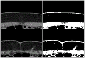
Fig. 4 shows the original image (in the left column) and the corresponding segmentation obtained using the threshold given by the Otsu method (in the right column).
Fig. 5 shows an outline of the image correction method.
Fig. 6 shows the module filling operation (left column) and the output of the original fascia segmentation (right column) of the example image used in fig. 4.
Figure 7 shows a preliminary fascia segmentation at the sagittal slice (left column) and corresponding final segment (right column).
Fig. 8 shows a graph representing the prediction obtained by the analysis of the local gradient and the corrective measure extraction step.
Fig. 9 shows a template for locating a ridge point.
FIG. 10 shows a center point correction, a) an initial cross-sectional image is superimposed with a gradient vector field; b) inner product response; c) and (4) estimating the center.
Figure 11 shows different slices of a patient's body (left column) and the corresponding costs obtained by applying the transformation to the Frangi (Frangi) vessel probabilities (right column) [16 ]. The arrows locate intramuscular blood vessels.
Fig. 12 shows a representation of the procedure in order to obtain a line along an axial cross section of a blood vessel. v | | | a is the projection of v on the a plane.
Fig. 13 shows the outline of the apparatus used.
Detailed Description
This document describes a method and apparatus for extracting relevant features of a perforator (vessel that penetrates an organ) and validation of a local gradient-based tracking procedure to detect the subcutaneous region of the perforator; validation of a-based search transformed frangy vessel segmentation [16] was used as a cost to extract the intramuscular route of the perforator.
The Champalimaud foundation of risbourne provides a Computed Tomography Angiography (CTA) volume from 20 different patients in digital imaging and communications in medicine (DICOM) format, and includes several axial slices, e.g., 50 or more, which are imaged perpendicular to the long axis of the patient's body, depending on the resolution required. CTA is a technique well known in the art for visualizing arteries and veins in a patient's body.
The CTA body can provide information from the entire abdominal region of the patient. The present document teaches a method that focuses on the anterior abdominal wall region, as there is a DIEP perforator present. Fig. 1 shows some examples of regions of interest, as well as tags of existing structures. Fig. 1a and 1c show CTA axial slices (not adjacent) with regions of interest in a white box. Fig. 1b and 1d show the corresponding regions of interest, wherein the important structures or regions are indicated: 1-right and left DIEA, 2-rectus abdominis, 3-subcutaneous region, 4-cutaneous tissue, 5-subcutaneous part of the perforator vessel, 6-intramuscular part of the perforator vessel.
In height, the body of interest starts with DIEA in the region of the posterior layer of the rectus sheath (see fig. 1b) and ends slightly above the navel. DIEA perforator vessels are not expected to be found on this section.
The process of perforating the branch vessels (subcutaneous and intramuscular) is provided by experts as a "Ground true" landmark-i.e. directly observed information. The Champalimaud fund provides one medical report for each patient. For example, a radiologist describes an existing perforator. The description includes the caliber (inner diameter) of the perforator, the location of the perforator away from the fascia, the subcutaneous route orientation and the intramuscular route curvature and length.
Fig. 2 illustrates a method according to an aspect of the invention. The first step 200 includes acquiring an image and then asking the radiologist to define a volume of interest, for example, by manually selecting the location of DIEA into the posterior layer of the rectus sheath and the end points of each perforator vessel (see fig. 3) at step 205. These represent landmarks used by the methods of the present disclosure to calculate the path of the blood vessel. It can be seen that in the perforator shown in figure 3 there are two endpoints 30a and 30b that form the first landmark and the location 32 where DIEA enters the posterior layer of the rectus sheath forms the second landmark. Fig. 3 shows a simplified diagram, as there are 6-8 perforator vessels in a female.
Followed by a method of automatically extracting the perforator with the help of these landmarks. In fig. 1d) it can be seen that the subcutaneous and intramuscular regions of the perforator exhibit distinct SNRs. This suggests a fast tracking method of obtaining the subcutaneous path in step 215 and a more complex least cost path method of extracting the intramuscular path in step 220.
To know how to separate these two regions, we first segment the anterior fascia of the muscle in step 210. Finally, after extracting the existing perforator, we generate a report containing the relevant features of each perforator at step 225.
The anterior fascia is a thin layer of tissue that separates the rectus abdominis muscle from the underlying soft tissue in the subcutaneous region. Based on the image intensity of CTA, it is believed that the anterior fascia cannot be easily distinguished from the rectus abdominis muscle. As mentioned above, the anterior fascia is considered to be the boundary between the rectus abdominus muscle and the subcutaneous region and is characterized by a transition from low intensity image pixels (indicating the subcutaneous region) to high intensity pixels (indicating the rectus abdominus muscle, i.e. the developed muscle region), which is present in all columns of each axial slice when only the region of interest is considered. Thus, the Otsu method [11] of reducing the grayscale image to a binary image was applied to the region of interest for each axial slice generated by CTA, with the purpose of distinguishing muscle from subcutaneous regions (see fig. 4 for an exemplary result). The original grayscale image is shown in the left column of fig. 4, and the corresponding segment (binary image) obtained using this threshold is given by Otsu method [11] and is shown in the right column of fig. 4.
This is followed by the method shown in figure 5 to obtain a preliminary segmentation of the fascia. At step 510, any skin detection of the image is removed. Skin is an artifact (artifact) on the image, which can be seen as a thin line on the image shown in fig. 4. The effect of the skin being removed can be seen in the picture on the left of figure 6. Skin is the area in the image that separates the soft tissue from the outside of the patient and is therefore not of interest. The test in step 520 determines whether a single component has extended to all columns. If not, then the threshold level of the binary image is changed in step 530 and any detected skin is removed in step 510 before repeating step 520.
Step 540 includes a fill operation to fill in the gaps that are apparent in the image due to component (component) missing (white pixels). On the left hand side of fig. 6 it can be seen that the filling operation has been completed.
As shown in the lower half of fig. 4, assume now that additional artifacts or objects are detected between the component and the skin in step 550. This object is called the "isthmus" and needs to be removed from the image in step 560. This may be done by removing pixels detected by calculating the horizontal derivative of the image intensity. Finally, step 570 is responsible for keeping the contours connected. Connected contour lines are considered lines in which each dark pixel of 8 neighbors or mole neighbors (Moore neighbor) is connected, that is, each other pixel is connected to an edge or corner of one pixel. It is assumed that some contours are found after processing the image, which is obviously not part of the boundary separating the muscle from the soft tissue of the subcutaneous region-this is an "orphan curve (orphancure)" but another unwanted artifact. These artifacts or curves then need to be removed from the image. An empirical decision is made that can delete missing curves as long as the connected orphan curve is less than n pixels, where n is empirically set to 11.
To achieve the final segmentation, which is a complete, more stationary version of the preliminary version, the new fascia estimation is set as the output of the local regression with preliminary detected neighbors on the sagittal plane. It is well known that in sagittal (sagittal) slices, the boundary between the muscle and subcutaneous regions is usually very smooth. New fascia points (p) for each line of each sagittal section of our body of interestrow,pcol) Given by the following equation:
pcol=P(prow) (1)
where P is a local regression model based on a bi-quadratic objective function, which takes into account the range [ P ]row-n,prow+n]Sagittal neighbors contained within, n is represented as:

s is the millimeter distance between successive pixels, the volume characteristics (the same in each volume direction after data interpolation), and m is the size of the largest structure to be ignored, also in millimeters. This is done to flatten the data in the image to eliminate the effect of the largest structures on the fascia segment. In this exemplary dataset, the vessel calibre is the largest structure that should be ignored. k is a constant. This last constant k is the amount of data that must be considered to remove the effects of structures (e.g., vessel calibre) from the image. In this task, m is considered to be 5, and k is empirically obtained to be 5. In other words, in order to remove or ignore structures that appear in three pixels of the image, it is necessary to use data from 3 times k pixels, i.e., from 15 neighboring pixels, for this calculation. The result of this method can be seen in fig. 7. It can be seen that the result of this equation is a smooth profile.
The detection of blood vessels will now be explained.
Assuming that the endpoint (first landmark) and fascia layer of each perforator vessel are known, a subcutaneous path may be calculated (step 210). The tracking procedure is used to estimate new centerline points along the vessel until reaching the fascia layer. The centerline points are calculated from the local vessel direction:

CPtis the centerline point estimated in iteration t, s is a scalar quantity that controls the steps given between successive centerline points (using s-1), and is a unit vector pointing in the direction of the local blood vessel. Based on Agam et al [12 ]]The latter being estimated by analysis of the local gradient vectorsUnit vector of
 Orientation of blood vessels
 Is the quantity that minimizes the squared projection of the local gradient vector to v:

where n is the number of local gradient vectors and giIs the ith gradient vector. The letter i denotes the index of the local gradient vector and goes from 1 to n. It will be appreciated that the number of local gradient vectors depends on the size of the window used. For example, if the window size is 3 x 3, then there will be 27 local gradient vectors that describe the neighbors of the voxel.
By means of representation

The former expression becomes e (v) ═ vTGGTv, wherein GGTIs a 3 x 3 correlation matrix. Such as Agam et al [12 ]]Shown, the minimum value of E (v) is determined by the GG belonging to its minimum feature valueTThe feature vector of (2) is obtained.
Then, in order to estimate CPt+1Using the value contained in CPtLocal gradient vectors in the neighborhood. The neighborhood is given by a p × p × p window, where p ═ 7 is empirically chosen for this task. Thus, in this example, the number of local gradient vectors is 7 × 7 × 7 ═ 343.
This method allows us to find the local orientation of the vessel through a p window. It can be seen that this method does not guarantee that the estimated centerline point is near the center of the vessel. To correct for this problem, we use an additional measurement method, which is incorporated into the framework by a Kalman filter [13 ]. It relies on the assumption that: voxels on the center of the vessel have a higher intensity, and as the distance from the center increases, the intensity of the voxels also decreases. In a two-dimensional image of the vessel cross-section, it is then expected that the central position Z can be found by analyzing the divergence of the gradient vector field.
Predicting new centerline points using local gradient vector information Then, the direction of the blood vessel containing the central line point is obtained
 Orthogonal planes (see fig. 8). It is expected that the plane will roughly comprise a circular, brighter region, which is a 2D cross-section of the vessel. The gradient vector field is calculated [14]And its similarity to the template represented in fig. 9 is evaluated by cross-correlation:

where f and g represent the gradient orientation vector field and the template vector field, respectively, and f is the complex conjugate of f. Center position estimate Zt+1Corresponding to the maximum response position (see fig. 10). Whenever corrective measures are available, the central point of the estimate is that the Kalman filter will be And corrective action Zt+1And outputting the fused information. In this task, we perform the corrective action once every 5 iterations. It is possible to calculate the corrective measures at least more frequently, but this will increase the computational cost.
We will now explain the calculation of the intramuscular route. As already said, images representing the intramuscular course of a perforator vessel generally have a very low SNR. Therefore, general tracking procedures are insufficient for the task of determining the intramuscular route. The use of a minimum cost approach has been proposed for finding an intramuscular vascular path between the site of transfixion to the fascia and the manually identified DIEA second landmark. As explained above, this is the location where the perforator crosses the posterior layer of the rectus sheath. The problem is therefore limited to finding a path connecting two voxels, resulting in a reduction of the required computational effort. Even so, using a simple Dijkstra search method to accomplish such a task may result in accessing a large number of voxels. The inventors propose to use the a-algorithm [15] because the a-algorithm includes a heuristic algorithm that improves search performance. In each iteration, the a-search algorithm expands the path that minimizes the following expression:
f(n)=g(n)+h(n) (7)
where n is the last node on the path, g (n) is the cost of the path from the start node to n, and h (n) is a heuristic that estimates the cost of the cheapest path from n to the target. In this task, the euclidean distance between n and the target voxel is used as a heuristic function.
In order to find the desired path, a lower cost of vessel voxels has to be given. The cost of travel from one node to another is given by the following expression:
cn,n+1=dn,n+1·C(n+1) (8)
where n is the current node, n +1 is the neighbor node, dn,n+1Is the euclidean distance between those nodes and C (n +1) is the terrain cost of the neighboring nodes. The adults are given by:

where F (n) is the Frangi vesselness segmentation [16] when voxel n is normalized to the range [0, 1 ]. This formula gives voxels a relatively high cost that does not fall within the vessel (f (n) ═ 0) and the cost in the range [1, 2], in order to guarantee that a heuristic algorithm can be employed.
The Fronqi method [16] for vessel segmentation computation aims at analyzing local intensity structures along the image and enhancing tubular objects in the image.
As is well known, the Hessian matrix is a square matrix of the second partial derivatives of the function. In the context of the Fronqi method [16], the function is the intensity distribution along a two-dimensional image or three-dimensional volume. Considering the three-dimensional volume, for each voxel, we compute the Hessian matrix H as follows:

where denotes the convolution operation, V is the local volume, G is a gaussian function, and its sigma determines the scale (scale) of the local structure being analyzed. The frenquency method is multi-ranging in that it calculates H on a different scale for each voxel.
For each of these matrices computed for each voxel, eigenvalue analysis is performed, obtaining three eigenvectors and their corresponding eigenvalues. The eigenvectors associated with the two eigenvalues with the highest absolute value point in the direction of higher local intensity curvature (but note that these eigenvectors point in the direction perpendicular to the vessel direction) and the last eigenvector points in the direction perpendicular to those two (in the vessel direction).
Then, for each voxel of our volume, one will have N pairs of eigenvalues, where N is the number of scales we have used. Each pair of three characteristic values lambda with increasing absolute values1,λ2,λ3. Franki vessel segmentation method [16]For each pair of calculations:

RA,RBs is obtained by correlation between characteristic values, e.g. Frensy [16]]As discussed. The basic idea is to produce a higher probability of blood vessel presence in tubular regions and a lower probability in blob-like and constant regions. Another constant is derived by the frenquency method and is present in the formula to control the sensitivity of each parameter. Grouping responses of different scales by selecting higher values of the Francis vessel segmentation method for each pixelAnd (6) mixing. This method then enables the enhancement of the vessel at different widths, due to the use of different dimensions. It will be appreciated that the lower scale enables detection of a vessel of narrower width.
Fig. 11 shows a slice belonging to one of the volumes from the database, and the corresponding cost obtained. The arrows point to the intramuscular vessels that should be enhanced so that the vessel path of interest can be correctly extracted. Our conclusion is that blood vessels are being distinguished, as well as some noisy regions. Even so, the cumulative path cost term will favor paths through the vessel, as they typically contain consecutive low-cost voxels.
The method enables the determination of the relevant characteristics of each perforator in a surgical plan in an objective and repeatable manner. Therefore, after extracting the blood vessels, we still need to replicate the medical report describing the following points.
At each tracking point of the subcutaneous region, we extract a line that passes through the tracking point of the subcutaneous region and cuts along a transverse plane of the perforator vessel in the axial plane (see fig. 12 for an illustration of the process). This line is used to derive the intensity profile of the cross-section in the de-noised version of the original image [17 ]. To measure the calibre, the gaussian is adapted to the profile in a least squares manner and with a width in millimeters covered by a confidence interval of 85%. Empirically, this value is considered to be the optimal value for the data contained in the database. The calibre of the last perforator is the average of the measures taken at each tracking point.
The perforator branches off the fascia site. This is considered to be where our tracking procedure has stopped due to reaching the fascia.
Orientation of the subcutaneous route. To know whether the perforator is oriented externally or centrally, and whether it is ascending or descending, we build a histogram of orientation vectors between successive centerline points and use a classifier that was previously trained using available annotation data.
The length and curvature of the intramuscular route. The length of the intramuscular path is given by the sum of the distances between successive points. To determine whether a path is short or long, a threshold learned with available annotation data is used. With respect to the tortuosity of a blood vessel, the inventors calculated a tortuosity metric [18] and used a classifier that outputs one of two classes, curved or linear. Again, the classifier is trained using the available annotation data.
FIG. 13 shows a non-limiting example of a system that may be used to implement the methods of this document. The system 100 includes a database 110 having a plurality of images 115 from axial slices of a patient. The database 110 is connected to a processor 120 on which software 130 is run to implement the method. A display device 140 is connected to the processor 120 and outputs the desired results.
Examples of the present invention
The anterior fascia layer was manually annotated for each body of the database of the champalacraft foundation. For each axial slice of the volume, several pixels of the anterior fascia are selected and linear interpolation is used to obtain the complete fascia segmentation. This Ground Truth annotation (Ground Truth annotation) is then compared to the segments obtained using the methods outlined herein. The average euclidean and hausdorff distances were calculated and the results are summarized in table 1.
Table 1. The results were obtained by the proposed fascial segmentation method. The average Euclidean and Housdov distances between the segment and the manual annotation, as well as the average execution time, are shown.


The spacing of the voxels varies between the volumes of the database, but in most cases it lies between 0.7 and 0.9 mm. This shows that the method proposed in the present disclosure is able to provide segments with an average distance from manual annotation that is lower than the distance between consecutive voxels. The MATLAB (R2014a) script was run using an Intel Core i7-4500U CPU 1.80@2.40GHz with an average run time of 636 seconds per individual.
In the whole database body, the expert annotated 74 subcutaneous and 28 intramuscular perforator routes. To initialize the vessel detection program of this document, tracking is started at ground truth landmarks near the end of the perforator vessel. After obtaining the two region paths, the Euclidean and Housdov distances from the ground truth annotation to the extracted path are computed because Euclidean distances are sparser than Housdov distances, and computing these metrics in another way produces a larger error than the true meaning. Table 2 summarizes the results obtained.
Table 2. Results obtained by using the proposed method to detect the subcutaneous and intramuscular regions of the perforator vessels.

Considering that the spacing between voxels is about 0.7-0.9mm, the method of the present disclosure extracts paths with an average error larger than a pixel. This error is believed to have two causes. First, the annotations provided by the radiologist are not in the form of bone, but the above results. This means that even if the retrieved path is a perfect skeleton of the vessel, the provided ground truth annotation can lead to significant errors when performing the comparison. The second reason, related only to the detection of the subcutaneous path, explains why the error is greater there, due to the fact that: gradient-based tracking algorithms are not suitable for correctly following a route around a muscle region (vessels and muscles appear to merge in intensity). Although it does not occur very often, it also accounts for increased errors. This also explains why the hausdorff distance reaches a relatively high value of 2.98 mm.
The estimate of calibre and the location of the perforator vessel out of the anterior fascia were also compared to ground truth. Note that to create a map of the perforator, only the width and height of the location where the perforator exits the fascia need to be considered. Thus, the error is evaluated independently for both. Table 3 summarizes the results obtained.
The aperture estimation method achieves an average error that corresponds to less than half the distance between consecutive voxels. It should be noted that the available caliber ground truth comes from reports made by different medical personnel, which increases the subjectivity of the procedure. Thus, if different experts annotate the same data, more conclusive results can be produced, so that variations between operators can be measured. Finally, for stopping the tracking procedure at the correct position, it can be noted that the error in the width offset is higher than in the height offset. This is because the already explained behaviour, i.e. the perforator vessels occasionally move along the muscle, often when crossing the axial plane. Then, stopping the tracking earlier, usually results in a higher offset of the width estimate than the height estimate, since the presence of muscle causes the local gradient vectors to be contaminated.
Table 3. The results obtained by using the proposed method to estimate the location and caliber of the perforator vessel exiting the fascia.

By using the method of the document, the characteristics of the DIEA perforator related to breast reconstruction surgery can be extracted. The method enables accurate segmentation of the fascia layer. This segmentation is used to separate the detection of a perforator into two separate problems: the subcutaneous route and the intramuscular route. Local gradient vector information is combined with the estimation of the center of a two-dimensional section blood vessel through a Kalman filtering method, and a subcutaneous route is correctly extracted so as to extract a new center line point in an iterative manner. An average error of 1.35mm is achieved. Intramuscular routes were extracted with an average error of 1.06mm using a frenqi vessel segmentation-based least cost path method.
After the step of detecting the blood vessel, each perforator can be characterized according to clinically relevant aspects. We achieved an average sub-voxel error when measuring calibre and determined the location of the perforator vessel out of the fascia, with an average error of about one half voxel. In addition, we propose an algorithm to obtain the orientation of the subcutaneous route of the perforator vessel and the length and curvature of its intramuscular area.
In view of the subcutaneous tracking procedure, attention should be paid to the perforator vessels that exhibit a clear path along the fascia. This makes the tracking method unstable in this region because the local gradient vector is destroyed and usually stops before it should stop, without retrieving the true coordinates of the region where the perforator vessel exits the fascia.
In terms of caliber estimation, different radiologists should provide respective ground truth to measure the variation between operators and compare with the results obtained by the developed framework. This is a very important point in view of the high subjectivity inherent in aperture estimation.
Finally, software has been developed that can render the detected blood vessels and display them with volume data.
Reference to the literature
Global cancer statistics, cancer clinicians, 65,5{29(2015)
Hewitt, M., Herdman, R., Holland, J.: Meeting the psychosocial needs of women with breast cancer (Meeting psychological aspects of women with breast cancer.) American academic Press (2004)
Lichter, A.A., Lippman, M.A., Danforth, D.A., Angelo, T.A., Steinberg, S.A., deMoss, E.A., Mac-Donald, H.A., Reichert, C.A., Merino, M.A., Swain, S.A., Cowan, K.A., Gerber, L.A., Bader, J.A., Findlay, P.A., Schain, W.A., Gorrell, C.A., Straus, K.A., Rosenberg, S.A., Glatstein, E.A. Mastectomy and breast protection therapy in the treatment of first and second stages of breast Cancer A random trial by the National Institute of Cancer research (Mastomy verbreast Cancer therapy of the tumor I and II) clinical trial of the tumor 359825. journal of Cancer research
McGuire, k., Santillan, a., Kaur, p., Meade, t., Parbhoo, j., Mathias, m., Shamehdi, c., Davis, m., Ramos, d., Cox, c.: does mastectomy increase? 13 Year Trend Analysis of Mastectomy and Breast protection treatment for 5865Patients (Are Mastecomies on the Rise
Increased mastectomy rates in early breast cancer in all age groups, one 10-year surgery selection study (incorporated breast cancer amplitude groups for early stage breast cancer) mammary journal, 18,318{325(2012) } 325
Mahmood, U.S., Hanlon, a., Koshy, m., Buras, r., Chumsri, s., tkanczuk, k.a., chemiton, s., region, w., Feigenberg, s.: Increasing the rate of breast cancer at the early stage of national mastectomy treatment (incorporated national mastectomy rates for the treatment of early stage cancer), year of surgical oncology 20,1436{43 2013 ]
Wexelman, B., Schwartz, J., Lee, D., Estabrook, A., Ma, A. (Socioeconomic and Geographdi _ organs in Immediate Reconstruction after Mastectomy) Socioeconomic and geographic factors of Immediate Reconstruction after Mastectomy. J. mammary gland 20,339{346(2014)
Cina, A., Salgarello, M., Barone-Adesi, L., Rinaldi, P., Bonomo, L., Breast reconstruction of deep inferior abdominal wall arteriopuncture vessels Multi-layer spiral CT angiography with Color Doppler contrast (Planning detailed description with deep introducer interventional instruments: Multi-detector CT imaging coverage Color Doppler US). radiology 255,979{987(2010)
Phillips, T., Stella, D., Rozen, W., Ashton, M., Taylor, G.: Abdominal wall CT angiography: a detailed description of a new preoperative imaging technique (Abdominal wall CT angiography: a characterized imaging count of a new anatomical imaging technique.) radiology 249,32{44(2008)
Overview of three-dimensional vessel lumen segmentation techniques-Models, features and extraction schemes (A review of 3D vessel lumen segmentation techniques: Models, features and extraction schemes) medical image analysis 13,819{845(2009) }
Otsu, N. threshold selection method for grayscale histograms (A threshold selection method from gray-level histograms), IEEE reports on systems, people and control theory 9,62{66(1979)
Agam, g., Armato, s., Wu, c.: vascular tree reconstruction applied to nodule detection in chest CT scans (Vessel tree recovery in clinical CT scans with application to node detection) report on IEEE medical imaging 24,486{499(2005)
A novel method of Linear Filtering and Prediction problem (A New Approach to Linear Filter and Prediction schemes) basic engineering journal 82,35{45(1960)
Oliveira, H., Cardoso, J., Magalhes, A., Cardoso, M. A3D low-cost solution for the aesthetic evaluation of breast cancer conservative treatment A computational method of biomechanical and biomedical engineering imaging and visualization 2,90{106(2014)
A formal basis for heuristic methods of determining minimum cost paths (A formal basis for the theoretical determination of minimum cost paths), IEEE systems, reports of science and control theory 4,100{107(1968)
Frangi, A., Niessen, W., Vincken, K., Vierger, M.: Multi-Scale enhancement Filtering medical Image Computing and Computer-Assisted Intervention (Multiscale vessel enhancement Filter Computing and Computer-Assisted interaction): Computer science classroom lecture 1496,130{137(1998)
DICTA 99 fifth International/national conference on digital image calculation, technology and applications 212{217(1999)
Bullitt, e., Gerig, G., Pizer, S., Lin, W., Aylward, S.: Measuring the degree of bending of the intracerebral vessels from MRA images IEEE trans-medical imaging 22,1163{1171(2003)
Claims (9)
1. A method for vessel segmentation, comprising:
acquiring (200) a plurality of images (115) having a plurality of voxels representing an axial slice through a region of interest;
defining (210) a fascia layer between a muscular region and a subcutaneous region by defining a boundary between a high intensity image and a low intensity image;
determining a first landmark and a second landmark of a blood vessel, wherein the first landmark is located on one side of the fascia layer and the second landmark is located on the other side of the fascia layer;
calculating (215) a subcutaneous path between the first landmark of the blood vessel and the fascia layer by an automatic tracking procedure comprising an analysis of a direction of a blood vessel along the blood vessel; and
calculating (220) an intramuscular path between the fascia layer and the second landmark by analyzing the voxels and automatically determining a least cost route given by the vessel segment of the voxels.
2. The method of claim 1, further comprising reducing a gray scale of the acquired plurality of images to form a binary image.
3. The method of any of the above claims, further comprising removing (510, 560) artifacts from the plurality of images.
4. The method of claim 3, wherein the artifacts in the image include pixels related to skin, other continuous feature voids.
5. The method of claim 1, wherein the analysis of the vessel direction is estimated by analysis of local gradient vectors.
6. The method of claim 1, wherein a center of the vessel is determined by intensity variations of voxels in the acquired plurality of images.
7. The method of claim 1, wherein the vessel segments of the voxels are determined according to the frangy method.
8. A device for vessel segmentation, comprising:
a database (110) for storing a plurality of images (115) of axial slices of a region of interest;
a processor (130) configured to analyze the plurality of images with software implementing the method according to one of claims 1-7; and
a display device (140) for outputting results from the software.
9. A computer readable medium having stored thereon instructions, which, when executed by a processor (130), cause the processor (130) to perform the method of any one of claims 1-7.
Applications Claiming Priority (2)
| Application Number | Priority Date | Filing Date | Title |
|---|---|---|---|
| PTPT109864 | 2017-01-19 | ||
| PT10986417 | 2017-01-19 |
Publications (2)
| Publication Number | Publication Date |
|---|---|
| CN108324300A CN108324300A (en) | 2018-07-27 |
| CN108324300B true CN108324300B (en) | 2020-12-22 |
Family
ID=60972077
Family Applications (1)
| Application Number | Title | Priority Date | Filing Date |
|---|---|---|---|
| CN201810055580.2A Expired - Fee Related CN108324300B (en) | 2017-01-19 | 2018-01-19 | Method and apparatus for vessel segmentation |
Country Status (5)
| Country | Link |
|---|---|
| US (1) | US20180199997A1 (en) |
| EP (1) | EP3352135B1 (en) |
| JP (1) | JP6776283B2 (en) |
| CN (1) | CN108324300B (en) |
| ES (1) | ES2757629T3 (en) |
Families Citing this family (9)
| Publication number | Priority date | Publication date | Assignee | Title |
|---|---|---|---|---|
| US10068340B2 (en) * | 2014-11-03 | 2018-09-04 | Algotec Systems Ltd. | Method for segmentation of the head-neck arteries, brain and skull in medical images |
| CN112384149A (en) * | 2018-07-13 | 2021-02-19 | 古野电气株式会社 | Ultrasonic imaging device, ultrasonic imaging system, ultrasonic imaging method, and ultrasonic imaging program |
| CN109903298B (en) * | 2019-03-12 | 2021-03-02 | 数坤(北京)网络科技有限公司 | Method, system and computer storage medium for repairing blood vessel segmentation image fracture |
| CN110547869B (en) * | 2019-09-17 | 2022-08-19 | 上海交通大学 | Preoperative auxiliary planning device based on virtual reality |
| CN112561884A (en) * | 2020-02-24 | 2021-03-26 | 广州柏视医疗科技有限公司 | Segmental naming system for pulmonary trachea and blood vessels |
| CN111612743B (en) * | 2020-04-24 | 2023-05-02 | 杭州电子科技大学 | CT image-based coronary artery central line extraction method |
| CN112545567B (en) * | 2021-02-22 | 2021-06-18 | 深圳华声医疗技术股份有限公司 | Ultrasonic image processing method and device, ultrasonic diagnostic equipment and storage medium |
| CN114202469B (en) * | 2021-11-11 | 2022-08-19 | 北京医准智能科技有限公司 | Method and device for selecting hyper-parameters of Frangi filter, electronic equipment and storage medium |
| CN115375705B (en) * | 2022-08-04 | 2023-03-31 | 北京医准智能科技有限公司 | Blood vessel segmentation method and device, electronic equipment and storage medium |
Citations (3)
| Publication number | Priority date | Publication date | Assignee | Title |
|---|---|---|---|---|
| US20070024617A1 (en) * | 2005-08-01 | 2007-02-01 | Ian Poole | Method for determining a path along a biological object with a lumen |
| CN103491874A (en) * | 2010-09-20 | 2014-01-01 | 诺瓦达克技术公司 | Locating and analyzing perforator flaps for plastic and reconstructive surgery |
| WO2015135985A1 (en) * | 2014-03-12 | 2015-09-17 | Stichting Katholieke Universiteit | Anatomical image projection system |
Family Cites Families (4)
| Publication number | Priority date | Publication date | Assignee | Title |
|---|---|---|---|---|
| US7783092B2 (en) * | 2006-01-17 | 2010-08-24 | Illinois Institute Of Technology | Method for enhancing diagnostic images using vessel reconstruction |
| US20070249912A1 (en) * | 2006-04-21 | 2007-10-25 | Siemens Corporate Research, Inc. | Method for artery-vein image separation in blood pool contrast agents |
| JP5566370B2 (en) | 2009-02-26 | 2014-08-06 | 株式会社日立メディコ | Medical image processing apparatus and method |
| GB2512585B (en) | 2013-04-01 | 2015-12-02 | Lumenis Ltd | Medical laser apparatus |
-
2018
- 2018-01-12 ES ES18151415T patent/ES2757629T3/en active Active
- 2018-01-12 EP EP18151415.9A patent/EP3352135B1/en active Active
- 2018-01-18 US US15/874,405 patent/US20180199997A1/en not_active Abandoned
- 2018-01-19 JP JP2018007127A patent/JP6776283B2/en active Active
- 2018-01-19 CN CN201810055580.2A patent/CN108324300B/en not_active Expired - Fee Related
Patent Citations (3)
| Publication number | Priority date | Publication date | Assignee | Title |
|---|---|---|---|---|
| US20070024617A1 (en) * | 2005-08-01 | 2007-02-01 | Ian Poole | Method for determining a path along a biological object with a lumen |
| CN103491874A (en) * | 2010-09-20 | 2014-01-01 | 诺瓦达克技术公司 | Locating and analyzing perforator flaps for plastic and reconstructive surgery |
| WO2015135985A1 (en) * | 2014-03-12 | 2015-09-17 | Stichting Katholieke Universiteit | Anatomical image projection system |
Non-Patent Citations (2)
| Title |
|---|
| Automating Perforator Flap MRA and CTA Reporting;Christopher J. Lange 等;《J Digit Imaging》;20170117;351-357 * |
| Comparative study of software techniques for 3D mapping of perforators in deep inferior epigastric artery perforator flap planning;Michael P.Chae 等;《Gland Surgery》;20160818;第5卷(第2期);99-106 * |
Also Published As
| Publication number | Publication date |
|---|---|
| JP2018134393A (en) | 2018-08-30 |
| EP3352135A1 (en) | 2018-07-25 |
| US20180199997A1 (en) | 2018-07-19 |
| JP6776283B2 (en) | 2020-10-28 |
| CN108324300A (en) | 2018-07-27 |
| EP3352135B1 (en) | 2019-09-11 |
| ES2757629T3 (en) | 2020-04-29 |
Similar Documents
| Publication | Publication Date | Title |
|---|---|---|
| CN108324300B (en) | Method and apparatus for vessel segmentation | |
| US10115039B2 (en) | Method and system for machine learning based classification of vascular branches | |
| JP6703082B2 (en) | Medical image processing apparatus for segmenting structures in medical image, method for segmenting medical image, and storage medium storing computer program for segmenting medical image | |
| JP6877868B2 (en) | Image processing equipment, image processing method and image processing program | |
| Bauer et al. | Segmentation of interwoven 3d tubular tree structures utilizing shape priors and graph cuts | |
| US10869644B2 (en) | Method and system for extracting lower limb vasculature | |
| CN104217418B (en) | The segmentation of calcification blood vessel | |
| EP2279490B1 (en) | Automatic detection and accurate segmentation of abdominal aortic aneurysm | |
| US10083515B2 (en) | Method and system for segmenting medical imaging data according to a skeletal atlas | |
| EP1851722B1 (en) | Image processing device and method | |
| Kuang et al. | Segmenting hemorrhagic and ischemic infarct simultaneously from follow-up non-contrast CT images in patients with acute ischemic stroke | |
| US8515133B2 (en) | Structure detection apparatus and method, and computer-readable medium storing program thereof | |
| CN111528871A (en) | Method and system for whole body bone removal and vessel visualization in medical images | |
| JP2017510406A (en) | Suppression of blood vessel structure in image | |
| Jimenez-Carretero et al. | Optimal multiresolution 3D level-set method for liver segmentation incorporating local curvature constraints | |
| Vukadinovic et al. | Segmentation of the outer vessel wall of the common carotid artery in CTA | |
| Alirr et al. | Survey on liver tumour resection planning system: steps, techniques, and parameters | |
| Tahoces et al. | Deep learning method for aortic root detection | |
| Cárdenes et al. | 3D modeling of coronary artery bifurcations from CTA and conventional coronary angiography | |
| Freiman et al. | Vessels-cut: a graph based approach to patient-specific carotid arteries modeling | |
| Zhao et al. | Automatic aortic dissection centerline extraction via morphology-guided CRN tracker | |
| Hemmati et al. | Segmentation of carotid arteries in computed tomography angiography images using fast marching and graph cut methods | |
| M'hiri et al. | Hierarchical segmentation and tracking of coronary arteries in 2D X-ray Angiography sequences | |
| Novikov et al. | Automated anatomy-based tracking of systemic arteries in arbitrary field-of-view CTA scans | |
| Araujo et al. | Computer aided detection of deep inferior epigastric perforators in computed tomography angiography scans |
Legal Events
| Date | Code | Title | Description |
|---|---|---|---|
| PB01 | Publication | ||
| PB01 | Publication | ||
| SE01 | Entry into force of request for substantive examination | ||
| SE01 | Entry into force of request for substantive examination | ||
| GR01 | Patent grant | ||
| GR01 | Patent grant | ||
| CF01 | Termination of patent right due to non-payment of annual fee |
Granted publication date: 20201222 Termination date: 20220119 |
|
| CF01 | Termination of patent right due to non-payment of annual fee |