CN108176820B - Fiber riser forming machine and working method thereof - Google Patents
Fiber riser forming machine and working method thereof Download PDFInfo
- Publication number
- CN108176820B CN108176820B CN201810133914.3A CN201810133914A CN108176820B CN 108176820 B CN108176820 B CN 108176820B CN 201810133914 A CN201810133914 A CN 201810133914A CN 108176820 B CN108176820 B CN 108176820B
- Authority
- CN
- China
- Prior art keywords
- lower die
- die
- riser
- moving mechanism
- cylinder
- Prior art date
- Legal status (The legal status is an assumption and is not a legal conclusion. Google has not performed a legal analysis and makes no representation as to the accuracy of the status listed.)
- Active
Links
Images


Classifications
-
- B—PERFORMING OPERATIONS; TRANSPORTING
- B22—CASTING; POWDER METALLURGY
- B22C—FOUNDRY MOULDING
- B22C9/00—Moulds or cores; Moulding processes
- B22C9/08—Features with respect to supply of molten metal, e.g. ingates, circular gates, skim gates
- B22C9/088—Feeder heads
Landscapes
- Engineering & Computer Science (AREA)
- Mechanical Engineering (AREA)
- Producing Shaped Articles From Materials (AREA)
- Moulds For Moulding Plastics Or The Like (AREA)
Abstract
The invention relates to a fiber riser forming machine which comprises a frame, a die, two groups of symmetrically arranged forming stations for producing risers and a feeding roller for conveying the risers, wherein the die comprises an upper die, a first lower die and a second lower die, and the forming stations comprise a first slurry tank, a second slurry tank, a vertical moving mechanism for driving the upper die to move, a transverse moving mechanism, a pressing mechanism, a rotating mechanism, a fixed ring, a picking mechanism for placing the fixed ring on the rotating mechanism and a receiving mechanism capable of vertically translating. The production process is fully automatic, layered riser heads can be produced, manual workpiece taking is not needed, labor force is greatly saved, and production cost is reduced.
Description
Technical Field
The invention belongs to the field of equipment for manufacturing casting risers, and particularly relates to a fiber riser forming machine and a working method thereof.
Background
The fiber riser is a riser product used in the casting industry, and the existing molding equipment used in the fiber riser is low in efficiency, and comprises the steps of immersing a die, vacuumizing, rotating and adsorbing a workpiece for preliminary molding, withdrawing a die belt workpiece, rolling a molding surface of the workpiece, moving the die belt workpiece to a cavity of a die, vibrating the die body to enable the workpiece to fall into a die cavity, placing a fixed ring, overturning the die, enabling the workpiece to fall together with the fixed ring to be in an operator, and conveying the operator to a drying production line. Because of the process is more, every process all needs personnel to go manual operation, and manual get the piece, degree of automation is low, and required human resource is big, and intensity of labour is higher, and the degree of difficulty is big especially when getting the piece, and then causes the finished piece precision low, and the rejection rate is high, and is with high costs, very extravagant raw materials.
Disclosure of Invention
In order to solve the problems, the invention provides a fiber riser forming machine and a working method thereof, wherein the forming machine can produce layered risers, can automatically discharge the risers without manually taking finished product risers, and achieves the full automation of the production process.
The technical scheme adopted by the invention is as follows:
the fiber riser forming machine comprises a frame, a die, two groups of symmetrically arranged forming stations for producing risers and a feeding roller for conveying the risers, wherein the die comprises an upper die, a first lower die and a second lower die, and the forming stations comprise a first slurry tank, a second slurry tank, a vertical moving mechanism for driving the upper die to move, a transverse moving mechanism, a material pressing mechanism, a rotating mechanism, a fixed ring, a picking mechanism for placing the fixed ring on the rotating mechanism and a material receiving mechanism capable of vertically translating;
the lower die support frames at the first slurry tank are used for supporting and fixing the first lower die, and the lower die support frames at the second slurry tank station are used for supporting and fixing the second lower die;
the transverse moving mechanism is provided with a moving frame for realizing transverse translation through a ball screw pair, and the vertical moving mechanism can vertically translate on the moving frame; a lower die locking cylinder used for being spliced and locked or separated with the lower die supporting frame and a rotating motor used for driving the upper die to axially rotate are fixed on the vertical moving mechanism;
the two groups of pressing mechanisms are respectively arranged corresponding to the first lower die and the second lower die; the pressing mechanism comprises a pressing cylinder, a rotating rod and a roller for rolling a riser, wherein one end of the rotating rod is connected with the extending end of the pressing cylinder, the roller is arranged at the other end of the rotating rod, and the middle part of the rotating rod is rotatably arranged on the lower die supporting frame; the length of the rotating rod and the extending length of the pressing cylinder can be selected according to the shape of the riser, and the expansion and contraction of the pressing cylinder can be controlled
The rotating mechanism comprises a temporary barrel for placing a finished riser and a rotating table horizontally arranged for clamping the temporary barrel, and the upper edge of the temporary barrel is fixed on the rotating table; the rotary table is provided with an air cylinder for locking or unlocking the fixed ring;
the picking mechanism comprises a transverse cylinder, a vertical cylinder and an electromagnet for adsorbing the fixing ring, wherein the electromagnet is fixed at the extending end of the vertical cylinder, and the vertical cylinder is fixed at the extending end of the transverse cylinder.
Above-mentioned fiber riser make-up machine, the shaping station still includes two sets of wiper mechanism that are used for wasing the mould that set up respectively in first thick liquid pond and No. two thick liquid ponds top.
Above-mentioned fiber riser make-up machine, still be provided with the agitator that is used for stirring the interior material of thick liquid pond in the frame.
According to the fiber riser forming machine, the first slurry tank and the second slurry tank are respectively provided with the liquid level sensing device.
The working method of the fiber riser forming machine comprises the following steps that two stations work simultaneously:
s1) starting a machine, running a stirrer, and supplementing slurry into a slurry tank through each feed inlet by external equipment;
s2) the upper die driven by the operation of the vertical moving mechanism descends to be matched with the first lower die, and the lower die locking cylinder pushes up to enable the lower die supporting frame to be locked with the vertical moving mechanism;
s3) the cleaning mechanism starts to clean the residual materials in the upper die and the first lower die;
s4) the vertical moving mechanism drives the lower die supporting frame to descend into the first slurry tank, the rotating motor operates, and the upper die and the first lower die after die assembly rotate together; closing the emptying valve and starting vacuumizing; ejecting a material pressing cylinder, and rolling a riser by a roller; stopping vacuumizing, and opening the emptying valve;
s5) the vertical moving mechanism drives the lower die supporting frame to ascend to the position above the first slurry tank and continuously rotate for a certain time;
s6) the material pressing mechanism retreats, the upper die and the first lower die stop rotating, and the adsorption molding of the first layer of material is completed;
s7) the lower die locking cylinder retreats to demould, the vertical moving mechanism drives the upper die to ascend so as to be completely separated from the lower die, and the first layer material is arranged in the upper die;
s8) the transverse moving mechanism drives the moving frame to transversely translate so that the vertical moving mechanism and the upper die move to the right to the second slurry tank together to start the second layer material adsorption molding, the upper die and the second lower die are matched, and the working steps are the same as those of the S3) to S7), so that a finished riser is manufactured;
s9) the transverse moving mechanism drives the moving frame to transversely translate so that the upper die with the finished product riser continuously moves right to the upper part of the rotating mechanism, the vertical moving mechanism descends to put the finished product riser into the temporary barrel, the cylinder of the vertical moving mechanism ejects out for unloading, and then the vertical moving mechanism returns to the station of the first slurry pool for the next round of process;
s10) a transverse cylinder of the picking mechanism moves to the right to enable the electromagnet to reach a picking station, a vertical cylinder descends, the electromagnet is electrified to attract the fixed ring, and then the picking mechanism places the fixed ring above the temporary bucket;
s11) the picking mechanism returns to the original station, and a cylinder on the rotary table is propped up to lock the fixed ring and the temporary bucket;
s12) turning over the rotating mechanism for 180 degrees to enable the finished riser to face downwards, enabling the receiving mechanism to ascend, and then enabling the air cylinder on the rotating table to retract to the fixed ring to be separated, wherein the finished riser is left on the receiving mechanism;
s13) the receiving mechanism is retracted to the original station, and the finished riser reaches the feeding roller for conveying; when the feeding roller is started, any receiving mechanism does not operate.
In the step S3), the cleaning time is 2 to 5 seconds.
The beneficial effects of the invention are as follows: the production process is fully automatic, layered riser heads can be produced, manual workpiece taking is not needed, labor force is greatly saved, and production cost is reduced. Two groups of risers can be produced simultaneously in one production period, and the production efficiency is greatly improved. Meanwhile, the device is provided with a flushing and cleaning mechanism, so that the influence of the residual materials on the precision of the die and the quality of the workpiece is reduced. The ball screw and the linear guide rail are connected, so that the influence of external factors such as vibration and the like generated in the running process of the equipment on the quality of a workpiece is greatly reduced.
Drawings
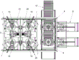
FIG. 1 is a schematic perspective view of the present invention;
FIG. 2 is a schematic front view of the present invention;
FIG. 3 is a schematic top view of the present invention;
FIG. 4 is a schematic illustration of the locking mechanism of the lower mold support frame and the vertical movement mechanism of the present invention;
FIG. 5 is a schematic diagram of the working principle of the pressing structure of the present invention;
fig. 6 is a schematic view of a pick-up mechanism of the present invention.
In the figure: the device comprises a frame 1, a first pulp pool 21, a second pulp pool 22, a feeding hole 23, a stirrer 3, a lower die supporting frame 4, a vertical moving mechanism 5, a lower die locking cylinder 51, a rotating motor 52, a transverse moving mechanism 6, a moving frame 61, a pressing mechanism 7, a pressing cylinder 71, a rotating rod 72, a roller 73, a rotating mechanism 8, a picking mechanism 9, a transverse cylinder 91, a vertical cylinder 92, an electromagnet 93, a cleaning mechanism 10, a receiving mechanism 11, a feeding roller 12, a fixed ring 13, a temporary barrel 14 and a finished product riser 15.
Detailed Description
The invention is further explained below with reference to the drawings.
In the illustration, in order to clearly express the technological processes of upper die forming, lower die forming, fixed ring compacting and material receiving, two vertical moving mechanisms 5 and fixed rings 13 under different technologies are shown on each station, and each station of the actual forming machine only has one vertical moving mechanism 5 and one fixed ring 13.
The fiber riser forming machine comprises a frame 1, a die, two groups of symmetrically arranged forming stations for producing risers and a feeding roller 12 for conveying the risers, wherein the die comprises an upper die, a first lower die and a second lower die, the forming stations comprise a first slurry tank 21, a second slurry tank 22, a vertical moving mechanism 5 for driving the upper die to move, a transverse moving mechanism 6, a material pressing mechanism 7, a rotating mechanism 8, a fixed ring 13, a picking mechanism 9 for placing the fixed ring 13 on the rotating mechanism 8 and a material receiving mechanism 11 capable of vertically translating;
the lower die supporting frames 4 and the pressing mechanisms 7 for compacting the shapes of riser blanks are arranged at the stations of the first pulp tank 21 and the second pulp tank 22, the lower die supporting frames 4 at the first pulp tank 21 are used for supporting and fixing the first lower die, and the lower die supporting frames 4 at the station of the second pulp tank 22 are used for supporting and fixing the second lower die;
the transverse moving mechanism 6 is provided with a moving frame 61 for realizing transverse translation through a ball screw pair, and the vertical moving mechanism 5 can vertically translate on the moving frame 61; a lower die locking cylinder 51 for being inserted into and locked with or separated from the lower die supporting frame 4 and a rotating motor 52 for driving the upper die to axially rotate are fixed on the vertical moving mechanism 5;
the two groups of pressing mechanisms 7 are respectively arranged corresponding to the first lower die and the second lower die; the pressing mechanism 7 comprises a pressing cylinder 71, a rotating rod 72 and a roller 73 for rolling a riser, one end of the rotating rod 72 is connected with the extending end of the pressing cylinder 71, the roller 73 is arranged at the other end of the rotating rod 72, and the middle part of the rotating rod 72 is rotatably arranged on the lower die supporting frame 4;
the rotating mechanism 8 comprises a temporary barrel 14 for placing a finished product riser 15 and a rotating table horizontally arranged for clamping the temporary barrel 14, wherein the upper edge of the temporary barrel 14 is fixed on the rotating table; the rotary table is provided with an air cylinder for locking or unlocking the fixed ring 13;
the picking mechanism 9 comprises a transverse cylinder 91, a vertical cylinder 92 and an electromagnet 93 for adsorbing the fixing ring 13, wherein the electromagnet 93 is fixed at the extending end of the vertical cylinder 92, and the vertical cylinder 92 is fixed at the extending end of the transverse cylinder 91.
The fiber riser forming machine further comprises two groups of cleaning mechanisms 10 which are respectively arranged above the first slurry tank 21 and the second slurry tank 22 and used for cleaning the die.
The fiber riser forming machine is characterized in that the frame 1 is also provided with a stirrer 3 for stirring materials in the slurry tank
In the fiber riser forming machine, the first slurry tank 21 and the second slurry tank 22 are respectively provided with a liquid level sensing device.
The working method of the fiber riser forming machine comprises the following steps that two stations work simultaneously:
s1) starting a machine, running a stirrer 3, and supplementing slurry into slurry tanks 21 and 22 through respective feed inlets 21 by external equipment;
s2) the upper die driven by the operation of the vertical moving mechanism 5 descends to be matched with the first lower die, and the lower die locking cylinder 51 is ejected out to enable the lower die supporting frame 4 to be locked with the vertical moving mechanism 5;
s3) the cleaning mechanism 10 starts to clean the residual materials in the upper die and the first lower die;
s4) the vertical moving mechanism 5 drives the lower die supporting frame 4 to descend into the first slurry tank 21, the rotating motor 52 operates, and the upper die and the first lower die after die assembly rotate together; closing the emptying valve and starting vacuumizing; the material pressing cylinder 71 is ejected, and the roller 73 rolls the riser to form; stopping vacuumizing, and opening the emptying valve;
s5) the vertical moving mechanism 5 drives the lower die supporting frame 4 to ascend to the position above the first slurry tank 21 and continuously rotate for a certain time;
s6) the material pressing mechanism 7 retreats, the upper die and the first lower die stop rotating, and the adsorption molding of the first layer of material is completed;
s7) the lower die locking cylinder 51 retreats to demould, the vertical moving mechanism 5 drives the upper die to ascend so as to be completely separated from the lower die, and the first layer material is arranged in the upper die;
s8) the transverse moving mechanism 6 drives the moving frame 61 to transversely translate so that the vertical moving mechanism 5 and the upper die move to the right to the second slurry tank 22 together to start the second layer material adsorption molding, the upper die and the second lower die are clamped, and the working steps are the same as those of the S3) to S7), so that a finished riser 15 is manufactured;
s9) the transverse moving mechanism 6 drives the moving frame 61 to transversely translate so that the upper die with the finished product riser 15 continues to move right above the rotating mechanism 8, the vertical moving mechanism 5 descends to put the finished product riser 15 into the temporary barrel 14, the cylinder of the vertical moving mechanism 5 ejects out for discharging, and then the vertical moving mechanism 5 returns to the station of the first slurry pool 21 for the next round of process;
s10) a transverse cylinder 91 of the picking mechanism 9 moves to the right to enable an electromagnet 93 to reach a picking station, a vertical cylinder 92 descends, the electromagnet 93 is electrified to suck the fixed ring 13, and then the picking mechanism 9 places the fixed ring 13 above the temporary bucket 14;
s11) the picking mechanism 9 returns to the original station, and simultaneously, a cylinder on the rotary table is ejected out to lock the fixed ring 13 and the temporary bucket 14;
s12) the rotating mechanism 8 turns 180 degrees to enable the finished product riser 15 to face downwards, the receiving mechanism 11 goes upwards, then the cylinder on the rotating table returns to the fixed ring 13 to be separated, and the finished product riser 15 is left on the receiving mechanism 11;
s13) the receiving mechanism 11 is retracted to the original station, and the finished product riser 15 reaches the feeding roller 12 for conveying; when the feed roller 12 is started, any one of the receiving mechanisms 11 does not operate.
In the step S3), the cleaning time is 2 to 5 seconds.
Claims (6)
1. A fiber riser forming machine is characterized in that: the feeder comprises a frame (1), a die, two groups of symmetrically arranged forming stations for producing the feeder and a feeding roller (12) for conveying the feeder, wherein the die comprises an upper die, a first lower die and a second lower die, the forming stations comprise a first pulp tank (21), a second pulp tank (22), a vertical moving mechanism (5) for driving the upper die to move, a transverse moving mechanism (6), a material pressing mechanism (7), a rotating mechanism (8), a fixed ring (13), a picking mechanism (9) for placing the fixed ring (13) on the rotating mechanism (8) and a material receiving mechanism (11) capable of vertically translating;
the lower die supporting frames (4) at the first pulp tank (21) and the second pulp tank (22) are respectively provided with a lower die supporting frame (4) and a pressing mechanism (7) for compacting the appearance of a riser blank, the lower die supporting frames (4) at the first pulp tank (21) are used for supporting and fixing the first lower die, and the lower die supporting frames (4) at the second pulp tank (22) station are used for supporting and fixing the second lower die;
the transverse moving mechanism (6) is provided with a moving frame (61) for realizing transverse translation through a ball screw pair, and the vertical moving mechanism (5) can vertically translate on the moving frame (61); a lower die locking cylinder (51) used for being spliced and locked or separated with the lower die supporting frame (4) and a rotating motor (52) used for driving the upper die to axially rotate are fixed on the vertical moving mechanism (5);
the two groups of pressing mechanisms (7) are respectively arranged corresponding to the first lower die and the second lower die; the pressing mechanism (7) comprises a pressing cylinder (71), a rotating rod (72) and a roller (73) for rolling a riser, one end of the rotating rod (72) is connected with the extending end of the pressing cylinder (71), the roller (73) is arranged at the other end of the rotating rod, and the middle part of the rotating rod (72) is rotatably arranged on the lower die supporting frame (4);
the rotating mechanism (8) comprises a temporary barrel (14) for placing a finished riser (15) and a rotating table horizontally arranged for clamping the temporary barrel (14), and the upper edge of the temporary barrel (14) is fixed on the rotating table; the rotary table is provided with an air cylinder for locking or unlocking the fixed ring (13);
the picking mechanism (9) comprises a transverse air cylinder (91), a vertical air cylinder (92) and an electromagnet (93) for adsorbing the fixing ring (13), wherein the electromagnet (93) is fixed at the extending end of the vertical air cylinder (92), and the vertical air cylinder (92) is fixed at the extending end of the transverse air cylinder (91).
2. The fiber riser forming machine of claim 1, wherein: the forming station also comprises two groups of cleaning mechanisms (10) which are respectively arranged above the first pulp tank (21) and the second pulp tank (22) and used for cleaning the die.
3. The fiber riser forming machine of claim 2 wherein: the machine frame (1) is also provided with a stirrer (3) for stirring materials in the slurry tank.
4. A fiber riser forming machine according to claim 3, wherein: liquid level sensing devices are respectively arranged in the first pulp tank (21) and the second pulp tank (22).
5. A method of operating a fiber feeder forming machine as claimed in claim 4, wherein the two stations operate simultaneously, comprising the steps of:
s1) starting a machine, running a stirrer (3), and supplementing slurry into slurry tanks (21, 22) through various feed inlets (21) by external equipment;
s2) an upper die driven by the vertical moving mechanism (5) to move downwards and a first lower die are matched, and a lower die locking cylinder (51) is ejected out to enable a lower die supporting frame (4) to be locked with the vertical moving mechanism (5);
s3) the cleaning mechanism (10) starts to clean the remnants in the upper die and the first lower die;
s4) the vertical moving mechanism (5) drives the lower die supporting frame (4) to descend into the first slurry tank (21), the rotating motor (52) operates, and the upper die and the first lower die after die assembly rotate together; closing the emptying valve and starting vacuumizing; the material pressing cylinder (71) is ejected, and the roller 73 rolls the riser to form; stopping vacuumizing, and opening the emptying valve;
s5) the vertical moving mechanism (5) drives the lower die supporting frame (4) to ascend to the position above the first slurry tank (21) and continuously rotate for a certain time;
s6) the material pressing mechanism (7) retreats, the upper die and the first lower die stop rotating, and the adsorption molding of the first layer of material is completed;
s7) a lower die locking cylinder (51) withdraws to demould, and a vertical moving mechanism (5) drives an upper die to move upwards so as to be completely separated from the lower die, wherein a first layer of material is arranged in the upper die;
s8) the transverse moving mechanism (6) drives the moving frame (61) to transversely translate so that the vertical moving mechanism (5) and the upper die move to the right to the second slurry tank (22) together to start the second layer material adsorption molding, the upper die and the second lower die are matched, the working steps are the same as those of the S3) to the S7), and a finished riser (15) is manufactured;
s9) the transverse moving mechanism (6) drives the moving frame (61) to transversely translate so that the upper die with the finished product riser (15) continues to move right to the position above the rotating mechanism (8), the vertical moving mechanism (5) descends to put the finished product riser (15) into the temporary barrel (14), a cylinder of the vertical moving mechanism (5) ejects out for discharging, and then the vertical moving mechanism (5) returns to a station of the first slurry pool (21) for the next round of process;
s10) a transverse air cylinder (91) of the picking mechanism (9) moves to the right to enable an electromagnet (93) to reach a picking station, a vertical air cylinder (92) descends, the electromagnet (93) is electrified to attract the fixed ring (13), and then the picking mechanism (9) places the fixed ring (13) above the temporary bucket (14);
s11) the picking mechanism (9) returns to the original station, and the cylinder on the rotary table pushes up to lock the fixed ring (13) and the temporary bucket (14);
s12) the rotating mechanism (8) turns 180 degrees to enable the finished product riser (15) to face downwards, the receiving mechanism (11) goes upwards, then a cylinder on the rotating table retreats to the fixed ring (13) to be separated, and the finished product riser (15) is left on the receiving mechanism (11);
s13) the receiving mechanism (11) is retracted to the original station, and the finished product riser (15) reaches the feeding roller (12) for conveying; when the feeding roller (12) is started, any receiving mechanism (11) does not operate.
6. The method of operation of claim 5, wherein: in the step S3), the cleaning time is 2 to 5 seconds.
Priority Applications (1)
| Application Number | Priority Date | Filing Date | Title |
|---|---|---|---|
| CN201810133914.3A CN108176820B (en) | 2018-02-09 | 2018-02-09 | Fiber riser forming machine and working method thereof |
Applications Claiming Priority (1)
| Application Number | Priority Date | Filing Date | Title |
|---|---|---|---|
| CN201810133914.3A CN108176820B (en) | 2018-02-09 | 2018-02-09 | Fiber riser forming machine and working method thereof |
Publications (2)
| Publication Number | Publication Date |
|---|---|
| CN108176820A CN108176820A (en) | 2018-06-19 |
| CN108176820B true CN108176820B (en) | 2023-04-28 |
Family
ID=62552562
Family Applications (1)
| Application Number | Title | Priority Date | Filing Date |
|---|---|---|---|
| CN201810133914.3A Active CN108176820B (en) | 2018-02-09 | 2018-02-09 | Fiber riser forming machine and working method thereof |
Country Status (1)
| Country | Link |
|---|---|
| CN (1) | CN108176820B (en) |
Citations (9)
| Publication number | Priority date | Publication date | Assignee | Title |
|---|---|---|---|---|
| JP2008264867A (en) * | 2007-03-29 | 2008-11-06 | Sintokogio Ltd | Foundry equipment for casting cast product |
| CN105014016A (en) * | 2015-08-02 | 2015-11-04 | 冯培永 | Full-automatic shrinkage suction filtration feed head forming equipment |
| CN105478684A (en) * | 2016-01-07 | 2016-04-13 | 济南标美精密机械有限公司 | Full-automatic core shooter |
| CN106881450A (en) * | 2017-04-21 | 2017-06-23 | 长兴鼎峰铸造材料有限公司 | A kind of rising head polishing labeling device |
| CN106890944A (en) * | 2017-04-14 | 2017-06-27 | 长兴鼎峰铸造材料有限公司 | A kind of rising head production equipment with automatic assembling and feeding function |
| CN106890943A (en) * | 2017-04-14 | 2017-06-27 | 长兴鼎峰铸造材料有限公司 | A kind of efficient production equipment of insulated feeder |
| CN106890942A (en) * | 2017-04-14 | 2017-06-27 | 长兴鼎峰铸造材料有限公司 | A kind of slideable upset shaping rising head equipment |
| CN106926357A (en) * | 2017-04-14 | 2017-07-07 | 长兴鼎峰铸造材料有限公司 | A kind of rising head automatic assembly line |
| CN207952534U (en) * | 2018-02-09 | 2018-10-12 | 济南标美精密机械有限公司 | A kind of fiber riser molding machine |
-
2018
- 2018-02-09 CN CN201810133914.3A patent/CN108176820B/en active Active
Patent Citations (9)
| Publication number | Priority date | Publication date | Assignee | Title |
|---|---|---|---|---|
| JP2008264867A (en) * | 2007-03-29 | 2008-11-06 | Sintokogio Ltd | Foundry equipment for casting cast product |
| CN105014016A (en) * | 2015-08-02 | 2015-11-04 | 冯培永 | Full-automatic shrinkage suction filtration feed head forming equipment |
| CN105478684A (en) * | 2016-01-07 | 2016-04-13 | 济南标美精密机械有限公司 | Full-automatic core shooter |
| CN106890944A (en) * | 2017-04-14 | 2017-06-27 | 长兴鼎峰铸造材料有限公司 | A kind of rising head production equipment with automatic assembling and feeding function |
| CN106890943A (en) * | 2017-04-14 | 2017-06-27 | 长兴鼎峰铸造材料有限公司 | A kind of efficient production equipment of insulated feeder |
| CN106890942A (en) * | 2017-04-14 | 2017-06-27 | 长兴鼎峰铸造材料有限公司 | A kind of slideable upset shaping rising head equipment |
| CN106926357A (en) * | 2017-04-14 | 2017-07-07 | 长兴鼎峰铸造材料有限公司 | A kind of rising head automatic assembly line |
| CN106881450A (en) * | 2017-04-21 | 2017-06-23 | 长兴鼎峰铸造材料有限公司 | A kind of rising head polishing labeling device |
| CN207952534U (en) * | 2018-02-09 | 2018-10-12 | 济南标美精密机械有限公司 | A kind of fiber riser molding machine |
Also Published As
| Publication number | Publication date |
|---|---|
| CN108176820A (en) | 2018-06-19 |
Similar Documents
| Publication | Publication Date | Title |
|---|---|---|
| CN210880133U (en) | Rotary type step-by-step positioning full-automatic brick press | |
| CN106041770A (en) | Full-automatic rotary multi-station grinding wheel forming machine | |
| CN111054561A (en) | Paint spraying apparatus is used in mould processing | |
| CN110510377B (en) | Automatic overturning demolding packaging equipment | |
| CN108252164B (en) | Automatic forming machine for double-time down-suction slurry of molded product and manufacturing method | |
| CN210633847U (en) | Rotary station type core mould vibration pipe making machine | |
| CN109878137B (en) | Continuous feeding press | |
| CN108176820B (en) | Fiber riser forming machine and working method thereof | |
| KR101951899B1 (en) | A ice cup molding apparatus | |
| CN211221198U (en) | Ceramic roll forming production line | |
| CN207952534U (en) | A kind of fiber riser molding machine | |
| CN113600788B (en) | Die-casting mechanical demolding and separating equipment for manufacturing precise structural part and implementation method | |
| CN213082233U (en) | Horizontal injection machine | |
| CN213891109U (en) | Automatic change out die clamper | |
| CN213674720U (en) | Ceramic roller press | |
| CN114161280A (en) | Novel moulding of micro motor magnetic ring magnetic shoe device | |
| CN110654052B (en) | Mold device for producing horn basin body and production method using mold device | |
| CN220897845U (en) | Tea cake pressing device | |
| CN113977884B (en) | Automatic rotary thread demolding machine | |
| CN213675214U (en) | Injection mold of automotive interior spare | |
| US3751206A (en) | Machines for use in the manufacture of pottery ware | |
| CN211413532U (en) | Precision die forging processing equipment | |
| CN117637336B (en) | Soft magnetic ferrite magnetic core element compression molding equipment and method thereof | |
| CN215455028U (en) | Moon cake forming device | |
| CN218876407U (en) | Mold base |
Legal Events
| Date | Code | Title | Description |
|---|---|---|---|
| PB01 | Publication | ||
| PB01 | Publication | ||
| SE01 | Entry into force of request for substantive examination | ||
| SE01 | Entry into force of request for substantive examination | ||
| GR01 | Patent grant | ||
| GR01 | Patent grant |