CN108174224B - Video encoding method and apparatus, and video decoding method and apparatus - Google Patents
Video encoding method and apparatus, and video decoding method and apparatus Download PDFInfo
- Publication number
- CN108174224B CN108174224B CN201810251649.9A CN201810251649A CN108174224B CN 108174224 B CN108174224 B CN 108174224B CN 201810251649 A CN201810251649 A CN 201810251649A CN 108174224 B CN108174224 B CN 108174224B
- Authority
- CN
- China
- Prior art keywords
- picture
- temporal
- layer access
- temporal layer
- access picture
- Prior art date
- Legal status (The legal status is an assumption and is not a legal conclusion. Google has not performed a legal analysis and makes no representation as to the accuracy of the status listed.)
- Active
Links
Images


Classifications
-
- H—ELECTRICITY
- H04—ELECTRIC COMMUNICATION TECHNIQUE
- H04N—PICTORIAL COMMUNICATION, e.g. TELEVISION
- H04N9/00—Details of colour television systems
- H04N9/12—Picture reproducers
- H04N9/31—Projection devices for colour picture display, e.g. using electronic spatial light modulators [ESLM]
-
- H—ELECTRICITY
- H04—ELECTRIC COMMUNICATION TECHNIQUE
- H04N—PICTORIAL COMMUNICATION, e.g. TELEVISION
- H04N19/00—Methods or arrangements for coding, decoding, compressing or decompressing digital video signals
- H04N19/30—Methods or arrangements for coding, decoding, compressing or decompressing digital video signals using hierarchical techniques, e.g. scalability
- H04N19/31—Methods or arrangements for coding, decoding, compressing or decompressing digital video signals using hierarchical techniques, e.g. scalability in the temporal domain
-
- H—ELECTRICITY
- H04—ELECTRIC COMMUNICATION TECHNIQUE
- H04N—PICTORIAL COMMUNICATION, e.g. TELEVISION
- H04N19/00—Methods or arrangements for coding, decoding, compressing or decompressing digital video signals
- H04N19/30—Methods or arrangements for coding, decoding, compressing or decompressing digital video signals using hierarchical techniques, e.g. scalability
-
- H—ELECTRICITY
- H04—ELECTRIC COMMUNICATION TECHNIQUE
- H04N—PICTORIAL COMMUNICATION, e.g. TELEVISION
- H04N19/00—Methods or arrangements for coding, decoding, compressing or decompressing digital video signals
- H04N19/10—Methods or arrangements for coding, decoding, compressing or decompressing digital video signals using adaptive coding
- H04N19/102—Methods or arrangements for coding, decoding, compressing or decompressing digital video signals using adaptive coding characterised by the element, parameter or selection affected or controlled by the adaptive coding
- H04N19/119—Adaptive subdivision aspects, e.g. subdivision of a picture into rectangular or non-rectangular coding blocks
-
- H—ELECTRICITY
- H04—ELECTRIC COMMUNICATION TECHNIQUE
- H04N—PICTORIAL COMMUNICATION, e.g. TELEVISION
- H04N19/00—Methods or arrangements for coding, decoding, compressing or decompressing digital video signals
- H04N19/10—Methods or arrangements for coding, decoding, compressing or decompressing digital video signals using adaptive coding
- H04N19/169—Methods or arrangements for coding, decoding, compressing or decompressing digital video signals using adaptive coding characterised by the coding unit, i.e. the structural portion or semantic portion of the video signal being the object or the subject of the adaptive coding
- H04N19/17—Methods or arrangements for coding, decoding, compressing or decompressing digital video signals using adaptive coding characterised by the coding unit, i.e. the structural portion or semantic portion of the video signal being the object or the subject of the adaptive coding the unit being an image region, e.g. an object
- H04N19/172—Methods or arrangements for coding, decoding, compressing or decompressing digital video signals using adaptive coding characterised by the coding unit, i.e. the structural portion or semantic portion of the video signal being the object or the subject of the adaptive coding the unit being an image region, e.g. an object the region being a picture, frame or field
-
- H—ELECTRICITY
- H04—ELECTRIC COMMUNICATION TECHNIQUE
- H04N—PICTORIAL COMMUNICATION, e.g. TELEVISION
- H04N19/00—Methods or arrangements for coding, decoding, compressing or decompressing digital video signals
- H04N19/46—Embedding additional information in the video signal during the compression process
-
- H—ELECTRICITY
- H04—ELECTRIC COMMUNICATION TECHNIQUE
- H04N—PICTORIAL COMMUNICATION, e.g. TELEVISION
- H04N19/00—Methods or arrangements for coding, decoding, compressing or decompressing digital video signals
- H04N19/50—Methods or arrangements for coding, decoding, compressing or decompressing digital video signals using predictive coding
- H04N19/503—Methods or arrangements for coding, decoding, compressing or decompressing digital video signals using predictive coding involving temporal prediction
- H04N19/51—Motion estimation or motion compensation
- H04N19/513—Processing of motion vectors
- H04N19/517—Processing of motion vectors by encoding
- H04N19/52—Processing of motion vectors by encoding by predictive encoding
-
- H—ELECTRICITY
- H04—ELECTRIC COMMUNICATION TECHNIQUE
- H04N—PICTORIAL COMMUNICATION, e.g. TELEVISION
- H04N19/00—Methods or arrangements for coding, decoding, compressing or decompressing digital video signals
- H04N19/70—Methods or arrangements for coding, decoding, compressing or decompressing digital video signals characterised by syntax aspects related to video coding, e.g. related to compression standards
Abstract
Provided are a video encoding method and apparatus and a video decoding method and apparatus. The video encoding method includes: dividing a picture included in a picture sequence into temporal sub-layers; classifying a temporal layer access picture as a first temporal layer access picture or a second temporal layer access picture based on whether a picture that is encoded after the temporal layer access picture and belongs to the same temporal sub-layer as the temporal layer access picture or belongs to a temporal sub-layer higher than the temporal layer access picture can refer to a picture that is encoded before the temporal layer access picture; type syntax information for identifying the first temporal layer access picture and the second temporal layer access picture is added to transmission unit data including the temporal layer access pictures.
Description
The present application is a divisional application No. 201380045893.5 entitled "method and apparatus for encoding video with temporal scalability and method and apparatus for decoding video with temporal scalability", filed on 2013, month 07, 03 with the filing date to the office of intellectual property.
Technical Field
The present invention relates to encoding and decoding video, and more particularly, to a video encoding and decoding method and apparatus having temporal scalability.
Background
Video codecs such as ITU-T H.261, ISO/IEC MPEG-1 Vision, IUT-T H.262(ISO/IEC MPEG-2 Vision), ITU-T H.264, ISO/IEC MPEG-4 Vision, and ITU-T H.264(ISO/IEC MPEG-4 AVC) perform predictive coding on macroblocks via inter prediction or intra prediction, and generate and output bitstreams according to predetermined formats defined by each video codec by using the coded image data.
According to the related art, video with temporal scalability is provided by applying a hierarchical B picture or Motion Compensated Temporal Filtering (MCTF).
Disclosure of Invention
Technical problem
Since a picture encoded after a temporal layer access picture accessed during temporal layer switching can use a picture encoded before the temporal layer access picture as a reference picture, video compression efficiency can be improved.
Further, transport unit data of a temporal layer access picture and transport unit data of a picture that cannot be decoded during temporal layer switching can be distinguished from each other in a Network Adaptation Layer (NAL) unit.
Solution scheme
According to an embodiment of the present invention, a temporal layer access picture is classified by distinguishing when and when pictures that can be referred to by pictures decoded after the temporal layer access picture are limited, and information for identifying the classified temporal layer access picture is added to a transmission data unit.
Advantageous effects
According to one or more embodiments of the present invention, it is possible to skip unnecessary processes of decoding a picture and save hardware resources by identifying and discarding Network Adaptation Layer (NAL) units with respect to pictures that cannot be decoded after a temporal layer access picture. Further, according to one or more embodiments of the present invention, since a picture encoded after a temporal layer access picture can use a picture encoded before the temporal layer access picture as a reference picture, video compression efficiency can be improved.
Drawings
Fig. 1 is a block diagram of a video encoding apparatus according to an embodiment of the present invention.
Fig. 2 is a block diagram of a video decoding apparatus according to an embodiment of the present invention.
Fig. 3 is a diagram illustrating the concept of a coding unit according to an embodiment of the present invention.
Fig. 4 is a block diagram of an image encoder based on an encoding unit according to an embodiment of the present invention.
Fig. 5 is a block diagram of an image decoder based on a coding unit according to an embodiment of the present invention.
Fig. 6 is a diagram illustrating a deeper coding unit according to depth and a partition according to an embodiment of the present invention.
Fig. 7 is a diagram illustrating a relationship between a coding unit and a transform unit according to an embodiment of the present invention.
Fig. 8 is a diagram illustrating encoding information of a coding unit corresponding to a coded depth according to an embodiment of the present invention.
Fig. 9 is a diagram of a deeper coding unit according to depth according to an embodiment of the present invention.
Fig. 10, 11 and 12 are diagrams illustrating a relationship between a coding unit, a prediction unit and a frequency transform unit according to an embodiment of the present invention.
Fig. 13 is a diagram illustrating a relationship among a coding unit, a prediction unit, and a transform unit according to the coding mode information of table 1.
Fig. 14 is a diagram of a video encoding apparatus having temporal scalability according to an embodiment of the present invention.
Fig. 15 is a diagram of pictures divided into temporal sub-layers included in a picture sequence according to an embodiment of the present invention.
Fig. 16 is a diagram of a screen displayed according to a frame rate according to an embodiment of the present invention.
Fig. 17 is a diagram for describing a leading picture and a first time layer visit according to an embodiment of the present invention.
Fig. 18 is a diagram for describing a leading picture that cannot be decoded during temporal layer up-switching according to an embodiment of the present invention.
Fig. 19 is a diagram of a Network Adaptation Layer (NAL) unit according to an embodiment of the present invention.
Fig. 20 is a flowchart illustrating a video encoding method with temporal scalability according to an embodiment of the present invention.
Fig. 21 is a diagram of a video decoding apparatus having temporal scalability according to an embodiment of the present invention.
Fig. 22 is a flowchart illustrating a video decoding method with temporal scalability according to an embodiment of the present invention.
Best mode for carrying out the invention
According to an aspect of the present invention, there is provided a video encoding method having temporal scalability, the video encoding method including: dividing a picture included in a picture sequence into temporal sub-layers; classifying a temporal layer access picture as a first temporal layer access picture or a second temporal layer access picture based on whether a picture that is encoded after the temporal layer access picture and belongs to the same temporal sub-layer as the temporal layer access picture or belongs to a temporal sub-layer higher than the temporal layer access picture can refer to a picture that is encoded before the temporal layer access picture; type syntax information for identifying the first temporal layer access picture and the second temporal layer access picture is added to transmission unit data including the temporal layer access pictures.
According to another aspect of the present invention, there is provided a video encoding apparatus having temporal scalability, the video encoding apparatus including: a video encoder dividing a picture included in a picture sequence into temporal sub-layers; a multiplexer classifying the temporal layer access picture as a first temporal layer access picture or a second temporal layer access picture based on whether a picture that is encoded after the temporal layer access picture and belongs to the same temporal sublayer as the temporal layer access picture or belongs to a temporal sublayer higher than the temporal layer access picture can refer to a picture that is encoded before the temporal layer access picture, and adding type syntax information for identifying the first temporal layer access picture and the second temporal layer access picture to transmission unit data including the temporal layer access picture.
According to another aspect of the present invention, there is provided a video decoding method having temporal scalability, the video decoding method including: receiving transmission unit data obtained by dividing and encoding pictures included in a picture sequence into temporal sub-layers; identifying transmission unit data by using type syntax information included in the transmission unit data: the transport unit data includes a temporal layer access picture accessed to perform temporal layer up-switching from a lower temporal sublayer to a higher temporal sublayer, wherein the temporal layer access picture is classified as a first temporal layer access picture or a second temporal layer access picture based on whether a picture decoded after the temporal layer access picture and belonging to the same temporal sublayer as the temporal layer access picture or to a temporal sublayer higher than the temporal layer access picture can refer to a picture decoded before the temporal layer access picture.
According to another aspect of the present invention, there is provided a video decoding apparatus having temporal scalability, the video decoding apparatus including: a receiver receiving transmission unit data obtained by dividing and encoding pictures included in a picture sequence into temporal sub-layers; an inverse multiplexer for identifying the transmission unit data by using the type syntax information included in the transmission unit data: the transport unit data includes a temporal layer access picture accessed to perform temporal layer up-switching from a lower temporal sublayer to a higher temporal sublayer, wherein the temporal layer access picture is classified as a first temporal layer access picture or a second temporal layer access picture based on whether a picture decoded after the temporal layer access picture and belonging to the same temporal sublayer as the temporal layer access picture or to a temporal sublayer higher than the temporal layer access picture can refer to a picture decoded before the temporal layer access picture.
Detailed Description
One or more embodiments of the present invention will be described more fully hereinafter with reference to the accompanying drawings. While one or more embodiments of the present invention are described, an image may include a still image or a moving image, and may also be referred to as a video. Further, while one or more embodiments of the present invention are described, the image frames may also be referred to as pictures.
Fig. 1 is a block diagram of a video encoding apparatus according to an embodiment of the present invention.
The video encoding apparatus 100 according to the embodiment includes a maximum coding unit divider 110, a coding unit determiner 120, and an output unit 130.
The maximum coding unit divider 110 may divide the current picture based on a maximum coding unit of the current picture of the image, wherein the maximum coding unit is a coding unit having a maximum size. If the current picture is greater than the maximum coding unit, the image data of the current picture may be divided into at least one maximum coding unit. The maximum coding unit according to the embodiment may be a data unit having a size of 32 × 32, 64 × 64, 128 × 128, or 256 × 256, wherein the shape of the data unit is a square having a width and a length of several powers of 2. The image data may be output to the coding unit determiner 120 according to at least one maximum coding unit.
A coding unit according to an embodiment may be characterized by a maximum size and depth. The depth represents the number of times a coding unit is spatially divided from a maximum coding unit, and as the depth deepens, deeper coding units according to the depth may be divided from the maximum coding unit to a minimum coding unit. The depth of the maximum coding unit is the highest depth, and the depth of the minimum coding unit is the lowest depth. Since the size of the coding unit corresponding to each depth is reduced as the depth of the maximum coding unit is deepened, the coding unit corresponding to the higher depth may include a plurality of coding units corresponding to the lower depths.
As described above, the image data of the current picture is divided into maximum coding units according to the maximum size of the coding units, and each maximum coding unit may include deeper coding units divided according to depths. Since the maximum coding unit according to the embodiment is divided according to the depth, image data of a spatial domain included in the maximum coding unit may be hierarchically classified according to the depth.
A maximum depth and a maximum size of the coding unit may be previously set, wherein the maximum depth and the maximum size limit the total number of times the height and width of the maximum coding unit are hierarchically divided.
The coding unit determiner 120 encodes at least one split region obtained by splitting a region of a maximum coding unit according to depths, and determines a depth for outputting a final coding result according to the at least one split region. In other words, the coding unit determiner 120 determines the coded depth by encoding image data in deeper coding units according to depths according to the maximum coding unit of the current picture, and selecting a depth having the smallest coding error. The determined coded depth and the image data according to the maximum coding unit are output to the output unit 130.
The image data in the maximum coding unit is encoded based on deeper coding units corresponding to at least one depth equal to or lower than the maximum depth, and the encoding results are compared based on each of the deeper coding units. After comparing the coding errors of the deeper coding units, the depth having the smallest coding error may be selected. At least one coded depth may be selected for each maximum coding unit.
As the coding units are hierarchically divided according to depths, the size of the maximum coding unit is divided, and the number of coding units increases. In addition, even if the coding units correspond to the same depth in one maximum coding unit, whether to divide each coding unit corresponding to the same depth into lower depths is determined by measuring coding errors of data of each coding unit, respectively. Accordingly, even if data is included in one maximum coding unit, a coding error according to a depth is different according to a region, and thus a coded depth may be different according to a region. Accordingly, one or more coded depths may be determined for one maximum coding unit, and data of the maximum coding unit may be divided according to coding units of the one or more coded depths.
Accordingly, the coding unit determiner 120 according to an embodiment may determine coding units having a tree structure included in the current maximum coding unit. The "coding units having a tree structure" according to an embodiment of the present invention includes coding units corresponding to depths determined as coded depths among all deeper coding units included in a maximum coding unit. The coding units of coded depths may be hierarchically determined according to depths in the same region of the maximum coding unit, and the coding units of coded depths may be independently determined in different regions. Similarly, the coded depth in a current region may be determined independently of the coded depth of another region.
The maximum depth according to the embodiment is an index related to the number of times division is performed from the maximum coding unit to the minimum coding unit. The first maximum depth according to an embodiment may represent a total number of times division is performed from a maximum coding unit to a minimum coding unit. The second maximum depth according to the embodiment may represent a total number of depth levels from the maximum coding unit to the minimum coding unit. For example, when the depth of the maximum coding unit is 0, the depth of a coding unit divided once for the maximum coding unit may be set to 1, and the depth of a coding unit divided twice for the maximum coding unit may be set to 2. In this case, if the minimum coding unit is a coding unit obtained by dividing the maximum coding unit four times, there are 5 depth levels of depths 0, 1, 2, 3, and 4, and thus the first maximum depth may be set to 4 and the second maximum depth may be set to 5.
The predictive coding and the frequency transform may be performed according to a maximum coding unit. Also according to the maximum coding unit, prediction coding and transformation are performed based on a deeper coding unit according to a depth equal to or less than the maximum depth.
Since the number of deeper coding units increases every time the maximum coding unit is divided according to the depth, encoding including prediction encoding and frequency transform will have to be performed on all the deeper coding units generated as the depth deepens. For convenience of explanation, among the at least one maximum coding unit, prediction coding and frequency transformation will now be described based on a coding unit of a current depth.
The video encoding apparatus 100 according to the embodiment may variously select the size or shape of a data unit for encoding image data. In order to encode image data, operations such as predictive encoding, frequency transform, and entropy encoding are performed, and at this time, the same data unit may be used for all operations, or a different data unit may be used for each operation.
For example, the video encoding apparatus 100 may select not only a coding unit for encoding image data but also a data unit different from the coding unit so as to perform predictive encoding on the image data in the coding unit.
In order to perform prediction encoding in the maximum coding unit, prediction encoding may be performed based on a coding unit corresponding to a coded depth (i.e., based on a coding unit that is no longer divided into coding units corresponding to lower depths). Hereinafter, a coding unit that is not divided any more and becomes a basic unit for prediction coding will now be referred to as a "prediction unit". The partition obtained by dividing the prediction unit may include the prediction unit and a data unit obtained by dividing at least one of a height and a width of the prediction unit.
For example, when a coding unit of 2N × 2N (where N is a positive integer) is no longer divided, the coding unit becomes a prediction unit of 2N × 2N, and the size of the partition may be 2N × 2N, 2N × N, N × 2N, or N × N. Examples of the partition type include a symmetric partition obtained by symmetrically dividing the height or width of the prediction unit, a partition obtained by asymmetrically dividing the height or width of the prediction unit (such as 1: n or n:1), a partition obtained by geometrically dividing the prediction unit, and a partition having an arbitrary shape.
The prediction mode of the prediction unit may be at least one of an intra mode, an inter mode, and a skip mode. For example, the intra mode or the inter mode may be performed on a partition of 2N × 2N, 2N × N, N × 2N, or N × N. In addition, the skip mode may be performed only for the partition of 2N × 2N. Encoding may be independently performed on one prediction unit in the encoding unit, thereby selecting a prediction mode having a minimum encoding error.
The video encoding apparatus 100 according to the embodiment may perform frequency transformation on image data in a coding unit based not only on a coding unit for encoding the image data but also on a data unit different from the coding unit.
In order to perform frequency transformation in the coding unit, the frequency transformation may be performed based on a data unit having a size less than or equal to the coding unit. For example, the data unit for frequency transform may include a data unit of an intra mode and a data unit of an inter mode.
The data unit used as the basis for the frequency transformation will now be referred to as "transformation unit". Similar to the coding unit, the transform unit in the coding unit may be recursively divided into transform units of smaller sizes, and thus the residual data in the coding unit may be divided based on the transform units having a tree structure according to the transform depth.
A transform depth indicating the number of times of division performed by the transform unit by dividing the height and width of the coding unit may also be set in the transform unit according to the embodiment. For example, in a current coding unit of 2N × 2N, the transform depth may be 0 when the size of the transform unit is 2N × 2N, 1 when the size of the transform unit is N × N, and 2 when the size of the transform unit is N/2 × N/2. That is, the transform unit having a tree structure may also be set according to the transform depth.
The encoding information according to the coding unit corresponding to the coded depth requires not only information on the coded depth but also information on information related to prediction coding and frequency transformation. Accordingly, the coding unit determiner 120 determines not only a coded depth having a minimum coding error but also a partition type in a prediction unit, a prediction mode according to the prediction unit, and a size of a transform unit for frequency transform.
The coding unit having the tree structure and the method of determining the partition in the maximum coding unit according to the embodiment will be described in detail later with reference to fig. 3 to 12.
The coding unit determiner 120 may measure coding errors of deeper coding units according to depth by using Rate Distortion (RD) optimization based on lagrangian multipliers.
The output unit 130 outputs image data of a maximum coding unit, which is encoded based on at least one coded depth determined by the coding unit determiner 120, and information on a coding mode according to the coded depth in a bitstream.
The encoded image data may be obtained by encoding residual data of the image.
The information on the coding mode according to the coded depth may include information on the coded depth, information on a partition type in a prediction unit, information on a prediction mode, and information on a size of a transform unit.
Information on the coded depth may be defined by using division information according to depth, wherein the division information according to depth indicates whether encoding is performed on coding units of a lower depth than the current depth. If the current depth of the current coding unit is the coded depth, encoding is performed on the current coding unit of the current depth, and thus the partition information may be defined not to partition the current coding unit to a lower depth. Alternatively, if the current depth of the current coding unit is not the coded depth, encoding is performed on coding units of lower depths, and thus the partition information may be defined as partitioning the current coding unit to obtain coding units of lower depths.
If the current depth is not the coded depth, encoding is performed on the coding units divided into the coding units of the lower depths. Since at least one coding unit of a lower depth exists in one coding unit of the current depth, encoding is repeatedly performed on each coding unit of the lower depth, and thus encoding can be recursively performed on coding units having the same depth.
Since the coding units having the tree structure are determined for one maximum coding unit and the information on the at least one coding mode is determined for the coding units of the coded depth, the information on the at least one coding mode may be determined for one maximum coding unit. In addition, since data is hierarchically divided according to depths, a coded depth of data of a maximum coding unit may be different according to a location, and thus information on a coded depth and a coding mode may be set for data.
Accordingly, the output unit 130 according to an embodiment may allocate encoding information regarding a corresponding coded depth and encoding mode to at least one of a coding unit, a prediction unit, and a minimum unit included in a maximum coding unit.
The minimum unit according to the embodiment is a rectangular data unit obtained by dividing the minimum coding unit constituting the lowest depth into 4 pieces. Alternatively, the minimum unit may be a maximum rectangular data unit that may be included in all coding units, prediction units, partition units, and transform units included in the maximum coding unit.
For example, the encoding information output through the output unit 130 may be classified into encoding information according to a depth-based deeper coding unit and encoding information according to a prediction unit. The encoding information according to the depth-based deeper coding unit may include information on a prediction mode and information on a partition size. The encoding information according to the prediction unit may include information on an estimated direction of the inter mode, information on a reference picture index of the inter mode, information on a motion vector, information on a chrominance component of the intra mode, and information on an interpolation method of the intra mode. Information on a maximum size of a coding unit and information on a maximum depth defined according to a picture, slice, or GOP may be inserted into a header of a bitstream.
The maximum coding unit divider and coding unit determiner 120 corresponds to a Video Coding Layer (VCL) that determines a reference frame of each image frame forming an image sequence by performing motion prediction and motion compensation according to a coding unit with respect to each image frame forming the image sequence and encodes each image frame by using the determined reference frame.
In the video encoding apparatus 100 according to the simplest embodiment, the deeper coding unit is a coding unit obtained by dividing the height or width of a coding unit of a higher depth (a higher layer) into two. In other words, when the size of the coding unit of the current depth is 2N × 2N, the size of the coding unit of the lower depth is N × N. In addition, the coding unit of the current depth having the size of 2N × 2N may include a maximum of 4 coding units of the lower depths.
Accordingly, the video encoding apparatus 100 according to the embodiment may form coding units having a tree structure by determining coding units having an optimal shape and an optimal size for each maximum coding unit based on the size of the maximum coding unit and the maximum depth determined in consideration of the characteristics of the current picture. In addition, since encoding can be performed for each maximum coding unit by using any one of various prediction modes and frequency transforms, an optimal encoding mode can be determined in consideration of image characteristics of coding units of various image sizes.
Therefore, if an image having a high resolution or a large data amount is encoded in a conventional macroblock, the number of macroblocks per picture is extremely increased. Therefore, the number of pieces of compressed information generated for each macroblock increases, so it is difficult to transmit compressed information, and data compression efficiency is reduced. However, by using the video encoding apparatus according to the embodiment, since the maximum size of the encoding unit is increased while considering the size of the image and the encoding unit is adjusted while considering the characteristics of the image, the image compression efficiency may be improved.
Fig. 2 is a block diagram of a video decoding apparatus according to an embodiment of the present invention.
The video decoding apparatus 200 includes a receiver 210, an image data and coding information extractor 220, and an image data decoder 230. Definitions of various terms (such as a coding unit, a depth, a prediction unit, a transform unit, and information regarding various coding modes) used for various operations of the video decoding apparatus 200 are the same as those described with reference to fig. 1 and the video encoding apparatus 100.
In addition, the image data and coding information extractor 220 extracts information on the coded depth and the coding mode of the coding units having the tree structure from the parsed bitstream according to each maximum coding unit. The extracted information on the coded depth and the coding mode is output to the image data decoder 230. In other words, the image data in the bitstream is divided into maximum coding units such that the image data decoder 230 decodes the image data for each maximum coding unit.
Information on a coded depth and a coding mode according to a maximum coding unit may be set for the information on the at least one coding unit, and the information on the coding mode according to each coded depth may include information on a partition type of a corresponding coding unit corresponding to the coded depth, information on a prediction mode, and information on a size of a transform unit. In addition, the division information according to the depth may be extracted as information on the coded depth.
The information about the coded depth and the coding mode according to each maximum coding unit extracted by the image data and coding information extractor 220 is information about the coded depth and the coding mode such that: the information is determined to generate a minimum coding error when an encoder (such as the video encoding apparatus 100) repeatedly performs encoding on each deeper coding unit according to depth according to each maximum coding unit. Accordingly, the video decoding apparatus 200 may restore an image by decoding image data according to an encoding mode that generates a minimum encoding error.
Since the encoding information regarding the coded depth and the encoding mode according to the embodiment may be allocated to a predetermined data unit among the corresponding coding unit, prediction unit, and minimum unit, the image data and encoding information extractor 220 may extract information regarding the coded depth and the encoding mode according to the predetermined data unit. When information on the coded depth and the coding mode of the corresponding maximum coding unit is recorded according to a predetermined data unit, the predetermined data unit having the same information on the coded depth and the coding mode may be inferred as a data unit included in the same maximum coding unit.
The image data decoder 230 restores the current picture by decoding the image data in each maximum coding unit based on the information on the coded depth and the coding mode according to the maximum coding unit. In other words, the image data decoder 230 may decode the encoded image data based on the extracted information on the partition type, the prediction mode, and the transform unit of each coding unit among the coding units having the tree structure included in each maximum coding unit. The decoding process may include prediction (including intra prediction and motion compensation) and inverse frequency transform.
The image data decoder 230 may perform intra prediction or motion compensation according to the partition and the prediction mode of each coding unit based on information about the partition type and the prediction mode of the prediction unit of the coding unit according to the coded depth.
Also, the image data decoder 230 may perform the inverse frequency transform according to each transform unit in the coding unit based on the information regarding the size of the transform unit of the coding unit according to the coded depth, so as to perform the inverse frequency transform according to the maximum coding unit.
The image data decoder 230 may determine the coded depth of the current maximum coding unit by using the division information according to the depth. The current depth is a coded depth if the partition information indicates that the image data is no longer partitioned in the current depth. Accordingly, the image data decoder 230 may decode the encoded data of the current depth by using information on the partition type of the prediction unit, the prediction mode, and the size of the transform unit for the image data of the current maximum coding unit.
In other words, a data unit containing encoding information including the same division information may be collected by observing encoding information sets allocated to predetermined data units among the encoding unit, the prediction unit, and the minimum unit, and the collected data unit may be regarded as one data unit to be decoded in the same encoding mode by the image data decoder 230.
The video decoding apparatus 200 according to the embodiment may obtain information on a coding unit that generates a minimum coding error when encoding is recursively performed on each maximum coding unit, and decode a current picture using the information. In other words, the coding units having the tree structure, which are determined as the optimal coding units in each maximum coding unit, can be decoded.
Accordingly, even if image data has high resolution and a large data amount, the image data can be efficiently decoded and restored according to the size of a coding unit and a coding mode, which are adaptively determined according to the characteristics of an image by using information about an optimal coding mode received from an encoder.
A method of determining a coding unit, a prediction unit, and a transform unit having a tree structure according to an embodiment of the present invention will now be described with reference to fig. 3 to 13.
Fig. 3 is a diagram for describing the concept of a layered coding unit according to an embodiment of the present invention.
The size of the coding unit may be expressed as a width × height, and examples of the size of the coding unit may include 64 × 64, 32 × 32, 16 × 16, and 8 × 8. A 64 × 64 coding unit may be divided into 64 × 64, 64 × 32, 32 × 64, or 32 × 32 partitions, a 32 × 32 coding unit may be divided into 32 × 32, 32 × 16, 16 × 32, or 16 × 16 partitions, a 16 × 16 coding unit may be divided into 16 × 16, 16 × 8, 8 × 16, or 8 × 8 partitions, and an 8 × 8 coding unit may be divided into 8 × 8, 8 × 4, 4 × 8, or 4 × 4 partitions.
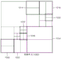
In the video data 310, the resolution is set to 1920 × 1080, the maximum size of a coding unit is set to 64, and the maximum depth is set to 2. In the video data 320, the resolution is set to 1920 × 1080, the maximum size of a coding unit is set to 64, and the maximum depth is set to 3. In the video data 330, the resolution is set to 352 × 288, the maximum size of a coding unit is set to 16, and the maximum depth is set to 1. The maximum depth shown in fig. 3 represents the total number of divisions from the maximum coding unit to the minimum coding unit.
If the resolution is high or the data amount is large, the maximum size of the coding unit may be large, thereby not only improving the coding efficiency but also accurately reflecting the features of the image. Accordingly, the maximum size of the coding unit of the video data 310 and 320 having a higher resolution than the video data 330 may be 64.
Since the maximum depth of the video data 310 is 2, since the depth is deepened to two layers by dividing the maximum coding unit twice, the coding units 315 of the video data 310 may include a maximum coding unit having a long axis size of 64 and coding units having long axis sizes of 32 and 16. Meanwhile, since the maximum depth of the video data 330 is 1, since the depth is deepened to one layer by dividing the maximum coding unit once, the coding units 335 of the video data 330 may include a maximum coding unit having a long axis size of 16 and a coding unit having a long axis size of 8.
Since the maximum depth of the video data 320 is 3, since the depth is deepened to 3 layers by dividing the maximum coding unit three times, the coding units 325 of the video data 320 may include the maximum coding unit having a long axis size of 64 and coding units having long axis sizes of 32, 16, and 8. The detailed information can be more accurately represented as the depth deepens.
Fig. 4 is a block diagram of an image encoder based on an encoding unit according to an embodiment of the present invention.
The image encoder 400 according to the embodiment performs the operation of the encoding unit determiner 120 of the video encoding apparatus 100 to encode the image data. In other words, the intra predictor 410 performs intra prediction on a coding unit in an intra mode in the current frame 405, and the motion estimator 420 and the motion compensator 425 perform inter estimation and motion compensation on a coding unit in an inter mode in the current frame 405 by using the current frame 405 and the reference frame 495.
The data output from the intra predictor 410, the motion estimator 420, and the motion compensator 425 are output as quantized transform coefficients through the frequency transformer 430 and the quantizer 440. The quantized transform coefficients are restored into data in a spatial domain through the inverse quantizer 460 and the inverse frequency transformer 470, and the restored data in the spatial domain is output as a reference frame 495 after being post-processed through the deblocking unit 480 and the loop filtering unit 490. The quantized transform coefficients may be output as a bitstream 455 by an entropy encoder 450.
In order to apply the image encoder 400 in the video encoding apparatus 100 according to the embodiment, all elements of the image encoder 400 (i.e., the intra predictor 410, the motion estimator 420, the motion compensator 425, the frequency transformer 430, the quantizer 440, the entropy encoder 450, the inverse quantizer 460, the inverse frequency transformer 470, the deblocking unit 480, and the loop filtering unit 490) must perform an operation based on each of the coding units having a tree structure while considering a maximum depth of each maximum coding unit.
Specifically, the intra predictor 410, the motion estimator 420, and the motion compensator 425 must determine the partition and the prediction mode of each of the coding units having the tree structure while considering the maximum size and the maximum depth of the current maximum coding unit, and the frequency transformer 430 must determine the size of the transform unit in each of the coding units having the tree structure.
Fig. 5 is a block diagram of an image decoder based on a coding unit according to an embodiment of the present invention.
The parser 510 parses encoded image data to be decoded and information about encoding required for decoding from the bitstream 505. In fig. 5, the parser 510 and the entropy decoder 520 are illustrated as single components, but the operations of obtaining image data and obtaining syntax information related to encoded image data performed by the parser 510 may be selectively performed by the entropy decoder 520.
The encoded image data is output as inverse quantized data through the entropy decoder 520 and the inverse quantizer 530, and the inverse quantized data is restored as image data in a spatial domain through the inverse frequency transformer 540.
The intra predictor 550 performs intra prediction on a coding unit in an intra mode with respect to image data in a spatial domain, and the motion compensator 560 performs motion compensation on a coding unit in an inter mode by using the reference frame 585.
The restored image frame data passing through the intra predictor 550 and the motion compensator 560 may be post-processed by a deblocking unit 570 and output to a Decoded Picture Buffer (DPB) 580. The DPB 580 stores the decoded image frames, so as to store reference frames, change the display order of the image frames, and output the image frames. The DPB 580 stores the decoded image frames and sets a maximum capacity of a buffer required for normal decoding of the image sequence by using a maximum decoded frame buffer syntax (max _ dec _ frame buffering) indicating a maximum buffer capacity required for normal decoding of the image frames output from the parser 510 or the entropy decoder 520.
In order to decode image data in the image data decoder 230 of the video decoding apparatus 200, the image decoder 500 according to an embodiment may perform operations performed after the operation of the parser 510 is performed.
In order to apply the image decoder 500 in the video decoding apparatus 200 according to the embodiment, all elements of the image decoder 500 (i.e., the parser 510, the entropy decoder 520, the inverse quantizer 530, the inverse frequency transformer 540, the intra predictor 550, the motion compensator 560, and the deblocking unit 570) may perform a decoding operation based on coding units having a tree structure for each maximum coding unit. Specifically, the intra predictor 550 and the motion compensator 560 may determine a partition and a prediction mode for each coding unit having a tree structure, and the inverse frequency transformer 540 may determine a size of a transform unit for each coding unit.
Fig. 6 is a diagram illustrating a deeper coding unit according to depth and a partition according to an embodiment of the present invention.
The video encoding apparatus 100 according to the embodiment and the video decoding apparatus 200 according to the embodiment use layered coding units to consider the characteristics of images. The maximum height, the maximum width, and the maximum depth of the coding unit may be adaptively determined according to the characteristics of the image, or may be set differently by a user. The size of the deeper coding unit according to the depth may be determined according to a preset maximum size of the coding unit.
In the hierarchical structure 600 of coding units according to an embodiment, the maximum height and the maximum width of a coding unit are both 64 and the maximum depth is 4. Since the depth deepens along the vertical axis of the hierarchical structure 600 of the coding unit according to the embodiment, both the height and the width of the deeper coding unit are divided. In addition, prediction units and partitions, which are the basis for predictive coding each deeper coding unit, are shown along the horizontal axis of the hierarchical structure 600 of coding units.
In other words, in the hierarchical structure 600 of coding units, the coding unit 610 is a maximum coding unit in which the depth is 0 and the size (i.e., height multiplied by width) is 64 × 64. The depth deepens along the vertical axis, and there are a coding unit 620 having a size of 32 × 32 and a depth of 1, a coding unit 630 having a size of 16 × 16 and a depth of 2, a coding unit 640 having a size of 8 × 8 and a depth of 3, and a coding unit 650 having a size of 4 × 4 and a depth of 4. The coding unit 650 having a size of 4 × 4 and a depth of 4 is a minimum coding unit.
The prediction unit and the partition of the coding unit are arranged along a horizontal axis according to each depth. In other words, if the coding unit 610 having the size of 64 × 64 and the depth of 0 is a prediction unit, the prediction unit may be divided into partitions included in the coding unit 610, i.e., a partition 610 having the size of 64 × 64, a partition 612 having the size of 64 × 32, a partition 614 having the size of 32 × 64, or a partition 616 having the size of 32 × 32.
Similarly, the prediction unit of the coding unit 620 having the size of 32 × 32 and the depth of 1 may be divided into partitions included in the coding unit 620, i.e., a partition 620 having the size of 32 × 32, a partition 622 having the size of 32 × 16, a partition 624 having the size of 16 × 32, and a partition 626 having the size of 16 × 16.
Similarly, a prediction unit of the coding unit 630 having the size of 16 × 16 and the depth of 2 may be divided into partitions included in the coding unit 630, i.e., a partition having the size of 16 × 16, a partition 632 having the size of 16 × 8, a partition 634 having the size of 8 × 16, and a partition 636 having the size of 8 × 8 included in the coding unit 630.
Similarly, the prediction unit of the coding unit 640 having the size of 8 × 8 and the depth of 3 may be divided into partitions included in the coding unit 640, i.e., partitions of size 8 × 8, partitions 642 of size 8 × 4, partitions 644 of size 4 × 8, and partitions 646 of size 4 × 4 included in the coding unit 640.
Finally, the coding unit 650 having a size of 4 × 4 and a depth of 4 is a minimum coding unit and a coding unit of a lowest depth. The prediction unit of the coding unit 650 is allocated only to the partition having the size of 4 × 4.
In order to determine the coded depth of the maximum coding unit 610, the coding unit determiner 120 of the video encoding apparatus 100 according to the embodiment must perform encoding on coding units corresponding to each depth included in the maximum coding unit 610.
As the depth deepens, the number of deeper coding units according to depth, which include data having the same range and the same size, increases. For example, four coding units corresponding to depth 2 are required to cover data included in one coding unit corresponding to depth 1. Therefore, in order to compare the encoding results of the same data according to depths, a coding unit corresponding to depth 1 and four coding units corresponding to depth 2 must both be encoded.
In order to perform encoding according to each depth, a representative encoding error, which is a minimum encoding error at a corresponding depth, may be selected by performing encoding on each prediction unit in a deeper coding unit along the horizontal axis of the hierarchical structure 600 of the coding units. Alternatively, the representative coding errors according to depths may be compared by performing coding for each depth as the depth deepens along the vertical axis of the hierarchical structure 600 of the coding unit to search for the minimum coding error. The depth and partition having the smallest coding error in the maximum coding unit 610 may be selected as the coded depth and partition type of the maximum coding unit 610.
Fig. 7 is a diagram for describing a relationship between a coding unit and a transform unit according to an embodiment of the present invention.
The video encoding apparatus 100 according to the embodiment or the video decoding apparatus 200 according to the embodiment encodes or decodes an image according to a coding unit having a size smaller than or equal to a maximum coding unit for each maximum coding unit. The size of the transform unit for frequency transform during encoding may be selected based on a data unit that is not larger than the corresponding coding unit.
For example, in the video encoding apparatus 100 according to the embodiment or the video decoding apparatus 200 according to the embodiment, if the size of the current coding unit 710 is 64 × 64, frequency transform may be performed by using the transform unit 720 having the size of 32 × 32.
Also, data of the coding unit 710 having the size of 64 × 64 may be encoded by performing frequency transform on each of the transform units having the sizes of 32 × 32, 16 × 16, 8 × 8, and 4 × 4 smaller than 64 × 64, and then the transform unit having the smallest error may be selected.
Fig. 8 is a diagram for describing coding information of a coding unit corresponding to a coded depth according to an embodiment of the present invention.
The output unit 130 of the video encoding apparatus 100 according to the embodiment may encode information 800 regarding a partition type, information 810 regarding a prediction mode, and information 820 regarding a transform unit size of each coding unit corresponding to a coded depth, and transmit the information 800, the information 810, and the information 820 as information regarding a coding mode.
The information on the partition type 800 indicates information on the shape of a partition obtained by dividing a prediction unit of a current coding unit, wherein the partition is a data unit used for prediction coding of the current coding unit. For example, the current coding unit CU _0 of size 2N × 2N may be divided into any one of the following partitions: a partition 802 of size 2N × 2N, a partition 804 of size 2N × N, a partition 806 of size N × 2N, and a partition 808 of size N × N. Here, the information 800 regarding the partition type of the current coding unit is set to indicate one of the following partitions: a partition 804 of size 2N × N, a partition 806 of size N × 2N, and a partition 808 of size N × N.
The information on the prediction mode 810 indicates a prediction mode of each partition. For example, the information 810 on the prediction mode may indicate a mode of prediction encoding performed on the partition indicated by the information 800, i.e., an intra mode 812, an inter mode 814, or a skip mode 816.
Also, the information 820 regarding the transform unit size indicates a transform unit on which frequency transform is based when performing frequency transform on the current coding unit. For example, the transform unit may be the first intra transform unit 822, the second intra transform unit 824, the first inter transform unit 826, or the second intra transform unit 828.
The image data and coding information extractor 220 of the video decoding apparatus 200 according to the embodiment may extract and use information 800 regarding a partition type, information 810 regarding a prediction mode, and information 820 regarding a transform unit size for decoding, according to each deeper coding unit.
Fig. 9 is a diagram of a deeper coding unit according to depth according to an embodiment of the present invention.
The partitioning information may be used to indicate a change in depth. The partition information indicates whether the coding unit of the current depth is partitioned into coding units of lower depths.
The prediction unit 910 for prediction encoding the coding unit 900 having a depth of 0 and a size of 2N _0 × 2N _0 may include partitions of the following partition types: a partition type 912 having a size of 2N _0 × 2N _0, a partition type 914 having a size of 2N _0 × N _0, a partition type 916 having a size of N _0 × 2N _0, and a partition type 918 having a size of N _0 × N _ 0. Fig. 9 shows only partition types 912 to 918 obtained by symmetrically dividing the prediction unit 910, but the partition types are not limited thereto, and the partitions of the prediction unit 910 may include asymmetric partitions, partitions having a predetermined shape, and partitions having a geometric shape.
According to each partition type, prediction encoding is repeatedly performed on one partition having a size of 2N _0 × 2N _0, two partitions having a size of 2N _0 × N _0, two partitions having a size of N _0 × 2N _0, and four partitions having a size of N _0 × N _ 0. The prediction encoding in the intra mode and the inter mode may be performed on partitions having sizes of 2N _0 × 2N _0, 2N _0 × N _0, and N _0 × N _ 0. The prediction encoding in the skip mode is performed only on partitions having a size of 2N _0 × 2N _ 0.
If the encoding error is the smallest in one of the partition types 912 to 916 of sizes 2N _0 × 2N _0, 2N _0 × N _0, and N _0 × 2N _0, the prediction unit 910 may not be divided to a lower depth.
If the coding error is minimum in the partition type 918 of size N _0 × N _0, the depth may be changed from 0 to 1 to divide the partition type 918 in operation 920 and repeatedly perform coding on the coding unit 930 of depth 2 and size N _0 × N _0 to search for the minimum coding error.
The prediction unit 940 for prediction encoding the coding unit 930 having a depth of 1 and a size of 2N _1 × 2N _1(═ N _0 × N _0) may include partitions of the following partition types: a partition type 942 of size 2N _1 × 2N _1, a partition type 944 of size 2N _1 × N _1, a partition type 946 of size N _1 × 2N _1, and a partition type 948 of size N _1 × N _ 1.
If the coding error is minimum in the partition type 948 of size N _1 × N _1, the depth is changed from 1 to 2 to divide the partition type 948 in operation 950, and the coding is repeatedly performed on the coding unit 960 of depth 2 and size N _2 × N _2 to search for the minimum coding error.
When the maximum depth is d, the partition information according to each depth may be set until the depth becomes d-1, and the partition information may be set until the depth becomes d-2. In other words, when encoding is performed until the depth is d-1 after the coding unit corresponding to the depth of d-2 is divided in operation 970, the prediction unit 990 for prediction-encoding the coding unit 980 having the depth of d-1 and the size of 2N _ (d-1) × 2N _ (d-1) may include partitions of the following partition types: partition type 992 of size 2N _ (d-1). times.2N _ (d-1), partition type 994 of size 2N _ (d-1). times.N _ (d-1), partition type 996 of size N _ (d-1). times.2N _ (d-1), and partition type 998 of size N _ (d-1). times.N _ (d-1).
Predictive encoding may be repeatedly performed on one partition of size 2N _ (d-1) × 2N _ (d-1), two partitions of size 2N _ (d-1) × N _ (d-1), two partitions of size N _ (d-1) × 2N _ (d-1), and four partitions of size N _ (d-1) × N _ (d-1) among the partition types 992 to 998 to search for a partition type having a minimum encoding error.
Even when the partition type 998 of size N _ (d-1) × N _ (d-1) has the minimum coding error, since the maximum depth is d, the coding unit CU _ (d-1) of depth d-1 is not divided to a lower depth any more, the coding depth for the current maximum coding unit 900 is determined to be d-1, and the partition type of the current maximum coding unit 900 may be determined to be N _ (d-1) × N _ (d-1). Also, since the maximum depth is d, partition information of the coding unit 952 having a depth of d-1 is not set.
The data unit 999 may be referred to as a "minimum unit" for the current maximum coding unit. The minimum unit according to the embodiment may be a rectangular data unit obtained by dividing the minimum coding unit having the lowest coded depth into 4. By repeatedly performing encoding, the video encoding apparatus 100 may determine a coded depth by selecting a depth having a minimum coding error by comparing coding errors according to depths of the coding unit 900, and set a corresponding partition type and a prediction mode as a coding mode of the coded depth.
In this way, the minimum coding errors according to depths are compared in all depths 1 to d, and the depth having the minimum coding error may be determined as a coded depth. The coded depth, the partition type of the prediction unit, and the prediction mode may be encoded and transmitted as information on the encoding mode. In addition, since the coding unit must be divided from a depth of 0 to a coded depth, it is necessary to set only division information of the coded depth to 0 and set division information of depths other than the coded depth to 1.
The image data and coding information extractor 220 of the video decoding apparatus 200 according to the embodiment may extract and use information about the coded depth and the prediction unit of the coding unit 900 to decode the coding unit 912. The video decoding apparatus 200 according to the embodiment may perform decoding by determining a depth, of which division information is 0, as a coded depth using division information according to depths, and using information regarding a coding mode of the corresponding depth.
Fig. 10 to 12 are diagrams for describing a relationship between an encoding unit, a prediction unit, and a frequency transform unit according to an embodiment of the present invention.
The coding unit 1010 is a coding unit corresponding to a coded depth determined by the video encoding apparatus 100 according to the embodiment among maximum coding units. The prediction unit 1060 is a partition of the prediction unit of each coding unit 1010, and the transform unit 1070 is a transform unit of each coding unit 1010.
When the depth of the maximum coding unit is 0 in the coding unit 1010, the depths of the coding units 1012 and 1054 are 1, the depths of the coding units 1014, 1016, 1018, 1028, 1050, and 1052 are 2, the depths of the coding units 1020, 1022, 1024, 1026, 1030, 1032, and 1048 are 3, and the depths of the coding units 1040, 1042, 1044, and 1046 are 4.
In the prediction unit 1060, some partitions 1014, 1016, 1022, 1032, 1048, 1050, 1052, and 1054 are obtained by dividing the coding unit. In other words, the size of the partition type in the partitions 1014, 1022, 1050, and 1054 is 2N × N, the size of the partition type in the partitions 1016, 1048, and 1052 is N × 2N, and the size of the partition type of the partition 1032 is N × N. The prediction unit and partition of the coding unit 1010 are less than or equal to each coding unit.
In the transform unit 1070 in a data unit smaller than the encoding unit 1052, frequency transform or inverse frequency transform is performed on the image data of the encoding unit 1052. In addition, the transform units 1014, 1016, 1022, 1032, 1048, 1050, and 1052 in the transform unit 1070 are different from the transform units 1014, 1016, 1022, 1032, 1048, 1050, and 1052 in the prediction unit 1060 in terms of size or shape. In other words, the video encoding apparatus 100 according to the embodiment and the video decoding apparatus 200 according to the embodiment may independently perform intra prediction/motion estimation/motion compensation and frequency transformation/inverse frequency transformation on data units in the same coding unit.
Accordingly, encoding is recursively performed on each coding unit having a hierarchical structure in each region of the largest coding unit to determine an optimal coding unit, so that coding units having a recursive tree structure can be obtained. The encoding information may include partition information on the coding unit, information on a partition type, information on a prediction mode, and information on a size of the transform unit. Table 1 shows encoding information that can be set by the video encoding apparatus 100 according to the embodiment and the video decoding apparatus 200 according to the embodiment.
[ Table 1]


The output unit 130 of the video encoding apparatus 100 according to the embodiment may output encoding information regarding coding units having a tree structure, and the image data and encoding information extractor 220 of the video decoding apparatus 200 according to the embodiment may extract encoding information regarding coding units having a tree structure from a received bitstream.
The partition information indicates whether to partition the current coding unit into coding units of lower depths. If the partition information of the current depth d is 0, depths at which the current coding unit is no longer partitioned into lower depths are coded depths, so that information on partition types, prediction modes, and sizes of transform units may be defined for the coded depths. If the current coding unit is further divided according to the division information, encoding is independently performed on four divided coding units of lower depths.
The prediction mode may be one of an intra mode, an inter mode, and a skip mode. The intra mode and the inter mode may be defined in all partition types, and the skip mode is defined only in a partition type having a size of 2N × 2N.
The information on the partition type may indicate symmetric partition types having sizes of 2N × 2N, 2N × N, N × 2N, and N × N obtained by symmetrically dividing the height or width of the prediction unit, and asymmetric partition types having sizes of 2N × nU, 2N × nD, nL × 2N, and nR × 2N obtained by asymmetrically dividing the height or width of the prediction unit. The asymmetric partition types of sizes of 2 nxnu and 2 nxnd may be obtained by dividing the height of the prediction unit by 1:3 and 3:1, respectively, and the asymmetric partition types of sizes nL × 2N and nR × 2N may be obtained by dividing the width of the prediction unit by 1:3 and 3:1, respectively.
The size of the transform unit may be set to two types in the intra mode and two types in the inter mode. In other words, if the partition information of the transform unit is 0, the size of the transform unit may be set to 2N × 2N, i.e., the size of the current coding unit. If the partition information of the transform unit is 1, the transform unit may be obtained by partitioning the current coding unit. In addition, the size of the transform unit may be set to N × N if the partition type of the current coding unit having the size of 2N × 2N is a symmetric partition type, and may be set to N/2 × N/2 if the partition type of the current coding unit is an asymmetric partition type.
The encoding information regarding the coding units having the tree structure according to the embodiment may be allocated to at least one of a coding unit, a prediction unit, and a minimum unit corresponding to a coded depth. The coding unit corresponding to the coded depth may include at least one of a prediction unit and a minimum unit including the same coding information.
Accordingly, whether the neighboring data units are included in the same coding unit corresponding to the coded depth is determined by comparing the coding information of the neighboring data units. In addition, a corresponding coding unit corresponding to the coded depth is determined by using the coding information of the data unit, and thus the distribution of coded depths in the maximum coding unit may be determined.
Accordingly, if the current coding unit is predicted by referring to neighboring data units, the coding information of data units in deeper coding units neighboring the current coding unit can be directly referred to and used.
Alternatively, if the current coding unit is prediction-encoded by referring to neighboring data units, data units neighboring the current coding unit among deeper coding units are searched by using encoding information of data units neighboring the current coding unit, and the searched neighboring coding units may be referred to for prediction-encoding the current coding unit.
Fig. 13 is a diagram for describing a relationship among a coding unit, a prediction unit, and a transform unit according to the coding mode information of table 1.
The maximum coding unit 1300 includes coding units 1302, 1304, 1306, 1312, 1314, 1316, and 1318 of multiple coded depths. Here, since the coding unit 1318 is a coding unit of one coded depth, the partition information may be set to 0. The information on the partition type of the coding unit 1318 having a size of 2N × 2N may be set to one of the following partition types: a partition type 1322 of size 2N × 2N, a partition type 1324 of size 2N × N, a partition type 1326 of size N × 2N, a partition type 1328 of size N × N, a partition type 1332 of size 2N × nU, a partition type 1334 of size 2N × nD, a partition type 1336 of size nL × 2N, and a partition type 1338 of size nR × 2N.
When the partition type is set to be symmetrical, i.e., a partition type 1322 having a size of 2N × 2N, a partition type 1326 having a size of N × 2N, or a partition type 1328 having a size of N × N, if partition information (TU size flag) of a transform unit is 0, a transform unit 1342 having a size of 2N × 2N may be set, and if TU size flag is 1, a transform unit 1344 having a size of N × N may be set.
When the partition type is set to be asymmetric (i.e., a partition type 1332 of size 2N × nU, a partition type 1334 of size 2N × nD, a partition type 1336 of size nL × 2N, or a partition type 1338 of size nR × 2N), a transform unit 1352 of size 2N × 2N may be set if the TU size flag is 0, and a transform unit 1354 of size N/2 × N/2 may be set if the TU size flag is 1.
Fig. 14 is a diagram of a video encoding apparatus having temporal scalability according to an embodiment of the present invention.
Referring to fig. 14, the video encoding apparatus 1400 according to an embodiment includes a video encoder 1410 and a multiplexer 1420.
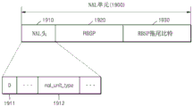
The video encoder 1410 corresponds to the above-described video encoding apparatus 100 of fig. 1, and the VCL operating the encoding process of the video data encodes the video data based on the above-described layered coding unit. The multiplexer 1420 multiplexes the video data by using such transmission data units: the transmission data unit is suitable for the protocol of a communication channel or the storage format of a storage medium, a video editing system or a media framework. As will be described below, the multiplexer 1420 may transmit video data by using a Network Abstraction Layer (NAL) unit, which is a transport unit in a NAL.
In order to provide video data with temporal scalability, the video encoder 1410 may divide pictures included in a picture sequence into temporal sub-layers. The temporal sublayer denotes a group of NAL units including pictures having the same temporal identifier (temporal _ id) or information on such pictures.
The multiplexer 1420 may classify the temporal layer access picture as the first temporal layer access picture or the second temporal layer access picture based on whether a picture that is encoded after the temporal layer access picture and belongs to the same temporal sublayer as the temporal layer access picture or belongs to a temporal sublayer higher than the temporal layer access picture can refer to a picture that is encoded before the temporal layer access picture, and the multiplexer 1420 may add type syntax information for identifying the first temporal layer access picture and the second temporal layer access picture to transmission unit data including the temporal layer access picture. The decoding order and the encoding order represent the order in which pictures are processed by the decoder and the encoder, respectively, and the encoding order may be the same as the decoding order. Thus, in describing the present invention, the encoding order may represent the decoding order, and vice versa.
The temporal layer access picture is a picture in which: the picture is first encoded (or decoded) after the up-switch by being included in a higher temporal sublayer that is accessed in the event of a switch from a lower temporal sublayer to a higher temporal sublayer. As will be described later, the temporal layer access picture is a picture in which: the picture refers to a picture that is available at least when an up-switch occurs. The first temporal layer access picture represents a temporal layer access picture in which pictures encoded after the temporal layer access picture and belonging to the same temporal sub-layer as the temporal layer access picture or belonging to a temporal sub-layer higher than the temporal layer access picture can refer to pictures encoded before the temporal layer access picture. The second temporal layer access picture represents a temporal layer access picture in which pictures encoded after the temporal layer access picture and belonging to the same temporal sub-layer as the temporal layer access picture or belonging to a temporal sub-layer higher than the temporal layer access picture cannot refer to pictures encoded before the temporal layer access picture.
Fig. 15 is a diagram of pictures divided into temporal sub-layers included in a picture sequence according to an embodiment of the present invention. In fig. 15 and 16, I, B and P denote an I picture, a B picture, and a P picture, respectively, and the numbers following I, B or P denote the numbers of the display order. In fig. 15, the direction of the arrow indicates a reference direction. For example, the I0 picture 1500 is used as a reference picture for the B1 picture 1531.
Referring to fig. 15, the video encoder 1410 may provide video data having temporal scalability by classifying I0 pictures 1500 through B7 pictures 1534 included in a picture sequence into temporal sub-layers and allocating temporal _ ids to I0 pictures 1500 through B7 pictures 1534 included in each temporal sub-layer.
In detail, the value of temporal _ id of the I0 picture 1500 and the P8 picture 1501 belonging to the lowest temporal sublayer is set to 0. The B4 picture 1510 belongs to a temporal sub-layer with temporal _ id of 1. The B2 picture 1520 and the B6 picture 1521 belong to a temporal sublayer whose temporal _ id is 2. The B1 picture 1531, the B3 picture 1532, the B5 picture 1533, and the B7 picture 1534 belong to a temporal sub-layer whose temporal _ id is 3.
Fig. 16 is a diagram of a screen displayed according to a frame rate according to an embodiment of the present invention.
Referring to fig. 15 and 16, when the frame rate is 7.5Hz, I0 pictures and P8 pictures at the lowest temporal sub-layer and with temporal _ id of 0 are displayed. When the frame rate is 15Hz, B4 pictures with temporal _ id of 1 and I0 and P8 pictures with temporal _ id of 0 are displayed. When the frame rate is 30Hz, I0, B2, B4, B6 and P8 pictures, whose temporal _ id is 0, 1 and 2, are displayed. When the frame rate is 60Hz, I0, B1, B2, B3, B4, B5, B6, B7, and P8 pictures, whose temporal _ id is 0, 1, 2, and 4, are displayed.
In this way, temporal scalability can be achieved by decoding all pictures having temploral _ id lower than or equal to a predetermined value according to a frame rate and displaying the decoded pictures. In other words, temporal scalability can be achieved by decoding pictures included in all temporal sublayers lower than or equal to a higher temporal sublayer of which temporal _ id is a predetermined value according to a frame rate and displaying the decoded pictures.
The change in frame rate may be defined as temporal layer switching. A change from a low frame rate to a high frame rate is defined as temporal layer up-switching, and a change from a high frame rate to a low frame rate is defined as temporal layer down-switching. Since the temporal layer down-switching can be performed by removing pictures whose temporal _ id is higher than a predetermined value, the temporal layer down-switching can be performed at any time. For example, referring back to fig. 16, when the frame rate is changed from 30Hz to 7.5Hz, temporal layer down-switching may be performed by selecting and displaying only I0 and P8 pictures by excluding pictures having a temporal _ id equal to or higher than 1 (i.e., B2, B4, and B6 pictures) from among I0, B2, B4, B6, and P8 pictures having a temporal _ id of 0, 1, and 2.
On the other hand, temporal layer up-switching is not always possible. For example, if a picture belonging to a higher temporal sub-layer refers to a future upper layer (future upper) picture that is not available during an up-switch, the picture belonging to the higher temporal sub-layer cannot be decoded. It is assumed that temporal layer up-switching occurs from a temporal sub-layer with a temporal _ id of 0 to a higher temporal sub-layer with a temporal _ id of 1. Temporal sub-layer up-switching cannot be performed if a picture belonging to a higher temporal sub-layer whose temporal _ id is 1 refers to a picture belonging to a further upper temporal sub-layer whose temporal _ id is at least 2 as a reference picture.
Therefore, such pictures should be used as temporal layer access pictures: the picture refers to a picture available at least during temporal sub-layer up-switching among pictures belonging to a higher temporal sub-layer.
In order to improve the prediction efficiency of a picture that is encoded (or decoded) after a temporal layer access picture, a picture that is encoded after the temporal layer access picture and belongs to the same temporal sub-layer as the temporal layer access picture or belongs to a temporal sub-layer higher than the temporal layer access picture may refer to a picture that is encoded before the temporal layer access picture. Here, if the number of candidates available as a reference picture is increased, since a reference picture similar to a picture to be encoded is more likely to be used, prediction efficiency of an image can be improved by increasing the likelihood of reference. The temporal layer access picture allowing such reference is defined as a first temporal layer access picture. In other words, the first temporal layer access picture is a temporal layer access picture in which: the temporal layer access picture allows pictures that are coded after the temporal layer access picture and belong to the same temporal sub-layer as the temporal layer access picture or belong to a higher temporal sub-layer than the temporal layer access picture to reference pictures that are coded before the temporal layer access picture. On the other hand, a temporal layer access picture in which such reference is restricted is defined as a second temporal layer access picture. In other words, the second temporal layer access picture is a temporal layer access picture that: the temporal layer access picture does not allow pictures that are coded after the temporal layer access picture and belong to the same temporal sub-layer as the temporal layer access picture or belong to a higher temporal sub-layer than the temporal layer access picture to reference pictures that are coded before the temporal layer access picture.
Fig. 17 is a diagram for describing a leader picture and a first time layer visit according to an embodiment of the present invention. As described above, I, B and P denote I picture, B picture, and P picture, respectively, and the numbers following I, B and P denote the numbers of the display order. Further, the direction of the arrow indicates a reference direction.
The leading picture of the predetermined picture represents a picture that is decoded after the predetermined picture but is displayed before the predetermined picture. Referring to fig. 17, a B3 picture 1720 is a leader picture that is displayed before the B4 picture 1710 but is decoded after the B4 picture 1710. Here, it is assumed that the B3 picture 1720 is bidirectionally predicted by referring to the B2 picture and the B4 picture 1710. Since the B3 picture 1720, which belongs to the same temporal sublayer or a higher temporal sublayer and is decoded after the B4 picture 1710 according to the decoding order, refers to the B2 picture decoded before the B4 picture 1710, the B4 picture 1710 can be classified as a first temporal layer access picture.
As described above, the number of pictures that can be used as reference pictures can be increased to increase the prediction efficiency of an image, but in the case where pictures are accessed for a first temporal layer, pictures that are no longer needed during the decoding process can be decoded according to the reference relationship between pictures during temporal layer up-switching.
Fig. 18 is a diagram for describing a leading picture that cannot be decoded during temporal layer up-switching according to an embodiment of the present invention.
Referring to fig. 18, it is assumed that a B4 picture 1810 is a temporal layer access picture in the case where a temporal layer up-switch is performed from the lowest temporal sublayer to the immediately higher temporal sublayer. Further, it is assumed that the B4 picture 1810 is a first temporal layer access picture in which pictures decoded after the B4 picture 1810 and belonging to the same temporal sub-layer as the B4 picture 1810 or to a temporal sub-layer higher than the B4 picture 1810 can refer to pictures decoded before the B4 picture 1810. If temporal layer up-switching is performed, the B3 picture 1820, which is a leading picture of the B4 picture 1810, cannot be decoded because there is no reference picture. Accordingly, in the case of the first time layer access picture, since pictures to be subsequently decoded are not constrained to refer to pictures that were decoded before the first time layer access picture, there may be a leading picture that cannot be subsequently decoded according to a reference relationship between the pictures.
The multiplexer 1420 of the video encoding apparatus 1400 according to the embodiment may separately classify pictures that cannot be decoded during temporal layer up-switching related to the first temporal layer access picture as discardable pictures, and may set a predetermined syntax "NAL _ unit _ type" to a header of a NAL unit to indicate the discardable pictures. For example, the B3 picture 1820 of fig. 18 may be classified as a discardable picture during temporal layer up-switching.
Pictures that cannot be decoded during temporal layer up-switching are classified as discardable pictures, so that hardware resources can be saved by skipping a separate decoding process in the case where a decoding apparatus receives a NAL unit including the discardable pictures.
The multiplexer 1420 adds first type syntax information (NAL _ unit _ type) indicating that the first temporal layer access picture is included to a header of a NAL unit including the first temporal layer access picture, and adds second type syntax information (NAL _ unit _ type) indicating that the second temporal layer access picture is included to a header of transmission unit data including the second temporal layer access picture.
Fig. 19 is a diagram of a NAL unit according to an embodiment of the present invention.
Referring to fig. 19, a NAL unit 1900 includes a NAL header 1910 and a Raw Byte Sequence Payload (RBSP) 1920. The RBSP tail bits 1930 are length adjustment bits added after the RBSP1920 to represent the length of the RBSP1920 in multiples of 8 bits. The RBSP trailing bits 1930 may start with "1" and then may include consecutive "0" s determined based on the length of the RBSP1920 so as to have a form such as "100 …", and by searching for "1" as an initial bit value, the position of the last bit of the RBSP1920 immediately before the "1" may be determined.
Syntax "NAL _ unit _ type" 1912 for identifying whether the first temporal layer access picture, the second temporal layer access picture, and the discardable picture are included in the NAL unit 1900 and syntax "forbidden _ zero _ bit" 1911 having a value of 0 may be set to the NAL header 1910. In other words, NAL units having an inherent syntax of "NAL _ unit _ type" for transmitting a first temporal layer access picture, a second temporal layer access picture, and a discardable picture may be used.
Table 2 below shows an example of a NAL unit 1900 according to the value of syntax "NAL _ unit _ type".
[ Table 2]


Referring to table 2, when a temporal layer access picture according to an embodiment of the present invention is a broken link temporal layer access (BLT) picture, each of a first temporal layer access picture and a second temporal layer access picture may be inserted into and transmitted using NAL units having values of 6 and 7 in a syntax "NAL _ unit _ type".
Further, when the discardable picture is marked as a discarded (TFD) picture, the discardable picture may be inserted into and transmitted with a NAL unit having a value of 2 of syntax "NAL _ unit _ type".
Fig. 20 is a flowchart illustrating a video encoding method with temporal scalability according to an embodiment of the present invention.
Referring to fig. 20, a video encoder 1410 encodes a picture included in a picture sequence, divides the encoded picture into temporal sub-layers, and outputs the encoded picture in operation 2010.
In operation 2020, the multiplexer 1420 classifies the temporal layer access picture as the first temporal layer access picture or the second temporal layer access picture based on whether a picture that is encoded after the temporal layer access picture and belongs to the same temporal sub-layer as the temporal layer access picture or belongs to a temporal sub-layer higher than the temporal layer access picture can refer to a picture that is encoded before the temporal layer access picture. As described above, the first temporal layer access picture represents a temporal layer access picture in which: the temporal layer access picture allows pictures that are coded after the temporal layer access picture and belong to the same temporal sub-layer as the temporal layer access picture or belong to a higher temporal sub-layer than the temporal layer access picture to reference pictures that are coded before the temporal layer access picture. The second temporal layer access picture represents a temporal layer access picture that: the temporal layer access picture does not allow pictures that are coded after the temporal layer access picture and belong to the same temporal sub-layer as the temporal layer access picture or belong to a higher temporal sub-layer than the temporal layer access picture to refer to pictures that are coded before the temporal layer access picture.
In operation 2030, the multiplexer 1420 adds type syntax information for identifying the first temporal layer access picture and the second temporal layer access picture to transmission unit data including the temporal layer access picture. As described above, the multiplexer 1420 can transmit the first temporal layer access picture, the second temporal layer access picture, and the discardable picture using a NAL unit having a native syntax "NAL _ unit _ type".
Fig. 21 is a diagram of a video decoding apparatus having temporal scalability according to an embodiment of the present invention.
Referring to fig. 21, the video decoding apparatus 2100 according to an embodiment includes a video decoder 2130, an inverse multiplexer 2120, and a receiver 2110.
The receiver 2110 receives transmission unit data (i.e., NAL unit data) from the video encoding apparatus 1400 of fig. 14.
The inverse multiplexer 2120 may determine the type of a picture included in the transmission unit data by using an identifier included in the transmission unit data. As described above, the inverse multiplexer 2120 may determine a NAL unit including a first temporal layer access picture, a second temporal layer access picture, and a discardable picture based on the syntax "NAL _ unit _ type".
The video decoder 2130 corresponds to the video decoding apparatus 200 of fig. 2 or the image decoder 500 of fig. 5, and decodes a received picture by obtaining the following information for a coding unit used to generate image data and coded data: partition information, information on partition types, information on prediction modes, information on transform unit sizes, and information on parameter sets related to encoding processes.
Fig. 22 is a flowchart illustrating a video decoding method with temporal scalability according to an embodiment of the present invention.
Referring to fig. 22, a receiver 2110 receives transmission unit data obtained by dividing and encoding a picture included in a picture sequence into temporal sub-layers in operation 2210.
In operation 2220, the inverse multiplexer 2120 identifies transmission unit data by using type syntax information included in the transmission unit data: the transport unit data includes temporal layer access pictures accessed for temporal layer up-switching from a lower temporal sublayer to a higher temporal sublayer.
Embodiments according to the present invention can be written as computer programs and can be implemented in general-use digital computers that execute the programs using a computer readable recording medium. Examples of the computer-readable recording medium include magnetic storage media (e.g., Read Only Memory (ROM), floppy disks, and hard disks), optical recording media (e.g., compact disk read only memory (CD-ROM) and Digital Versatile Disks (DVDs)), and carrier waves (such as data transmission through the internet).
While the present invention has been particularly shown and described with reference to exemplary embodiments thereof, it will be understood by those of ordinary skill in the art that various changes in form and details may be made therein without departing from the spirit and scope of the present invention as defined by the following claims. The exemplary embodiments should be considered in descriptive sense only and not for purposes of limitation. Therefore, the scope of the invention is defined not by the detailed description of the invention but by the appended claims, and all differences within the scope will be construed as being included in the present invention.
Claims (4)
1. A video decoding apparatus, the video decoding apparatus comprising:
a receiver that receives transmission unit data;
an inverse multiplexer identifying a type of a current picture included in the transmission unit data by using type syntax information included in the transmission unit data, wherein the transmission unit data includes a temporal layer access picture accessed to perform temporal layer up-switching from a lower temporal sublayer to a higher temporal sublayer;
a decoder for decoding the current picture based on the identified type,
wherein the type syntax information indicates whether the current picture is a first temporal layer access picture or a second temporal layer access picture,
wherein, when the type syntax information indicates that the type of the current picture is the first temporal layer access picture, a first picture, which is decoded after the first temporal layer access picture and belongs to a temporal sub-layer higher than a temporal sub-layer of the first temporal layer access picture, can refer to a second picture, which is decoded before the first temporal layer access picture,
when the type syntax information indicates that the type of the current picture is the second temporal layer access picture, a third picture, which is decoded after the second temporal layer access picture and belongs to a temporal sub-layer higher than a temporal sub-layer of the second temporal layer access picture, cannot refer to a picture decoded before the second temporal layer access picture,
wherein:
the picture is divided into a plurality of maximum coding units according to information on the maximum size of the coding units,
a current maximum coding unit of the plurality of maximum coding units is hierarchically divided into one or more coding units according to depths according to the division information, wherein the depths include at least one of a current depth and a lower depth,
when the partition information indicates that the partition is performed with respect to the current depth, the coding unit of the current depth is partitioned into four coding units of lower depths independently of neighboring coding units,
when the partition information indicates that no partition is performed for the current depth, one or more prediction units and one or more transform units are obtained from a coding unit of the current depth.
2. A video encoding method for encoding video with temporal scalability, the video encoding method comprising:
encoding pictures included in a picture sequence;
identifying a temporal layer access picture as a first temporal layer access picture or a second temporal layer access picture;
generating a bitstream, wherein the bitstream includes transmission unit data and type syntax information indicating a type of a current picture included in the transmission unit data, the transmission unit data includes a temporal layer access picture accessed for temporal layer up-switching from a lower temporal sublayer to a higher temporal sublayer,
wherein the type syntax information indicates whether the current picture is a first temporal layer access picture or a second temporal layer access picture,
wherein, when the type syntax information indicates that the type of the current picture is the first temporal layer access picture, a first picture, which is decoded after the first temporal layer access picture and belongs to a temporal sub-layer higher than a temporal sub-layer of the first temporal layer access picture, can refer to a second picture, which is decoded before the first temporal layer access picture,
when the type syntax information indicates that the type of the current picture is the second temporal layer access picture, a third picture, which is decoded after the second temporal layer access picture and belongs to a temporal sub-layer higher than a temporal sub-layer of the second temporal layer access picture, cannot refer to a picture decoded before the second temporal layer access picture,
wherein:
the picture is divided into a plurality of maximum coding units according to information on the maximum size of the coding units,
a current maximum coding unit of the plurality of maximum coding units is hierarchically divided into one or more coding units according to depths according to the division information, wherein the depths include at least one of a current depth and a lower depth,
when the partition information indicates that the partition is performed with respect to the current depth, the coding unit of the current depth is partitioned into four coding units of lower depths independently of neighboring coding units,
when the partition information indicates that no partition is performed for the current depth, one or more prediction units and one or more transform units are obtained from a coding unit of the current depth.
3. A video encoding apparatus for encoding video with temporal scalability, the video encoding apparatus comprising:
a video encoder which encodes pictures included in the picture sequence;
a multiplexer identifying a type of a current picture, wherein the type includes a first temporal layer access picture or a second temporal layer access picture; and generating a bitstream, wherein the bitstream includes transmission unit data and type syntax information indicating a type of a current picture included in the transmission unit data, the transmission unit data includes a temporal layer access picture accessed for temporal layer up-switching from a lower temporal sublayer to a higher temporal sublayer,
wherein the type syntax information indicates whether the current picture is a first temporal layer access picture or a second temporal layer access picture,
wherein, when the type syntax information indicates that the type of the current picture is the first temporal layer access picture, a first picture, which is decoded after the first temporal layer access picture and belongs to a temporal sub-layer higher than a temporal sub-layer of the first temporal layer access picture, can refer to a second picture, which is decoded before the first temporal layer access picture,
when the type syntax information indicates that the type of the current picture is the second temporal layer access picture, a third picture, which is decoded after the second temporal layer access picture and belongs to a temporal sub-layer higher than a temporal sub-layer of the second temporal layer access picture, cannot refer to a picture decoded before the second temporal layer access picture,
wherein:
the picture is divided into a plurality of maximum coding units according to information on the maximum size of the coding units,
a current maximum coding unit of the plurality of maximum coding units is hierarchically divided into one or more coding units according to depths according to the division information, wherein the depths include at least one of a current depth and a lower depth,
when the partition information indicates that the partition is performed with respect to the current depth, the coding unit of the current depth is partitioned into four coding units of lower depths independently of neighboring coding units,
when the partition information indicates that no partition is performed for the current depth, one or more prediction units and one or more transform units are obtained from a coding unit of the current depth.
4. A computer-readable storage medium storing a computer program which, when executed by a processor, performs a method of decoding an image, the method comprising:
receiving transmission unit data, wherein the transmission unit data is obtained by dividing a picture included in a picture sequence into temporal sub-layers and encoding the picture;
identifying a type of a current picture included in the transmission unit data by using type syntax information included in the transmission unit data, the transmission unit data including a temporal layer access picture accessed to perform temporal layer up-switching from a lower temporal sublayer to a higher temporal sublayer; and
decoding the current picture based on the identified type,
wherein the type syntax information indicates whether the current picture is a first temporal layer access picture or a second temporal layer access picture,
wherein, when the type syntax information indicates that the type of the current picture is the first temporal layer access picture, a first picture, which is decoded after the first temporal layer access picture and belongs to a temporal sub-layer higher than a temporal sub-layer of the first temporal layer access picture, can refer to a second picture, which is decoded before the first temporal layer access picture,
when the type syntax information indicates that the type of the current picture is the second temporal layer access picture, a third picture, which is decoded after the second temporal layer access picture and belongs to a temporal sub-layer higher than a temporal sub-layer of the second temporal layer access picture, cannot refer to a picture decoded before the second temporal layer access picture,
wherein:
the picture is divided into a plurality of maximum coding units according to information on the maximum size of the coding units,
a current maximum coding unit of the plurality of maximum coding units is hierarchically divided into one or more coding units according to depths according to the division information, wherein the depths include at least one of a current depth and a lower depth,
when the partition information indicates that the partition is performed with respect to the current depth, the coding unit of the current depth is partitioned into four coding units of lower depths independently of neighboring coding units,
when the partition information indicates that no partition is performed for the current depth, one or more prediction units and one or more transform units are obtained from a coding unit of the current depth.
Applications Claiming Priority (3)
| Application Number | Priority Date | Filing Date | Title |
|---|---|---|---|
| US201261667654P | 2012-07-03 | 2012-07-03 | |
| US61/667,654 | 2012-07-03 | ||
| CN201380045893.5A CN104604226B (en) | 2012-07-03 | 2013-07-03 | Decoded method is carried out to video with time scalability |
Related Parent Applications (1)
| Application Number | Title | Priority Date | Filing Date |
|---|---|---|---|
| CN201380045893.5A Division CN104604226B (en) | 2012-07-03 | 2013-07-03 | Decoded method is carried out to video with time scalability |
Publications (2)
| Publication Number | Publication Date |
|---|---|
| CN108174224A CN108174224A (en) | 2018-06-15 |
| CN108174224B true CN108174224B (en) | 2020-10-27 |
Family
ID=49882249
Family Applications (5)
| Application Number | Title | Priority Date | Filing Date |
|---|---|---|---|
| CN201810252021.0A Active CN108235034B (en) | 2012-07-03 | 2013-07-03 | Video encoding method and apparatus, and video decoding method and apparatus |
| CN201810252034.8A Active CN108235035B (en) | 2012-07-03 | 2013-07-03 | Video encoding method and apparatus, and video decoding method and apparatus |
| CN201810251772.0A Active CN108235033B (en) | 2012-07-03 | 2013-07-03 | Video encoding method and apparatus, and video decoding method and apparatus |
| CN201810251649.9A Active CN108174224B (en) | 2012-07-03 | 2013-07-03 | Video encoding method and apparatus, and video decoding method and apparatus |
| CN201380045893.5A Expired - Fee Related CN104604226B (en) | 2012-07-03 | 2013-07-03 | Decoded method is carried out to video with time scalability |
Family Applications Before (3)
| Application Number | Title | Priority Date | Filing Date |
|---|---|---|---|
| CN201810252021.0A Active CN108235034B (en) | 2012-07-03 | 2013-07-03 | Video encoding method and apparatus, and video decoding method and apparatus |
| CN201810252034.8A Active CN108235035B (en) | 2012-07-03 | 2013-07-03 | Video encoding method and apparatus, and video decoding method and apparatus |
| CN201810251772.0A Active CN108235033B (en) | 2012-07-03 | 2013-07-03 | Video encoding method and apparatus, and video decoding method and apparatus |
Family Applications After (1)
| Application Number | Title | Priority Date | Filing Date |
|---|---|---|---|
| CN201380045893.5A Expired - Fee Related CN104604226B (en) | 2012-07-03 | 2013-07-03 | Decoded method is carried out to video with time scalability |
Country Status (15)
| Country | Link |
|---|---|
| US (2) | US10764593B2 (en) |
| EP (1) | EP2863630A4 (en) |
| JP (1) | JP2015526016A (en) |
| KR (2) | KR102139660B1 (en) |
| CN (5) | CN108235034B (en) |
| AU (3) | AU2013285778B2 (en) |
| BR (1) | BR112015000027A2 (en) |
| CA (1) | CA2878254C (en) |
| IN (1) | IN2015MN00146A (en) |
| MX (2) | MX367928B (en) |
| PH (5) | PH12015500023B1 (en) |
| RU (2) | RU2677587C1 (en) |
| SG (3) | SG11201500026SA (en) |
| WO (1) | WO2014007550A1 (en) |
| ZA (1) | ZA201500760B (en) |
Families Citing this family (9)
| Publication number | Priority date | Publication date | Assignee | Title |
|---|---|---|---|---|
| WO2015009009A1 (en) | 2013-07-15 | 2015-01-22 | 주식회사 케이티 | Scalable video signal encoding/decoding method and device |
| WO2015009021A1 (en) * | 2013-07-15 | 2015-01-22 | 주식회사 케이티 | Method and apparatus for encoding/decoding scalable video signal |
| JP5886341B2 (en) | 2014-03-07 | 2016-03-16 | ソニー株式会社 | Transmitting apparatus, transmitting method, receiving apparatus, and receiving method |
| KR102476207B1 (en) | 2015-11-12 | 2022-12-08 | 삼성전자주식회사 | Method for operating semiconductor device and semiconductor system |
| JP6350638B2 (en) * | 2016-11-16 | 2018-07-04 | ソニー株式会社 | Transmitting apparatus, transmitting method, receiving apparatus, and receiving method |
| CN108989832B (en) * | 2017-05-31 | 2021-12-10 | 腾讯科技(深圳)有限公司 | Image data processing method and equipment, storage medium and terminal thereof |
| CN107396121B (en) * | 2017-08-22 | 2019-11-01 | 中南大学 | A kind of coding unit depth prediction approach and device based on hierarchical B-frame structure |
| CN109639979B (en) * | 2018-12-28 | 2020-11-24 | 北京阿法龙科技有限公司 | Wearable device transmission method based on USB |
| US20230224502A1 (en) * | 2020-06-09 | 2023-07-13 | Telefonaktiebolaget Lm Ericsson (Publ) | Providing semantic information with encoded image data |
Family Cites Families (21)
| Publication number | Priority date | Publication date | Assignee | Title |
|---|---|---|---|---|
| KR100668345B1 (en) * | 2004-10-05 | 2007-01-12 | 삼성전자주식회사 | Apparatus and method for motion compensated temporal |
| JP4950206B2 (en) | 2005-10-11 | 2012-06-13 | ノキア コーポレイション | System and method for efficient scalable stream adaptation |
| WO2008030068A1 (en) * | 2006-09-07 | 2008-03-13 | Lg Electronics Inc. | Method and apparatus for decoding/encoding of a video signal |
| CN101395925B (en) * | 2006-09-07 | 2013-01-02 | Lg电子株式会社 | Method and apparatus for decoding/encoding of a video signal |
| CN101573883B (en) * | 2006-10-16 | 2017-03-01 | 维德约股份有限公司 | For signaling in gradable video encoding and execution time level switching system and method |
| KR101349836B1 (en) | 2006-11-17 | 2014-01-10 | 엘지전자 주식회사 | Method and apparatus for decoding/encoding a video signal |
| KR101396948B1 (en) * | 2007-03-05 | 2014-05-20 | 경희대학교 산학협력단 | Method and Equipment for hybrid multiview and scalable video coding |
| WO2009001313A2 (en) * | 2007-06-26 | 2008-12-31 | Nokia Corporation | System and method for indicating temporal layer switching points |
| EP2392138A4 (en) * | 2009-01-28 | 2012-08-29 | Nokia Corp | Method and apparatus for video coding and decoding |
| TWI405469B (en) | 2009-02-20 | 2013-08-11 | Sony Corp | Image processing apparatus and method |
| US8976871B2 (en) | 2009-09-16 | 2015-03-10 | Qualcomm Incorporated | Media extractor tracks for file format track selection |
| CA2824027C (en) * | 2011-01-14 | 2017-11-07 | Vidyo, Inc. | High layer syntax for temporal scalability |
| US9113172B2 (en) * | 2011-01-14 | 2015-08-18 | Vidyo, Inc. | Techniques for describing temporal coding structure |
| US20130170561A1 (en) * | 2011-07-05 | 2013-07-04 | Nokia Corporation | Method and apparatus for video coding and decoding |
| US9264717B2 (en) * | 2011-10-31 | 2016-02-16 | Qualcomm Incorporated | Random access with advanced decoded picture buffer (DPB) management in video coding |
| KR102047492B1 (en) | 2012-03-12 | 2019-11-22 | 삼성전자주식회사 | Method and apparatus for scalable video encoding, method and apparatus for scalable video decoding |
| US9532055B2 (en) * | 2012-04-16 | 2016-12-27 | Microsoft Technology Licensing, Llc | Constraints and unit types to simplify video random access |
| US9979959B2 (en) * | 2012-04-20 | 2018-05-22 | Qualcomm Incorporated | Video coding with enhanced support for stream adaptation and splicing |
| CN107087205B (en) * | 2012-06-12 | 2020-04-14 | Lg 电子株式会社 | Image decoding method and apparatus using the same |
| HRP20230430T1 (en) * | 2012-06-25 | 2023-07-07 | Huawei Technologies Co., Ltd. | Gradual temporal layer access pictures in video compression |
| US20140003520A1 (en) * | 2012-07-02 | 2014-01-02 | Cisco Technology, Inc. | Differentiating Decodable and Non-Decodable Pictures After RAP Pictures |
-
2013
- 2013-07-03 CN CN201810252021.0A patent/CN108235034B/en active Active
- 2013-07-03 CA CA2878254A patent/CA2878254C/en active Active
- 2013-07-03 CN CN201810252034.8A patent/CN108235035B/en active Active
- 2013-07-03 CN CN201810251772.0A patent/CN108235033B/en active Active
- 2013-07-03 MX MX2016013716A patent/MX367928B/en unknown
- 2013-07-03 SG SG11201500026SA patent/SG11201500026SA/en unknown
- 2013-07-03 WO PCT/KR2013/005923 patent/WO2014007550A1/en active Application Filing
- 2013-07-03 IN IN146MUN2015 patent/IN2015MN00146A/en unknown
- 2013-07-03 RU RU2018109907A patent/RU2677587C1/en active
- 2013-07-03 RU RU2015103215A patent/RU2649942C2/en active
- 2013-07-03 SG SG10201703069TA patent/SG10201703069TA/en unknown
- 2013-07-03 SG SG10201707366XA patent/SG10201707366XA/en unknown
- 2013-07-03 EP EP13812770.9A patent/EP2863630A4/en not_active Ceased
- 2013-07-03 US US14/412,828 patent/US10764593B2/en active Active
- 2013-07-03 CN CN201810251649.9A patent/CN108174224B/en active Active
- 2013-07-03 MX MX2015000105A patent/MX343011B/en active IP Right Grant
- 2013-07-03 JP JP2015520062A patent/JP2015526016A/en active Pending
- 2013-07-03 CN CN201380045893.5A patent/CN104604226B/en not_active Expired - Fee Related
- 2013-07-03 KR KR1020130078072A patent/KR102139660B1/en active IP Right Grant
- 2013-07-03 AU AU2013285778A patent/AU2013285778B2/en not_active Ceased
- 2013-07-03 BR BR112015000027A patent/BR112015000027A2/en active Search and Examination
-
2015
- 2015-01-05 PH PH12015500023A patent/PH12015500023B1/en unknown
- 2015-02-02 ZA ZA2015/00760A patent/ZA201500760B/en unknown
-
2016
- 2016-02-03 AU AU2016200679A patent/AU2016200679B2/en not_active Ceased
- 2016-03-11 PH PH12016500491A patent/PH12016500491B1/en unknown
- 2016-03-11 PH PH12016500490A patent/PH12016500490B1/en unknown
- 2016-03-11 PH PH12016500493A patent/PH12016500493B1/en unknown
- 2016-03-11 PH PH12016500488A patent/PH12016500488A1/en unknown
-
2017
- 2017-03-06 AU AU2017201510A patent/AU2017201510B2/en not_active Ceased
-
2020
- 2020-07-24 KR KR1020200092543A patent/KR102252319B1/en active IP Right Grant
- 2020-07-27 US US16/939,704 patent/US11252423B2/en active Active
Also Published As
Similar Documents
| Publication | Publication Date | Title |
|---|---|---|
| CN108174224B (en) | Video encoding method and apparatus, and video decoding method and apparatus | |
| US10034014B2 (en) | Method and apparatus for coding video, and method and apparatus for decoding video accompanied by inter prediction using collocated image | |
| CN106803957B (en) | Apparatus for decoding video | |
| US20180324450A1 (en) | Video encoding method using offset adjustments according to pixel classification and apparatus therefor, video decoding method and apparatus therefor | |
| TWI637628B (en) | Method performed by video decoding apparatus of decoding video, method performed by video encoding apparatus of encoding video and non-transitory computer-readable | |
| CN107517388B (en) | Apparatus for decoding image and apparatus for encoding image | |
| TWI617180B (en) | Method and apparatus for scalable video encoding based on coding units of tree structure, method and apparatus for scalable video decoding based on coding units of tree structure | |
| US20150288975A1 (en) | Method and apparatus for encoding video and method and appartaus for decoding video for random access | |
| US10368089B2 (en) | Video encoding method and apparatus, and video decoding method and apparatus | |
| US20150023432A1 (en) | Scalable video-encoding method and apparatus, and scalable video-decoding method and apparatus | |
| US20150237372A1 (en) | Method and apparatus for coding multi-layer video and method and apparatus for decoding multi-layer video | |
| US10349074B2 (en) | Method and apparatus for encoding and decoding multi-layer video using decoded picture buffers which operate identically | |
| US20160227249A1 (en) | Method and apparatus for managing buffer for encoding and decoding multilayer video | |
| CN117063471A (en) | Joint signaling method for motion vector difference | |
| CN116584097A (en) | Joint motion vector difference codec |
Legal Events
| Date | Code | Title | Description |
|---|---|---|---|
| PB01 | Publication | ||
| PB01 | Publication | ||
| SE01 | Entry into force of request for substantive examination | ||
| SE01 | Entry into force of request for substantive examination | ||
| GR01 | Patent grant | ||
| GR01 | Patent grant |