CN108141275B - Satellite communication power control method and device based on duty ratio - Google Patents
Satellite communication power control method and device based on duty ratio Download PDFInfo
- Publication number
- CN108141275B CN108141275B CN201680053046.7A CN201680053046A CN108141275B CN 108141275 B CN108141275 B CN 108141275B CN 201680053046 A CN201680053046 A CN 201680053046A CN 108141275 B CN108141275 B CN 108141275B
- Authority
- CN
- China
- Prior art keywords
- satellite
- duty cycle
- cycle schedule
- power
- onto
- Prior art date
- Legal status (The legal status is an assumption and is not a legal conclusion. Google has not performed a legal analysis and makes no representation as to the accuracy of the status listed.)
- Active
Links
Images


Classifications
-
- H—ELECTRICITY
- H04—ELECTRIC COMMUNICATION TECHNIQUE
- H04W—WIRELESS COMMUNICATION NETWORKS
- H04W52/00—Power management, e.g. TPC [Transmission Power Control], power saving or power classes
- H04W52/04—TPC
- H04W52/18—TPC being performed according to specific parameters
-
- H—ELECTRICITY
- H04—ELECTRIC COMMUNICATION TECHNIQUE
- H04B—TRANSMISSION
- H04B7/00—Radio transmission systems, i.e. using radiation field
- H04B7/14—Relay systems
- H04B7/15—Active relay systems
- H04B7/185—Space-based or airborne stations; Stations for satellite systems
- H04B7/1853—Satellite systems for providing telephony service to a mobile station, i.e. mobile satellite service
- H04B7/18539—Arrangements for managing radio, resources, i.e. for establishing or releasing a connection
- H04B7/18543—Arrangements for managing radio, resources, i.e. for establishing or releasing a connection for adaptation of transmission parameters, e.g. power control
-
- H—ELECTRICITY
- H04—ELECTRIC COMMUNICATION TECHNIQUE
- H04W—WIRELESS COMMUNICATION NETWORKS
- H04W72/00—Local resource management
- H04W72/04—Wireless resource allocation
- H04W72/044—Wireless resource allocation based on the type of the allocated resource
- H04W72/0446—Resources in time domain, e.g. slots or frames
-
- H—ELECTRICITY
- H04—ELECTRIC COMMUNICATION TECHNIQUE
- H04W—WIRELESS COMMUNICATION NETWORKS
- H04W84/00—Network topologies
- H04W84/02—Hierarchically pre-organised networks, e.g. paging networks, cellular networks, WLAN [Wireless Local Area Network] or WLL [Wireless Local Loop]
- H04W84/04—Large scale networks; Deep hierarchical networks
- H04W84/06—Airborne or Satellite Networks
Abstract
Various aspects of the present disclosure relate to controlling the transmit power of a satellite by controlling a duty cycle associated with satellite transmissions. In some implementations, a Satellite Network Portal (SNP) can transmit a waveform to a satellite that relays the waveform to a User Terminal (UT). The SNP may control the duty cycle of waveform transmission (e.g., by transmitting on a subset of subframes) to control the average transmit power of the satellite as it transmits to the UT. In some embodiments, the satellite or UT may control the duty cycle of transmissions by the satellite (e.g., by transmitting on a subset of subframes), thereby controlling the average transmit power of the satellite as it transmits.
Description
Cross Reference to Related Applications
This application claims priority and benefit to provisional application No.62/219,111 filed on month 9 and 15 of 2015 and non-provisional application No.15/146,560 filed on month 5 and 4 of 2016 and the entire contents of which are incorporated herein by reference.
Technical Field
Various aspects described herein relate to satellite communications and more particularly, but not exclusively, to power control for satellite communications.
Background
Conventional satellite-based communication systems include a gateway and one or more satellites to relay communication signals between the gateway and one or more User Terminals (UTs). A gateway is an earth station having an antenna for transmitting signals to and receiving signals from a communication satellite. The gateway provides a communication link using a satellite for connecting the UT to other UTs or users of other communication systems, such as the public switched telephone network, the internet, and various public and/or private networks. Satellites are orbital receivers and repeaters used to relay information.
The satellite can receive signals from the UT and transmit signals to the UT if the UT is located within a "coverage area" of the satellite. The coverage area of a satellite is the geographic area on the surface of the earth within the range of the satellite signal. Coverage areas are typically geographically divided into "beams" through the use of antennas (e.g., antennas may be used to generate fixed, static beams or may be used to generate dynamically adjustable beams through beamforming techniques). Each beam covers a particular geographic area within the coverage area. The beams may be directed such that more than one beam from the same satellite covers the same particular geographic area. In addition, beams from multiple satellites may be steered to cover the same geographic area.
Geosynchronous satellites have long been used for communications. Geosynchronous satellites are stationary with respect to a given location on the earth. However, since geosynchronous satellites are limited to only geosynchronous orbits (GSOs), which are circles having a radius of about 42,164km from the center of the earth directly above the equator of the earth, the number of satellites that can be placed in the GSOs is limited.
As an alternative to geosynchronous satellites, communication systems utilizing a constellation of satellites in non-geosynchronous orbits, such as Low Earth Orbit (LEO), have been designed to provide communication coverage to the entire earth or at least a large portion of the earth. In non-geostationary satellite based systems, such as LEO satellite based systems, the satellite moves relative to a communication device (e.g., gateway or UT) on the ground.
Disclosure of Invention
The following presents a simplified summary of some aspects of the disclosure in order to provide a basic understanding of such aspects. This summary is not an extensive overview of all contemplated features of the disclosure, and is intended to neither identify key or critical elements of all aspects of the disclosure, nor delineate the scope of any or all aspects of the disclosure. Its sole purpose is to present various concepts of some aspects of the disclosure in a simplified form as a prelude to the more detailed description that is presented later.
In one aspect, the present disclosure provides an apparatus configured for communication comprising a memory and a processor coupled to the memory. The processor and the memory are configured to: receiving a duty cycle schedule for satellite transmissions; and schedules the transmission signal according to the duty ratio.
Another aspect of the present disclosure provides a method for communication, the method comprising: receiving a duty cycle schedule for satellite transmissions; and schedules the transmission signal according to the duty ratio.
Another aspect of the present disclosure provides an apparatus configured for communication. The device includes: means for receiving a duty cycle schedule for satellite transmission; and means for scheduling the transmission signal according to the duty cycle.
Another aspect of the disclosure provides a non-transitory computer-readable medium storing computer-executable code, the computer-executable code comprising code for: receiving a duty cycle schedule for satellite transmissions; and schedules the transmission signal according to the duty ratio.
In one aspect, the present disclosure provides another apparatus configured for communication that includes a memory and a processor coupled to the memory. The processor and the memory are configured to: determining, for each of a plurality of regions, at least one limit on power radiated onto the region; determining a power to be radiated onto each of the areas by the plurality of satellites; determining a duty cycle schedule for satellite transmissions based on the at least one limit for each of the regions and the determined power for each of the regions; and schedules the transmission signal according to the duty ratio.
Another aspect of the present disclosure provides a method for communication, the method comprising: determining, for each of a plurality of regions, at least one limit on power radiated onto the region; determining a power to be radiated onto each of the areas by the plurality of satellites; determining a duty cycle schedule for satellite transmissions based on the at least one limit for each of the regions and the determined power for each of the regions; and schedules the transmission signal according to the duty ratio.
Another aspect of the present disclosure provides an apparatus configured for communication. The device includes: means for determining, for each of a plurality of regions, at least one limit on power radiated onto the region; means for determining a power to be radiated onto each of the areas by a plurality of satellites; means for determining a duty cycle schedule for satellite transmissions based on the at least one limit for each of the regions and the determined power for each of the regions; and means for scheduling the transmission signal according to the duty cycle.
Another aspect of the disclosure provides a non-transitory computer-readable medium storing computer-executable code, the computer-executable code comprising code for: determining, for each of a plurality of regions, at least one limit on power radiated onto the region; determining a power to be radiated onto each of the areas by the plurality of satellites; determining a duty cycle schedule for satellite transmissions based on the at least one limit for each of the regions and the determined power for each of the regions; and schedules the transmission signal according to the duty ratio.
These and other aspects of the disclosure will be more fully understood after reading the following detailed description. Other aspects, features, and embodiments of the disclosure will become apparent to those ordinarily skilled in the art upon review of the following description of specific embodiments of the disclosure in conjunction with the accompanying figures. While features of the disclosure may be discussed with respect to certain embodiments and figures below, all embodiments of the disclosure can include one or more of the advantageous features discussed herein. In other words, although one or more embodiments may be discussed as having certain advantageous features, one or more of these features may also be used in accordance with the various embodiments of the present disclosure discussed herein. In a similar manner, although certain embodiments may be discussed below as device, system, or method embodiments, it should be understood that such embodiments can be implemented in a variety of devices, systems, and methods.
Drawings
The accompanying drawings are presented to aid in the description of aspects of the disclosure and are provided solely for illustration of the aspects and not limitation thereof.
Fig. 1 is a block diagram of an example communication system in accordance with some aspects of the present disclosure.
Fig. 2 is a block diagram of one example of a Satellite Network Portal (SNP) of fig. 1, in accordance with aspects of the present disclosure.
Fig. 3 is a block diagram of one example of the satellite of fig. 1, in accordance with some aspects of the present disclosure.
Fig. 4 is a block diagram of one example of the UT of fig. 1, in accordance with some aspects of the present disclosure.
Fig. 5 is a block diagram of one example of the user equipment of fig. 1, in accordance with some aspects of the present disclosure.
Fig. 6 is a block diagram of an example communication system in accordance with some aspects of the present disclosure.
Fig. 7 is a flow diagram illustrating an example of a process for determining a duty cycle schedule in accordance with some aspects of the present disclosure.
Fig. 8 is a flow chart illustrating an example of another process for determining a duty cycle in accordance with some aspects of the present disclosure.
Fig. 9 is a flow diagram illustrating an example of a process of transmitting a signal according to a duty cycle schedule in accordance with some aspects of the present disclosure.
Fig. 10 is a block diagram of an example communication system employing data transmission with a set duty cycle in accordance with some aspects of the present disclosure.
Fig. 11 is a block diagram of another example communication system employing data transmission with a set duty cycle in accordance with some aspects of the present disclosure.
Fig. 12 is a block diagram of another example communication system employing data transmission with a set duty cycle in accordance with some aspects of the present disclosure.
Fig. 13 is a block diagram illustrating an exemplary hardware implementation of an apparatus (e.g., an electronic device) capable of supporting power control in accordance with some aspects of the present disclosure.
Fig. 14 is a flow chart illustrating an example of a power control process in accordance with some aspects of the present disclosure.
Fig. 15 is a block diagram illustrating an exemplary hardware implementation of another apparatus (e.g., an electronic device) capable of supporting power control in accordance with some aspects of the present invention.
Fig. 16 is a flow chart illustrating an example of a duty cycle scheduling process in accordance with some aspects of the present disclosure.
Detailed Description
The present disclosure relates in some aspects to controlling the transmit power of a satellite by controlling a duty cycle associated with satellite transmissions. In this way, the Equivalent Power Flux Density (EPFD) received at the earth's surface due to satellite transmissions can be kept within regulatory and/or operational imposed limits. In some aspects, the average power transmitted by the satellite can be controlled by specifying the duty cycle of the Radio Frequency (RF) components of the satellite antenna. For example, a satellite transmission scheme may use explicit time boundaries, such as frames and subframes. The transmission of the entire subframe can correspond to the average power level P. According to the teachings herein, a 10% reduction in average power can be achieved by transmitting in only 90% of the subframes. A 50% reduction in average power can be achieved by transmitting in only 50% of the subframes, and so on. A similar result may be achieved by transmitting in only a subset of a frame, a subframe, or some other defined time limit (e.g., a unit of time). The disclosed technique potentially provides higher resolution for controlling the average transmit power than controlling the average power by adjusting the set point of the amplifier. These techniques may be applied independently of other power control methods (e.g., controlling amplifier set points), or may be used in conjunction with these other power control methods. In view of the above, in some aspects, the present disclosure relates to low power schemes for satellite communications.
Aspects of the disclosure are described in the following description and related drawings directed to specific examples. Alternative examples may be devised without departing from the scope of the present disclosure. Additionally, well-known elements will not be described in detail or will be omitted so as not to obscure the relevant details of the present disclosure.
Fig. 1 shows an example of a satellite communication system 100, the satellite communication system 100 including a plurality of satellites in non-geosynchronous orbits (e.g., Low Earth Orbit (LEO)), although only one satellite 300 is shown for clarity of illustration, a Satellite Network Portal (SNP)200 (e.g., corresponding to a satellite gateway) in communication with the satellite 300, a plurality of UTs 400 and 401 in communication with the satellite 300, and a plurality of User Equipment (UEs) 500 and 501 in communication with the UTs 400 and 401, respectively. Each UE 500 or 501 may be a user device, such as a mobile device, a phone, a smartphone, a tablet, a laptop, a computer, a wearable device, a smart watch, an audiovisual device, or any device that includes the capability to communicate with a UT. Additionally, UE 500 and/or UE 501 may be devices (e.g., access points, small cells, etc.) for communicating with one or more end user devices. In the example shown in fig. 1, UT400 and UE 500 communicate with each other via a bidirectional access link (having a forward access link and a return access link), and similarly UT 401 and UE 501 communicate with each other via another bidirectional access link. In another embodiment, one or more additional UEs (not shown) may be configured to receive only and thus communicate with the UT using only the forward access link. In another embodiment, one or more additional UEs (not shown) may also communicate with UT400 or UT 401. Alternatively, the UT and corresponding UE may be part of a single physical device, such as a mobile phone with, for example, an integrated satellite transceiver and antenna for communicating directly with a satellite.
The SNP200 may access the internet 108 or one or more other types of public, semi-private, or private networks. In the example shown in fig. 1, SNP200 communicates with an infrastructure 106 that has access to the internet 108 or one or more other types of public, semi-private, or private networks. The SNP200 may also be coupled to various types of communication backhaul, including, for example, a landline network such as a fiber optic network or a Public Switched Telephone Network (PSTN) 110. Further, in alternative embodiments, SNP200 may interface with internet 108, PSTN 110, or one or more other types of public, semi-private, or private networks without using infrastructure 106. Still further, the SNP200 may be in communication with other SNPs (e.g., SNP 201) through the infrastructure 106, or may alternatively be configured to communicate with the SNP 201 without the use of the infrastructure 106. The infrastructure 106 may include, in whole or in part, a Network Control Center (NCC), a Satellite Control Center (SCC), a wired and/or wireless core network, and/or any other component or system for facilitating operation of the satellite communication system 100 and/or communicating with the satellite communication system 100.
Communication between the satellite 300 and the SNP200 in both directions is referred to as feeder links, while communication between the satellite and each of the UTs 400 and 401 in both directions is referred to as service links. The signal path from the satellite 300 to the ground station (which may be the SNP200 or one of the UTs 400 and 401) may be generally referred to as the downlink. The signal path from the ground station to the satellite 300 may be generally referred to as the uplink. Additionally, as shown, the signals can have an overall directionality, such as a forward link and a return link (or reverse link). Thus, the communication link in the direction originating from the SNP200 and terminating at the UT400 through the satellite 300 is referred to as a forward link, while the communication link in the direction originating from the UT400 and terminating at the SNP200 through the satellite 300 is referred to as a return link or a reverse link. Thus, the signal path from the SNP200 to the satellite 300 is labeled "forward feeder link" 112, while the signal path from the satellite 300 to the SNP200 is labeled "return feeder link" 114 in fig. 1. In a similar manner, the signal path from each UT400 or 401 to the satellite 300 is labeled "return service link" 116, while the signal path from the satellite 300 to each UT400 or 401 is labeled "forward service link" 118 in fig. 1.
The satellite communication system 100 uses the duty cycle to control the transmit power of the satellite 300, and thus the EPFD received at the surface of the earth, in accordance with the teachings herein. In some embodiments, the SNP200 includes a controller 122, the controller 122 controlling the transmit power of the satellite 300 on the forward service link 118 using a duty cycle. In some embodiments, the satellite 300 includes a controller 124, the controller 124 controlling a duty cycle on the forward service link 118 and/or the return feeder link 114. In some implementations, the UT400 includes a controller 126, and the controller 126 uses a duty cycle to control the transmit power of the satellite 300 on the return feeder link 114. Other components of the satellite communication system 100 may also include corresponding controllers. For example, other SNPs, satellites, and UTs (not shown) may include respective controllers.
As shown in fig. 1, the controller 122 includes a duty cycle schedule determination module 128 and a transmission control module 130. The duty cycle schedule determination module 128 generates and/or receives a duty cycle schedule. For example, the duty cycle schedule determination module 128 may generate the duty cycle schedule based on information received via the infrastructure 106 (e.g., ephemeris information and regulatory (e.g., ITU) limits) and information received from the satellites (e.g., status and configuration information). As another example, the duty cycle schedule determination module 128 may receive the duty cycle schedule via the infrastructure 106 (e.g., from a network entity that generated the duty cycle schedule a priori).
The transmit control module 130 may control the transmission 132 on the forward feeder link 112 according to a duty cycle schedule. For example, for transmit duty cycle control within a subframe, a given one of transmissions 132 may use X% of the subframe defined for communication over forward feeder link 112. Accordingly, a respective transmission 134 by the satellite 300 on a given one of the forward service links 118 will follow this duty cycle schedule. As a result, the transmissions 134 by the satellite 300 will be power controlled based on duty cycle scheduling.
For embodiments in which the satellite 300 includes a controller 124 that controls a duty cycle of transmissions by the satellite 300, a duty cycle schedule determination module of the controller 124 may receive and/or generate a duty cycle schedule (e.g., as discussed herein). Thus, when the satellite 300 receives data to be transmitted, the satellite 300 can packetize the data and transmit the packetized data according to a duty cycle schedule. For example, a transmit control module of the controller 124 may control transmissions 134 on the forward service link 118 according to a duty cycle schedule and/or control transmissions 132 on the return feeder link 114 according to a duty cycle schedule.
For embodiments in which the UT400 includes a controller 126 that controls a duty cycle of transmissions by the satellite 300, a duty cycle schedule determination module of the controller 126 can receive and/or generate a duty cycle schedule (e.g., as discussed herein). The transmit control module of the controller 126 may then control the transmission 134 on the return service link 116 according to the duty cycle schedule. For example, for transmit duty cycle control within a subframe, a given one of the transmissions 134 may use X% of the subframe defined for communications on the return service link 116. Accordingly, a corresponding transmission 132 by the satellite 300 on a given one of the return feeder links 114 will follow this duty cycle schedule. As a result, the transmissions 132 by the satellite 300 will be power controlled based on duty cycle scheduling.
Fig. 2 is an exemplary block diagram of a SNP200, which can also be applied to the SNP 201 of fig. 1. The SNP200 is shown as including multiple antennas 205, an RF subsystem 210, a digital subsystem 220, a Public Switched Telephone Network (PSTN) interface 230, a Local Area Network (LAN) interface 240, a SNP interface 245, and a SNP controller 250. RF subsystem 210 is coupled to antenna 205 and digital subsystem 220. Digital subsystem 220 is coupled to PSTN interface 230, LAN interface 240, and SNP interface 245. The SNP controller 250 is coupled to the RF subsystem 210, the digital subsystem 220, the PSTN interface 230, the LAN interface 240, and the SNP interface 245.
The RF controller 214 may be used to control various aspects of the plurality of RF transceivers 212 (e.g., selecting carrier frequencies, frequency and phase calibrations, gain settings, etc.). Antenna controller 216 may control various aspects of antenna 205 (e.g., beamforming, beam steering, gain setting, frequency tuning, etc.).
The digital subsystem 220 may include a plurality of digital receiver modules 222, a plurality of digital transmitter modules 224, a baseband (BB) processor 226, and a Control (CTRL) processor 228. Digital subsystem 220 may process communication signals received from RF subsystem 210 and forward the processed communication signals to PSTN interface 230 and/or LAN interface 240, and may process communication signals received from PSTN interface 230 and/or LAN interface 240 and forward the processed communication signals to RF subsystem 210.
Each digital receiver module 222 may correspond to a signal processing element for managing communications between the SNP200 and the UT 400. One of the receive chains of RF transceiver 212 may provide an input signal to a plurality of digital receiver modules 222. Multiple digital receiver modules 222 may be used to accommodate all satellite beams and possible diversity mode signals processed at any given time. Although not shown for simplicity, each digital receiver module 222 may include one or more digital data receivers, searcher receivers, and diversity combiner and decoder circuits. The searcher receiver may be used to search for the appropriate diversity mode of the carrier signal and may be used to search for a pilot signal (or other relatively fixed pattern strong signal).
The digital transmitter module 224 may process signals to be transmitted to the UT400 via the satellite 300. Although not shown for simplicity, each digital transmitter module 224 may include a transmit modulator that modulates data for transmission. The transmit power of each transmit modulator may be controlled by a respective digital transmit power controller (not shown for simplicity) that may (1) apply a minimum power level for interference reduction and resource allocation purposes, and (2) apply an appropriate power level when needed to compensate for attenuation in the transmission path and other path transmission characteristics.
A control processor 228 coupled to the digital receiver module 222, the digital transmitter module 224, and the baseband processor 226 may provide command and control signals to perform functions such as, but not limited to, signal processing, timing signal generation, power control, switching control, diversity combining, and system interfacing.
The control processor 228 may also control the generation and power of the pilot, synchronization and paging channel signals and their coupling to a transmit power controller (not shown for simplicity). The pilot channel is a signal that is not modulated by data and may use a repeating invariant pattern or invariant frame structure type (pattern) or tone type input. For example, the orthogonal function of the channel used to form the pilot signal typically has a constant value, e.g., all 1's or 0's, or a well-known repeating pattern, e.g., a structured pattern of interspersed 1's and 0's.
The baseband processor 226 is well known in the art and therefore will not be described in detail herein. For example, the baseband processor 226 may include various known elements such as, but not limited to, encoders, data modems, and digital data switching and storage components.
As shown in fig. 1, PSTN interface 230 may provide and receive communication signals to and from an external PSTN, either directly or through additional infrastructure 106. PSTN interface 230 is well known in the art and therefore will not be described in detail herein. For other embodiments, PSTN interface 230 may be omitted, or may be replaced with any other suitable interface that connects SNP200 to a ground-based network (e.g., the internet).
The LAN interface 240 may provide communication signals to and receive communication signals from an external LAN. For example, LAN interface 240 may be coupled to the Internet 108, either directly or through additional infrastructure 106, as shown in FIG. 1. The LAN interface 240 is well known in the art and therefore will not be described in detail herein.
The SNP interface 245 may provide communication signals to and receive communication signals from one or more other SNPs associated with the satellite communication system 100 of fig. 1 (and/or to/from SNPs associated with other satellite communication systems, not shown for simplicity). For some embodiments, the SNP interface 245 may communicate with other SNPs via one or more dedicated communication lines or channels (not shown for simplicity). For other embodiments, the SNP interface 245 may communicate with other SNPs using the PSTN 110 and/or other networks such as the internet 108 (see also fig. 1). For at least one embodiment, the SNP interface 245 may communicate with other SNPs via the infrastructure 106.
Overall SNP control may be provided by the SNP controller 250. The SNP controller 250 may plan and control the utilization of the satellite 300 resources by the SNP 200. For example, the SNP controller 250 may analyze trends, generate traffic plans, allocate satellite resources, monitor (or track) satellite positions, and monitor the performance of the SNP200 and/or the satellite 300. The SNP controller 250 may also be coupled to a ground-based satellite controller (not shown for simplicity) that maintains and monitors the orbits of the satellites 300, relays satellite usage information to the SNP200, tracks the position of the satellites 300, and/or adjusts various channel settings of the satellites 300.
For the exemplary embodiment shown in fig. 2, the SNP controller 250 includes a local time, frequency, and location reference 251, which may provide local time or frequency information to the RF subsystem 210, the digital subsystem 220, and/or the interfaces 230, 240, and 245. The time or frequency information may be used to synchronize the various components of the SNP200 with each other and/or with the satellite 300. The local time, frequency, and position references 251 may also provide position information (e.g., ephemeris data) of the satellites 300 to various components of the SNP 200. Further, although shown in fig. 2 as being included within the SNP controller 250, for other embodiments, the local time, frequency, and location references 251 may be separate subsystems coupled to the SNP controller 250 (and/or to one or more of the digital subsystem 220 and the RF subsystem 210).
Although not shown in fig. 2 for simplicity, the SNP controller 250 may also be coupled to a Network Control Center (NCC) and/or a Satellite Control Center (SCC). For example, the SNP controller 250 may allow the SCC to communicate directly with the satellite 300, e.g., to retrieve ephemeris data from the satellite 300. The SNP controller 250 may also receive processed information (e.g., from the SCC and/or the NCC) that allows the SNP controller 250 to properly aim its antennas 205 (e.g., at the appropriate satellites 300), schedule beam transmissions, coordinate handovers, and perform various other well-known functions.
As taught herein, the SNP controller 250 may include one or more of the processing circuitry 232, the memory device 234, or the power controller 236, which independently or cooperatively perform power control related operations for the SNP 200. In an exemplary embodiment, the processing circuit 232 is configured (e.g., programmed) to perform some or all of these operations. In another example embodiment, the processing circuit 232 (e.g., in the form of a processor) executes code stored in the memory device 234 to perform some or all of these operations. In another exemplary embodiment, the power controller 236 is configured (e.g., programmed) to perform some or all of these operations. Although shown in fig. 2 as being included within the SNP controller 250, for other implementations, one or more of the processing circuitry 232, the memory device 234, or the power controller 236 may be separate subsystems coupled to the SNP controller 250 (and/or to one or more of the digital subsystem 220 and the RF subsystem 210).
Fig. 3 is an exemplary block diagram of a satellite 300 for illustration purposes only. It should be understood that the particular satellite configuration can vary considerably, and may or may not include onboard processing. Further, although illustrated as a single satellite, two or more satellites using inter-satellite communication may provide a functional connection between the SNP200 and the UT 400. It should be understood that the present disclosure is not limited to any particular satellite configuration, and any satellite or combination of satellites capable of providing a functional connection between the SNP200 and the UT400 can be considered within the scope of the present disclosure. In one example, satellite 300 is shown to include forward transponder 310, return transponder 320, oscillator 330, controller 340, forward link antennas 351 and 352(1) -352(N), and return link antennas 362 and 361(1) -361 (N). The forward repeater 310, which may process communication signals within a corresponding channel or band, may include a respective one of first band pass filters 311(1) - (311 (N)), a respective one of first Low Noise Amplifiers (LNAs) 312(1) - (312 (N)), a respective one of frequency converters 313(1) - (313 (N)), a respective one of second LNAs 314(1) - (314 (N), a respective one of second band pass filters 315(1) - (315 (N)), and a respective one of Power Amplifiers (PA)316(1) - (316 (N)). As shown in fig. 3, each PA316(1) -316(N) is coupled to a respective one of antennas 352(1) -352 (N).
Within each of the respective forward paths FP (1) -FP (n), the first bandpass filter 311 passes signal components having frequencies within the channel or band of the respective forward path FP and filters out signal components having frequencies outside the channel or band of the respective forward path FP. Thus, the passband of the first bandpass filter 311 corresponds to the width of the channel associated with the respective forward path FP. The first LNA312 amplifies the received communication signal to a level suitable for processing by the frequency converter 313. The frequency converters 313 convert the frequency of the communication signals in the respective forward paths FP (e.g., to a frequency suitable for transmission from the satellite 300 to the UT 400). The second LNA314 amplifies the frequency converted communication signal and the second band pass filter 315 filters out signal components having frequencies outside the associated channel width. The PA316 amplifies the filtered signals to a power level suitable for transmission to the UT400 via the respective antenna 352. Return repeater 320, which includes N return paths RP (1) -RP (N), receives communication signals from UT400 along return service link 302R via antennas 361(1) -361(N), and sends communication signals to SNP200 along return feeder link 301R via one or more of antennas 362. Each return path RP (1) -RP (N) that may process communication signals within a corresponding channel or band may be coupled to a respective one of antennas 361(1) -361(N), and may include a respective one of first bandpass filters 321(1) -321(N), a respective one of first LNAs 322(1) -322 (N), a respective one of frequency converters 323(1) -323(N), a respective one of second LNAs 324(1) -324(N), and a respective one of second bandpass filters 325(1) -325 (N).
Within each of the respective return paths RP (1) -RP (n), the first bandpass filter 321 passes signal components having frequencies within the channel or band of the respective return path RP and filters out signal components having frequencies outside the channel or band of the respective return path RP. Thus, the pass band of the first bandpass filter 321 may, for some embodiments, correspond to the width of the channel associated with the respective return path RP. The first LNA322 amplifies all received communication signals to a level suitable for processing by the frequency converter 323. The frequency converter 323 converts the frequency of the communication signal in the respective return path RP (e.g., to a frequency suitable for transmission from the satellite 300 to the SNP 200). The second LNA 324 amplifies the frequency converted communication signal and the second bandpass filter 325 filters out signal components having frequencies outside the associated channel width. The signals from return paths RP (1) -RP (n) are combined and provided to one or more antennas 362 via PA 326. The PA326 amplifies the combined signal for transmission to the SNP 200.
Oscillator 330 (which may be any suitable circuit or device that generates an oscillating signal) provides forward local oscillator signals lo (f) to frequency converters 313(1) -313(N) of forward repeater 310 and return local oscillator signals lo (r) to frequency converters 323(1) -332(N) of return repeater 320. For example, the lo (f) signal may be used by the frequency converters 313(1) -313(N) to convert the communication signal from the frequency band associated with transmission of signals from the SNP200 to the satellite 300 to the frequency band associated with transmission of signals from the satellite 300 to the UT 400. The lo (r) signals may be used by the frequency converters 323(1) -323(N) to convert the communication signals from the frequency band associated with transmission of signals from the UT400 to the satellite 300 to the frequency band associated with transmission of signals from the satellite 300 to the SNP 200.
A controller 340 coupled to the forward transponder 310, the return transponder 320, and the oscillator 330 may control various operations of the satellite 300 including, but not limited to, channel allocation. In one aspect, the controller 340 can include a processing circuit 364 (e.g., a processor) coupled to a memory (e.g., a memory device 366). The memory may include a non-transitory computer-readable medium (e.g., one or more non-volatile memory elements, such as EPROM, EEPROM, flash memory, a hard drive, etc.) that stores instructions that, when executed by the processing circuit 364, cause the satellite 300 to perform operations including, but not limited to, those described herein.
As taught herein, the controller 340 may include one or more of a processing circuit 364, a memory device 366, or a power controller 368 that independently or cooperatively perform power control related operations for the satellite 300. In an exemplary embodiment, the processing circuit 364 is configured (e.g., programmed) to perform some or all of these operations. In another exemplary embodiment, the processing circuit 364 (e.g., in the form of a processor) executes code stored in the memory device 366 to perform some or all of these operations. In another exemplary embodiment, the power controller 368 is configured (e.g., programmed) to perform some or all of these operations. Although shown in fig. 3 as being included within controller 340, for other embodiments, one or more of processing circuitry 364, memory device 366, or power controller 368 may be separate subsystems coupled to controller 340 (and/or to one or more of forward transponder 310 and return transponder 320).
An example of a transceiver for use in UT400 or UT 401 is shown in fig. 4. In fig. 4. At least one antenna 410 is provided for receiving forward link communication signals (e.g., from satellite 300), transmitting the forward link communication signals to an analog receiver 414, where they are downconverted, amplified, and digitized. A duplexer element 412 is typically used to allow the same antenna to serve both transmit and receive functions. Alternatively, the UT transceivers may employ separate antennas to operate at different transmit and receive frequencies.
The digital communication signal output by the analog receiver 414 is transmitted to at least one digital data receiver 416A and at least one searcher receiver 418. Additional digital data receivers (e.g., as represented by digital data receiver 416N) can be used to achieve the desired level of signal diversity, depending on an acceptable level of transceiver complexity, as will be apparent to those skilled in the relevant arts.
At least one user terminal control processor 420 is coupled to the digital data receivers 416A-416N and the searcher receiver 418. Control processor 420 provides, among other functions, basic signal processing, timing, power, and switching control or coordination, and selects frequencies for signal carriers. Another basic control function that may be performed by the control processor 420 is the selection or manipulation of functions for processing various signal waveforms. The signal processing by the control processor 420 can include determination of relative signal strength and calculation of various relevant signal parameters. Such calculation of signal parameters such as timing and frequency may include the use of additional or separate dedicated circuitry to provide increased efficiency or speed in measurement or to improve allocation of control processing resources.
The outputs of the digital data receivers 416A-416N are coupled to digital baseband circuitry 422 within the UT 400. The digital baseband circuitry 422 includes processing and presentation elements for transmitting information to and from the UE 500, for example as shown in fig. 1. Referring to fig. 4, if diversity signal processing is employed, the digital baseband circuitry 422 may include a diversity combiner and decoder (not shown). Some of these elements may also operate under the control of the control processor 420 or in communication with the control processor 420.
In preparing voice or other data as an outgoing message or communication signal originating from the UT400, the digital baseband circuitry 422 is used to receive, store, process, and otherwise prepare the desired data for transmission. The digital baseband circuitry 422 provides this data to a transmit modulator 426 operating under the control of the control processor 420. The output of the transmit modulator 426 is sent to a power controller 428, which power controller 428 provides output power control to a transmit power amplifier 430 for final transmission of the output signal from the antenna 410 to a satellite (e.g., satellite 300).
In fig. 4, the UT transceiver also includes memory 432 associated with the control processor 420. Memory 432 may include instructions for execution by control processor 420 and data for processing by control processor 420. In the example shown in fig. 4, the memory 432 may include instructions for performing a time or frequency adjustment to be applied to RF signals to be transmitted by the UT400 to the satellite 300 via the return service link.
In the example shown in fig. 4, the UT400 also includes an optional local time, frequency, and/or location reference 434 (e.g., a GPS receiver) that can provide local time, frequency, and/or location information to the control processor 420 for various applications including, for example, time or frequency synchronization of the UT 400.
When properly scaled to the same frequency band, the control processor 420 may use such information to determine the degree to which the received signal is offset from the oscillator frequency. This and other information relating to frequency error and frequency shift can be stored in a storage or memory element (e.g., memory 432) as desired.
The control processor 420 may also be coupled to UE interface circuitry 450 to allow communication between the UT400 and one or more UEs. The UE interface circuitry 450 may be configured for communication with various UE configurations as desired, and accordingly may include various transceivers and related components, depending on the various communication technologies used for communicating with the various supported UEs. For example, the UE interface circuitry 450 may include one or more antennas, a Wide Area Network (WAN) transceiver, a Wireless Local Area Network (WLAN) transceiver, a Local Area Network (LAN) interface, a Public Switched Telephone Network (PSTN) interface, and/or other known communication techniques configured to communicate with one or more UEs in communication with the UT 400.
As taught herein, the control processor 420 may include one or more of a processing circuit 442, a memory device 444, or a power controller 446, which independently or cooperatively perform power control related operations for the UT 400. In an exemplary embodiment, the processing circuit 442 is configured (e.g., programmed) to perform some or all of these operations. In another exemplary embodiment, the processing circuit 442 (e.g., in the form of a processor) executes code stored in the memory device 444 to perform some or all of these operations. In another exemplary embodiment, power controller 446 is configured (e.g., programmed) to perform some or all of these operations. Although shown in fig. 4 as being included within control processor 420, for other embodiments, one or more of processing circuitry 442, memory device 444, or power controller 446 may be separate subsystems coupled to control processor 420.
Fig. 5 is a block diagram illustrating an example of a UE 500 that can also be applied to the UE 501 of fig. 1. The UE 500 as shown in fig. 5 may be, for example, a mobile device, a handheld computer, a tablet, a wearable device, a smart watch, or any type of device capable of interacting with a user. Additionally, UE 500 may be a network-side device that provides connectivity to various end-user devices and/or various public or private networks. In the example shown in fig. 5, UE 500 may include a LAN interface 502, one or more antennas 504, a Wide Area Network (WAN) transceiver 506, a Wireless Local Area Network (WLAN) transceiver 508, and a Satellite Positioning System (SPS) receiver 510. SPS receiver 510 may be compatible with the Global Positioning System (GPS), the Global navigation satellite System (GLONASS), and/or any other global or regional satellite-based positioning system. In an alternative aspect, for example, UE 500 may include a WLAN transceiver 508, such as a Wi-Fi transceiver, with or without LAN interface 502, WAN transceiver 506, and/or SPS receiver 510. Further, UE 500 may include additional transceivers such as bluetooth, ZigBee, and other known technologies, with or without LAN interface 502, WAN transceiver 506, WLAN transceiver 508, and/or SPS receiver 510. Thus, the elements shown for UE 500 are provided merely as an exemplary configuration and are not intended to limit the configuration of the UE in accordance with the various aspects disclosed herein.
In the example shown in FIG. 5, processor 512 is connected to LAN interface 502, WAN transceiver 506, WLAN transceiver 508, and SPS receiver 510. Optionally, a motion sensor 514 and other sensors may also be coupled to the processor 512.
The memory 516 is connected to the processor 512. In an aspect, the memory 516 can include data 518 that can be transmitted to the UT400 and/or can be received from the UT400, as shown in fig. 1. Referring to fig. 5, for example, the memory 516 may also include stored instructions 520, the instructions 520 being executed by the processor 512 to perform process steps for communicating with the UT 400. Further, the UE 500 may also include a user interface 522, which may include, for example, hardware and software for interfacing inputs or outputs of the processor 512 with the user interface through light, sound, or tactile inputs or outputs. In the example shown in fig. 5, the UE 500 includes a microphone/speaker 524, a keypad 526, and a display 528 connected to the user interface 522. Alternatively, for example, the user's tactile input or output may be integrated with the display 528 through the use of a touch screen display. Again, the elements shown in fig. 5 are not intended to limit the configuration of the UE disclosed herein, and it will be understood that the elements included in UE 500 will vary based on the end use of the device and the design choices of the system engineer.
Further, for example, as shown in fig. 1, UE 500 may be a user equipment, such as a mobile device or an external network-side device, in communication with UT400 but separate from UT 400. Alternatively, the UE 500 and the UT400 may be part of a single physical device.
In the example shown in fig. 1, two UTs 400 and 401 may be in bidirectional communication with satellite 300 via return and forward service links within the beam coverage. A satellite may communicate with more than two UTs within a beam coverage. Thus, the return service link from UTs 400 and 401 to satellite 300 may be a many-to-one channel. For example, some UTs may be mobile while others may be stationary. In an exemplary satellite communication system such as that shown in fig. 1, the multiple UTs 400 and 401 within a beam coverage may be Time Division Multiplexed (TDM), Frequency Division Multiplexed (FDM), or both.
At some point in time, the UT may need to switch to another satellite (not shown in fig. 1). The handover may be caused by a scheduled event or an unscheduled event.
Several examples of handovers due to scheduled events are as follows. Movement of the satellite, movement of the UT, or closing of the satellite beam (e.g., due to geostationary satellite (GEO) limitations) may result in inter-beam and inter-satellite handovers. The switch may also be due to the satellite moving out of range of the SNP while the satellite is still in line of sight of the UT.
The following are a few examples of handovers due to unscheduled events. The handover may be triggered by the satellite being occluded by an obstruction (e.g., a tree). A decrease in channel quality (e.g., signal quality) due to rain fade or other atmospheric conditions may also trigger a handoff.
In some embodiments, at a particular point in time, a particular satellite may be controlled by a particular entity (e.g., a network access controller, NAC) in the SNP. Thus, a SNP may have several NACs (e.g., implemented by SNP controller 250 of fig. 2), each of which controls a respective one of the satellites controlled by the SNP. In addition, a given satellite may support multiple beams. Thus, over time, different types of handovers may occur.
In inter-beam switching, the UT switches from one beam of the satellite to another beam of the satellite. For example, the particular beam serving a stationary UT may change over time as the serving satellite moves.
In an inter-satellite handoff, the UT is handed off from a current serving satellite (referred to as a source satellite) to another satellite (referred to as a target satellite). For example, the UT can switch to the target satellite when the source satellite moves away from the UT and the target satellite moves toward the UT.
Satellite power control
Since satellites orbiting the earth can radiate power onto the earth's surface, the International Telecommunications Union (ITU) sets limits on the maximum Equivalent Power Flux Density (EPFD) that is allowed to radiate onto the earth (e.g., within a given area). International Telecommunications Union (ITU) regulations govern satellite operation in multiple frequency bands including the Ku and Ka bands. Also, individual countries may initiate country-specific or region-specific EPFD rules. These rules define downlink and uplink EPFD limits to protect GEO systems as well as other systems operating within the protected band. For the downlink, the rules define the received power flux density allowed at the earth's surface in absolute (must not exceed) and percent (percentage of time) limits. The absolute limit is the received EPFD level that must not be exceeded. The percentile limit is the received EPFD level that should not be exceeded within a specified percentage of time. An example percentile limit can be as follows: "90% of the time, EPFD should not be greater than X", where X is the rule-defined EPFD value.
Satellite constellations operating in these frequency bands, such as those consisting of LEO satellites, use power control techniques to control the power transmitted from each antenna on each satellite (e.g., for each satellite beam) to maximize the received power at each point on the earth's surface being served, subject to ITU limits (or other regulatory limits). One technique involves changing the gain of amplifiers in the satellite. Another technique involves changing the set point of the amplifiers in the satellite. Yet another technique involves increasing or decreasing the number of amplifier stages in the RF chain driving the antenna. In practice, however, there may be hardware limitations associated with the amplifier that limit the effectiveness of these techniques.
Furthermore, since satellites in low earth orbit can complete a single orbit operation in a relatively short period of time (e.g., less than two hours), the region of the earth being served changes rapidly throughout the orbit operation, potentially requiring rapid changes in transmit power to comply with regulatory restrictions. These changes are even more rapid for satellite constellations consisting of multiple LEO satellites in multiple orbital planes where there may be overlapping coverage.
Duty cycle based power control
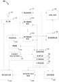
Fig. 6 illustrates a UT 602 in communication with a SNP 604 via a satellite 606 in a non-geosynchronous satellite communication system 600 (e.g., a LEO satellite communication system), such as for data, voice, video, or other communication. The UT 602, SNP 604, and satellite 606 may correspond to, for example, UT400, SNP200, and satellite 300 of fig. 1, respectively.
The SNP 604 includes a Network Access Controller (NAC)612, each of which interfaces with one or more Radio Frequency (RF) subsystems 614 for communicating with the UT 602 and other UTs (not shown) via a satellite 606 (or some other satellite, not shown). The SNP 604 also includes a Core Network Control Plane (CNCP)616 and a Core Network User Plane (CNUP)618 for communicating with a network 620 or other similar functionality (e.g., control and user plane functionality for other types of networks). Network 620 may represent, for example, one or more of a core network (e.g., 3G, 4G, 5G, etc.), an intranet, or the internet.
The present disclosure relates in some aspects to controlling duty cycles of transmissions by satellite 606 and other satellites (not shown) to control average transmit power per satellite. For example, to transmit 90% of the default transmit power of satellite 606, system 600 may be configured such that satellite 606 transmits at most 90% of the time. The duty cycle of the transmission may be gated within a relatively small time constant (e.g., much lower than the time constant used to calculate the average transmit power) to meet the average EPFD requirement defined by the ITU or other regulatory body. In some aspects, this technique can be used to meet a percentage limit, such as an ITU percentage limit. In some aspects, such techniques can be used to satisfy absolute limits, such as ITU absolute limits (e.g., depending on the time period used to calculate the maximum absolute EPFD).
In typical implementations, the SNP 604 determines (e.g., receives or generates) the duty cycle schedule 622. For example, NAC 612 may generate duty cycle schedules for all satellites under its control based on information received via network 620 (e.g., ephemeris information and regulatory limits) and information received from the satellites (e.g., status and configuration information). As another example, NAC 612 may receive duty cycle schedules for its satellites via network 620 (e.g., from network entity 628).
In some implementations, the duty cycle schedule 622 used by the system 600 is defined a priori. For example, the controller 630 of the network entity 628 may generate the duty cycle schedule 622 and transmit the duty cycle schedule 622 during system startup and/or at other times to control the components of the system 600. In particular, the network entity 628 may send the duty cycle schedule 622 to the SNP 604 via the network 620 (e.g., a core network, an intranet, or the internet) or some other data transmission mechanism. For purposes of illustration, network entity 628 is shown as being external to network 620. However, network entity 628 can be part of network 620.
Other entities in the system may also determine the duty cycle schedule 622. For example, the satellite 606 may receive the duty cycle schedule 622 from the SNP 604 or generate a duty cycle schedule for itself based on duty cycle-related information received from the SNP 604. As another example, the UT 602 can receive the duty cycle schedule 622 from the SNP 604 via the satellite 606, or generate a duty cycle schedule for itself based on duty cycle-related information received from the satellite 606 and/or the SNP 604.
Fig. 7 illustrates an overview of a process 700 for determining a duty cycle schedule, in accordance with some aspects of the present disclosure. Process 700 may occur, at least in part, within processing circuitry (e.g., processing circuitry 1510 of fig. 15) that may be located within a SNP, a network entity, a satellite, a UT, or some other suitable device. In some embodiments, process 700 may be performed by at least one non-geostationary satellite SNP (e.g., SNP200 of fig. 1). In some embodiments, the process 700 represents operations performed at least in part by the controllers 122, 124, or 126 of fig. 1, the SNP controller 250 of fig. 2, the controller 340 of fig. 3, the control processor 420 of fig. 4, the controller 1008 of fig. 10, the controllers 1108 or 1116 of fig. 11, or the controllers 1208 or 1218 of fig. 12. Of course, in various aspects within the scope of the disclosure, process 700 may be implemented by any suitable device capable of supporting communication operations.
At block 702, a device (e.g., a SNP, a network entity, a satellite, or a UT) determines a regulatory limit for satellite operation. For example, the apparatus may receive an indication of ITU EPFD limits (or other regulatory limits) or retrieve such an indication from a memory device.
At block 704, the apparatus determines other parameters that affect the power radiated onto the earth by each satellite in the satellite system. As discussed in more detail below in connection with fig. 8, the parameters may include, for example, at least one of: satellite ephemeris information, default satellite transmit power (e.g., default maximum transmit power or some other default value), offered load (e.g., expected traffic load of the satellite over the area), satellite health, satellite failure, satellite beam state, satellite beam failure, current satellite position, satellite position drift, operational drift of at least one satellite component, operational bias of at least one satellite component, satellite beam orientation error, satellite amplifier gain variation over a set of amplifiers, satellite antenna gain variation over a set of antennas, or directivity variation over a set of satellite antennas.
At block 706, the apparatus determines a duty cycle schedule for satellite transmissions based on the rule limits determined at block 702 and other parameters determined at block 704. As one example, this may involve determining, for a given region on earth at a given point in time: 1) satellites radiating to the region (e.g., determined from satellite ephemeris information and satellite position drift); 2) any satellite beam breaks; and 3) assuming the current effective transmit power of the satellites in the system radiating to the area at that time, the EPFD that will radiate onto the earth's surface (e.g., taking into account at least one of: default transmit power for each satellite, offered load for each satellite, operational bias, or other bias). If the determined EPFD exceeds the allowable limit, the duty cycle of the transmissions of one or more applicable satellites may be reduced to reduce the average transmit power from the applicable satellites.
As discussed in more detail below in connection with fig. 8, an overall duty cycle schedule can thus be defined that specifies, for each satellite, a duty cycle to be used at a specified point in time along the satellite's orbit (i.e., corresponding to different positions of the satellite along its respective orbital path). Since conditions may vary as a satellite traverses its orbit (e.g., there may be overlapping coverage from different satellites in different areas) or may change over time (e.g., a satellite beam may fail or operating conditions may change), different duty cycles may be defined for a given satellite over time. Also, since some satellites may employ multiple beams, a duty cycle may be defined for each beam of a given satellite.
At optional block 708, the apparatus may transmit the duty cycle schedule to a component of the satellite system. For example, the network entity may transmit the duty cycle schedule to one or more SNPs in the satellite system. As another example, the SNP may send a duty cycle schedule to each satellite served by the SNP. As yet another example, the SNP may send a duty cycle schedule to each UT served by the SNP.
In view of the above, several examples of factors that may be considered for determining the duty cycle of a satellite transmission will now be described in more detail. For purposes of explanation, the following describes a scenario in which the duty cycle is determined on a location basis (e.g., on a per latitude and longitude basis), however, it should be understood that in other scenarios the duty cycle may be determined on some other suitable basis (e.g., other geographical boundaries).
If the orbit of the satellite is determined, the duty cycle to be used at each location (e.g., latitude and longitude) covered by the signal can be determined. On a per-location basis, the maximum power and the percentage power required to meet regulatory limits are calculated. Thus, when the satellites are in coverage at a particular location on earth, the transmit power of each satellite can be controlled by using a duty cycle (and optionally by using other amplifier-based control techniques) to meet the power calculated for the particular location (e.g., latitude and longitude). Thus, an overall schedule can be created indicating the duty cycles to be used at different locations of each satellite corresponding to different locations (e.g., latitudes and longitudes) of the satellite coverage area as each satellite moves.
If the satellite generates multiple beams, a schedule can be created for each beam if the beam pattern is deterministic. For a given beam, the schedule indicates duty cycles to be used at different locations of the satellite corresponding to different locations (e.g., latitudes and longitudes) of the beam coverage area as the satellite moves.
In fact, satellite conditions may change over time. For example, a satellite may fail, the position accuracy of the satellite may drift over time, or components of the satellite may experience operational drift (e.g., the power transmitted by an amplifier at a given set point may change over time). Thus, to provide optimal transmit power, the duty cycles used by the satellites in the system may also be determined on a dynamic basis (e.g., periodically or aperiodically) based on these and/or other satellite conditions. Such dynamic duty cycle management may be performed by the SNP and/or other suitable system components.
With respect to satellite failure scenarios, at some point in time, more than one satellite may radiate power to the same region on earth. The initial duty cycle schedule may thus specify the duty cycle to be used by each satellite to ensure that the satellites collectively meet regulatory restrictions (e.g., ITU restrictions). In the event of a failure of one of the satellites (e.g., the interfering satellite), the transmit power of the satellite serving the area may increase (the remaining operational satellites still operate together within regulatory limits). In the event that multiple satellites serve the area and the interfering satellite fails, the transmit power of each serving satellite may be increased (the remaining operating satellites still operate together within regulatory limits). Thus, upon detection of a satellite (or beam) failure, the duty cycle of another satellite (or beam) may be changed.
With respect to satellite drift scenarios, the orbit of the satellite may not be constant over time (position drift) or the operation of the satellite components may change over time (e.g., as the electronic components age). These conditions may affect the amount of power radiated by a satellite (e.g., a satellite serving the area or a satellite interfering with the area) over a given area on earth. Thus, if any of these conditions are detected, the duty cycle of one or more satellites may be reduced to ensure regulatory limits are met, or the duty cycle of one or more satellites may be increased to ensure that each satellite transmits at an optimal power level. In some embodiments, these conditions (e.g., drift, beam orientation error, etc.) are detected by the UT and/or SNP. In some implementations, the satellite may report one or more of these conditions. For example, the satellite may report its location information (e.g., GPS coordinates) or attitude to the SNP.
Moreover, there may be variations in operating conditions between components of a given satellite or between components of different satellites. For example, the amplifier gain may vary across the set of amplifiers. As another example, the antenna gain may vary across the set of antennas. In addition, the directivity of the antenna may deviate from the ideal. However, assuming all of these components are highly calibrated, an a priori schedule may be developed (e.g., estimated). Thus, more static changes such as those affecting satellite radiated power may also be addressed by adjusting the duty cycle schedule.
In some embodiments, the definition of the duty cycle may be governed by an inner control loop and an outer control loop. As one example, the inner control loop may be based on a priori calculations for power radiated at different locations (e.g., latitude and longitude). The outer control loop may be based on tracking of satellite faults, satellite drift, changes in operating conditions, satellite states (e.g., satellite health), satellite configuration, or other factors that affect the power radiated on the earth's surface over time.
An example of a process 800 that may be used to calculate a duty cycle based on the above factors will now be described with reference to fig. 8. It should be understood that other algorithms may be used. Process 800 may occur, at least in part, within processing circuitry (e.g., processing circuitry 1510 of fig. 15) that may be located within a SNP, a network entity, a satellite, a UT, or some other suitable device. In some embodiments, process 800 may be performed by at least one non-geostationary satellite SNP (e.g., SNP200 of fig. 1). In some embodiments, the process 800 represents operations performed at least in part by the controllers 122, 124, or 126 of fig. 1, the SNP controller 250 of fig. 2, the controller 340 of fig. 3, the control processor 420 of fig. 4, the controller 1008 of fig. 10, the controllers 1108 or 1116 of fig. 11, or the controllers 1208 or 1218 of fig. 12. Of course, in various aspects within the scope of the disclosure, process 800 may be implemented by any suitable device capable of supporting communication operations.
At block 804, the apparatus determines information about the configuration of each satellite that may radiate onto the specified area. For example, the device may obtain ephemeris information for a constellation of satellites to identify the satellites (and, if applicable, particular beams of the satellites) expected to radiate onto the area, determine when the satellites/beams are expected to radiate onto the area, and determine whether multiple satellites/beams will radiate onto the area simultaneously. As another example, the apparatus may obtain information indicating a default transmit power that a particular satellite (e.g., for a particular beam) will use when radiating to the area.
At block 806, the apparatus determines the status of each satellite and/or beam that may be radiating onto the designated area. As one example, the satellite state may relate to a health of the satellite (e.g., satellite failure, satellite beam state, satellite beam failure). As described above, the status (e.g., failure) of a particular satellite or satellite beam may be considered when setting the transmit power or duty cycle for another satellite or satellite beam. As another example, the satellite states may relate to positions of satellites (e.g., current satellite positions or satellite position drifts). For example, this information can be used to fine tune the timing of transmit power or duty cycle adjustments to the satellites or satellite beams, as any deviation from the position indicated by the ephemeris information can be taken into account based on the actual satellite position and/or drift. As yet another example, the satellite states may relate to deviations in operation of a particular satellite (e.g., operational drift of at least one satellite component, operational deviation of at least one satellite component, and satellite beam orientation error). Here, manufacturing variations from the nominal characteristic values of the components and/or variations in the characteristics over time may affect the amount of energy actually radiated by the satellite (or satellite beam) over a given area. The timing of the transmit power or duty cycle adjustments to the satellites or satellite beams can be fine tuned to account for these differences. As yet another example, the satellite states may relate to differences between satellite components (e.g., satellite amplifier gain changes over a set of amplifiers, satellite antenna gain changes over a set of antennas, or directivity changes over a set of satellite antennas). In this case, differences between components (e.g., components that are to collectively generate a beam) may affect the amount of energy that a satellite (or satellite beam) actually radiates over a given area. The timing of the transmit power or duty cycle adjustments to the satellites or satellite beams can also be fine tuned to account for these differences. As another example, the satellite state may relate to a provided load for the satellite. In this case, by considering the expected load on the area of each satellite of a set of satellites (e.g., the satellites that may serve the area), the transmit power or duty cycle of each satellite may be adjusted to optimize the transmission of those satellites.
At block 808, the apparatus calculates a Cumulative Distribution Function (CDF) for the region. For example, at a given site on earth, the CDF can be calculated based on the energy (or power) and regulatory limits that can be sent to that site. The CDF may thus be calculated based on the absolute regulatory limits and/or the percentage regulatory limits and knowledge of the satellite constellation (e.g., where each satellite will transmit over time and at the transmit power determined at blocks 804 and 806). Thus, the CDF may indicate whether and to what extent the EPFD of the satellite of the constellation radiating to the region exceeds one of the regulatory limits. As described below, if regulatory limits are to be exceeded due to the transmit power currently specified for the satellites, the transmit duty cycle used by each satellite may be adjusted (reduced) to ensure that the regulatory limits are not exceeded.
To this end, at block 810, the apparatus calculates a maximum transmit power for each satellite and/or each beam of each satellite based on the CDF calculated at block 808. For example, the device may calculate (e.g., estimate) the maximum power that a particular satellite is allowed to radiate to a given area. Here, the limits of all satellites contributing to the site's power are calculated-including the serving satellite and any satellites that may cause interference.
At block 812, the apparatus determines a duty cycle for transmission over the region based on the maximum transmit power calculated at block 810. As discussed herein, the duty cycle is set to control the average transmit power radiated by a given satellite.
At optional block 814, the apparatus may control one or more amplifier parameters in conjunction with determining the duty cycle at block 812. For example, if a decrease in transmit power relative to a default transmit power is indicated, the reduced duty cycle may be selected in conjunction with a change in one or more of: changing the gain of the amplifier, changing the set point of the amplifier, or changing the number of amplifier stages used in the RF chain.
By performing the operations of blocks 802-814 for all regions on earth that a given satellite may cover, a schedule can be generated for the satellite specifying a duty cycle to be used in each region (e.g., corresponding to a desired reduction to a default satellite transmit power) to ensure regulatory restrictions are met. Similar schedules can be generated for all satellites in the satellite constellation.
Referring again to fig. 6, duty cycle schedule 622 is used to control the transmission of a composite transmit signal (e.g., one or more beams) from the satellite to all UTs within the satellite's coverage area. More generally, duty cycle schedule 622 can be used to control the transmission of composite transmit signals from all satellites in a constellation of satellites to all UTs within a satellite coverage area.
Various entities may initiate the transmission of the set duty cycle in different embodiments. For example, the SNP 604, the satellite 606, or the UT 602 may initiate transmission based on the duty cycle schedule 622, invoking transmission of the set duty cycle of the satellite 606 directly or indirectly.
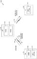
In some implementations, the SNP 604 (e.g., NAC 612) uses a duty cycle schedule 622 to control transmissions by the RF subsystem 614. In this case, designated RF subsystem 614 sends transmission 624 to satellite 606 via the forward feeder link based on duty cycle schedule 622. The satellite 606 (e.g., a so-called "bent-tube" satellite) can then relay corresponding transmissions 626 to the UT 602 via the forward service link based on the duty cycle schedule 622. Thus, in these embodiments, the duty cycle set transmission by the satellite 606 (e.g., the transmission 626 on the forward service link) is initiated indirectly by the duty cycle transmission by the SNP 604.
In some implementations, the SNP 604 (e.g., NAC 612) sends the duty cycle schedule 622 to a satellite (e.g., satellite 606) in the system 600. In this case, the satellite 606 can transmit transmissions 626 to the UTs 602 via the forward service links based on the duty cycle schedule 622. Alternatively, the satellite 606 may send the transmission 624 to the SNP 604 via the return feeder link based on the duty cycle schedule 622. In the latter case, the transmission 624 is received via the respective RF subsystem 614 and forwarded to the controlling NAC 612. Thus, in these embodiments, satellite 606 directly initiates the transmission of the set duty cycle by satellite 606.
In some implementations, the SNP 604 (e.g., NAC 612) sends a duty cycle schedule 622 to a UT (e.g., UT 602) in the system 600. In this case, the UT 602 can send a transmission 626 to the satellite 606 via the return service link based on the duty cycle schedule 622. Satellite 606 (e.g., a so-called "bent pipe" satellite) may then relay a corresponding transmission 624 to SNP 604 via a return feeder link based on duty cycle schedule 622. Thus, in these embodiments, the duty cycle set transmission by the satellite 606 (e.g., the transmission 624 on the return feeder link) is initiated indirectly by the duty cycle transmission by the UT 602. The transmission 624 is received via the corresponding RF subsystem 614 and forwarded to the controlling NAC 612.
Fig. 9 illustrates an overview of a process 900 for transmitting signals based on duty cycle scheduling in accordance with some aspects of the disclosure. Process 900 may be performed, at least in part, within processing circuitry (e.g., processing circuitry 1310 of fig. 13) that may be located within a SNP, a satellite, a UT, or some other suitable device. In some embodiments, process 900 may be performed by at least one non-geostationary satellite SNP (e.g., SNP200 of fig. 1). In some embodiments, the process 900 represents operations performed at least in part by the controllers 122, 124, or 126 of fig. 1, the SNP controller 250 and subsystems 210 and 220 of fig. 2, the controller 340 and repeaters 310 or 320 of fig. 3, the control processor 420 and transmit assembly of fig. 4, the controller 1008 and digital/RF subsystem 1010 of fig. 10, the controller 1108 or 1116 and digital/ RF subsystem 1110 or 1114 of fig. 11, or the controller 1208 or 1218 and digital/RF subsystem 1210 or repeater 1212 of fig. 12. Of course, in various aspects within the scope of the disclosure, process 900 may be implemented by any suitable device capable of supporting communication operations.
At block 902, a device (e.g., a SNP, a satellite, or a UT) determines a duty cycle schedule for satellite transmission. For example, the apparatus may receive or define a duty cycle schedule as described herein (e.g., as discussed above in connection with fig. 7 and 8).
At block 904, the apparatus determines other parameters that affect the power radiated onto the earth by each satellite in the satellite system. These parameters may include, for example, a specified gain of the amplifier, a specified set point of the amplifier, or a specified amplifier stage number for the RF chain driving the antenna.
At block 906, the apparatus transmits signals to or from the satellite according to the duty cycle schedule determined at block 902 and other parameters determined at block 904. For example, if the apparatus is a satellite, the operations of block 906 may involve sending a signal to the UT, where the transmit power is a function of a duty cycle specified for transmission of the satellite on the forward service link, a specified gain of an amplifier of the satellite, a specified set point of the amplifier, and a specified amplifier stage number specified for an RF chain driving the antenna. As another example, if the apparatus is a SNP, the operations of block 906 may involve transmitting a signal to a satellite, where the transmit power is a function of the RF amplifier setting of the SNP and a duty cycle specified for transmission of the satellite on the forward service link.
As described above, different entities may initiate the transmission of the set duty cycle in different embodiments. Fig. 10-12 illustrate three exemplary embodiments of this aspect.
Fig. 10 shows an example of a satellite communication system 1000 in which a SNP 1004 initiates transmission of a set duty cycle. The UT 1002 communicates with the SNP 1004 via a satellite 1006. The SNP 1004 includes a controller 1008 that determines duty cycle schedules for satellite communications in the system 1000. The SNP 1004 also includes a digital/RF subsystem 1010 (e.g., transmitter and receiver components) for communicating with the satellite 1006. The satellite 1006 includes a transponder 1012 (e.g., a forward transponder and a return transponder) for communicating with the SNP 1004 and the UT 1002. The UT 1002 includes a digital/RF subsystem 1014 (e.g., transmitter and receiver components) for communicating with the satellite 1006.
When the SNP 1004 has data to send to the UT 1002, the controller 1008 causes the digital/RF subsystem 1010 to send a data transmission 1020 with a set duty cycle to the satellite 1006. Typically, the duty cycle set transmission 1020 is a waveform that includes overhead, signaling, and data. The transmission of the waveform is based on a duty cycle schedule (e.g., duty cycle schedule 622 of fig. 6) determined by controller 1008. In other words, the SNP 1004 may format signals sent to the satellite 1006 for transmission to the UT 1002 according to a duty cycle currently defined for transmission by the satellite 1006. For example, if subframe-based communication is used for transmission 1020 on the forward feeder link, only a percentage (e.g., X%) of the defined subframes may be used for transmission 1020 from the SNP 1004 to the satellite 1006 (i.e., using transmit duty cycle control within the subframes).
A transponder 1012 of a satellite 1006 (e.g., a so-called "bent-tube" satellite) can relay a waveform received from the SNP 1004 via a forward feeder link to the UT 1002 via a forward service link. Since the received transmission 1020 is duty-cycled, the satellite 1006 will send a duty-cycled data transmission 1022 to the UT 1002. Thus, the duty cycle of the transmission 1022 will be scheduled based on the duty cycle used by the SNP 1004. As a result, the average transmit power of the satellite 1006 as received by the digital RF subsystem 1014 of the UT 1002 will be limited based on the duty cycle schedule. For example, if the satellite 1006 transmits a waveform to the UT 1002 in only X% of the subframes used for the forward service link, the average transmit power of the transmission 1022 may be up to X% of the default transmit power of the subframes on the forward service link.
The SNP 1004 may use control signaling (e.g., over a control channel) to inform each UT (e.g., including UT 1002) that it serves which subframes are to be used for transmitting information to the UT and where in each subframe the data is. Thus, in some aspects, the invocation and/or use of set duty cycles may be transparent to the UTs and satellites in system 1000.
It should be understood that the disclosed duty cycle techniques may be used for any form of time boundary. For example, the duty cycle may be applied to a frame, a subframe, a portion of a subframe, a superframe, a slot, and so forth.
Fig. 11 illustrates an example of a satellite communication system 1100 in which a UT 1102 initiates transmission of a set duty cycle. That is, the set duty cycle may be employed on the return link from the UT 1102 to the SNP 1104 via the satellite 1106. For example, if the return link uses a time limit (e.g., a Time Division Multiple Access (TDMA) waveform), a set duty cycle may be used herein, particularly if a percentage power limit applies.
The SNP 1104 includes a controller 1108 that provides duty cycle information for satellite communications in the system 1100. The SNP 1104 also includes a digital/RF subsystem 1110 (e.g., transmitter and receiver components) for communicating with the satellite 1106. The satellite 1106 includes transponders 1112 (e.g., forward transponders and return transponders) for communicating with the SNP 1104 and the UT 1102. The UT 1102 includes a digital/RF subsystem 1114 (e.g., transmitter and receiver components) for communicating with the satellite 1106. The UT 1102 also includes a controller 1116 that determines a duty cycle schedule for satellite communications in the system 1100.
In some embodiments, the controller 1116 of the UT 1102 obtains duty cycle information from the controller 1108 of the SNP 1104. For example, the controller 1108 may transmit the duty cycle information 1120 to the satellite 1106 via a forward feeder link, whereby the satellite 1106 transmits corresponding (e.g., forwarded) duty cycle information 1122 to the UT 1102 via a forward service link. The duty cycle information may include, for example, a duty cycle schedule to be used by the controller 1116 for return link transmissions, or information used by the controller 1116 to determine a duty cycle schedule to be used for return link transmissions.
Thus, the UT 1102 can use the set duty cycle on transmissions to the satellite 1106 over the return service link, and the satellite 1106 forwards the corresponding set duty cycle transmissions to the SNP 1104 over the return feeder link. For example, when the UT 1102 has data to send to the SNP 1104, the controller 1116 causes the digital/RF subsystem 1114 to send a duty cycle set data transmission 1124 to the satellite 1106. The transmission 1124 with the duty cycle set may be a waveform that includes overhead, signaling, and data. The transmission of the waveform is based on a duty cycle schedule (e.g., duty cycle schedule 622 of fig. 6) determined by controller 1116. For example, transmission 1124 may use X% of each available subframe on the return serving link.
A repeater 1112 of a satellite 1106 (e.g., a so-called "bent-tube" satellite) may relay waveforms received from the UT 1102 over a return service link to the SNP 1104 via a return feeder link. Since the received transmission 1124 is duty-cycled, the satellite 1106 will send a duty-cycled data transmission 1126 to the SNP 1104. Thus, the duty cycle of the transmission 1126 will be scheduled based on the duty cycle used by the UT 1102. As a result, the average transmit power of the satellites 1106 received by the digital RF subsystem 1110 of the SNP 1104 will be limited based on this duty cycle schedule. For example, if the satellite 1106 sends a waveform to the SNP 1104 in only X% of the subframe for the return feeder link, the average transmit power of the transmission 1126 may be up to X% of the default transmit power of the subframe on the return service link.
The UT 1102 may use control signaling (e.g., over a control channel) to inform each SNP (e.g., including SNP 1104) that it serves which subframes are to be used for transmitting information to the SNP and where in each subframe the data is. Thus, in some aspects, the invocation and/or use of the set duty cycle may be transparent to SNPs and satellites in the system 1000.
Fig. 12 shows an example of a satellite communications system 1200 in which a satellite 1206 initiates a transmission with a set duty cycle. That is, the satellite 1206 may control duty cycle control for satellite transmissions (e.g., by transmitting in X% of a subframe), thereby controlling the average transmit power of the satellite 1206 when the satellite 1206 transmits to UTs and/or SNPs.
In fig. 12, the UT 1202 communicates with the SNP 1204 via a satellite 1206. The SNP 1204 includes a controller 1208 that provides duty cycle information for satellite communications in the system 1200. The SNP 1204 also includes a digital/RF subsystem 1210 (e.g., transmitter and receiver components) for communicating with the satellite 1202. The satellite 1206 includes a transponder 1212 (e.g., a forward transponder and a return transponder) for communicating with the SNP 1204 and the UT 1202. The satellites 1206 also include a controller 1118 that determines a duty cycle schedule for satellite communications in the system 1100. The UT 1202 includes a digital/RF subsystem 1214 (e.g., transmitter and receiver components) for communicating with the satellite 1206.
In this case, the satellite 1206 will receive and/or generate a duty cycle schedule (e.g., as discussed herein). In some embodiments, the controller 1218 of the satellite 1206 obtains duty cycle information from the controller 1208 of the SNP 1204. For example, the controller 1208 may transmit the duty cycle information 1220 to the satellite 1206 via a forward feeder link. The duty cycle information may include, for example, duty cycle schedules to be used by controller 1218 for forward and/or return link transmissions or information that controller 1218 uses to determine duty cycle schedules to be used for forward and/or return link transmissions.
When the satellite 1206 receives data to be transmitted, the satellite can packetize the data and transmit the packetized data according to a duty cycle schedule. The satellite 1206 can forward data to the UT 1202 or the SNP 1204 based on the duty cycle schedule. Each of these scenarios will be discussed in turn.
When the satellite 1206 receives data from the SNP 1204 to be transmitted to the UT 1202, the controller 1218 causes the transponder 1212 to send a duty-cycle-set data transmission 1222 to the UT 1202. The duty cycle set transmission 1222 may be a waveform that includes overhead, signaling, and data. The transmission of the waveform is based on a duty cycle schedule (e.g., duty cycle schedule 622 of fig. 6) determined by controller 1218. As a result, the average transmit power of the satellite 1206 received by the digital RF subsystem 1214 of the UT 1202 is limited based on this duty cycle schedule. For example, if the satellite 1206 transmits a waveform to the UT 1202 in only X% of the subframes used for the forward service link, the average transmit power of the transmission 1222 can be up to X% of the default transmit power of the subframes on the forward service link.
When the satellite 1206 receives data from the UT 1202 to send to the SNP 1204, the controller 1218 causes the transponder 1212 to send a duty-cycle-set data transmission 1226 to the SNP 1204. The duty cycle set transmission 1226 may be a waveform that includes overhead, signaling, and data. The transmission of the waveform is based on a duty cycle schedule (e.g., duty cycle schedule 622 of fig. 6) determined by controller 1218. As a result, the average transmit power of the satellite 1206 received by the digital RF subsystem 1210 of the SNP 1204 will be limited based on this duty cycle schedule. For example, if the satellite 1206 sends a waveform to the SNP 1204 in only X% of the subframes used for the return feeder link, the average transmit power of the transmission 1226 may be at most X% of the default transmit power of the subframes on the return feeder link.
The satellite 1206 can use control signaling (e.g., over a control channel) to inform each of its associated UTs and/or SNPs (e.g., including UT 1202 and/or SNP 1204) which subframes are to be used to transmit information to the UTs and/or SNPs and where in each subframe the data is. Thus, in some aspects, invocation and/or use of duty cycle control may be transparent to UTs and SNPs in system 1000.
Exemplary devices
Fig. 13 illustrates a block diagram of an exemplary hardware implementation of an apparatus 1300 configured to communicate in accordance with one or more aspects of the present disclosure. For example, apparatus 1300 may be embodied or implemented within a SNP, a satellite, a UT, or some other type of device that supports satellite communications. In various embodiments, apparatus 1300 may be embodied or implemented within a gateway, a ground station, a vehicle component, or any other electronic device having circuitry.
The apparatus 1300 includes a communication interface (e.g., at least one transceiver) 1302, a storage medium 1304, a user interface 1306, a memory device (e.g., memory circuitry) 1308, and processing circuitry (e.g., at least one processor) 1310. In various implementations, the user interface 1306 may include one or more of the following: a keypad, a display, a speaker, a microphone, a touch screen display, some other circuitry for receiving input from a user or sending transmissions to a user.
These components can be coupled to and/or placed in electrical communication with each other via a signaling bus or other suitable components, represented generally by the connecting lines in fig. 13. The signaling bus may include any number of interconnecting buses and bridges depending on the specific application of the processing circuit 1310 and the overall design constraints. The signaling bus links the various circuits together such that each of the communication interface 1302, the storage medium 1304, the user interface 1306, and the memory device 1308 is coupled to and/or in electrical communication with the processing circuit 1310. The signaling bus may also link various other circuits (not shown), such as timing sources, peripherals, voltage regulators, and power management circuits, which are well known in the art, and therefore, will not be described again.
The communication interface 1302 may provide a means for communicating with other devices over a transmission medium. In some implementations, the communication interface 1302 includes circuitry and/or programming adapted to facilitate two-way communication of information with respect to one or more communication devices in a network. In some implementations, the communication interface 1302 is adapted to facilitate wireless communication for the apparatus 1300. In these embodiments, the communication interface 1302 may be coupled to one or more antennas 1312 shown in fig. 13 for wireless communication within a wireless communication system. The communication interface 1302 can be configured with one or more separate receivers and/or transmitters, as well as one or more transceivers. In the depicted example, communication interface 1302 includes a transmitter 1314 and a receiver 1316. The communication interface 1302 serves as one example of a means for receiving and/or a means for transmitting.
By way of example, and not limitation, storage media 1304 may include magnetic storage devices (e.g., hard disks, floppy disks, magnetic strips), optical disks (e.g., Compact Disks (CDs) or Digital Versatile Disks (DVDs)), smart cards, flash memory devices (e.g., cards, stick or key drives), Random Access Memory (RAM), Read Only Memory (ROM), programmable ROM (prom), erasable prom (eprom), electrically erasable prom (eeprom), registers, removable disks, and any other suitable medium for storing software and/or instructions that may be accessed and read by a computer. The storage medium 1304 may be embodied in an article of manufacture (e.g., a computer program product). By way of example, a computer program product may include a computer-readable medium in packaging material. In view of the above, in some implementations, the storage medium 1304 may be a non-transitory (e.g., tangible) storage medium.
The storage medium 1304 may be coupled to the processing circuit 1310 such that the processing circuit 1310 is capable of reading information from the storage medium 1304 and writing information to the storage medium 1304. That is, the storage medium 1304 can be coupled to the processing circuit 1310 such that the storage medium 1304 is at least accessible by the processing circuit 1310, including examples in which at least one storage medium is integrated into the processing circuit 1310 and/or examples in which at least one storage medium is separate from the processing circuit 1310 (e.g., resident within the apparatus 1300, external to the device 1300, distributed among multiple entities, etc.).
The storage medium 1304 stores a program that, when executed by the processing circuit 1310, causes the processing circuit 1310 to perform one or more of the various functions and/or processing operations described herein. For example, the storage medium 1304 may include operations configured to regulate operations at one or more hardware blocks of the processing circuit 1310, as well as operations configured to utilize the communication interface 1302 for wireless communication using their respective communication protocols.
The processing circuit 1310 is generally adapted to process, including executing, such programs stored on the storage medium 1304. As used herein, the term "code" or "program" is to be broadly interpreted to include, but is not limited to, instructions, instruction sets, data, code segments, program code, programs, programming, subroutines, software modules, applications, software packages, routines, subroutines, objects, executables, threads of execution, procedures, functions, and the like, whether referred to as software, firmware, middleware, microcode, hardware description language, or other terminology.
The processing circuitry 1310 is arranged to obtain, process and/or transmit data, control data access and storage, issue commands and control other desired operations. In at least one example, the processing circuitry 1310 may include circuitry configured to implement a desired program provided by a suitable medium. For example, the processing circuit 1310 may be implemented as one or more processors, one or more controllers, and/or other structures configured to execute executable programs. Examples of processing circuit 1310 may include a general purpose processor, a Digital Signal Processor (DSP), an Application Specific Integrated Circuit (ASIC), a Field Programmable Gate Array (FPGA) or other programmable logic component, discrete gate or transistor logic, discrete hardware components, or any combination thereof designed to perform the functions described herein. A general purpose processor may include a microprocessor, as well as any conventional processor, controller, microcontroller, or state machine. The processing circuit 1310 may also be implemented as a combination of computing components, such as a combination of a DSP and a microprocessor, a plurality of microprocessors, one or more microprocessors in conjunction with a DSP core, an ASIC and a microprocessor, or any other number of different configurations. These examples of processing circuit 1310 are for illustration, and other suitable configurations are also contemplated as being within the scope of the present disclosure.
In accordance with one or more aspects of the present disclosure, the processing circuit 1310 may be adapted to perform any or all of the features, processes, functions, operations, and/or routines of any or all of the apparatuses described herein. For example, the processing circuit 1310 may be configured to perform any of the steps, functions, and/or processes described with respect to fig. 9 and 14. As used herein, the term "adapted to" with respect to the processing circuit 1310 may refer to the processing circuit 1310 being configured, employed, implemented and/or programmed to perform one or more of the specific processes, functions, operations and/or routines in accordance with the various features described herein.
The processing circuit 1310 may be a special-purpose processor, such as an Application Specific Integrated Circuit (ASIC), that functions as a means for performing any of the operations described in conjunction with fig. 9 and 14 (e.g., a structure for performing any of the operations described in conjunction with fig. 9 and 14). Processing circuit 1310 serves as one example of a means for transmitting and/or a means for receiving. In some implementations, the processing circuit 1310 may provide, at least in part, the functionality of at least one of: the controllers 122, 124, or 126 of FIG. 1, the SNP controller 250 of FIG. 2, the controller 340 of FIG. 3, the control processor 420 of FIG. 4, the controller 1008 of FIG. 10, the controllers 1108 or 1116 of FIG. 11, or the controllers 1208 or 1218 of FIG. 12.
According to at least one example of the apparatus 1300, the processing circuit 1310 may include one or more of a circuit/module 1320 for receiving duty cycle schedules or a circuit/module 1322 for transmitting signals.
The circuitry/module 1320 for receiving duty cycle schedules may include circuitry and/or programming (e.g., code 1324 stored on the storage medium 1304 for receiving duty cycle schedules) adapted to perform several functions related to, for example, receiving duty cycle schedules (e.g., indications of schedules) for satellite transmissions from another apparatus. Initially, the circuit/module for receiving duty cycle schedule 1320 obtains the received information. For example, the circuitry/module 1320 for receiving the duty cycle schedule may obtain the information from a component of the apparatus 1300, such as the communication interface 1302 (e.g., a digital subsystem or an RF subsystem), the memory device 1308, or some other component, or directly from a device that generated the information (e.g., a network entity or a SNP). In some implementations, the circuit/module for receiving duty cycle schedules 1320 identifies a memory location of a value in the memory device 1308 and invokes a read of that location. In some implementations, the circuit/module for receiving duty cycle schedule 1320 processes (e.g., decodes) the received information to extract an indication of the duty cycle schedule. The circuit/module for receiving duty cycle scheduling 1320 outputs the received information (e.g., stores the indication in the memory device 1308 or sends the information to another component of the apparatus 1300). In some implementations, the communication interface 1302 includes a circuit/module 1320 to receive the duty cycle schedule and/or code 1324 to receive the duty cycle schedule.
The circuitry/module 1322 for transmitting signals may include circuitry and/or programming (e.g., code 1326 stored on the storage medium 1304 for transmitting signals) adapted to perform several functions related to transmitting signals (e.g., including information) to another apparatus, e.g., according to a duty cycle schedule. Initially, circuitry/module 1322 for transmitting signals obtains information to be transmitted (e.g., from memory device 1308 or some other component) and a duty cycle schedule (e.g., from circuitry/module 1320 for receiving the duty cycle schedule). In some embodiments, the information is sent based on a duty cycle schedule (e.g., the transmission is duty-cycled). In some embodiments, the information to be transmitted may include a duty cycle schedule (e.g., an indication of the schedule). The circuitry/module 1322 for sending the signal may format the information for transmission (e.g., in a message, according to a protocol, etc.). The circuitry/module 1322 for transmitting signals then causes information to be transmitted via a wireless communication medium (e.g., via satellite signal transmission) according to the duty cycle schedule. To this end, circuitry/module 1322 for sending signals may send information to communication interface 1302 (e.g., a digital subsystem or an RF subsystem) or some other component for transmission. In some implementations, the communication interface 1302 includes circuitry/modules 1322 for transmitting signals and/or code 1326 for transmitting signals.
As described above, the program stored by the storage medium 1304, when executed by the processing circuit 1310, causes the processing circuit 1310 to perform one or more of the various functions and/or processing operations described herein. For example, the program, when executed by the processing circuit 1310, may cause the processing circuit 1310 to perform various functions, steps and/or processes described herein in various embodiments with respect to fig. 9 and 14. As shown in fig. 13, the storage medium 1304 may include one or more of code 1324 for receiving a duty cycle schedule or code 1326 for transmitting a signal.
Exemplary procedure
Fig. 14 illustrates a process 1400 for communication in accordance with some aspects of the disclosure. Process 1400 may be performed within processing circuitry (e.g., processing circuitry 1310 of fig. 13) that may be located within a SNP, a satellite, a UT, or some other suitable device. In some embodiments, process 1400 may be performed by at least one non-geostationary satellite SNP. In some implementations, process 1400 represents being performed, at least in part, by at least one of: the controllers 122, 124, or 126 of FIG. 1, the SNP controller 250 of FIG. 2, the controller 340 of FIG. 3, the control processor 420 of FIG. 4, the controller 1008 of FIG. 10, the controllers 1108 or 1116 of FIG. 11, or the controllers 1208 or 1218 of FIG. 12. Of course, in various aspects within the scope of the disclosure, process 1400 may be implemented by any suitable device capable of supporting communication operations.
At block 1402, a device (e.g., a SNP, a satellite, or a UT) receives a duty cycle schedule for satellite transmission. For example, the SNP may receive the schedule from a network entity, the satellite may receive the schedule from the SNP, or the UT may receive the schedule from the SNP.
In some aspects, the duty cycle schedule specifies a percentage of time elements defined according to a time boundary to be used for transmitting data. The time elements may include, for example, subframes, portions of subframes, frames, superframes, or slots.
In some aspects, the duty cycle schedule specifies a plurality of duty cycles to be used in a time period corresponding to one orbit, a portion of one orbit, or a plurality of orbits of at least one satellite. In some aspects, for each beam transmitted by at least one satellite, the duty cycle schedule specifies a plurality of duty cycles to be used in a time period corresponding to one orbit, a portion of one orbit, or multiple orbits of at least one satellite.
The duty cycle schedule may be based on various types of information. In some aspects, the duty cycle schedule is based on at least one limit on power radiated onto the area. In some aspects, the duty cycle schedule is based on location information for each of the at least one satellite. In some aspects, the duty cycle schedule is based on beam information for each of the at least one satellite. In some aspects, the duty cycle schedule is based on configuration information for each of the at least one satellite. In some aspects, the duty cycle schedule is based on state information of each of the at least one satellite.
At block 1404, the apparatus transmits the signal according to a duty cycle schedule. In some aspects, the transmission of the signal involves transmitting the signal to at least one satellite. For example, the SNP may transmit a signal to at least one satellite according to a duty cycle schedule. As another example, the UT can transmit signals to at least one satellite according to a duty cycle schedule. In some aspects, the transmission of the signal involves transmission of the signal by at least one satellite. For example, the satellite may schedule signals to the UTs or SNPs according to the duty cycles.
Exemplary devices
Fig. 15 illustrates a block diagram of an exemplary hardware implementation of another apparatus 1500 configured to communicate in accordance with one or more aspects of the present disclosure. For example, the apparatus 1500 may be embodied or implemented within a SNP, a network entity, a satellite, a UT, or some other type of device that supports satellite communications. In various embodiments, the apparatus 1500 may be embodied or realized within a gateway, a ground station, a vehicle component, or any other electronic device having circuitry.
The apparatus 1500 includes a communication interface (e.g., at least one transceiver) 1502, a storage medium 1504, a user interface 1506, a memory device 1508 (e.g., storing information related to duty cycle 1518), and a processing circuit (e.g., at least one processor) 1510. In various implementations, the user interface 1506 can include one or more of the following: a keypad, a display, a speaker, a microphone, a touch screen display of some other circuitry for receiving input from a user or sending output to a user. The communication interface 1502 may be coupled to one or more antennas 1512 and may include a transmitter 1514 and a receiver 1516. In general, the components of fig. 15 may be similar to the corresponding components of the apparatus 1300 of fig. 13.
In accordance with one or more aspects of the present disclosure, the processing circuit 1510 may be adapted to perform any or all of the features, processes, functions, operations, and/or routines of any or all of the apparatuses described herein. For example, the processing circuit 1510 may be configured to perform any of the steps, functions, and/or processes described with respect to fig. 7, 8, 9, and 16. As used herein, the term "adapted to" with respect to the processing circuit 1510 may refer to the processing circuit 1510 being configured, employed, implemented and/or programmed to perform one or more of the specific processes, functions, operations and/or routines in accordance with the various features described herein.
The processing circuit 1510 may be a special-purpose processor, such as an Application Specific Integrated Circuit (ASIC), that functions as a means for performing any of the operations described in conjunction with fig. 7, 8, 9, and 16 (e.g., a structure for performing any of the operations described in conjunction with fig. 7, 8, 9, and 16). Processing circuit 1510 serves as an example of a means for transmitting and/or a means for receiving. In various embodiments, the processing circuit 1510 may provide, at least in part, the functionality of at least one of: the controllers 122, 124, or 126 of FIG. 1, the SNP controller 250 of FIG. 2, the controller 340 of FIG. 3, the control processor 420 of FIG. 4, the controller 1008 of FIG. 10, the controllers 1108 or 1116 of FIG. 11, or the controllers 1208 or 1218 of FIG. 12.
According to at least one example of apparatus 1500, processing circuitry 1510 may include one or more of circuitry/module 1520 for determining at least one limit, circuitry/module 1522 for determining power to be radiated, circuitry/module 1524 for determining a duty cycle schedule, or circuitry/module 1526 for transmitting a signal.
The circuitry/module 1520 for determining at least one limit may comprise circuitry and/or programming (e.g., code 1528 stored on the storage medium 1504 for determining at least one limit) adapted to perform several functions related to, for example, determining at least one limit on the power radiated onto a given region. In some implementations, the circuitry/module 1520 to determine the at least one restriction obtains the information (e.g., from the memory device 1508 via the communication interface 1502 or from some other component of the apparatus 1500). Circuitry/module for determining at least one limit 1520 may then process this information to determine each limit (e.g., ITU limit) for a given region. Circuitry/module 1520 for determining at least one limit generates an indication of the determination and sends the indication to a component of apparatus 1500 (e.g., circuitry/module 1524 for determining a duty cycle, memory device 1508 or some other component).
The circuitry/module 1522 for determining the power to be radiated may include circuitry and/or programming (e.g., code 1530 stored on the storage medium 1504 for determining the power to be radiated) adapted to perform several functions related to, for example, determining the power to be radiated onto an area by a plurality of satellites. In some implementations, the circuitry/module 1522 for determining the power to be radiated obtains this information (e.g., from the memory device 1508 via the communication interface 1502 or from some other component of the apparatus 1500). In some implementations, the circuitry/module 1522 for determining the power to be radiated calculates this information (e.g., as discussed above in connection with fig. 7 and 8). In either case, the circuitry/module 1522 for determining the power to be radiated generates an indication of this determination (e.g., indicating the amount of power to be radiated onto the area by one or more satellites) and sends this indication to a component of the apparatus 1500 (e.g., the circuitry/module 1524 for determining the duty cycle, the memory device 1508, or some other component).
The circuitry/module 1524 for determining a duty cycle schedule may include circuitry and/or programming (e.g., code 1532 stored on the storage medium 1504 for determining a duty cycle schedule) adapted to perform several functions related to, for example, determining a duty cycle schedule for a satellite transmission. In some aspects, the determination of the duty cycle schedule may be based on at least one limit for at least one region (e.g., received from circuitry/module 1520 for determining the at least one limit). In some aspects, the determination of the duty cycle schedule may be based on the determined power for the at least one region (e.g., received from the circuit/module 1522 for determining the power to be radiated). Initially, the circuit/module 1524 for determining the duty cycle schedule obtains information for making the determination. For example, the circuitry/module 1524 for determining the duty cycle schedule may obtain this information from a component of the apparatus 1500 (e.g., the communication interface 1502 (e.g., a digital subsystem or RF subsystem), the memory device 1508, or some other component) or directly from the device that generated the information (e.g., as described above). In some implementations, the circuit/module 1524 for determining the duty cycle schedule identifies a memory location of the value in the memory device 1508 and invokes a read of that location. The circuit/module 1524 for determining the duty cycle schedule processes the obtained information to calculate the duty cycle schedule (e.g., as discussed above in connection with fig. 7 and 8). The circuit/module 1524 for determining a duty cycle schedule then outputs an indication of the duty cycle schedule (e.g., stores the indication in the memory device 1508, sends the indication to the communication interface 1502, or sends the indication to another component of the apparatus 1500).
The circuitry/module for transmitting signals 1526 may include circuitry and/or programming (e.g., code 1534 stored on the storage medium 1504 for transmitting signals) adapted to perform several functions related to, for example, transmitting signals (e.g., including information) to another apparatus according to a duty cycle schedule. Initially, the circuitry/module 1526 used to transmit the signal obtains the information to be transmitted (e.g., from the memory device 1508 or some other component). In some embodiments, the information is sent based on a duty cycle schedule (e.g., the transmission is duty-cycled). In some embodiments, the information to be transmitted may include a duty cycle schedule (e.g., an indication of the schedule). The circuitry/module 1526 for sending signals may format information for transmission (e.g., in a message according to a protocol, etc.). The circuitry/module 1526 for transmitting signals then causes the information to be transmitted via a communication medium (e.g., via satellite signaling or a network connection) according to the duty cycle schedule. To that end, circuitry/module 1526 for sending signals may send information to communication interface 1502 (e.g., a digital subsystem or an RF subsystem) or some other component for transmission. In some implementations, the communication interface 1502 includes circuitry/module 1526 and/or code 1534 for transmitting signals.
As described above, programs stored by the storage medium 1504, when executed by the processing circuit 1510, cause the processing circuit 1510 to perform one or more of the various functions and/or processing operations described herein. For example, the program, when executed by the processing circuit 1510, may cause the processing circuit 1510 to perform various functions, steps, and/or processes described herein in various embodiments with respect to fig. 6 and 16. As shown in fig. 15, storage medium 1504 may include one or more of code 1528 to determine at least one limit, code 1530 to determine a power to be radiated, code 1532 to determine a duty cycle schedule, or code 1534 to transmit a signal.
Exemplary procedure
Fig. 16 illustrates a process 1600 for communication in accordance with some aspects of the disclosure. Process 1600 may occur, at least in part, within processing circuitry (e.g., processing circuitry 1510 of fig. 15) that may be located within a SNP, a network entity, a satellite, a UT, or some other suitable device. In some embodiments, process 1600 may be performed by a SNP of at least one non-geostationary satellite. In some implementations, the process 1600 represents operations performed at least in part by at least one of: the controllers 122, 124, or 126 of FIG. 1, the SNP controller 250 of FIG. 2, the controller 340 of FIG. 3, the control processor 420 of FIG. 4, the controller 1008 of FIG. 10, the controllers 1108 or 1116 of FIG. 11, or the controllers 1208 or 1218 of FIG. 12. Of course, in various aspects within the scope of the disclosure, process 1600 may be implemented by any suitable device capable of supporting communication operations.
At block 1602, an apparatus (e.g., a SNP, a network entity, a satellite, or a UT) determines, for each of a plurality of regions, at least one limit on power radiated onto the region. In some aspects, the at least one limit may be at least one International Telecommunications Union (ITU) power limit.
At block 1604, the apparatus determines power to be radiated onto each of the areas by the plurality of satellites. For example, the apparatus may calculate the CDF as discussed herein.
In some aspects, the determination of power may be based on information regarding at least one configuration of each of the satellites. In some aspects, the at least one configuration comprises at least one of: satellite ephemeris information or default transmit power.
In some aspects, the determination of power is based on information about at least one state of each of the satellites. In some aspects, the at least one state comprises at least one of: a provided load, a satellite health, a satellite fault, a beam state, a beam fault, a current satellite position, a satellite position drift, an operational drift of at least one satellite component, an operational bias of at least one satellite component, a satellite beam orientation error, an amplifier gain change on a set of amplifiers, a satellite antenna gain change on a set of antennas, or a directivity change on a set of antennas.
At block 1606, the apparatus determines a duty cycle schedule for the satellite transmission based on the at least one limit for each region determined at block 1602 and the power for each region determined at block 1604. In some aspects, the duty cycle schedule specifies a percentage of time elements defined according to a time boundary to be used for transmitting data. In some aspects, the time element comprises: a subframe, a portion of a subframe, a frame, a superframe, or a slot.
In some aspects, the duty cycle schedule specifies a plurality of duty cycles to be used in a time period corresponding to one orbit, a portion of an orbit, or a plurality of orbits of at least one satellite. In some aspects, for each beam transmitted by at least one satellite, the duty cycle schedule specifies a plurality of duty cycles to be used in a time period corresponding to one orbit, a portion of an orbit, or a plurality of orbits of at least one satellite.
At block 1608, the apparatus transmits the signal according to the duty cycle schedule. In some embodiments, the SNP transmits signals to at least one of the satellites according to a duty cycle schedule. In some embodiments, one of the satellites transmits a signal according to a duty cycle schedule. In some implementations, the UT transmits signals to at least one of the satellites according to a duty cycle schedule.
In some aspects, the transmission of the signal involves transmitting the signal to at least one satellite. For example, the SNP may transmit a signal to at least one satellite according to a duty cycle schedule. As another example, the UT can transmit signals to at least one satellite according to a duty cycle schedule. In some aspects, the transmission of the signal includes transmission of the signal by at least one of the satellites. For example, the satellite may transmit signals to the UT or SNP according to a duty cycle schedule. In some aspects, the transmission of the signal includes a signal transmission by a network entity (e.g., the network entity sends a message including an indication of the duty cycle schedule to the SNP via a network connection).
Other aspects
Many aspects are described in terms of sequences of actions to be performed by, for example, elements of a computing device. It will be recognized that various actions described herein can be performed by specific circuits (e.g., a Central Processing Unit (CPU), a Graphics Processing Unit (GPU), a Digital Signal Processor (DSP), an Application Specific Integrated Circuit (ASIC), a Field Programmable Gate Array (FPGA) or various other types of general or special purpose processors or circuits), by program instructions being executed by one or more processors, or by a combination of both. Further, the sequences of actions described herein can be considered to be embodied entirely within any form of computer readable storage medium having stored therein a corresponding set of computer instructions that upon execution would cause an associated processor to perform the functions described herein. Thus, the various aspects of the disclosure may be embodied in many different forms, all of which are considered to be within the scope of the claimed subject matter. Additionally, for each aspect described herein, the respective form of any such aspect may be described herein as, for example, "logic configured to" perform the described action.
Those of skill in the art would understand that information and signals may be represented using any of a variety of different technologies and techniques. For example, data, instructions, commands, information, signals, bits, symbols, and chips that may be referenced throughout the above description may be represented by voltages, currents, electromagnetic waves, magnetic fields or particles, optical fields or particles, or any combination thereof,
furthermore, those of skill in the art will appreciate that the various illustrative logical blocks, modules, circuits, and algorithm steps described in connection with the aspects disclosed herein may be implemented as electronic hardware, computer software, or combinations of both. To clearly illustrate this interchangeability of hardware and software, various illustrative components, blocks, modules, circuits, and steps have been described above generally in terms of their functionality. Whether such functionality is implemented as hardware or software depends upon the particular application and design constraints imposed on the overall system. Skilled artisans may implement the described functionality in varying ways for each particular application, but such implementation decisions should not be interpreted as causing a departure from the scope of the present disclosure.
The methods, sequences or algorithms described in connection with the aspects disclosed herein may be embodied directly in hardware, in a software module executed by a processor, or in a combination of the two. A software module may reside in RAM memory, flash memory, ROM memory, EPROM memory, EEPROM memory, registers, hard disk, a removable disk, a CD-ROM, or any other form of storage medium known in the art. An exemplary storage medium is coupled to the processor such the processor can read information from, and write information to, the storage medium. In the alternative, the storage medium may be integral to the processor.
Accordingly, one aspect of the present disclosure can include a computer-readable medium embodying a method for time or frequency synchronization in a non-geosynchronous satellite communication system. Accordingly, the present disclosure is not limited to the examples shown, and any means for performing the functions described herein are included in aspects of the present disclosure.
The word "exemplary" is used herein to mean "serving as an example, instance, or illustration. Any aspect described herein as "exemplary" is not necessarily to be construed as preferred or advantageous over other aspects. Likewise, the term "aspects" does not require that all aspects include the discussed feature, advantage or mode of operation.
The terminology used herein is for the purpose of describing particular aspects only and is not intended to be limiting of those aspects. As used herein, the singular forms "a", "an" and "the" are intended to include the plural forms as well, unless the context clearly indicates otherwise. It will be further understood that the terms "comprises," "comprising," "includes" or "including," when used herein, specify the presence of stated features, integers, steps, operations, elements, or components, but do not preclude the presence or addition of one or more other features, integers, steps, operations, elements, components, or groups thereof. Furthermore, it should be understood that the word "or" has the same meaning as the boolean operator "or", i.e., it encompasses the possibility of "or" and "both", and is not limited to "exclusive or" or ("XOR") unless explicitly stated otherwise. It will also be understood that the symbol "/" between two adjacent words has the same meaning as "or" unless explicitly stated otherwise. Further, phrases such as "connected to," coupled to, "or" in communication with … … are not limited to a direct connection unless expressly stated otherwise.
While the foregoing disclosure shows illustrative aspects, it should be noted that various changes and modifications could be made herein without departing from the scope of the appended claims. The functions, steps and/or operations of the method claims in accordance with the aspects described herein need not be performed in any particular order unless explicitly stated otherwise. Furthermore, although elements may be described or claimed in the singular, the plural is contemplated unless limitation to the singular is explicitly stated.
Claims (53)
1. A method of communication, comprising:
receiving a duty cycle schedule for satellite transmissions, wherein the duty cycle schedule indicates a first percentage of time during which a satellite is allowed to transmit onto an area and a second percentage of time during which the satellite is not allowed to transmit onto the area, wherein the duty cycle schedule is based on at least one limit on power radiated onto the area, wherein the at least one limit includes a maximum equivalent power flux density allowed to radiate onto earth; and
transmitting a signal according to the duty cycle schedule by controlling when radio frequency components of the satellite are operational.
2. The method of claim 1, wherein the duty cycle schedule specifies a percentage of time elements defined according to a time boundary to be used for transmitting data.
3. The method of claim 2, wherein the time element comprises: a subframe, a portion of a subframe, a frame, a superframe, or a slot.
4. The method of claim 1, wherein the duty cycle schedule specifies a plurality of duty cycles to be used in a time period corresponding to one orbit, a portion of an orbit, or a plurality of orbits of the satellite.
5. The method of claim 1, wherein the duty cycle schedule specifies, for each beam transmitted by at least one satellite, a plurality of duty cycles to be used in a time period corresponding to one orbit, a portion of an orbit, or multiple orbits of the at least one satellite.
6. The method of claim 1, wherein the duty cycle schedule is based on location information for each of at least one satellite.
7. The method of claim 1, wherein the duty cycle schedule is based on beam information for each of at least one satellite.
8. The method of claim 1, wherein the duty cycle schedule is based on configuration information for each of at least one satellite.
9. The method of claim 1, wherein the duty cycle schedule is based on state information for each of at least one satellite.
10. The method of claim 1, wherein the duty cycle schedule is based on a default transmit power for each of at least one satellite.
11. The method of claim 1, wherein the duty cycle schedule is based on a provided load for each of at least one satellite.
12. The method of claim 1, wherein the transmission of the signal comprises transmitting the signal to the satellite.
13. The method of claim 12, wherein a satellite web portal transmits the signal.
14. The method of claim 12, wherein a user terminal transmits the signal.
15. The method of claim 1, wherein the transmission of the signal comprises transmission of the signal by the satellite.
16. The method of claim 1, wherein the duty cycle schedule sets an average transmit power of the satellites to less than a default transmit power.
17. An apparatus for communication, comprising:
a memory; and
a processor coupled to the memory,
the processor and the memory are configured to:
receiving a duty cycle schedule for satellite transmissions, wherein the duty cycle schedule indicates a first percentage of time during which a satellite is allowed to transmit onto an area and a second percentage of time during which the satellite is not allowed to transmit onto the area, wherein the duty cycle schedule is based on at least one limit on power radiated onto the area, wherein the at least one limit includes a maximum equivalent power flux density allowed to radiate onto earth; and
transmitting a signal according to the duty cycle schedule by controlling when radio frequency components of the satellite are operational.
18. The apparatus of claim 17, wherein the duty cycle schedule specifies a plurality of duty cycles to be used in a time period corresponding to one orbit, a portion of an orbit, or a plurality of orbits of the satellite.
19. The apparatus of claim 17, wherein the duty cycle schedule specifies, for each beam transmitted by at least one satellite, a plurality of duty cycles to be used in a time period corresponding to one orbit, a portion of an orbit, or multiple orbits of the at least one satellite.
20. The apparatus of claim 17, wherein the duty cycle schedule is based on at least one of: position information for each of the at least one satellite, beam information for each of the at least one satellite, or a default transmit power for each of the at least one satellite.
21. The apparatus of claim 17, wherein the duty cycle schedule is based on at least one of: configuration information for each of the at least one satellite or state information for each of the at least one satellite.
22. An apparatus for communication, comprising:
means for receiving a duty cycle schedule for satellite transmissions, wherein the duty cycle schedule indicates a first percentage of time during which a satellite is allowed to transmit onto an area and a second percentage of time during which the satellite is not allowed to transmit onto the area, wherein the duty cycle schedule is based on at least one limit on power radiated onto the area, wherein the at least one limit comprises a maximum equivalent power flux density allowed to radiate onto earth; and
means for scheduling a transmission signal according to the duty cycle by controlling when radio frequency components of the satellite are operational.
23. The apparatus of claim 22, wherein the duty cycle schedule specifies a plurality of duty cycles to be used in a time period corresponding to one orbit, a portion of an orbit, or a plurality of orbits of the satellite.
24. The apparatus of claim 22, wherein the duty cycle schedule specifies, for each beam transmitted by at least one satellite, a plurality of duty cycles to be used in a time period corresponding to one orbit, a portion of an orbit, or multiple orbits of the at least one satellite.
25. A non-transitory computer-readable medium storing computer-executable code, the computer-executable code comprising code to:
receiving a duty cycle schedule for satellite transmissions, wherein the duty cycle schedule indicates a first percentage of time during which a satellite is allowed to transmit onto an area and a second percentage of time during which the satellite is not allowed to transmit onto the area, wherein the duty cycle schedule is based on at least one limit on power radiated onto the area, wherein the at least one limit includes a maximum equivalent power flux density allowed to radiate onto earth; and
transmitting a signal according to the duty cycle schedule by controlling when radio frequency components of the satellite are operational.
26. A method of communication, comprising:
determining, for each of a plurality of regions, at least one limit on power radiated onto said each region, wherein said at least one limit comprises a maximum equivalent power flux density allowed to radiate onto earth;
determining a power to be radiated by a plurality of satellites onto each of the plurality of areas;
determining a duty cycle schedule for satellite transmissions based on the at least one limit for each of the plurality of regions and the determined power for each of the plurality of regions, wherein the duty cycle schedule indicates, for each region, a first percentage of time during which a particular satellite of the plurality of satellites is allowed to transmit onto the each region and a second percentage of time during which the particular satellite is not allowed to transmit onto the each region; and
scheduling a transmission signal to control when a radio frequency component of the particular satellite is operating according to the duty cycle.
27. The method of claim 26, wherein the at least one limit comprises at least one regulatory power limit.
28. The method of claim 26, wherein the determination of the power is based on information regarding at least one configuration of each of the satellites.
29. The method of claim 28, wherein the at least one configuration comprises at least one of: satellite ephemeris information or default transmit power.
30. The method of claim 26, wherein the determination of the power is based on information regarding at least one state of each of the satellites.
31. The method of claim 30, wherein the at least one state comprises at least one of: satellite health, satellite failure, beam status, or beam failure.
32. The method of claim 30, wherein the at least one state comprises at least one of: the current satellite position or the satellite position drifts.
33. The method of claim 30, wherein the at least one state comprises at least one of: an operational drift of the at least one satellite component, an operational bias of the at least one satellite component, or a satellite beam orientation error.
34. The method of claim 30, wherein the at least one state comprises at least one of: amplifier gain variation across a set of amplifiers, antenna gain variation across a set of antennas, or directivity variation across a set of antennas.
35. The method of claim 26, wherein the duty cycle schedule specifies a percentage of time elements defined according to a time limit to be used for transmitting data.
36. The method of claim 35, wherein the time element comprises: a subframe, a portion of a subframe, a frame, a superframe, or a slot.
37. The method of claim 26, wherein the duty cycle schedule specifies a plurality of duty cycles to be used in a time period corresponding to an orbit of the satellite.
38. The method of claim 26, wherein the duty cycle schedule specifies, for each beam transmitted by the satellite, a plurality of duty cycles to be used in a time period corresponding to an orbit of the satellite.
39. The method of claim 26, wherein the transmission of the signal comprises transmitting the signal to at least one of the satellites.
40. The method of claim 39, wherein a satellite web portal transmits the signal.
41. The method of claim 39, wherein a user terminal transmits the signal.
42. The method of claim 26, wherein the transmission of the signal comprises transmission of the signal by at least one of the satellites.
43. The method of claim 26, wherein the determination of the duty cycle schedule comprises selecting a duty cycle schedule that sets an average transmit power of the satellites to less than a default transmit power.
44. An apparatus for communication, comprising:
a memory; and
a processor coupled to the memory,
the processor and the memory are configured to:
determining, for each of a plurality of regions, at least one limit on power radiated onto said each region, wherein said at least one limit comprises a maximum equivalent power flux density allowed to radiate onto earth;
determining a power to be radiated by a plurality of satellites onto each of the plurality of areas;
determining a duty cycle schedule for satellite transmissions based on the at least one limit for each of the plurality of regions and the determined power for each of the plurality of regions, wherein the duty cycle schedule indicates, for each region, a first percentage of time during which a particular satellite of the plurality of satellites is allowed to transmit onto the each region and a second percentage of time during which the particular satellite is not allowed to transmit onto the each region; and
scheduling a transmission signal to control when a radio frequency component of the particular satellite is operating according to the duty cycle.
45. The apparatus of claim 44, wherein the determination of the power is based on information regarding at least one configuration of each of the satellites and/or at least one state of each of the satellites.
46. The apparatus of claim 45, wherein the at least one configuration comprises at least one of: satellite ephemeris information or default transmit power.
47. The apparatus of claim 45, wherein the at least one state comprises at least one of: satellite health, satellite failure, beam status, beam failure, current satellite position, satellite position drift, operational drift of at least one satellite component, operational bias of at least one satellite component, satellite beam orientation error, amplifier gain variation on a set of amplifiers, antenna gain variation on a set of antennas, or directivity variation on a set of antennas.
48. The apparatus of claim 44, wherein the duty cycle schedule specifies a plurality of duty cycles to be used in a time period corresponding to an orbit of the satellite.
49. The apparatus of claim 44, wherein the duty cycle schedule specifies, for each beam transmitted by the satellite, a plurality of duty cycles to be used over a period of time corresponding to an orbit of the satellite.
50. An apparatus for communication, comprising:
means for determining, for each of a plurality of regions, at least one limit on power radiated onto said each region, wherein said at least one limit comprises a maximum equivalent power flux density allowed to radiate onto earth;
means for determining a power to be radiated onto each of the plurality of areas by a plurality of satellites;
means for determining a duty cycle schedule for satellite transmissions based on the at least one limit for each of the plurality of regions and the determined power for each of the plurality of regions, wherein the duty cycle schedule indicates, for each region, a first percentage of time during which a particular satellite of the plurality of satellites is allowed to transmit onto the each region and a second percentage of time during which the particular satellite is not allowed to transmit onto the each region; and
means for scheduling a transmission signal to control when radio frequency components of the particular satellite operate according to the duty cycle.
51. The apparatus of claim 50, wherein the duty cycle schedule specifies a plurality of duty cycles to be used in a time period corresponding to an orbit of the satellite.
52. The apparatus of claim 50, wherein the duty cycle schedule specifies, for each beam transmitted by the satellite, a plurality of duty cycles to be used in a time period corresponding to an orbit of the satellite.
53. A non-transitory computer-readable medium storing computer-executable code, the computer-executable code comprising code to:
determining, for each of a plurality of regions, at least one limit on power radiated onto said each region, wherein said at least one limit comprises a maximum equivalent power flux density allowed to radiate onto earth;
determining a power to be radiated by a plurality of satellites onto each of the plurality of areas;
determining a duty cycle schedule for satellite transmissions based on the at least one limit for each of the plurality of regions and the determined power for each of the plurality of regions, wherein the duty cycle schedule indicates, for each region, a first percentage of time during which a particular satellite of the plurality of satellites is allowed to transmit onto the each region and a second percentage of time during which the particular satellite is not allowed to transmit onto the each region; and
scheduling a transmission signal to control when a radio frequency component of the particular satellite is operating according to the duty cycle.
Applications Claiming Priority (5)
| Application Number | Priority Date | Filing Date | Title |
|---|---|---|---|
| US201562219111P | 2015-09-15 | 2015-09-15 | |
| US62/219,111 | 2015-09-15 | ||
| US15/146,560 | 2016-05-04 | ||
| US15/146,560 US10412685B2 (en) | 2015-09-15 | 2016-05-04 | Duty cycle-based power control scheme for satellite communication |
| PCT/US2016/051096 WO2017048602A1 (en) | 2015-09-15 | 2016-09-09 | Duty cycle-based power control scheme for satellite communication |
Publications (2)
| Publication Number | Publication Date |
|---|---|
| CN108141275A CN108141275A (en) | 2018-06-08 |
| CN108141275B true CN108141275B (en) | 2020-12-01 |
Family
ID=58237294
Family Applications (1)
| Application Number | Title | Priority Date | Filing Date |
|---|---|---|---|
| CN201680053046.7A Active CN108141275B (en) | 2015-09-15 | 2016-09-09 | Satellite communication power control method and device based on duty ratio |
Country Status (5)
| Country | Link |
|---|---|
| US (1) | US10412685B2 (en) |
| EP (1) | EP3350943B1 (en) |
| JP (1) | JP6783853B2 (en) |
| CN (1) | CN108141275B (en) |
| WO (1) | WO2017048602A1 (en) |
Families Citing this family (15)
| Publication number | Priority date | Publication date | Assignee | Title |
|---|---|---|---|---|
| US10097316B2 (en) * | 2015-10-05 | 2018-10-09 | Qualcomm Incorporated | HARQ handling at inter-beam handover |
| US10200109B2 (en) * | 2016-04-29 | 2019-02-05 | The Boeing Company | System and method for distributed wireless communications |
| US11368926B2 (en) * | 2016-12-12 | 2022-06-21 | Qualcomm Incorporated | Reporting power limit and corresponding constraint |
| US10178624B2 (en) * | 2017-03-17 | 2019-01-08 | Aireon Llc | Provisioning satellite coverage |
| US10469310B2 (en) * | 2017-08-07 | 2019-11-05 | Futurewei Technologies, Inc. | System and method for transmit power control |
| CN109413729B (en) * | 2018-10-10 | 2020-06-30 | 浙江大学 | Power control method for multi-satellite formation multi-channel spread spectrum ranging system |
| CN110417460B (en) * | 2019-08-16 | 2021-03-30 | 国家无线电监测中心 | Method for analyzing interference of non-stationary orbit satellite on stationary orbit satellite |
| US10805807B1 (en) | 2019-12-05 | 2020-10-13 | Loon Llc | Coordination of spectrum allocation and interference avoidance among high-altitude networks |
| WO2021159284A1 (en) * | 2020-02-12 | 2021-08-19 | Qualcomm Incorporated | Beam-specific duty cycle |
| WO2021179999A1 (en) * | 2020-03-09 | 2021-09-16 | Mediatek Singapore Pte. Ltd. | Beam utilization management in non-terrestrial network communications |
| US11729684B1 (en) * | 2020-06-05 | 2023-08-15 | Space Exploration Technologies Corp. | Low latency schedule-driven handovers |
| US20220095303A1 (en) * | 2020-09-18 | 2022-03-24 | EOS Defense Systems USA, Inc. | Satellite system for allocating portions of a frequency band |
| CN112533271B (en) * | 2020-11-27 | 2022-06-21 | 湖北三江航天险峰电子信息有限公司 | Adaptive control method and device for transmitting power of satellite communication module |
| US11533103B2 (en) * | 2021-01-07 | 2022-12-20 | Hughes Network Systems, Llc | Compensation for attenuation of carrier power by a transmission path |
| US11754723B2 (en) * | 2021-09-29 | 2023-09-12 | Qualcomm Incorporated | Dynamic radio frequency receive chain control |
Citations (7)
| Publication number | Priority date | Publication date | Assignee | Title |
|---|---|---|---|---|
| US5822429A (en) * | 1996-09-17 | 1998-10-13 | Electro-Radiation Incorporated | System for preventing global positioning satellite signal reception to unauthorized personnel |
| US5978363A (en) * | 1996-10-18 | 1999-11-02 | Telogy Networks, Inc. | System and method for multi-dimensional resource scheduling |
| CN102263598A (en) * | 2010-05-25 | 2011-11-30 | 陈喆 | Easily realized and effective cognitive radio frequency spectrum sensing method |
| CN102437802A (en) * | 2011-10-18 | 2012-05-02 | 北京航空航天大学 | Light high-accuracy digital control system for miniature flywheel |
| WO2013184933A1 (en) * | 2012-06-08 | 2013-12-12 | Deere & Company | Signal receiver with group delay and amplitude distortion compensation |
| WO2015054489A1 (en) * | 2013-10-09 | 2015-04-16 | Qualcomm Incorporated | Methods and apparatus for controlling the transmission and/or reception of safety messages by portable wireless user devices |
| CN104704913A (en) * | 2012-10-03 | 2015-06-10 | 三菱电机株式会社 | Electromagnetic transmission device, power amplification device, and electromagnetic transmission system |
Family Cites Families (25)
| Publication number | Priority date | Publication date | Assignee | Title |
|---|---|---|---|---|
| US5027124A (en) * | 1989-03-17 | 1991-06-25 | The Boeing Company | System for maintaining polarization and signal-to-noise levels in received frequency reuse communications |
| JPH10507046A (en) * | 1994-10-03 | 1998-07-07 | モトローラ・インコーポレイテッド | Message device used in multi-beam satellite messaging system and method of operation thereof |
| US5787336A (en) | 1994-11-08 | 1998-07-28 | Space Systems/Loral, Inc. | Satellite communication power management system |
| US5721534A (en) * | 1995-11-02 | 1998-02-24 | Motorola, Inc. | Paging system with adaptive monitoring schedule and method of operation thereof |
| US5924015A (en) | 1996-04-30 | 1999-07-13 | Trw Inc | Power control method and apparatus for satellite based telecommunications system |
| JP2002503407A (en) * | 1997-06-17 | 2002-01-29 | モトローラ・リミテッド | Wireless devices and control systems for protected sites |
| US6511020B2 (en) * | 2000-01-07 | 2003-01-28 | The Boeing Company | Method for limiting interference between satellite communications systems |
| US6882314B2 (en) * | 2000-01-24 | 2005-04-19 | Novariant, Inc. | Carrier-based differential-position determination using multi-frequency pseudolites |
| US7099770B2 (en) * | 2003-09-08 | 2006-08-29 | Axonn L.L.C. | Location monitoring and transmitting device, method, and computer program product using a simplex satellite transmitter |
| US8155640B1 (en) * | 2005-06-09 | 2012-04-10 | Skybitz, Inc. | System and method for mobile terminal initiated satellite communications |
| US7860145B2 (en) * | 2006-05-03 | 2010-12-28 | Navcom Technology, Inc. | Adaptive code generator for satellite navigation receivers |
| US7925167B1 (en) * | 2007-10-31 | 2011-04-12 | Kozubal Marek J | Satellite downlink via patterns of uncollimated light |
| GB0822492D0 (en) * | 2008-12-10 | 2009-01-14 | Astrium Ltd | Content broadcasting |
| US8009567B2 (en) * | 2009-02-05 | 2011-08-30 | Cisco Technology, Inc. | System and method for improved data transmission reliability over a network |
| EP2273692B1 (en) * | 2009-07-06 | 2016-08-31 | Airbus Defence and Space SAS | Virtual polar satellite ground station for low orbit earth observation satellites based on a geostationary satellite pointing an antenna over an earth pole |
| US8134502B2 (en) | 2009-08-13 | 2012-03-13 | Sirf Technology, Inc. | Method and apparatus for reducing power consumption in GNSS receivers |
| EP2478645A4 (en) | 2009-09-15 | 2017-08-02 | Miteq, Inc. | Measuring satellite linearity from earth using a low duty cycle pulsed microwave signal |
| CN102141627A (en) * | 2010-02-03 | 2011-08-03 | 中国科学院光电研究院 | Burst type navigation signal system and receiving method |
| US8554135B2 (en) | 2011-03-15 | 2013-10-08 | Trimble Navigation Limited | Controlling power dissipation in a base station of a navigation satellite system (NSS) |
| CN102130514A (en) * | 2011-03-30 | 2011-07-20 | 上海北京大学微电子研究院 | Wireless power supply device of diagnosis and treatment system |
| US9627954B2 (en) * | 2011-04-08 | 2017-04-18 | Sandisk Technologies Llc | Multiphase low LC buck regulator |
| US8837654B2 (en) * | 2012-06-08 | 2014-09-16 | Deere & Company | Signal receiver with group delay and amplitude distortion compensation |
| CN203037853U (en) * | 2012-12-15 | 2013-07-03 | 重庆九洲星熠导航设备有限公司 | TDMA-based pulse pseudo-satellite transmitter |
| WO2014108719A1 (en) | 2013-01-11 | 2014-07-17 | Agence Spatiale Européenne | Transmit power control in a spread spectrum unslotted random access communication system. |
| CN103762492B (en) * | 2013-12-31 | 2016-03-02 | 北京长峰广播通讯设备有限责任公司 | Radiofrequency signal method of adjustment and the radio frequency power source of impedance laser can be adapted to |
-
2016
- 2016-05-04 US US15/146,560 patent/US10412685B2/en active Active
- 2016-09-09 WO PCT/US2016/051096 patent/WO2017048602A1/en active Application Filing
- 2016-09-09 CN CN201680053046.7A patent/CN108141275B/en active Active
- 2016-09-09 EP EP16767492.8A patent/EP3350943B1/en active Active
- 2016-09-09 JP JP2018512619A patent/JP6783853B2/en active Active
Patent Citations (7)
| Publication number | Priority date | Publication date | Assignee | Title |
|---|---|---|---|---|
| US5822429A (en) * | 1996-09-17 | 1998-10-13 | Electro-Radiation Incorporated | System for preventing global positioning satellite signal reception to unauthorized personnel |
| US5978363A (en) * | 1996-10-18 | 1999-11-02 | Telogy Networks, Inc. | System and method for multi-dimensional resource scheduling |
| CN102263598A (en) * | 2010-05-25 | 2011-11-30 | 陈喆 | Easily realized and effective cognitive radio frequency spectrum sensing method |
| CN102437802A (en) * | 2011-10-18 | 2012-05-02 | 北京航空航天大学 | Light high-accuracy digital control system for miniature flywheel |
| WO2013184933A1 (en) * | 2012-06-08 | 2013-12-12 | Deere & Company | Signal receiver with group delay and amplitude distortion compensation |
| CN104704913A (en) * | 2012-10-03 | 2015-06-10 | 三菱电机株式会社 | Electromagnetic transmission device, power amplification device, and electromagnetic transmission system |
| WO2015054489A1 (en) * | 2013-10-09 | 2015-04-16 | Qualcomm Incorporated | Methods and apparatus for controlling the transmission and/or reception of safety messages by portable wireless user devices |
Non-Patent Citations (1)
| Title |
|---|
| Ku频段高效大功率合成放大器设计;党章;《中国优秀硕士学位论文全文数据库》;20090415;全文 * |
Also Published As
| Publication number | Publication date |
|---|---|
| WO2017048602A1 (en) | 2017-03-23 |
| EP3350943B1 (en) | 2021-10-27 |
| US20170078978A1 (en) | 2017-03-16 |
| CN108141275A (en) | 2018-06-08 |
| JP6783853B2 (en) | 2020-11-11 |
| US10412685B2 (en) | 2019-09-10 |
| EP3350943A1 (en) | 2018-07-25 |
| JP2018530957A (en) | 2018-10-18 |
Similar Documents
| Publication | Publication Date | Title |
|---|---|---|
| CN108141275B (en) | Satellite communication power control method and device based on duty ratio | |
| JP7060585B2 (en) | Neighboring cell list in satellite communication system | |
| CN107408978B (en) | Method, apparatus, and medium for time or frequency synchronization | |
| CN108702200B (en) | Ephemeris information management for satellite communications | |
| US9762314B2 (en) | Handoff for non-geosynchronous satellite communication | |
| JP6731941B2 (en) | Method and apparatus for avoiding exceeding the interference limit of a non-geostationary satellite system to earth | |
| CA2999905C (en) | Method and apparatus for inter-satellite handovers in low-earth orbit (leo) satellite systems | |
| CN107852230B (en) | Method for switching satellite to satellite in satellite communication system and user terminal | |
| EP3326303B1 (en) | Satellite communication location reporting and paging | |
| EP3430756B1 (en) | Feedback resource allocation for multiple carriers |
Legal Events
| Date | Code | Title | Description |
|---|---|---|---|
| PB01 | Publication | ||
| PB01 | Publication | ||
| SE01 | Entry into force of request for substantive examination | ||
| SE01 | Entry into force of request for substantive examination | ||
| GR01 | Patent grant | ||
| GR01 | Patent grant |