CN108139704B - Drum unit, process cartridge, and image forming apparatus - Google Patents
Drum unit, process cartridge, and image forming apparatus Download PDFInfo
- Publication number
- CN108139704B CN108139704B CN201680059394.5A CN201680059394A CN108139704B CN 108139704 B CN108139704 B CN 108139704B CN 201680059394 A CN201680059394 A CN 201680059394A CN 108139704 B CN108139704 B CN 108139704B
- Authority
- CN
- China
- Prior art keywords
- axis
- coupling member
- drum
- cartridge
- unit according
- Prior art date
- Legal status (The legal status is an assumption and is not a legal conclusion. Google has not performed a legal analysis and makes no representation as to the accuracy of the status listed.)
- Active
Links
- 238000000034 method Methods 0.000 title claims abstract description 48
- 230000008569 process Effects 0.000 title claims abstract description 38
- 230000008878 coupling Effects 0.000 claims abstract description 261
- 238000010168 coupling process Methods 0.000 claims abstract description 261
- 238000005859 coupling reaction Methods 0.000 claims abstract description 261
- 238000004140 cleaning Methods 0.000 description 38
- 238000013519 translation Methods 0.000 description 32
- 230000006835 compression Effects 0.000 description 21
- 238000007906 compression Methods 0.000 description 21
- 230000005540 biological transmission Effects 0.000 description 10
- 238000010586 diagram Methods 0.000 description 10
- 238000003825 pressing Methods 0.000 description 8
- 238000012546 transfer Methods 0.000 description 7
- 230000007246 mechanism Effects 0.000 description 5
- 238000010438 heat treatment Methods 0.000 description 4
- 238000013459 approach Methods 0.000 description 3
- 230000015572 biosynthetic process Effects 0.000 description 3
- 230000000875 corresponding effect Effects 0.000 description 3
- 230000002093 peripheral effect Effects 0.000 description 3
- 238000011144 upstream manufacturing Methods 0.000 description 3
- 238000005520 cutting process Methods 0.000 description 2
- 238000011161 development Methods 0.000 description 2
- 239000010410 layer Substances 0.000 description 2
- 230000001105 regulatory effect Effects 0.000 description 2
- 238000003756 stirring Methods 0.000 description 2
- 230000009471 action Effects 0.000 description 1
- 230000008859 change Effects 0.000 description 1
- 238000007796 conventional method Methods 0.000 description 1
- 230000002596 correlated effect Effects 0.000 description 1
- 230000000694 effects Effects 0.000 description 1
- 230000005484 gravity Effects 0.000 description 1
- 238000003384 imaging method Methods 0.000 description 1
- 238000003780 insertion Methods 0.000 description 1
- 230000037431 insertion Effects 0.000 description 1
- 238000005304 joining Methods 0.000 description 1
- 238000012986 modification Methods 0.000 description 1
- 230000004048 modification Effects 0.000 description 1
- 238000012545 processing Methods 0.000 description 1
- 125000006850 spacer group Chemical group 0.000 description 1
- 239000002344 surface layer Substances 0.000 description 1
- 239000002699 waste material Substances 0.000 description 1
Images


Classifications
-
- G—PHYSICS
- G03—PHOTOGRAPHY; CINEMATOGRAPHY; ANALOGOUS TECHNIQUES USING WAVES OTHER THAN OPTICAL WAVES; ELECTROGRAPHY; HOLOGRAPHY
- G03G—ELECTROGRAPHY; ELECTROPHOTOGRAPHY; MAGNETOGRAPHY
- G03G15/00—Apparatus for electrographic processes using a charge pattern
- G03G15/75—Details relating to xerographic drum, band or plate, e.g. replacing, testing
- G03G15/757—Drive mechanisms for photosensitive medium, e.g. gears
-
- G—PHYSICS
- G03—PHOTOGRAPHY; CINEMATOGRAPHY; ANALOGOUS TECHNIQUES USING WAVES OTHER THAN OPTICAL WAVES; ELECTROGRAPHY; HOLOGRAPHY
- G03G—ELECTROGRAPHY; ELECTROPHOTOGRAPHY; MAGNETOGRAPHY
- G03G15/00—Apparatus for electrographic processes using a charge pattern
-
- G—PHYSICS
- G03—PHOTOGRAPHY; CINEMATOGRAPHY; ANALOGOUS TECHNIQUES USING WAVES OTHER THAN OPTICAL WAVES; ELECTROGRAPHY; HOLOGRAPHY
- G03G—ELECTROGRAPHY; ELECTROPHOTOGRAPHY; MAGNETOGRAPHY
- G03G21/00—Arrangements not provided for by groups G03G13/00 - G03G19/00, e.g. cleaning, elimination of residual charge
- G03G21/16—Mechanical means for facilitating the maintenance of the apparatus, e.g. modular arrangements
- G03G21/18—Mechanical means for facilitating the maintenance of the apparatus, e.g. modular arrangements using a processing cartridge, whereby the process cartridge comprises at least two image processing means in a single unit
- G03G21/1839—Means for handling the process cartridge in the apparatus body
- G03G21/1857—Means for handling the process cartridge in the apparatus body for transmitting mechanical drive power to the process cartridge, drive mechanisms, gears, couplings, braking mechanisms
- G03G21/1864—Means for handling the process cartridge in the apparatus body for transmitting mechanical drive power to the process cartridge, drive mechanisms, gears, couplings, braking mechanisms associated with a positioning function
-
- G—PHYSICS
- G03—PHOTOGRAPHY; CINEMATOGRAPHY; ANALOGOUS TECHNIQUES USING WAVES OTHER THAN OPTICAL WAVES; ELECTROGRAPHY; HOLOGRAPHY
- G03G—ELECTROGRAPHY; ELECTROPHOTOGRAPHY; MAGNETOGRAPHY
- G03G21/00—Arrangements not provided for by groups G03G13/00 - G03G19/00, e.g. cleaning, elimination of residual charge
- G03G21/16—Mechanical means for facilitating the maintenance of the apparatus, e.g. modular arrangements
- G03G21/18—Mechanical means for facilitating the maintenance of the apparatus, e.g. modular arrangements using a processing cartridge, whereby the process cartridge comprises at least two image processing means in a single unit
- G03G21/1803—Arrangements or disposition of the complete process cartridge or parts thereof
- G03G21/1817—Arrangements or disposition of the complete process cartridge or parts thereof having a submodular arrangement
- G03G21/1821—Arrangements or disposition of the complete process cartridge or parts thereof having a submodular arrangement means for connecting the different parts of the process cartridge, e.g. attachment, positioning of parts with each other, pressure/distance regulation
-
- G—PHYSICS
- G03—PHOTOGRAPHY; CINEMATOGRAPHY; ANALOGOUS TECHNIQUES USING WAVES OTHER THAN OPTICAL WAVES; ELECTROGRAPHY; HOLOGRAPHY
- G03G—ELECTROGRAPHY; ELECTROPHOTOGRAPHY; MAGNETOGRAPHY
- G03G21/00—Arrangements not provided for by groups G03G13/00 - G03G19/00, e.g. cleaning, elimination of residual charge
- G03G21/16—Mechanical means for facilitating the maintenance of the apparatus, e.g. modular arrangements
- G03G21/18—Mechanical means for facilitating the maintenance of the apparatus, e.g. modular arrangements using a processing cartridge, whereby the process cartridge comprises at least two image processing means in a single unit
- G03G21/1839—Means for handling the process cartridge in the apparatus body
- G03G21/1842—Means for handling the process cartridge in the apparatus body for guiding and mounting the process cartridge, positioning, alignment, locks
- G03G21/1853—Means for handling the process cartridge in the apparatus body for guiding and mounting the process cartridge, positioning, alignment, locks the process cartridge being mounted perpendicular to the axis of the photosensitive member
Landscapes
- Physics & Mathematics (AREA)
- General Physics & Mathematics (AREA)
- Engineering & Computer Science (AREA)
- Computer Vision & Pattern Recognition (AREA)
- Electrophotography Configuration And Component (AREA)
- Discharging, Photosensitive Material Shape In Electrophotography (AREA)
Abstract
A drum unit usable with a process cartridge includes: a photosensitive drum having an axis L1; and a coupling member having an axis L2 and connected to an end of the photosensitive drum, the coupling member including a projecting portion extending toward the end of the coupling member. The coupling member is movable along an axis L2 between a first position and a second position in which the projecting portion is closer to the photosensitive drum than in the first position. The extension includes a force receiving portion for receiving rotational force and an outer surface facing away from the axis L2. At least a portion of the outer surface is configured such that a distance between the portion of the outer surface and the photosensitive drum increases in a direction of the axis L1, the distance between the portion of the outer surface and the axis L2 increases.
Description
Technical Field
The present invention relates to an image forming apparatus, a process cartridge, and a drum unit for forming an electrophotographic image.
Background
In an electrophotographic image forming apparatus, a structure is known in which elements such as a photosensitive drum and a developing roller as rotatable members usable for forming an image are integrated into a cartridge, and the cartridge is mountable to and dismountable from a main assembly of the image forming apparatus (hereinafter referred to as apparatus main assembly). Here, in order to rotate the photosensitive drum in the cartridge, it is desirable to transmit the driving force from the main assembly of the apparatus. At this time, it is known that the coupling member of the cartridge side is engaged with the driving force transmitting portion, such as the drive pin, of the main assembly side to transmit the driving force.
Here, a cartridge structure that can be removed in a predetermined direction substantially perpendicular to the rotational axis of the photosensitive drum is known. Japanese laid-open patent application No.2008-233867 discloses a structure in which a coupling member provided at an end portion of a photosensitive drum is tiltable with respect to a rotation axis of the photosensitive drum. It is known that by doing so, a coupling member mounted on the cartridge is engaged with a drive pin provided in the apparatus main assembly, and a driving force is transmitted from the apparatus main assembly to the cartridge.
Disclosure of Invention
[ problem to be solved by the invention ]
The object of the present invention is to improve the above conventional art.
[ MEANS FOR SOLVING PROBLEMS ] to solve the problems
According to an aspect of the present invention, there is provided a drum unit usable with a process cartridge, the drum unit including: a photosensitive drum having an axis L1; and a coupling member having an axis L2 and connected to an end portion of the photosensitive drum, the coupling member being provided with a projecting portion extending toward the end portion of the coupling member, wherein the coupling member is movable along the axis L2 between a first position and a second position in which the projecting portion is closer to the photosensitive drum than in the first position, wherein the projecting portion is provided with a force receiving portion for receiving a rotational force and an outer surface facing away from the axis L2, and wherein at least a portion of the outer surface is farther from the axis L2 as the distance from the photosensitive drum in the direction of the axis L1 is farther.
[ Effect of the invention ]
The above conventional technique can be improved.
Drawings
Fig. 1 is a sectional view of an image forming apparatus;
FIG. 2 is a cross-sectional view of the cassette;
FIG. 3 is an exploded perspective view of the cassette;
the partial views (a) and (b) in fig. 4 show the mounting and dismounting of the cartridge;
fig. 5 (a) and 5 (b) are side views of the coupling member, and fig. 5 (c) is a perspective view of the coupling member;
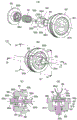
fig. 6 (a) and 6 (c) are perspective views of the drum gear unit, and fig. 6 (b) and 6 (d) are sectional views of the drum gear unit;
the partial view (a1), the partial view (a2), the partial view (a3) and the partial view (a4) of fig. 7 show the gear unit, and the partial views (b1), (b2), (b3), (b4) of fig. 7 are sectional views of the drum gear unit;
FIG. 8 shows a modification of embodiment 1;
fig. 9 is a perspective view of the drum gear unit in the partial views (a), (b), (c), (d) and (e);
fig. 10 is an exploded perspective view of the cleaning unit in sub-views (a), (b), and (c);
fig. 11 (a) and 11 (b) are perspective views of the cartridge;
the section (a) of fig. 12, the section (b) of fig. 12, the section (c) of fig. 12, and the section (d) of fig. 12 show the operation of the drum gear unit;
the section view (a1), the section view (a2), the section view (a3) and the section view (a4) of fig. 13 show the drum gear unit, and the section view (b1), the section view (b2), the section view (b3) and the section view (b4) of fig. 13 show cross-sectional views of the drum gear unit;
fig. 14 is a perspective view of the drum gear unit in section (a) and fig. 14 is a perspective view of the drum gear unit in section (c) and fig. 14 is a sectional view of the drum gear unit in section (d);
the section (a) and the section (b) of fig. 15 show the drum gear unit;
fig. 16 is a sectional view (a), (b), (c) and (d) showing the drum gear unit;
fig. 17 (a), (b), and (c) show drum gear units;
the partial view (a1), the partial view (a2), and the partial view (a3) of fig. 18 show the drum gear unit, and the partial view (b1), the partial view (b2), and the partial view (b3) of fig. 18 are sectional views of the drum gear unit;
fig. 19 is a sectional view (a), (b), (c) and (d) showing the drum gear unit;
fig. 20 (a) and 20 (b) show a drum gear unit;
fig. 21 (a) and 21 (b) show a drum gear unit;
the section (a) of fig. 22, the section (b) of fig. 22, and the section (c) of fig. 22 show the drum gear unit;
the partial view (a1), the partial view (a2), and the partial view (a3) of fig. 23 show the drum gear unit, and the partial view (b1), the partial view (b2), and the partial view (b3) of fig. 23 are sectional views of the drum gear unit;
the partial view (a) of fig. 24, the partial view (b) of fig. 24, and the partial view (c) of fig. 24 show the coupling member, and the partial view (d) of fig. 24, the partial view (e) of fig. 24, and the partial view (f) of fig. 24 are sectional views of the coupling member;
fig. 25 is a diagram (a) showing a modified example of the coupling member, and fig. 25 is a sectional view showing a modified example of the coupling member.
Detailed Description
Hereinafter, embodiments to which the present invention is applied will be described with reference to the accompanying drawings.
Here, an image forming apparatus employing an electrophotographic method (an image forming apparatus for forming an electrophotographic image) is referred to as an electrophotographic image forming apparatus. The electrophotographic method is a method of developing an electrostatic image formed on a photosensitive member with toner. Here, the developing method may be a one-component developing method, a two-component developing method, a developing method such as dry development, or the like. In addition, an electrophotographic photosensitive drum (electrophotographic photosensitive drum) is used for an electrophotographic image forming apparatus, and has a structure in which a photosensitive member (photosensitive layer) is provided on a cylindrical surface layer of a drum-shaped cylinder.
Here, a charging roller, a developing roller, and the like associated with image formation and acting on the photosensitive drum are referred to as process means. In addition, a cartridge including a photosensitive member or a process device (a cleaning blade, a developing roller, or the like) related to image formation is referred to as a process cartridge. In this embodiment, in a process cartridge to be described, a photosensitive drum, a charging roller, a developing roller, and a cleaning blade are integrated into one unit.
In this embodiment, a laser beam printer will be employed in an electrophotographic method for various applications (e.g., multifunction peripherals, facsimile machines, printers, etc.). The reference numerals in the examples are used to refer to the drawings and do not limit the constitution of the present invention. The dimensions and the like in the examples are used for clearly explaining the relationship and do not limit the structure of the present invention.
The longitudinal direction of the process cartridge in the embodiment is a direction substantially perpendicular to a direction in which the process cartridge is mounted to and dismounted from the main assembly of the electrophotographic image forming apparatus. The longitudinal direction of the process cartridge is parallel to the rotation axis of the electrophotographic photosensitive drum (the direction intersecting the sheet feeding direction). In the longitudinal direction, the side of the photosensitive drum of the process cartridge which receives the rotational force from the image forming apparatus main assembly is the driving side (driven side), and the opposite side thereof is the non-driving side. In addition, without particular description, the upper (upper side) and the lower (lower side) are based on the direction of gravity in a state where the image forming apparatus is mounted.
< example 1>
The laser beam printer of this embodiment will be described with reference to the drawings. The cartridge in the present embodiment is a process cartridge in which a photosensitive drum as a photosensitive member (image bearing member/rotatable member), a developing roller as a process device, a charging roller, a cleaning blade are integrated. The cartridge is detachably mountable with respect to the main assembly of the machine. Here, as a rotatable member/rotational member which receives a rotational force from the operation main assembly to rotate, a gear, a photosensitive drum, a flange, a developing roller, and the like are provided in the cartridge.
Referring to fig. 1, the structure and image forming process of a laser beam printer as an electrophotographic image forming apparatus will be described below. Next, a detailed structure of the process cartridge will be explained with reference to fig. 2 and 3.
(laser beam Printer and image formation Process)
Fig. 1 is a sectional view of a laser beam printer main assembly a (hereinafter, apparatus main assembly a) and a process cartridge (hereinafter, cartridge B) as an electrophotographic image forming apparatus. Also, fig. 2 is a sectional view of the cartridge B.
Hereinafter, the apparatus main assembly a refers to a portion of the laser beam printer as an electrophotographic image forming apparatus which does not include the removable cartridge B.
First, referring to fig. 1, a structure of a laser beam printer as an electrophotographic image forming apparatus will be described.
The electrophotographic image forming apparatus shown in fig. 1 is a laser beam printer using an electrophotographic technique, in which a cartridge B is detachably mountable to (detachable from) an apparatus main assembly a. When the cartridge B is mounted in the apparatus main assembly a, the cartridge B is disposed below the laser scanner unit 3 as an exposure means (exposure device).
Further, a sheet tray 4 is provided below the cartridge B, and the sheet tray 4 accommodates a sheet P as a recording medium (sheet) as an image forming object (object) on which an image is formed by the image forming apparatus.
Further, in the apparatus main assembly a, a pickup roller 5a, a pair of feeding rollers 5b, a pair of feeding rollers 5c, a transfer guide 6, a transfer roller 7, a feeding guide 8, a fixing device 9, a pair of discharge rollers 10, and a discharge tray 11 are provided in this order from the upstream side in the feeding direction X1 of the sheet P. The fixing device 9 as a fixing device includes a heating roller 9a and a pressure roller 9 b.
Next, referring to fig. 1 and 2, an overview of the imaging process will be described.
Based on the print start signal, the drum 62 as a rotatable photosensitive drum carrying developer is rotated in the direction of arrow R (hereinafter referred to as the rotation direction R) at a predetermined circumferential speed.
The charging roller 66, to which a bias is applied, contacts the outer circumferential surface of the drum 62 and charges the outer circumferential surface of the drum 62 uniformly.
The laser scanner unit 3 as an exposure device outputs a laser beam L corresponding to image information input to the laser printer. The laser beam L scans and exposes the outer circumferential surface of the drum 62 through an exposure window 74 on the upper surface of the cartridge B. Thereby, a part of the charging drum 62 is neutralized, so that an electrostatic image (electrostatic latent image) is formed on the surface of the photosensitive drum.
On the other hand, as shown in fig. 2, in the developing unit 20 as a developing device, the developer (hereinafter referred to as toner T) in the toner chamber 29 is supplied to the feed screw 43 and is supplied by stirring by rotation, and is supplied to the toner supply chamber 28.
The toner T as a developer is carried on the surface of the developing roller 32 as a developing device (process device, rotatable member) by the magnetic force of the magnetic roller 34 (fixed magnet). The developing roller 32 functions as a toner bearing member (developer bearing member, developing member) that bears developer and supplies it to a developing area to develop an electrostatic image formed on the drum 62. The layer thickness of the toner T supplied to the development area on the peripheral surface of the developing roller 32 is regulated by the developing blade 42. The toner T is frictionally charged between the developing roller 32 and the developing blade 42.
In this way, the toner T carried by the developing roller 32 develops (visualizes) the electrostatic image formed on the drum 62. The drum 62 rotates in the rotation direction R while carrying toner (toner image) developed on the surface thereof. The drum 62 is an image bearing member that bears a toner image.
As shown in fig. 1, at a time correlated with the output time of the laser beam L, the pickup roller 5a, the pair of feeding rollers 5b, and the pair of feeding rollers 5c feed the sheet P stored in the lower portion of the apparatus main assembly a from the sheet tray 4.
Then, the sheet P is supplied to a transfer position (transfer nip) between the drum 62 and the transfer roller 7 through the transfer guide 6. At this transfer position, the toner images are sequentially transferred from the drum 62 as an image bearing member to the sheet P as a recording medium.
The sheet P on which the toner image has been transferred is separated from the drum 62 and fed to the fixing device 9 along the feed guide 8. The sheet P passes through a fixing nip between a heating roller 9a and a pressure roller 9b, which heating roller 9a and pressure roller 9b constitute a fixing device 9. In the fixing nip, an unfixed toner image on the sheet P is fixed to the sheet P by pressurization and heating. After that, the sheet P on which the toner image is fixed is fed by the discharge roller pair 10 and discharged to the discharge tray 11.
On the other hand, as shown in fig. 2, after the toner T is transferred to the sheet, untransferred residual toner remaining on the drum surface without being transferred to the sheet adheres to the surface of the drum 62. The untransferred residual toner is removed by a cleaning blade 77 in contact with the circumferential surface of the drum 62. Thereby, the toner remaining on the drum 62 is removed, and the drum 62 after cleaning is recharged and then used for the image forming process. The toner (untransferred residual toner) removed from the drum 62 is stored in the waste toner chamber 71b of the cleaning unit 60.
In the above description, the charging roller 66, the developing roller 32, and the cleaning blade 77 are used as the process devices acting on the drum 62. In the image forming apparatus of the present embodiment, a method of removing the untransferred residual toner with the cleaning blade 77 is employed. However, it is also possible to employ a system (cleanerless system) in which the untransferred residual toner having the regulated electric charge is recovered simultaneously with the developing action of the developing device. In the cleanerless system, an auxiliary charging member (an auxiliary charging brush or the like) for adjusting the electric charge of the untransferred residual toner is also used as the processing means.
(Structure of Process Cartridge)
Referring to fig. 2 and 3, a detailed structure of the cartridge B will be described.
Fig. 3 is an exploded perspective view of the cartridge B. The cartridge B has a frame that rotatably supports the drum 62 and the developing roller 32. The frame of the cartridge B is detachable into a plurality of units. In the cartridge B of the present embodiment, the cleaning unit 60 and the developing unit 20 are integrated, and the frame of the cleaning unit 60 and the frame of the developing unit 20 constitute the cartridge B.
In this embodiment, the cleaning unit 60 for holding the drum 62 and the developing unit 20 for holding the developing roller 32 are connected by two connecting pins 75. However, the cartridge B may be divided into three or more units. Of course, a plurality of units may not be coupled by a connecting member such as a pin, and only a part of the units may be replaced.
The cleaning unit 60 includes a cleaning frame 71, a drum unit U1, a charging roller 66, a cleaning blade 77, and the like. The cartridge B has a frame that rotatably supports the drum 62 and the developing roller 32.
Drum unit U1 includes drum unit U2, coupling member 86 and pin 88 (see fig. 6) provided at the drive-side end of drum unit U2. The coupling member 86 is for receiving a rotational force for rotating the drum unit U1 from the outside of the drum unit U1.
Further, the drum unit U2 has the drum 62 and a drive-side flange 87 (details will be described later) as a flange member mounted to the drive side of the drum 62.
The rotational force is transmitted from the apparatus main assembly a to the drum 62 through the driving side flange 87 and the coupling member 86.
As shown in fig. 3, the drum 62 is rotatable about a rotational axis L1 (hereinafter referred to as axis L1). The coupling member 86 is rotatable about a rotation axis L2 (hereinafter referred to as axis L2). In this embodiment, coupling member 86 is coupled to the end of drum 62 such that axis L1 of drum 62 and axis L2 of coupling member 86 are substantially coaxial. Therefore, in the following description, the axis L1 and the axis L2 may be described as being the same.
Here, coupling member 86 is configured to be able to advance and retract along axis L2 relative to drum 62 and drive side flange 87. In other words, coupling member 86 may be substantially parallel to at least the direction of extension (axial direction) of axis (L2). The coupling member 86 can take a position (extended position, advanced position, first position) advanced (extended) toward the outside of the drive-side flange 87 and a position (retracted position, second position) retracted toward the inside of the drive-side flange 87 (toward the drum). In other words, the coupling member 86 may reciprocate in the axial direction between the extended position and the retracted position. Details will be described below with reference to the partial diagrams (b1) — (b4) of fig. 7.
As shown in fig. 2 and 3, the developing unit 20 includes a toner accommodating container 22, a bottom member 21, a first side member 26L (non-driving side), a second side member 26R (driving side), a developing blade 42, a developing roller 32, and a magnet roller 34. Here, the toner accommodating container 22 accommodates a feed screw 43 (stirring blade) as a supply member that supplies toner, and accommodates toner T as a developer. In addition, the developing unit 20 is provided with a compression spring 46, and the compression spring 46 applies an urging force to regulate the unit posture between the developing unit 20 and the cleaning unit 60. Also, the cleaning unit 60 and the developing unit 20 are rotatably connected to each other by a connecting pin 75 as a connecting member to constitute a cartridge B.
Specifically, the rotation holes 23bL, 23bR are provided at free ends of the arm portions 23aL, 23aR, and the arm portions 23aL, 23aR are provided at opposite ends of the developing unit 20 in the longitudinal direction (the axial direction of the developing roller 32). The rotation holes 23bL and 23bR extend parallel to the axis of the developing roller 32.
In addition, fitting holes 71a for fitting the connecting pins 75 are provided at each longitudinal end portion of the cleaning frame 71 as a frame of the cleaning unit 60. Then, the connection pins 75 are inserted into the rotation holes 23bL, 23bR and the fitting holes 71a while the arm portions 23aL, 23aR are aligned with predetermined positions of the cleaning frame 71. Thereby, the cleaning unit 60 and the developing unit 20 are rotatably coupled to each other around the connection pin 75 as a connection member.
At this time, the compression springs 46 provided on the bases of the arm portions 23aL, 23aR abut against the cleaning frame 71, so that the developing unit 20 is pushed toward the cleaning unit 60 with the connecting pin 75 as the rotation center.
Thereby, the developing roller 32 as the process device is reliably pushed toward the drum 62 as the rotatable member. The developing roller 32 is held at a position at a predetermined distance from the drum 62 by spacers (not shown) as annular distance holding members attached to opposite end portions of the developing roller 32.
(mounting and dismounting Process cartridge)
With reference to fig. 4 and 5, the operations of mounting and dismounting the cartridge B to and from the apparatus main assembly a in the above-described structure will be described.
Fig. 4 shows how the cartridge B is mounted to and dismounted from the apparatus main assembly a. Fig. 4 is a perspective view of a partial view (a) from the non-driving side, and fig. 4 is a perspective view of a partial view (b) from the driving side. The driving side is an end portion of the cartridge B in the longitudinal direction where the coupling member 86 is provided.
The opening/closing door 13 is rotatably mounted to the apparatus main assembly a. Fig. 4 shows the apparatus main assembly a in a state where the opening/closing door 13 is opened.
An opening O1 is provided in the apparatus main assembly a, and a mounting space for mounting the cartridge B is provided inside the apparatus main assembly a. A driving head (driving shaft, transmission member) 14 and a guide member 12 as a guide mechanism are provided inside the apparatus main assembly a.
Here, the driving head 14 is a main assembly side transmission mechanism provided at a side portion of the apparatus main assembly a, transmits a driving force to the cartridge B mounted in the apparatus main assembly a, and is engageable with a coupling member 86 of the cartridge B. After engagement, by rotation of the driving head 14, the rotational force can be transmitted to the cartridge B. Here, the driving head 14 is supported by the apparatus main assembly a to be rotatable about an axis L4. In addition, the drive head 14 is provided with a drive pin 14b (see fig. 7) as a force application portion for applying a rotational force.
The guide member 12 as a guide mechanism is a main assembly side guide member for guiding the cartridge B into the apparatus main assembly a. The guide member 12 may be a plate-like member provided with a guide groove. The upper end of the guide member 12 may contact with the lower surface of the cartridge B to support the cartridge B from below and guide (guide) attachment and detachment of the cartridge B.
Referring to fig. 5 and 6, a structure for transmitting the rotational force input from the driving head 14 to the cartridge B to the drum 62 will be described. Fig. 5 is an illustration of a coupling member 86 as a driving force transmitting portion, in which a partial view (a) of fig. 5 and a partial view (b) of fig. 5 are side views, and a partial view (c) of fig. 5 is a perspective view.
The partial view (a) of fig. 6 and the partial view (b) of fig. 6 are illustrations of the drum gear unit U2 including the coupling member 86, the partial view (a) of fig. 6 and the partial view (c) of fig. 6 are perspective views, and the partial views (b) and (d) of fig. 6 are sectional views taken along the s1 plane shown in the partial views (a) and (c) of fig. 6. The coupling member 86 is movably provided in the drum unit U1, and the partial view (a) of fig. 6 and the partial view (c) of fig. 6 show different positions of the coupling member 86 in the drum unit U1.
As shown in fig. 5, the coupling member 86 includes a supported portion 86a, a rotational force transmitting portion 86b, and a coupling portion 86 c. First, the supported portion 86a has a cylindrical shape with the rotation axis L1 of the coupling member 86 as its central axis. Next, the rotational force transmitting portion 86b includes: a cylindrical force application portion 86b1 that projects in a direction perpendicular to the rotation axis L1; a large diameter portion 86b4 including a cylindrical shape having a diameter larger than that of the supported portion 86 a; and a shaft portion 86b3 connecting the large-diameter portion 86b4 and the coupling portion 86 c. A stepped portion 86b2 is provided between the large diameter portion 86b4 and the supported portion 86 a. The connecting portion 86c includes a base portion 86c3 having a spherical shape, a pair of protruding portions (protruding portions) 86c1 protruding outward from the rotation axis L1 from the base portion 86c3, and a recessed portion 86c4 of a spherical surface concentric with the base portion 86c3, the recessed portion 86c4 being formed by hollowing out the base portion 86c 3.
The connecting portion 86c is a portion for coupling with the driving head 14 provided in the main assembly. A pair of protruding portions 86c1 provided on the coupling portion 86c abut the drive pins 14b of the drive head 14 to receive a rotational force (drive force) from the drive head 14. The contact portion of the protruding portion 86c1 with the drive pin 14b is a force receiving portion (rotational force receiving portion, drive force receiving portion) for receiving the rotational force. Coupling member 86 and drum 62 are rotated by the rotational force received by extension 86c 1.
The recessed portion 86c1 is a surface formed by recessing the base portion 86c3 and faces the side opposite to the supported portion 86a (i.e., the free end side of the coupling member 86). The protruding portion 86c1 protrudes from the surface near the recessed portion 86c 1. Specifically, the base portion 86c3 has an annular surface (edge) surrounding the recess 86c1, and the protruding portion 86c1 protrudes from the annular edge. The coupling member 86 has a plurality of projections 86c1 (two in the present embodiment).
Projection 86c1 extends from drum 62 in a direction away from axis L1 (axis L2). In other words, the protruding portion 86c1 protrudes toward the tip of the coupling member 86. Coupling member 86 is furthest from drum 62 in the direction of axis L1 at the end of projection 86c 1.
Base 86c1 forms an end portion (first end) of coupling member 86. Extension 86c1 extends further from base 86c1 toward the distal end of coupling member 86.
Further, the supported portion 86a and the large diameter portion 86b4 are arranged inside the drum unit and are connected and fixed to a drive-side flange 87 which will be described later. In other words, the supported portion 86a and the large diameter portion 86b4 form a fixed end (second end) connected to the driving-side flange 87.
The shaft portion 86b3 is a connecting portion that connects the first end and the second end of the link member. The distance from the axis L2 of the coupling member 86 to the surface of the shaft portion 86b (i.e., the radius of the shaft portion 86 b) is shorter than the distance from the protruding portion 86c1 to the axis. The distance between the protruding portion 86c1 and the axis L2 differs depending on the position of the protruding portion 86c1, but the shortest distance and the longest distance from the protruding portion 86c to the axis L2 are longer than the distance from the axis L2 to the surface of the shaft portion 86 b.
The two protruding portions 86c1 are inclined at an angle θ 1 and an angle θ 2 with respect to the rotation axis L1. Also, the angles θ 1 and θ 2 are substantially equal.
That is, the pair of protruding portions 86c1 has a conical shape with the rotation axis L1 as the center axis, and has a line inclined at an angle θ 1 with respect to the rotation axis L1 as the generatrix. In other words, the shape of the protruding portion 86c1 of the coupling portion 86c is such that the distance from the rotation axis L2 increases toward the tip of the coupling member 86 (the tip of the protruding portion 86c 1) (i.e., as going away from the drum 62).
Projection 86c1 has an inner surface facing axis L2 and an outer surface facing away from axis L2. Both the inner and outer surfaces of the projection 86c1 are configured such that the distance from the axis L2 increases toward the tip of the projection 86c 1.
In other words, the outer surface of projection (protrusion) 86c1 is farther from axis L2 as it moves away from drum 62 in the direction of axis L2 (axis L1). The inner surface of projection (protrusion) 86c1 increases in distance from axis L2 as it moves away from drum 62 in the direction of axis L2 (axis L1). The inner and outer surfaces of the extension 86c1 are the greatest distance from the axis L2 at the tip of the extension.
Referring to fig. 6, the drum gear unit U2 in which the coupling member 86 is incorporated will be described. As shown in fig. 6, the drum gear unit U2 includes a coupling member 86, a drive-side flange 87, a cover member 88, and a compression spring 89.
The drive-side flange 87 is a flange (drum flange) fixed to an end portion on the drive side of the drum 62, and has a gear on the outer periphery thereof. Therefore, the drive-side flange 87 is sometimes referred to as a drum gear. The gear on the driving side flange 87 meshes with a gear provided at the end of the developing roller 32, so that when the drum 62 rotates, the driving force is transmitted to the developing roller 32.
The coupling member 86 is disposed such that at least the rotational force transmitting portion 86b1 is accommodated in the hollow portion 87a of the drive side flange (drum gear) 87, and at least a part of the coupling portion 86c projects outward beyond the drive side flange 87. The cover member 88 is fixed to the driving-side flange 87 by adhering the joining surface 88d to the surface 87c of the driving-side flange 87, and the supported portion 86a of the coupling member 86 is supported by the supporting portion 88a so as to be movable in the direction of the rotation axis L1.
Thereby, the coupling member 86 can be moved in the direction of the rotation axis L1 (the direction of the arrow X4 and the direction of the arrow X5) in the drum gear unit U2. Here, the coupling member 86 is prevented from being disengaged in the direction of the arrow X5 by the abutment of the step portion 86 with the free end portion 88c of the support portion 88a, and the coupling member 86 is prevented from being disengaged in the direction of the arrow X4 by the abutment between the rotational force transmitting portion 86b1 and the retaining portion 87b of the drive side flange 87. A compression spring 89 is provided between the rotational force transmitting portion 86b1 of the coupling member 86 and the spring receiving portion 88b of the cover member 88. Thereby, the coupling member 86 is urged in the direction (arrow X4 direction) in which the coupling portion 86c projects from the drive-side flange 87.
When the rotational force is transmitted to the coupling member 86, the rotational force transmitting portion 86b1 comes into contact with the rotational force receiving portion 87d1 of the drive side flange 87 to transmit the rotational force to the drive side flange 87. The press-fit portion 87e of the drive-side flange 87 is press-fitted and fixed to the inner diameter portion of the drum 62 (see fig. 3). With the above structure, the rotational force is transmitted from the drive head 14 to the drum 62. Coupling member 86 is connected to the end of drum 62 by drive side flange 87, and coupling member 86 and drum 62 interlock with each other. The manner of coupling the coupling member and the drum 62 is merely one example. It is sufficient that the drum 62 can be rotated by rotation of the coupling member 86.
Then, referring to fig. 7, the operation of the coupling member 86 when the cartridge B is dismounted from the apparatus main assembly a will be described. Fig. 7 is an illustration of the dismounting operation of the drum unit U2, in which the main assembly a is shown only by the driving head 14 and the coupling guide (guide member 15). The drum gear unit U2 of the cartridge B is sequentially disengaged from (a1) to (a4) of fig. 7, fig. 7(a1) showing a state in which the driving of the apparatus main assembly a is completed. The partial views (b1) to (b4) of fig. 7 are sectional views (S2 sectional views) taken along the line S2-S2 of the structures shown in the partial views (a1) to (a4) of fig. 7. For illustration, the drive head 14 is not shown in cross-section.
A guide member 15 is provided in the vicinity of the drive head 14 to guide the coupling member. When the inside of the apparatus main assembly a is viewed through an opening O1 (see fig. 2) of the apparatus main assembly a, the guide member 15 is disposed behind the driving head 14.
As shown in the partial view (a1) of fig. 7 and the partial view (b1) of fig. 7, when the coupling member 86 is positioned at the extended position, the coupling member 86 is engaged (coupled) with the drive head 14. When the cartridge B is moved in the direction of the arrow X3 after the rotation of the drive head 14 is completed, the coupling member 86 is moved in the direction of the arrow X3 together with the drum gear unit U2. Meanwhile, the upstream side of the coupling member 86 in the detachment direction of the cartridge B is in contact with the drive head 14. In other words, the inner surface of the recess 86c4 or the projection 86c1 is in contact with the drive head 14. This causes coupling member 86 to move in the direction of arrow X5 (see partial view (a2) and partial view (b2) of fig. 7).
In this embodiment, the contact portion of the drive head 14 and the contact portion of the coupling member 86 are both inclined with respect to the axis L1 and the axis L4 (see partial views (b1) to (b4) of fig. 7). That is, the free end of the drive head 14 is inclined with respect to the axis L4 of the drive head 14. In addition, the surface of the recess 86c4 and the surface of the protruding portion 86c1 of the coupling member are also inclined with respect to the axis L1 (axis L2).
Therefore, when the cartridge B is moved in the X3 direction and the drive head 14 and the coupling member 86 are in contact, the force F1 received by the coupling member 86 from the drive head 14 has a component in the direction of arrow X5 (component in the axial direction). Thereby, the coupling member 86 is retracted in the direction of arrow X5 (toward the drum) by a force F1 received from the contact portion with the drive head 14.
However, it is sufficient that at least one of the contact portion between the drive head 14 and the inner surface of the coupling member 86 and the drive head 14 is inclined with respect to the axis L2 of the coupling member 86. In this case, force F1 received by coupling member 86 has a component for moving coupling member 86 in the direction of arrow X5.
In this embodiment, the inner surface of projection 86c1 facing axis L2 is configured such that the distance from axis L2 increases as it moves in its entirety away from drum 62 in the direction of axis L1. However, it is not necessary that the entire protruding portion 86c1 have such a structure. It is sufficient that at least a part of the inner surface of the protruding portion 86c1 (i.e., at least a part that is in contact with the driver head 14) has the above-described inclination. If so, coupling member 86 is susceptible to retraction toward the drum in the direction of axis L2 when the inner surface of extension 86c1 contacts drive head 14.
When the cartridge B is further moved in the arrow X3 direction from the state shown in the partial view (a2) of fig. 7 and its partial view (B2), the coupling member 86 is further moved in the arrow X5 direction. Finally, the coupling member 86 is brought into the state shown in the partial view (a4) and the partial view (b4) of fig. 7 from the state shown in the partial view (a3) and the partial view (b3) of fig. 7. At this time, the free end 86c12 of the projecting portion 86c1 does not overlap the drive head 14 in the direction of the rotation axis L1. Thereby, the coupling member 86 can surround the driving head 14, and the cartridge B can be pulled out from the apparatus main assembly a.
In this embodiment, coupling member 86 is configured to move substantially parallel to axis L1 of drum 62. Coupling member 86 moves along axis L2 while maintaining axis L2 of coupling member 86 coaxial with axis L1 of drum 62 (i.e., maintaining the state in which axis L1 and axis L2 overlap each other).
However, coupling member 86 may move in a direction inclined with respect to axis L1, that is, axis L2 may not overlap with axis L1. For example, if coupling member 86 is moved along axis L2, its direction of movement need not be parallel to axis L1. In this case, the angle of axis L2 relative to axis L1 is substantially constant before and after coupling member 86 is moved along axis L2.
In this embodiment, coupling member 86 moves along axis L2 while maintaining the state in which the angle of axis L2 with respect to axis L1 is substantially 0 degrees.
As described above, the projection 86c1 is formed such that the distance from the axis L2 increases as the distance from the drum 62 increases in the direction of the axis L1. In other words, the distance from the axis L2 becomes larger toward the tip of the projecting portion 86c1, that is, the projecting portion 86c1 is enlarged toward the leading end thereof in the radial direction of the coupling member 86.
Therefore, as shown in the partial views (b1), (b2), (b3) and (b4) of fig. 7, the protruding portion 86c1 has a small diameter on the rear end side (root side), so that a large distance can be secured between the outer surface of the protruding portion 86c1 and the guide portion 15a of the member 15 in a state where the coupling portion 86c is in contact with the drive head 14. Thereby, the coupling member 86 can be moved without the engaging portion 86c simultaneously contacting the driving head 14 and the guide member 15. That is, when the coupling member 86 moves in the direction of the arrow X5, the movement of the coupling member 86 is not hindered by the guide member 15. In other words, the engagement between the coupling member 86 and the driving head 14 can be smoothly released, and the load applied to the user when the cartridge B is taken out from the apparatus main assembly a can be reduced.
Here, the guide portion 15a is an inclined portion inclined with respect to the axis L4 of the drive head 14, and is inclined in a direction facing the drive head 14 g. Since the guide portion 15a is inclined with respect to the axis L4, the guide member 15 projects close to the axis L4 with the projecting portion facing the shaft portion 86b3 (refer to fig. 5) of the coupling member 86. As shown in fig. 5, the shaft portion 86b3 of the coupling member 86 has a diameter smaller than the diameters of the protruding portion 86c1 and the base portion 86c3, so that the protruding portion of the guide member 15 can be prevented from coming into contact with the coupling member 86.
As described above, according to this embodiment, the projecting portion 86c1 expands radially outward as it moves away from the drum flange 62 in the direction of the axis L1 (i.e., as it moves toward the tip (free end) of the coupling member 86). Therefore, even if the guide member 15 is provided in the main assembly of the apparatus, the coupling member 86 can be smoothly retracted from the driving head 14 when the cartridge B is taken out from the apparatus main assembly a.
The entire projecting portion 86c1 need not have the above-described shape, and it is sufficient if the portion required for passing through the gap between the guide member 15 and the drive head 14 has the above-described shape.
That is, at least a portion of the projection 86c1 may be configured to increase in distance from the axis L2 as the distance from the drum flange 62 increases in the direction of the axis L1.
In this embodiment, the coupling member 86 is formed so as not to contact the guide member 15 when the coupling member 86 is retracted while contacting the drive head 14. However, even if the coupling member 86 becomes large, a structure may be adopted in which the coupling member 86 is simultaneously brought into contact with the drive head 14 and the guide member 15 at the time of retraction. For example, even if the coupling member 86 is in contact with the drive head 14 and the guide member 15 at the same time, if the guide member 15 is elastically deformed, the load is not so large, for example, when the coupling member 86 is retracted in the direction of the arrow X5. The inner surface of the protruding portion 86c1 is inclined along the tip of the driving head 14, and the outer surface of the protruding portion 86c1 is inclined along the guide member 15. Thus, the coupling member 86 can be moved to the retracted position with the outer surface of the protruding portion 86c1 guided by the guide member 15 and the inner surface of the protruding portion 86c1 guided by the drive head 14. The coupling member 86 can be smoothly disengaged from the drive head 14.
In other words, if the load acting on the user when detaching the cartridge B is within the allowable range, the wall thickness of the coupling portion 86c may be increased and the coupling member 86 may be brought into contact with the guide member 15 when the coupling member 86 is retracted. Increasing the wall thickness of the coupling portion 86c can improve the strength of the coupling portion 86c, so that the rotational accuracy of the drum 62 can be improved.
In this embodiment, the projecting portion 86c1 projects from a base portion 86c3 provided in the coupling portion 86c, but as shown in the division views (a) - (c) of fig. 8, a pair of projecting portions 186c1 may project from the shaft portion 86b 3.
In this case, the projecting portion 186c1 as the rotational force receiving portion (driving force receiving portion) has a shape expanding outward in the radial direction of the coupling member 186 toward the tip end thereof.
Referring to fig. 24, the operation of the coupling member 86 when the cartridge B is mounted in this embodiment will be described. The partial view (a) of fig. 24, the partial view (b) of fig. 24, and the partial view (c) of fig. 24 show the coupling member 86. The partial views (d), (e) and (f) of fig. 24 are sectional views of the coupling member 86.
The section (d), the section (e) and the section (f) of fig. 24 are sectional views corresponding to the section (a), the section (b) and the section (c) of fig. 24, respectively.
In this embodiment, if the coupling member 86 (drum 62) is not in the predetermined phase, the cartridge B cannot be mounted in the apparatus main assembly a or is difficult to mount. In other words, if the coupling member 86 has the phase shown in the partial diagram (a) of fig. 24 and the partial diagram (d) of fig. 24, the outer surface of the projecting portion 86c1 (coupling portion 86c) of the coupling member 86 collides against the driving head 14 of the apparatus main assembly a. In this case, the cartridge B cannot be mounted, or is difficult to mount.
On the other hand, at the time of mounting the cartridge B, in the case of the phases shown in the partial diagram (B) of fig. 24 and the partial diagram (e) of fig. 24, the protruding portion 86c1 of the coupling member 86 does not contact the drive head 14. On the other hand, the base portion 86c3 of the coupling member 86 contacts the drive head 14. However, when the base portion 86c3 comes into contact with an inclined portion (curved surface portion) provided at the tip end of the drive head 14, the coupling member 86 is retracted in the axial direction. Therefore, the mounting of the cartridge B is not hindered. Finally, the state shown in the partial view (c) of fig. 24 and the partial view (f) of fig. 24 is established, and the axis of the coupling member 86 and the axis of the drive head 14 are substantially coaxial with each other. The coupling member 86 is engageable with the drive head 14 and becomes capable of receiving a driving force (rotational force) from the drive head 14.
On the other hand, in the state shown in the partial diagram (a) of fig. 24 and the partial diagram (d) of fig. 24, in some cases, the user cannot mount the cartridge B in the apparatus main assembly a. In this case, it is necessary to take out the cartridge B from the apparatus main assembly a and rotate the coupling member 86 until reaching a state shown in partial view (B) of fig. 24 and partial view (d) of fig. 24. Therefore, it is desirable to shorten the width of the protruding portion 86c1 so that the protruding portion 86c1 does not collide with the drive head 14 when the cartridge B is mounted as many as possible.
Around the base portion 86c, an area where the protruding portion 86c1 exists is longer than an area where the protruding portion 86c1 does not exist. In other words, the sum of the widths of the two extensions 86c1 is less than half the circumference of the base 86 c.
As shown in partial view (a) of fig. 25 and partial view (b) of fig. 25, an inclined portion 86c5 may be provided at the tip of the base portion 86c3 so that the coupling member 86 is easily retracted when in contact with the drive head 14.
The inclined portion 86c5 is inclined with respect to the axis of the coupling member 86. Therefore, when the inclined portion 86c5 comes into contact with the drive head 14, the coupling member 86 receives a force in the axial direction. This force effectively retracts the coupling member 86 in the axial direction.
If at least one of the contact portion of the coupling member 86 and the contact portion of the drive head 14 is inclined with respect to the axis of the coupling member 86, the coupling member 86 can be retracted in the axial direction by receiving a force in the axial direction.
< example 2>
In the description of the present embodiment, the same reference numerals as those in embodiment 1 are assigned to elements having corresponding functions in the embodiment, and detailed description thereof is omitted.
Referring first to fig. 9, the structure of the drum gear unit U23 will be described. Fig. 9 is an illustration of the structure of the drum gear unit U23, and fig. 9 is an exploded perspective view shown in the assembly order from the partial views (a) to (e) of fig. 9.
Fig. 9 (a) and 9 (b) are exploded views of the first unit U21. First unit U21 includes a coupling member 286, a translation cam 288, and a rotation cam 289. The supported portion 286a of the coupling member 286 is assembled to pass through the hole portion 288a of the translation cam 288 and the hollow portion 289a of the rotation cam 289.
On the coupling member 286, a pressed portion 286b is provided between the shaft portion 286a and the coupling portion 286 c. The translation cam 288 includes a cylindrical surface 288b, a protruding portion 288c protruding radially outward from the cylindrical surface 288b, a cut-out portion 288d provided by cutting out a portion of the cylindrical surface 288b, and a pressing portion 288 e.
The rotating cam 289 has a hollow portion 289a, a cut-away portion 289c, an outline portion 289b, and an extended portion 289 d. Hollow portion 289a houses translation cam 288 and coupling member 286 and rotatably supports cylindrical surface 288 b.
In addition, a cut-away portion 289c is formed to cut away a part of the hollow portion 289a and accommodate the protruding portion 288 c. Here, the cut-out portion 289c is provided with an inclined surface portion 289c1, and the projecting portion 288c opposite thereto is also provided with an inclined surface portion 288c 1.
Fig. 9 (c) is an exploded view of the second unit U22. The second unit U22 includes a first unit U21, an auxiliary member 290, and a pin 291. The coupling member 286 of the first unit U21 is assembled such that the shaft portion 286a passes through the hole 290a of the auxiliary member 290. Thereafter, the pin 291 is inserted through the side hole portion 290b of the auxiliary member 290 and the hole portion 286d of the coupling member 286.
Fig. 9 (d) is an exploded view of the drum gear unit U23. The drum gear unit U23 includes a second unit U22, a driving side flange (drum gear 287), a compression spring 292, and a cover member 294. The drum gear 287 accommodates the second unit U22 in the inner portion 287a, and the shaft portion 286a of the coupling member 286 passes through a hole (not shown) of the drum gear 287 and projects toward the cover member 294 (in the direction of the arrow X5). Here, the second unit U22 is inserted such that the pin 291 is located in the transmission portion 287b of the hollow portion 287. The shaft portion 286a further passes through an inner diameter portion 292a of the compression spring 292, and a cover member 294 is fixed to the free end. The compression spring 294 abuts against the spring abutment portion 294b of the cover member 294 and a spring abutment portion (not shown) of the drum gear 287.
As shown in (e) of fig. 9, the drum gear unit U23 is assembled such that a protruding portion 289d of the rotating cam 289 protrudes from the drum gear 287 in the arrow X4 direction. In this state, the compression spring 292 is compressed, and urges the coupling member 286 to move in the direction of the arrow X5 with respect to the drum gear 287 together with the cover member 294.
The rotational force transmitted to the coupling member 286 is transmitted to the drive side flange (the drum gear 287) via the pin 291 and the transmission portion 287b of the drum gear 287.
Referring to fig. 10, the structure of the cleaning unit 61 will be described. A drum gear unit U23 is fixed to one end of the drum 62. The drum gear unit U23 and the drum 62 constitute a drum unit U12. The drum unit U12 is disposed in the cleaning frame 71 and is rotatably supported in the cleaning unit 61 by a bearing 293. The support portion 293a of the bearing 293 rotatably supports the outer shape portion 289b of the rotating cam 289. In addition, the stop 293b is assembled into a cut-out 288d into the translating cam 288. Thus, the rotating cam 289 may rotate relative to the bearing 293, and the translating cam 288 may not rotate relative to the bearing 293.
Referring to fig. 11, the structures of the developing unit 21 and the cartridge B will be described. The developing unit 21 is connected to the cleaning unit 61 as in embodiment 1. In addition to this, the lever member 297 is also connected to the developing unit 21 and the cleaning unit 61.
A rod member 297 is provided on the second side member 226R of the cartridge B and extends toward the tip end of the rod member 297 in a direction away from the drum. In other words, the tip of the lever member 297 protrudes away from the second side member 226R.
The second side member 226R is a part of the frame of the cartridge B and forms a side surface of the cartridge B. That is, the second side member 226R is disposed at the end of the cartridge B in the direction of the axis L1 of the drum 62.
The lever member 297 is provided with an extension 297a, a long hole portion 297b and a bent portion 297 c. The long hole portion 297b is connected to the second side member 226R by the fixing member 295, is held movably in the long axis direction of the oblong hole with respect to the second side member 226R, and is rotatable around the fixing member 295. A lever spring (compression spring) is provided between the spring abutment portion 297c1 of the curved portion 297c and the second side member 226R to urge the lever member 297 in the direction of arrow X3. The pressed portion 297c2 of the curved portion 297c is a portion to be pushed by a cartridge pushing portion (not shown) of the opening/closing door 13 when the cartridge B is mounted to the apparatus main assembly a and when the opening/closing door 13 of the apparatus main assembly a is closed. The protruding portion 297a is inserted into a hole 289d1 formed in a protruding portion 289d of the rotating cam 289.
Referring to fig. 12, the operation of the lever member 297 and the drum gear unit U23 will be described. Fig. 12 (a) and 12 (b) are diagrams of the operation of the lever member 297, and fig. (c) and (d) thereof are diagrams of the operation of the drum gear unit U23.
The lever member 297 and the coupling member 286 are configured to move in association with the opening and closing operation of the opening/closing door 13 (see fig. 4). Fig. 12 (a) shows a state in which the cartridge B is mounted in the apparatus main assembly and the opening/closing door 13 is opened. As shown in fig. 12 (b), when the opening/closing door 13 is closed from this state, the pressed portion 297c of the lever member 297 is pushed in the direction of arrow X6 by the cartridge pushing portion (not shown) of the opening/closing door 13. Thus, the lever member 297 moves in the rightward direction of fig. 12 (b) along the longitudinal direction of the long hole 297 b. As the lever member 297 moves, the protruding portion 297a rotates the rotating cam 289 in the direction of the arrow R3 through the hole 289d1 of the rotating cam 289.
That is, when the rotating cam 289 is rotated from the state shown in (c) of fig. 12, the state shown in (d) of fig. 12 is established. When the rotating cam 289 is rotated by the movement of the lever member 297, as shown in fig. 12 (d), the inclined portion 289c1 is in contact with the protruding portion 288c of the translation cam 288. At this time, since the translation cam 288 cannot rotate relative to the bearing 293 as described above, in order to avoid interference with the inclined portion 289c1, the protruding portion 288c climbs the inclined portion 289c1 to move in the direction of the arrow X4 (outward in the axial direction).
When moving in the direction of arrow X4, translation cam 288 pushes against coupling member 286. Therefore, coupling member 286 also moves in the direction of arrow X4. More specifically, pressing portion 288e of translation cam 288 pushes pressed portion 286b of coupling member 286 to apply a force in the direction of arrow X4, so that coupling member 286 moves in the direction of arrow X4.
That is, when the opening/closing door 13 (see fig. 4) is closed, the coupling member 286 advances in a direction to approach the driving head 14. Thereby, a coupling portion (driving force receiving portion) 286c provided on the coupling member 286 can be engaged with the driving head 14. In other words, the coupling portion 286c becomes a state capable of receiving the rotational force (driving force) from the driving head 14.
The lever member 297 is an operation member operated by the opening/closing door 13.
Referring to the partial views (a1) to (a4) of fig. 13 and the partial views (b1) to (b4) of fig. 13, the movement of the drum gear unit U23 (coupling member 286) will be explained. The drawings show the process of mounting the cartridge B in the main assembly a and the process of closing the door 13 after mounting the cartridge B.
In fig. 13, as for the apparatus main assembly a, only the driving head 14 and the guide member 15 are shown.
In the process of mounting the cartridge B in the apparatus main assembly a, the coupling member 286 is moved in the rightward direction (the direction of arrow X2) in the partial view (a1) of fig. 13 and the partial view (B1) of fig. 13. At this time, the tip 286c12 of the coupling member 286 is located substantially at the same position as the tip of the drive head 14.
As shown in the partial view (a2) of fig. 13 and the partial view (B2) of fig. 13, in the process of mounting the cartridge B, the mounting-direction downstream side of the coupling member 286 contacts the guide member 15. More specifically, the protruding portion 286c1 of the coupling member 286 contacts the guide portion 15a of the guide member 15. In this state, the cartridge B is further inserted into the apparatus main assembly a, whereby the coupling member 286 is moved in the right direction. Then, the projecting portion 286c1 receives a force from the guide portion 15a, so that the coupling member 286 moves in the arrow X4 direction in (b2) of fig. 13 to the state shown in the partial view (a3) and the partial view (b3) of fig. 13.
That is, the projecting portion 286c1 and the guide portion 15a are inclined with respect to the axis L1 of the coupling member 286. Therefore, when the protruding portion 286c1 and the guide portion 15a are in contact, the force that the protruding portion 286c1 receives from the guide portion 15a has a component in the direction of the axis L1. In other words, the force received by the protruding portion 286c1 from the guide portion 15a has an upward component in (b2) of fig. 13. By this force, the linking member 286 moves upward in (B2) of fig. 13 to the state of the partial views (a3), (B3) of fig. 13 in accordance with the mounting operation of the cartridge B. The partial views (a3) and (B3) of fig. 13 show the state in which the cartridge B is fully loaded into the apparatus main assembly a but the opening/closing door 13 (see fig. 4) is still open. At this time, axis L2 of coupling member 286, axis L1 of the drum, and axis L4 of drive head 14 are substantially coaxial with one another.
When the opening/closing door 13 is closed from the state shown in the partial view (a3) and the partial view (b3) of fig. 13, the rotating cam 289 is rotated in the clockwise direction (the arrow R3 direction) in (a4) of fig. 13 by the above-described mechanism. Thereby, the coupling member 286 is further advanced toward the drive head 14. Thereby, the coupling member 286 becomes a state engageable with the driving head 14 so as to receive the driving force from the driving head 14. In other words, when the driver head 14 is rotated in this state, the drive pin 14b provided on the driver head 14 is engaged with the projecting portion 286c1 of the coupling member 286, so that drive is transmitted from the drive pin 14b to the coupling member 286. The contact portion of the protruding portion 286c1 that is in contact with the drive pin 14b is a rotational force receiving portion (force receiving portion, driving force receiving portion) that receives a rotational force from the drive pin 14 b.
In this embodiment, the coupling member 286 is gradually moved from the retracted position (second position) to the extended position (first position) in the process until the cartridge B is mounted to the apparatus main assembly a and the opening/closing door 13 is closed. When the cartridge B is moved to the inside of the apparatus main assembly a, the outer surface of the projecting portion 286c1 is guided by the guide portion 15a, so that the coupling member 286 is slightly brought close to the projecting position from the retracted position (partial views (a3), (B3) of fig. 13). Thereafter, when the opening/closing door 13 is closed, the link member 286 is completely moved to the extended position in association with the movement of the rod member 297, so that the link member 286 can be coupled with the driving head 14 (fig. 13, part (a4) and part (b 4)).
However, in the process of moving the cartridge B to the inside of the apparatus main assembly a, the outer surface of the projecting portion 286c1 does not necessarily need to contact the guide portion 15a, and the coupling member 286 does not need to move in the direction of the axis L2. Another structure is possible in which, when the cartridge B is inserted into the apparatus main assembly a, the coupling member 286 is not in contact with the guide portion 15a and is held in a state of the retracted position. Even in such a case, the coupling member 286 is moved from the retracted position to the extended position by the closing operation of the opening/closing door 13.
When the cartridge B is dismounted from the apparatus main assembly a, the cartridge B performs the operations in the reverse order of the above-described processes, contrary to the case of dismounting the cartridge B from the apparatus main assembly a. First, when the opening/closing door 13 is opened, a force in the X6 direction (see (b) of fig. 12) cannot be applied to the lever member 297, and the lever member 297 is moved in the direction of arrow X3 (fig. 11) by the urging force of the spring 296. Then, the rotating cam 289d is rotated in the direction of the arrow R9 in (a4) of fig. 13, and the urging force of the compression spring 292 moves the coupling member 286 in the direction of the arrow X5 (partial view (a3), partial view (b3) of fig. 13). When the cartridge B is further pulled out, the urging force of the compression spring 292 causes the link member 286 to further move in the direction of the arrow X5 (the partial view (a2) and the partial view (B2) of fig. 13), and finally the state shown in the partial views (a1) and (B1) of fig. 13 is established. Thereby, the cartridge B can be removed from the apparatus main assembly a.
When the cartridge B is dismounted from the apparatus main assembly a, the dismounting-direction upstream side of the coupling member 286 is in contact with the guide portion 15 a.
Also, in this embodiment, as in embodiment 1, at least a part of the outer surface of projecting portion 286c1 of coupling member 286 is inclined with respect to axis L2.
The outer surface of the protruding portion 286c1 is shaped such that it expands (increases in distance from the axis L2) in the radial direction of the coupling member 286 toward the tip (free end) thereof. In other words, the rear end of the protruding portion 286c1 has a smaller diameter than the tip end. Therefore, it is possible to ensure a wide distance between the guiding portion 15c and the coupling member 286 in mounting and dismounting the cartridge B to and from the apparatus main assembly a (see the partial view (B2) and the partial view (B3) of fig. 13). The protruding portion 286c1 of the coupling member 286 avoids interference with the guide member 15. Therefore, the coupling member 286 can smoothly perform coupling and decoupling with respect to the drive head 14.
That is, at the time of mounting or dismounting the cartridge B, even when the outer surface of the protruding portion 286c1 comes into contact with the guide portion 15c, the guide portion 15c does not prevent the protruding portion 286c1 from moving, and the protruding portion 286c1 is smoothly guided by the guide portion 15 c. This makes it easy to mount and dismount the cartridge B.
The outer surface of projection 286c1 faces away from axis L2 of coupling member 286. In this embodiment, the distance of the entire outer surface from axis L2 increases as it moves away from drum 62 in the direction of axis L1. In other words, the outer surface of the protrusion 286c1 is the greatest distance from the axis L2 at the tip of the protrusion 286 c.
However, the entire outer surface of the projecting portion 286c1 need not have such a shape, but it is sufficient if the portion required for the projecting portion 286c to pass between the driver head 14 and the guide member 15 has the above-described shape. It is sufficient if at least a portion of the outer surface of the projecting portion 286c1 (i.e., facing at least a portion of the guide portion 15 c) is configured to increase in distance from the axis L2 as one moves away from the drum 62 in the direction of the axis L1.
< example 3>
Another embodiment will be described below with reference to fig. 14 to 19. In this embodiment, the coupling member 386 is advanced and retracted in the axial direction by rotation of the operating member (lever 394).
Referring to fig. 14, the structure of the drum gear unit U31 in this embodiment will be described.
Fig. 14 is an exploded perspective view of the structure of the drum gear unit U31, fig. 14 is a perspective view, and fig. 14 is a sectional view taken along the S4 plane and the S5 plane, respectively, as shown in fig. 14 (a) and fig. 14 (b), respectively.
As shown in fig. 14 (a) and 14 (c), the drum gear unit U31 includes a driving side flange (drum gear 387), a coupling member 386, a cam 388, a cover member 389, a compression spring 390, and a pin 391. The coupling member 386 is assembled such that the shaft portion 386a passes through the hole portion 388a of the cam 388, and then the pin 391 is inserted and fixed in the hole portion 386d of the coupling member 386. These parts are disposed inside the inner cylindrical surface 387a of the drum gear 387, and then the cover member 389 is fixed to the drum gear 387 with the compression spring 390 interposed between the cover member 389 and the drum gear 387. At this time, as shown in fig. 14 (d), the compression spring 390 is sandwiched in a compressed state between the pin 391 and the cover member 389, and pushes the pin 391 and the cam 388 to the outside (the direction of the arrow X4) of the drum gear 387. Thereby, as shown in fig. 14 (b), a part of the inclined portion 388e of the cam 388 protrudes from the drum gear 387. The shaft portion 386a of the coupling member 386 is fitted and supported in the hole portion 388a of the cam 388, and the outer peripheral portion 388c of the cam 388 is fitted and supported to the inner cylindrical surface 387a of the drum gear 387. Thereby, the coupling member 386 is supported such that the rotation axis thereof and the rotation axis of the drum gear 387 are substantially parallel to each other. Also, by the assembly pin 391 entering the groove 387b of the drum gear 387, the rotational force of the coupling member 386 can be transmitted to the drum gear 387 through the pin 391. Here, the cam 388 is only in an assembled relationship with the coupling member 386 and the drum gear 387, and thus they do not rotate integrally.
Referring to fig. 15, the structure of the cleaning unit 61 in the present embodiment will be described. Fig. 15 is a perspective view showing the structure of the cleaning unit 61.
As shown in fig. 15, drum gear unit U31 is integrally fixed to drum 62 in the same manner as the previous embodiment, and then assembled into cleaning frame 71 using bearings 393. The bearing 393 is provided with an abutment surface 393b on an upper side of a hole 393a through which the coupling member 386 passes, and a cut-out portion 393c on a side where the developing unit 21 (see fig. 16) is to be assembled later. The drum gear unit U31 is assembled with the cleaning frame 71 and the bearing 393 such that the abutted surface 388d of the cam 388 is opposed to the contact surface 393b of the bearing 393.
Referring to fig. 16, a structure in which the cartridge B is assembled by combining the cleaning unit 61 and the developing unit 21 will be described. Fig. 16 (a) is an exploded perspective view of the cartridge B, and fig. 16 (B) is a perspective view of the cartridge B, in which only the driving side is shown. Fig. 16 (c) and 16 (d) are detail views of the vicinity of the bearing 393.
As shown in (a) of fig. 16, the lever member 394 is rotatably supported by the support member 395 on the driving side of the developing unit 21. Here, the support member 395 passes through the hole 394a of the rod member 394 and is fixed to the hole 326Ra of the first side member 326R. Thereby, the lever member 394 is rotatable about the support member 395 and the hole 394a in the developing unit 21. The lever member 394 is provided with a first pressing portion 394c on a side where the cleaning unit 61 is assembled later, and a second pressing portion 394b on an opposite side across the hole portion 394 a.
As shown in fig. 16, when the developing unit 21 and the cleaning unit 61 are coupled to each other, the first push portion 394c of the lever member 394 passes through the cut-away portion 393c of the bearing 393 to approach the inclined portion 388e of the cam 388. As shown in the partial view (a) of fig. 16 and the partial view (b) of fig. 16, the cleaning frame 71 is provided with a second boss 71b on the side opposite to the developing unit 21 when viewed from the drum 62.
Referring to fig. 17, the operation of the lever member 394 and the drum gear unit U31 in this embodiment will be described. Fig. 17 is an illustration of the operation of the lever member 394 and the drum gear unit U31. Fig. 17 (a) and 17 (b) are perspective views showing a state in which the positions of the lever members 394 are different from each other. Fig. 17 (c) is a sectional view of the state of fig. 17 (b) taken along the plane S6, and for illustration, the coupling member 386 and the pin 391 are shown without being cut away. As shown in fig. 17 (b), when the lever member 394 is rotated in the direction R5 from the state shown in fig. 17 (a), the first pressing portion 394c moves in a direction approaching the contact surface 393b so as to abut against and interfere with the inclined surface portion 388c of the cam 388. Then, the inclined surface portion 388e abuts the first pressing portion 394c, and the contacted surface 388d abuts the contact surface 393b of the bearing 393, so that the cam 388 moves in the direction of the arrow X5 while being sandwiched between the first pressing portion 394c and the contact surface 393 b. Thereby, the coupling member 386 is also moved in the direction of the arrow X5 by the pin 391.
Referring to fig. 18, the operation of the lever member 394 and the drum gear unit U31 when the cartridge B is mounted in the apparatus main assembly a will be described. Fig. 18 is an illustration of mounting the cartridge B in the apparatus main assembly a. The partial view (a1) and the partial view (a3) of fig. 18 show the state during mounting, and fig. 18 (a3) shows the state in which mounting is completed.
The partial views (b1) to (b3) of fig. 18 are sectional views taken along cutting line S7 of (a1) to (a3) of fig. 18, and some parts are not shown in the sectional views for better explanation. As shown in (a1) of fig. 18, when the cartridge B is mounted in the apparatus main assembly a, the cartridge B is mounted while rotating in the direction of arrow R4. Then, the cartridge B is rotatable until the second boss 71c contacts the second guide lower surface portion 12d of the apparatus main assembly a provided on the guide 12. At this time, the second pressing portion 394b of the lever member 394 abuts against the first guide upper surface portion 12b of the guide 12, and the lever member 394 rotates about the support member 395 in the direction of the arrow R5. Then, as described above, the coupling member 386 becomes in a stage of having moved in the direction of the arrow X5, as shown in (b1) of fig. 18. When the cartridge B is to be mounted in the direction of the arrow X2 in this state, the protruding portion 386c1 of the coupling member 386 passes through the drive head 14, and the coupling member 386 is moved to the guide member 15, as shown in (B2) of fig. 18. Finally, as shown in (a3) of fig. 18, the cartridge B is rotated in the direction of the arrow R6 until the second boss 71c and the second guide upper surface portion 12c contact each other. Then, the coupling member 386 and the cam 388 are moved in the direction of the arrow X4 by the urging force of the compression spring 390, and at the same time, the lever member 394 is rotated in the direction of the arrow R7 about the support member 395 by the contact between the inclined portion 388e and the first urging portion 394 c. In this way, the coupling member 386 is moved in the direction of the arrow X4 and is engageable with the driving head 14, and the mounting of the cartridge B to the apparatus main assembly a is completed.
In this state, when the driver head 14 is rotated, the drive pins of the driver head 14 contact the protruding parts 386c1, so that the rotational force is transmitted to the protruding parts 386c 1. The contact portion of the protruding portion 386c1 that is in contact with the drive pin is a force receiving portion for receiving a rotational force from the drive pin. Coupling member 386 and drum 62 are rotated by the rotational force received by extension 386c 1.
On the other hand, when the cartridge B is taken out of the apparatus main assembly a, the coupling member 386 and the lever 394 operate in the opposite direction to when the cartridge B is mounted. The coupling member 386 is retracted in an axial direction away from the drive head 14, thus disengaging the coupling member 386 from the drive head 14. The cartridge B can be removed from the apparatus main assembly.
Also in the present embodiment, as in embodiments 1 and 2, the projecting portion 386c1 of the coupling member 386 has a shape that expands in the radial direction of the coupling member 386 as it faces the tip end (free end) of the coupling member 386. Therefore, the protruding portion 386c1 may pass between the driving head 14 and the guide member 15 during mounting and dismounting of the cartridge B.
In this embodiment, when the cartridge B is mounted to or dismounted from the apparatus main assembly a, the lever 394 rotates as the user changes the posture of the cartridge B. However, a mechanism for assisting the posture change of the cartridge B may be provided in the apparatus main assembly a or the cartridge B at the time of mounting or removing the cartridge B. For example, the cartridge B is provided with a spring, and when the cartridge B is mounted or dismounted, the spring is in contact with or hooked to the apparatus main assembly a. In such an example, the posture of the cartridge B is changed by the elastic force of the spring or the like.
< example 4>
Hereinafter, embodiment 4 will be described with reference to fig. 19 to 23. The coupling member (coupling unit U41) of the present embodiment has a first portion (translational portion 499) and a second portion (tilt movement portion 494). The translation portion (first portion) 499 is connected to the tilt movement portion 494 capable of tilt movement. When the tilt-moving portion 494 is tilted and moved, the pan portion 499 of the coupling member moves back and forth in the axial direction.
The translation portion 499 is a portion rotatable about the axis L2, and the tilt movement portion 494 is a portion rotatable about the axis L3.
Referring first to fig. 19, the structures of the coupling unit U41 and the bearing unit U42 will be described.
Fig. 19 (a) and 19 (b) are exploded perspective views of the coupling unit U41.
Fig. 19 (c) and 19 (d) are exploded perspective views of a bearing unit U42 including a coupling unit U41. As shown in fig. 19 (a) and 19 (b), the coupling unit U41 includes a translation portion 499 that couples the members, a linear guide member 489, and a connecting member 488. The translation portion 499 of the coupling member is supported to be rotatable with respect to the linear guide member 489 by the shaft portion 499a supported by the support portion 489 a. And, the female screw portion 499b is coupled with the male screw portion 488b, whereby the translation portion 499 of the coupling member and the coupling member 488 are integrally coupled. Here, the translating portion 499 of the coupling member has a coupling portion 499c on the opposite side to the female screw portion 499b in the direction of the axis L2. The connecting part 488 also has a cavity 488c and a hole 488d communicating with the cavity 488c on the opposite side of the male threaded portion 488b in the direction of the axis L2.
As shown in fig. 19 (c) and 19 (d), the bearing unit U42 includes a coupling unit U41, an operating member (sliding member 490), a compression spring 491 and a bearing member 492. The slide guide 490 is movably connected to the bearing member 492d to be rotatable in a direction perpendicular to the axis L2 by a guided portion 490d supported by a guide groove 492d of the bearing member 492. The slide member 490 is an operation member by which the linear movement causes the link unit U41 to move.
Here, the direction in which the slide guide 490 can move is the same as the mounting direction of the cartridge B (the arrow X2 direction), which will be described later. Between the slide guide 490 and the bearing member 492, a compression spring 491 is provided to be supported by the projecting portion 490c and the projecting portion 492 c. Thereby, the slide guide 490 is pushed to move in the direction of arrow X2 with respect to the bearing member 492. The supported unit 489b of the linear guide unit 489 is press-fitted and fixed to the supporting unit 490a of the sliding guide 490, whereby the coupling unit U41 is connected to the sliding guide 490. With the above-described structure, the translation portion 499 of the coupling member is coupled to the bearing member 492 so as to be movable relative to the bearing member 492 along the direction of the axis L2 and the mounting direction (arrow X2).
Referring to fig. 20, the structure of the transmission unit U43 will be described. Fig. 20 is an exploded perspective view of the transmission unit U43. As shown in fig. 20 (a) and 20 (b), the transmission unit U43 includes a bearing unit U42, a tilt moving portion 494 and a connecting pin 493. The tilt moving portion 494 is provided with a first spherical portion 494a and a second spherical portion 494 c. The first spherical portion 494a is provided with a hole portion 494b, and the second spherical portion 494c is provided with a protruding portion 494 d. The first spherical portion 494a is tiltably fitted into the cavity portion 488c of the linking member 488, and the pin 493 communicates the hole portion 488d of the linking member 488 with the hole portion 494b of the tilt-moving portion 494. Thereby, the connecting member 488 and the inclined moving portion 494 are connected to be inclined along the spherical surface of the first spherical portion 494 a.
Further, referring to fig. 21, a structure in which the transmission unit U43 is connected to the drum 62 will be described.
Fig. 21 (a) is an exploded perspective view of the cleaning unit 61, and fig. 21 (b) is a perspective view showing only the drum 62, the driving side flange (drum gear) 487, and the tilt moving part 494. As shown in fig. 21 (a), a drive side flange 487 is fixed to a drive side end portion of the drum 62. In the transmission unit U43, a bearing member 492 is fixed to the cleaning frame 71 and rotatably supports a drive-side flange 487. As shown in (b) of fig. 21, the drive side flange 487 is provided with a cavity 487a, a rear end holding portion 487c and a second holding portion 487d projecting radially inward from the cavity 487a, and is provided with a power transmission portion 487b communicating with the hollow portion 487 a. The tilt moving portion 494 is attached such that the second spherical portion 494c is fitted into the cavity portion 487a and the projecting portion 494d is fitted into the power transmitting portion 487 b. Here, the inner diameter of the second retaining portion 487d is slightly smaller than the second spherical portion 494 c. When the second spherical portion 494c is inserted into the cavity portion 487a, the second stopper portion 487d is deformed to allow the second spherical portion 494c to enter the hollow portion 487a and prevent the second spherical portion 494c from being detached from the hollow portion 487a after the assembly is completed. With the above-described structure, the tilt moving portion 494 is connected to the drive side flange 487 to be tiltable with respect to the second spherical portion 494 c.
Referring to fig. 22, the operation of the translation portion 499 of the coupling member in the cartridge B of this embodiment will be described.
Fig. 22 is a side view seen from the outside of the driving side in section (a), and fig. 22 is a section view taken along line S8 in section (b) and fig. 22 is a section view in section (c), in which the translatory portion 499, the coupling member 488, and the tilt-moving portion 494 are not shown in section for better illustration. Fig. 22 (b) shows a state in which the rotation axis L2 of the translation unit 499 and the rotation axis L1 of the drive side flange 487 are aligned with each other, and fig. 22 (c) shows a state in which the axis L1 and the axis L2 are not aligned with each other. As shown in (b) of fig. 22, when the axis L2 is aligned with the axis L1, the tilt moving portion 494 stands upright and the compression spring 491 is in a compressed state. On the other hand, as shown in (c) of fig. 22, when the urging force of the compression spring 491 is applied to move the slide guide 490 in the direction of the arrow X2, the tilt moving portion 494 moves in the direction of the arrow R8 with the movement of the translation portion 499. Then, the translation portion 499 is moved in the direction of the arrow X5 as if it were pulled by the first spherical portion 494a together with the connecting member 488. In this way, when the axis L1 and the axis L2 are aligned with each other, the translation portion 499 projects to the maximum extent to the outside of the drive side, and also moves in the direction of the arrow X5 with the movement in the direction of the arrow X2 from this state. Further, by compressing the spring 491, the translation portion 499 is urged to move in the direction of the arrow X2 and the direction of the arrow X5.
Referring to fig. 23, the operation of the translation portion 499 when this cartridge B is mounted to the apparatus main assembly a will be described. Fig. 23 is an illustration of the mounting operation of the cartridge B. Fig. 23 (a1) to (a3) sequentially show the state of mounting the cartridge B, and fig. 23 (a3) shows the state of completing the mounting. The partial views (b1) to (b3) of fig. 23 are sectional views of the partial views (a1) to (a3) of fig. 23 taken along the line S9. For better illustration, the translation portion 499, the coupling member 488, and the tilt shift portion 494 are shown in a non-cross-sectional state. When the cartridge B is mounted on the main unit a, as shown in the partial views (a1) and (B1) of fig. 23, the compression spring 491 acts and the translation unit 499 moves in the direction of the arrow X5 (and the arrow X2). Then, the extended portion 499c1 of the translation portion 499 passes the front end of the driving head 14, and the cartridge B can be mounted. When the protruding portion 499c1 reaches the downstream side of the mounting direction X2 of the driving head 14, the front end portion 490e of the slide guide 490 comes into contact with the terminal portion 12e, as shown in (a2) of fig. 23 and (b2) of fig. 23. When the cartridge B is further moved to the mounting direction X2 side, the translation portion 499 starts moving such that the axis L2 approaches the axis L1 and projects in the direction of the arrow X4. Finally, as shown in fig. 23 (b3), axis L2 coincides with axis L1, and translation portion 499 projects toward the drive side and is engageable with drive head 14.
On the other hand, when the cartridge B is taken out of the apparatus main assembly a, the translatory portion 499, the inclined moving portion 494 and the slide guide 490 perform operations in the opposite direction to that when the cartridge B is mounted.
The translating portion 499 is retracted away from the driving head 14, so that the engagement between the translating portion 499 and the driving head 14 is broken, and the cartridge B can be demounted from the apparatus main assembly a.
Also in the present embodiment, similarly to the first to third embodiments, the projection 499c1 of the translation portion 499 has a shape that expands toward the tip (free end) thereof in the radial direction of the translation portion 499. Therefore, in the insertion and removal process of the cartridge B, the protruding portion 499c1 can pass between the driving head 14 and the guide member 15.
The structure of this embodiment is summarized as follows. As the tilt moving portion 494 is tilted, the translation portion 499 moves along the axis L2. Fig. 22 (b) shows a state in which the link member (link unit U41) is in the projected position (first position). In this state, the inclination of the axis L3 of the tilt moving portion 494 with respect to the axis L2 of the pan portion 499 is small, and in the present embodiment, the angle of the axis L3 with respect to the axis L2 is substantially zero. At this point, axis L3 and axis L2 are substantially coaxial with axis L1 of drum 62.
On the other hand, fig. 22 (c) shows a state in which the link member (link unit U41) is in the retracted position (second position). In this state, the tilt moving portion 494 is tilted with respect to the pan portion 499. In other words, the angle of the axis L3 with respect to the axis L2 is larger than the angle when the link member (link unit U41) is in the extended position (first position).
By the coupling member (coupling unit U41) moving from the extended position shown in fig. 22 (b) to the retracted position shown in fig. 22 (c), translation portion 499 moves along axis L2. At this time, the axis L2 of the translation portion 499 remains substantially parallel to the axis L1 of the drum flange 62.
When translating portion 499 is moved along axis L2, the distance between axis L2 and axis L1 changes. In other words, when the link member (link unit U41) moves from the extended position to the retracted position, the distance between the axis L2 and the axis L1 increases.
Further, the translation portion 499 is provided with an extension portion 499c (see fig. 19). The protruding portion 499c has the same shape as the protruding portion 86c1 in embodiment 1.
In the first to fourth embodiments, when the cartridge B is mounted and removed, interference of the drive head 14 with the coupling member is avoided by retracting the coupling member (i.e., positioning it in the retracted position). At this point, not only the coupling member but also the drive head 14 may be retracted.
In other words, the drive head 14 can be mounted to the apparatus main assembly a with some play in the axial direction thereof. In this case, the driver head 14 can be moved in the direction of the axis L4 by this play.
When the cartridge B is mounted to or dismounted from the apparatus main assembly a, the driving head 14 can receive a force from the coupling member and retract from the coupling member when the coupling member and the driving head 14 are in contact with each other.
[ INDUSTRIAL APPLICABILITY ]
A drum unit for a process cartridge is provided, which is capable of receiving a driving force from an image forming apparatus at an end portion.
Description of reference numerals
62: drum barrel
86: coupling part
Claims (27)
1. A drum unit usable with a process cartridge, the drum unit comprising:
a photosensitive drum having an axis L1; and
a coupling member having an axis L2 and connected to an end portion of the photosensitive drum, the coupling member being provided with a projecting portion extending toward the end portion of the coupling member,
wherein the coupling member is movable along an axis L2 between a first position and a second position in which the projecting portion is closer to the photosensitive drum than in the first position,
wherein the projecting portion is provided with a force receiving portion for receiving a rotational force and an outer surface facing away from the axis L2, and
wherein at least a portion of the outer surface is farther from the axis L2 as it is farther from the photosensitive drum in the direction of the axis L1.
2. A drum unit according to claim 1, wherein the distance from the axis L2 to the outer surface of the projection is greatest at the tip of the projection.
3. A drum unit according to claim 1, wherein said projecting portion has an inner surface facing axis L2, at least a portion of said inner surface being farther from axis L2 as it is farther from the photosensitive drum in the direction of axis L1.
4. A drum unit according to claim 3, wherein the distance from axis L2 to the inner surface of the projection is greatest at the tip of the projection.
5. A drum unit according to any one of claims 1 to 4, further comprising a drum flange provided at an end portion of said photosensitive drum coaxially with said photosensitive drum, and said coupling member is connected to said end portion of said photosensitive drum through said drum flange.
6. A drum unit according to claim 1, wherein said coupling member is provided with a plurality of said projections.
7. Drum unit according to claim 1, wherein the coupling member is movable while keeping axis L2 parallel to axis L1.
8. A drum unit according to claim 7, wherein said coupling member is movable while keeping axis L2 coaxial with axis L1.
9. A drum unit according to claim 4, wherein said coupling member comprises a first portion having an axis L2 and provided with said projection, and said coupling member further comprises a second portion having an axis L3 and being tiltable relative to said first portion to enable said first portion to move along axis L2.
10. Drum unit according to claim 9, wherein the distance between axis L2 and axis L1 is changed by the movement of the first portion along axis L2.
11. A drum unit usable with a process cartridge, the drum unit comprising:
a photosensitive drum having an axis L1; and
a coupling member having an axis L2 and connected to an end portion of the photosensitive drum, the coupling member being movable along an axis L2 and provided with a projecting portion extending in a direction away from the photosensitive drum,
wherein the projecting portion has an outer surface facing away from the axis L2, the outer surface being farther from the axis L2 toward a tip of the projecting portion, the tip being a portion of the coupling member farthest from the photosensitive drum and being a portion of the projecting portion farthest from the axis L2.
12. A drum unit according to claim 11, further comprising a drum flange provided at an end portion of said photosensitive drum coaxially with said photosensitive drum, and said coupling member is connected to said end portion of said photosensitive drum through said drum flange.
13. A drum unit according to claim 11 or 12, wherein said coupling member is provided with a plurality of said projections.
14. Drum unit according to claim 11 or 12, wherein the coupling member is movable while keeping axis L2 parallel to axis L1.
15. A drum unit according to claim 14, wherein said coupling member is movable while keeping axis L2 coaxial with axis L1.
16. Drum unit according to claim 11 or 12, wherein the coupling member comprises a first part having an axis L2 and provided with said projection, and a second part having an axis L3 and being tiltable relative to the first part for moving the first part along axis L2.
17. Drum unit according to claim 16, wherein the distance between axis L2 and axis L1 is changed by the movement of the first part along axis L2.
18. A drum unit usable with a process cartridge, the drum unit comprising:
a photosensitive drum having an axis L1; and
a coupling member having an axis L2 and having: a first end portion; a second end portion connected to an end portion of the photosensitive drum; and a connecting portion connecting the first end portion and the second end portion,
wherein the first end portion is provided with a recessed surface facing away from the second end portion and with a protrusion extending from a surface adjacent the recessed surface,
wherein the coupling member is movable along an axis L2 between a first position and a second position in which the projecting portion is closer to the photosensitive drum than in the first position,
wherein the projection has an outer surface facing away from the axis L2,
wherein at least a portion of the outer surface is farther from the axis L2 as it is farther from the photosensitive drum in the direction of the axis L1, and
wherein a distance between at least a portion of the connecting portion and the axis L2 is shorter than a maximum distance between the outer surface and the axis L2.
19. A drum unit according to claim 18, wherein the distance from the axis L2 to the outer surface of the projection is greatest at the tip of the projection.
20. A drum unit according to claim 18 or 19, wherein said projection has an inner surface facing axis L2, and at least a portion of said inner surface is farther from axis L2 as it is farther from the photosensitive drum in the direction of axis L1.
21. A drum unit according to claim 20, wherein the distance from the axis L2 to the inner surface of the projection is greatest at the tip of the projection.
22. A drum unit according to claim 18 or 19, further comprising a drum flange provided at an end portion of said photosensitive drum coaxially with said photosensitive drum, and said coupling member is connected to said end portion of said photosensitive drum through said drum flange.
23. A drum unit according to claim 18 or 19, wherein said coupling member is provided with a plurality of said projections.
24. Drum unit according to claim 18 or 19, wherein the coupling member is movable while keeping axis L2 parallel to axis L1.
25. A drum unit according to claim 24, wherein said coupling member is movable while maintaining axis L2 coaxial with axis L1.
26. Drum unit according to claim 18 or 19, wherein the coupling member comprises a first part having an axis L2 and provided with said projection, and a second part having an axis L3 and being tiltable relative to the first part for moving the first part along axis L2.
27. Drum unit according to claim 26, wherein the distance between axis L2 and axis L1 is changed by the movement of the first part along axis L2.
Priority Applications (4)
| Application Number | Priority Date | Filing Date | Title |
|---|---|---|---|
| CN202010100772.8A CN111208718B (en) | 2015-09-30 | 2016-09-30 | Drum unit, process cartridge, and image forming apparatus |
| CN202010100773.2A CN111258196B (en) | 2015-09-30 | 2016-09-30 | Drum unit, process cartridge, and image forming apparatus |
| CN201910513076.7A CN110286571B (en) | 2015-09-30 | 2016-09-30 | Drum unit, process cartridge, and image forming apparatus |
| CN201910513074.8A CN110286570B (en) | 2015-09-30 | 2016-09-30 | Drum unit, process cartridge, and image forming apparatus |
Applications Claiming Priority (3)
| Application Number | Priority Date | Filing Date | Title |
|---|---|---|---|
| JP2015193826 | 2015-09-30 | ||
| JP2015-193826 | 2015-09-30 | ||
| PCT/JP2016/079879 WO2017057781A1 (en) | 2015-09-30 | 2016-09-30 | Drum unit, process cartridge, and image forming device |
Related Child Applications (4)
| Application Number | Title | Priority Date | Filing Date |
|---|---|---|---|
| CN201910513074.8A Division CN110286570B (en) | 2015-09-30 | 2016-09-30 | Drum unit, process cartridge, and image forming apparatus |
| CN202010100772.8A Division CN111208718B (en) | 2015-09-30 | 2016-09-30 | Drum unit, process cartridge, and image forming apparatus |
| CN201910513076.7A Division CN110286571B (en) | 2015-09-30 | 2016-09-30 | Drum unit, process cartridge, and image forming apparatus |
| CN202010100773.2A Division CN111258196B (en) | 2015-09-30 | 2016-09-30 | Drum unit, process cartridge, and image forming apparatus |
Publications (2)
| Publication Number | Publication Date |
|---|---|
| CN108139704A CN108139704A (en) | 2018-06-08 |
| CN108139704B true CN108139704B (en) | 2020-03-17 |
Family
ID=58424123
Family Applications (5)
| Application Number | Title | Priority Date | Filing Date |
|---|---|---|---|
| CN202010100772.8A Active CN111208718B (en) | 2015-09-30 | 2016-09-30 | Drum unit, process cartridge, and image forming apparatus |
| CN201910513076.7A Active CN110286571B (en) | 2015-09-30 | 2016-09-30 | Drum unit, process cartridge, and image forming apparatus |
| CN201680059394.5A Active CN108139704B (en) | 2015-09-30 | 2016-09-30 | Drum unit, process cartridge, and image forming apparatus |
| CN202010100773.2A Active CN111258196B (en) | 2015-09-30 | 2016-09-30 | Drum unit, process cartridge, and image forming apparatus |
| CN201910513074.8A Active CN110286570B (en) | 2015-09-30 | 2016-09-30 | Drum unit, process cartridge, and image forming apparatus |
Family Applications Before (2)
| Application Number | Title | Priority Date | Filing Date |
|---|---|---|---|
| CN202010100772.8A Active CN111208718B (en) | 2015-09-30 | 2016-09-30 | Drum unit, process cartridge, and image forming apparatus |
| CN201910513076.7A Active CN110286571B (en) | 2015-09-30 | 2016-09-30 | Drum unit, process cartridge, and image forming apparatus |
Family Applications After (2)
| Application Number | Title | Priority Date | Filing Date |
|---|---|---|---|
| CN202010100773.2A Active CN111258196B (en) | 2015-09-30 | 2016-09-30 | Drum unit, process cartridge, and image forming apparatus |
| CN201910513074.8A Active CN110286570B (en) | 2015-09-30 | 2016-09-30 | Drum unit, process cartridge, and image forming apparatus |
Country Status (9)
| Country | Link |
|---|---|
| US (4) | US10452016B2 (en) |
| EP (2) | EP3358419B1 (en) |
| JP (2) | JP6859058B2 (en) |
| CN (5) | CN111208718B (en) |
| BR (3) | BR122019018152B1 (en) |
| HK (1) | HK1249589A1 (en) |
| RU (3) | RU2743122C2 (en) |
| TW (1) | TWI637247B (en) |
| WO (1) | WO2017057781A1 (en) |
Families Citing this family (9)
| Publication number | Priority date | Publication date | Assignee | Title |
|---|---|---|---|---|
| JP4498407B2 (en) * | 2006-12-22 | 2010-07-07 | キヤノン株式会社 | Process cartridge, electrophotographic image forming apparatus, and electrophotographic photosensitive drum unit |
| CN111208718B (en) | 2015-09-30 | 2023-05-12 | 佳能株式会社 | Drum unit, process cartridge, and image forming apparatus |
| JP7058992B2 (en) * | 2017-12-13 | 2022-04-25 | キヤノン株式会社 | Image forming equipment and cartridge |
| ES2932091T3 (en) * | 2017-12-13 | 2023-01-11 | Canon Kk | Cartridge and Imaging Device |
| JP7146410B2 (en) | 2018-02-21 | 2022-10-04 | キヤノン株式会社 | Cartridge and image forming apparatus using the same |
| CN210864326U (en) * | 2018-07-20 | 2020-06-26 | 卢敬坤 | Processing box |
| CN113574468A (en) * | 2019-03-18 | 2021-10-29 | 佳能株式会社 | Electrophotographic image forming apparatus and cartridge |
| KR20220018595A (en) | 2019-06-12 | 2022-02-15 | 캐논 가부시끼가이샤 | Cartridges, attachments, and mounting kits |
| BR112022025830A2 (en) * | 2020-09-17 | 2023-04-11 | Canon Kk | CARTRIDGE, DRUM UNIT AND IMAGING DEVICE |
Family Cites Families (39)
| Publication number | Priority date | Publication date | Assignee | Title |
|---|---|---|---|---|
| JP4444999B2 (en) | 2006-12-11 | 2010-03-31 | キヤノン株式会社 | Developing device, process cartridge, and electrophotographic image forming apparatus |
| JP2008158081A (en) * | 2006-12-21 | 2008-07-10 | Canon Inc | Driving input, driving reset, and speed reducing means |
| RU2467369C2 (en) * | 2006-12-22 | 2012-11-20 | Кэнон Кабусики Кайся | Rotary force transmitting component |
| JP4948382B2 (en) * | 2006-12-22 | 2012-06-06 | キヤノン株式会社 | Coupling member for mounting photosensitive drum |
| JP4498407B2 (en) | 2006-12-22 | 2010-07-07 | キヤノン株式会社 | Process cartridge, electrophotographic image forming apparatus, and electrophotographic photosensitive drum unit |
| JP4488033B2 (en) | 2007-02-06 | 2010-06-23 | ソニー株式会社 | Polarizing element and liquid crystal projector |
| JP5311854B2 (en) * | 2007-03-23 | 2013-10-09 | キヤノン株式会社 | Electrophotographic image forming apparatus, developing device, and coupling member |
| JP5283986B2 (en) * | 2008-06-20 | 2013-09-04 | キヤノン株式会社 | Drum unit and electrophotographic image forming apparatus |
| JP5159507B2 (en) | 2008-06-20 | 2013-03-06 | キヤノン株式会社 | Method of removing coupling member, method of attaching coupling member, and electrophotographic photosensitive drum unit |
| JP5288900B2 (en) | 2008-06-20 | 2013-09-11 | キヤノン株式会社 | Process cartridge and electrophotographic image forming apparatus |
| JP5127584B2 (en) | 2008-06-20 | 2013-01-23 | キヤノン株式会社 | Drum unit and electrophotographic image forming apparatus |
| JP5371627B2 (en) | 2008-08-27 | 2013-12-18 | キヤノン株式会社 | Developing device, developing cartridge, and electrophotographic image forming apparatus |
| JP5349999B2 (en) | 2009-02-16 | 2013-11-20 | キヤノン株式会社 | Process cartridge and image forming apparatus |
| CN201532527U (en) * | 2009-10-27 | 2010-07-21 | 珠海天威飞马打印耗材有限公司 | Photosensitive drum drive assembly |
| CN101846955A (en) * | 2010-01-28 | 2010-09-29 | 珠海赛纳科技有限公司 | Process cartridge |
| EP2530532B1 (en) * | 2010-01-28 | 2020-04-01 | Ninestar Corporation | Cartridge |
| US9488958B2 (en) | 2010-01-28 | 2016-11-08 | Zhuhai Seine Technology Co., Ltd. | Process cartridge having a driving force receiver |
| CN102200706B (en) * | 2010-03-22 | 2014-08-27 | 珠海赛纳打印科技股份有限公司 | Power transmission apparatus for photosensitive element |
| CN201654464U (en) * | 2010-03-03 | 2010-11-24 | 珠海赛纳科技有限公司 | Photosensitive component power transmitting mechanism |
| CN106647209B (en) | 2011-11-26 | 2019-10-18 | 江西亿铂电子科技有限公司 | A kind of handle box |
| KR101709998B1 (en) * | 2011-12-06 | 2017-02-24 | 캐논 가부시끼가이샤 | Photosensitive drum unit |
| JP2013133392A (en) | 2011-12-26 | 2013-07-08 | Sanyo Chem Ind Ltd | Polyurethane resin |
| CN202421744U (en) * | 2012-01-11 | 2012-09-05 | 江西亿铂电子科技有限公司 | Processing box |
| JP5901327B2 (en) | 2012-02-09 | 2016-04-06 | キヤノン株式会社 | Developing device, process cartridge, and image forming apparatus |
| CN202710931U (en) * | 2012-08-04 | 2013-01-30 | 珠海赛纳打印科技股份有限公司 | Processing box |
| JP6202911B2 (en) | 2012-09-07 | 2017-09-27 | キヤノン株式会社 | Image forming apparatus, process cartridge |
| JP2014191025A (en) * | 2013-03-26 | 2014-10-06 | Mitsubishi Chemicals Corp | Bearing member, end part member, photosensitive drum unit, and process cartridge |
| JP6299446B2 (en) | 2013-07-12 | 2018-03-28 | 三菱ケミカル株式会社 | Bearing member, end member, photosensitive drum unit, developing roller unit, process cartridge, intermediate member, and main body of bearing member |
| CN103376696B (en) | 2013-07-25 | 2015-10-21 | 珠海天威飞马打印耗材有限公司 | Torque transmission, processing box for laser printer |
| US9091994B2 (en) * | 2013-08-13 | 2015-07-28 | General Plastic Industrial Co., Ltd. | Transmission device for photosensitive drum |
| CN203573085U (en) * | 2013-09-29 | 2014-04-30 | 珠海凯威置业有限公司 | Rotary force driven component and processing box |
| JP6128405B2 (en) * | 2013-09-29 | 2017-05-17 | エーペックス テクノロジー カンパニー リミテッドApex Technology Co., Ltd. | Rotational force drive assembly and process cartridge |
| CN106200297B (en) * | 2013-09-29 | 2018-11-20 | 纳思达股份有限公司 | Rotary force driving assembly and handle box |
| CN104698798B (en) * | 2013-12-10 | 2019-06-21 | 纳思达股份有限公司 | A kind of processing box for image forming device and its installation and removal method |
| JP6320021B2 (en) * | 2013-12-17 | 2018-05-09 | キヤノン株式会社 | Image forming apparatus |
| CN104730896B (en) * | 2013-12-24 | 2022-05-06 | 纳思达股份有限公司 | Processing box and image forming device matched with same |
| CN103885306B (en) * | 2014-03-10 | 2017-01-11 | 珠海天威飞马打印耗材有限公司 | Driving assembly, roller and processing box |
| JP2015099366A (en) * | 2014-03-27 | 2015-05-28 | キヤノン株式会社 | Cartridge detachably attached to electrophotographic image forming apparatus body, method of assembling drive transmission device for electrophotographic photoreceptor drum, and electrophotographic image forming apparatus |
| CN111208718B (en) * | 2015-09-30 | 2023-05-12 | 佳能株式会社 | Drum unit, process cartridge, and image forming apparatus |
-
2016
- 2016-09-30 CN CN202010100772.8A patent/CN111208718B/en active Active
- 2016-09-30 BR BR122019018152-7A patent/BR122019018152B1/en active IP Right Grant
- 2016-09-30 WO PCT/JP2016/079879 patent/WO2017057781A1/en active Application Filing
- 2016-09-30 BR BR112018006163-8A patent/BR112018006163B1/en active IP Right Grant
- 2016-09-30 BR BR122019018154-3A patent/BR122019018154B1/en active IP Right Grant
- 2016-09-30 RU RU2019119241A patent/RU2743122C2/en active
- 2016-09-30 CN CN201910513076.7A patent/CN110286571B/en active Active
- 2016-09-30 EP EP16851949.4A patent/EP3358419B1/en active Active
- 2016-09-30 CN CN201680059394.5A patent/CN108139704B/en active Active
- 2016-09-30 CN CN202010100773.2A patent/CN111258196B/en active Active
- 2016-09-30 CN CN201910513074.8A patent/CN110286570B/en active Active
- 2016-09-30 JP JP2016193512A patent/JP6859058B2/en active Active
- 2016-09-30 TW TW105131741A patent/TWI637247B/en active
- 2016-09-30 RU RU2018116004A patent/RU2692943C1/en active
- 2016-09-30 EP EP20211781.8A patent/EP3825772A1/en active Pending
-
2018
- 2018-03-29 US US15/939,997 patent/US10452016B2/en active Active
- 2018-07-11 HK HK18109011.6A patent/HK1249589A1/en unknown
-
2019
- 2019-09-09 US US16/564,335 patent/US10915055B2/en active Active
-
2020
- 2020-12-10 US US17/117,257 patent/US11334017B2/en active Active
-
2021
- 2021-02-05 RU RU2021102752A patent/RU2763531C1/en active
- 2021-03-26 JP JP2021053206A patent/JP7081017B2/en active Active
-
2022
- 2022-04-11 US US17/717,350 patent/US11835907B2/en active Active
Also Published As
Similar Documents
| Publication | Publication Date | Title |
|---|---|---|
| CN108139704B (en) | Drum unit, process cartridge, and image forming apparatus | |
| US20210341873A1 (en) | Cartridge and electrophotographic image forming apparatus | |
| JP6147312B2 (en) | Cartridge and electrophotographic image forming apparatus | |
| JP5822969B2 (en) | Cartridge and electrophotographic image forming apparatus | |
| JP6452755B2 (en) | Cartridge and electrophotographic image forming apparatus |
Legal Events
| Date | Code | Title | Description |
|---|---|---|---|
| PB01 | Publication | ||
| PB01 | Publication | ||
| SE01 | Entry into force of request for substantive examination | ||
| SE01 | Entry into force of request for substantive examination | ||
| REG | Reference to a national code |
Ref country code: HK Ref legal event code: DE Ref document number: 1249589 Country of ref document: HK |
|
| GR01 | Patent grant | ||
| GR01 | Patent grant |