CN108139665B - Dual precursor resin system for additive manufacturing with dual cure resins - Google Patents
Dual precursor resin system for additive manufacturing with dual cure resins Download PDFInfo
- Publication number
- CN108139665B CN108139665B CN201680050991.1A CN201680050991A CN108139665B CN 108139665 B CN108139665 B CN 108139665B CN 201680050991 A CN201680050991 A CN 201680050991A CN 108139665 B CN108139665 B CN 108139665B
- Authority
- CN
- China
- Prior art keywords
- component
- reactive
- optionally
- build
- polymerizable liquid
- Prior art date
- Legal status (The legal status is an assumption and is not a legal conclusion. Google has not performed a legal analysis and makes no representation as to the accuracy of the status listed.)
- Active
Links
Images


Classifications
-
- A—HUMAN NECESSITIES
- A43—FOOTWEAR
- A43B—CHARACTERISTIC FEATURES OF FOOTWEAR; PARTS OF FOOTWEAR
- A43B13/00—Soles; Sole-and-heel integral units
- A43B13/14—Soles; Sole-and-heel integral units characterised by the constructive form
- A43B13/18—Resilient soles
- A43B13/181—Resiliency achieved by the structure of the sole
-
- B—PERFORMING OPERATIONS; TRANSPORTING
- B29—WORKING OF PLASTICS; WORKING OF SUBSTANCES IN A PLASTIC STATE IN GENERAL
- B29C—SHAPING OR JOINING OF PLASTICS; SHAPING OF MATERIAL IN A PLASTIC STATE, NOT OTHERWISE PROVIDED FOR; AFTER-TREATMENT OF THE SHAPED PRODUCTS, e.g. REPAIRING
- B29C64/00—Additive manufacturing, i.e. manufacturing of three-dimensional [3D] objects by additive deposition, additive agglomeration or additive layering, e.g. by 3D printing, stereolithography or selective laser sintering
- B29C64/10—Processes of additive manufacturing
- B29C64/106—Processes of additive manufacturing using only liquids or viscous materials, e.g. depositing a continuous bead of viscous material
-
- A—HUMAN NECESSITIES
- A42—HEADWEAR
- A42C—MANUFACTURING OR TRIMMING HEAD COVERINGS, e.g. HATS
- A42C2/00—Manufacturing helmets by processes not otherwise provided for
-
- A—HUMAN NECESSITIES
- A43—FOOTWEAR
- A43B—CHARACTERISTIC FEATURES OF FOOTWEAR; PARTS OF FOOTWEAR
- A43B13/00—Soles; Sole-and-heel integral units
- A43B13/14—Soles; Sole-and-heel integral units characterised by the constructive form
-
- A—HUMAN NECESSITIES
- A43—FOOTWEAR
- A43B—CHARACTERISTIC FEATURES OF FOOTWEAR; PARTS OF FOOTWEAR
- A43B17/00—Insoles for insertion, e.g. footbeds or inlays, for attachment to the shoe after the upper has been joined
- A43B17/02—Insoles for insertion, e.g. footbeds or inlays, for attachment to the shoe after the upper has been joined wedge-like or resilient
-
- A—HUMAN NECESSITIES
- A43—FOOTWEAR
- A43B—CHARACTERISTIC FEATURES OF FOOTWEAR; PARTS OF FOOTWEAR
- A43B21/00—Heels; Top-pieces or top-lifts
- A43B21/24—Heels; Top-pieces or top-lifts characterised by the constructive form
-
- B—PERFORMING OPERATIONS; TRANSPORTING
- B29—WORKING OF PLASTICS; WORKING OF SUBSTANCES IN A PLASTIC STATE IN GENERAL
- B29C—SHAPING OR JOINING OF PLASTICS; SHAPING OF MATERIAL IN A PLASTIC STATE, NOT OTHERWISE PROVIDED FOR; AFTER-TREATMENT OF THE SHAPED PRODUCTS, e.g. REPAIRING
- B29C64/00—Additive manufacturing, i.e. manufacturing of three-dimensional [3D] objects by additive deposition, additive agglomeration or additive layering, e.g. by 3D printing, stereolithography or selective laser sintering
- B29C64/10—Processes of additive manufacturing
- B29C64/106—Processes of additive manufacturing using only liquids or viscous materials, e.g. depositing a continuous bead of viscous material
- B29C64/124—Processes of additive manufacturing using only liquids or viscous materials, e.g. depositing a continuous bead of viscous material using layers of liquid which are selectively solidified
- B29C64/129—Processes of additive manufacturing using only liquids or viscous materials, e.g. depositing a continuous bead of viscous material using layers of liquid which are selectively solidified characterised by the energy source therefor, e.g. by global irradiation combined with a mask
- B29C64/135—Processes of additive manufacturing using only liquids or viscous materials, e.g. depositing a continuous bead of viscous material using layers of liquid which are selectively solidified characterised by the energy source therefor, e.g. by global irradiation combined with a mask the energy source being concentrated, e.g. scanning lasers or focused light sources
-
- B—PERFORMING OPERATIONS; TRANSPORTING
- B29—WORKING OF PLASTICS; WORKING OF SUBSTANCES IN A PLASTIC STATE IN GENERAL
- B29C—SHAPING OR JOINING OF PLASTICS; SHAPING OF MATERIAL IN A PLASTIC STATE, NOT OTHERWISE PROVIDED FOR; AFTER-TREATMENT OF THE SHAPED PRODUCTS, e.g. REPAIRING
- B29C64/00—Additive manufacturing, i.e. manufacturing of three-dimensional [3D] objects by additive deposition, additive agglomeration or additive layering, e.g. by 3D printing, stereolithography or selective laser sintering
- B29C64/30—Auxiliary operations or equipment
- B29C64/379—Handling of additively manufactured objects, e.g. using robots
-
- B—PERFORMING OPERATIONS; TRANSPORTING
- B33—ADDITIVE MANUFACTURING TECHNOLOGY
- B33Y—ADDITIVE MANUFACTURING, i.e. MANUFACTURING OF THREE-DIMENSIONAL [3-D] OBJECTS BY ADDITIVE DEPOSITION, ADDITIVE AGGLOMERATION OR ADDITIVE LAYERING, e.g. BY 3-D PRINTING, STEREOLITHOGRAPHY OR SELECTIVE LASER SINTERING
- B33Y10/00—Processes of additive manufacturing
-
- B—PERFORMING OPERATIONS; TRANSPORTING
- B33—ADDITIVE MANUFACTURING TECHNOLOGY
- B33Y—ADDITIVE MANUFACTURING, i.e. MANUFACTURING OF THREE-DIMENSIONAL [3-D] OBJECTS BY ADDITIVE DEPOSITION, ADDITIVE AGGLOMERATION OR ADDITIVE LAYERING, e.g. BY 3-D PRINTING, STEREOLITHOGRAPHY OR SELECTIVE LASER SINTERING
- B33Y30/00—Apparatus for additive manufacturing; Details thereof or accessories therefor
-
- B—PERFORMING OPERATIONS; TRANSPORTING
- B33—ADDITIVE MANUFACTURING TECHNOLOGY
- B33Y—ADDITIVE MANUFACTURING, i.e. MANUFACTURING OF THREE-DIMENSIONAL [3-D] OBJECTS BY ADDITIVE DEPOSITION, ADDITIVE AGGLOMERATION OR ADDITIVE LAYERING, e.g. BY 3-D PRINTING, STEREOLITHOGRAPHY OR SELECTIVE LASER SINTERING
- B33Y40/00—Auxiliary operations or equipment, e.g. for material handling
- B33Y40/20—Post-treatment, e.g. curing, coating or polishing
-
- B—PERFORMING OPERATIONS; TRANSPORTING
- B33—ADDITIVE MANUFACTURING TECHNOLOGY
- B33Y—ADDITIVE MANUFACTURING, i.e. MANUFACTURING OF THREE-DIMENSIONAL [3-D] OBJECTS BY ADDITIVE DEPOSITION, ADDITIVE AGGLOMERATION OR ADDITIVE LAYERING, e.g. BY 3-D PRINTING, STEREOLITHOGRAPHY OR SELECTIVE LASER SINTERING
- B33Y50/00—Data acquisition or data processing for additive manufacturing
-
- B—PERFORMING OPERATIONS; TRANSPORTING
- B33—ADDITIVE MANUFACTURING TECHNOLOGY
- B33Y—ADDITIVE MANUFACTURING, i.e. MANUFACTURING OF THREE-DIMENSIONAL [3-D] OBJECTS BY ADDITIVE DEPOSITION, ADDITIVE AGGLOMERATION OR ADDITIVE LAYERING, e.g. BY 3-D PRINTING, STEREOLITHOGRAPHY OR SELECTIVE LASER SINTERING
- B33Y70/00—Materials specially adapted for additive manufacturing
-
- C—CHEMISTRY; METALLURGY
- C08—ORGANIC MACROMOLECULAR COMPOUNDS; THEIR PREPARATION OR CHEMICAL WORKING-UP; COMPOSITIONS BASED THEREON
- C08G—MACROMOLECULAR COMPOUNDS OBTAINED OTHERWISE THAN BY REACTIONS ONLY INVOLVING UNSATURATED CARBON-TO-CARBON BONDS
- C08G18/00—Polymeric products of isocyanates or isothiocyanates
- C08G18/06—Polymeric products of isocyanates or isothiocyanates with compounds having active hydrogen
- C08G18/08—Processes
- C08G18/10—Prepolymer processes involving reaction of isocyanates or isothiocyanates with compounds having active hydrogen in a first reaction step
-
- C—CHEMISTRY; METALLURGY
- C08—ORGANIC MACROMOLECULAR COMPOUNDS; THEIR PREPARATION OR CHEMICAL WORKING-UP; COMPOSITIONS BASED THEREON
- C08G—MACROMOLECULAR COMPOUNDS OBTAINED OTHERWISE THAN BY REACTIONS ONLY INVOLVING UNSATURATED CARBON-TO-CARBON BONDS
- C08G18/00—Polymeric products of isocyanates or isothiocyanates
- C08G18/06—Polymeric products of isocyanates or isothiocyanates with compounds having active hydrogen
- C08G18/28—Polymeric products of isocyanates or isothiocyanates with compounds having active hydrogen characterised by the compounds used containing active hydrogen
- C08G18/40—High-molecular-weight compounds
- C08G18/48—Polyethers
- C08G18/4829—Polyethers containing at least three hydroxy groups
-
- C—CHEMISTRY; METALLURGY
- C08—ORGANIC MACROMOLECULAR COMPOUNDS; THEIR PREPARATION OR CHEMICAL WORKING-UP; COMPOSITIONS BASED THEREON
- C08G—MACROMOLECULAR COMPOUNDS OBTAINED OTHERWISE THAN BY REACTIONS ONLY INVOLVING UNSATURATED CARBON-TO-CARBON BONDS
- C08G18/00—Polymeric products of isocyanates or isothiocyanates
- C08G18/06—Polymeric products of isocyanates or isothiocyanates with compounds having active hydrogen
- C08G18/28—Polymeric products of isocyanates or isothiocyanates with compounds having active hydrogen characterised by the compounds used containing active hydrogen
- C08G18/40—High-molecular-weight compounds
- C08G18/48—Polyethers
- C08G18/4833—Polyethers containing oxyethylene units
-
- C—CHEMISTRY; METALLURGY
- C08—ORGANIC MACROMOLECULAR COMPOUNDS; THEIR PREPARATION OR CHEMICAL WORKING-UP; COMPOSITIONS BASED THEREON
- C08L—COMPOSITIONS OF MACROMOLECULAR COMPOUNDS
- C08L63/00—Compositions of epoxy resins; Compositions of derivatives of epoxy resins
-
- G—PHYSICS
- G03—PHOTOGRAPHY; CINEMATOGRAPHY; ANALOGOUS TECHNIQUES USING WAVES OTHER THAN OPTICAL WAVES; ELECTROGRAPHY; HOLOGRAPHY
- G03F—PHOTOMECHANICAL PRODUCTION OF TEXTURED OR PATTERNED SURFACES, e.g. FOR PRINTING, FOR PROCESSING OF SEMICONDUCTOR DEVICES; MATERIALS THEREFOR; ORIGINALS THEREFOR; APPARATUS SPECIALLY ADAPTED THEREFOR
- G03F7/00—Photomechanical, e.g. photolithographic, production of textured or patterned surfaces, e.g. printing surfaces; Materials therefor, e.g. comprising photoresists; Apparatus specially adapted therefor
- G03F7/0037—Production of three-dimensional images
-
- G—PHYSICS
- G03—PHOTOGRAPHY; CINEMATOGRAPHY; ANALOGOUS TECHNIQUES USING WAVES OTHER THAN OPTICAL WAVES; ELECTROGRAPHY; HOLOGRAPHY
- G03F—PHOTOMECHANICAL PRODUCTION OF TEXTURED OR PATTERNED SURFACES, e.g. FOR PRINTING, FOR PROCESSING OF SEMICONDUCTOR DEVICES; MATERIALS THEREFOR; ORIGINALS THEREFOR; APPARATUS SPECIALLY ADAPTED THEREFOR
- G03F7/00—Photomechanical, e.g. photolithographic, production of textured or patterned surfaces, e.g. printing surfaces; Materials therefor, e.g. comprising photoresists; Apparatus specially adapted therefor
- G03F7/004—Photosensitive materials
- G03F7/027—Non-macromolecular photopolymerisable compounds having carbon-to-carbon double bonds, e.g. ethylenic compounds
- G03F7/028—Non-macromolecular photopolymerisable compounds having carbon-to-carbon double bonds, e.g. ethylenic compounds with photosensitivity-increasing substances, e.g. photoinitiators
- G03F7/029—Inorganic compounds; Onium compounds; Organic compounds having hetero atoms other than oxygen, nitrogen or sulfur
-
- G—PHYSICS
- G03—PHOTOGRAPHY; CINEMATOGRAPHY; ANALOGOUS TECHNIQUES USING WAVES OTHER THAN OPTICAL WAVES; ELECTROGRAPHY; HOLOGRAPHY
- G03F—PHOTOMECHANICAL PRODUCTION OF TEXTURED OR PATTERNED SURFACES, e.g. FOR PRINTING, FOR PROCESSING OF SEMICONDUCTOR DEVICES; MATERIALS THEREFOR; ORIGINALS THEREFOR; APPARATUS SPECIALLY ADAPTED THEREFOR
- G03F7/00—Photomechanical, e.g. photolithographic, production of textured or patterned surfaces, e.g. printing surfaces; Materials therefor, e.g. comprising photoresists; Apparatus specially adapted therefor
- G03F7/004—Photosensitive materials
- G03F7/038—Macromolecular compounds which are rendered insoluble or differentially wettable
-
- G—PHYSICS
- G03—PHOTOGRAPHY; CINEMATOGRAPHY; ANALOGOUS TECHNIQUES USING WAVES OTHER THAN OPTICAL WAVES; ELECTROGRAPHY; HOLOGRAPHY
- G03F—PHOTOMECHANICAL PRODUCTION OF TEXTURED OR PATTERNED SURFACES, e.g. FOR PRINTING, FOR PROCESSING OF SEMICONDUCTOR DEVICES; MATERIALS THEREFOR; ORIGINALS THEREFOR; APPARATUS SPECIALLY ADAPTED THEREFOR
- G03F7/00—Photomechanical, e.g. photolithographic, production of textured or patterned surfaces, e.g. printing surfaces; Materials therefor, e.g. comprising photoresists; Apparatus specially adapted therefor
- G03F7/16—Coating processes; Apparatus therefor
-
- G—PHYSICS
- G03—PHOTOGRAPHY; CINEMATOGRAPHY; ANALOGOUS TECHNIQUES USING WAVES OTHER THAN OPTICAL WAVES; ELECTROGRAPHY; HOLOGRAPHY
- G03F—PHOTOMECHANICAL PRODUCTION OF TEXTURED OR PATTERNED SURFACES, e.g. FOR PRINTING, FOR PROCESSING OF SEMICONDUCTOR DEVICES; MATERIALS THEREFOR; ORIGINALS THEREFOR; APPARATUS SPECIALLY ADAPTED THEREFOR
- G03F7/00—Photomechanical, e.g. photolithographic, production of textured or patterned surfaces, e.g. printing surfaces; Materials therefor, e.g. comprising photoresists; Apparatus specially adapted therefor
- G03F7/26—Processing photosensitive materials; Apparatus therefor
- G03F7/40—Treatment after imagewise removal, e.g. baking
Abstract
Methods of forming dual-cure three-dimensional objects by additive manufacturing may be performed by mixing a first precursor liquid and a second precursor liquid to produce a polymerizable liquid comprising(i)A photopolymerizable liquid first component and(ii)a second solidifiable component (e.g., a second reactive component) that is different from the first component (e.g., does not contain a cationic photoinitiator, or is further solidified by a different physical mechanism, or is further reacted, polymerized, or chain extended by a different chemical reaction). In the foregoing, (i ') at least one reactant of the second solidifiable component is contained in the first precursor liquid, and (ii') at least one reactant or catalyst of the second solidifiable component is contained in the second precursor liquid. Once mixed, the three-dimensional object may be formed from the resin by a dual cure additive manufacturing process.
Description
RELATED APPLICATIONS
This application claims the benefit of U.S. provisional patent application serial No. 62/270,829 filed on 12/22/2015, the disclosure of which is incorporated herein by reference in its entirety.
Technical Field
The present invention relates to materials, methods and apparatus for making solid three-dimensional objects from liquid materials and objects made thereby.
Background
In conventional additive manufacturing or three-dimensional manufacturing techniques, the building of a three-dimensional object is performed in a step-wise or layer-wise manner. In particular, layer formation is performed by solidification of a photocurable resin under irradiation of visible light or ultraviolet light. Two techniques are known: a new layer is formed on the top surface of the growing object; another forms a new layer on the bottom surface of the growing object.
If a new layer forms on the top surface of the growing object, the object under construction is lowered into a resin "bath" after each irradiation step, a new resin layer is applied on top and a new irradiation step is performed. An early example of this technique is given in Hull, U.S. patent No. 5,236,637, fig. 3. One disadvantage of this "top-down" technique is the need to submerge the growing object in a (possibly deep) pool of liquid resin and to reconstruct an accurate liquid resin blanket.
If a new layer forms at the bottom of a growing object, the object under construction must be separated from the floor in the fabrication well (fabrication well) after each irradiation step. An early example of this technique is given in Hull, U.S. patent No. 5,236,637, fig. 4. Although this "bottom up" technique makes it possible to eliminate the need for deep wells in which the object is submerged by lifting the object up from a relatively shallow well or pool instead, a problem with this "bottom up" manufacturing technique, as is commercially practiced, is that when separating the solidified layer from the base plate, due to the physical and chemical interactions between them, extreme care must be taken and additional mechanical elements used. For example, in U.S. Pat. No. 7,438,846, "non-destructive" separation of the cured material at the bottom build plane is achieved using an elastomeric separation layer. Other methods, such as B9Creator of Deadwood, South Dakota, USA, use sliding build plates (sliding build plates). See, e.g., m. Joyce, U.S. patent application 2013/0292862 and y. Chen et al, U.S. patent application 2013/0295212 (both 11/7/2013); see also y, Pan et al, J. Manufacturing Sci. and Eng.134, 051011-1 (10 months 2012). These methods introduce mechanical steps that may complicate the apparatus, slow the process, and/or may deform the final product.
A continuous process for making three-dimensional objects is proposed in considerable detail in U.S. patent No. 7,892,474 for the "top-down" technique, but this reference does not explain how they are carried out in a "bottom-up" system in a manner that does not destroy the article being produced, which limits the materials that can be used in the process and thus the structural properties of the object made therefrom.
Southwell, Xu et al, U.S. patent application publication No. 2012/0251841, describes liquid radiation curable resins for additive manufacturing, but these contain cationic photoinitiators (thus limiting the materials available) and are only suggested for layer-by-layer manufacturing.
Velankar, Pazos and Cooper,Journal of Applied Polymer Science 162, 1361 (1996) describe UV-curable urethane acrylates formed by deblocking chemistry, but do not suggest their use in additive manufacturing, and how to adapt these materials to additive manufacturing.
Thus, there is a need for new materials and methods for producing three-dimensional objects with satisfactory structural properties by additive manufacturing.
Summary of The Invention
Methods, systems, and apparatus (including related control methods, systems, and apparatus) for preparing three-dimensional objects by additive manufacturing are described herein. In a preferred (but not necessarily limiting) embodiment, the process is carried out continuously. In a preferred (but not necessarily limiting) embodiment, the three-dimensional object is fabricated from a liquid interface. Thus for convenience, but not by way of limitation, they are sometimes referred to as "continuous liquid interface preparation", "continuous liquid interface printing", and the like (i.e., "CLIP"). A schematic illustration of one embodiment thereof is given in fig. 2 herein.
The present invention provides a method of forming a three-dimensional object, comprising:(a) (i) providing a carrier and an optically transparent member having a build surfaceThe body and said building surface defining a build region (built region) between them, or(ii)Providing a carrier in a polymerizable liquid reservoir, the reservoir having a fill level, the carrier and the fill level defining a build area therebetween;(b) filling the build region with a polymerizable liquid comprising(i)A photopolymerizable liquid first component, and(ii) a mixture of a second solidifiable (or second reactive) component different from the first component; (c) Irradiating the build region with light (through the optically transparent member when present) to form a solid polymeric scaffold from a first component and advancing (e.g. in parallel with the irradiation step-i.e. simultaneously, or sequentially in an alternating manner) the carrier away from the build surface to form a three-dimensional intermediate having the same shape as, or to be imparted to, the three-dimensional object and containing a second solidifiable component carried in the scaffold in uncured or uncured form; and(d)simultaneously with or after the irradiating step, solidifying (solidifying) and/or curing (curing) (e.g. further reacting, polymerizing or chain extending) the second solidifiable or reactive component in the three-dimensional intermediate to form the three-dimensional object.
Optionally, a washing step may be included between the solidifying and/or curing step (d) of forming the three-dimensional intermediate and subsequently forming the three-dimensional object. Any suitable wash solution (e.g., BIO-SOLV) may be usedTMA solvent replacement; PURPLE POWERTMDegreaser/cleaner; SIMPLE GREEN A multipurpose detergent; 50:50 volume: volume of water and isopropanol mixture, etc. See also U.S. patent No. 5,248,456).
In some embodiments, the second component comprises:(i) a polymerizable liquid dissolved or suspended in the first component;(ii) a polymerizable solid dissolved in the first component; or(iii) A polymer dissolved in the first component. In other embodiments, the second component comprises:(i) a polymerizable solid suspended in the first component; or(ii) Solid thermoplastic or thermoset polymer particles suspended in the first component.
In some embodiments, the first component comprises a blocked or reactive blocked prepolymer and (optionally but in some embodiments preferably) a reactive diluent, and the second component comprises a chain extender. The first components react together during the irradiation step to form a closed polymer scaffold, which is deblocked during the second step by heating or microwave irradiation to further react with the chain extender. In some embodiments, the reactive blocking component comprises a reactive blocked diisocyanate or branched isocyanate and/or chain extender, alone or in combination with a reactive blocked prepolymer and other unblocked ingredients (e.g., polyisocyanate oligomers, diisocyanates, reactive diluents and/or chain extenders).
In some embodiments, the reactive blocked prepolymer, diisocyanate, branched isocyanate, and/or chain extender is blocked (i.e., is the reaction product of the reaction between) a polyisocyanate oligomer, isocyanate, and/or chain extender by reaction with an amine (meth) acrylate, alcohol (meth) acrylate, maleimide, or n-vinylformamide monomer blocking agent.
In some embodiments, the three-dimensional intermediate is collapsible or compressible (e.g., elastic).
In some embodiments, the scaffold is continuous; in other embodiments, the scaffold is discontinuous (e.g., is an open or closed cell foam, which can be regular (e.g., geometric, such as a lattice) or irregular).
In some embodiments, the three-dimensional object comprises a polymer blend (e.g., an interpenetrating polymer network, a semi-interpenetrating polymer network, a sequential interpenetrating polymer network) formed from a first component and a second component.
In some embodiments, the polymerizable liquid comprises from 1, 2, or 5 wt.% to 20, 30, 40, 90, or 99 wt.% of the first component; and 1, 10, 60, 70, or 80 wt% to 95, 98, or 99 wt% of a second component (optionally comprising one or more additional components). In other embodiments, the polymerizable liquid comprises from 1, 2, or 5 wt% to 20, 30, 40, 90, or 99 wt% of the second component; and 1, 10, 60, 70, or 80 wt% to 95, 98, or 99 wt% of the first component (optionally including one or more additional components).
In some embodiments, the step of setting and/or curing is performed by a computer(d)And an irradiation step (c)Simultaneously, and:(i) the solidification and/or solidification step is carried out by precipitation;(ii)the irradiation step generates heat from the polymerization of the first component in an amount sufficient to thermally set or polymerize the second component (e.g., to a temperature of 50 or 80 to 100 ℃ to polymerize the polyurethane, polyurea, or copolymer thereof (e.g., poly (urethane-urea)), and(iii)the second component (e.g., a light or ultraviolet curable epoxy) is cured by the same light as the first component in the irradiation step.
In some embodiments, the solidifying and/or curing step (d) is performed during the irradiating step(c)Post-processing and proceeding as follows: (i) heating or microwave irradiating the second solidifiable component; (ii) irradiating the second solidifiable component with light of a different wavelength than the light of irradiating step (c); (iii) contacting the second polymerizable component with water; or(iv) The second polymerizable component is contacted with a catalyst.
In some embodiments, the second component comprises a precursor of a polyurethane, polyurea, or copolymer thereof (e.g., poly (urethane-urea)), polysiloxane resin, or natural rubber, and the solidifying and/or curing step is performed by heating or microwave irradiation.
In some embodiments, the second component comprises a cationically curable resin (e.g., an epoxy resin or a vinyl ether) and the curing and/or curing step is carried out by irradiating the second curable component with light of a different wavelength than the light in the irradiating step (c).
In some embodiments, the second component comprises a precursor of a polyurethane, polyurea, or copolymer thereof (e.g., a poly (urethane-urea)), and the solidifying and/or curing step is carried out by contacting the second component with water (e.g., in liquid, gas, or aerosol form). Suitable examples of such precursors include, but are not limited to, those described in b. Baumbach, Silane Terminated Polyurethanes (Bayer MaterialScience 2013).
In some embodiments, the second component comprises a precursor of a polyurethane, polyurea, or copolymer thereof (e.g., poly (urethane-urea)), polysiloxane resin, ring-opening metathesis polymerization resin, or click chemistry resin (alkyne monomer combined with compound plus azide monomer), and the solidification and/or curing step is carried out by contacting the second component with a polymerization catalyst (e.g., for polyurethane/polyurea resins, a metal catalyst such as a tin catalyst, and/or an amine catalyst; for silicone resins, a platinum or tin catalyst; for ring-opening metathesis polymerization resins, a ruthenium catalyst; for click chemistry resins, a copper catalyst; etc., contacting the catalyst in the form of a liquid aerosol, with the article by impregnation, etc.) or with an aminoplast-containing resin such as an N- (alkoxymethyl) acrylamide, a hydroxyl-containing resin, and a blocked acid catalyst.
In some embodiments, the irradiating step and/or advancing step is also performed while:
(i) a dead zone (or persistent or stable liquid interface) of polymerizable liquid continuously maintained in contact with the build surface, and
(ii) a gradient (e.g., active surface) of the polymerization zone continuously maintained between and in contact with each of the dead zone and the solid polymer, the gradient of the polymerization zone comprising the first component in partially cured form.
In some embodiments, the first component comprises a free radically polymerizable liquid and the inhibitor comprises oxygen; or the first component comprises an acid-catalyzed or cationically polymerizable liquid and the inhibitor comprises a base.
In some embodiments, the gradient of polymerization zones and the dead zone together have a thickness of 1 to 1000 microns.
In some embodiments, the gradient of the polymerization zone is maintained for a period of at least 5, 10, 20, or 30 seconds, or at least 1 or 2 minutes.
In some embodiments, the advancing is at a cumulative rate of at least 0.1, 1, 10, 100, or 1000 microns/second.
In some embodiments, the build surface is substantially stationary or stationary in the lateral and/or vertical dimensions.
In some embodiments, the method further comprises vertically reciprocating the carrier relative to a build surface to enhance or accelerate refilling of the build region with polymerizable liquid.
Another aspect of the invention is a polymerizable liquid substantially as hereinbefore described and/or for carrying out the method as described herein.
In some embodiments of the methods and compositions described above and below, the polymerizable liquid (or "dual cure resin") has a viscosity of 100, 200, 500, or 1,000 centipoise or more at room temperature and/or under operating conditions of the method, and a viscosity of up to 10,000, 20,000, or 50,000 centipoise or more at room temperature and/or under operating conditions of the method.
One particular embodiment of the invention disclosed herein is a method of forming a three-dimensional object comprising polyurethane, polyurea, or copolymer thereof, the method comprising:(a) providing a carrier and an optically transparent member having a build surface, the carrier and the build surface defining a build region therebetween;(b) filling the build region with a polymerizable liquid comprising(i) A blocked or a reactive blocked prepolymer, a blocked or reactive blocked prepolymer,(ii) a blocked or reactively blocked diisocyanate or branched isocyanate, or(iii) At least one of a blocked or reactively blocked diisocyanate or branched isocyanate chain extender;(c) irradiating the build region with light through the optically transparent member to form a closed solid polymer scaffold and advancing the carrier away from the build surface to form a three-dimensional intermediate having the same shape as the three-dimensional object or a shape to be imparted to the three-dimensional object, the intermediate containing a chain extender; then the (d) Heating or microwave irradiating the three-dimensional intermediate sufficient to form a three-dimensional object comprising polyurethane, polyurea, or copolymer thereof from the three-dimensional intermediate.
In some embodiments, the solidifiable or polymerizable liquid is exchanged with a subsequent solidifiable or polymerizable liquid at least once during the process; optionally wherein the subsequent solidifiable or polymerizable liquid can be cross-reacted with each preceding solidifiable or polymerizable liquid during a subsequent solidification process to form an object having a plurality of structural segments covalently bonded to each other, each structural segment having different structural (e.g., tensile) properties.
Another aspect of the invention disclosed herein is a polymerizable liquid useful for preparing a three-dimensional object comprising polyurethane, polyurea, or copolymer thereof by additive manufacturing, the polymerizable liquid comprising a mixture of:
(a)at least one member selected from the group consisting of (i) a blocked or reactive blocked prepolymer, (ii) a blocked or reactive blocked diisocyanate or branched isocyanate, and (iii) a blocked or reactive blocked diisocyanate or branched isocyanate chain extender,
(b)optionally, at least one additional chain extender,
(c) a photo-initiator,
(d) Optionally a polyol and/or a polyamine,
(e) optionally, a reactive diluent, wherein the reactive diluent,
(f)optionally, a non-reactive (i.e. non-reaction-initiating) light-absorbing (especially ultraviolet light-absorbing) pigment or dye, which when present, is included in an amount of 0.001 or 0.01 to 10 wt%, and
(g) optionally, fillers (e.g., silica, toughening agents such as core-shell rubbers, and the like, including combinations thereof);
optionally, but in some embodiments preferably, with the proviso that when the at least one ingredient is only a blocked or reactive blocked prepolymer, the non-reactive light absorbing pigment or dye is present.
In some embodiments, the polymerizable liquid used in the present invention comprises a non-reactive pigment or dye. Examples include but are not limited to, the,(i) titanium dioxide (e.g. in an amount of 0.05 or 0.1 to 1 or 5 wt%),(ii)carbon black (e.g., included in an amount of 0.05 or 0.1 to 1 or 5 wt.%), and/or(iii) Organic UV absorbers, e.g. hydroxybenzophenones, hydroxyphenyl benzotriazoles, oxanilides, benzophenones, thioxanthones, hydroxyphenylTriazine and/or benzotriazole ultraviolet light absorbers (e.g., in amounts of 0.001 or 0.005 to 1, 2, or 4 weight percent).
In some embodiments, the lewis acid or tin oxide salt is included in the polymerizable liquid in an amount (e.g., in an amount of 0.01 or 0.1 to 1 or 2 weight percent or more) effective to accelerate the formation of the three-dimensional intermediate object during its production.
Another aspect of the invention disclosed herein is the inclusion of(a)A photopolymerized first component; and(b)a three-dimensional object of a second coagulating component (e.g., a further reacting, polymerizing, or chain extending component) different from the first component; optionally, but preferably in some embodiments, with the proviso that: (i) the second component is free of cationic polymerization photoinitiators, and/or (ii) the three-dimensional object is prepared by a continuous liquid interface preparation process.
In some embodiments, the object further comprises:(c)a third coagulating (or further reacting, polymerizing or chain extending) component different from the first and second components, the object having at least a first structural section and a second structural section covalently bonded to each other, the first structural section comprising the second coagulating component and the second structural section comprising the third coagulating component; and both the first and second structural segments comprise the same or different photopolymerized first component.
In some embodiments, the object comprises a polymer blend formed from a first component and a second component.
The object may be an object having a shape that cannot be formed by injection molding or casting.
In some embodiments of the foregoing, subsequent solidification and/or curing steps in forming the three-dimensional object reduce the stiffness and/or increase the elasticity of the three-dimensional intermediate (sometimes referred to as an "green" object), for example by reducing the young's modulus of the intermediate by at least 10%, 20%, 30% or 40%, up to 60%, 80%, 90% or 99% in forming the three-dimensional object.
In some embodiments, the young's modulus of the three-dimensional object is from 2, 5 or 10% to 20, 40, 60 or 80% of the young's modulus of the three-dimensional intermediate.
In some embodiments, the three-dimensional intermediate has a young's modulus of 30 megapascals to 50, 100, or 200 megapascals or more, and the three-dimensional object has a young's modulus of 0.1 or 0.2 megapascals to 20 or 30 megapascals.
In some embodiments, the components or constituents of the polymerizable liquid are dispensed in two different precursor liquids. The method may then proceed as follows: mixing a first precursor liquid and a second precursor liquid to produce a polymerizable liquid comprising a mixture of (i) a first component of a photopolymerizable liquid, wherein (i ') at least one reactant of the second solidifiable component is contained in the first precursor liquid, and (ii') at least one reactant or catalyst of the second solidifiable component is contained in the second precursor liquid; the build region is then filled with the polymerizable liquid (typically within one day of the mixing step, and preferably within one or two hours).
Further provided is a combination comprising first and second precursor resin compositions that when mixed together produce an epoxy dual cure resin useful for additive manufacturing, the combination comprising: (a) a first pseudoplastic precursor resin composition comprising: (i) a hardener (e.g., an organic hardener) copolymerizable with the epoxy resin, the organic hardener being in the form of solid particles and dispersed in the resin composition; (ii) optionally (i.e., in some embodiments) a photoinitiator; (iii) monomers and/or prepolymers that are optionally polymerizable by exposure to actinic radiation or light; (iv) optionally a light absorbing pigment or dye; (v) an optional diluent; (vi) optionally a particulate filler; and (vii) optionally a comonomer and/or a co-prepolymer (with the epoxy resin); and (b) a second optional pseudoplastic precursor resin composition packaged separately from (i.e., not mixed with) the first precursor resin, the second precursor resin comprising: (i) an epoxy resin copolymerizable with the organic hardener; (ii) a dual reactive compound having substituted thereon a first reactive group reactive with the monomer and/or prepolymer and a second reactive group reactive with the epoxy resin (e.g., an epoxy acrylate), the monomer and/or prepolymer being polymerizable by exposure to actinic radiation or light; (iii) optionally a photoinitiator; (iv) monomers and/or prepolymers that are polymerizable, optionally by exposure to actinic radiation or light; (v) optionally a light absorbing pigment or dye; (vi) optionally a diluent; (vii) optionally a particulate filler; and (viii) optionally a comonomer and/or a co-prepolymer (with the epoxy resin); with the proviso that each of the photoinitiator and the monomer and/or prepolymer polymerizable by exposure to actinic radiation or light is comprised in at least one of each of the first and second precursor resin compositions.
Also provided is a precursor resin composition for the manufacture of a dual cure resin, which in turn is useful for additive manufacturing, the precursor resin consisting essentially of: (i) an epoxy resin copolymerizable with the organic hardener; (ii) a dual reactive compound having substituted thereon a first reactive group reactive with a monomer and/or prepolymer polymerizable by exposure to actinic radiation or light, and a second reactive group reactive with the epoxy resin (e.g., an epoxy acrylate); (iii) optionally a photoinitiator; (iv) monomers and/or prepolymers that are polymerizable, optionally by exposure to actinic radiation or light; (v) optionally a light absorbing pigment or dye; (vi) optionally a diluent; (vii) optionally a particulate filler; (viii) optionally a comonomer and/or a co-prepolymer (with the epoxy resin).
Non-limiting examples and embodiments of the invention are described in more detail in the figures herein and the following description. The disclosures of all U.S. patent references cited herein are hereby incorporated by reference in their entirety.
Brief Description of Drawings
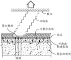
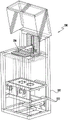
FIG. 1 is a schematic diagram of one embodiment of a method and apparatus for practicing the present invention wherein two precursor resins are mixed to produce a polymerizable liquid.
Figure 2 is a schematic representation of one embodiment of the process of the present invention.
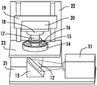
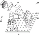
Fig. 3 is a perspective view of one embodiment of the device of the present invention.
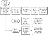
FIG. 4 is a first flowchart illustrating a control system and method for implementing the present invention.
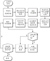
FIG. 5 is a second flowchart illustrating a control system and method for implementing the present invention.
FIG. 6 is a third flowchart illustrating a control system and method for implementing the present invention.
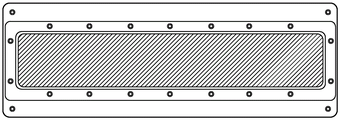
Fig. 7 is a top view of a 3 inch x 16 inch "high aspect ratio" rectangular build plate (or "window") assembly of the present invention with film dimensions of 3.5 inch x 17 inch.
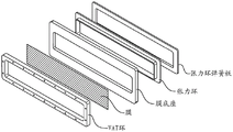
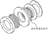
Fig. 8 is an exploded view of the build plate of fig. 7 showing a tension ring and a tension ring spring plate.
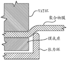
Fig. 9 is a side cross-sectional view of the build plate of fig. 7 and 10 showing how the tensioning members tension and secure the polymer film.
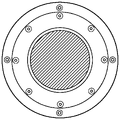
Fig. 10 is a top view of a 2.88 inch diameter circular build plate of the present invention where the membrane size can be 4 inches in diameter.
Fig. 11 is an exploded view of the build plate of fig. 10.
Fig. 12 shows various alternative embodiments of the build plate of fig. 7-11.
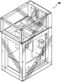
Fig. 13 is a front perspective view of an apparatus according to an exemplary embodiment of the present invention.
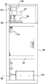
Fig. 14 is a side view of the device of fig. 13.
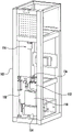
Fig. 15 is a rear perspective view of the device of fig. 13.
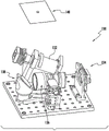
Fig. 16 is a perspective view of a light engine assembly for use with the device of fig. 13.
Fig. 17 is a front perspective view of an apparatus according to another exemplary embodiment of the present invention.
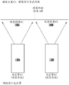
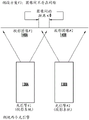
Fig. 18A is a schematic diagram illustrating a tiled image (tiled images).
Fig. 18B is a second schematic diagram illustrating a laid-out image.
Fig. 18C is a third schematic view illustrating a laid-out image.
Fig. 19 is a front perspective view of an apparatus according to another exemplary embodiment of the present invention.
Fig. 20 is a side view of the device of fig. 19.
Fig. 21 is a perspective view of a light engine assembly for use with the device of fig. 19.
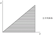
Figure 22 is an illustration of the method of the present invention showing the position of the carrier relative to the build surface or plate, wherein both advancement of the carrier and irradiation of the build area occur in succession. The advancement of the carrier is illustrated on the vertical axis and the time is illustrated on the horizontal axis.
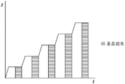
FIG. 23 is an illustration of another method of the present invention showing the position of the carrier relative to the build surface or plate, wherein both advancement of the carrier and irradiation of the build area are performed in steps, but with dead zones and gradients of polymerization maintained. The advancement of the carrier is still illustrated on the vertical axis and the time on the horizontal axis.
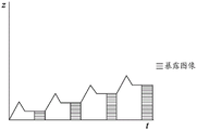
FIG. 24 is an illustration of yet another method of the present invention showing the position of the carrier relative to the build surface or plate, wherein both advancement of the carrier and irradiation of the build region are performed in steps, maintaining a dead zone and gradient of polymerization, and introducing a reciprocating step between the irradiation steps to enhance the flow of polymerizable liquid into the build region. The advancement of the carrier is still illustrated on the vertical axis and the time on the horizontal axis.
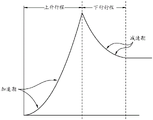
Fig. 25 is a detailed illustration of the reciprocation step of fig. 24, showing an acceleration period existing in the upstroke (i.e., a gradual start of the upstroke) and a deceleration period existing in the downstroke (i.e., a gradual end of the downstroke).
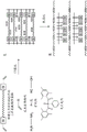
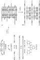
Fig. 26A depicts a dual cure system using thermally cleavable end groups. I. A crosslinked blocked diisocyanate prepolymer containing unreacted chain extender. A polymer blend of i) a linear ethylenically unsaturated blocking monomer copolymerized with a reactive diluent and ii) a linear thermoplastic polyurethane.
FIG. 26B depicts the process of the present invention performed with methacrylate blocked diisocyanates (ABDIs). I. A crosslinked blocked diisocyanate containing unreacted soft segment and a chain extender. A polymer blend of i) a linear ethylenically unsaturated blocking monomer copolymerized with a reactive diluent and ii) a linear thermoplastic polyurethane.
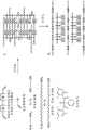
Fig. 26C depicts the process of the present invention performed with (meth) Acrylate Blocked Chain Extenders (ABCEs). I. A crosslinked blocked diisocyanate containing a chain extender containing unreacted soft segments and a chain extender. A polymer blend of i) a linear ethylenically unsaturated blocking monomer copolymerized with a reactive diluent and ii) a linear thermoplastic polyurethane.
Detailed description of illustrative embodiments
The present invention now will be described more fully hereinafter with reference to the accompanying drawings, in which embodiments of the invention are shown. This invention may, however, be embodied in many different forms and should not be construed as limited to the embodiments set forth herein; rather, these embodiments are provided so that this disclosure will be thorough and complete, and will fully convey the scope of the invention to those skilled in the art.
Like numbers refer to like elements throughout. In the drawings, the thickness of some lines, layers, components, elements or features may be exaggerated for clarity. Dashed lines indicate optional features or operations where used, unless otherwise specified.
The terminology used herein is for the purpose of describing particular embodiments only and is not intended to be limiting of the invention. As used herein, the singular forms "a", "an" and "the" are intended to include the plural forms as well, unless the context clearly indicates otherwise. It will be further understood that the terms "comprises" and/or "comprising," when used in this specification, specify the presence of stated features, integers, steps, operations, elements, components, and/or groups, or combinations thereof, but do not preclude the presence or addition of one or more other features, integers, steps, operations, elements, components, and/or groups, or combinations thereof.
As used herein, the term "and/or" includes any and all possible combinations of one or more of the associated listed items, as well as the absence of a combination when interpreted in the alternative (or).
Unless otherwise defined, all terms (including technical and scientific terms) used herein have the same meaning as commonly understood by one of ordinary skill in the art to which this invention belongs. It will be further understood that terms, such as those defined in commonly used dictionaries, should be interpreted as having a meaning that is consistent with their meaning in the context of the specification and claims and should not be interpreted in an idealized or overly formal sense unless expressly so defined herein. Well-known functions or constructions may not be described in detail for brevity and/or clarity.
It will be understood that when an element is referred to as being "on," "attached to," "connected to," combined with, "contacting" another element, etc., it can be directly on, attached to, connected to, combined with, and/or contacting the other element or intervening elements may also be present. In contrast, when an element is referred to as being "directly on," "directly attached to," directly connected to, "directly engaged with" or "directly contacting" another element, there are no intervening elements present. One skilled in the art will also appreciate that a structure or member that is referred to as being disposed "adjacent" another member may have portions that overlie or underlie the adjacent member.
Spatially relative terms, such as "below," "lower," "above," "upper," and the like, may be used herein for ease of description to describe an element or component's relationship to another element or component as illustrated in the figures. It will be understood that the spatially relative terms are intended to encompass different orientations of the device in use or operation in addition to the orientation depicted in the figures. For example, if the device in the figures is turned over, elements described as "below" or "beneath" other elements or features would then be oriented "above" the other elements or features. Thus, the exemplary term "below" can include both an orientation of above and below. The device may be otherwise oriented (rotated 90 degrees or at other orientations) and the spatially relative descriptors used herein interpreted accordingly. Similarly, the terms "upward," "downward," "vertical," "horizontal," and the like are used herein for illustrative purposes only, unless explicitly indicated otherwise.
It will be understood that, although the terms first, second, etc. may be used herein to describe various elements, components, regions, layers and/or sections, these elements, components, regions, layers and/or sections should not be limited by these terms. Rather, these terms are only used to distinguish one element, component, region, layer and/or section from another element, component, region, layer and/or section. Thus, a first element, component, region, layer or section discussed herein could be termed a second element, component, region, layer or section without departing from the teachings of the present invention. The order of operations (or steps) is not limited to the order presented in the claims or figures unless specifically indicated otherwise.
The "shape to be imparted." refers to the case where the shape of the intermediate changes slightly between its formation and the formation of the subsequent three-dimensional product, typically by shrinking (e.g., up to 1, 2, or 4 vol%), expanding (e.g., up to 1, 2, or 4 vol%), removing the carrier structure, or by an insert shaping step (e.g., intentionally bending, stretching, drilling, grinding, cutting, polishing, or other intentional shaping after the intermediate product is formed but before the subsequent three-dimensional product is formed). As noted above, the three-dimensional intermediate may also be washed, if desired, before further curing and/or before, during or after any intervening shaping steps.
As used herein, "hydrocarbyl" refers to difunctional hydrocarbyl that may be aliphatic, aromatic, or a mixture of aliphatic and aromatic, and optionally contains one or more (e.g., 1, 2, 3, or 4) heteroatoms (typically selected from N, O and S). Such hydrocarbyl groups may be optionally substituted (e.g., with additional isocyanate groups) and may contain 1, 2, or 3 carbon atoms, up to 6, 8, or 10 carbon atoms or more, and up to 40, 80, or 100 carbon atoms or more.
As used herein, "hard segment" and "soft segment" are derived from the morphology of elastomeric polymers that may contain distinct phase separated regions. These regions can be detected by thermal analysis techniques and distinguished by, for example, glass transition temperature. In general, the soft segments of a polymer can be considered to have a glass transition temperature below room temperature, while the hard segments can be considered to have a glass transition temperature above room temperature, or even a melting point if microcrystalline. The present view (and their classification) shows that the "soft segment" prepolymer or resin component is associated with the formation of the soft segment of the product, whereas the hard segment prepolymer or resin component is associated with the hard segment of the product. The structure-property relationships of hard and soft segment phases are described, for example, by Redman in "Developments in Polyurethanes-I" J.M. Buist Ed., Elsevier, London- -1978. See, for example, U.S. patent No. 5,418,259 (Dow).
The heating may be active heating (e.g., in an oven such as an electric, gas, or solar oven) or passive heating (e.g., at ambient temperature). Active heating is generally faster than passive heating and is preferred in some embodiments, but passive heating is preferred in some embodiments-e.g., simply maintaining the intermediate at ambient temperature for a sufficient time to effect further curing.
As used herein, "isocyanate" includes diisocyanates, polyisocyanates, and branched isocyanates.
"diisocyanate" and "polyisocyanate" are used interchangeably herein and refer to aliphatic, cycloaliphatic and aromatic isocyanates having an average of at least 2, or in some embodiments more than 2, isocyanate (NCO) groups per molecule. In some embodiments, the isocyanate has an average of 2.1, 2.3, 2.5, 2.8, or 3 isocyanate groups per molecule and an average of up to 6, 8, or 10 or more isocyanate groups per molecule. In some embodiments, the isocyanate may be a hyperbranched or dendritic isocyanate (e.g., containing more than 10 isocyanate groups per molecule on average, and up to 100 or 200 or more isocyanate groups per molecule on average). Common examples of suitable isocyanates include, but are not limited to, methylene diphenyl diisocyanate (MDI), Toluene Diisocyanate (TDI)), p-phenyl diisocyanate (PPDI), 4,4' -dicyclohexylmethane diisocyanate (HMDI), hexamethylene diisocyanate HDI), isophorone diisocyanate (IPDI), triphenylmethane-4, 4,4 "-triisocyanate, toluene-2, 4, 6-triyl triisocyanate, 1,3, 5-triazine-2, 4, 6-triisocyanate, ethyl ester L-lysine triisocyanate, and the like, including combinations thereof. Many additional examples are known and described in, for example, U.S. patent 9,200,108; 8,378,053, respectively; 7,144,955, respectively; 4,075,151, 3,932,342, and U.S. patent application publication nos. US 20040067318 and US 20140371406, the entire contents of which are incorporated herein by reference in their entirety.
"branched isocyanate" as used herein refers to a diisocyanate or polyisocyanate as described above having an average of 3 or more isocyanate groups per molecule or (for a mixture of different isocyanates) more than 2 isocyanate groups per molecule. In some embodiments, the branched isocyanate has an average of 2.1, 2.3, 2.5, 2.8, or 3 isocyanate groups per molecule and an average of up to 6, 8, or 10 or more isocyanate groups per molecule. In some embodiments, the isocyanate may be a hyperbranched or dendritic isocyanate as discussed above (e.g., containing an average of more than 10 isocyanate groups per molecule and an average of up to 100 or 200 or more isocyanate groups per molecule).
Oxidizable tin salts useful in the practice of the present invention include, but are not limited to, stannous butyrate, stannous octoate, stannous hexanoate, stannous heptanoate, stannous linoleate, stannous phenylbutyrate, phenylstannous stearate, phenylstannous oleate, stannous nonanoate, stannous decanoate, stannous undecanoate, stannous dodecanoate, stannous stearate, stannous oleate, stannous undecylenate, stannous 2-ethylhexanoate, dibutyltin dilaurate, dibutyltin dioleate, dibutyltin distearate, dipropyltin dilaurate, dipropyltin dioleate, dipropyltin distearate, dibutyltin dihexanoate, and combinations thereof. . See also U.S. patent nos. 5,298,532; 4,421,822, respectively; and 4,389,514, the disclosures of which are incorporated herein by reference. In addition to the oxidizable tin salts described above, Lewis acids such as those described in Chu et al, Macromolecular Symposia, 6.1995, volume 95, phase 1, page 233-242, are known to increase the polymerization rate of free radical polymerization and are incorporated herein by reference.
Any suitable filler may be used in conjunction with the present invention depending on the desired properties of the part or object to be manufactured. Thus, the filler may be solid or liquid, organic or inorganic, and may include reactive and non-reactive rubbers: silicone, acrylonitrile-butadiene rubber; reactive and non-reactive thermoplastics (including, but not limited to, poly (etherimides), maleimide-styrene terpolymers, polyarylates, polysulfones, polyethersulfones, and the like), inorganic fillers such as silicates (e.g., talc, clays, silica, mica), glass, carbon nanotubes, graphene, cellulose nanocrystals, and the like, including combinations of all of the foregoing. Suitable fillers include toughening agents, such as core-shell rubbers, as described below.
A toughening agent. One or more polymeric and/or inorganic tougheners may be used as fillers in the present invention. See generally U.S. patent application publication No. 20150215430. The toughening agent may be uniformly distributed in the form of particles in the cured product. The particles may be less than 5 micrometers (μm) in diameter. These toughening agents include, but are not limited to, those formed from: elastomers, branched polymers, hyperbranched polymers, dendrimers, rubbery polymers, rubbery copolymers, block copolymers, core-shell particles, oxides or inorganic materials such as clays, polyhedral oligomeric silsesquioxanes (POSS), carbonaceous materials (e.g., carbon black, carbon nanotubes, carbon nanofibers, fullerenes), ceramics and silicon carbide, with or without surface modification or functionalization. Examples of block copolymers include copolymers whose composition is described in U.S. Pat. No. 6,894,113 (Coart et al, Atofina, 2005) and include "NANOSTRENTH" SBM (polystyrene-polybutadiene-polymethacrylate) and AMA (polymethacrylate-polybutylacrylate-polymethacrylate) produced by Arkema. Other suitable block copolymers include FORTEGRA TMAnd amphiphilic block copolymers described in U.S. Pat. No. 7,820,760B2 assigned to Dow Chemical. Examples of known core-shell particles include core-shell (dendrimer) particles for amine branched polymers whose composition is described in US20100280151a1(Nguyen et al, Toray Industries, inc., 2010), as a shell grafted onto a core polymer polymerized from a polymerizable monomer containing unsaturated carbon-carbon bonds, core-shell rubber particles whose composition is described in EP1632533a1 and EP 2123711a1 of Kaneka Corporation, and "KaneAce M of said particle/epoxy blend whose particles have a polymeric coreX "lines, the polymeric core being polymerized from polymerizable monomers such as butadiene, styrene, other unsaturated carbon-carbon bond monomers, or combinations thereof, and a polymeric shell compatible with epoxy resins (typically polymethylmethacrylate, polyglycidyl methacrylate, polyacrylonitrile, or similar polymers), as discussed further below. Also suitable as block copolymers of the present invention are: the "JSR SX" series of carboxylated polystyrene/polydivinylbenzenes manufactured by JSR corporation; "Kureha Paraloid" EXL-2655 (produced by Kureha Chemical Industry Co., Ltd.) as a butadiene alkyl methacrylate styrene copolymer; "Stafiloid" AC-3355 and TR-2122 (both produced by Takeda Chemical Industries, Ltd.), each of which is an acrylate methacrylate copolymer; and "PARALOID" EXL-2611 and EXL-3387 (both produced by Rohm & Haas), each of which is a butyl acrylate methyl methacrylate copolymer. Examples of suitable oxide particles include NANOPOX ® produced by nanoresins AG. This is the main blend of functionalized nano silica particles and epoxy resin.
Core-shell rubber. Core-shell rubber is a particulate material (particle) having a rubber core. Such materials are known and described, for example, in U.S. patent application publication No. 20150184039, as well as U.S. patent application publication No. 20150240113 and U.S. patent nos. 6,861,475, 7,625,977, 7,642,316, 8,088,245, and elsewhere.
In some embodiments, the core-shell rubber particles are nanoparticles (i.e., have an average particle size of less than 1000 nanometers (nm)). Typically, the average particle size of the core-shell rubber nanoparticles is less than 500nm, such as less than 300nm, less than 200nm, less than 100nm or even less than 50 nm. Typically, such particles are spherical, so the particle size is the diameter; however, if the particles are not spherical, the particle size is defined as the longest dimension of the particle.
In some embodiments, the glass transition temperature (Tg) of the rubber core may be less than-25 deg.C, more preferably less than-50 deg.C, and even more preferably less than-70 deg.C. The Tg of the rubber core may be much lower than-100 ℃. The core-shell rubber also has at least one shell portion, which preferably has a Tg of at least 50 ℃. "core" refers to the inner portion of the core-shell rubber. The core may form the center of the core-shell particle, or the inner shell or domain of the core-shell rubber. The shell is a portion of the core-shell rubber outside of the rubber core. The shell portion(s) typically form the outermost portion of the core-shell rubber particle. The shell material may be grafted onto the core or crosslinked. The rubber core may comprise 50-95%, or 60-90% by weight of the core-shell rubber particles.
The core of the core-shell rubber may be a polymer or copolymer of a conjugated diene, such as butadiene, or a lower alkyl acrylate, such as n-butyl-, ethyl-, isobutyl-or 2-ethylhexyl acrylate. The core polymer may additionally contain up to 20% by weight of other copolymerized monounsaturated monomers, such as styrene, vinyl acetate, vinyl chloride, methyl methacrylate, etc. The core polymer is optionally crosslinked. The core polymer optionally contains up to 5% of a copolymerized graft link monomer having two or more sites of unsaturation of unequal reactivity, such as diallyl maleate, monoallyl fumarate, allyl methacrylate, and the like, at least one of the reactive sites being non-conjugated.
The core polymer may also be silicone rubber. These materials typically have a glass transition temperature below-100 ℃. Core-shell rubbers having a silicone rubber core include those commercially available under the trade designation GENIOPERL ® from Wacker Chemie, Munich, Germany.
The shell polymer, optionally chemically grafted or crosslinked to the rubber core, may be polymerized from at least one lower alkyl methacrylate such as methyl methacrylate, ethyl methacrylate or t-butyl methacrylate. Homopolymers of such methacrylate monomers may be used. In addition, up to 40% by weight of the shell polymer may be formed from other monovinylidene monomers such as styrene, vinyl acetate, vinyl chloride, methyl acrylate, ethyl acrylate, butyl acrylate, and the like. The molecular weight of the graft shell polymer may be between 20,000 and 500,000.
One suitable type of core-shell rubber has reactive groups in the shell polymer that can react with the epoxy resin or epoxy resin hardener. Glycidyl groups are suitable. These may be provided by monomers such as glycidyl methacrylate.
One example of a suitable core-shell rubber is of the type described in U.S. patent application publication No. 2007/0027233(EP 1632533 a 1). The core-shell rubber particles described therein comprise a crosslinked rubber core, in most cases a crosslinked copolymer of butadiene, and a shell, which is preferably a copolymer of styrene, methyl methacrylate, glycidyl methacrylate and optionally acrylonitrile. The core-shell rubber is preferably dispersed in a polymer or epoxy resin, as also described in this document.
Suitable core-shell rubbers include, but are not limited to, those sold under the name Kaneka Kane Ace by Kaneka Corporation, including the Kaneka Kane Ace15 and 120 series of products including Kaneka Kane Ace MX 120, Kaneka Kane Ace MX 153, Kaneka Kane Ace MX 154, Kaneka Kane Ace MX 156, Kaneka Kane Ace MX170 and Kaneka Kane Ace MX 257 and Kaneka Kane Ace MX 120 core-shell rubber dispersions and mixtures thereof.
I. Polymerizable liquid part A.
The dual cure system described herein can comprise a first curable system (sometimes referred to herein as "part a") that is curable by actinic radiation, typically light, in some embodiments Ultraviolet (UV) light. Any suitable polymerizable liquid may be used as the first component. The liquid (also sometimes referred to herein as a "liquid resin", "ink", or simply "resin") may include monomers, particularly photopolymerizable and/or free radically polymerizable monomers, and suitable initiators, such as free radical initiators, and combinations thereof. Examples include, but are not limited to, acrylic resins, methacrylic resins, acrylamides, styrenics, olefins, halogenated olefins, cyclic olefins, maleic anhydride, alkenes, alkynes, carbon monoxide, functionalized oligomers, multifunctional cure site (cut site) monomers, functionalized PEGs, and the like, including combinations thereof. Examples of liquid resins, monomers, and initiators include, but are not limited to, U.S. patent nos. 8,232,043; 8,119,214, respectively; 7,935,476, respectively; 7,767,728, respectively; 7,649,029, respectively; WO 2012129968 a 1; CN 102715751A; those set forth in JP 2012210408A.
An acid catalyzed polymerizable liquid. While in some embodiments as described above the polymerizable liquid comprises a free radically polymerizable liquid (in which case the inhibitor may be oxygen as described below), in other embodiments the polymerizable liquid comprises an acid catalyzed or cationically polymerizable liquid. In such embodiments the polymerizable liquid comprises monomers containing groups suitable for acid catalysis, such as epoxy groups, vinyl ether groups, and the like. Suitable monomers therefore include olefins such as methoxyethylene, 4-methoxystyrene, styrene, 2-methylpropan-1-ene, 1, 3-butadiene, and the like; heterocyclic monomers (including lactones, lactams, and cyclic amines) such as oxirane, thiabutadine, tetrahydrofuran, oxazoline, 1, 3-dioxepane, oxetan-2-one, and the like, and combinations thereof. Suitable (typically ionic or non-ionic) photoacid generators (PAGs) are included in the acid-catalyzed polymerizable liquid, examples of which include, but are not limited to, onium salts, sulfonium and iodonium salts and the like, such as diphenyliodonium hexafluorophosphate, diphenyliodonium hexafluoroarsenate, diphenyliodonium hexafluoroantimonate, diphenylp-methoxyphenyl trifluoromethanesulfonate, diphenylp-benzylidene trifluoromethanesulfonate, diphenylp-isobutylphenyl trifluoromethanesulfonate, diphenylp-tert-butylphenyl trifluoromethanesulfonate, triphenylsulfonium hexafluorophosphate, triphenylsulfonium hexafluoroarsenate, triphenylsulfonium hexafluoroantimonate, triphenylsulfonium trifluoromethanesulfonate, dibutylnaphthylsulfonium trifluoromethanesulfonate and the like, including mixtures thereof. See, e.g., U.S. patent nos. 7,824,839; 7,550,246; 7,534,844; 6,692,891, respectively; 5,374,500, respectively; and 5,017,461; see also Photoacid Generator Selection Guide for the electronics industry and energy curable coatings (BASF 2010)。
A hydrogel.In some embodiments, suitable resins include photo-curable hydrogels, such as poly (ethylene glycol) (PEG) and gelatin. PEG hydrogels have been used to deliver a variety of biologics, including growth factors; however, one of the challenges facing PEG hydrogels crosslinked by chain-growth polymerization is the potential for irreversible protein damage. Enhanced conjugation of PEG from photopolymerization by adding affinity-binding peptide sequences to a monomer resin solution prior to photopolymerizationConditions in the diacrylate hydrogel to maximize release of the biologic for sustained delivery. Gelatin is a common biopolymer used in the food, cosmetic, pharmaceutical and photographic industries. It is obtained by thermal denaturation or chemical and physical degradation of collagen. There are three types of gelatin, including those found in animals, fish, and humans. Gelatin from cold water fish skin is considered safe for use in pharmaceutical applications. UV or visible light can be used to crosslink suitably modified gelatin. The method of crosslinking gelatin involves curing a derivative from a dye such as rose bengal.
A photocurable polysiloxane resin.Suitable resins include photocurable polysiloxanes. UV-curable Silicone rubbers, such as Siliopren ™ UV Cure Silicone Rubber rubbers, may be used, as well as LOCTITE ™ Cure Silicone adhesive sealants. Applications include optical instruments, medical and surgical equipment, outdoor lighting and housings, electrical connectors/sensors, optical fibers, gaskets, and molds.
A biodegradable resin.Biodegradable resins are particularly important for implantable devices for drug delivery or for temporary functional applications such as biodegradable screws and stents (U.S. Pat. Nos. 7,919,162; 6,932,930). Biodegradable copolymers of lactic and glycolic acid (PLGA) can be dissolved in PEG di (meth) acrylate to produce useful transparent resins. Polycaprolactone and PLGA oligomers can be functionalized with acrylic or methacrylic groups to make them effective resins for use.
A photocurable polyurethane.Particularly useful resins are photocurable polyurethanes (including polyureas, and copolymers of polyurethanes and polyureas (e.g., poly (urethane-urea)). photopolymerizable polyurethane/polyurea compositions can be formulated that include (1) a polyurethane based on an aliphatic diisocyanate, poly (hexamethylene isophthalate), and optionally 1, 4-butanediol, (2) a multifunctional acrylate, (3) a photoinitiator, and (4) an antioxidant such that they provide a hard, abrasion and stain resistant material (U.S. patent 4,337,130) Alcohol is used as a chain extender.
A high performance resin.In some embodiments, a high performance resin is used. As noted above and discussed further below, such high performance resins may sometimes require the use of heat to melt and/or reduce their viscosity. Examples of such resins include, but are not limited to, resins such as those described in U.S. Pat. nos. 7,507,784; 6,939,940 for those materials sometimes referred to as liquid crystal polymers of ester, ester-imide, and ester-amide oligomers. Since such resins are sometimes used as high temperature thermoset resins, as discussed further below, they further comprise suitable photoinitiators in the present invention, such as benzophenone, anthraquinone, and fluorenone (including derivatives thereof) initiators to initiate crosslinking upon irradiation.
Additional example resins.Resins particularly useful for dental applications include EnvisionTEC's Clear Guide, EnvisionTEC's E-Denstone Material. Resins particularly useful in the hearing aid industry include EnvisionTEC's e-Shell 300 Series resins. Particularly useful resins include EnvisionTEC's HTM140IV High Temperature Mold Material used directly with vulcanized rubber for molding/casting applications. Materials particularly useful for fabricating ductile and rigid components include EnvisionTEC's RC31 resin. Resins particularly useful for investment casting applications include EnvisionTEC's Easy Cast EC500 resins and madesoid fireacat resins.
A resin component is added.The liquid resin or polymerizable material may have solid particles suspended or dispersed therein. Any suitable solid particles may be used depending on the final product being manufactured. The particles may be metallic, organic/polymeric, inorganic or composite materials or mixtures thereof. The particles may be non-conductive, semi-conductive, or conductive (including metallic and non-metallic or polymeric conductors); the particles may be magnetic, ferromagnetic, paramagnetic or non-magnetic. The particles can have any suitable shape, including spherical, ellipsoidal, cylindrical, and the like. The particles can have any suitable size (e.g., 1 nanometer to 20 micrometers average diameter).
The particles may comprise active agents or detectable compounds as described below, although these may also be provided dissolved in the liquid resin as described below. For example, magnetic or paramagnetic particles or nanoparticles may be used.
The liquid resin may have additional ingredients dissolved therein, including pigments, dyes, active or pharmaceutical compounds, detectable compounds (e.g., fluorescent, phosphorescent, radioactive), etc., again depending on the particular purpose of the product being manufactured. Examples of such additional components include, but are not limited to, proteins, peptides, nucleic acids (DNA, RNA) such as siRNA, sugars, small organic compounds (drugs and drug-like compounds), and the like, including combinations thereof.
A non-reactive light absorber.In some embodiments, the polymerizable liquid used in the practice of the present invention comprises a non-reactive pigment or dye that absorbs light, particularly ultraviolet light. Suitable examples of such light absorbers include, but are not limited to:(i) titanium dioxide (for example contained in an amount of 0.05 or 0.1 to 1 or 5% by weight),(ii)carbon black (e.g., included in an amount of 0.05 or 0.1 to 1 or 5 wt.%), and/or(iii) Organic uv light absorbers, such as hydroxybenzophenones, hydroxyphenyl benzotriazoles, oxanilides, benzophenones, thioxanthones, hydroxyphenyl triazines and/or benzotriazole uv light absorbers (e.g., Mayzo BLS1326) (e.g., included in amounts of 0.001 or 0.005 to 1, 2 or 4 weight percent). Examples of suitable organic uv absorbers include, but are not limited to, U.S. patent nos. 3,213,058; 6,916,867, respectively; 7,157,586, respectively; and 7,695, 643, the disclosures of which are incorporated herein by reference.
A polymerization inhibitor.The inhibitor or polymerization inhibitor used in the present invention may be in liquid or gaseous form. In some embodiments, gas suppressants are preferred. In some embodiments, a liquid inhibitor, such as an oil or lubricant (e.g., a fluorinated oil such as a perfluoropolyether), can be used as the inhibitor (or as a release layer to maintain a liquid interface). The specific inhibitor will depend on the monomer being polymerized and the polymerization reaction. For free radical polymerization monomers, the inhibitor may conveniently be oxygen, which may be provided in gaseous form, such as air, oxygen-enriched gas (optionally but in some embodiments) Preferably with an additional inert gas to reduce its flammability) or in some embodiments pure oxygen. In alternative embodiments, for example where the monomers are polymerized by a photoacid generator initiator, the inhibitor may be a base such as ammonia, trace amines (e.g., methylamine, ethylamine, di-and trialkylamines such as dimethylamine, diethylamine, trimethylamine, triethylamine, etc.) or carbon dioxide, including mixtures or combinations thereof.
Polymerizable liquid with living cells.In some embodiments, the polymerizable liquid may have living cells as "particles" therein. Such polymerizable liquids are typically aqueous and can be oxygenated and can be considered as "emulsions" when the living cells are in a discrete phase. Suitable living cells can be plant cells (e.g., monocots, dicots), animal cells (e.g., mammalian, poultry, amphibian, reptile cells), microbial cells (e.g., prokaryotes, eukaryotes, protozoa, etc.), and the like. The cells may have differentiated cells from or correspond to any type of tissue (e.g., blood, cartilage, bone, muscle, endocrine glands, exocrine glands, epithelium, endothelium, etc.), or may be undifferentiated cells, such as stem cells or progenitor cells. In such embodiments, the polymerizable liquid may be a hydrogel-forming liquid, including, but not limited to, U.S. patent nos. 7,651,683; 7,651,682, respectively; 7,556,490, respectively; 6,602,975, respectively; 5,836,313, respectively; and the like.
II. device
One non-limiting embodiment of the apparatus of the present invention is shown in fig. 3. It contains a radiation source 11, such as a Digital Light Processor (DLP), which provides electromagnetic radiation 12 which irradiates a build chamber defined by walls 14 and a rigid or flexible build plate 15 forming the bottom of the build chamber via a mirror 13, which build chamber is filled with a liquid resin 16. The chamber bottom 15 is constructed of a build plate that includes a rigid or flexible semipermeable member as discussed further below. The top of the object 17 under construction is attached to a carrier 18. The carrier is driven in a vertical direction by a linear stage 19, although alternative configurations may be used as described below.
A liquid resin reservoir, tubing, pump, level sensor, and/or valve may be included to supplement a pool of liquid resin in the build chamber (not shown for clarity), although in some embodiments simple gravity feed may be used. The drives/actuators and associated wiring (also not shown for clarity) of the carrier or linear stage may be included according to known techniques. The driver/actuator, radiation source and in some embodiments the pump and level sensor may all be operatively associated with a suitable controller, again in accordance with known techniques.
The build plate 15 used in the practice of the present invention typically comprises or is constructed of a (typically rigid or solid, stationary, and/or fixed, although in some embodiments flexible) semi-permeable (or gas permeable) member, alone or in combination with one or more additional support substrates (e.g., clamps and tensioning members to tension and stabilize otherwise flexible semi-permeable material). The semipermeable member can be made of any suitable material that is optically transparent at the relevant wavelength (or otherwise transparent to the radiation source, whether or not it is perceived by the human eye as being optically transparent-i.e., the optically transparent window can be, in some embodiments, optically opaque), including, but not limited to, porous or microporous glass and rigid gas permeable polymers used to make rigid gas permeable contact lenses.Ginseng radix See, for exampleNorman g, Gaylord, U.S. patent No. RE31,406; see also U.S. patent nos. 7,862,176; 7,344,731, respectively; 7,097,302, respectively; 5,349,394, respectively; 5,310,571, respectively; 5,162,469, respectively; 5,141,665, respectively; 5,070,170, respectively; 4,923,906, respectively; and 4,845,089. In some embodiments, such materials are characterized as glassy and/or amorphous polymers and/or substantially crosslinked to render them substantially non-swellable. The semipermeable member is preferably formed from a material that does not swell (i.e., "non-swellable") upon contact with the liquid resin or material to be polymerized. Suitable materials for the semipermeable member include amorphous fluoropolymers such as those described in U.S. patent nos. 5,308,685 and 5,051,115. For example, such fluoropolymers are particularly advantageous over silicones that may swell when used with organic liquid resin inks to be polymerized. For some liquid resin inks, e.g. more In aqueous monomer systems and/or some polymeric resin ink systems with a low tendency to swell, silicone based window materials (window materials) may be suitable. The solubility or permeability of the organic liquid resin ink can be significantly reduced by a number of known parameters, including increasing the crosslink density of the window material or increasing the molecular weight of the liquid resin ink. In some embodiments, the build plate may be formed from a film or sheet of material that is flexible when detached from the device of the invention but is clamped and tensioned (e.g. with a tension ring) when installed in the device to cause it to be tensioned and secured in the device. Specific materials include TEFLON AF @ fluoropolymer commercially available from DuPont. Additional materials include, for example, U.S. patent nos. 8,268,446; 8,263,129; 8,158,728, respectively; and 7,435,495.
It will be appreciated that substantially all solid materials and most of the above have some inherent "flexibility", although they may be considered "rigid" depending on factors such as their shape and thickness and environmental factors such as the pressure and temperature to which they are subjected. Furthermore, the terms "stationary" or "fixed" with respect to the build plate are intended to mean that no mechanical interruption (mechanical interruption) of the method occurs, or no mechanism or structure is provided for mechanically interrupting the method (as in a layer-by-layer method or apparatus), even if a mechanism is provided for incrementally adjusting (incremental adjustment) the build plate (e.g., an adjustment that does not cause or cause gradient collapse of the polymerization zone).
The semipermeable member generally includes a top surface portion, a bottom surface portion, and an edge surface portion. The build surface is on the top portion; and the feed surface may be on one, two or all three of the top surface portion, the bottom surface portion and/or the edge surface portion. In the embodiment illustrated in fig. 3, the feeding surface is on a bottom portion, although alternative configurations may be implemented using conventional techniques, wherein the feeding surface is provided on an edge and/or on a top portion (adjacent to but spaced apart or apart from the build surface).
The semipermeable member has a thickness in some embodiments of 0.01, 0.1, or 1 millimeter to 10 or 100 millimeters or more (depending on the size of the object being manufactured, whether it is laminated to or in contact with an additional support plate, such as glass or the like, as discussed further below).
The permeability of the semipermeable member to the polymerization inhibitor will depend on conditions such as the pressure of the atmosphere and/or inhibitor, the choice of inhibitor, the rate or speed of manufacture, and the like. Generally, when the inhibitor is oxygen, the oxygen permeability of the semipermeable member can be from 10 or 20 Barrers to 1000 or 2000 Barrers or more. For example, a semipermeable member having a permeability of 10 Barrers for use with a pure oxygen or highly oxygen-enriched atmosphere at a pressure of 150 PSI may behave substantially the same as a semipermeable member having a permeability of 500 Barrers when oxygen is supplied from an ambient atmosphere at atmospheric conditions.
Thus, the semipermeable member can comprise a flexible polymeric membrane (having any suitable thickness, e.g., 0.001, 0.01, 0.05, 0.1, or 1 millimeter to 1, 5, 10, or 100 millimeters or more), and the build plate can further comprise a tensioning member (e.g., a peripheral clip and operatively associated strain member or tensile member, such as in a "drumhead"), a plurality of peripheral clips, and the like, including combinations thereof) attached to the polymeric membrane and securing and tensioning, stabilizing, or fixing the membrane (e.g., at least enough that the membrane will not adhere to the object when the object is advanced and rebounds or springs from the membrane). The membrane has a top surface and a bottom surface, the build surface being on the top surface and the feed surface preferably being on the bottom surface. In other embodiments, the semipermeable member comprises: (i) a polymeric film layer (of any suitable thickness, e.g., 0.001, 0.01, 0.1, or 1 millimeter to 5, 10, or 100 millimeters or more) having a top surface positioned for contact with a polymerizable liquid, and a bottom surface, and (ii) a gas-permeable, optically transparent support member (of any suitable thickness, e.g., 0.01, 0.1, or 1 millimeter to 10, 100, or 200 millimeters or more) contacting the bottom surface of the film layer. The support member has a top surface that contacts the bottom surface of the film layer, and the support member has a bottom surface that can act as a feed surface for the polymerization inhibitor. Any suitable semipermeable (i.e., permeable to the polymerization inhibitor) material may be used. For example, the polymer membrane or polymer membrane layer may be a fluoropolymer membrane, such as an amorphous thermoplastic fluoropolymer, such as a TEFLON AF 1600-or TEFLON AF 2400-fluoropolymer membrane, or a perfluoropolyether (PFPE), in particular a crosslinked PFPE membrane, or a crosslinked polysiloxane polymer membrane. The support member comprises a silicone or cross-linked silicone polymer member, such as a polydimethylsiloxane member, a gas-permeable polymer member, or a porous or microporous glass member. The membrane may be laminated or clamped directly to the rigid support member without an adhesive (e.g., using PFPE and PDMS materials), or a silane coupling agent that reacts with the upper surface of the PDMS layer may be used to adhere to the first polymer membrane layer. UV curable acrylate functional polysiloxanes may also be used as a tie layer between the UV curable PFPE and the rigid PDMS support layer.
When configured for placement in the apparatus, the carrier defines a "build region" on the build surface over the total area of the build surface. Since lateral "throw" (e.g., in the X and/or Y directions) is not required to break the adhesion between successive layers in the present invention, as in the Joyce and Chen devices mentioned above, the area of the build region within the build surface can be maximized (or conversely, the area of the build surface that does not serve as a build region can be minimized). Thus, in some embodiments, the total surface area of the build area can occupy at least 50%, 60%, 70%, 80%, or 90% of the total surface area of the build surface.
As shown in fig. 3, the various components are mounted on a support or frame assembly 20. Although the specific design of the support or frame assembly is not important and many configurations can be employed, in the illustrated embodiment it is comprised of a base 21 to which the radiation source 11 is fixedly or securely attached, a vertical member 22 to which the linear stage is operatively associated, and a horizontal table 23 to which the wall 14 is removably or securely attached (or on which the wall is placed), and permanently or removably secures the build plate to form a build chamber as described above.
As noted above, the build plate may be constructed of a single unitary and one-piece semipermeable member, or may contain additional materials. For example, porous or microporous glass may be laminated or otherwise secured to a semipermeable material. Alternatively, the semipermeable member, which is the upper portion, may be secured to a transparent lower member having purge channels formed therein for feeding polymerization inhibitor-laden gas into the semipermeable member through which it is conveyed to the build surface to facilitate formation of a release layer of unpolymerized liquid material as described above and below. Such purge passages may extend completely or partially through the floor: for example, the purge channel may extend partially into the floor, but then terminate in a region directly below the build surface to avoid introducing distortion. The specific geometry will depend on whether the feed surface of the inhibitor into the semipermeable member is on the same side of the build surface or on the opposite side, on an edge portion thereof, or a combination of several thereof.
Any suitable radiation source (or combination of radiation sources) may be used, depending on the particular resin used, including electron beam and ionizing radiation sources. In a preferred embodiment, the radiation source is a source of actinic radiation, such as one or more light sources, in particular one or more sources of ultraviolet light. Any suitable light source may be used, such as incandescent, fluorescent, phosphorescent or cold light lamps, lasers, light emitting diodes, and the like, including arrays thereof. As mentioned above, the light source preferably includes a patterning element (pattern-forming element) operatively associated with the controller. In some embodiments, the light source or patterning element comprises a digital (or Deformable) Micromirror Device (DMD) with Digital Light Processing (DLP), a spatial modulator (SLM) or micro-electromechanical system (MEMS) mirror array, a Liquid Crystal Display (LCD) panel, a mask (also known as a reticle), a silhouette (simple), or a combination thereof. See U.S. patent No. 7,902,526. The light source preferably comprises a spatial light modulating array, such as a liquid crystal light valve array or a micro-mirror array or DMD (e.g. having an operatively associated digital light processor, typically in turn under the control of a suitable controller), which is configured to maskless expose or irradiate the polymerizable liquid, e.g. by maskless lithography. See, e.g., theU.S. patent nos. 6,312,134; 6,248,509; 6,238,852; and 5,691,541.
In some embodiments, as discussed further below, the movement in the X and/or Y directions may be simultaneous with the movement in the Z direction, and the movement in the X and/or Y directions is therefore performed during the polymerization of the polymerizable liquid (this is different from the movement described in Y. Chen et al or m. Joyce above, which is the movement between previous and subsequent polymerization steps to replenish the polymerizable liquid). In the present invention, such movement may be performed, for example, to reduce "burn in" or fouling in specific areas of the build surface.
Since an advantage of some embodiments of the present invention is that the size of the build surface on the semipermeable member (i.e., the build plate or window) may be reduced because a large amount of lateral "throw" is not required as in the above-described Joyce or Chen device, in the methods, systems and apparatus of the present invention, the lateral movement of the carrier and object (including movement in the X and/or Y directions or combinations thereof), if any, is preferably no more than or less than 80, 70, 60, 50, 40, 30, 20 or even 10% of the width of the build area (in the direction of the lateral movement).
While in some embodiments the carrier is mounted on an elevator to advance up and away from a stationary build plate, in other embodiments the reverse arrangement may be used: that is, the carrier may be secured and the build plate lowered, thereby advancing the carrier away from the build plate. Many different mechanical configurations for achieving the same result will be apparent to those skilled in the art.
Depending on the choice of material used to make the carrier and the choice of polymer or resin used to make the article, the adhesion of the article to the carrier is sometimes insufficient to hold the article on the carrier until the finished product or "build" is complete. For example, aluminum supports may have lower adhesion than poly (vinyl chloride) (or "PVC") supports. One solution is therefore to use a support comprising PVC on the surface on which the manufactured article is polymerized. If this results in a too strong bond to conveniently separate the finished part from the carrier, the article may be further secured to the less tacky carrier using any of a variety of techniques, including but not limited to applying an adhesive Tape such as "Greener Masking Tape for Basic Painting #2025 High addition" to further secure the article to the carrier during the manufacturing process.
Controller and process control
The method and apparatus of the present invention may include process steps and apparatus components for implementing process control, including feedback and feed-forward control, to, for example, improve the speed and/or reliability of the method.
The controller for implementing the present invention may be implemented in the form of hardware circuitry, software, or a combination thereof. In one embodiment, the controller is a general purpose computer running software that is operatively associated with the monitor, drivers, pumps and other components through appropriate interface hardware and/or software. Software suitable for controlling the three-dimensional printing or manufacturing methods and apparatus as described herein includes, but is not limited to, ReplicatorG open source 3D printing programs, 3D P RInt ™ controller software from 3D systems, Slic3r, Skeinforge, KISSlicer, Repetier-Host, PrintRun, Cura, and the like, including combinations thereof.
Process parameters that are monitored directly or indirectly, continuously or intermittently, during the course of the method (e.g., during one, some, or all of the filling, irradiating, and advancing steps) include, but are not limited to, irradiation intensity, temperature of the carrier, polymerizable liquid in the build region, temperature of the growing product, temperature of the build plate, pressure, advancing speed, pressure, force (e.g., exerted on the build plate via the carrier and the product of manufacture), strain (e.g., exerted on the carrier by the growing product of manufacture), thickness of the release layer, and the like.
Known parameters that may be used in feedback and/or feedforward control systems include, but are not limited to, the expected consumption of the polymerizable liquid (e.g., based on a known geometry or volume of the article of manufacture), the degradation temperature of the polymer formed from the polymerizable liquid, and the like.
Process conditions that are controlled, directly or indirectly, in continuous or stepwise response to monitored parameters and/or known parameters (e.g., during any or all of the above process steps) include, but are not limited to, the supply rate of polymerizable liquid, temperature, pressure, rate or speed of advancement of the support, intensity of irradiation, duration of irradiation (e.g., for each "slice"), etc.
For example, the temperature of the polymerizable liquid in the build region or the temperature of the build plate can be monitored directly or indirectly with a suitable thermocouple, a non-contact temperature sensor (e.g., an infrared temperature sensor), or other suitable temperature sensor to determine whether the temperature exceeds the degradation temperature of the polymerized product. If so, the process parameters can be adjusted by the controller to reduce the temperature in the build area and/or the temperature of the build plate. Process parameters suitable for such adjustments may include: cooling with a cooler to reduce the temperature, reduce the rate of advancement of the carrier, reduce the intensity of the radiation, reduce the duration of radiation exposure, and the like.
In addition, the intensity of the irradiation source (e.g., an ultraviolet light source such as a mercury lamp) can be monitored with a photodetector to detect a decrease in intensity from the irradiation source (e.g., due to its conventional degradation during use). If detected, the process parameters can be adjusted by the controller to accommodate the loss of strength. Process parameters suitable for such adjustments may include: increasing the temperature with a heater, decreasing the rate of advancement of the carrier, increasing the power of the light source, etc.
As another example, control of temperature and/or pressure may be achieved with a heater and cooler (independently, or in conjunction with each other and separately in response to a controller) and/or with a pressure supply (e.g., a pump, a pressure vessel, a valve, or a combination thereof) and/or a pressure disengaging mechanism, such as a controllable valve (independently, or in conjunction with each other and separately in response to a controller), to increase manufacturing time.
In some embodiments, the controller is configured to maintain a gradient of polymerization zones as described herein throughout the manufacture of some or all of the final product (see, e.g., fig. 2). The particular configuration (e.g., time, rate or speed of advancement, radiation intensity, temperature, etc.) will depend on factors such as the particular polymerizable liquid and the nature of the product being produced. Configuration to maintain the gradient of the polymerization zone may be performed empirically by inputting a set of process parameters or instructions that are predetermined or determined through a series of trial runs or "trial and error"; the configuration may be provided by predetermined instructions; the configuration may be achieved by suitable monitoring and feedback (as discussed above), a combination thereof, or in any other suitable manner.
In some embodiments, the methods and apparatus described above may be controlled by a software program running on a general purpose computer with appropriate interface hardware between the computer and the apparatus. Many alternatives are commercially available. A non-limiting example of one combination of components is shown in fig. 4-6, where "Microcontroller" is a parallelx Propeller, the Stepper Motor Driver is a Sparkfun EasyDriver, the LED Driver is a Luxeon Single LED Driver, the USB Serial interface (USB TO Serial) is a parallelx USB Serial interface converter, and the DLP system is a Texas Instruments lightcraft system.
General methods
The three-dimensional intermediate is preferably formed from a resin as described above by additive manufacturing, typically bottom-up or top-down additive manufacturing. In general, top-down three-dimensional fabrication proceeds as follows:
(a) providing a polymerizable liquid reservoir having a polymerizable liquid fill level and a carrier located in the reservoir, the carrier and the fill level defining a build area therebetween;
(b) filling the build region with a polymerizable liquid (i.e., resin) comprising a mixture of: a dual cure system of (i) a light (typically ultraviolet) polymerizable liquid first component, and (ii) a second curable component; and then
(c) Irradiating the build region with light to form a solid polymer scaffold from the first component and also to advance the carrier away from the build surface to form a three-dimensional intermediate having the same shape as or to be imparted to the three-dimensional object and containing the second solidifiable component (e.g., a second reactive component) carried in the scaffold in an unsolidified or uncured form;
according to known techniques, a wiper blade, or an optically transparent (rigid or flexible) window may optionally be provided at the fill level to promote flattening of the polymerizable liquid. In the case of an optically transparent window, the window provides a build surface with respect to which a three-dimensional intermediate is formed, similar to the build surface in bottom-up three-dimensional fabrication discussed below.
In general, bottom-up three-dimensional fabrication proceeds as follows:
(a) providing a carrier and an optically transparent member having a build surface, the carrier and build surface defining a build area therebetween;
(b) filling the build region with a polymerizable liquid (i.e., resin) comprising a mixture of: a dual cure system of (i) a light (typically ultraviolet) polymerizable liquid first component and (ii) a second curable component; and then
(c) Irradiating the build region with light through the optically transparent member to form a solid polymeric scaffold from the first component and also advancing (typically raising) the carrier away from the build surface to form a three-dimensional intermediate having the same shape as or to be imparted to the three-dimensional object and containing the second solidifiable component (e.g., a second reactive component) carried in the scaffold in an unsolidified or uncured form.
In some embodiments of bottom-up or top-down three-dimensional fabrication performed in the context of the present invention, the build surface is stationary during formation of the three-dimensional intermediate; in other embodiments of bottom-up three-dimensional fabrication practiced in the context of the present invention, the build surface is tilted, slid, curved and/or peeled off, and/or otherwise displaced or released from the growing three-dimensional intermediate, typically repeatedly, during formation of the three-dimensional intermediate.
In some embodiments of bottom-up or top-down three-dimensional fabrication performed in the context of the present invention, the polymerizable liquid (or resin) is maintained in liquid contact with the growing three-dimensional intermediate and the build surface during some, most, or all of the process of fabricating the three-dimensional intermediate during the filling and irradiation steps.
In some embodiments of bottom-up or top-down three-dimensional fabrication performed in the context of the present invention, the growing three-dimensional intermediate is fabricated in a layer-free manner (e.g., actinic radiation or light patterned by multiple exposures or "tiles") during at least a portion of the formation of the three-dimensional intermediate.
In some embodiments of bottom-up or top-down three-dimensional fabrication performed in the context of the present invention, the growing three-dimensional intermediate is fabricated in a layer-by-layer manner (e.g., actinic radiation or light patterned by multiple exposures or "tiles") during at least a portion of the formation of the three-dimensional intermediate.
In some embodiments of bottom-up or top-down three-dimensional fabrication employing rigid or flexible optically transparent windows, a lubricant or immiscible liquid may be provided between the window and the polymerizable liquid (e.g., a fluorinated fluid or oil such as a perfluoropolyether oil).
It will be appreciated from the foregoing that in some embodiments of bottom-up or top-down three-dimensional fabrication carried out in the context of the present invention, a growing three-dimensional intermediate is fabricated in a layer-free manner during formation of at least a portion thereof and the same growing three-dimensional intermediate is fabricated in a layer-by-layer manner during formation of at least one other portion thereof. Thus, the mode of operation may be changed between layerless fabrication and layerwise fabrication one or more times as required by operating conditions such as part geometry.
In some embodiments, the intermediate is formed by Continuous Liquid Interface Preparation (CLIP), as discussed further below.
As noted above, the present invention provides (in some embodiments) a method of forming a three-dimensional object, comprising the steps of: (a) providing a carrier and a build plate, the build plate comprising a semipermeable member comprising a build surface and a feed surface separate from the build surface, wherein the build surface and the carrier define a build region therebetween, and wherein the feed surface is in fluid contact with a polymerization inhibitor; then (simultaneously and/or sequentially) (b) filling the build region with a polymerizable liquid, the polymerizable liquid contacting a build segment (c) irradiating the build region through the build plate to produce a polymerized solid region in the build region, wherein a liquid film release layer comprised of the polymerizable liquid is formed between the polymerized solid region and the build surface, polymerization of the liquid film being inhibited by a polymerization inhibitor; and (d) advancing the carrier with the polymerized region adhered thereto away from the build surface on the stationary build plate to create a subsequent build region between the polymerized region and the top zone (top zone). In general, the method comprises (e) continuing and/or repeating steps (b) through (d) to produce a subsequent polymerized area adhered to a previous polymerized area until continued or repeated deposition of polymerized areas adhered to each other forms a three-dimensional object.
The method may be performed in a continuous manner since no mechanical detachment of the release layer or no mechanical movement of the build surface to compensate for oxygen or other inhibitors is required, but it is to be appreciated that the individual steps described above may be performed sequentially, simultaneously, or a combination thereof. Indeed, the rate of the steps may be varied over time depending on factors such as the density and/or complexity of the regions in manufacture.
Furthermore, since mechanical detachment from the window or from the release layer typically requires the carrier to be advanced a distance from the build plate greater than that required for the next irradiation step (which can recoat the window) and then retracted closer to the build plate (e.g., a "two step forward one step" operation), the present invention can, in some embodiments, eliminate this "back-up" step and enable the carrier to be advanced in one direction or a single direction without intermediate movement of the window for recoating, or "snapping" a preformed resilient release layer. However, in other embodiments of the invention, a reciprocating movement is used, not to effect the detachment, but to more quickly fill or pump the polymerizable liquid into the build area.
Although there is no strict boundary between the dead zone and the gradient of the polymerization zone (in the location where the two meet), the thickness of the gradient of the polymerization zone is in some embodiments at least as great as the thickness of the dead zone. Thus, in some embodiments, the dead zone has a thickness of 0.01, 0.1, 1, 2, or 10 microns to 100, 200, or 400 microns or more, and/or the gradient of polymerization zones and dead zone together have a thickness of 1 or 2 microns to 400, 600, or 1000 microns or more. Thus, the gradient of the polymerization zone may be thick or thin, depending on the particular process conditions at the time. If the gradient of the polymerization zone is thin, it can also be described as an active surface on the bottom of the growing three-dimensional object with which the monomer can react and continue to form a growing polymer chain. In some embodiments, the gradient or active surface of the polymerization zone is maintained (while the polymerization step continues) for a period of at least 5, 10, 15, 20, or 30 seconds to 5, 10, 15, or 20 minutes or more, or until the three-dimensional product is completed.
The method can further include the step of interrupting the gradient of the polymerization zone for a time sufficient to form a cleavage line in the three-dimensional object (e.g., at a predetermined desired location to be intentionally cleaved, or at a location in the object where prevention of cleavage or reduction of cleavage is not important), and then resuming the gradient of the polymerization zone (e.g., by pausing and resuming the advancing step, increasing and then decreasing the irradiation intensity, and combinations thereof).
In some embodiments, the advancing step is performed sequentially in uniform increments (e.g., 0.1 or 1 micron to 10 or 100 microns or more) per step or increment. In some embodiments, the advancing step is performed sequentially in variable increments of each step or increment (e.g., each increment is 0.1 or 1 micron to 10 or 100 microns or more). The size of the increment, as well as the rate of advancement, will depend in part on factors such as temperature, pressure, and the structure (e.g., size, density, complexity, configuration, etc.) of the article being prepared.
In other embodiments of the present invention, the advancing step is performed continuously at a uniform or variable rate.
In some embodiments, the rate of advancement (whether sequential or continuous) is from about 0.1, 1, or 10 microns/second to about 100, 1,000, or 10,000 microns/second, again depending on factors such as temperature, pressure, structure of the article being made, radiation intensity, and the like.
As described further below, in some embodiments, the filling step is performed by forcing a polymerizable liquid under pressure into the build region. In such a case, one or more advancing steps may be performed at a rate or cumulative or average rate of at least 0.1, 1, 10, 50, 100, 500, or 1000 microns/second or more. In general, the pressure may be sufficient anyway to increase the rate of the one or more advancing steps by at least a factor of 2, 4, 6, 8, or 10 compared to the maximum repetition rate of the advancing steps in the absence of pressure. If the pressure is provided by enclosing the apparatus as described above in a pressure vessel and performing the method in a pressurized atmosphere (e.g., air, oxygen-enriched air, gas blend, pure oxygen, etc.), pressures of 10, 20, 30, or 40 pounds Per Square Inch (PSI) to 200, 300, 400, or 500 PSI or more may be used. To manufacture large irregular objects, higher pressures may not be preferred as slower manufacturing times due to the cost of large high pressure vessels. In such embodiments, the feed surface and polymerizable liquid may be in fluid contact with the same compressed gas (e.g., a compressed gas comprising 20 to 95 volume percent oxygen, which acts as a polymerization inhibitor).
On the other hand, when making smaller objects or making rods or fibers that can be taken or exited from the pressure vessel as it is made, through openings or holes in the pressure vessel, the size of the pressure vessel can be kept smaller than the size of the product being made and higher pressures can be used more easily (if desired).
As described above, the irradiation step is performed in some embodiments with patterned irradiation. Depending on the particular object being fabricated, this patterned irradiation may be a fixed pattern or may be a variable pattern generated by a pattern generator (e.g., DLP) as described above.
When the patterned irradiation is a variable pattern rather than a pattern that remains constant over time, each irradiation step may be of any suitable time or duration depending on factors such as the intensity of the irradiation, the presence or absence of dye in the polymerizable material, the growth rate, and the like. Thus, in some embodiments, the duration of each irradiation step may be from 0.001, 0.01, 0.1, 1, or 10 microseconds to 1, 10, or 100 minutes or more. The interval between the irradiation steps is preferably as short as possible in some embodiments, for example 0.001, 0.01, 0.1 or 1 microsecond to 0.1, 1 or 10 seconds. In exemplary embodiments, the pattern may change hundreds, thousands, or millions of times to impart shape changes to the formed three-dimensional object. Furthermore, in an exemplary embodiment, the pattern generator may have a high resolution, with millions of pixel elements (pixel elements) that may vary to change the shape it imparts. For example, the pattern generator may be a DLP with more than 1,000 or 2,000 or 3,000 or more rows and/or more than 1,000 or 2,000 or 3,000 or more columns of micro mirrors (or pixels in a liquid crystal panel), which may be used to change shape. In an exemplary embodiment, three-dimensional objects may be formed by a gradient of polymerization that allows for imparting a shape change while continuously printing. In exemplary embodiments, this enables complex three-dimensional objects having substantially continuous surfaces without splits or seams to be formed at high speeds. In some examples, thousands or millions of shape changes may be imparted to a three-dimensional object under formation without splits or seams across a length of the object under formation greater than 1 millimeter, 1 centimeter, 10 centimeters, or more, or across the entire length of the object that has been formed. In exemplary embodiments, the object may be continuously formed by a gradient of polymerization at a rate of greater than 1, 10, 100, 1000, 10000 microns/second or more.
In some embodiments, the build surface is flat; in other embodiments, the build surface is irregular, such as convex or concave curves, or has walls or grooves formed therein. In either case, the build surface may be smooth or textured.
Curved and/or irregular build plates or build surfaces may be used for fiber or rod formation to provide different materials for a single object being manufactured (that is, different polymerizable liquids are provided to the same build surface through channels or troughs or the like formed in the build surface that are each associated with a separate liquid supply).
A carrier feed channel for a polymerizable liquid.Although the polymerizable liquid may be provided directly to the build plate from a liquid conduit and reservoir system, in some embodiments, the carrier includes one or more feed channels therein. The carrier feed channel is in fluid communication with a polymerizable liquid supply, such as a reservoir and associated pump. Different loadsThe fluid feed channels may be in fluid communication with the same supply and operate simultaneously with one another, or the different carrier feed channels may be controllable separately from one another (e.g., by providing each with a pump and/or valve). The separately controllable feed channels may be in fluid communication with reservoirs containing the same polymerizable liquid, or may be in fluid communication with reservoirs containing different polymerizable liquids. By using a valve assembly, different polymerizable liquids may be fed in alternation, if desired, via the same feed channel in some embodiments.
V. reciprocating feeding of polymerizable liquid.
In one embodiment of the invention, the carrier is reciprocated vertically relative to the build surface to enhance or accelerate refilling of the build region with polymerizable liquid.
In some embodiments, the vertically reciprocating step comprising an upstroke and a downstroke is performed with the distance of travel of the upstroke being greater than the distance of travel of the downstroke, thereby partially or completely simultaneously performing the advancing step (i.e., driving the carrier away from the build plate in the Z dimension).
In some embodiments, the speed of the upstroke is gradually accelerated (that is, a gradual start of the upstroke and/or a gradual acceleration is provided over a period of at least 20, 30, 40 or 50% of the total time of the upstroke) until the end of the upstroke or the change in direction, which represents the start of the downstroke. In other words, the upstroke starts or starts gently or gradually.
In some embodiments, the speed of the downstroke is gradually slowed (that is, a gradual termination and/or gradual deceleration of the downstroke is provided over a period of at least 20, 30, 40, or 50% of the total time of the downstroke). In other words, the downward stroke ends or terminates smoothly or gradually.
Although in some embodiments there is an abrupt end of the upstroke or an abrupt deceleration and an abrupt start or deceleration of the downstroke (e.g. a rapid change in the travel vector or direction from the upstroke to the downstroke), it will be appreciated that gradual transitions may also be introduced herein (e.g. by introducing a "plateau" or pause in travel between the upstroke and the downstroke). It will also be appreciated that although the reciprocating step may be a single upstroke and downstroke, the reciprocating may be performed in contiguous sets of reciprocating movements of the same or different amplitudes and frequencies.
In some embodiments, the vertically reciprocating step is performed over a total time (e.g., each upstroke and downstroke period) of 0.01 or 0.1 seconds to 1 or 10 seconds.
In some embodiments, the distance of travel of the upstroke is from 0.02 or 0.2 millimeters (or 20 or 200 micrometers) to 1 or 10 millimeters (or 1000 to 10,000 micrometers). The travel distance of the downstroke may be the same or less than the travel distance of the upstroke, with the smaller travel distance of the downstroke serving to effect advancement of the carrier away from the build surface as the three-dimensional object is gradually formed.
Preferably, the vertical reciprocation step, and in particular its upstroke, does not cause the formation of bubbles or pockets in the build region, but rather the build region remains filled with polymerizable liquid throughout the reciprocation step, and the gradient of polymerization zone or regions remains in contact with the "dead zone" and with the growing object being fabricated throughout the reciprocation step. It will be appreciated that the purpose of the reciprocating movement is to accelerate or enhance the refilling of the build area compared to the refilling speed of the build area without the reciprocating movement step, particularly when larger build areas are to be refilled with polymerizable liquid.
In some embodiments, the advancing step is performed intermittently at a rate of 1, 2, 5 or 10 single advances per minute to 300, 600 or 1000 single advances per minute, with pauses after each advance during which the irradiating step is performed. It will be appreciated that one or more reciprocating steps (e.g., upstroke + downstroke) may be performed within each advancing step. In other words, the reciprocating step may be nested within the advancing step.
In some embodiments, a single advance is made over an average distance of travel for each advance (optionally including the total distance of travel for each vertical reciprocating step, e.g., the sum of the upstroke distance minus the downstroke distance) of 10 or 50 microns to 100 or 200 microns.
Apparatus for carrying out the invention wherein the reciprocating step described herein is carried out substantially as described above, having a drive associated with the carrier and/or an additional drive operatively associated with the transparent member, and having a controller operatively associated with either or both of the drives and configured to reciprocate the carrier and transparent member relative to each other as described above.
Increase of manufacturing speed by increasing light intensity.
It has generally been observed that the manufacturing speed can be increased by increasing the light intensity. In some embodiments, light is concentrated or "focused" on the build area to increase manufacturing speed. This can be achieved using optics such as an objective lens.
The manufacturing speed may be generally proportional to the light intensity. For example, the build speed in millimeters/hour may be calculated by multiplying the light intensity in milliwatts/centimeter squared by a multiplier. The multiplier may depend on various factors, including those discussed below. A range of low to high multipliers may be used. At the lower end of the range, the multiplier may be about 10, 15, 20, or 30. At the upper end of the multiplier range, the multiplier may be about 150, 300, 400, or more.
The above relationship is generally considered for light intensities of 1, 5 or 10 to 20 or 50 milliwatts per square centimeter.
Certain optical characteristics of the light may be selected to facilitate increased manufacturing speeds. For example, a band pass filter may be used with a mercury bulb light source to provide 365 ± 10 nanometers of light measured at Full Width Half Maximum (FWHM). As another example, a band pass filter may be used with the LED light source to provide 375 + -15 nanometers of light measured at FWHM.
As mentioned above, the polymerizable liquid used in such a process is usually a radical polymerizable liquid with oxygen as an inhibitor, or an acid-catalyzed or cationically polymerizable liquid with a base as an inhibitor. Some particular polymerizable liquids will, of course, cure faster or more efficiently than others and thus be more amenable to higher speeds, although this may be offset at least in part by further increasing the light intensity.
At higher light intensities and speeds, the "dead zone" changes thinly as the inhibitor is consumed. If the dead zone disappears, the method is interrupted. In this case, the supply of inhibitor may be enhanced by any suitable means, including providing an enriched and/or pressurized atmosphere of inhibitor, a more porous semipermeable member, a stronger or more potent inhibitor (particularly when a base is used), and the like.
In general, lower viscosity polymerizable liquids are more amenable to higher velocities, particularly for the manufacture of articles having large and/or dense cross-sections (although this may be offset at least in part by increasing light intensity). The polymerizable liquid has a viscosity of 50 or 100 centipoise to 600, 800 or 1000 centipoise or more (as measured with a suitable device, such as a hydraviscosity reacativic @ Viscometer (available from hydramoton Ltd, 1 York Road Business Park, Malton, York YO 176 YA England) at room temperature and atmospheric pressure). In some embodiments, the viscosity of the polymerizable liquid can be advantageously reduced, if necessary, by heating the polymerizable liquid as described above.
In some embodiments (e.g., the manufacture of articles having large and/or dense cross-sections), the speed of manufacture can be increased by introducing a reciprocating motion to "pump" the polymerizable liquid as described above and/or using feeding the polymerizable liquid through the support as also described above and/or heating and/or pressurizing the polymerizable liquid as also described above.
And VII, paving.
It may be desirable to use more than one light engine to maintain resolution and light intensity at larger build sizes. Each light engine may be configured to project an image (e.g., an array of pixels) into the build area to project multiple "tiled" images into the build area. The term "light engine" as used herein may refer to an assembly comprising a light source, a DLP device such as a digital micromirror or LCD device, and an optical device such as an objective lens. The "light engine" may also include electronics, such as a controller, operatively associated with one or more other components.
This is schematically illustrated in fig. 18A-18C. The light engine assemblies 130A, 130B produce adjacent or "tiled" images 140A, 140B. In fig. 18A, the images are slightly misaligned; that is, there is a gap between them. In fig. 18B, the images are aligned; there is no gap and no overlap between them. In fig. 18C, there is a slight overlap of images 140A and 140B.
In some embodiments, the configuration shown in fig. 18C with overlapping images is used with some form of "blending" or "smoothing" of the overlapping regions as generally discussed in, for example, U.S. patent nos. 7,292,207, 8,102,332, 8,427,391, 8,446,431 and U.S. patent application publication nos. 2013/0269882, 2013/0278840, and 2013/0321475, the disclosures of which are incorporated herein by reference in their entirety.
Laying down the image may allow for a larger build area without sacrificing light intensity, thus facilitating faster build speeds for larger objects. It is to be understood that more than two light engine assemblies (and corresponding tiled images) may be used. Various embodiments of the present invention use at least 4, 8, 16, 32, 64, 128 or more tiled images.
Dual cure polymerizable liquid part B.
As noted above, in some embodiments of the invention, the polymerizable liquid comprises a first photopolymerizable component (sometimes referred to herein as "part a") and a second component (sometimes referred to herein as "part B") that solidifies by another mechanism or in a different manner than the first component, typically by further reaction, polymerization, or chain extension. Many embodiments may be made. In the following, it is noted that where specific acrylates, such as methacrylates, are described, other acrylates may also be used.
Part A is chemical.As noted above, in some embodiments of the invention, the resin has a first component, referred to as "part a". Part a comprises or consists of a mixture of monomers and/or prepolymers that are polymerizable by exposure to actinic radiation or light. Such resins may have a functionality of 2 or higher (although resins with a functionality of 1 may also be used when the polymer is not soluble in its monomer). The effect of part A is " Locking "the shape of the formed object or creating a scaffold for one or more additional components (e.g., part B). Importantly, part a is present at or above the minimum amount required to maintain the shape of the formed object after initial solidification. In some embodiments, such amount corresponds to less than 10, 20, or 30 weight percent of the total resin (polymerizable liquid) composition.
In some embodiments, the a moieties may react to form a crosslinked polymer network or a solid homopolymer.
Examples of suitable reactive end groups suitable for use in the ingredients, monomers or prepolymers of part a include, but are not limited to: acrylates, methacrylates, alpha-olefins, N-vinyls (N-vinyls), acrylamides, methacrylamides, styrenics, epoxy (epoxides), thiols (thiols), 1, 3-dienes, halogenated vinyls, acrylonitriles, vinyl esters, maleimides, and vinyl ethers.
One aspect of the solidification of part a is that it provides a scaffold in which a second reactive resin component, referred to as "part B", can solidify during the second step (which may occur simultaneously with or after solidification of part a). This secondary reaction preferably occurs without significantly deforming the original shape determined during solidification of part a. Alternative methods will deform the original shape in the desired manner.
In particular embodiments, when used in the methods and devices described herein, the coagulation of part a is continuously inhibited by oxygen or amine or other reactive species in specific areas during printing to form a liquid interface between the coagulated portion and the inhibitor-permeable membrane or window (e.g., by continuous liquid phase/interfacial printing/polymerization).
And B part is chemical.Part B may comprise, consist of, or consist essentially of a mixture of monomers and/or prepolymers having reactive end groups that participate in a second solidification reaction after the solidification reaction of part a. In some embodiments, part B may be added simultaneously with part a, whereby part B is present during exposure to actinic radiation, or part B may be infused in a subsequent step to an object made during 3D printingIn (1). Examples of methods for solidifying part B include, but are not limited to, contacting the object or scaffold with heat, water or water vapor, light at a different wavelength at which part a is cured, a catalyst (with or without additional heat), evaporating solvent from the polymerizable liquid (e.g., using heat, vacuum, or a combination thereof), microwave irradiation, and the like, including combinations thereof.
Examples of suitable reactive end-group pairs suitable for use in the ingredients, monomers or prepolymers of part B include, but are not limited to: epoxy/amine, epoxy/hydroxy, oxetane/amine, oxetane/alcohol, isocyanate*Hydroxyl, isocyanate*Amines, isocyanates/carboxylic acids, anhydrides/amines, amines/carboxylic acids, amines/esters, hydroxyl/carboxylic acids, hydroxyl/acid chlorides, amine/acid chlorides, vinyl/Si-H (hydrosilation), Si-Cl/hydroxyl, Si-Cl/amine, hydroxyl/aldehyde, amine/aldehyde, hydroxymethyl or alkoxymethyl amide/alcohol, aminoplast, alkyne/azide (also known as one embodiment of "click chemistry", along with additional reactions including thiolene, michael addition, diels-alder reactions, nucleophilic substitution reactions, etc.), alkene/sulfur (polybutadiene vulcanization), alkene/peroxide, alkene/thiol, alkyne/thiol, hydroxyl/halide, isocyanate.*Water (polyurethane foam), Si-OH/hydroxyl, Si-OH/water, Si-OH/Si-H (tin catalyzed polysiloxane), Si-OH/Si-OH (tin catalyzed polysiloxane), perfluorovinyl (coupled to form perfluorocyclobutane), and the like, (where isocyanate includes a protected isocyanate (e.g., oxime)), diene/dienophile for diels-alder reactions, olefin metathesis polymerization, olefin polymerization using ziegler natta catalysis, ring opening polymerization (including ring opening olefin metathesis polymerization, lactams, lactones, siloxanes, epoxides, cyclic ethers, imines, cyclic acetals, and the like), and the like.
One skilled in the art will recognize other reactive chemicals suitable for use in part B. The B moiety components described in "circumscribe Polymer Materials Encyclopedia" and "Encyclopedia of Polymer Science and Technology" that can be used to form the polymers are incorporated herein by reference.
An organic peroxide. In thatIn some embodiments, organic peroxides may be included in the polymerizable liquid or resin, for example, to promote reaction of double bonds that may not be reacted during thermal and/or microwave radiation curing. Such organic peroxides may be included in the resin or polymerizable liquid in any suitable amount, for example 0.001 or 0.01 or 0.1 wt%, up to 1, 2 or 3 wt%. Examples of suitable organic peroxides include, but are not limited to, 2, 5-bis (t-butylperoxy) -2, 5-dimethylhexane (e.g., LUPEROX 101)TM) Dilauroyl peroxide (e.g., LUPEROX LP)TM) Benzoyl peroxide (e.g. LUPEROX A98)TM) And bis (t-butyldioxyisopropyl) benzenes (e.g. VulCUP RTM) And the like, including combinations thereof. These organic peroxides are available from a variety of sources, including, but not limited to, Arkema (420 rue d 'Estine d' Orves, 92705 Colombes Cedex, France).
An elastomer.One particularly useful embodiment for practicing the present invention is for forming elastomers. Tough, high elongation elastomers are difficult to achieve using only liquid UV curable precursors. However, there are many thermoset materials (polyurethanes, silicones, natural rubber) that yield tough high elongation elastomers after curing. These heat curable elastomers are themselves generally incompatible with most 3D printing technologies.
In embodiments of the invention, a small amount (e.g., less than 20 wt%) of a low viscosity UV curable material (part a) is blended with a thermally curable precursor to form a (preferably tough) elastomer (e.g., polyurethane, polyurea, or copolymers thereof (e.g., poly (urethane-urea)), and polysiloxane) (part B). The UV curable component is used to set an object into a desired shape using 3D printing as described herein and a scaffold of elastomer precursors in the polymerizable liquid. The object may then be heated after printing, thereby activating the second component to produce an object comprising the elastomer.
Bonding of the formed objects.In some embodiments, it may be useful to define the shape of multiple objects using solidification of part a, arrange the objects in a particular configuration to hermetically seal between the objects, and then activate secondary solidification of part B. In this way In this way, strong adhesion between the components can be achieved during the manufacturing process. One particularly useful example may be in the formation and bonding of athletic shoe components.
Fusion of particles as part B.In some embodiments, the "part B" may simply consist of small particles of preformed polymer. After solidification of part a, the object may be heated above the glass transition temperature of part B to fuse the entrapped polymer particles.
Evaporation of the solvent as part B.In some embodiments, the "part B" may be comprised of a preformed polymer dissolved in a solvent. After part a is solidified into a desired object, the object is subjected to a process (e.g., heat + vacuum) that enables the solvent of part B to evaporate, thereby solidifying part B.
Thermally cleavable end groups.In some embodiments, the reactive chemistry in part a may be thermally cracked to generate new reactive species after solidification of part a. The newly formed reactive species may further react with part B in a secondary solidification. Velankar, Pezos and Cooper,Journal of Applied Polymer Science, 62, 1361-. Here, after UV curing, the acrylate/methacrylate groups in the formed object are thermally cracked to produce a diisocyanate or branched isocyanate prepolymer which is further reacted with the blended chain extender to produce a high molecular weight polyurethane/polyurea within the original cured material or scaffold. Such systems are typically dual cure systems using blocked or reactive blocked prepolymers as discussed in more detail below. It can be noted that later studies have shown that the thermal cleavage described above is in fact a displacement reaction of the chain extender (usually a diamine) with the hindered urea to produce the final polyurethane/polyurea without the formation of an isocyanate intermediate.
A method of mixing the components.In some embodiments, the components may be mixed (as a single batch, and/or in a continuous manner) prior to introduction into the printer build plate or build area. This may be done in any suitable way, e.g. using a mixer, including a static mixer, e.g. multi-barrel injectionA mixer and a mixing nozzle. A schematic illustration thereof is provided in fig. 1. The method can be carried out as follows: mixing a first precursor liquid and a second precursor liquid to produce a polymerizable liquid comprising (i) a mixture of a photopolymerisable liquid first component, and wherein: (i ') at least one reactant of the second solidifiable component is contained in the first precursor liquid, and (ii') at least one reactant or catalyst of the second solidifiable component is contained in the second precursor liquid; the build region is then continued to be filled with the polymerizable liquid (typically within one day of the mixing step, and preferably within one or two hours). As shown, the filling may be performed directly from the output of the mixer (e.g., a static mixer).
For example, part a may comprise or consist of a UV curable di (meth) acrylate resin and part B may comprise or consist of a diisocyanate or branched isocyanate prepolymer and a polyol mixture. The polyol may be blended with part a in a single barrel and remain unreacted. The second syringe barrel will contain the diisocyanate of part B. Thus, the material can be stored without fear of premature solidification of the "part B". In addition, when the resin is introduced into the printer in this manner, a constant time can be specified between the mixing of all the components and the solidification of part a.
It will be appreciated that the precursor liquid or resin (e.g., a dual cure resin formed by mixing thereof) will generally be a viscous liquid, and in some cases may advantageously be pseudoplastic as described below.
A pseudoplastic precursor liquid. In some embodiments, particularly where one or both precursor resins carry solid particles therein, the precursor resin is a pseudoplastic composition. Pseudoplastic resin compositions and various methods for imparting pseudoplasticity to resin compositions are known. See, e.g., U.S. patent nos. 9,216,543; see also U.S. patent nos. 6,180,244, 6,172,134, 8,604,132 and 7,482,399 (the disclosures of all of which are incorporated herein by reference in their entirety).
Pseudoplastic (or "shear-thinning") compositions, as used herein, refer to compositions, particularly precursor resins, that become more fluid when force, particularly mechanical forces such as shear or pressure, encountered during mixing (e.g., agitation, stirring, pumping, shaking, etc.), is applied. In the present invention, the pseudoplasticity of the precursor resin containing the particles can help to stabilize the precursor resin during storage (e.g., higher viscosity during storage serves to inhibit settling of solid particles), but does not unduly interfere with mixing of the resin with another precursor resin when dispensed for use.
In some embodiments, the pseudoplastic resin may have a shear thinning value of at least 5, 6, or 10, up to 40, 60, 80, or 100 or more. Shear-thinning values can be determined according to known techniques (see, e.g., U.S. Pat. Nos. 9,382,370; 8,604,132; and 8,173,750, the disclosures of which are incorporated herein by reference in their entirety).
In some embodiments, the resin may be inherently pseudoplastic (i.e., pseudoplastic imparted by components included in the precursor resin for other purposes); in other embodiments, pseudoplasticity is imparted to the precursor resin in any suitable amount (e.g., 0.1 or 1 weight percent, up to 2, 5, or 10 weight percent) by the inclusion therein of one or more rheology modifiers. Rheology modifiers that may be used include, but are not limited to, organic and inorganic rheology modifiers, associative and non-associative modifiers. Organic rheology modifiers include products based on natural materials such as cellulose, cellulose derivatives, alginates or polysaccharides and derivatives thereof such as xanthan gum, or synthetic polymeric materials such as polyacrylates, polyurethanes or polyamides. Inorganic rheology modifiers include clays such as bentonite clays, attapulgite clays, organoclays, kaolin clays, and treated or untreated synthetic silicas such as fumed silica.
Specific examples of rheology modifiers include, but are not limited to, alkali-soluble or swellable emulsions, such as AcrySol ™ ASE-60, ASE-75 and ASB-95NP, Acusol 810A (Rohm and Haas Co.) and Alcogum L-15, L-31 and L-37 (Alco Chemical), alkali-soluble associative emulsions such as Alcogum SL-70 and 78 (Alco Chemical) or Acrysol TT-935 or RM-5 (Rohm and Haas Co.) and alkali-swellable associative polyurethanes such as Polyphobe P-104, and P-106 (on Carbid), and, in addition, hydrophobically modified polyurethane dispersions such as Nopco DSX 1514, 1550, 2000 EXP and EXP (Henkel) and Acrysol TM-825 (Rohm and Haas).
Other examples of rheology modifiers include, but are not limited to, trimethylsilane coated fumed silica. The trimethylsilane coated silica can be prepared, for example, by using methylchlorosilanes such as dimethyldichlorosilane or diethylchlorosilane, or more preferably hexamethyldisilazane such as AerosilTMR812(Degussa Limited) treatment of fumed silica. Another non-limiting example of a rheology modifier is fumed silica treated with silicone oil, such as AEROSIL ™ R202 (Degussa Limited).
Additional examples of rheology modifiers include, but are not limited to, wax-based rheology modifiers such as polyethylene glycol waxes having a melting point of about 60 ℃, or low melting (e.g., below 100 ℃) stearates. Suitable commercial preparations are those sold under the trademarks THIXOMEN and THIXOTROL ST.
Exemplary precursor resins for preparing epoxy dual cure resins. Non-limiting examples of precursor resin pairs for producing epoxy dual cure resins are the following combinations:
(a) a first pseudoplastic precursor resin composition comprising or consisting essentially of (desirably the epoxy resin and dual reactive compound are packaged separately from the hardener to avoid premature reaction and extend shelf life):
(i) an organic hardener copolymerizable with the epoxy resin, the organic hardener being in the form of solid particles and dispersed in the resin composition;
(ii) optionally a photoinitiator;
(iii) monomers and/or prepolymers that are optionally polymerizable by exposure to actinic radiation or light;
(iv) optionally a light absorbing pigment or dye;
(v) optionally a diluent;
(vi) optionally a particulate filler;
(vii) optionally a comonomer and/or a co-prepolymer (with the epoxy resin); and
(b) a second, optionally pseudoplastic, precursor resin composition packaged separately from (i.e., not mixed with) the first precursor resin, the second precursor resin comprising or consisting essentially of (desirably excluding hardener from second precursor resin to avoid premature reaction and extend shelf life):
(i) an epoxy resin copolymerizable with the organic hardener;
(ii) A dual reactive compound having substituted thereon a first reactive group reactive with the monomer and/or prepolymer and a second reactive group reactive with the epoxy resin (e.g., an epoxy acrylate), the monomer and/or prepolymer being polymerizable by exposure to actinic radiation or light;
(iii) optionally a photoinitiator;
(iv) monomers and/or prepolymers that are polymerizable, optionally by exposure to actinic radiation or light;
(v) optionally a light absorbing pigment or dye;
(vi) optionally a diluent;
(vii) optionally a particulate filler;
(viii) optionally a comonomer and/or a co-prepolymer (with the epoxy resin);
with the proviso that each of the photoinitiator and the monomer and/or prepolymer polymerizable by exposure to actinic radiation or light is comprised in at least one of each of the first and second precursor resin compositions.
The two may be packaged separately from each other in any suitable manner, for example in two separate cans, bottles or other containers in a common outer container; in separate chambers of a dual or multi-chamber cartridge or dispenser; and so on.
The transitional phrase "consisting essentially of means that the scope of the claims should be interpreted as including the specific materials or steps recited in the claims, as well as additional materials or steps, which do not materially affect the basic and novel characteristics of the invention as claimed herein. For example, in some embodiments of the composition, comprises (i) an epoxy resin copolymerizable with the organic hardener; and (ii) a dual reactive compound having substituted thereon a first reactive group reactive with the monomer and/or prepolymer and a second reactive group reactive with the epoxy resin (e.g., an epoxy acrylate), the monomer and/or prepolymer being polymerizable by exposure to actinic radiation or light, is limited under conditions where the second precursor composition does not include (or does not significantly include) an organic hardener.
In some embodiments, the epoxy resin comprises a bisphenol a epoxy resin, a bisphenol F epoxy resin, a novolac epoxy resin, an aliphatic epoxy resin, a glycidyl amine epoxy resin, or a combination thereof. In some embodiments, the epoxy resin comprises an epoxy compound having at least two epoxy groups; in other embodiments, the epoxy resin may comprise an epoxy compound having a single epoxy group, for example, as a reactive diluent. Many examples of suitable epoxy resins (and organic hardeners) are known. See, e.g., U.S. Pat. Nos. 3,945,972, 3,947,395, 4,833,226, 5,319,004, 6,355,763, 6,881,813, 8,383,025, 9,133,301; and so on.
In some embodiments, the epoxy resin comprises an epoxidized vegetable oil. In general, epoxidized vegetable oils can be obtained by epoxidation of triglycerides of unsaturated fatty acids. They are made by epoxidizing the reactive olefinic groups of naturally occurring triglyceride oils. The olefinic group can be epoxidized with peracids such as perbenzoic acid, peracetic acid, and the like, as well as with hydrogen peroxide. Suitable epoxidized vegetable oils are epoxidized linseed oil, epoxidized soybean oil, epoxidized corn oil, epoxidized cottonseed oil, epoxidized perilla oil, epoxidized safflower oil and the like. See, e.g., U.S. Pat. Nos. 3,051,671, 5,973,082, 8,481,622 and 9,169,386; see also M. Stemmelen et al, A full biobased epoxy resin From synthetic oils From the synthesis of the precursors by thio-ene reaction to the study of the final material, J. Polym Sci. Part A: Polym Chem.49, 2434-2444 (2011)。
In some embodiments, the epoxy resin comprises a catalyzed epoxy resin (which may not require a hardener). In this case, the resin may further comprise an epoxy homopolymerization catalyst such as a tertiary amine or imidazole (anionic polymerization) or boron trifluoride (cationic polymerization).
Any suitable hardener may be used (see references cited above with respect to the epoxy resin). In some embodiments, the hardener comprises an amine or polyamine (e.g., an aromatic amine or polyamine, a cycloaliphatic amine or polyamine, an aliphatic amine or polyamine such as a polyetheramine, and the like).
In some embodiments, the hardener comprises an acid or polyacid (i.e., a polycarboxylic acid), a phenol or polyphenol, an alcohol or polyol, or a thiol or polythiol.
In some embodiments, the hardener comprises an anhydride, such as a linear or cyclic anhydride, including compounds having more than one anhydride group (e.g., at least one of polysebacic or polyazelaic anhydride, methyltetrahydrophthalic anhydride, tetrahydrophthalic anhydride, methylnadic anhydride, hexahydrophthalic anhydride, and methylhexahydrophthalic anhydride; succinic anhydride, substituted succinic anhydride, citric anhydride, maleic anhydride, adducts of maleic anhydride, dodecylsuccinic anhydride, maleic anhydride vinyl and styrene copolymers, polycyclic alicyclic anhydrides, and/or trimellitic anhydride (see, e.g., U.S. Pat. No. 9,080,007)).
A latent hardener. In some embodiments, the hardener comprises a latent hardener (including mixtures thereof); that is, a hardener that has low reactivity at lower temperatures and/or that is slightly soluble at lower temperatures, such that the hardener may be more stable at room temperature, but then activated upon heating. Numerous examples of latent hardeners are known. See, e.g., U.S. patent nos. 8,779,036; see also U.S. patent No. 4,859,761. Specific examples include substituted guanidines and aromatic amines such as dicyandiamide, benzoguanamine, o-tolylbiguanide, bis (4-aminophenyl) sulfone (also known as diaminodiphenylsulfone: DDS), bis (3-aminophenyl) sulfone, 4' -methylenediamine, 1, 2-or 1, 3-or 1, 4-phenylenediamine, bis (4-aminophenyl) -1, 4-diisopropylbenzene (e.g., EPON 1061 from Shell), bis (4-amino-3, 5-dimethylphenyl) (e.g., EPON 1062 from Shell), bis (aminophenyl) ether, diaminobenzophenone, 2, 6-diaminopyridine, 2, 4-toluenediamine, diaminodiphenylpropane, 1, 5-diaminonaphthalene, xylylenediamine, 1-bis-4-aminophenylcyclohexane, 1, 3-diaminocyclohexane, Methylenebis (2, 6-diethylaniline) (e.g., LONZACURE M-DEA from Lonza), methylenebis (2-isopropyl-6-methylaniline) (e.g., LONZACURE M-MIPA from Lonza), methylenebis (2, 6-diisopropylaniline) (e.g., LONZACURE M-DIPA from Lonza), 4-aminodiphenylamine, diethyltoluenediamine, phenyl-4, 6-diaminotriazine, and lauryl-4, 6-diaminotriazine. Still other examples include N-acylimidazoles such as 1- (2',4',6' - -trimethylbenzoyl) -2-phenylimidazole or 1-benzoyl-2-isopropylimidazole (see, e.g., U.S. patents 4,436,892 and 4,587,311); cyanoacetyl compounds such as neopentyl glycol biscyanoacetate, N-isobutylcyanoacetamide, 1, 6-hexamethylene biscyanoacetate, or 1, 4-cyclohexanedimethanol biscyanoacetate (see, for example, U.S. Pat. No. 4,283,520); n-cyanoamide compounds such as N, N' -dicyanodiamide (see, for example, U.S. Pat. Nos. 4,529,821, 4,550,203 and 4,618,712; acylthiopropylphenol (see, for example, U.S. Pat. No. 4,694,096) and urea derivatives such as toluene-2, 4-bis (N, N-dimethylurea) (see, for example, U.S. Pat. No. 3,386,955), and aliphatic or cycloaliphatic diamines and polyamines, if they have sufficient non-reactivity.
Epoxy resin accelerator: epoxy accelerators (or mixtures of accelerators) may also optionally be included in the polymerizable liquid, examples of which include, but are not limited to, those described in U.S. Pat. Nos. 9,080,007, 8,779,036, 7,750,107, 6,773,754, 5,198,146, 4,800,222, and 3,639,928.
A dual reactive compound. As described above, in some embodiments, the dual reactive compound is included in the polymerizable liquid. Typically, such dual reactive compounds comprise: (i) a first reactive group that reacts with (i.e., preferably reacts with) a monomer and/or prepolymer that is polymerizable by exposure to actinic radiation or light, and (ii) a second reactive group that reacts with (i.e., preferentially reacts with) an epoxy resin. One or more of each reactive group may be included.
Examples of suitable first reactive groups include, but are not limited to, acrylates, methacrylates, alpha-olefins, N-vinyls, acrylamides, methacrylamides, styrenics, thiols, 1, 3-dienes, halogenated vinyls, acrylonitriles, vinyl esters, maleimides, and vinyl ethers.
Examples of suitable second reactive groups include, but are not limited to, epoxy groups, amine groups, isocyanate groups, alcohol groups, and anhydride groups.
Thus, specific examples of suitable dual reactive compounds include those of the general formula (X)nR(X')mThe compound of (1), wherein: x is a first reactive group, X' is a second reactive group, n and m are each integers of 1 or 2 to 10 or 20, and R is a hydrocarbyl group or an organic group (e.g., aromatic, aliphatic, or mixed aromatic and aliphatic groups, such as bisphenol a). Specific examples include, but are not limited to, epoxy acrylates and epoxy methacrylates, such as compounds of formula I:

wherein R' is H or CH3And R is as described above. R may be substituted with-CH2As short (e.g. glycidyl methacrylate), or may be a long-chain organic polymer per se. See, e.g., U.S. patent No. 8,383,025, column 4.
Other ingredients such as monomers and/or prepolymers that are polymerizable by exposure to actinic radiation or light, photoinitiators, pigments, dyes, fillers/toughening agents, light absorbing pigments or dyes, diluents, and the like, may be as described above and below.
The ingredients may be included in each precursor in any suitable amount, such as to result in a polymerizable liquid (i.e., the combination of the two precursor resins when mixed together) comprising:
0.1 to 4 weight percent of the photoinitiator;
10 to 90 weight percent of the monomer and/or prepolymer polymerizable by exposure to actinic radiation or light;
0.1-2 wt% of the light absorbing pigment or dye when present;
2. 5 or 10 to 50 or 60 weight percent of the epoxy resin;
from 1 or 2 to 30 or 40 weight percent of the organic hardener when present;
from 1 or 2 to 30 or 40 weight percent of the dual reactive compound when present;
1 to 40 weight percent of the diluent when present;
when present, from 1 to 50 weight percent of the filler.
Other additive manufacturing techniques.It will be clear to those skilled in the art that the materials described in the present invention may be used in other additive manufacturing techniques, including Fused Deposition Modeling (FDM), Solid Laser Sintering (SLS) and inkjet processes. For example, a melt-processed (melt-processed) acrylonitrile-butadiene-styrene resin may be formulated with a second UV curable component that may be activated after formation of the object by FDM. In this way new mechanical properties can be achieved. In another alternative, the melt processed unvulcanized rubber is mixed with a vulcanizing agent, such as sulfur or peroxide, and fixed in shape by FDM, and then vulcanization is continued.
IX. use a dual cure polymerizable liquid of blocked components and thermally releasable blocking groups.
In some embodiments, if the coagulation and/or curing step (d) is performed after the irradiation step (e.g., by heating or microwave irradiation), the coagulation and/or curing step (d) is performed under conditions in which the solid polymer scaffold degrades and forms ingredients necessary for polymerization of the second component (e.g., ingredients such as (i) prepolymers, (ii) diisocyanates, branched isocyanates, or polyisocyanates, and/or (iii) polyols and/or diols and the like, wherein the second component comprises a precursor to a polyurethane/polyurea resin). Such methods may involve the use of reactive or non-reactive blocking groups on or coupled to the constituents of the first component to cause the constituents to participate in a first hardening or solidification event and upon deprotection (to produce free constituents and free blocking groups or blocking agents) to produce free constituents that can participate in a second solidification and/or solidification event. Non-limiting examples of such methods are further described below.
A. A dual hardening polymerizable liquid of blocked prepolymer and thermally releasable blocking groups is used.
Some "dual cure" embodiments of the present invention are generally methods of forming a three-dimensional object comprising:
(a) providing a carrier and an optically transparent member having a build surface, the carrier and the build surface defining a build region therebetween;
(b) filling the build region with a polymerizable liquid comprising a mixture of a blocked or reactive blocked prepolymer, optionally but in some embodiments preferably a reactive diluent, a chain extender, and a photoinitiator;
(c) irradiating the build region with light through the optically transparent member to form a (rigid, compressible, foldable, flexible or elastic) enclosed solid polymeric scaffold from the enclosed prepolymer and optionally the reactive diluent while advancing the carrier away from the build surface to form a three-dimensional intermediate having the same shape as the three-dimensional object or a shape to be imparted to the three-dimensional object, the intermediate containing a chain extender; then the
(d) The three-dimensional intermediate is heated or microwave irradiated sufficiently to form a three-dimensional product from the three-dimensional intermediate (without wishing to be bound to any particular mechanism, but this heating or microwave irradiation may result in the chain extender reacting with the blocked or reactively blocked prepolymer or unblocked product thereof).
In some embodiments, the blocked or reactive blocked prepolymer comprises a polyisocyanate.
In some embodiments, the blocked or reactive blocked prepolymer comprisesOf the formula A-X-A or X (-A)nWherein n is at least 2.1, 2.3, 2.5 or 3 (on average), X is a hydrocarbyl group and each A is an independently selected substituent of formula X:

wherein R is a hydrocarbyl group, R' is O or NH, and Z is a blocking group, optionally having a reactive end group (e.g., a polymerizable end group, such as an epoxy, alkene, alkyne, or thiol end group, for example an ethylenically unsaturated end group, such as a vinyl ether). In a particular example, each a is an independently selected substituent of formula (XI):

wherein R and R' are as given above.
In some embodiments, the blocked or reactive blocked prepolymer comprises a polyisocyanate oligomer produced by the reaction of at least one diisocyanate or branched isocyanate (e.g., a diisocyanate such as Hexamethylene Diisocyanate (HDI), bis- (4-isocyanatocyclohexyl) methane (HMDI), isophorone diisocyanate (IPDI), etc., triisocyanate, etc.) with at least one polyol (e.g., polyether or polyester or polybutadiene diol).
In some embodiments, the reactive blocked prepolymer is blocked by reaction of a polyisocyanate with an amine (meth) acrylate monomer blocking agent (e.g., t-butylaminoethyl methacrylate (TBAEMA), t-pentylaminoethyl methacrylate (TPAEMA), t-hexylaminoethyl methacrylate (THAEMA), t-butylaminopropyl methacrylate (TBAPMA), acrylate analogs thereof, and mixtures thereof (see, e.g., U.S. patent application publication No. 20130202392.) it is noted that all of these can also be used as diluents.
There are many blocking agents for isocyanates. In a preferred embodiment of the invention, a blocking agent (e.g., TBAEMA) is cured (e.g., by actinic radiation or light) into the system. One skilled in the art can couple the (meth) acrylate group to known blocking agents to produce additional blocking agents useful in carrying out the present invention. In addition, one skilled in the art can use maleimide or substitute maleimide on other known blocking agents for use in the present invention.
Examples of known blocking agents that may be substituted with (meth) acrylate or maleimide or covalently coupled to methacrylate or maleimide for use in the present invention include, but are not limited to, phenolic blocking agents (e.g., phenol, cresol, xylenol, nitrophenol, chlorophenol, ethylphenol, t-butylphenol, hydroxybenzoic acid, hydroxybenzoate, 2, 5-di-t-butyl-4-hydroxytoluene, etc.), lactam-type blocking agents (e.g., epsilon-caprolactam, delta-valerolactam, gamma-butyrolactam, beta-propiolactam, etc.), active methylene-type blocking agents (e.g., diethyl malonate, dimethyl malonate, ethyl acetoacetate, methyl acetoacetate, acetylacetone, etc.), alcohol-type blocking agents (e.g., methanol, ethanol, n-propanol, isopropanol, n-butanol, isobutanol, etc.), alcohol-type blocking agents (e.g., methanol, ethanol, n-propanol, isopropanol, n-butanol, isobutanol, or the like), T-butyl alcohol, n-amyl alcohol, t-amyl alcohol, lauryl alcohol, ethylene glycol monomethyl ether, ethylene glycol monoethyl ether, ethylene glycol monobutyl ether, diethylene glycol monomethyl ether, diethylene glycol monoethyl ether, propylene glycol monomethyl ether, methoxyethanol, glycolic acid, glycolate, lactic acid, lactate ester, methylol urea, methylol melamine, diacetone alcohol, 2-chloroethanol (ethylene chlorohydrine), 2-bromoethanol (ethylene bromohydride), 1, 3-dichloro-2-propanol, omega-hydroperfluoro alcohol, hydroxyacetonitrile (acetocaryohydrine), etc.), thiol type blocking agents (e.g., butyl mercaptan, hexyl mercaptan, t-butyl mercaptan, t-dodecyl mercaptan, 2-mercapto-benzothiazole, thiophenol, methylphenylthiol, ethylthiophenol (ethyl thiophenyl), etc.), acid amide type blocking agents (e.g., acetanilide, acetoxyanisamide, ethylene glycol monomethyl ether, diethylene glycol monomethyl ether, glycolic acid, etc.), acid, glycolic acid, and the like, Acrylamide, methacrylamide, acetamide, stearamide, benzamide, etc.), imide type blocking agents (e.g., succinimide, phthalimide, maleimide, etc.), amine type blocking agents (e.g., diphenylamine, phenylnaphthylamine, xylidine, N-phenylxylidine, carbazole, aniline, naphthylamine, butylamine, dibutylamine, butylaniline, etc.), imidazole type blocking agents (e.g., imidazole, 2-ethylimidazole, etc.), urea type blocking agents (e.g., urea, thiourea, ethyleneurea, ethylenethiourea, 1, 3-diphenylurea, etc.), carbamate type blocking agents (e.g., phenyl N-phenylcarbamate, 2-oxazolidone, etc.), imine type blocking agents (e.g., ethyleneimine, etc.), oxime type blocking agents (e.g., formaldoxime, acetaldoxime), acetoxime, methylethylketoxime, methyl ethyl ketoxime, etc.), Diacetyl monoxime, benzophenone oxime, cyclohexanone oxime, etc.) and sulfite-type blocking agents (e.g., sodium bisulfite, potassium bisulfite, etc.). Among these, phenol type, lactam type, active methylene type and oxime type blocking agents are preferably used (see, for example, U.S. Pat. No. 3,947,426).
In some embodiments, the diisocyanate or isocyanate functional oligomer or prepolymer is blocked with an aldehyde blocking agent, such as a formyl blocking agent. Examples include, but are not limited to, 2-formyloxyethyl (meth) acrylate (FEMA) (or other aldehyde-containing acrylates or methacrylates) and diisocyanates or isocyanate functional oligomers or polymers. See, for example, X. Tassel et al,A New Blocking Agent of isocyanates, european Polymer Journal 36(9), 1745-1751 (2000), T. Haig, P. Badyrka et al, US Patent number 8,524,816, and M. Sullivan and D. Bulpett, US Patent publication No. US 20120080824. US 20120080824. The reaction product of such aldehyde blocking agents with isocyanates may, in some embodiments, have an advantage over TBAEMA blocked ABPU by reducing hydrogen bonding due to urea formation, which in turn (in some embodiments) results in a lower viscosity blocked isocyanate. Additionally, in some embodiments, a second advantage is the elimination of free amines in the final product (TBAEMA deblocked product from ABPU) that may oxidize and cause yellowing or lead to degradation.
In some embodiments, the reactive diluent comprises an acrylate, a methacrylate, styrene, acrylic acid, a vinyl amide, a vinyl ether, a vinyl ester (including derivatives thereof), a polymer comprising any one or more of the foregoing, and combinations of two or more of the foregoing (e.g., acrylonitrile, styrene, divinylbenzene, vinyltoluene, methyl acrylate, ethyl acrylate, butyl acrylate, methyl (meth) acrylate, amine (meth) acrylates as described above, and mixtures of any two or more thereof). See, e.g., U.S. patent application publication No. 20140072806.
In some embodiments, the chain extender comprises at least one diol, diamine or dithiol chain extenders (e.g., ethylene glycol, 1, 3-propanediol, 1, 2-propanediol, 1, 4-butanediol, 1, 5-pentanediol, 1, 6-hexanediol, 1, 7-heptanediol, 1, 8-octanediol, 1, 9-nonanediol, 1, 10-decanediol, 1, 11-undecanediol, 1, 12-dodecanediol, 1, 2-cyclohexanedimethanol, 1, 4-cyclohexanedimethanol, their corresponding diamine and dithiol analogs, lysine ethyl ester, arginine ethyl ester, p-alanine-based diamine (p-alanine-based diamine), and random or block copolymers made from at least one diisocyanate and at least one diol, diamine, or dithiol chain extender; see, for example, U.S. patent application publication No. 20140010858). It is also noted that when a dicarboxylic acid is used as the chain extender, a polyester (or urethane-carboxylic anhydride) is made.
In some embodiments, the polymerizable liquid comprises:
5 or 20 or 40 wt% to 60 or 80 or 90 wt% of a blocked or reactive blocked prepolymer;
10 or 20 wt% to 30 or 40 or 50 wt% of a reactive diluent;
5 or 10 wt% to 20 or 30 wt% of a chain extender; and
0.1 or 0.2 wt% to 1,2 or 4 wt% of a photoinitiator.
As discussed in more detail above, optional additional ingredients such as dyes, fillers (e.g., silica), surfactants, and the like may also be included.
An advantage of some embodiments of the present invention is that since these polymerizable liquids do not polymerize rapidly upon mixing, they can be pre-formulated and subjected to a filling step by feeding or supplying the polymerizable liquid to the build area from a single source (e.g., a single reservoir containing the polymerizable liquid in a pre-mixed form), thereby eliminating the need to modify the apparatus to provide separate reservoirs and mixing capabilities.
The three-dimensional object made by the method is in some embodiments foldable or compressible, i.e., elastic (e.g., having a young's modulus at room temperature of from about 0.001, 0.01, or 0.1 GPa to about 1, 2, or 4 GPa and/or a tensile strength at maximum load at room temperature of from about 0.01, 0.1, or 1 to about 50, 100, or 500 MPa and/or a percent elongation at break at room temperature of from about 10, 20, 50, or 100% to 1000, 2000, or 5000% or more).
Another example of the preparation of a blocked reactive prepolymer is shown in the following scheme:

a the rate and product split (product split) depend on the catalyst: zinc octoate- >Slow, mainly II urea; sn (tin)+2 -->Faster, mixture.
Similar chemicals as described above may be used to form the reactive blocked diisocyanate, reactive blocked chain extender or reactive blocked prepolymer.
One non-limiting example of a dual cure system using thermally cleavable end groups is shown in FIG. 26A and the following scheme:

without wishing to be bound by any potential mechanism, but in some embodiments, during thermal curing, the blocking agent cleaves and reforms the diisocyanate prepolymer and rapidly reacts with the chain extender or additional soft segment to form a thermoplastic or thermoset polyurethane, polyurea, or copolymer thereof (e.g., poly (urethane-urea)) as follows:

alternative mechanisms, such as those described in section B below, may also be implemented or involved.
In the above scheme, the dual cure resin is composed of a UV curable (meth) Acrylate Blocked Polyurethane (ABPU), a reactive diluent, a photoinitiator, and one or more chain extenders. The reactive diluent (10-50 wt%) is an acrylate or methacrylate that helps to reduce the viscosity of the ABPU and copolymerizes with the ABPU under UV irradiation. The photoinitiator (typically about 1% by weight) may be one of the commonly used UV initiators, examples of which include, but are not limited to, for example, acetophenone (e.g., diethoxyacetophenone), phosphine oxides such as diphenyl (2,4, 6-trimethylbenzoyl) phosphine oxide, phenylbis (2,4, 6-trimethylbenzoyl) phosphine oxide (PPO), Irgacure 369, and the like.
After UV curing to form an intermediate shaped product having the blocked polyurethane oligomer as a scaffold and carrying the chain extender, the ABPU resin is subjected to thermal curing during which a high molecular weight polyurethane/polyurea is formed by spontaneous reaction between the polyurethane/polyurea oligomer and the chain extender or extenders. The polyurethane/polyurea oligomer can be reacted with a suitable chain extender by substitution (by deblocking or displacement) of the appropriate chain extender with a suitable chain extender, such as TBAEMA, N-vinyl formamide (NVF), and the like. The desired heat cure time can vary with temperature, size, shape and density of the product, but is typically 1 to 6 hours depending on the particular ABPU system, chain extender and temperature.
An advantageous aspect of the above is the use of tertiary amine-containing (meth) acrylates (e.g.t-butylaminoethyl methacrylate, TBAEMA) to terminate the synthesized polyurethane/polyurea oligomer at both ends with isocyanate. The use of hydroxyl-containing acrylates or methacrylates in UV-curable resins in the coating field to end-terminate polyurethane/polyurea oligomers with isocyanates. The urethane bond formed between the isocyanate and hydroxyl groups is generally stable even at high temperatures. In embodiments of the invention, the urea linkage formed between the tertiary amine of TBAEMA and the isocyanate of the oligomer becomes unstable when heated to a suitable temperature (e.g., about 100 ℃) to regenerate isocyanate groups that will react with one or more chain extenders during thermal curing to form high molecular weight Polyurethane (PU). Although other (meth) acrylates containing commonly used isocyanate blocking functions (e.g., N-vinylformamide, epsilon-caprolactam, 1,2, 3-triazole, methyl ethyl ketoxime, diethyl malonate, etc.) can be synthesized, exemplary embodiments use commercially available TBAEMA. The chain extender used may be a diol, diamine, triol, triamine, or combinations thereof, and the like. Ethylene glycol, 1, 4-butanediol, methylenedicyclohexylamine (H12 MDA; or PACM as a trade name from Air Products), hydroquinone bis (2-hydroxyethyl) ether (HQEE), 4' -methylenebis (3-chloro-2, 6-diethylaniline) (MCDEA), 4' -methylene-bis- (2, 6-diethylaniline) (MDEA), 4' -methylenebis (2-chloroaniline) (MOCA) are preferred chain extenders.
To prepare the ABPU, TBAEMA may be used to terminate the isocyanate end groups of a prepolymer derived from an isocyanate-terminated (tipped) polyol. The polyol used, preferably with a hydroxyl functionality of 2, may be a polyether (especially polytetramethylene oxide (PTMO), polypropylene glycol (PPG)), a polyester (polycaprolactone (PCL) or polycarbonate, etc.), or a polybutadiene and a block copolymer such as PCL and PTMO block copolymer (Capa 7201A by Perstop, inc.). The molecular weight of these polyols may be in the range of 500 to 6000 Da, with 500-2000 Da being preferred. Diisocyanates (e.g., Toluene Diisocyanate (TDI), diphenylmethane diisocyanate (MDI), Hexamethylene Diisocyanate (HDI), isophorone diisocyanate (IPDI), hydrogenated MDI (hmdi), p-phenylene diisocyanate (PPDI), etc.) are added to a polyol in a specific molar ratio (greater than 1: 1; preferably not less than 2:1, and most preferably 2:1) (or in the reverse order, preferably adding the polyol to the isocyanate) in the presence of a catalyst (e.g., stannous octoate in an amount of 0.1 to 0.3% by weight of the polyol; other tin catalysts or amine catalysts) to prepare a prepolymer (50 to 100 ℃) having residual isocyanate groups. TBAEMA was then added to the reaction [ note: moles (TBAEMA) × 2+ moles (OH) × 2 = moles (isocyanate) ] to cap the remaining isocyanate groups to give ABPU (at 40-70 ℃). Free radical inhibitors such as hydroquinone (100-500 ppm) may be used to inhibit the polymerization of the methacrylate during the reaction.
In general, the three-dimensional product of the above-described process comprises (i) a linear thermoplastic polyurethane, polyurea, or copolymer thereof (e.g., poly (urethane-urea)), (ii) a crosslinked thermoset polyurethane, polyurea, or copolymer thereof (e.g., poly (urethane-urea)), or (iii) a combination thereof (optionally blended with deblocked blocking groups copolymerized with one or more reactive diluents, e.g., in the form of an interpenetrating polymer network, a semi-interpenetrating polymer network, or a sequential interpenetrating polymer network). In some exemplary embodiments, the three-dimensional product may further comprise unreacted photoinitiator remaining in the three-dimensionally shaped object. For example, in some embodiments, from 0.1 or 0.2 wt% to 1, 2, or 4 wt% of the photoinitiator may remain in the three-dimensionally shaped object or the photoinitiator may be present in lower amounts or only trace amounts. In some exemplary embodiments, the three-dimensional product may further comprise reacted photoinitiator fragments. For example, in some embodiments, the reacted photoinitiator fragment may be the residue of a first cure that forms an intermediate product. For example, from 0.1 or 0.2 wt% to 1, 2 or 4 wt% of reacted photoinitiator fragments may remain in the three-dimensionally shaped object or reacted photoinitiator fragments may be present in lower amounts or only trace amounts. In exemplary embodiments, the three-dimensional product may comprise, consist of, or consist essentially of all or any combination of linear thermoplastic polyurethane, crosslinked thermoset polyurethane, unreacted photoinitiator, and reacted photoinitiator material.
Although this embodiment has been described above primarily with respect to reactive blocking groups, it will be appreciated that non-reactive blocking groups may also be used.
Further, although less preferred, it is recognized that the process as described above may also be performed without a sealant while still providing the dual cure process and product of the present invention.
Further, while this embodiment is described primarily with diol and diamine chain extenders, it is recognized that chain extenders having more than two reactive groups (polyols and polyamine chain extenders such as triols and triamine chain extenders) can be used to form three-dimensional objects comprising crosslinked thermoset polyurethanes, polyureas, or copolymers thereof (e.g., poly (urethane-urea)).
These materials may be used in bottom-up additive manufacturing techniques, continuous liquid interface printing techniques as described herein, or other additive manufacturing techniques as described above and below.
B. Dual-hardening polymerizable liquids using blocked diisocyanates and thermally cleavable blocking groups
Another embodiment provides a method of forming a three-dimensional object comprising a polyurethane, polyurea, or copolymer thereof (e.g., poly (urethane-urea)), the method comprising:
(a) providing a carrier and an optically transparent member having a build surface, the carrier and the build surface defining a build region therebetween;
(b) Filling the build region with a polymerizable liquid comprising a mixture of (i) a blocked or reactively blocked diisocyanate, (ii) a polyol and/or polyamine, (iii) a chain extender, (iv) a photoinitiator and (v) optionally but in some embodiments preferably a reactive diluent (vi) optionally but in some embodiments preferably a pigment or dye, (vii) optionally but in some embodiments preferably a filler (e.g., silica).
(c) Irradiating said build region with light through said optically transparent member to form a blocked solid diisocyanate scaffold from said blocked diisocyanate and optionally said reactive diluent, and advancing said carrier away from said build surface to form a three-dimensional intermediate having the same shape as or a shape to be imparted to a three-dimensional object, said intermediate containing a chain extender and a polyol and/or a polyamine; then the
(d) The three-dimensional intermediate is heated or microwave irradiated sufficiently (e.g., sufficient to deblock the blocked diisocyanate and form an unblocked diisocyanate, which in turn is polymerized with the chain extender and the polyol and/or polyamine) to form a three-dimensional product comprising polyurethane, polyurea, or copolymers thereof (e.g., poly (urethane-urea)) from the three-dimensional intermediate.
In some embodiments, the blocked or reactively blocked dissimilarityThe cyanate or branched isocyanate comprises the formula A ' -X ' -A ' or X ' (-A ')nWherein n is at least 2.1, 2.3, 2.5 or 3 (on average), X ' is a hydrocarbyl group and each A ' is an independently selected substituent of formula (X '):
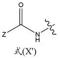
wherein Z is a blocking group optionally having a reactive end group (e.g., a polymerizable end group, such as an epoxy, alkene, alkyne, or thiol end group, e.g., an ethylenically unsaturated end group, such as a vinyl ether). In a particular example, each a 'is an independently selected substituent of formula (XI'):

the other components and steps of these methods are performed in a similar manner as described in section ix.a. above.
In one non-limiting example, a blocked diisocyanate is prepared as shown in the following scheme. Such a blocked diisocyanate can be used in a process as shown in fig. 26B.

Without wishing to be bound by any particular potential mechanism, in some embodiments, during thermal curing, the blocking agent is cleaved and the chain extender reacts to form a thermoplastic or thermoset polyurethane, polyurea, or copolymer thereof (e.g., poly (urethane-urea)):

In an alternative mechanism, in forming a thermoplastic or thermoset polyurethane, polyurea, or copolymer thereof (e.g., poly (urethane-urea)), the chain extender reacts with the blocked diisocyanate or branched isocyanate, removing the blocking agent.
In general, the three-dimensional product of the above-described process comprises (i) a linear thermoplastic polyurethane, polyurea, or copolymer thereof (e.g., poly (urethane-urea)), (ii) a crosslinked thermoset polyurethane, polyurea, or copolymer thereof (e.g., poly (urethane-urea)), or (iii) a combination thereof (optionally blended with deblocked blocking groups copolymerized with one or more reactive diluents, e.g., in the form of an interpenetrating polymer network, a semi-interpenetrating polymer network, or a sequential interpenetrating polymer network). In some exemplary embodiments, the three-dimensional product may further include unreacted photoinitiator remaining in the three-dimensionally shaped object. For example, in some embodiments, from 0.1 or 0.2 wt% to 1, 2, or 4 wt% of the photoinitiator may remain in the three-dimensionally shaped object or the photoinitiator may be present in lower amounts or only trace amounts. In some exemplary embodiments, the three-dimensional product may also include reacted photoinitiator fragments. For example, in some embodiments, the reacted photoinitiator fragment may be the residue of a first cure that forms an intermediate product. For example, from 0.1 or 0.2 wt% to 1, 2 or 4 wt% of reacted photoinitiator fragments may remain in the three-dimensionally shaped object or reacted photoinitiator fragments may be present in lower amounts or only trace amounts. In exemplary embodiments, the three-dimensional product may comprise, consist of, or consist essentially of all or any combination of linear thermoplastic polyurethane, crosslinked thermoset polyurethane, unreacted photoinitiator, and reacted photoinitiator material.
Although this embodiment has been described above primarily with respect to reactive blocking groups, it is to be appreciated that non-reactive blocking groups may also be used.
Furthermore, although less preferred, it is to be appreciated that the process as described above may also be carried out without a sealant, while still providing the dual cure process and product of the present invention.
Further, while this embodiment is described primarily with diol and diamine chain extenders, it is recognized that chain extenders having more than two reactive groups (polyols and polyamine chain extenders such as triols and triamine chain extenders) can be used to form three-dimensional objects comprising crosslinked thermoset polyurethanes, polyureas, or copolymers thereof (e.g., poly (urethane-urea)).
These materials may be used in bottom-up additive manufacturing techniques, such as the continuous liquid interface printing techniques described herein, or other additive manufacturing techniques as described above and below.
C. A dual-hardening polymerizable liquid of blocked chain extenders and thermally cleavable deblocking groups is used.
Another embodiment provides a method of forming a three-dimensional object comprising a polyurethane, polyurea, or copolymer thereof (e.g., a poly (urethane-urea)), the method comprising:
(a) providing a carrier and an optically transparent member having a build surface, the carrier and the build surface defining a build area therebetween;
(b) Filling the build region with a polymerizable liquid comprising a mixture of (i) a polyol and/or polyamine, (ii) a blocked or reactively blocked diisocyanate or branched isocyanate chain extender, (iii) optionally one or more additional chain extenders, (iv) a photoinitiator, and (v) optionally but in some embodiments preferred reactive diluent (vi) optionally but in some embodiments preferred pigment or dye, (vii) optionally but in some embodiments preferred filler (e.g. silica);
(c) irradiating the build region with light through the optically transparent member to form a closed chain (blocked chain) diisocyanate or branched isocyanate chain extender solid scaffold from the blocked or reactively blocked diisocyanate or branched isocyanate chain extender and optionally the reactive diluent and advancing the support away from the build surface to form a three-dimensional intermediate having the same shape as or to be imparted to a three-dimensional object, the intermediate containing a polyol and/or a polyamine and optionally one or more additional chain extenders; and then
(d) Heating or microwave irradiating the three-dimensional intermediate sufficient to form a polyurethane, polyurea, or a combination thereof from the three-dimensional intermediate A three-dimensional product of a copolymer (e.g., a poly (urethane-urea)) such as sufficient heat or microwave irradiation to deblock a blocked diisocyanate or branched isocyanate chain extender to form an unblocked diisocyanate chain extender, which in turn is polymerized with a polyol and/or a polyamine and optionally one or more additional chain extenders.
In some embodiments, the blocked or reactive blocked diisocyanate or branched isocyanate chain extender comprises a compound of the formula A ' -X ' -A ' or X ' (-A ')nWherein n is at least 2.1, 2.3, 2.5 or 3 (on average), wherein X "is a hydrocarbyl group, and each a" is an independently selected substituent of formula (X "):

wherein R is a hydrocarbyl group, R' is O or NH, and Z is a blocking group, optionally having a reactive end group (e.g., a polymerizable end group, such as an epoxy, alkene, alkyne, or thiol end group, e.g., an ethylenically unsaturated end group, such as a vinyl ether). In a particular example, each a "is an independently selected substituent of formula (XI"):

wherein R and R' are as given above.
The other ingredients and steps used in carrying out these methods may be the same as described in section ix.a above.
One example of the preparation of the blocked glycol chain extender is shown in the following scheme.

An example of the preparation of a blocked diamine chain extender is shown in the following scheme:

an example of the method of the present invention performed with the above-described materials is given in fig. 26C.
Without wishing to be bound by any potential mechanism of the present invention, in some embodiments, during thermal curing,(a)the blocked isocyanate terminated chain extender reacts directly with the soft segment and/or chain extender amine or alcohol groups to displace the blocking agent; or(b)The blocked isocyanate terminated chain extender cleaves and reforms the diisocyanate terminated chain extender and reacts with the soft segment and, if necessary, additional chain extender to produce a thermoplastic or thermoset polyurethane, polyurea, or copolymer thereof (e.g., poly (urethane-urea)), such as the following reactions:

another mechanism similar to that described in section ix.b. above may also be implemented or used.
In general, the three-dimensional product of the above method comprises(i) Linear thermoplastic polyurethanes, polyureas, or copolymers thereof (e.g., poly (urethane-urea)),(ii)a crosslinked thermoset polyurethane, polyurea, or copolymer thereof (e.g., poly (urethane-urea)), or(iii) Combinations thereof (optionally blended with a deblocked blocking group copolymerized with one or more reactive diluents, e.g., in the form of an interpenetrating polymer network, a semi-interpenetrating polymer network, or a sequential interpenetrating polymer network). In some exemplary embodiments, the three-dimensional product may further comprise unreacted photoinitiator remaining in the three-dimensionally shaped object. For example, in some embodiments, from 0.1 or 0.2 wt% to 1, 2, or 4 wt% of the photoinitiator may remain in the three-dimensionally shaped object or the photoinitiator may be present in lower amounts or only trace amounts. In some exemplary embodiments, the three-dimensional product may further comprise reacted photoinitiator fragments. For example, in some embodiments, the reacted photoinitiator fragment may be the residue of a first cure that forms an intermediate product. For example, 0.1 or 0.2 wt% to 1, 2 or 4 wt% of the reacted light Initiator fragments may remain in the three-dimensionally shaped object or reacted photoinitiator fragments may be present in lower amounts or only trace amounts. In exemplary embodiments, the three-dimensional product may comprise, consist of, or consist essentially of all or any combination of linear thermoplastic polyurethane, crosslinked thermoset polyurethane, unreacted photoinitiator, and reacted photoinitiator material.
Although this embodiment has been described above primarily with respect to reactive blocking groups (i.e., blocking groups containing polymerizable moieties), it is to be appreciated that non-reactive blocking groups may also be used.
Furthermore, although less preferred, it is to be appreciated that the process as described above may also be carried out without a sealant, while still providing the dual cure process and product of the present invention.
Further, while this embodiment is described primarily with diol and diamine chain extenders, it is recognized that chain extenders having more than two reactive groups (polyols and polyamine chain extenders such as triols and triamine chain extenders) can be used to form three-dimensional objects comprising crosslinked thermoset polyurethanes, polyureas, or copolymers thereof (e.g., poly (urethane-urea)).
These materials may be used in bottom-up additive manufacturing techniques, such as the continuous liquid interface printing techniques described herein, or other additive manufacturing techniques as described above and below.
Those skilled in the art will recognize that, for example, Ying and Cheng, Hydrolyzable polymers Bearing ordered Urea Bonds, JACS 136, 169974 (2014) may be used to implement the methods described herein.
An article comprised of an Interpenetrating Polymer Network (IPN) formed from a dual cure polymerizable liquid.
In some embodiments, polymerizable liquids comprising a dual cure system as described above may be used to form three-dimensional articles that in turn comprise interpenetrating polymer networks. This area has been noted by Sperling of Lehigh University and K.C. Frisch et al of University of Detroit.
In a non-limiting example, the polymerizable liquid and method steps are selected such that the three-dimensional object comprises the following:
a sol-gel composition.This can be done with an amine (ammonia) permeable window or a semi-permeable member. In the system discussed herein, Tetraethylorthosilicate (TEOS), epoxy resin (diglycidyl ether of bisphenol A), and 4-aminopropyltriethoxysilane may be added to the free radical crosslinking agent, which in this process polymerizes and contains the indicated reactants, which are then reacted in another step or stage. The reaction requires the presence of water and an acid. A photoacid generator (PAG) may optionally be added to the above mixture to facilitate the reaction of the silica-based network. It is noted that if only TEOS is included, a silica (glass) network is finally obtained. The temperature can then be increased to remove the organic phase and leave behind a silica structure that is difficult to prepare by more conventional methods. Many variants (different polymer structures) can be prepared by this method in addition to epoxy resins, including polyurethanes, functionalized polyols, silicone rubbers, and the like.
Hydrophobic-hydrophilic IPNs.Previous IPN studies contain many examples of hydrophobic-hydrophilic networks for improving the hemocompatibility and histocompatibility of biomedical components. Poly (hydroxyethyl (meth) acrylate) is a typical example of the hydrophilic component. Another option is to add poly (ethylene oxide) polyols or polyamines with isocyanates to make polyurethanes, polyureas or copolymers thereof (e.g. poly (urethane-urea)) incorporated into reactive systems.
Phenolic resins (resole resins).The precursor of the phenolic resin is a resole (formaldehyde-terminated liquid oligomer) or a novolac (phenol-terminated solid oligomer crosslinkable with hexamethyltetramine). For the present process, phenolic resole resins may be considered. Its viscosity may be high but it can be diluted with alcohol (methanol or ethanol). The combination of the phenolic resole resin and the crosslinkable monomer can then provide a product formed from the IPN. The reaction of the resole with the phenolic resin can be carried out at temperatures above 100 ℃ in a short time frame. One variation of this chemical is to carbonize the resulting structure into carbon or graphite. Carbon or graphite foams are typically made from phenolic foam and are used for thermal insulation at high temperatures。
And (3) a polyimide. Polyimides based on dianhydrides and diamines may be suitable for use in the present process. In this case, the polyimide monomer incorporated in the reactive crosslinkable monomer is reacted to produce the IPN structure. Most dianhydrides used in polyimides can be crystalline at room temperature but a suitable amount of volatile solvent can provide the liquid phase. The network may be reacted after polymerization at mild temperatures (e.g., about 100 ℃) to allow formation of a polyimide.
A conductive polymer.Aniline and ammonium persulfate were incorporated into the polymerizable liquid for making the conductive parts. After the reactive system is polymerized and post-treated with an acid (e.g., HCl vapor), polymerization to polyaniline may then begin.
Natural product based IPNs.Many IPNs based on natural products based on triglyceride oils, such as castor oil, are known. These may be incorporated into the polymerizable liquid together with the isocyanate. After the part is completed, the triglyceride may then be reacted with the diisocyanate to form a crosslinked polyurethane. Of course glycerol may also be used.
Sequential IPNIn this case, the molded crosslinked network is swollen with monomers and a free radical catalyst (peroxide) and optionally a crosslinking agent, followed by polymerization. The crosslinked triacrylate system should absorb (imbide) large amounts of styrene, acrylate and/or methacrylate monomers to enable the preparation of a sequential IPN.
Polymerization of polyolefinsA polyolefin catalyst (e.g., a metallocene) can be added to the crosslinkable reactive system. The part may then contain moderate to significant amounts of polyolefin when exposed to pressurized ethylene (or propylene) or combinations (to make EPR rubbers) and temperatures of 100 ℃. Ethylene, propylene and alpha olefin monomers should diffuse readily into the section to react with the catalyst at this temperature and as polymerization proceeds, more olefin diffuses into the catalyst site. A large number of components can be postpolymerized simultaneously.
Xi. manufacture of product.
A. Example three-dimensional (3D) objects.
The three-dimensional product produced by the method and process of the present invention may be a finished, finished or base product, or may be an intermediate product for which further manufacturing steps are contemplated, such as surface treatment, laser cutting, electrical discharge machining, and the like. Intermediate products include products that can be further additively manufactured in the same or different devices. For example, faults (faults) or split lines can be deliberately introduced into an ongoing "build" by breaking and then reconstructing the gradient of the polymerization zone to end a region of the final product, or simply because a particular region of the final product or "build" is less brittle than the others.
Many different products can be manufactured by the method and apparatus of the present invention, including large models or prototypes, small customized products, miniature or miniature products or devices, and the like. Examples include, but are not limited to, medical devices and implantable medical devices, such as stents, drug delivery reservoirs, functional structures, microneedle arrays, fibers and rods such as waveguides, micromechanical devices, microfluidic devices, and the like.
Thus, in some embodiments, the product can have a height of 0.1 or 1 millimeter to 10 or 100 millimeters or more, and/or a maximum width of 0.1 or 1 millimeter to 10 or 100 millimeters or more. In other embodiments, the product may have a height of 10 or 100 nanometers to 10 or 100 micrometers, and/or a maximum width of 10 or 100 nanometers to 10 or 100 micrometers or more. These are only examples: the maximum size and width depend on the architecture of the particular device and the resolution of the light source and may be adjusted according to the particular goal of the embodiment or article of manufacture.
In some embodiments, the product has an aspect ratio of at least 2:1, 10:1, 50:1, or 100:1 or greater, or an aspect ratio of 1:1, 10:1, 50:1, or 100:1 or greater.
In some embodiments, the product has at least one or more apertures or channels formed therein, as discussed further below.
The methods described herein can produce products having a variety of different properties. Thus in some embodiments the product is rigid; in other embodiments the product is flexible or resilient. In some embodiments, the product is a solid; in other embodiments, the product is a gel, such as a hydrogel. In some embodiments, the products have shape memory (i.e., substantially recover a previous shape after deformation, so long as they do not deform to the point of structural failure). In some embodiments, the product is unitary (i.e., formed from a single polymerizable liquid); in some embodiments, the product is a composite (i.e., formed from two or more different polymerizable liquids). The particular properties are determined by factors such as the choice of polymerizable liquid or liquids used.
In some embodiments, the resulting product or article has at least one suspension member (or "overhang"), such as a bridging element between two supports, or a cantilevered (cantilevered) element protruding from a substantially vertical support body. Due to the unidirectional, continuous nature of some embodiments of the present method, the problem of forming faults or split lines between layers is significantly reduced when each layer is polymerized to substantial completion and there is a sufficient time interval before the next pattern is exposed. Thus, in some embodiments, the method is particularly advantageous in reducing or eliminating the number of support structures for such overhangs that are manufactured at the same time as the article.
B. Exemplary structures and geometries of 3D objects.
In exemplary embodiments, a three-dimensional (3D) object may be formed, imparting thousands or millions of shape changes to the three-dimensional object while forming. In an exemplary embodiment, the pattern generator generates different light patterns to activate the photoinitiator in the region of the polymerization gradient to provide different shapes when the (extracted) object is extracted via the polymerization gradient. In an exemplary embodiment, the pattern generator may have a high resolution, with millions of pixel elements that may vary to change the imparted shape. For example, the pattern generator may be a DLP with more than 1,000 or 2,000 or 3,000 or more rows and/or more than 1,000 or 2,000 or 3,000 or more columns of micro mirrors (or pixels in a liquid crystal panel), which may be used to change shape. Thus, the object may be given very fine variations or gradations along its length. In exemplary embodiments, this enables complex three-dimensional objects to be formed at high speeds with substantially continuous surfaces that are free of splits or seams. In some examples, the three-dimensional object in formation can be imparted with greater than hundreds, thousands, tens of thousands, hundreds of thousands, or millions of shape changes, without splits or seams, across a length of the object in formation greater than 1 millimeter, 1 centimeter, 10 centimeters, or more, or across the entire length of the object that has been formed. In exemplary embodiments, the object may be continuously formed by a gradient of polymerization at a rate of greater than 1, 10, 100, 1000, 10000 microns/second or more.
In an exemplary embodiment, this can form complex three-dimensional (3D) objects. In some exemplary embodiments, the 3D shaped object has a complex non-injection moldable shape. This shape cannot be easily formed using injection molding or casting. For example, the shape may not be formed by discrete mold elements that cooperate to form a cavity into which a filler material is injected and cured, such as a conventional concavo-convex mold (two-part mold). For example, in some embodiments, the 3D shaped object may comprise closed or partially open cavities, repeating unit cells (repeating unit cells), or open or closed cell foam structures that are not suitable for injection molding and may comprise hundreds, thousands, or millions of these structures or an interconnected network of these structures. However, in exemplary embodiments, these shapes can be 3D formed with a wide range of properties (including a wide range of elastomeric properties, tensile strength, and elongation to break) using the methods described herein by forming these structures using dual cure materials and/or interpenetrating polymer networks. In exemplary embodiments, 3D objects may be formed without split lines, seams, gates, gate marks, or pin marks that may be present using injection molding or other conventional techniques. In some embodiments, the 3D shaped object may have a continuous surface texture (whether smooth, patterned, or rough) that is free of molding or other printed marks (artifacts) such as split lines, seams, gates, gate marks, or pin marks across a length of greater than 1 millimeter, 1 centimeter, 10 centimeters, or more, or across the entire length of the shaped object. In exemplary embodiments, complex 3D objects may be formed that do not have visible or easily detectable discrete layers from the printing process across a length of greater than 1 millimeter, 1 centimeter, 10 centimeters, or more in the finished 3D object or across the entire length of the formed object. For example, the changing shape imparted by the pattern generator during printing may not be visible or perceived as a distinct layer in the finished 3D object because the printing occurs via a gradient of polymerization zones (thereby extracting the 3D object when it is exposed to the changing pattern projected by the pattern generator). Although the 3D object obtained from such a method may be referred to as a 3D printed object, the 3D object may be formed by continuous liquid interface printing without the discrete layers or break lines associated with some 3D printing methods.
In some embodiments, the 3D shaped object may include one or more repeating structural elements to form a 3D object, including, for example, as (or substantially corresponding to) closed cavities, partially closed cavities, repeating unit cells or networks of unit cells, foam cells (foam cells), Kelvin foam cells or other open or closed cell foam structures, cross-over structures, catenary structures, pendants, microneedles, fibers, paddles, protrusions, needles, dimples, rings, tunnels, tubes, shells, plates, beams (including I-beams, U-beams, W-beams, and cylindrical beams), struts, tie-rods, channels (open, closed, or partially closed), waveguides, triangular structures, tetrahedral or other pyramidal shapes, cubes, octahedrons, octagonal prisms, dodecahedrons, triacontrons, or other polyhedral shapes or modules (including Kelvin tratrabechedrons (tekaidecahedra)), Prismatic or other polyhedral shape), pentagonal, hexagonal, octagonal, and other polygonal structures, or structures of prisms, polygonal meshes, or other three-dimensional structures. In some embodiments, the 3D shaped object may include any combination of these structures or an interconnected network of these structures. In an exemplary embodiment, all or a portion of the structure of the 3D shaped object may correspond to (or substantially correspond to) one or more bravais lattices or unit cell structures, including cubic (including simple, body-centered, or face-centered), tetragonal (including simple or body-centered), monoclinic (including simple or bottom-centered), orthorhombic (including simple, body-centered, face-centered, or bottom-centered), rhombohedral, hexagonal, and triclinic structures. In exemplary embodiments, the 3D shaped object may include a shape or surface corresponding to (or substantially corresponding to) a catenary curve, a helicoid, gyroid (or lidinoid), other tri-periodic surface minima (TPMS), or other geometry from the related family (or Bonnet family), or a Schwarz P ("pristine") or Schwarz D ("diamond"), Schwarz H ("hexagonal"), or Schwarz CLP ("parallel-crossed layers") surface, a diamond pattern or diamond pattern, a lattice, or other pattern or structure.
In an exemplary embodiment, the pattern generator may be programmed to change rapidly during printing to impart different shapes to the polymerization gradient with high resolution. Thus, any of the structural elements described above may be formed in a wide range of sizes and properties and may be repeated or combined with other structural elements to form a 3D object. In exemplary embodiments, the 3D shaped object may comprise a single three-dimensional structure or may comprise more than 1, 10, 100, 1000, 10000, 100000, 1000000, or more of these structural elements. The structural elements may be repeating structural elements of similar shape or a combination of different structural elements and may have any of those described above or other regular or irregular shapes. In exemplary embodiments, each of the structural elements may have a dimension across the structure of at least 10 nanometers, 100 nanometers, 10 micrometers, 100 micrometers, 1 millimeter, 1 centimeter, 10 centimeters, 50 centimeters or more or may have a dimension across the structure of less than 50 centimeters, 10 centimeters, 1 centimeter, 1 millimeter, 100 micrometers, 10 micrometers, 100 nanometers, or 10 nanometers or less. In example embodiments, the height, width, or other dimension across the structure may be from about 10 nanometers to about 50 centimeters or more, or any range contained therein. As used herein, "any range contained therein" means any range within the specified range. For example, the following are included in the range of about 10 nanometers to about 50 centimeters and are included herein: 10 nanometers to 1 micron; 1 micron to 1 millimeter; 1 mm to 1 cm; and 1 centimeter to 50 centimeters or any other range or set of ranges within the specified range. In exemplary embodiments, the structural elements can form a volume of the 3D object in a range of about 10 square nanometers to about 50 square centimeters or more, or any range contained therein. In example embodiments, the structural elements may form cavities or hollow regions or gaps between surfaces of the structural elements, have dimensions across the cavities or hollow regions or gaps in a range of about 10 nanometers to about 50 centimeters or more or any range contained therein, or may define a volume in a range of about 10 square nanometers to about 50 square centimeters or more or any range contained therein in the area of the 3D shaped object.
The structural elements may be of substantially the same size or the size may vary within the volume of the 3D shaped object. The dimensions may increase or decrease (gradually or stepwise) from one side of the 3D shaped object to the other or elements of different shapes may be intermixed in a regular or irregular pattern (e.g., 3D resilient foam with open and/or closed cells of different sizes intermixed throughout the foam).
In some embodiments, the 3D shaped object may have an irregular shape with overhangs, bridging elements, or asymmetries or may have an offset center of gravity in the shaping direction. For example, the 3D shaped object may be asymmetric. In exemplary embodiments, the 3D shaped object may not have rotational symmetry about any axis or may have rotational symmetry about only a single axis. In exemplary embodiments, the 3D shaped object may have no reflection symmetry about any plane passing through the 3D shaped object or may have reflection symmetry about only a single plane. In an exemplary embodiment, the 3D object may have an offset center of gravity. For example, the center of gravity of the 3D shaped object may not be at the center of the location of the object. In some instances, the center of gravity may not be located along any central axis of the object. For example, the 3D shaped object may be a sole or insole that substantially follows the contours of the foot. The sole or insole may be inclined to the right or left and have different widths for the heel and toes. Thus, the 3D shaped object has no edge-to-edge or front-to-back reflective symmetry in this example. However, if it is a uniformly flat sole or insole, it may have a bottom-to-top reflection symmetry. In other examples, the sole or sockliner may be flat on one side and contoured on the other side to receive the arch of the foot, and thus not have bottom-to-top reflective symmetry. Other 3D shaped objects for wearable, prosthetic, or anatomical profiles or devices may have similar asymmetric and/or offset centers of gravity. For example, a 3D shaped object for a dental cast or implant may substantially conform to the shape of a tooth and may not have reflective symmetry about any plane. In another example, a 3D shaped component for a wearable device may substantially conform to the shape of a body (body party) and have a corresponding asymmetry, such as athletic equipment, such as a right or left shaped leg guard or a foam pad or insert used between a hard leg guard or helmet or other wearable component and the human body. These are merely examples, and many 3D shaped objects may be asymmetric and/or have an offset center of gravity. In exemplary embodiments, if there is a significant asymmetry or protruding element (e.g., arm, bridging element, cantilever, brush fiber, etc.) and the desired structural element is elastic, there is a possibility of deformation during 3D printing or subsequent curing. For example, if a large amount of non-UV curable elastomeric resin material is included, gravity may cause deformation prior to final curing. Although the scaffold formed from the UV curable material (by initial curing in a dual cure process) helps to lock in this shape during 3D printing, some elastomeric compositions having highly asymmetric or protruding shapes may be easily deformed. In some exemplary embodiments, the UV curable material in the composition may be adjusted to form a more rigid scaffold to avoid deformation. In other exemplary embodiments, objects having asymmetric shapes and/or offset centers of gravity may be formed in pairs (or in other combinations) with connectors that are later removed, particularly if the 3D shaped object or protruding element is relatively long. In one example, the elastomeric 3D object may be shaped along a length and have an asymmetry, center of gravity offset, and/or protruding elements transverse to the length that is greater than 10%, 20%, 30%, 40%, 50%, or more of the length. For example, the 3D shaped object may have a length of about 1 centimeter to 50 centimeters or more, or any range contained therein, and may have a lateral or laterally asymmetric or protruding element of about 1 centimeter to 50 centimeters or more, or any range contained therein. In an exemplary embodiment, two or more of these objects may be shaped together to provide support for the transverse or protruding elements until the elastomeric material cures and separates the objects. For example, two soles may be formed in pairs (e.g., when formed in their lengthwise direction) (e.g., a swivel and inverted sole formed together with a small removable connection between them) so that the soles provide support for each other while being formed. In other exemplary embodiments, other support structures may be formed and removed after the elastomeric material is cured.
C. Example materials and compositions of 3D objects
In exemplary embodiments, the 3D shaped object may have any of the above shapes or structures and may comprise: (i) linear thermoplastic polyurethanes, polyureas, or copolymers thereof (e.g., poly (urethane-urea)), (ii) crosslinked thermoset polyurethanes, polyureas, or copolymers thereof (e.g., poly (urethane-urea)), and/or (iii) combinations thereof (optionally blended with a deblocked blocking group copolymerized with one or more reactive diluents, e.g., in the form of an interpenetrating polymer network, a semi-interpenetrating polymer network, or a sequential interpenetrating polymer network) and/or (iv) photoinitiators (including unreacted photoinitiators and/or reacted photoinitiator segments) and/or consisting essentially of or consisting of them.
In some exemplary embodiments, silicone rubber 3D objects may be formed.
1. Polysiloxane polyurethane, polyurea, or poly (urethane-urea).In any of the above polyurethane examples, polysiloxane or poly (dimethylsiloxane) (PDMS) may be used as the soft segment in the formation of these materials. For example, a (meth) acrylate functional ABPU may be formed by first reacting an oligomeric PDMS diol or diamine with 2 equivalents of isocyanate to form a PDMS urethane (urethane) prepolymer. This material may be further reacted with TBAEMA or other reactive blocking agents described herein to form a reaction A blocked PDMS prepolymer that can be blended with chain extenders and reactive diluents as described in the examples above.
2. Polysiloxane interpenetrating polymer networksIn some embodiments, the material may comprise, consist essentially of or consist of a UV-curable PDMS oligomer blended with a two-part (two-part) thermally curable PDMS oligomer system.
In exemplary embodiments, the 3D shaped object may have any of the shapes or structures described above and may comprise, consist of, or consist essentially of:
(i) thermoset polysiloxane or PDMS networks cured by platinum catalyzed hydrosilation, tin catalyzed condensation chemistry, or peroxide initiated chemistry.
(ii) A UV-curable reactive diluent miscible with the silicone thermoset oligomer prior to curing. Example (c): acrylate functional PDMS oligomers.
(iii) Combinations thereof (optionally blended with one or more reactive diluents, e.g., in the form of an interpenetrating polymer network, a semi-interpenetrating polymer network, or a sequential interpenetrating polymer network), and/or
(iv) A photoinitiator comprising unreacted photoinitiator and/or reacted photoinitiator fragments.
In an exemplary embodiment, THINKY is used TMThe mixer dissolves phenyl bis (2,4, 6-trimethylbenzoyl) phosphine oxide (PPO) in isobornyl acrylate (IBA). Methacryloxypropyl-terminated polydimethylsiloxane (DMS-R31; Gelest Inc.) was added to this solution, followed by Sylgard Part A and Part B (Corning PDMS precursor), which were then further mixed with a THINKY ™ mixer to produce a homogeneous solution. The solution was loaded into the apparatus as described above and a three-dimensional intermediate was produced by uv curing as described above. The three-dimensional intermediate is then heat cured at 100 ℃ for 12 hours to produce the final silicone rubber product.
3. An interpenetrating network of epoxy.In some exemplary embodiments, epoxy 3D objects may be formed. In exemplary embodiments, the 3D shaped object may have any of the shapes described aboveOr structure and may include:
(i) a thermosetting epoxy network cured by reaction of a diepoxide with a diamine. Optionally, co-reactants may also be included, such as: co-reactants including polyfunctional amines, acids (and anhydrides), phenols, alcohols, and thiols;
(ii) a UV-curable reactive diluent miscible with the epoxy thermoset precursor prior to curing;
(iii) combinations thereof (optionally blended with one or more reactive diluents, e.g., in the form of an interpenetrating polymer network, a semi-interpenetrating polymer network, or a sequential interpenetrating polymer network), and/or
(iv) A photoinitiator comprising or consisting essentially of unreacted photoinitiator and/or reacted photoinitiator fragments.
In one exemplary embodiment: 10.018 grams of Epoxacat 690 resin part A and 3.040 grams of part B were mixed on a THINKY ™ mixer. 3.484 grams were then mixed with 3.013 grams of RKP5-78-1(Sartomer CN 9782/N-vinylpyrrolidone/diethylene glycol diacrylate 65/22/13 blend) to produce a clear blend, which was cured under a Dymax ultraviolet lamp to produce an elastic 3D object.
In a second exemplary embodiment, RKP11-10-1 containing 3.517 grams of the above epoxy resin and 3.508 grams of 65/33/2/0.25 blend of RKP5-90-3 and Sartomer CN 2920/N-vinylcaprolactam/N-vinylpyrrolidone/PPO initiator was similarly cured to form a flexible 3D object.
In some exemplary embodiments, the 3D shaped object may comprise a sol-gel composition, a hydrophobic or hydrophilic composition, a phenolic resole resin, a cyanate ester, a polyimide, a conductive polymer, a natural product based IPN, a sequential IPN, and a polyolefin as described above.
In exemplary embodiments, the 3D shaped object may have any of the shapes or structures described above and may comprise, consist essentially of, or consist of a plurality of different materials having different tensile strengths or other different properties in different regions of the 3D shaped object. In exemplary embodiments, these different materials may be selected from any of the materials described above. In some exemplary embodiments, the method of making the product may be paused or interrupted one or more times to change the polymerizable liquid. In exemplary embodiments, the 3D shaped object may comprise a plurality of materials (which may be, for example, thermoplastic or thermoset polyurethane, polyurea or copolymers thereof, or silicone rubber or epoxy, or combinations thereof) having different tensile strengths as described further below. Although a fault line or a surface may form in the intermediate due to the interruption, if the subsequent polymerizable liquid is reactive with the first curable material in its second curable material, the two different segments of the intermediate will cross-react and covalently couple to each other (e.g., by heating or microwave irradiation) during the second curing process. Thus, for example, any of the materials described herein can be sequentially altered to form a product having a plurality of different segments that differ in tensile properties, while still being a unitary product having the different segments covalently coupled to one another.
In exemplary embodiments, the polyurethane, polyurea, or copolymers thereof (e.g., poly (urethane-urea)), or polysiloxane rubber or epoxy, or combinations of the above, may comprise a majority by weight of the 3D shaped object, and may comprise greater than 50%, 60%, 70%, 80%, or 90% by weight of the 3D shaped object. In exemplary embodiments, the polyurethane, polyurea, or copolymer thereof (e.g., poly (urethane-urea)), or polysiloxane rubber or epoxy, or combinations thereof, may comprise, consist essentially of, or consist of an interpenetrating network, a semi-interpenetrating polymer network, or a sequential interpenetrating polymer network.
(i) Examples of thermoplastic or thermoset polyurethanes, polyureas, or copolymers thereof (e.g., poly (urethane-urea)).In exemplary embodiments, the polyurethane, polyurea, or copolymer thereof (e.g., poly (urethane-urea)) may constitute a majority by weight of the 3D shaped object, and may constitute greater than 50%, 60%, 70%, 80%, or 90% by weight of the 3D shaped object.
In exemplary embodiments, the polyurethane, polyurea, or copolymer thereof (e.g., poly (urethane-urea)), can comprise, consist essentially of, or consist of a linear thermoplastic or thermoset polyurethane, polyurea, or copolymer thereof (e.g., poly (urethane-urea)). In exemplary embodiments, the linear thermoplastic or crosslinked thermoset polyurethane, polyurea, or copolymer thereof (e.g., poly (urethane-urea)) may comprise a majority by weight of the 3D shaped object, and may comprise greater than 50%, 60%, 70%, 80%, or 90% by weight of the 3D shaped object.
In exemplary embodiments, the polyurethane, polyurea, or copolymer thereof (e.g., poly (urethane-urea)) may comprise, consist essentially of, or consist of a polymer blend of (i) a linear ethylenically unsaturated blocking monomer copolymerized with a reactive diluent and (ii) a linear thermoplastic or crosslinked thermoset polyurethane, polyurea, or copolymer thereof (e.g., poly (urethane-urea)). In exemplary embodiments, the polymer blend may constitute a majority by weight of the 3D shaped object and may constitute greater than 50%, 60%, 70%, 80%, or 90% by weight of the 3D shaped object. In exemplary embodiments, the linear thermoplastic or crosslinked polyurethane, polyurea, or copolymer thereof (e.g., poly (urethane-urea)) may comprise, consist essentially of, or consist of a linear poly (meth) acrylate.
In exemplary embodiments, the polyurethane, polyurea, or copolymer thereof (e.g., poly (urethane-urea)) may comprise or consist essentially of an interpenetrating network, semi-interpenetrating polymer network, or sequential interpenetrating polymer network of ethylenically unsaturated monomer and crosslinked or linear polyurethane. In exemplary embodiments, the network of ethylenically unsaturated monomers and crosslinked polyurethane may comprise a majority by weight of the 3D shaped object, and may comprise greater than 50%, 60%, 70%, 80%, or 90% by weight of the 3D shaped object. In exemplary embodiments, the linear thermoplastic or crosslinked thermoset polyurethane, polyurea, or copolymer thereof (e.g., poly (urethane-urea)) may comprise, consist essentially of, or consist of a crosslinked poly (meth) acrylate.
In exemplary embodiments, the polyurethane, polyurea, or copolymer thereof (e.g., poly (urethane-urea)) may comprise, consist essentially of, or consist of an interpenetrating network, a semi-interpenetrating polymeric network, or a sequential interpenetrating polymeric network of ethylenically unsaturated monomers and linear thermoplastic or crosslinked thermoset polyurethane. In exemplary embodiments, the network of ethylenically unsaturated monomers and linear thermoplastic or crosslinked thermoset polyurethane may comprise a majority by weight of the 3D shaped object, and may comprise greater than 50%, 60%, 70%, 80%, or 90% by weight of the 3D shaped object. In exemplary embodiments, the linear thermoplastic or crosslinked thermoset polyurethane, polyurea, or copolymer thereof (e.g., poly (urethane-urea)) may comprise, consist essentially of, or consist of a linear poly (meth) acrylate.
In some exemplary embodiments, the 3D shaped object may comprise a sol-gel composition, a hydrophobic or hydrophilic composition, a phenolic resole resin, a cyanate ester, a polyimide, a conductive polymer, a natural product based IPN, a sequential IPN, and a polyolefin as described above.
(ii) Examples photoinitiators and photoinitiator fragments.In an exemplary embodiment, the 3D shaped object may include unreacted photoinitiator remaining in the 3D shaped object. For example, in some embodiments, from 0.1 or 0.2 wt% to 1, 2, or 4 wt% of the photoinitiator may remain in the three-dimensionally shaped object or the photoinitiator may be present in lower amounts or only trace amounts. In some exemplary embodiments, the three-dimensional product may further comprise reacted photoinitiator fragments. For example, in some embodiments, the reacted photoinitiator fragment may be the residue of a first cure that forms an intermediate product. For example, from 0.1 or 0.2 wt% to 1, 2 or 4 wt% of reacted photoinitiator fragments may remain in the three-dimensionally shaped object or reacted photoinitiator fragments may be present in lower amounts or only trace amounts.
In exemplary embodiments, because the system is composed in part of monomers and oligomers that can be polymerized by exposure to ultraviolet light, the final product will contain residual photoinitiator molecules and photoinitiator fragments.
In some embodiments, the photopolymerization will undergo the transformations outlined below. In the first step (initiation), uv light cleaves the initiator into reactive free radical fragments. These reactive free substrate fragments continue to react with the monomer groups "M". During the growing step, the reactive monomer reacts with additional monomers attached to the growing polymer chain. Finally, termination may occur by recombination or by disproportionation.

In exemplary embodiments, the 3D shaped object produced by the methods outlined herein may contain the following chemical products after the object is made:
(1) latent (Latent) unreacted photoinitiator-the photoinitiator is rarely 100% consumed during photopolymerization, so the product typically contains unreacted photoinitiator embedded throughout the solid object:
(2) a photoinitiator by-product covalently attached to the polymer network.
In exemplary embodiments, the photoinitiator may include the following:
(a) based on benzoyl-chromophores These systems take the form of

Where "R" is a variety of other atoms, including H, O, C, N, S. These initiators cleave to form:

wherein ● represents a radical. Any of these components can continue to initiate polymerization and thus covalently bond to the polymer network.

An example of such an initiator is shown below
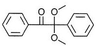
(b) Morpholino and aminoketonesThese systems take the form of:

where "R" is a variety of other atoms, including H, O, C, N, S. These initiators cleave to form

Wherein ● represents a radical. Any of these components can continue to initiate polymerization and thus covalently bond to the polymer network.

An example of such an initiator is shown below

(c) Benzoylphosphine oxidesThese systems take the form of

Where "R" is a variety of other atoms, including H, O, C, N, S. These initiators cleave to form

Wherein ● represents a radical. Any of these components can continue to initiate polymerization and thus covalently bond to the polymer network.

An example of such an initiator is shown below

(d) Amines as pesticidesA number of photoinitiators can be used in combination with the amine. The photoinitiators in the excited state are used here to abstract hydrogen atoms from the amines, whereby reactive radicals are generated. Such free radicals may continue to initiate polymerization and thus be incorporated into the polymer network formed. This process is summarized below:

Any of these active species may continue to form active polymer chains to yield the following structure:

(e) other systemsOther types of photoinitiators that can be used to generate such materials, and thus fragments covalently attached to the formed polymer network, include: triazines, ketones, peroxides, diketones, azides, azo derivatives, disulfide derivatives, disilane derivatives, thiol derivatives, diselenide derivatives, biphenylditellurium derivatives, digermane derivatives, distannane derivatives, carbon-germanium compounds, carbon-silicon derivatives, sulfur-carbon derivatives, sulfur-silicon derivatives, peresters, Barton's ester derivatives, hydroxamic and thiohydroxamic acids and esters, organoborates, organometallic compounds, titanocene, chromium complexes, alumate complexes, carbon-sulfur or sulfur-sulfur iniferters compounds, alcohol amines (oxyamines), aldehydes, acetals, silanes, phosphorus-containing compounds, borane complexes, thioxanthone derivatives, coumarins, anthraquinones, fluorenones, ferrocenides.
(f) DetectionThe detection of the unique chemical fingerprint of a photoinitiator fragment in a cured polymer object can be achieved by a number of spectroscopic techniques. Specific techniques that may be used alone or in combination include UV-Vis spectroscopy, fluorescence spectroscopy, infrared spectroscopy, nuclear magnetic resonance spectroscopy, mass spectroscopy, atomic absorption spectroscopy, Raman spectroscopy, and X-ray photoelectron spectroscopy.
D. Exemplary Properties of 3D objects
The structural properties of the 3D shaped object may be selected together with the properties of the material used to form the 3D object to provide a wide range of properties to the 3D object. The dual cure materials and methods described above in this application can be used to form complex shapes with desired material properties to form a wide range of 3D objects.
In some embodiments, the 3D shaped object may be rigid and have, for example, a young's modulus (MPa) in a range of about 800 to 3500 or any range contained therein, a tensile strength (MPa) in a range of about 30 to 100 or any range contained therein, and/or a percent elongation at break in a range of about 1 to 100 or any range contained therein. Non-limiting examples of such rigid 3D shaped objects may include fasteners; an electronics housing; gears, propellers, and impellers; wheels, mechanical device housings; tools and other rigid 3D objects.
In some embodiments, the 3D shaped object may be semi-rigid and have, for example, a young's modulus (MPa) in a range of about 300 to 2500 or any range contained therein, a tensile strength (MPa) in a range of about 20 to 70 or any range contained therein, and/or a percent elongation at break in a range of about 40 to 300 or 600 or any range contained therein. Non-limiting examples of such rigid 3D shaped objects may include structural elements; a hinge, including a living hinge; boat and ship hulls and decks; a wheel; bottles, jars and other containers; pipes, tubes and connectors and other semi-rigid 3D objects.
In some embodiments, the 3D shaped object may be elastomeric and have, for example, a young's modulus (MPa) in the range of about 0.5 to 40 or any range subsumed therein, a tensile strength (MPa) in the range of about 0.5 to 30 or any range subsumed therein, and/or a percent elongation at break in the range of about 50 to 1000 or any range subsumed therein. Non-limiting examples of such rigid 3D shaped objects may include shoe soles, shoe heels, insoles and midsoles; a sleeve and a washer; a cushion; electronics housings and other elastomeric 3D objects.
Materials for forming polyurethane products having various tensile properties ranging from elastomeric to semi-rigid to flexible as described above are given in examples 18-61.
In some exemplary embodiments, the method of making the product may be paused or interrupted one or more times to change the polymerizable liquid. In exemplary embodiments, the 3D shaped object may comprise a plurality of materials (which may be, for example, thermoplastic or thermoset polyurethanes, polyureas, or copolymers thereof) having different tensile strengths. Although a fault line or a surface may form in the intermediate due to the interruption, if the subsequent polymerizable liquid is reactive with the first curable material in its second curable material, the two different segments of the intermediate will cross-react and covalently couple to each other (e.g., by heating or microwave irradiation) during the second curing process. Thus, for example, any of the materials described herein can be sequentially altered to form a product having a plurality of different segments that differ in tensile properties, while still being a unitary product having the different segments covalently coupled to one another. In some embodiments, a 3D object may be formed that includes a plurality of regions having different materials and properties. For example, a 3D shaped object may have one or more regions formed from a first material or a first set of one or more materials having a tensile strength (MPa) in the range of about 30-100 or any range contained therein, and/or one or more regions formed from a second material or a second set of one or more materials having a tensile strength (MPa) in the range of about 20-70 or any range contained therein, and/or one or more regions formed from a third material or a third set of one or more materials having a tensile strength (MPa) in the range of about 0.5-30 or any range contained therein, or any combination thereof. For example, the 3D object may have 1-10 or more different regions of different tensile strengths (or any range contained therein) selected from any of the materials and tensile strengths described above. For example, by sequentially changing the polymerizable liquid (such as those described in examples 19-60 above) during the formation of the three-dimensional intermediate, a hinge can be formed that includes a rigid segment connected to a second resilient segment connected to a third rigid segment. A shock absorber or vibration damper may be formed in a similar manner, the second section being resilient or semi-rigid. An integrated rigid funnel-flexible hose assembly may be formed in a similar manner.
E. Additional examples of 3D objects.
The above-described methods, structures, materials, compositions, and properties can be used for 3D printing of an almost unlimited number of products. Examples include, but are not limited to, medical devices and implantable medical devices such as stents, drug delivery depots, catheters, pouches, breast implants, testicular implants, breast implants, ocular implants, contact lenses, dental aligners, microfluidics, seals, shields, and other applications requiring high biocompatibility, functional structures, microneedle arrays, fibers, rods, waveguides, micromechanical devices, microfluidic devices; a fastener; an electronics housing; gears, propellers, and impellers; wheels, mechanical device housings; a tool; a structural element; a hinge, including a living hinge; boat and ship hulls and decks; a wheel; bottles, jars and other containers; a conduit, a fluid tube, and a connector; a sole, heel, insole and midsole; a sleeve, an o-ring and a gasket; shock absorbers, funnel/hose assemblies, cushions; an electronics housing; leg guards, crotch guards (ath letic cups), knee pads, elbow guards, foam liners, padding or inserts, helmets, headgear straps, hats, spikes, gloves, other wearable or sports devices, brushes, combs, rings (rings), jewelry, buttons, snaps, fasteners, watchbands or cases, mobile phone or tablet jackets or housings, computer keyboards or keyboard buttons or assemblies, remote control buttons or assemblies, automobile dashboard assemblies, buttons, dials, automobile body parts, paneling, other automobile, aircraft or marine parts, cookware, baking utensils, cookware, steam boxes, and many other 3D objects. The ability to provide a wide range of shapes and properties, including elastomeric properties, by using multiple hardening methods (e.g., dual hardening, where a continuous liquid interface can be used to print the locked shape, and subsequent thermal or other curing can be used to provide elastomeric properties or other desired properties) greatly expands the range of useful 3D products that can be formed. Any of the above structures, materials, and properties can be combined to form 3D objects, including the 3D shaped products described above. These are merely examples and many other 3D objects may be formed using the methods and materials described herein.
Intermediate washed before second cure xii
When desired, washing of the intermediate can be carried out by any suitable technique, and is aided by any suitable apparatus, including but not limited to those described in U.S. patent No. 5,248,456, the disclosure of which is incorporated herein by reference.
Washing liquids that may be used in the practice of the present invention include, but are not limited to, water, organic solvents, and combinations thereof (e.g., combined as a co-solvent), optionally containing additional ingredients such as surfactants, chelating agents (ligands), enzymes, borax, dyes or colorants, perfumes, and the like, including combinations thereof. The wash liquid may be in any suitable form, such as a solution, emulsion, dispersion, and the like.
Examples of organic solvents that may be used as the wash liquid or as a component of the wash liquid include, but are not limited to, alcohols, esters, dibasic esters, ketones, acids, aromatics, hydrocarbons, ethers, dipolar aprotic, halogenated, and basic organic solvents, including combinations thereof. Solvents may be selected, in part, according to their impact on the environment and health (see, e.g., GSK solvent selection guidelines 2009).
Examples of alcoholic organic solvents that can be used in the present invention include, but are not limited to, aliphatic and aromatic alcohols such as 2-ethylhexanol, glycerol, cyclohexanol, ethylene glycol, propylene glycol, di-propylene glycol, 1, 4-butanediol, isoamyl alcohol, 1, 2-propanediol, 1, 3-propanediol, benzyl alcohol, 2-pentanol, 1-butanol, 2-butanol, methanol, ethanol, t-butanol, 2-propanol, 1-propanol, 2-methoxyethanol, tetrahydrofuryl alcohol, benzyl alcohol, and the like, including combinations thereof.
Examples of ester organic solvents that may be used in the practice of the present invention include, but are not limited to, t-butyl acetate, n-octyl acetate, butyl acetate, ethylene carbonate, propylene carbonate, butylene carbonate, glycerol carbonate, isopropyl acetate, ethyl lactate, propyl acetate, dimethyl carbonate, methyl lactate, ethyl acetate, ethyl propionate, methyl acetate, ethyl formate, and the like, including combinations thereof.
Examples of dibasic ester organic solvents include, but are not limited to, dimethyl esters of succinic acid, glutaric acid, adipic acid, and the like, including combinations thereof.
Examples of organic ketone organic solvents useful in the practice of the present invention include, but are not limited to, cyclohexanone, cyclopentanone, 2-pentanone, 3-pentanone, methyl isobutyl ketone, acetone, methyl ethyl ketone, and the like, including combinations thereof.
Examples of acidic organic solvents that may be used in the practice of the present invention include, but are not limited to, propionic acid, acetic anhydride, acetic acid, and the like, including combinations thereof.
Examples of aromatic organic solvents that may be used in the practice of the present invention include, but are not limited to, mesitylene, cumene, p-xylene, toluene, benzene, and the like, including combinations thereof.
Examples of hydrocarbon (i.e., aliphatic) organic solvents useful in the practice of the present invention include, but are not limited to, cis-decalin, ISOPAR G, isooctane, methylcyclohexane, cyclohexane, heptane, pentane, methylcyclopentane, 2-methylpentane, hexane, gasoline, and the like, including combinations thereof.
Examples of ether organic solvents that may be used in the practice of the present invention include, but are not limited to, di (ethylene glycol), ethoxybenzene, tri (ethylene glycol), sulfolane, DEG monobutyl ether, anisole, diphenyl ether, dibutyl ether, t-amyl methyl ether, t-butyl methyl ether, cyclopentyl methyl ether, t-butyl ethyl ether, 2-methyl tetrahydrofuran, diethyl ether, bis (2-methoxyethyl) ether, dimethyl ether, 1, 4-dioxane, tetrahydrofuran, 1, 2-dimethoxyethane, diisopropyl ether, and the like, including combinations thereof.
Examples of dipolar aprotic organic solvents that may be used in the practice of the present invention include, but are not limited to, dimethylpropyleneurea, dimethylsulfoxide, formamide, dimethylformamide, N-methylformamide, N-methylpyrrolidone, propionitrile, dimethylacetamide, acetonitrile, and the like, including combinations thereof.
Examples of halogenated organic solvents that may be used in the practice of the present invention include, but are not limited to, 1, 2-dichlorobenzene, 1,2, 4-trichlorobenzene, chlorobenzene, trichloroacetonitrile, chloroacetic acid, trichloroacetic acid, perfluorotoluene, perfluorocyclohexane, carbon tetrachloride, dichloromethane, perfluorohexane, fluorobenzene, chloroform, perfluorocyclic ether, trifluoroacetic acid, trifluorotoluene, 1, 2-dichloroethane, 2,2, 2-trifluoroethanol, and the like, including combinations thereof.
Examples of basic organic solvents that may be used in the practice of the present invention include, but are not limited to, N-dimethylaniline, triethylamine, pyridine, and the like, including combinations thereof.
Examples of other organic solvents that may be used in the practice of the present invention include, but are not limited to, nitromethane, carbon disulfide, and the like, including combinations thereof.
Examples of surfactants include, but are not limited to, anionic surfactants (e.g., sulfates, sulfonates, carboxylates, and phosphate esters), cationic surfactants, zwitterionic surfactants, nonionic surfactants, and the like, including combinations thereof. Common examples include, but are not limited to, sodium stearate, linear alkylbenzene sulfonates, lignosulfonates, fatty alcohol ethoxylates, alkylphenol ethoxylates, and the like, including combinations thereof. Numerous illustrative additional examples of suitable surfactants are known, some of which are described in U.S. Pat. nos. 9,198,847, 9,175,248, 9,121,000, 9,120,997, 9,095,787, 9,068,152, 9,023,782 and 8,765,108.
Examples of chelating agents (chelating agents) include, but are not limited to, ethylenediaminetetraacetic acid, phosphates, nitrilotriacetic acid (NTA), citrates, silicates, and polymers of acrylic and maleic acids.
Examples of enzymes that may be included in the wash liquor include, but are not limited to, proteases, amylases, lipases, cellulases, including mixtures thereof. See, e.g., U.S. patent nos. 7,183,248, 6,063,206.
In some embodiments, the wash liquid may be an ethoxylated alcohol, sodium citrate, tetrasodium N, N-bis (carboxymethyl) -L-glutamate, sodium carbonate, citric acid, and an isothiazolinone mixture. One specific example of this is SIMPLE GREEN @ # versatile detergent used by itself or mixed with additional water (sunshines Makers inc., Huntington Beach, California, USA).
In some embodiments, the wash liquid may be an aqueous solution composed of 2-butoxyethanol, sodium metasilicate, and sodium hydroxide. A specific example thereof is PURPLE POWER used as such or mixed with additional waterTMDegreaser/cleaner (Aiken Chemical co., Greenville, South Carolina, USA)).
In some embodiments, the wash liquid may be ethyl lactate, alone or with a cosolvent. A specific example thereof is BIO-SOLV used as such or mixed with waterTMSolvent displacer (Bio Brands LLC, Cinnaminson, New Jersey, USA).
In some embodiments, the wash liquid consists of a 50:50 (vol: vol) solution of water and isopropanol.
When the wash liquor includes ingredients that are not desired to enter into a further solidification step, in some embodiments, the initial wash with the wash liquor may be followed by a further rinse step with a rinse liquor such as water (e.g., distilled and/or deionized water) or a mixture of water and an alcohol such as isopropyl alcohol.
Alternative process and apparatus xiii
While the present invention is preferably carried out by continuous liquid phase/interfacial polymerization as described in detail above and as described in further detail below, alternative methods and apparatus for bottom-up or top-down three-dimensional fabrication, including layer-by-layer fabrication, may be used in some embodiments. Examples of such methods and devices include, but are not limited to, Hull U.S. Pat. No. 5,236,637, Lawton U.S. Pat. Nos. 5,391,072 and 5,529,473, John U.S. Pat. No. 7,438,846, Shkolnik U.S. Pat. No. 7,892,474, El-Siblani U.S. Pat. No. 8,110,135, Joyce U.S. patent application publication No. 2013/0292862 and Chen et al 2013/0295212, and Robeson et al PCT application publication No. WO 2015/164234. The disclosures of these patents and applications are hereby incorporated by reference in their entirety.
In PCT application No. PCT/US2014/015486 (published as U.S. Pat. No. 9,211,678 on 12/15/2015); PCT/US2014/015506 (also disclosed as U.S. Pat. No. 9,205,601 at 8/12/2015), PCT/US2014/015497 (also disclosed as US 2015/0097316 and as U.S. Pat. No. 9,216,546 at 22/12/2015) and J. Tumbleston, D. Shirvanyants, N. Ermoshkin et al, Continuous liquid interface of 3D Objects, Science 347, 1349-1352 (published online 3/16 2015) illustrate elements and components that can be used to practice the invention.
Embodiments of the present invention are illustrated in more detail in the following non-limiting examples.
Example 1
Adjustable tensioning building plate assembly of high aspect ratio
Fig. 7 is a top view of a 3 inch x 16 inch "high aspect ratio" rectangular build plate (or "window") assembly of the present invention, and fig. 8 is an exploded view with film dimensions of 3.5 inch x 17 inch. The larger size of the membrane itself compared to the inner diameter of the vat ring and membrane seat provides a peripheral or circumferential flange portion in the membrane sandwiched between the vat ring and the membrane seat, as shown in the side cross-sectional view in fig. 9. One or more alignment holes (not shown) may be provided in the polymer membranes in the peripheral or circumferential flange portion to help align the polymer membranes between the vat ring and the membrane base, which are fastened to each other with a plurality of screws (not shown) extending from one to the other (some or all passing through holes in the peripheral edge of the polymer membranes) in a manner that firmly clamps the polymer membranes between them.
As shown in fig. 8-9, a tension ring is provided that abuts the polymer film and stretches the film to tension, stabilize or secure (rigidify) the film. The tension ring may be provided as a preset member or may be an adjustable member. Adjustment may be achieved by providing a spring plate facing the tension ring with one or more compressible elements therebetween, such as polymer pads or springs (e.g., flat springs, coil springs, wave springs, etc.), and with adjustable fasteners, such as screw fasteners, etc., passing through (or around) the tension ring from the spring plate to the diaphragm base.
The polymer film is preferably a fluoropolymer film of 0.01 or 0.05 mm to 0.1 or 1 mm or more in thickness, such as an amorphous thermoplastic fluoropolymer. In some embodiments, 0.0035 inch (0.09 mm) thick Biogeneral Teflon AF 2400 polymer membranes and 0.004 inch (0.1 mm) thick Random Technologies Teflon AF 2400 polymer membranes were used.
Depending on operating conditions, such as manufacturing speed, the tension on the film is preferably adjusted to about 10 to 100 pounds with a tension ring.
vat rings, membrane mounts, tension rings, and tension ring spring plates can be made of any suitable, preferably rigid, material, including metals (e.g., stainless steel, aluminum, and aluminum alloys), carbon fibers, polymers, and composites thereof.
Registration posts and corresponding sockets may be provided in any of the vat rings, the membrane mounts, the tension rings, and/or the spring plates, as desired.
Example 2
Circular adjustable tensioning circular build plate assembly
Fig. 10 is a top view of a 2.88 inch diameter circular build plate of the present invention, and fig. 11 is an exploded view, wherein the membrane size can be 4 inches in diameter. Constructed in a similar manner as given in example 1 above, the circumferential wave spring assembly is shown in place. The tension on the film is preferably adjusted to a similar tension as given in example 1 above (again depending on other operating conditions, such as manufacturing speed).
Fig. 11 is an exploded view of the build plate of fig. 10.
Example 3
Additional embodiments of the Adjustable build plate
Fig. 12 shows various alternative embodiments of the build plate of fig. 7-11. The material and tension are similar to those described above.
Example 4
Exemplary embodiments of the devices
Fig. 13 is a front perspective view, fig. 14 is a side view and fig. 15 is a rear perspective view of an apparatus 100 according to an exemplary embodiment of the present invention. The apparatus 100 includes a frame 102 and a housing 104. Most of the housing 104 is removed or shown as transparent in fig. 13-15.
The apparatus 100 includes several components and elements that are the same or similar to the apparatus described above with reference to fig. 3. Referring to fig. 13, build chamber 106 is provided on a floor 108 connected to frame 102. The build chamber 106 is defined by a wall or vat ring 110 and a build plate or "window," such as one of the windows described above with reference to fig. 3 and 7-12.
Turning to fig. 14, the carrier 112 is driven in a vertical direction along the rails 114 by a motor 116. The motor may be any type of motor, such as a servo motor. An exemplary suitable Motor is the NXM45A Motor available from Oriental Motor of Tokyo, Japan.
A liquid reservoir 118 is in fluid communication with the build chamber 106 and replenishes the build chamber 106 with liquid resin. For example, tubing may be connected from the liquid reservoir 118 to the build chamber 106. Valve 120 controls the flow of liquid resin from liquid reservoir 118 to build chamber 106. An exemplary suitable valve is a clip-on aluminum solenoid valve for tubing available from McMaster-Carr of Atlanta, Georgia.
The frame 102 includes rails 122 or other mounting members to which the light engine assembly 130 (fig. 16) is secured or mounted. The light source 124 is connected to the light engine assembly 130 using a light guide drop cable 126. The light source 124 may be any suitable light source, such as the blue wave 200 systems available from Dymax Corporation of Torrington, Connecticut.
Turning to fig. 16, a light engine or light engine assembly 130 includes a condenser lens assembly 132 and a Digital Light Processing (DLP) system including a Digital Micromirror Device (DMD)134 and an optical or projection lens assembly 136, which may include an objective lens. A suitable DLP system is the DLP Discovery. 4100 system available from Texas Instruments, Inc. of Dallas, Texas. Light from the DLP system is reflected by mirror 138 and illuminates build chamber 106. Specifically, an "image" 140 is projected on a build surface or window.
Referring to fig. 15, an electronic component board or wiring board 150 is attached to the frame 102. A plurality of electrical or electronic components are mounted on the wiring board 150. A controller or processor 152 is operatively associated with the various components, such as the motor 116, the valve 120, the light source 124, and the light engine assembly 130, as described above. A suitable controller is a Propeller Proto Board available from parallelax, inc.
Other electrical or electronic components operatively associated with the controller 152 include a power supply 154 and a motor drive 158 for controlling the electric motor 116. In some embodiments, an LED light source controlled by a Pulse Width Modulation (PWM) driver 156 is used in place of a mercury lamp (e.g., the Dymax light source described above).
A suitable power supply is a 24 volt, 2.5A, 60W switching power supply (e.g., part number PS1-60W-24 (HF60W-SL-24) available from Marlin p. Jones & Assoc, inc. of Lake Park, Florida). If an LED light source is used, a suitable LED driver is a 24 volt, 1.4A LED driver (e.g., part number 788 and 1041-ND available from Digi-Key of Thief River Falls, Minnesota). A suitable Motor drive is the NXD20-A Motor drive available from Oriental Motor of Tokyo, Japan.
The devices of FIGS. 13-16 have been used with about 5 mW/cm2The light intensity of (a) yields an "image size" of about 75 mm x 100 mm. The apparatus of fig. 13-16 has been used to build objects at speeds of about 100 to 500 mm/hr. The build speed depends on the light intensity and the geometry of the object.
Example 5
Another exemplary embodiment of the device
Fig. 17 is a front perspective view of a device 200 according to another exemplary embodiment of the present invention. The device 200 includes the same components and components as the device 100, with the following differences.
The apparatus 200 includes a frame 202 that includes a rail 222 or other mounting member on which the two light engine assemblies 130 shown in fig. 16 are mounted side-by-side. The light engine assembly 130 is configured to provide a pair of "tiled" images at the build station 206. Providing images of a paving using multiple light engines is described in more detail above.
The apparatus of FIG. 17 has been used with about 1 mW/cm2Provides a tiled "image size" of about 150 mm x 200 mm. The apparatus of FIG. 17 has been used to build objects at a rate of about 50 to 100 mm/hr. The build speed depends on the light intensity and the geometry of the object.
Example 6
Another exemplary embodiment of the device
Fig. 19 is a front perspective view and fig. 20 is a side view of a device 300 according to another exemplary embodiment of the present invention. The device 300 includes the same components and elements as the device 100, with the following differences.
The device 300 includes a frame 302 that includes a track 322 or other mounting member on which a light engine assembly 330 shown in fig. 21 is mounted in a different orientation than the light assembly 130 of the device 100. Referring to fig. 20 and 21, the light engine assembly 330 includes a condenser lens assembly 332 and a Digital Light Processing (DLP) system including a Digital Micromirror Device (DMD)334 and an optical or projection lens assembly 336, which may include an objective lens. A suitable DLP system is the DLP Discovery. 4100 system available from Texas Instruments, Inc. of Dallas, Texas. Light from the DLP system illuminates build chamber 306. Specifically, an "image" 340 is projected on a build surface or window. Unlike device 100, device 300 does not use a mirror.
The devices of FIGS. 19-21 have been used with about 200 mW/cm2And 40 mW/cm2Provides an "image size" of about 10.5 mm by 14 mm and about 24 mm by 32 mm. The apparatus of fig. 19-21 has been used to build objects at speeds of about 10,000 and 4,000 mm/hr. The build speed depends on the light intensity and the geometry of the object.
Example 7
Control program with Lua script
Current printer technology requires a low level control to ensure acceptable part manufacturing. Physical parameters such as light intensity, exposureBoth the time and the motion of the carrier should be optimized to ensure part quality. The user is provided with control of all aspects of the printer on the bottom level (on a low level) using a scripting interface of a controller using the programming language "Lua", such as a parallelx PROPELLER ™ microcontroller. See generally r, Ierusalimschy,Programming in Lua (2013) (ISBN-10: 859037985X;ISBN-13: 978-8590379850)。
this embodiment illustrates the method and apparatus of the present invention being controlled by an exemplary program written using the Lua script. Program code corresponding to such instructions, or variations thereof as would be apparent to one skilled in the art, are written in accordance with known techniques, based on the particular microcontroller used.
A concept.One part consists of a continuous run of polymer plies. The shape of each ply is defined by the frame displayed by the light engine.
Frame (Frame).The frame represents the final output of the ply. The frame represents the physical geometry of the component. The data in the frame is the data projected by the printer to cure the polymer.
Layer (a)Slice). All 2D geometries to be exported to the frame will be merged into plies. The plies may consist of procedural geometry, plies of the 3D model, or any combination of the two. The process of creating the plies allows the user direct control over the composition of any frame.
Slice of 3D Model (Slice of a 3D Model).Plies are a special type of 2D geometry from a 3D model of a part. It represents a geometry intersecting a plane parallel to the window. Parts are typically constructed by taking 3D models and slicing them at very small intervals. Each ply is then interpreted continuously by a printer and used to cure the polymer at the appropriate height.
Procedural Geometry (Procedural Geometry).The programmed geometry may also be incorporated into the ply. This is done by calling shape generation functions such as "add circle (addcircle)", "add rectangle (addrectangle)", and others. Each function allowing projectionCorresponding shapes onto the print window. The resulting part appears as a vertically extruded shape or combination of shapes.
Coordinate space (Coordinate spaces) stage.The coordinate system used for the phases is typically calibrated so that the origin is 1-20 microns above the window.
Coordinate spaces (Coordinate spaces) plies.The coordinate system of the projection slice is such that the origin is located in the center of the printing window.
Quick Start (Quick Start).
The following is the most basic method of printing parts from a sliced (sliced)3D model. The print slice model consists of 4 main parts: load data, prepare printer, print, and shut down.
Load Data (Loading Data).In this piece of code, the slice model data is loaded into memory. The file path to the model is defined in the constant part of the code. See the full code below for details.

-Loading Model (Loading Model)
modelFilePath = "Chess King.svg"
numSlices = loadslices(modelFilePath)

Preparing the printer (Preparing the printer) is important to do two things before printing. The light engine with relay function must first be switched on and, if applicable, the desired liquid level should be set.

- - -Prepare Printer (preparatory Printer)
Relay (true) -on light
showframe (-1) - -ensuring no exposure during setup
setlevs (.55,. 6) - -if available, the printer sets the fluid pump to maintain about 55% fill

And (7) printing.The first step in the printing process is to calibrate the system and set the platform to its starting position by calling gotostart. Next the inventors started a cycle in which the inventors printed each ply. The first line of the loop uses the infoline instruction to display the current slice index in the sidebar. The inventors thereafter determined the height of the next ply to be cured. This value is stored in nexthoight. The inventors then moved the platform to the height where the next ply needed to be cured. To ensure clean printing, it may sometimes be necessary to wait until oxygen diffuses into the resin. The inventors therefore refer to half a second of sleep (the precise time of the pre-exposure time is also defined in the constant part). This is the time that the resin is actually cured, so the inventors call showfram and pass it through the ply index to be printed, which is stored in sliceIndex by circulation. Thereafter, the resin was again slept for exposure time (exposition time) seconds to cure the resin. Before moving to the next frame, the inventors called showframe (-1) to prevent the light engine from curing any resin while the platform was moved to the next height.

-Execute Print (Execute Print)
gotostart () -moving the platform to the starting position
for sliceIndex =0,numSlices-1 do
infoline(5, string.format("Current Slice: %d", sliceIndex))
nexteheight = slicehight (sliceindex) -calculate the height the platform should be at to expose this frame
moveto (nexthoight, stageSpeed) - -moving to the next height
sleep (preexposure time) -wait for a given amount of time to allow oxygen to diffuse into the resin,
the pre-exposure time is predefined in a constant part
showframe (sliceindex) -exposed frame
sleep (exposure time) -wait while the frame is exposed, the exposure time being predefined in a constant part
showframe (-1) - -none is shown to ensure that no exposure occurs while the platform moves to the next location
end

Shutdown (Shutdown).The final step in the printing process is to shut down the printer. Delay (false) is invoked to shut down the light engine. If fluid control is used, setlevs (0,0) is invoked to ensure the valve is closed. Finally it is good idea to move the platform a little bit up after printing to allow easy removal of the part.

- -shut down
relay(false)
setlevels(0,0)
-raising the platform to remove the component
moveby(25, 16000)

The following sets forth fully completed code that executes instructions based on the foregoing.

- -constant value
ExposureTime = 1.5-in seconds
preexposure time = 0.5-in seconds
stageSpeed = 300-in mm/hr
- -Loading model
modelFilePath = "Chess King.svg"
numSlices = loadslices(modelFilePath)
-calculating the parameters
maxprinthlight = slicehight (numslides-1) -find the highest point in the print, which is the same height as the last ply. A slice is 0-indexed (0-indexed), and thus-1.
infoline(1, "Current Print Info:")
infoline(2, string.format("Calculated Max Print Height: %dmm", maxPrintHeight))
infoline(3, string.format("Calculated Est. Time: %dmin", (maxPrintHeight/stageSpeed)*60 + (preExposureTime+exposureTime)*numSlices/60))
infoline(4, string.format("Number of Slices: %d", numSlices))
Preparing the printer
Relay (true) -on light
showframe (-1) - -ensuring no exposure during setup
setlevs (.55,. 6) - -if available, the printer sets the fluid pump to maintain about 55% fill
-performing printing
gotostart () -moving the platform to the starting position
for sliceIndex =0,numSlices-1 do
infoline(5, string.format("Current Slice: %d", sliceIndex))
nexteheight = slicehight (sliceindex) -calculate the height the platform should be at to expose this frame
moveto (nesting height, stageSpeed) - -move to the next height
sleep (preexposure time) -wait for a given amount of time to allow oxygen to diffuse into the resin, with the pre-exposure time predefined in a constant part
showframe (sliceindex) -exposed frame
sleep (exposure time) -wait while the frame is exposed, the exposure time being predefined in a constant part
showframe (-1) - -none is shown to ensure that no exposure occurs while the platform moves to the next location
end
- -shut down
relay(false)
setlevels(0,0)
-raising the platform to remove the component
moveby(25, 16000)

Gotostart.The main purpose of the gotostart is to calibrate the platform. This function resets the coordinate system so that the origin is at the lowest point, where the limit switch is actuated. Invoking this command will cause the platform to move down until a limit switch in the printer is activated; this should occur when the platform is at an absolute minimum height.
gotostart () moves the platform to the starting point at the maximum speed that varies with the printer

gotostart () -moving to origin at default speed

gotostart(number speed) In mm/smallMoving the platform to the starting point at a given speed

gotostart (15000) - -moving the platform at 15000mm/hr to the origin

-speedThe platform is moved to the starting position at a speed of mm/hour.
MOVETO
moveto allows the user to direct the platform to a desired height at a given speed. Safe upper and lower limits for speed and acceleration are ensured from the inside.
moveto(number targetHeight, number speed)

moveto (25, 15000) - - -move to 25mm at 15,000mm/hr
moveto(number targetHeight, number speed, number acceleration)
This version of the function can define acceleration in addition to velocity. The platform starts moving at an initial speed and then accelerates.

moveto (25, 20000, 1e7) - -moving the platform to 25mm at 20,000mm/hr while accelerating at 1000,000 mm/hr ^2

moveto(number targetHeight, number speed, table controlPoints, function callback)
This function behaves like the base version of the function. It starts at an initial speed and position and moves to the highest point on the table of control points. When a platform passes control points (control points), it is calledcallback。

function myCallbackfunction (index) -define callback function
print("hello")
end
moveto (25, 20000, slicecontrol points ()), myCallbackFunction — moving the platform to 25mm at 20,000mm/hr while invoking myCallbackFunction at the control point generated by slicecontrol points ()

moveto(number targetHeight, number speed, number acceleration, table controlPoints, function callback) This function is the same as described above, except that the user can input (pass) acceleration. The platform continues to accelerate from its initial position until it reaches the final control point.

function myCallbackFunction (index) -define callback function
print("hello")
end
moveto (25, 20000, 0.5e7, slicecontrol points (), myCallbackfunction) -moving the platform to 25mm at 20,000mm/hr while accelerating at 500000 mm/hr ^2, also invoking myCallbackfunction at the control point generated by slicecontrol points ()

-targetHeightThe height in millimeters to which the platform moves from the origin.
-initialSpeedInitial velocity at which the stage starts to move, in mm/hour.
-accelerationThe rate of increase of the platform speed from the initial speed, in mm/h2And (6) counting.
-controlPointsTarget altimeter in millimeters. After the platform reaches the target altitude, it calls a functioncallback。
-callbackPointing to the function that is called when the platform reaches the control point. The callback function should use an argument (argument) that is an index of the control point that the platform has reached.
moveby
moveby allows the user to change the platform height by a desired amount at a given speed. Safe upper and lower limits for speed and acceleration are ensured from the inside. moveby (number)dHeight, number initalSpeed)

1 moveby (-2, 15000) - - -moving down by 2mm at 15,000mm/hr

moveby(number dHeight, number initialSpeed, number acceleration)
This version of the function can define acceleration in addition to velocity. The platform starts moving at an initial speed and then accelerates until it reaches its destination.

1 moveby (25, 15000, 1e7) - - -moving up 25mm at 15,000mm/hr while accelerating at 1e7mm/hr ^2

moveby(number dHeight, number initialSpeed, table controlPoints, function callback)
This function allows the user to input a table of absolute height coordinates to the function. After the platform reaches one of these target altitudes, it calls the function 'callback'. Callback should use an argument (argument) that is an index of the control point that has been reached.

function myCallbackfunction (index) -define callback function
print("hello")
end
moveby(25, 20000, slicecontrolpoints(), myCallbackFunction)—
While the control point generated by slicecontrol points () calls mycallbaccation,
move the platform up by 25mm at 20,000mm/hr

moveby(number dHeight, number initialSpeed, number acceleration, table controlPoints, function callback) This function is the same as described above, except that the user can input (pass) acceleration. The platform continues to accelerate from its initial position until it reaches the final control point.

function myCallbackfunction (index) -define callback function
print("hello")
end
moveby (25, 20000, 1e7, slicecontrol points (), myCallbackfunction) — moving the platform up to 25mm at 20,000mm/hr while calling myCallbackfunction at the control point generated by slicecontrol points () and accelerating at 1e7mm/hr 2

-dHeightThe required height of the platform varies in millimeters.
-initialSpeedThe initial speed of the stage movement, measured in mm/hour.
-accelerationThe rate of increase of the platform speed from the initial speed, in mm/h2And (6) counting.
-controlPointsTarget altimeter in millimeters. After the platform reaches the target altitude, it calls a functioncallback。
-callbackPointing to the function that is called when the platform reaches the control point. The callback function should use an argument (argument) that is an index of the control point that the platform has reached.
Light engine CONTROL (LIGHT ENGINE CONTROL)
Light (es)
Relays (relays) are used in printers to turn the light engine on or off. The light engine must be turned on to print. Ensuring that the relay is set to off at the end of the script.
relay(boolean lightOn)

Relay (true) -on light

-lightOnFalse turns off the light engine and true turns on the light engine.
Add-on GEOMETRY (ADDING PROCEDURAL GEOMETRY)
The functions in this section are used to project the shape without using the sliced part file. Each function in this section has a function calledfigureIndexAn optional numerical value of (a). Each figure (figure) in a ply has its own index. The graphics are superimposed on each other. The graph is drawn so that the graph with the highest index is "on top" and is therefore not obscured by anything below it. The indices are assigned by default in their order of creation so that the last graph created is at the top. However, the desired index may be entered by figureIndexTo change the index.
Each function in this section requiressliceIndexAn independent variable. This value is an index of the ply to which the pattern is to be added.
Note that the generation of this procedural geometry does not guarantee that it is visible or printable. A function as outlined below, such as one of the filmshop or lineshop, must be used.
addcircle (circle)
addcircle(number x, number y, number radius, number sliceIndex) addcircle draws a circle in a given slice

AddCircle (0,0, 5, 0) - - -creates a circle of 5mm radius at the origin of the first ply

-xIs the horizontal distance from the center of the circle to the origin in millimeters
-yIs the vertical distance from the center of the circle to the origin in millimeters
-radiusCircle radius measured in mm
-sliceIndexIndex of ply to which the graphic is to be added
Return is the graphic index (figure index) of the graphic.
addrectangle (adding rectangle)
addrectangle(number x, number y, number width, number height number sliceIndex) addrectangle draws a rectangle in a given slice

addrectangle (0,0, 5,5, 0) - -, creating a 5mm x 5mm square with the top left corner at the origin

-xHorizontal coordinate of the upper left corner of the rectangle in millimeters
-yVertical coordinate of the upper left corner of the rectangle in millimeters
-widthRectangular width in millimeters
-heightRectangular height in millimeters
-sliceIndexIndex of ply to which the graphic is to be added
Return is the graphic index (figure index) of the graphic.
addline (adding line)
addline(number x0, number y0, number x1, number y1, number sliceIndex) addline drawing line segment

addLine (0,0, 20,20, 0) - - -creates a line from the origin to 20mm along the x and y axes on the first ply

-x0Horizontal coordinate of a first point in the line segment, measured in millimeters
-y0Vertical coordinate of a first point in a line segment, measured in millimeters
-x1Horizontal coordinate of a second point in the line segment, measured in millimeters
-y2Vertical coordinate of a second point in the line segment, measured in millimeters
-sliceIndexIndex of ply to which the graphic is to be added
Return is the graphic index (figure index) of the graphic.
addtextext (Add text)
text(number x, number y, number scale, string text, number sliceIndex) addtextt draws text with a letter of size 'scale' starting at position 'x, y' on a given ply

addtextt (0,0, 20, "Hello World", 0) - -writing Hello World at the origin of the first layer patch

-xHorizontal coordinates of the upper left corner of the border around the text, measured in millimeters
-yVertical coordinates of the upper left corner of the border around the text, measured in millimeters
-scaleThe size of the letters in millimeters, interpretation, can vary depending on the operating system (Windows, OSX, Linux, etc.) on which it is based
-textActual text to be drawn on a layer
-sliceIndexIndex of ply to which graphics are to be added
Return is the graphic index (figure index) of the graphic.
FILL and LINE CONTROL (FILL and LINE CONTROL)
Fillmask (filling mask)
fillmask(number color, number sliceIndex, number figureIndex) filelmask is used to control how the geometry on a program is drawn. The graphics involved in the filelmask command fill the entire interior with color.
-colorMay be any number in the range of 0 to 255. If 0 is black and 255 is white, any value in between is the hue of the linear interpolation of gray between black and white based on color values. Any value less than 0 will produce a transparent color.

myCircle = addCircle (0,0,5,0) - -creating a circle for filling in
FILLMask (255, 0, myCircle) -creating white filled circles

-sliceIndexIndex of the ply to be modified
-figureIndexFor deciding which pattern on the ply should be filled. Each pattern has its own unique index. If the figureIndex is not entered, all the graphics in the ply are filled.
linemask (line shielding)
linemask(number color, number sliceIndex, number figureIndex) linemask is used to control how the geometry on the program is drawn. The linemask command graphic draws its outline in a particular color. The width of the contour is defined by the function linewidth.

myCircle = addCircle (0,0,20,0) - -creating a circle for filling in
linemask (255, 0, myCircle) -sets the outline of the circle to white
FILLMask (150,0, myCircle) -set circle fill to gray

-colorMay be any number in the range of 0 to 255. If 0 is black and 255 is white, any value in between is the hue of the linear interpolation of gray between black and white based on color values. Any value less than 0 will produce a transparent color.
-sliceIndexIndex of ply to be modified
-figureIndexFor deciding which pattern on the ply should be filled. Each pattern has its own unique index. If the figuereIndex is not entered, all the graphics in the slice are filled.
linewidth (line width)
linewidth(number width, number sliceIndex, number figureIndex) linewidth is used to set the width of the line used by linemask to outline the graphic

linewidth (2,0) - -setting the line width of each pattern on the first sheet to 2mm

-sliceIndexIndex of the ply to be modified
-figureIndexFor deciding which pattern on the ply should change its contour. Each pattern has its own unique index, see section 2.3 (Pg. 10) for more detail. If the figureIndex is not entered, all the graphics in the ply are filled.
loadmask (load mask)
loadmask(string filepath) The loadmask implements advanced fill control. Which enables the user to load textures from the bitmap file and thereby fill the entire graphic with textures.

texture = loadmask ("voronoi _ noise.png") -loading texture, voronoi _ noise.png in the same address directory as the script
myCircle = addCircle (0,0,20,0) - - -creating a circle for filling in
FILLMask (texture, 0, myCircle) -filling circles with voronoi noise

-filepathFile path for accessing image file
Return-a special data type that can be entered as a color argument into the filemessage or linemessage function.
Frame (FRAMES)
showframe (display frame)
showframe(number sliceIndex) showframe is essential to the printing process. This function sends data from the slice to the printer. Showframes are called on non-existing frames to render black frames, e.g., Showframe (-1).

showframe (2) - -, shows the third layer slice

-sliceIndexIndex of the ply to be sent to the printer.
frame gradient (framework gradient)
framegradient(number slope) The frame gradient is designed to compensate for the light intensity difference.
calcframe (calculating frame)
calcframe()
calcframe was designed to analyze the ply construction, calculating the final frame shown

showframe(0)
calcframe()

Return-the maximum possible distance between any point in the graph and the edge.
2.5.4 loadframe (load frame)
filepathloadframe(string )
loadframe is used to load a single slice from a supported bitmap file.

loadframe ("slice.png") - -slice.png in the same address directory as the script

-filepathA file path of the image file is accessed.
Laminate sheet
addsilice (addition layer sheet)
addslice(number sliceHeight) Addslice creating a new ply at a given height at the end of ply stacking

addsil (.05) -addition of plies at 0.05mm

addslice(number sliceHeight, number sliceIndex)

addsil (.05, 2) -plies were added at 0.05mm and index 2. This pushes all layers 2 and reaches a higher index.

addcertificate creates a new ply at a given height and ply index.
-sliceHeightThe height of the layer is measured in mm
-sliceIndexThe index at which the ply should be added. Return is the ply index.
loadballs (Loading layer sheet)
loadslices(string filepath) loadslices are used to load all slices from a 2D slice file

loadslices ("Chess king. svg") — load all slices from the Chess king. svg file

-filepathA file path of the slice model is accessed. Acceptable formats are. cli and. svg. Return: number of slices.
slicehight (ply height)
sliceheight(number sliceIndex) slicehight is used to find the height of the ply from the base in millimeters.

addsil (.05,0) - - -setting the first ply to 0.05mm
slicehight (0) -check the height of ply 0, which should return to 0.05 in this example

-sliceIndexReturn, the layer in mmHeight of the sheet
2.6.4 slicecontrol points (ply control points)
slicecontrol points () slicecontrol points are auxiliary functions of the control points that create each slice of the model. These control points may be input into the moveto or moveby function to set it to callback when the platform reaches the height of each ply. Ensuring that loadballs have been invoked before this function is called.

loadslices("Chess King.svg")
controlPoints = slicecontrolpoints()

Return is the Lua table of control points.
Timing
Sleep (dormancy)
sleep(number seconds) sleep allows the user to pause the execution of the program for a set number of seconds.

sleep (.5) -sleep half second

-secondsThe number of seconds the script is executed is paused.
Clock (Clock)
clock () clock returns the current time in seconds. It is accurate to at least milliseconds and should therefore be used instead of the built-in clock function of Lua. clock should be used as a means to measure the time difference when the start time of the second count varies with the system.

t1 = clock()
loadslices("Chess King.svg")
deltaTime = clock()-t1

Return is the system time in seconds.
FLUID CONTROL (FLUID CONTROL)
This set of functions can be used to support a printer model for fluid control. Before the script finishes executing, setlevs (0,0) should be called to ensure that the pump stops pumping fluid into vat.
getcurrentlevel (get current level)
getcurentlevel () getcurentlevel feedback vat fill percentage.

print( string.format("Vat is %d percent full.", getcurrentlevel()*100) )

Return is a floating point number in the range of 0 to 1, which represents vat full percentage.
setlevs (setting level)
setlevels(number min, number max) setlevs allows the user to determine vat how much fluid should be. The fluid level is automatically adjusted by the pump.min and maxThe difference should be greater than 0.05 to ensure that the valve does not open and close all the time.

setlevs (.7,.75) - - -keeping vat about 75% full

-minVat should be filled to a minimum percentage. As floating point number inputs from 0 to 1.
-maxVat maximum percentage should be filled. As floating point number inputs from 0 to 1.
User Feedback (User Feedback)
infoline (information line)
infoline(int lineIndex, string text) infoline allows the user to display up to 5 lines of text in a constant position on a sidebar on a Programmable Printer Platform. This function is often used to let the user monitor several changing variables at a time.

infoline(1, string.format("Vat is %d percent full.", getcurrentlevel()*100) )

-lineIndexThe index of the line. The index should be in the range of 1 to 5, with 1 being the uppermost line
-textText to be displayed at the line index.
GLOBAL CONFIGURATION TABLE (GLOBAL CONFIGURATION TABLE).
Before executing the print script, all global variables are loaded into a configuration table called cfg. By the time the user script executes, most of the data in this table has been read by the Programmmable Printer Platform, so changing them does not have to do soAnd (4) acting. However, written to cfgxscale, yscale, zscale, xorig, and yorigAll loadslots and addlayer calls made later will be implemented in the field (field). If a user script is designed to run at a particular scale and/or location, it is good practice to override the cfg with the correct settings to ensure that the scale and location cannot be changed accidentally by the Programmable Printer Platform.

Xscale = 3 — override global setting to set scale on x-axis to 3
Yscale = 2-cover global settings to set the scale on y-axis to 2
Zscale = 1 — override global setting to set the scale on the z-axis to 1
Xorig = -2.0-overlay global setting to set origin on x axis 2mm to left
Yorig = 0.25 — cover global setting to set the origin on the y-axis forward 0.25mm

Domain in cfg:
-serial portserial port name (changing this variable does not affect the code)
-xscaleX scale
-yscaleY scale
-zscaleZ scale
-xorigX origin
-yorigY origin
-hw xscalePixel resolution in the x-direction (changing this variable does not affect the code)
-hw yscalePixel resolution in the y-direction (changing this variable does not affect the code).
USEFUL LUA Standard library (USEFUL LUA STANDARD LIBRARIES)
The library of mathematical criteria contains several different functions that can be used to calculate the geometry. The string object is most helpful in printing to control the information string. For details, link LabLua at segregation o de Informice a tica, PUC-Rio, Rua Marqu E de S ã o Vicenter, 225; 22451 900 Rio de Janeiro, RJ, Brazil.
Example 8
Lua script program for continuous printing
This embodiment shows a Lua script program for continuous three-dimensional printing corresponding to embodiment 7 described above.

- -Constants (constant)
sliceDepth =.05-in millimeters
exposurTime =.225-in seconds
-Loading Model (Loading Model)
modelFilePath = "Chess King.svg"
numSlices = loadslices(modelFilePath)
control points = slicecontrol points () - -generating control points
-computing parameters
expressime = expresstime/(60 × 60) - - -converted to hours
stageSpeed = sliceDepth/exposureTime-required distance/required time
maxprinthlight = slicehight (numslides-1) -find the highest point in the print, which is the same height as the last ply. A slice is 0-indexed (0-indexed), and thus-1.
infoline(1, "Current Print Info:")
infoline(2, string.format("Calulated Stage Speed: %dmm/hr\n", stageSpeed))
infoline(3, string.format("Calculated Max Print Height: %dmm", maxPrintHeight))
infoline(4, string.format("Calculated Est. Time: %dmin", (maxPrintHeight/stageSpeed)*60))
Creation Function for use with moveto (creation of Callback Function for use with moveto)
function movetoCallback(controlPointIndex)
showframe(controlPointIndex)
end
- - -Prepare Printer (preparatory Printer)
Relay (true) -on light
setlevs (.55,. 6) - -if available, the printer sets the fluid pump to maintain about 50% fill
-Execute Print (Execute printing)
gotostart () -moving the platform to the starting position
moveto(maxPrintHeight, stageSpeed, controlPoints, movetoCallback)
- -Shutdown
relay(false)
setlevels(0,0)
Lift stage to remove part (raising platform to remove part)
moveby(25, 160000)。

Example 9
Lua script program for Cylinder (Cylinder) and Buckle (Buckle)
This embodiment shows a Lua script program for two mating parts using the on-program geometry.
A cylinder:

- -Constants (constant)
exposuTime = 1.5- -in seconds
preexposure time = 1-in seconds
stageSpeed = 300-in mm/hr
sliceDepth = .05
numSlices = 700
Generation Model
radius = 11
thickness = 4
smallCircleRad = 1.4
for sliceIndex = 0,numSlices-1 do
addlpayer (sliceDepth (sliceIndex +1), sliceIndex) -the depth of the ply (its index = the height of the ply)
largeCircle = addcircle(0,0,radius, sliceIndex)
linewidth(thickness, sliceIndex, largeCircle)
linemask(255, sliceIndex, largeCircle)
for i=0,2*math.pi, 2*math.pi/8 do
addcircle(math.cos(i)*radius, math.sin(i)*radius, smallCircleRad, sliceIndex)
end
fillmask(0,sliceIndex)
end
-computing parameters
maxprinthlight = slicehight (numslides-1) -find the highest point in the print, which is the same height as the last ply. A slice is 0-indexed (0-indexed), and thus-1.
infoline(1, "Current Print Info:")
infoline(2, string.format("Calculated Max Print Height: %dmm", maxPrintHeight))
infoline(3, string.format("Calculated Est. Time: %dmin", (maxPrintHeight/stageSpeed)*60 + (preExposureTime+exposureTime)*numSlices/60))
infoline(4, string.format("Number of Slices: %d", numSlices))
- - -Prepare Printer (preparatory Printer)
Relay (true) -on light
showframe (-1) -ensure no exposure during setup
setlevs (.55,. 6) - -if available, the printer sets the fluid pump to maintain about 55% fill
-Execute Print (Execute printing)
gotostart () -moving the platform to the starting position
for sliceIndex =0,numSlices-1 do
infoline(5, string.format("Current Slice: %d", sliceIndex))
nexteheight = slicehight (sliceindex) -calculate the height the platform should be at to expose this frame
moveto (nesting height, stageSpeed) - -move to the next height
sleep (preexposure time) -wait for a given amount of time to allow oxygen to diffuse into the resin, with the pre-exposure time predefined in a constant part
showframe (sliceindex) -exposed frame
sleep (1.5) -wait while frame is exposed, exposure time being predefined in a constant part
showframe (-1) -nothing is shown to ensure that no exposure is made while the platform moves to the next location
end
- -Shutdown (Shutdown)
relay(false)
setlevels(0,0)
Lift stage to remove part (raising platform to remove part)
moveby(25, 160000)

Buckle:

- -Constants (constant)
exposuTime = 1.5- -in seconds
preexposure time = 0.5-in seconds
stageSpeed = 300-in mm/hr
sliceDepth = .05
numSlices = 900
Generation Model
baseRadius = 11
thickness = 3
innerCircleRad = 7.5
for sliceIndex = 0,numSlices-1 do
addlpayer (sliceDepth (sliceIndex +1)) - -depth of ply with index = height of ply
if (sliceIndex < 100)then --base
addcircle(0,0, baseRadius, sliceIndex)
fillmask(255, sliceIndex)
else- -inner circle
innerCircle = addcircle(0,0, innerCircleRad, sliceIndex)
linewidth(thickness, sliceIndex, innerCircle)
linemask(255, sliceIndex, innerCircle)
for i = 0,4*2*math.pi/8, 2*math.pi/8 do
x = math.cos(i)*(innerCircleRad+thickness)
y = math.sin(i)*(innerCircleRad+thickness)
cutLine = addline(x,y, -x,-y, sliceIndex)
linewidth(3, sliceIndex, cutLine)
linemask(0, sliceIndex, cutLine)
end
if (sliceIndex > 800)then --tips
r0 = innerCircleRad +2
if (sliceIndex < 850)then
r0 = innerCircleRad + (sliceIndex-800)*(2/50)
end
for i = 0,4*2*math.pi/8, 2*math.pi/8 do
ang = i + (2*math.pi/8)/2
x = math.cos(ang)*(r0)
y = math.sin(ang)*(r0)
nubLine = addline(x,y, -x,-y, sliceIndex)
linewidth(2, sliceIndex, nubLine)
linemask(255, sliceIndex, nubLine)
end
fillmask(0,sliceIndex, addcircle(0,0, innerCircleRad-(thickness/2), sliceIndex))
end
end
showframe(sliceIndex)
sleep(.02)
end
-computing parameters
maxprinthlight = slicehight (numslides-1) -find the highest point in the print, which is the same height as the last ply. A slice is 0-indexed (0-indexed), and thus-1.
infoline(1, "Current Print Info:")
infoline(2, string.format("Calculated Max Print Height: %dmm", maxPrintHeight))
infoline(3, string.format("Calculated Est. Time: %dmin", (maxPrintHeight/stageSpeed)*60 + (preExposureTime+exposureTime)*numSlices/60))
infoline(4, string.format("Number of Slices: %d", numSlices))
- - -Prepare Printer (preparatory Printer)
Relay (true) -on light
showframe (-1) - -ensuring no exposure during setup
setlevs (.55,. 6) - -if available, the printer sets the fluid pump to maintain about 55% fill
-Execute Print (Execute printing)
gotostart () -moving the platform to the starting position
for sliceIndex =0,numSlices-1 do
infoline(5, string.format("Current Slice: %d", sliceIndex))
nexteheight = slicehight (sliceindex) -calculate the height the platform should be at to expose this frame
moveto (nexthoight, stageSpeed) - -moving to the next height
sleep (preexposure time) -wait for a given amount of time to allow oxygen to diffuse into the resin, with the pre-exposure time predefined in a constant part
showframe (sliceindex) -exposed frame
sleep (1.5) -wait while the frame is exposed, the exposure time being predefined in a constant part
showframe (-1) - -none is shown to ensure that no exposure occurs while the platform moves to the next location
end
- -Shutdown
relay(false)
setlevels(0,0)
Lift stage to remove part (raising platform to remove part)
moveby(25, 160000)。

Example 10
Continuous manufacturing using intermittent irradiation and advancement
The method of the invention is illustrated in fig. 22, where the vertical axis illustrates the movement of the carrier away from the build surface. In this embodiment, the vertical movement or advancement step (which may be accomplished by driving the carrier or build surface, preferably the carrier) is continuous and unidirectional, and the irradiation step is performed continuously. Polymerization of the fabricated article occurs from the polymerization gradient, thus minimizing the generation of "layer-by-layer" fault lines within the article.
An alternative embodiment of the invention is shown in figure 23. In this embodiment the advancing step is performed stepwise, introducing a pause between active advancement of the carrier and the build surface away from each other. Furthermore, the irradiation step is carried out intermittently, in this case during a pause in the advancing step. We have found that the polymerization gradient is maintained and stratification within the article of manufacture is minimized or avoided so long as the dead zone is supplied with an amount of polymerization inhibitor sufficient to maintain the dead zone and adjacent polymerization gradient during the pause in irradiation and/or advancement. In other words, although the irradiation and advancement steps are not continuous, the polymerization is continuous. Sufficient inhibitor may be supplied by any of a variety of techniques, including but not limited to: use of a transparent member that is sufficiently permeable to the inhibitor, enrichment of the inhibitor (e.g., supply of the inhibitor by an inhibitor-enriched and/or pressurized atmosphere), and the like. In general, the faster the three-dimensional object is manufactured (i.e., the faster the cumulative rate of advancement), the more inhibitor is needed to maintain the dead zone and adjacent polymerization gradient.
Example 11
Using reciprocating motion during advancement to enhance continuous manufacturing of build areas filled with polymerizable liquid
Yet another embodiment of the present invention is illustrated in fig. 24. As in example 10 above, in this embodiment the advancing step is carried out stepwise, introducing a pause between active advancement of the carrier and the build surface away from each other. Also as in example 10 above, the irradiation step was performed intermittently, still during the pause in the advancing step. However, in this embodiment, the ability to maintain dead zones and polymerization gradients during pauses in advancement and irradiation is exploited by introducing vertical reciprocating motion during pauses in irradiation.
We have found that vertical reciprocation (driving the carrier and build surface away from each other and then closer to each other) can help to enhance filling of the build region with polymerizable liquid-apparently by pulling polymerizable liquid into the build region, particularly during pauses in irradiation. This is advantageous when larger areas are irradiated or larger parts are manufactured and filling of the central portion of the build region may limit the rate at which rapid manufacturing can otherwise occur.
The reciprocation in the vertical or Z axis may be at any suitable speed in both directions (the speed in both directions need not be the same), although it is preferred that the speed in the reciprocation away is not sufficient to cause the formation of bubbles in the build region.
Although a single reciprocation cycle is shown in fig. 24 during each pause in irradiation, it will be appreciated that multiple cycles (which may be the same or different from each other) may be introduced during each pause.
As with example 10 above, the polymerization gradient can be maintained as long as the polymerization inhibitor is supplied to the dead zone in an amount sufficient to maintain the dead zone and adjacent polymerization gradient during reciprocation, minimizing or avoiding stratification within the article of manufacture and the polymerization/manufacture remains continuous even if the irradiation and advancement steps are not continuous.
Example 12
Acceleration during a reciprocating upstroke and deceleration during a reciprocating downstroke to improve
Component mass
We have observed that there is a limit speed for the upstroke and corresponding downstroke, which if exceeded, can result in a deterioration in the quality of the part or object being manufactured (possibly due to degradation of soft zones within the polymerisation gradient caused by the transverse shear force of the resin flow). To reduce these shear forces and/or improve the quality of the parts manufactured, the inventors introduced variable rates within the upstroke and downstroke, gradually accelerating during the upstroke and gradually decelerating during the downstroke, as schematically illustrated in fig. 25.
Example 13
Dual cure using PEGDA + EGDA + polyurethane (HMDI based)
5 grams of the following mixture was mixed in a high shear mixer for 3 minutes.
1 g of poly (ethylene glycol) diacrylate (Mn = 700 g/mol) containing 12 wt.% of diphenyl (2,4, 6-trimethylbenzoyl) phosphine oxide (DPO).
1 g of diethylene glycol diacrylate containing 12% by weight of DPO
1 g of "ClearFlex 50" sold under the name "A part" based On polyurethane resin (methylenebis (4-cyclohexyl isocyanate): Smooth-one inc.
2 g of "part B" polyurethane resin (polyol mixture) "Smooth-one Steel. sold" ClearFlex 50 "
0.005 g amorphous carbon black powder
After mixing, the resin was 3D shaped using an apparatus as described herein. The "honeycomb" object was formed at a rate of 160 mm/hr using a light intensity setting of 1.2 mV (as measured using a voltmeter fitted with an optical sensor). The total printing time was about 10 minutes.
After printing, the part was removed from the printing station, rinsed with hexane and placed in an oven set at 110 ℃ for 12 hours.
After heating, the part retained its original shape generated during the initial printing and was converted to a tough, durable elastomer with an elongation at break of about 200%.
Example 14
Dual cure using EGDA + polyurethane (TDI based)
5 grams of the following mixture was mixed in a high shear mixer for 3 minutes.
1 g of diethylene glycol diacrylate containing 12% by weight of DPO
2 g "part A" based On polyurethane resin (toluene diisocyanate), "VytaFlex 30" sold as Smooth-On inc.
2 g of "part B" polyurethane resin (polyol mixture) "Smooth-one @, sold by" Vytaflex 30 "
After mixing, the resin was 3D shaped using an apparatus as described herein. Cylindrical objects were formed at a rate of 50 mm/hr using a light intensity setting of 1.2 mV (when measured using a voltmeter fitted with an optical sensor). The total printing time was about 15 minutes.
After printing, the part was removed from the printing station, rinsed with hexane and placed in an oven set at 110 ℃ for 12 hours.
After heating, the part retained its original shape generated during the initial printing and was converted to a tough, durable elastomer with an elongation at break of about 400%.
Example 15
Synthesis of reactive blocked polyurethane prepolymers for dual cure
200 grams of molten anhydrous 2000 Da polytetramethylene oxide (PTMO2k) was added to a 500 ml three-neck flask with an overhead stirrer, nitrogen purge, and thermometer. 44.46 grams of IPDI was then added to the flask and stirred into a homogeneous solution with PTMO for 10 minutes, followed by 140 microliters of the tin (II) catalyst stannous octoate. The temperature was raised to 70 ℃ and the reaction was maintained for 3 hours. After 3 hours, the temperature was gradually lowered to 40 ℃ and 37.5 g of TBAEMA was gradually added over 20 minutes using an additional funnel. The temperature was then set to 50 ℃ and 100 ppm of hydroquinone were added. The reaction was allowed to continue for 14 hours. The final liquid was decanted as product.
Example 16
Synthesis of a second reactive blocked polyurethane prepolymer for Dual curing
150 grams of dry 1000 Da polycyclobutane oxide (PTMO1k) was added to a 500 ml three neck flask with an overhead stirrer, nitrogen purge, and thermometer. 50.5 grams of HDI was then added to the flask and stirred into a homogeneous solution with PTMO for 10 minutes, followed by the addition of 100 microliters of the tin (II) catalyst stannous octoate. The temperature was raised to 70 ℃ and the reaction was maintained for 3 hours. After 3 hours, the temperature was gradually lowered to 40 ℃ and 56 grams of TBAEMA was gradually added over 20 minutes using an additional funnel. The temperature was then set to 50 ℃ and 100 ppm of hydroquinone were added. The reaction was allowed to continue for 14 hours. The final liquid was decanted as product.
In the above examples, the PTMO may be replaced by polypropylene glycol (PPG, e.g. 1000 Da PPG (PPG1k)) or other polyester or polybutadiene glycols. Other diisocyanates or branched isocyanates may be used instead of IPDI or HDI. The molar stoichiometric ratio of polyol to diisocyanate to TBAEMA is preferably 1: 2: 2. Stannous octoate is preferably used in an amount of 0.1 to 0.3% by weight of the polyol.
Example 17
Printing and thermal curing using reactive blocked polyurethane prepolymers
The ABPU resin may be shaped (optionally but preferably by continuous liquid phase/interfacial printing) using the formulations in table 1 at up to 100 mm/hr to yield elastomers with low hysteresis after heat curing at 100 ℃ for 2 to 6 hours according to the diisocyanate and chain extender(s) used in the ABPU.

Dog bone shaped specimens were formed by continuous liquid interface printing using different ABPU (varying diisocyanate and polyol for synthesis) and reactive diluents. Table 2 shows the mechanical properties of some of the heat-cured dog-bone shaped samples at room temperature.

Examples 18 to 61
Additional polyurethane Dual Cure materials, testing and tensile Properties
The following abbreviations are used in the following examples: "DEGMA" refers to di (ethylene glycol) methyl ether methacrylate; "IBMA" refers to isobornyl methacrylate; "PACM" refers to 4,4' -diaminodicyclohexylmethane; "BDO" refers to 1, 4-butanediol; "PPO" refers to phenyl bis (2,4, 6-trimethylbenzoyl) phosphine oxide; "MDEA" refers to 4,4' -methylene-bis- (2, 6-diethylaniline); "2-EHMA" refers to 2-ethylhexyl methacrylate; and "PEGDMA" refers to poly (ethylene glycol) dimethacrylate (MW = 700 Da).
Example 18
Testing of tensile Properties
In the examples above and below, according to ASTM standardsD638-10, Standard Test Methods for Tensile Properties of Plastics (ASTM International, 100 Barr Harbor Drive, PO Box C700, West Conshoocken, PA 19428-.
Briefly, tensile specimens (sometimes referred to as "dog bone samples" with reference to their shape) were loaded onto an Instron 5964 testing apparatus (Instron, 825 University Ave, Norwood, MA, 02062-. The sample was oriented perpendicular and parallel to the test direction. Cast and flood (flood) cured samples UV flood lamps (225 mW/cm) were sealed using a DNMAX 5000 EC-Series2) Full cure lasts 30 to 90 seconds of exposure time. Table 3 below summarizes the type of tensile specimen tested, the general material properties (rigid or non-rigid) and the associated strain rates.

Elastomer samples were tested using dog bone type IV.
The sample is tested at a rate such that the sample ruptures between 30 seconds and 5 minutes to ensure that the sample strain rate is slow enough to capture plastic deformation in the sample.
The measured dog bone samples that did not crack in the middle rectangular section were not included. Samples that broke in the fixture or before testing did not represent the expected failure mode and were excluded from the data.
Young's modulus (modulus of elasticity) (the slope of a stress-strain curve between 5 and 10% elongation), tensile break strength, tensile yield strength, percent elongation at break, percent elongation at yield were measured according to ASTM D-638.
The strain rate was chosen so that the part with the lowest strain (%) to failure failed within 5 minutes. This generally means that a slower strain rate is necessary for a rigid sample.
Example 19
Elastomers from reactive blocked polyurethane prepolymers
Will be as described in Table 4 except for PACMThe components shown are added to the container and mixed thoroughly (by overhead stirrer or centrifugal mixer, such as THINKY)TMA mixer) to obtain a homogeneous resin. The PACM is then added to the resin and mixed for an additional 2-30 minutes depending on the volume and viscosity of the resin. This resin was molded into a D638 Type IV dog bone specimen by CLIP as described above, followed by heat curing at 125 ℃ for 2 hours. The cured elastomer specimens were tested on an Instron apparatus according to ASTM standard D638-10 for mechanical properties as described above, which are also summarized in Table 4.

Example 20
Elastomers from reactive blocked polyurethane prepolymers
Cured elastomer samples were prepared in the same manner as in example 19 but using the formulation in table 5. The cured specimens were tested on an Instron apparatus according to ASTM standards for mechanical properties as described above, which properties are summarized in table 5.

Example 21
Elastomers from reactive blocked polyurethane prepolymers
Cured elastomer samples were prepared in the same manner as in example 19 but using the formulation in table 6. The cured specimens were tested on an Instron apparatus according to ASTM standards for mechanical properties as described above, which properties are summarized in table 6.

Example 22
Elastomers from reactive blocked polyurethane prepolymers
The components as shown in Table 7 were added to the vessel and mixed thoroughly (by overhead stirrer or centrifugal mixer, such as THINKY)TMA mixer) to obtain a homogeneous resin. The resin was cast into a square mould (dimensions 100X 4 mm) and UV flood cured for 1 minute followed by thermal curing at 125 ℃ for 2 hours. The resulting elastomeric sheet was die cut into rectangular bars with dimensions of 100X 20X 4 mm. The elastomer specimens were tested on an Instron apparatus for mechanical properties as described above according to ASTM standard D638-10, which properties are summarized in Table 7.

Example 23
Elastomers from reactive blocked polyurethane prepolymers
Cured elastomer samples were prepared in the same manner as in example 22 but using the formulation in table 8. The elastomeric test specimens were tested on an Instron apparatus according to ASTM standard D638-10 for mechanical properties as described above, which properties are summarized in Table 8.

Example 24
Elastomers from reactive blocked polyurethane prepolymers
Cured elastomer samples were prepared in the same manner as in example 22 but using the formulation in table 9. The elastomeric test specimens were tested on an Instron apparatus according to ASTM standard D638-10 for mechanical properties as described above, which properties are summarized in Table 9.

Example 25
From reactive blockingOf a polyurethane prepolymer
Cured elastomer samples were prepared in the same manner as in example 22 but using the formulation in table 10. The elastomeric test specimens were tested on an Instron apparatus according to ASTM standard D638-10 for mechanical properties as described above, which properties are summarized in Table 10.

Example 26
Elastomers from reactive blocked polyurethane prepolymers
Cured elastomer samples were prepared in the same manner as in example 22 but using the formulation in table 11. The elastomeric test specimens were tested on an Instron apparatus according to ASTM standard D638-10 for mechanical properties as described above, which properties are summarized in Table 11.

Example 27
Elastomers from reactive blocked polyurethane prepolymers
Cured elastomer samples were prepared in the same manner as in example 22 but using the formulation in table 12. The elastomeric test specimens were tested on an Instron apparatus according to ASTM standard D638-10 for mechanical properties as described above, which properties are summarized in Table 12.

Example 28
Elastomers from reactive blocked polyurethane prepolymers
Cured elastomer samples were prepared in the same manner as in example 22 but using the formulation in table 13. The elastomeric test specimens were tested on an Instron apparatus according to ASTM standard D638-10 for mechanical properties as described above, which properties are summarized in Table 13.

Example 29
Elastomers from reactive blocked polyurethane prepolymers
Cured elastomer samples were prepared in the same manner as in example 22 but using the formulation in table 14 by mixing all the components together. The elastomeric test specimens were tested on an Instron apparatus according to ASTM standard D638-10 for mechanical properties as described above, which properties are summarized in Table 14.

Example 30
Elastomers from reactive blocked polyurethane prepolymers
Cured elastomer samples were prepared in the same manner as in example 22 but using the formulations in table 15. The elastomeric test specimens were tested on an Instron apparatus for mechanical properties as described above according to ASTM standard D638-10, which properties are summarized in Table 15.

Example 31
Elastomers from reactive blocked polyurethane prepolymers
Cured elastomer samples were prepared in the same manner as in example 22 but using the formulation in table 16. The elastomer specimens were tested on an Instron apparatus for mechanical properties as described above according to ASTM standard D638-10, which properties are summarized in Table 16.

Example 32
Elastomers from reactive blocked polyurethane prepolymers
Cured elastomer samples were prepared in the same manner as in example 22 but using the formulation in table 17. The elastomeric test specimens were tested on an Instron apparatus according to ASTM standard D638-10 for mechanical properties as described above, which properties are summarized in Table 17.

Example 33
Elastomers from reactive blocked polyurethane prepolymers
Cured elastomer samples were prepared in the same manner as in example 22 but using the formulation in table 18. The elastomeric test specimens were tested on an Instron apparatus according to ASTM standard D638-10 for mechanical properties as described above, which properties are summarized in Table 18.

Example 34
Elastomers from reactive blocked polyurethane prepolymers
Cured elastomer samples were prepared in the same manner as in example 22 but using the formulation in table 19. The elastomeric test specimens were tested on an Instron apparatus according to ASTM standard D638-10 for mechanical properties as described above, which properties are summarized in Table 19.

Example 35
FromElastomer of reactive blocked polyurethane prepolymers
Cured elastomer samples were prepared in the same manner as in example 22 but using the formulation in table 20. The elastomeric test specimens were tested on an Instron apparatus for mechanical properties as described above according to ASTM standard D638-10, which properties are summarized in Table 20.

Example 36
Elastomers from reactive blocked polyurethane prepolymers
Cured elastomer samples were prepared in the same manner as in example 22 but using the formulation in table 21. The elastomeric test specimens were tested on an Instron apparatus for mechanical properties as described above according to ASTM standard D638-10, which properties are summarized in Table 21.

Example 37
Elastomers from reactive blocked polyurethane prepolymers
Cured elastomer samples were prepared in the same manner as in example 22 but using the formulation in table 22. The elastomeric test specimens were tested on an Instron apparatus according to ASTM standard D638-10 for mechanical properties as described above, which properties are summarized in Table 22.

Example 38
Elastomers from reactive blocked polyurethane prepolymers
Cured elastomer samples were prepared in the same manner as in example 22 but using the formulation in table 23. The elastomeric test specimens were tested on an Instron apparatus according to ASTM standard D638-10 for mechanical properties as described above, which properties are summarized in Table 23.

Example 39
Elastomers from reactive blocked polyurethane prepolymers
Cured elastomer samples were prepared in the same manner as in example 22 but using the formulation in table 24. The elastomeric test specimens were tested on an Instron apparatus for mechanical properties as described above according to ASTM standard D638-10, which properties are summarized in Table 24.

Example 40
Elastomers from reactive blocked polyurethane prepolymers
Cured elastomer samples were prepared in the same manner as in example 22 but using the formulation in table 25. The elastomeric test specimens were tested on an Instron apparatus according to ASTM standard D638-10 for mechanical properties as described above, which properties are summarized in Table 25.

EXAMPLE 41
Dual cure materials from reactive blocked polyurethane prepolymers
The components as shown in Table 26, except PACM, were added to the vessel and mixed thoroughly (by overhead stirrer or THINKY)TMA mixer) to obtain a homogeneous resin. The PACM was then added to the resin and mixed for an additional 30 minutes. The resin was cured by UV flood for 60 seconds followed by 125 deg.CHeat cured for 4 hours to cast a dog bone shaped sample. The cured specimens were tested on an Instron apparatus according to ASTM standards for mechanical properties as described above, which are also summarized in table 26.

Example 42
Dual cure materials from reactive blocked polyurethane prepolymers
Cured specimens were prepared in the same manner as in example 41 but using the formulations in table 27. The mechanical properties of the test specimens, as described above, were tested on an Instron apparatus according to ASTM standard D638-10 and these properties are summarized in Table 27.

Example 43
Dual cure materials from reactive blocked polyurethane prepolymers
Cured specimens were prepared in the same manner as in example 41 but using the formulation in table 28. The mechanical properties of the test specimens, as described above, were tested on an Instron apparatus according to ASTM standard D638-10 and these properties are summarized in Table 28.

Example 44
Dual cure materials from reactive blocked polyurethane prepolymers
Cured specimens were prepared in the same manner as in example 41 but using the formulations in table 29. The mechanical properties of the test specimens, as described above, were tested on an Instron apparatus according to ASTM standard D638-10 and these properties are summarized in Table 29.

Example 45
Dual cure materials from reactive blocked polyurethane prepolymers
Cured specimens were prepared in the same manner as in example 41 but using the formulation in table 30. The mechanical properties of the test specimens, as described above, were tested on an Instron apparatus according to ASTM standard D638-10 and these properties are summarized in Table 30.

Example 46
Dual cure materials from reactive blocked polyurethane prepolymers
Cured specimens were prepared in the same manner as in example 41 but using the formulation in table 31. The mechanical properties of the test specimens, as described above, were tested on an Instron apparatus according to ASTM standard D638-10 and these properties are summarized in Table 31.

Example 47
Dual cure materials from reactive blocked polyurethane prepolymers
Cured specimens were prepared in the same manner as in example 41 but using the formulation in table 32. The mechanical properties of the test specimens, as described above, were tested on an Instron apparatus according to ASTM standard D638-10 and these properties are summarized in Table 32.

Example 48
From reactive blockingDual cure materials for polyurethane prepolymers
Cured samples were prepared in the same manner as in example 41 but using the formulations in table 33. The mechanical properties of the test specimens, as described above, were tested on an Instron apparatus according to ASTM standard D638-10 and these properties are summarized in Table 33.

Example 49
Dual cure materials from reactive blocked polyurethane prepolymers
Cured specimens were prepared in the same manner as in example 41 but using the formulation in table 34. The mechanical properties of the test specimens, as described above, were tested on an Instron apparatus according to ASTM standard D638-10 and these properties are summarized in Table 34.
Watch 34

Example 50
Dual cure materials from reactive blocked polyurethane prepolymers
Cured specimens were prepared in the same manner as in example 41 but using the formulation in table 35. The mechanical properties of the test specimens, as described above, were tested on an Instron apparatus according to ASTM standard D638-10 and these properties are summarized in Table 35.
Watch 35

Example 51
Dual cure materials from reactive blocked polyurethane prepolymers
Cured specimens were prepared in the same manner as in example 41 but using the formulation in table 36. The mechanical properties of the test specimens, as described above, were tested on an Instron apparatus according to ASTM standard D638-10 and these properties are summarized in Table 36.
Watch 36

Example 52
Dual cure materials from reactive blocked polyurethane prepolymers
Cured specimens were prepared in the same manner as in example 41 but using the formulation in table 37. The mechanical properties of the test specimens, as described above, were tested on an Instron apparatus according to ASTM standard D638-10 and these properties are summarized in Table 37.
Watch 37

Example 53
Dual cure materials from reactive blocked polyurethane prepolymers
Cured specimens were prepared in the same manner as in example 41 but using the formulation in table 38. The mechanical properties of the test specimens, as described above, were tested on an Instron apparatus according to ASTM standard D638-10 and these properties are summarized in Table 38.
Watch 38

Example 54
Dual cure materials from reactive blocked polyurethane prepolymers
Cured specimens were prepared in the same manner as in example 41 but using the formulation in table 39. The mechanical properties of the test specimens, as described above, were tested on an Instron apparatus according to ASTM standard D638-10 and these properties are summarized in Table 39.
Watch 39

Example 55
Dual cure materials from reactive blocked polyurethane prepolymers
Cured specimens were prepared in the same manner as in example 41 but using the formulation in table 40. The mechanical properties of the test specimens, as described above, were tested on an Instron apparatus according to ASTM standard D638-10 and these properties are summarized in Table 40.
Watch 40

Example 56
Dual cure materials from reactive blocked polyurethane prepolymers
Cured specimens were prepared in the same manner as in example 41 but using the formulation in table 41. The mechanical properties of the test specimens, as described above, were tested on an Instron apparatus according to ASTM standard D638-10 and these properties are summarized in Table 41.
Table 41

Example 57
Dual cure materials from reactive blocked polyurethane prepolymers
Cured specimens were prepared in the same manner as in example 41 but using the formulation in table 42. The mechanical properties of the test specimens, as described above, were tested on an Instron apparatus according to ASTM standard D638-10 and these properties are summarized in Table 42.
Watch 42

Example 58
Dual cure materials from reactive blocked polyurethane prepolymers
Cured specimens were prepared in the same manner as in example 41 but using the formulation in table 43. The mechanical properties of the test specimens, as described above, were tested on an Instron apparatus according to ASTM standard D638-10 and these properties are summarized in Table 43.
Watch 43

Example 59
Dual cure materials from reactive blocked polyurethane prepolymers
Cured specimens were prepared in the same manner as in example 41 but using the formulation in table 44. The mechanical properties of the test specimens, as described above, were tested on an Instron apparatus according to ASTM standard D638-10 and these properties are summarized in Table 44.
Watch 44

Example 60
Dual cure materials from reactive blocked polyurethane prepolymers
Cured specimens were prepared in the same manner as in example 41 but using the formulation in table 45. The mechanical properties of the test specimens, as described above, were tested on an Instron apparatus according to ASTM standard D638-10 and these properties are summarized in Table 45.
TABLE 45

Example 61
Elastomers from reactive blocked polyurethane prepolymers
Cured elastomer samples were prepared in the same manner as in example 20 but using the formulation in table 46 below. The cured samples yielded elastomeric properties similar to those disclosed above.
TABLE 46

Example 62
Flexible 'PVC-like' light curable polyurethane
This example describes a dual cure polyurethane resin that produces materials and products having physical properties similar to plasticized PVC.
The material is made by combining part a with part B, photocuring the mixture to set its shape, and then baking at a temperature to obtain the desired final properties. The following are sample formulations:

ABPU-25: this component is an acrylate blocked polyurethane. It comprises a mixture of two oligomers. One is 650D a diol capped with methylenebis (4-cyclohexyl isocyanate) [ HMDI ], poly (tetrahydrofuran) [ PTMO-650], which is again capped with 2- (tert-butylamino) ethyl methacrylate [ TBAEMA ]. The second oligomer was TBAEMA terminated HMDI. TBAEMA: HMDI: the final stoichiometric ratio of PTMO was 3.4:2.7: 1.
IBMA: isobornyl methacrylate, reactive diluent.
LMA: lauryl methacrylate and a reactive diluent.
TMPTMA: trimethylolpropane trimethacrylate and a cross-linking agent.
TPO: diphenyl (2,4, 6-trimethylbenzoyl) phosphine oxide, photoinitiator.
Wikoff Black: a dispersion of a black pigment.
PACM: 4,4' -methylenedicyclohexylamine and a chain extender.
Part a was synthesized by adding all the individual components to a vessel and mixing until homogeneous. The use of one of the reactive diluents (e.g. LMA) and a photoinitiator (which is a powder) to prepare the stock solution is the easiest. This stock solution can be added to the ABPU and other components and makes it easier to incorporate the photoinitiator.
Part B may be added directly to part A in a weight ratio of 1: 22. Once the two parts are thoroughly mixed in the track or overhead mixer, the liquid resin can be photocured.
After photocuring, the solid portion can be washed in isopropanol or Green Power Chemical Rapid rise solution to clean the surface of any uncured material. The portion may be dried by gently tapping with a towel or using compressed air.
After drying, the part should be placed on a non-stick pan and placed in an oven at 120 degrees Celsius for up to 4 hours. After baking, the part should be cooled on a table. The part was allowed to stand for at least 24 hours before use.
Example 63
Representative polyurethane products prepared from dual cure materials
The polymerizable materials described in the above examples or detailed description (or variations thereof as would be apparent to one skilled in the art) provide products having a range of different elastic properties. Examples of these properties range from rigid through semi-rigid (rigid and flexible), to flexible, and to elastomeric. Specific types of products that may be made from such materials include, but are not limited to, those set forth in table 47 below. When prepared by some embodiments of the methods described above, the product may contain reacted photoinitiator fragments (forming the first cured residue of the intermediate product). It will be appreciated that these properties may be further adjusted by adding additional materials, such as fillers and/or dyes, as discussed above.
The properties of the product (as characterized by the columns shown in Table 47) can be affected in a number of ways.
Generally, increasing the amount of hard segments in a polymer as compared to soft segments in a polymer will facilitate the production of more rigid or rigid and flexible materials. In one particular example, increasing the amount of TBAEMA will increase the amount of hard segments and will facilitate the production of more rigid or rigid and flexible materials.
Blending the components of the polymerizable liquid to create more phases (e.g., 2 or 3) in the final polymerized product will tend to favor the production of a more elastic final product. For example, in some embodiments, creating a 1-phase blend in the product will facilitate the production of rigid or rigid and flexible materials, while creating a three-phase blend in the material will facilitate the production of flexible or elastomeric products in some embodiments.
The washing of the intermediates and the choice of washing liquid can be used to influence the properties of the product. For example, a wash liquid that solubilizes the chain extender in the intermediate product and extracts the chain extender from the intermediate can soften the material and facilitate the production of a less rigid product.
Varying the proportions of ingredients participating in the first curing step compared to the ingredients participating in the second curing step may also be used to vary the properties of the resulting product.
The inclusion of fillers in the resin, as well as the selection of fillers (e.g., silica, toughening agents such as core-shell rubbers, etc.), can be used to modify the properties of the final product.

1The number of phases in the product material corresponds directly to the number of peaks the material shows by dynamic mechanical analysis, for example using a Seiko Exstar 6000 dynamic mechanical analyzer. In the case where the material is a composite of a matrix polymer and a filler, the number of phases in the row refers to the number of phases of the matrix polymer.
2In the above table, the following general terms and phrases include the followingNon-limiting specific examples:
"fasteners" include, but are not limited to, nuts, bolts, screws, expansion fasteners, clamps, buckles, and the like.
"electronics housing" includes, but is not limited to, partial and complete cell phone housings, tablet computer housings, personal computer housings, electronic recorder and storage media housings, video monitor housings, keyboard housings, and the like,
"mechanical device housing" includes, but is not limited to, partial and complete gear boxes, pump housings, motor housings, and the like
"structural elements" as used herein include, but are not limited to, shells, panels, beams (e.g., I-beams, U-beams, W-beams, cylindrical beams, channels, etc.), pillars, tie bars, etc., for applications including building and construction, civil engineering, automotive and other transportation (e.g., automobile body panels, hoods, chassis, frames, roofs, bumpers, etc.),
"tools" include, but are not limited to, impact tools such as hammers, driving tools such as screwdrivers, gripping tools such as pliers, etc., including their component parts (e.g., driving heads, jaws, and impact heads).
"toys" include unitary shaped articles or components thereof, examples of which include, but are not limited to, model vehicles (including airplanes, rockets, spacecraft, automobiles, trains), dolls and figurines (including human figurines, animal figurines, robotic figurines, fantasy biological figurines, and the like), and the like, including composites thereof and components thereof.
Example 64
Polyurethane products having multiple structural segments and/or multiple tensile properties
As described in example 62 above, materials for forming polyurethane products having a variety of different tensile properties from elastomeric to semi-rigid to flexible are given in examples 18-61.
As the polyurethane polymer is formed by curing the intermediate product (e.g., by heating or microwave irradiation), the process of making the product can be paused or interrupted one or more times to change the polymerizable liquid. Although a fault line or a surface may form in the intermediate due to the interruption, if the subsequent polymerizable liquid is reactive with the first curable material in its second curable material, the two different structural segments of the intermediate will cross-react and covalently couple to each other (e.g., by heating or microwave irradiation) during the second curing process. Thus, for example, any of the materials described in examples 19-60 above can be sequentially altered to form a product having a plurality of different structural segments differing in tensile properties while still being a unitary product having the different segments covalently coupled to one another.
For example, by sequentially varying the polymerizable liquid (such as those described in examples 19-60 above) during the formation of the three-dimensional intermediate, a hinge can be formed that includes a rigid segment connected to a second resilient segment connected to a third rigid segment.
A shock absorber or vibration damper may be formed in a similar manner, the second section being resilient or semi-rigid.
An integrated rigid funnel-flexible hose assembly may be formed in a similar manner.
Sequential alteration of the polymerizable liquid may be performed with a multi-port, feed-through carrier (feed-through carrier) system as described in PCT application publication No. WO 2015/126834, or in the case of a polymerizable liquid supply in a reservoir located above the build surface, the reservoir and build surface may be provided as interchangeable cartridges that can be swapped out or swapped out during manufacturing pauses.
Example 65
Silicone rubber product
By THINKYTMThe mixer dissolves phenyl bis (2,4, 6-trimethylbenzoyl) phosphine oxide (PPO) in isobornyl acrylate (IBA). Methacryloxypropyl-terminated polydimethylsiloxane (DMS-R31; Gelest Inc.) was added to this solution, followed by Sylgard Part A and Part B (Corning PDMS precursor), which were then further mixed with a THINKY ™ mixer to produce a homogeneous solution. The solution was loaded into the apparatus as described above and prepared into tris by UV curing as described above Vitamin intermediate. The three-dimensional intermediate is then heat cured at 100 ℃ for 12 hours to produce the final silicone rubber product. Parts by weight and tensile properties are given in table 48 below.
Watch 48

Example 66
Epoxy dual cure product
10.018 grams of Epoxacat 690 resin A part and 3.040 grams of B part were mixed on a THINKY ™ mixer. 3.484 grams were then mixed with 3.013 grams of RKP5-78-1(Sartomer CN 9782/N-vinylpyrrolidone/diethylene glycol diacrylate 65/22/13 mix) to produce a clear blend which was cured in a "dog bone" shaped sample mold (for tensile strength testing) for 2 minutes under a Dymax ultraviolet lamp to produce a very elastic but weak dog bone shaped sample.
A second sample, RKP11-10-1 containing 3.517 grams of the above epoxy resin and 3.508 grams of a 65/33/2/0.25 blend of RKP5-90-3 and Sartomer CN 2920/N-vinylcaprolactam/N-vinylpyrrolidone/PPO initiator was similarly cured to produce a very flexible dog bone. The third 1:1 sample made with RKP 5-84-850/20/30/0.25 CN2920/CN9031/NVF/PPO did not fully cure and was discarded.
Finally, a first sample of epoxy/acrylate dual cure resin was made as follows:
the-Smooth-On EpoxaAcure 690 is sold with a diaminopropylene glycol oligomer curative and provides a 5 hr open time/24 hr room temperature cure EEW 190 epoxy resin (possibly a diglycidyl ether of bisphenol A).
Blending it with three print formulations 1: 1. Both samples are good homogeneous blends that yield highly elastic but very weak dog bone samples upon standard 2 minute UV cure.
Subsequent heat curing of the samples at 84 ℃ for 5 hours produced fairly tough and stiff, but flexible samples, which in one case adhered firmly to polystyrene petri dishes, on which the samples cured. The stretching is within the medium range of 5-8 MPa, less than that of the base acrylate resin.
Thereafter, RKP1-17-2D (CN2920/NVC/DPO initiator 66/33/1 mixture) was blended with EpOXAcure 690 in a 1:1 ratio and a 2:1 ratio.
The previously prepared 1:1 epoxy/acrylate dual cure formulation failed printing in a CLIP apparatus as described above at 100 or 60 mm/hr, but the 1:2 ratio produced a reasonably good diamond pattern at 60 mm/hr. The Smooth-On Epoxacure 690/CN2920/NVC diamonds cured to clear, flexible (e.g., tacky) samples after room temperature. Dog bones were also prepared.
Examples 67 to 72
In some embodiments, when using ABDI instead of ABPU to manufacture dual cure parts, particularly elastomers, the advantage is obtained that UV cured parts can generally have higher stiffness than corresponding parts from ABPU strategies. The high crosslink density ensures a higher Tg of the UV cured part due to the low molecular weight of the ABDI. During subsequent thermal curing, the isocyanate groups in the ABDI deblock to react with added polyols or polyamines, chain extenders, and/or crosslinkers to form elastomers. This variation in material stiffness allows more precise manufacturing of more complex elastomer geometries, or is difficult to produce by the ABPU strategy, due to the softness of the green sample (intermediate object) (typically young's modulus <1 MPa). In a typical formulation using the ABDI strategy, the green samples typically have a Young's modulus > 30 MPa.
Example 67
Elastomers from reactive blocked isocyanates
The components shown in table 34 (except the amine) were added to the vessel and mixed thoroughly (by overhead stirrer or centrifugal mixer such as THINKY (TM)) to obtain a homogeneous resin. The amine is then added to the resin and mixed for an additional 2-30 minutes depending on the volume of the resin. The resin was printed by CLIP onto dog bone type D412 IV samples and then heat cured at 125 ℃ for 2 hours. Cured elastomer samples of mechanical properties as described above were tested on an Instron apparatus according to ASTM standard D412, the properties of which are also summarized in table 49.
Watch 49

Example 68
Elastomers from reactive blocked isocyanates
A sample was prepared in a similar manner to example 67. The cured elastomer samples were tested for mechanical properties as described above according to ASTM standard D412 on an Instron apparatus, which properties are also summarized in table 50.
Watch 50

Example 69
Elastomers from reactive blocked isocyanates
Samples were prepared similarly to example 67. The cured elastomer samples were tested for mechanical properties as described above according to ASTM standard D412 on an Instron apparatus, which properties are also summarized in table 51.
Watch 51

Example 70
Elastomers from reactive blocked isocyanates
Samples were prepared similarly to example 67. The cured elastomer samples were tested for mechanical properties as described above according to ASTM standard D412 on an Instron apparatus, which properties are also summarized in table 52.
Table 52

Example 71
Elastomers from reactive blocked isocyanates
Samples were prepared similarly to example 67. The cured elastomer samples were tested for mechanical properties as described above according to ASTM standard D412 on an Instron apparatus, which properties are also summarized in table 53.
Watch 53

Example 72
Elastomers from reactive blocked isocyanates
Samples were prepared similarly to example 67. The cured elastomer samples were tested for mechanical properties as described above according to ASTM standard D412 on an Instron apparatus, which properties are also summarized in table 54.
Watch 54

Example 73
Pseudoplastic precursor resin system
A pair of precursor resins was prepared. When mixed together, the precursor resins form a single "dual cure" resin that can be used for additive manufacturing. Each precursor resin contained the following ingredients:
precursor resin I:
51.4% neopentyl glycol dimethacrylate (SR 248): 51.4 percent
3,3' -diaminodiphenyl sulfone (DDS, 5 μm particles): 25.6 percent
Bisphenol a diglycidyl dimethacrylate (PRO 13515): 21.3 percent
Diphenyl (2,4, 6-Trimethylbenzoyl) Phosphine Oxide (TPO) photoinitiator: 1.7 percent
Precursor resin II:
bisphenol F epoxy resin with rubber modifier, MX 136: 80.1 percent
Acrylated bisphenol a epoxy resin, CN 153: 19.7 percent
Solar chemical black pigment: 0.2 percent of
The entire photocurable "part a" component of the dual cure resin is in the precursor resin I. In addition, precursor resin I contains DDS which, when mixed with the epoxy resin in precursor resin II, forms the second thermally curable, "part B" component of the dual cure resin.
In the precursor resin I, the reactive DDS is in the form of particles. However, DDS also imparts pseudoplasticity to precursor resin I, which is advantageous in improving its storage stability.
The precursor resin pairs are stored in separate containers that may be connected to each other or further contained in a common package. Advantageously, a dual chamber dispenser, such as that described in us patent 3,311,265; 5335827, respectively; and 6,458,095.
The foregoing is illustrative of the present invention and is not to be construed as limiting thereof. The invention is defined by the following claims, with equivalents of the claims to be included therein.
Claims (39)
1. A method of forming a three-dimensional object, comprising:
(a) providing a carrier and a fill level, and an optically transparent member having a build surface defining the fill level, the carrier and the fill level having a build area therebetween;
(b) mixing a first precursor liquid and a second precursor liquid to produce a polymerizable liquid comprising(i)A photopolymerizable liquid first component and(ii) a mixture of a second settable component different from the first component,
and wherein: (i ') at least one reactant of the second solidifiable component is contained in the first precursor liquid, and (ii') at least one reactant or catalyst of the second solidifiable component is contained in the second precursor liquid; then the
(c)Filling the build region with the polymerizable liquid;
(d) irradiating the build region with light through the optically transparent member(ii) a domain to form a solid polymer scaffold from the first component and also to urge the carrier away from the build surface to form a three-dimensional intermediate having the same shape as, or a shape to be imparted to, the three-dimensional object and containing the second solidifiable component carried in the scaffold in an unsolidified and/or uncured form;
(e) Optionally washing the three-dimensional intermediate; and
(f) simultaneously with or after the irradiating step, solidifying and/or curing the second solidifiable component in the three-dimensional intermediate to form the three-dimensional object.
2. The method of claim 1, wherein said second solidifiable component comprises a polymerizable liquid dissolved or suspended in said first component.
3. The method of claim 1 or 2, wherein the second solidifiable component comprises:
(i) a polymerizable solid suspended in the first component;
(ii)a polymerizable solid dissolved in the first component; or
(iii)A polymer dissolved in the first component.
4. The method of claim 1 or 2, wherein the three-dimensional object comprises a polymer blend, an interpenetrating polymer network, a semi-interpenetrating polymer network, or a sequential interpenetrating polymer network formed from the first component and the second solidifiable component.
5. The method of claim 1 or 2, wherein the solidifying and/or curing step(f)And the irradiation step(d)Simultaneously, and:
(i) the solidification and/or solidification step is carried out by precipitation; or
(ii)The irradiation step results from polymerization of the first component sufficient toAn amount of heat to thermally set or polymerize the second solidifiable component.
6. The method of claim 1 or 2, wherein said solidifying and/or curing step (f) is carried out during said irradiating step(d)And is carried out by the following steps:
(i) heating the second solidifiable component;
(ii) irradiating said second solidifiable component with light of a different wavelength than the light in said irradiating step (d);
(iii) contacting the second solidifiable component with water; and/or
(iv)Contacting the second solidifiable component with a catalyst.
7. The method of claim 1 or 2, wherein: the second solidifiable component comprises a precursor of a polyurethane, polyurea, or copolymer thereof, polysiloxane resin, epoxy resin, cyanate ester resin, or natural rubber; and the solidifying and/or curing step is performed by heating.
8. The method of claim 1 or 2, wherein:
the second solidifiable component comprises a precursor of a polyurethane, polyurea or copolymer thereof, and
the solidifying and/or curing step is carried out by contacting the second solidifiable component with water.
9. The method of claim 1 or 2, wherein:
said solidifying and/or curing step (f) is carried out after said irradiating step; and is
The solidifying and/or curing step (f) is carried out under conditions wherein the solid polymer scaffold degrades and forms an ingredient necessary for polymerization of the second solidifiable component.
10. The method of claim 1 or 2, wherein:
the second solidifiable component comprises a precursor of a polyurethane, polyurea or copolymer thereof, polysiloxane resin, ring-opening metathesis polymer resin, click chemistry resin, or cyanate ester resin, and
the solidifying and/or curing step is carried out by contacting the second solidifiable component with a polymerization catalyst.
11. The method of claim 1 or 2, wherein said irradiating and/or said advancing steps are also performed simultaneously:
(i) continuously maintaining a dead zone of polymerizable liquid in contact with the build surface, an
(ii) A gradient of polymerization zones continuously maintained between and in contact with each of said dead zone and said solid polymer scaffold, said gradient of polymerization zones comprising said first component in partially cured form.
12. The process of claim 11, wherein said optically transparent member comprises a semipermeable member and said continuously maintaining a dead zone is carried out by feeding a polymerization inhibitor through said optically transparent member, thereby creating a gradient of inhibitor in said dead zone and optionally in at least a portion of the gradient of said polymerization zone;
wherein the optically transparent member comprises a fluoropolymer;
and wherein: the first component comprises a free radically polymerizable liquid and the inhibitor comprises oxygen; or the first component comprises an acid-catalyzed or cationically polymerizable liquid and the inhibitor comprises a base.
13. The method of claim 1 or 2, wherein the first component comprises a monomer and/or prepolymer polymerizable by exposure to actinic radiation or light;
and the second solidifiable component is solidifiable upon contact with heat, water, light at a wavelength different from that of the light which polymerizes the first component, a catalyst, evaporation of solvent from the polymerizable liquid, exposure to microwave radiation, and combinations thereof.
14. The method of claim 13, said first component monomer and/or prepolymer comprising a reactive end group selected from the group consisting of acrylates, methacrylates, α -olefins, N-vinyls, acrylamides, methacrylamides, styrenics, epoxides, thiols, 1, 3-dienes, vinyl halides, acrylonitriles, vinyl esters, maleimides, vinyl ethers, and combinations thereof.
15. The method of claim 14, said second solidifiable component comprising a monomer selected from the group consisting of epoxy/amine, epoxy/hydroxyl, oxetane/amine, oxetane/alcohol, isocyanate/hydroxyl, isocyanate/amine, isocyanate/carboxylic acid, cyanate ester, anhydride/amine, amine/carboxylic acid, amine/ester, hydroxyl/carboxylic acid, hydroxyl/acid chloride, amine/acid chloride, vinyl/Si-H, Si-Cl/hydroxyl, Si-Cl/amine, hydroxyl/aldehyde, amine/aldehyde, hydroxymethyl or alkoxymethyl amide/alcohol, aminoplast, alkyne/azide, click chemistry reactive group, alkene/sulfur, alkene/thiol, alkyne/thiol, hydroxyl/halide, hydroxyl/hydroxyl, oxetane/alcohol, oxetane/hydroxyl, oxetane/alcohol, hydroxyl/hydroxyl, hydroxyl/amide, hydroxyl/hydroxyl, and hydroxyl/ester, Isocyanate/water, Si-OH/hydroxyl, Si-OH/water, Si-OH/Si-H, Si-OH/Si-OH, perfluorovinyl, diene/dienophile, olefin metathesis polymerization groups, olefin polymerization groups for Ziegler Natta catalysis, ring opening polymerization groups, and reactive end group monomers and/or prepolymers of mixtures thereof.
16. The method of claim 1 or 2, wherein the mixing step is performed by feeding or forcing the first and second precursor liquids through a mixer.
17. The method of claim 16, wherein the mixer comprises a static mixer.
18. The method of claim 16, wherein the filling step is performed by filling the build area with the output of the mixer.
19. The method of claim 1 or 2, wherein at least one of the first and second precursor liquids comprises a pseudoplastic composition having at least one solid particle dispersed therein.
20. The method of claim 19, wherein the solid particles comprise (i) a reactive monomer or prepolymer, (ii) a filler, or (iii) a combination thereof.
21. The method of claim 19, wherein the solid particles are contained in the pseudoplastic composition in an amount of 0.1 wt% to 80 wt% and/or wherein the solid particles have an average diameter of 1 micron to 30 microns or more.
22. The method of claim 19, wherein the pseudoplastic composition has a shear-thinning value of at least 5.
23. A method of forming a three-dimensional object comprised of polyurethane, polyurea, or copolymer thereof, the method comprising:
(a) Providing a carrier and a fill level, and an optically transparent member having a build surface defining the fill level, the carrier and the fill level having a build area therebetween;
(b)mixing a first precursor liquid and a second precursor liquid to produce a polymerizable liquid comprising at least one of: (i) a blocked or reactive blocked prepolymer, (ii) a blocked or reactive blocked isocyanate, or (iii) a blocked or reactive blocked diisocyanate chain extender;
(c)filling the build region with the polymerizable liquid; then the
(d) Irradiating the build region with light through the optically transparent member to form a solid, closed polymer scaffold by a first reaction and to advance the carrier away from the build surface to form a three-dimensional intermediate having the same shape as the three-dimensional object or a shape to be imparted to the three-dimensional object, wherein the intermediate comprises the chain extender;
(e) optionally washing the intermediate; and then
(f)Heating or microwave irradiationSaid three-dimensional intermediate is sufficient to form said three-dimensional object from said three-dimensional intermediate by a second reaction, said three-dimensional object comprising a polyurethane, polyurea, or copolymer thereof;
and wherein: (i ') at least one reactant of the second reaction is contained in the first precursor liquid, and (ii') at least one reactant or catalyst of the second reaction is contained in the second precursor liquid.
24. The method of claim 23, wherein said irradiating and/or said advancing steps are also performed simultaneously:
(i) continuously maintaining a dead zone of polymerizable liquid in contact with the build surface, an
(ii) A gradient of polymerization zones continuously maintained between and in contact with each of said dead zone and said solid enclosed polymer scaffold, said gradient of polymerization zones comprising said polymerizable liquid in partially cured form.
25. The process of claim 24, wherein said optically transparent member comprises a semipermeable member and said continuously maintaining a dead zone is carried out by feeding a polymerization inhibitor through said optically transparent member, thereby creating an inhibitor gradient in said dead zone and optionally in at least a portion of the gradient of said polymerization zone.
26. The method of claim 25, wherein the semipermeable member comprises a fluoropolymer.
27. The method of any one of claims 23 to 26, the polymerizable liquid comprising a mixture of: (i) a blocked or reactive blocked prepolymer, (ii) a chain extender, (iii) a photoinitiator, (iv) optionally a polyol and/or polyamine, and (v) optionally a reactive diluent, (vi) optionally a pigment or dye, and (vii) optionally a filler.
28. The method of claim 27, wherein the blocked or reactive blocked prepolymer comprises a compound of formula a-X-a, wherein X is a hydrocarbyl group and each a is an independently selected substituent of formula (X):

wherein R is a hydrocarbyl group, R' is O or NH, and Z is a blocking group, optionally having a reactive end group.
29. The method of any one of claims 23 to 26, the polymerizable liquid comprising a mixture of: (i) a blocked or reactive blocked diisocyanate or branched isocyanate, (ii) a polyol and/or polyamine, (iii) a chain extender, (iv) a photoinitiator, (v) optionally a reactive diluent, (vi) optionally a pigment or dye, and (vii) optionally a filler.
30. The process of claim 29 wherein said blocked or reactive blocked diisocyanate or branched isocyanate comprises the formula A ' -X ' -A ' or X ' (-A ')nWherein n is at least 2.3 on average, X ' is a hydrocarbyl group, and each A ' is an independently selected substituent of formula (X '):

wherein Z is a blocking group, said blocking group optionally having a reactive end group.
31. The method of any one of claims 23 to 26, the polymerizable liquid comprising a mixture of: (i) a polyol and/or polyamine, (ii) a blocked or reactive blocked diisocyanate or branched isocyanate chain extender, (iii) optionally one or more additional chain extenders, (iv) a photoinitiator, (v) optionally a reactive diluent, (vi) optionally a pigment or dye, and (vii) optionally a filler.
32. The process of claim 31 wherein said blocked or reactive blocked diisocyanate or branched isocyanate chain extender comprises the formula a "-X" -a "or X" ("X") (-A")nWherein n is at least an average of 2.3, X '' is a hydrocarbyl group, and each A '' is an independently selected substituent of formula (X ''):

wherein R is a hydrocarbyl group, R' is O or NH, and Z is a blocking group, optionally having a reactive end group.
33. The method of any one of claims 23 to 26, wherein the mixing step is performed by feeding or forcing the first and second precursor liquids through a mixer to produce the polymerizable liquid as an output thereof.
34. The method of claim 33, wherein the mixer comprises a static mixer.
35. The method of claim 33, wherein the filling step is performed by filling the build area with the output of the mixer.
36. The method of any of claims 23 to 26, wherein at least one of the first and second precursor liquids comprises a pseudoplastic composition having at least one solid particle dispersed therein.
37. The method of claim 36, wherein the solid particles comprise (i) a reactive monomer or prepolymer, (ii) a filler, or (iii) a combination thereof.
38. The method of claim 36, wherein the solid particles are contained in the pseudoplastic composition in an amount of 0.1 wt% to 80 wt% and/or wherein the solid particles have an average diameter of 1 micron to 30 microns or more.
39. The method of claim 36, wherein said pseudoplastic composition has a shear-thinning value of at least 5.
Priority Applications (1)
| Application Number | Priority Date | Filing Date | Title |
|---|---|---|---|
| CN202210733377.2A CN115195104B (en) | 2015-12-22 | 2016-12-20 | Dual precursor resin system for additive manufacturing with dual cure resins |
Applications Claiming Priority (3)
| Application Number | Priority Date | Filing Date | Title |
|---|---|---|---|
| US201562270829P | 2015-12-22 | 2015-12-22 | |
| US62/270829 | 2015-12-22 | ||
| PCT/US2016/067739 WO2017112653A1 (en) | 2015-12-22 | 2016-12-20 | Dual precursor resin systems for additive manufacturing with dual cure resins |
Related Child Applications (1)
| Application Number | Title | Priority Date | Filing Date |
|---|---|---|---|
| CN202210733377.2A Division CN115195104B (en) | 2015-12-22 | 2016-12-20 | Dual precursor resin system for additive manufacturing with dual cure resins |
Publications (2)
| Publication Number | Publication Date |
|---|---|
| CN108139665A CN108139665A (en) | 2018-06-08 |
| CN108139665B true CN108139665B (en) | 2022-07-05 |
Family
ID=57944493
Family Applications (2)
| Application Number | Title | Priority Date | Filing Date |
|---|---|---|---|
| CN201680050991.1A Active CN108139665B (en) | 2015-12-22 | 2016-12-20 | Dual precursor resin system for additive manufacturing with dual cure resins |
| CN202210733377.2A Active CN115195104B (en) | 2015-12-22 | 2016-12-20 | Dual precursor resin system for additive manufacturing with dual cure resins |
Family Applications After (1)
| Application Number | Title | Priority Date | Filing Date |
|---|---|---|---|
| CN202210733377.2A Active CN115195104B (en) | 2015-12-22 | 2016-12-20 | Dual precursor resin system for additive manufacturing with dual cure resins |
Country Status (5)
| Country | Link |
|---|---|
| US (3) | US10350823B2 (en) |
| EP (1) | EP3341792A1 (en) |
| JP (2) | JP7189015B2 (en) |
| CN (2) | CN108139665B (en) |
| WO (1) | WO2017112653A1 (en) |
Families Citing this family (181)
| Publication number | Priority date | Publication date | Assignee | Title |
|---|---|---|---|---|
| ES2770053T3 (en) | 2014-05-16 | 2020-06-30 | Divergent Tech Inc | Modular formed nodes for vehicle chassis and their methods of use |
| US9796140B2 (en) * | 2014-06-19 | 2017-10-24 | Autodesk, Inc. | Automated systems for composite part fabrication |
| EP3158399B1 (en) | 2014-06-23 | 2022-10-26 | Carbon, Inc. | Polyurethane resins having multiple mechanisms of hardening for use in producing three-dimensional objects |
| KR20170030546A (en) | 2014-07-02 | 2017-03-17 | 디버전트 테크놀로지스, 인크. | Systems and methods for fabricating joint members |
| US9975295B2 (en) | 2014-08-12 | 2018-05-22 | Carbon, Inc. | Acceleration of stereolithography |
| KR102291778B1 (en) | 2014-11-24 | 2021-08-19 | 피피지 인더스트리즈 오하이오 인코포레이티드 | Methods for reactive three-dimensional printing by inkjet printing |
| US10800094B2 (en) * | 2015-09-14 | 2020-10-13 | Carbon, Inc. | Light-curable article of manufacture with portions of differing solubility |
| US10538031B2 (en) * | 2015-12-22 | 2020-01-21 | Carbon, Inc. | Dual cure additive manufacturing of rigid intermediates that generate semi-rigid, flexible, or elastic final products |
| US10647054B2 (en) * | 2015-12-22 | 2020-05-12 | Carbon, Inc. | Accelerants for additive manufacturing with dual cure resins |
| EP3468729A4 (en) | 2016-06-09 | 2020-02-19 | Divergent Technologies Inc. | Systems and methods for arc and node design and manufacture |
| JP6584677B2 (en) * | 2016-08-31 | 2019-10-02 | 富士フイルム株式会社 | Ink jet ink composition and image forming method |
| WO2018072017A1 (en) | 2016-10-17 | 2018-04-26 | Syncro Innovation Inc. | Helmet, process for designing and manufacturing a helmet and helmet manufactured therefrom |
| WO2018094131A1 (en) * | 2016-11-21 | 2018-05-24 | Carbon, Inc. | Method of making three-dimensional object by delivering reactive component for subsequent cure |
| JP2020501867A (en) * | 2016-12-15 | 2020-01-23 | グリーン、デイビッド | Reusable customized insoles |
| US20180207863A1 (en) * | 2017-01-20 | 2018-07-26 | Southern Methodist University | Methods and apparatus for additive manufacturing using extrusion and curing and spatially-modulated multiple materials |
| US11806928B2 (en) * | 2017-01-26 | 2023-11-07 | 3D Promed, Llc | Additive manufacturing with a plurality of materials |
| US20180215093A1 (en) * | 2017-01-30 | 2018-08-02 | Carbon, Inc. | Additive manufacturing with high intensity light |
| US11155005B2 (en) | 2017-02-10 | 2021-10-26 | Divergent Technologies, Inc. | 3D-printed tooling and methods for producing same |
| US10759090B2 (en) | 2017-02-10 | 2020-09-01 | Divergent Technologies, Inc. | Methods for producing panels using 3D-printed tooling shells |
| WO2018152482A1 (en) * | 2017-02-20 | 2018-08-23 | 3D Systems, Inc. | Three dimensional printer resin replenishment method |
| US10898968B2 (en) | 2017-04-28 | 2021-01-26 | Divergent Technologies, Inc. | Scatter reduction in additive manufacturing |
| US10703419B2 (en) | 2017-05-19 | 2020-07-07 | Divergent Technologies, Inc. | Apparatus and methods for joining panels |
| US11358337B2 (en) | 2017-05-24 | 2022-06-14 | Divergent Technologies, Inc. | Robotic assembly of transport structures using on-site additive manufacturing |
| US11123973B2 (en) | 2017-06-07 | 2021-09-21 | Divergent Technologies, Inc. | Interconnected deflectable panel and node |
| US10919230B2 (en) | 2017-06-09 | 2021-02-16 | Divergent Technologies, Inc. | Node with co-printed interconnect and methods for producing same |
| US10781846B2 (en) | 2017-06-19 | 2020-09-22 | Divergent Technologies, Inc. | 3-D-printed components including fasteners and methods for producing same |
| CN110799566A (en) * | 2017-06-30 | 2020-02-14 | 科思创德国股份有限公司 | Additive manufacturing method using thermoplastic free-radically crosslinkable building materials |
| US10994876B2 (en) | 2017-06-30 | 2021-05-04 | Divergent Technologies, Inc. | Automated wrapping of components in transport structures |
| US11022375B2 (en) | 2017-07-06 | 2021-06-01 | Divergent Technologies, Inc. | Apparatus and methods for additively manufacturing microtube heat exchangers |
| US10895315B2 (en) | 2017-07-07 | 2021-01-19 | Divergent Technologies, Inc. | Systems and methods for implementing node to node connections in mechanized assemblies |
| WO2019012103A1 (en) * | 2017-07-14 | 2019-01-17 | Addifab Aps | Sacrificial additively manufactured molds for use in injection molding processes |
| EP3655478A1 (en) | 2017-07-20 | 2020-05-27 | 3M Innovative Properties Company | Fluorinated elastomers cured by actinic radiation and methods thereof |
| US10751800B2 (en) | 2017-07-25 | 2020-08-25 | Divergent Technologies, Inc. | Methods and apparatus for additively manufactured exoskeleton-based transport structures |
| US10940609B2 (en) | 2017-07-25 | 2021-03-09 | Divergent Technologies, Inc. | Methods and apparatus for additively manufactured endoskeleton-based transport structures |
| US10605285B2 (en) | 2017-08-08 | 2020-03-31 | Divergent Technologies, Inc. | Systems and methods for joining node and tube structures |
| US10357959B2 (en) | 2017-08-15 | 2019-07-23 | Divergent Technologies, Inc. | Methods and apparatus for additively manufactured identification features |
| US10434704B2 (en) | 2017-08-18 | 2019-10-08 | Ppg Industries Ohio, Inc. | Additive manufacturing using polyurea materials |
| WO2019039852A1 (en) * | 2017-08-22 | 2019-02-28 | 주식회사 엘지화학 | Method for determining heat dissipation material dispensing device |
| KR102118366B1 (en) * | 2017-08-22 | 2020-06-04 | 주식회사 엘지화학 | Method for determining Dispensing apparatus for heat-dissipating material |
| US11306751B2 (en) | 2017-08-31 | 2022-04-19 | Divergent Technologies, Inc. | Apparatus and methods for connecting tubes in transport structures |
| US10960611B2 (en) | 2017-09-06 | 2021-03-30 | Divergent Technologies, Inc. | Methods and apparatuses for universal interface between parts in transport structures |
| US11292058B2 (en) | 2017-09-12 | 2022-04-05 | Divergent Technologies, Inc. | Apparatus and methods for optimization of powder removal features in additively manufactured components |
| US11801643B2 (en) | 2017-10-09 | 2023-10-31 | Carbon, Inc. | Performance optimization in additive manufacturing |
| US10814564B2 (en) | 2017-10-11 | 2020-10-27 | Divergent Technologies, Inc. | Composite material inlay in additively manufactured structures |
| US10668816B2 (en) | 2017-10-11 | 2020-06-02 | Divergent Technologies, Inc. | Solar extended range electric vehicle with panel deployment and emitter tracking |
| US11786971B2 (en) | 2017-11-10 | 2023-10-17 | Divergent Technologies, Inc. | Structures and methods for high volume production of complex structures using interface nodes |
| JP7066384B2 (en) * | 2017-11-27 | 2022-05-13 | キヤノン株式会社 | Methods for Producing Blocked Isocyanates, Photocurable Compositions, Resins, and Three-dimensional Objects |
| WO2019108201A1 (en) * | 2017-11-30 | 2019-06-06 | Hewlett-Packard Development Company, L.P. | Three-dimensional printing |
| US10926599B2 (en) | 2017-12-01 | 2021-02-23 | Divergent Technologies, Inc. | Suspension systems using hydraulic dampers |
| US11110514B2 (en) | 2017-12-14 | 2021-09-07 | Divergent Technologies, Inc. | Apparatus and methods for connecting nodes to tubes in transport structures |
| US11085473B2 (en) | 2017-12-22 | 2021-08-10 | Divergent Technologies, Inc. | Methods and apparatus for forming node to panel joints |
| CN109970946A (en) * | 2017-12-27 | 2019-07-05 | 上海优迈材料科技有限公司 | A kind of preparation method of environmental protection low hardness polyurethane elastic body |
| US11534828B2 (en) | 2017-12-27 | 2022-12-27 | Divergent Technologies, Inc. | Assembling structures comprising 3D printed components and standardized components utilizing adhesive circuits |
| US11180594B2 (en) | 2017-12-29 | 2021-11-23 | Covestro (Netherlands) B.V. | Compositions and articles for additive fabrication and methods of using the same |
| US11420262B2 (en) | 2018-01-31 | 2022-08-23 | Divergent Technologies, Inc. | Systems and methods for co-casting of additively manufactured interface nodes |
| US10751934B2 (en) | 2018-02-01 | 2020-08-25 | Divergent Technologies, Inc. | Apparatus and methods for additive manufacturing with variable extruder profiles |
| US11426938B2 (en) | 2018-02-21 | 2022-08-30 | Carbon, Inc. | Rapid wash system for additive manufacturing |
| WO2019169211A1 (en) | 2018-03-02 | 2019-09-06 | Formlabs, Inc. | Latent cure resins and related methods |
| US11224943B2 (en) | 2018-03-07 | 2022-01-18 | Divergent Technologies, Inc. | Variable beam geometry laser-based powder bed fusion |
| US11267236B2 (en) | 2018-03-16 | 2022-03-08 | Divergent Technologies, Inc. | Single shear joint for node-to-node connections |
| US11155004B2 (en) * | 2018-03-16 | 2021-10-26 | Nano-Dimension Technologies | Inkjet printing of three-dimensional ceramic pattern |
| US11872689B2 (en) | 2018-03-19 | 2024-01-16 | Divergent Technologies, Inc. | End effector features for additively manufactured components |
| US11254381B2 (en) | 2018-03-19 | 2022-02-22 | Divergent Technologies, Inc. | Manufacturing cell based vehicle manufacturing system and method |
| US11408216B2 (en) | 2018-03-20 | 2022-08-09 | Divergent Technologies, Inc. | Systems and methods for co-printed or concurrently assembled hinge structures |
| US11541600B2 (en) | 2018-03-20 | 2023-01-03 | Carbon, Inc. | Rapid wash carrier platform for additive manufacturing of dental models |
| EP3781987B1 (en) * | 2018-04-20 | 2022-10-05 | Covestro (Netherlands) B.V. | Radiation curable compositions for additive fabrication |
| US11613078B2 (en) | 2018-04-20 | 2023-03-28 | Divergent Technologies, Inc. | Apparatus and methods for additively manufacturing adhesive inlet and outlet ports |
| US11214317B2 (en) | 2018-04-24 | 2022-01-04 | Divergent Technologies, Inc. | Systems and methods for joining nodes and other structures |
| US10682821B2 (en) | 2018-05-01 | 2020-06-16 | Divergent Technologies, Inc. | Flexible tooling system and method for manufacturing of composite structures |
| US11020800B2 (en) | 2018-05-01 | 2021-06-01 | Divergent Technologies, Inc. | Apparatus and methods for sealing powder holes in additively manufactured parts |
| US11389816B2 (en) | 2018-05-09 | 2022-07-19 | Divergent Technologies, Inc. | Multi-circuit single port design in additively manufactured node |
| US10691104B2 (en) | 2018-05-16 | 2020-06-23 | Divergent Technologies, Inc. | Additively manufacturing structures for increased spray forming resolution or increased fatigue life |
| US11590727B2 (en) | 2018-05-21 | 2023-02-28 | Divergent Technologies, Inc. | Custom additively manufactured core structures |
| US11441586B2 (en) | 2018-05-25 | 2022-09-13 | Divergent Technologies, Inc. | Apparatus for injecting fluids in node based connections |
| US11035511B2 (en) | 2018-06-05 | 2021-06-15 | Divergent Technologies, Inc. | Quick-change end effector |
| US11292056B2 (en) | 2018-07-06 | 2022-04-05 | Divergent Technologies, Inc. | Cold-spray nozzle |
| US11269311B2 (en) | 2018-07-26 | 2022-03-08 | Divergent Technologies, Inc. | Spray forming structural joints |
| WO2020028232A1 (en) * | 2018-08-01 | 2020-02-06 | Carbon, Inc. | Production of low density products by additive manufacturing |
| US11167375B2 (en) | 2018-08-10 | 2021-11-09 | The Research Foundation For The State University Of New York | Additive manufacturing processes and additively manufactured products |
| CN109090768B (en) * | 2018-08-13 | 2020-11-20 | 广州市鸿峥实业有限公司 | Production method of leather shoes with anti-wrinkle function |
| US10836120B2 (en) | 2018-08-27 | 2020-11-17 | Divergent Technologies, Inc . | Hybrid composite structures with integrated 3-D printed elements |
| US11433557B2 (en) | 2018-08-28 | 2022-09-06 | Divergent Technologies, Inc. | Buffer block apparatuses and supporting apparatuses |
| CN109228303A (en) * | 2018-09-10 | 2019-01-18 | 宁波市石生科技有限公司 | A method of 3D printing is carried out using multi-wavelength light |
| US11826953B2 (en) | 2018-09-12 | 2023-11-28 | Divergent Technologies, Inc. | Surrogate supports in additive manufacturing |
| JP6791923B2 (en) * | 2018-09-20 | 2020-11-25 | ファナック株式会社 | Processing system and processing method |
| CN109275983B (en) * | 2018-09-30 | 2021-03-23 | 嘉兴学院 | High-flexibility insole and preparation method thereof |
| US10844211B2 (en) * | 2018-10-01 | 2020-11-24 | Intrepid Automation | Membrane materials for photoreactive additive manufacturing |
| US11072371B2 (en) | 2018-10-05 | 2021-07-27 | Divergent Technologies, Inc. | Apparatus and methods for additively manufactured structures with augmented energy absorption properties |
| US11472975B2 (en) * | 2018-10-08 | 2022-10-18 | Vista Applied Materials, Inc. | Formulation composition for 3D additive manufacturing and processing method of the same |
| US11260582B2 (en) | 2018-10-16 | 2022-03-01 | Divergent Technologies, Inc. | Methods and apparatus for manufacturing optimized panels and other composite structures |
| US20210380795A1 (en) | 2018-10-17 | 2021-12-09 | Inkbit, LLC | Polymer reinforced materials for inkjet based 3d printing |
| AU2019360133A1 (en) | 2018-10-17 | 2021-05-20 | Inkbit, LLC | Thiol-ene printable resins for inkjet 3D printing |
| WO2020093028A1 (en) | 2018-11-01 | 2020-05-07 | Origin Laboratories, Inc. | Method for build separation from a curing interface in an additive manufacturing process |
| US11504912B2 (en) | 2018-11-20 | 2022-11-22 | Divergent Technologies, Inc. | Selective end effector modular attachment device |
| USD911222S1 (en) | 2018-11-21 | 2021-02-23 | Divergent Technologies, Inc. | Vehicle and/or replica |
| CA3122394A1 (en) | 2018-12-10 | 2020-06-18 | Inkbit, LLC | Precision system for additive fabrication |
| EP3894183B1 (en) * | 2018-12-14 | 2023-09-06 | 3D Systems, Inc. | Precision optical assembly for three dimensional printing |
| US11207833B2 (en) | 2018-12-14 | 2021-12-28 | 3D Systems, Inc. | Precision optical assembly method for three dimensional printing |
| US10663110B1 (en) | 2018-12-17 | 2020-05-26 | Divergent Technologies, Inc. | Metrology apparatus to facilitate capture of metrology data |
| US11449021B2 (en) | 2018-12-17 | 2022-09-20 | Divergent Technologies, Inc. | Systems and methods for high accuracy fixtureless assembly |
| US11529741B2 (en) | 2018-12-17 | 2022-12-20 | Divergent Technologies, Inc. | System and method for positioning one or more robotic apparatuses |
| WO2020126021A1 (en) * | 2018-12-20 | 2020-06-25 | Puma SE | Shoe, in particular a sports shoe |
| WO2020131675A1 (en) * | 2018-12-21 | 2020-06-25 | Carbon, Inc. | Energy absorbing dual cure polyurethane elastomers for additive manufacturing |
| US11885000B2 (en) | 2018-12-21 | 2024-01-30 | Divergent Technologies, Inc. | In situ thermal treatment for PBF systems |
| US11426898B2 (en) * | 2018-12-28 | 2022-08-30 | Konica Minolta Business Solutions U.S.A., Inc. | Process for fabrication of fiber composites using dual-cure free-form 3D-printed tailored fiber placement preform |
| MX2021009606A (en) * | 2019-02-11 | 2021-11-12 | Ppg Ind Ohio Inc | Methods of making chemically resistant sealing components. |
| GB201902883D0 (en) * | 2019-03-04 | 2019-04-17 | Photocentric Ltd | Method of making 3D printed objects by dispensing sequential layers of material |
| US11407176B2 (en) | 2019-03-20 | 2022-08-09 | Magnum Venus Products, Inc. | Pumping system and method for 3D printing |
| US11555095B2 (en) * | 2019-03-29 | 2023-01-17 | Carbon, Inc. | Dual cure resin for the production of moisture-resistant articles by additive manufacturing |
| EP3956127A4 (en) * | 2019-04-17 | 2022-12-21 | Origin Laboratories, Inc. | Method for regulating temperature at a resin interface in an additive manufacturing process |
| DE102019110245A1 (en) * | 2019-04-18 | 2020-10-22 | Comprise Tec Gmbh | Material, material composition, material manufacturing process and manufacturing process |
| US11203240B2 (en) | 2019-04-19 | 2021-12-21 | Divergent Technologies, Inc. | Wishbone style control arm assemblies and methods for producing same |
| EP3738743A1 (en) * | 2019-05-13 | 2020-11-18 | Henkel AG & Co. KGaA | Radiation curable and printable composition |
| EP3738744A1 (en) * | 2019-05-13 | 2020-11-18 | Henkel AG & Co. KGaA | Radiation curable and printable polysiloxane composition |
| EP3738771B1 (en) * | 2019-05-13 | 2023-08-16 | Henkel AG & Co. KGaA | Dual cure epoxy formulations for 3d printing applications |
| WO2020242483A1 (en) * | 2019-05-30 | 2020-12-03 | Lawrence Livermore National Security, Llc | A radiation-curable, nonradiation-curable copolymer system for additive manufacturing |
| EP3990261A4 (en) * | 2019-06-26 | 2023-07-19 | Evolve Additive Solutions, Inc. | Thermoplastic elastomer material for selective deposition- based additive manufacturing and method of making same |
| CN112140551B (en) | 2019-06-27 | 2021-08-13 | 共享智能铸造产业创新中心有限公司 | 3DP powder printing method, device and system and storage medium |
| CN112265262B (en) * | 2019-07-08 | 2023-08-15 | 上海普利生机电科技有限公司 | Photo-curing type 3D printing device |
| WO2021026102A1 (en) | 2019-08-02 | 2021-02-11 | Origin Laboratories, Inc. | Method and system for interlayer feedback control and failure detection in an additive manufacturing process |
| US11602896B2 (en) * | 2019-08-14 | 2023-03-14 | Mighty Buildings, Inc. | 3D printing of a composite material via sequential dual-curing polymerization |
| CN110511658B (en) * | 2019-08-22 | 2021-06-22 | 湖南松井新材料股份有限公司 | Dual-curing type water-based primer coating and preparation method and application thereof |
| US11840023B2 (en) * | 2019-08-30 | 2023-12-12 | Carbon, Inc. | Mutliphysics model for inverse warping of data file in preparation for additive manufacturing |
| US20230021553A1 (en) * | 2019-09-03 | 2023-01-26 | National Research Council Of Canada | Spatially controlled functionality of polymeric products |
| EP3986626A1 (en) * | 2019-09-20 | 2022-04-27 | Carbon, Inc. | Cleaning of additively manufactured objects by vacuum cycling nucleation |
| US11787105B2 (en) * | 2019-11-14 | 2023-10-17 | Rolls-Royce Corporation | Fused filament fabrication of components including predetermined yield points based on composition functions |
| CN113453873B (en) * | 2019-12-18 | 2023-04-04 | 株式会社爱世克私 | Method for producing polymer member |
| US20210368947A1 (en) * | 2019-12-20 | 2021-12-02 | Asics Corporation | Method of manufacturing shoe upper, shoe upper, and shoe |
| US11458677B2 (en) | 2019-12-26 | 2022-10-04 | Industrial Technology Research Institute | Selective laser sintering composition and selective laser sintering 3D printing method employing the same |
| TWI737098B (en) * | 2019-12-26 | 2021-08-21 | 財團法人工業技術研究院 | Selective laser sintering composition and selective laser sintering 3d printing method employing the same |
| CN113040462B (en) * | 2019-12-27 | 2023-01-03 | 株式会社爱世克私 | Sole and shoe |
| US11912339B2 (en) | 2020-01-10 | 2024-02-27 | Divergent Technologies, Inc. | 3-D printed chassis structure with self-supporting ribs |
| US11590703B2 (en) | 2020-01-24 | 2023-02-28 | Divergent Technologies, Inc. | Infrared radiation sensing and beam control in electron beam additive manufacturing |
| US11479015B2 (en) | 2020-02-14 | 2022-10-25 | Divergent Technologies, Inc. | Custom formed panels for transport structures and methods for assembling same |
| US11884025B2 (en) | 2020-02-14 | 2024-01-30 | Divergent Technologies, Inc. | Three-dimensional printer and methods for assembling parts via integration of additive and conventional manufacturing operations |
| US11535322B2 (en) | 2020-02-25 | 2022-12-27 | Divergent Technologies, Inc. | Omni-positional adhesion device |
| US11421577B2 (en) | 2020-02-25 | 2022-08-23 | Divergent Technologies, Inc. | Exhaust headers with integrated heat shielding and thermal syphoning |
| WO2021173785A1 (en) * | 2020-02-28 | 2021-09-02 | Carbon, Inc. | One part moisture curable resins for additive manufacturing |
| US11413686B2 (en) | 2020-03-06 | 2022-08-16 | Divergent Technologies, Inc. | Methods and apparatuses for sealing mechanisms for realizing adhesive connections with additively manufactured components |
| WO2021202655A1 (en) * | 2020-04-03 | 2021-10-07 | Carbon, Inc. | Resins and methods for additive manufacturing of energy absorbing three-dimensional objects |
| US11655329B2 (en) * | 2020-04-24 | 2023-05-23 | Carbon, Inc. | Delayed action catalysts for dual cure additive manufacturing resins |
| CN111349197B (en) * | 2020-04-29 | 2020-08-11 | 苏州博理新材料科技有限公司 | Dual-curing phase-separated continuous 3D printing high-precision photosensitive resin composition |
| US11612978B2 (en) | 2020-06-09 | 2023-03-28 | Applied Materials, Inc. | Additive manufacturing of polishing pads |
| US11638979B2 (en) * | 2020-06-09 | 2023-05-02 | Applied Materials, Inc. | Additive manufacturing of polishing pads |
| CN111607289B (en) * | 2020-06-15 | 2021-07-06 | 中国科学技术大学 | Ultraviolet curing ink-jet printing ink with double curing mechanisms and preparation method thereof |
| US11850804B2 (en) | 2020-07-28 | 2023-12-26 | Divergent Technologies, Inc. | Radiation-enabled retention features for fixtureless assembly of node-based structures |
| CN112111038B (en) * | 2020-08-11 | 2022-02-18 | 中国科学院福建物质结构研究所 | Water-soluble photosensitive resin and preparation method and application thereof |
| US11806941B2 (en) | 2020-08-21 | 2023-11-07 | Divergent Technologies, Inc. | Mechanical part retention features for additively manufactured structures |
| US20220063182A1 (en) * | 2020-08-31 | 2022-03-03 | Ovitz Corporation | Methods of forming lens for correction of high-order aberrations using additive fabrication process |
| CN111923402A (en) * | 2020-09-16 | 2020-11-13 | 佛山科学技术学院 | Rigid-flexible coupling part mixed additive manufacturing method based on liquid gel environment |
| WO2022066565A1 (en) | 2020-09-25 | 2022-03-31 | Carbon, Inc. | Epoxy dual cure resin for the production of moisture-resistant articles by additive manufacturing |
| EP4225204A1 (en) * | 2020-10-09 | 2023-08-16 | Align Technology, Inc. | Multiple material dental apparatuses and techniques for making the same |
| US11872626B2 (en) | 2020-12-24 | 2024-01-16 | Divergent Technologies, Inc. | Systems and methods for floating pin joint design |
| US11947335B2 (en) | 2020-12-30 | 2024-04-02 | Divergent Technologies, Inc. | Multi-component structure optimization for combining 3-D printed and commercially available parts |
| US11928966B2 (en) | 2021-01-13 | 2024-03-12 | Divergent Technologies, Inc. | Virtual railroad |
| DE102021200362A1 (en) * | 2021-01-15 | 2022-07-21 | SKZ - KFE gGmbH | Method for manufacturing a medical simulator, medical simulator and use of a medical simulator |
| CN113072678B (en) * | 2021-02-22 | 2022-04-29 | 浙江大学 | Polyurea acrylate oligomer and preparation method and application method thereof |
| US20220288689A1 (en) | 2021-03-09 | 2022-09-15 | Divergent Technologies, Inc. | Rotational additive manufacturing systems and methods |
| CN115073882B (en) * | 2021-03-15 | 2023-07-21 | 中国科学院福建物质结构研究所 | In-situ cured epoxy resin part and preparation method thereof |
| CN113388075B (en) * | 2021-06-11 | 2023-03-24 | 珠海赛纳三维科技有限公司 | Composition for 3D printing, 3D printing method and device |
| AT525128B1 (en) * | 2021-06-14 | 2023-12-15 | Univ Wien Tech | Generative manufacturing processes for producing three-dimensional objects |
| US11951679B2 (en) | 2021-06-16 | 2024-04-09 | General Electric Company | Additive manufacturing system |
| US11731367B2 (en) | 2021-06-23 | 2023-08-22 | General Electric Company | Drive system for additive manufacturing |
| CN113422188B (en) * | 2021-06-24 | 2022-04-15 | 上海交通大学 | Method for preparing single-mode flexible stretchable terahertz waveguide by means of 3D printing and waveguide |
| US11958250B2 (en) | 2021-06-24 | 2024-04-16 | General Electric Company | Reclamation system for additive manufacturing |
| JP2023003758A (en) * | 2021-06-24 | 2023-01-17 | 株式会社アシックス | Shoe sole and shoe |
| US11958249B2 (en) | 2021-06-24 | 2024-04-16 | General Electric Company | Reclamation system for additive manufacturing |
| US11826950B2 (en) | 2021-07-09 | 2023-11-28 | General Electric Company | Resin management system for additive manufacturing |
| EP4116348A1 (en) | 2021-07-09 | 2023-01-11 | Covestro Deutschland AG | Photo- and thermally curable resin useful in additive manufacturing processes |
| CN113583211A (en) * | 2021-07-30 | 2021-11-02 | 浙江大学 | Polyurea acrylate oligomer and preparation method and application method thereof |
| US11865617B2 (en) | 2021-08-25 | 2024-01-09 | Divergent Technologies, Inc. | Methods and apparatuses for wide-spectrum consumption of output of atomization processes across multi-process and multi-scale additive manufacturing modalities |
| WO2023031693A1 (en) | 2021-08-31 | 2023-03-09 | 3M Innovative Properties Company | Infiltrated three-dimensional articles and methods of making same |
| US11813799B2 (en) | 2021-09-01 | 2023-11-14 | General Electric Company | Control systems and methods for additive manufacturing |
| EP4166331A1 (en) * | 2021-10-12 | 2023-04-19 | Covestro Deutschland AG | Photo- and thermally curable resin useful in additive manufacturing processes |
| CN114395106B (en) * | 2021-12-31 | 2023-07-25 | 盐城工学院 | Epoxy group-containing high-temperature self-crosslinking aqueous polyurethane resin and preparation method and application thereof |
| CN114619668B (en) * | 2022-03-11 | 2023-04-11 | 珠海赛纳三维科技有限公司 | Three-dimensional object printing method and device and three-dimensional printing material |
| WO2023195442A1 (en) * | 2022-04-04 | 2023-10-12 | 幸士 生田 | Photocurable composition, cured product and method for producing cured product |
| WO2023220523A1 (en) | 2022-05-09 | 2023-11-16 | Carbon, Inc. | Method for direct coloration of resins for additive manufacturing |
| CN115139514B (en) * | 2022-07-04 | 2023-04-07 | 湖南大学 | Preparation method of degradable easily-separable microneedle array for 3D printing |
| CN115043987B (en) * | 2022-07-26 | 2024-02-02 | 珠海赛纳三维科技有限公司 | Composition for 3D printing, printing method and device |
| CN116653285B (en) * | 2023-07-26 | 2023-11-07 | 中南大学 | Multi-material additive manufacturing device and method for regulating rheological property of photosensitive slurry |
Family Cites Families (225)
| Publication number | Priority date | Publication date | Assignee | Title |
|---|---|---|---|---|
| US3051671A (en) | 1959-12-07 | 1962-08-28 | Pacific Vegets Le Oil Corp | Epoxy resin-isano oil compositions |
| US3213058A (en) | 1960-12-19 | 1965-10-19 | American Cyanamid Co | Polymers reacted with benzotriazole uv absorbers |
| US3311265A (en) | 1965-06-03 | 1967-03-28 | Chem Dev Corp | Double-barreled dispensing gun |
| US3386955A (en) | 1966-01-14 | 1968-06-04 | American Cyanamid Co | Substituted ureas as low temperature epoxy curing agents |
| US3932342A (en) | 1966-12-14 | 1976-01-13 | Nippon Paint Co., Ltd. | Methyl methacrylate lacquers containing polyisocyanates |
| US3639928A (en) | 1970-11-27 | 1972-02-08 | Jefferson Chem Co Inc | Accelerator combination for epoxy curing |
| USRE31406E (en) | 1972-06-16 | 1983-10-04 | Syntex (U.S.A.) Inc. | Oxygen permeable contact lens composition, methods and article of manufacture |
| US3945972A (en) | 1973-10-09 | 1976-03-23 | Nitto Kasei Co. Ltd. | Curable epoxy resin composition comprising an epoxy resin and a reactive diluent |
| US3947426A (en) | 1974-04-12 | 1976-03-30 | Story Chemical Corporation | Solid particle-form polymerizable polymeric material and compositions, structures and methods of employing and producing the same |
| US3947395A (en) | 1974-05-07 | 1976-03-30 | Hitachi, Ltd. | Epoxy surface coating compositions |
| US4075151A (en) | 1975-05-05 | 1978-02-21 | The Dow Chemical Company | Solid, rapid-setting, rigid polyurethanes |
| NL7702518A (en) | 1977-03-09 | 1978-09-12 | Akzo Nv | METHOD OF COATING A SUBSTRATE WITH A RADIATION HARDABLE COATING COMPOSITION. |
| CH637411A5 (en) | 1979-04-20 | 1983-07-29 | Ciba Geigy Ag | EPOXY RESIN, HARDENER AND HARDENING ACCELERATOR CONTAINING, STORAGEABLE HOMOGENEOUS MIXTURE AND THE USE THEREOF FOR THE PRODUCTION OF HARDENED PRODUCTS. |
| US4421822A (en) | 1979-08-20 | 1983-12-20 | Minnesota Mining And Manufacturing Co. | Ultraviolet polymerization of acrylate monomers using oxidizable tin compounds |
| US4337130A (en) | 1980-06-25 | 1982-06-29 | E. I. Du Pont De Nemours And Company | Photocurable polyurethane film coatings |
| US4389514A (en) | 1980-09-26 | 1983-06-21 | Congoleum Corporation | Accelerated polymerization of acrylic monomers initiated by dialkyl and diaralkyl peroxide free radical generators in the presence of tin accelerators |
| CH646956A5 (en) | 1981-12-15 | 1984-12-28 | Ciba Geigy Ag | Imidazolides. |
| US4529821A (en) | 1982-02-23 | 1985-07-16 | Ciba-Geigy Corporation | Cyanoacylamide compounds |
| US4550203A (en) | 1982-02-23 | 1985-10-29 | Ciba Geigy Corporation | Process for the preparation of N-substituted N-cyancarboxylic acid amides |
| US4618712A (en) | 1982-02-23 | 1986-10-21 | Ciba-Geigy Corporation | N-cyanocarboxylic acid amides, processes for their preparation and their use |
| EP0124482B1 (en) | 1983-04-29 | 1989-11-08 | Ciba-Geigy Ag | Imidazolides and their use as curing agents for polyepoxides |
| US5236637A (en) | 1984-08-08 | 1993-08-17 | 3D Systems, Inc. | Method of and apparatus for production of three dimensional objects by stereolithography |
| EP0200674B1 (en) | 1985-02-01 | 1988-05-25 | Ciba-Geigy Ag | (acylthiopropyl)-polyphenols |
| DE3616681A1 (en) | 1986-05-16 | 1987-11-19 | Bayer Ag | 1-ARALKYLPYRAZOLE |
| US5051115A (en) | 1986-05-21 | 1991-09-24 | Linde Aktiengesellschaft | Pressure swing adsorption process |
| US5141665A (en) | 1987-03-31 | 1992-08-25 | Sherman Laboratories, Inc. | Cleaning, conditioning, storing and wetting system and method for rigid gas permeable contact lenses and other contact lenses |
| US4923906A (en) | 1987-04-30 | 1990-05-08 | Ciba-Geigy Corporation | Rigid, gas-permeable polysiloxane contact lenses |
| US4800222A (en) | 1987-08-24 | 1989-01-24 | Texaco Inc. | Accelerator for curing epoxy resins comprising piperazine, triethanolamine and tris(dimethylaminomethyl)phenol |
| DE3750166T2 (en) | 1987-08-26 | 1995-02-23 | Asahi Chemical Ind | Hardener for a curable one-pot epoxy resin system. |
| EP0310545A3 (en) | 1987-09-02 | 1989-07-26 | Ciba-Geigy Ag | Cyanoguanidines as hardeners for epoxy resins |
| US5070170A (en) | 1988-02-26 | 1991-12-03 | Ciba-Geigy Corporation | Wettable, rigid gas permeable, substantially non-swellable contact lens containing block copolymer polysiloxane-polyoxyalkylene backbone units, and use thereof |
| DE3808352A1 (en) | 1988-03-12 | 1989-09-28 | Elastogran Polyurethane Gmbh | METHOD AND DEVICE FOR MIXING AND COLORING MULTI-COMPONENT PLASTICS, IN PARTICULAR POLYURETHANE |
| JPH01233443A (en) | 1988-03-15 | 1989-09-19 | Fujitsu Ltd | Pattern forming method |
| JPH0757532B2 (en) | 1988-10-19 | 1995-06-21 | 松下電工株式会社 | Three-dimensional shape forming method |
| US5248456A (en) | 1989-06-12 | 1993-09-28 | 3D Systems, Inc. | Method and apparatus for cleaning stereolithographically produced objects |
| US5093385A (en) | 1989-12-21 | 1992-03-03 | Minnesota Mining And Manufacturing Company | Method of accelerating photoiniferter polymerization, polymer produced thereby, and product produced therewith |
| DE4004620C1 (en) * | 1990-02-15 | 1991-09-05 | Du Pont De Nemours (Deutschland) Gmbh, 6380 Bad Homburg, De | Photo-structured layer of three=dimensional object prodn. - by using fusible plastisol or organosol contg. unsatd. monomer, photoinitiator and thermally reactive cpd. |
| GB9008577D0 (en) | 1990-04-17 | 1990-06-13 | Pilkington Diffractive Lenses | Rigid gas permeable lenses |
| US5158858A (en) | 1990-07-05 | 1992-10-27 | E. I. Du Pont De Nemours And Company | Solid imaging system using differential tension elastomeric film |
| DE69109773T2 (en) | 1990-07-25 | 1995-09-21 | John A Shomer | Homogeneous accelerator system for epoxy resins. |
| US5122441A (en) | 1990-10-29 | 1992-06-16 | E. I. Du Pont De Nemours And Company | Method for fabricating an integral three-dimensional object from layers of a photoformable composition |
| EG20399A (en) | 1991-06-13 | 1999-02-28 | Dow Chemical Co | A soft segment isocyanate terminate prepolymer and polyurethane elastomer therefrom |
| EP0525578A1 (en) | 1991-08-02 | 1993-02-03 | E.I. Du Pont De Nemours And Company | Photopolymer composition for the production of three-dimensional objects |
| US5162469A (en) | 1991-08-05 | 1992-11-10 | Optical Research Inc. | Composition for rigid gas permeable contact lenses |
| US5296283A (en) | 1992-01-13 | 1994-03-22 | E. I. Du Pont De Nemours And Company | Protective coating for machine-readable markings |
| WO1993017669A1 (en) | 1992-02-28 | 1993-09-16 | Board Of Regents, The University Of Texas System | Photopolymerizable biodegradable hydrogels as tissue contacting materials and controlled-release carriers |
| DE4206392A1 (en) | 1992-02-29 | 1993-09-02 | Hoechst Ag | CURING AGENT FOR EPOXY RESINS |
| CA2092131A1 (en) | 1992-03-27 | 1993-09-28 | Victor Kadziela (Nmi) | Low viscosity self-toughening acrylate composition |
| EP0579503B1 (en) | 1992-07-17 | 1997-11-05 | Ethicon Inc. | Radiation-curable, urethane-acrylate prepolymers and crosslinked polymers |
| US5310571A (en) | 1992-09-01 | 1994-05-10 | Allergan, Inc. | Chemical treatment to improve oxygen permeability through and protein deposition on hydrophilic (soft) and rigid gas permeable (RGP) contact lenses |
| US5264061A (en) | 1992-10-22 | 1993-11-23 | Motorola, Inc. | Method of forming a three-dimensional printed circuit assembly |
| US5335827A (en) | 1992-12-22 | 1994-08-09 | Chesebrough-Pond's Usa Co., A Division Of Conopco, Inc. | Multi-cavity dispensing refill cartridge |
| US5836313A (en) | 1993-02-08 | 1998-11-17 | Massachusetts Institute Of Technology | Methods for making composite hydrogels for corneal prostheses |
| US5679719A (en) | 1993-03-24 | 1997-10-21 | Loctite Corporation | Method of preparing fiber/resin composites |
| EP0692000B1 (en) | 1993-03-30 | 1997-06-25 | Shell Internationale Researchmaatschappij B.V. | Epoxidized vegetable oil modification of epoxy esters |
| US5374500A (en) | 1993-04-02 | 1994-12-20 | International Business Machines Corporation | Positive photoresist composition containing photoacid generator and use thereof |
| DE59407524D1 (en) | 1993-08-26 | 1999-02-04 | Ciba Geigy Ag | Liquid radiation-curable composition, especially for stereolithography |
| US5418112A (en) | 1993-11-10 | 1995-05-23 | W. R. Grace & Co.-Conn. | Photosensitive compositions useful in three-dimensional part-building and having improved photospeed |
| US5705116A (en) | 1994-06-27 | 1998-01-06 | Sitzmann; Eugene Valentine | Increasing the useful range of cationic photoinitiators in stereolithography |
| GB9420743D0 (en) | 1994-10-15 | 1994-11-30 | Chemence Ltd | An aerobic preparation |
| IL112140A (en) | 1994-12-25 | 1997-07-13 | Cubital Ltd | Method of forming three dimensional objects |
| US5707780A (en) | 1995-06-07 | 1998-01-13 | E. I. Du Pont De Nemours And Company | Photohardenable epoxy composition |
| JP3668310B2 (en) | 1996-01-22 | 2005-07-06 | 三菱レイヨン株式会社 | Optical three-dimensional molding resin composition |
| US5691541A (en) | 1996-05-14 | 1997-11-25 | The Regents Of The University Of California | Maskless, reticle-free, lithography |
| JP3786467B2 (en) * | 1996-05-29 | 2006-06-14 | Jsr株式会社 | Stereolithography equipment |
| US6312134B1 (en) | 1996-07-25 | 2001-11-06 | Anvik Corporation | Seamless, maskless lithography system using spatial light modulator |
| EP0872505B1 (en) | 1997-04-16 | 2001-07-11 | Vantico GmbH & Co. KG | Curable compositions based on glycidyl compounds, amine hardeners and heterocyclic accelerators |
| US6458095B1 (en) | 1997-10-22 | 2002-10-01 | 3M Innovative Properties Company | Dispenser for an adhesive tissue sealant having a housing with multiple cavities |
| US6180244B1 (en) | 1998-02-17 | 2001-01-30 | 3M Innovative Properties Company | Waterbased thermoforming adhesives |
| US6063206A (en) | 1998-05-04 | 2000-05-16 | C. J. Latta & Associates | De-oiling process using enzymes |
| JP2000007641A (en) | 1998-06-17 | 2000-01-11 | Takemoto Oil & Fat Co Ltd | Resin for optically forming steric form and resin composition for optically forming steric form |
| US6238852B1 (en) | 1999-01-04 | 2001-05-29 | Anvik Corporation | Maskless lithography system and method with doubled throughput |
| DE19926629A1 (en) | 1999-06-11 | 2000-12-14 | Cognis Deutschland Gmbh | Epoxy resin curing compositions |
| US6248509B1 (en) | 1999-07-27 | 2001-06-19 | James E. Sanford | Maskless photoresist exposure system using mems devices |
| US6658314B1 (en) | 1999-10-06 | 2003-12-02 | Objet Geometries Ltd. | System and method for three dimensional model printing |
| DE19961926A1 (en) | 1999-12-22 | 2001-07-05 | Basf Coatings Ag | Mixtures of substances curable thermally with actinic radiation and their use |
| US6380285B1 (en) | 2000-02-01 | 2002-04-30 | Ciba Specialty Chemicals Corporation | Bloom-resistant benzotriazole UV absorbers and compositions stabilized therewith |
| US7300619B2 (en) | 2000-03-13 | 2007-11-27 | Objet Geometries Ltd. | Compositions and methods for use in three dimensional model printing |
| DE10015408A1 (en) | 2000-03-28 | 2001-10-11 | Fraunhofer Ges Forschung | Producing components from light-curable materials, e.g. for rapid prototyping, involves continuous material supply and support platform movement |
| GB2361005B (en) | 2000-04-04 | 2002-08-14 | Ciba Sc Holding Ag | Synergistic mixtures of uv-absorbers in polyolefins |
| US6309797B1 (en) | 2000-04-26 | 2001-10-30 | Spectra Group Limited, Inc. | Selectively colorable polymerizable compositions |
| FR2809741B1 (en) | 2000-05-31 | 2002-08-16 | Atofina | IMPROVED SHOCK RESISTANT MATERIALS |
| KR100583095B1 (en) | 2000-06-30 | 2006-05-24 | 주식회사 하이닉스반도체 | Photoresist composition containing photo radical generator with photo acid generator |
| TW557298B (en) | 2000-08-14 | 2003-10-11 | Ciba Sc Holding Ag | A compound, a photopolymerizible composition, a process for producing coatings and a method for causing a photoinitiator to accumulate at the surface of coatings |
| TWI244495B (en) * | 2000-08-14 | 2005-12-01 | Ciba Sc Holding Ag | Process for producing coatings siloxane photoinitiators |
| US6939940B2 (en) | 2000-09-13 | 2005-09-06 | The United States Of America As Represented By The Administrator Of The National Aeronautics And Space Administration | Liquid crystalline thermosets from ester, ester-imide, and ester-amide oligomers |
| JP4382978B2 (en) | 2000-12-04 | 2009-12-16 | 学校法人神奈川大学 | Photo-curing / thermosetting resin composition |
| WO2002055577A1 (en) | 2001-01-12 | 2002-07-18 | Baxenden Chemicals Limited | Mixed-blocked polyisocyanates and uses thereof |
| GB0103752D0 (en) * | 2001-02-15 | 2001-04-04 | Vantico Ltd | Three-Dimensional printing |
| DE10115505B4 (en) | 2001-03-29 | 2007-03-08 | Basf Coatings Ag | Thermal and actinic radiation curable aqueous dispersions, process for their preparation and their use |
| DE10119817A1 (en) | 2001-04-23 | 2002-10-24 | Envision Technologies Gmbh | Separation layer between a flat baseplate and layers of cured polymer formed during fabrication of three-dimensional objects comprises a low adhesion film or a gel |
| DE10135998A1 (en) | 2001-07-24 | 2003-02-20 | Basf Coatings Ag | Structurally viscous clear lacquer slurry, process for its preparation and its use |
| US7183248B2 (en) | 2001-08-23 | 2007-02-27 | Treyco Supply Co. | Enzymatic cleaner having high pH stability |
| GB0129675D0 (en) | 2001-12-12 | 2002-01-30 | Hexcel Composites Ltd | Accelerator system for epoxy resins |
| US6861475B2 (en) | 2002-10-16 | 2005-03-01 | Rohm And Haas Company | Smooth, flexible powder coatings |
| US7211368B2 (en) | 2003-01-07 | 2007-05-01 | 3 Birds, Inc. | Stereolithography resins and methods |
| US6932930B2 (en) | 2003-03-10 | 2005-08-23 | Synecor, Llc | Intraluminal prostheses having polymeric material with selectively modified crystallinity and methods of making same |
| DE10324486A1 (en) | 2003-05-30 | 2004-12-16 | Degussa Ag | Use of urea derivatives as accelerators for epoxy resins |
| EP2258773A1 (en) | 2003-06-09 | 2010-12-08 | Kaneka Corporation | Epoxy resin |
| JP4516019B2 (en) * | 2003-06-24 | 2010-08-04 | シーメット株式会社 | Three-dimensional structure and manufacturing method thereof |
| WO2005030822A2 (en) | 2003-09-23 | 2005-04-07 | University Of North Carolina At Chapel Hill | Photocurable perfluoropolyethers for use as novel materials in microfluidic devices |
| JP4044505B2 (en) | 2003-09-29 | 2008-02-06 | 独立行政法人科学技術振興機構 | Photoacid generator |
| US7144955B2 (en) | 2003-10-27 | 2006-12-05 | Bayer Materialscience Llc | Acrylate-functional blocked polyisocyanate resin for UV/thermally curable coatings |
| WO2005041987A1 (en) | 2003-10-29 | 2005-05-12 | Gentis, Inc. | Polymerizable emulsions for tissue engineering |
| CA2549341C (en) | 2003-12-19 | 2014-06-10 | The University Of North Carolina At Chapel Hill | Methods for fabricating isolated micro- and nano- structures using soft or imprint lithography |
| TW200537731A (en) | 2004-01-23 | 2005-11-16 | Univ North Carolina | Liquid materials for use in electrochemical cells |
| WO2005092598A1 (en) | 2004-03-22 | 2005-10-06 | Huntsman Advanced Materials (Switzerland) Gmbh | Photocurable compositions |
| DE102004022606A1 (en) | 2004-05-07 | 2005-12-15 | Envisiontec Gmbh | Method for producing a three-dimensional object with improved separation of hardened material layers from a building level |
| US7649029B2 (en) | 2004-05-17 | 2010-01-19 | 3M Innovative Properties Company | Dental compositions containing nanozirconia fillers |
| US7097302B2 (en) | 2004-07-03 | 2006-08-29 | Mcgregor Scott D | Rigid gas permeable contact lens with 3-part curvature |
| US7556490B2 (en) | 2004-07-30 | 2009-07-07 | Board Of Regents, The University Of Texas System | Multi-material stereolithography |
| US7292207B1 (en) | 2004-08-27 | 2007-11-06 | Sun Microsystems, Inc. | Computing blending functions for the tiling of overlapped video projectors |
| EP1784302B1 (en) | 2004-09-01 | 2016-07-06 | Encapsys, Llc | Encapsulated cure systems |
| US7642316B2 (en) | 2004-10-14 | 2010-01-05 | Dow Global Technologies, Inc. | Rubber modified monovinylidene aromatic polymers and fabricated articles prepared therefrom |
| WO2006045002A2 (en) | 2004-10-19 | 2006-04-27 | Rolls-Royce Corporation | Method and apparatus associated with anisotropic shrink in sintered ceramic items |
| US9198847B2 (en) | 2004-11-05 | 2015-12-01 | The Procter & Gamble Company | Personal care composition containing a non-guar galactomannan polymer derivative and an anionic surfactant system |
| ES2335600T3 (en) | 2004-11-10 | 2010-03-30 | Dow Global Technologies Inc. | EPOXI RESINS MODIFIED WITH COPOLIMEROS OF AMPHIFILIC BLOCKS AND ADHESIVES PREPARED FROM THE SAME. |
| US7695643B2 (en) | 2005-02-02 | 2010-04-13 | Ciba Specialty Chemicals Corporation | Long wavelength shifted benzotriazole UV-absorbers and their use |
| KR100637450B1 (en) | 2005-02-16 | 2006-10-23 | 한양대학교 산학협력단 | Novel monomer substituted photoacid generator of fluoroalkylsulfon and polymer thereof |
| US7344731B2 (en) | 2005-06-06 | 2008-03-18 | Bausch & Lomb Incorporated | Rigid gas permeable lens material |
| EP2537657A3 (en) | 2005-08-09 | 2016-05-04 | The University of North Carolina At Chapel Hill | Methods and materials for fabricating microfluidic devices |
| US7709544B2 (en) | 2005-10-25 | 2010-05-04 | Massachusetts Institute Of Technology | Microstructure synthesis by flow lithography and polymerization |
| KR101376401B1 (en) * | 2005-10-27 | 2014-03-27 | 3디 시스템즈 인코오퍼레이티드 | Antimony-free photocurable resin composition and three dimensional article |
| WO2007056561A2 (en) | 2005-11-09 | 2007-05-18 | Liquidia Technologies, Inc. | Medical device, materials, and methods |
| EP1788434B2 (en) | 2005-11-18 | 2019-01-02 | Agfa Nv | Method of making a lithographic printing plate |
| US20070191506A1 (en) | 2006-02-13 | 2007-08-16 | 3M Innovative Properties Company | Curable compositions for optical articles |
| WO2007124092A2 (en) | 2006-04-21 | 2007-11-01 | Cornell Research Foundation, Inc. | Photoacid generator compounds and compositions |
| US7524615B2 (en) | 2006-08-14 | 2009-04-28 | Gary Ganghui Teng | Negative laser sensitive lithographic printing plate having specific photosensitive composition |
| US8481622B2 (en) | 2006-09-01 | 2013-07-09 | The Curators Of The University Of Missouri | Soybean based epoxy resin and methods of making and use |
| JP2008101088A (en) | 2006-10-18 | 2008-05-01 | Sumika Bayer Urethane Kk | Aliphatic polyisocyanate composition and polyurethane resin coating composition produced by using the same |
| US20080103226A1 (en) | 2006-10-31 | 2008-05-01 | Dsm Ip Assets B.V. | Photo-curable resin composition |
| US7892474B2 (en) | 2006-11-15 | 2011-02-22 | Envisiontec Gmbh | Continuous generative process for producing a three-dimensional object |
| US8128393B2 (en) | 2006-12-04 | 2012-03-06 | Liquidia Technologies, Inc. | Methods and materials for fabricating laminate nanomolds and nanoparticles therefrom |
| EP2097247B1 (en) | 2006-12-21 | 2016-03-09 | Agfa Graphics NV | 3d-inkjet printing methods |
| EP2123711B1 (en) | 2007-02-28 | 2016-12-14 | Kaneka Corporation | Thermosetting resin composition having rubbery polymer particle dispersed therein, and process for production thereof |
| US8524816B2 (en) | 2007-03-15 | 2013-09-03 | Magni Industries, Inc. | Coating resistant to bio-diesel fuels |
| CN101641643B (en) | 2007-04-03 | 2013-08-07 | 巴斯夫欧洲公司 | Photoactivable nitrogen bases |
| US8088245B2 (en) | 2007-04-11 | 2012-01-03 | Dow Global Technologies Llc | Structural epoxy resins containing core-shell rubbers |
| US7961157B2 (en) | 2007-05-14 | 2011-06-14 | Christie Digital Systems Usa, Inc. | Configurable imaging system |
| CN101679579B (en) | 2007-06-20 | 2012-05-30 | 陶氏环球技术公司 | Crash durable epoxy adhesives with very low sensitivity to temperature variations |
| US20090035350A1 (en) | 2007-08-03 | 2009-02-05 | John Stankus | Polymers for implantable devices exhibiting shape-memory effects |
| DK2052693T4 (en) | 2007-10-26 | 2021-03-15 | Envisiontec Gmbh | Process and free-form manufacturing system to produce a three-dimensional object |
| US7862176B2 (en) | 2007-11-24 | 2011-01-04 | Truform Optics | Method of fitting rigid gas-permeable contact lenses from high resolution imaging |
| JP5603256B2 (en) | 2008-01-23 | 2014-10-08 | ダウ グローバル テクノロジーズ エルエルシー | Epoxy resin curing agent composition and epoxy resin composition containing the curing agent composition |
| US8980813B2 (en) | 2008-02-21 | 2015-03-17 | S. C. Johnson & Son, Inc. | Cleaning composition having high self-adhesion on a vertical hard surface and providing residual benefits |
| WO2009134762A2 (en) | 2008-04-28 | 2009-11-05 | Massachusetts Institute Of Technology | 3d two-photon lithographic microfabrication system |
| US8261780B2 (en) | 2008-08-01 | 2012-09-11 | Delaware Capital Formation, Inc. | RFID controlled chemical porportioner and dispenser |
| US20100140852A1 (en) | 2008-12-04 | 2010-06-10 | Objet Geometries Ltd. | Preparation of building material for solid freeform fabrication |
| FR2940094B1 (en) | 2008-12-22 | 2011-02-25 | Oreal | DETERGENT COSMETIC COMPOSITION COMPRISING FOUR SURFACTANTS, CATIONIC POLYMER AND ZINC SALT |
| US8777602B2 (en) | 2008-12-22 | 2014-07-15 | Nederlandse Organisatie Voor Tobgepast-Natuurwetenschappelijk Onderzoek TNO | Method and apparatus for layerwise production of a 3D object |
| US9200108B2 (en) | 2009-03-24 | 2015-12-01 | Basf Se | Radiation-curing, highly functional polyurethane (meth)acrylate |
| US8173750B2 (en) | 2009-04-23 | 2012-05-08 | ATRP Solutions, Inc. | Star macromolecules for personal and home care |
| DE102009027826A1 (en) | 2009-04-29 | 2010-11-04 | Evonik Degussa Gmbh | Catalysis of Epoxy Formulations |
| US20100280151A1 (en) | 2009-05-04 | 2010-11-04 | Toray Industries, Inc. | Toughened fiber reinforced polymer composite with core-shell particles |
| US8289346B2 (en) | 2009-05-06 | 2012-10-16 | Christie Digital Systems Usa, Inc. | DLP edge blending artefact reduction |
| US8383025B2 (en) | 2009-05-19 | 2013-02-26 | Nanyang Technological University | Method of manufacturing micro patterned device and device obtained by the method |
| US8102332B2 (en) | 2009-07-21 | 2012-01-24 | Seiko Epson Corporation | Intensity scaling for multi-projector displays |
| CN102439523B (en) * | 2009-07-23 | 2015-01-07 | 道康宁公司 | Method and materials for double patterning |
| US8372330B2 (en) | 2009-10-19 | 2013-02-12 | Global Filtration Systems | Resin solidification substrate and assembly |
| US9169386B2 (en) | 2009-10-27 | 2015-10-27 | Eco Green Resins, Llc | Organic vegetable oil based resin and preparation method thereof |
| WO2011075553A1 (en) | 2009-12-17 | 2011-06-23 | Dsm Ip Assets, B.V. | Liquid radiation curable resins for additive fabrication comprising a triaryl sulfonium borate cationic photoinitiator |
| IT1397457B1 (en) | 2010-01-12 | 2013-01-10 | Dws Srl | MODELING PLATE FOR A STEREOLITHOGRAPHIC MACHINE, A STEREOLITHOGRAPHIC MACHINE USING SUCH A MODELING AND TOOL PLATE FOR CLEANING SUCH A MODELING PLATE. |
| US8492325B2 (en) | 2010-03-01 | 2013-07-23 | The Procter & Gamble Company | Dual-usage liquid laundry detergents comprising a silicone anti-foam |
| GB201015277D0 (en) | 2010-09-14 | 2010-10-27 | Xeros Ltd | Novel cleaning method |
| US20120080824A1 (en) | 2010-10-01 | 2012-04-05 | Acushnet Company | Cast polyurethane and polyurea covers for golf balls |
| EP2436510A1 (en) * | 2010-10-04 | 2012-04-04 | 3D Systems, Inc. | System and resin for rapid prototyping |
| US20140005302A1 (en) * | 2010-10-14 | 2014-01-02 | Tnemec Company, Inc. | Geopolymer and epoxy simultaneous interpenetrating polymer network composition, and methods for the same |
| US8801418B2 (en) | 2011-01-31 | 2014-08-12 | Global Filtration Systems | Method and apparatus for making three-dimensional objects from multiple solidifiable materials |
| CN102715751A (en) | 2011-03-30 | 2012-10-10 | 朱雪兵 | Gel pad and UV-curving production method thereof |
| ES2656566T3 (en) | 2011-05-09 | 2018-02-27 | Saudi Aramco Technologies Company | Polymer compositions and methods |
| BR112013025156B1 (en) | 2011-05-20 | 2022-08-02 | Ecolab Usa Inc | NON-CORROSIVE DEGREASING COMPOSITION TO REMOVE POLYMERIZED FAT DIRT AND METHODS TO REMOVE A POLYMERIZED FAT DIRT |
| JP5674041B2 (en) | 2011-08-11 | 2015-02-18 | 株式会社ダイフク | Goods transport equipment |
| US8877837B2 (en) * | 2011-09-21 | 2014-11-04 | Basf Se | Curing of epoxy resin compositions comprising cyclic carbonates using mixtures of amino hardeners and catalysts |
| EP2797974B1 (en) | 2011-12-28 | 2020-07-15 | Huntsman International LLC | Curable composition comprising a polyisocyanate composition |
| US9566742B2 (en) | 2012-04-03 | 2017-02-14 | Massachusetts Institute Of Technology | Methods and apparatus for computer-assisted spray foam fabrication |
| US8869866B2 (en) | 2012-04-15 | 2014-10-28 | Christie Digital Systems Usa, Inc. | Tiled display rotational assembly |
| US8786788B2 (en) | 2012-04-20 | 2014-07-22 | Mersive Technologies, Inc. | System and method for image aspect preservation in multiple projector alignment |
| US9120270B2 (en) | 2012-04-27 | 2015-09-01 | University Of Southern California | Digital mask-image-projection-based additive manufacturing that applies shearing force to detach each added layer |
| US9636873B2 (en) * | 2012-05-03 | 2017-05-02 | B9Creations, LLC | Solid image apparatus with improved part separation from the image plate |
| US8860640B2 (en) | 2012-05-30 | 2014-10-14 | Christie Digital Systems Usa, Inc. | Zonal illumination for high dynamic range projection |
| US9481134B2 (en) | 2012-06-08 | 2016-11-01 | Makerbot Industries, Llc | Build platform leveling with tactile feedback |
| EP2679380A1 (en) * | 2012-06-28 | 2014-01-01 | RECTICEL Automobilsysteme GmbH | Method for manufacturing a flexible skin having at least one insert adhered thereto. |
| ITVI20120188A1 (en) | 2012-07-30 | 2014-01-31 | Dws Srl | PACKAGING OF STEREOLITHOGRAPHIC RESIN AND MIXING METHOD OF A STEREOLITOGRAPHIC RESIN CONTAINED IN THIS PACKAGE |
| EP2888331B1 (en) | 2012-08-27 | 2019-03-20 | Dow Global Technologies LLC | Accelerated and toughened two-part epoxy adhesives |
| EP2895564A2 (en) | 2012-09-17 | 2015-07-22 | 3M Innovative Properties Company | Powder coating epoxy compositions, methods, and articles |
| WO2014066308A1 (en) | 2012-10-24 | 2014-05-01 | The Procter & Gamble Company | Anti foam compositions comprising aryl bearing polyorganosilicons |
| EP2757118A1 (en) | 2013-01-17 | 2014-07-23 | Allnex Belgium, S.A. | Radiation curable aqueous compositions with reversible drying. |
| US9498920B2 (en) | 2013-02-12 | 2016-11-22 | Carbon3D, Inc. | Method and apparatus for three-dimensional fabrication |
| WO2014126837A2 (en) | 2013-02-12 | 2014-08-21 | Eipi Systems, Inc. | Continuous liquid interphase printing |
| CA2898098A1 (en) * | 2013-02-12 | 2014-08-21 | Carbon3D, Inc. | Method and apparatus for three-dimensional fabrication |
| US9080007B2 (en) | 2013-02-28 | 2015-07-14 | Air Products And Chemicals, Inc. | Anhydride accelerators for epoxy resin systems |
| US10563011B2 (en) | 2013-03-15 | 2020-02-18 | Benedict S. Curatolo | Dual curable composition |
| CN104345562B (en) | 2013-08-09 | 2020-04-24 | 帝斯曼知识产权资产管理有限公司 | Low viscosity liquid radiation curable dental aligner mold resin composition for additive manufacturing |
| KR101956281B1 (en) * | 2013-08-13 | 2019-03-08 | 삼성전기주식회사 | Resin composition, printed circuit board using the composition, and preparing method thereof |
| US9360757B2 (en) | 2013-08-14 | 2016-06-07 | Carbon3D, Inc. | Continuous liquid interphase printing |
| CN103571211A (en) | 2013-10-13 | 2014-02-12 | 甘春丽 | Dual-curing composition |
| JP6433651B2 (en) | 2013-11-21 | 2018-12-05 | スリーエム イノベイティブ プロパティズ カンパニー | Adhesive, adhesive-attached member, and connection method between members |
| US9675435B2 (en) * | 2013-12-31 | 2017-06-13 | Dentsply Sirona Inc. | Dental compositions containing upconversion phosphors and methods of use |
| US9654377B2 (en) | 2014-01-30 | 2017-05-16 | Thomson Licensing | Per port ethernet packet processing mode by device type |
| WO2015126834A1 (en) | 2014-02-18 | 2015-08-27 | Axletech International Ip Holdings, Llc | Systems and methods for improved differential locks |
| WO2015137369A1 (en) | 2014-03-13 | 2015-09-17 | 本田技研工業株式会社 | Vehicle wheel |
| JPWO2015141782A1 (en) | 2014-03-19 | 2017-04-13 | シーメット株式会社 | Print head unit, 3D additive manufacturing apparatus, 3D additive manufacturing method and object |
| US9802362B2 (en) * | 2014-03-27 | 2017-10-31 | Seiko Epson Corporation | Three-dimensional formation apparatus, three-dimensional formation method, and computer program |
| EP3134250B1 (en) | 2014-04-25 | 2023-11-15 | Carbon, Inc. | Continuous three dimensional fabrication from immiscible liquids |
| WO2015164954A1 (en) | 2014-04-30 | 2015-11-05 | Magna International Inc. | Apparatus and process for forming three-dimensional objects |
| US10073424B2 (en) | 2014-05-13 | 2018-09-11 | Autodesk, Inc. | Intelligent 3D printing through optimization of 3D print parameters |
| US9782934B2 (en) | 2014-05-13 | 2017-10-10 | Autodesk, Inc. | 3D print adhesion reduction during cure process |
| EP2952331B1 (en) | 2014-06-08 | 2022-09-28 | Massivit 3D Printing Technologies Ltd. | Pseudoplastic material for manufacture of 3D objects |
| CN105313332B (en) | 2014-06-09 | 2020-05-05 | 联合工艺公司 | Two-part thermosetting resin additive manufacturing system |
| EP3158399B1 (en) | 2014-06-23 | 2022-10-26 | Carbon, Inc. | Polyurethane resins having multiple mechanisms of hardening for use in producing three-dimensional objects |
| WO2016007495A1 (en) * | 2014-07-10 | 2016-01-14 | Carbon3D, Inc. | Methods and apparatus for continuous liquid interface production with rotation |
| US9574039B1 (en) | 2014-07-22 | 2017-02-21 | Full Spectrum Laser | Additive use in photopolymer resin for 3D printing to enhance the appearance of printed parts |
| WO2016140888A1 (en) * | 2015-03-05 | 2016-09-09 | Carbon3D, Inc. | Fabrication of three dimensional objects with variable slice thickness |
| WO2016145050A1 (en) | 2015-03-10 | 2016-09-15 | Carbon3D, Inc. | Microfluidic devices having flexible features and methods of making the same |
| US10336000B2 (en) * | 2015-03-13 | 2019-07-02 | Carbon, Inc. | Methods, systems, and computer program products for determining orientation and fabrication parameters used in three-dimensional (3D) continuous liquid interface printing (CLIP) systems, and related printers |
| US10106643B2 (en) * | 2015-03-31 | 2018-10-23 | 3M Innovative Properties Company | Dual-cure nanostructure transfer film |
| EP3304201A4 (en) | 2015-04-30 | 2019-06-26 | Castanon, Diego | Improved stereolithography system |
| CN104842565A (en) | 2015-05-14 | 2015-08-19 | 何岷洪 | Fast liquid interface 3D (3-dimensional) printing system |
| CN104943174B (en) | 2015-05-26 | 2017-04-19 | 大族激光科技产业集团股份有限公司 | 3d printing device and printing method thereof |
| US9708440B2 (en) | 2015-06-18 | 2017-07-18 | Novoset, Llc | High temperature three dimensional printing compositions |
| WO2016207777A1 (en) | 2015-06-25 | 2016-12-29 | Ettore Maurizio Costabeber | Method for the validation of consumable elements suited to be installed on a stereolithography machine and method for enabling said stereolithography machine to carry out the printing process |
| US20170021566A1 (en) | 2015-07-23 | 2017-01-26 | John F. Lund | Systems and methods for producing three-dimensional objects |
| US10975193B2 (en) * | 2015-09-09 | 2021-04-13 | Carbon, Inc. | Epoxy dual cure resins for additive manufacturing |
| US10384439B2 (en) | 2015-11-06 | 2019-08-20 | Stratasys, Inc. | Continuous liquid interface production system with viscosity pump |
| CN213006569U (en) | 2017-06-21 | 2021-04-20 | 卡本有限公司 | System for additive manufacturing and dispensing system useful for dispensing resin for additive manufacturing |
-
2016
- 2016-12-20 US US15/755,385 patent/US10350823B2/en active Active
- 2016-12-20 EP EP16831863.2A patent/EP3341792A1/en active Pending
- 2016-12-20 CN CN201680050991.1A patent/CN108139665B/en active Active
- 2016-12-20 CN CN202210733377.2A patent/CN115195104B/en active Active
- 2016-12-20 JP JP2018516151A patent/JP7189015B2/en active Active
- 2016-12-20 WO PCT/US2016/067739 patent/WO2017112653A1/en active Application Filing
-
2019
- 2019-06-05 US US16/432,352 patent/US11440244B2/en active Active
-
2022
- 2022-03-17 US US17/655,227 patent/US11833744B2/en active Active
- 2022-08-15 JP JP2022129370A patent/JP7411742B2/en active Active
Also Published As
| Publication number | Publication date |
|---|---|
| EP3341792A1 (en) | 2018-07-04 |
| US20190283316A1 (en) | 2019-09-19 |
| CN115195104B (en) | 2023-12-05 |
| US11440244B2 (en) | 2022-09-13 |
| US20180264719A1 (en) | 2018-09-20 |
| US10350823B2 (en) | 2019-07-16 |
| US11833744B2 (en) | 2023-12-05 |
| US20220203609A1 (en) | 2022-06-30 |
| JP2022169640A (en) | 2022-11-09 |
| WO2017112653A1 (en) | 2017-06-29 |
| JP2019503885A (en) | 2019-02-14 |
| CN108139665A (en) | 2018-06-08 |
| JP7189015B2 (en) | 2022-12-13 |
| CN115195104A (en) | 2022-10-18 |
| JP7411742B2 (en) | 2024-01-11 |
Similar Documents
| Publication | Publication Date | Title |
|---|---|---|
| CN108139665B (en) | Dual precursor resin system for additive manufacturing with dual cure resins | |
| CN108475008B (en) | Method for forming three-dimensional object | |
| US11034084B2 (en) | Dual cure additive manufacturing of rigid intermediates that generate semi-rigid, flexible, or elastic final products | |
| CN106796392B (en) | Method for producing three-dimensional objects of polyurethane from materials with multiple hardening mechanisms | |
| US10647054B2 (en) | Accelerants for additive manufacturing with dual cure resins | |
| WO2017112521A1 (en) | Production of flexible products by additive manufacturing with dual cure resins |
Legal Events
| Date | Code | Title | Description |
|---|---|---|---|
| PB01 | Publication | ||
| PB01 | Publication | ||
| SE01 | Entry into force of request for substantive examination | ||
| SE01 | Entry into force of request for substantive examination | ||
| GR01 | Patent grant | ||
| GR01 | Patent grant |