CN108136397B - Method for determining the amount of an analyte in a blood sample and medical system - Google Patents
Method for determining the amount of an analyte in a blood sample and medical system Download PDFInfo
- Publication number
- CN108136397B CN108136397B CN201680062895.9A CN201680062895A CN108136397B CN 108136397 B CN108136397 B CN 108136397B CN 201680062895 A CN201680062895 A CN 201680062895A CN 108136397 B CN108136397 B CN 108136397B
- Authority
- CN
- China
- Prior art keywords
- chamber
- cartridge
- analyte
- fluid
- binding partner
- Prior art date
- Legal status (The legal status is an assumption and is not a legal conclusion. Google has not performed a legal analysis and makes no representation as to the accuracy of the status listed.)
- Active
Links
Images


Classifications
-
- B—PERFORMING OPERATIONS; TRANSPORTING
- B01—PHYSICAL OR CHEMICAL PROCESSES OR APPARATUS IN GENERAL
- B01L—CHEMICAL OR PHYSICAL LABORATORY APPARATUS FOR GENERAL USE
- B01L3/00—Containers or dishes for laboratory use, e.g. laboratory glassware; Droppers
- B01L3/50—Containers for the purpose of retaining a material to be analysed, e.g. test tubes
- B01L3/502—Containers for the purpose of retaining a material to be analysed, e.g. test tubes with fluid transport, e.g. in multi-compartment structures
- B01L3/5023—Containers for the purpose of retaining a material to be analysed, e.g. test tubes with fluid transport, e.g. in multi-compartment structures with a sample being transported to, and subsequently stored in an absorbent for analysis
-
- B—PERFORMING OPERATIONS; TRANSPORTING
- B01—PHYSICAL OR CHEMICAL PROCESSES OR APPARATUS IN GENERAL
- B01L—CHEMICAL OR PHYSICAL LABORATORY APPARATUS FOR GENERAL USE
- B01L3/00—Containers or dishes for laboratory use, e.g. laboratory glassware; Droppers
- B01L3/50—Containers for the purpose of retaining a material to be analysed, e.g. test tubes
- B01L3/502—Containers for the purpose of retaining a material to be analysed, e.g. test tubes with fluid transport, e.g. in multi-compartment structures
- B01L3/5027—Containers for the purpose of retaining a material to be analysed, e.g. test tubes with fluid transport, e.g. in multi-compartment structures by integrated microfluidic structures, i.e. dimensions of channels and chambers are such that surface tension forces are important, e.g. lab-on-a-chip
- B01L3/502738—Containers for the purpose of retaining a material to be analysed, e.g. test tubes with fluid transport, e.g. in multi-compartment structures by integrated microfluidic structures, i.e. dimensions of channels and chambers are such that surface tension forces are important, e.g. lab-on-a-chip characterised by integrated valves
-
- B—PERFORMING OPERATIONS; TRANSPORTING
- B01—PHYSICAL OR CHEMICAL PROCESSES OR APPARATUS IN GENERAL
- B01L—CHEMICAL OR PHYSICAL LABORATORY APPARATUS FOR GENERAL USE
- B01L3/00—Containers or dishes for laboratory use, e.g. laboratory glassware; Droppers
- B01L3/50—Containers for the purpose of retaining a material to be analysed, e.g. test tubes
- B01L3/502—Containers for the purpose of retaining a material to be analysed, e.g. test tubes with fluid transport, e.g. in multi-compartment structures
- B01L3/5027—Containers for the purpose of retaining a material to be analysed, e.g. test tubes with fluid transport, e.g. in multi-compartment structures by integrated microfluidic structures, i.e. dimensions of channels and chambers are such that surface tension forces are important, e.g. lab-on-a-chip
- B01L3/502753—Containers for the purpose of retaining a material to be analysed, e.g. test tubes with fluid transport, e.g. in multi-compartment structures by integrated microfluidic structures, i.e. dimensions of channels and chambers are such that surface tension forces are important, e.g. lab-on-a-chip characterised by bulk separation arrangements on lab-on-a-chip devices, e.g. for filtration or centrifugation
-
- G—PHYSICS
- G01—MEASURING; TESTING
- G01N—INVESTIGATING OR ANALYSING MATERIALS BY DETERMINING THEIR CHEMICAL OR PHYSICAL PROPERTIES
- G01N35/00—Automatic analysis not limited to methods or materials provided for in any single one of groups G01N1/00 - G01N33/00; Handling materials therefor
- G01N35/00029—Automatic analysis not limited to methods or materials provided for in any single one of groups G01N1/00 - G01N33/00; Handling materials therefor provided with flat sample substrates, e.g. slides
- G01N35/00069—Automatic analysis not limited to methods or materials provided for in any single one of groups G01N1/00 - G01N33/00; Handling materials therefor provided with flat sample substrates, e.g. slides whereby the sample substrate is of the bio-disk type, i.e. having the format of an optical disk
-
- B—PERFORMING OPERATIONS; TRANSPORTING
- B01—PHYSICAL OR CHEMICAL PROCESSES OR APPARATUS IN GENERAL
- B01L—CHEMICAL OR PHYSICAL LABORATORY APPARATUS FOR GENERAL USE
- B01L2200/00—Solutions for specific problems relating to chemical or physical laboratory apparatus
- B01L2200/06—Fluid handling related problems
- B01L2200/0605—Metering of fluids
-
- B—PERFORMING OPERATIONS; TRANSPORTING
- B01—PHYSICAL OR CHEMICAL PROCESSES OR APPARATUS IN GENERAL
- B01L—CHEMICAL OR PHYSICAL LABORATORY APPARATUS FOR GENERAL USE
- B01L2200/00—Solutions for specific problems relating to chemical or physical laboratory apparatus
- B01L2200/16—Reagents, handling or storing thereof
-
- B—PERFORMING OPERATIONS; TRANSPORTING
- B01—PHYSICAL OR CHEMICAL PROCESSES OR APPARATUS IN GENERAL
- B01L—CHEMICAL OR PHYSICAL LABORATORY APPARATUS FOR GENERAL USE
- B01L2300/00—Additional constructional details
- B01L2300/06—Auxiliary integrated devices, integrated components
- B01L2300/0627—Sensor or part of a sensor is integrated
-
- B—PERFORMING OPERATIONS; TRANSPORTING
- B01—PHYSICAL OR CHEMICAL PROCESSES OR APPARATUS IN GENERAL
- B01L—CHEMICAL OR PHYSICAL LABORATORY APPARATUS FOR GENERAL USE
- B01L2300/00—Additional constructional details
- B01L2300/08—Geometry, shape and general structure
- B01L2300/0803—Disc shape
-
- B—PERFORMING OPERATIONS; TRANSPORTING
- B01—PHYSICAL OR CHEMICAL PROCESSES OR APPARATUS IN GENERAL
- B01L—CHEMICAL OR PHYSICAL LABORATORY APPARATUS FOR GENERAL USE
- B01L2300/00—Additional constructional details
- B01L2300/08—Geometry, shape and general structure
- B01L2300/0861—Configuration of multiple channels and/or chambers in a single devices
- B01L2300/0864—Configuration of multiple channels and/or chambers in a single devices comprising only one inlet and multiple receiving wells, e.g. for separation, splitting
-
- B—PERFORMING OPERATIONS; TRANSPORTING
- B01—PHYSICAL OR CHEMICAL PROCESSES OR APPARATUS IN GENERAL
- B01L—CHEMICAL OR PHYSICAL LABORATORY APPARATUS FOR GENERAL USE
- B01L2300/00—Additional constructional details
- B01L2300/08—Geometry, shape and general structure
- B01L2300/0861—Configuration of multiple channels and/or chambers in a single devices
- B01L2300/0867—Multiple inlets and one sample wells, e.g. mixing, dilution
-
- B—PERFORMING OPERATIONS; TRANSPORTING
- B01—PHYSICAL OR CHEMICAL PROCESSES OR APPARATUS IN GENERAL
- B01L—CHEMICAL OR PHYSICAL LABORATORY APPARATUS FOR GENERAL USE
- B01L2300/00—Additional constructional details
- B01L2300/08—Geometry, shape and general structure
- B01L2300/0861—Configuration of multiple channels and/or chambers in a single devices
- B01L2300/087—Multiple sequential chambers
-
- B—PERFORMING OPERATIONS; TRANSPORTING
- B01—PHYSICAL OR CHEMICAL PROCESSES OR APPARATUS IN GENERAL
- B01L—CHEMICAL OR PHYSICAL LABORATORY APPARATUS FOR GENERAL USE
- B01L2400/00—Moving or stopping fluids
- B01L2400/04—Moving fluids with specific forces or mechanical means
- B01L2400/0403—Moving fluids with specific forces or mechanical means specific forces
- B01L2400/0406—Moving fluids with specific forces or mechanical means specific forces capillary forces
-
- B—PERFORMING OPERATIONS; TRANSPORTING
- B01—PHYSICAL OR CHEMICAL PROCESSES OR APPARATUS IN GENERAL
- B01L—CHEMICAL OR PHYSICAL LABORATORY APPARATUS FOR GENERAL USE
- B01L2400/00—Moving or stopping fluids
- B01L2400/04—Moving fluids with specific forces or mechanical means
- B01L2400/0403—Moving fluids with specific forces or mechanical means specific forces
- B01L2400/0409—Moving fluids with specific forces or mechanical means specific forces centrifugal forces
-
- B—PERFORMING OPERATIONS; TRANSPORTING
- B01—PHYSICAL OR CHEMICAL PROCESSES OR APPARATUS IN GENERAL
- B01L—CHEMICAL OR PHYSICAL LABORATORY APPARATUS FOR GENERAL USE
- B01L2400/00—Moving or stopping fluids
- B01L2400/06—Valves, specific forms thereof
- B01L2400/0688—Valves, specific forms thereof surface tension valves, capillary stop, capillary break
-
- B—PERFORMING OPERATIONS; TRANSPORTING
- B01—PHYSICAL OR CHEMICAL PROCESSES OR APPARATUS IN GENERAL
- B01L—CHEMICAL OR PHYSICAL LABORATORY APPARATUS FOR GENERAL USE
- B01L2400/00—Moving or stopping fluids
- B01L2400/08—Regulating or influencing the flow resistance
- B01L2400/084—Passive control of flow resistance
-
- B—PERFORMING OPERATIONS; TRANSPORTING
- B01—PHYSICAL OR CHEMICAL PROCESSES OR APPARATUS IN GENERAL
- B01L—CHEMICAL OR PHYSICAL LABORATORY APPARATUS FOR GENERAL USE
- B01L3/00—Containers or dishes for laboratory use, e.g. laboratory glassware; Droppers
- B01L3/50—Containers for the purpose of retaining a material to be analysed, e.g. test tubes
- B01L3/502—Containers for the purpose of retaining a material to be analysed, e.g. test tubes with fluid transport, e.g. in multi-compartment structures
- B01L3/5027—Containers for the purpose of retaining a material to be analysed, e.g. test tubes with fluid transport, e.g. in multi-compartment structures by integrated microfluidic structures, i.e. dimensions of channels and chambers are such that surface tension forces are important, e.g. lab-on-a-chip
- B01L3/502715—Containers for the purpose of retaining a material to be analysed, e.g. test tubes with fluid transport, e.g. in multi-compartment structures by integrated microfluidic structures, i.e. dimensions of channels and chambers are such that surface tension forces are important, e.g. lab-on-a-chip characterised by interfacing components, e.g. fluidic, electrical, optical or mechanical interfaces
-
- B—PERFORMING OPERATIONS; TRANSPORTING
- B01—PHYSICAL OR CHEMICAL PROCESSES OR APPARATUS IN GENERAL
- B01L—CHEMICAL OR PHYSICAL LABORATORY APPARATUS FOR GENERAL USE
- B01L3/00—Containers or dishes for laboratory use, e.g. laboratory glassware; Droppers
- B01L3/50—Containers for the purpose of retaining a material to be analysed, e.g. test tubes
- B01L3/502—Containers for the purpose of retaining a material to be analysed, e.g. test tubes with fluid transport, e.g. in multi-compartment structures
- B01L3/5027—Containers for the purpose of retaining a material to be analysed, e.g. test tubes with fluid transport, e.g. in multi-compartment structures by integrated microfluidic structures, i.e. dimensions of channels and chambers are such that surface tension forces are important, e.g. lab-on-a-chip
- B01L3/50273—Containers for the purpose of retaining a material to be analysed, e.g. test tubes with fluid transport, e.g. in multi-compartment structures by integrated microfluidic structures, i.e. dimensions of channels and chambers are such that surface tension forces are important, e.g. lab-on-a-chip characterised by the means or forces applied to move the fluids
-
- G—PHYSICS
- G01—MEASURING; TESTING
- G01N—INVESTIGATING OR ANALYSING MATERIALS BY DETERMINING THEIR CHEMICAL OR PHYSICAL PROPERTIES
- G01N35/00—Automatic analysis not limited to methods or materials provided for in any single one of groups G01N1/00 - G01N33/00; Handling materials therefor
- G01N35/10—Devices for transferring samples or any liquids to, in, or from, the analysis apparatus, e.g. suction devices, injection devices
- G01N2035/1027—General features of the devices
- G01N2035/1032—Dilution or aliquotting
Abstract
A medical system (700) for determining an amount of an analyte (602, 602') in a blood sample (600) using a kit (100) is provided. The medical device comprises a kit. The cartridge is operable to swivel about a rotational axis (102), wherein the cartridge comprises: an inlet (108), the inlet (108) for receiving a blood sample; a blood separation chamber (118), the blood separation chamber (118) for separating plasma from a blood sample, wherein the blood separation chamber is fluidly connected to an inlet; a process chamber (124), said process chamber (124) comprising at least one reagent comprising at least one specific type of binding partner (611), said at least one specific type of binding partner (611) being operable to bind to an analyte to form at least one analyte specific type of binding partner complex; a first valve structure (122), the first valve structure (122) connecting the blood separation chamber to the processing chamber; a measurement structure (130) for enabling measurement of an amount of an analyte, wherein the measurement structure comprises a chromatographic membrane (134), wherein the chromatographic membrane comprises an immobilized binding partner (620) for directly or indirectly binding the analyte or at least one analyte-specific binding partner complex, wherein the measurement structure further comprises an absorbent body structure (132), wherein the absorbent body structure is closer to the axis of rotation than the membrane; a second valve arrangement (128), the second valve arrangement (128) connecting the process chamber to the measurement arrangement; and a fluid chamber (136, 136 '), the fluid chamber (136, 136') being filled with a wash buffer (1202), wherein the fluid chamber is fluidly connected to the measurement structure, wherein a seal holds the wash buffer within the fluid chamber.
Description
Technical Field
The present invention relates to analytical test devices for biological samples, in particular to the design and use of a rotatable cartridge for performing measurements on blood samples.
Background
Two types of analysis systems are known in the field of medical analysis: wet analysis systems and dry chemical analysis systems. Wet analytical systems, which basically operate using "wet reagents" (liquid reagents), perform the analysis via a number of required steps, such as, for example, providing the sample and the reagent into a reagent container, mixing the sample and the reagent together in the reagent container, and measuring and analyzing the mixture for a measured variable characteristic to provide a desired analytical result (analytical result). Such steps are often performed using technically complex, large, on-line operated (line-operated) analytical instruments that allow for a wide variety of movements of the participating components. Such analysis systems are commonly used in large medical analysis laboratories.
Dry chemical analysis systems, on the other hand, operate using "dry reagents", which are typically integrated in a test element and implemented as a "test strip", for example. When using these dry chemical analysis systems, the liquid sample dissolves the reagent in the test element and the reaction of the sample with the dissolved reagent results in a change in the measurement variable, which can be measured on the test element itself. First, optically analyzable (particularly colorimetric) analytical systems are typical in this class, wherein the measured variable is a color change or other optically measurable variable. Electrochemical systems are also typical in this category, in which an electrical measurement variable characteristic for analysis (in particular, the current upon application of a defined voltage) can be measured in a measurement zone of the test element using electrodes provided in the measurement zone.
The analytical instruments of dry chemical analysis systems are typically compact, and some of these analytical instruments are portable and battery operated. The system is used for decentralized analysis (also known as point-of-care testing), for example at the hospitalized doctor, on the hospital ward and during the monitoring of medical analysis parameters by the patient himself (in particular, blood glucose analysis by a warfarin patient through diabetes or coagulation states), in so-called "home monitoring".
In wet analytical systems, high performance analytical instruments allow for the execution of more complex multi-step reaction sequences ("test protocols"). For example, immunochemical analysis often requires a multi-step reaction sequence in which "binding/free separation" (hereinafter "b/f separation"), i.e., separation of a bound phase from a free phase, is necessary. According to one test protocol, for example, the sample may first be contacted with a specific binding reagent for the analyte, which is immobilized to the surface. This can be achieved, for example, by mixing the sample with beads comprising surfaces with such immobilized reagents or transporting the sample via the surfaces or through a porous matrix, wherein the surfaces or porous matrix comprise a coating of immobilized reagents. Subsequently, a labeling reagent may be contacted to this surface in a similar manner to label the bound analyte and allow detection thereof. To achieve a more accurate analysis, a subsequent washing step is often performed, wherein unbound labeling reagent is at least partially removed. Numerous test protocols are known for determining a wide variety of analytes which differ in a wide variety of ways but which share the following characteristics: they require complicated processing with multiple reaction steps, and in particular b/f separation may also be necessary.
Test strips and similar analytical elements typically do not allow for a controlled multi-step reaction sequence. Test elements similar to test strips are known which allow, in addition to supplying reagents in dry form, to perform further functions (such as separating red blood cells from whole blood). However, they do not generally allow precise control of the time sequence of the individual reaction steps. Wet chemical laboratory systems offer these capabilities, but are too large, too expensive, and too complex to manipulate for many applications.
To close these gaps, analytical systems are recommended which operate using test cells which are implemented such that at least one externally controlled (i.e. using a cell external to the test cell itself) liquid transport step takes place therein ("controllable test cell"). The external control may be based on the application of a pressure difference (overpressure or underpressure) or a change in the force action (for example, a change in the attitude of the test element or a change in the direction of the action of gravity due to an acceleration force). The external control can be performed by centrifugal forces which act on the rotating test element as a function of the rotational speed.
Analytical systems with controllable test elements are known and generally have: a housing comprising a dimensionally stable plastic material; and a sample analysis channel enclosed by a housing, often comprising a series of multiple channel segments and chambers located therebetween that are expanded compared to the channel segments. The structure of the sample analysis channel (with its channel sections and chambers) is defined by profiling of the plastic part. The profiling can be produced by injection moulding techniques or hot stamping. However, recently, microstructures produced by photolithography (photolithography methods) have been increasingly used.
An analysis system with controllable test elements allows miniaturization of tests that can only be performed using large laboratory systems. In addition, they allow parallelization of programs by applying the same structures repeatedly to do parallel processing for similar analysis from one sample and/or the same analysis from different samples. A further advantage is that the test elements can generally be produced using established production methods, and that they can also be measured and analyzed using known analysis methods. Known methods and products can also be employed in the chemical and biochemical composition of such test elements.
Despite these advantages, improvements are still needed. In particular, analysis systems that operate using controllable test elements are still too large. The most compact size possible is of great practical significance for many intended applications.
U.S. patent application No. US 2009/0191643 a1 describes a test element and a method for detecting an analyte with the aid of it. The test element is substantially disc-shaped and flat and can be rotated about a preferably central axis, which is perpendicular to the plane of the disc-shaped test element. The test element has the following: a sample application opening for applying a liquid sample; a capillary-active zone, in particular a porous, absorbent matrix, having a first end remote from the axis and a second end close to the axis; and a sample channel extending from a region near the axis to a first end of the capillary active zone remote from the axis.
US patent application US 8,759,081B 2 discloses a test element, an analysis system and a method for optical analysis of a fluid sample. The test element has a substrate and a microfluidic channel structure which is enclosed by the substrate and a cover layer. The channel structure has a measurement chamber with an inlet opening. The test element has: a first horizontal plane facing the cover layer; and a second level interconnected with the first level such that the first level is positioned between the cover layer and the second level. The portion of the measurement chamber extending through the first level forms a measurement zone, which is connected to the portion of the measurement chamber extending partially into the second level, thereby forming a mixing zone. Optical analysis of the fluid sample is performed by light directed parallel to the cover layer through the first horizontal plane such that the light traverses the measurement zone along the optical axis.
US patent US 8,911,684B 2 discloses a microfluidic element for analyzing a bodily fluid sample for an analyte contained therein, the element having a substrate, a channel structure enclosed by the substrate and a cover layer and being rotatable about an axis of rotation. The channel structure of the microfluidic element comprises: a feed channel having a feed opening; a ventilation channel having a ventilation opening; and at least two reagent chambers. The reagent chambers are connected to each other via two connection channels in such a way that a fluid exchange between the reagent chambers is possible, one of the reagent chambers having an inlet opening which is fluidly connected to the feed channel such that a liquid sample can flow into the reagent chamber distal to the axis of rotation. At least one of the reagent chambers contains a reagent that reacts with the liquid sample.
Disclosure of Invention
The invention provides a method and a medical system in the dependent claims. Embodiments are given in the dependent claims.
A kit as used herein also encompasses any test element for processing a biological sample into a processed biological sample. The kit may comprise structures or components that enable measurements to be performed on a biological sample. Typical kits are test elements as defined and explained in US patent 8,114,351B 2 and US 2009/0191643 a 1. A cartridge as used herein may also be referred to as a centrifugal microfluidic disk (also referred to as a "disk lab", lab disk, or microfluidic CD).
Biological samples as used herein encompass chemical products derived, replicated, or regenerated from samples taken from organisms. Blood samples are examples of biological samples, either whole blood or blood products. Plasma may be considered a processed biological sample.
It is to be understood that references to blood samples and products below and in the claims may be modified such that they refer to biological samples.
In one aspect, the present invention provides a method of determining the amount of an analyte in a blood sample using a kit. An amount as used herein may refer to the absolute amount of analyte (magnitude) measured within a sample, and may be given in units such as grams or moles. In some examples, the absolute amount of analyte may be calibrated to the amount of solvent (weight or volume) and will result in a concentration of analyte in a blood sample given in units such as grams/ml or mol/l. Thus, the term "concentration" may be used in place of the term "amount" in the claims and/or disclosure.
The cartridge is operable to swivel about an axis of rotation. The kit comprises an inlet for receiving a blood sample. The kit further comprises a blood separation chamber for separating plasma from the corpuscular blood sample components by centrifugation. US patent 2009/0191643 a1 describes microfluidic structures in a rotating disk that enables separation of serum or plasma from the blood cell fraction (mainly red blood cells) of a whole blood sample.
The kit further comprises a treatment chamber comprising at least one reagent. The at least one reagent includes at least one specific type of binding partner operable to bind to the analyte to form at least one analyte specific type of binding partner complex. The cartridge further includes a first valve structure connecting the blood separation chamber to the processing chamber. The kit further comprises a measurement structure for enabling measurement of the amount of the analyte. The measurement structure comprises a chromatographic membrane. The chromatographic membrane comprises an immobilized binding partner for binding, directly or indirectly, to the analyte or to at least one analyte-specific binding partner complex. The measurement structure further comprises an absorber structure. The absorbent body structure is closer to the axis of rotation than the film. The absorbent body structure may support the complete transport of the treated fluid across or through the chromatographic membrane and may also act as a waste-absorbing fabric (waste-sheet) by binding the treated fluid and/or additional fluids, such as wash buffers, thus avoiding leakage thereof and thus contamination of the instrument or the user.
The cartridge further comprises a second valve structure connecting the process chamber to the measurement structure. The kit further comprises a fluid chamber filled with a wash buffer. The fluid chamber is fluidly connected to the measurement structure. The sealing section holds the washing buffer in the fluid chamber.
The method comprises the following steps: a blood sample is placed into the inlet. The method further comprises the following steps: the cartridge is rotated about an axis of rotation to transport the blood sample into the blood separation chamber. The method further comprises the following steps: rotation of the cartridge about the axis of rotation is controlled to separate plasma from the corpuscular blood sample components by centrifugation. The method further comprises the following steps: the first valve structure is opened and the cartridge is rotated about the axis of rotation to transport the defined portion of plasma from the blood separation chamber to the processing chamber. In different examples, the valve structure may take different forms. In one example, the first valve structure is a siphon. This may be structured such that the opening valve structure comprises: the rotational rate of the cartridge is reduced so that fluid can enter and pass through the siphon tube by capillary force. In other examples, the first valve structure may be, for example, a trap, a wax valve, a mechanical valve, or a magnetic valve.
The method further comprises the following steps: the portion of plasma is retained in the processing chamber. The plasma is mixed with reagents and combined with at least one specific type of binding partner to form at least one analyte specific type of binding partner complex.
The method further comprises the following steps: the seal is released to enable the first portion of the wash buffer to enter the measurement structure.
The method further comprises the following steps: opening the second valve structure to transfer the at least one analyte specific binding partner complex to the measurement structure, and controlling the rotational rate of the cartridge to allow the at least one analyte specific binding partner complex to flow through the second valve structure to the measurement structure. If the second valve structure is a siphon, the process of opening the second valve and controlling the rate of rotation may be the same. In other examples, the second valve structure may be one of the alternative valve structures described for the first valve structure. In such a case, in some instances, the second valve structure may be opened prior to controlling the rate of rotation of the cartridge. In other examples, opening the second valve structure and controlling the rotational rate of the cartridge are performed simultaneously.
The method further comprises the following steps: the rotational rate of the kit is controlled to allow the at least one analyte specific binding partner complex to flow across the membrane to the absorbent structure at a defined rate and to allow the at least one analyte specific binding partner complex to bind to the immobilized binding partner.
The method further comprises the following steps: the rotational rate of the cartridge is controlled to allow the first portion of the washing buffer to flow at a defined rate across the membrane to the absorbent structure.
The method further comprises the following steps: the measurement is performed using a membrane and using an optical measurement system to measure the amount of the analyte.
In some examples, the reagents contained in the process chamber may be dry chemical formulations. In other examples, the reagent may be in the form of a liquid.
In some examples, the reagents may be located within the processing chamber in different ways: coated onto the surface of the process chamber, coated onto the surface of a bead added to the process chamber, added as a lyophilizate/powder, added as a capsule, added as a matrix (e.g., paper) including dissolvable reagents and/or vesicles.
Chromatographic membranes can be referred to as capillary active zones. In one embodiment, the capillary-active zone comprises a porous, absorbent matrix. In one embodiment of the test element according to the invention, the second end of the capillary-active zone close to the axis adjoins a further absorbent material or an absorbent structure, so that it can absorb liquid from the capillary-active zone. For this purpose, the capillary-active zone and the further absorbent body material usually overlap slightly. The further material or the further absorbent structure on the one hand serves to assist the intake action of the capillary active zones and the porous, absorbent matrix in particular and on the other hand serves as a holding zone for the liquid which has passed through the capillary active zones. In this regard, the additional material may be composed of the same material as the substrate or a different material. For example, the substrate may be a film and the further absorbent material may be an absorbent fabric or paper. Of course, other combinations are equally possible.
In one embodiment, the test element according to the invention is characterized by the fact that: the sample channel comprises regions of different sizes and/or for different functions. For example, the sample channel may comprise a region comprising a reagent that is soluble in the sample or that may be suspended in the sample. These reagents may be dissolved or suspended in the liquid sample as it flows into or through the channel, and may react with analytes in the sample or with other sample components.
The different zones in the sample channel may also be different in that there are zones with capillary activity and zones without capillary activity. In addition, there may be regions with high hydrophilicity and regions with low hydrophilicity. The various zones may merge quasi-seamlessly into one another or be separated from one another by some barrier (such as a valve and in particular a non-closing valve such as a geometric valve, a siphon or a hydrophobic barrier).
The test element may comprise a reagent zone comprising a conjugate (conjugate) of: an analyte binding partner (typically an antibody or immunologically active antibody fragment with analyte binding ability (if the analyte is an antigen or hapten), or an antigen or hapten (if the analyte is an antibody)); and a label that can be detected directly or indirectly by visual, optical or electrochemical means, wherein the conjugate can be dissolved by a liquid sample. Suitable labels are, for example, enzymes, fluorescent labels, chemiluminescent labels, electrochemically active groups or so-called direct labels, such as metal or carbon labels or coloured lattices. This region may also be referred to as a conjugate region.
The conjugate zone may also serve as the sample application zone, or a separate sample application zone may be located on the test element. In addition to the conjugates of the analyte binding partner and the label described above, the conjugate region may also comprise an additional conjugate of a second analyte binding partner (which again is typically an antibody or immunologically active antibody fragment capable of analyte binding) and a labeling substance (taggingsustance), which itself is a partner of the binding pair. The labeling substance may be, for example, biotin, streptavidin, or digoxigenin (digoxigenin), and may be used to immobilize a sandwich complex consisting of labeled conjugate, analyte, and labeled conjugate in the detection zone and/or control zone.
The test element may additionally comprise a detection zone containing a permanently immobilized binding partner for the analyte or for complexes containing the analyte (i.e. a binding partner which cannot be separated by the liquid sample). The immobilized binding partner is in turn usually an antibody or an immunologically active antibody fragment with analyte-binding capacity or an antigen or a (poly) hapten. If one of the above mentioned labelled conjugates is used (e.g. it comprises biotin or digoxigenin together with an analyte binding partner), the immobilised binding partner may also be streptavidin or polystavidine and an anti-digoxigenin antibody.
Finally, there may also be a control zone in or on the test element, which control zone comprises a permanently immobilized binding partner for the conjugate of the analyte binding partner and the label, for example in the form of an immobilized polyhapten which acts as an analyte analogue and is capable of binding the analyte binding partner from the labeled conjugate. It is important for the present invention that the control zone may additionally comprise one or more permanently immobilized binding partners for the analyte or for a complex comprising the analyte. The latter binding partner may be selected from the same compounds described above for the immobilized binding partner in the detection zone. These immobilized binding partners in the detection zone and in the control zone are typically the same. However, they may also be different, for example because the binding partner for the biotinylated conjugate (thus, for example, poly-streptavidin) is immobilized in the detection zone and the anti-analyte antibody is also immobilized in the control zone in addition to the poly-hapten. In the latter case, the anti-analyte antibody additionally immobilized in the control region should be directed to a (further) independent epitope and thus an anti-analyte antibody not recognized by the conjugate antibodies (biotin-labeled conjugate and labeled conjugate).
The capillary-active zone is typically a porous, absorbent matrix, and may be, in particular, paper, film, a microstructured polymeric structure (e.g., comprising microstructured pillars), or an absorbent fabric.
The capillary-active zone, and in particular the porous, absorbent matrix, may comprise one or more zones comprising an immobilised reagent.
Specific binding reagents, such as specific binding partners such as: antigen, antibody, (poly) hapten, streptavidin, poly-streptavidin, ligand, receptor, nucleic acid line (capture probe). They are used to specifically capture analytes or species derived from or related to analytes from a sample flowing through the capillary-active zone. These binding partners can be present in the form of lines, dots, patterns immobilized in or on the material of the capillary-active zone, or they can bind indirectly to the capillary-active zone (for example by means of so-called beads). Thus, for example, in the case of an immunoassay, an antibody against the analyte may be present immobilized on the surface of the capillary-active zone or in a porous, absorbent matrix, which antibody then captures the analyte (in this case an antigen or hapten) from the sample and also causes it to be immobilized in the capillary-active zone (such as the absorbent matrix). In this case, the analyte may be made detectable, for example, by means of a label, which may be detected visually, optically or fluorescently optically by further reaction, for example by additionally bringing it into contact with a labeled binding partner.
In another embodiment, the kit further comprises an aliquoting chamber. The cartridge further comprises a fluid conduit connecting the fluid chamber with the aliquoting chamber. The cartridge further comprises a metering chamber. The cartridge further comprises a connecting conduit fluidly connecting the metering chamber with the aliquoting chamber. The measurement structure is connected to the metering chamber via a third valve structure. The fluid element may have any of the alternative forms identified for the first and second valve arrangements. The cartridge further comprises a vent connected to the metering chamber. The vent is closer to the axis of rotation than the metering chamber.
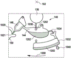
The step of releasing the seal enables the wash buffer to enter the aliquoting chamber. The method further comprises the steps of: the rotational rate of the cartridge is controlled to enable the wash buffer in the aliquoting chamber to be transferred into the connecting conduit and fill the metering chamber for the first time. The method further comprises the following steps: the rotational rate of the cartridge is controlled to transfer a first portion of the wash buffer from the metering chamber into the measurement structure through the valve and to transfer a first remaining portion back into the aliquoting chamber.
The method further comprises the steps of: the rotational rate of the cartridge is controlled to allow the wash buffer in the aliquoting chamber to transfer into the connecting conduit and fill the metering chamber a second time. The method further comprises the steps of: the rotational rate of the cartridge is controlled to transfer a second portion of the wash buffer from the metering chamber into the measurement structure through the valve and to transfer a second remaining portion back into the aliquoting chamber. The method further comprises the steps of: the rotational rate of the cartridge is controlled to allow the second portion of the wash buffer to flow across the membrane to the absorbent structure. The use of the above-described structure may be beneficial in that it may provide an accurately metered amount of wash buffer to be used in a subsequent wash step. This may also be beneficial because it is not necessary to add fluids to the kit using a pipetting system or other device in order to have multiple steps using a wash buffer.
In another embodiment, a process chamber comprises: a first specific type of binding partner for the analyte, which has a detectable label; and a second specific type of binding partner having a capture label. Both of which form a binding complex with the analyte. This may consist of a first specific type of binding partner, a second specific type of binding partner, and an analyte. This may additionally provide a measurement structure within the immobilized binding partner that is specific for the capture label of the second specific type of binding partner.
In another embodiment, the detection is fluorescence based.
In another embodiment, the label is a particle-based fluorescent label.
In another embodiment, the measurement structure comprises an optical calibration zone. The optical calibration zone may for example be an area on the measurement structure which contains a defined amount of immobilized markings and provides a means for checking whether the optics of the instrument are functioning correctly and, if not, for properly calibrating it. In other embodiments, the optical calibration zone is located at a different location on the test element.
In another embodiment, the measurement structure comprises a reagent and a flow control region. This may provide a means for checking whether the kit is functioning properly in terms of reagents and immunochromatography. There may be, for example, two different control zones (reagent/flow control zone and optical calibration zone) to serve as instrument control zones for correcting the intensity of the radiation or excitation source when making optical measurements.
In another embodiment, the measurement is of a concentration of cardiac troponin.
In another embodiment, each of the at least one reagent is dry. The use of dry reagents can be beneficial because they can be stored directly on the test element in a stable manner and still provide accurate results after storage for a long period of time.
In another embodiment, each of the at least one reagent is provided in a dry chemical formulation. The use of dry reagents can be beneficial because they can be stored directly on the test element in a stable manner and still provide accurate results after storage for extended periods of time.
In one aspect, the present invention provides a method for determining the amount of an analyte in a blood sample using a kit. The medical system includes a kit. The cartridge is operable to swivel about an axis of rotation. The kit comprises an inlet for receiving a blood sample. The kit further comprises a blood separation chamber for separating plasma from a corpuscular blood sample by centrifugation. The blood separation chamber is fluidly connected to the inlet. The kit further comprises a treatment chamber comprising at least one reagent. The at least one reagent includes at least one specific type of binding partner operable to bind to the analyte to form at least one analyte specific type of binding partner complex. The cartridge further includes a first valve structure connecting the blood separation chamber to the processing chamber. The kit further comprises a measurement structure for enabling measurement of the amount of the analyte.
The measurement structure comprises a chromatographic membrane. The chromatographic membrane comprises an immobilized binding partner for binding, directly or indirectly, to the analyte or to at least one analyte-specific binding partner complex. The measurement structure further comprises an absorber structure. The absorbent body structure is closer to the axis of rotation than the film. The cartridge further comprises a second valve structure connecting the process chamber to the measurement structure. The kit further comprises a fluid chamber filled with a wash buffer. The fluid chamber is fluidly connected to the measurement structure. The sealing section holds the washing buffer in the fluid chamber.
The kit further comprises an aliquoting chamber. The cartridge further comprises a fluid conduit connecting the fluid chamber with the aliquoting chamber. The cartridge further comprises a metering chamber. The cartridge further comprises a connecting conduit fluidly connecting the metering chamber with the aliquoting chamber. The measurement structure is connected to the metering chamber via a third valve structure. The cartridge further comprises a vent connected to the metering chamber. The vent is closer to the axis of rotation than the metering chamber.
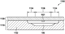
In another aspect, the metering chamber has a sidewall and a central region. The sidewalls taper away from the central region. The capillary action is greater near the side walls of the metering chamber than in the central region of the metering chamber. This may facilitate filling of the metering chamber, reducing the chance of bubbles forming in the metering chamber. This may result in more accurate metering of the fluid dispensed from the metering chamber.
In another embodiment, the metering chamber is operable to cause fluid to fill the metering chamber using capillary action. The connecting conduit includes a conduit entry port in the aliquoting chamber. The connecting conduit further comprises a conduit exit port in the metering chamber. The conduit exit is closer to the axis of rotation than the conduit entry. The connecting conduit is operable to cause fluid to flow to the metering chamber using capillary action. This embodiment may be beneficial because it may provide an accurate way for multiple aliquots of fluid to be accurately metered.
In another embodiment, the connecting conduit comprises a conduit entry port in the aliquoting chamber. The connecting conduit further comprises a conduit exit port in the metering chamber. An arc about the axis of rotation passes through both the conduit entry port and the conduit exit port. This embodiment may be beneficial as it may provide a very efficient means of providing accurately metered multiple volumes of buffer fluid.
In another embodiment, the cartridge further comprises an overflow chamber connected to the blood separation chamber. The overflow chamber includes an opening. The first siphon includes a siphon inlet in the blood separation chamber. The first siphon includes a siphon exit in the process chamber. The opening is closer to the axis of rotation than the siphon exit. The siphon inlet may be closer to the axis of rotation than the siphon outlet. This embodiment may have the following benefits: all fluid from the blood separation chamber is transferred to the processing chamber.
In another embodiment, the cartridge further comprises an overflow chamber connected to the blood separation chamber. The overflow chamber includes an opening. The first siphon includes a siphon inlet in the blood separation chamber. The first siphon includes a siphon exit in the process chamber. The opening is closer to the axis of rotation than the siphon exit. The siphon exit may be closer to the axis of rotation than the siphon entrance. This embodiment may have the following benefits: not all of the fluid from the blood separation chamber is transferred to the processing chamber. This may reduce the amount of fatty material in the plasma that is transferred to the processing chamber. This may result in a higher quality analysis than would be performed if the siphon were in a different position.
In another embodiment, the first siphon tube includes a closest location proximate the axis of rotation. The distance of the first siphon from the axis of rotation varies monotonically between the siphon inlet and the closest position. The distance of the first siphon from the axis of rotation varies monotonically between the siphon exit and the closest position.
In another embodiment, the process chamber includes at least two sub-process chambers. Each of the at least two sub-processing chambers is fluidly connected by an intermediate valve structure. The intermediate valve structure may be any of the alternative valve structure types discussed for the first or second valve structures. The process chamber contains two or more reagents. Each of the at least two sub-processing chambers includes a portion of two or more reagents. The two or more reagents may be divided into different reagent zones within each of the two sub-processing chambers, or there may be a mixture of two or more reagents within the two sub-processing chambers. This embodiment may be advantageous as it enables the plasma to be treated with different reagents in a certain sequential order. This may enable more complex tests to be performed using the cartridge. The use of two or more sub-process chambers for storing different reagents may also be advantageous if the reagents to be reacted with each other have to be stored on the cartridge, since inadvertent reaction between the reagents may be prevented by spatially dividing the different reagents into different sub-process chambers.
In another embodiment, the medical system further comprises a cartridge rotator for controlling rotation of the cartridge about the rotational axis.
In another embodiment, a medical system includes: a memory for storing machine executable instructions; and a processor for controlling the medical system. Execution of the machine-executable instructions causes the processor to: the cartridge is rotated about the axis of rotation by controlling the cartridge rotator to transport the blood sample to the blood separation chamber. Execution of the machine-executable instructions further causes the processor to: rotation of the cartridge about the axis of rotation is controlled by controlling the cartridge spinner to separate plasma from the corpuscular blood sample components by centrifugation. Execution of the machine-executable instructions further causes the processor to: the first valve structure is opened by controlling the cartridge gyrator and the cartridge is rotated about the rotational axis to transport the defined portion of the plasma from the blood separation chamber to the processing chamber. In the case where the first valve structure is a siphon, then both opening and rotation of the cartridge may be performed by controlling the cartridge gyrator. If the first valve structure is another type of valve, such as a wax or a mechanical or mechanical valve, the valve opening mechanism may be controlled by the processor to accomplish this. As are any of the other valve structures mentioned herein.
Execution of the machine-executable instructions further causes the processor to: the portion of plasma is retained in the processing chamber. This may be accomplished by controlling the cartridge gyrator. The plasma is mixed with reagents and combined with at least one specific type of binding partner to form at least one analyte specific type of binding partner complex. Execution of the machine-executable instructions further causes the processor to: the seal is released to enable the first portion of the wash buffer to enter the measurement structure. This may be performed, for example, by the processor controlling a seal opener, which is a device or mechanism that actuates the cartridge in order to open the seal.
Execution of the machine-executable instructions further causes the processor to: opening the second valve structure to transfer the at least one analyte specific binding partner complex to the measurement structure, and controlling the rotational weight of the cartridge to allow the at least one analyte specific binding partner complex to flow through the second valve structure to the measurement structure. This may be achieved, for example, by controlling the rate of rotation of the cartridge using a cartridge rotator. Execution of the machine-executable instructions further causes the processor to: the rotational rate of the cartridge is controlled by controlling the cartridge spinner to allow the at least one analyte-specific binding partner complex to flow across the membrane to the absorbent structure at a defined rate and to allow the at least one analyte-specific binding partner complex to bind to the mobile binding partner. This step may also be accomplished by the processor by controlling the rate of rotation of the cartridge using a cartridge rotator.
Execution of the machine-executable instructions also allows the processor to control the rate of rotation of the cartridge to allow the first portion of the wash buffer to flow across the membrane to the absorbent structure at a defined rate. A cartridge rotator may be used to control the rate of rotation of the cartridge. Execution of the machine-executable instructions further causes the processor to: measurements are performed using the membrane and using an optical measurement system for enabling analyte quantitation.
In another embodiment, the medical system further comprises a sealed opener. For example, the processor may be capable of automatically controlling the seal opener. Execution of the machine-executable instructions causes the processor to control the seal opener to release the seal to enable wash buffer to enter the aliquoting chamber before reducing the rotational rate of the cartridge, thereby permitting the wash buffer in the aliquoting chamber to transfer into the connecting conduit and fill the metering chamber for the first time.
In another embodiment, the first valve structure is a first siphon tube.
In another embodiment, the second valve structure is a second siphon tube.
In another embodiment, the third valve structure is a third siphon tube.
In another embodiment, the medical system further comprises an optical measurement system for performing measurements using the membrane.
In another embodiment, the optical measurement system is a fluorescence-based detector. In some examples, the fluorescence-based detector may be a spectrometer or a monochromator.
In another embodiment, the medical system further comprises a temperature controller for maintaining the temperature of the cartridge within a predetermined temperature range. This can be beneficial because the measurements and reagents can work better or at a controlled rate if the temperature is accurately controlled.
In another embodiment, the fluid chamber is contained within the cartridge.
In another embodiment, the sealing portion of the fluid chamber is a foil pierceable by a lancing structure.
In another embodiment, the fluid chamber is within a blister pack (blister pack) or blister packaging (blister pack). The blister may be depressed and the increase in pressure may cause the seal to break, thereby releasing the fluid in the fluid reservoir.
In another embodiment, the absorbent body structure is a waste absorbent fabric.
In another embodiment, the fluid chamber is a blister pack (blister pack), wherein the blister pack comprises a flexible wall. Depressing the flexible wall can cause the seal to open.
In another embodiment, the sleeve is molded or formed from plastic. There may be a lid attached to the moulded part.
In another embodiment, the blood separation chamber is also used to determine the hematocrit (hematocrit) of the blood sample after separation of the plasma from the blood corpuscular sample components is completed. In one example, this may be accomplished by optically determining: a volume filled by the corpuscular blood sample component in a portion of the blood separation chamber remote from the axis of rotation after centrifugation of the test element, and a volume filled by plasma in a portion of the blood separation chamber close to the axis of rotation after centrifugation of the test element. These two volumes can be correlated with each other to obtain a parameter related to the hematocrit of the blood sample.
In another example, analyte quantification is performed without any washing steps. Thus, the method steps detailing the control of the rotational rate of the cartridge to control the flow of the washing buffer at a defined rate across the chromatographic membrane to the absorbent structure can be deleted from the claims.
In another embodiment, the initial value for analyte quantification is generated by performing an optical measurement before washing the membrane with a wash buffer and after chromatographic analysis of the treated sample. This may give an indication for a high analyte concentration within the sample and allow an early warning to be sent to the user if the analyte amount or concentration is high.
In another example, analyte quantification is performed by using serum, plasma or urine as a sample.
For different exempt certification formats, we may also refer to US 2009/0191643 for more details.
It is to be understood that one or more of the above-described embodiments and/or examples of the invention may be combined, as long as the combined embodiments are not mutually exclusive.
It will also be understood that the method steps and/or actions performed by the processor in response to machine-executable instructions may be performed in a different order, so long as the rearrangement does not result in an action or contradictory order of method steps. In particular, the following two steps (and equivalent actions performed by the processor) may be performed before releasing the seal to enable the first portion of the wash buffer to enter the measurement structure: opening the second valve structure to transfer the at least one analyte specific binding partner complex to the measurement structure and controlling the rotational rate of the cartridge to allow the at least one analyte specific binding partner complex to flow through the second valve structure to the measurement structure and controlling the rotational rate of the cartridge to allow the at least one analyte specific binding partner complex to flow across the membrane to the absorbent structure at a defined rate and to allow the at least one analyte specific binding partner complex to bind to the immobilized binding partner.
It should also be understood that the method steps and/or actions performed by the processor in response to machine-executable instructions are not limited to the particular ordering as described above and defined in the claims.
Drawings
Embodiments of the invention are explained in more detail below, by way of example only, with reference to the accompanying drawings, in which:
FIG. 1 illustrates an example of a kit;
FIG. 2 shows a further view of the cartridge of FIG. 1;
FIG. 3 shows a further view of the cartridge of FIG. 1;
FIG. 4 shows an alternative to the components illustrated in FIG. 3;
FIG. 5 shows an alternative to the process chamber illustrated in FIG. 1;
FIG. 6 shows a symbolic diagram illustrating the principle of how a kit may be used to determine a quantitative analyte;
FIG. 7 illustrates an example of an automated analyzer;
FIG. 8 shows a flow chart illustrating a method of operating the automatic analyzer of FIG. 7;
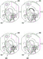
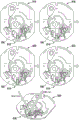
FIGS. 9A, 9B and 9C diagrammatically illustrate a method of determining the amount of an analyte in a blood sample using the kit of FIG. 1;
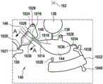
FIG. 10 illustrates a metering structure for performing multiple aliquots of a fluid;
FIG. 11 illustrates a cross-sectional view of the metering chamber;
FIG. 12 illustrates a portion of a method of performing dispensing of a fluid using the metering structure of FIG. 10;
FIG. 13 further illustrates a portion of a method of performing dispensing of a fluid using the metering structure of FIG. 10;
FIG. 14 further illustrates a portion of a method of performing dispensing of a fluid using the metering structure of FIG. 10;
FIG. 15 further illustrates a portion of a method of performing dispensing of a fluid using the metering structure of FIG. 10;
FIG. 16 further illustrates a portion of a method of performing dispensing of a fluid using the metering structure of FIG. 10;
FIG. 17 further illustrates a portion of a method of performing dispensing of a fluid using the metering structure of FIG. 10;
FIG. 18 further illustrates a portion of a method of performing dispensing of a fluid using the metering structure of FIG. 10;
FIG. 19 illustrates an alternative metering structure for performing multiple aliquots of a fluid;
FIG. 20 illustrates a portion of a method of performing dispensing of a fluid using the metering structure of FIG. 19;
FIG. 21 further illustrates a portion of a method of performing dispensing of a fluid using the metering structure of FIG. 19;
FIG. 22 further illustrates a portion of a method of performing dispensing of a fluid using the metering structure of FIG. 19;
FIG. 23 further illustrates a portion of a method of performing dispensing of a fluid using the metering structure of FIG. 19;
FIG. 24 further illustrates a portion of a method of performing dispensing of a fluid using the metering structure of FIG. 19;
FIG. 25 further illustrates a portion of a method of performing dispensing of a fluid using the metering structure of FIG. 19; and
FIG. 26 further illustrates a portion of a method of performing dispensing of a fluid using the metering structure of FIG. 19.
Detailed Description
Like-numbered elements in the figures are equivalent elements or perform the same function. Elements that have been previously discussed will not necessarily be discussed in subsequent figures if they are functionally equivalent.
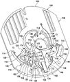
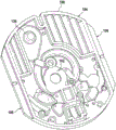
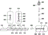
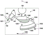
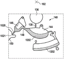
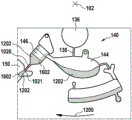
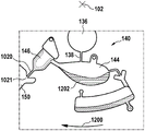
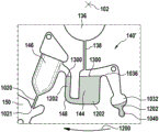
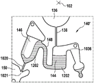
Fig. 1 and 2 show an example of a kit 100. Fig. 1 shows a front view of the cartridge 100. Fig. 2 shows a back side view of the cartridge 100. The cartridge is adapted to rotate about an axis of rotation 102. The cartridge 100 body is flat and has an outer edge perpendicular to the axis of rotation 102. The outer edge 104 is less than a certain radius and the shape body is circular. In the embodiment shown in fig. 1 and 2, there are also several optional flat portions 106 of the outer edge. These may help hold or store the sleeve 100. In an alternative embodiment, such flat portions are absent and the overall outer edge of the sleeve is shaped body circular. The kit 100 may be made, for example, of molded plastic. There may be a cover placed on the surface of the structure shown in fig. 1. The cover is not shown to facilitate viewing of the microfluidic structures within the cartridge 100.
The cartridge 100 is shown having a blood inlet 108 where a blood sample may be added to or pipetted into the cartridge 100. The blood inlet 108 may, for example, comprise a storage chamber 110 for storing a volume of a blood sample. Reservoir chamber 110 is shown as having an extension chamber 112 with a vent 114. Various microfluidic structures are also shown having an extension chamber 112 and a vent 114. There is also a fail-safe indicator 116, which is a fluid-filled region of the microfluidic structure to indicate that the microfluidic structure has received a sufficient amount of fluid or sample. These may be optically inspected, for example, during use of the kit 100. In some cases, these are labeled, but are not discussed herein. The blood inlet 108 is shown fluidly connected to a blood separation chamber 118. The blood separation chamber 118 is used to separate plasma from blood corpuscular blood sample components (blood cells) in a blood sample. Blood separation chamber 118 is also shown connected to an overflow chamber 120, overflow chamber 120 receiving excess plasma from the blood sample. The function of the blood separation chamber 118 will be described in more detail below. The blood separation chamber 118 is connected to a process chamber 124 via a first valve structure 122.
In this example, the first valve structure 122 is a siphon. However, it may comprise other structures, such as mechanical, magnetic or thermally activated valves. The process chamber 124 is shown as containing several surfaces 126 that may be used to store dry reagents. In other examples, there may be a large amount of liquid or other type of reagent that may be mixed with the plasma sample. The process chamber 124 is shown connected to a measurement structure 130 via a second valve structure 128. In this example, the second valve structure 128 is a siphon tube. The second valve structure 128 may take any of the forms that the first valve structure 122 may also take. In this example, the process chamber 124 is shown as a single chamber. In another example, the processing chamber 124 may include several sub-chambers such that plasma samples may be processed sequentially with different reagents. The measurement structure 130 is shown as containing a chromatographic membrane 134 and a further absorbent body structure 132, the absorbent body structure 132 contacting one end of the chromatographic membrane closer to the axis of rotation, the absorbent body structure 132 acting as a waste absorbing fabric (waste sheet). The reagents and chromatographic membrane 134 are discussed in more detail below.
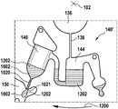
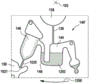
After treatment with the reagent, the plasma sample may be wicked or transported across the chromatographic membrane 134. Before and/or after this, a wash buffer may be used to prepare or wash the chromatographic membrane 134. The kit 100 shown in fig. 1 and 2 is a kit that includes a number of different optional features. Fluid chambers 136 are shown on the back side of the cartridge 100. In this example, the fluid chamber 136 is a blister pack or flexible fluid chamber that may be compressed from the exterior of the cartridge 100. When fluid chamber 136 is compressed, the seal is broken, which allows fluid within fluid chamber 136 to enter fluid conduit 138. Fluid conduit 138 then carries the fluid to metering structure 140.
The metering structure 140 enables multiple supplies of wash buffer to the measurement structure 130 in accurately measured amounts. However, the metering structure 140 is not required. There may be examples where the wash buffer is delivered directly to the measurement structure 130. In other examples, the measurement structure is not previously treated with a wash buffer prior to performing the test. The structure labeled 136' is an alternative fluid chamber. Fluid chamber 136 'may be mechanically actuated to break the seal around its periphery, which results in fluid entering metering structure 140 via fluid conduit 138'. The kit 100 is also shown as containing another optional structure. The structure labeled 142 is a manual fill position where reagents or buffer solutions can be added to the measurement structure 130 manually or through an external source (e.g., a dispenser).
The metering structure 140 is shown as containing an aliquoting chamber 144. Aliquoting chamber 144 receives fluid from fluid chamber 136 or 136'. Aliquoting chamber 144 is connected to metering chamber 146 via connecting conduit 148. The metering structure 146 is used to accurately meter the buffer fluid and supply the metered aliquots of fluid to the measurement structure 130 one or more times. The metering structure 146 is connected to the measurement structure 130 via a fluid element 150. In this case, the fluidic element 150 is shown as containing a microfluidic conduit or channel and a chamber to accommodate an amount of buffer fluid when it is metered. The function of the metering structure 140 and several alternatives will be discussed with reference to later figures.
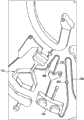
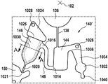
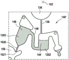
Fig. 3 shows an enlarged region of fig. 1 illustrating the blood separation chamber 118 and the processing chamber 124 in more detail. The separation chamber 118 is shown as including an upper portion 300 and a lower portion 302. The upper portion 300 is closer to the axis of rotation 102. The overflow chamber is shown with an overflow opening 304. The overflow opening 304 sets the maximum volume of fluid within the blood separation chamber 118. In this example, the first valve structure 122 is a siphon. It may also be referred to as a first siphon. The first siphon 122 has a siphon inlet 306 in the blood separation chamber 118. The first siphon tube 122 also has a siphon exit 308 into the extension chamber 112'. In this example, there is an additional extension chamber 112' located between the blood separation chamber 118 and the processing chamber 124. In other examples, the siphon exit 308 may be directly connected to the process chamber 124.
The extension chamber 112 enables the process chamber 124 to be positioned further from the axis of rotation. This may provide additional space for the process chamber 124 in some instances. Upon careful inspection of FIG. 3, it can be seen that siphon exit 308 is closer to axis of rotation 102 than siphon entry 306. This is done because it captures an additional amount of plasma within the upper portion 300. The last little or the last amount of plasma may comprise fatty or oily tissue contained in the plasma. Placing the siphon exit 308 closer to the axis of rotation 102 may reduce the amount of such material in the plasma that is eventually transferred to the processing chamber 124. This may result in a more excellent or accurate measurement of the analyte.
It can be seen that the first siphon tube 122 has a closest position 310 to the axis of rotation 102. Between the closest location 310 and the siphon exit 308, the distance to the axis of rotation 102 increases monotonically.
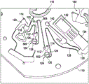
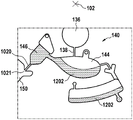
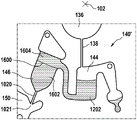
Fig. 4 shows a further enlarged region of the sleeve 100. The area of fig. 4 is the same as the area of fig. 3. In the example shown in fig. 4, the first and second valve structures 122, 128 have been modified. The first valve structure 122 includes a valve element 400 and the second valve structure 128 includes a valve element 402. Valve elements 400 and 402 may be mechanical valves that may be opened and/or closed by a variety of means. For example, the valve elements 400, 402 may be mechanically actuated, they may comprise thermally melted wax or other material, they may be magnetically operated, or actuated using other means.
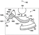
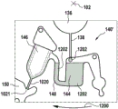
Fig. 5 shows a modification of the kit 100 shown in fig. 1. In the example shown in fig. 5, the process chamber 124 has been broken down into two separate sub-chambers 500 and 502. The first valve structure 122 is connected to the first sub-chamber 500. There is then an intermediate valve structure 504 between the first sub-chamber 500 and the second sub-chamber 502. The second valve structure 128 is then connected from the second sub-chamber 502 to the measurement structure 130. The two sub-chambers 500, 502 may be used to sequentially process plasma with different reagents.
Fig. 6 shows a symbolic diagram illustrating the principle how a kit may be used to determine a quantitative analyte. 600 represents a blood sample, and 602 represents an analyte present in the blood 600. Arrow 604 indicates the generation of plasma by centrifugation. 602' represents an analyte 602 in plasma. Arrow 606 represents the mixing of the plasma with the dry assay reagents and incubation in the processing chamber. And 124, a process chamber. In the process chamber, capture antibodies (capture antibodies) 608 and detection antibodies 610 are attached to the analyte 602' in the plasma. The combination of the capture antibody 608 and the detection antibody 610 with the analyte 602' forms an analyte-specific binding partner complex 611. Arrow 609 indicates transport to the measurement structure.
When used with the kit of fig. 1, the protocol illustrated in fig. 6 may in some instances provide better measurements than when using standard laboratory methods. For example, the concentration of cardiac troponin is tested using an equivalent microfluidic structure in a disc (disc). The results of these tests show that the accuracy and reproducibility of the measurements are superior to those obtained in a typical analytical laboratory.
In an embodiment, the antibody which can be used for detecting human cardiac troponin T is an antibody which recognizes the linear epitope E L VS L KD at amino acid position 129 of the human cardiac troponin (P45379, UniProt database), or an antibody which recognizes the linear epitope QQRIRNEREKE of the human cardiac troponin (P45379, UniProt database) at amino acid position 147 of the P45379 (UniProt database), or an antibody which recognizes the linear epitope QQRIRNERE of the human cardiac troponin (P45379, UniProt database) at amino acid position 147 of the P45379 (UniProt database), or an antibody which recognizes the linear epitope QQRIRNERE of the human cardiac troponin (P45379, UniProt database) at amino acid position 147 of the P45379 (UniProt database). in an embodiment, these antibodies are murine monoclonal antibodies, in the linear epitope binding form of the human cardiac troponin T-binding protein T-detecting the linear epitope binding protein at amino acid position 4537135 of the linear epitope binding protein (P4537129) at the linear epitope binding protein (P4537157 at amino acid position 45379, the linear epitope binding protein library of the linear epitope binding protein (P45379) of the linear epitope binding protein library 379, the linear epitope binding protein (P45379, the linear epitope binding protein library 37157 of the linear epitope binding protein (P45379, the UniProt 379, the linear epitope binding protein library of the linear epitope binding protein (P45379, the linear epitope binding protein library) at amino acid position 147 of the linear epitope binding protein (P45379, the linear epitope binding protein library 379, the linear epitope binding protein library 37135 of the linear epitope binding protein library of the linear epitope binding protein (P45379, the linear epitope binding protein library of the linear epitope 379, the linear epitope binding protein (P45379) at amino acid position 147 of the linear epitope 379, the linear epitope binding protein library of the linear epitope 379 library of the linear epitope binding protein library of the linear epitope 379, the linear epitope binding protein library of the protein of the linear epitope 379, the.
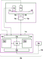
Fig. 7 shows an example of a medical system 700. The medical system 700 is adapted to receive the cartridge 100. There is a cartridge rotator 702, the cartridge rotator 702 being operable for rotating the cartridge 100 about an axis of rotation. The cartridge rotator 702 has a motor 704 attached to a clamp 706 that is attached to a portion of a cartridge 708. The kit 100 is also shown as having a measuring or transparent structure 710. The cartridge 100 may be rotated such that the measurement structure 710 travels in front of the optical measurement system 712, which optical measurement system 712 may perform, for example, optical measurements on a quantity of analyte. An actuator 711 is also shown in this figure. Which may be used to unseal the fluid reservoirs in the cartridge 100. There may also be additional actuators or mechanisms for actuating the mechanical valves or valve elements on the cartridge, if they are present.
The actuator 711, cartridge spinner 702, and measurement system 712 are all shown connected to a hardware interface 716 of a controller 714. Controller 714 includes a processor 718 in communication with a hardware interface 716, electronic storage 720, electronic storage 722, and a network interface 724. Electronic storage 730 has machine-executable instructions that enable processor 718 to control the operation and functions of medical system 700. The electronic storage 720 is shown as containing measurements 732 that are taken when the instructions 730 are executed by the processor 718. The network interface 724 enables the processor 718 to send measurements 732 to the laboratory information system 728 via the network connection 726.
Fig. 8 shows a flow chart illustrating a method of operating the medical system 700 of fig. 7. The steps in fig. 8 may be, for example, machine executable instructions included in instructions 730. Prior to performing the method of fig. 8, a blood sample may be placed into the inlet, for example, and the cartridge 100 is then placed into the medical system 700. First, in step 800, the processor 718 controls the motor 704 such that the cartridge rotates about an axis of rotation to transport the blood sample into the blood separation chamber. Next, in step 802, the processor 718 further controls the motor 704 such that rotation of the cartridge about the axis of rotation separates plasma from the corpuscular blood sample components by centrifugation. Next, in step 804, the processor 718 controls the motor 704 such that the first valve structure opens and the cartridge rotates about the axis of rotation at a sufficient speed to transport the defined portion of plasma from the blood separation chamber to the processing chamber. In the case where the valve structure includes mechanical valve elements, there may be additional mechanisms or devices that the processor 718 controls to open the mechanical valve elements.
Next, in step 806, the processor 718 controls the rotation rate of the motor 704 such that the portion of the plasma is maintained in the processing chamber. During this time, the plasma is mixed with reagents and combined with at least one specific type of binding partner to form at least one analyte specific type of binding partner complex. Next, in step 808, the seal is released by the processor 718 to enable the first portion of the wash buffer to enter the measurement structure. For example, the processor 718 may control the actuator 711 to compress the fluid chamber 136 shown in fig. 2. Next, in step 810, processor 718 controls the rate of rotation of motor 704 such that the second valve structure is opened to transfer the at least one analyte-specific binding partner complex to the measurement structure and such that the cartridge allows the at least one analyte-specific binding partner complex to flow through the second valve structure to the measurement structure. Again, if the second valve structure includes a mechanical valve element, the processor may also control another device or mechanism to open this mechanical valve element.
Next, in step 812, processor 718 controls the rate of rotation of motor 704 such that the cartridge allows the at least one analyte specific binding partner complex to flow across the membrane to the absorbent structure at a defined rate and allows the at least one analyte specific binding partner complex to bind to the immobilized binding partner. In step 814, the processor 718 controls the rate of rotation of the motor 704 such that the cartridge spins at a rate that allows the first portion of the wash buffer to flow across the membrane to the absorbent structure at a defined speed. In an alternative embodiment, step 808 (releasing the seal to enable the first portion of the wash buffer to enter the measurement structure) is performed, followed by step 814 directly.
Finally, in step 816, the processor 718 controls the optical measurement system 712 to perform measurements using the optical measurement system. This measurement 732 can then be converted to an analyte amount or concentration.
Fig. 9A, 9B, and 9C diagrammatically illustrate a method of determining the amount of an analyte in a blood sample using the kit 100. The method is illustrated diagrammatically in fig. 9A, 9B and 9C. Image 900 shows the sleeve 100 in its initial condition. Next, in step 902, blood is placed into the inlet. Next, in step 904, the blood sample is transferred to a blood separation chamber. In step 906, the plasma is separated from the red blood cells by centrifugation. Next, in step 908, the plasma is transferred to a processing chamber. Next, in step 910, the plasma is mixed with a reagent. In step 912, the wash buffer is released by breaking the seal. In step 914, the culture or combination of plasma and reagent is transferred to a measurement structure.
Next, in step 916, chromatographic analysis of the analyte specific binding partner complex or culture is performed. Next, in step 918, the wash buffer is metered. In several examples, the depicted structures can be used to provide multiple dosing of wash buffer. However, this is not necessary in all cases and it is possible to transfer only the fluid from the fluid chamber and that there is no metering step. Next, in step 920, the wash buffer is transferred to the measurement structure and wicked across the chromatographic membrane 134 into the absorbent body structure 132, as shown in step 922. Finally, in step 924, a measurement of the analyte is performed using the fluorescence measurement.
Fig. 10 shows an example of a metering structure 140. The metering structure is part of the fluid components that make up the cartridge 100 as shown in fig. 1. There is a rotation axis, labeled 102. Also shown in this figure is a portion of the fluid chamber 136. The fluid chamber is designed to have a reservoir that provides fluid via a fluid chamber conduit 138 that leads into aliquoting chamber 144. In this example, the aliquoting chamber 144 is whale-like. There is a connecting conduit 148 connecting the aliquoting chamber 144 with the metering chamber 146. The connecting conduit 148 has a conduit entry port 1014 and a conduit exit port 1016. Conduit entry port 1014 opens into aliquoting chamber 144 and conduit exit port 1016 opens into metering chamber 146. An arc 1018 drawn about axis of rotation 102 passes through both conduit entry port 1014 and conduit exit port 1016. Metering chamber 146 is connected to fluid element 150 via tubular structure 1020. In this example, there is a valve 1021 between the tubular structure 1020 and the metering chamber 146. In this example, the valve 1021 is a capillary valve.
The valve 1021 may be implemented in different ways. In some alternatives, the shape of the interface between the tubular structure 1020 and the fluidic element 150 may act as a capillary valve. Alternatively, a valve may be placed between elements 1020 and 150. In other embodiments, the conduits may be connected in the same location and controllable microvalves may be used instead. The controllable microvalve may be placed between the metering chamber 146 and the tubular structure 1020, or between the tubular structure 1020 and the fluid element 150.
Aliquoting chamber 144 is also shown to have a connection to a fluid connection 1034, which leads from fluid connection 1034 to a excess fluid chamber 1032. Fluid connection 1034 has a fluid connection inlet 1036. Fluid connection inlet 1036 defines a maximum fluid level in aliquoting chamber 144. The maximum fluid level in aliquoting chamber 144 is below arc 1018. In this embodiment, fluid connection 1034 is connected to excess fluid chamber 1032 via capillary valve 1038. The use of valves or capillary valves is optional. The excess fluid chamber is shown with a vent 1028, and it is also connected to the failsafe chamber 1040. When fluid flows into excess fluid chamber 1032, fail-safe chamber 1040 fills. The defeat-fail-safe chamber 1040 may be used to optically indicate whether fluid has entered the excess fluid chamber 1032. For example, during use, if fail-safe chamber 1040 is not filled, it may indicate that aliquoting chamber 144 is not properly filled with fluid.
Fig. 11 shows a cross-sectional view 1100 of section a-a labeled 1030 in fig. 10. In this figure, the body of the sleeve 1102 is visible. An opening for the metering chamber 146 is present in the body 1102. In this example, the body of the sleeve 1102 is manufactured by injection molding. The body of the kit is assembled from a cover (lid) 1108 and a support structure 1110.
At the distal end of the metering chamber, an entry port into the valve 1021 can be seen. The metering chamber 146 may be considered to be divided into several distinct regions. On the edges, there are two sidewall regions 1104. Between the two sidewall regions or two side regions is a central region 1106. The sidewall regions 1104 become narrower or tapered away from the central region 1106. This results in a narrowing of the size of the metering chamber 146 in this region. Thus, the capillary action in the sidewall region 1104 is higher than the capillary action in the central region 1106. This may result in metering chamber 146 filling with fluid first in sidewall region 1104 prior to central region 1106. This may have the following benefits: when metering chamber 146 is filled with fluid, the number of bubbles formed or trapped in metering chamber 146 is reduced.
Fig. 12-18 illustrate how metering structure 140 may be used to perform multiple aliquots of fluid to fluid elements 150.
In fig. 12, the disk rotates about an axis of rotation 102. Arrow 1200 indicates the direction of rotation. In this particular example, the disk revolves at 20 Hz. Fluid or wash buffer 1202 is transported from fluid chamber 136 into aliquoting chamber 144. Fluid 1202 can be seen dripping from fluid conduit 138 into aliquoting chamber 144. The volume of fluid in aliquoting chamber 144 is limited by, and thus metered by, fluid connection 1034, which is connected to excess fluid chamber 1032. The failsafe chamber 1040 may be considered to be filled with fluid.
Next, in fig. 13, fluid volume 1202 has been completely transferred from fluid chamber 136 into aliquoting chamber 144. The failsafe chamber 1040 is shown filled with a fluid. In this example, the disk still revolves at the same rate as shown in fig. 12. Aliquoting chamber 144 is filled with fluid 1202 up to a maximum fluid level 1300. It can be seen that the maximum fluid level 1300 is below the connecting conduit 148, or farther from the axis of rotation 102 than the connecting conduit 148. When the disk is rotated around in this manner, fluid 1202 may not enter metering chamber 146.
Next, in fig. 14, the disk is stopped or decelerated to a lower rotation frequency, wherein the high deceleration rate is for example at 50 Hz/sec. The inertia of the fluid forces the fluid 1202 toward and through the connecting conduit 148 and into the metering chamber 146. It can be seen in this figure that fluid 1202 fills the sides of metering chamber 146 before it fills the central region. This is due to the tapered sidewalls 1104 shown in fig. 11. Capillary action results in this sidewall portion of metering chamber 146 filling first. This manner of filling the metering chamber may reduce the chance of bubbles forming or clinging to metering chamber 146.
In fig. 15, the cartridge is still stationary, or at a reduced rate of rotation, and the metering chamber 146 is completely filled with fluid 1202. The sleeve or disc may still be considered to be stationary. The complete filling of the metering chamber is caused by capillary forces, which are caused by the respective geometry of the metering chamber.
Fig. 16 shows the same view as shown in fig. 15, except that a dashed line 1600 has been drawn in the metering chamber 146. This line 1600 in the metering chamber 146 divides the fluid in the metering chamber into portions or portions. A portion 1604 of the fluid radially inward (closer to the axis of rotation 102) from the line 1600 may flow back into the reservoir. The radially outward portion (further from the axis of rotation 102) or portion 1602 may be completely diverted into the fluid element 150. The radially inward portion 1604 may be referred to as the remaining portion of the fluid and the radially outward portion 1602 may be referred to as the fluid portion 1602 that is diverted into the downstream fluidic element. The fluid volume 1602 is an aliquot that is transferred to the fluidic element 150 in a subsequent step.
Next, in fig. 17, the disc begins to accelerate and turn around in direction 1200. The disc is accelerated; this causes capillary valve 1021 to open. The remaining portion 1604 of the fluid is transferred back to aliquoting chamber 144. Fluid portion 1602 is in the process of being transferred to fluidic element 150. A drop of fluid can be seen falling from tube 1020.
Next, in fig. 18, it can be seen that fluid volume 1602 has been completely transferred to fluidic element 150 and is no longer visible in the drawing. The remaining portion 1604 of the fluid has been transferred back into aliquoting chamber 144 and mixed with the remaining fluid 1202. The first equally dividing step is completed; the process may be repeated again from fig. 14, and may be repeated until the volume 1202 of fluid in aliquoting chamber 144 is less than the volume of metering chamber 146.
Fig. 19 shows an example of an alternative metering structure 140'. The metering structure 140' may replace the metering structure 140 of fig. 1. The mechanical structure of the metering structure 140' is similar to the metering structure 140 of fig. 10 with several mechanical differences. Again, there is a rotational axis labeled 102. Also shown in the figure is a portion of the fluid chamber 136. The fluid chamber 136 has a reservoir that provides fluid via a fluid chamber conduit 138 that leads into an aliquoting chamber 144. In this example, the aliquoting chamber 144 is in the shape of a teapot. There is a connecting conduit 148 connecting the aliquoting chamber 144 with the metering chamber 146. The connecting conduit 148 has a conduit entry port 1014 and a conduit exit port 1016. Conduit entry port 1014 opens into aliquoting chamber 144 and conduit exit port 1016 opens into metering chamber 146. The conduit entry 1014 is further from the axis of rotation 102 than the conduit exit 1016 connecting the conduits 148.
Aliquoting chamber 144 may be shown as also having a vent 1028. In this embodiment, the area around the conduit entry port 1014 is funnel shaped. It may also be noted that aliquoting chamber 144 is shown without sharp edges. The lack of a sharp edge helps to facilitate the movement of fluid from the aliquoting chamber 144 to the catheter access port 1014 as the disk decelerates.
Aliquoting chamber 144 is also shown to have a connection to a fluid connection 1034, which leads from fluid connection 1034 to a excess fluid chamber 1032. Fluid connection 1034 has a fluid connection inlet 1036. Fluid connection inlet 1036 defines a maximum fluid level in aliquoting chamber 144. The maximum fluid level in the aliquoting chamber 144 is farther from the axis of rotation 102 than the conduit exit 1016. In this example, fluid connection 1034 connects to excess fluid chamber 1032. The use of valves or capillary valves is optional. The excess fluid chamber is shown with a vent 1028, and it is also connected to the failsafe chamber 1040. When fluid flows into excess fluid chamber 1032, fail-safe chamber 1040 fills. The failsafe chamber 1040 may be used to optically indicate whether fluid has entered the excess fluid chamber 1032. For example, during use, if fail-safe chamber 1040 is not filled, it may indicate that aliquoting chamber 144 is not properly filled with fluid.
Fig. 20-26 illustrate how metering structure 140' may be used to perform multiple aliquots of fluid to fluid elements 150.
First, in fig. 20, fluid has been added to the fluid chamber 136. The cartridge is then rotated about the axis of rotation 102. This forces the fluid wash buffer 1202 to travel through the first conduit 106 into the aliquoting chamber 144. The fluid 1202 then fills the aliquoting chamber 144 and the corresponding radially outward portion of the connecting conduit 148 with fluid.
Fig. 21 shows the ferrule spinning at the same rate and in the same direction 1200 as shown in fig. 20. In fig. 21, all fluid has flowed from the fluid chamber 136. The fluid 1202 may be shown filling the connection conduit 148 and aliquoting chamber 144 to a maximum fluid level 1300 set by the fluid connection inlet 1036. Excess fluid 1202 may be shown filling excess fluid chamber 1032 and fail-safe chamber 1040.
Next, in fig. 22, the disk stops or decelerates to a lower rotational frequency. Capillary action in connecting conduit 148 and metering chamber 146 is shown initiating the draw of fluid into metering chamber 146. Fluid 1202 first fills the perimeter or edge of metering chamber 146. This is due to the tapered sidewalls 1104 shown in fig. 11. Capillary action results in the sidewall portion of metering chamber 146 being filled first. This helps prevent air bubbles from forming or clinging to metering chamber 146. The inertia of fluid 1202 may also assist the cartridge in entering metering chamber 146 as it decelerates rapidly.
Next, in fig. 23, the cartridge is shown still stationary, or at a reduced rate of rotation, and metering chamber 146 is completely filled with fluid 1202. The sleeve or disc may still be considered to be stationary.
Fig. 24 shows the same view as shown in fig. 23, except that a dashed line 1600 has been drawn in the metering chamber 146. This line 1600 in the metering chamber 146 divides the fluid in the metering chamber into portions or portions. A portion of the fluid volume 1604 or the entire fluid volume 1604 radially inward (closer to the axis of rotation 102) from the line 1600 may flow back into the reservoir. A radially outward portion (further from the axis of rotation 102) or portion 1602 may be transferred into the fluid element 150. The radially inward portion 1604 may be referred to as the remaining portion of the fluid and the radially outward portion 1602 may be referred to as the fluid portion 1602 that is diverted into the fluidic element 150. The fluid volume 1602 is aliquotable.
Next, in fig. 25, the disc begins to accelerate and turn in direction 1200. The disc is accelerated; this causes capillary valve 1021 to open. The remaining portion 1604 of the fluid is transferred back to aliquoting chamber 144. Fluid portion 1602 is in the process of being transferred to downstream fluidic element 150. A drop of fluid 1202 can be seen falling from tubular structure 1020.
Next, in fig. 26, it can be seen that fluid volume 1602 has been completely transferred to fluidic element 150 and is no longer visible in fig. 26. The remaining portion 1604 of the fluid has been transferred back into aliquoting chamber 144 and mixed with the remaining fluid 1202. The first equally dividing step is completed; the process may be repeated again from fig. 22, and may be repeated until the volume 1202 of fluid in aliquoting chamber 144 is less than the volume of metering chamber 146.
List of reference numerals
100 case
102 axis of rotation
104 circular outer edge
106 flat outer edge
108 blood inlet
110 storage chamber
112 extension chamber
112' extension chamber
114 vent
116 fail safe indicator
118 blood separation chamber
120 overflow chamber
122 first valve structure
124 process chamber
126 for the surface of reagents
128 second valve arrangement
130 measurement structure
132 absorbent body structure
134 chromatographic analysis membrane
136 fluid chamber
136' fluid chamber
138 fluid conduit
138' fluid conduit
140 metering structure
140' metering structure
142 manual fill position
144 aliquoting chamber
146 metering chamber
148 connecting conduit
150 fluidic element
300 upper part
302 lower part
304 overflow opening
306 siphon inlet
308 siphon pipe outlet
310 closest position
400 valve element
402 valve element
500 first sub-chamber
502 second sub-chamber
504 intermediate valve structure
600 blood
602 analytes in blood
602' analytes in plasma
604 plasma generation
606 mix the plasma with the dry assay reagents and incubate in the process chamber
608 Capture antibody
609 to the measurement structure
610 detection antibody
611 analyte specific binding partner complexes
612 movement of plasma across a membrane
614 Capture and detection zone
616 instrument control area
618 assay control zone
620 Capture elements
622 Artificial analyte line
700 medical system
702 sleeve gyrator
704 motor
706 clamp
708 part of a sleeve
710 measurement structure
711 actuator
712 optical measurement system
714 controller
716 hardware interface
718 processor
720 electronic storage device
722 electronic memory
724 network interface
726 network connection
728 laboratory information system
730 executable instructions
732 measured values
800 rotating the cartridge about an axis of rotation to transport a blood sample into a blood separation chamber
802 controlling rotation of the cartridge about an axis of rotation to separate plasma from corpuscular blood sample components by centrifugation
804 opens the first valve structure and rotates the cartridge about the axis of rotation to transport the defined portion of plasma from the blood separation chamber to the processing chamber
806 retain the portion of plasma in the processing chamber
808 release the seal to enable a first portion of the wash buffer to enter the measurement structure
810 opening the second valve structure to transfer the at least one specific type of binding partner complex to the measurement structure, and controlling the rotational rate of the cartridge to allow the at least one analyte specific type of binding partner complex to flow through the second valve structure to the measurement structure
812 controlling the rotational rate of the cartridge to allow the at least one analyte specific binding partner complex to flow across the membrane to the absorbent structure at a defined rate and to allow the at least one analyte specific binding partner complex to bind to the immobilized binding partner
814 control the rotational rate of the cartridge to allow the first portion of the wash buffer to flow across the membrane to the absorbent structure at a defined rate
816 performing measurements for enabling analyte quantification using a membrane and using an optical measurement system
900 set box is in initial condition
902 placing blood into an inlet
904 transferring the sample to a blood separation chamber
906 separation of plasma by centrifugation
908 transfer plasma to the processing chamber
910 mixing the plasma with a reagent
912 Release Wash buffer
914 transfer of the culture to a measurement structure
916 subjecting the analyte specific binding partner complex to chromatographic analysis
918 Wash buffer metering
920 transfer Wash buffer
922 chromatography of the washing buffer
924 measurement of analytes
1014 catheter access port
1016 duct exit
1018 arc
1020 tubular structure
1021 valve
1024 extension chamber
1026 Upper edge
1028 air vent
1030 cutting plane A-A
1032 excess fluid chamber
1034 fluid connection
1036 fluid connection inlet
1038 capillary valve
1040 failure safety chamber
1100 cross-sectional view A-A
1102 casing main body
1104 side wall
1106 central region
1108 cover
1110 support structure
1200 direction of rotation
1202 fluid
1300 maximum fluid level
1600 division line
1602A portion of a fluid
1604 the remainder of the fluid.
Claims (13)
1. A method of determining an amount of an analyte (602, 602') in a blood sample (600) using a cartridge (100), wherein the cartridge is operable to revolve around a rotation axis (102), wherein the cartridge comprises:
-an inlet (108), the inlet (108) for receiving the blood sample;
-a blood separation chamber (118), the blood separation chamber (118) for separating plasma from the blood sample, wherein the blood separation chamber is fluidly connected to the inlet;
-a process chamber (124), said process chamber (124) comprising at least one reagent comprising at least one specific type of binding partner (608, 610), said at least one specific type of binding partner (608, 610) being operable to bind to said analyte to form at least one analyte specific type of binding partner complex (611);
-a first valve structure (122), the first valve structure (122) connecting the blood separation chamber to the processing chamber;
-a measurement structure (130) for enabling a measurement of the amount of the analyte, wherein the measurement structure comprises a chromatographic membrane (134), wherein the chromatographic membrane (134) comprises an immobilized binding partner (620) for directly or indirectly binding the analyte or the at least one analyte-specific binding partner complex, wherein the measurement structure further comprises an absorbent body structure (132), wherein the absorbent body structure (132) is closer to the axis of rotation than the membrane;
-a second valve arrangement (128), the second valve arrangement (128) connecting the process chamber to the measurement arrangement;
-a fluid chamber (136, 136 '), the fluid chamber (136, 136') being filled with a washing buffer (1202), wherein the fluid chamber is fluidly connected to the measurement structure, wherein a seal holds the washing buffer within the fluid chamber;
-an aliquoting chamber (144);
-a fluid conduit (138), the fluid conduit (138) connecting the fluid chamber with the aliquoting chamber;
-a metering chamber (146);
-a connecting conduit (148), the connecting conduit (148) fluidly connecting the metering chamber with the aliquoting chamber, wherein the measuring structure is connected to the metering chamber via a third valve structure; and
-a vent (114, 1028), the vent (114, 1028) being connected to the metering chamber, wherein the vent is closer to the axis of rotation than the metering chamber;
wherein the method comprises the steps of:
-placing the blood sample into the inlet;
-rotating the cartridge about the axis of rotation to transport the blood sample into the blood separation chamber;
-controlling the rotation of the cartridge about the rotation axis to separate plasma in the blood sample from corpuscular blood sample components in the blood sample by centrifugation;
-opening the first valve structure and rotating the cartridge about the axis of rotation to transport the defined portion of the plasma from the blood separation chamber to the processing chamber;
-retaining a portion of the plasma in the processing chamber, wherein the plasma mixes with the reagent and combines with the at least one specific type of binding partner to form the at least one analyte specific type of binding partner complex;
-releasing the seal to enable a first portion (1602) of the wash buffer to enter the measurement structure, wherein the step of releasing the seal enables the wash buffer to enter the aliquoting chamber;
-controlling the rotational rate of the cartridge to permit the transfer of the wash buffer in the aliquoting chamber into the connecting conduit and the first filling of the metering chamber;
-opening the second valve structure to transfer the at least one analyte specific binding partner complex to the measurement structure, and controlling the rotational rate of the cartridge to allow the at least one analyte specific binding partner complex to flow through the second valve structure to the measurement structure;
-controlling the rotational rate of the cartridge to allow the at least one analyte-specific binding partner complex to flow across the membrane to the absorbent structure at a defined speed and to allow the at least one analyte-specific binding partner complex to bind to the immobilized binding partner;
-controlling the rotational rate of the cartridge to transfer a first portion of the wash buffer from the metering chamber through the third valve structure into the measurement structure and to transfer a first remaining portion back into the aliquoting chamber;
-controlling the rotational rate of the cartridge to allow a first portion of the washing buffer to flow across the membrane to the absorbent structure at a defined speed;
-controlling the rotational rate of the cartridge to allow the wash buffer in the aliquoting chamber to transfer into the connecting conduit and to fill the metering chamber a second time;
-controlling the rotational rate of the cartridge to transfer a second portion of the wash buffer from the metering chamber through the third valve structure into the measurement structure and to transfer a second remaining portion back into the aliquoting chamber;
-controlling the rotational rate of the cartridge to allow a second portion of the washing buffer to flow across the membrane to the absorbent structure; and
-measuring the amount of the analyte using the membrane and using an optical measurement system (712).
2. The method of claim 1, wherein the method further comprises:
-controlling the rotational rate of the cartridge to permit the transfer of wash buffer in the aliquoting chamber into the connecting conduit and a third filling of the metering chamber;
-increasing the rotational rate of the cartridge to transfer a third portion of the wash buffer from the metering chamber through the third valve structure into the measurement structure and a third remaining portion back into the aliquoting chamber; and
-controlling the rotational rate of the cartridge to allow a third portion of the washing buffer to flow across the membrane to the absorbent structure before performing the measurement.
3. The method of any one of the preceding claims, wherein each of the at least one reagent is dry.
4. A medical system (700), wherein the medical system comprises a cartridge, wherein the cartridge is operable to swivel about a rotational axis (102), wherein the cartridge comprises:
-an inlet (108), the inlet (108) for receiving a blood sample (600);
-a blood separation chamber (118), the blood separation chamber (118) for separating plasma from the blood sample, wherein the blood separation chamber is fluidly connected to the inlet;
-a process chamber (124), the process chamber (124) comprising at least one reagent comprising at least one specific type of binding partner (608, 610), the at least one specific type of binding partner (608, 610) being operable to bind to an analyte (602, 602') to form at least one analyte specific type of binding partner complex (611);
-a first valve structure (122), the first valve structure (122) connecting the blood separation chamber to the processing chamber;
-a measurement structure (130) for enabling a measurement of the amount of the analyte, wherein the measurement structure comprises a chromatographic membrane (134), wherein the chromatographic membrane (134) comprises an immobilized binding partner (620) for directly or indirectly binding the analyte or the at least one analyte-specific binding partner complex, wherein the measurement structure further comprises an absorbent body structure (132), wherein the absorbent body structure is closer to the axis of rotation than the membrane;
-a second valve arrangement (128), the second valve arrangement (128) connecting the process chamber to the measurement arrangement;
-a fluid chamber (136, 136 '), the fluid chamber (136, 136') being filled with a washing buffer (1202), wherein the fluid chamber is fluidly connected to the measurement structure, wherein a seal holds the washing buffer within the fluid chamber;
-an aliquoting chamber (144);
-a fluid conduit (138), the fluid conduit (138) connecting the fluid chamber with the aliquoting chamber;
-a metering chamber (146);
-a connecting conduit (148), the connecting conduit (148) fluidly connecting the metering chamber with the aliquoting chamber, wherein the measuring structure is connected to the metering chamber via a fluid element (150); and
-a vent (114, 1028), the vent (114, 1028) being connected to the metering chamber, wherein the vent is closer to the axis of rotation than the metering chamber.
5. The medical system of claim 4, wherein the metering chamber has a sidewall (1104) and a central region (1106), wherein the sidewall tapers away from the central region, and wherein capillary action proximate the sidewall of the metering chamber is greater than capillary action in the central region of the metering chamber.
6. The medical system of claim 4 or 5, wherein the metering chamber is operable to cause fluid to fill the metering chamber using capillary action, wherein the connecting conduit comprises a conduit entry port (1014) in the aliquoting chamber, wherein the connecting conduit further comprises a conduit exit port (1016) in the metering chamber, wherein the conduit exit port is closer to the axis of rotation than the conduit entry port, and wherein the connecting conduit is operable to cause fluid to flow to the metering chamber using capillary action.
7. The medical system of claim 4 or 5, wherein the connecting conduit includes a conduit entry port (1014) in the aliquoting chamber, wherein the connecting conduit further includes a conduit exit port (1016) in the metering chamber, and wherein an arc (1018) about the axis of rotation passes through both the conduit entry port and the conduit exit port.
8. The medical system of claim 4 or 5, wherein the first valve structure is a first siphon, wherein the cartridge further comprises an overflow chamber (120) connected to the blood separation chamber, wherein the overflow chamber comprises an opening (304), wherein the first siphon comprises a siphon inlet (306) in the blood separation chamber, wherein the first siphon comprises a siphon outlet (308) in the processing chamber, wherein the opening is closer to the axis of rotation than the siphon outlet, wherein the siphon outlet is closer to the axis of rotation than the siphon inlet.
9. The medical system of claim 4 or 5, wherein the process chamber comprises at least two sub-process chambers (500, 502), wherein each of the at least two sub-process chambers is fluidly connected by an intermediate first valve structure (122), wherein the process chamber contains two or more reagents, wherein each of the at least two sub-process chambers contains a portion of the two or more reagents.
10. The medical system of claim 4 or 5, wherein the medical system further comprises a cartridge gyrator (702) for controlling rotation of the cartridge about the rotational axis, wherein the medical system further comprises: a memory (722), said memory (722) for storing machine executable instructions (730); and a processor (718), the processor (718) for controlling the medical system, wherein execution of the machine executable instructions causes the processor to:
-rotating the cartridge about the rotational axis by controlling the cartridge rotator to transport the blood sample into the blood separation chamber;
-controlling the rotation of the cartridge about the rotation axis by controlling the cartridge spinner to separate plasma in the blood sample from corpuscular blood sample components in the blood sample by centrifugation;
-opening the first valve structure by controlling the cartridge gyrator and rotating the cartridge about the rotational axis to at least partially transport the defined portion of the plasma from the blood separation chamber to the processing chamber;
-maintaining said portion of said plasma in said processing chamber by controlling said cartridge rotor, wherein said plasma mixes with said reagent and combines with said at least one specific type of binding partner to form said at least one analyte specific binding partner complex;
-releasing the seal to enable a first portion of the wash buffer to enter the measurement structure;
-opening the second valve structure by controlling the cartridge gyroscope to transfer the at least one analyte specific binding partner complex to the measurement structure, and controlling the rotational rate of the cartridge to allow the at least one analyte specific binding partner complex to flow at least partially through the second valve structure to the measurement structure;
-controlling the rotational rate of the cartridge by controlling the cartridge spinner to allow the at least one analyte-specific binding partner complex to flow across the membrane to the absorbent structure at a defined speed and to allow the at least one analyte-specific binding partner complex to bind to the immobilized binding partner;
-controlling the rotational rate of the cartridge by controlling the cartridge gyrator to allow a first portion of the washing buffer to flow across the membrane to the absorbent structure at a defined speed;
-measuring the amount of the analyte using the membrane and by controlling an optical measurement system.
11. The medical system of claim 10, wherein the medical system further comprises a seal opener (711), wherein execution of the machine executable instructions causes the processor to control the seal opener to: releasing the seal to enable the wash buffer to enter the aliquoting chamber prior to reducing the rotational rate of the cartridge, thereby permitting the wash buffer in the aliquoting chamber to transfer into the connecting conduit and fill the metering chamber for the first time.
12. The medical system of claim 10, further comprising an optical measurement system (712) for performing the measurement using the chromatographic membrane.
13. The medical system of any of claims 4, 5, 11, and 12, wherein the medical system further comprises a temperature controller for maintaining the temperature of the cartridge within a predetermined temperature range.
Applications Claiming Priority (3)
| Application Number | Priority Date | Filing Date | Title |
|---|---|---|---|
| EP15196519.1A EP3173149A1 (en) | 2015-11-26 | 2015-11-26 | Determining a quantity of an analyte in a blood sample |
| EP15196519.1 | 2015-11-26 | ||
| PCT/EP2016/078916 WO2017089599A1 (en) | 2015-11-26 | 2016-11-25 | Determining a quantity of an analyte in a blood sample |
Publications (2)
| Publication Number | Publication Date |
|---|---|
| CN108136397A CN108136397A (en) | 2018-06-08 |
| CN108136397B true CN108136397B (en) | 2020-07-10 |
Family
ID=54838162
Family Applications (1)
| Application Number | Title | Priority Date | Filing Date |
|---|---|---|---|
| CN201680062895.9A Active CN108136397B (en) | 2015-11-26 | 2016-11-25 | Method for determining the amount of an analyte in a blood sample and medical system |
Country Status (7)
| Country | Link |
|---|---|
| US (2) | US11000848B2 (en) |
| EP (2) | EP3173149A1 (en) |
| JP (1) | JP6790081B2 (en) |
| KR (1) | KR101931071B1 (en) |
| CN (1) | CN108136397B (en) |
| ES (1) | ES2753624T3 (en) |
| WO (1) | WO2017089599A1 (en) |
Families Citing this family (9)
| Publication number | Priority date | Publication date | Assignee | Title |
|---|---|---|---|---|
| CN110579435B (en) | 2012-10-15 | 2023-09-26 | 纳诺赛莱克特生物医药股份有限公司 | System, apparatus and method for particle sorting |
| EP3184158B1 (en) * | 2015-12-21 | 2019-01-16 | Roche Diagniostics GmbH | Blood collector with capillary structure |
| CN115786089A (en) * | 2016-12-01 | 2023-03-14 | 新型微装置有限责任公司 | Automated field test device for complex sample processing and method of use thereof |
| KR102140371B1 (en) | 2017-11-20 | 2020-07-31 | 주식회사 엘지화학 | A device and method for qualitative and quantitative analysis of heavy metals using a rotary disc system |
| KR101891968B1 (en) * | 2018-05-30 | 2018-08-27 | 티엔에스(주) | Hybrid gene chip |
| EP3742174A4 (en) * | 2019-04-04 | 2022-01-12 | Biobank Inc. | Multi-system for simultaneously performing biochemical test and blood test, and multi-disc used therefor |
| CN113617401B (en) * | 2020-05-08 | 2023-06-06 | 浙江普施康生物科技有限公司 | Centrifugal detection flow channel, detection device and detection method |
| CN114100212B (en) * | 2021-12-07 | 2023-03-31 | 江西华兴四海机械设备有限公司 | Washing waste liquid recovery device |
| CN116930489A (en) * | 2022-04-01 | 2023-10-24 | 广东菲鹏生物有限公司 | Chromatographic test strip, detection kit and method |
Citations (3)
| Publication number | Priority date | Publication date | Assignee | Title |
|---|---|---|---|---|
| WO1993008893A1 (en) * | 1991-10-29 | 1993-05-13 | Abaxis, Inc. | Sample metering port for analytical rotor |
| EP2302396A1 (en) * | 2008-07-17 | 2011-03-30 | Panasonic Corporation | Analyzing device, and analyzing method using the analyzing device |
| CN103480438A (en) * | 2012-06-12 | 2014-01-01 | 奥索临床诊断有限公司 | Lateral flow assay devices for use in clinical diagnostic apparatus and configuration of clinical diagnostic apparatus for same |
Family Cites Families (14)
| Publication number | Priority date | Publication date | Assignee | Title |
|---|---|---|---|---|
| US5320808A (en) * | 1988-08-02 | 1994-06-14 | Abbott Laboratories | Reaction cartridge and carousel for biological sample analyzer |
| US5160702A (en) * | 1989-01-17 | 1992-11-03 | Molecular Devices Corporation | Analyzer with improved rotor structure |
| AU5895898A (en) * | 1996-12-20 | 1998-07-17 | Gamera Bioscience Corporation | An affinity binding-based system for detecting particulates in a fluid |
| US7384602B2 (en) | 2002-05-08 | 2008-06-10 | Hitachi High-Technologies Corporation | Chemical analysis apparatus and genetic diagnostic apparatus |
| JP4095886B2 (en) * | 2002-05-08 | 2008-06-04 | 株式会社日立ハイテクノロジーズ | Chemical analysis device and genetic diagnosis device |
| EP1916524A1 (en) * | 2006-09-27 | 2008-04-30 | Roche Diagnostics GmbH | Rotatable test element |
| WO2008106782A1 (en) * | 2007-03-02 | 2008-09-12 | Universite Laval | Serial siphon valves for fluidic or microfluidic devices |
| EP2062643B1 (en) | 2007-11-24 | 2012-01-18 | Roche Diagnostics GmbH | Analysis system and method for analysing a bodily fluid sample on an analyte contained therein |
| US7854893B2 (en) | 2008-03-28 | 2010-12-21 | Panasonic Corporation | Analysis device and an analysis apparatus using the analysis device |
| WO2010038952A2 (en) * | 2008-10-01 | 2010-04-08 | Samsung Electronics Co., Ltd., | Centrifugal-based microfluid apparatus, method of fabricationg the same, and method of testing samples using the microfluidic apparatus |
| JP2010243373A (en) * | 2009-04-08 | 2010-10-28 | Panasonic Corp | Analysis method and analysis apparatus in analysis device |
| EP2329877A1 (en) | 2009-12-04 | 2011-06-08 | Roche Diagnostics GmbH | Microfluidic element for analysing a fluid sample |
| DE102010013752A1 (en) | 2010-03-31 | 2011-10-06 | Roche Diagnostics Gmbh | Multifunctional detection cuvette |
| EP2944965A1 (en) * | 2014-05-13 | 2015-11-18 | Roche Diagnostics GmbH | Rotatable cartridge for measuring a property of a biological sample |
-
2015
- 2015-11-26 EP EP15196519.1A patent/EP3173149A1/en not_active Ceased
-
2016
- 2016-11-25 ES ES16801508T patent/ES2753624T3/en active Active
- 2016-11-25 JP JP2018516123A patent/JP6790081B2/en active Active
- 2016-11-25 CN CN201680062895.9A patent/CN108136397B/en active Active
- 2016-11-25 EP EP16801508.9A patent/EP3380236B1/en active Active
- 2016-11-25 WO PCT/EP2016/078916 patent/WO2017089599A1/en active Application Filing
- 2016-11-25 KR KR1020187011728A patent/KR101931071B1/en active IP Right Grant
-
2018
- 2018-05-17 US US15/982,009 patent/US11000848B2/en active Active
-
2021
- 2021-04-13 US US17/229,086 patent/US20210229098A1/en active Pending
Patent Citations (4)
| Publication number | Priority date | Publication date | Assignee | Title |
|---|---|---|---|---|
| WO1993008893A1 (en) * | 1991-10-29 | 1993-05-13 | Abaxis, Inc. | Sample metering port for analytical rotor |
| EP2302396A1 (en) * | 2008-07-17 | 2011-03-30 | Panasonic Corporation | Analyzing device, and analyzing method using the analyzing device |
| CN102981004A (en) * | 2008-07-17 | 2013-03-20 | 松下电器产业株式会社 | Analyzing device, and analyzing method using the analyzing device |
| CN103480438A (en) * | 2012-06-12 | 2014-01-01 | 奥索临床诊断有限公司 | Lateral flow assay devices for use in clinical diagnostic apparatus and configuration of clinical diagnostic apparatus for same |
Also Published As
| Publication number | Publication date |
|---|---|
| EP3380236B1 (en) | 2019-08-28 |
| ES2753624T3 (en) | 2020-04-13 |
| CN108136397A (en) | 2018-06-08 |
| WO2017089599A1 (en) | 2017-06-01 |
| JP2019500576A (en) | 2019-01-10 |
| US20180264471A1 (en) | 2018-09-20 |
| EP3380236A1 (en) | 2018-10-03 |
| KR101931071B1 (en) | 2018-12-19 |
| US20210229098A1 (en) | 2021-07-29 |
| US11000848B2 (en) | 2021-05-11 |
| JP6790081B2 (en) | 2020-11-25 |
| EP3173149A1 (en) | 2017-05-31 |
| KR20180057706A (en) | 2018-05-30 |
Similar Documents
| Publication | Publication Date | Title |
|---|---|---|
| CN108136397B (en) | Method for determining the amount of an analyte in a blood sample and medical system | |
| US10086373B2 (en) | Cartridge with a rotatable lid | |
| US4918025A (en) | Self contained immunoassay element | |
| US10416054B2 (en) | Blood collector with capillary structure | |
| KR102371415B1 (en) | Rotatable cartridge with multiple metering chambers | |
| JP2017521639A (en) | Rotatable cartridge for analyzing biological samples | |
| CN106660040A (en) | Rotatable cartridge for processing and analyzing a biological sample | |
| EP3442704A1 (en) | Measurement of an analyte with a cartridge |
Legal Events
| Date | Code | Title | Description |
|---|---|---|---|
| PB01 | Publication | ||
| PB01 | Publication | ||
| SE01 | Entry into force of request for substantive examination | ||
| SE01 | Entry into force of request for substantive examination | ||
| GR01 | Patent grant | ||
| GR01 | Patent grant |