CN108123778B - Transmission and transmission configuration method, device, base station and terminal - Google Patents
Transmission and transmission configuration method, device, base station and terminal Download PDFInfo
- Publication number
- CN108123778B CN108123778B CN201710184903.3A CN201710184903A CN108123778B CN 108123778 B CN108123778 B CN 108123778B CN 201710184903 A CN201710184903 A CN 201710184903A CN 108123778 B CN108123778 B CN 108123778B
- Authority
- CN
- China
- Prior art keywords
- parameter
- transmission
- granularity parameter
- coding
- precoding
- Prior art date
- Legal status (The legal status is an assumption and is not a legal conclusion. Google has not performed a legal analysis and makes no representation as to the accuracy of the status listed.)
- Active
Links
Images


Classifications
-
- H—ELECTRICITY
- H04—ELECTRIC COMMUNICATION TECHNIQUE
- H04L—TRANSMISSION OF DIGITAL INFORMATION, e.g. TELEGRAPHIC COMMUNICATION
- H04L1/00—Arrangements for detecting or preventing errors in the information received
- H04L1/0001—Systems modifying transmission characteristics according to link quality, e.g. power backoff
- H04L1/0023—Systems modifying transmission characteristics according to link quality, e.g. power backoff characterised by the signalling
- H04L1/0027—Scheduling of signalling, e.g. occurrence thereof
-
- H—ELECTRICITY
- H04—ELECTRIC COMMUNICATION TECHNIQUE
- H04L—TRANSMISSION OF DIGITAL INFORMATION, e.g. TELEGRAPHIC COMMUNICATION
- H04L5/00—Arrangements affording multiple use of the transmission path
- H04L5/003—Arrangements for allocating sub-channels of the transmission path
- H04L5/0078—Timing of allocation
-
- H—ELECTRICITY
- H04—ELECTRIC COMMUNICATION TECHNIQUE
- H04L—TRANSMISSION OF DIGITAL INFORMATION, e.g. TELEGRAPHIC COMMUNICATION
- H04L5/00—Arrangements affording multiple use of the transmission path
- H04L5/003—Arrangements for allocating sub-channels of the transmission path
- H04L5/0058—Allocation criteria
-
- H—ELECTRICITY
- H04—ELECTRIC COMMUNICATION TECHNIQUE
- H04B—TRANSMISSION
- H04B7/00—Radio transmission systems, i.e. using radiation field
- H04B7/02—Diversity systems; Multi-antenna system, i.e. transmission or reception using multiple antennas
- H04B7/04—Diversity systems; Multi-antenna system, i.e. transmission or reception using multiple antennas using two or more spaced independent antennas
- H04B7/0413—MIMO systems
- H04B7/0456—Selection of precoding matrices or codebooks, e.g. using matrices antenna weighting
-
- H—ELECTRICITY
- H04—ELECTRIC COMMUNICATION TECHNIQUE
- H04L—TRANSMISSION OF DIGITAL INFORMATION, e.g. TELEGRAPHIC COMMUNICATION
- H04L5/00—Arrangements affording multiple use of the transmission path
- H04L5/003—Arrangements for allocating sub-channels of the transmission path
- H04L5/0044—Arrangements for allocating sub-channels of the transmission path allocation of payload
-
- H—ELECTRICITY
- H04—ELECTRIC COMMUNICATION TECHNIQUE
- H04L—TRANSMISSION OF DIGITAL INFORMATION, e.g. TELEGRAPHIC COMMUNICATION
- H04L5/00—Arrangements affording multiple use of the transmission path
- H04L5/003—Arrangements for allocating sub-channels of the transmission path
- H04L5/0048—Allocation of pilot signals, i.e. of signals known to the receiver
- H04L5/0051—Allocation of pilot signals, i.e. of signals known to the receiver of dedicated pilots, i.e. pilots destined for a single user or terminal
Landscapes
- Engineering & Computer Science (AREA)
- Signal Processing (AREA)
- Computer Networks & Wireless Communication (AREA)
- Quality & Reliability (AREA)
- Mobile Radio Communication Systems (AREA)
Abstract
The invention provides a transmission and transmission configuration method, a device, a base station and a terminal. Wherein, the method comprises the following steps: a sending end determines a transmission parameter set corresponding to a transmission resource area, wherein transmission parameters in the transmission parameter set include at least one of the following: a resource aggregation granularity parameter, a pre-coding granularity parameter, and a resource mapping parameter; the sending end transmits in the corresponding transmission resource region according to the transmission parameters, so that the sending end can more flexibly configure the transmission parameters. According to the invention, the problem of poor flexibility of configuration related to transmission in the related technology is solved, and further the effects of performing more flexible transmission configuration, better meeting transmission requirements and improving system performance are achieved.
Description
Technical Field
The present invention relates to the field of communications, and in particular, to a transmission and transmission configuration method, apparatus, base station, and terminal.
Background
In 4G LTE, some configurations of transmission are agreed by the transceiving end during transmission, or the range of possible changes is small, and the configuration is not very flexible. This approach, while less complex, has poor performance. These approaches may be suitable for some transmission scenarios prevailing in 4G, but for 5G NR, these approaches may restrict the performance boost. Moreover, the transmission scenarios of 5G NR are very many, the transmission modes are also different, and various types of services are also available. The existing transmission configuration flexibility is far from being adapted to the requirements of 5G NR. For example:
precoding binding parameters: the precoding bundling parameter is mainly used to define the granularity of the resources using the same or related precoding. In transmission, a better way is to use the same precoding for DMRS and data of reference demodulation pilot, and at this time, the data and the channel go through the same channel, so that transparent transmission can be achieved. The beam weights or so-called precoding are transparent to the terminal. On different time-frequency resources, because the channels are not completely the same, if the channel information is accurate enough, precoding with a small granularity can be theoretically used, for example, one precoding is used for one PRB, and different precoding is used for different PRBs. The smaller the granularity, the larger the precoding gain theoretically will be and more diversity gain can be achieved in open-loop transmission. However, if the precoding granularity is smaller in transmission, the channel estimation performance of the DMRS may be impaired. Since, in case of different precoding, DMRSs on different PRBs cannot be estimated jointly,
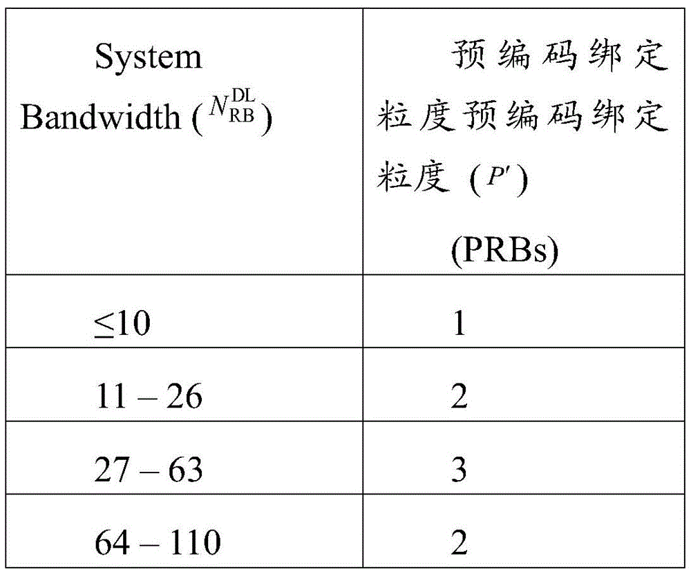
in the existing LTE system, when there is PMI feedback, the feedback granularity cannot be too small due to overhead reasons, the precoding granularity is greater than one PRB and is based on a Physical Resource Block Group (PRBG) level, and the number of PRBs included in one PRBG is shown in table 1. Has a relationship with the system bandwidth. If there is no PMI feedback, it is likely to be a TDD system with better reciprocity, and can obtain more accurate RB-level channel information, so that RB-level precoding is adopted, and the granularity of precoding is one RB.
TABLE 1
The problems of the prior art are as follows: the pre-coding granularity configuration is some well-agreed values and is not very flexible; the pre-coding granularity is only determined according to the bandwidth and cannot be well adapted to various transmission conditions; the granularity of precoding does not support dynamic change in the time domain;
much like the precoding bundling parameter, the same problem exists for the resource aggregation parameter. Here, resource aggregation is mainly a resource allocation size for uplink or downlink.
Channel to resource mapping parameters: in the conventional technology, a simple method of sequentially mapping a signal to a resource in a space domain, a frequency domain and a time domain is adopted. This technique has two major technical drawbacks in 5G NR;
the first problem is: since the amount of data transmitted in NR is many times that of the existing 4G system, the LDPC coded TB block is large and each CB supports only a maximum of 8192 bits, and thus is divided into a plurality of CBs, which are independently coded. As the acquisition of diversity gain requires that information in the same CB undergoes multiple different transmissions, if the bandwidth is large, tens of CBs may be supported, and sequential mapping in the prior art may cause that one CB is only mapped to some subcarriers of a certain symbol, which may not sufficiently acquire diversity gain and affect performance;
the second problem is: since the URLLC service that NR needs to support has very low transmission delay requirement, the waiting time in the queue must also be short, and for downlink service, when the URLLC service arrives at the base station, the URLLC service needs to be scheduled out quickly. Similarly, for uplink traffic, it needs to be quickly transmitted from the terminal. The eMMC service and the URLLC service are subjected to frequency division multiplexing, and the reservation of sufficient resources for the URLLC service is a mode, but the URLLC service is low in sending frequency, and a large amount of frequency resources need to be reserved under the condition of short scheduling interval due to high reliability requirement, so that the resource reservation method brings great resource waste, and the method is not a good solution for NR network supporting the URLLC service. When the base station is transmitting the eMBB downlink traffic, another efficient way to support the URLLC traffic and the eMBB traffic multiplexing is to allow the URLLC traffic to puncture the transmitted eMBB traffic, as shown in fig. 1. Because the eBB service is punctured by the URLLC service, the eBB terminal directly decodes all received data under the condition that the eBB terminal does not know which parts of the received data are covered by the URLLC data, and the performance is rapidly reduced. If the data dropped by the URRLC is the same CB, the CB cannot be paired, and needs to be retransmitted, which affects performance.
An effective solution has not been proposed yet to the problem of poor flexibility of the configuration related to transmission in the related art.
Disclosure of Invention
Embodiments of the present invention provide a transmission and transmission configuration method, apparatus, base station, and terminal, so as to at least solve the problem of poor flexibility of transmission-related configuration in the related art.
According to an embodiment of the present invention, there is provided a transmission method including: a sending end determines a transmission parameter set corresponding to a transmission resource area, wherein transmission parameters in the transmission parameter set include at least one of the following: a resource aggregation granularity parameter, a pre-coding granularity parameter, and a resource mapping parameter; and the sending end transmits in the corresponding transmission resource region according to the transmission parameters.
Optionally, the method further comprises: the sending end determines a transmission resource area, wherein the transmission resource comprises at least one of the following: the method comprises the steps of time domain resources, frequency domain resources, antenna resources, beam resources and code resources, wherein the number of transmission resource regions is N, and N is more than or equal to 1.
Optionally, the method further comprises: and the sending end sends the transmitted configuration signaling to the receiving end.
Optionally, the resource aggregation granularity parameter/precoding bundling parameter is configured separately by one or more of the following ways: at least two Downlink Control Information (DCI) types, at least two DCI overhead sizes, at least two transmission technologies, at least two pilot port groups, at least two types of channels/signals, at least two coding blocks/coding block groups (CB/CBG), at least two Transmission Blocks (TB)/code word streams (CW), at least two service types, at least two waveforms, at least two beam types, at least two beam groups, at least two time domain symbol groups/time slot groups/subframe groups, at least two antennas, at least two modulation and policy coding (MCS), at least two resource mapping modes, at least two receiving modes and at least two hybrid automatic repeat request (HARQ) related parameters.
Optionally, the resource aggregation granularity parameter/precoding granularity parameter includes at least one time window parameter, where the time window parameter is used to determine the resource aggregation granularity parameter/precoding binding granularity.
Optionally, the allocation manner of the time window parameter includes: respectively allocating the time window parameters for at least two channels/signals; or, the time window parameters are respectively configured for at least two beam groups; or, the time window parameters are respectively configured for at least two transmission resource areas.
Optionally, the mapping configuration of the transmission parameters to the transmission resource region is determined by at least one of the following ways: at least two layers, at least two Layer numbers, at least two CWs, at least two MCSs, at least two reference demodulation pilot DMRS configurations, at least two phase noise pilot PTRS configurations, at least two Numerology configurations, at least two Waveforms, at least two Slot types, at least two Transmission schemes, at least two DCI types, at least two Transmission types, at least two CB/CBG configurations, at least two Transmission setting configurations, at least two beams, at least two beam numbers, at least two reception modes, at least two precoding bundling granularity/resource aggregation granularity, at least two HARQ related parameters, at least two multiple access modes/multiplexing modes.
Optionally, the configuration manner of the precoding bundling granularity includes: and dynamically configuring the pre-coding binding granularity through DCI signaling.
According to another embodiment of the present invention, there is provided a transmission configuration method including: a receiving end determines a transmission resource region, wherein the transmission resource comprises: time domain resources, frequency domain resources, antenna resources, beam resources, code resources; the receiving end determines a transmission parameter set corresponding to the transmission resource region, wherein transmission parameters in the transmission parameter set include at least one of the following: resource aggregation granularity parameters, pre-coding granularity parameters, mapping parameters and coding blocks/coding block groups CB/CBG.
Optionally, the method further comprises: and the receiving end transmits in the transmission resource region according to the transmission parameter set.
Optionally, the resource aggregation granularity parameter/precoding bundling parameter is determined according to one or more of the following information: downlink control information DCI type, transmission technology, pilot frequency port group, channel/signal type, CB/CBG configuration, service type, waveform, beam type, beam group, time domain symbol group/time slot group/subframe group, antenna group, modulation and strategy coding MCS group, resource allocation granularity, pilot frequency pattern, antenna/port number, hybrid automatic repeat request HARQ related parameter, receiving mode, multiple access mode, multiplexing mode, and configuration of quasi co-location QCL.
Optionally, the receiving end determines a pre-coding granularity parameter of a second channel/signal according to the pre-coding granularity parameter of the first channel/signal; the receiving end determines the pre-coding granularity parameter of the uplink data/reference demodulation pilot frequency DMRS according to the following information: detecting a precoding granularity parameter of a reference signal SRS and a precoding granularity parameter of uplink control; the receiving end determines the precoding granularity parameter of the uplink control/DMRS according to the following information: detecting a pre-coding granularity parameter of a reference signal SRS and a pre-coding granularity parameter of uplink data; and the receiving end determines the precoding granularity parameter of downlink data/downlink control/DMRS according to the precoding granularity parameter of the channel state information measurement pilot frequency CSI-RS.
Optionally, the receiving end determines a pre-coding granularity parameter of an uplink channel/signal according to the pre-coding granularity parameter of the downlink channel/signal; the receiving end determines the pre-coding granularity parameter of the SRS according to the pre-coding granularity parameter of the CSI-RS; the receiving end determines the pre-coding granularity parameter of the UL DMRS according to the pre-coding granularity parameter of the CSI-RS
Optionally, the receiving end determines a pre-coding granularity parameter of the downlink channel/signal according to the pre-coding granularity parameter of the uplink channel/signal.
Optionally, there is a multiple relationship between the binding granularities of at least two channels/signals, and there is a multiple relationship between the precoding binding granularities of at least two pilot ports.
Optionally, the resource aggregation granularity parameter/precoding granularity parameter includes at least one time window parameter, where the time window parameter is used to determine the resource aggregation granularity parameter/precoding binding granularity.
Optionally, the determining manner of the time window parameter includes: determining the time window parameter according to the type of the transmission channel/signal; or, determining the time window parameter according to the beam group to which the transmission belongs; or, the time window parameter is determined according to the transmission resource region.
Optionally, the mapping configuration of the information to the resource is respectively determined by: layer/Layer group, layer number, MCS, DMRS pattern, PTRS pattern, numerology, waveform, slot type, transmission scheme, DCI type, traffic type, CB/CBG configuration, transmission setting configuration, beam number, receiving mode, precoding binding granularity/resource aggregation granularity, HARQ related parameters, multiple access mode, multiplexing mode, A/N configuration, CW/TB configuration, QCL configuration.
Optionally, the candidate set of mapping configurations of information to resources includes at least one discrete CB/CBG mapping and a centralized CB/CBG mapping.
According to another embodiment of the present invention, there is provided a transmission apparatus including: applied to a transmitting end, comprising: a first determining module, configured to determine a transmission parameter set corresponding to a transmission resource region, where a transmission parameter in the transmission parameter set includes at least one of: a resource aggregation granularity parameter, a pre-coding granularity parameter, and a resource mapping parameter; and the transmission module is used for transmitting in the corresponding transmission resource region according to the transmission parameters.
Optionally, the apparatus further comprises: means for determining a transmission resource region, wherein the transmission resource comprises at least one of: the method comprises the steps of time domain resources, frequency domain resources, antenna resources, beam resources and code resources, wherein the number of transmission resource regions is N, and N is more than or equal to 1.
Optionally, the apparatus further comprises: and sending the transmitted configuration signaling to a module at the receiving end.
Optionally, the resource aggregation granularity parameter/precoding bundling parameter is configured separately by one or more of the following ways: at least two Downlink Control Information (DCI) types, at least two DCI overhead sizes, at least two transmission technologies, at least two pilot port groups, at least two types of channels/signals, at least two coding blocks/coding block groups (CB/CBG), at least two Transmission Blocks (TB)/code word streams (CW), at least two service types, at least two waveforms, at least two beam types, at least two beam groups, at least two time domain symbol groups/time slot groups/subframe groups, at least two antennas, at least two modulation and policy coding (MCS), at least two resource mapping modes, at least two receiving modes and at least two hybrid automatic repeat request (HARQ) related parameters.
Optionally, the resource aggregation granularity parameter/precoding granularity parameter includes at least one time window parameter, where the time window parameter is used to determine the resource aggregation granularity parameter/precoding binding granularity.
Optionally, the allocation manner of the time window parameter includes: respectively allocating the time window parameters for at least two channels/signals; or, the time window parameters are respectively configured for at least two beam groups; or, the time window parameter is configured for at least two transmission resource regions respectively.
Optionally, the mapping configuration of the information to the resource is determined by at least one of the following methods: at least two layers, at least two Layer numbers, at least two CWs, at least two MCSs, at least two reference demodulation pilot DMRS configurations, at least two phase noise pilot PTRS configurations, at least two Numerology configurations, at least two Waveforms, at least two Slot types, at least two Transmission schemes, at least two DCI types, at least two Transmission types, at least two CB/CBG configurations, at least two Transmission setting configurations, at least two beams, at least two beam numbers, at least two reception modes, at least two precoding bundling granularity/resource aggregation granularity, at least two HARQ related parameters, at least two multiple access modes/multiplexing modes.
Optionally, the transmission parameters further include configuration information of the CB or CBG, and the terminal may determine the configuration of the CB and CBG according to the following information: the capability of the receiving node, the configuration of the number of layers, the DCI type of the downlink control information, the transmission technology, the configuration of demodulation pilot frequency, the granularity of resource allocation, the configuration of a multiple access mode, a multiplexing mode, MCS configuration, a multiplexing mode and quasi co-location QCL.
According to another embodiment of the present invention, there is provided a transmission apparatus including: applied to a receiving end, comprising: a second determining module, configured to determine a transmission resource region, where the transmission resource includes: time domain resources, frequency domain resources, antenna resources, beam resources, code resources; a third determining module, configured to determine a transmission parameter set corresponding to the transmission resource region, where a transmission parameter in the transmission parameter set includes at least one of: resource aggregation granularity parameters, pre-coding granularity parameters, mapping parameters and coding blocks/coding block groups CB/CBG.
Optionally, the apparatus further comprises: and the module transmits in the transmission resource region according to the transmission parameter set.
Optionally, the resource aggregation granularity parameter/precoding bundling parameter is determined according to one or more of the following information: downlink control information DCI type, transmission technology, pilot frequency port group, channel/signal type, CB/CBG configuration, service type, waveform, beam type, beam group, time domain symbol group/time slot group/subframe group, antenna group, modulation and strategy coding MCS group, resource allocation granularity, pilot frequency pattern, antenna/port number, hybrid automatic repeat request HARQ related parameter, receiving mode, multiple access mode, multiplexing mode, and configuration of quasi co-location QCL.
Optionally, the apparatus determines a precoding granularity parameter of a second channel/signal according to the precoding granularity parameter of the first channel/signal; the device determines a precoding granularity parameter of an uplink data/reference demodulation pilot frequency DMRS according to the following information: detecting a precoding granularity parameter of a reference signal SRS and a precoding granularity parameter of uplink control; the device determines the precoding granularity parameter of the uplink control/DMRS according to the following information: detecting a pre-coding granularity parameter of a reference signal SRS and a pre-coding granularity parameter of uplink data; the device determines the precoding granularity parameter of downlink data/downlink control/DMRS according to the precoding granularity parameter of the channel state information measurement pilot frequency CSI-RS.
Optionally, the apparatus determines a pre-coding granularity parameter of an uplink channel/signal according to a downlink channel/signal pre-coding granularity parameter; the device determines a precoding granularity parameter of the SRS according to the precoding granularity parameter of the CSI-RS; the device determines the precoding granularity parameter of the UL DMRS according to the precoding granularity parameter of the CSI-RS
Optionally, the apparatus determines a precoding granularity parameter of the downlink channel/signal according to the precoding granularity parameter of the uplink channel/signal.
Optionally, there is a multiple relationship between the binding granularities of at least two channels/signals, and there is a multiple relationship between the precoding binding granularities of at least two pilot ports.
Optionally, the resource aggregation granularity parameter/precoding granularity parameter includes at least one time window parameter, where the time window parameter is used to determine the resource aggregation granularity parameter/precoding binding granularity.
Optionally, the determining manner of the time window parameter includes: determining the time window parameter according to the type of the transmission channel/signal; or, determining the time window parameter according to the beam group to which the transmission belongs; or, determining the time window parameter according to the transmission resource region.
Optionally, the mapping configuration of the information to the resource is respectively determined by: layer/Layer group, layer number, MCS, DMRS pattern, PTRS pattern, numerology, waveform, slot type, transmission scheme, DCI type, traffic type, CB/CBG configuration, transmission setting configuration, beam number, receiving mode, precoding binding granularity/resource aggregation granularity, HARQ related parameters, multiple access mode, multiplexing mode, A/N configuration, CW/TB configuration, QCL configuration.
Optionally, the candidate set of mapping configurations of the transmission resource region at least includes a discrete CB/CBG mapping and a centralized CB/CBG mapping.
According to still another embodiment of the present invention, there is also provided a base station including: a processor and a memory storing processor-executable instructions that, when executed by the processor, perform operations comprising: determining a transmission parameter set corresponding to a transmission resource region, wherein transmission parameters in the transmission parameter set include at least one of: a resource aggregation granularity parameter, a pre-coding granularity parameter, and a resource mapping parameter; and transmitting in the corresponding transmission resource region according to the transmission parameters.
Optionally, the resource aggregation granularity parameter/precoding bundling parameter is configured separately by one or more of the following ways: at least two Downlink Control Information (DCI) types, at least two DCI overhead sizes, at least two transmission technologies, at least two pilot port groups, at least two types of channels/signals, at least two coding blocks/coding block groups (CB/CBG), at least two Transmission Blocks (TB)/code word streams (CW), at least two service types, at least two waveforms, at least two beam types, at least two beam groups, at least two time domain symbol groups/time slot groups/subframe groups, at least two antennas, at least two modulation and policy coding (MCS), at least two resource mapping modes, at least two receiving modes and at least two hybrid automatic repeat request (HARQ) related parameters.
According to still another embodiment of the present invention, there is also provided a terminal including: a processor and a memory storing processor-executable instructions that, when executed by the processor, perform the following: determining a transmission resource region, wherein the transmission resource comprises: time domain resources, frequency domain resources, antenna resources, beam resources, code resources;
determining a transmission parameter set corresponding to the transmission resource region, wherein transmission parameters in the transmission parameter set include at least one of: resource aggregation granularity parameters, pre-coding granularity parameters, mapping parameters and coding blocks/coding block groups CB/CBG.
Optionally, the resource aggregation granularity parameter/precoding bundling parameter is determined according to one or more of the following information: downlink control information DCI type, transmission technology, pilot frequency port group, channel/signal type, CB/CBG configuration, service type, waveform, beam type, beam group, time domain symbol group/time slot group/subframe group, antenna group, modulation and strategy coding MCS group, resource allocation granularity, pilot frequency pattern, antenna/port number, hybrid automatic repeat request HARQ related parameter, receiving mode, multiple access mode, multiplexing mode and quasi-co-location QCL configuration.
According to still another embodiment of the present invention, there is also provided a storage medium. The storage medium is configured to store program code for performing the steps of:
a sending end determines a transmission parameter set corresponding to a transmission resource area, wherein transmission parameters in the transmission parameter set include at least one of the following: a resource aggregation granularity parameter, a pre-coding granularity parameter, and a resource mapping parameter;
and the sending end transmits in the corresponding transmission resource region according to the transmission parameters.
Optionally, the storage medium is further arranged to store program code for performing the steps of:
a receiving end determines a transmission resource area, wherein the transmission resource comprises: time domain resources, frequency domain resources, antenna resources, beam resources, code resources;
the receiving end determines a transmission parameter set corresponding to the transmission resource region, wherein transmission parameters in the transmission parameter set include at least one of the following: resource aggregation granularity parameter, pre-coding granularity parameter, mapping parameter, coding block/coding block group CB/CBG.
Through the invention, the sending end determines the transmission parameter set corresponding to the transmission resource area, wherein the transmission parameters in the transmission parameter set comprise at least one of the following parameters: a resource aggregation granularity parameter, a pre-coding granularity parameter, and a resource mapping parameter; the sending end transmits in the corresponding transmission resource region according to the transmission parameters, so that the sending end can more flexibly configure the transmission parameters, and the problem of poor flexibility of transmission-related configuration in the related technology is solved.
Drawings
The accompanying drawings, which are included to provide a further understanding of the invention and are incorporated in and constitute a part of this application, illustrate embodiment(s) of the invention and together with the description serve to explain the invention without limiting the invention. In the drawings:
fig. 1 is a diagram illustrating a transmission method in the related art;
FIG. 2 is a flow chart of a transmission method according to an embodiment of the present invention;
FIG. 3 is a schematic diagram of a transmission method according to an embodiment of the invention;
FIG. 4 is a first diagram illustrating a transmission method according to an embodiment of the present invention;
FIG. 5 is a second diagram of a transmission method according to an embodiment of the invention;
fig. 6 is a block diagram of a transmission apparatus according to an embodiment of the present invention;
fig. 7 is a flow chart of a transmission configuration method according to an embodiment of the present invention;
fig. 8 is a schematic diagram of a transmission configuration method according to an embodiment of the present invention;
fig. 9 is a first schematic diagram of a transmission configuration method according to an embodiment of the present invention;
fig. 10 is a block diagram of a configuration of a transmission configuration apparatus according to an embodiment of the present invention.
Detailed Description
The invention will be described in detail hereinafter with reference to the accompanying drawings in conjunction with embodiments. It should be noted that the embodiments and features of the embodiments in the present application may be combined with each other without conflict.
It should be noted that the terms "first," "second," and the like in the description and claims of the present invention and in the drawings described above are used for distinguishing between similar elements and not necessarily for describing a particular sequential or chronological order.
Example 1
In this embodiment, a transmission method is provided, and fig. 2 is a flowchart of a transmission method according to an embodiment of the present invention, as shown in fig. 2, the flowchart includes the following steps:
step S202, the sending end determines a transmission parameter set corresponding to the transmission resource region, where the transmission parameters in the transmission parameter set include at least one of the following: a resource aggregation granularity parameter, a pre-coding granularity parameter, and a resource mapping parameter;
step S204, the sending end transmits in the corresponding transmission resource area according to the transmission parameter.
Optionally, in this embodiment, the sending end includes, but is not limited to: and a base station.
Through the above steps, the sending end determines a transmission parameter set corresponding to the transmission resource area, wherein the transmission parameters in the transmission parameter set include at least one of the following: a resource aggregation granularity parameter, a pre-coding granularity parameter, and a resource mapping parameter; the sending end transmits in the corresponding transmission resource region according to the transmission parameters, so that the sending end can more flexibly configure the transmission parameters, and the problem of poor flexibility of transmission-related configuration in the related technology is solved.
In an optional embodiment, the foregoing further includes: the sending end determines a transmission resource region, wherein the transmission resource comprises at least one of the following: the system comprises time domain resources, frequency domain resources, antenna resources, beam resources and code resources, wherein the number of transmission resource regions is N, and N is more than or equal to 1.
Optionally, the sending end sends the transmitted configuration signaling to the receiving end.
In this embodiment, the resource aggregation granularity parameter/precoding bundling parameter may be configured by one or more of the following manners:
at least two Downlink Control Information (DCI) types, at least two DCI overhead sizes, at least two transmission technologies, at least two pilot port groups, at least two types of channels/signals, at least two coding blocks/coding block groups (CB/CBG), at least two Transmission Blocks (TB)/code word streams (CW), at least two service types, at least two waveforms, at least two beam types, at least two beam groups, at least two time domain symbol groups/time slot groups/subframe groups, at least two antennas, at least two modulation and policy coding (MCS), at least two resource mapping modes, at least two receiving modes and at least two hybrid automatic repeat request (HARQ) related parameters.
The resource aggregation granularity parameter/precoding granularity parameter includes at least one time window parameter, where the time window parameter is used to determine the resource aggregation granularity parameter/precoding binding granularity. The allocation mode of the time window parameters comprises the following steps: respectively allocating the time window parameters for at least two channels/signals; or, the time window parameters are respectively configured for at least two beam groups; or, the time window parameter is configured for at least two transmission resource regions respectively.
Alternatively, the mapping configuration of the information to the resource may be determined by at least one of the following manners: at least two layers, at least two Layer numbers, at least two CWs, at least two MCSs, at least two reference demodulation pilot DMRS configurations, at least two phase noise pilot PTRS configurations, at least two Numerology configurations, at least two Waveforms, at least two Slot types, at least two Transmission schemes, at least two DCI types, at least two Transmission types, at least two CB/CBG configurations, at least two Transmission setting configurations, at least two beams, at least two beam numbers, at least two reception modes, at least two precoding bundling granularity/resource aggregation granularity, at least two HARQ related parameters, at least two multiple access modes/multiplexing modes.
The present embodiment will be described below with reference to specific examples.
Alternative embodiment 1
The base station configures resource aggregation granularity parameter/precoding binding parameter for at least two DCI types, as shown in table 2:
TABLE 2

The resource aggregation granularity parameter/precoding binding parameter is configured for at least two DCI overhead sizes, as shown in table 3:
TABLE 3

The resource aggregation granularity parameter/precoding binding parameter configured for at least two transmission technologies respectively is shown in table 4:
TABLE 4

The resource aggregation granularity parameter/precoding binding parameter configured for at least two pilot port groups respectively is shown in table 5;
TABLE 5

Resource aggregation granularity parameters/precoding binding parameters are respectively configured for at least two types of channels/signals, as shown in table 6:
TABLE 6

Respectively configuring a resource aggregation granularity parameter/a precoding binding parameter aiming at least two CB/CBGs;
the CB identifies a plurality of independent coding blocks in the transport block and the CBG identifies a group of coding blocks as shown in table 7.
TABLE 7

Table 8 may show:
TABLE 8


That is, if the configuration of the current TB split into CBs/CBGs changes, the aggregation granularity parameter/precoding bundling parameter thereof may be different.
Respectively configuring resource aggregation granularity parameters/precoding binding parameters for at least two TBs/CWs; TB denotes a transport block, CW identifies a codeword stream codeword, which is generally considered as a concept, as shown in table 9.
TABLE 9

Respectively configuring resource aggregation granularity parameters/precoding binding parameters aiming at least two service types; as shown in table 10.
Watch 10

The resource aggregation granularity parameter/precoding bundling parameter configured separately for at least two types of waveforms is shown in table 11.
TABLE 11


Respectively configuring a resource aggregation granularity parameter/a precoding binding parameter aiming at least two wave beam types; as shown in table 12.
TABLE 12

The resource aggregation granularity parameter/precoding bundling parameter configured for at least two beam groups respectively is shown in table 13.
Watch 13

Configuring resource aggregation granularity parameters/precoding binding parameters for at least two time domain symbol groups/time slot groups/subframe groups respectively, as shown in table 14;
as shown in Table 14


Respectively configuring a resource aggregation granularity parameter/a precoding binding parameter for at least two antennas; as shown in Table 15;
watch 15

Respectively configuring resource aggregation granularity parameters/precoding binding parameters aiming at least two MCS; as shown in Table 16;
TABLE 16

Respectively configuring a resource aggregation granularity parameter/a pre-coding binding parameter aiming at least two resource mapping modes; as shown in table 17;
TABLE 17


Respectively determining a resource aggregation granularity parameter/a precoding binding parameter aiming at least two receiving modes; as shown in Table 18;
watch 18

For at least the HARQ related parameter; (e.g., new/old data status, redundancy version number;) determining resource aggregation granularity parameter/precoding binding parameter, respectively; as shown in tables 19 to 21;
watch 19

Watch 20

TABLE 21


Alternative embodiment 2:
the resource aggregation granularity parameter/precoding granularity parameter includes at least one time window parameter, as shown in fig. 3, where the time window is used to determine the resource aggregation granularity parameter/precoding binding granularity;
the time window may be determined in several ways: determination of the starting time:
mode 1: specifying a start time location at configuration
Mode 2: taking the event occurrence time as the starting time according to the convention
Mode 3: shifting by one value according to the appointed event occurrence time as the starting time
The above event may preferably be defined as the receipt of configuration signaling;
or the first transmission after receiving the configuration signaling;
determination of the end time:
mode 1: configuring end time locations of signaling
Mode 2: taking the event occurrence time as the ending time according to the convention
Mode 3: shifting by one more value as ending time according to appointed event occurrence time
The above event may be preferably defined as the reception of an end indication signaling;
the above event may preferably be defined as the receipt of reconfiguration signalling;
one such situation is shown in figure 4:
the transmission parameter configuration 1 is a default configuration, and when the transmission parameter configuration 2 is configured, the transmission parameter configuration 2 is effective in the action time. When the transmission parameter configuration 3 is configured, the transmission configuration 3 is valid during its action time. And the transmission parameter configuration 1 is effective in other time. There are also cases where transmission parameter configuration 1 is used in combination with transmission parameter configuration 2 to determine the final configuration when transmission parameter configuration 2 is configured. When the transmission parameter configuration 3 is configured, the transmission parameter configuration 1 is used in combination with the transmission parameter configuration 3 to determine the final configuration.
The sending end configures the time window parameter for different channels/signals respectively.
The sending end respectively configures the time window parameters for a plurality of different beam groups;
the sending end respectively configures the time window parameter for a plurality of different frequency domain transmission resource regions;
alternative embodiment 3:
the sending end can respectively determine the mapping configuration of the information to the resources aiming at least two layers; for example, layer1 transmission and layer2 transmission configure mapping mode respectively
The sending end can respectively determine the mapping configuration of the information to the resources aiming at least two Layer numbers; for example, mapping modes are configured for 2layer transmission and 4layer transmission respectively
The transmitting end can respectively determine the mapping configuration of the information to the resources aiming at least two CWs; for example, mapping modes are configured for CW1 transmission and CW2 transmission respectively
The sending end can respectively determine the mapping configuration from the information to the resources aiming at least two MCS; for example, MCS1 transmission and MCS2 transmission configure mapping method respectively
A transmitting end can respectively determine information-to-resource mapping configuration aiming at least two DMRS configurations; for example, mapping manners are respectively configured for data transmission or control information transmission corresponding to DMRS pattern1 and DMRS pattern 2. And respectively configuring a mapping mode for data transmission or control information transmission corresponding to the DMRS port number 2 and the DMRS port number 4. And respectively configuring a mapping mode for data transmission or control information transmission corresponding to DMRS OCC =2, DMRS OCC = 4.
The sending end can respectively determine information-to-resource mapping configuration aiming at least two PTRS configurations; the configuration here includes parameters of location, density, port number, enable status, and the like.
The transmitting end may determine information-to-resource mapping configurations for at least two Numerology configurations, respectively; the numerology parameters here include: CP length, subcarrier density, subcarrier spacing, symbol length, number of FFT points
The sending end can respectively determine the mapping configuration from the information to the resources aiming at least two types of waveforms; such as CP-OFDM, SC-FDMA, can determine the resource mapping configuration, respectively.
The transmitting end can respectively determine the mapping configuration from the information to the resources aiming at least two Slot types;
the sending end can respectively determine the mapping configuration from the information to the resource aiming at least two Transmission schemes;
the sending end can respectively determine the mapping configuration of the information to the resources aiming at least two DCI types;
the sending end can respectively determine the mapping configuration from the information to the resources aiming at least two Traffic types;
the sending end can respectively determine information-to-resource mapping configuration aiming at least two CB/CBG configurations;
the sending end can respectively determine the mapping configuration from the information to the resource aiming at least two Transmission setting configurations;
the sending end can respectively determine the mapping configuration from the information to the resources aiming at least two beams;
the sending end can respectively determine the mapping configuration of the information to the resources aiming at least two beam numbers;
the sending end can respectively determine the mapping configuration of the information to the resources aiming at least two receiving modes;
the sending end can respectively determine the mapping configuration of the information to the resource aiming at least two pre-coding binding granularities/resource aggregation granularities;
the transmitting end may be directed to at least HARQ related parameters; (e.g. process number, new/old data status, redundancy version number) determining resource aggregation granularity parameter/precoding binding parameter respectively;
the transmitting end can respectively determine the mapping configuration of the information to the resources aiming at least two multiple access modes/multiplexing modes.
Alternative embodiment 4
In 5G, since the supported working frequency range spans a lot, the application scenarios are also many, and therefore the channel characteristics may be more differentiated than in 4G. In addition, for a multi-beam system, different rf beam width configurations may occur, and corresponding channel frequency selection sizes are also different. Determining the precoding bundling granularity based solely on bandwidth size and whether there is PMI feedback does not appear to be a suitable approach. Enhancements in configuration flexibility need to be considered. The potential enhancement needs may come from some of the following:
a. for closed-loop transmission of a control channel and a data channel, the used transmit and receive beams are not necessarily the same, the control channel may use a wider beam for transmission and reception, and the data channel may use a narrower beam, and since the effective number of multipaths within the wide beam and the narrow beam are different, the corresponding frequency selection may be different. More flexible precoding binding granularity configuration may have better performance.
b. The transmit or receive beams used by the downlink data or control channels may change over time. On the one hand, the width of the beam may vary. With beam training, the beam may become narrower and narrower. On the other hand, even if the beam widths are the same, the beams from different directions are affected differently by the multipath delay and the TAE, and the base station may pre-configure different precoding bundling granularities for different transmit/receive beams or BPLs (transmit/receive beam pairs)
c. When downlink data is transmitted using multiple beams and corresponds to different layers, the frequency selection of a channel corresponding to each transmission layer may be different. The two layers may be configured with different PRB sizes, respectively.
d. For open-loop transmission or semi-open-loop transmission, the base station configures precoding bundling granularity with different sizes, which means different diversity gains. In the case of relatively more allocated frequency domain resources, a larger precoding bundling granularity may be used, but in the case of relatively smaller frequency domain resource allocation, a relatively smaller precoding bundling granularity should be configured in order to obtain sufficient diversity gain. There may be differences in the granularity of the most appropriate precoding bindings for different resource allocations.
e. For coordinated multipoint transmission, if the sending node is dynamically switched, the corresponding channel characteristics will often change significantly. The configuration of the quasi-co-location relationship indicates that the precoding bundling granularity may vary. In addition, there is also a significant frequency-selective difference between dynamic node switching DPS and joint transmission JT. JT transmission is equivalent to adding a large number of multipaths, and the delays of multipaths from different transmission nodes TP may also be significantly different, so the frequency selection may be much larger.
for low SNR, generally, a larger precoding bundling granularity needs to be configured to ensure the estimation performance of DMRS, while for high SNR, it is more important to improve the precoding transmission efficiency, and at this time, a smaller precoding bundling granularity may be configured.
Alternative embodiment 5
There are two ways to achieve flexible precoding binding granularity configuration:
mode 1: the base station may configure the precoding bundling granularity separately for multiple transmission hypotheses, for example: allocating and configuring corresponding pre-coding binding granularity for a plurality of sending beam/receiving beam/BPL, respectively allocating corresponding pre-coding binding granularity for a plurality of transmission technologies, respectively allocating corresponding pre-coding binding granularity for a plurality of band resource allocation conditions, and the like. And the terminal determines the corresponding precoding binding granularity according to the current transmission. In the presence of Beam corerespondence, the precoding binding granularity of the uplink and downlink channels or the channels can be configured jointly, and the precoding binding granularity of the channels or the channels with the binding relationship is the same.
Mode 2: the precoding binding granularity is dynamically configured through signaling of the DCI to adapt to dynamic changes of receiving and transmitting beams, allocated resources, MCS and the like.
One configuration method is shown in fig. 5: the base station configures a precoding binding granularity value set through RRC, and the MAC CE selects a subset from the set and activates the subset for a period of time. DCI selects a precoding bundling granularity value from the subset.
If only the configuration of RRC signaling and DCI signaling is available, and there is no case of size subset selection indicated by a valid MAC CE, a default subset selection mode needs to be agreed.
If there is only RRC signaling and valid configuration of MAC CE, but there is no DCI signaling, it is necessary to agree on a way to select a default value, such as the first value, from the size subset configured by MAC CE.
If only RRC signaling configuration exists, there is no valid MAC CE configuration and DCI indication, it is necessary to agree on a method of determining a default value from the RRC configured size set.
It is noted that besides configuring precoding binding granularity subset selection by MAC CE, implementation by DCI is also contemplated.
Alternative embodiment 6
The aforementioned precoding bindings may be for the sender or for the receiver.
The bundling time window of the transmit beam may be a subset of the receive beam precoding bundling window.
It should be further noted that, in the aforementioned transceiving beams, the transmitting beam can be characterized by a quasi-co-location relationship with other reference signals, and the receiving beam can be characterized by a correlation relationship with spatial features of other reference signals. A receive/transmit beam is a specific form of a receive/transmit scheme.
Alternative embodiment 7
The transmission parameter information may further include configuration information of the CB or the CBG, and the terminal may determine the configuration of the CB and the CBG according to the following information: the capability of the receiving node, the configuration of the number of layers, the DCI type, the transmission technology, the demodulation pilot frequency configuration, the resource allocation granularity, the configuration of the multi-access mode, the multiplexing mode, the MCS configuration, the multiplexing mode, the quasi co-location QCL and other information.
Through the above description of the embodiments, those skilled in the art can clearly understand that the apparatus according to the above embodiments can be implemented by software plus a necessary general hardware platform, and certainly can also be implemented by hardware, but the former is a better implementation mode in many cases. Based on such understanding, the technical solutions of the present invention may be embodied in the form of a software product, which is stored in a storage medium (such as ROM/RAM, magnetic disk, optical disk) and includes instructions for enabling a terminal device (such as a mobile phone, a computer, a server, or a network device) to execute the apparatus according to the embodiments of the present invention.
Example 2
In this embodiment, a transmission device is further provided, and the device is used to implement the foregoing embodiments and preferred embodiments, and the description of the device already made is omitted. As used below, the term "module" may be a combination of software and/or hardware that implements a predetermined function. Although the means described in the embodiments below are preferably implemented in software, an implementation in hardware or a combination of software and hardware is also possible and contemplated.
Fig. 6 is a block diagram of a transmission apparatus according to an embodiment of the present invention, as shown in fig. 6, the apparatus including:
1) A first determining module 62, configured to determine a transmission parameter set corresponding to a transmission resource region, where a transmission parameter in the transmission parameter set includes at least one of: a resource aggregation granularity parameter, a pre-coding granularity parameter, and a resource mapping parameter;
2) A transmission module 64, configured to perform transmission in the corresponding transmission resource region according to the transmission parameter.
By the device, the transmitting end can flexibly configure the transmission parameters, and the problem of poor flexibility of transmission-related configuration in the related technology is solved.
In an optional embodiment, the resource aggregation granularity parameter/precoding bundling parameter is configured by one or more of the following ways:
at least two Downlink Control Information (DCI) types, at least two DCI overhead sizes, at least two transmission technologies, at least two pilot port groups, at least two types of channels/signals, at least two coding blocks/coding block groups (CB/CBG), at least two Transmission Blocks (TB)/code word streams (CW), at least two service types, at least two waveforms, at least two beam types, at least two beam groups, at least two time domain symbol groups/time slot groups/subframe groups, at least two antennas, at least two modulation and policy coding (MCS), at least two resource mapping modes, at least two receiving modes and at least two hybrid automatic repeat request (HARQ) related parameters.
Example 3
In this embodiment, a transmission configuration method is provided, and fig. 7 is a flowchart of a transmission configuration method according to an embodiment of the present invention, as shown in fig. 7, the flowchart includes the following steps:
step S702, the receiving end determines a transmission resource region, wherein the transmission resource includes: time domain resources, frequency domain resources, antenna resources, beam resources, code resources;
step S704, the receiving end determines a transmission parameter set corresponding to the transmission resource region, wherein the transmission parameters in the transmission parameter set include at least one of the following: resource aggregation granularity parameters, pre-coding granularity parameters, mapping parameters and coding blocks/coding block groups CB/CBG.
Through the above steps, the receiving end determines a transmission resource region, wherein the transmission resource includes: time domain resources, frequency domain resources, antenna resources, beam resources, code resources; the receiving end determines a transmission parameter set corresponding to the transmission resource region, wherein the transmission parameters in the transmission parameter set include at least one of the following: the resource aggregation granularity parameter and the pre-coding granularity parameter enable a receiving end to be capable of configuring transmission parameters more flexibly, and the problem that configuration related to transmission in the related technology is poor in flexibility is solved.
Through the above steps, the sending end determines a transmission parameter set corresponding to the transmission resource area, wherein the transmission parameters in the transmission parameter set include at least one of the following: a resource aggregation granularity parameter, a pre-coding granularity parameter, and a resource mapping parameter; the sending end transmits in the corresponding transmission resource region according to the transmission parameters, so that the sending end can more flexibly configure the transmission parameters, and the problem of poor flexibility of transmission-related configuration in the related technology is solved.
In an optional implementation manner, the receiving end transmits within the transmission resource region according to the transmission parameter set.
Optionally, the resource aggregation granularity parameter/precoding bundling parameter is determined according to one or more of the following information: downlink control information DCI type, transmission technology, pilot frequency port group, channel/signal type, CB/CBG configuration, service type, waveform, beam type, beam group, time domain symbol group/time slot group/subframe group, antenna group, modulation and strategy coding MCS group, resource allocation granularity, pilot frequency pattern, antenna/port number, hybrid automatic repeat request HARQ related parameter, receiving mode, multiple access mode, multiplexing mode and quasi-co-location QCL configuration.
The receiving end determines the pre-coding granularity parameter of a second channel/signal according to the pre-coding granularity parameter of the first channel/signal; the receiving end determines the pre-coding granularity parameter of the uplink data/reference demodulation pilot frequency DMRS according to the following information: detecting a precoding granularity parameter of a reference signal SRS and a precoding granularity parameter of uplink control; the receiving end determines the precoding granularity parameter of the uplink control/DMRS according to the following information: detecting a pre-coding granularity parameter of a reference signal SRS and a pre-coding granularity parameter of uplink data; and the receiving terminal determines the precoding granularity parameter of the downlink data/downlink control/DMRS according to the precoding granularity parameter of the channel state information measurement pilot frequency CSI-RS.
Optionally, the receiving end determines a pre-coding granularity parameter of the uplink channel/signal according to the pre-coding granularity parameter of the downlink channel/signal; the receiving end determines the pre-coding granularity parameter of the SRS according to the pre-coding granularity parameter of the CSI-RS; the receiving terminal determines the pre-coding granularity parameter of the UL DMRS according to the pre-coding granularity parameter of the CSI-RS
And the receiving end determines the pre-coding granularity parameter of the downlink channel/signal according to the pre-coding granularity parameter of the uplink channel/signal.
Optionally, in this embodiment, there is a multiple relationship between the binding granularities of at least two channels/signals, and there is a multiple relationship between the precoding binding granularities of at least two pilot ports.
The resource aggregation granularity parameter/precoding granularity parameter includes at least one time window parameter, where the time window parameter is used to determine the resource aggregation granularity parameter/precoding binding granularity.
The determining mode of the time window parameter comprises the following steps: determining the time window parameter according to the type of the transmission channel/signal; or, determining the time window parameter according to the beam group to which the transmission belongs; alternatively, the time window parameter is determined based on the transmission resource region.
The mapping configuration of information to resources can be determined separately by: layer/Layer group, layer number, MCS, DMRS pattern, PTRS pattern, numerology, wavelet, slot type, transmission scheme, DCI type, transmission type, CB/CBG configuration, transmission setting configuration, beam, number of beams, receiving mode, precoding binding granularity/resource aggregation granularity, HARQ related parameters, multiple access mode, multiplexing mode, configuration of A/N, configuration of CW/TB, configuration of QCL.
The candidate set of mapping configuration of the transmission resource region at least comprises a discrete CB/CBG mapping and a centralized CB/CBG mapping.
The present embodiment will be described below with reference to specific examples.
Alternative embodiment 8
The receiving end determines the resource aggregation granularity parameter/pre-coding binding parameter according to one or more of the following information;
a DCI type; a transmission technique; a pilot port group; channel/signal type;
configuring CB/CBG; a service type; wave form; a beam type;
a beam group; time domain symbol group/slot group/subframe group; an antenna group;
an MCS group; a resource allocation granularity; a pilot pattern; number of antennas/ports;
HARQ related parameters; a receiving mode; a multiple access mode; a multiplexing mode; QCL configuration
One case is that the sending end configures different resource aggregation granularity parameters/precoding binding parameters for different types of information; at this time, the receiving end needs to determine the current resource aggregation granularity parameter/precoding binding parameter by combining the configuration signaling and the state of the type information and combining the configuration signaling.
In another case, the sending end and the receiving end agree on different values of the resource aggregation granularity parameter/precoding binding parameter for different states of the type information, and the current resource aggregation granularity parameter/precoding binding parameter can be determined according to the current state of the type information.
Alternative embodiment 9
The precoding bundling granularity between different channels/signals has a correlation, and the correlation preferably includes a functional relationship: specifically, the relationship may be a multiple relationship. The terminal determines a precoding granularity parameter of the second channel/signal according to the precoding granularity parameter of the first channel/signal;
for example: the terminal determines a precoding granularity parameter of uplink data/DMRS according to the precoding granularity parameter of the SRS;
the terminal determines a precoding granularity parameter of an uplink control/DMRS according to the precoding granularity parameter of the SRS;
the terminal determines a precoding granularity parameter of downlink data/DMRS according to the precoding granularity parameter of the CSI-RS;
the terminal determines a precoding granularity parameter of downlink control/DMRS according to the precoding granularity parameter of the CSI-RS;
the terminal determines a precoding granularity parameter of uplink data/DMRS according to the precoding granularity parameter of the uplink control;
the terminal determines a precoding granularity parameter of an uplink control/DMRS according to the precoding granularity parameter of the uplink data;
preferably, multiple relations exist among the binding granularities of various channels or signals;
preferably, the precoding binding granularity of a plurality of pilot ports has a multiple relation;
alternative embodiment 10
The precoding binding granularity between the uplink and downlink transmissions has relevance, and the relevance preferably includes a functional relationship. Specifically, the relationship may be a multiple relationship. The terminal determines a pre-coding granularity parameter of an uplink channel/signal according to the pre-coding granularity parameter of the downlink channel/signal;
the terminal determines a precoding granularity parameter of the SRS according to the precoding granularity parameter of the CSI-RS;
the terminal determines a precoding granularity parameter of the UL DMRS according to the precoding granularity parameter of the CSI-RS;
these types of uplink and downlink transmission channels/signals can be bundled together for parameter determination
Alternative embodiment 11
The resource aggregation granularity parameter/pre-coding granularity parameter comprises at least one time window parameter, and the time window is used for determining the resource aggregation granularity parameter/pre-coding binding granularity;
preferably, the receiving end determines the time window parameter according to the type of the transmitted channel/signal.
Preferably, the receiving end determines the time window parameter according to the beam group to which the transmission belongs;
preferably, the receiving end determines the time window parameter according to the transmission resource region;
optional embodiment 12 the receiving end determines the mapping configuration of information to resources for at least two receiving modes respectively;
a receiving end respectively determines information-to-resource mapping configuration aiming at least two pre-coding binding granularities/resource aggregation granularities;
the receiving end aims at least HARQ related parameters; (e.g. process number, new/old data status, redundancy version number) determining resource aggregation granularity parameter/precoding binding parameter respectively;
alternative embodiment 13
The receiving end determines the resource mapping configuration according to one or more of the following information;
respectively determining information to resource mapping configuration according to the Layer or the Layer group;
respectively determining information-to-resource mapping configuration according to the Layer number;
respectively determining information to resource mapping configuration according to the MCS;
respectively determining the mapping configuration of the information to the resources according to the DMRS pattern;
respectively determining information-to-resource mapping configuration according to the PTRS pattern;
respectively determining the mapping configuration of the information to the resources according to Numerology;
respectively determining the mapping configuration from the information to the resources according to the Waveform;
respectively determining information-to-resource mapping configuration according to the Slot type;
respectively determining information-to-resource mapping configuration according to Transmission scheme;
respectively determining information-to-resource mapping configuration according to the DCI type;
respectively determining information-to-resource mapping configuration according to Traffic type;
respectively determining information-to-resource mapping configuration according to CB/CBG configuration;
respectively determining information-to-resource mapping configuration according to Transmission setting configuration;
respectively determining the mapping configuration from the information to the resources according to the beam;
respectively determining the mapping configuration from the information to the resources according to the beam number;
respectively determining the mapping configuration from the information to the resources according to the receiving mode;
respectively determining information-to-resource mapping configuration according to the pre-coding binding granularity/the resource aggregation granularity;
determining information-to-resource mapping configuration according to the HARQ related parameters;
according to a multiple access method; determining the mapping configuration from the information to the resources by a multiplexing mode;
determining information-to-resource mapping configuration according to the configuration of the CW/TB;
determining information-to-resource mapping configuration according to the configuration of the QCL;
alternative embodiment 14
The main types of resource mapping configuration include discrete CB mapping and centralized CB mapping, as shown in fig. 8.
The above shaded lattices of the same type represent some transmission symbols corresponding to one CB interleaved and modulated, or some transmission symbols corresponding to one CBG fully interleaved and modulated
The resource mapping configuration at least comprises two modes of discrete CBG mapping and centralized CBG mapping
The discrete mode can be performed in time-frequency rather than frequency-domain discrete mode, as shown in fig. 9.
It should be noted that both centralized and distributed implementations actually involve a variety of specific mapping schemes. Generally, the centralized transmission diversity gain is small, but interference coordination is easily achieved. The distributed mode has large diversity gain, but interference coordination is not easy to carry out, and only interference randomization can be realized.
For the URLLC service, data on some symbols may be knocked out, in this case, if a/N is configured more, centralized mapping may be adopted, and large influence is avoided by retransmission of CBs or CBGs, and if a/N is configured less, distributed mapping may be adopted, and influence caused by knocking out REs is dispersed to different CBs, and error correction is performed by using coding redundancy.
In addition, the processing speeds of different mapping modes are different, the processing speed of a distributed mode is slower, especially in the time domain distributed mapping, and the centralized mapping is faster. The mapping manner can be determined according to the service type.
Through the above description of the embodiments, those skilled in the art can clearly understand that the apparatus according to the above embodiments can be implemented by software plus a necessary general hardware platform, and certainly can also be implemented by hardware, but the former is a better implementation mode in many cases. Based on such understanding, the technical solutions of the present invention or portions thereof contributing to the prior art may be embodied in the form of a software product, which is stored in a storage medium (such as ROM/RAM, magnetic disk, optical disk) and includes instructions for enabling a terminal device (which may be a mobile phone, a computer, a server, or a network device) to execute the apparatus according to the embodiments of the present invention.
Example 4
In this embodiment, a transmission configuration apparatus is further provided, and the apparatus is used to implement the foregoing embodiments and preferred embodiments, and the description of the apparatus is omitted for brevity. As used below, the term "module" may be a combination of software and/or hardware that implements a predetermined function. Although the means described in the embodiments below are preferably implemented in software, an implementation in hardware, or a combination of software and hardware is also possible and contemplated.
Fig. 10 is a block diagram of a transmission configuration apparatus according to an embodiment of the present invention, and as shown in fig. 10, the apparatus includes:
1) A second determining module 102, configured to determine a transmission resource region, where the transmission resource includes: time domain resources, frequency domain resources, antenna resources, beam resources, code resources;
2) A third determining module 104, configured to determine a transmission parameter set corresponding to the transmission resource region, where a transmission parameter in the transmission parameter set includes at least one of: resource aggregation granularity parameter, pre-coding granularity parameter, mapping parameter, coding block/coding block group CB/CBG.
By the device, the receiving end can flexibly configure the transmission parameters, and the problem of poor flexibility of configuration related to transmission in the related technology is solved.
In an alternative embodiment, the resource aggregation granularity parameter/precoding bundling parameter is determined from one or more of the following information:
downlink control information DCI type, transmission technology, pilot frequency port group, channel/signal type, CB/CBG configuration, service type, waveform, beam type, beam group, time domain symbol group/time slot group/subframe group, antenna group, modulation and strategy coding MCS group, resource allocation granularity, pilot frequency pattern, antenna/port number, hybrid automatic repeat request HARQ related parameter, receiving mode, multiple access mode, multiplexing mode, and configuration of quasi co-location QCL.
Example 5
In this embodiment, a base station is further provided, including: a processor and a memory storing processor-executable instructions that, when executed by the processor, perform the following: determining a transmission parameter set corresponding to a transmission resource region, wherein transmission parameters in the transmission parameter set include at least one of: a resource aggregation granularity parameter, a pre-coding granularity parameter, and a resource mapping parameter;
transmitting in the corresponding transmission resource region according to the transmission parameter
In an optional embodiment, the resource aggregation granularity parameter/precoding bundling parameter is configured by one or more of the following ways: at least two downlink control information DCI types, at least two DCI overhead sizes, at least two transmission technologies, at least two pilot port groups, at least two types of channels/signals, at least two coding blocks/coding block groups CB/CBG, at least two transmission blocks TB/code word streams CW, at least two service types, at least two waveforms, at least two beam types, at least two beam groups, at least two time domain symbol groups/time slot groups/subframe groups, at least two antennas, at least two modulation and policy coding MCSs, at least two resource mapping modes, at least two receiving modes and at least two hybrid automatic repeat request HARQ related parameters.
Example 6
There is also provided in this embodiment a terminal, including: a processor and a memory storing processor-executable instructions that, when executed by the processor, perform the following: determining a transmission resource region, wherein the transmission resource comprises: time domain resources, frequency domain resources, antenna resources, beam resources, code resources; determining a transmission parameter set corresponding to the transmission resource region, wherein transmission parameters in the transmission parameter set include at least one of: resource aggregation granularity parameter, pre-coding granularity parameter, mapping parameter, coding block/coding block group CB/CBG.
In an alternative embodiment, the resource aggregation granularity parameter/precoding bundling parameter is determined from one or more of the following information: downlink control information DCI type, transmission technology, pilot frequency port group, channel/signal type, CB/CBG configuration, service type, waveform, beam type, beam group, time domain symbol group/time slot group/subframe group, antenna group, modulation and strategy coding MCS group, resource allocation granularity, pilot frequency pattern, antenna/port number, hybrid automatic repeat request HARQ related parameter, receiving mode, multiple access mode, multiplexing mode, and configuration of quasi co-location QCL.
Example 7
The embodiment of the invention also provides a storage medium. Alternatively, in the present embodiment, the storage medium may be configured to store program codes for performing the following steps:
s1, a sending end determines a transmission parameter set corresponding to a transmission resource area, wherein transmission parameters in the transmission parameter set comprise at least one of the following parameters: a resource aggregation granularity parameter, a pre-coding granularity parameter and a resource mapping parameter;
and S2, the sending end transmits in the corresponding transmission resource region according to the transmission parameters. Optionally, the storage medium is further arranged to store program code for performing the steps of:
s3, a receiving end determines a transmission resource area, wherein the transmission resource comprises: time domain resources, frequency domain resources, antenna resources, beam resources, code resources;
s4, the receiving end determines a transmission parameter set corresponding to the transmission resource region, wherein the transmission parameters in the transmission parameter set comprise at least one of the following parameters: resource aggregation granularity parameter, precoding granularity parameter.
Optionally, in this embodiment, the storage medium may include, but is not limited to: a U-disk, a Read-Only Memory (ROM), a Random Access Memory (RAM), a removable hard disk, a magnetic or optical disk, and other various media capable of storing program codes.
Alternatively, in this embodiment, the processor executes the steps S1 and S2 according to program codes stored in the storage medium.
Alternatively, in this embodiment, the processor executes the above steps S3 and S4 according to the program code stored in the storage medium.
Optionally, the specific examples in this embodiment may refer to the examples described in the above embodiments and optional implementation manners, and this embodiment is not described herein again.
It will be apparent to those skilled in the art that the modules or steps of the present invention described above may be implemented by a general purpose computing device, they may be centralized in a single computing device or distributed across a network of multiple computing devices, and alternatively, they may be implemented by program code executable by a computing device, such that they may be stored in a memory device and executed by a computing device, and in some cases, the steps shown or described may be executed out of order, or separately as individual integrated circuit modules, or multiple modules or steps thereof may be implemented as a single integrated circuit module. Thus, the present invention is not limited to any specific combination of hardware and software.
The above description is only a preferred embodiment of the present invention and is not intended to limit the present invention, and various modifications and changes may be made by those skilled in the art. Any modification, equivalent replacement, or improvement made within the spirit and principle of the present invention should be included in the protection scope of the present invention.
Claims (22)
1. A method of transmission, comprising:
a sending end determines a transmission parameter set corresponding to a transmission resource area, wherein transmission parameters in the transmission parameter set include: a pre-coding granularity parameter;
the sending end transmits in the corresponding transmission resource region according to the transmission parameters,
the sending end sends the transmitted configuration signaling to a receiving end;
the receiving end determines a pre-coding granularity parameter of a second channel/signal based on the pre-coding granularity parameter of the first channel/signal; the receiving end determines a precoding granularity parameter of an uplink data/uplink reference demodulation pilot frequency DMRS according to the following information: detecting a precoding granularity parameter of a reference signal SRS or a precoding granularity parameter of uplink control; the receiving end determines the precoding granularity parameter of the uplink control/uplink DMRS according to the following information: detecting a pre-coding granularity parameter of a reference signal SRS or a pre-coding granularity parameter of uplink data; and the receiving terminal determines the precoding granularity parameter of downlink data/downlink control/downlink DMRS according to the precoding granularity parameter of the channel state information measurement pilot frequency CSI-RS.
2. The method of claim 1, further comprising:
the sending end determines a transmission resource area, wherein the transmission resource comprises at least one of the following: the system comprises time domain resources, frequency domain resources, antenna resources, beam resources and code resources, wherein the number of transmission resource regions is N, and N is more than or equal to 1.
3. The method of claim 1, wherein the precoding granularity parameter is configured separately by one or more of:
at least two Downlink Control Information (DCI) types, at least two DCI overhead sizes, at least two transmission technologies, at least two pilot port groups, at least two types of channels/signals, at least two coding blocks/coding block groups (CB/CBG), at least two Transmission Blocks (TB)/code word streams (CW), at least two service types, at least two waveforms, at least two beam types, at least two beam groups, at least two time domain symbol groups/time slot groups/subframe groups, at least two antennas, at least two modulation and policy coding (MCS), at least two resource mapping modes, at least two receiving modes and at least two hybrid automatic repeat request (HARQ) related parameters;
wherein the waveform represents a waveform of a frequency domain subcarrier.
4. The method of claim 1,
the precoding granularity parameter comprises at least one time window parameter, wherein the time window parameter is used for determining the precoding granularity parameter.
5. The method of claim 4, wherein the time window parameters are assigned in a manner comprising:
allocating the time window parameters for at least two channels/signals respectively; alternatively, the first and second liquid crystal display panels may be,
respectively configuring the time window parameters for at least two beam groups; alternatively, the first and second electrodes may be,
and respectively configuring the time window parameters for at least two transmission resource areas.
6. The method of claim 1, wherein the pre-coding granularity parameter is configured in a manner that includes:
and dynamically configuring a pre-coding granularity parameter through DCI signaling.
7. A method of transmission configuration, comprising:
a receiving end determines a transmission resource area, wherein the transmission resource comprises: time domain resources, frequency domain resources, antenna resources, beam resources, code resources;
the receiving end determines a transmission parameter set corresponding to the transmission resource region, wherein transmission parameters in the transmission parameter set include: a pre-coding granularity parameter;
the receiving end determines a pre-coding granularity parameter of a second channel/signal according to the pre-coding granularity parameter of the first channel/signal; the receiving end determines a precoding granularity parameter of an uplink data/uplink reference demodulation pilot frequency DMRS according to the following information: detecting a pre-coding granularity parameter of a reference signal SRS or a pre-coding granularity parameter of uplink control; the receiving end determines the precoding granularity parameter of the uplink control/uplink DMRS according to the following information: detecting a pre-coding granularity parameter of a reference signal SRS or a pre-coding granularity parameter of uplink data; and the receiving end determines the precoding granularity parameter of downlink data/downlink control/downlink DMRS according to the precoding granularity parameter of the channel state information measurement pilot frequency CSI-RS.
8. The method of claim 7, further comprising:
and the receiving end transmits in the transmission resource region according to the transmission parameter set.
9. The method of claim 7, wherein the precoding granularity parameter is determined based on one or more of the following information:
downlink control information DCI type, transmission technology, pilot frequency port group, channel/signal type, CB/CBG configuration, service type, waveform, beam type, beam group, time domain symbol group/time slot group/subframe group, antenna group, modulation and strategy coding MCS group, resource allocation granularity, pilot frequency pattern, antenna/port number, hybrid automatic repeat request HARQ related parameter, receiving mode, multiple access mode, multiplexing mode, and configuration of quasi co-location QCL;
wherein the waveform represents a waveform of a frequency domain subcarrier.
10. The method of claim 7,
the receiving end determines a pre-coding granularity parameter of an uplink channel/signal according to the pre-coding granularity parameter of the downlink channel/signal;
the receiving end determines the pre-coding granularity parameter of the SRS according to the pre-coding granularity parameter of the CSI-RS;
and the receiving end determines the precoding granularity parameter of the UL DMRS according to the precoding granularity parameter of the CSI-RS.
11. The method of claim 7,
and the receiving end determines the pre-coding granularity parameter of the downlink channel/signal according to the pre-coding granularity parameter of the uplink channel/signal.
12. The method according to claim 10 or 11,
at least two kinds of channel/signal precoding granularity parameters exist in a multiple relation or at least two kinds of pilot port precoding granularity parameters exist in a multiple relation.
13. The method of claim 7,
the precoding granularity parameter comprises at least one time window parameter, wherein the time window parameter is used for determining the precoding granularity parameter.
14. The method of claim 13, wherein the time window parameter is determined by:
determining the time window parameter according to the type of the transmission channel/signal; alternatively, the first and second electrodes may be,
determining the time window parameter according to the wave beam group to which the transmission belongs; alternatively, the first and second electrodes may be,
and determining the time window parameter according to the transmission resource area.
15. A transmission system comprises a sending end and a receiving end, and is characterized in that the transmission system applied to the sending end comprises:
a first determining module, configured to determine a transmission parameter set corresponding to a transmission resource region, where a transmission parameter in the transmission parameter set includes: a pre-coding granularity parameter;
the transmission module is used for transmitting in the corresponding transmission resource region according to the transmission parameters and sending the transmitted configuration signaling to the receiving end; the receiving end determines a pre-coding granularity parameter of a second channel/signal according to the pre-coding granularity parameter of the first channel/signal; the receiving end determines a precoding granularity parameter of an uplink data/uplink reference demodulation pilot frequency DMRS according to the following information: detecting a precoding granularity parameter of a reference signal SRS or a precoding granularity parameter of uplink control; the receiving end determines the precoding granularity parameter of the uplink control/uplink DMRS according to the following information: detecting a pre-coding granularity parameter of a reference signal SRS or a pre-coding granularity parameter of uplink data; and the receiving end determines the precoding granularity parameter of downlink data/downlink control/downlink DMRS according to the precoding granularity parameter of the channel state information measurement pilot frequency CSI-RS.
16. The system according to claim 15, wherein the precoding granularity parameter is configured separately by one or more of:
at least two Downlink Control Information (DCI) types, at least two DCI overhead sizes, at least two transmission technologies, at least two pilot port groups, at least two types of channels/signals, at least two coding blocks/coding block groups (CB/CBG), at least two Transmission Blocks (TB)/code word streams (CW), at least two service types, at least two waveforms, at least two beam types, at least two beam groups, at least two time domain symbol groups/time slot groups/subframe groups, at least two antennas, at least two modulation and policy coding (MCS), at least two resource mapping modes, at least two receiving modes and at least two hybrid automatic repeat request (HARQ) related parameters;
wherein the waveform represents a waveform of a frequency domain subcarrier.
17. A transmission configuration apparatus, applied to a receiving end, comprising:
a second determining module, configured to determine a transmission resource region, where the transmission resource includes: time domain resources, frequency domain resources, antenna resources, beam resources, code resources;
a third determining module, configured to determine a transmission parameter set corresponding to the transmission resource region, where transmission parameters in the transmission parameter set include: a pre-coding granularity parameter;
wherein the apparatus is configured to determine a precoding granularity parameter of a second channel/signal according to a precoding granularity parameter of a first channel/signal; the device is used for determining the precoding granularity parameter of the uplink data/uplink reference demodulation pilot DMRS according to the following information: detecting a precoding granularity parameter of a reference signal SRS or a precoding granularity parameter of uplink control; the device is used for determining the precoding granularity parameter of the uplink control/uplink DMRS according to the following information: detecting a pre-coding granularity parameter of a reference signal SRS or a pre-coding granularity parameter of uplink data; the device is used for determining the precoding granularity parameter of downlink data/downlink control/downlink DMRS according to the precoding granularity parameter of the channel state information measurement pilot frequency CSI-RS.
18. The apparatus of claim 17, wherein the precoding granularity parameter is determined based on one or more of the following information:
downlink control information DCI type, transmission technology, pilot frequency port group, channel/signal type, CB/CBG configuration, service type, waveform, beam type, beam group, time domain symbol group/time slot group/subframe group, antenna group, modulation and strategy coding MCS group, resource allocation granularity, pilot frequency pattern, antenna/port number, hybrid automatic repeat request HARQ related parameter, receiving mode, multiple access mode, multiplexing mode, and configuration of quasi co-location QCL;
wherein the waveform represents a waveform of a frequency domain subcarrier.
19. A transmission system comprising a base station and a receiving end, wherein the base station comprises:
a processor and a memory storing processor-executable instructions that, when executed by the processor, perform the following: determining a transmission parameter set corresponding to a transmission resource region, wherein transmission parameters in the transmission parameter set include: a pre-coding granularity parameter;
transmitting in the corresponding transmission resource region according to the transmission parameters, and sending the transmitted configuration signaling to a receiving end; the receiving end determines a pre-coding granularity parameter of a second channel/signal according to the pre-coding granularity parameter of the first channel/signal; the receiving end determines the pre-coding granularity parameter of the uplink data/uplink reference demodulation pilot frequency DMRS according to the following information: detecting a precoding granularity parameter of a reference signal SRS or a precoding granularity parameter of uplink control; the receiving end determines the precoding granularity parameter of the uplink control/uplink DMRS according to the following information: detecting a pre-coding granularity parameter of a reference signal SRS or a pre-coding granularity parameter of uplink data; and the receiving terminal determines the precoding granularity parameter of downlink data/downlink control/downlink DMRS according to the precoding granularity parameter of the channel state information measurement pilot frequency CSI-RS.
20. The system according to claim 19, wherein the precoding granularity parameter is configured separately by one or more of:
at least two Downlink Control Information (DCI) types, at least two DCI overhead sizes, at least two transmission technologies, at least two pilot port groups, at least two types of channels/signals, at least two coding blocks/coding block groups (CB/CBG), at least two Transmission Blocks (TB)/code word streams (CW), at least two service types, at least two waveforms, at least two beam types, at least two beam groups, at least two time domain symbol groups/time slot groups/subframe groups, at least two antennas, at least two modulation and policy coding (MCS), at least two resource mapping modes, at least two receiving modes and at least two hybrid automatic repeat request (HARQ) related parameters;
wherein the waveform represents a waveform of a frequency domain subcarrier.
21. A terminal, comprising:
a processor and a memory storing processor-executable instructions that, when executed by the processor, perform the following: determining a transmission resource region, wherein the transmission resource comprises: time domain resources, frequency domain resources, antenna resources, beam resources, code resources;
determining a transmission parameter set corresponding to the transmission resource region, wherein transmission parameters in the transmission parameter set include: a pre-coding granularity parameter;
the terminal is used for determining a precoding granularity parameter of a second channel/signal according to the precoding granularity parameter of a first channel/signal; the terminal is used for determining a precoding granularity parameter of the uplink data/uplink reference demodulation pilot DMRS according to the following information: detecting a precoding granularity parameter of a reference signal SRS or a precoding granularity parameter of uplink control; the terminal is used for determining a precoding granularity parameter of the uplink control/uplink DMRS according to the following information: detecting a pre-coding granularity parameter of a reference signal SRS or a pre-coding granularity parameter of uplink data; the terminal is used for determining the precoding granularity parameter of downlink data/downlink control/downlink DMRS according to the precoding granularity parameter of the channel state information measurement pilot frequency CSI-RS.
22. The terminal of claim 21, wherein the precoding granularity parameter is determined based on one or more of the following information:
downlink control information DCI type, transmission technology, pilot frequency port group, channel/signal type, CB/CBG configuration, service type, waveform, beam type, beam group, time domain symbol group/time slot group/subframe group, antenna group, modulation and strategy coding MCS group, resource allocation granularity, pilot frequency pattern, antenna/port number, hybrid automatic repeat request HARQ related parameter, receiving mode, multiple access mode, multiplexing mode, and configuration of quasi co-location QCL;
wherein the waveform represents a waveform of a frequency domain subcarrier.
Priority Applications (3)
| Application Number | Priority Date | Filing Date | Title |
|---|---|---|---|
| CN201710184903.3A CN108123778B (en) | 2017-03-24 | 2017-03-24 | Transmission and transmission configuration method, device, base station and terminal |
| PCT/CN2018/080363 WO2018171774A1 (en) | 2017-03-24 | 2018-03-23 | Method and apparatus for transmission and transmission configuration, base station, terminal and storage medium |
| US16/497,319 US20210126759A1 (en) | 2017-03-24 | 2018-03-23 | Method and device for transmission and setting transmission, base station, terminal and storage medium |
Applications Claiming Priority (1)
| Application Number | Priority Date | Filing Date | Title |
|---|---|---|---|
| CN201710184903.3A CN108123778B (en) | 2017-03-24 | 2017-03-24 | Transmission and transmission configuration method, device, base station and terminal |
Publications (2)
| Publication Number | Publication Date |
|---|---|
| CN108123778A CN108123778A (en) | 2018-06-05 |
| CN108123778B true CN108123778B (en) | 2023-04-11 |
Family
ID=62228060
Family Applications (1)
| Application Number | Title | Priority Date | Filing Date |
|---|---|---|---|
| CN201710184903.3A Active CN108123778B (en) | 2017-03-24 | 2017-03-24 | Transmission and transmission configuration method, device, base station and terminal |
Country Status (3)
| Country | Link |
|---|---|
| US (1) | US20210126759A1 (en) |
| CN (1) | CN108123778B (en) |
| WO (1) | WO2018171774A1 (en) |
Families Citing this family (17)
| Publication number | Priority date | Publication date | Assignee | Title |
|---|---|---|---|---|
| JP6896847B2 (en) * | 2016-10-12 | 2021-06-30 | オッポ広東移動通信有限公司Guangdong Oppo Mobile Telecommunications Corp., Ltd. | Data transmission method, receiving device and transmitting device |
| CN110050412B (en) * | 2017-01-17 | 2020-09-01 | Oppo广东移动通信有限公司 | Signal transmission method and device, computer readable medium and system chip |
| WO2018195887A1 (en) * | 2017-04-28 | 2018-11-01 | Panasonic Intellectual Property Corporation Of America | Measurement apparatus and measurement method |
| JP7297682B2 (en) * | 2017-08-18 | 2023-06-26 | パナソニック インテレクチュアル プロパティ コーポレーション オブ アメリカ | Terminal and communication method |
| JP7361692B2 (en) * | 2018-07-10 | 2023-10-16 | パナソニック インテレクチュアル プロパティ コーポレーション オブ アメリカ | Base stations, terminals and communication methods |
| CN110855330B (en) * | 2018-08-20 | 2022-05-03 | 大唐移动通信设备有限公司 | Transmission method and device |
| CN111147182B (en) * | 2018-11-02 | 2021-06-04 | 华为技术有限公司 | Communication method and device |
| CN113574889B (en) * | 2019-03-14 | 2024-01-12 | 北京字节跳动网络技术有限公司 | Signaling and syntax of loop shaping information |
| CN112055417B (en) * | 2019-06-06 | 2022-08-26 | 华为技术有限公司 | Wireless communication system, scheduling method, wireless communication method and device |
| CN114175514A (en) * | 2019-07-22 | 2022-03-11 | Oppo广东移动通信有限公司 | Method and apparatus for frequency selective precoding for physical uplink shared channel transmission |
| CN112399574B (en) * | 2019-08-15 | 2023-10-24 | 华为技术有限公司 | Wireless communication method and device and communication equipment |
| CN111835490B (en) * | 2019-08-23 | 2022-02-11 | 维沃移动通信有限公司 | Channel transmission method, equipment and system |
| BR112022008134A2 (en) * | 2019-11-04 | 2022-07-19 | Beijing Xiaomi Mobile Software Co Ltd | METHODS FOR TRANSMITTING AND DETERMINING INFORMATION, COMMUNICATION DEVICE, AND MEMORY STORAGE MEDIA |
| JP2023514041A (en) * | 2020-01-13 | 2023-04-05 | 中興通訊股▲ふん▼有限公司 | Methods for adaptively configuring transmission of data flows |
| CN116158039A (en) * | 2020-09-03 | 2023-05-23 | 高通股份有限公司 | Two-step reporting procedure for demodulation reference signal configuration adjustment |
| WO2022067726A1 (en) * | 2020-09-30 | 2022-04-07 | 华为技术有限公司 | Communication method and apparatus for resource scheduling |
| CN117676877A (en) * | 2022-08-11 | 2024-03-08 | 中国移动通信有限公司研究院 | Communication method, device, communication equipment and computer storage medium |
Citations (4)
| Publication number | Priority date | Publication date | Assignee | Title |
|---|---|---|---|---|
| CN101873697A (en) * | 2009-04-25 | 2010-10-27 | 中兴通讯股份有限公司 | Resource mapping method |
| CN104104472A (en) * | 2013-04-10 | 2014-10-15 | 中兴通讯股份有限公司 | Method for ensuring channel continuity after precoding, base station, and user equipment (UE) |
| CN104170295A (en) * | 2012-03-16 | 2014-11-26 | 英特尔公司 | Enhanced physical downlink control channel (ePDCCH) with physical resource block (PRB) bundling |
| CN104798329A (en) * | 2012-11-13 | 2015-07-22 | Lg电子株式会社 | Method and apparatus for transmitting data, and method and apparatus for transmitting data |
Family Cites Families (4)
| Publication number | Priority date | Publication date | Assignee | Title |
|---|---|---|---|---|
| US8238483B2 (en) * | 2009-02-27 | 2012-08-07 | Marvell World Trade Ltd. | Signaling of dedicated reference signal (DRS) precoding granularity |
| US9253784B2 (en) * | 2010-01-11 | 2016-02-02 | Samsung Electronics Co., Ltd. | Method and system for enabling resource block bundling in LTE-A systems |
| CN103905141B (en) * | 2012-12-26 | 2018-09-25 | 中兴通讯股份有限公司 | A kind of channel estimation methods of Physical Downlink Shared Channel, system and equipment |
| JP2018110277A (en) * | 2015-05-14 | 2018-07-12 | シャープ株式会社 | Terminal device and base station device |
-
2017
- 2017-03-24 CN CN201710184903.3A patent/CN108123778B/en active Active
-
2018
- 2018-03-23 WO PCT/CN2018/080363 patent/WO2018171774A1/en active Application Filing
- 2018-03-23 US US16/497,319 patent/US20210126759A1/en not_active Abandoned
Patent Citations (4)
| Publication number | Priority date | Publication date | Assignee | Title |
|---|---|---|---|---|
| CN101873697A (en) * | 2009-04-25 | 2010-10-27 | 中兴通讯股份有限公司 | Resource mapping method |
| CN104170295A (en) * | 2012-03-16 | 2014-11-26 | 英特尔公司 | Enhanced physical downlink control channel (ePDCCH) with physical resource block (PRB) bundling |
| CN104798329A (en) * | 2012-11-13 | 2015-07-22 | Lg电子株式会社 | Method and apparatus for transmitting data, and method and apparatus for transmitting data |
| CN104104472A (en) * | 2013-04-10 | 2014-10-15 | 中兴通讯股份有限公司 | Method for ensuring channel continuity after precoding, base station, and user equipment (UE) |
Also Published As
| Publication number | Publication date |
|---|---|
| CN108123778A (en) | 2018-06-05 |
| US20210126759A1 (en) | 2021-04-29 |
| WO2018171774A1 (en) | 2018-09-27 |
Similar Documents
| Publication | Publication Date | Title |
|---|---|---|
| CN108123778B (en) | Transmission and transmission configuration method, device, base station and terminal | |
| CN108633061B9 (en) | Transmission parameter determining method and device | |
| KR102661690B1 (en) | Information processing method, communication device and storage medium | |
| KR101892688B1 (en) | Method and apparatus for control channel detection in mimo system | |
| US8537790B2 (en) | Hierarchical pilot structure in wireless communication systems | |
| CA3092288A1 (en) | Methods and apparatuses for transmitting and receiving control signaling, and method for determining information | |
| US20230077065A1 (en) | Methods and devices for feeding back and configuring pilot parameters, user terminal and base station | |
| US9942888B2 (en) | Sending method and apparatus for enhanced physical downlink control channel | |
| KR101690851B1 (en) | Base station device, terminal device, communications method, integrated circuit, and communications system | |
| KR101959398B1 (en) | Method and apparatus for transmitting a signal on control channel in a orthogonal frequency division multiplexing communication system | |
| CN106031065A (en) | Transmission method, base station, and user equipment (UE) in non-orthogonal multiple access | |
| EP2374317A1 (en) | Uplink control signaling in cellular telecommunication system | |
| CN110214430A (en) | Short physical uplink control channel (PUCCH) design of 5th generation (5G) new radio (NR) | |
| US11489649B2 (en) | Numerology-dependent downlink control channel mapping | |
| CN107026681B (en) | Signal sending method, receiving method, transmitter and receiver | |
| CN109804588B (en) | Method and apparatus for common reference signal design for OFDM and DFTS-OFDM | |
| KR101655788B1 (en) | Method and apparatus for managing control channel based on user equipment feedback in wireless communication system | |
| CN108811131B (en) | Resource allocation method and device, base station and terminal | |
| JP7041711B2 (en) | Uplink control signaling in cellular telephone communication systems | |
| JP6868594B2 (en) | Uplink control signaling in cellular telephone communication systems | |
| CN110710286A (en) | Transmission and reception of demodulation reference signals | |
| JP2009027454A (en) | Communication method and apparatus |
Legal Events
| Date | Code | Title | Description |
|---|---|---|---|
| PB01 | Publication | ||
| PB01 | Publication | ||
| SE01 | Entry into force of request for substantive examination | ||
| SE01 | Entry into force of request for substantive examination | ||
| GR01 | Patent grant | ||
| GR01 | Patent grant |