CN108027859B - Detecting software attacks on processes in a computing device - Google Patents
Detecting software attacks on processes in a computing device Download PDFInfo
- Publication number
- CN108027859B CN108027859B CN201680053767.8A CN201680053767A CN108027859B CN 108027859 B CN108027859 B CN 108027859B CN 201680053767 A CN201680053767 A CN 201680053767A CN 108027859 B CN108027859 B CN 108027859B
- Authority
- CN
- China
- Prior art keywords
- virtual memory
- structural attributes
- memory regions
- processor
- memory region
- Prior art date
- Legal status (The legal status is an assumption and is not a legal conclusion. Google has not performed a legal analysis and makes no representation as to the accuracy of the status listed.)
- Active
Links
Images


Classifications
-
- G—PHYSICS
- G06—COMPUTING; CALCULATING OR COUNTING
- G06F—ELECTRIC DIGITAL DATA PROCESSING
- G06F21/00—Security arrangements for protecting computers, components thereof, programs or data against unauthorised activity
- G06F21/50—Monitoring users, programs or devices to maintain the integrity of platforms, e.g. of processors, firmware or operating systems
- G06F21/55—Detecting local intrusion or implementing counter-measures
- G06F21/554—Detecting local intrusion or implementing counter-measures involving event detection and direct action
-
- G—PHYSICS
- G06—COMPUTING; CALCULATING OR COUNTING
- G06F—ELECTRIC DIGITAL DATA PROCESSING
- G06F21/00—Security arrangements for protecting computers, components thereof, programs or data against unauthorised activity
- G06F21/50—Monitoring users, programs or devices to maintain the integrity of platforms, e.g. of processors, firmware or operating systems
- G06F21/52—Monitoring users, programs or devices to maintain the integrity of platforms, e.g. of processors, firmware or operating systems during program execution, e.g. stack integrity ; Preventing unwanted data erasure; Buffer overflow
-
- G—PHYSICS
- G06—COMPUTING; CALCULATING OR COUNTING
- G06F—ELECTRIC DIGITAL DATA PROCESSING
- G06F21/00—Security arrangements for protecting computers, components thereof, programs or data against unauthorised activity
- G06F21/50—Monitoring users, programs or devices to maintain the integrity of platforms, e.g. of processors, firmware or operating systems
- G06F21/55—Detecting local intrusion or implementing counter-measures
- G06F21/552—Detecting local intrusion or implementing counter-measures involving long-term monitoring or reporting
-
- G—PHYSICS
- G06—COMPUTING; CALCULATING OR COUNTING
- G06F—ELECTRIC DIGITAL DATA PROCESSING
- G06F21/00—Security arrangements for protecting computers, components thereof, programs or data against unauthorised activity
- G06F21/50—Monitoring users, programs or devices to maintain the integrity of platforms, e.g. of processors, firmware or operating systems
- G06F21/55—Detecting local intrusion or implementing counter-measures
- G06F21/56—Computer malware detection or handling, e.g. anti-virus arrangements
- G06F21/566—Dynamic detection, i.e. detection performed at run-time, e.g. emulation, suspicious activities
Landscapes
- Engineering & Computer Science (AREA)
- Computer Security & Cryptography (AREA)
- Software Systems (AREA)
- Theoretical Computer Science (AREA)
- Computer Hardware Design (AREA)
- General Engineering & Computer Science (AREA)
- General Physics & Mathematics (AREA)
- Physics & Mathematics (AREA)
- Virology (AREA)
- Health & Medical Sciences (AREA)
- General Health & Medical Sciences (AREA)
- Debugging And Monitoring (AREA)
- Storage Device Security (AREA)
Abstract
Various embodiments include methods for detecting software attacks on processes executing on a computing device. Various embodiment methods may include: monitoring structural attributes of a plurality of virtual memory regions used by the process; and comparing the monitored structural attributes to expected structural attributes of the plurality of VMRs. Various embodiment methods may further comprise: determining whether the monitored structural attributes represent abnormal behavior of the process based on the comparison between the monitored structural attributes and the expected structural attributes.
Description
RELATED APPLICATIONS
This application claims priority to U.S. provisional application No.62/219,970 entitled "Detecting Software anchors on Processes in Computing Devices" filed on 9/17/2015, the entire contents of which are incorporated herein by reference.
Background
Various computing devices, including desktop computers, laptop computers, tablet computers, and mobile communication devices such as smart phones, execute applications and system processes in accordance with software instructions stored in memory. Some application processes or system service processes may have higher access rights (e.g., root access rights) to the computing device. These processes may be the target of control hijacking software, which is intended to control privileged processes and execute malicious code. The target of the control hijacking software may be to attempt to get the shell or steal private data.
There are several different types of control hijacking software attacks. For example, "stack overflow" may involve creating a stack buffer overflow and executing malicious code inserted into the stack. Heap buffer overflow works similarly to overflowing a heap and causing execution of malicious code inserted in another location in memory. Return-oriented programming or attacks can produce heap overflows followed by execution of selected portions of existing code that, when concatenated together, serve malicious purposes.
Disclosure of Invention
Various embodiments include a method implemented on a computing device for detecting a software attack on a process executing on the computing device. Various embodiments may include: monitoring structural attributes of a plurality of virtual memory regions used by the process; comparing the monitored structural attributes to expected structural attributes of the plurality of virtual memory regions; and determining whether the monitored structural attributes represent abnormal behavior of the process based on the comparison between the monitored structural attributes and the expected structural attributes.
Some embodiments may also include initiating a protective action in response to determining that the monitored structural attribute represents abnormal behavior. In some embodiments, the monitored structural attributes of the plurality of virtual memory regions include; a number of virtual memory regions used by the process, a size of each of the plurality of virtual memory regions, a change in address space layout of the plurality of virtual memory regions, a change in access permissions of the plurality of virtual memory regions, and/or a state transition history of the plurality of virtual memory regions.
In some embodiments, monitoring structural attributes of the plurality of virtual memory regions used by the process may include: storing information about a current virtual memory region in which the process is executing; receiving new information about instructions currently being executed by the process; determining whether there is a transition from a current virtual memory region based on the new information; and upon determining that there is a transition from the current virtual memory region, recording the transition from the current virtual memory region to a new virtual memory region. In some embodiments, the new information includes a program counter and a process identifier.
In some embodiments, monitoring structural attributes of the plurality of virtual memory regions used by the process may include: storing information about a current virtual memory region in which the process is executing; implementing one or more virtual memory region tracking policies on the plurality of virtual memory regions; determining whether there is a transition from the current virtual memory region based on the one or more virtual memory region tracking policies; and upon determining that there is a transition from the current virtual memory region, recording a transition from the current virtual memory region to a new virtual memory region. In some embodiments, the one or more virtual memory region tracking policies comprise at least one member of the group consisting of selective tracking, periodic tracking, opportunistic tracking, and paging error based tracking.
In some embodiments, comparing the monitored structural attributes of the plurality of virtual memory regions to expected structural attributes may include applying a set of rules to the monitored structural attributes, wherein the set of rules is based on the expected structural attributes of the plurality of virtual memory regions. In some embodiments, comparing the monitored structural attributes of the plurality of virtual memory regions to expected structural attributes may include modeling the expected structural attributes of the plurality of virtual memory regions and comparing the monitored structural attributes to the model.
Further embodiments include a computing device comprising a processor configured with processor-executable instructions to perform the operations of the method outlined above. Further embodiments include a non-transitory processor-readable storage medium having stored thereon processor-executable software instructions configured to cause a processor of a computing device to perform operations of the method outlined above. Further embodiments include a computing device comprising means for performing the functions of the operations of the method outlined above.
Drawings
The accompanying drawings, which are incorporated herein and constitute part of this specification, illustrate example embodiments and, together with the general and detailed description given herein, serve to explain the features of the claims.
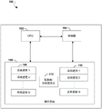
FIG. 1A is a block diagram of a computing device used in accordance with various embodiments.
FIG. 1B is a functional block diagram of an observer/analysis unit for analyzing structural properties of a virtual memory region, in accordance with various embodiments.
FIG. 2 is a diagram of a process address space, in accordance with various embodiments.
3A-3B are diagrams illustrating a heap buffer overflow control hijacking software attack.
4A-4B are diagrams illustrating a heap buffer overflow control hijacking software attack.
Fig. 5 is a diagram illustrating a program return hijacking software attack.
FIG. 6 is a block diagram of a virtual memory region monitoring system in a computing device, in accordance with various embodiments.
FIG. 7 is a component block diagram of a virtual memory region translation tracker in accordance with various embodiments.
Fig. 8 is a process flow diagram illustrating a method for detecting a software attack on a process executing on a computing device in accordance with various embodiments.
FIG. 9 is a process flow diagram illustrating a hardware-based method for tracking virtual memory region translations for processes executing on a computing device, in accordance with various embodiments.
FIG. 10 is a process flow diagram illustrating a software-based method for tracking virtual memory region translations for processes executing on a computing device, in accordance with various embodiments.
Figure 11 is a component block diagram of a mobile communication device suitable for implementing some embodiment methods.
Detailed Description
Various embodiments will be described in detail with reference to the accompanying drawings. Wherever possible, the same reference numbers will be used throughout the drawings to refer to the same or like parts. References to specific examples and implementations are for illustrative purposes, and are not intended to limit the scope of the written description or claims.
As used herein, the term "computing device" refers to any or all of the following: cellular phones, smart phones, personal or mobile multimedia players, personal data assistants, desktop computers, laptop computers, tablet computers, servers, smart phones, smart watches, palmtop computers, wireless email receivers, multimedia internet enabled cellular phones, wireless game controllers, and similar personal or enterprise electronic devices that include a programmable processor and memory.
The computing device executes various applications and system processes, some of which may have low-level privileged access to the computing device, such as root access. These processes may be subject to attacks that control hijacking software, which may attempt to control the computing device at a lower level. Examples of such attacks may include stack or heap buffer overflow attacks and return programming attacks.
Each process has a specific internal memory structure or the geographic location of its internal state is maintained by the operating system. For example, each process has a process address space that is laid out as to where the various instructions and data for that process are stored in memory. Processes typically load the same set of libraries, and library dependencies typically do not change dynamically at runtime. In addition, a process typically executes code and traverses its address space in a predictable manner. This may be particularly true for system services designed to repeatedly process similar sets of requests.
When a control hijacking software attack occurs, the internal memory structure of the target process and the behavior of traversing the address space may change. For example, malware may cause a change in the control flow of a process (i.e., execute a different set of instructions, or execute in a different order). The memory area from which the code is executed may be different.
In general, various embodiments provide systems and methods for monitoring the internal state of a memory structure of a process, or the geography of a process, to detect abnormal execution behavior caused by control hijacking software attacks. The process address space of a process may be divided into a number of Virtual Memory Regions (VMRs), which represent contiguous portions of memory within which data, functions, or instructions are stored. An observer or analyzer unit in the computing device can monitor various structural properties of the VMR of the process executing on the computing device. The monitored structural attributes may include the number of VMRs used by the process, the size of each VMR, changes in the address space layout of the VMR, changes in the access permissions of the VMR, and VMR state transition history. The structural attributes may be independent of the data stored within each VMR.
The monitored structural attributes of the VMR of the process may then be compared to expected structural attributes of the VMR of the process. If the monitored structural attributes deviate from expected structural attributes, this may indicate that the process was hijacked for malicious purposes. The computing device may then take some protective action in response, such as by terminating the process, launching an anti-malware program, or locking some portion of the operating system from the process.
FIG. 1A is a functional block diagram of a computing device 100 suitable for implementing various embodiments. The computing device 100 may be a desktop computer, a laptop computer, a tablet computer, any type of mobile electronic device, a server, or any type of consumer or enterprise electronic device. Computing device 100 may include a Central Processing Unit (CPU)102 for executing software instructions and a memory 104 for storing code and data. The memory 104 may be a non-transitory computer-readable storage medium that stores processor-executable instructions. The memory 104 may store an operating system 106. Several system processes 108 and/or application processes 110 may execute on computing device 100 within operating system 106. Some of the processes 108, 110 may belong to a privileged application or system service that has higher access rights to a low level of the computing device 100 (e.g., root or basic input/output system (BIOS).
The computing device 100 may also include an observer/analyzer unit 112 executing within the operating system 106 that monitors attributes of VMRs of the processes 108, 110. The observer/analyzer unit 112 can collect and monitor structural attributes of the VMR and compare the monitored structural attributes to expected structural attributes of the VMR of the process 108, 110. The observer/analyzer unit 112 can use one or more techniques for monitoring and comparing the structural attributes, including modeling, machine learning, and rule-based analysis. The observer/analyzer unit 112 can generate an output that indicates when one or more processes 108, 110 exhibit abnormal behavior.
FIG. 1B illustrates exemplary logical components and information flow of the observer/analyzer unit 112 of FIG. 1A. The observer/analyzer unit 112 may execute within a processor, such as the CPU 102, and may be configured to characterize expected structural properties and observed structural properties of VMRs of a process using behavioral analysis techniques. The observer/analyzer unit 112 may include an observer unit 120, an extractor unit 122, an analyzer unit 124, and a characterization unit 126.
In various implementations, all or a portion of the observer/analyzer unit 112 can be implemented as part of the observer unit 120, the extractor unit 122, the analyzer unit 124, and the characterization unit 126. Each of the units 120-126 may be a thread, process, daemon, subsystem, or component implemented in software, hardware, or a combination thereof. In various implementations, the units 120-126 may be implemented in: within a portion of an operating system (e.g., within a kernel space, within a user space, etc.), within a separate program or application, within a dedicated hardware buffer or processor, or any combination thereof. In some implementations, one or more of the units 120-126 may be implemented as software instructions executing on one or more processors of the computing device 100.
The characterization unit 126 may be configured to characterize the behavior of a process and the expected structural properties of the VMR used by the process. The characterization unit 126 may generate at least one model based on the observed behavior of the process using the characterized behaviors and the expected structural attributes. The characterization unit 126 may compare the observed behavior to a behavior model. The characterization unit 126 may also aggregate the comparison of the observed behavior of the process by other units with the corresponding behavior models. The characterization unit 126 may determine whether the observed process is behaving abnormally based on the aggregated comparisons. Characterization unit 126 may use the information collected by observer unit 120 to determine structural attributes of the VMR used by the observed process, and use any or all of such information to characterize the behavior of the observed process.
The observer unit 120 can be configured to observe/monitor behavior of a process and determine structural attributes of the VMR based on the observation/monitoring. Structural attributes may include the number of VMRs used by a process, the size of each VMR, changes in the address space layout of the VMR, changes in access rights of the VMR, and VMR state transition history.
In some implementations, the extractor unit 122 can be configured to generate a behavior vector from a log file generated by the observer unit 120. The behavior vectors may be used as identifiers to enable a behavior analysis system (e.g., analyzer unit 124) to quickly identify, or analyze real-time process behavior and VMR structural attributes. In some implementations, the extractor unit 122 may be configured to generate behavior vectors of size "n", each mapping real-time process behavior and VMR structural attributes into an n-dimensional space. In an exemplary implementation, the extractor unit 122 may be configured to generate a behavior vector to include information that may be input to the feature/decision nodes in the characterization unit 126 to generate an answer to a query for one or more features regarding the VMR structural attributes of the process, the one or more features characterizing the behavior of the process.
The extractor unit 122 may send the generated behavior vector to the analyzer unit 124 (e.g., via a memory write operation, a function call, etc.). The analyzer unit 124 may be configured to apply the behavior vector to a classifier model to characterize the observed behavior of the process, e.g., whether a monitored structural attribute of the VMR used by the process indicates whether the process is legitimate, non-legitimate, or anomalous.
The classifier model may be a behavior model that includes data and/or information structures (e.g., feature vectors, behavior vectors, component lists, etc.) that may be used to evaluate particular features or aspects of process activity. The classifier model may also include decision criteria for monitoring the number of VMRs used by the process. The classifier models may be pre-installed on the computing device 100, downloaded or received from a network server, generated in the observer unit 120, or any combination thereof. The classifier model may be generated by using behavioral modeling techniques, machine learning algorithms, or other methods of generating classifier models.
In some implementations, the classifier model may be specific to certain types of processes (e.g., application processes and system processes). Such classifier models may include focused data models that include/only test process-specific features/entries that are determined to be most relevant to evaluating the behavior of a particular process.
In some implementations, the analyzer unit 124 may be configured to adjust the granularity or level of detail of the features of the process evaluated by the analyzer unit 124, particularly when the analysis of the process behavior is uncertain. For example, the analyzer unit 124 may be configured to notify the observer unit 120 in response to determining that it cannot characterize the behavior of the process. In response, observer unit 120 can change the monitored VMR structural properties and/or adjust the granularity of their observations (i.e., the level of detail and/or frequency with which the observed behavioral features are observed) based on notifications sent from analyzer unit 124 (e.g., based on notifications of analysis results of the observed behavioral features).
In various implementations, the classifier model may be an enhanced set of decision trees based on particular characteristics of process behavior. An enhanced decision tree is a one-level decision tree that may have only one node (i.e., one test question or test condition) and weight values, and may be suitable for light, non-processor intensive binary classification of data/behavior. Applying a behavior vector to an enhanced decision tree may result in a binary answer (e.g., 1 or 0, yes or no, etc.). For example, the questions/conditions tested by the enhanced decision tree may include: the response to these problems may be binary, whether the words or sounds detected by the device microphone are characteristic of an RF-sensitive environment, or whether an image of another device captured by the device camera is recognizable as a hazard that produces radio frequency emissions. Enhanced decision trees are effective because these models do not require significant processing resources to generate binary responses. The enhanced decision tree may also be highly parallelizable, which enables multiple trees to be applied or tested in parallel/simultaneously (e.g., by multiple cores or processors in a unit, computing device, or system).
FIG. 2 illustrates an example of a process address space 200 of a process (e.g., one of processes 108, 110) that may be executing on computing device 100. The operating system on the computing device typically establishes a separate address space for each active process executing on the computing device. The process address space 200 may include several address ranges or Virtual Memory Areas (VMAs). Each VMA may be used to map and load a given portion of a process into memory. Process address space 200 may be sparse or dense depending on how much code is loaded by the process, how many stacks and heaps are used, and how many libraries are loaded.
The process address space 200 may contain VMAs for the user stack 204. The user stack 204 is a memory area for storing temporary variables created by processes. The user stack 204 may be constructed as a first-in-last-out (FILO) data structure, where variables are stored in the stack from bottom to top and are popped from the top of the stack first. The process address space 200 may also include VMAs for libc libraries 208 and other shared libraries 206. The libraries 206, 208 may contain several shared functions used by several processes. Each process may load a copy of the libraries 206, 208 into its address space. The process address space 200 may also include VMAs for the heap 210, which may be used to store global variables and other information. For example, malloc () and free () functions may be used to add and remove information from heap 210. The process address space 200 may also include a VMA for a body 212, which body 212 may include the subject code of the process.
The VMA may be subdivided into multiple Virtual Memory Regions (VMRs), where each VMR may be a contiguous range of addresses within the VMA that store data, instructions, or functions. For example, a VMA for the libc library 208 may contain a VMR208a, and the VMR208a may contain, for example, a particular function in the libc library 208.
The CPU of the computing device may use a Program Counter (PC)214 that contains the address of the instruction that the process is currently executing. PC214 can jump around process address space 200 as different portions of the address space are called. For example, when a function is called, PC214 can start in body 212 and move to libc library 208. PC214 can then move to stack 204 to read or write temporary variables used within the function, and then move back to body 212.
The process address space 200 may be subject to several different types of control hijacking software attacks, which are shown in fig. 3A-5. One type of attack is a stack buffer overflow attack or "stack overflow" attack. Exemplary code for illustrating a stack buffer overflow attack is shown herein:

FIG. 3A shows what the stack 302 can load when a foo function is called. The stack 302 may include: memory allocated for the variable buf [128], followed by the function's return address, stack frame pointer, and input str parameters. Flow diagram 304 illustrates the normal behavior of a process when a foo function is called from the body of the process using stack 302. The process can start in the body and then move to the VMR of the libc library (libc.R1) to call the strcpy function, to another VMR of the libc library (libc.R3) to call the printf function, and then move back to the body of the process.
In a stack buffer overflow attack, the target of the attacker is: overflow a buffer on a stack, inject some code into the stack, and modify a return address on the stack to jump to the injected code. FIG. 3B illustrates a stack 312 that has been compromised by malware. Malware may call the foo function with a string variable that is larger than the allocated variable buf [128] to cause a buffer overflow that covers other portions of the stack 312 or the VMR. The input variables may contain the injected code (i.e., Exec ("/bin/sh")) and a return address pointing to the injected code. Thus, when the program counter reaches the return address in the stack 312, it jumps to the injected code and executes it.
The flow diagram 314 shows the abnormal behavior of a process when a foo function is called from the body of the process using the stack 312. The process can start in the body and then move to the VMR of libc library (libc. r1) to call strcpy function. However, the return address of the strcpy function has been covered by the buffer overflow, and it now points to the injected code (Exec ("/bin/sh") in stack 312. The program counter will jump to the injected code and execute it.
Another type of control hijacking attack is a heap buffer overflow attack. Exemplary code for illustrating a heap buffer overflow attack is shown herein:

FIG. 4A shows what the heap 402 can load when the do _ compare function is called. The stack 402 may include: memory allocated for the variable buf [128], followed by a pointer to the function. Flow chart 404 shows the normal behavior of a process when the do _ compare function is called from its body using heap 402. The process can start in the body and then move to the VMR of the libc library (libc. R1) to call the strcpy function and then move back to another VMR of the body to execute the rest of the function.
In a heap cache overflow attack, the target of the attacker is: the method includes overflowing allocated buffers on the heap, injecting some code in another portion of memory, and overriding a function pointer to redirect the function call to the injected code. FIG. 4B shows a heap 412 that has been compromised by malware. The malware may invoke the do _ compare function with a char variable larger than the allocated buffer to cause a buffer overflow that overrides the function pointer stored in the heap 412 with another function pointer to the injected code. Thus, when the program counter reaches the function pointer in heap 412, it jumps to the injected code and executes it.
Another type of control-hijacking attack is a return-on-programming attack (return-on-programming attack) that strings together small blocks of pre-existing code in a computing device to execute malicious functions. The existing code of a tile may be referred to as a program Return (ROP) gadget. The ROP gadgets are tiny sequences of code that end with a return instruction and may be in the body of a shared library or process address space loaded by a process. ROP gadgets may be invoked in a particular sequential order to fetch a shell or to complete other malicious tasks.
FIG. 5 shows a stack 502 that has been compromised to sequentially invoke several ROP gadgets (gadgets). Stack 502 may be compromised via buffer overflow similar to that described with reference to fig. 3B. In this case, the stack 502 is rewritten to include addresses to several ROP gadgets in a particular order, along with pseudo stack frame pointers. Flow chart 504 shows the abnormal behavior of the process when executing from stack 502. The process may begin in the body and then move to the address stored in the stack 502. However, the top address in stack 502 now points to ROP gadget 1, which could be located in a VMR in the libc library (e.g., libc.Ri). After ROP gadget 1 is executed, the program counter is returned to the stack 502 and then moved to ROP gadget 2, which ROP gadget 2 may be located in another VMR in the libc library (e.g., libc. The computing device may execute each ROP gadget in the order in which it was arranged in stack 502.
Other types of control hijacking attacks may include integer overflow based attacks, which may work similar to stack or heap buffer overflow attacks. The buffer allocation for integer variables in a function may be allocated to be smaller than the variable, which may result in overflow. A function pointer may be inserted into the overflow that points to the injected malicious code.
All of these types of control hijacking software attacks typically change the way a process allocates and traverses the process address space, such as by changing stacks, heaps, or pointers to portions of the address space. A process may typically have fairly predictable routines and thus may have predictable behavior for allocating or traversing the process address space. Thus, the address space of a process may be monitored and compared to expected behavior, and abnormal behavior indicative of a control hijacking attack may be detected.
FIG. 6 illustrates a block diagram of an exemplary implementation of a VMR monitoring system 600 in a computing device. The VMR monitoring system 600 may include an observer/analyzer unit 112 that takes as input monitored structural properties 602-610 of a number of VMRs used by a process and compares the monitored structural properties with expected structural properties of the VMRs of the process. The comparison and analysis may be based on a set of rules, or may be accomplished through machine learning by modeling the expected structural attributes of the VMR and the address space of the process. If the monitored structural properties do not match the expected structural properties, the observer/analyzer unit 112 can send an output 614 to other components in the computing device. Output 614 may include instructions for taking protective actions, such as terminating the process, locking portions of the operating system from the process, initiating an anti-malware program, or other actions.
A process may have an associated address space that includes several VMRs. These VMRs may include stacks, heaps, libraries, and portions of the body of a process. For example, each VMR may correspond to a function, variable, pointer, or other discrete portion of data or instructions stored in the process address space.
Structural attributes of a VMR may include attributes that define or describe the structure, allocation, geography, or state transition history of the VMR over time. The structural attributes may be data independent. In other words, the actual data or content stored within the VMR may not be included as a structural attribute, and changes to the structural attributes of the VMR may not be dependent on changes to the data stored in the VMR. The monitored structural properties 602-610 are non-limiting examples of various structural properties that may be monitored by the observer/analyzer unit 112.
One monitored structural attribute 602 may be the number of VMRs present in the address space. In normal execution, a process may typically use a certain number of VMRs. Controlling a hijacking attack may involve allocating a new portion of memory to store external or injected code or data. Thus, a change in the number of VMRs may indicate anomalous behavior resulting from a control hijacking software attack. The number of VMRs may be monitored by a kernel mapper that calls a function (e.g., do _ mmap ()) whenever a new VMR is created.
Another monitored structural attribute 604 may be the size of each VMR. For example, memory allocated for use by certain variables of a process may be the same between multiple executions, so a change in VMR size may indicate abnormal behavior caused by a control hijacking software attack (e.g., an attack that artificially creates a buffer overflow). The size of the VMR can be monitored by the kernel mapper, the call to the malloc () function, and the addition of a new function in the library of the process address space.
Another monitored structural attribute 606 may be an address space layout change of the process. A process can typically arrange its address space with specific internal structures such that VMRs are in the same location with respect to each other and the layout does not change between executions. Thus, a change in the address space layout may indicate abnormal behavior caused by a control hijacking software attack. A process's address space layout change may be monitored by a kernel mapper.
Another monitored structural attribute 608 may be a change in access rights of the VMR. Each VMR may be assigned access rights by a process that typically does not change between executions. Thus, a change in VMR access rights may represent anomalous behavior resulting from a control hijacking software attack. Access rights changes to the VMR may be monitored by a kernel virtual memory manager, which may be invoked whenever VMR rights change.
Another monitored structural attribute 610 may be VMR state transition history of the process over time. The process may navigate through the various VMRs in a predictable order that does not change between executions. Thus, when a process makes a series of unexpected state transitions between VMRs, this may represent anomalous behavior resulting from a control hijacking software attack. The VMR state transition history may be monitored by a hardware-based or software-based solution, which is described in further detail with reference to fig. 7, 9, and 10.
FIG. 7 illustrates a hardware implementation of VMR conversion for monitoring processes executing on a computing device. System 700 includes a CPU core 702, the core 702 executing the process and maintaining a program counter for the process. The system 700 may also include a VMR kernel driver 704 that maintains a memory range of VMRs for various processes executing on the computing device. The system 700 may also include a VMR tracker hardware block 706. The VMR tracker hardware block 706 may include a VMR transition recorder 712 that receives the program counter from the CPU core 702 and the current Process ID (PID) and VMR range from the VMR kernel driver 704. VMR tracker hardware block 706 may store several VMR tables 710, which VMR tables 710 may include a table for each process executing on the computing device indexed by the PID. Each table may store VMRs assigned by the process and the last known VMR in which the process is executing.
Periodically, the VMR switch recorder 712 may receive as inputs the VMR range, PID, and/or program counter. These inputs identify the process to be monitored and the current instruction pointed to by the program counter. VMR conversion recorder 712 may compare the input information to VMR table 710 to determine whether the monitored process is still in the same VMR or has been converted to a different VMR (e.g., a function call to a library function from the body of the process). If there are VMR transitions, then VMR transition recorder 712 may record the VMR transitions and store them in data cache 708. The VMR translation and PID may also be sent to the VMR kernel driver 704. In this manner, the VMR tracker hardware block 706 may detect and monitor VMR transitions in processes executing on the computing device.
Although the VMR tracker hardware block 706 is a hardware implementation for monitoring VMR state transition history, VMR state transition history may alternatively be monitored by software. Continued software monitoring of VMR state transitions can be resource intensive and can affect the operation of other processes on the computing device. However, there are several ways to monitor VMR state transitions in a non-continuous manner, which may be implemented alone or in combination.
For example, in selectively tracking VMR state transitions, monitoring may be initiated only for certain execution processes of interest. Other execution processes may not be monitored. The tracking software may monitor the program counter of the process of interest. In periodic tracking, the tracking software may periodically sample the program counter of the process according to a timer thread. In a multi-CPU core system, a timer thread may be connected to a CPU on which no process is running. The period of the timer thread may be adjustable so that the periodicity may be tailored to specific process behavior and reduce the chance of losing VMR state transitions.
In opportunistic tracking, the VMR kernel driver may receive control of the CPU on which the process is executing. In this scenario, the VMR kernel driver may sample the program counter and track VMR state transitions. For example, the VMR kernel driver may receive processor control during interrupt arrival, context switching, signal generation, and system calls. In paging error based tracking, the tracking software may set non-current VMRs to be non-executable (e.g., read-only) and whenever the process jumps to a new VMR, there will be a paging error. The tracking software may log the state transition whenever a paging error is detected, set the new VMR to executable, and set the old VMR to non-executable.
Fig. 8 illustrates a method 800 for detecting a software attack on a process executing on a computing device, in accordance with various embodiments. The method 800 may be implemented by a processor of a computing device (e.g., the CPU 102 of the computing device 100 in fig. 1A).
In block 802, a processor may monitor structural attributes of a plurality of virtual memory regions of a process executing on a computing device. The process may have an associated address space that may be divided into several VMRs. A VMR may be a contiguous portion of memory that stores data, instructions, or functions that may be found in a stack, heap, library, body, or other portion of the address space of the process. The monitored structural attributes may include the number of VMRs used by the process, the size of each VMR, changes in the address space layout of the VMR, changes in the access permissions of the VMR, and VMR state transition history.
In block 804, the processor may compare the monitored structural attributes of the plurality of VMRs to expected structural attributes of the plurality of VMRs of the process. The computing device may have previously analyzed the expected behavior of the process (i.e., performed with the crossbow having interference from control hijacking attacks) when allocating, using, and transitioning between VMRs, and has built a model or set of rules that define the expected structural properties of the VMR for the process. The processor may compare the monitored structural attributes to expected structural attributes using a mathematical model, rule-based comparison, or other methods.
In determination block 806, the processor may determine whether the monitored structural attributes of the multiple VMRs of the process represent abnormal behavior based on the comparison between the monitored structural attributes and the expected structural attributes. For example, the processor may use a mathematical model to generate a value representing the similarity between the monitored structural property and the expected structural property, and compare the value to a threshold representing an acceptable degree of similarity. If the value is below a threshold, the monitored structural property may indicate abnormal behavior. In another example, the processor may apply a set of rules to the monitored structural attributes and determine whether all of the rules are satisfied by the monitored structural attributes. If the monitored structural attributes do not satisfy one or more rules, the monitored structural attributes may represent anomalous behavior.
In response to determining that the monitored structural attributes do not represent abnormal behavior ("no" at decision block 806), the processor may continue to monitor the structural attributes of the plurality of VMRs for as long as the process is executing (i.e., return to the operations in block 802). In response to determining that the monitored structural attributes represent abnormal behavior (determination block 806 — yes), the processor may initiate a protective action in block 808. For example, the processor may terminate the process, lock portions of the operating system from the process, initiate anti-malware programs, or other operations. In this manner, method 800 provides a way to monitor control of a process for hijacking software attacks by monitoring the structural properties of VMRs in the address space of the process.
FIG. 9 illustrates a method 900 for hardware-based tracking of VMR state transition history of processes executing on a computing device, in accordance with various embodiments. The method 900 may be performed by a processor of a computing device (e.g., the CPU 102 of the computing device 100 in fig. 1A) or by a processor in VMR tracker hardware in the computing device (e.g., the VMR tracker hardware block 706 in fig. 7).
At block 902, the processor may store information about the current VMR in which a process on the computing device is executing. The process may use an address space that includes several VMRs that include contiguous portions representing memory for storing data, functions, or instructions. The program counter of a process may point to the current VMR in which the process is executing. The stored information may include the PID of the processor, the memory ranges of all VMRs in the process 'address space, and the current VMR (e.g., a function in the process's body) in which the process is executing. For example, this information may be stored in the form of a table, one for each process that the processor is monitoring. The information may be stored in a data store in the VMR tracker hardware.
At block 904, the processor may receive new information about the instructions currently being executed by the process. For example, the processor may occasionally receive updated program counters from the CPU on which the process is executing. The processor may also receive the PID of the process and the current memory range of the VMR from the VMR kernel driver.
In determination block 906, the processor may determine whether the process has experienced a VMR state transition based on the new information. The processor may use the program counter, the PID, and the current memory range of the VMR to determine whether the process has transitioned to another VMR. For example, if the last stored current VMR of a process is in the context of the process, the processor may determine from the program counter whether the process is still executing within the same VMR or has transitioned to another VMR (e.g., a function call to a function stored in a library).
In response to determining that the process is not undergoing a VMR state transition ("no" at decision block 906), the processor may continue to receive new information regarding the instructions currently being executed by the process at block 904. In response to determining that the process has undergone a VMR state transition (determination block 906 — yes), the processor may record the VMR state transition in block 908. For example, a processor may store a VMR from which the process is translated and a VMR to which the processor is translated. Subsequently, the processor may store the new current VMR information in block 902. In this manner, method 900 provides a hardware-based implementation for tracking VMR state transition history for a process.
FIG. 10 illustrates a method 1000 for software-based tracking of VMR state transition history for processes executing on a computing device, in accordance with various embodiments. The method 1000 may be implemented by a processor of a computing device (e.g., the CPU 102 of the computing device 100 in fig. 1A).
At block 1002, the processor may store information about the current VMR in which a process on the computing device is executing. The process may use an address space that includes a number of VMRs representing contiguous portions of memory for storing data, functions, or instructions. The program counter for the process may point to the current VMR in which the process is executing. The stored information may include: the PID of the processor, the memory ranges of all VMRs in the process 'address space, and the current VMR (e.g., a function in the process's body) in which the process is executing. For example, this information may be stored in the form of a table, one for each process that the processor is monitoring.
At block 1004, the processor may implement one or more VMR tracking policies on the process. Examples of VMR tracking policies may include: selective tracking (tracking only processes of particular interest); periodic tracking (periodic collection of VMR state transition information); opportunistic tracking (VMR state transition information is collected when the VMR kernel driver gains control of the processor on which the process is executing); and paging error based tracking (setting all non-current VMRs as non-executable and tracking paging errors when a VMR state transition occurs).
In determination block 1006, the processor may determine whether the process has experienced a VMR state transition. The processor may determine whether a VMR state transition has occurred according to one or more VMR transition tracking policies. For example, a VMR state transition may be detected when a program counter of a process points to a new VMR, or whether a paging error has been missed in a paging error based trace.
In response to determining that the process has not experienced a VMR state transition ("no" at determination block 1006), the processor may continue to implement one or more VMR tracking policies for the process in block 1004. In response to determining that the process has experienced a VMR state transition (determination block 1006 — yes), the processor may record the VMR state transition in block 1008. For example, the processor may store the VMR from which the process is converted and the VMR to which the process is converted. Subsequently, the processor may store the new current VMR information in block 1002. In this manner, method 1000 provides a software-based implementation for tracking VMR state transition history for a process.
Various embodiments may be implemented in any of a variety of computing devices, an example of which is shown in fig. 11 (e.g., communications device 1100). In various implementations, the communication device 1100 may be similar to the computing device 100 described herein with reference to fig. 1A. As such, the communication device 1100 may implement some or all of the methods 800, 900, and 1000 in fig. 8-10.
The communication device 1100 can include a processor 1102 coupled to a touchscreen controller 1104 and an internal memory 1106. The processor 1102 may be one or more multi-core integrated circuits designated for general or specific processing tasks. The internal memory 1106 may be volatile or non-volatile memory, and may also be secure and/or encrypted memory, or unsecure and/or unencrypted memory, or any combination thereof. The touchscreen controller 1104 and the processor 1102 may also be coupled to a touchscreen panel 1112, such as a resistive sensing touchscreen, a capacitive sensing touchscreen, an infrared sensing touchscreen, and the like. Additionally, the display of the communication device 1100 does not require touch screen capability.
The communication device 1100 may have a cellular network transceiver 1108, the cellular network transceiver 1108 being coupled to the processor 1102 and an antenna 1110 and being configured to transmit and receive cellular communications. The transceiver 1108 and antenna 1110 may be used with the circuits mentioned herein to implement the various embodiment methods. The communication device 1100 may include one or more SIM cards 1116 coupled to the transceiver 1108 and/or the processor 1102 and may be configured as described herein. The communication device 1100 may include a cellular network wireless modem chip 1117 that enables communication via a cellular network and may be coupled to a processor.
The communication device 1100 may also include a speaker 1114 for providing audio output. The communication device 1100 may also include a housing 1120, the housing 1120 being constructed of plastic, metal, or a combination of materials for housing all or a portion of the components discussed herein. The communication device 1100 may include a power supply 1122, such as a disposable or rechargeable battery, coupled to the processor 1102. The rechargeable battery may also be coupled to the peripheral device connection port to receive a charging current from a source external to the communication device 1100. The communication device 1100 may also include physical buttons 1124 for receiving user input. The communication device 1100 can also include a power button 1126 for turning the communication device 1100 on and off.
The foregoing method descriptions and process flow diagrams are provided merely as illustrative examples and are not intended to require or imply that the operations in the various embodiments and implementations must be performed in the order presented. As will be appreciated by those of skill in the art, the order of the operations in the foregoing embodiments and implementations may be performed in any order. Words such as "after," "then," "next," etc. are not intended to limit the order of the steps; these words are used only to guide the reader through the description of the methods. Furthermore, any reference to claim elements in the singular (e.g., using the articles "a," "an," or "said") should not be construed as limiting the element to the singular.
The various illustrative logical blocks, units, circuits, and algorithm operations described in connection with the embodiments and implementations disclosed herein may be implemented as electronic hardware, computer software, or combinations of both. To clearly illustrate this interchangeability of hardware and software, various illustrative components, blocks, units, circuits, and operations have been described above generally in terms of their functionality. Whether such functionality is implemented as hardware or software depends upon the particular application and design constraints imposed on the overall system. Skilled artisans may implement the described functionality in varying ways for each particular application, but such implementation decisions should not be interpreted as causing a departure from the scope of the claims.
The hardware used to implement the various illustrative logical devices, logical blocks, units, and circuits described in connection with the embodiments and implementations disclosed herein may be implemented in or performed by various processors or combinations of processors and circuits. Examples of processors and circuits that may implement the various embodiments include a general purpose processor, a Digital Signal Processor (DSP), an Application Specific Integrated Circuit (ASIC), a Field Programmable Gate Array (FPGA) and other programmable logic devices, discrete gate or transistor logic, discrete hardware components, or any combination thereof designed to perform the functions described herein. A general-purpose processor may be a microprocessor, but, in the alternative, the processor may be any conventional processor, controller, microcontroller, or state machine. A processor may also be implemented as a combination of computing devices, e.g., a combination of a DSP and a microprocessor, a plurality of microprocessors, one or more microprocessors in conjunction with a DSP core, or any other such configuration. Alternatively, some operations or methods may be performed by circuitry that is specific to a given function.
In one or more example embodiments and implementations, the functions described may be implemented in hardware, software, firmware, or any combination thereof. If implemented in software, the functions may be stored as one or more instructions or code on a non-transitory computer-readable storage medium or a non-transitory processor-readable storage medium. The operations of a method or algorithm disclosed herein may be embodied in a processor-executable software unit resident on a non-transitory computer-readable or processor-readable storage medium. A non-transitory computer-readable or processor-readable storage medium may be any storage medium that can be used to store desired program code in the form of instructions or data structures and that can be accessed by a computer or processor. By way of example, and not limitation, such non-transitory computer-readable or processor-readable storage media may include RAM, ROM, EEPROM, flash memory, CD-ROM or other optical disk storage, and magnetic disk storage or other magnetic storage devices. Disk and disc, as used herein, includes Compact Disc (CD), laser disc, optical disc, Digital Versatile Disc (DVD), floppy disk and blu-ray disc where disks usually reproduce data magnetically, while discs reproduce data optically with lasers. Combinations of the memory described herein are also included within the scope of non-transitory computer-readable and processor-readable media. Additionally, the operations of a method or algorithm may reside as one or any combination or set of codes and/or instructions on a non-transitory processor-readable storage medium and/or computer-readable storage medium, which may be incorporated into a computer program product.
The previous description of various embodiments and implementations is provided to enable any person skilled in the art to make or use the claims. Various modifications to these embodiments will be readily apparent to those skilled in the art, and the generic principles defined herein may be applied to some embodiments without departing from the scope of the claims. Thus, the present disclosure is not intended to be limited to the embodiments and implementations shown herein but is to be accorded the widest scope consistent with the following claims and the principles and novel features disclosed herein.
Claims (28)
1. A method for detecting a software attack on a process executing on a computing device, comprising:
monitoring structural attributes of a plurality of virtual memory regions used by the process, wherein the monitored structural attributes include:
an address space layout of the plurality of virtual memory regions;
a number of virtual memory regions included in the plurality of virtual memory regions; or
A size of a virtual memory region included in the plurality of virtual memory regions;
comparing the monitored structural attributes to expected structural attributes of the plurality of virtual memory regions; and
determining whether the monitored structural attributes represent abnormal behavior of the process based on the comparison between the monitored structural attributes and the expected structural attributes.
2. The method of claim 1, further comprising:
a protective action is initiated in response to determining that the monitored structural attribute represents an abnormal behavior.
3. The method of claim 1, wherein monitoring the structural attributes of the plurality of virtual memory regions used by the process further comprises:
monitoring for a change in the address space layout;
monitoring for changes in access permissions of the plurality of virtual memory regions; or
Monitoring a state transition history of the plurality of virtual memory regions.
4. The method of claim 1, wherein monitoring the structural attributes of the plurality of virtual memory regions used by the process comprises:
storing information about a current virtual memory region in which the process is executing;
receiving new information about instructions currently being executed by the process;
determining whether there is a transition from the current virtual memory region based on the received new information; and
in response to determining that there is the transition from the current virtual memory region, recording the transition from the current virtual memory region to a new virtual memory region.
5. The method of claim 4, wherein receiving the new information about the instruction currently being executed by the process comprises receiving a program counter value and a process identifier.
6. The method of claim 1, wherein monitoring structural attributes of the plurality of virtual memory regions used by the process comprises:
storing information about a current virtual memory region in which the process is executing;
implementing one or more virtual memory region tracking policies on the plurality of virtual memory regions;
determining whether there is a transition from the current virtual memory region based on the one or more virtual memory region tracking policies; and
in response to determining that there is the transition from the current virtual memory region, recording a transition from the current virtual memory region to a new virtual memory region.
7. The method of claim 6, wherein implementing the one or more virtual memory region tracking policies on the plurality of virtual memory regions comprises implementing selective tracking, periodic tracking, opportunistic tracking, or paging error based tracking on the plurality of virtual memory regions.
8. The method of claim 1, wherein comparing the monitored structural attributes of the plurality of virtual memory regions to the expected structural attributes comprises: applying a set of rules to the monitored structural attributes, wherein the set of rules is based on the expected structural attributes of the plurality of virtual memory regions.
9. The method of claim 1, wherein comparing the monitored structural attributes of the plurality of virtual memory regions to the expected structural attributes comprises:
modeling the expected structural attributes of the plurality of virtual memory regions to generate a model; and is
Comparing the monitored structural attributes to the model.
10. A computing device, comprising:
a memory comprising a plurality of virtual memory regions; and
a processor coupled to the memory and configured with processor-executable instructions to:
monitoring structural attributes of the plurality of virtual memory regions used by processes executing on the computing device, wherein the monitored structural attributes include:
an address space layout of the plurality of virtual memory regions;
a number of virtual memory regions included in the plurality of virtual memory regions; or
A size of a virtual memory region included in the plurality of virtual memory regions;
comparing the monitored structural attributes to expected structural attributes of the plurality of virtual memory regions; and
determining whether the monitored structural attributes represent abnormal behavior of the process based on the comparison between the monitored structural attributes and the expected structural attributes.
11. The computing device of claim 10, wherein the processor is further configured with processor-executable instructions to:
a protective action is initiated in response to determining that the monitored structural attribute represents an abnormal behavior.
12. The computing device of claim 10, wherein the processor is further configured with processor-executable instructions such that monitoring the structural attributes of the plurality of virtual memory regions used by the process is performed by:
monitoring for a change in the address space layout;
monitoring for changes in access permissions of the plurality of virtual memory regions; or
Monitoring a state transition history of the plurality of virtual memory regions.
13. The computing device of claim 10, wherein the processor is further configured with processor-executable instructions to monitor structural attributes of the plurality of virtual memory regions used by the process by:
storing information about a current virtual memory region in which the process is executing;
receiving new information about instructions currently being executed by the process;
determining whether there is a transition from the current virtual memory region based on the received new information; and
in response to determining that there is the transition from the current virtual memory region, recording the transition from the current virtual memory region to a new virtual memory region.
14. The computing device of claim 13, wherein the processor is configured with processor-executable instructions to perform operations such that receiving the new information about the instructions currently being executed by the process comprises receiving a program counter value and a process identifier.
15. The computing device of claim 10, wherein the processor is further configured with processor-executable instructions to perform operations such that monitoring structural attributes of the plurality of virtual memory regions used by the process comprises:
storing information about a current virtual memory region in which the process is executing;
implementing one or more virtual memory region tracking policies on the plurality of virtual memory regions;
determining whether there is a transition from the current virtual memory region based on the one or more virtual memory region tracking policies; and
in response to determining that there is the transition from the current virtual memory region, recording a transition from the current virtual memory region to a new virtual memory region.
16. The computing device of claim 15, wherein the processor is further configured with processor-executable instructions to perform operations such that implementing the one or more virtual memory region tracking policies on the plurality of virtual memory regions comprises implementing selective tracking, periodic tracking, opportunistic tracking, or paging error based tracking on the plurality of virtual memory regions.
17. The computing device of claim 10, wherein the processor is further configured with processor-executable instructions to perform operations such that comparing the monitored structural attributes to the expected structural attributes for the plurality of virtual memory regions comprises:
applying a set of rules to the monitored structural attributes, wherein the set of rules is based on the expected structural attributes of the plurality of virtual memory regions.
18. The computing device of claim 10, wherein the processor is further configured with processor-executable instructions to perform operations such that comparing the monitored structural attributes to the expected structural attributes for the plurality of virtual memory regions comprises:
modeling the expected structural attributes of the plurality of virtual memory regions to generate a model; and is
Comparing the monitored structural attributes to the model.
19. A non-transitory computer readable storage medium having stored thereon processor-executable software instructions configured to cause a processor of a computing device to perform operations comprising:
monitoring structural attributes of a plurality of virtual memory regions used by processes executing on the computing device, wherein the monitored structural attributes include:
an address space layout of the plurality of virtual memory regions;
a number of virtual memory regions included in the plurality of virtual memory regions; or
A size of a virtual memory region included in the plurality of virtual memory regions;
comparing the monitored structural attributes to expected structural attributes of the plurality of virtual memory regions; and
determining whether the monitored structural attributes represent abnormal behavior of the process based on the comparison between the monitored structural attributes and the expected structural attributes.
20. The non-transitory computer readable storage medium of claim 19, wherein the stored processor-executable software instructions are configured to cause the processor to perform operations further comprising:
a protective action is initiated in response to determining that the monitored structural attribute represents an abnormal behavior.
21. The non-transitory computer readable storage medium of claim 19, wherein the stored processor-executable software instructions are configured to cause the processor to perform operations such that monitoring the structural attributes of the plurality of virtual memory regions used by the process further comprises:
monitoring for a change in the address space layout;
monitoring for changes in access permissions of the plurality of virtual memory regions; or
Monitoring a state transition history of the plurality of virtual memory regions.
22. The non-transitory computer readable storage medium of claim 19, wherein the stored processor-executable software instructions are configured to cause the processor to perform operations such that monitoring structural attributes of the plurality of virtual memory regions used by the process comprises:
storing information about a current virtual memory region in which the process is executing;
receiving new information about instructions currently being executed by the process;
determining whether there is a transition from the current virtual memory region based on the received new information; and
in response to determining that there is the transition from the current virtual memory region, recording the transition from the current virtual memory region to a new virtual memory region.
23. The non-transitory computer readable storage medium of claim 22, wherein the stored processor-executable software instructions are configured to cause the processor to perform operations such that receiving the new information about the instruction currently being executed by the process comprises receiving a program counter value and a process identifier.
24. The non-transitory computer readable storage medium of claim 19, wherein the stored processor-executable software instructions are configured to cause the processor to perform operations such that monitoring structural attributes of the plurality of virtual memory regions used by the process comprises:
storing information about a current virtual memory region in which the process is executing;
implementing one or more virtual memory region tracking policies on the plurality of virtual memory regions;
determining whether there is a transition from the current virtual memory region based on the one or more virtual memory region tracking policies; and
in response to determining that there is the transition from the current virtual memory region, recording a transition from the current virtual memory region to a new virtual memory region.
25. The non-transitory computer readable storage medium of claim 24, wherein the stored processor-executable software instructions are configured to cause the processor to perform operations such that implementing the one or more virtual memory region tracking policies on the plurality of virtual memory regions comprises implementing selective tracking, periodic tracking, opportunistic tracking, or paging error based tracking on the plurality of virtual memory regions.
26. The non-transitory computer readable storage medium of claim 19, wherein the stored processor-executable software instructions are configured to cause the processor to perform operations such that comparing the monitored structural attributes to the expected structural attributes of the plurality of virtual memory regions comprises:
applying a set of rules to the monitored structural attributes, wherein the set of rules is based on the expected structural attributes of the plurality of virtual memory regions.
27. The non-transitory computer readable storage medium of claim 19, wherein the stored processor-executable software instructions are configured to cause the processor to perform operations such that comparing the monitored structural attributes to the expected structural attributes of the plurality of virtual memory regions comprises:
modeling the expected structural attributes of the plurality of virtual memory regions to generate a model; and is
Comparing the monitored structural attributes to the model.
28. A computing device, comprising:
means for monitoring structural attributes of a plurality of virtual memory regions used by a process executing on the computing device, wherein the monitored structural attributes comprise:
an address space layout of the plurality of virtual memory regions;
a number of virtual memory regions included in the plurality of virtual memory regions; or
A size of a virtual memory region included in the plurality of virtual memory regions;
means for comparing the monitored structural attributes to expected structural attributes of the plurality of virtual memory regions; and
means for determining whether the monitored structural attribute represents abnormal behavior of the process based on the comparison between the monitored structural attribute and the expected structural attribute.
Applications Claiming Priority (5)
| Application Number | Priority Date | Filing Date | Title |
|---|---|---|---|
| US201562219970P | 2015-09-17 | 2015-09-17 | |
| US62/219,970 | 2015-09-17 | ||
| US15/057,336 | 2016-03-01 | ||
| US15/057,336 US10255434B2 (en) | 2015-09-17 | 2016-03-01 | Detecting software attacks on processes in computing devices |
| PCT/US2016/046747 WO2017048426A1 (en) | 2015-09-17 | 2016-08-12 | Detecting software attacks on processes in computing devices |
Publications (2)
| Publication Number | Publication Date |
|---|---|
| CN108027859A CN108027859A (en) | 2018-05-11 |
| CN108027859B true CN108027859B (en) | 2020-03-24 |
Family
ID=58282948
Family Applications (1)
| Application Number | Title | Priority Date | Filing Date |
|---|---|---|---|
| CN201680053767.8A Active CN108027859B (en) | 2015-09-17 | 2016-08-12 | Detecting software attacks on processes in a computing device |
Country Status (7)
| Country | Link |
|---|---|
| US (1) | US10255434B2 (en) |
| EP (1) | EP3350741B1 (en) |
| JP (1) | JP6777732B2 (en) |
| KR (1) | KR102534334B1 (en) |
| CN (1) | CN108027859B (en) |
| TW (1) | TW201717086A (en) |
| WO (1) | WO2017048426A1 (en) |
Families Citing this family (9)
| Publication number | Priority date | Publication date | Assignee | Title |
|---|---|---|---|---|
| GB2547272B (en) * | 2016-02-15 | 2020-07-15 | F Secure Corp | Improving security of computer resources |
| US10891379B2 (en) * | 2016-04-26 | 2021-01-12 | Nec Corporation | Program analysis system, program analysis method and storage medium |
| US10372909B2 (en) * | 2016-08-19 | 2019-08-06 | Hewlett Packard Enterprise Development Lp | Determining whether process is infected with malware |
| US10783246B2 (en) | 2017-01-31 | 2020-09-22 | Hewlett Packard Enterprise Development Lp | Comparing structural information of a snapshot of system memory |
| EP3413531A1 (en) * | 2017-06-07 | 2018-12-12 | Hewlett-Packard Development Company, L.P. | Intrusion detection systems |
| US10706180B2 (en) * | 2017-07-07 | 2020-07-07 | Endgame, Inc. | System and method for enabling a malware prevention module in response to a context switch within a certain process being executed by a processor |
| CN110188540B (en) * | 2019-04-17 | 2021-06-22 | 中国科学院软件研究所 | ROP attack detection method based on control state tracking |
| US20210334373A1 (en) * | 2020-04-22 | 2021-10-28 | Arm Limited | Moderator system for a security analytics framework |
| CN112307475A (en) * | 2020-09-29 | 2021-02-02 | 北京软慧科技有限公司 | System detection method and device |
Citations (2)
| Publication number | Priority date | Publication date | Assignee | Title |
|---|---|---|---|---|
| US7996904B1 (en) * | 2007-12-19 | 2011-08-09 | Symantec Corporation | Automated unpacking of executables packed by multiple layers of arbitrary packers |
| CN103729305A (en) * | 2012-10-11 | 2014-04-16 | 财团法人工业技术研究院 | Method and computer system for memory management on virtual machine system |
Family Cites Families (14)
| Publication number | Priority date | Publication date | Assignee | Title |
|---|---|---|---|---|
| US8955104B2 (en) | 2004-07-07 | 2015-02-10 | University Of Maryland College Park | Method and system for monitoring system memory integrity |
| NO20050564D0 (en) | 2005-02-02 | 2005-02-02 | Tore Lysemose Hansen | Program monitor to identify unauthorized intrusion into computer systems |
| CN101278260B (en) | 2005-06-07 | 2012-07-18 | 威睿公司 | Constraint injection method for immunizing software programs against vulnerabilities and attacks |
| US8271450B2 (en) | 2009-10-01 | 2012-09-18 | Vmware, Inc. | Monitoring a data structure in a virtual machine and determining if memory pages containing the data structure are swapped into or out of guest physical memory |
| US9866426B2 (en) * | 2009-11-17 | 2018-01-09 | Hawk Network Defense, Inc. | Methods and apparatus for analyzing system events |
| US8949169B2 (en) * | 2009-11-17 | 2015-02-03 | Jerome Naifeh | Methods and apparatus for analyzing system events |
| KR101663013B1 (en) | 2010-01-15 | 2016-10-06 | 삼성전자주식회사 | Apparatus and method for detecting code injection attack |
| US9401922B1 (en) * | 2010-12-10 | 2016-07-26 | Verizon Patent And Licensing Inc. | Systems and methods for analysis of abnormal conditions in computing machines |
| CN103620613B (en) * | 2011-03-28 | 2018-06-12 | 迈克菲股份有限公司 | For the system and method for the anti-malware safety based on virtual machine monitor |
| US8584254B2 (en) | 2011-12-08 | 2013-11-12 | Microsoft Corporation | Data access reporting platform for secure active monitoring |
| US9832211B2 (en) * | 2012-03-19 | 2017-11-28 | Qualcomm, Incorporated | Computing device to detect malware |
| WO2015113052A1 (en) * | 2014-01-27 | 2015-07-30 | Webroot Inc. | Detecting and preventing execution of software exploits |
| US9881153B2 (en) * | 2014-06-20 | 2018-01-30 | Leviathan, Inc. | System and method for detection of heap spray attack |
| WO2017023773A1 (en) * | 2015-07-31 | 2017-02-09 | Digital Guardian, Inc. | Systems and methods of protecting data from injected malware |
-
2016
- 2016-03-01 US US15/057,336 patent/US10255434B2/en active Active
- 2016-08-12 JP JP2018513605A patent/JP6777732B2/en active Active
- 2016-08-12 EP EP16758010.9A patent/EP3350741B1/en active Active
- 2016-08-12 WO PCT/US2016/046747 patent/WO2017048426A1/en active Application Filing
- 2016-08-12 KR KR1020187010607A patent/KR102534334B1/en active IP Right Grant
- 2016-08-12 CN CN201680053767.8A patent/CN108027859B/en active Active
- 2016-08-17 TW TW105126184A patent/TW201717086A/en unknown
Patent Citations (2)
| Publication number | Priority date | Publication date | Assignee | Title |
|---|---|---|---|---|
| US7996904B1 (en) * | 2007-12-19 | 2011-08-09 | Symantec Corporation | Automated unpacking of executables packed by multiple layers of arbitrary packers |
| CN103729305A (en) * | 2012-10-11 | 2014-04-16 | 财团法人工业技术研究院 | Method and computer system for memory management on virtual machine system |
Also Published As
| Publication number | Publication date |
|---|---|
| TW201717086A (en) | 2017-05-16 |
| CN108027859A (en) | 2018-05-11 |
| EP3350741A1 (en) | 2018-07-25 |
| KR20180054726A (en) | 2018-05-24 |
| JP2018532187A (en) | 2018-11-01 |
| KR102534334B1 (en) | 2023-05-18 |
| US10255434B2 (en) | 2019-04-09 |
| US20170083702A1 (en) | 2017-03-23 |
| WO2017048426A1 (en) | 2017-03-23 |
| EP3350741B1 (en) | 2019-07-17 |
| JP6777732B2 (en) | 2020-10-28 |
Similar Documents
| Publication | Publication Date | Title |
|---|---|---|
| CN108027859B (en) | Detecting software attacks on processes in a computing device | |
| US9158604B1 (en) | Lightweight data-flow tracker for realtime behavioral analysis using control flow | |
| US9898602B2 (en) | System, apparatus, and method for adaptive observation of mobile device behavior | |
| US9357411B2 (en) | Hardware assisted asset tracking for information leak prevention | |
| US9734333B2 (en) | Information security techniques including detection, interdiction and/or mitigation of memory injection attacks | |
| US20210248234A1 (en) | Malware Clustering Based on Function Call Graph Similarity | |
| US9519533B2 (en) | Data flow tracking via memory monitoring | |
| US10216934B2 (en) | Inferential exploit attempt detection | |
| CN109891422B (en) | Dynamic reputation indicator for optimizing computer security operations | |
| US11762987B2 (en) | Systems and methods for hardening security systems using data randomization | |
| Muttoo et al. | Android malware detection: state of the art | |
| US10515216B2 (en) | Memory layout based monitoring | |
| US10853480B2 (en) | Stack pivot exploit detection and mitigation | |
| Stirparo et al. | In-memory credentials robbery on android phones | |
| US11314855B2 (en) | Detecting stack pivots using stack artifact verification | |
| Nasereddin | A New Approach for Detecting Process Injection Attacks Using Memory Analysis |
Legal Events
| Date | Code | Title | Description |
|---|---|---|---|
| PB01 | Publication | ||
| PB01 | Publication | ||
| SE01 | Entry into force of request for substantive examination | ||
| SE01 | Entry into force of request for substantive examination | ||
| GR01 | Patent grant | ||
| GR01 | Patent grant |