CN107980148B - System and method for fusing images to account for motion compensation - Google Patents
System and method for fusing images to account for motion compensation Download PDFInfo
- Publication number
- CN107980148B CN107980148B CN201680026452.4A CN201680026452A CN107980148B CN 107980148 B CN107980148 B CN 107980148B CN 201680026452 A CN201680026452 A CN 201680026452A CN 107980148 B CN107980148 B CN 107980148B
- Authority
- CN
- China
- Prior art keywords
- image
- pose
- view
- baseline
- current
- Prior art date
- Legal status (The legal status is an assumption and is not a legal conclusion. Google has not performed a legal analysis and makes no representation as to the accuracy of the status listed.)
- Active
Links
- 238000000034 method Methods 0.000 title claims description 32
- 238000003384 imaging method Methods 0.000 claims abstract description 40
- 230000000694 effects Effects 0.000 claims description 6
- 230000009471 action Effects 0.000 claims description 5
- 230000000007 visual effect Effects 0.000 claims description 4
- 230000005236 sound signal Effects 0.000 claims description 3
- 238000002604 ultrasonography Methods 0.000 description 43
- 230000003068 static effect Effects 0.000 description 22
- 239000000523 sample Substances 0.000 description 21
- 206010028980 Neoplasm Diseases 0.000 description 18
- 230000006870 function Effects 0.000 description 16
- 230000004927 fusion Effects 0.000 description 14
- 238000002591 computed tomography Methods 0.000 description 11
- 238000010586 diagram Methods 0.000 description 5
- 210000000056 organ Anatomy 0.000 description 5
- 230000003287 optical effect Effects 0.000 description 4
- 238000004364 calculation method Methods 0.000 description 3
- 238000003780 insertion Methods 0.000 description 3
- 230000037431 insertion Effects 0.000 description 3
- 230000009466 transformation Effects 0.000 description 3
- 230000008569 process Effects 0.000 description 2
- 239000004065 semiconductor Substances 0.000 description 2
- 230000001960 triggered effect Effects 0.000 description 2
- 238000012285 ultrasound imaging Methods 0.000 description 2
- 210000004204 blood vessel Anatomy 0.000 description 1
- 230000008859 change Effects 0.000 description 1
- 238000004590 computer program Methods 0.000 description 1
- 230000001419 dependent effect Effects 0.000 description 1
- 238000002059 diagnostic imaging Methods 0.000 description 1
- 210000001035 gastrointestinal tract Anatomy 0.000 description 1
- 230000003993 interaction Effects 0.000 description 1
- 238000010859 live-cell imaging Methods 0.000 description 1
- 210000004072 lung Anatomy 0.000 description 1
- 238000012986 modification Methods 0.000 description 1
- 230000004048 modification Effects 0.000 description 1
- 238000005457 optimization Methods 0.000 description 1
- 230000002093 peripheral effect Effects 0.000 description 1
- 238000012545 processing Methods 0.000 description 1
- 230000029058 respiratory gaseous exchange Effects 0.000 description 1
- 239000007787 solid Substances 0.000 description 1
- 238000000844 transformation Methods 0.000 description 1
- 230000001131 transforming effect Effects 0.000 description 1
- 238000013519 translation Methods 0.000 description 1
- 210000001835 viscera Anatomy 0.000 description 1
Images


Classifications
-
- A—HUMAN NECESSITIES
- A61—MEDICAL OR VETERINARY SCIENCE; HYGIENE
- A61B—DIAGNOSIS; SURGERY; IDENTIFICATION
- A61B8/00—Diagnosis using ultrasonic, sonic or infrasonic waves
- A61B8/52—Devices using data or image processing specially adapted for diagnosis using ultrasonic, sonic or infrasonic waves
- A61B8/5269—Devices using data or image processing specially adapted for diagnosis using ultrasonic, sonic or infrasonic waves involving detection or reduction of artifacts
- A61B8/5276—Devices using data or image processing specially adapted for diagnosis using ultrasonic, sonic or infrasonic waves involving detection or reduction of artifacts due to motion
-
- A—HUMAN NECESSITIES
- A61—MEDICAL OR VETERINARY SCIENCE; HYGIENE
- A61B—DIAGNOSIS; SURGERY; IDENTIFICATION
- A61B8/00—Diagnosis using ultrasonic, sonic or infrasonic waves
- A61B8/42—Details of probe positioning or probe attachment to the patient
- A61B8/4245—Details of probe positioning or probe attachment to the patient involving determining the position of the probe, e.g. with respect to an external reference frame or to the patient
-
- A—HUMAN NECESSITIES
- A61—MEDICAL OR VETERINARY SCIENCE; HYGIENE
- A61B—DIAGNOSIS; SURGERY; IDENTIFICATION
- A61B8/00—Diagnosis using ultrasonic, sonic or infrasonic waves
- A61B8/48—Diagnostic techniques
- A61B8/483—Diagnostic techniques involving the acquisition of a 3D volume of data
-
- A—HUMAN NECESSITIES
- A61—MEDICAL OR VETERINARY SCIENCE; HYGIENE
- A61B—DIAGNOSIS; SURGERY; IDENTIFICATION
- A61B8/00—Diagnosis using ultrasonic, sonic or infrasonic waves
- A61B8/52—Devices using data or image processing specially adapted for diagnosis using ultrasonic, sonic or infrasonic waves
- A61B8/5215—Devices using data or image processing specially adapted for diagnosis using ultrasonic, sonic or infrasonic waves involving processing of medical diagnostic data
- A61B8/5238—Devices using data or image processing specially adapted for diagnosis using ultrasonic, sonic or infrasonic waves involving processing of medical diagnostic data for combining image data of patient, e.g. merging several images from different acquisition modes into one image
- A61B8/5246—Devices using data or image processing specially adapted for diagnosis using ultrasonic, sonic or infrasonic waves involving processing of medical diagnostic data for combining image data of patient, e.g. merging several images from different acquisition modes into one image combining images from the same or different imaging techniques, e.g. color Doppler and B-mode
-
- G—PHYSICS
- G06—COMPUTING; CALCULATING OR COUNTING
- G06T—IMAGE DATA PROCESSING OR GENERATION, IN GENERAL
- G06T7/00—Image analysis
- G06T7/30—Determination of transform parameters for the alignment of images, i.e. image registration
-
- A—HUMAN NECESSITIES
- A61—MEDICAL OR VETERINARY SCIENCE; HYGIENE
- A61B—DIAGNOSIS; SURGERY; IDENTIFICATION
- A61B8/00—Diagnosis using ultrasonic, sonic or infrasonic waves
- A61B8/52—Devices using data or image processing specially adapted for diagnosis using ultrasonic, sonic or infrasonic waves
- A61B8/5215—Devices using data or image processing specially adapted for diagnosis using ultrasonic, sonic or infrasonic waves involving processing of medical diagnostic data
- A61B8/5238—Devices using data or image processing specially adapted for diagnosis using ultrasonic, sonic or infrasonic waves involving processing of medical diagnostic data for combining image data of patient, e.g. merging several images from different acquisition modes into one image
- A61B8/5261—Devices using data or image processing specially adapted for diagnosis using ultrasonic, sonic or infrasonic waves involving processing of medical diagnostic data for combining image data of patient, e.g. merging several images from different acquisition modes into one image combining images from different diagnostic modalities, e.g. ultrasound and X-ray
-
- G—PHYSICS
- G06—COMPUTING; CALCULATING OR COUNTING
- G06T—IMAGE DATA PROCESSING OR GENERATION, IN GENERAL
- G06T2207/00—Indexing scheme for image analysis or image enhancement
- G06T2207/10—Image acquisition modality
- G06T2207/10132—Ultrasound image
-
- G—PHYSICS
- G06—COMPUTING; CALCULATING OR COUNTING
- G06T—IMAGE DATA PROCESSING OR GENERATION, IN GENERAL
- G06T2207/00—Indexing scheme for image analysis or image enhancement
- G06T2207/20—Special algorithmic details
- G06T2207/20092—Interactive image processing based on input by user
Landscapes
- Life Sciences & Earth Sciences (AREA)
- Health & Medical Sciences (AREA)
- Engineering & Computer Science (AREA)
- Physics & Mathematics (AREA)
- Heart & Thoracic Surgery (AREA)
- Surgery (AREA)
- Nuclear Medicine, Radiotherapy & Molecular Imaging (AREA)
- Pathology (AREA)
- Radiology & Medical Imaging (AREA)
- Biomedical Technology (AREA)
- Veterinary Medicine (AREA)
- Medical Informatics (AREA)
- Molecular Biology (AREA)
- Biophysics (AREA)
- Animal Behavior & Ethology (AREA)
- General Health & Medical Sciences (AREA)
- Public Health (AREA)
- Computer Vision & Pattern Recognition (AREA)
- General Physics & Mathematics (AREA)
- Theoretical Computer Science (AREA)
- Apparatus For Radiation Diagnosis (AREA)
- Ultra Sonic Daignosis Equipment (AREA)
Abstract
A system for fusing images to account for motion compensation comprising: an imaging modality (110) configured to obtain a baseline image and a current image. A live tracking system (115) is configured to track an imaging instrument used to capture the baseline and current images, the live tracking system having a coordinate system registered with the baseline and current images. A pose analyzer unit (132) is configured to employ a field of view difference between a pose for the baseline image and a pose for the current view image to generate success parameters using the live tracking system. The success parameter is passed to provide feedback on image acquisition for motion compensation between the baseline image and the current view image.
Description
Technical Field
The present disclosure relates to motion compensation, and more particularly, to systems, interfaces, and methods for accounting for patient motion in medical images.
Background
Multi-modal "fusion" imaging of ultrasound with previous images (of the same modality or other imaging modalities) can be achieved using Electromagnetic (EM) tracking of the ultrasound probe and registration of the EM coordinate system with the coordinate system of the previous image. An automated method of establishing registration may be based on acquiring a three-dimensional (3D) Ultrasound (US) volume (referred to as baseline 3DUS) tracked by EM, followed by manual or automated image-based registration of the baseline 3DUS to a previous static image (e.g., a Computed Tomography (CT) image).
If internal organ motion occurs (e.g., due to respiration), the registration between the live ultrasound imaging and the previous image will no longer be accurate. In particular, if the operator is planning an intervention such as insertion of a needle into a tumor, the operator will typically require a breath hold to interrupt tumor motion. However, the location of the tumor during such breath-hold is typically different from the location during the baseline 3DUS acquisition. Therefore, the fused image using the previous still image may suffer from inaccuracy.
Image-based registration methods have been attempted to re-register the current or "live" ultrasound image back to the baseline 3DUS to compensate for organ motion. However, such registration methods are not robust or accurate if there is insufficient overlap or similarity between the images to be registered.
Disclosure of Invention
In accordance with the present principles, a system for fusing images to account for motion compensation includes an imaging modality configured to obtain a baseline image and a current image. A live tracking system is configured to track an imaging instrument used to capture the baseline image and the current image, the live tracking system having a coordinate system registered with the baseline image and the current image. A pose analyzer unit is configured to use a live tracking system to employ a field of view difference between a pose for the baseline image and a pose for the current view image to generate success parameters. Communicating the success parameters to provide feedback on optimal image acquisition for motion compensation between the baseline image and the current view image.
Another system for fusing images to account for motion compensation includes an ultrasound system configured to obtain baseline ultrasound images and live ultrasound images. A live tracking system is configured to track an ultrasound probe for the baseline image and the current image, the live tracking system having a coordinate system registered with the baseline image and the current image. A pose analyzer unit is configured to employ a field of view difference between a pose for the baseline image and a pose for the current view image to generate success parameters using the live tracking system. Communicating the success parameters to provide feedback on optimal image acquisition for motion compensation between the baseline image and the current view image. The pose guidance unit is configured to provide directions to a user to achieve a satisfactory pose for a current view image. A registration system is configured to register the static image with one or more of the baseline image and the current image.
A method for fusing images to account for motion compensation comprising: capturing a baseline image; acquiring a live image of a target area; tracking an imaging instrument to obtain a pose for capturing the baseline image and to obtain a pose for a current view of the live image such that a coordinate system of a tracking system is registered with the baseline image and the live image; analyzing a pose for a current view to compare a field of view difference between the pose for the baseline image and the pose for the current view using the tracking system to generate a success parameter; communicating the success parameters to provide feedback on optimal image acquisition for motion compensation between the baseline image and the current view; and acquiring a new image with the pose of the current view if the success parameter is sufficient.
These and other objects, features and advantages of the present disclosure will become apparent from the following detailed description of illustrative embodiments thereof, which is to be read in connection with the accompanying drawings.
Drawings
The present disclosure will present a description of the following preferred embodiments in detail with reference to the following figures, wherein:
FIG. 1 is a block/flow diagram illustrating an image fusion system that compensates for motion according to one embodiment;
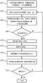
FIG. 2 is a flowchart showing a method for fusing images while compensating for motion in accordance with an illustrative embodiment;
FIG. 3 is a diagram showing a field of view for a baseline and a current pose for determining success parameters in accordance with an illustrative embodiment; and is
Fig. 4 is a flowchart illustrating a method for fusing images while compensating for motion according to another illustrative embodiment.
Detailed Description
In accordance with the present principles, systems, methods, and interfaces, feedback is provided to an operator regarding the success parameters of a current view, and guidance can be provided to the user to achieve the view with the best success parameters. The success parameter is a parameter related to the overlap or similarity between the images to be registered (field of view (FOV)). Without motion compensation, fusion imaging becomes less accurate and less useful when organ motion occurs. Manual motion compensation is cumbersome, inaccurate and user dependent. Automatic image-based motion compensation is fast and accurate only if the live image to be used for registration has sufficient overlap and similarity to the baseline image ("success parameters"). Since the operator's assessment of the success parameters of the ultrasound views is not trivial, the operator can acquire 3DUS (three dimensional ultrasound) images and attempt motion compensation by "trial and error", resulting in failed registration attempts, wasted time, and operator dissatisfaction.
The present principles provide feedback on the success parameters of the current view before acquiring images and performing motion compensation, and provide guidance to views with high or optimal success parameters. The present principles result in efficient motion compensation during multi-modal "fusion" imaging. Image-based registration of a "live" or "current" ultrasound volume relative to a previous "static" ultrasound volume is used to compensate for motion. The static volume may then be pre-registered to another modality, such as a Computed Tomography (CT) image. Registration-based motion compensation uses live and static images to find sufficient similarity and overlap (success parameters).
In one embodiment, the field of view is compared to identify similar poses for the imaging equipment to achieve sufficient overlap between the baseline and live images (success parameters). The interface provides live feedback on these success parameters to guide the user in acquiring live images, which allows for successful and accurate registration with static images.
In one motion compensated embodiment, an operator acquires live, Electromagnetic (EM) tracked 3D ultrasound (3DUS) images that can be registered with a previously static 3 DUS. Based on the known field of view (FOV) of the EM tracking and the 3DUS, the relative pose and overlap between the current view and the still image can be calculated. This information is provided to the operator to identify views suitable for motion compensation while also being suitable for imaging the desired target region (e.g., tumor). In an alternative embodiment, the operator enters the desired target region, and the system calculates one or several suitable views to image with sufficient overlap and similarity to the static image to allow successful motion compensation. The system may then provide guidance to the operator to place the ultrasound probe in or near the pre-computed pose for the 3DUS acquisition. In other embodiments, the baseline and image similarity to the front view may be employed to find the best field of view match.
It should be understood that the present invention will be described with respect to a medical imaging instrument; however, the teachings of the present invention are much broader and are applicable to any imaging instrument where motion compensation is useful. In some embodiments, the present principles are employed in tracking or analyzing complex biological or mechanical systems. In particular, the present principles apply to internal tracking procedures of biological systems, as well as procedures in all regions of the body (e.g., lungs, gastrointestinal tract, excretory organs, blood vessels, etc.). The elements depicted in the drawings may be implemented in various combinations of hardware and software and provide functions which may be combined in a single element or multiple elements.
The functions of the various elements shown in the figures may be provided through the use of dedicated hardware as well as hardware capable of executing software in association with appropriate software. When provided by a processor, the functions may be provided by a single dedicated processor, by a single shared processor, or by a plurality of individual processors, some of which may be shared. Moreover, explicit use of the term "processor" or "controller" should not be construed to refer exclusively to hardware capable of executing software, and can implicitly include, without limitation, digital signal processor ("DSP") hardware, read-only memory ("ROM") for storing software, random access memory ("RAM"), non-volatile storage, and so forth.
Moreover, all statements herein reciting principles, aspects, and embodiments of the invention, as well as specific examples thereof, are intended to encompass both structural and functional equivalents thereof. Further, it is intended that such equivalents include both currently known equivalents as well as equivalents developed in the future (i.e., elements developed that perform the same function, regardless of structure). Thus, for example, it will be appreciated by those skilled in the art that the block diagrams presented herein represent conceptual views of illustrative system components and/or circuitry embodying the principles of the invention. Similarly, it will be appreciated that flow charts, flow diagrams, and the like represent various processes which may be substantially represented in computer readable storage media and so executed by a computer or processor, whether or not such computer or processor is explicitly shown.
Furthermore, embodiments of the invention can take the form of a computer program product accessible from a computer-usable or computer-readable medium providing program code for use by or in connection with a computer or any instruction execution system. For the purposes of this description, a computer-usable or computer readable medium can be any apparatus that can contain, store, communicate, propagate, or transport the program for use by or in connection with the instruction execution system, apparatus, or device. The medium can be an electronic, magnetic, optical, electromagnetic, infrared, or semiconductor system (or apparatus or device) or a propagation medium. Examples of a computer-readable medium include a semiconductor or solid state memory, magnetic tape, a removable computer diskette, a Random Access Memory (RAM), a read-only memory (ROM), a rigid magnetic disk and an optical disk. Examples of current optical disks include compact disk-read only memory (CD-ROM), compact disk-read/write (CD-R/W), Blu-ray diskTMAnd a DVD.
Reference in the specification to "one embodiment" or "an embodiment" of the present principles, and variations thereof, means that a particular feature, structure, characteristic, and the like described in connection with the embodiment is included in at least one embodiment of the present principles. Thus, the appearances of the phrases "in one embodiment" or "in an embodiment" and any other variations appearing in various places throughout the specification are not necessarily all referring to the same embodiment.
It will be appreciated that the use of at least one of the following "/", "and/or" and "… …" (e.g., in the case of "a/B", "a and/or B" and "at least one of a and B") is intended to encompass: selecting only the first listed item (a), only the second listed item (B), or both items (a and B). As another example, in the case of "A, B and/or C" and "at least one of A, B and C," such phrases are intended to encompass: selecting only the first listed item (a), or only the second listed item (B), or only the third listed item (C), or only the first and second listed items (a and B), or only the first and third listed items (a and C), or only the second and third listed items (B and C), or all three items (a and B and C). This can be extended for as many items as listed, as would be apparent to one of ordinary skill in this and related arts.
It will also be understood that when an element such as, for example, an image region, or an overlay, is referred to as being "on" or "over" another element, it can be directly on the other element or intervening elements may also be present. In contrast, when an element is referred to as being "directly on" or "directly over" another element, there are no intervening elements present. It will also be understood that when an element is referred to as being "connected" or "coupled" to another element, it can be directly connected or coupled to the other element or intervening elements may be present. In contrast, when an element is referred to as being "directly connected to" or "directly coupled to" another element, there are no intervening elements present.
Referring now to the drawings, in which like numerals represent the same or similar elements, and initially to FIG. 1, a system 100 for imaging is illustratively shown in accordance with one embodiment. The system 100 may include a computer or other workstation or console 112 from which the processes are supervised and/or managed and/or from which imaging fusion is performed. The workstation 112 preferably includes one or more processors 114 and memory 116 for storing programs and applications. The memory 116 may store a plurality of modules, unit applications, and/or programs configured to fuse images from the same or different imaging modalities. It should be understood that modules described as being stored in memory 116 may actually include electronic circuits or other hardware components, including connectors, wires, circuit boards, integrated circuit chips, memory devices, etc., in addition to or in place of software.
The memory 116 includes a pose analyzer unit 132, the pose analyzer unit 132 receiving spatial pose tracking information from the baseline 3DUS stored in the tracked baseline memory 124 and from the live/current images 111, which may be stored in the tracked current memory 126 when acquired at the current/live location of the imaging probe 102, to calculate success parameters. The imaging probe 102 may comprise an ultrasound probe for live or real-time imaging of the object 130. The imaging probe 102 is tracked using Electromagnetic (EM) tracking 115, although other tracking techniques may be employed. The gesture analyzer unit 132 passes the information (success parameters) to the display 118 and optionally to the gesture guidance unit 138. The gesture guidance unit 138 may receive user input (target region) via a graphical user interface on the display 118 and/or the interface 120. The pose analyzer unit 132 calculates overlap and similarity (success parameters) for measuring field of view similarity, and the pose guidance unit 138 provides direct information on how to reposition the probe 102 to obtain an optimal field of view for the image. As an example, the gesture analyzer unit 132 may provide a percentage of overlap (e.g., 55% overlap) as feedback, while the gesture guidance unit 138 may provide instructions, such as "move probe left", to achieve a higher percentage of overlap.
Live feedback and/or guidance is provided to the user to achieve an optimal pose for performing the task, to replicate the baseline image, to increase the probability of good registration with the previous static image, and the like.
The display 118 may also allow a user to interact with the workstation 112 and its components and functions or any other elements within the system 100. This is further facilitated by the interface 120, which may include a keyboard, mouse, joystick, haptic device, microphone, speaker, light or other peripherals or controls to allow user feedback from the workstation and interaction with the workstation 112. The interface 120 may provide feedback and guidance that is displayed to the operator, and thus is visible on the system's display 118, audible if audio feedback is employed, vibratory if tactile feedback is employed, and so forth.
The system 100 provides an ultrasound fusion imaging system based on spatial tracking of the ultrasound probe 102 (e.g., EM tracking using EM tracking device 140 and EM probe tracking 115). It should be understood that other tracking techniques, such as optical shape sensing, etc., may also be employed. A registration unit 134 (e.g., a multi-modality registration module) provides registration to or to previous static images stored in the memory 122 for different modalities. The prior static image 122 may be captured by any imaging modality 108 (such as, for example, CT, magnetic resonance, X-ray, US, etc.). The imaging modality 108 may be present during the procedure or may provide a still image 122 from a previous procedure or captured image. The registration unit 134 registers the previous still image from the memory 122 with the acquired spatially tracked baseline 3DUS volume stored in the memory 124.
Information from live probe tracking 115 and the known field of view of ultrasound images 111 from live imaging modality 110 is employed to continuously calculate and display the overlap and pose similarity (e.g., provide relative rotation of success parameters, etc.) of the current view with the baseline 3DU stored in memory 124 before a new image 3DUS 126 is acquired, stored, and/or used for registration.
The success parameter may also measure image similarity (e.g., image contrast, brightness, information content, or other features) extracted from the live image. Note that image-based success parameters (from live images) require acquisition and processing of 2D or preliminary images (111) (e.g., live and/or baseline images), while other success parameters only require pose tracking information (and knowledge of the ultrasound field of view-but not the images).
Although US is described, other imaging modalities may be used as the imaging modality 110. Note that the smaller the overlap, the greater the relative rotation between the images, the less likely the image registration is to be successful. The motion compensation unit 128 takes into account motion between the new image 3DUS 126 and the baseline 3DUS image 124 and provides motion compensation information to the registration unit 136, which is used to register the EM coordinate system of the EM tracker 140 with the static image 122 and to provide registration for registering the baseline image 124 to the static image 122 from the registration unit 134.
The motion compensated registration unit 128 calculates the image difference between the baseline image 124 and the tracked current image 126. The pose analyzer unit 132 uses this information to calculate the success parameters for the current pose prior to acquiring a new image. It should be understood that although the registration units and modules are described separately, registration of the various coordinate systems, calculation of the transformations, and other registration functions may be performed by a single or multiple registration units, engines, or programs.
In an alternative embodiment, the system 100 also uses the post-guidance unit 138 to calculate and provide guidance to acquire the best view. The calculation of the optimal view may be used for imaging of, for example, a tumor using operator input of the desired target region to find a view to image the tumor while maintaining sufficient success parameters for motion compensation.
The system 100 can operate on a tracking-based ultrasound fusion imaging system, such as
 Product, the principles of the invention may be applied to other devices and may include other imaging modalities. In a particularly useful embodiment, the present principles can operate on a system that acquires a 3D us baseline image 124, which 3D baseline image 124 is then registered by the registration unit 134 to a previous static image (e.g., CT)122 to be fused with the live ultrasound image 126. It is an object to provide an efficient workflow and method for compensating for organ motion that may occur after the time of capture from the 3DUS baseline image 124. During fusion imaging, the ultrasound system is typically in "live 2D" mode, and the live 2D images 111 from the ultrasound scanner (via the current registration units 134, 136)Fused with the previous still image (CT) 122.
The operator is interested in fusion imaging of a particular target region, such as a tumor, and will move the ultrasound probe 102 to explore the different ways to visualize the tumor. Different views of the tumor are possible, but only some may have sufficient overlap and pose similarity (success parameters) with the baseline 3DUS 124 for motion compensation.
The system 100 continuously calculates and displays success parameters so that the operator can identify a view of the tumor with sufficient success parameters. The operator optionally proceeds to obtain a breath hold of the patient, acquiring a live 2D/3DUS image 111 of the tumor, which is stored in the current view memory 126 once acquired. The motion compensation unit 128 is triggered by acquiring a new 3DUS image (stored in memory 126).
The system 100 performs motion compensation by registering the live 3DUS image 126 with the baseline 3DUS 124 and updating the displayed fused image using the registration result of the registration unit 134. The updated fused image can now be used by the operator to visualize the tumor or to perform an intervention (e.g. needle insertion).
Referring to fig. 2, a method for tracking-based ultrasound fusion imaging is schematically illustrated. In block 202, the fusion imaging system is initialized. The baseline image is acquired and its pose is stored. The acquired image is registered with a previous image (e.g., a static image of the same volume). In particular, an acquisition of a 3DUS baseline image is obtained, which is then registered to a previous static image (e.g., CT) to be fused with live ultrasound. In block 204, a live image of the target zone is obtained. The live image may be, for example, a 2D or 3DUS image. The ultrasound system is typically in "live 2D" mode, and the live 2D image from the ultrasound scanner is fused (via current registration) with the existing static image (CT).
In block 206, the live tracking information (e.g., EM pose and/or image features) and the baseline pose and/or image are employed to calculate and display success parameters. Optionally, the live 2D image from block 204 may also be used to calculate success parameters. Features of the live 2D image, such as image brightness, contrast, etc., may be employed to detect good imaging conditions for successful motion compensation. It is an object to provide an efficient workflow and method for compensating organ motion that may have occurred since the time of a 3DUS baseline image. The system continuously calculates and displays success parameters so that the operator can identify a view of the tumor with sufficient success parameters.
In block 208, a determination of the quality of the success parameter is performed. If the success parameter is sufficient, the path continues to block 210. Otherwise, the path returns to block 204. The operator is interested by imaging the fusion of a specific target region, such as a tumor, and will move the ultrasound probe to explore the different ways of visualizing the tumor. Different views of the tumor are possible, but only some may have sufficient overlap and pose similarity (success parameters) to the baseline 3DUS for motion compensation.
In block 210, the patient may optionally be requested for breath hold. In block 212, acquisition of a new image (e.g., 3DUS) is triggered. This is done when the success parameter is sufficient. In block 214, the newly acquired image (e.g., 3DUS) is registered onto the baseline image. The operator may continue to acquire live 3DUS of the tumor in the current view from obtaining the patient's breath hold, and trigger motion compensation with the acquired 3 DUS.
In block 216, the registration result from block 214 is used to update the registration with the previous US image (baseline or previously acquired US image). The system performs motion compensation by registering the live 3DUS with the baseline 3DUS and updates the fused image using the registration result. In block 218, a determination of fusion quality is made. If the quality is good, the path ends and the updated fused image can now be used by the operator to visualize the tumor or to perform an intervention (e.g. needle insertion). Otherwise, the path returns to block 204 to retry updating the fused image.
Referring to fig. 3, a diagram illustrates ultrasound imaging overlap to describe the calculation of success parameters in the pose analyzer unit 132 of fig. 1. Image overlap and relative pose may be calculated as success parameters (shown in 2D in fig. 3 for simplicity). The ultrasound probes 312, 314 are each positioned to be respectivelyDifferent views 302 and 304 are provided. Pose using baseline 3DUS (transformation: T)US2EM_base(US-to-EM registration for baseline images)) (view 302) and pose of the current 3DUS view (transform: t isUS2EM_current(US-to-EM registration for current image)) (view 304), a relative pose transformation T between the two views 302 and 304 is computedcurrent2base(current-to-baseline image fusion) ═ inv (T)US2EM_base)·TUS2EM_current. In this example, view 302 includes a baseline 3DUS pose, and view 304 includes a current 3DUS pose. The known ultrasound field of view (FOV) (sector images 306 and/or 308) is used to calculate the overlap of the shadow image region 310. Transforming T according to relative attitudecurrent2baseThe image angle difference, α, is calculated directly. The success parameters may include an angle (α) and a shaded area 310. If the angle α is 0 and the shaded area 310 coincides with the views 302, 304, there is no motion to be compensated. Success parameters may also include parameters extracted from 2D US images acquired in different views, such as brightness, contrast, or other image features.
Referring again to fig. 1 and with continued reference to fig. 3, the system 100 may provide feedback and guidance for optimizing the success parameters of the ultrasound view. To this end, the pose analyzer unit 132 will be connected to a pose guidance unit 138 to calculate the ultrasound probe motion required to increase or optimize the parameters. This information is transmitted to the display 118 to show instructions to the operator (e.g., "move left", "rotate clockwise"). The pose guidance unit 138 may use the previous static image 122 (e.g., CT) and information derived therefrom (e.g., skin surface) to determine an acceptable ultrasound pose (e.g., ultrasound probe touching skin).
In another embodiment, the system 100 may provide feedback and guidance to optimize the success parameters of the ultrasound view imaging the user-provided target region. To do so, the interface 120 will allow the operator to enter a 3DUS baseline 124 or target region in a previous static image 122. Information is passed to the pose guidance unit 138 to compute guidance towards the view that imaged the target region while maximizing the success parameters.
The pose analyzer unit 132 can computationally solve the pose optimization problem by considering the probe position and rotation as input parameters to be optimized (possibly limited to the position on the patient's skin as derived from the previous static image 122) and defining a cost function f to be minimized (which is inversely related to the likelihood of success of the motion compensation for the 3DUS acquired at the current pose). One suitable cost function includes:
f_A(pi) 100/percent overlap (p)i)+w*(1-|α(pi) I/90) equation 1
Wherein p isiIs a set of probe translation and rotation parameters { tx, ty, tz, rx, ry, rz } defining the current pose of the probe;
f_A(pi) Is in a posture piAn associated total "cost";
percent overlap (p)i) Is the relative overlap of the regions imaged by the baseline 3DUS and the current 3DUS (e.g., 100x absolute overlap divided by total field of view);
α(pi) Is the angle of rotation between the baseline 3DUS and the current 3DUS in degrees; and is
w is a weighting factor used to balance the relative contributions of the overlap and rotation metrics.
For embodiments using a user-provided target region, the cost function may be modified to reflect the requirements for imaging the target region at the same time. For example,
f_B(pi)=f_A(pi)/T(pi) Equation 2
Wherein, T (p)i) Is a unit step function, 1 if the target zone is completely in the current field of view, otherwise very small (e.g., 1e-10), such that f _ B (p)i) The "cost" in (1) becomes very large.
Using one or more cost functions, the user may move the US probe and be given audio, visual, tactile, etc. feedback from the display 118 or from the interface 120 as the target region is approached to guide the operator to an optimal pose for motion compensation. The cost function may be configured to evaluate the overlap and/or rotation between different image fields of view and image parameters for determining image similarity, e.g. from 2D/preliminary and/or baseline images. The pose guidance unit 138 may also employ one or more cost functions for optimal pose and image similarity to provide guidance commands to the user.
Referring to fig. 4, a method for fusing images to account for motion compensation is illustratively shown in accordance with the present principles. In block 402, a baseline image is captured. In block 404, a live image of the target region is obtained. The live image may be a 2D image or provide a preliminary image. In block 406, the imaging instrument is tracked to obtain a pose for the captured baseline image and to obtain a pose for the current view of the current image such that the tracking system has a coordinate system registered with the baseline image and the live image. In block 408, the pose of the current view is analyzed to compare the field of view difference between the pose for the baseline image and the pose of the current view using the tracking system to generate success parameters. In addition, parameters/image features from live and baseline images may also be calculated and compared. In block 410, success parameters are passed to provide feedback for optimal image acquisition for motion compensation between the baseline image and the current view image. The success parameter measures field of view overlap and pose similarity between the baseline image and the current view image. Success parameters may include different parameters for achieving overlap, pose similarity, and image similarity, such as angle, position, area, percentage, image contrast, brightness, or other quantities or features.
In block 412, if the success parameter is sufficient, a new image is acquired with the pose of the current view. This may be a complete 3D image instead of a 2D image or a preliminary image. The sufficiency of the success parameter may be determined by a user or may be set automatically or as a default value. Determining whether a pose provides a field of view for a current pose comparable to a field of view of a pose of the baseline image to allow a user to replicate the baseline image field of view. For example, a threshold between the baseline field of view and the current field of view, i.e., 90% overlap, for example, may be set to determine sufficiency. Other criteria are also contemplated.
In block 414, the baseline image may be registered with the current view image. In block 416, the static image (e.g., CT, MRI, etc.) may be registered with one or more of the baseline image and the current image(s). This registration may occur at any time, and preferably during an early stage (e.g., planning) with respect to the baseline image being registered to the static image.
In block 418, directions are provided to the user using the pose guidance unit to achieve a satisfactory pose for the current view image. The pose guidance unit may comprise and calculate a cost function to assess overlap between different image fields of view. The cost function may also take into account image parameters, for example, between the live image (e.g., the preliminary 2D image) and the baseline image. The image parameters may include contrast, brightness, content information, and the like.
In block 420, the user action is guided through feedback activity to achieve a satisfactory pose for the current view image. The feedback activity can include at least one of a visual signal (e.g., flashing, image), a text command, an audio signal (e.g., beep, voice command), a tactile signal (e.g., vibration intensity, vibration change), and the like.
In interpreting the appended claims, it should be understood that:
a) the word "comprising" does not exclude the presence of elements or acts other than those listed in a given claim;
b) the word "a" or "an" preceding an element does not exclude the presence of a plurality of such elements;
c) any reference signs in the claims do not limit their scope;
d) several "units" may be represented by the same item or hardware or software implemented structure or function; and is
e) No particular order to certain actions is intended to be required unless specifically indicated.
Having described preferred embodiments for a system and method for image compensation in a medical procedure (which are intended to be illustrative and not limiting), it is noted that modifications and variations can be made by persons skilled in the art in light of the above teachings. It is therefore to be understood that changes may be made in the particular embodiments of the disclosure disclosed which are within the scope of the embodiments disclosed which are defined by the appended claims. Having thus described the details and particularity required by the patent laws, what is claimed or desired protected by letters patent is set forth in the appended claims.
Claims (16)
1. A system for fusing images to account for motion compensation, comprising:
an imaging modality (110) configured to obtain a baseline image and a current image;
a live tracking system (115) configured to track an imaging instrument to obtain a pose for capturing the baseline image and a pose for capturing a current view of the current image, the live tracking system having a coordinate system registered with the baseline image and the current image; and
a pose analysis unit (132) configured to use the live tracking system to generate and deliver as feedback to a user a success parameter based on a field of view difference compared between a pose used to capture the baseline image and a pose used to capture the current view, the success parameter assisting image acquisition for motion compensation between the baseline image and the current view image.
2. The system as recited in claim 1, wherein the pose analysis unit (132) is further configured to generate the success parameters as a measure of overlap and pose similarity between the baseline image and the current view image.
3. The system as recited in claim 1, wherein the pose analysis unit (132) is further configured to generate the success parameter as a measure of image similarity between the baseline image and a live image taken at a current pose.
4. The system as recited in claim 1, wherein the pose analysis unit (132) determines whether a pose for capturing the current view provides a field of view similar to a field of view of a pose for capturing the baseline image to allow a user to replicate the baseline image field of view.
5. The system as recited in claim 1, further comprising a pose guidance unit (138) configured to provide direction information to a user indicating a direction to move the imaging instrument to achieve a desired pose for the current view image.
6. The system as recited in claim 5, wherein the pose guidance unit (138) includes a cost function configured to evaluate overlap and/or rotation between different image fields of view and/or image parameters between the baseline image and the current view image.
7. The system as recited in claim 1, further comprising an interface (120) configured to guide user actions through feedback activities to achieve a desired pose for the current view image.
8. The system of claim 7, wherein the feedback activity includes at least one of a visual signal, a text command, an audio signal, and a haptic signal to guide the user action to the desired gesture.
9. A method for fusing images to account for motion compensation, comprising:
capturing a baseline image;
acquiring a live image of a target area;
tracking an imaging instrument to obtain a pose for capturing the baseline image and to obtain a pose for capturing a current view of the live image such that a coordinate system of a tracking system is registered with the baseline image and the live image;
analyzing a pose for a current view to compare a field of view difference between the pose for the baseline image and the pose for the current view using the tracking system to generate a success parameter;
communicating the success parameter to provide feedback on image acquisition for motion compensation between the baseline image and the current view; and is
If the success parameter is sufficient, a new image is acquired with the pose of the current view.
10. The method of claim 9, wherein the success parameters measure overlap and pose similarity between the baseline image and the current view.
11. The method of claim 9, wherein the success parameter measures image similarity between the baseline image and a live image taken at the pose of the current view.
12. The method of claim 9, further comprising determining whether the pose used to capture the current view provides a field of view comparable to the field of view used to capture the pose of the baseline image to allow a user to replicate the baseline image field of view.
13. The method of claim 9, further comprising providing directional information to a user to achieve a desired pose for the current view using a pose guidance unit.
14. The method according to claim 13, wherein the pose guidance unit comprises a cost function configured to evaluate overlap between different image fields of view and/or image parameters between the baseline image and live images.
15. The method of claim 9, further comprising guiding user actions to achieve a desired pose for the current view image through feedback activities, wherein the feedback activities include at least one of visual signals, text commands, audio signals, and tactile signals.
16. A computer readable medium having stored thereon instructions adapted to perform the method of any one of claims 9-15 when executed.
Applications Claiming Priority (3)
| Application Number | Priority Date | Filing Date | Title |
|---|---|---|---|
| US201562158011P | 2015-05-07 | 2015-05-07 | |
| US62/158,011 | 2015-05-07 | ||
| PCT/IB2016/052623 WO2016178198A1 (en) | 2015-05-07 | 2016-05-09 | System and method for motion compensation in medical procedures |
Publications (2)
| Publication Number | Publication Date |
|---|---|
| CN107980148A CN107980148A (en) | 2018-05-01 |
| CN107980148B true CN107980148B (en) | 2022-06-28 |
Family
ID=56072372
Family Applications (1)
| Application Number | Title | Priority Date | Filing Date |
|---|---|---|---|
| CN201680026452.4A Active CN107980148B (en) | 2015-05-07 | 2016-05-09 | System and method for fusing images to account for motion compensation |
Country Status (5)
| Country | Link |
|---|---|
| US (1) | US10893851B2 (en) |
| EP (1) | EP3291735A1 (en) |
| JP (1) | JP6714019B2 (en) |
| CN (1) | CN107980148B (en) |
| WO (1) | WO2016178198A1 (en) |
Families Citing this family (14)
| Publication number | Priority date | Publication date | Assignee | Title |
|---|---|---|---|---|
| WO2016175758A2 (en) | 2015-04-28 | 2016-11-03 | Analogic Corporation | Image guided steering of a transducer array and/or an instrument |
| JP6714019B2 (en) * | 2015-05-07 | 2020-06-24 | コーニンクレッカ フィリップス エヌ ヴェKoninklijke Philips N.V. | System and method for motion compensation in medical procedures |
| RU2769065C2 (en) * | 2017-05-11 | 2022-03-28 | Конинклейке Филипс Н.В. | Technological process, system and method of motion compensation during ultrasonic procedures |
| US20200275915A1 (en) * | 2017-09-08 | 2020-09-03 | Koninklijke Philips N.V. | Ultrasound probe localization with drift correction |
| EP3482690A1 (en) * | 2017-11-14 | 2019-05-15 | Koninklijke Philips N.V. | Ultrasound tracking and visualization |
| CN111587449A (en) | 2017-12-04 | 2020-08-25 | 皇家飞利浦有限公司 | Image data processing method, device and system |
| EP4218596A1 (en) * | 2018-05-15 | 2023-08-02 | New York University | System and method for orientating capture of ultrasound images |
| CN111292277B (en) * | 2018-12-10 | 2021-02-09 | 深圳迈瑞生物医疗电子股份有限公司 | Ultrasonic fusion imaging method and ultrasonic fusion imaging navigation system |
| KR20200109467A (en) * | 2019-03-13 | 2020-09-23 | 삼성전자주식회사 | Electric apparatus and method for control thereof |
| NL2023588B1 (en) * | 2019-07-29 | 2021-02-18 | Elitac | Vibrotactile feedback arrangement |
| US20210045716A1 (en) * | 2019-08-13 | 2021-02-18 | GE Precision Healthcare LLC | Method and system for providing interaction with a visual artificial intelligence ultrasound image segmentation module |
| US11607200B2 (en) * | 2019-08-13 | 2023-03-21 | GE Precision Healthcare LLC | Methods and system for camera-aided ultrasound scan setup and control |
| CN112130134B (en) * | 2020-08-17 | 2023-12-05 | 河北汉光重工有限责任公司 | Real-time baseline correction method based on time compensation |
| US20230172585A1 (en) * | 2021-12-03 | 2023-06-08 | GE Precision Healthcare LLC | Methods and systems for live image acquisition |
Family Cites Families (42)
| Publication number | Priority date | Publication date | Assignee | Title |
|---|---|---|---|---|
| US7127090B2 (en) * | 2001-07-30 | 2006-10-24 | Accuimage Diagnostics Corp | Methods and systems for combining a plurality of radiographic images |
| DE10149795B4 (en) * | 2001-10-09 | 2006-04-06 | Siemens Ag | Semiautomatic registration for overlaying two medical image data sets |
| JP4088104B2 (en) * | 2002-06-12 | 2008-05-21 | 株式会社東芝 | Ultrasonic diagnostic equipment |
| JP4705104B2 (en) * | 2004-08-09 | 2011-06-22 | ブラッコ・シュイス・ソシエテ・アノニム | Image registration method and apparatus for medical image processing based on multiple masks |
| US20060093192A1 (en) * | 2004-11-03 | 2006-05-04 | Bechtel J S | Finger guide device |
| JP4470187B2 (en) * | 2004-12-03 | 2010-06-02 | 株式会社日立メディコ | Ultrasonic device, ultrasonic imaging program, and ultrasonic imaging method |
| US7813591B2 (en) * | 2006-01-20 | 2010-10-12 | 3M Innovative Properties Company | Visual feedback of 3D scan parameters |
| US20080186378A1 (en) * | 2007-02-06 | 2008-08-07 | Feimo Shen | Method and apparatus for guiding towards targets during motion |
| US9597041B2 (en) * | 2007-03-30 | 2017-03-21 | General Electric Company | Sequential image acquisition with updating method and system |
| CN101053531A (en) * | 2007-05-17 | 2007-10-17 | 上海交通大学 | Early tumor positioning and tracking method based on multi-mold sensitivity intensifying and imaging fusion |
| RU2468435C2 (en) * | 2007-11-14 | 2012-11-27 | Конинклейке Филипс Электроникс, Н.В. | System and method for quantitative 3d ceus imaging |
| US9651662B2 (en) * | 2007-11-16 | 2017-05-16 | Koninklijke Philips N.V. | Interventional navigation using 3D contrast-enhanced ultrasound |
| EP2231277B1 (en) * | 2007-12-23 | 2017-08-30 | Carl Zeiss Meditec, Inc. | Devices for detecting, controlling, and predicting radiation delivery |
| US7801271B2 (en) * | 2007-12-23 | 2010-09-21 | Oraya Therapeutics, Inc. | Methods and devices for orthovoltage ocular radiotherapy and treatment planning |
| JP2009200713A (en) * | 2008-02-20 | 2009-09-03 | Sony Corp | Image processing device, image processing method, and program |
| WO2010037436A1 (en) | 2008-09-30 | 2010-04-08 | Mediri Gmbh | 3d motion detection and correction by object tracking in ultrasound images |
| EP2210844B1 (en) * | 2009-01-26 | 2012-04-04 | Neopost Technologies | Method and apparatus for feeding and folding sheets |
| US9412044B2 (en) * | 2009-06-09 | 2016-08-09 | Siemens Aktiengesellschaft | Method of compensation of respiratory motion in cardiac imaging |
| DE102010009295B4 (en) * | 2010-02-25 | 2019-02-21 | Siemens Healthcare Gmbh | Method for displaying a region to be examined and / or treated |
| CA2797302C (en) * | 2010-04-28 | 2019-01-15 | Ryerson University | System and methods for intraoperative guidance feedback |
| US20140194793A1 (en) * | 2010-05-14 | 2014-07-10 | Kai Medical, Inc. | Systems and methods for non-contact multiparameter vital signs monitoring, apnea therapy, apnea diagnosis, and snore therapy |
| WO2011143631A2 (en) * | 2010-05-14 | 2011-11-17 | Kai Medical, Inc. | Systems and methods for non-contact multiparameter vital signs monitoring, apnea therapy, sway cancellation, patient identification, and subject monitoring sensors |
| CN102970926B (en) * | 2010-06-28 | 2016-08-17 | 皇家飞利浦电子股份有限公司 | The real-time quality of EM calibration controls |
| EP2680778B1 (en) * | 2011-03-03 | 2019-07-31 | Koninklijke Philips N.V. | System and method for automated initialization and registration of navigation system |
| US8810640B2 (en) * | 2011-05-16 | 2014-08-19 | Ut-Battelle, Llc | Intrinsic feature-based pose measurement for imaging motion compensation |
| JP2011205681A (en) * | 2011-05-27 | 2011-10-13 | Hitachi Ltd | Recording method |
| US8588501B2 (en) * | 2011-07-29 | 2013-11-19 | Siemens Aktiengesellschaft | Automatic pose initialization for accurate 2-D/3-D registration applied to abdominal aortic aneurysm endovascular repair |
| KR20140049137A (en) * | 2012-10-12 | 2014-04-25 | 삼성전자주식회사 | Medical image analyzing apparatus and method |
| US9001226B1 (en) * | 2012-12-04 | 2015-04-07 | Lytro, Inc. | Capturing and relighting images using multiple devices |
| WO2014110069A1 (en) * | 2013-01-11 | 2014-07-17 | The Cleveland Clinic Foundation | Alignment of manipulable sensor assembly |
| US9131922B2 (en) * | 2013-01-29 | 2015-09-15 | Eigen, Inc. | Calibration for 3D reconstruction of medical images from a sequence of 2D images |
| EP2973417B1 (en) * | 2013-03-11 | 2020-07-15 | Carestream Dental Technology Topco Limited | A method and system for three-dimensional imaging |
| US10278584B2 (en) * | 2013-03-11 | 2019-05-07 | Carestream Dental Technology Topco Limited | Method and system for three-dimensional imaging |
| TR201807210T4 (en) * | 2013-11-06 | 2018-06-21 | Koninklijke Philips Nv | A system and method for guiding a user during a shaving procedure. |
| US10068373B2 (en) * | 2014-07-01 | 2018-09-04 | Samsung Electronics Co., Ltd. | Electronic device for providing map information |
| US20160106381A1 (en) * | 2014-10-20 | 2016-04-21 | General Electric Company | Ultrasound probe with tactile indicator |
| US9626589B1 (en) * | 2015-01-19 | 2017-04-18 | Ricoh Co., Ltd. | Preview image acquisition user interface for linear panoramic image stitching |
| JP6436442B2 (en) * | 2015-04-10 | 2018-12-12 | キヤノン株式会社 | Photoacoustic apparatus and image processing method |
| JP6714019B2 (en) * | 2015-05-07 | 2020-06-24 | コーニンクレッカ フィリップス エヌ ヴェKoninklijke Philips N.V. | System and method for motion compensation in medical procedures |
| US10646199B2 (en) * | 2015-10-19 | 2020-05-12 | Clarius Mobile Health Corp. | Systems and methods for remote graphical feedback of ultrasound scanning technique |
| US10964424B2 (en) * | 2016-03-09 | 2021-03-30 | EchoNous, Inc. | Ultrasound image recognition systems and methods utilizing an artificial intelligence network |
| EP3574504A1 (en) * | 2017-01-24 | 2019-12-04 | Tietronix Software, Inc. | System and method for three-dimensional augmented reality guidance for use of medical equipment |
-
2016
- 2016-05-09 JP JP2017557317A patent/JP6714019B2/en active Active
- 2016-05-09 CN CN201680026452.4A patent/CN107980148B/en active Active
- 2016-05-09 US US15/567,648 patent/US10893851B2/en active Active
- 2016-05-09 WO PCT/IB2016/052623 patent/WO2016178198A1/en active Application Filing
- 2016-05-09 EP EP16724717.0A patent/EP3291735A1/en active Pending
Also Published As
| Publication number | Publication date |
|---|---|
| US20180146955A1 (en) | 2018-05-31 |
| EP3291735A1 (en) | 2018-03-14 |
| WO2016178198A1 (en) | 2016-11-10 |
| JP6714019B2 (en) | 2020-06-24 |
| CN107980148A (en) | 2018-05-01 |
| JP2018518226A (en) | 2018-07-12 |
| US10893851B2 (en) | 2021-01-19 |
Similar Documents
| Publication | Publication Date | Title |
|---|---|---|
| CN107980148B (en) | System and method for fusing images to account for motion compensation | |
| KR102013866B1 (en) | Method and apparatus for calculating camera location using surgical video | |
| US9978141B2 (en) | System and method for fused image based navigation with late marker placement | |
| US9687204B2 (en) | Method and system for registration of ultrasound and physiological models to X-ray fluoroscopic images | |
| US9665936B2 (en) | Systems and methods for see-through views of patients | |
| US10762380B2 (en) | Registration system for registering an imaging device with a tracking device | |
| US10977787B2 (en) | Feedback for multi-modality auto-registration | |
| US10424067B2 (en) | Image processing apparatus, image processing method and storage medium | |
| RU2711140C2 (en) | Editing medical images | |
| US10796498B2 (en) | Image processing apparatus, image processing method, and non-transitory computer-readable medium | |
| JP6541363B2 (en) | Image processing apparatus, image processing method and program | |
| EP3463097B1 (en) | Correcting probe induced deformation in an ultrasound fusing imaging system | |
| US9588666B2 (en) | Image processing apparatus, image processing method, and storage medium | |
| US10786309B2 (en) | Radiation-free registration of an optical shape sensing system to an imaging system | |
| JP2015529478A (en) | Overlay and registration of preoperative data on live video using portable devices | |
| US8588490B2 (en) | Image-based diagnosis assistance apparatus, its operation method and program | |
| US10699424B2 (en) | Image processing apparatus, image processing method, and non-transitory computer readable medium with generation of deformed images | |
| CN105030265A (en) | Image display apparatus, image display method and storage medium storing image display program | |
| US20230298186A1 (en) | Combining angiographic information with fluoroscopic images | |
| Banerjee | Fast 4D Ultrasound Registration for Image Guided Liver Interventions | |
| CN116763401A (en) | Puncture path planning system, method and surgical robot |
Legal Events
| Date | Code | Title | Description |
|---|---|---|---|
| PB01 | Publication | ||
| PB01 | Publication | ||
| SE01 | Entry into force of request for substantive examination | ||
| SE01 | Entry into force of request for substantive examination | ||
| GR01 | Patent grant | ||
| GR01 | Patent grant |