CN107834689B - System and method for emergency lighting - Google Patents
System and method for emergency lighting Download PDFInfo
- Publication number
- CN107834689B CN107834689B CN201711328574.1A CN201711328574A CN107834689B CN 107834689 B CN107834689 B CN 107834689B CN 201711328574 A CN201711328574 A CN 201711328574A CN 107834689 B CN107834689 B CN 107834689B
- Authority
- CN
- China
- Prior art keywords
- lighting unit
- state
- power
- tactile switch
- mains
- Prior art date
- Legal status (The legal status is an assumption and is not a legal conclusion. Google has not performed a legal analysis and makes no representation as to the accuracy of the status listed.)
- Active
Links
Images


Classifications
-
- H—ELECTRICITY
- H02—GENERATION; CONVERSION OR DISTRIBUTION OF ELECTRIC POWER
- H02J—CIRCUIT ARRANGEMENTS OR SYSTEMS FOR SUPPLYING OR DISTRIBUTING ELECTRIC POWER; SYSTEMS FOR STORING ELECTRIC ENERGY
- H02J9/00—Circuit arrangements for emergency or stand-by power supply, e.g. for emergency lighting
- H02J9/02—Circuit arrangements for emergency or stand-by power supply, e.g. for emergency lighting in which an auxiliary distribution system and its associated lamps are brought into service
-
- H—ELECTRICITY
- H02—GENERATION; CONVERSION OR DISTRIBUTION OF ELECTRIC POWER
- H02J—CIRCUIT ARRANGEMENTS OR SYSTEMS FOR SUPPLYING OR DISTRIBUTING ELECTRIC POWER; SYSTEMS FOR STORING ELECTRIC ENERGY
- H02J9/00—Circuit arrangements for emergency or stand-by power supply, e.g. for emergency lighting
- H02J9/04—Circuit arrangements for emergency or stand-by power supply, e.g. for emergency lighting in which the distribution system is disconnected from the normal source and connected to a standby source
- H02J9/06—Circuit arrangements for emergency or stand-by power supply, e.g. for emergency lighting in which the distribution system is disconnected from the normal source and connected to a standby source with automatic change-over, e.g. UPS systems
- H02J9/061—Circuit arrangements for emergency or stand-by power supply, e.g. for emergency lighting in which the distribution system is disconnected from the normal source and connected to a standby source with automatic change-over, e.g. UPS systems for DC powered loads
-
- H—ELECTRICITY
- H02—GENERATION; CONVERSION OR DISTRIBUTION OF ELECTRIC POWER
- H02J—CIRCUIT ARRANGEMENTS OR SYSTEMS FOR SUPPLYING OR DISTRIBUTING ELECTRIC POWER; SYSTEMS FOR STORING ELECTRIC ENERGY
- H02J9/00—Circuit arrangements for emergency or stand-by power supply, e.g. for emergency lighting
- H02J9/04—Circuit arrangements for emergency or stand-by power supply, e.g. for emergency lighting in which the distribution system is disconnected from the normal source and connected to a standby source
- H02J9/06—Circuit arrangements for emergency or stand-by power supply, e.g. for emergency lighting in which the distribution system is disconnected from the normal source and connected to a standby source with automatic change-over, e.g. UPS systems
- H02J9/062—Circuit arrangements for emergency or stand-by power supply, e.g. for emergency lighting in which the distribution system is disconnected from the normal source and connected to a standby source with automatic change-over, e.g. UPS systems for AC powered loads
- H02J9/065—Circuit arrangements for emergency or stand-by power supply, e.g. for emergency lighting in which the distribution system is disconnected from the normal source and connected to a standby source with automatic change-over, e.g. UPS systems for AC powered loads for lighting purposes
-
- H—ELECTRICITY
- H05—ELECTRIC TECHNIQUES NOT OTHERWISE PROVIDED FOR
- H05B—ELECTRIC HEATING; ELECTRIC LIGHT SOURCES NOT OTHERWISE PROVIDED FOR; CIRCUIT ARRANGEMENTS FOR ELECTRIC LIGHT SOURCES, IN GENERAL
- H05B47/00—Circuit arrangements for operating light sources in general, i.e. where the type of light source is not relevant
- H05B47/10—Controlling the light source
- H05B47/105—Controlling the light source in response to determined parameters
- H05B47/11—Controlling the light source in response to determined parameters by determining the brightness or colour temperature of ambient light
-
- H—ELECTRICITY
- H05—ELECTRIC TECHNIQUES NOT OTHERWISE PROVIDED FOR
- H05B—ELECTRIC HEATING; ELECTRIC LIGHT SOURCES NOT OTHERWISE PROVIDED FOR; CIRCUIT ARRANGEMENTS FOR ELECTRIC LIGHT SOURCES, IN GENERAL
- H05B47/00—Circuit arrangements for operating light sources in general, i.e. where the type of light source is not relevant
- H05B47/10—Controlling the light source
- H05B47/105—Controlling the light source in response to determined parameters
- H05B47/115—Controlling the light source in response to determined parameters by determining the presence or movement of objects or living beings
-
- H—ELECTRICITY
- H05—ELECTRIC TECHNIQUES NOT OTHERWISE PROVIDED FOR
- H05B—ELECTRIC HEATING; ELECTRIC LIGHT SOURCES NOT OTHERWISE PROVIDED FOR; CIRCUIT ARRANGEMENTS FOR ELECTRIC LIGHT SOURCES, IN GENERAL
- H05B47/00—Circuit arrangements for operating light sources in general, i.e. where the type of light source is not relevant
- H05B47/10—Controlling the light source
- H05B47/175—Controlling the light source by remote control
- H05B47/185—Controlling the light source by remote control via power line carrier transmission
-
- H—ELECTRICITY
- H05—ELECTRIC TECHNIQUES NOT OTHERWISE PROVIDED FOR
- H05B—ELECTRIC HEATING; ELECTRIC LIGHT SOURCES NOT OTHERWISE PROVIDED FOR; CIRCUIT ARRANGEMENTS FOR ELECTRIC LIGHT SOURCES, IN GENERAL
- H05B47/00—Circuit arrangements for operating light sources in general, i.e. where the type of light source is not relevant
- H05B47/10—Controlling the light source
-
- Y—GENERAL TAGGING OF NEW TECHNOLOGICAL DEVELOPMENTS; GENERAL TAGGING OF CROSS-SECTIONAL TECHNOLOGIES SPANNING OVER SEVERAL SECTIONS OF THE IPC; TECHNICAL SUBJECTS COVERED BY FORMER USPC CROSS-REFERENCE ART COLLECTIONS [XRACs] AND DIGESTS
- Y02—TECHNOLOGIES OR APPLICATIONS FOR MITIGATION OR ADAPTATION AGAINST CLIMATE CHANGE
- Y02B—CLIMATE CHANGE MITIGATION TECHNOLOGIES RELATED TO BUILDINGS, e.g. HOUSING, HOUSE APPLIANCES OR RELATED END-USER APPLICATIONS
- Y02B20/00—Energy efficient lighting technologies, e.g. halogen lamps or gas discharge lamps
- Y02B20/40—Control techniques providing energy savings, e.g. smart controller or presence detection
Landscapes
- Business, Economics & Management (AREA)
- Emergency Management (AREA)
- Engineering & Computer Science (AREA)
- Power Engineering (AREA)
- Circuit Arrangement For Electric Light Sources In General (AREA)
- Circuit Arrangements For Discharge Lamps (AREA)
Abstract
A lighting network (100) and a plurality of methods are thus disclosed. A lighting network (100) a plurality of lighting units (10) capable of operating on AC power and capable of operating on DC backup power when AC power is removed. The controller (15) is used to redistribute DC power among the plurality of lighting units (10) in the event that the DC power in one of the plurality of lighting units (10) is low or exhausted.
Description
The present invention relates to systems and methods for providing stateful lighting, and more particularly, to a network-based distributed plug-in emergency light system.
In many areas of the world, the power provided by utility companies may be unreliable. In such areas, buildings are often equipped with emergency lighting systems. Emergency lighting systems typically consist of a single (battery-backed) emergency light that is often placed in the living room/lobby of a house. Even if a conventional emergency light is on when a power outage occurs, such a conventional emergency lighting system provides little help if the occupants of the house are not in the single room in which the emergency light is located. This also results in wasted energy when the occupant is not in the room in which the emergency light is located.
In order to illuminate another room, a fully/partially charged battery backup light must be used. This causes inconvenience or safety hazards in emergency situations, as the battery backup light has to be found/moved in the dark. To experience a light backup without trouble, the user has to have multiple lamps with sufficient storage/battery life. This solution is expensive.
Accordingly, there is a need in the art for a system and method that addresses the deficiencies of conventional emergency lighting systems described above.
One aspect of the present invention relates to a network-based distributed plug-in emergency light solution that can provide light backup in multiple rooms or living areas of a building. Unlike conventional emergency lights discussed above, plug-in emergency lights according to embodiments of the present invention may be used as normal lights, have less electrical storage and/or have intelligence to minimize waste of backup energy when the user is not nearby or when daylight is available. A network-based distributed plug-in emergency light may connect a battery power storage system that may be used by all plug-in emergency lights in a building during a power outage. Such power sharing networks help to extend the light availability for a limited period of time in the occupied spaces of a building. In this way, compact low cost lamps in different rooms can be combined to give the user better performance.
In another aspect of the invention, a power sharing network connects all plug-in emergency lights on existing AC lines in a building during a power outage interval, identifies the available storage in each of the plug-in emergency lights, and adjusts the power resources by sending power from one plug-in emergency light to another to extend light availability in the occupied space of the building.
In another embodiment, a power sharing network connects all plug-in emergency lights with additional wiring to form a DC network, identifies the available storage in each of the plug-in emergency lights, and adjusts the power resources by sending power from one plug-in emergency light to another to extend the light availability for a predetermined time in the occupancy space of the building.
In another embodiment of the invention, the proposed invention uses additional lines to exchange power and data between plug-in emergency lamps during power outages and uses a simplified control architecture.
In another embodiment of the invention, additional battery packs may be connected to the DC network to spread the light in one or more of the rooms in the event of an emergency or planned activity. This can be done by reserving a node on the DC network and connecting an additional battery pack to this (idle) reserved node.
In other embodiments of the invention, various types of conventional emergency lights may also be added and networked together with the plug-in emergency light.
In another embodiment of the invention, a grid power monitoring unit is used to communicate with all plug-in emergency lights to configure the network.
In one embodiment, the present invention is directed to a lighting network comprising a plurality of lighting units operable on AC power and on DC power when AC power is removed. The controller is arranged to redistribute the DC power among the plurality of lighting units. The lighting network also has an AC power monitoring unit arranged to detect the presence or absence of AC power. The controller redistributes the DC power in the lighting network using the same distribution path used by the AC power.
In another embodiment, the invention is directed to a lighting unit comprising a lighting emitting unit, a driver coupled to the lighting emitting unit, and an AC/DC converter arranged to supply power to the driver. A DC battery unit (14) is also coupled to the drive and arranged to supply power to the drive when the AC/DC converter is unable to supply power to the drive. The controller (15) is arranged to request additional power when power from the DC battery unit is insufficient. The lighting unit also includes a bypass switch to DC power under control from the controller when AC power is not available.
In yet another embodiment, the lighting unit further comprises a DC input path receiving additional power.
Another embodiment of the present invention is directed to a method for supplying DC backup lighting for an area. The method comprises the following steps: determining whether an AC outage has occurred and determining whether the area was illuminated before the AC outage occurred. Based on these determinations, if the area was not previously illuminated, the area is not supplied with DC backup lighting, and if the area was previously illuminated, the DC backup lighting is supplied when the light source was not previously daylight.
In another embodiment of the invention, the on-off switch of the trusted lighting unit is replaced by a tactile switch. Whenever the user presses the tactile switch, power to the trusted lighting unit is momentarily cut off and the event is registered. Whenever the event is registered, the trusted lighting unit is flipped from an on state to an off state, or vice versa. If the loss of power is not instantaneous, the event is identified as a power outage condition.
In yet another embodiment of the present invention, a control circuit is used to distinguish tactile switch operation from momentary mains voltage dips to avoid false triggers.
In general, the various aspects and embodiments of the invention may be combined and coupled in any way possible within the scope of the invention. The subject matter which is regarded as the invention is particularly pointed out and distinctly claimed in the claims at the conclusion of the specification.
The foregoing and other features and advantages of the invention will be apparent from the following detailed description taken in conjunction with the accompanying drawings.
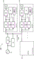
Fig. 1 shows a schematic of a power sharing network for plug-in emergency lamps (or trusted lamps) according to an embodiment of the invention.
Fig. 2 shows a schematic of a power sharing network for a plug-in emergency lamp (or trusted lamp) according to another embodiment of the invention.
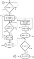
Fig. 3 illustrates a snap shot method according to another embodiment of the invention.
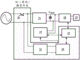
FIG. 4 shows an illustration of a tactile switch feature for a plug-in emergency light according to another embodiment of the invention.
FIG. 5 illustrates a method of operation for a trusted light with tactile switches.
As shown in fig. 1, the network 100 of trusted lights 10 will operate in a normal mode when there is AC power supplied by the AC mains 11. In this normal mode, the trusted lamp 10 operates as a normal stand-alone lamp. When AC power is available, the lamp 10 may be trusted to be in a battery charging or trickle charging mode. A control switch (not shown) may be used to turn the trusted light on or off. The presence of AC power (i.e. grid/mains power) is monitored by the power monitoring unit 12. When AC power is not present, the power monitoring unit 12 sends a signal to the power isolator switch 13 to disconnect the local distribution from the AC mains 11. When AC power is not present, all trusted lights 10 in the network 100 switch to form a DC network for data/power transfer. When AC power is restored, the power monitoring unit 12 sends another signal to all trusted lights 10 to switch to AC power.
The network 100 is disconnected from the AC mains 11 by the power isolator switch 13 and each of the trusted lights 10 is powered by the charge management/battery unit 14. Note that the charge management/battery unit 14 may be two separate components.
In the event that a particular one or more of the trusted lights 10 needs to provide light beyond a specified limited period of time (e.g., some set time or capacity of the battery 14), the user may trigger that particular light via a remote device or a push switch or touch sensor (not shown). The network 100 may also include proximity sensors 20 and/or daylight sensors 21 to optimize power resources to extend light availability. The sensor 20/21 may also be included as part of the lighting driver 18. Accordingly, the trusted light 10 may automatically sense the user and turn on, either instead of or in addition to a trigger from the user, and if needed, draw additional power as described below.
If a particular lamp 10 has a fully discharged battery 14, that particular lamp 10 will search for power availability on the network 100 by sending a power exhaust signal to one or more of the other trusted lamps 10 in the network 100. This is done by the communication controller 15.
The choice of communication may be a PLC or any other conventional device. PLC stands for power line communication or Power Line Carrier (PLC), also known as power line digital subscriber line (PDSL), mains communication, Power Line Telecommunications (PLT), Power Line Networking (PLN) or broadband over power line (BPL), and is a system for carrying data on conductors that are also used for power transmission.
A trusted lamp 10 that receives a power exhaustion signal and has sufficient reserve power in its own battery 14 will send a signal back to the trusted lamp 10 that initiated the request for a power exhaustion signal. Each of the trusted lights 10 has a unique identifiable code that can be addressed. Once the protocol handshake between two or more trusted lamps 10 is completed, the trusted lamp 10 with stored energy will allow the trusted lamp 10 initiating the power drain signal request to access its battery 14.
In order to enable power from the battery 14 to pass from one of the trusted lights 10 to the other over the network 100, the AC/DC converters 16 on both trusted lights 10 are bypassed using the bypass switch 17. The bypass switch 17 remains connected for a predetermined time or may be controlled by the trusted lamp 10 initiating the request for a dry out signal (i.e., the sender lamp 10).
Before connecting power to the lighting driver 18 of the lighting unit 19, the communication controller 15 of the sender lamp 10 will ensure that the lighting unit 19 is not generating light. The lighting unit 19 may be an LED unit or other lighting generating unit. The communication controller 15 will also control the charge management/battery unit 14 so as not to charge the battery 14 of the sender lamp 10 and to use only the received power to supply power to the lighting unit 19 via the lighting driver 18. Other trusted lights 10 in the network 100 will be isolated or in a high impedance mode. In this way, the network 100 operates in a seamless manner to make light available to the user for a predetermined time.
Once AC power is restored, the network 100 will monitor and reconnect the trusted lights 10 in the network 100 to the AC mains 11.
Fig. 2 shows another embodiment of a power sharing network 200 for a plug-in emergency light. The same reference numerals are used for the same or similar elements as those shown in fig. 1. As shown in fig. 2, separate lines are used to share battery power between the trusted lights 10 and from the main power storage unit 22. Separate wires are also used to allow the trusted lamps 10 to communicate with each other. When AC power is available, each of the trusted lights operates independently as a regular light with AC grid power.
In the event of a power outage to the AC power grid, the trusted light 10 may sense the presence of a user in the room and be turned on in accordance with the power associated with the battery 14. When the batteries 14 associated with the individual trusted lamps 10 are depleted, the charge management system 14 will search for power availability on the DC network by sending a power drain signal to each of the other trusted lamps 10 in the network 200. This request and reply process is similar to the protocol described with respect to the embodiment shown in fig. 1. The serial switch in the charge management unit 14 in the trusted lights 10 is used to form a low-impedance network for power to flow from one of the trusted lights 10 to the other. The network 200 may also include a presence/daylight sensor 20/21 to optimize power resources to extend light availability.
In another embodiment, the networks 100 and/or 200 may include a "snapshot" feature that remembers the state of the room at the instant the AC was powered off. The trusted light 10 will only be switched on when the room is in an illuminated state before an AC power outage occurs. Otherwise, the trusted light 10 will not automatically turn on in the event of an AC power outage that occurs when the room was previously in an unlit state. The daylight sensor 21 is used to sense the lighting condition around the moment of AC outage. The daylight sensor 21 should be able to distinguish between daylight and artificial light so that it should not be switched on during the day.
It should be understood that the "snapshot" feature described herein may be used with other types of emergency lights and is not limited to use with only networked trusted lights 10.
A method for implementing a snapshot feature of the on/off of the trusted light 10 based on the room lighting conditions is shown in fig. 3. The method may be embodied as an algorithm or computer readable code accessible or embedded in one of the components of the trusted lamp 10 (e.g. the communication controller 15). The component may be, for example, a microcontroller, an ASIC or a ROM.
In step S1 of fig. 3, it is determined whether an AC power outage has occurred. In step S2, it is checked whether the room is illuminated at the moment the AC is powered off. In step S3, it is determined whether the light source is sunlight. In step S4, it is checked whether the room is currently occupied. In step S5, the trusted light 10 is turned on. In step S6, the trusted light 10 is maintained in an off state. In step S7, it is checked whether there is motion in the room. In step S8, the trusted light is turned on. In step S9, it is determined whether AC power is restored. In step S10, the trusted light 10 is turned off.
Those skilled in the art will appreciate that the flow of the method shown in fig. 3 may be adjusted to cover various variations of turning on/off the trusted light 10 based on the restoration of AC power from the presence sensor 20 and the daylight sensor 21.
In another embodiment, the presence sensor 20 should be able to distinguish between the presence and motion of a user so that the trusted light 10, which was snapshotted dark at the moment of AC power down, is turned on whenever the presence sensor 20 senses motion in the room. Once the presence sensor 20 detects motion in the room, the presence sensor 20 assumes control and turns the trusted light 10 off or on based on the motion detection.
In another embodiment, the trusted light 10 may also include indicators that display various status conditions. For example, the indicator may show the user that the trusted light 10 has sensed a dark condition at the time of the AC power outage and has kept the light in an off condition, e.g., the user may be sleeping in a room.
In another embodiment, one node of the network 200 may be intentionally kept idle in order to extend the availability of light in one or more of the rooms. Whenever a charged battery is connected to the idle node, the idle node will communicate with the main storage unit 22, which main storage unit 22 will cause the shared power to go from the idle node to the requesting trusted lamp 10.
In another embodiment, the trusted light 10 may have a variable light level output to reduce/extend the power standby time. Such dimming may be varied based on a predetermined time or a predetermined battery threshold level.
In another embodiment of the present invention, the conventional on-off switch for controlling the trusted light 10 is replaced by a tactile switch 30. Whenever the user presses the tactile switch 30, power to the trusted light 10 is momentarily cut off and this event is registered. Whenever the event is registered, the trusted light 10 is flipped from the on state to the off state, or vice versa. This means that if the trusted light 10 is in the on condition, it is switched to the off condition, or vice versa. If the trusted light 10 determines that the loss of mains power exceeds a predetermined threshold limit, then the event is identified as a power-off condition and the lighting battery backup function is activated.
Fig. 4 shows a schematic of a trusted light 10 comprising a tactile switch 30 (normally closed). In this embodiment the trusted lamp 10 comprises two full bridge rectifiers (31 and 32), a lamp driver 18, a charge management unit 14, a lamp status monitoring unit 33 and a mains voltage monitoring unit 34. The output of the full bridge rectifier 32 is unfiltered and monitored by a mains monitoring unit 33 (e.g. via a voltage divider). The mains voltage monitoring unit 33 comprises a mains voltage slope measurement subunit and a outage determination subunit (not separately shown in fig. 4). These subunits may be hardware components or ASICs (application specific integrated circuits) or embedded software or a combination thereof. The various functional blocks communicate between themselves as shown by the dashed lines in fig. 4. It should also be understood that the functional blocks shown in fig. 4 may be embedded in a controller or a plurality of controllers.
A tactile switch 30 (e.g., a Normally Closed (NC) single pole) is used to control the trusted light 10. Whenever the tactile switch 30 is pressed, the mains supply is interrupted and this event is sensed by the mains voltage monitoring unit 33 through the full bridge rectifier 32. This event is then recorded by the mains voltage monitoring unit 33. If the mains power supply is not restored within a predefined time (e.g. the internal timer triggered by the event reaches a maximum set value (preferably in the range of 100 milliseconds to 1 second, but other values may be used)), the event is determined to be a mains outage. A second timer may also be triggered if the trusted light 10 is in an on condition before the event occurs. In this case, power for the trusted lamp 10 is supplied from the (battery) backup for a predefined time until the second timer reaches a predetermined set value (preferably in the range of 10 to 60 minutes, but other values may be used). A second timer may be used to control the amount of time the trusted lamp 10 is on the battery backup. If the lamp is in an off condition, the event may be ignored.
If the mains supply is restored within a predefined time, i.e. the first timer has not reached the maximum set value, the mains voltage monitoring unit 33 records this as a second event. In this condition, the mains voltage monitoring unit 33 analyses the slope of the mains voltage (typically monitoring the mains voltage waveform). Based on the analysis, it may be determined that the second event is a voltage dip or an intentional tactile switch operation. In the case of intentional tactile switch operation, the slope of the mains voltage (dv/dt) is higher than during a voltage dip. In case of a slump condition, the second event may be ignored. In the case of an intentional tactile switch operation, the state of the trusted light 10 changes (flips) from on to off, or vice versa. This will help to avoid false triggering of the trusted lamp 10.
FIG. 5 illustrates a method of operation for a trusted light with tactile switches. As shown in FIG. 5, in step S20, the trusted light 10 is initially in state1 (i.e., an on condition). The trusted light 10 may initially be in an on or off state. In step S21, the trusted light 10 checks the availability of mains/grid power. If mains power is available, the lamp 10 may be trusted to take no action to change state or condition. Otherwise, in step S22, when a loss of grid power is detected, timer 1 is started. In step S23, it is checked whether the mains voltage is restored within a predefined time. If so, in step S24, it is determined whether the event is an intentional tactile switch operation or a voltage dip in the mains voltage. In the case of an intentional tactile switch operation, in step S25, the trusted light 10 is switched (flipped) from state1 to state2 in this example and timer 1 is reset.
If the mains voltage has not been restored within the predefined time, timer 1 is reset (step S25) and it is checked whether the trusted light 10 is already in the on state (step S26). If the trusted light 10 was already in the on state prior to the power outage, power (step S27) will be provided through a power storage element (e.g., a battery). The battery standby time is controlled by passing through the timer 2 (steps S28 and S29).
The foregoing detailed description has set forth some of the many forms that this invention can take. The foregoing examples are merely illustrative of several possible embodiments that may illustrate various aspects of the invention, wherein equivalent alterations and/or modifications will occur to others skilled in the art upon the reading and understanding of this specification and the annexed drawings. In particular regard to the various functions performed by the above described components (devices, systems, etc.), the terms (including a reference to a "means") used to describe such components are intended to correspond, unless otherwise indicated, to any component, such as hardware or combinations thereof, which performs the specified function of the described component (i.e., that is functionally equivalent), even though not structurally equivalent to the disclosed structure which performs the function in the herein illustrated implementations of the disclosure.
The principles of the present invention are implemented as any combination of hardware, firmware and software. Further, the software is preferably implemented as an application program tangibly embodied on a program storage unit or computer readable storage medium consisting of components, or certain devices and/or combinations of devices. The application program may be uploaded to, and executed by, a machine comprising any suitable architecture. The computer platform may also include an operating system and microinstruction code. The various processes and functions described herein may be either part of the microinstruction code or part of the application program, or any combination thereof, which may be executed by a CPU, whether or not such computer or processor is explicitly shown. In addition, various other peripheral units may be connected to the computer platform such as an additional data storage unit and a printing unit.
While a particular feature of the invention may have been illustrated and/or described with respect to only one of several implementations, such feature may be combined with one or more other features of the other implementations as may be desired and advantageous for any given or particular application. Furthermore, reference to a singular component or item is intended to include two or more such components or items unless otherwise specified. Also, to the extent that the terms "includes," including, "" has, "" having, "or variants thereof are used in either the detailed description and/or the claims, such terms are intended to be inclusive in a manner similar to the term" comprising.
The invention has been described with reference to the preferred embodiments. However, modifications and alterations will occur to others upon reading and understanding the preceding detailed description. It is intended that the invention be construed as including all such modifications and alterations. It is only the following claims, including all equivalents, that are intended to define the scope of this invention.
Claims (9)
1. A lighting unit (10) for use with a tactile switch (30), the tactile switch (30) configured to be pressed to interrupt a mains supply to the lighting unit (10) to change an on-state or an off-state of the lighting unit (10), the lighting unit comprising:
an illumination emission unit (19);
a driver (18) coupled to the illumination emission unit (19);
an AC/DC converter (16) arranged to supply power to the drive (18);
a DC battery unit (14) coupled to the driver (18), the DC battery unit (14) being arranged to supply power to the driver (18) when the AC/DC converter is unable to supply the power to the driver (18),
wherein the lighting unit (10) is adapted to:
recording a first event that power provided to a lighting unit (10) is momentarily cut off, wherein the lighting unit (10) further comprises a mains voltage monitoring unit (34), the mains voltage monitoring unit (34) being arranged to determine whether a second event that the mains supply is restored within a predefined time is caused by an intentional tactile switch operation of the tactile switch (30) or implies a voltage dip of the mains voltage, and
when it is determined that the second event is caused by an intentional tactile switch operation on the tactile switch (30), toggling from an on state to an off state, or from an off state to an on state,
wherein the mains voltage monitoring unit (34) comprises a mains voltage slope measurement subunit and, if the mains supply is restored within the predefined time, the mains voltage slope measurement subunit is adapted to analyze the slope of the mains voltage and the lighting unit (10) is adapted to: determining whether the second event is caused by an intentional tactile switch operation on the tactile switch (30) or implies a voltage dip in the mains voltage based on the slope (dv/dt) of the mains voltage in case of an intentional tactile switch operation being higher than the slope of the mains voltage during the voltage dip in the mains voltage.
2. The lighting unit (10) according to claim 1, further adapted to identify a condition where the loss of mains power exceeds a predetermined threshold limit as a power-off condition, and to initiate a lighting battery backup function.
3. The lighting unit (10) of claim 2, wherein the tactile switch (30) is a normally closed switch.
4. The lighting unit (10) according to claim 2, wherein the mains voltage monitoring unit (34) is further arranged to record that mains supply is restored within said predefined time.
5. The lighting unit (10) according to claim 4, in case it is determined that the second event implies a voltage dip of the mains voltage, ignoring the second event; and is
In the case of an intentional tactile switch operation, the state of the lighting unit is changed from on to off, or from off to on.
6. A lighting system comprising a lighting unit (10) according to any one of claims 1-5 and a tactile switch (30) supplying power to the lighting unit (10).
7. A lighting unit (10) for use with a tactile switch (30), the tactile switch (30) being configured to be pressed to interrupt a mains supply to the lighting unit (10) to cause the lighting unit (10) to operate in a first STATE (STATE 1) or a second STATE (STATE 2), the lighting unit (10) being adapted to:
initially in the first STATE (STATE 1);
checking the availability of mains/grid power;
if grid power is available, no action is taken to change state; otherwise, recording a first event that power to the lighting unit (10) is momentarily cut off and checking whether the mains supply is restored within a predefined time;
characterized in that the lighting unit (10) further comprises a mains voltage monitoring unit (34), the mains voltage monitoring unit (34) being arranged to determine whether a second event that the mains supply is restored within the predefined time is caused by an intentional tactile switch operation of the tactile switch (30) or implies a voltage dip of the mains voltage,
and upon determining that the second event is caused by an intentional tactile switch operation of the tactile switch (30), the lighting unit (10) switches from the first STATE (STATE 1) to the second STATE (STATE 2),
wherein the mains voltage monitoring unit (34) comprises a mains voltage slope measurement subunit and, if the mains supply is restored within the predefined time, the mains voltage slope measurement subunit is adapted to analyze the slope of the mains voltage and the lighting unit (10) is adapted to: determining whether the second event is caused by an intentional tactile switch operation on the tactile switch (30) or implies a voltage dip in the mains voltage based on the slope (dv/dt) of the mains voltage in case of an intentional tactile switch operation being higher than the slope of the mains voltage during the voltage dip in the mains voltage.
8. The lighting unit (10) of claim 7, which;
in case it is determined that the second event implies a voltage dip in the mains voltage, ignoring the second event; and is
In the case of an intentional tactile switch operation, the state of the illumination unit is changed.
9. The lighting unit (10) of claim 7, wherein the first state is an on condition and the second state is an off condition.
Applications Claiming Priority (3)
| Application Number | Priority Date | Filing Date | Title |
|---|---|---|---|
| US201261656674P | 2012-06-07 | 2012-06-07 | |
| US61/656674 | 2012-06-07 | ||
| CN201380029701.1A CN104335448B (en) | 2012-06-07 | 2013-05-14 | System and method for emergency lighting |
Related Parent Applications (1)
| Application Number | Title | Priority Date | Filing Date |
|---|---|---|---|
| CN201380029701.1A Division CN104335448B (en) | 2012-06-07 | 2013-05-14 | System and method for emergency lighting |
Publications (2)
| Publication Number | Publication Date |
|---|---|
| CN107834689A CN107834689A (en) | 2018-03-23 |
| CN107834689B true CN107834689B (en) | 2021-09-14 |
Family
ID=48700656
Family Applications (2)
| Application Number | Title | Priority Date | Filing Date |
|---|---|---|---|
| CN201380029701.1A Active CN104335448B (en) | 2012-06-07 | 2013-05-14 | System and method for emergency lighting |
| CN201711328574.1A Active CN107834689B (en) | 2012-06-07 | 2013-05-14 | System and method for emergency lighting |
Family Applications Before (1)
| Application Number | Title | Priority Date | Filing Date |
|---|---|---|---|
| CN201380029701.1A Active CN104335448B (en) | 2012-06-07 | 2013-05-14 | System and method for emergency lighting |
Country Status (7)
| Country | Link |
|---|---|
| US (2) | US10547205B2 (en) |
| EP (2) | EP3252919B1 (en) |
| JP (2) | JP6133412B2 (en) |
| CN (2) | CN104335448B (en) |
| ES (1) | ES2655283T3 (en) |
| RU (1) | RU2630476C2 (en) |
| WO (1) | WO2013182927A2 (en) |
Families Citing this family (17)
| Publication number | Priority date | Publication date | Assignee | Title |
|---|---|---|---|---|
| WO2014140990A2 (en) | 2013-03-13 | 2014-09-18 | Koninklijke Philips N.V. | System and method for energy shedding |
| EP3235348A1 (en) * | 2014-12-17 | 2017-10-25 | Philips Lighting Holding B.V. | Methods, systems and apparatus for emergency lighting |
| WO2016145053A1 (en) * | 2015-03-09 | 2016-09-15 | Zodiac Pool Systems, Inc. | Automatic auxiliary-power detector for pool systems |
| CN114786289A (en) * | 2015-04-17 | 2022-07-22 | 豪倍照明公司 | Emergency light-emitting unit and control method thereof |
| JP6575225B2 (en) * | 2015-08-21 | 2019-09-18 | 東芝ライテック株式会社 | Lighting system |
| CN108370158A (en) | 2015-11-05 | 2018-08-03 | 飞利浦照明控股有限公司 | Driving circuit, driving device and driving method suitable for power grid feed |
| US10187957B2 (en) | 2016-12-26 | 2019-01-22 | Arseniy E. Olevskiy | Multiway switch |
| JP2020517062A (en) * | 2017-04-11 | 2020-06-11 | シグニファイ ホールディング ビー ヴィSignify Holding B.V. | Lighting system including a lighting unit with local energy storage |
| US11139677B1 (en) * | 2017-04-13 | 2021-10-05 | Zio Holdings, Llc | Emergency lighting system and related devices and methods |
| WO2018217478A1 (en) | 2017-05-26 | 2018-11-29 | GE Lighting Solutions, LLC | Led battery backup lamp |
| CN110915303A (en) | 2017-07-28 | 2020-03-24 | 昕诺飞控股有限公司 | Power distribution system for AC and DC power |
| CN110915143B (en) * | 2017-08-14 | 2021-11-23 | 昕诺飞控股有限公司 | Application device integrated with energy storage and operation thereof |
| WO2020048861A1 (en) | 2018-09-03 | 2020-03-12 | Signify Holding B.V. | Activating a light source in dependence on previous power cycle duration |
| CA3114369A1 (en) * | 2018-09-30 | 2020-04-02 | David Heilman | Dianostic lighting device |
| WO2021038114A1 (en) * | 2019-08-30 | 2021-03-04 | Carlos Alejandro Llamas Linares | Emergency lighting device having led technology or equivalent, as a basis for normal lighting |
| WO2023131482A1 (en) * | 2022-01-07 | 2023-07-13 | Signify Holding B.V. | A control device for of power sharing between at least two lighting devices and a method thereof |
| WO2024095034A1 (en) * | 2022-10-31 | 2024-05-10 | Jdrf Electromag Engineering Inc. | Emergency lighting |
Citations (5)
| Publication number | Priority date | Publication date | Assignee | Title |
|---|---|---|---|---|
| SU1010696A1 (en) * | 1980-10-08 | 1983-04-07 | Алтайский политехнический институт им.И.И.Ползунова | Device for automatic connection of standby ac voltage source |
| CN2133088Y (en) * | 1992-04-09 | 1993-05-12 | 复旦大学科学技术开发总公司 | Emergency light with double luminous source and automatic switchover |
| WO2011080513A2 (en) * | 2010-01-04 | 2011-07-07 | Plastic Logic Limited | Touch-sensing systems |
| CN102265481A (en) * | 2008-12-08 | 2011-11-30 | Tycka设计私人有限公司 | Intuitive electronic circuit |
| CN102263303A (en) * | 2011-06-02 | 2011-11-30 | 福州天和新能电子科技有限公司 | Modular lithium power battery, and management system and management method thereof |
Family Cites Families (73)
| Publication number | Priority date | Publication date | Assignee | Title |
|---|---|---|---|---|
| US5148158A (en) * | 1988-03-24 | 1992-09-15 | Teledyne Industries, Inc. | Emergency lighting unit having remote test capability |
| US6933627B2 (en) * | 1991-01-08 | 2005-08-23 | Nextek Power Systems Inc. | High efficiency lighting system |
| US5208584A (en) * | 1991-09-03 | 1993-05-04 | Jonathan Kaye | Traffic light and back-up traffic controller |
| US5574423A (en) * | 1995-03-10 | 1996-11-12 | Hubbell Incorporated | Self-diagnostic circuit for emergency lamphead |
| US20020074559A1 (en) * | 1997-08-26 | 2002-06-20 | Dowling Kevin J. | Ultraviolet light emitting diode systems and methods |
| US7482764B2 (en) * | 1997-08-26 | 2009-01-27 | Philips Solid-State Lighting Solutions, Inc. | Light sources for illumination of liquids |
| US5917250A (en) * | 1997-10-07 | 1999-06-29 | Lucent Technologies Inc. | Isolation circuit and verification controller for a power supply and power plant employing the same |
| DE19832550B4 (en) * | 1998-07-21 | 2004-06-03 | Jens Wich | Luminaire for emergency lighting system and method for programming the lamp |
| US6369524B2 (en) * | 1999-02-26 | 2002-04-09 | Maf Technologies Corp. | Addressable light dimmer and addressing system |
| US6628083B2 (en) * | 2000-04-28 | 2003-09-30 | Pickering Associates, Inc. | Central battery emergency lighting system |
| JP2002171205A (en) * | 2000-11-30 | 2002-06-14 | Matsushita Electric Works Ltd | System setting method for power line carrier terminal and device for setting power line carrier terminal |
| US6510995B2 (en) * | 2001-03-16 | 2003-01-28 | Koninklijke Philips Electronics N.V. | RGB LED based light driver using microprocessor controlled AC distributed power system |
| JP2003068484A (en) | 2001-06-14 | 2003-03-07 | Denso Corp | Discharge lamp device and light projecting device using it |
| JP2003068482A (en) | 2001-08-28 | 2003-03-07 | Matsushita Electric Works Ltd | Illumination device |
| US6653813B2 (en) | 2002-03-21 | 2003-11-25 | Thomson Licensing, S.A. | Apparatus and method for the power management of operatively connected modular devices |
| FI114194B (en) * | 2002-10-08 | 2004-08-31 | Teknoware Oy | Group control of luminaire |
| US6867558B2 (en) * | 2003-05-12 | 2005-03-15 | General Electric Company | Method and apparatus for networked lighting system control |
| US7307542B1 (en) * | 2003-09-03 | 2007-12-11 | Vantage Controls, Inc. | System and method for commissioning addressable lighting systems |
| DE10344619B4 (en) * | 2003-09-25 | 2018-07-12 | Zumtobel Lighting Gmbh | Control system for a plurality of distributed lamp operating devices and method for initializing such a control system |
| EP1731004B1 (en) * | 2004-03-15 | 2017-05-17 | Philips Lighting North America Corporation | Power control methods and apparatus |
| JP2005348592A (en) * | 2004-06-07 | 2005-12-15 | Koito Mfg Co Ltd | Power supply equipment and vehicular-type lighting fixture |
| US7026768B1 (en) * | 2004-08-04 | 2006-04-11 | Ruiz Carmelo C | Apparatus flashing lights in sequences indicating directions of movement in response to detected fire conditions and in response to an electrical power failure |
| EP1817230A1 (en) * | 2004-09-21 | 2007-08-15 | Saf-t-Glo Limited | Aircraft emergency lighting system |
| JP4293367B2 (en) | 2004-12-13 | 2009-07-08 | 株式会社竹中工務店 | Autonomous distributed control power storage system |
| GB2422496B (en) | 2005-01-19 | 2008-03-26 | Cooper Lighting And Security L | Emergency lighting conversion module power pack |
| US7378805B2 (en) * | 2005-03-22 | 2008-05-27 | Fairchild Semiconductor Corporation | Single-stage digital power converter for driving LEDs |
| EP1979669A2 (en) * | 2006-01-30 | 2008-10-15 | Eveready Battery Company, Inc. | Battery powered lighting appliance |
| US9074736B2 (en) * | 2006-03-28 | 2015-07-07 | Wireless Environment, Llc | Power outage detector and transmitter |
| US8491159B2 (en) * | 2006-03-28 | 2013-07-23 | Wireless Environment, Llc | Wireless emergency lighting system |
| US7508162B2 (en) | 2006-04-07 | 2009-03-24 | Nokia Corporation | Method and apparatus for providing electrical energy to a portable device from energy storage of another portable device |
| JP5199555B2 (en) * | 2006-08-02 | 2013-05-15 | パナソニック株式会社 | Power distribution system |
| TWI311630B (en) * | 2006-10-26 | 2009-07-01 | Ind Tech Res Inst | Method for detecting surge of compressor |
| WO2008124701A2 (en) * | 2007-04-06 | 2008-10-16 | Sunovia Energe Technologies, Inc. | Light unit with internal power failure detection |
| US8035320B2 (en) * | 2007-04-20 | 2011-10-11 | Sibert W Olin | Illumination control network |
| US8312347B2 (en) * | 2007-05-04 | 2012-11-13 | Leviton Manufacturing Co., Inc. | Lighting control protocol |
| US20080303661A1 (en) * | 2007-06-06 | 2008-12-11 | Chick James S | Compact and self-contained security system |
| JP5144160B2 (en) * | 2007-07-26 | 2013-02-13 | パナソニック株式会社 | In-vehicle load control device, in-vehicle headlamp device, and in-vehicle taillight device |
| US8587217B2 (en) * | 2007-08-24 | 2013-11-19 | Cirrus Logic, Inc. | Multi-LED control |
| US8092035B2 (en) * | 2008-09-10 | 2012-01-10 | Man-D-Tec | Illumination method and assembly |
| WO2010043923A1 (en) * | 2008-10-17 | 2010-04-22 | Osram Gesellschaft mit beschränkter Haftung | An emergency power supply circuit for dimmable electronic ballasts and related method |
| CN201294658Y (en) * | 2008-11-14 | 2009-08-19 | 天津市联大通讯发展有限公司 | Wireless remote control energy-saving illumination system |
| JP2010147010A (en) * | 2008-12-22 | 2010-07-01 | Panasonic Electric Works Co Ltd | Lighting device and illumination apparatus using it |
| WO2010097753A1 (en) * | 2009-02-26 | 2010-09-02 | Philips Intellectual Property & Standards Gmbh | Resonant converter |
| GB2468652B (en) * | 2009-03-16 | 2011-08-31 | Ge Aviat Systems Ltd | Electrical power distribution |
| US20100290207A1 (en) * | 2009-05-14 | 2010-11-18 | Jing Yuan Technology Co., Ltd. | Emergency LED light device |
| TWI392192B (en) * | 2009-06-03 | 2013-04-01 | Ge Investment Co Ltd | Power distribution system |
| KR20120041246A (en) * | 2009-08-05 | 2012-04-30 | 코닌클리즈케 필립스 일렉트로닉스 엔.브이. | Light guiding system and a method for controlling the same |
| US20110033649A1 (en) * | 2009-08-07 | 2011-02-10 | Brockway Ii Richard T | Package for Two-Way Mailing |
| US20120299480A1 (en) * | 2009-11-06 | 2012-11-29 | Neofocal Systems, Inc. | System And Method For Current Modulated Data Transmission |
| US8716953B2 (en) | 2009-12-07 | 2014-05-06 | At&T Intellectual Property I, L.P. | Mechanisms for light management |
| US20120195032A1 (en) * | 2009-12-31 | 2012-08-02 | Shew Larry N | Modular lighting assembly |
| CN101776240B (en) * | 2010-01-11 | 2012-06-27 | 梅志国 | System and method for emergency lighting |
| US9553480B2 (en) | 2010-01-18 | 2017-01-24 | Rohm Co., Ltd. | Power system |
| KR101101473B1 (en) * | 2010-04-22 | 2012-01-03 | 삼성전기주식회사 | Multi power supply for driving light emitting diode |
| US8274227B2 (en) * | 2010-05-06 | 2012-09-25 | Nextek Power Systems, Inc. | High-efficiency DC ballast arrangement with automatic polarity protection and emergency back-up for lighting fixture in a suspended DC-powered ceiling system |
| US8710995B2 (en) * | 2010-05-20 | 2014-04-29 | Rohm Co., Ltd. | Lighting apparatus |
| US9642227B2 (en) * | 2010-06-18 | 2017-05-02 | Thomas & Betts International Llc | Extending service life of lighting fixtures |
| US8410630B2 (en) * | 2010-07-16 | 2013-04-02 | Lumenpulse Lighting Inc. | Powerline communication control of light emitting diode (LED) lighting fixtures |
| EP2596281B1 (en) * | 2010-07-22 | 2017-03-29 | Schneider Electric Industries SAS | Lamp with orientable lighting source |
| US8115397B2 (en) * | 2011-01-04 | 2012-02-14 | Greenwave Reality PTE, Ltd. | Power failure reporting in a networked light |
| AU2011100078B4 (en) * | 2011-01-18 | 2014-04-03 | Enlighten Australia Pty Ltd | Lighting system |
| EP2668826B1 (en) * | 2011-01-28 | 2020-03-11 | Seoul Semiconductor Co., Ltd. | Led luminescence apparatus |
| JP5679197B2 (en) * | 2011-02-22 | 2015-03-04 | 野口 宏和 | Fluorescent lamp type LED lighting device |
| CN102163873B (en) * | 2011-04-26 | 2014-05-07 | 广东康菱动力科技有限公司 | Spare electric system for precise manufacturing industry and power supply method thereof |
| US8686662B1 (en) * | 2011-05-13 | 2014-04-01 | Cooper Technologies Company | Timed supercapacitor charge-up and emergency illumination |
| US9609720B2 (en) * | 2011-07-26 | 2017-03-28 | Hunter Industries, Inc. | Systems and methods for providing power and data to lighting devices |
| US9835691B2 (en) * | 2011-12-12 | 2017-12-05 | Cree, Inc. | Emergency lighting systems and methods for solid state lighting apparatus |
| WO2013090704A1 (en) * | 2011-12-15 | 2013-06-20 | Terralux, Inc. | Systems and methods for data communication from an led device to the driver system, by load modulation |
| US20130169165A1 (en) * | 2011-12-15 | 2013-07-04 | Laurence P. Sadwick | Multi-Phase Lighting Driver |
| JP5919905B2 (en) * | 2012-03-13 | 2016-05-18 | カシオ計算機株式会社 | Driving device, light emitting device, and projection device |
| US8629618B1 (en) * | 2012-08-28 | 2014-01-14 | Christopher Tanner | Backup lighting apparatus |
| TWM461737U (en) * | 2013-05-24 | 2013-09-11 | Hark Group Holding Corp | Lighting device |
| EP3138181B1 (en) * | 2015-03-18 | 2022-03-23 | ABL IP Holding LLC | Power over ethernet emergency lighting system |
-
2013
- 2013-05-14 EP EP17176584.5A patent/EP3252919B1/en active Active
- 2013-05-14 RU RU2014152987A patent/RU2630476C2/en active
- 2013-05-14 CN CN201380029701.1A patent/CN104335448B/en active Active
- 2013-05-14 US US14/405,590 patent/US10547205B2/en active Active
- 2013-05-14 WO PCT/IB2013/053924 patent/WO2013182927A2/en active Application Filing
- 2013-05-14 JP JP2015515604A patent/JP6133412B2/en active Active
- 2013-05-14 EP EP13732251.7A patent/EP2859645B1/en active Active
- 2013-05-14 CN CN201711328574.1A patent/CN107834689B/en active Active
- 2013-05-14 ES ES13732251.7T patent/ES2655283T3/en active Active
-
2017
- 2017-04-19 JP JP2017082504A patent/JP6400773B2/en active Active
-
2019
- 2019-12-16 US US16/715,603 patent/US11031809B2/en active Active
Patent Citations (5)
| Publication number | Priority date | Publication date | Assignee | Title |
|---|---|---|---|---|
| SU1010696A1 (en) * | 1980-10-08 | 1983-04-07 | Алтайский политехнический институт им.И.И.Ползунова | Device for automatic connection of standby ac voltage source |
| CN2133088Y (en) * | 1992-04-09 | 1993-05-12 | 复旦大学科学技术开发总公司 | Emergency light with double luminous source and automatic switchover |
| CN102265481A (en) * | 2008-12-08 | 2011-11-30 | Tycka设计私人有限公司 | Intuitive electronic circuit |
| WO2011080513A2 (en) * | 2010-01-04 | 2011-07-07 | Plastic Logic Limited | Touch-sensing systems |
| CN102263303A (en) * | 2011-06-02 | 2011-11-30 | 福州天和新能电子科技有限公司 | Modular lithium power battery, and management system and management method thereof |
Also Published As
| Publication number | Publication date |
|---|---|
| US20150130282A1 (en) | 2015-05-14 |
| RU2014152987A (en) | 2016-08-10 |
| WO2013182927A2 (en) | 2013-12-12 |
| RU2630476C2 (en) | 2017-09-11 |
| EP2859645B1 (en) | 2017-11-08 |
| JP2017152398A (en) | 2017-08-31 |
| JP6133412B2 (en) | 2017-05-24 |
| EP3252919B1 (en) | 2020-11-04 |
| JP2015522918A (en) | 2015-08-06 |
| US20200119583A1 (en) | 2020-04-16 |
| JP6400773B2 (en) | 2018-10-03 |
| CN104335448B (en) | 2018-01-16 |
| US10547205B2 (en) | 2020-01-28 |
| CN107834689A (en) | 2018-03-23 |
| CN104335448A (en) | 2015-02-04 |
| EP3252919A1 (en) | 2017-12-06 |
| WO2013182927A3 (en) | 2014-04-10 |
| EP2859645A2 (en) | 2015-04-15 |
| ES2655283T3 (en) | 2018-02-19 |
| US11031809B2 (en) | 2021-06-08 |
Similar Documents
| Publication | Publication Date | Title |
|---|---|---|
| CN107834689B (en) | System and method for emergency lighting | |
| US20080218148A1 (en) | Intelligent Power Control | |
| JP5027642B2 (en) | Lighting control system | |
| WO2015102896A1 (en) | Switch state detection and controlling electrical power | |
| EP3349547B1 (en) | Wireless single hot wire smart switch | |
| EP3501240A1 (en) | Lighting device for powering from a main power supply and an auxiliary power supply | |
| RU2012132492A (en) | SYSTEM FOR ELECTRICITY DISTRIBUTION AND DATA TRANSFER | |
| JP6693002B1 (en) | Power management device for immediate start-up during power negotiation | |
| CN101548584A (en) | Method and circuit for controlling an operation of a device | |
| US9370054B2 (en) | Operation of a lamp with an autonomous energy store | |
| JP6383007B2 (en) | Electronic device and detection method | |
| US11817737B2 (en) | Flexible load management system | |
| CN104521098B (en) | DC power distribution system with power saving functionality | |
| KR101178491B1 (en) | Smart power saving system | |
| KR20180016013A (en) | Control device and gateway of home energy management system | |
| KR20220142826A (en) | Household Spare Power Management System Equipped With ESS Using Renewable Energy Or Grid Power As A Power Source | |
| KR101697143B1 (en) | Power abnormality notice module of power accumulation type and emergency power control method and system using the same | |
| WO2012172567A1 (en) | Intelligent appliances | |
| Díaz et al. | Making smart devices really smart-A design guideline for networked household products with reduced standby energy consumption. |
Legal Events
| Date | Code | Title | Description |
|---|---|---|---|
| PB01 | Publication | ||
| PB01 | Publication | ||
| SE01 | Entry into force of request for substantive examination | ||
| SE01 | Entry into force of request for substantive examination | ||
| CB02 | Change of applicant information |
Address after: Eindhoven Applicant after: Signify Holdings Ltd. Address before: Eindhoven Applicant before: Philips Lighting Holdings |
|
| CB02 | Change of applicant information | ||
| GR01 | Patent grant | ||
| GR01 | Patent grant |