CN107809955B - Real-time collimation and ROI-filter localization in X-ray imaging via automatic detection of landmarks of interest - Google Patents
Real-time collimation and ROI-filter localization in X-ray imaging via automatic detection of landmarks of interest Download PDFInfo
- Publication number
- CN107809955B CN107809955B CN201580080774.2A CN201580080774A CN107809955B CN 107809955 B CN107809955 B CN 107809955B CN 201580080774 A CN201580080774 A CN 201580080774A CN 107809955 B CN107809955 B CN 107809955B
- Authority
- CN
- China
- Prior art keywords
- landmark
- image
- procedure
- roi
- landmarks
- Prior art date
- Legal status (The legal status is an assumption and is not a legal conclusion. Google has not performed a legal analysis and makes no representation as to the accuracy of the status listed.)
- Active
Links
Images


Classifications
-
- A—HUMAN NECESSITIES
- A61—MEDICAL OR VETERINARY SCIENCE; HYGIENE
- A61B—DIAGNOSIS; SURGERY; IDENTIFICATION
- A61B6/00—Apparatus for radiation diagnosis, e.g. combined with radiation therapy equipment
- A61B6/06—Diaphragms
-
- A—HUMAN NECESSITIES
- A61—MEDICAL OR VETERINARY SCIENCE; HYGIENE
- A61B—DIAGNOSIS; SURGERY; IDENTIFICATION
- A61B6/00—Apparatus for radiation diagnosis, e.g. combined with radiation therapy equipment
- A61B6/12—Devices for detecting or locating foreign bodies
-
- A—HUMAN NECESSITIES
- A61—MEDICAL OR VETERINARY SCIENCE; HYGIENE
- A61B—DIAGNOSIS; SURGERY; IDENTIFICATION
- A61B6/00—Apparatus for radiation diagnosis, e.g. combined with radiation therapy equipment
- A61B6/46—Apparatus for radiation diagnosis, e.g. combined with radiation therapy equipment with special arrangements for interfacing with the operator or the patient
- A61B6/467—Apparatus for radiation diagnosis, e.g. combined with radiation therapy equipment with special arrangements for interfacing with the operator or the patient characterised by special input means
- A61B6/469—Apparatus for radiation diagnosis, e.g. combined with radiation therapy equipment with special arrangements for interfacing with the operator or the patient characterised by special input means for selecting a region of interest [ROI]
-
- A—HUMAN NECESSITIES
- A61—MEDICAL OR VETERINARY SCIENCE; HYGIENE
- A61B—DIAGNOSIS; SURGERY; IDENTIFICATION
- A61B6/00—Apparatus for radiation diagnosis, e.g. combined with radiation therapy equipment
- A61B6/48—Diagnostic techniques
- A61B6/486—Diagnostic techniques involving generating temporal series of image data
- A61B6/487—Diagnostic techniques involving generating temporal series of image data involving fluoroscopy
-
- A—HUMAN NECESSITIES
- A61—MEDICAL OR VETERINARY SCIENCE; HYGIENE
- A61B—DIAGNOSIS; SURGERY; IDENTIFICATION
- A61B6/00—Apparatus for radiation diagnosis, e.g. combined with radiation therapy equipment
- A61B6/50—Clinical applications
- A61B6/504—Clinical applications involving diagnosis of blood vessels, e.g. by angiography
-
- A—HUMAN NECESSITIES
- A61—MEDICAL OR VETERINARY SCIENCE; HYGIENE
- A61B—DIAGNOSIS; SURGERY; IDENTIFICATION
- A61B6/00—Apparatus for radiation diagnosis, e.g. combined with radiation therapy equipment
- A61B6/52—Devices using data or image processing specially adapted for radiation diagnosis
- A61B6/5211—Devices using data or image processing specially adapted for radiation diagnosis involving processing of medical diagnostic data
-
- A—HUMAN NECESSITIES
- A61—MEDICAL OR VETERINARY SCIENCE; HYGIENE
- A61B—DIAGNOSIS; SURGERY; IDENTIFICATION
- A61B6/00—Apparatus for radiation diagnosis, e.g. combined with radiation therapy equipment
- A61B6/54—Control of apparatus or devices for radiation diagnosis
- A61B6/545—Control of apparatus or devices for radiation diagnosis involving automatic set-up of acquisition parameters
-
- G—PHYSICS
- G06—COMPUTING; CALCULATING OR COUNTING
- G06V—IMAGE OR VIDEO RECOGNITION OR UNDERSTANDING
- G06V10/00—Arrangements for image or video recognition or understanding
- G06V10/20—Image preprocessing
- G06V10/25—Determination of region of interest [ROI] or a volume of interest [VOI]
-
- G—PHYSICS
- G16—INFORMATION AND COMMUNICATION TECHNOLOGY [ICT] SPECIALLY ADAPTED FOR SPECIFIC APPLICATION FIELDS
- G16H—HEALTHCARE INFORMATICS, i.e. INFORMATION AND COMMUNICATION TECHNOLOGY [ICT] SPECIALLY ADAPTED FOR THE HANDLING OR PROCESSING OF MEDICAL OR HEALTHCARE DATA
- G16H50/00—ICT specially adapted for medical diagnosis, medical simulation or medical data mining; ICT specially adapted for detecting, monitoring or modelling epidemics or pandemics
- G16H50/20—ICT specially adapted for medical diagnosis, medical simulation or medical data mining; ICT specially adapted for detecting, monitoring or modelling epidemics or pandemics for computer-aided diagnosis, e.g. based on medical expert systems
-
- G—PHYSICS
- G06—COMPUTING; CALCULATING OR COUNTING
- G06V—IMAGE OR VIDEO RECOGNITION OR UNDERSTANDING
- G06V10/00—Arrangements for image or video recognition or understanding
- G06V10/20—Image preprocessing
- G06V10/24—Aligning, centring, orientation detection or correction of the image
- G06V10/245—Aligning, centring, orientation detection or correction of the image by locating a pattern; Special marks for positioning
-
- G—PHYSICS
- G06—COMPUTING; CALCULATING OR COUNTING
- G06V—IMAGE OR VIDEO RECOGNITION OR UNDERSTANDING
- G06V2201/00—Indexing scheme relating to image or video recognition or understanding
- G06V2201/03—Recognition of patterns in medical or anatomical images
- G06V2201/034—Recognition of patterns in medical or anatomical images of medical instruments
Abstract
A method for real-time collimation and ROI-filter positioning in X-ray imaging in interventional procedures includes: acquiring an image of a region of interest (ROI) on a subject at the start of a medical intervention procedure; classifying the image based on low-level features in the image to determine a type of procedure being performed; determining a list of landmarks in the image from a type of procedure being performed; and loading a pre-trained landmark model for each landmark in the list of landmarks, wherein a landmark comprises a medical device used in the medical intervention procedure and an anatomical structure of the object, and calculating a collimator setting of an X-ray imaging device from a bounding box of the landmark and an ROI filter boundary calculated using the landmark model.
Description
Technical Field
The present invention relates to a method for real-time collimation and region of interest (ROI) filter localization in X-ray imaging in interventional procedures via automatic detection and tracking of landmarks of interest.
Background
Most interventional procedures today use X-ray fluoroscopy for imaging and guidance. These interventional procedures are typically performed using a computerized X-ray imaging system. A system is referred to as a single wing system if it uses only one X-ray imaging arm and a two wing system if it uses two arms. The two-wing system provides two X-ray images, which enable better 3D imaging and real-time navigation. Most X-ray imaging systems include an X-ray source, an image intensifier, and a recording medium for each X-ray imaging arm.
One concern today is to prevent scattered X-rays from reaching the image intensifier during interventional procedures, as scattered X-rays may pose health problems for medical personnel performing these procedures in the operating room. The problem of interest can be solved by collimating the X-ray beam to the region of interest using a collimator to image the object of interest.
For most interventional procedures, correct setting of the collimation and region of interest (ROI) filter position can reduce unnecessary X-ray radiation to medical personnel. In some diagnostic procedures, the collimator is adjusted to optimally cover portions of the scene without body parts. However, in some interventional procedures, the collimator is adjusted to cover some body parts that are not of interest to the physician. The ROI filter can be positioned such that the region around the ROI is imaged with attenuated radiation, resulting in a less intense and noisier fluoroscopic image. In many X-ray procedures, such atrial fibrillation ablation procedures, contrast media is injected into a patient and captured with an X-ray imaging device.
Interventional procedures utilizing X-ray imaging devices have at least two characteristics.
1. In most interventional procedures, various medical devices are inserted and guided to a region of interest within a patient or subject during the procedure. Most of the time these medical devices are in the clearly visible area of the X-ray image. Fig. 1 (a) -1 (c) show X-ray images of various interventional procedures in which different interventional devices are employed, such as the stent 11, guide catheter 12 and guide wire 13 in fig. 1 (a) and 1 (b), and the different catheter and cryoballoon catheter 14 in fig. 1 (c). The collimator and ROI-filter should be set such that the imaging region covers the relevant structures of the medical device and the patient. The optimal alignment settings depend on the position of these devices in addition to the structure of interest of the object. Such an interventional medical device comprises:
a. a guide pipe is arranged in the guide pipe,
b. a temperature probe is arranged on the base plate,
c. a guide wire is arranged on the guide wire,
d. a support frame is arranged on the base plate,
e. a needle is provided with a needle head and a needle head,
f. an intravascular ultrasound (IVUS) transducer,
g. an intracardiac echocardiography (ICE) catheter,
h. transesophageal echocardiography (TEE) probes, and the like.
2. The settings of the collimator and ROI filter need to be changed each time there is a new device or when the procedure requires. This can occur in many cases. For example, the collimator may need to be updated when the following scenario occurs: injecting contrast agent, moving the interventional device(s) to a new location within the alignment, or removing the new interventional device(s) from the procedure. Manually setting the collimator and ROI filter minimizes exposure to radiation to medical personnel whenever needed, but requires a significant amount of manpower and increases the duration of the procedure. Another solution may use an eye tracker, but the use of such eye trackers in clinical procedures is not mature enough.
Disclosure of Invention
Exemplary embodiments of the present disclosure as described herein generally include systems and methods for real-time collimation and ROI-filter positioning in X-ray imaging in interventional procedures.
According to an embodiment of the present disclosure, there is provided a method for real-time collimation and ROI-filter positioning in X-ray imaging in interventional procedures, comprising: the method includes acquiring an image of a region of interest (ROI) on a subject at the start of a medical intervention procedure, classifying the image based on low-level features in the image to determine a type of procedure being performed, determining a landmark list in the image from the type of procedure being performed, and loading a pre-trained landmark model for each landmark in the landmark list, wherein a landmark includes a medical device used in the medical intervention procedure and an anatomical structure of the subject, and calculating collimator settings of an X-ray imaging device from bounding boxes of the landmark and ROI filter boundaries calculated using the landmark model.
According to another embodiment of the disclosure, the method comprises presenting the computed collimator settings of the X-ray imaging device to an operator and receiving confirmation of the computed collimator settings by the operator from the operator.
According to another embodiment of the disclosure, the method comprises detecting that a landmark has moved into the ROI during the medical intervention procedure, and recalculating the ROI filter boundaries and the collimator settings of the X-ray imaging device.
According to another embodiment of the disclosure, the landmark model is used to detect landmarks in the image.
According to further embodiments of the present disclosure, the landmark includes a balloon marker, a guiding catheter, a guide wire, an intravascular ultrasound transducer, a blood vessel, an ablation catheter electrode, a peripheral mapping catheter electrode, a coronary sinus catheter electrode, calcium, and a bone structure.
According to another embodiment of the disclosure, if a pre-trained landmark model is not exited for a landmark, the method further comprises initializing the landmark, receiving positive samples of the landmark from a user, receiving negative samples of the landmark from other areas of the image, determining an appearance of the image from an image patch representing the appearance of the initialized landmark, and training a landmark model using the positive samples, the negative samples, and the image appearance.
According to another embodiment of the present disclosure, the landmark is initialized with one of a line segment, a curve, a bounding box, a circle, or other similar type of structure.
According to further embodiments of the present disclosure, the low-level features include edges, Haar-like features, scale-invariant features, histogram of ordered gradients, and Local Ternary Patterns (LTPs).
According to another embodiment of the disclosure, the images are classified by a classifier based on the type of procedure being performed, wherein the procedure types include electrophysiology procedures, intravascular ultrasound procedures, Chronic Total Occlusion (CTO) procedures, and balloon angioplasty procedures.
In accordance with another embodiment of the present disclosure, there is provided a method for real-time collimation and ROI-filter positioning in X-ray imaging in interventional procedures, comprising: acquiring an image of a region of interest (ROI) on an object at the start of a medical intervention procedure, classifying the image based on the type of procedure being performed, detecting landmarks in the image, wherein landmarks being detected are determined from the type of procedure being performed, wherein landmarks comprise a medical device used in the medical intervention procedure and an anatomical structure of the object, and calculating collimator settings of an X-ray imaging device from bounding boxes of the landmarks and ROI filter boundaries calculated using the detected landmarks.
According to another embodiment of the disclosure, the method includes determining a landmark list from a type of procedure being performed, and loading a pre-trained landmark model for each landmark in the landmark list, wherein the landmark model is used to detect landmarks in the image.
According to another embodiment of the disclosure, if a pre-trained landmark model is not exited for a landmark, the method further comprises initializing the landmark, receiving positive samples of the landmark from a user, receiving negative samples of the landmark from other regions of the image, determining an appearance of the image from an image patch representing the appearance of the initialized landmark, and training a landmark model using the positive samples, the negative samples, and the image appearance.
According to another embodiment of the disclosure, the method comprises presenting the computed collimator settings of the X-ray imaging device to an operator and receiving confirmation of the computed collimator settings by the operator from the operator.
According to another embodiment of the disclosure, the method comprises detecting that a landmark has moved into the ROI and recalculating the ROI filter boundaries and the collimator settings of the X-ray imaging device during the medical intervention procedure.
According to further embodiments of the present disclosure, the images are classified using low-level features, wherein the low-level features include edges, Haar-like features, scale-invariant features, histogram of ordered gradients, and Local Ternary Patterns (LTPs).
According to another embodiment of the disclosure, a computer-readable non-transitory program storage device tangibly embodying a program of instructions executable by a computer to perform method steps for real-time collimation and ROI-filter positioning in X-ray imaging in interventional procedures is provided.
Drawings
Fig. 1 (a) -1 (c) show X-ray images of various interventional procedures in which different interventional devices are employed, in accordance with embodiments of the present disclosure.
Fig. 2 is a flow chart of a method for real-time collimation and ROI-filter positioning in X-ray imaging in interventional procedures according to an embodiment of the present disclosure.
Fig. 3 illustrates a scaffolding procedure according to an embodiment of the disclosure.
Fig. 4 (a) -4 (c) illustrate detection of electrodes on a coronary sinus catheter according to an embodiment of the present disclosure.
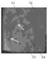
Fig. 5 is an X-ray image of a balloon marker, guide wire, stent, and guide catheter according to an embodiment of the present disclosure.
FIG. 6 is a flow chart of a tag and learning method according to an embodiment of the invention.
Fig. 7 is a block diagram of an exemplary computer system for real-time collimation and ROI-filter positioning in X-ray imaging in interventional procedures, in accordance with an embodiment of the present disclosure.
Detailed Description
Exemplary embodiments of the present disclosure as described herein generally include systems and methods for real-time collimation and ROI-filter positioning in X-ray imaging in interventional procedures. Accordingly, while the disclosure is susceptible to various modifications and alternative forms, specific embodiments thereof have been shown by way of example in the drawings and will herein be described in detail. It should be understood, however, that there is no intention to limit the disclosure to the specific forms disclosed, but on the contrary, the disclosure is to cover all modifications, equivalents, and alternatives falling within the spirit and scope of the disclosure.
As used herein, the term "image" refers to multi-dimensional data composed of discrete image elements (e.g., pixels for a 2-dimensional image and voxels for a 3-dimensional image). The image may be a medical image of the subject collected, for example, by computed tomography, magnetic resonance imaging, ultrasound, or any other medical imaging system known to those skilled in the art. The images may also be provided from non-medical contexts, such as, for example, remote sensing systems, electron microscopes, and the like. Although the image may be considered to be from R3To R or R7But the method of the present disclosure is not limited to such images and may be applied to images of any dimension, such as two-dimensional pictures or three-dimensional volumes. For two-dimensional or three-dimensional images, the domain of the image is typically a two-dimensional or three-dimensional rectangular array, where each pixel or voxel can be addressed with reference to a set of 2 or 3 mutually orthogonal axes. The terms "digital" and "digitized" as used herein will refer to images or volumes obtained via a digital or digitized format obtained by conversion from an analog image or acquired via a digital acquisition system, as appropriate.
Embodiments of the present disclosure may provide a method for minimizing scattered X-rays by automatically setting a collimator and an ROI filter in an optimal manner and in real time in consideration of the above-mentioned characteristics. Methods according to embodiments of the present disclosure may classify scenes into different categories based on the presence of a medical device or structure in a fluoroscopic image. According to embodiments of the present disclosure, the structure of the subject and the medical devices used in the procedure are referred to as "landmarks". Based on the detected scene categories, a model of the corresponding landmarks may be loaded to detect the locations of the landmarks in the image and generate collimator and ROI filter settings. For example, if an atrial fibrillation procedure is detected, models of an ablation catheter, a coronary sinus catheter, and a surrounding mapping catheter are automatically loaded. If no model exists for a landmark, the landmark is considered new and a "label and learn" method is used to allow a technician to initialize the landmark and then detect similar landmarks in the X-ray image. Adding the detected new landmark to the landmark database.
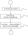
FIG. 2 is a flow diagram of an exemplary, non-limiting method for real-time collimation and ROI filter localization in X-ray imaging in interventional procedures via automatic detection and tracking of landmarks of interest. Referring now to the figure, the method begins at step 21 by acquiring a fluoroscopic image. If the fluoroscopic imaging system is a single wing system, the image is a single wing image, or otherwise a double wing frame. The image is acquired at the beginning of the procedure and includes the medical device at the time and after the X-ray imaging device has been centered at the region of interest of the patient or object.
After the initial image is captured, the images or scenes may be classified into different categories at step 22 based on the procedure being performed, since different medical procedures employ different medical devices and the fluoroscopic images have different regions of interest in the patient's body. According to embodiments of the present disclosure, a scene classification method uses low-level image features such as edges, Haar-like features, scale-invariant features, histogram of ordered gradients, Local Ternary Patterns (LTPs), and the like, and employs a classifier to classify scenes. An exemplary, non-limiting list of interventional procedures for classifying images includes electrophysiological procedures, intravascular ultrasound procedures, Chronic Total Occlusion (CTO) procedures, balloon angioplasty procedures, and the like.
Once the scene is determined, it may be determined at step 23 which landmarks to look for and a pre-trained classifier may be loaded to detect those landmarks. The determination as to which landmarks are present in the image may be performed automatically or manually by an operator. In manual mode, the operator examines the image and selects a landmark list from the candidate landmark list. Alternatively, in automatic mode, all pre-trained landmark models are loaded to detect the presence of landmarks in the image, from which a list of landmark models is selected. The pre-trained landmark models are landmark specific and are learned from a large number of annotated X-ray images. An exemplary, non-limiting list of pre-trained models for the following landmarks is as follows:
balloon markers typically present in stenting procedures;
a guide catheter typically present in IVUS procedures;
guidewires also present in IVUS and many other procedures;
an IVUS transducer;
blood vessels visible after contrast agent injection;
an ablation catheter electrode present in an ablation EP procedure;
peripheral mapping catheter electrodes also present in ablative EP procedures;
a coronary sinus catheter electrode used in an EP procedure;
calcium present in some interventional procedures; and
bone structure.
As an example, in the case of the stent procedure, the image of which is shown in fig. 3, the following models of landmarks are selected: (1) a guide catheter; (2) a balloon marker; and (3) a guide wire. A list of landmark models may be stored in a database.
An exemplary, non-limiting algorithm for detecting these three landmarks according to embodiments of the present disclosure is as follows.
Fig. 4 (a) -4 (c) illustrate the detection of the electrodes on the coronary sinus catheter. In fig. 4 (a), an arrow 41 indicates an electrode; in fig. 4 (b), point 42 is on the candidate electrode location; and (c) of fig. 4 shows candidate positions 43 detected after non-maximum suppression. The catheter tip and the electrode can be detected as an orientation point (x, y, θ) and can be parameterized by their position (x, y) and orientation (θ). For fast detection, boundary space learning may be used to first detect only tip and electrode positions (x, y) and then search for all orientations (θ) at the desired locations. Tip and electrode positions (x, y) may be detected using a trained binary classifier. An exemplary, non-limiting classifier uses about 100,000 Haar features in a centered window of (k × k) size. An exemplary, non-limiting classifier is a probability-driven tree (PBT) that can output a probability P (e = (x, y) | D), where D is a feature set. The catheter tip differs from the other electrodes in context and appearance, and it can be detected more reliably than the other electrodes. The detected electrodes and candidate positions are then augmented with a set of discrete orientations and provided to a trained orientation point detector, and the same applies to the detected tip position. An exemplary orientation point detector uses a richer pool of features, including steerable feature responses and image intensity differences with respect to query position and orientation. The set of electrodes and tips detected at each frame is provided to a non-maximum suppression (NMS) stage that selects aggregate detection. In each frame, a maximum of K electrodes and F tips are selected.
Similar to the detection of catheter electrodes, balloon marker detection according to embodiments of the present disclosure includes two steps. In a first step, the PBT classifier detects candidate flag locations, while in a second step, a pair of two candidate flags is evaluated by the other PBT classifier. Fig. 5 is an X-ray image of the balloon marker 51, guide wire 52, stent 53 and guide catheter 54.
An exemplary, non-limiting detection algorithm according to embodiments of the present disclosure of guidewires includes a semantic guidewire model that includes three sections, including a catheter tip, a guidewire tip, and a guidewire body. The detection of these different parts is integrated into a bayesian formulation for detecting the entire guideline. A layered and multi-resolution scheme is applied to efficiently detect the guideline.
Landmark detection according to embodiments of the present disclosure may be performed in parallel when other computational workloads, such as visualization and GUI interaction, are not required.
Referring again to fig. 2, in accordance with an embodiment of the present disclosure, for new types of landmarks, such as new medical devices or difficult to define patterns (such as calcifications), for which a pre-trained model is not available, the model may be learned online from user initialization using a label and learning approach at step 24. A flow diagram of a tagging and learning method according to an embodiment of the present disclosure is shown in fig. 6. Referring to fig. 6, at step 61, new landmarks may be initialized manually or semi-automatically by an operator. Exemplary non-limiting initializations include line segments, curves, bounding boxes, circles, or other similar types of structures. At step 62, negative samples are obtained from the rest of the image by user initialization of an example providing positive samples, and the image appearance is obtained by learning a template of initialized landmarks, where the template is an image block representing the appearance of a landmark. For example, a template matching based approach can be used in the patent application, which can track coronary sinus catheters in X-ray images in atrial fibrillation ablation procedures. Learning of a new landmark model is performed at step 63 by using positive samples, negative samples and image appearance.
Referring again to fig. 2, collimation is calculated and collimator settings are generated at step 25. Bounding box for computing all landmarks from landmark models Boundaries in conjunction with ROI filters
 . From these collimator settings can be generated
 . According to embodiments of the present disclosure, bounding boxes and ROI filter boundaries may be automatically determined based on what types of landmarks are important in a given scene. For example, for a stent implantation scenario, then the locations of the two balloon markers are important, and the image should define an ROI around the pair of balloon markers. An exemplary non-limiting collimator set-up is

Where it is assumed that the collimator setting defines a rectangle. According to other embodiments of the present disclosure, if the collimator has another shape, such as a circle, the settings of the collimator may be derived similar to the above. At step 26, the proposed collimator settings are shown to the operator for confirmation. The operator may accept these new settings to set the collimators, or reject the settings to update them.
A system according to embodiments of the present disclosure may track landmarks of interest as one or more landmarks move into a collimated area. At step 27, if the landmark of interest is detected as moving inside the collimation, the collimator and ROI filter settings are recalculated and shown to the operator for confirmation using steps 22-26 described above.
The method according to embodiments of the present disclosure may work automatically in real time with little or no manual input, except during system initialization and validation of updated collimator and ROI filter settings, but the operator may set these parameters manually at any time.
It is to be understood that embodiments of the present disclosure may be implemented in various forms of hardware, software, firmware, special purpose processes, or a combination thereof. In one embodiment, embodiments of the disclosure may be implemented in software as an application program tangibly embodied on a computer-readable program storage device. The application program may be uploaded to, and executed by, a machine comprising any suitable architecture.
Fig. 7 is a block diagram of an exemplary computer system for implementing a method for real-time collimation and ROI-filter positioning in X-ray imaging in interventional procedures, in accordance with an embodiment of the present disclosure. Referring now to FIG. 7, a computer system 71 for implementing embodiments of the present disclosure may include, among other things, a Central Processing Unit (CPU) 72, a memory 73, and an input/output (I/O) interface 74. The computer system 71 is typically coupled through the I/O interface 74 to a display 75 and various input devices 76 such as a mouse and a keyboard. The support circuits may include circuits such as cache, power supplies, clock circuits, and a communication bus. The memory 73 may include Random Access Memory (RAM), Read Only Memory (ROM), disk drives, tape drives, and the like, or a combination thereof. Embodiments of the present disclosure may be implemented as a routine 77 stored in memory 73 and executed by CPU 72 to process a signal from a signal source 78. As such, the computer system 71 is a general purpose computer system that becomes a specific purpose computer system when executing the routine 77 of the present disclosure.
The computer system 71 also includes an operating system and microinstruction code. The various processes and functions described herein may either be part of the microinstruction code or part of the application program (or a combination thereof), which is executed via the operating system. In addition, various other peripheral devices may be connected to the computer platform such as an additional data storage device and a printing device.
It is to be further understood that, because some of the constituent system components and method steps depicted in the accompanying figures may be implemented in software, the actual connections between the system components (or the process steps) may differ depending upon the manner in which the embodiments of the present disclosure are programmed. Given the teachings of the present disclosure provided herein, one of ordinary skill in the related art will be able to contemplate these and similar implementations or configurations of the present disclosure.
Although embodiments of the present disclosure have been described in detail with reference to example embodiments, those skilled in the art will appreciate that various modifications and substitutions can be made thereto without departing from the spirit and scope of the present disclosure as set forth in the appended claims.
Claims (24)
1. A system for real-time collimation and ROI-filter positioning in X-ray imaging in interventional procedures, comprising:
means for acquiring an image of a region of interest, ROI, on a subject at the start of a medical intervention procedure;
means for classifying an image based on low-level features in the image to determine a type of procedure being performed;
means for determining a list of landmarks in the image from the type of procedure being performed, and loading a pre-trained landmark model for each landmark in the list of landmarks, wherein a landmark comprises a medical device used in the medical interventional procedure and an anatomical structure of the subject; and
means for calculating collimator settings of an X-ray imaging device from ROI filter boundaries and bounding boxes of the landmarks calculated using the landmark model.
2. The system of claim 1, further comprising means for presenting the computed collimator settings of the X-ray imaging device to an operator and receiving confirmation of the operator of the computed collimator settings from the operator.
3. The system of claim 1, further comprising: means for detecting that a landmark has moved into the ROI and recalculating the ROI filter boundaries and the collimator settings of the X-ray imaging device during the medical intervention procedure.
4. The system of claim 1, wherein the landmark model is used to detect landmarks in the image.
5. The system of claim 4, wherein the landmark comprises a balloon marker, a guide catheter, a guide wire, an intravascular ultrasound transducer, a blood vessel, an ablation catheter electrode, a peripheral mapping catheter electrode, a coronary sinus catheter electrode, calcium, and a bone structure.
6. The system according to claim 4, wherein if a pre-trained landmark model is not exited for a landmark, the system further comprises means for initializing the landmark, receiving positive samples of the landmark from a user, receiving negative samples of the landmark from other regions of the image, determining an appearance of the image from an image patch representing the appearance of the initialized landmark, and training a landmark model using the positive samples, the negative samples, and the image appearance.
7. The system of claim 6, wherein the landmark is initialized with one of a line segment, a curve, a bounding box, or a circle.
8. The system of claim 1, wherein the low-level features include edges, Haar-like features, scale-invariant features, histogram of ordered gradients, and Local Ternary Patterns (LTPs).
9. The system of claim 1, wherein the images are classified by a classifier based on a type of procedure being performed, wherein the procedure types include an electrophysiology procedure, an intravascular ultrasound procedure, a Chronic Total Occlusion (CTO) procedure, and a balloon angioplasty procedure.
10. A system for real-time collimation and ROI-filter positioning in X-ray imaging in interventional procedures, comprising:
means for acquiring an image of a region of interest, ROI, on a subject at the start of a medical intervention procedure;
means for classifying the image based on a type of procedure being performed;
means for detecting a landmark in the image, wherein the landmark being detected is determined from the type of procedure being performed, wherein a landmark comprises a medical device used in the medical intervention procedure and an anatomical structure of the subject; and
means for calculating collimator settings of an X-ray imaging device from ROI filter boundaries and bounding boxes of the landmarks calculated using the detected landmarks.
11. The system of claim 10, further comprising means for determining a landmark list from the type of procedure being performed and loading a pre-trained landmark model for each landmark in the landmark list, wherein the landmark model is used to detect landmarks in the image.
12. The system according to claim 11, wherein if a pre-trained landmark model is not exited for a landmark, the system further comprises means for initializing the landmark, receiving positive samples of the landmark from a user, receiving negative samples of the landmark from other regions of the image, determining an appearance of the image from an image patch representing the appearance of the initialized landmark, and training a landmark model using the positive samples, the negative samples, and the image appearance.
13. The system of claim 10, further comprising means for presenting the computed collimator settings of the X-ray imaging device to an operator and receiving confirmation of the operator of the computed collimator settings from the operator.
14. The system of claim 10, further comprising: means for detecting that a landmark has moved into the ROI and recalculating the ROI filter boundaries and the collimator settings of the X-ray imaging device during the medical intervention procedure.
15. The system of claim 10, wherein the images are classified using low-level features, wherein the low-level features include edges, Haar-like features, scale-invariant features, histogram of ordered gradients, and Local Ternary Patterns (LTPs).
16. A computer readable non-transitory program storage device tangibly embodying a program of instructions executable by a computer to perform method steps for real-time collimation and ROI-filter positioning in X-ray imaging in interventional procedures, the method comprising the steps of:
acquiring an image of a region of interest, ROI, on a subject at the start of a medical intervention procedure;
classifying the image based on low-level features in the image to determine a type of procedure being performed;
determining a list of landmarks in the image from the type of procedure being performed and loading a pre-trained landmark model for each landmark in the list of landmarks, wherein a landmark comprises a medical device used in the medical intervention procedure and an anatomical structure of the subject; and
collimator settings of an X-ray imaging device are calculated from ROI filter boundaries and bounding boxes of the landmarks calculated using the landmark model.
17. The computer readable non-transitory program storage device of claim 16, the method further comprising presenting the computed collimator settings of the X-ray imaging device to an operator and receiving confirmation of the operator of the computed collimator settings from the operator.
18. The computer-readable non-transitory program storage device of claim 16, the method further comprising: during the medical intervention procedure, it is detected that a landmark has moved into the ROI, and the ROI filter boundaries and the collimator settings of the X-ray imaging device are recalculated.
19. The computer readable non-transitory program storage device of claim 16, wherein the landmark model is used to detect landmarks in the image.
20. The computer readable non-transitory program storage device of claim 19, wherein the landmarks include balloon markers, guide catheters, guide wires, intravascular ultrasound transducers, blood vessels, ablation catheter electrodes, peripheral mapping catheter electrodes, coronary sinus catheter electrodes, calcium, and bone structures.
21. The computer readable non-transitory program storage device of claim 19, wherein if a pre-trained landmark model is not exited for a landmark, the method further comprises initializing the landmark, receiving positive samples of the landmark from a user, receiving negative samples of the landmark from other areas of the image, determining an appearance of the image from an image patch representing the appearance of the initialized landmark, and training a landmark model using the positive samples, the negative samples, and the image appearance.
22. The computer readable non-transitory program storage device of claim 21, wherein the landmark is initialized with one of a line segment, a curve, a bounding box, or a circle.
23. The computer-readable non-transitory program storage device of claim 16, wherein the low-level features include edges, Haar-like features, scale-invariant features, histogram of ordered gradients, and Local Ternary Patterns (LTPs).
24. The computer readable non-transitory program storage device of claim 16, wherein the images are classified by a classifier based on a type of procedure being performed, wherein the procedure types include an electrophysiology procedure, an intravascular ultrasound procedure, a Chronic Total Occlusion (CTO) procedure, and a balloon angioplasty procedure.
Applications Claiming Priority (1)
| Application Number | Priority Date | Filing Date | Title |
|---|---|---|---|
| PCT/US2015/034792 WO2016200370A1 (en) | 2015-06-09 | 2015-06-09 | Real-time collimation and roi-filter positioning in x-ray imaging via automatic detection of the landmarks of interest |
Publications (2)
| Publication Number | Publication Date |
|---|---|
| CN107809955A CN107809955A (en) | 2018-03-16 |
| CN107809955B true CN107809955B (en) | 2021-01-19 |
Family
ID=53433322
Family Applications (1)
| Application Number | Title | Priority Date | Filing Date |
|---|---|---|---|
| CN201580080774.2A Active CN107809955B (en) | 2015-06-09 | 2015-06-09 | Real-time collimation and ROI-filter localization in X-ray imaging via automatic detection of landmarks of interest |
Country Status (4)
| Country | Link |
|---|---|
| US (1) | US10268915B2 (en) |
| EP (2) | EP3656309A1 (en) |
| CN (1) | CN107809955B (en) |
| WO (1) | WO2016200370A1 (en) |
Families Citing this family (12)
| Publication number | Priority date | Publication date | Assignee | Title |
|---|---|---|---|---|
| US10417763B2 (en) * | 2014-07-25 | 2019-09-17 | Samsung Electronics Co., Ltd. | Image processing apparatus, image processing method, x-ray imaging apparatus and control method thereof |
| US10342505B2 (en) | 2016-03-31 | 2019-07-09 | General Electric Company | System and method for adjusting a radiation dose during imaging of an object within a subject |
| CN108937975A (en) * | 2017-05-19 | 2018-12-07 | 上海西门子医疗器械有限公司 | X-ray exposure area adjusting method, storage medium and X-ray system |
| CN107871319B (en) * | 2017-11-21 | 2021-09-17 | 上海联影医疗科技股份有限公司 | Method and device for detecting beam limiter area, X-ray system and storage medium |
| GB2575795A (en) * | 2018-07-23 | 2020-01-29 | Medsolve Ltd | Imaging system for use in a fluoroscopy procedure |
| EP3824475B1 (en) * | 2019-02-14 | 2023-06-14 | Brainlab AG | Automatic setting of imaging parameters |
| US11707255B2 (en) * | 2019-04-02 | 2023-07-25 | Siemens Medical Solutions Usa, Inc. | Image-based probe positioning |
| DE102020204454A1 (en) | 2019-05-14 | 2020-11-19 | Siemens Healthcare Gmbh | Monitoring treatment of an object |
| JP2020185145A (en) * | 2019-05-14 | 2020-11-19 | 株式会社島津製作所 | X-ray imaging apparatus |
| JP2022549190A (en) * | 2019-09-20 | 2022-11-24 | キヤノン ユーエスエイ,インコーポレイテッド | Artificial intelligence co-registration and marker detection including machine learning and use of its results |
| DE102020213035A1 (en) * | 2020-10-15 | 2022-04-21 | Siemens Healthcare Gmbh | Method for controlling an X-ray device and medical system |
| DE102021214738A1 (en) | 2021-12-20 | 2023-06-22 | Siemens Healthcare Gmbh | Control method for X-ray device and X-ray device |
Family Cites Families (23)
| Publication number | Priority date | Publication date | Assignee | Title |
|---|---|---|---|---|
| US5278887A (en) | 1992-06-29 | 1994-01-11 | Siemens Corporate Research, Inc. | Apparatus and method for reducing X-ray dosage during a fluoroscopic procedure |
| DE69529857T2 (en) * | 1994-03-25 | 2004-01-08 | Kabushiki Kaisha Toshiba, Kawasaki | Radiotherapy System |
| US6055295A (en) | 1998-01-29 | 2000-04-25 | Siemens Corporate Research, Inc. | Method and apparatus for automatic collimation in x-ray peripheral imaging |
| JP3513700B2 (en) | 2000-03-29 | 2004-03-31 | 稔 植松 | Mobile radiation shielding device |
| ATE485770T1 (en) | 2003-07-30 | 2010-11-15 | Koninkl Philips Electronics Nv | X-RAY DEVICE WITH AUTOMATICALLY ADJUSTABLE COLLIMATOR |
| US8423121B2 (en) | 2008-08-11 | 2013-04-16 | Siemens Aktiengesellschaft | Method and system for guidewire tracking in fluoroscopic image sequences |
| US9280837B2 (en) * | 2008-10-10 | 2016-03-08 | Koninklijke Philips N.V. | Angiographic image acquisition system and method with automatic shutter adaptation for yielding a reduced field of view covering a segmented target structure or lesion for decreasing X-radiation dose in minimally invasive X-ray-guided interventions |
| US8311308B2 (en) | 2009-12-10 | 2012-11-13 | Siemens Corporation | Stent viewing using a learning based classifier in medical imaging |
| US8548213B2 (en) | 2010-03-16 | 2013-10-01 | Siemens Corporation | Method and system for guiding catheter detection in fluoroscopic images |
| US8565859B2 (en) | 2010-06-29 | 2013-10-22 | Siemens Aktiengesellschaft | Method and system for image based device tracking for co-registration of angiography and intravascular ultrasound images |
| US8892186B2 (en) | 2010-09-20 | 2014-11-18 | Siemens Aktiengesellschaft | Method and system for detection and tracking of coronary sinus catheter electrodes in fluoroscopic images |
| WO2012123850A1 (en) * | 2011-03-15 | 2012-09-20 | Koninklijke Philips Electronics N.V. | Medical imaging device for providing an image representation supporting in positioning an intervention device |
| US9002436B2 (en) | 2011-09-19 | 2015-04-07 | Siemens Aktiengesellschaft | Method and system for ablation catheter and circumferential mapping catheter tracking in fluoroscopic images |
| JP6175070B2 (en) * | 2011-12-14 | 2017-08-02 | コーニンクレッカ フィリップス エヌ ヴェKoninklijke Philips N.V. | Real-time feedback to prevent high-dose C-arch geometry |
| US9700276B2 (en) | 2012-02-28 | 2017-07-11 | Siemens Healthcare Gmbh | Robust multi-object tracking using sparse appearance representation and online sparse appearance dictionary update |
| US20130272504A1 (en) * | 2012-04-16 | 2013-10-17 | Meir Deutsch | X-Ray Dose Reduction by Controlled Shutter Speed |
| JP2015533533A (en) | 2012-08-27 | 2015-11-26 | コーニンクレッカ フィリップス エヌ ヴェKoninklijke Philips N.V. | Automatic collimation conscious of doctor |
| WO2014033614A1 (en) * | 2012-08-27 | 2014-03-06 | Koninklijke Philips N.V. | Patient-specific and automatic x-ray system adjustment based on optical 3d scene detection and interpretation |
| JP2014054425A (en) * | 2012-09-13 | 2014-03-27 | Toshiba Corp | X-ray diagnostic apparatus |
| US20140187923A1 (en) * | 2012-12-28 | 2014-07-03 | General Electric Company | Collimator for imaging system and method for using the same |
| EP2991555B1 (en) * | 2013-04-03 | 2018-10-17 | Koninklijke Philips N.V. | Interventional x-ray system |
| US9420976B2 (en) * | 2014-03-19 | 2016-08-23 | General Electric Company | Systems and methods for optimized source collimation |
| KR20160007121A (en) * | 2014-07-11 | 2016-01-20 | 삼성전자주식회사 | X-ray apparatus |
-
2015
- 2015-06-09 CN CN201580080774.2A patent/CN107809955B/en active Active
- 2015-06-09 WO PCT/US2015/034792 patent/WO2016200370A1/en unknown
- 2015-06-09 EP EP19204288.5A patent/EP3656309A1/en not_active Withdrawn
- 2015-06-09 US US15/574,203 patent/US10268915B2/en active Active
- 2015-06-09 EP EP15730033.6A patent/EP3307169B1/en active Active
Also Published As
| Publication number | Publication date |
|---|---|
| EP3656309A1 (en) | 2020-05-27 |
| EP3307169A1 (en) | 2018-04-18 |
| WO2016200370A1 (en) | 2016-12-15 |
| US20180129896A1 (en) | 2018-05-10 |
| EP3307169B1 (en) | 2020-07-29 |
| US10268915B2 (en) | 2019-04-23 |
| CN107809955A (en) | 2018-03-16 |
Similar Documents
| Publication | Publication Date | Title |
|---|---|---|
| CN107809955B (en) | Real-time collimation and ROI-filter localization in X-ray imaging via automatic detection of landmarks of interest | |
| US10111726B2 (en) | Risk indication for surgical procedures | |
| US9687204B2 (en) | Method and system for registration of ultrasound and physiological models to X-ray fluoroscopic images | |
| US9155470B2 (en) | Method and system for model based fusion on pre-operative computed tomography and intra-operative fluoroscopy using transesophageal echocardiography | |
| US8073221B2 (en) | System for three-dimensional medical instrument navigation | |
| US20150223773A1 (en) | Method and Apparatus for Image Fusion Based Planning of C-Arm Angulation for Structural Heart Disease | |
| US9721379B2 (en) | Real-time simulation of fluoroscopic images | |
| EP3224804B1 (en) | Apparatus for determining positions of an interventional instrument in a projection image | |
| JP2012115635A (en) | Image processing method, image processing apparatus, imaging system, and program code | |
| CN102257532B (en) | Combined device-and-anatomy boosting | |
| CN110301883B (en) | Image-based guidance for navigating tubular networks | |
| CN113171174A (en) | Orientation detection in fluoroscopic images | |
| CN108430376B (en) | Providing a projection data set | |
| US20210174523A1 (en) | Method for registration of image data and for provision of corresponding trained facilities, apparatus for doing so and corresponding computer program product | |
| EP2956065B1 (en) | Apparatus for image fusion based planning of c-arm angulation for structural heart disease | |
| Chen et al. | Deep learning based non-rigid device tracking in ultrasound image | |
| Hatt et al. | Depth‐resolved registration of transesophageal echo to x‐ray fluoroscopy using an inverse geometry fluoroscopy system | |
| JP7303144B2 (en) | Radiation imaging apparatus, object detection program for radiographic image, and object detection method for radiographic image | |
| US8948486B2 (en) | Method to process radiological images | |
| CN116763401A (en) | Puncture path planning system, method and surgical robot | |
| Ashammagari | A Framework for Automating Interventional Surgeries (Catheter detection and Automation of a crucial step in Percutaneous Coronary Interventional surgery-PCI) | |
| CN113557518A (en) | Controlling medical data processing using current workflow steps | |
| Baker et al. | Systems and Methods for Image Guided Surgery | |
| Soper | A navigation system for an ultrathin scanning fiber bronchoscope in the peripheral airways |
Legal Events
| Date | Code | Title | Description |
|---|---|---|---|
| PB01 | Publication | ||
| PB01 | Publication | ||
| SE01 | Entry into force of request for substantive examination | ||
| SE01 | Entry into force of request for substantive examination | ||
| GR01 | Patent grant | ||
| GR01 | Patent grant |