CN1077347C - Self-starting brushless electric motor - Google Patents
Self-starting brushless electric motor Download PDFInfo
- Publication number
- CN1077347C CN1077347C CN96195652A CN96195652A CN1077347C CN 1077347 C CN1077347 C CN 1077347C CN 96195652 A CN96195652 A CN 96195652A CN 96195652 A CN96195652 A CN 96195652A CN 1077347 C CN1077347 C CN 1077347C
- Authority
- CN
- China
- Prior art keywords
- utmost point
- motor
- permanent
- asymmetric
- row
- Prior art date
- Legal status (The legal status is an assumption and is not a legal conclusion. Google has not performed a legal analysis and makes no representation as to the accuracy of the status listed.)
- Expired - Lifetime
Links
Images


Classifications
-
- H—ELECTRICITY
- H02—GENERATION; CONVERSION OR DISTRIBUTION OF ELECTRIC POWER
- H02K—DYNAMO-ELECTRIC MACHINES
- H02K1/00—Details of the magnetic circuit
- H02K1/06—Details of the magnetic circuit characterised by the shape, form or construction
- H02K1/22—Rotating parts of the magnetic circuit
- H02K1/24—Rotor cores with salient poles ; Variable reluctance rotors
- H02K1/246—Variable reluctance rotors
-
- H—ELECTRICITY
- H02—GENERATION; CONVERSION OR DISTRIBUTION OF ELECTRIC POWER
- H02K—DYNAMO-ELECTRIC MACHINES
- H02K19/00—Synchronous motors or generators
- H02K19/02—Synchronous motors
- H02K19/04—Synchronous motors for single-phase current
- H02K19/06—Motors having windings on the stator and a variable-reluctance soft-iron rotor without windings, e.g. inductor motors
-
- H—ELECTRICITY
- H02—GENERATION; CONVERSION OR DISTRIBUTION OF ELECTRIC POWER
- H02K—DYNAMO-ELECTRIC MACHINES
- H02K21/00—Synchronous motors having permanent magnets; Synchronous generators having permanent magnets
- H02K21/12—Synchronous motors having permanent magnets; Synchronous generators having permanent magnets with stationary armatures and rotating magnets
- H02K21/14—Synchronous motors having permanent magnets; Synchronous generators having permanent magnets with stationary armatures and rotating magnets with magnets rotating within the armatures
- H02K21/16—Synchronous motors having permanent magnets; Synchronous generators having permanent magnets with stationary armatures and rotating magnets with magnets rotating within the armatures having annular armature cores with salient poles
-
- H—ELECTRICITY
- H02—GENERATION; CONVERSION OR DISTRIBUTION OF ELECTRIC POWER
- H02K—DYNAMO-ELECTRIC MACHINES
- H02K21/00—Synchronous motors having permanent magnets; Synchronous generators having permanent magnets
- H02K21/38—Synchronous motors having permanent magnets; Synchronous generators having permanent magnets with rotating flux distributors, and armatures and magnets both stationary
- H02K21/44—Synchronous motors having permanent magnets; Synchronous generators having permanent magnets with rotating flux distributors, and armatures and magnets both stationary with armature windings wound upon the magnets
-
- H—ELECTRICITY
- H02—GENERATION; CONVERSION OR DISTRIBUTION OF ELECTRIC POWER
- H02K—DYNAMO-ELECTRIC MACHINES
- H02K29/00—Motors or generators having non-mechanical commutating devices, e.g. discharge tubes or semiconductor devices
- H02K29/03—Motors or generators having non-mechanical commutating devices, e.g. discharge tubes or semiconductor devices with a magnetic circuit specially adapted for avoiding torque ripples or self-starting problems
Landscapes
- Engineering & Computer Science (AREA)
- Power Engineering (AREA)
- Permanent Magnet Type Synchronous Machine (AREA)
- Permanent Field Magnets Of Synchronous Machinery (AREA)
- Synchronous Machinery (AREA)
- Iron Core Of Rotating Electric Machines (AREA)
- Brushless Motors (AREA)
- Control Of Motors That Do Not Use Commutators (AREA)
Abstract
A self-starting brushless electric motor having a first motor part (stator) (11) with poles arranged in a row, said poles constituting ferromagnetic poles (13S) or permament-magnet poles (14A), a second motor part (rotor) (12) with poles arranged in a row, said poles consisting of ferromagnetic poles (16A) or permanent-magnet poles and being arranged opposite the row of poles on the first motor part (11), wherein the motor part with salient ferromagnetic poles or, if both motor parts have salient ferromagnetic poles, at least one of the motor parts has a permanent-magnet pole, and also a magnetizing winding on the first motor part. The system of poles formed by the pole rows is magnetically asymmetrical in the direction in which the motor parts (11, 12) are movable in relation to each other.
Description
The present invention relates to one type self-starting brushless electric motor, the type motor is included in the motor portion of two relative motions the magnetic resistance utmost point (ferromagnetic salient pole) at least one and the one or more permanent-magnet poles in this electrode systems.
Self-starting brushless electric motor can be powered with the electric current of unipolar DC pulse power supply or alternating polarity.When the motor with medium shaft power was powered, direct current pulse power source used the electronic switch of minimal amount and obtains motor thus and the minimum system cost of power supply electronic installation.On the other hand, when in any case the electronic switch number in the power supply electronic installation in motor must increase, can advantageously supply with the electric current of alter polarity to motor, so that on two half periods, electrical power is supplied with motor, obtain more uniform torque output thus and make that conduction loss reduces in the winding.
Only be provided with a winding by the power supply of single external current source in brushless single phase motor, it is located on of two or more parts of rotating each other or moving.This motor can self-starting, and promptly when produce driving torque in a predetermined direction when static, this predetermined direction is preferential starting direction, and only with this starting direction be intrinsic when the motor designs be condition.Self-starting on privileged direction can be provided with asymmetry in the heart and reach at the soft magnet of motor, for example by using asymmetric salient pole and/or asymmetric permanent-magnet pole, or setting is free of attachment to the auxiliary winding on the external power, the short-circuit current paths in for example known non salient pole motor.This current path only with the influence of the changes of magnetic field of these current path interlinkages under conducting electric current.For when motor is static, making electric current flow into these current paths, and must supply with pulse or alternating current in the winding that external power is connected.
Can illustrate in theory, not establish auxiliary winding but even when the motor winding cuts off the power supply, still on arbitrary turning to, apply in the motor of torque and must always comprise permanent-magnet pole.
Only limit to the motor that rotatablely moves in the following description, it has the first that is provided with winding, hereinafter referred to as stator, and be arranged in the stator and can be relatively its second portion of rotating, hereinafter referred to as rotor.But, be appreciated that, the commutative position of these two parts, the air gap that stator and rotor separate is not necessarily columniform, but also can be flat or taper comparably, and the relative motion between these two parts of motor differs and is decided to be rotation, also can be combining of linear movement or rotation and straight line comparably, also promptly side by side reaches along rotating shaft to move around the shaft.
The function of motor can be described to comprise the work period that the given number of times of revolution is repeated.When low-down speed, during for example from static starting, design was made up of the alive part of winding and the currentless another part of winding with the work period of the motor of unipolarity DC pulse power supply.For the motor of design with alternating polarity current impulse power supply, the work period by winding by the part of a polarity electric current, the currentless part of following, and then be that another currentless part of this work period is formed again with power a part to winding of reversed polarity electric current then.
In no current state, rotor must reach the start position, it also is such position, if winding passes to electric current on this position, to cause driving torque, i.e. torque on motor privileged direction, it is large enough to overcome motor and/or by friction torque any in the motor driven object or similar resistive torque.The torque that in motor, produces by permanent magnetism power must keep its direction and enough by force so that rotor till can be by excitatory position.Be appreciated that need be under no current state the torque output device, promptly motor must comprise at least one permanent-magnet pole.
According to described principle work and to present the motor of magnetic asymmetry in electrode systems known by WO 09/02437 and WO 92/12567.An object of the present invention is the motor of the type of motor representative in the above-mentioned open source literature is improved.
This purpose is by means of realizing by setting up the magnetic pumping stator that claims limit and the structure of rotor part (utmost point).
Except the possibility that the implementation structure alternative embodiment is provided, the present invention also provide increase in power-turning motor that motor produces in torque and the linear motor for linear force or " attraction "-possibility, this is following one or more aspect:
The rotor with the no current motor that-increase is produced by permanent-magnet pole is moved the torque on the immediate start position to.The application facet of high friction torque may appear in this improvement in being driven object, will be favourable as the driving shaft seal.
-increase the torque that in start position and winding thereof, occurs in the motor during by obtainable maximum current when stationary rotor.This improvement also is favourable under state described in the last joint.
-increase air gap power under given thermal losses condition-at least in certain embodiments, obtain being used for the littler of given purposes and preferable economically motor thus, when for some application, it will have very big advantage when low motor weight is most important, this class application examples is as being handheld tool or other hand-held object, if and when the inevitable cost increase of power supply electronic installation can not be offset this effect, also be favourable economically usually.
The parts that relate to magnetic pumping in the motor of the present invention are as follows:
Coil on the-stator:
Coil constitutes the single current circuit and can connect and/or be connected in parallel in principle.When power supply electronic installation when being made up of the unit of a plurality of parallel operations, every unit can be connected on its coil or on the coil groups, it is such to constitute single circuit like them.Can use two parts winding to replace winding is supplied with the electric current of alternating polarity, these two " half winding " powered with the unipolarity electric current, but these two " half windings " have opposite magnetic direction.
The salient pole of-ferromagnetic material (the magnetic resistance utmost point)
In most of motor according to the present invention, ferromagnetic salient pole claims also that hereinafter the magnetic resistance utmost point can be positioned on the stator, and they are used on the stator individually or with permanent-magnet pole.
Also can on rotor, be provided with the magnetic resistance utmost point, but preferably not mix use with permanent-magnet pole.Also can on rotor, consider the mixing use of these utmost point types, but nonsensical usually.
Extremely all magnetic is asymmetric at stator and epitrochanterian magnetic resistance.For the asymmetric stator poles of magnetic, its asymmetric part should be located on the direction opposite with the preferential direction of motion of motor, and should be on the direction identical with the preferential direction of motion in its asymmetric part on the rotor.
Replace or additionally, the magnetic resistance utmost point be set on both at stator and rotor, still, these magnetic resistance utmost points with above-mentioned side in the opposite direction on some magnetic asymmetry of performance, and this can not make motor not work.
-permanent-magnet pole
Only permanent-magnet pole must always be set on stator at the motor that is provided with the magnetic resistance utmost point on the rotor.Permanent-magnet pole on stator preferably magnetic is flat permanent, i.e. the number of poles order of two kinds of polarity and measure-alike.
In some cases, if permanent-magnet pole is asymmetric, will be favourable.
Design is used for supplying with the motor unipolarity current impulse and that have the p-m rotor utmost point and must always permanent-magnet pole will be set on stator.If to be shapes asymmetric and have main pole part and interpole part for these permanent-magnet poles, their main pole part can be advantageously moving in the opposite direction with the side of interpole part, if be that position symmetry and that it should have when only partly being made up of main pole begins to move from this utmost point for example.
The motor that is provided with the p-m rotor utmost point can not have permanent-magnet pole on stator.This motor only could self-starting when powering with the alternating polarity current impulse.Have more uniform torque output and higher average torque for this motor of given winding loss with comparing by the motor of unipolarity current impulse power supply.
Permanent-magnet pole, symmetry and asymmetric both all can have crooked end or edge, i.e. the edge that extends on angled with the armature spindle direction.In some cases, the bending at this permanent-magnet pole edge is very favourable to motor function.These curved edges not necessarily make geometry.Form by the line of demarcation (border region) that relates to the magnetic polarization marking (for example in permanent-magnet pole) for these edges just enough, above promptly these markings are printed on when permanent-magnet pole is magnetized.
The line of demarcation of these same magnetized areas may not extended linearly, and can not make motor function be subjected to influence greatly.
In the present invention and set up in the scope of claims, the magnetic asymmetry can be reached by multiple mode, and in them some are described as follows.
As motor in the prior art, the magnetic asymmetry is intended to set up in the motor a preferential starting direction, but also is used for other purpose according to the magnetic asymmetry in the motor of the present invention.
Basically, the attached purpose of the magnetic asymmetry of using in the present invention is to extend alleged " leading into distance " here.It is such distance, a utmost point on motor portion on this distance be permanent-magnet pole or be subjected to the excitatory magnetic resistance utmost point can attract a utmost point on another motor portion and be enough to cause these two utmost points each other from first settling position, as attract the position move next settling position mutually to, as the start position, in the alignment and therefore do not have magnetic pull (only on the direction of this direction of crosscut, magnetic pull being arranged) on the direction of relative movement between these the two poles of the earth on the magnetic each other of these two utmost points on the start position.
Leading between moving period, the magnetic conductivity between these two utmost points or in other words should increase to maximum constantly through the magnetic flux between them (the supposition magnetic potential is constant), and it occurs in when aliging on these two utmost point magnetic.The extension of therefore leading distance need descend at the mean value that leads flux change rate on the distance.
This decline realizes by means of the magnetic asymmetry, for example an interpole part of extending is set on extremely on corresponding preferential starting direction at least one, so that this utmost point will have a main pole part and an interpole part, the latter has determined preferential starting direction.
In the start position and attract on the position, the interpole part extends near next utmost point (from corresponding preferential starting direction) of another motor portion the point at least, and its may even cover this utmost point a little.But the cover part of interpole part can not have the magnetic flux of measuring on the unit overlay length circumference big the cover part that resembles the main pole part.
Suppose that extend vertically the front end and the rear end of stator poles and rotor pole in the turning motor of selecting by the example mode, the in most of the cases available in principle following manner of the magnetic asymmetry of stator poles is considered.The rotor of motor uses the even ferromagnetic cylinder with the rotor same diameter to replace, and when this cylinder rotate so that vertically the line of the periphery of Yan Shening will extend axially line along periphery and measure air gap flux density preferentially turning to when passing through the utmost point.Obtained the magnetic flux density (as the mean value on line length) measured function curve with respect to the relative angular position of this line and the utmost point, it from begin more or less equably near zero point at utmost point front end or with more or less significantly step rise to constant value under the main pole part and reach and sharply descend in utmost point rear end then.If this utmost point is symmetrical, then this curve will be symmetry and a similar Gaussian curve.
Suitable modification to mentioned above principle also can be applicable to other situation, for example when the magnetic asymmetry of the utmost point of the non axial extension of front and back ends of investigating the rotor pole or the utmost point.For example, extreme portion is a situation crooked and that extend along a helix thus, measures by the magnetic flux density of carrying out along corresponding sweep and can make investigation.
Under the situation of the permanent-magnet pole with even radial dimension and even diametrical magnetization, the asymmetry of magnetic pole can be produced by utmost point shape, and for example, the front end of the utmost point and rear end upwards can have different length at motor reel.By in the ring of the permanent magnetic material of uniform thickness, also obtaining similar effects with corresponding shape magnetization " the seal utmost point " (imprinting pole).In the case, the shape of permanent-magnetic clamp and magnetizing pattern or " magnet shape " are irrelevant.
The asymmetry of magnetic pole also can reach (even the width of utmost point place air gap changes) by being arranged on the permanent-magnet pole that its front end and rear end have different radial dimensions respectively on the direction of motor two parts relative motion, but gives uniform hard magnetization on its whole volume.
Certainly also can side by side use several different methods, so that it is asymmetric to obtain the magnetic of permanent-magnet pole.
For ferromagnetic salient pole is that the magnetic resistance utmost point also has several different methods and obtains the magnetic asymmetry.A kind of method is this pole-face to be arranged to asymmetric on the direction extending axially of motor facing to the surface of air gap, and whole in the case extremely surface will be positioned on the identical radial distance of rotating shaft.
Other method is that the face (in the face of the surface of air gap) that the magnetic resistance utmost point is stretched out makes symmetry, and change its radial distance apart from rotating shaft, promptly change width step by step or continuously along extremely surperficial air gap with respect to one on another motor portion imagination surface (face of cylinder).
The third method is the saturation flux density that changes along extremely surperficial.This is by using different magnetic materials to reach to the different piece of salient pole, or the activity coefficient of change lamination magnetic pole iron, or reach by the punching press slotted eye, for example, (actual thus pole-face presents evenly) punching below actual pole-face, or by changing interpole radial dimension partly so that the shape that it has the beak profile of image curvature reaches.
Certainly use simultaneously and reach the asymmetric several different methods of magnetic.Select how to obtain asymmetry and depend on the manufacturing cost of actual motor and the balance between the power supply electronic installation cost usually, because the selection of asymmetric type is included in influence the specification of the power electronic switching device in the power supply electronic installation.
As what will illustrate, in implementing the motor of magnetic asymmetry of the present invention, not only make indivedual utmost points of the utmost point group relevant possess feature with public winding coil, this public winding makes the magnetic field that the utmost point of all utmost point groups will produce in the time of will being subjected to this coil excited target.And make whole utmost point group possess feature and not only asymmetric and also reach by the asymmetric layout of indivedual utmost points in the utmost point group or on the rotor by the magnetic of one or more indivedual utmost points.
If when rotor pole it with stator poles magnetic positions aligning and rotor on arbitrary utmost point and dissimilar stator poles when stator only has permanent-magnet pole are when moving between the utmost point magnetic of opposed polarity next adjacent position of aliging, rotor pole moves distance be longer than or be shorter than rotor polar distance half, then the utmost point of a utmost point group will be arranged asymmetricly on the stator.
In other words, if when rotor is that the start position is in when moving between next position, back of attracting the position or next front position to rotor pole (can be arbitrary rotor pole), the traversing distance of rotor pole is longer than or is shorter than rotor polar distance half in rotor pole and permanent-magnet pole magnetic positions aligning, for example, will arrange with respect to the magnetic resistance utmost point in same or the different poles group in epitrochanterian permanent-magnet pole asymmetricly.
In a similar fashion, the magnetic asymmetry that is produced by asymmetric layout also can be present in the rotor.For example, comprise the permanent-magnet pole of alter polarity in rotor pole row, arctic permanent-magnet pole can be apart from the center either direction top offset between the permanent-magnet pole of the South Pole, and makes the utmost point of all identical polars equidistant basically.
Be noted that a utmost point group (pole unit) can comprise the single utmost point or a plurality of utmost points relevant with magnetizing coil in description of the invention.
A plurality of example embodiment of representing now with reference to summary in the accompanying drawings describe the present invention in detail.
Figure 1A represents the end-view of first embodiment of a turning motor.Its stator has two identical utmost point groups of opposition diametrically, and each is made up of the magnetic resistance utmost point and a layout asymmetric permanent-magnet pole therebetween of two symmetries, and is provided with field winding.Rotor has four asymmetric magnetic resistance utmost points, and they are in the turned position that has attracted fully among the figure;
Figure 1B is the motor utmost point row expanded view of seeing from air gap partly, and they have removed the service position in the axial direction, but the relation each other of its position still is in the position relation of Figure 1A;
Fig. 1 C represents the motor with Figure 1A same way as, and is decorated with the permanent magnetic field line of force in stator and the rotor;
Fig. 1 D is the longitdinal cross-section diagram of motor among Fig. 1;
Fig. 1 E is the figure that is similar to Figure 1B, but expression rotor and stator poles be on same axial location and move to different relative positions, and also comprises a curve chart that is illustrated in the magnetic attraction that acts between the magnetic resistance utmost point on the permanent-magnet pole and rotor on the stator;
Fig. 2 A, 2B and 2C be with Figure 1A, the corresponding mode of 1B and 1C represent second
Embodiment;
Fig. 3 A, 3B to 12A, 12B are other each embodiment that represents with Figure 1A and the corresponding mode of 1B;
Figure 13 A to 13D is the expanded view that is similar to the utmost point combination of Figure 1B, and they are each other in the shape of the stator permanent magnet utmost point and arrange different;
Figure 14 A, 14B are expression Figure 1A, the part figure of the remodeling of the stator magneto resistance utmost point shown in the 1B.
In institute's drawings attached, the permanent-magnet pole polarity of a plurality of diametrical magnetizations is to be represented by the arrow that points to the magnet north pole side.
In addition, in all embodiment shown in the drawings, the asymmetry of stator and/or rotor pole is to guide like this, and promptly the preferred starting direction of rotor is a counter-clockwise direction.
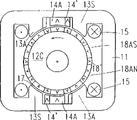
Motor shown in Figure 1A-1C is a turning motor, as other motor, it also is that first motor portion of lamination ferromagnetic material stator 11 forms and second motor portion of lamination ferromagnetic material rotor 12 forms are arranged, and rotor rotates rotor by the suitable bearings bearing journal shown in Fig. 1 D in stator.The rotating shaft of rotor is represented by the small circle of tape label 12A, and preferential rotation direction is represented (being counter-clockwise direction in all illustrated embodiment) with arrow.
For each utmost point group, stator 11 is provided with a coil 15 on this utmost point group, and it forms the part of shared magnetization winding.
In the outside of rotor 12,, also claim the magnetic resistance utmost point around its periphery four ferromagnetic salient pole 16A that anisotropically distributing.These pole-faces are positioned at its center on the cylinder on the rotating shaft 12A to the surface of stator, its apart from the distance in axle center less than the distance of the cylinder that comprises stator pole faces, so that stator pole faces and rotor pole faces form an air-gap 17 in the middle of their apart from the axle center.The pole span of rotor 12 is corresponding to the distribution of magnetic resistance utmost point 13S in stator 11 every utmost point groups.
In the embodiment shown in Figure 1A to 1D, all utmost point 13S on the stator 11, all utmost point 16A on 14A and the rotor 12 are arranged in the same plane perpendicular to armature spindle, so that during rotation, on the rotor all utmost points turn on the stator all utmost points and with its interaction.Certainly rotor have a plurality of arrange in this way axially separate extremely to group.In addition, each epitrochanterian extremely can not be arranged in closed path or the sub-circle distribution that rotates each row but for example arrange with spiral path.
Is magnetic symmetry at the pole-face on the stator magneto resistance utmost point 13S on the desirable meaning of the present invention.Its importance is, if rotor 12 is by ferromagnetic cylinder replacement uniformly, their enveloping surfaces are consistent with the periphery at rotor pole 16A place, when electric current is supplied to winding 15, magnetic field will be flow through below the stator pole faces and center on the air-gap 17 of stator pole faces, have the magnetic field along the distribution of the curve chart of the bus magnetic flux density mean value on described ferromagnetic of drawing and to represent symmetry, promptly for minute surface symmetry perpendicular to the line of axis of abscissa as the same type of Gaussian curve as the angle position of this cylinder relative stator.Described symmetry mean this curve shape and cylindrical which turn to regulation irrelevant as forward.
On the other hand, permanent magnet pole 14A is that magnetic is asymmetrical because they facing have projection 14 on the side that rotor turns to ', described projection is because on this side, utmost point 14A has the width narrower than utmost point main portion, is parallel to promptly that the size of rotating shaft 12A is narrow to be caused.Part with permanent magnet pole 14A of full duration can be described as and constitutes the main pole part, and narrow projection be we can say and constituted the interpole part, in the drawings with 14 ' represent.
Magnetic resistance utmost point 16A on rotor 12 also is asymmetric with corresponded manner because they its leading side or counterclockwise side promptly point to and be provided with projection 16 ' (interpole part) on the side that turns to, the width that it has is less than the main portion (main pole part) of the utmost point.
Obviously can see that from above-mentioned the asymmetric of each utmost point can reach by the mode beyond above-mentioned.An example of substitute mode is represented with chain-dotted line in Figure 1A and Figure 1B.Each utmost point wholely axially and on the size of circumferencial direction has identical width at it in this alternative, but on a side of pole-face radially to bias internal, therefore at the air gap on this side 17 greater than the air gap on the main portion of the utmost point.
That Figure 1B represents to see from air gap and rotor pole is an extremely right expanded view of stator and rotor among the Figure 1A during relative stator utmost point component cloth axially.Parallel chain-dotted line R and S represent the direction of relative motion between rotor and the stator, and represent center line between the stator poles perpendicular to the chain-dotted line L of parallel lines.The position relation is corresponding with relative position among Figure 1A each other for stator and rotor, and this rotor is in stable position with respect to stator when electric current supply winding 15 so that magnetic resistance utmost point 13S tries hard to remain on rotor pole 16A on the position that attracts or hold and the main pole part facing to the magnetic resistance utmost point.
Electric current does not resupply winding when at this rotor-position, then only be come from permanent magnet pole 14A the permanent magnet flux interaction on rotor, further on the direction of start position, to draw rotor.The magnetic flux figure of the permanent magnet pole when Fig. 1 C is illustrated in this position.
As shown in Figure 1A-1D, in this attracts position, the interpole part 16 of two rotor pole 16A ', the interpole part 14 of the slave part 16 of promptly upper right and lower-left rotor pole ' extend to permanent-magnet pole 14 ' and preferably can cover this interpole part a little.The relative position of the interpole of this permanent-magnet pole and rotor pole is such position, promptly permanent-magnet pole 14 on this position be applied on these rotor poles power for or near its maximum, and the counter-clockwise torque that puts on rotor by permanent-magnet pole 14A thus for or near its maximum, no current in the winding coil at this moment.
Meanwhile, two other rotor pole 16 promptly leave permanent-magnet pole 14A in fact at last and bottom right rotor pole, so that permanent-magnet pole only applies very little clockwise torque to rotor.
Therefore, by permanent-magnet pole 14A be applied to the pure counter-clockwise torque of rotor can be effectively with rotor 12 counter-clockwise direction push away and attract the position, and make it turn over angle, rotor pole 16A is driven start position (leading) into motion corresponding to half rotor polar distance.
By rotor from attracting position leading to the start position into motion, each permanent-magnet pole 14A and by its covering and and its interactional rotor pole between the increase that covers along with the utmost point of magnetic flux and increase, thus counter-clockwise torque is imposed on rotor 12, till the start position arrives.
On the start position, among two at first referred rotor pole 16A each on the magnetic with corresponding on and down permanent-magnet pole 14A align, the interpole part 16 of rotor pole 16A front end ' a part on counter-clockwise direction, extend to permanent-magnet pole, and the tail end of rotor pole be positioned in the interpole part 14 of permanent-magnet pole ' the opposite.This is indicated among Fig. 1 E.
Fig. 1 E also comprises the curve chart of motor example embodiment among an explanation Figure 1A to 1D, and it is illustrated in from attracting lead between moving period lead the front end 16 into the power relative rotor magnetic resistance utmost point 16 that permanent-magnet pole 14 and the rotor magnetic resistance utmost point 16 acting on of position to the start position " the functional relation of covering position.Attraction position at the right hand portion rotor magnetic resistance utmost point 16A of Fig. 1 E is represented with chain-dotted line.
This graphical representation for the interpole part 14 of permanent-magnet pole 14A ' with the interpole part 16 of rotor magnetic resistance utmost point 16A in attracting the position ' between different overlay capacities (positive and negative) act on leading on the rotor magnetic resistance utmost point 16 into power.
Can be clear that from Fig. 1 E, that if be covered as-1mm on the position attracting, if the i.e. front end 16 of the magnetic resistance utmost point 16 " on negative direction or clockwise direction from the distance of permanent-magnet pole 1mm, it is very little that rope is gone into power.If front end 16 " on the opposite of interpole part 14 ' end (zero covers); lead into power and become big significantly; and for the just covering of about 1mm, act on interpole part 16 ' on tractive effort for or near its maximum, lead three to four-fold into power when it is the negative covering of about 1mm here.With wherein only be the extremely asymmetric situation of rotor magnetic resistance, the situation in the disclosed motor is compared the asymmetric remarkable increase that combines and lead into the power initial value causing of the asymmetric and rotor magnetic resistance utmost point of the stator permanent magnet utmost point 14 promptly as in WO 92/12567.This increase of leading into power makes the range of application broadening according to motor of the present invention.
Can be clear that from Fig. 1 E,, during leading the primary importance of motion, promptly before main pole partly is capped, lead into power is approximate and keep constant leading between moving period with the increase gradually that covers.When continuing to lead into motion, the power of leading will at first increase and drop to zero gradually with leading into power during the magnetic resistance utmost point 16A arrival start position.
In addition, Fig. 1 E represents, when rotor magnetic resistance utmost point 16A leads moving period to the counter-clockwise direction of start position from attracting the position, permanent-magnet pole 14A will apply significant attraction to the rotor magnetic resistance utmost point on one section circumferential distance, this circumferential distance is greater than the circumferential size of permanent-magnet pole 14A: from front end 16 " the interpole part 14 of permanent-magnet pole 14A ' end 14 " the opposite or leave the point of end 14 " until front end 16 " permanent-magnet pole of just being better than in the clockwise direction a little.
When winding coil 15 is energized again on this start position, the interpole part 16 of all four rotor pole 16A ' therefore will be near change the stator magneto resistance utmost point 13S that looks up in its place ahead from rotor.On the other hand, the stator magneto resistance utmost point has been left at its rear significantly in the rear end of each rotor pole.At the front end 16 of stator magneto resistance utmost point 13S with rotor magnetic resistance utmost point 16A " between compare the great advantage that accounts at the magnetic attraction on the counter-clockwise direction with the clockwise magnetic attraction that is applied on this same rotor pole rear end by next stator magneto resistance utmost point (i.e. the stator magneto resistance utmost point of this rotor pole back).
Therefore, be applied to that epitrochanterian pure torque will act on the counter-clockwise direction and will must be enough to make rotor to resist considerable load and start greatly by stator magneto resistance utmost point 13S, and, the magnetic flux that produces as the excitatory consequence of winding coil will be resisted the magnetic flux that is produced by permanent-magnet pole 14A, make permanent-magnet pole can not hinder the motion that begins from the start position in fact thus.
Only on their scopes different, make an explanation for each embodiment shown in the other figure with Figure 1A-1D illustrated embodiment.In all embodiment, will use identical label, and to indicate with suffix A or S be asymmetric or symmetrical.Unless otherwise stated, reaching " asymmetric " for " symmetry " of magnetic pole is magnetic symmetry or the magnetic asymmetry that relates to them, but not their geometry symmetry or geometric asymmetry (they may corresponding to or do not correspond to magnetic symmetry or magnetic is asymmetric).
The motor that motor among Fig. 2 A-2C is different among Figure 1A-1C only is stator poles.More specifically, in each stator pole groups stator magneto resistance utmost point 13A magnetic be provided with asymmetricly an interpole 13 ', the interpole 16 on its type and the rotor pole 16A ' identical, and other magnetic resistance utmost point 13S and permanent-magnet pole 14S are magnetic symmetry.When winding coil be energized and rotor pole interpole part 13 in the start position time ' strengthened above-mentioned secondary rotor utmost point part 16 ' effect.
Fig. 3 A, its difference of motor among the 3B and the motor among Figure 1A-1C also only is stator poles.In the case, identical among stator magneto resistance utmost point 13A in each stator pole groups and 13S and Fig. 2 A, the 2B, also promptly a utmost point is symmetrical, another utmost point is asymmetric.But, permanent-magnet pole 14A be provided with asymmetricly the interpole 14 identical with rotor interpole 16 ' type ', and asymmetric direction is identical with the asymmetric direction of stator magneto resistance utmost point 13A.Therefore, all there is asymmetry at all three kinds of this motor in extremely.
Fig. 2 A, 2B and 3A, some accompanying drawings of 3B and back represent that all utmost points in certain type or the magnetic resistance utmost point or the permanent-magnet pole type need be identical type not necessarily on its symmetry or asymmetry in a utmost point group.This all is suitable for for all embodiment.
Fig. 4 A, the motor among the 4B have the stator magneto resistance utmost point 13S of two symmetries and have an asymmetrical stator permanent magnet utmost point 14A in every utmost point groups with regard to stator, so it is consistent with the motor among Figure 1A-1C.But, in the case, its rotor 12C is designed to be the rotor 12 that is different among the above embodiment, partly because it only has permanent-magnet pole 18AN and 18AS, promptly have towards unidirectional interpole 18 ' permanent-magnet pole, and partly, these permanent-magnet poles arrange that each adjacent utmost point has opposite polarity respectively, i.e. N and S on the rotor block circumference because being no compartment of terrain.
At Fig. 5 A, in the motor of 5B, each stator pole groups only has two magnetic resistance utmost points, i.e. lack permanent-magnet pole on Dui Cheng the magnetic resistance utmost point 13S, and stator 11.Rotor 12C is similar to Fig. 4 A, the rotor among the 4B, and that different is permanent-magnet pole 18AN, some the little difference of the shape of 18AS.
In the motor of Fig. 6 A, 6B, as the motor among Fig. 2 A-2B, stator pole groups has the magnetic resistance utmost point 13A and the 13B of an asymmetric and symmetry respectively, and combination has the permanent-magnet pole 14S of a symmetry, and rotor 14C is and Fig. 4 A, and the rotor among the 4B is identical.
At Fig. 7 A, has with Fig. 3 A in the motor of 7B, the stator pole groups of same type in 3B and the motor, that is magnetic resistance utmost point 13A and 13S and an asymmetric permanent-magnet pole 14A of, having an asymmetric and symmetry respectively, and rotor 12C is and Fig. 4 A, 4B and 6A, identical design among the 6B.
The stator pole groups of the motor among Fig. 8 A, the 8B only has asymmetric magnetic resistance utmost point 13A and does not have permanent-magnet pole thus, and rotor is very similar to the rotor among Fig. 4 A, 4B and 6A, the 6B.
In the motor of Fig. 9 A, 9B, the stator pole groups of using is the combination that has corresponding to stator poles in the motor of Fig. 7 A, 7B, i.e. asymmetric magnetic resistance utmost point 13A, the magnetic resistance utmost point 13S of a symmetry and an asymmetric permanent-magnet pole 14A, and on rotor the symmetrical permanent-magnet pole 18SN of alternating polarity, 18SS.
Be similar to Fig. 8 A, the motor of 8B, Figure 10 A, the motor among the 10B have and only are the stator pole groups of the magnetic resistance utmost point, promptly have longer interpole 13 ' asymmetric magnetic resistance utmost point 13A.As Fig. 9 A, in the motor of 9B like that, rotor 12C only has permanent-magnet pole 18SN, the 18SS of magnetic symmetry, but has the edge of part bending in the case.
Figure 11 A, 11B represent a kind of motor, and its rotor 12D has assembled the rotor 12C among Figure 1A to 1D, and different is that it is provided with three asymmetric magnetic resistance utmost point 16A.In the case, stator 11D is circular and only is provided with permanent-magnet pole, i.e. the utmost point group of two asymmetric permanent-magnet pole 14AN, 14AS that on diameter, oppose, and every utmost point group comprises the utmost point of two alter polarity N that separate and S, its pole span is half of rotor polar distance.In addition, in this motor, winding coil 15D powers with the current impulse of alter polarity.The place that this winding coil is different from winding coil among the embodiment of front is that they are centered on the stator coiling by part annular ground.
The other combination of stator poles and rotor pole also can be arranged within the scope of the invention.Except the electrode structure of top diagram and description, following table comprises the electrode structure example that drops in the scope of the invention.
I. the symmetrical magnetic resistance utmost point on stator
A. asymmetric permanent-magnet pole (symmetry or asymmetric arrange) on stator
1. the epitrochanterian magnetic resistance utmost point
A. asymmetric magnetic resistance utmost point Fig. 1
The b symmetry magnetic resistance utmost point
2. permanent-magnet pole on the rotor
A. asymmetric permanent-magnet pole (putting) Fig. 4 with symmetry or asymmetric arranging
B. symmetrical permanent-magnet pole (putting) with symmetry or asymmetric arranging
B. Dui Cheng permanent-magnet pole (on stator, arranging) asymmetricly
1. the epitrochanterian magnetic resistance utmost point
A. asymmetric magnetic resistance utmost point Figure 12
B. the symmetrical magnetic resistance utmost point
C. on stator, there is not permanent-magnet pole
1. epitrochanterian permanent-magnet pole
A. asymmetric permanent-magnet pole Fig. 5
B. with the asymmetric utmost point asymmetric magnetic resistance utmost point on the symmetrical permanent-magnet pole II. stator of putting of arranging
A. on stator the symmetry permanent-magnet pole
1. the epitrochanterian magnetic resistance utmost point
A. asymmetric magnetic resistance utmost point Fig. 2
B. the symmetrical magnetic resistance utmost point
2. epitrochanterian permanent-magnet pole
A. asymmetric permanent-magnet pole Fig. 6
Asymmetric permanent-magnet pole on the B stator
1. the asymmetric magnetic resistance utmost point
A. asymmetric magnetic resistance utmost point Fig. 3
B. the symmetrical magnetic resistance utmost point
2. epitrochanterian permanent-magnet pole
A. asymmetric permanent-magnet pole Fig. 7
B. symmetrical permanent-magnet pole Fig. 9
C. on stator, there is not permanent-magnet pole
1. epitrochanterian permanent-magnet pole
A. asymmetric permanent-magnet pole (with the symmetry or the asymmetric utmost point arrange put) Fig. 8
B. Figure 10 III. only has symmetrical permanent-magnet pole to symmetrical permanent-magnet pole (arrange put with the symmetry or the asymmetric utmost point) on stator
A. the stator poles of arranging and putting with the symmetrical utmost point
1. the epitrochanterian magnetic resistance utmost point
A. the asymmetric magnetic resistance utmost point
B. the stator poles of arranging and putting with the asymmetric utmost point
1. the epitrochanterian magnetic resistance utmost point
A. the asymmetric magnetic resistance utmost point
B. Dui Cheng the asymmetric permanent-magnet pole of magnetic resistance utmost point IV. on stator
A. the stator poles of arranging and putting with the symmetrical utmost point
1. the epitrochanterian magnetic resistance utmost point
A. asymmetric magnetic resistance utmost point Figure 11
B. the symmetrical magnetic resistance utmost point
B. the stator poles of arranging and putting with the asymmetric utmost point
1. the epitrochanterian magnetic resistance utmost point
A. the asymmetric magnetic resistance utmost point
B. the symmetrical magnetic resistance utmost point
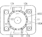
Figure 12 A and 12B represent also within the scope of the present invention a motor.All each electrodes, reaching at epitrochanterian two parts electrode on stator is magnetic symmetry.In this motor, purpose of the present invention is not to be reached by the magnetic asymmetry in the stator pole groups, but the symmetrical magnetic resistance by utmost point group extremely between the asymmetric localization of symmetrical permanent-magnet pole reach.Owing on rotor, also be provided with the symmetrical magnetic resistance utmost point, so the motor shown in Figure 12 A, the 12B also is regarded as belonging to the type i .B in the above-mentioned classification, 1.b.
More specifically, Figure 12 A, motor shown in the 12B comprise the stator 11 with the magnetic resistance electrode 13S that is similar to shown in Figure 1A to 1D.Rotor 12 also is similar to the rotor among Figure 1A to 1D, different is its utmost point 16 its front end and be equipped with in its back-end interpole part 16 ', these interpoles parts have reduced size on circumference.
Each utmost point group comprises the magnetic symmetry permanent-magnet pole 14 of rectangle, they with asymmetric mode or off-center position be arranged among two magnetic resistance utmost point 13S one near.These two permanent-magnet poles 14 are connected on the public actuating mechanism 20 that comprises bar 21.When motor is worked, permanent-magnet pole 14 is fixed on the partial center position of selection, but by bar 21 from Figure 12 A the position shown in the solid line to moving down, permanent-magnet pole 14 will move on to a corresponding partial center position (representing with chain-dotted line at Figure 12 A, 1B) from diagram partial center position on circumference, promptly approach another stator magneto resistance utmost point 13S, so that preferential the turning to oppositely of rotating of rotor.
Therefore, on illustrated attraction rotor-position, the magnetic attraction between the rotor pole of each permanent-magnet pole 14 and its front-turn to-compare the main advantage that accounts for the magnetic attraction between the rotor of this permanent-magnet pole and its back from rotor.When the electric current in the winding coil 15 is turned off and rotor during at shown position, permanent-magnet pole 14 therefore with the rotor clockwise direction move the start position to.
On the start position, the interpole part 16 of two rotor poles, 16 front ends ' will be right after is bordering on and preferably covers mutually with the two stator magneto resistance utmost point 13S of their fronts slightly.When winding coil 15 was energized again, as top described referring to figs. 1A to 1E, therefore these magnetic resistance utmost points can effectively be pushed rotor open on counter-clockwise direction from the start position.
Figure 13 A to 13D is the figure corresponding to Figure 1B, 2B, 3B etc., and is used to further specify the magnetic symmetry of the permanent-magnet pole between a pair of magnetic resistance utmost point on the stator and the notion of magnetic asymmetric localization.The combinations of four difform permanent-magnet poles of these four figure expressions and the stator and the rotor magnetic resistance utmost point, the latter is identical and be similar to combination among Figure 1A and the 1B in all figure.All four figure are illustrated in the rotor magnetic resistance utmost point 16A in the start position, and they align no current in the winding relevant with stator pole groups with permanent-magnet pole 14S (Figure 13 A) or 14A (Figure 13 B to 13D) on magnetic.
On this start position, the power that is acted on the rotor magnetic resistance utmost point 16 by permanent- magnet pole 14S, 14A is zero in a circumferential direction, but depart from any deviation of aligned position in response to rotor pole, the suction between permanent-magnet pole and the rotor pole will form a force of periphery component, try hard to make rotor pole to get back to the start position.
In Figure 13 A, for the purpose of comparison, comprise and express one corresponding to the symmetrical electrode structure shown in the WO 92/12567, permanent-magnet pole 14S fully with the main pole part 16A covering of the rotor magnetic resistance utmost point 16.Figure 13 B-13D represents according to the present invention different stator pole structural, and they are because the asymmetric shape (Figure 13 B-D) of permanent-magnet pole and/or because its asymmetric localization (Figure 13 D) and asymmetric.
In Figure 13 D, the stator pole groups of being made up of utmost point 13S and 14A is because permanent-magnet pole 14 extremely asymmetric and and asymmetric, the result is two asymmetric a little aligned positions of rotor magnetic resistance utmost point 16A between the stator magneto resistance utmost point 13S owing to the asymmetric a little location of this utmost point (stator magneto resistance utmost point 13S takes back).Therefore, when rotor pole 16A when it and right stator magneto resistance utmost point magnetic positions aligning move on to it and permanent-magnet pole 14A magnetic positions aligning it traversing distance greater than it move on to from above-mentioned position it and left magnetic resistance utmost point 13S magnetic positions aligning traversing distance.
Though expression is because magnetic asymmetry on the rotor that utmost point asymmetric localization produces in the accompanying drawings, and individually or combined with the asymmetry of the single utmost point, this asymmetric in stator-rotor pole system also is possible.For example, at Fig. 4 A, in the rotor of 4B to Figure 10 A, 10B shown type, the permanent-magnet pole of a polarity and the permanent-magnet pole of another polarity alternate, the permanent-magnet pole of a polarity can collectively removed from the center between the adjacent permanent-magnet pole of another polarity on arbitrary circumferencial direction, is still at the utmost point of every group of same polarity in extremely and in fact evenly separates.
Among all embodiment in the accompanying drawings, stator and rotor build up by thin electric steel disc, as shown in Fig. 1 D (here for clearly expression, sheet thickness is exaggerative widely).
In forming the sheet part of stator magneto resistance utmost point 13S or 13A, per second stator piece 11A shortens a little, so that outside relative its adjacent sheet of arc-like sheet edge 11B of air gap 17 is radially inclined to one side, sees the lower part of Figure 1A and Fig. 1 D.In other words, only be that per second 11C reaches in the air gap 17, and the end of middle sheet 11A does not reach air gap 17.Similarly the design of the magnetic resistance utmost point can be set at all these wherein stator and rotor are equipped with in the stator and/or rotor of motor of the magnetic resistance utmost point.
Be used for guaranteeing in its lamination attenuation on the pole-face of the magnetic resistance utmost point: the variation of air gap magnetic flux will be proportional to the change of utmost point overlay area between the stator that is produced when the rotor magnetic resistance utmost point turns over the stator magneto resistance utmost point and the rotor magnetic resistance utmost point.In other words, they are used for guaranteeing, as long as the variation of magnetic flux is not kept constant substantially by the magnetic flux density of magnetically saturated restriction utmost point overlay area in each zone of magnetic circuit, so that even as much as possible by the torque of each utmost point interaction generation.
Aspect magnetic, shortening that magnetic resistance utmost point part is per second or reduction make the mean value of saturation flux density on the whole pole-face reduce by 50%, be used for reducing the swing (at the interval of motor change in magnetic flux density on the work period) of stack of laminations magnetic induction, this swing will make the major part of iron loss increase.
Figure 14 A and 14B represent to make the remodeling technology of magnetic resistance utmost point attenuation on the pole-face.This remodeling technology is applicable to the motor that moves under the rising operating frequency, it is not limited on the above-mentioned single-phase motor, is being provided with on the motor of the magnetic resistance utmost point on stator and the rotor and can be used for all usually.For example, the motor of disclosed type can have according to the stator of this remodeling art designs and/or the magnetic resistance utmost point of rotor in WO 90/02437 and WO 92/12567.
Increase the operating frequency that electromotor velocity need increase the electric current of supplying with motor.But increase operating frequency and be accompanied by the increase iron loss.A kind of technology of avoiding iron loss to increase is to use thinner lamination, but has reduced as chankings is thick, will be difficult to maybe can not use automatic producing device.Another technology is to make two in per three to shorten or reduce.But this technology in most of the cases can not make the people satisfied.
Purpose of the present invention also is to provide a kind of magnetic resistance utmost point design, and it is adapted to operate on the frequency of rising, and need not adopt above-mentioned technology.
According to this aspect of the invention, be to reach in the required magnetic resistance utmost point type that reduces at Figure 1A-1D of induction swing when increasing operating frequency by the groove that extends to air gap is set in those laminations, appear at the transversal zone of lamination in the magnetic flux during these grooves have dwindled extremely, help to make the utmost point on pole-face, to become magnetically saturated magnetic flux density thus and descend.
These grooves need evenly to distribute basically on the lamination entire cross section.May adopt form or the employing that the opening of air gap is not promptly led in the hole to communicate with air gap-best form to them via narrow passage.Fat pipe is unfavorable, because they have increased the eddy current in the motor other parts magnetic resistance pole-face.
In Figure 14 A and 14B, express the remodeling that is used for the magnetic resistance of motor stator shown in Figure 1A-1D utmost point to demonstration, promptly be used for the stator magneto resistance utmost point on the stator pole groups right side.Figure 14 A represents the magnetic resistance utmost point part after a lamination 11A shortens, and Figure 14 B represents the whole length magnetic resistance utmost point part of adjacent laminates 11C.In the zone near air gap 17, this part is provided with the groove 11D of three long hole shape, and they have the closed contour line and come thus and are communicated with curved edge 11E towards air gap.These three grooves are along evenly distributing on the length of curved edge.
When design lamination trough of belt part, following empirical equation will help: Δ B
2=Δ B
1(f
1/ f
2)
1/1.2In the formula, Δ B and f represent the oscillating quantity and the operating frequency of magnetic induction respectively, subscript 1 and two kinds of different operating states of 2 expressions.Can be understood at once that by this formula the increase operating frequency does not change iron loss and then requires to reduce the magnetic induction oscillating quantity, this value is less than the increase that directly is proportional to operating frequency.For example, during the operating frequency twice for guaranteeing that the constant needs of iron loss make the magnetic induction oscillating quantity drop to 56% of preceding value.When increasing frequency, can become and adjust iron loss and copper loss, so that they become near equaling to produce the optimum value of torque.Therefore, magnetic flux density can select to be higher than the magnetic flux density when not changing iron loss.
Though the above-mentioned groove of establishing has reduced saturation flux density on the magnetic resistance pole-face, will reach the actual increase of air gap power for the motor of same size, because the increase of electromotor velocity is greater than the essential decline of motor torque in iron plate.Certainly, the magnetic resistance utmost point groove of establishing partly according to above-mentioned principle lamination can be applicable to have as reach the motor of the magnetic resistance utmost point part in the air gap among Fig. 1 D and the 14B for all sheets shown in the lamination 11C.If desired, can establish different grooves for adjacent lamination.
Alternative embodiment
Following replacement motor example is made into and can be configured as rotation or linear motor by the utmost point assembling of establishing winding.
Turning motor can have:
1. the air gap surface of cylindrical, conical, dish type etc. can be the surface of the Any shape that can retouch out around the bus of fixed axis rotation in principle.
2. external rotor.
3. the difference of stator poles and rotor number of poles can be any number, for example under the situation of sectionalized stator.
4. in the motor that is provided with cylinder air-gap surface and internal rotor, a plurality of utmost point groups can be set and make them be connected (embodiment as shown in the drawing) in the same plane together by electric steel lamination.Motor can be made up of a plurality of this " motor boards " along common shaft.
These dishes can be designed to not have closed magnetic circuit alone in addition, but connect by the auxiliary magnetic flux path that leads.The example of this design can be found in WO 90/02437." motor board " can the public coil of two " motor boards " comes excitatory by for example being used for.
5. for the motor of axial magnetic flux connection between " motor board ", winding can be formed (this example of structure is indicated among the WO 90/02437) by the cylindrical coil around rotating shaft.For example in the case, rotating part can comprise it being static utmost point type originally, and vice versa.
6. wherein stator does not have the motor that the magnetic resistance utmost point and permanent-magnet pole also only have a kind of utmost point type thus simultaneously, can be within the scope of the invention by stator poles and rotor pole switch are retrofited.The example of this situation is the motor among Fig. 5 A, 5B, 8A, 8B and 10A, the 10B.In these motor, the extremely available permanent-magnet pole corresponding to permanent-magnet pole on the rotor of the magnetic resistance on the stator replaces, and epitrochanterian permanent-magnet pole can use the magnetic resistance corresponding to the magnetic resistance utmost point on the stator extremely to replace.The remodeling of motor among Figure 11 A, 11B presentation graphs 8A, the 8B.
7. the shape of the utmost point and/or distribution in the motor for example can be selected in this wise to the magnetic resistance utmost point, so that the noise and the vibration that are produced by the change of magnetic force between stator and the rotor reduce as far as possible.The example of this types of known measure is crooked utmost point edge or along the uneven distribution a little of the rotor flank utmost point, or between the pole span of stator pole groups and rotor pole group some difference is arranged.Various measures use also capable of being combined.
8. be the magnetic resistance number of poles order of two or other even number is arranged and not have in the motor of the stator permanent magnet utmost point in the every utmost point group of stator, the soft magnetism stator yoke part of extending at utmost point group mid portion can be removed in the illustrated embodiment, and can not influence the magnetic action of motor.Described stator yoke can be replaced by non magnetic shelf device as the mechanical function of shelf.
9. be appreciated that the coil that being used to shown in Fig. 1 to 12 magnetize utmost point group can differently arrange,, or use coil shown in Figure 11 A for example with transformer or coil around yoke between utmost point group.Stator yoke also can be separated, and can use the coil of pre-coiling thus.Also can in miniature motor, economy advantageously use the single yoke that is provided with two cross sections to replace two yokes that the two poles of the earth group is connected together, and on this list yoke, be wound with single coil.This being arranged in small-sized non salient pole motor and the direct current machine is known.
10. in order in motor, only to use single electronic switching device that unipolar current impulse is provided, magnetic field energy can be turned back to the DC power supply by means of the feedback winding that is listed in the work winding, described in WO 90/02437.
Claims (30)
1. self-starting brushless electric motor comprises:
Have to separate first motor portion (11) that relation is arranged in a plurality of utmost point groups on first utmost point row (S);
Have to separate second motor portion (12) that relation is arranged in a plurality of utmost points on second utmost point row (R);
Support the supporting arrangement of first motor portion and second motor portion, be used to make first utmost point row to arrange relative motion in the face of second utmost point by air gap (17);
First and second utmost point row (S, R) constitute the electrode systems that comprises first and second polar form, the utmost point of first polar form is the magnetic resistance utmost point, the utmost point of second polar form is a permanent-magnet pole, these permanent-magnet pole crosscut air gap ground polarization, this electrode systems presents the magnetic asymmetry, and the preferential direction of relative movement of described motor portion is provided when winding system encourages, and
Winding system on first motor portion (15), it comprises the winding coil of arranging relatively with each utmost point group, to produce the magnetic field that makes first and second utmost points row's utmost point intersecting chain by utmost point group when coil is energized;
It is characterized in that:
At least one utmost point group of first utmost point row (S) comprises first and second polar form simultaneously, and presents the magnetic asymmetry, and second utmost point row's (R) the utmost point (16,16A, 18AN, 18AS, 18SN, 18SS) all is identical polar form, and asymmetric.
2. according to the motor of claim 1, it is characterized in that: described at least one utmost point group among first utmost point row (S) has at least one asymmetric magnetic resistance utmost point (13S), and second utmost point group (R) comprises a plurality of asymmetric magnetic resistance utmost points (16A) that evenly separate basically.
3. according to the motor of claim 1, it is characterized in that: second utmost point row (R) has a plurality of asymmetric magnetic resistance utmost points (13S) or a plurality of asymmetric permanent-magnet pole (18AS, 18AN).
4. according to the motor of claim 2, it is characterized in that: the magnetic resistance utmost point (13S) that at least one utmost point group of first utmost point row (R) has a symmetry, an asymmetric magnetic resistance utmost point (13A) and the asymmetric permanent-magnet pole (18AS, 18AN) between these two magnetic resistance utmost points; And second utmost point row (R) comprises a plurality of asymmetric magnetic resistance utmost points (16A) that substantially evenly separate.
5. according to the motor of claim 1, it is characterized in that: at least one utmost point group of first utmost point row (S) has the magnetic resistance utmost point (16S) of two symmetries and the asymmetric permanent-magnet pole (18AS, 18AN) between these magnetic resistance utmost points; A plurality of magnetic resistance utmost points (16A) that evenly separate are basically drawn together in second utmost point package.
6. according to the motor of claim 1, it is characterized in that: the asymmetric utmost point (13A of first motor portion (11) and second motor portion (12), 14A, 18AN, 18AS) comprise main pole part and interpole part (13 ', 14 ', 18 '), the latter partly goes up in the preferential direction of motion of corresponding motor portion from main pole and stretches out.
7. according to the motor of claim 6, it is characterized in that: interpole part (13 ', 14 ', 18 ') have (S, R) length measured along utmost point row, when any two utmost points of two motor portion (11,12) each other during the magnetic alignment, the interpole of the asymmetric utmost point of at least one magnetic on the motor portion (11,12) part extends near the consecutive roots on another motor portion (12,11) at least, and preferably covers described consecutive roots a little.
8. according to the motor of claim 1, it is characterized in that: first utmost point row's (S) utmost point group is identical.
9. self-starting brushless electric motor comprises:
Have to separate first motor portion (11) that relation is arranged in a plurality of utmost point groups on first utmost point row (S);
Have to separate second motor portion (12) that relation is arranged in a plurality of utmost points on second utmost point row (R);
Support the supporting arrangement of first motor portion and second motor portion, be used to make first utmost point row to arrange relative motion in the face of second utmost point by air gap (17);
First and second utmost point row (S, R) constitute the electrode systems that comprises first and second polar form, the utmost point of first polar form is the magnetic resistance utmost point, the utmost point of second polar form is a permanent-magnet pole, these permanent-magnet pole crosscut air gap ground polarization, this electrode systems presents the magnetic asymmetry, and the preferential direction of relative movement of described motor portion is provided when winding system encourages, and
Winding system on first motor portion (15), it comprises the winding coil of arranging relatively with each utmost point group, to produce the magnetic field that makes first and second utmost points row's utmost point intersecting chain by utmost point group when coil is energized;
It is characterized in that:
At least one utmost point group of first utmost point row (S) comprises a pair of magnetic resistance utmost point, this to magnetic resistance extremely at least one (13A) be asymmetric, one in asymmetric permanent-magnet pole (14A) between (13A, 13S) between this magnetic resistance utmost point, and second utmost point row (R) has a plurality of symmetrical permanent-magnet poles that evenly separate basically (18SN, 18SS).
10. according to the motor of claim 9, it is characterized in that: the magnetic resistance utmost point and an asymmetric magnetic resistance utmost point (13A) that described at least one utmost point group of first utmost point row (S) has a symmetry.
11. the motor according to claim 1 is characterized in that: described at least one utmost point group of first utmost point row (S) has a symmetrical magnetic resistance utmost point (13S) and a symmetrical permanent-magnet pole (14S).
12. the motor according to claim 11 is characterized in that: second utmost point row (R) has a plurality of asymmetric magnetic resistance utmost points (16A) that evenly separate basically or a plurality of evenly spaced basically asymmetric permanent-magnet pole (18AN, 18AS).
13. the motor according to claim 11 is characterized in that: described at least one utmost point group of first utmost point row (S) also has at least one asymmetric magnetic resistance utmost point (13A), and the permanent-magnet pole of this utmost point group (14S) is arranged between the magnetic resistance utmost point (13A, 13S).
14. motor according to claim 9, it is characterized in that: the asymmetric utmost point (13A of first motor portion (11) and second motor portion (12), 14A, 18AN, 18AS) comprise main pole part and interpole part (13 ', 14 ', 18 '), the latter partly goes up in the preferential direction of motion of corresponding motor portion from main pole and stretches out.
15. motor according to claim 14, it is characterized in that: interpole part (13 ', 14 ', 18 ') have along utmost point row (S, R) length measured and be, when any two utmost points of two motor portion (11,12) each other during the magnetic alignment, the interpole of the asymmetric utmost point of at least one magnetic on the motor portion (11,12) part extends near the consecutive roots on another motor portion (12,11) at least, and preferably covers described consecutive roots a little.
16. the motor according to claim 9 is characterized in that: first utmost point row's (S) utmost point group is identical.
17. a self-starting brushless electric motor comprises:
Have to separate first motor portion (11) that relation is arranged in a plurality of utmost point groups on first utmost point row (S);
Have to separate second motor portion (12) that relation is arranged in a plurality of utmost points on second utmost point row (R);
Support the supporting arrangement of first motor portion and second motor portion, be used to make first utmost point row to arrange relative motion in the face of second utmost point by air gap (17);
First and second utmost point row (S, R) constitute the electrode systems that comprises first and second polar form, the utmost point of first polar form is the magnetic resistance utmost point, the utmost point of second polar form is a permanent-magnet pole, these permanent-magnet pole crosscut air gap ground polarization, this electrode systems presents the magnetic asymmetry, and the preferential direction of relative movement of described motor portion is provided when winding system encourages, and
Winding system on first motor portion (15), it comprises the winding coil of arranging relatively with each utmost point group, to produce the magnetic field that makes first and second utmost points row's utmost point intersecting chain by utmost point group when coil is energized;
It is characterized in that: first utmost point row (S) only comprises the asymmetric magnetic resistance utmost point (13A), reaches the permanent-magnet pole (18AN, 18AS, 18SN, 18SS) that second utmost point row (R) comprises a plurality of alter polarities, and the utmost point of identical polar is evenly arranged basically separatedly.
18. the motor according to claim 17 is characterized in that: second utmost point row (R) includes only asymmetric permanent-magnet pole (18AN, 18AS).
19. motor according to claim 17, it is characterized in that: the asymmetric utmost point (13A of first motor portion (11) and second motor portion (12), 14A, 18AN, 18AS) comprise main pole part and interpole part (13 ', 14 ', 18 '), the latter partly goes up in the preferential direction of motion of corresponding motor portion from main pole and stretches out.
20. motor according to claim 19, it is characterized in that: interpole part (13 ', 14 ', 18 ') have (S, R) length measured along utmost point row, when any two utmost points of two motor portion (11,12) each other during the magnetic alignment, the interpole of the asymmetric utmost point of at least one magnetic on the motor portion (11,12) part extends near the consecutive roots on another motor portion (12,11) at least, and preferably covers described consecutive roots a little.
21. the motor according to claim 17 is characterized in that: first utmost point row's (S) utmost point group is identical.
22. a self-starting brushless electric motor comprises:
Have to separate first motor portion (11) that relation is arranged in a plurality of utmost point groups on first utmost point row (S);
Have to separate second motor portion (12) that relation is arranged in a plurality of utmost points on second utmost point row (R);
Support the supporting arrangement of first motor portion and second motor portion, be used to make first utmost point row to arrange relative motion in the face of second utmost point by air gap (17);
First and second utmost point row (S, R) constitute the electrode systems that comprises first and second polar form, the utmost point of first polar form is the magnetic resistance utmost point, the utmost point of second polar form is a permanent-magnet pole, these permanent-magnet pole crosscut air gap ground polarization, this electrode systems presents the magnetic asymmetry, and the preferential direction of relative movement of described motor portion is provided when winding system encourages, and
Winding system on first motor portion (15), it comprises the winding coil of arranging relatively with each utmost point group, to produce the magnetic field that makes first and second utmost points row's utmost point intersecting chain by utmost point group when coil is energized;
It is characterized in that: first utmost point row only comprise permanent-magnet pole (14AN, 14AS), at least one utmost point group of first utmost point row (S) comprises a pair of asymmetric permanent-magnet pole of polarization in the opposite direction; And second utmost point row (R) comprises a plurality of asymmetric magnetic resistance utmost points (16A) that evenly separate basically.
23. the motor according to claim 22 is characterized in that: this utmost point group comprises that at least one is with respect to an adjacent utmost point or the additional asymmetric permanent-magnet pole (14AN, 14AS) of a plurality of extremely opposite polarization.
24. the motor according to claim 1 is characterized in that: at least one utmost point group of first utmost point row (S) comprises a permanent-magnet pole (14) that is arranged in asymmetric position, and second utmost point row (R) comprises a plurality of magnetic resistance utmost points (16) that evenly separate basically.
25. the motor according to claim 24 is characterized in that: described utmost point group comprises a pair of magnetic resistance utmost point (13S), and this permanent-magnet pole (14) is arranged between the magnetic resistance utmost point (13S) the asymmetric position with respect to this magnetic resistance utmost point.
26. the motor according to claim 25 is characterized in that: the permanent-magnet pole (14) and the magnetic resistance utmost point (13S) are symmetrical; And permanent-magnet pole (14) is the corresponding asymmetric position that can move on to line of symmetry (L) opposite side between the magnetic resistance utmost point (13S) along this utmost point row (R) from described asymmetric position; And second utmost point row's the magnetic resistance utmost point (16) comprises that main pole partly reaches the interpole part (16 ') on the every side of main pole part.
27. motor according to claim 22, it is characterized in that: the asymmetric utmost point (13A of first motor portion (11) and second motor portion (12), 14A, 18AN, 18AS) comprise main pole part and interpole part (13 ', 14 ', 18 '), this interpole part partly goes up in the preferential direction of motion of corresponding motor portion from main pole stretches out.
28. motor according to claim 27, it is characterized in that: interpole part (13 ', 14 ', 18 ') have (S, R) length measured along utmost point row, when any two utmost points of two motor portion (11,12) each other during the magnetic alignment, the interpole of the asymmetric utmost point of at least one magnetic on the motor portion (11,12) part extends near the consecutive roots on another motor portion (12,11) at least, and preferably covers described consecutive roots a little.
29. the motor according to claim 22 is characterized in that: first utmost point row's (S) utmost point group is identical.
30. each motor in requiring according to aforesaid right, it is characterized in that: this motor is a turning motor; And first utmost point row (S) comprises the utmost point group that at least one pair of is radially relative.
Applications Claiming Priority (7)
| Application Number | Priority Date | Filing Date | Title |
|---|---|---|---|
| SE95019816 | 1995-05-30 | ||
| SE9501981-6 | 1995-05-30 | ||
| SE9501981A SE9501981D0 (en) | 1995-05-30 | 1995-05-30 | Self-starting brushless electric motor |
| DE19520052.7 | 1995-05-31 | ||
| DE19520054.3 | 1995-05-31 | ||
| DE19520052 | 1995-05-31 | ||
| DE19520054 | 1995-05-31 |
Publications (2)
| Publication Number | Publication Date |
|---|---|
| CN1191640A CN1191640A (en) | 1998-08-26 |
| CN1077347C true CN1077347C (en) | 2002-01-02 |
Family
ID=27215163
Family Applications (1)
| Application Number | Title | Priority Date | Filing Date |
|---|---|---|---|
| CN96195652A Expired - Lifetime CN1077347C (en) | 1995-05-30 | 1996-05-30 | Self-starting brushless electric motor |
Country Status (7)
| Country | Link |
|---|---|
| US (2) | US6204587B1 (en) |
| EP (2) | EP0829128B1 (en) |
| JP (2) | JP3833254B2 (en) |
| CN (1) | CN1077347C (en) |
| AT (1) | ATE245867T1 (en) |
| DE (1) | DE69629192T2 (en) |
| WO (1) | WO1996038903A1 (en) |
Families Citing this family (48)
| Publication number | Priority date | Publication date | Assignee | Title |
|---|---|---|---|---|
| EP0829128B1 (en) * | 1995-05-30 | 2003-07-23 | Vilmos TÖRÖK | A self-starting brushless electric motor |
| SE516498C2 (en) * | 1996-05-30 | 2002-01-22 | Vilmos Toeroek | Self-starting brushless electric motor |
| SE516499C2 (en) * | 1996-05-30 | 2002-01-22 | Vilmos Toeroek | Self-starting brushless electric motor |
| GB9615950D0 (en) * | 1996-07-30 | 1996-09-11 | Univ Warwick | Variable reluctance machines |
| DE19904469A1 (en) * | 1999-02-04 | 2000-08-10 | Bosch Gmbh Robert | Rotary actuator and rotary switch |
| GB9915370D0 (en) * | 1999-07-02 | 1999-09-01 | Black & Decker Inc | Electrical machines |
| US7058291B2 (en) | 2000-01-07 | 2006-06-06 | Black & Decker Inc. | Brushless DC motor |
| US6538403B2 (en) | 2000-01-07 | 2003-03-25 | Black & Decker Inc. | Brushless DC motor sensor control system and method |
| US6975050B2 (en) | 2000-01-07 | 2005-12-13 | Black & Decker Inc. | Brushless DC motor |
| DE10135019A1 (en) * | 2001-07-18 | 2003-01-30 | Bosch Gmbh Robert | Electric motor with permanent magnet excitation |
| DE10147310B4 (en) * | 2001-09-26 | 2004-06-17 | Vacuumschmelze Gmbh & Co. Kg | Cup-shaped magnet |
| US6710502B2 (en) * | 2002-02-07 | 2004-03-23 | Wavecrest Laboratories, Llc | Rotary electric motor having at least three axially aligned stator poles and/or rotor poles |
| US6717323B1 (en) * | 2002-06-04 | 2004-04-06 | Wavecrest Laboratories, Llc | Rotary electric motor having a plurality of skewed stator poles and/or rotor poles |
| US6727629B1 (en) * | 2002-06-04 | 2004-04-27 | Wavecrest Laboratories, Llc | Rotary electric motor having a plurality of shifted stator poles and/or rotor poles |
| GB0215849D0 (en) * | 2002-07-09 | 2002-08-14 | Switched Reluctance Drives Ltd | Starting of switched reluctance generators |
| FR2847087B1 (en) * | 2002-08-14 | 2014-04-11 | Valeo Equip Electr Moteur | DOUBLE EXCITATION ROTATING ELECTRIC MACHINE ALLOWING MODULAR DEFLUX |
| US20040061387A1 (en) * | 2002-09-27 | 2004-04-01 | Harmonic Drive, Inc. | Magnetically actuated commutator |
| US6906443B2 (en) * | 2003-04-21 | 2005-06-14 | Eaton Corporation | Brushless DC motor with stepped skewed rotor |
| US7237748B2 (en) * | 2003-12-15 | 2007-07-03 | Delos Aerospace, Llc | Landing gear method and apparatus for braking and maneuvering |
| JP4619040B2 (en) * | 2004-05-14 | 2011-01-26 | アイシン・エィ・ダブリュ株式会社 | Electric drive control device, electric drive control method, and program |
| TWI249898B (en) * | 2004-08-27 | 2006-02-21 | Delta Electronics Inc | Brushless DC motor and driver used therein |
| CN1832305B (en) * | 2005-03-08 | 2010-09-01 | 可斯塔·佩龙尼斯 | Brushless DC fan |
| US20070132330A1 (en) * | 2005-12-12 | 2007-06-14 | Fei Renyan W | Fan assemblies employing LSPM motors and LSPM motors having improved synchronization |
| DE102006034578A1 (en) * | 2006-07-26 | 2008-01-31 | Siemens Ag | Electrical machine for use in e.g. roller mill drive, has air gap provided between stator and rotor, where air gap has subareas with different radial expansions arranged side by side in axial middle section |
| US8901798B2 (en) * | 2007-05-31 | 2014-12-02 | Regal Beloit America, Inc. | Switched reluctance machines with minimum stator core |
| AU2008291655B2 (en) * | 2007-08-24 | 2012-12-06 | Sunco Investments Ltd. | Multistage variable reluctance motor/generator |
| EP2454804B1 (en) * | 2009-07-16 | 2020-11-18 | OneSubsea IP UK Limited | Electric motor including a position holding device |
| DE102009037114A1 (en) | 2009-07-31 | 2011-02-03 | C. & E. Fein Gmbh | Series motor with permanent magnet |
| ITPN20110015A1 (en) * | 2011-03-11 | 2012-09-12 | Mate S A S Di Furlan Massimo & C | BRUSHLESS ELECTRIC MOTOR WITH PERMANENT MAGNET OF SINGLE-PHASE TYPE |
| CN102299607B (en) * | 2011-08-25 | 2013-02-13 | 哈尔滨工业大学 | Transverse magnetic flux linear reluctance motor with offset permanent magnet |
| RU2524144C2 (en) * | 2012-03-19 | 2014-07-27 | Федеральное государственное автономное образовательное учреждение высшего профессионального образования "Уральский федеральный университет имени первого Президента России Б.Н. Ельцина" | Single-phase electrical machine |
| JP2016000960A (en) * | 2012-09-07 | 2016-01-07 | 三菱重工業株式会社 | Motor compressor for transport machine |
| US9719607B2 (en) * | 2012-09-10 | 2017-08-01 | Cameron International Corporation | Magnetic holding brake and actuator with a magnetic holding brake |
| US9293952B2 (en) * | 2012-11-05 | 2016-03-22 | Foster-Miller, Inc. | Wound field flux switching machine with sinusoidal back electromotive force |
| JP2014204491A (en) * | 2013-04-02 | 2014-10-27 | 本田技研工業株式会社 | Brushless direct-current motor |
| CN103997178A (en) * | 2014-05-19 | 2014-08-20 | 刘忠涛 | Permanent magnet magnetic resistance energy-saving motor |
| JP6062900B2 (en) * | 2014-09-15 | 2017-01-18 | トヨタ自動車株式会社 | Manufacturing method of rotor |
| US10107275B2 (en) * | 2014-12-01 | 2018-10-23 | Sheng-Lian Lin | Linear motor and compressor having the same |
| US10075051B2 (en) | 2015-03-16 | 2018-09-11 | Foster-Miller, Inc. | Series-wound heteropolar inductor motor |
| US9825510B2 (en) * | 2016-04-13 | 2017-11-21 | Hamilton Sundstrand Corporation | Variable gap electrical machines |
| KR101899508B1 (en) * | 2016-10-20 | 2018-09-19 | (주)리큅 | Switched Reluctance Motor with Improved Rotor |
| ES2666212B1 (en) * | 2016-10-26 | 2019-03-19 | Univ Catalunya Politecnica | SWITCHED AXIAL FLOW RELUCTANCE MACHINE AND ELECTRIC VEHICLE COMPRISING THE MACHINE |
| KR101893261B1 (en) * | 2016-11-04 | 2018-08-30 | 경성대학교 산학협력단 | Hybrid single-phase SRM with non-uniform air gap |
| KR101893262B1 (en) * | 2016-11-04 | 2018-08-29 | 경성대학교 산학협력단 | Hybrid single-phase SRM with combined air gap |
| KR101893289B1 (en) * | 2017-02-07 | 2018-08-29 | 경성대학교 산학협력단 | The Motor that prevent permanent magnet from coming off |
| US10840015B2 (en) * | 2017-07-26 | 2020-11-17 | Hitachi Industrial Products, Ltd. | Laminated core rotatable transformer |
| US10965176B2 (en) | 2019-01-15 | 2021-03-30 | Mcmillan Electric Company | Electric motors with pole biasing |
| CN114421656B (en) * | 2021-12-31 | 2023-09-29 | 歌尔股份有限公司 | Rotating device, force feedback device and electronic equipment |
Citations (2)
| Publication number | Priority date | Publication date | Assignee | Title |
|---|---|---|---|---|
| WO1990002437A1 (en) * | 1988-08-25 | 1990-03-08 | Toeroek Vilmos | An electric motor |
| WO1992012567A1 (en) * | 1990-12-28 | 1992-07-23 | Toeroek Vilmos | Electric motor |
Family Cites Families (15)
| Publication number | Priority date | Publication date | Assignee | Title |
|---|---|---|---|---|
| JPS5543953A (en) * | 1978-09-20 | 1980-03-28 | Rhythm Watch Co Ltd | Miniature motor for watch |
| US4438362A (en) * | 1982-08-19 | 1984-03-20 | Rotron, Incorporated | Self-starting, direct current motor with permanent magnets of varied magnetic strength |
| US4583015A (en) * | 1983-08-20 | 1986-04-15 | Pioneer Electronic Corporation | Single-phase brushless motor with multisector stator armature poles having different cross-sections |
| SE442368B (en) * | 1983-12-21 | 1985-12-16 | Ems Electronic Motor Systems | COMMUTION TYPE RELUCTION ENGINE |
| SE459833B (en) * | 1987-12-09 | 1989-08-07 | Astra Tech Ab | ROTATING ELECTRIC MACHINE |
| US5294856A (en) * | 1990-04-30 | 1994-03-15 | Emerson Electric Co. | Shifted pole single phase variable reluctance motor |
| GB9225846D0 (en) * | 1992-12-10 | 1993-02-03 | Switched Reluctance Drives Ltd | Further improvements in electric machines |
| GB9414584D0 (en) | 1994-07-19 | 1994-09-07 | Smithkline Beecham Plc | Package |
| EP0829128B1 (en) * | 1995-05-30 | 2003-07-23 | Vilmos TÖRÖK | A self-starting brushless electric motor |
| DE19633209A1 (en) * | 1995-08-28 | 1997-03-06 | Papst Motoren Gmbh & Co Kg | Reducing reluctance moment or cogging of electric motor |
| SE516498C2 (en) * | 1996-05-30 | 2002-01-22 | Vilmos Toeroek | Self-starting brushless electric motor |
| SE516499C2 (en) * | 1996-05-30 | 2002-01-22 | Vilmos Toeroek | Self-starting brushless electric motor |
| JPH1032967A (en) * | 1996-07-15 | 1998-02-03 | Tsujikawa Keiko | Torque developing device |
| US6232693B1 (en) * | 1997-05-13 | 2001-05-15 | Emerson Electric Co. | Switched reluctance motor having stator inserts for noise reduction, magnet positioning, and coil retention |
| JP3450710B2 (en) * | 1997-10-24 | 2003-09-29 | オークマ株式会社 | Switch reluctance motor |
-
1996
- 1996-05-30 EP EP96916422A patent/EP0829128B1/en not_active Expired - Lifetime
- 1996-05-30 CN CN96195652A patent/CN1077347C/en not_active Expired - Lifetime
- 1996-05-30 DE DE69629192T patent/DE69629192T2/en not_active Expired - Lifetime
- 1996-05-30 AT AT96916422T patent/ATE245867T1/en active
- 1996-05-30 JP JP53640896A patent/JP3833254B2/en not_active Expired - Lifetime
- 1996-05-30 WO PCT/SE1996/000704 patent/WO1996038903A1/en active IP Right Grant
- 1996-05-30 EP EP03016486A patent/EP1363384A3/en not_active Withdrawn
- 1996-05-30 US US08/973,185 patent/US6204587B1/en not_active Expired - Lifetime
-
2001
- 2001-01-03 US US09/752,512 patent/US6512318B2/en not_active Expired - Lifetime
-
2006
- 2006-01-25 JP JP2006016762A patent/JP3921494B2/en not_active Expired - Lifetime
Patent Citations (2)
| Publication number | Priority date | Publication date | Assignee | Title |
|---|---|---|---|---|
| WO1990002437A1 (en) * | 1988-08-25 | 1990-03-08 | Toeroek Vilmos | An electric motor |
| WO1992012567A1 (en) * | 1990-12-28 | 1992-07-23 | Toeroek Vilmos | Electric motor |
Also Published As
| Publication number | Publication date |
|---|---|
| WO1996038903A1 (en) | 1996-12-05 |
| EP1363384A2 (en) | 2003-11-19 |
| JP2006174699A (en) | 2006-06-29 |
| JPH11506299A (en) | 1999-06-02 |
| EP1363384A3 (en) | 2003-12-17 |
| US6204587B1 (en) | 2001-03-20 |
| JP3921494B2 (en) | 2007-05-30 |
| DE69629192T2 (en) | 2004-05-27 |
| ATE245867T1 (en) | 2003-08-15 |
| US6512318B2 (en) | 2003-01-28 |
| EP0829128B1 (en) | 2003-07-23 |
| JP3833254B2 (en) | 2006-10-11 |
| US20020047447A1 (en) | 2002-04-25 |
| CN1191640A (en) | 1998-08-26 |
| DE69629192D1 (en) | 2003-08-28 |
| EP0829128A1 (en) | 1998-03-18 |
Similar Documents
| Publication | Publication Date | Title |
|---|---|---|
| CN1077347C (en) | Self-starting brushless electric motor | |
| CN1086858C (en) | Self-starting brushless electric machine | |
| CN1064786C (en) | DC brushless motor and control unit | |
| US8397369B2 (en) | Flux focusing arrangement for permanent magnets, methods of fabricating such arrangements, and machines including such arrangements | |
| CN1215634C (en) | Brushless motor | |
| CN1537354A (en) | Brushless motor using vernier structure | |
| CN1870399A (en) | Stepping motor for generating vibration | |
| CN1799176A (en) | Electric motor | |
| CN1747292A (en) | Vibrating motor and portable terminal apparatus using same | |
| CN101064464A (en) | Hybrid permanent magnet type electric rotating machine and manufacturing method thereof | |
| US20110001386A1 (en) | Motor and electronic apparatus using the same | |
| CN1330807A (en) | System for controlling rotary device | |
| CN1606220A (en) | Multi-polar rotary machine | |
| CN1518188A (en) | Reluctance motor and magnet of stator for reluctance motor | |
| JP2003174761A5 (en) | ||
| CN1905318A (en) | Driving apparatus | |
| AU2008298263B2 (en) | Axial-gap rotary electric machine | |
| CN1846342A (en) | Electromagnetic actuator | |
| JP2019201441A (en) | Electric motor and manufacturing method for the same | |
| JP2006240793A (en) | Component transfer device | |
| JP2006223033A (en) | R-fe-b radial anisotropic sintered ring magnet and voice coil motor | |
| CN1029343C (en) | Program sample introduction method | |
| CN1747290A (en) | Motor and devive using this | |
| CN1732608A (en) | Linear actuator | |
| JP5313627B2 (en) | Brush-fed hybrid excitation motor and driving method of brush-fed hybrid excitation motor |
Legal Events
| Date | Code | Title | Description |
|---|---|---|---|
| C06 | Publication | ||
| PB01 | Publication | ||
| C10 | Entry into substantive examination | ||
| SE01 | Entry into force of request for substantive examination | ||
| C14 | Grant of patent or utility model | ||
| GR01 | Patent grant | ||
| CX01 | Expiry of patent term |
Granted publication date: 20020102 |
|
| EXPY | Termination of patent right or utility model |