CN107666962B - Device and method for sample analysis - Google Patents
Device and method for sample analysis Download PDFInfo
- Publication number
- CN107666962B CN107666962B CN201680032095.2A CN201680032095A CN107666962B CN 107666962 B CN107666962 B CN 107666962B CN 201680032095 A CN201680032095 A CN 201680032095A CN 107666962 B CN107666962 B CN 107666962B
- Authority
- CN
- China
- Prior art keywords
- substrate
- analyte
- array
- droplet
- wells
- Prior art date
- Legal status (The legal status is an assumption and is not a legal conclusion. Google has not performed a legal analysis and makes no representation as to the accuracy of the status listed.)
- Active
Links
Images


Classifications
-
- B—PERFORMING OPERATIONS; TRANSPORTING
- B01—PHYSICAL OR CHEMICAL PROCESSES OR APPARATUS IN GENERAL
- B01L—CHEMICAL OR PHYSICAL LABORATORY APPARATUS FOR GENERAL USE
- B01L3/00—Containers or dishes for laboratory use, e.g. laboratory glassware; Droppers
- B01L3/50—Containers for the purpose of retaining a material to be analysed, e.g. test tubes
- B01L3/502—Containers for the purpose of retaining a material to be analysed, e.g. test tubes with fluid transport, e.g. in multi-compartment structures
- B01L3/5027—Containers for the purpose of retaining a material to be analysed, e.g. test tubes with fluid transport, e.g. in multi-compartment structures by integrated microfluidic structures, i.e. dimensions of channels and chambers are such that surface tension forces are important, e.g. lab-on-a-chip
- B01L3/502769—Containers for the purpose of retaining a material to be analysed, e.g. test tubes with fluid transport, e.g. in multi-compartment structures by integrated microfluidic structures, i.e. dimensions of channels and chambers are such that surface tension forces are important, e.g. lab-on-a-chip characterised by multiphase flow arrangements
- B01L3/502784—Containers for the purpose of retaining a material to be analysed, e.g. test tubes with fluid transport, e.g. in multi-compartment structures by integrated microfluidic structures, i.e. dimensions of channels and chambers are such that surface tension forces are important, e.g. lab-on-a-chip characterised by multiphase flow arrangements specially adapted for droplet or plug flow, e.g. digital microfluidics
-
- B—PERFORMING OPERATIONS; TRANSPORTING
- B01—PHYSICAL OR CHEMICAL PROCESSES OR APPARATUS IN GENERAL
- B01L—CHEMICAL OR PHYSICAL LABORATORY APPARATUS FOR GENERAL USE
- B01L3/00—Containers or dishes for laboratory use, e.g. laboratory glassware; Droppers
-
- B—PERFORMING OPERATIONS; TRANSPORTING
- B01—PHYSICAL OR CHEMICAL PROCESSES OR APPARATUS IN GENERAL
- B01L—CHEMICAL OR PHYSICAL LABORATORY APPARATUS FOR GENERAL USE
- B01L3/00—Containers or dishes for laboratory use, e.g. laboratory glassware; Droppers
- B01L3/50—Containers for the purpose of retaining a material to be analysed, e.g. test tubes
- B01L3/502—Containers for the purpose of retaining a material to be analysed, e.g. test tubes with fluid transport, e.g. in multi-compartment structures
- B01L3/5027—Containers for the purpose of retaining a material to be analysed, e.g. test tubes with fluid transport, e.g. in multi-compartment structures by integrated microfluidic structures, i.e. dimensions of channels and chambers are such that surface tension forces are important, e.g. lab-on-a-chip
- B01L3/502707—Containers for the purpose of retaining a material to be analysed, e.g. test tubes with fluid transport, e.g. in multi-compartment structures by integrated microfluidic structures, i.e. dimensions of channels and chambers are such that surface tension forces are important, e.g. lab-on-a-chip characterised by the manufacture of the container or its components
-
- B—PERFORMING OPERATIONS; TRANSPORTING
- B01—PHYSICAL OR CHEMICAL PROCESSES OR APPARATUS IN GENERAL
- B01L—CHEMICAL OR PHYSICAL LABORATORY APPARATUS FOR GENERAL USE
- B01L3/00—Containers or dishes for laboratory use, e.g. laboratory glassware; Droppers
- B01L3/50—Containers for the purpose of retaining a material to be analysed, e.g. test tubes
- B01L3/502—Containers for the purpose of retaining a material to be analysed, e.g. test tubes with fluid transport, e.g. in multi-compartment structures
- B01L3/5027—Containers for the purpose of retaining a material to be analysed, e.g. test tubes with fluid transport, e.g. in multi-compartment structures by integrated microfluidic structures, i.e. dimensions of channels and chambers are such that surface tension forces are important, e.g. lab-on-a-chip
- B01L3/502715—Containers for the purpose of retaining a material to be analysed, e.g. test tubes with fluid transport, e.g. in multi-compartment structures by integrated microfluidic structures, i.e. dimensions of channels and chambers are such that surface tension forces are important, e.g. lab-on-a-chip characterised by interfacing components, e.g. fluidic, electrical, optical or mechanical interfaces
-
- B—PERFORMING OPERATIONS; TRANSPORTING
- B01—PHYSICAL OR CHEMICAL PROCESSES OR APPARATUS IN GENERAL
- B01L—CHEMICAL OR PHYSICAL LABORATORY APPARATUS FOR GENERAL USE
- B01L3/00—Containers or dishes for laboratory use, e.g. laboratory glassware; Droppers
- B01L3/50—Containers for the purpose of retaining a material to be analysed, e.g. test tubes
- B01L3/502—Containers for the purpose of retaining a material to be analysed, e.g. test tubes with fluid transport, e.g. in multi-compartment structures
- B01L3/5027—Containers for the purpose of retaining a material to be analysed, e.g. test tubes with fluid transport, e.g. in multi-compartment structures by integrated microfluidic structures, i.e. dimensions of channels and chambers are such that surface tension forces are important, e.g. lab-on-a-chip
- B01L3/502761—Containers for the purpose of retaining a material to be analysed, e.g. test tubes with fluid transport, e.g. in multi-compartment structures by integrated microfluidic structures, i.e. dimensions of channels and chambers are such that surface tension forces are important, e.g. lab-on-a-chip specially adapted for handling suspended solids or molecules independently from the bulk fluid flow, e.g. for trapping or sorting beads, for physically stretching molecules
-
- G—PHYSICS
- G01—MEASURING; TESTING
- G01N—INVESTIGATING OR ANALYSING MATERIALS BY DETERMINING THEIR CHEMICAL OR PHYSICAL PROPERTIES
- G01N33/00—Investigating or analysing materials by specific methods not covered by groups G01N1/00 - G01N31/00
- G01N33/48—Biological material, e.g. blood, urine; Haemocytometers
- G01N33/50—Chemical analysis of biological material, e.g. blood, urine; Testing involving biospecific ligand binding methods; Immunological testing
- G01N33/53—Immunoassay; Biospecific binding assay; Materials therefor
- G01N33/5302—Apparatus specially adapted for immunological test procedures
-
- G—PHYSICS
- G01—MEASURING; TESTING
- G01N—INVESTIGATING OR ANALYSING MATERIALS BY DETERMINING THEIR CHEMICAL OR PHYSICAL PROPERTIES
- G01N33/00—Investigating or analysing materials by specific methods not covered by groups G01N1/00 - G01N31/00
- G01N33/48—Biological material, e.g. blood, urine; Haemocytometers
- G01N33/50—Chemical analysis of biological material, e.g. blood, urine; Testing involving biospecific ligand binding methods; Immunological testing
- G01N33/53—Immunoassay; Biospecific binding assay; Materials therefor
- G01N33/543—Immunoassay; Biospecific binding assay; Materials therefor with an insoluble carrier for immobilising immunochemicals
- G01N33/54366—Apparatus specially adapted for solid-phase testing
- G01N33/54373—Apparatus specially adapted for solid-phase testing involving physiochemical end-point determination, e.g. wave-guides, FETS, gratings
-
- B—PERFORMING OPERATIONS; TRANSPORTING
- B01—PHYSICAL OR CHEMICAL PROCESSES OR APPARATUS IN GENERAL
- B01L—CHEMICAL OR PHYSICAL LABORATORY APPARATUS FOR GENERAL USE
- B01L2200/00—Solutions for specific problems relating to chemical or physical laboratory apparatus
- B01L2200/06—Fluid handling related problems
- B01L2200/0647—Handling flowable solids, e.g. microscopic beads, cells, particles
- B01L2200/0668—Trapping microscopic beads
-
- B—PERFORMING OPERATIONS; TRANSPORTING
- B01—PHYSICAL OR CHEMICAL PROCESSES OR APPARATUS IN GENERAL
- B01L—CHEMICAL OR PHYSICAL LABORATORY APPARATUS FOR GENERAL USE
- B01L2200/00—Solutions for specific problems relating to chemical or physical laboratory apparatus
- B01L2200/06—Fluid handling related problems
- B01L2200/0689—Sealing
-
- B—PERFORMING OPERATIONS; TRANSPORTING
- B01—PHYSICAL OR CHEMICAL PROCESSES OR APPARATUS IN GENERAL
- B01L—CHEMICAL OR PHYSICAL LABORATORY APPARATUS FOR GENERAL USE
- B01L2200/00—Solutions for specific problems relating to chemical or physical laboratory apparatus
- B01L2200/10—Integrating sample preparation and analysis in single entity, e.g. lab-on-a-chip concept
-
- B—PERFORMING OPERATIONS; TRANSPORTING
- B01—PHYSICAL OR CHEMICAL PROCESSES OR APPARATUS IN GENERAL
- B01L—CHEMICAL OR PHYSICAL LABORATORY APPARATUS FOR GENERAL USE
- B01L2200/00—Solutions for specific problems relating to chemical or physical laboratory apparatus
- B01L2200/14—Process control and prevention of errors
- B01L2200/142—Preventing evaporation
-
- B—PERFORMING OPERATIONS; TRANSPORTING
- B01—PHYSICAL OR CHEMICAL PROCESSES OR APPARATUS IN GENERAL
- B01L—CHEMICAL OR PHYSICAL LABORATORY APPARATUS FOR GENERAL USE
- B01L2300/00—Additional constructional details
- B01L2300/08—Geometry, shape and general structure
- B01L2300/0809—Geometry, shape and general structure rectangular shaped
- B01L2300/0829—Multi-well plates; Microtitration plates
-
- B—PERFORMING OPERATIONS; TRANSPORTING
- B01—PHYSICAL OR CHEMICAL PROCESSES OR APPARATUS IN GENERAL
- B01L—CHEMICAL OR PHYSICAL LABORATORY APPARATUS FOR GENERAL USE
- B01L2300/00—Additional constructional details
- B01L2300/08—Geometry, shape and general structure
- B01L2300/0848—Specific forms of parts of containers
- B01L2300/0858—Side walls
-
- B—PERFORMING OPERATIONS; TRANSPORTING
- B01—PHYSICAL OR CHEMICAL PROCESSES OR APPARATUS IN GENERAL
- B01L—CHEMICAL OR PHYSICAL LABORATORY APPARATUS FOR GENERAL USE
- B01L2300/00—Additional constructional details
- B01L2300/08—Geometry, shape and general structure
- B01L2300/0887—Laminated structure
-
- B—PERFORMING OPERATIONS; TRANSPORTING
- B01—PHYSICAL OR CHEMICAL PROCESSES OR APPARATUS IN GENERAL
- B01L—CHEMICAL OR PHYSICAL LABORATORY APPARATUS FOR GENERAL USE
- B01L2300/00—Additional constructional details
- B01L2300/08—Geometry, shape and general structure
- B01L2300/089—Virtual walls for guiding liquids
-
- B—PERFORMING OPERATIONS; TRANSPORTING
- B01—PHYSICAL OR CHEMICAL PROCESSES OR APPARATUS IN GENERAL
- B01L—CHEMICAL OR PHYSICAL LABORATORY APPARATUS FOR GENERAL USE
- B01L2300/00—Additional constructional details
- B01L2300/08—Geometry, shape and general structure
- B01L2300/0893—Geometry, shape and general structure having a very large number of wells, microfabricated wells
-
- B—PERFORMING OPERATIONS; TRANSPORTING
- B01—PHYSICAL OR CHEMICAL PROCESSES OR APPARATUS IN GENERAL
- B01L—CHEMICAL OR PHYSICAL LABORATORY APPARATUS FOR GENERAL USE
- B01L2300/00—Additional constructional details
- B01L2300/12—Specific details about materials
-
- B—PERFORMING OPERATIONS; TRANSPORTING
- B01—PHYSICAL OR CHEMICAL PROCESSES OR APPARATUS IN GENERAL
- B01L—CHEMICAL OR PHYSICAL LABORATORY APPARATUS FOR GENERAL USE
- B01L2300/00—Additional constructional details
- B01L2300/16—Surface properties and coatings
- B01L2300/161—Control and use of surface tension forces, e.g. hydrophobic, hydrophilic
-
- B—PERFORMING OPERATIONS; TRANSPORTING
- B01—PHYSICAL OR CHEMICAL PROCESSES OR APPARATUS IN GENERAL
- B01L—CHEMICAL OR PHYSICAL LABORATORY APPARATUS FOR GENERAL USE
- B01L2400/00—Moving or stopping fluids
- B01L2400/04—Moving fluids with specific forces or mechanical means
- B01L2400/0403—Moving fluids with specific forces or mechanical means specific forces
- B01L2400/0415—Moving fluids with specific forces or mechanical means specific forces electrical forces, e.g. electrokinetic
- B01L2400/0427—Electrowetting
Landscapes
- Health & Medical Sciences (AREA)
- Chemical & Material Sciences (AREA)
- Life Sciences & Earth Sciences (AREA)
- Hematology (AREA)
- Immunology (AREA)
- Analytical Chemistry (AREA)
- General Health & Medical Sciences (AREA)
- Engineering & Computer Science (AREA)
- Dispersion Chemistry (AREA)
- Chemical Kinetics & Catalysis (AREA)
- Clinical Laboratory Science (AREA)
- Biomedical Technology (AREA)
- Urology & Nephrology (AREA)
- Molecular Biology (AREA)
- Physics & Mathematics (AREA)
- Pathology (AREA)
- General Physics & Mathematics (AREA)
- Biochemistry (AREA)
- Medicinal Chemistry (AREA)
- Food Science & Technology (AREA)
- Biotechnology (AREA)
- Cell Biology (AREA)
- Microbiology (AREA)
- Fluid Mechanics (AREA)
- Automatic Analysis And Handling Materials Therefor (AREA)
- Apparatus Associated With Microorganisms And Enzymes (AREA)
- Micromachines (AREA)
- Investigating, Analyzing Materials By Fluorescence Or Luminescence (AREA)
- Sampling And Sample Adjustment (AREA)
- Immobilizing And Processing Of Enzymes And Microorganisms (AREA)
- Investigating Or Analyzing Materials By The Use Of Ultrasonic Waves (AREA)
- Optical Measuring Cells (AREA)
- Analysing Materials By The Use Of Radiation (AREA)
Abstract
An integrated device including a sample preparation component integrated with a detection component is disclosed. The sample preparation component may be a digital microfluidic module or a surface acoustic wave module for combining a sample droplet with a reagent droplet and for performing further sample preparation steps, thereby producing a droplet containing beads/particles/labels indicating the presence or absence of an analyte of interest in the sample. The beads/particles/labels may be detected by moving the droplet to a detection means of the device, the detection means comprising an array of wells.
Description
Cross Reference to Related Applications
This application claims the benefit of U.S. provisional patent application No. 62/142,858 filed on 3/4/2015, which is incorporated herein by reference in its entirety.
Brief introduction to the drawings
Analyte analysis is often performed by performing sample preparation steps, which are performed manually or using complex robotic techniques. Following sample preparation, the determination of the analyte in the prepared sample also involves the use of expensive and complex systems for transporting the prepared sample to a machine that then performs an analysis of the analyte in the prepared sample.
There is a great need in the field of analyte analysis for integrated devices that can be used to prepare samples and assay the prepared samples. Such integrated devices may provide low cost options and may considerably increase the convenience of performing analyte analysis, particularly in clinical applications such as point-of-care applications.
As such, there is interest in integrated devices for performing analyte analysis.
Disclosure of Invention
The present invention discloses an integrated microfluidic and analyte detection device. Exemplary methods of using the integrated microfluidic and analyte detection devices and related systems are also provided herein.
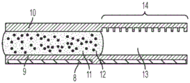
A digital microfluidic and analyte detection device comprising a first substrate and a second substrate, wherein the second substrate is separated from the first substrate by a gap, the first substrate comprising a plurality of electrodes to generate an electrical actuation force on a liquid droplet; and an array of wells sized to hold a portion of the liquid droplet, wherein at least a portion of the array of wells is positioned between one or more of the plurality of electrodes and the gap.
In some embodiments, the plurality of electrodes are positioned on a surface of the first substrate. In certain embodiments, the device further comprises a first layer disposed on a surface of the first substrate and covering the plurality of electrodes. In some embodiments, the first substrate comprises a first portion at which the liquid droplet is introduced and a second portion to which the liquid droplet moves. In certain embodiments, the plurality of electrodes and the first layer extend from the first portion to a second portion of the first substrate. In certain embodiments, the array of wells is positioned in the second portion of the first substrate. In certain embodiments, the second substrate comprises a first portion and a second portion, wherein the first portion is in a facing arrangement with the first portion of the first substrate and the second portion is in a facing arrangement with the array of wells. In certain embodiments, the second portion of the second substrate is substantially transparent to facilitate optical interrogation of the array of wells.
In some embodiments, the device further comprises a second layer disposed on a surface of the first layer. In certain embodiments, the second layer extends over the first and second portions of the first substrate. In certain implementations, the first layer is a dielectric layer and the second layer is a hydrophobic layer. In certain embodiments, the array of wells is positioned in the second layer. In certain embodiments, the array of wells is positioned in the first layer. In certain embodiments, the array of wells has a hydrophilic surface.
In some embodiments, the well array comprises sidewalls oriented to facilitate the reception and retention of beads or particles present in a droplet moving over the well array. In certain embodiments, the array of wells comprises a first sidewall opposite a second sidewall, wherein the first sidewall is oriented at an obtuse angle with respect to the bottom of the well, and wherein the second sidewall is oriented at an acute angle with respect to the bottom of the well, wherein the movement of droplets is in a direction parallel to and from the first sidewall to the second sidewall. In certain embodiments, the array of wells has a frustoconical shape, and a narrower portion of the frustoconical shape provides an opening of the array of wells. In certain embodiments, the array of wells comprises a first sidewall opposite a second sidewall, wherein a top portion of the first sidewall is oriented at an obtuse angle with respect to the bottom of the well and a bottom portion of the sidewall is oriented perpendicular to the bottom of the well, and wherein the second sidewall is oriented perpendicularly with respect to the bottom of the well, wherein the movement of the droplet is in a direction parallel to the bottom of the well and from the first sidewall to the second sidewall, wherein the top portion of the first sidewall is at the opening of the well.
Also disclosed is a digital microfluidic and analyte detection device comprising a first substrate and a second substrate defining the device, wherein the second substrate is separated from the first substrate by a gap, wherein the device comprises a first portion and a second portion; and the first portion comprises a plurality of electrodes to drive a combination of a first liquid droplet containing an analyte of interest from a biological sample and a second liquid droplet containing at least one bead; and the second portion comprises an array of wells sized to hold a portion of the liquid droplet.
In some embodiments, the plurality of electrodes are positioned only in the first portion of the device. In certain embodiments, the plurality of electrodes are positioned on a surface of the first substrate. In some embodiments, the device further comprises a first layer disposed on a surface of the first substrate and covering the plurality of electrodes. In certain embodiments, the first substrate comprises a first portion at which the liquid droplet is introduced and a second portion to which the liquid droplet moves. In certain embodiments, the plurality of electrodes and the first layer extend from the first portion to a second portion of the first substrate. In certain embodiments, the array of wells is positioned in the second portion of the first substrate.
In certain embodiments, the second substrate comprises a first portion and a second portion, wherein the first portion is in a facing arrangement with the first portion of the first substrate and the second portion is in a facing arrangement with the array of wells.
In certain embodiments, the second portion of the second substrate is substantially transparent to facilitate optical interrogation of the array of wells. In certain embodiments, the plurality of electrodes are configured to move a droplet disposed in the gap toward a second portion of the device, the device comprising a capillary portion fluidly connecting the first portion with the second portion, wherein the capillary comprises a hydrophilic material to facilitate movement of the droplet from the first portion to the second portion via the capillary portion in the absence of an electrical force.
In some embodiments, the device further comprises a second layer disposed on the upper surface of the first layer. In certain embodiments, the second layer extends over the first substrate. In certain implementations, the first layer is a dielectric layer and the second layer is a hydrophobic layer.
In some embodiments, the plurality of apertures is positioned in the second layer. In certain embodiments, the array of wells is positioned in the first layer. In certain embodiments, the array of wells has a hydrophilic surface. In certain embodiments, the well comprises a sidewall oriented to facilitate the reception and retention of nano-beads or nano-particles present in a droplet moving over the well array. In certain embodiments, the well comprises a first sidewall opposite a second sidewall, wherein the first sidewall is oriented at an obtuse angle with respect to the bottom of the well, and wherein the second sidewall is oriented at an acute angle with respect to the bottom of the well, wherein the movement of the droplet is in a direction parallel to and from the first sidewall to the second sidewall. In certain embodiments, the well has a frustoconical shape, and a narrower portion of the frustoconical shape provides an opening of the well. In certain embodiments, the well comprises a first sidewall opposite a second sidewall, wherein a top portion of the first sidewall is oriented at an obtuse angle with respect to the bottom of the well and a bottom portion of the sidewall is oriented perpendicular to the bottom of the well, and wherein the second sidewall is oriented perpendicular to the bottom of the well, wherein the movement of the droplet is in a direction parallel to the bottom of the well and from the first sidewall to the second sidewall, wherein the top portion of the first sidewall is at the opening of the well.
Also disclosed herein is a surface acoustic wave microfluidic and analyte detection device comprising a first substrate and a second substrate, wherein the second substrate is separated from the first substrate by a gap, wherein the device comprises a first portion comprising a superstrate coupled to a surface acoustic wave generating component and a second portion comprising a superstrate coupled to a second substrate; and the second portion comprises a plurality of apertures positioned on the first substrate or the second substrate.
In some embodiments, the cover sheet includes a phononic structure on an upper surface of the cover sheet. In certain embodiments, the superstrate covers the piezoelectric crystal layer. In certain embodiments, the second substrate is substantially transparent.
Also disclosed herein is a surface acoustic wave microfluidic and analyte detection device comprising a first substrate and a second substrate, wherein the second substrate is separated from the first substrate by a gap, the first substrate comprises a plurality of pores, and the second substrate comprises a phononic structure, wherein the plurality of pores and the phononic structure are positioned opposite each other.
In some embodiments, the second substrate is a superstrate. In certain embodiments, the superstrate is disposed on the second substrate and the phononic structure is located on the superstrate. In certain embodiments, the first substrate, second substrate, and superstrate are substantially transparent.
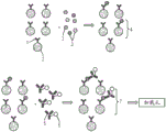
Methods of detecting or measuring an analyte of interest in a liquid droplet are also disclosed. In certain embodiments, the method comprises the steps of: providing a first liquid droplet comprising an analyte of interest, providing a second liquid droplet comprising at least one solid support comprising a specific binding member that binds to the analyte of interest, applying a force using energy to manipulate the first liquid droplet and the second liquid droplet to create a mixture, moving all or at least a portion of the mixture to an array of wells, wherein one or more wells of the array are of a size sufficient to accommodate the at least one solid support, adding a detectable label to the mixture before or after moving a portion of the mixture to the array of wells, and detecting the analyte of interest in the wells.
In certain embodiments, the at least one solid support comprises at least one binding member that specifically binds the analyte of interest. In certain embodiments, the method comprises: adding a detectable label to the mixture prior to moving at least a portion of the mixture to the array of wells. In certain embodiments, the method comprises: after moving at least a portion of the mixture to the array of wells, a detectable label is added to the mixture. In certain embodiments, the detectable label comprises at least one binding member that specifically binds the analyte of interest. In certain embodiments, the detectable label comprises a chromophore, a fluorescent compound, an enzyme, a chemiluminescent compound, or a radioactive compound. In certain embodiments, the binding member is a receptor or an antibody.
In certain embodiments, the energy used is electrical or acoustic. In certain embodiments, the electrical actuation force is droplet actuation, electrophoresis, electrowetting, dielectrophoresis, electrostatic actuation, electric field mediation, electrode mediation, capillary force, chromatography, centrifugation, or aspiration. In certain embodiments, the acoustic force is a surface acoustic wave.
In certain embodiments, generating an electrical actuation force comprises generating an alternating current. In certain embodiments, the alternating current has a root mean square (rms) voltage of 10V or more. In certain other embodiments, the alternating current has a frequency in the radio frequency range.
In certain embodiments, the first liquid droplet is a polarizable liquid, the second liquid droplet is a polarizable liquid, the mixture is a polarizable liquid, or both the first and second liquid droplets are each polarizable liquids.
In certain embodiments, the method further comprises positioning at least a portion of the mixture over the array of wells using an electric actuation force. In certain other embodiments, the method further comprises positioning at least a portion of the mixture over the array of wells using a capillary element configured to facilitate movement of the mixture to the array of wells.
In certain embodiments, the support is a magnetic solid support. In certain other embodiments, when a magnetic solid support is used, the electric driving force and the magnetic field are applied from opposite directions relative to at least a portion of the mixture. In certain embodiments, the method further comprises mixing the mixture as follows: moving the mixture back and forth, moving the mixture in a circular pattern, dividing the mixture into two or more sub-mixtures and combining the sub-mixtures. In certain embodiments, the mixture is an aqueous liquid. In certain other embodiments, the mixture is an immiscible liquid. In certain other embodiments, the liquid droplet is a hydrophobic liquid droplet. In certain embodiments, the array of wells has a hydrophilic surface. In certain other embodiments, the array of wells has a hydrophobic surface. In certain embodiments, the substrate comprises a hydrophilic surface. In certain other embodiments, the substrate comprises a hydrophobic surface. In certain embodiments, the method further comprises generating an electrical actuation force with a series of electrodes to move the mixture to the array of wells, thereby sealing the loaded wells.
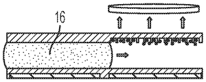
In certain embodiments, one or more wells of the array are loaded with at least one solid support. In certain other embodiments, the loading comprises applying a magnetic field to facilitate movement of at least one solid support into one or more wells of the array. In certain other embodiments, the method further comprises removing any solid support that was not loaded into the wells of the array after the loading. In certain other embodiments, the removing comprises generating an electrical actuation force with the series of electrodes to move the polarizable fluid droplets to the array of wells to move at least a portion of the mixture a distance away from the array of wells. In certain other embodiments, the removing comprises generating an electrical actuation force with the series of electrodes to move an aqueous wash droplet across the array of wells.
In certain embodiments, the methods are performed using a microfluidic device, a digital microfluidic Device (DMF), a surface acoustic wave-based microfluidic device (SAW), an integrated DMF and analyte detection device, an integrated SAW and analyte detection device, or a robotics-based assay processing unit.
In other embodiments, the method comprises the steps of: providing a first liquid droplet containing an analyte of interest, providing a second liquid droplet containing a detectable label containing a specific binding member that binds to the analyte of interest, applying a force using energy to manipulate the first liquid droplet and the second liquid droplet to create a mixture, moving all or at least a portion of the mixture to an array of wells, and detecting the analyte of interest in the wells.
In certain embodiments, the detectable label comprises a chromophore, a fluorescent compound, an enzyme, a chemiluminescent compound, or a radioactive compound. In certain embodiments, the binding member is a receptor or an antibody.
In certain embodiments, the energy used is electrical or acoustic. In certain embodiments, the electrical actuation force is droplet actuation, electrophoresis, electrowetting, dielectrophoresis, electrostatic actuation, electric field mediation, electrode mediation, capillary force, chromatography, centrifugation, or aspiration. In certain embodiments, the acoustic force is a surface acoustic wave.
In certain embodiments, generating an electrical actuation force comprises generating an alternating current. In certain embodiments, the alternating current has a root mean square (rms) voltage of 10V or more. In certain other embodiments, the alternating current has a frequency in the radio frequency range.
In certain embodiments, the first liquid droplet is a polarizable liquid, the second liquid droplet is a polarizable liquid, the mixture is a polarizable liquid, or both the first and second liquid droplets are each polarizable liquids.
In certain embodiments, the method further comprises positioning at least a portion of the mixture over the array of wells using an electric actuation force. In certain other embodiments, the method further comprises positioning at least a portion of the mixture over the array of wells using a capillary element configured to facilitate movement of the mixture to the array of wells.
In certain embodiments, the method further comprises mixing the mixture as follows: moving the mixture back and forth, moving the mixture in a circular pattern, dividing the mixture into two or more sub-mixtures and combining the sub-mixtures. In certain embodiments, the mixture is an aqueous liquid. In certain other embodiments, the mixture is an immiscible liquid. In certain other embodiments, the liquid droplet is a hydrophobic liquid droplet. In certain embodiments, the array of wells has a hydrophilic surface. In certain other embodiments, the array of wells has a hydrophobic surface. In certain embodiments, the substrate comprises a hydrophilic surface. In certain other embodiments, the substrate comprises a hydrophobic surface. In certain embodiments, the method further comprises generating an electrical actuation force with a series of electrodes to move the mixture to the array of wells, thereby sealing the loaded wells.
In certain embodiments, one or more wells of the array are loaded with at least one detectable label. In certain other embodiments, the removing comprises generating an electrical actuation force with the series of electrodes to move the polarizable fluid droplets to the array of wells to move at least a portion of the mixture a distance away from the array of wells. In certain other embodiments, the removing comprises generating an electrical actuation force with the series of electrodes to move an aqueous wash droplet across the array of wells.
In certain embodiments, the methods are performed using a microfluidic device, a digital microfluidic Device (DMF), a surface acoustic wave-based microfluidic device (SAW), an integrated DMF and analyte detection device, an integrated SAW and analyte detection device, or a robotics-based assay processing unit.
In other embodiments, the method comprises the step of measuring an analyte of interest in a liquid droplet, the method comprising: providing a first liquid droplet comprising an analyte of interest, providing a second liquid droplet comprising at least one solid support comprising a specific binding member that binds to the analyte of interest, applying a force using energy to manipulate the first liquid droplet and the second liquid, thereby creating a mixture, moving all or at least a portion of the mixture to an array of wells, wherein one or more wells of the array are of a size sufficient to accommodate the at least one solid support, adding a detectable label to the mixture before or after moving a portion of the mixture to the array of wells, and measuring the detectable label in the wells.
In certain embodiments, the at least one solid support comprises at least one binding member that specifically binds the analyte of interest. In certain embodiments, the method comprises: adding a detectable label to the mixture prior to moving at least a portion of the mixture to the array of wells. In certain embodiments, the method comprises: after moving at least a portion of the mixture to the array of wells, a detectable label is added to the mixture. In certain embodiments, the detectable label comprises at least one binding member that specifically binds the analyte of interest. In certain embodiments, the detectable label comprises a chromophore, a fluorescent compound, an enzyme, a chemiluminescent compound, or a radioactive compound. In certain embodiments, the binding member is a receptor or an antibody.
In certain embodiments, the energy used is electrical or acoustic. In certain embodiments, the electrical actuation force is droplet actuation, electrophoresis, electrowetting, dielectrophoresis, electrostatic actuation, electric field mediation, electrode mediation, capillary force, chromatography, centrifugation, or aspiration. In certain embodiments, the acoustic force is a surface acoustic wave.
In certain embodiments, generating an electrical actuation force comprises generating an alternating current. In certain embodiments, the alternating current has a root mean square (rms) voltage of 10V or more. In certain other embodiments, the alternating current has a frequency in the radio frequency range.
In certain embodiments, the first liquid droplet is a polarizable liquid, the second liquid droplet is a polarizable liquid, the mixture is a polarizable liquid, or both the first and second liquid droplets are each polarizable liquids.
In certain embodiments, the method further comprises positioning at least a portion of the mixture over the array of wells using an electric actuation force. In certain other embodiments, the method further comprises positioning at least a portion of the mixture over the array of wells using a capillary element configured to facilitate movement of the mixture to the array of wells.
In certain embodiments, the support is a magnetic solid support. In certain other embodiments, when a magnetic solid support is used, the electric driving force and the magnetic field are applied from opposite directions relative to at least a portion of the mixture.
In certain embodiments, the method further comprises mixing the mixture as follows: moving the mixture back and forth, moving the mixture in a circular pattern, dividing the mixture into two or more sub-mixtures and combining the sub-mixtures.
In certain embodiments, the mixture is an aqueous liquid. In certain other embodiments, the mixture is an immiscible liquid. In certain other embodiments, the liquid droplet is a hydrophobic liquid droplet. In certain embodiments, the array of wells has a hydrophilic surface. In certain other embodiments, the array of wells has a hydrophobic surface. In certain embodiments, the substrate comprises a hydrophilic surface. In certain other embodiments, the substrate comprises a hydrophobic surface. In certain embodiments, the method further comprises generating an electrical actuation force with a series of electrodes to move the mixture to the array of wells, thereby sealing the loaded wells.
In certain embodiments, one or more wells of the array are loaded with at least one solid support. In certain other embodiments, the loading comprises applying a magnetic field to facilitate movement of at least one solid support into one or more wells of the array. In certain other embodiments, the method further comprises removing any solid support that was not loaded into the wells of the array after the loading. In certain other embodiments, the removing comprises generating an electrical actuation force with the series of electrodes to move the polarizable fluid droplets to the array of wells to move at least a portion of the mixture a distance away from the array of wells. In certain other embodiments, the removing comprises generating an electrical actuation force with the series of electrodes to move an aqueous wash droplet across the array of wells.
In certain embodiments, the methods are performed using a microfluidic device, a digital microfluidic Device (DMF), a surface acoustic wave-based microfluidic device (SAW), an integrated DMF and analyte detection device, an integrated SAW and analyte detection device, or a robotics-based assay processing unit.
In certain embodiments, the measuring comprises determining the total number of solid supports in a well of the array. In certain embodiments, the measuring comprises determining the number of solid supports in a well of an array comprising the detectable label. In certain embodiments, the measuring comprises: the number of solid supports containing a detectable label is subtracted from the total number of solid supports in the array well to determine the number of solid supports in the array well that do not contain any detectable label. In certain embodiments, the measuring comprises: determining the ratio of the number of solid supports containing detectable label to solid supports not containing any detectable label.
Also disclosed herein is a method of loading a well with particles, comprising generating an electric field with a plurality of electrodes to move a liquid droplet containing particles to an array of wells, wherein one or more wells of the array of wells are of a size sufficient to load particles therein; loading one or more wells with particles; and generating an electric field with the plurality of electrodes to move a polarizable fluid droplet to the array of wells to seal the array of wells.
In some embodiments, the method further comprises positioning the liquid droplet over the array of wells using an electric field. In some embodiments, the method further comprises positioning the liquid droplet over the array of wells using a capillary element configured to facilitate movement of the liquid droplet to the array of wells. In some embodiments, the particle is a magnetic bead. In some embodiments, the loading comprises applying a magnetic field to facilitate movement of one or more magnetic beads into one or more wells of the array. In some embodiments, the array of wells has a hydrophilic surface. In some embodiments, the array of wells has a hydrophobic surface. In some embodiments, the generating an electric field comprises generating an alternating current. In certain embodiments, the alternating current has a root mean square (rms) voltage of 10V or more. In certain embodiments, the alternating current has a frequency in the radio frequency range.
Also disclosed herein is a method of forming a digital microfluidic and analyte detection device, comprising unrolling a first roll comprising a first substrate to position a first portion of the first substrate at a first location; forming a plurality of electrodes on a first portion of the first substrate at the first location; and forming an array of apertures on a second portion of the first substrate at a second location.
In some embodiments, the method further comprises: before forming the array of apertures, unwinding the first roll to position the second portion adjacent to the first portion of the first substrate at the second location. In some embodiments, the method further comprises: unwinding a second roll comprising a second substrate to position a third portion of a third substrate at a third location; and bonding the second substrate and the first substrate at the third location in a manner sufficient to position the second substrate in spaced relation to the first substrate.
Also disclosed herein is a method of forming an integrated digital microfluidic and analyte detection device, comprising unrolling a first roll comprising a first substrate to position a first portion of the first substrate at a first location; forming a plurality of electrodes on a first portion of the first substrate at the first location; unwinding a second roll comprising a second substrate to position a second portion of the second substrate at a second location; forming an array of apertures in the second portion at a second location; and bonding the second substrate to the first substrate in a manner sufficient to: positioning the second substrate spaced apart from the first substrate; and positioning the second portion over the first portion, or over a third portion adjoining the first portion of the first substrate, wherein the array of apertures faces the first substrate.
In some embodiments, forming the array of apertures comprises using thermal or ultraviolet nanoimprint lithography, a nanoimprint roller (roller), laser ablation, or by adhering a preformed substrate comprising the array of apertures to the first portion of the first substrate. In some embodiments, the method further comprises subjecting the first substrate to intense heat, pressure, or ultraviolet light to form phononic structures on or within the first substrate using a mold.
In some embodiments, the method further comprises applying a hydrophobic material and/or a dielectric material on the series of electrodes using a printer device. In some embodiments, the hydrophobic material and/or the dielectric material comprises a cured material. In some embodiments, the method further comprises applying heat or ultraviolet light to cure the applied hydrophobic material and/or dielectric material. In some embodiments, the method further comprises dicing (dicing) the first and second substrates to produce an adhesive substrate comprising the first and second portions.
Also disclosed herein is a method of detecting a target analyte in a liquid droplet, the method comprising: providing a first liquid droplet comprising a target analyte; providing a second liquid droplet comprising a specific binding member and a labeled analyte, wherein the binding member is immobilized on at least one solid support, the specific binding member specifically binds to the analyte of interest, and the labeled analyte is the analyte of interest labeled with a detectable label; applying a force using energy to manipulate the first liquid droplet and the second liquid droplet, thereby creating a mixture; and moving all or at least a portion of the mixture to an array of wells, wherein one or more wells of the array are of a size sufficient to accommodate the at least one solid support.
Also disclosed herein is a method of detecting a target analyte in a liquid droplet, comprising providing a first liquid droplet comprising a target analyte; providing a second liquid droplet comprising an immobilized analyte and at least one specific binding member, wherein the immobilized analyte is an analyte of interest immobilized on at least one solid support, the at least one specific binding member specifically binds to the analyte of interest, and the at least one specific binding member is labeled with a detectable label; applying a force using energy to manipulate the first liquid droplet and the second liquid droplet, thereby creating a mixture; moving all or at least a portion of the mixture to an array of wells, wherein one or more wells of the array are of a size sufficient to accommodate the at least one solid support; and detecting the target analyte in the well.
Drawings
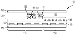
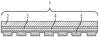
Fig. 1A illustrates a side view of an integrated digital microfluidic and analyte detection device, according to one embodiment.
Fig. 1B illustrates a side view of an integrated digital microfluidic and analyte detection device, according to another embodiment.
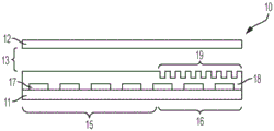
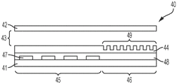
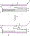
Fig. 2A illustrates a side view of an integrated digital microfluidic and analyte detection device, according to one embodiment.
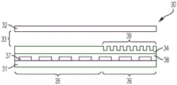
Fig. 2B illustrates a side view of an integrated digital microfluidic and analyte detection device, according to another embodiment.
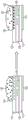
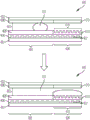
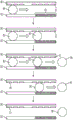
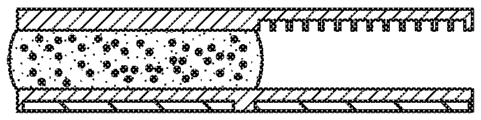
Fig. 3A illustrates a side view of the device of fig. 2A, wherein a liquid droplet is moving in the device.
Fig. 3B illustrates a side view of the device of fig. 2B, wherein a droplet is moving in the device.
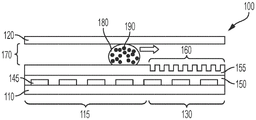
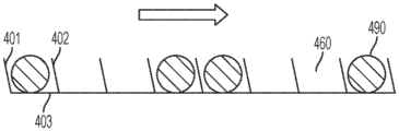
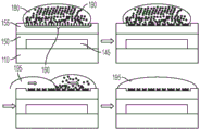
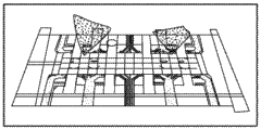
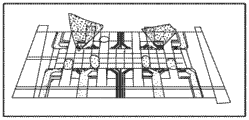
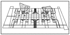
FIG. 4A illustrates a side view of the device of FIG. 2A in which a particle/bead containing droplet is moving onto an array of wells.
FIG. 4B illustrates a side view of the device of FIG. 2B in which a particle/bead-containing droplet and an immiscible fluid droplet are moving onto an array of wells.
Figure 5 illustrates the movement of an aqueous droplet over the array of wells using the hydrophilic capillary region of the device.
Figure 6 illustrates an aqueous droplet being moved over an array of wells.
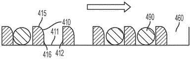
Fig. 7A-7B illustrate various example orientations of the sidewalls of the holes.
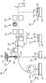
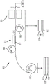
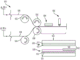
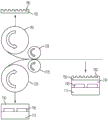
Fig. 8 illustrates one embodiment of fabricating a second (e.g., bottom) substrate of a digital microfluidic and analyte detection device.
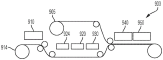
Fig. 9 illustrates one embodiment of fabricating a first (e.g., top) substrate of a digital microfluidic and analyte detection device.
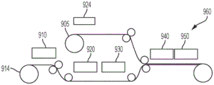
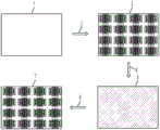
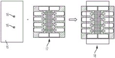
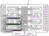
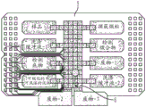
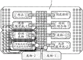
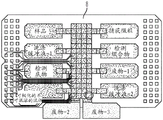
FIG. 10 illustrates one embodiment of assembling a top substrate and a bottom substrate to fabricate a plurality of digital microfluidic and analyte detection devices.
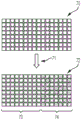
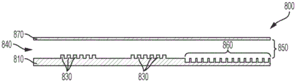
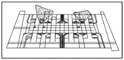
Fig. 11A and 11B show views from the top of a bottom substrate of an exemplary digital microfluidic and analyte detection device of the present disclosure.
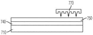
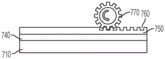
Fig. 12A-12D illustrate an embodiment of fabricating an array of wells into an integrated digital microfluidic and analyte detection device.
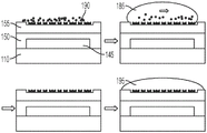
Figure 13A illustrates a side view of one embodiment of a surface acoustic feature of an integrated microfluidic and analyte device and aperture array.
Fig. 13B illustrates a side view of another embodiment of a surface acoustic feature of an integrated microfluidic and analyte device and an array of wells.
FIGS. 14A-14B illustrate one embodiment of fabricating a sample preparation component and an aperture array component.
Fig. 15 depicts an exemplary method of the present disclosure.
FIG. 16 illustrates an exemplary method for removing beads that are not located in the wells of the depicted apparatus.
FIG. 17 illustrates another exemplary method for removing beads that are not located in the wells of the depicted apparatus.
Fig. 18 depicts a schematic of the manufacturing process of a low-cost DMF chip.
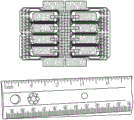
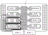
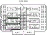
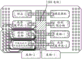
FIG. 19 depicts a single flex chip manufactured according to the schematic in FIG. 18.
Fig. 20 depicts actuation of droplets in DMF chips, according to embodiments of the present disclosure.
Figures 21A-21E depict performance of an immunoassay in a DMF chip, according to embodiments of the present disclosure.
Fig. 22A and 22B are schematic diagrams illustrating a method of design and fabrication of a DMF top electrode chip and well array, according to embodiments of the present disclosure.
Fig. 23 shows a schematic diagram of a hole design, according to an embodiment of the present disclosure.
Fig. 24A and 24B are schematic diagrams illustrating a well spacing pattern according to embodiments of the present disclosure.
Fig. 25 is a collection of magnified optical images of an array of apertures, according to an embodiment of the present disclosure.
Fig. 26 is a schematic diagram showing the assembly of an integrated DMF-well device from a DMF top electrode chip and well array, according to an embodiment of the present disclosure.
Fig. 27A-27G are a set of schematic diagrams showing immunoassays performed on an integrated DMF-well device, according to embodiments of the present disclosure.
Figure 28 is a schematic of an enzyme-linked immunosorbent assay (ELISA) -based sandwich immunoassay coupled to digital fluorescence detection in a well array, according to embodiments of the present disclosure.
Fig. 29 is a schematic diagram showing components for DMF-directed microparticle top-loading into a well array, according to an embodiment of the present disclosure.
Figures 30A-30D are a set of schematic diagrams illustrating steps of a Thyroid Stimulating Hormone (TSH) immunoassay using an integrated DMF-well device, according to embodiments of the present disclosure.
Detailed Description
The present invention discloses an integrated microfluidic and analyte detection device. Exemplary methods of using the integrated microfluidic and analyte detection devices and related systems are also provided herein.
Before the present invention is described in more detail, it is to be understood that this invention is not limited to particular embodiments described, as such may, of course, vary. It is also to be understood that the terminology used herein is for the purpose of describing particular embodiments only, and is not intended to be limiting, since the scope of the present invention will be limited only by the appended claims.
It must be noted that, as used herein and in the appended claims, the singular forms "a," "an," and "the" include plural referents unless the context clearly dictates otherwise. Thus, for example, reference to "an electrode" includes a plurality of such electrodes, and reference to "the aperture" includes reference to one or more apertures and equivalents thereof known to those skilled in the art, and so forth.
All publications mentioned herein are incorporated herein by reference to disclose and describe the methods and/or materials in connection with which the publications are cited. In the event of a conflict between the present disclosure and a publication incorporated by reference, the present disclosure controls.
Detailed Description
Embodiments of the present disclosure relate to methods, systems, and devices for analyzing analytes in a sample. In certain embodiments, the sample may be a biological sample.
1. Definition of
Before the embodiments of the present disclosure are described, it is to be understood that this invention is not limited to particular embodiments, as such may, of course, vary. It is also to be understood that the terminology used herein is for the purpose of describing particular embodiments only, and is not intended to be limiting.
As used herein, "comprising," "including," "having," "can," "containing," and variations thereof, are intended to be open-ended transition phrases, terms, or words that do not exclude the possibility of additional acts or structures. The singular forms "a", "an" and "the" include plural referents unless the context clearly dictates otherwise. The present disclosure also contemplates other embodiments that "comprise," consist of, "and" consist essentially of the embodiments or elements presented herein, whether or not explicitly stated.
In terms of the numerical ranges set forth herein, each intervening number between the two is expressly contemplated with the same degree of precision. For example, in the case of the range of 6-9, the numbers 7 and 8 are foreseen in addition to 6 and 9, and in the case of the range of 6.0-7.0, the numbers 6.0, 6.1, 6.2, 6.3, 6.4, 6.5, 6.6, 6.7, 6.8, 6.9 and 7.0 are explicitly foreseen.
"affinity" and "binding affinity" are used interchangeably herein to refer to the tendency or strength of binding of a binding member to an analyte. For example, binding affinity can be determined by an equilibrium dissociation constant (K)D) Dissociation rate (k)d) Or the binding rate (k)a) And (4) showing.
"analog" as used herein means a molecule having a structure similar to a target molecule (e.g., nucleoside analogs, nucleotide analogs, sugar phosphate analogs, analyte analogs, etc.). Analyte analogs are molecules that are similar in structure to the analyte, but for which the binding members have different affinities.
The term "aptamer" as used herein refers to an oligonucleotide or peptide molecule that can bind a preselected target (including small molecules, proteins, peptides, etc.) with high affinity and specificity. Aptamers can take a variety of shapes due to their tendency to form helices and single-stranded loops. The oligonucleotide or nucleic acid aptamer may be a single stranded DNA or RNA (ssDNA or ssRNA) molecule. Peptide aptamers may include short variable peptide domains that are linked to a protein scaffold at both termini.
"beads" and "particles" are used interchangeably herein and refer to a substantially spherical solid support.
"component," "components," "multiple components," or "at least one component" generally refers to a capture antibody, detection reagent or conjugate, calibrator, control, sensitivity target set, container, buffer, diluent, salt, enzyme, cofactor for the enzyme, detection reagent, pretreatment reagent/solution, substrate (e.g., as a solution), stop solution, and the like, which may be included in a kit for assaying a test sample, such as a patient's urine, serum, whole blood, tissue aspirate, or plasma sample, according to the methods described herein and other methods known in the art. Some components may be in solution or lyophilized for reconstitution for assay.
"Digital Microfluidics (DMF)", "digital microfluidic module (DMF module)" or "digital microfluidic device (DMF device)" used interchangeably herein refers to a module or device that utilizes digital or droplet-based microfluidic technology to provide manipulation of liquids in the form of dispersed and small-volume droplets. Digital microfluidics uses the principles of emulsion science to establish fluid-fluid dispersion (primarily water-in-oil emulsions) in a channel. It allows the production of monodisperse droplets/bubbles or has a very low polydispersity. Digital microfluidics is based on the microscopic manipulation of discrete fluidic droplets within a reconfigurable network. Complex instructions can be programmed by combining the basic operations of droplet formation, translocation, splitting and merging.
Digital microfluidics operates on discrete volumes of fluid, which can be manipulated by binary electrical signals. By using discrete unit volumes of droplets, a microfluidic run can be defined as a set of repeated basic operations, i.e., moving one unit of fluid over one unit of distance. The surface tension properties of the liquid can be used to form droplets. The driving of the droplet is based on the presence of electrostatic forces generated by electrodes placed below the bottom surface where the droplet is located. Different types of electrostatic forces may be used to control the shape and motion of the droplet. One technique that can be used to establish the aforementioned electrostatic forces is based on dielectrophoresis, which relies on permittivity differences between the droplet and the surrounding medium, and can utilize high frequency AC electric fields. Another technique that can be used to establish the aforementioned electrostatic forces is based on electrowetting, which relies on the dependence of the surface tension between a liquid droplet present on a surface and the surface on the electric field applied to the surface.
The "drag tag" represents a mobility modifier. The pull-tag can be a genetically engineered highly repetitive polypeptide ("protein polymer") designed to be large, water soluble and fully monodisperse. Positively charged arginines may be intentionally introduced into the amino acid sequence at regular intervals to increase hydrodynamic resistance without increasing the length of the drag tag. Pull tags are described in U.S. patent publication No. 20120141997, which is incorporated herein by reference.
As used herein, "enzyme-cleavable sequence" refers to any nucleic acid sequence that can be cleaved by an enzyme. For example, the enzyme may be a protease or an endonuclease, such as a restriction endonuclease (also referred to as a restriction enzyme). Restriction endonucleases are capable of recognizing and cleaving DNA molecules at specific DNA cleavage sites between predetermined nucleotides. Some endonucleases (e.g., such as Fokl) comprise a cleavage domain that nonspecifically cleaves DNA at a particular position, regardless of the nucleotide present at that position. In some embodiments, the specific DNA cleavage site and the DNA recognition site of the restriction endonuclease are the same.
"globular protein" means a water-soluble protein having a roughly spherical shape. Examples of globular proteins include, but are not limited to, ovalbumin, beta-globulin, C-reactive protein, fibrin, hemoglobin, IgG, IgM, and thrombin.
"label" or "detectable label" are used interchangeably herein to refer to a moiety attached to a specific binding member or analyte such that a reaction between the specific binding member and the analyte is detectable, and a specific binding member or analyte so labeled is referred to as "detectably labeled". The label may produce a signal detectable by visual means or instrumental means. The various indicia include: (i) a tag attached to a specific binding member or analyte via a cleavable linker; or (ii) a signal-generating substance such as a chromophore, a fluorescent compound, an enzyme, a chemiluminescent compound, a radioactive compound, or the like. Representative examples of labels include moieties that generate light (e.g., acridinium compounds) and moieties that generate fluorescence (e.g., fluorescein). Other markers are described herein. In this regard, the moiety may not be detectable by itself, but may become detectable upon reaction with another moiety. Use of the term "detectably labeled" is intended to include such labeling.
"microparticle" and "microbead" are used interchangeably herein and refer to a microbead or microparticle that is allowed to occupy or settle in an array of wells (e.g., as in an array of wells in a detection module). The microparticles and microbeads may contain at least one specific binding member that binds the analyte of interest and at least one detectable label. Alternatively, the microparticles and microbeads may contain a first specific binding member that binds the analyte and a second specific binding member that also binds the analyte and contains at least one detectable label.
"nucleobase" or "base" refers to those naturally occurring and synthetic heterocyclic moieties commonly known in the art of nucleic acid or polynucleotide technology or peptide nucleic acid technology for the production of polymers. Non-limiting examples of suitable nucleobases include: adenine, cytosine, guanine, thymine, uracil, 5-propynyl-uracil, 2-thio-5-propynyl-uracil, 5-methylcytosine, pseudoisocytosine, 2-thiouracil and 2-thiothymine, 2-aminopurine, N9- (2-amino-6-chloropurine), N9- (2, 6-diaminopurine), hypoxanthine, N9- (7-deaza-guanine), N9- (7-deaza-8-aza-guanine) and N8- (7-deaza-8-aza-adenine). Nucleobases can be linked to other moieties to form nucleosides, nucleotides, and nucleoside/nucleotide analogs.
"nucleoside" means a compound consisting of a purine, deazapurine or pyrimidine nucleoside base (e.g., adenine, guanine, cytosine, uracil, thymine, 7-deazaadenine, 7-deazaguanosine) attached at the 1 'position to the anomeric carbon of a pentose such as ribose, 2' -deoxyribose or 2',3' -dideoxyribose.
As used herein, "nucleotide" means a phosphate ester of a nucleoside, e.g., a mono-, di-, or tri-phosphate ester, wherein the most common esterification site is the hydroxyl group attached to the C-5 position of the pentose.
"nucleobase polymer" or "nucleobase oligomer" refers to two or more nucleobases that are linked by bonds to form an oligomer. Nucleobase polymers or oligomers include, but are not limited to: polynucleotides and oligonucleotides (e.g., DNA and RNA polymers and oligomers), polynucleotide and oligonucleotide analogs, and polynucleotide and oligonucleotide mimetics, such as polyamide or peptide nucleic acids. The nucleobase polymers or oligomers may vary in size from a few nucleobases to hundreds of nucleobases or to thousands of nucleobases. The nucleobase polymer or oligomer may comprise about 2-100 nucleobases or about 8000-10000 nucleobases. For example, the nucleobase polymer or oligomer may have at least about 2 nucleobases, at least about 5 nucleobases, at least about 10 nucleobases, at least about 20 nucleobases, at least about 30 nucleobases, at least about 40 nucleobases, at least about 50 nucleobases, at least about 60 nucleobases, at least about 70 nucleobases, at least about 80 nucleobases, at least about 90 nucleobases, at least about 100 nucleobases, at least about 200 nucleobases, at least about 300 nucleobases, at least about 400 nucleobases, at least about 500 nucleobases, at least about 600 nucleobases, at least about 700 nucleobases, at least about 800 nucleobases, at least about 900 nucleobases, at least about 1000 nucleobases, at least about 2000 nucleobases, at least about 3000 nucleobases, at least about 4000 nucleobases, At least about 5000 nucleobases, at least about 6000 nucleobases, at least about 7000 nucleobases, at least about 8000 nucleobases, at least about 9000 nucleobases or at least about 10000 nucleobases.
By "polymeric brush" is meant a polymeric layer attached to a surface with one end. The polymers come close together and form a layer or coating (coating) that forms its own environment. The brush may be in a solvent state (when the hanger chain is immersed in the solvent) or in a molten state (when the hanger chain completely fills the available space). In addition, there is a separate class of polyelectrolyte brushes when the polymer chains themselves carry electrostatic charges. The brush can be characterized by a high density of graft chains. The limited space then leads to strong extension of the chain, and unusual performance of the system. The brush may be used to stabilize the gel, reduce friction between surfaces, and provide lubrication in the prosthetic joint.
"Polynucleotide" or "oligonucleotide" means a polymer or oligomer of nucleobases in which the nucleobases are linked by sugar phosphate linkages (sugar-phosphate backbone). Exemplary polynucleotides and oligonucleotides include polymers of 2' -Deoxyribonucleotides (DNA) and polymers of Ribonucleotides (RNA). The polynucleotide can consist entirely of ribonucleotides, entirely of 2' -deoxyribonucleotides, or a combination thereof. The term nucleic acid includes the terms polynucleotide and oligonucleotide, and includes single-stranded and double-stranded polymers of nucleotide monomers.
"Polynucleotide analog" or "oligonucleotide analog" refers to a polymer or oligomer of nucleobases in which the nucleobases are linked by a sugar phosphate backbone comprising one or more sugar phosphate analogs. Typical sugar phosphate analogs include, but are not limited to: sugar alkylphosphonates, sugar phosphoramidites, sugar alkylphosphotriesters or substituted alkylphosphotriesters, sugar phosphorothioates, sugar phosphorodithioates, sugar phosphates, and sugar phosphate analogs wherein the sugar is other than 2' -deoxyribose or ribose, the nucleobase polymer having a positively charged sugar-guanidino interconnection such as those described in U.S. Pat. No. 6,013,785 and U.S. Pat. No. 5,696,253.
As used herein, "receptor" refers to a protein-molecule that recognizes and responds to endogenous chemical signals. When such endogenous chemical signals bind to receptors, they cause some form of cell/tissue-response. Examples of receptors include, but are not limited to, neural receptors, hormone receptors, nutrient receptors, and cell surface receptors.
As used herein, "separator" means a chemical moiety: it extends from the specific binding member a cleavable group, or it provides a link between the binding member and the support, or it extends from the photo-cleavable moiety a label/tag. In some embodiments, one or more spacers may be included at the N-or C-terminus of the polypeptide or nucleotide-based tag or label in order to provide optimal distance of the sequence from the specific binding member. Spacers may include, but are not limited to: 6-aminocaproic acid, 6-aminocaproic acid; 1, 3-diaminopropane; 1, 3-diaminoethane; polyethylene glycol (PEG) polymer groups, and short amino acid sequences of 1-5 amino acids, such as a polyglycine sequence.
"specific binding partner" or "specific binding member" are used interchangeably herein to mean one of two different molecules that specifically recognizes the other molecule, relative to significantly less recognition of the other molecule. One of the two different molecules has a region on the surface or in the lumen that specifically binds to, and is thus defined complementary to, the specific spatial and polar composition of the other molecule. The molecule may be a member of a specific binding pair. For example, specific binding members may include, but are not limited to, proteins, such as receptors, enzymes, antibodies and aptamers, peptides, nucleotides, oligonucleotides, polynucleotides, and combinations thereof.
As used herein, both "tag" or "tag molecule" refer to a molecule (e.g., cleaved from a second binding member, dissociated from a target analyte): which is used to provide an indication of the level of analyte in the sample. These terms refer to a single tag molecule or a plurality of identical tag molecules. Also, unless otherwise specified, "tag" means a label or one or more labels.
As used herein, "tracer" refers to an analyte or analyte fragment conjugated to a tag or label, wherein the analyte conjugated to the tag or label can effectively compete with the analyte for sites on an antibody specific for the analyte. For example, the tracer may be an analyte or an analogue of an analyte, such as cyclosporin or its analogue ISA247, vitamin D and its analogues, sex hormones and their analogues, and the like.
Unless defined otherwise, all technical and scientific terms used herein have the same meaning as commonly understood by one of ordinary skill in the art. In case of conflict, the present document, including definitions, will control. Preferred methods and materials are described below, but methods and materials similar or equivalent to those described herein can also be used in the practice or testing of the present invention. All publications, patent applications, patents, and other references mentioned herein are incorporated by reference in their entirety to disclose and describe the methods and/or materials in connection with which the publications are cited. The materials, methods, and examples disclosed herein are illustrative only and not intended to be limiting.
Method for analyte analysis
Provided herein are methods for analyte analysis. The method may involve single molecule counting. In certain embodiments, a method for analyte analysis may involve assessing an analyte present in a sample. In certain embodiments, the assessment can be used to determine the presence and/or concentration of an analyte in a sample. In certain embodiments, the methods may also be used to determine the presence and/or concentration of a plurality of different analytes present in a sample.
Provided herein are methods for detecting a target analyte in a liquid droplet (wherein the target analyte is from an assay or a biological sample). The method comprises the following steps: providing a first liquid droplet comprising an analyte of interest, providing a second liquid droplet comprising at least one solid support, e.g., such as a magnetic solid support (such as beads), the solid support containing a specific binding member that binds the analyte of interest, applying a force using energy to manipulate the first liquid droplet (which contains the analyte of interest) and the second liquid (which contains at least one solid support) to create a mixture, moving all or at least a portion of the mixture to an array of wells (wherein one or more wells of the array are of a size sufficient to accommodate the at least one solid support), adding at least one detectable label to the mixture before, after, or both before and after moving a portion of the mixture to the array of wells, and detecting the target analyte in the wells. In certain embodiments, "applying a force to manipulate the first and second liquid droplets using energy" means providing or applying a force that operates (such as merges or combines) at least the first and second liquid droplets (and optionally additional droplets) into a mixture using non-mechanical forces (i.e., energy generated without the use of pumps and/or valves, for example). Examples of non-mechanical forces that may be used in the methods described herein include electrical driving forces (such as droplet driving, electrophoresis, electrowetting, dielectrophoresis, electrostatic driving, electric field mediated, electrode mediated, capillary forces, chromatography, centrifugation, or aspiration) and/or acoustic forces (such as surface acoustic waves (or "SAW")). In certain embodiments, the electrical actuation force generated is an alternating current. For example, the alternating current may have a root mean square (rms) voltage of 10V, 15V, 20V, 25V, 30V, 35V, or higher. For example, such an alternating current may have an rms voltage of 10V or higher, 15V or higher, 20V or higher, 25V or higher, 30V or higher, or 35V or higher. Alternatively, the alternating current may have a frequency in the radio frequency range.
In certain embodiments, if a magnetic solid support is used, an electric driving force and a magnetic field may be applied and applied from opposite directions relative to at least a portion of the mixture. In certain other embodiments, the mixture is mixed by moving it as follows: before and after, in a cyclic fashion or by dividing it into two or more sub-mixtures and then combining the sub-mixtures. In certain other embodiments, an electrical actuation force can be generated using a series or plurality of electrodes (i.e., at least 2 or more, at least 3 or more, at least 4 or more, at least 5 or more, at least 6 or more, at least 7 or more, at least 8 or more, at least 9 or more, at least 10 or more, at least 11 or more, at least 12 or more, at least 13 or more, at least 14 or more, at least 15 or more, etc.) to move the mixture to the array of wells, thereby sealing the wells (which are loaded with at least one solid support).
In certain embodiments, moving all or at least a portion of the mixture to the array of wells results in the loading (filling and/or placement) of at least one solid support into the array of wells. In certain embodiments, a magnetic field is used to facilitate movement of the mixture, and thus movement of at least one solid support into one or more wells of the array. In certain embodiments, after loading at least one solid support into a well, any solid support not loaded into the well can be removed using conventional techniques known in the art. For example, such removal may comprise generating an electrical actuation force (such as that described above) with a series or plurality of electrodes to move a fluid droplet (such as a polarizable fluid droplet) to the array of wells, thereby moving at least a portion of the mixture a distance (the length of which is not critical) away from the array of wells. In certain embodiments, an aqueous wash liquid may be used to remove solid supports that are not bound to any target analyte. In such embodiments, the removing comprises generating an electrical actuation force with a series or plurality of electrodes to move an aqueous wash solution (or wash) droplet (third droplet) through the array of wells. The amount and type of aqueous liquid used for the wash is not critical.
In certain embodiments, the mixture in the method is an aqueous liquid. In other embodiments, the mixture is an immiscible liquid. In other embodiments, the liquid droplet is a hydrophobic liquid droplet. In other embodiments, the liquid droplet is a hydrophilic liquid droplet. In certain embodiments, the array of wells used in the method has a hydrophobic surface. In other embodiments, the array of wells has a hydrophilic surface.
In certain embodiments, the first liquid droplet used in the method is a polarizable liquid. In certain embodiments, the second liquid droplet used in the method is a polarizable liquid. In certain embodiments, the first liquid droplet and the second liquid droplet used in the method are polarizable liquids. In certain embodiments, the mixture is a polarizable liquid. In certain embodiments, one or more of the first droplet, the second droplet, and the mixture is a polarizable liquid.
In certain embodiments, the at least one solid support comprises at least one binding member that specifically binds the analyte of interest. In certain embodiments, the detectable label is added to the mixture prior to moving at least a portion of the mixture to the array of wells. In certain other embodiments, the detectable label is added to the mixture after moving at least a portion of the target analyte. In certain embodiments, the detectable label comprises at least one binding member that specifically binds the analyte of interest. In certain embodiments, the detectable label comprises a chromophore, a fluorescent compound, an enzyme, a chemiluminescent compound, or a radioactive compound. In certain embodiments, the binding member is a receptor, an aptamer, or an antibody. In certain embodiments, the method further comprises positioning at least a portion of the mixture over the array of wells using a capillary element configured to facilitate movement of the mixture to the array of wells.
In certain embodiments, the methods described herein are performed using a microfluidic device. In certain embodiments, the methods described herein are performed using a digital microfluidic Device (DMF). In certain embodiments, the methods described herein are performed using surface acoustic wave based microfluidic devices (SAW). In certain embodiments, the methods described herein are performed using an integrated DMF and analyte detection device. In certain embodiments, the methods described herein are performed using an integrated surface acoustic wave-based microfluidic device and an analyte detection device. In certain embodiments, the methods described herein are performed using a robotics-based assay processing unit.
Provided herein are methods for detecting a target analyte in a liquid droplet (wherein the target analyte is from an assay or a biological sample). The method comprises the following steps: providing a first liquid droplet containing an analyte of interest, providing a second liquid droplet containing at least one detectable label containing a specific binding member that binds to the analyte of interest, applying force using energy to manipulate the first liquid droplet (which contains the analyte of interest) and the second liquid (which contains at least one solid support) to create a mixture (i.e., an analyte/detectable label-specific binding member complex), moving all or at least a portion of the mixture to an array of wells (wherein one or more wells of the array are of a size sufficient to accommodate the at least one solid support), and detecting an analyte of interest in the wells. In certain embodiments, "applying a force to manipulate the first and second liquid droplets using energy" means providing or applying a force that operates (such as merges or combines) at least the first and second liquid droplets (and optionally additional droplets) into a mixture using non-mechanical forces (i.e., energy generated without the use of pumps and/or valves, for example). Examples of non-mechanical forces that may be used in the methods described herein include electrical driving forces (such as droplet driving, electrophoresis, electrowetting, dielectrophoresis, electrostatic driving, electric field mediated, electrode mediated, capillary forces, chromatography, centrifugation, or aspiration) and/or acoustic forces (such as surface acoustic waves (or "SAW")). In certain embodiments, the electrical actuation force generated is an alternating current. For example, the alternating current may have a root mean square (rms) voltage of 10V, 15V, 20V, 25V, 30V, 35V, or higher. For example, such an alternating current may have an rms voltage of 10V or higher, 15V or higher, 20V or higher, 25V or higher, 30V or higher, or 35V or higher. Alternatively, the alternating current may have a frequency in the radio frequency range.
In certain embodiments, the mixture is mixed by moving it as follows: before and after, in a cyclic fashion, or it is divided into two or more sub-mixtures and the sub-mixtures are then combined. In certain other embodiments, an electrical actuation force can be generated using a series or plurality of electrodes (i.e., at least 2 or more, at least 3 or more, at least 4 or more, at least 5 or more, at least 6 or more, at least 7 or more, at least 8 or more, at least 9 or more, at least 10 or more, at least 11 or more, at least 12 or more, at least 13 or more, at least 14 or more, at least 15 or more, etc.) to move the mixture to the array of wells, thereby sealing the wells (which are loaded with at least one solid support).
In certain embodiments, moving all or at least a portion of the mixture to the well array results in loading (filling and/or placement) of analyte/detectable label-specific binding member complexes into the well array. In certain embodiments, a magnetic field is used to facilitate movement of the mixture, and thus movement of at least one analyte/detectable label-specific binding member complex into one or more wells of the array. For example, such removal may comprise generating an electrical actuation force (such as that described above) with a series or plurality of electrodes to move a fluid droplet (such as a polarizable fluid droplet) to the array of wells, thereby moving at least a portion of the mixture a distance (the length of which is not critical) away from the array of wells. In certain embodiments, an aqueous wash liquid may be used to remove any detectable label-specific binding members that do not bind any analyte. In such embodiments, the removing comprises generating an electrical actuation force with a series or plurality of electrodes to move an aqueous wash solution (or wash) droplet (third droplet) through the array of wells. The amount and type of aqueous liquid used for the wash is not critical.
In certain embodiments, the mixture in the method is an aqueous liquid. In other embodiments, the mixture is an immiscible liquid. In other embodiments, the liquid droplet is a hydrophobic liquid droplet. In other embodiments, the liquid droplet is a hydrophilic liquid droplet. In certain embodiments, the array of wells used in the method has a hydrophobic surface. In other embodiments, the array of wells has a hydrophilic surface.
In certain embodiments, the first liquid droplet used in the method is a polarizable liquid. In certain embodiments, the second liquid droplet used in the method is a polarizable liquid. In certain embodiments, the first liquid droplet and the second liquid droplet used in the method are polarizable liquids. In certain embodiments, the mixture is a polarizable liquid. In certain embodiments, one or more of the first droplet, the second droplet, and the mixture is a polarizable liquid.
In certain embodiments, the detectable label is bound to at least one solid support. In certain embodiments, the detectable label comprises a chromophore, a fluorescent compound, an enzyme, a chemiluminescent compound, or a radioactive compound. In certain embodiments, the binding member is a receptor, an aptamer, or an antibody. In certain embodiments, the method further comprises positioning at least a portion of the mixture over the array of wells using a capillary element configured to facilitate movement of the mixture to the array of wells.
In certain embodiments, the methods described herein are performed using a microfluidic device. In certain embodiments, the methods described herein are performed using a digital microfluidic Device (DMF). In certain embodiments, the methods described herein are performed using surface acoustic wave based microfluidic devices (SAW). In certain embodiments, the methods described herein are performed using an integrated DMF and analyte detection device. In certain embodiments, the methods described herein are performed using an integrated surface acoustic wave-based microfluidic device and an analyte detection device. In certain embodiments, the methods described herein are performed using a robotics-based assay processing unit.
Provided herein are methods for measuring a target analyte in a liquid droplet (wherein the target analyte is from a test or biological sample). The method comprises the following steps: providing a first liquid droplet containing an analyte of interest, providing a second liquid droplet containing at least one solid support (e.g., a magnetic solid support such as a bead), the solid support containing a specific binding member that binds the analyte of interest, applying a force using energy to manipulate the first liquid droplet (which contains the analyte of interest) and the second liquid (which contains at least one solid support) to create a mixture, moving all or at least a portion of the mixture to an array of wells (wherein one or more wells of the array are of a size sufficient to accommodate the at least one solid support), adding at least one detectable label to the mixture before, after, or both before and after moving a portion of the mixture to the array of wells, and measuring the target analyte in the wells. In certain embodiments, "applying a force to manipulate the first and second liquid droplets using energy" means providing or applying a force that operates (such as merges or combines) at least the first and second liquid droplets (and optionally additional droplets) into a mixture using non-mechanical forces (i.e., energy generated without the use of pumps and/or valves, for example). Examples of non-mechanical forces that may be used in the methods described herein include electrical driving forces (such as droplet driving, electrophoresis, electrowetting, dielectrophoresis, electrostatic driving, electric field mediated, electrode mediated, capillary forces, chromatography, centrifugation, or aspiration) and/or acoustic forces (such as surface acoustic waves (or "SAW")). In certain embodiments, the electrical actuation force generated is an alternating current. For example, the alternating current may have a root mean square (rms) voltage of 10V, 15V, 20V, 25V, 30V, 35V, or higher. For example, such an alternating current may have an rms voltage of 10V or higher, 15V or higher, 20V or higher, 25V or higher, 30V or higher, or 35V or higher. Alternatively, the alternating current may have a frequency in the radio frequency range.
In certain embodiments, if a magnetic solid support is used, an electric driving force and a magnetic field may be applied and applied from opposite directions relative to at least a portion of the mixture. In certain other embodiments, the mixture is mixed by moving it as follows: before and after, in a cyclic fashion, or it is divided into two or more sub-mixtures and the sub-mixtures are then combined. In certain other embodiments, electrical actuation forces can be generated using a series or plurality of electrodes (i.e., at least 2 or more, at least 3 or more, at least 4 or more, at least 5 or more, at least 6 or more, at least 7 or more, at least 8 or more, at least 9 or more, at least 10 or more, at least 11 or more, at least 12 or more, at least 13 or more, at least 14 or more, at least 15 or more, etc.) to move the mixture to the array of wells, thereby sealing the wells (which are loaded with at least one solid support).
In certain embodiments, moving all or at least a portion of the mixture to the array of wells results in the loading (filling and/or placement) of at least one solid support into the array of wells. In certain embodiments, a magnetic field is used to facilitate movement of the mixture, and thus movement of at least one solid support into one or more wells of the array. In certain embodiments, after loading at least one solid support into a well, any solid support not loaded into the well can be removed using conventional techniques known in the art. For example, such removal may comprise generating an electrical actuation force (such as that described above) with a series or plurality of electrodes to move a fluid droplet (such as a polarizable fluid droplet) to the array of wells, thereby moving at least a portion of the mixture to a distance from the array of wells (the length of which is not critical). In certain embodiments, an aqueous wash liquid may be used to remove solid supports that are not bound to any target analyte. In such embodiments, the removing comprises generating an electrical actuation force with a series or plurality of electrodes to move an aqueous wash solution (or wash) droplet (third droplet) through the array of wells. The amount and type of aqueous liquid used for the wash is not critical.
In certain embodiments, the mixture in the method is an aqueous liquid. In other embodiments, the mixture is an immiscible liquid. In other embodiments, the liquid droplet is a hydrophobic liquid droplet. In other embodiments, the liquid droplet is a hydrophilic liquid droplet. In certain embodiments, the array of wells used in the method has a hydrophobic surface. In other embodiments, the array of wells has a hydrophilic surface.
In certain embodiments, the first liquid droplet used in the method is a polarizable liquid. In certain embodiments, the second liquid droplet used in the method is a polarizable liquid. In certain embodiments, the first liquid droplet and the second liquid droplet used in the method are polarizable liquids. In certain embodiments, the mixture is a polarizable liquid. In certain embodiments, one or more of the first droplet, the second droplet, and the mixture is a polarizable liquid.
In certain embodiments, the at least one solid support comprises at least one binding member that specifically binds the analyte of interest. In certain embodiments, the detectable label is added to the mixture prior to moving at least a portion of the mixture to the array of wells. In certain other embodiments, the detectable label is added to the mixture after moving at least a portion of the target analyte to the array of wells. In certain embodiments, the detectable label comprises at least one binding member that specifically binds the analyte of interest. In certain embodiments, the detectable label comprises a chromophore, a fluorescent compound, an enzyme, a chemiluminescent compound, or a radioactive compound. In certain embodiments, the binding member is a receptor, an aptamer, or an antibody. In certain embodiments, the method further comprises positioning at least a portion of the mixture over the array of wells using a capillary element configured to facilitate movement of the mixture to the array of wells.
In certain embodiments, the methods described herein are performed using a microfluidic device. In certain embodiments, the methods described herein are performed using a digital microfluidic Device (DMF). In certain embodiments, the methods described herein are performed using surface acoustic wave based microfluidic devices (SAW). In certain embodiments, the methods described herein are performed using an integrated DMF and analyte detection device. In certain embodiments, the methods described herein are performed using an integrated surface acoustic wave-based microfluidic device and an analyte detection device. In certain embodiments, the methods described herein are performed using a robotics-based assay processing unit.
In certain embodiments, the measuring first comprises determining the total number of solid supports ("total number of solid supports") in the wells of the array. Next, the number of solid supports containing detectable labels in the array wells is determined, e.g., the intensity of the signal generated by the detectable labels ("positive value") is determined. Subtracting the positive value from the total number of solid supports to provide the number of solid supports in the well array that do not contain detectable label or are not detected ("negative value"). The ratio of positive to negative values in the well array can then be determined and then compared to a calibration curve. Alternatively, the Poission equation shown below is used  Digital quantification was performed:

wherein:
e: a is a constant equal to about 2.71828,
μ: ix ghd refers to the number of successes that occur in the specified area, and
x: is the actual number of successes that occur in the specified area.
The sample may be any test sample containing or suspected of containing the analyte of interest. As used herein, "analyte", "target analyte" are used interchangeably and refer to an analyte measured in the methods and devices disclosed herein. The target analyte is described further below.
As used herein, "contacting" and grammatical equivalents thereof refer to any type of combinatorial action that brings a binding member into close enough proximity to a target analyte in a sample that a binding interaction will occur if the target analyte specific for the binding member is present in the sample. Contacting can be accomplished in a variety of different ways, including combining the sample with a binding member, exposing the target analyte to the binding member by introducing the binding member into close proximity with the analyte, and the like.
In some cases, the first binding member may be immobilized on a solid support. The term "immobilized" as used herein means stable binding of the first binding member to the surface of a solid support. "Stable binding" refers to a physical association between two entities in which the average half-life of the binding is one day or more, e.g., under physiological conditions. In certain aspects, the physical binding between the two entities has an average half-life in PBS at 4 ℃ of 2 days or more, 1 week or more, 1 month or more (including 6 months or more, e.g., 1 year or more). According to certain embodiments, the stable association results from a covalent bond between two entities, a non-covalent bond (e.g., an ionic bond or a metallic bond) between two entities, or other forms of chemical attractive forces, such as hydrogen bonding, van der waals forces, and the like.
The solid support having a surface on which the binding reagents are immobilized can be any convenient surface in a planar or non-planar conformation, such as a surface of a microfluidic chip, an interior surface of a compartment, an exterior surface of a bead (as defined herein) or an interior and/or exterior surface of a porous bead. For example, the first binding member can be covalently or non-covalently attached to a bead, e.g., latex, agarose, sepharose, streptavidin, tosyl activated, epoxy, polystyrene, amino beads, amine beads, carboxyl beads, and the like. In certain embodiments, the beads may be particles, e.g., microparticles. In some embodiments, the microparticles may be from about 0.1 nm to about 10 microns, from about 50 nm to about 5 microns, from about 100 nm to about 1 micron, from about 0.1 nm to about 700 nm, from about 500 nm to about 10 microns, from about 500 nm to about 5 microns, from about 500 nm to about 3 microns, from about 100 nm to 700 nm, or from about 500 nm to 700 nm. For example, the microparticles may be about 4-6 microns, about 2-3 microns, or about 0.5-1.5 microns. Particles smaller than about 500 nm are sometimes considered nanoparticles. Thus, the microparticle optionally can be a nanoparticle between about 0.1 nm to about 500 nm, between about 10 nm to about 500 nm, between about 50 nm to about 500 nm, between about 100 nm to about 500 nm, about 100 nm, about 150 nm, about 200 nm, about 250 nm, about 300 nm, about 350 nm, about 400 nm, about 450 nm, or about 500 nm.
In certain embodiments, the beads may be magnetic beads or magnetic particles. In certain embodiments, the beads may be magnetic nano-beads, nano-particles, micro-beads or microparticles. The magnetic beads/particles may be ferromagnetic, ferrimagnetic, paramagnetic, superparamagnetic or ferrofluidic. Exemplary ferromagnetic materials include Fe, Co, Ni, Gd, Dy, CrO2MnAs, MnBi, EuO and NiO/Fe. Examples of ferrimagnetic materials include NiFe2O4、CoFe2O4、Fe3O4(or FeO).Fe2O3). The beads may have a solid core portion that is magnetic and surrounded by one or more non-magnetic layers. Alternatively, the magnetic portion may be a layer around a non-magnetic core. The solid support on which the first binding member is immobilised may be stored in dry form or in liquid form. The magnetic beads may be placed in a magnetic field before or after contacting the sample with the magnetic beads having the first binding member immobilized thereon.
After the contacting step, the sample and the first binding member may be incubated for a sufficient period of time to allow binding interaction between the binding member and the analyte to occur. Alternatively, the incubation may be in a binding buffer that promotes specific binding interactions. By varying the binding buffer, the binding affinity and/or specificity of the first binding member and/or the second binding member may be manipulated or varied in the assay. In some embodiments, the binding affinity and/or specificity may be increased by changing the binding buffer. In some embodiments, the binding affinity and/or specificity may be reduced by changing the binding buffer.
The binding affinity and/or specificity of the first binding member and/or the second binding member may be measured using the methods and devices disclosed below. In some embodiments, one aliquot of a sample is assayed using one set of conditions and compared to another aliquot of the sample assayed using a different set of conditions, thereby determining the effect of the conditions on binding affinity and/or specificity. For example, varying or changing the conditions may be one or more of: removing the target analyte from the sample, adding a molecule that competes for binding with the target analyte or ligand, and changing the pH, salt concentration, or temperature. Additionally or alternatively, the duration may be variable, and changing the condition may include waiting for the duration before performing the detection method again.
The binding buffer may include molecular standards for antigen-antibody binding buffers, such as albumin (e.g., BSA), non-ionic detergents (Tween-20, Triton X-100), and/or protease inhibitors (e.g., PMSF). In some cases, a binding buffer may be added to the microfluidic chip, compartment, etc., before or after the sample is added. In some cases, the first binding member may be present in a binding buffer prior to contacting with the sample. The length of time for the binding interaction between the binding member and the analyte to occur may be determined empirically and may depend on the binding affinity and binding avidity between the binding member and the analyte. In certain embodiments, the contacting or incubating can be for a period of time from 5 seconds to 1 hour, e.g., from 10 seconds to 30 minutes, or from 1 minute to 15 minutes, or from 5 minutes to 10 minutes, e.g., 10 seconds, 15 seconds, 30 seconds, 1 minute, 5 minutes, 10 minutes, 15 minutes, 30 minutes, 45 minutes, 1 hour, or 2 hours. Other conditions for binding interactions (e.g., temperature, salt concentration) may also be determined empirically, or may be based on manufacturer's instructions. For example, the contacting can be performed at room temperature (21 ℃ to 28 ℃, e.g., 23 ℃ to 25 ℃), 37 ℃, or 4 ℃. In certain embodiments, optional mixing of the sample with the first binding member may be performed during the contacting step.
After the complex between the immobilized first binding member and the analyte has formed, any unbound analyte may be removed from the vicinity of the first binding member along with the sample, while the complex of the first binding member and the analyte may remain due to its binding to the solid support. Optionally, the solid support may be contacted with a wash buffer to remove any molecules that are non-specifically bound to the solid support.
Following the first contacting step and optional sample removal and/or optional washing steps, the complex of the first binding member and the analyte may be contacted with the second binding member, thereby resulting in the formation of a sandwich complex in which the two binding members bind the analyte. Optional mixing of the second member with the first binding member-analyte complex can be performed in a second contacting step. In some embodiments, the immobilization of the analyte molecule relative to the surface may assist in the removal of any excess second binding member from solution without concern for dislodging the analyte molecule from the surface. In some embodiments, the second binding member may comprise a detectable label comprising one or more signal-generating substances, such as chromophores, fluorescent compounds, chemiluminescent compounds, enzymes, radioactive compounds, and the like.
As noted above, the second contacting step may be performed under conditions sufficient for a binding interaction between the analyte and the second binding member. After the second contacting step, any unbound second binding member may be removed, followed by an optional washing step. Any unbound second binding member may be separated from the first binding member-analyte-second binding member complex by any suitable means, for example, droplet actuation, electrophoresis, electrowetting, dielectrophoresis, electrostatic actuation, electric field mediation, electrode mediation, capillary force, chromatography, centrifugation, aspiration or SAW. After removing any unbound second binding member from the vicinity of the first binding member-analyte-second binding member complex, the detectable label may be separated in a suitable manner, or may be detected using techniques known in the art, which are linked to the second binding member present in the first binding member-analyte-second binding member complex. In some embodiments, the detectable label comprises a detectable label comprising one or more signal-generating substances (such as chromophores, fluorescent compounds, enzymes, chemiluminescent compounds, radioactive compounds, and the like). Alternatively, in some embodiments, if the detectable label comprises a tag, the tag may be cleaved or isolated from the complex remaining after removal of unbound reagent. For example, the tag may be linked to the second binding member via a cleavable linker (a "cleavable linker" as described herein). The complex of first binding member-analyte-second binding member may be exposed to a cleavage agent that mediates cleavage of the cleavable linker.
As noted herein, the tag can include a nucleic acid. In certain embodiments, the quantification of the analyte does not include determining the identity of the tag by determining the identity of at least a portion of the nucleic acid sequence present in the tag. For example, the counting step may not include determining the sequence of the tags. In other embodiments, the tags may not be sequenced, however, the identity of the tags may be determined to the extent that one tag can be distinguished from another, based on the distinguishable signal associated with the tag resulting from its size, conformation, charge, amount of charge, and the like. Identification of the tag may be useful in methods involving simultaneous analysis of multiple different analytes in a sample (e.g., 2, 3, 4, or more different analytes in a sample).
In certain embodiments, simultaneous analysis of multiple analytes in a single sample may be performed using multiple of different first and second binding members, where a pair of first and second binding members is specific for a single analyte in the sample. In these embodiments, the detectable label bound to the second binding member of the first and second binding members of a first pair specific for a single analyte may be distinguished from the following detectable labels: a detectable label bound to a second binding member of a second pair of the first binding member and the second binding member specific for a different analyte. As noted above, the first detectable label may be distinguished from the second detectable label based on differences in the signal-generating substance, etc.
In some embodiments, the concentration of an analyte in a fluid sample that can be substantially accurately determined is less than about 5000 fM (10)-15Molar), less than about 3000 fM, less than about 2000 fM, less than about 1000 fM, less than about 500 fM, less than about 300 fM, less than about 200 fM, less than about 100 fM, less than about 50 fM, less than about 25 fM, less than about 10 fM, less than about 5 fM, less than about 2 fM, less than about 1 fM, less than about 500 aM (10 fM)-18Molar), less than about 100 aM, less than about 10 aM, less than about 5 aM, less than about 1 aM, less than about 0.1 aM, less than about 500 zM (10)-21Molar), less than about 100 zM, less than about 10 zM, less than about 5 zM, less than about 1 zM, less than about 0.1 zM, or less.
In some cases, the limit of detection (e.g., the lowest concentration of analyte that can be determined in solution) is about 100 fM, about 50 fM, about 25 fM, about 10 fM, about 5 fM, about 2 fM, about 1 fM, about 500 aM (10 aM)-18Molar), about 100 aM, about 50 aM, about 10 aM, about 5 aM, about 1 aM, about 0.1 aM, about 500 zM (10)-21Molar), about 100 zM, about 50 zM, about 10 zM, about 5 zM, about 1 zM, about 0.1 zM, or less. In some embodiments, the concentration of the analyte in the fluid sample that can be substantially accurately determined is between about 5000 fM to about 0.1 fM, between about 3000 fM to about 0.1 fM, between about 1000 fM to about 0.1 zM, between about 100 fM to about 1 zM, between about 100 aM to about 0.1 zM, or less.
The upper limit of detection (e.g., a higher concentration of analyte that can be determined in the solution) is at least about 100 fM, at least about 1000 fM, at least about 10 pM (picomolar), at least about 100 pM, at least about 10 nM (nanomolar), at least about 100 nM, at least about 1000 nM, at least about 10 μ M, at least about 100 μ M, at least about 1000 μ M, at least about 10 mM, at least about 100 mM, at least about 1000 mM, or more.
In some cases, the presence and/or concentration of an analyte in a sample can be detected rapidly, typically in less than about 1 hour, e.g., 45 minutes, 30 minutes, 15 minutes, 10 minutes, 5 minutes, 1 minute, or 30 seconds.
In certain embodiments, at least some of the steps of the methods described herein can be performed on a digital integrated microfluidic and analyte detection device, such as the devices described herein. In certain embodiments, the methods of the present disclosure are implemented using a digitally integrated microfluidic device in conjunction with an analyte detection device. For example, the digital microfluidic device and the analyte detection device may be separate devices, and a droplet containing a detectable label may be generated in the microfluidic device and transported to the analyte detection device.
In certain embodiments, the methods of the present disclosure are implemented using devices in which a digital microfluidic cartridge is integrated with an analyte detection device, such as the devices described below. In certain embodiments, the digital microfluidic cartridge and the analyte detection device may be reversibly integrated. For example, two modules may be physically combined to form an integrated device, and the device may then be separated into the individual modules. In certain embodiments, the methods of the present disclosure are implemented using a disposable cartridge that includes a microfluidic cartridge with an embedded analyte detection device. Exemplary embodiments of an apparatus for performing the methods provided herein are further described in the next section.
An exemplary embodiment of the method of the present invention comprises: the sample droplet containing the analyte of interest is combined with a droplet containing a first binding member that binds the analyte of interest and which may be immobilized on a solid support (such as a magnetic particle or bead). The single pooled droplet may be incubated for a period of time sufficient to allow the first binding member to bind the target analyte. Optionally, the individual droplets may be agitated to facilitate mixing of the sample with the first binding member. Mixing can be achieved as follows: moving the single droplet back and forth, moving the single droplet around multiple electrodes, splitting the droplet and then merging the droplets, or using SAW or the like. The single droplet may then be subjected to a magnetic force to retain the bead at one location in the device, while the droplet may be moved away and replaced with a droplet containing a second binding member, which may optionally contain a detectable label. An optional washing step may be performed by moving a droplet of washing buffer to a position where the beads are retained using magnetic force, prior to addition of the second binding member. After a period of time sufficient for the second binding member to bind the analyte bound to the first binding member, the droplet containing the second binding member may be moved away while the beads remain at the first location. The beads can be washed using microdroplets of a wash buffer. After the washing step, the magnetic force can be removed and the droplet containing the labeled beads (containing the first specific binding member/analyte/second specific binding member-optionally detectable label) moved to a detection module such as the one described herein. Allowing the labeled beads to settle into the well array of the detection module. The beads may be sedimented by gravity or by the application of electric or magnetic force. After a washing step to remove any beads not located within the well, the well may be sealed with a hydrophobic liquid. In the above embodiments, optionally, after combining, the droplet can be manipulated (e.g., moved back and forth, moved in a circular direction, oscillated, split/combined, exposed to SAW, etc.) to facilitate mixing of the sample with the assay reagent (e.g., first binding member, second binding member, etc.). In embodiments where the detectable label is an enzyme, a substrate may be added before or after the complex is moved to the well array.
Movement of droplets in integrated microfluidic and analyte detection devices may be achieved using electrokinetic (e.g., electrowetting, dielectrophoresis, electrode-mediated, photo-induced electrowetting, electric field-mediated, and electrostatic drive) pressure, surface acoustic waves, and the like. The force for moving the droplet may be determined based on the details of the device, which are described in the following sections and for the particular device described herein.
Multiplexing
The method may comprise one or more (or alternatively two or more) specific binding members to detect one or more (or alternatively two or more) target analytes in the sample in a multiplexed assay. Each of the one or more (or alternatively two or more) specific binding members binds a different target analyte and each specific binding member is labeled with a different detectable label. For example, a first specific binding member binds to a first target analyte, a second specific binding member binds to a second target analyte, a third specific binding member binds to a third target analyte, and the like, and the first specific binding member is labeled with a detectable label, the second specific binding member is labeled with a second detectable label, the third specific binding member is labeled with a third detectable label, and the like. For example, the first, second and third detectable labels may each have a different color. Alternatively, different types of labels may be used, for example, the first label is an enzyme label, the second label is a chromophore, and the third label is a chemiluminescent compound.
Exemplary target analytes
It will be apparent to those skilled in the art that any analyte that can be specifically bound by the first and second binding members can be detected and optionally quantified using the methods and devices of the present disclosure.
In some embodiments, the analyte may be a biomolecule. Non-limiting examples of biomolecules include macromolecules, such as proteins, lipids, and carbohydrates. In certain instances, the analyte can be a hormone, antibody, growth factor, cytokine, enzyme, receptor (e.g., nerve, hormone, nutrient, and cell surface receptor) or ligand thereof, cancer marker (e.g., PSA, TNF-a), marker of myocardial infarction (e.g., troponin, creatine kinase, etc.), toxin, drug (e.g., an addictive drug), metabolic agent (e.g., including a vitamin), and the like. Non-limiting embodiments of protein analytes include peptides, polypeptides, protein fragments, protein complexes, fusion proteins, recombinant proteins, phosphoproteins, glycoproteins, lipoproteins, and the like.
In certain embodiments, the analyte may be a post-translationally modified protein (e.g., a phosphorylated, methylated, glycosylated protein), and the first binding member or the second binding member may be an antibody specific for the post-translational modification. The modified protein may bind to a first binding member immobilized on a solid support, wherein the first binding member binds to the modified protein but does not bind to the unmodified protein. In other embodiments, the first binding member may bind to both unmodified and modified proteins, and the second binding member may be specific for a post-translationally modified protein.
In some embodiments, the analyte can be a cell, e.g., a circulating tumor cell, a pathogenic bacterium, a virus (including retrovirus, herpesvirus, adenovirus, lentivirus, filovirus (Ebola virus), hepatitis virus (e.g., type A, type B, type C, type D, and type E); HPV, etc.); spores, and the like.
A non-limiting list of analytes that can be analyzed by the methods presented herein includes A β 42 amyloid β -protein, fetuin-A, tau, secretoglobin II, prion protein, α -synuclein, tau protein, neurofilament light chains, parkin, PTEN-induced putative kinase 1, DJ-1, leucine-rich repeat kinase 2, mutated ATP13A2, Apo H, ceruloplasmin, peroxisome proliferator-activated receptor gamma coactivator-1 α (PGC-1 α), transthyretin, vitamin D-binding protein, pro-apoptotic kinase R (PKR) and its phosphorylated PKR (pPKR), CXCL13, IL-12p40, CXCL13, IL-8, Dkk-3 (seminal fluid), p14 endocan fragment, serum, ACE2, autoantibodies to CD25, autoantibodies, hTERT, CAI25(MUC 16), VEGF, sIL-2, osteopontin, human epididymis protein 4 (HE4), alpha-fetoprotein, albumin, albuminuria, microalbuminuria, neutrophil gelatinase-associated lipocalin (NGAL), interleukin 18 (IL-18), kidney injury molecule-1 (KIM-1), liver fatty acid binding protein (L-FABP), LMP1, BARF1, IL-8, carcinoembryonic antigen (CEA), BRAF, CCNI, EGRF, FGF19, FRS2, GREB1 and LZTS1, alpha-amylase, carcinoembryonic antigen, CA 125, IL8, thioredoxin, beta-2 microsphere-monitoring virus activity, tumor necrosis factor-alpha receptor-monitoring virus activity, CA15-3, Follicle Stimulating Hormone (FSH) Luteinizing Hormone (LH), T-cell lymphoma invasion and metastasis 1 (TIAM1), N-cadherin, EC39, amphiregulin, deoxyuridine triphosphatase, secreted calcium-binding microfilamentin (pGSN), PSA (prostate specific antigen), thymosin beta l5, insulin, plasma C-peptide, glycosylated hemoglobin (HBA1C), C-reactive protein (CRP), interleukin-6 (IL-6), ARHGDIB (Rho GDP-dissociation inhibitor 2), CFL1 (silk cutting protein-1), PFN1 (profilin-1), GSTP1 (glutathione S-transferase P), S100A11 (protein S100-A11), PRDX6 (thioredoxin peroxidase-6), HSPE1 (10 kDa heat shock protein, mitochondrial), LYZ (lysozyme C precursor), lysozyme C, and the like, GPI (glucose-6-phosphate isomerase), HIST2H2AA (histone H2A type 2-A), GAPDH (glyceraldehyde-3-phosphate dehydrogenase), HSPG2 (basement membrane-specific heparan sulfate proteoglycan core protein precursor), LGALS3BP (galectin-3-binding protein precursor), CTSD (cathepsin D precursor), APOE (apolipoprotein E precursor), IQGA 1 (GTras Pase-activating-like protein IQGAP1), CP (ceruloplasmin precursor) and IGLC2 (IGLC1 protein), PCDGF/GP88, EGFR, HER2, MUC4, IGF-IR, p27 (kip1), Akt, HER3, HER4, PIK3, SHIP, Grb 6866, Ga 2, PDK-1 (3-phosphoinositide-dependent protein kinase-1), TSC 27, TSC2, mTOR 366, and PTE 366 receptor feedback inhibitors (PTE-366), S6, src, KRAS, MEK mitogen-activated protein kinase 1, cMYC, TOPO II topoisomerase (DNA) II alpha 170 kDa, FRAP1, NRG1, ESR1, ESR2, PGR, CDKN1B, MAP2K1, NEDD4-1, FOXO3A, PPP1R1B, PXN, ELA2, CTNNB1, AR, EPHB2, KLF6, ANXA7, NKX3-1, PITX2, MKI67, PHLPP, Adiponectin (ADIPOQ), fibrinogen alpha chain (FGA), Leptin (LEPP), advanced glycation end product-specific receptor (AGER a RAGE), alpha-2-HS-glycoprotein (AHSG), Angiogenin (ANG), CD14 molecule (CD 53), ferritin (LEK 27), insulin receptor-specific receptor (AGER a RAGE), interleukin receptor-binding factor (VWB 1), interleukin receptor binding factor-binding (VEGF 847), interleukin-binding factor (VEGF 1), interleukin-binding factor (VEGF) receptor-binding factor (VEGF) 36874), and interleukin binding factor (TNF-1), and interleukin binding factor (TNF-binding to human leukocyte receptor) receptor (TNF-binding protein, Lactoferrin, calprotectin, Wilmann tumor-1 protein, aquaporin-1, MLL3, AMBP, VDAC1, Escherichia coli (E. coli) ((E. coli)) E. coli) Enterotoxin (heat-labile exotoxin, heat-stable enterotoxin), influenza HA antigen, tetanus toxin, diphtheria toxin, botulinum toxin, Shiga-like toxin I, Shiga-like toxin II, Clostridium difficile ((C))Clostridium difficile) Toxins a and B, and the like.
Sample (I)
As used herein, "sample", "test sample", "biological sample" means a fluid sample containing or suspected of containing an analyte of interest. The sample may be derived from any suitable source. In some cases, the sample may comprise a liquid, a flowing particulate solid, or a fluid suspension of solid particles. In some cases, the sample may be processed prior to the analysis described herein. For example, the sample may be isolated or purified from its source prior to analysis; however, in certain embodiments, the untreated analyte-containing sample may be assayed directly. The source of the analyte molecules can be synthetic (e.g., produced in a laboratory), environmental (e.g., air, soil, fluid sample, e.g., water supply, etc.), animal (e.g., mammalian), plant, or any combination thereof. In a particular embodiment, the source of the analyte is a human substance (e.g., bodily fluid, blood, serum, plasma, urine, saliva, sweat, sputum, semen, mucus, tears, lymph, amniotic fluid, interstitial fluid, lung lavage fluid, cerebrospinal fluid, stool, tissue, organ, etc.). The tissue may include, but is not limited to, skeletal muscle tissue, liver tissue, lung tissue, kidney tissue, cardiac muscle tissue, brain tissue, bone marrow, cervical tissue, skin, and the like. The sample may be a liquid sample or a liquid extract of a solid sample. In some cases, the source of the sample may be an organ or tissue, such as a biopsy sample, which may be lysed by tissue disintegration/cell lysis.
A wide range of volumes of fluid sample can be analyzed. In several exemplary embodiments, the sample volume can be about 0.5 nL, about 1 nL, about 3 nL, about 0.01 μ L, about 0.1 μ L, about 1 μ L, about 5 μ L, about 10 μ L, about 100 μ L, about 1 mL, about 5 mL, about 10 mL, and the like. In some cases, the volume of the fluid sample is between about 0.01 μ L to about 10 mL, between about 0.01 μ L to about 1 mL, between about 0.01 μ L to about 100 μ L, or between about 0.1 μ L to about 10 μ L.
In some cases, the fluid sample may be diluted prior to use in an assay. For example, in embodiments where the source of the analyte molecules is human fluid (e.g., blood, serum), the fluid may be diluted with a suitable solvent (e.g., a buffer such as PBS buffer). Prior to use, the fluid sample may be diluted about 1-fold, about 2-fold, about 3-fold, about 4-fold, about 5-fold, about 6-fold, about 10-fold, about 100-fold, or more.
In some cases, the sample may undergo pre-analytical processing. The pre-analytical treatment may provide additional functionalities such as non-specific protein removal and/or efficient, yet cheaply achievable mixing functionalities. General methods of pre-analytical processing may include the use of electrokinetic trapping, AC electrokinetics, surface acoustic waves, isotachophoresis, dielectrophoresis, electrophoresis, or other pre-concentration techniques known in the art. In some cases, the fluid sample may be concentrated prior to use in the assay. For example, in embodiments where the source of the analyte molecules is human fluid (e.g., blood, serum), the fluid may be concentrated by precipitation, evaporation, filtration, centrifugation, or a combination thereof. Prior to use, the fluid sample may be concentrated by a factor of about 1, about 2, about 3, about 4, about 5, about 6, about 10, about 100, or more.
In certain embodiments, the analyte is not amplified (i.e., the copy number of the analyte is not increased) prior to measuring the analyte. For example, in the case where the analyte is DNA or RNA, the analyte is not replicated to increase the copy number of the analyte. In some cases, the analyte is a protein or a small molecule.
Specific binding members
It will be appreciated by those skilled in the art that the binding member will depend on the analyte to be assayed. Binding members for a variety of target molecules are known or can be readily discovered or developed using known techniques. For example, when the target is dividedWhere the analyte is a protein, the binding member may comprise a protein, particularly an antibody or fragment thereof derived from a camelid (e.g. an antigen binding fragment (Fab), Fab 'fragment, F (ab')2Fragments, recombinant antibodies, chimeric antibodies, single chain Fv ("scFv"), single chain antibodies, single domain antibodies, such as variable heavy chain domains ("VHH"; also referred to as "VHH fragments") (VHHs and methods of making them are described in Gottlin et al, Journal of Biomolecular Screening, 14:77-85 (2009)), recombinant VHH single domain antibodies, and VNARFragments, disulfide-linked Fv ("sdFv") and anti-idiotypic ("anti-Id") antibodies and functionally active epitope-binding fragments of any of the above, full-length polyclonal or monoclonal antibodies, antibody-like fragments, etc.), other proteins such as receptor proteins, protein a, protein C, etc. In the case where the analyte is a small molecule (e.g. steroids, bile pigments, retinoids and lipids), the first binding member and/or the second binding member may be a scaffold protein (e.g. lipocalin) or a receptor. In some cases, the binding member of the protein analyte may be a peptide. For example, where the target analyte is an enzyme, suitable binding members may include enzyme substrates and/or enzyme inhibitors, which may be peptides, small molecules, and the like. In some cases, when the target analyte is a phosphorylated substance, the binding member may comprise a phosphate binder. For example, the phosphate binder may comprise a metal ion affinity media such as those described in U.S. Pat. No. 7,070,921 and U.S. patent application No. 20060121544.
In certain instances, at least one of the binding members may be an aptamer, such as those described in U.S. Pat. nos. 5,270,163, 5,475,096, 5,567,588, 5,595,877, 5,637,459, 5,683,867, 5,705,337. Nucleic acid aptamers (e.g., single-stranded DNA molecules or single-stranded RNA molecules) can be developed for capture of essentially any target molecule. Aptamers bind to a target molecule in a highly specific, conformation-dependent manner, usually with very high affinity, although aptamers with lower binding affinity can be selected. Aptamers can distinguish between target analyte molecules based on very small structural differences, such as the presence or absence of methyl or hydroxyl groups, and certain aptamers can distinguish between D-and L-enantiomers and diastereomers. Aptamers can bind to small molecule targets including drugs, metal ions and organic dyes, peptides, biotin and proteins. Aptamers can retain functional activity after biotinylation, fluorescein labeling, and when attached to glass surfaces and microspheres.
Nucleic acid aptamers are oligonucleotides that: it may be a single-stranded oligodeoxynucleotide, oligoribonucleotide or a modified oligodeoxynucleotide or oligoribonucleotide. The term "modified" includes nucleotides having covalently modified bases and/or sugars. For example, modified nucleotides include nucleotides having a sugar covalently attached to a low molecular weight organic group other than a hydroxyl group at the 3 'position and other than a phosphate group at the 5' position. Thus, modified nucleotides may also include 2 'substituted sugars such as 2' -O-methyl-; 2-O-alkyl; 2-O-allyl; 2' -S-alkyl; 2' -S-allyl; 2' -fluoro-; 2' -halo or 2-azido-ribose, carbocyclic sugar analogs a-anomeric sugars; epimeric sugars such as arabinose, xylose or lyxose, pyranose, furanose and sedoheptulose.
Peptide aptamers can be designed to interfere with protein interactions. Peptide aptamers may be based on protein scaffolds to which variable peptide loops are attached, thereby restricting the conformation of the aptamer. In some cases, the scaffold moiety of the peptide aptamer is derived from bacterial thioredoxin a (trxa).
When the target molecule is a carbohydrate, potentially suitable capture components (as defined herein) include, for example, antibodies, lectins and selectins. One of ordinary skill in the art understands that any molecule that can specifically bind to a target molecule of interest can potentially be used as a binding member.
For certain embodiments, suitable target analyte/binding member complexes can include, but are not limited to, antibodies/antigens, antigens/antibodies, receptors/ligands, ligands/receptors, proteins/nucleic acids, enzymes/substrates and/or inhibitors, carbohydrates (including glycoproteins and glycolipids)/lectins and/or selectins, proteins/proteins, proteins/small molecules, and the like.
In particular embodiments, the first binding member may be attached to the solid support by a linkage, which may comprise any moiety, functionalization or modification of the support and/or binding member that facilitates attachment of the binding member to the support. The linkage between the binding member and the support may include one or more chemical or physical (e.g., non-specific attachment via van der waals forces, hydrogen bonding, electrostatic interactions, hydrophobic/hydrophilic interactions, etc.) bonds and/or chemical spacers providing such bonds.
In certain embodiments, the solid support may further comprise a protective, blocking, or passivation layer that can eliminate or reduce non-specific attachment of non-capture components (e.g., analyte molecules, binding members) to the binding surface during the assay, which can lead to false positive signals or loss of signal during the detection process. Examples of materials that may be used to form the passivation layer in certain embodiments include, but are not limited to: polymers, such as polyethylene glycol, which repel non-specific binding of proteins; naturally occurring proteins having this property, such as serum albumin and casein; surfactants, for example, zwitterionic surfactants, such as sulfobetaines; naturally occurring long chain lipids; polymer brushes, and nucleic acids such as salmon sperm DNA.
Certain embodiments utilize binding members that are proteins or polypeptides. Any number of techniques can be used to attach the polypeptides to a variety of solid supports, as is known in the art. Various techniques for adding reactive moieties to proteins are known, for example, the method described in U.S. patent No. 5,620,850. In addition, methods of attaching proteins to surfaces are known, see, for example, Heller, Acc. chem. Res. 23:128 (1990).
As explained herein, the binding between the binding member and the analyte is specific, for example, when the binding member and the analyte are complementary parts of a binding pair. In certain embodiments, the binding member specifically binds to the analyte. By "specifically binds" or "binding specificity" is meant that the binding member binds the analyte molecule with a specificity sufficient to distinguish between the analyte molecule and other components or contaminants of the test sample. For example, according to one embodiment, the binding member may be an antibody that specifically binds to an epitope on the analyte. According to one embodiment, the antibody may be any antibody capable of specifically binding to the target analyte. For example, suitable antibodies include, but are not limited to, monoclonal antibodies, bispecific antibodies, minibodies, domain antibodies (dAbs) (e.g., such as described in Holt et al (2014) Trends in Biotechnology 21: 484-490), and include single domain antibodies, sdabs, which are naturally occurring, e.g., as in cartilaginous fish and camelids, or which are synthetic, e.g., nanobodies, VHHs, or other domain structures), synthetic antibodies (sometimes referred to as antibody mimetics), chimeric antibodies, humanized antibodies, antibody fusions (sometimes referred to as "antibody conjugates"), and fragments of each, respectively. As another example, the analyte molecule may be an antibody and the first binding member may be an antigen and the second binding member may be a second antibody that specifically binds to a target antibody, or the first binding member may be a second antibody that specifically binds to a target antibody and the second binding member may be an antigen.
In some embodiments, the binding member may be a chemically programmed antibody (cPAb) (described in Rader (2014) Trends in Biotechnology 32: 186-197), a bispecific cPAb, an Antibody Recruiting Molecule (ARM) (described in McEnaney et al (2012) ACS chem. 7:1139-1151), a branched capture agent such as a three-ligand capture agent (described in Millward et al (2011) J. Am. chem. Soc. 133:18280-18288), an engineered binding protein derived from a non-antibody scaffold such as a single antibody (derived from the tenth fibronectin type III domain of human fibronectin), an affibody (derived from immunoglobulin-binding protein A), DARPins (based on the ankyrin repeat module), anticalins (derived from lipocalin-binding protein and human lipocalin 2) and a cysteine-binding peptide (knottin) (described in Gilbree and Kolbree polypeptide, (2012) Current Opinion in Structural Biology 22: 1-8; banta et al (2013) Annu. Rev. biomed. Eng. 15:93-113), WW domain (described in Patel et al (2013) Protein Engineering, Design & Selection 26(4): 307-.
According to one embodiment, wherein the analyte is a biological cell (e.g., a mammal, avian, reptile, other vertebrate, insect, yeast, bacterium, cell, etc.), the binding member can be a ligand having specific affinity for a cell surface antigen (e.g., a cell surface receptor). In one embodiment, the binding member may be an adhesion molecule receptor or a portion thereof having binding specificity for a cell adhesion molecule expressed on the surface of a target cell type. In use, the adhesion molecule receptor binds to an adhesion molecule on the extracellular surface of a target cell, thereby immobilizing or capturing the cell, and the bound cell can then be detected using a second binding member, which may be the same as the first binding member or may bind to a different molecule expressed on the surface of the cell.
In some embodiments, the binding affinity between the analyte molecule and the binding member should be sufficient to maintain binding under the conditions of the assay, including a washing step to remove non-specifically bound molecules or particles. In some cases, for example in the detection of certain biomolecules, the binding constant of an analyte molecule to its complementary binding member may be at least about 10 4To about 106 M-1At least about 105To about 109 M-1At least about 107To about 109 M-1Greater than about 109 M-1Or larger.
Detectable labeling: label and signal-generating substance
The methods described herein may include a specific binding member bound to a detectable label (such as a tag) for analysis of the analyte. The incorporated tag or label does not substantially interfere with the performance of the reaction scheme. For example, the incorporated tag or label does not interfere with the binding constant or interaction between the analyte and its complementary binding member. The size and number of incorporated labels or tags may be related to the capture rate and read rate. By increasing the size and/or number of incorporated labels or tags, the capture speed and read-out rate can be increased. The incorporated tag or label does not alter the binding member kinetics (e.g., antibody kinetics) or the reaction scheme. Exemplary tags include: a polymer, e.g., an anionic polymer or a cationic polymer (e.g., a polypeptide having a net positive charge, e.g., polyhistidine or polylysine), wherein the polymer is about 5-1000 residues in length; proteins that do not cross-react with the binding member and/or interfere with the assay (e.g., globular proteins), dendrimers, e.g., DNA dendrimers; and charged particles, e.g., beads. The polymer tag may comprise a nucleic acid, for example, a deoxyribonucleic acid or a ribonucleic acid. The polymer tag may comprise a nucleobase polymer. In some cases, the tag may be a DNA or RNA aptamer, wherein the aptamer does not bind to the analyte. The polymeric labels or particles (e.g., beads) can be large enough to produce a reproducible signal. Aptamers can be 20-220 bases long, for example, 20-60 bases long. The size of the particles (e.g., beads or dendrimers) can be in the range of about 1 nm to about 950 nm in diameter, e.g., 10 nm-900 nm, 20 nm-800 nm, 30 nm-700 nm, 50 nm-600 nm, 80 nm-500 nm, 100 nm-500 nm, 200 nm-500 nm, 300 nm-500 nm, or 400 nm-500 nm in diameter, e.g., 10 nm, 20 nm, 30 nm, 50 nm, 100 nm, 200 nm, 300 nm, 400 nm, 500 nm, 600 nm, 700 nm, 800 nm, or 900 nm. In some cases, the beads/particles may be made of a material having a net negative or positive charge, or may be treated to have a net negative or positive charge. Exemplary beads/particles include those made of organic or inorganic polymers. Organic polymers include polymers such as polystyrene, carbon, polyacrylamide, and the like. The inorganic polymer comprises silicon or metal beads/particles. In some cases, the beads/particles may not be magnetic.
In some cases, the tag may be a single stranded DNA or RNA. The single-stranded DNA or RNA may be previously hybridized to the probe molecule. In some cases, the method may include analyzing multiple analytes in a single sample. The second binding member that binds a different analyte in the sample may include as a tag a different single-stranded DNA or RNA linked thereto, and the different single-stranded DNA or RNA may hybridize to a different probe that further distinguishes the different single-stranded DNA or RNA from each other. In other embodiments, tags attached to different second binding members can have distinguishable different hairpin structures (e.g., the length of the hairpin structure). In another embodiment, the tags attached to different second binding members may have distinguishable different lengths: for example, the tag can be double-stranded DNA of different lengths (e.g., 25 base pairs, 50 base pairs, 75 base pairs, 100 base pairs, 150 base pairs, 200 base pairs, or more). In some cases, the tags attached to different second binding members may have different polyethylene glycol (PEG) lengths, or may be DNA or RNA differentially modified with PEG.
It should be noted that reference to a tag or tag molecule includes a single tag or a single tag molecule as well as a plurality of tags (all of which may be the same). The tag may be of any size or shape. In some embodiments, the tag may be a nanoparticle or nanobead of about 10 to 950 nm diameter, for example, 20-900 nm, 30-800 nm, 40-700 nm, 50-600 nm, 60-500 nm, 70-400 nm, 80-300 nm, 90-200 nm, 100-150 nm, 200-600 nm, 400-500 nm, 2-10 nm, 2-4 nm, or 3-4 nm diameter. The tag may be substantially spherical, such as a spherical bead or nanobead, or hemispherical. The tag may be a protein of a size of about 0.5 kDa to about 50 kDa, e.g., about 0.5 kDa to about 400 kDa, about 0.8 kDa to about 400 kDa, about 1.0 kDa to about 400 kDa, about 1.5 kDa to about 400 kDa, about 2.0 kDa to about 400 kDa, about 5 kDa to about 400 kDa, about 10 kDa to about 400 kDa, about 50 kDa to about 400 kDa, about 100 kDa to about 400 kDa, about 150 kDa to about 400 kDa, about 200 kDa to about 400 kDa, about 250 kDa to about 400 kDa, about 300 kDa to about 400 kDa, about 0.5 kDa to about 300 kDa, about 0.8 kDa to about 300 kDa, about 1.0 kDa to about 300 kDa, about 1.5 to about 300 kDa, about 2.0 to about 300 kDa, about 5 kDa to about 300 kDa, about 10 kDa to about 300 kDa, about 50 kDa to about 300 kDa, about 100 to about 300 kDa, about 150 to about 300 kDa, about 200 to about 300 kDa, about 300 kDa, From about 250 kDa to about 300 kDa, from about 0.5 kDa to about 250 kDa, from about 0.8 kDa to about 250 kDa, from about 1.0 kDa to about 250 kDa, from about 1.5 kDa to about 250 kDa, from about 2.0 kDa to about 250 kDa in size, from about 5 kDa to about 250 kDa, from about 10 kDa to about 250 kDa, from about 50 kDa to about 250 kDa, from about 100 kDa to about 250 kDa, from about 150 kDa to about 250 kDa, from about 200 kDa to about 250 kDa, from about 0.5 kDa to about 200 kDa, from about 0.8 kDa to about 200 kDa, from about 1.0 kDa to about 200 kDa, from about 1.5 kDa to about 200 kDa, from about 2.0 kDa to about 200 kDa in size, from about 5 kDa to about 200 kDa, from about 10 to about 200 kDa, from about 50 kDa to about 200 kDa, from about 100 kDa to about 200 kDa, from about 150 kDa to about 200 kDa, from about 0.5 kDa to about 100, from about 0.8 to about 100.0, from about 0.0 to about 100 kDa, About 1.5 kDa to about 100 kDa, about 2.0 kDa to about 100 kDa, about 5 kDa to about 100 kDa, about 10 kDa to about 100 kDa, about 50 kDa to about 100 kDa, about 0.5 kDa to about 50 kDa, about 0.8 kDa to about 50 kDa, about 1.0 kDa to about 50 kDa, about 1.5 kDa to about 50 kDa, about 2.0 kDa to about 50 kDa, about 5 kDa to about 50 kDa, about 10 kDa to about 90 kDa, about 10 kDa to about 80 kDa, about 10 kDa to about 70 kDa, about 10 kDa to about 60 kDa, about 20 kDa to about 90 kDa, about 20 kDa to about 80 kDa, about 20 kDa to about 70 kDa, about 20 kDa to about 60 kDa, about 40 to about 90 kDa, about 40 kDa to about 80 kDa, about 40 kDa to about 70 kDa, or about 40 kDa to about 60 kDa.
In certain embodiments, the tag may be a nanoparticle or a nanobead. As noted herein, the nanoparticle may be reversibly (e.g., cleavably) attached to the second binding member. In certain aspects, the nanoparticle may be a nanoparticle of a defined diameter. In certain instances, the methods, systems, and devices of the present disclosure can be used to simultaneously analyze multiple different analytes in a sample. For such assays, a plurality of second binding members each specifically binding to a corresponding analyte may be used. Each of the different second binding members may be attached to a differently sized nanobead that may be used to identify the second binding member. For example, the different nanobead labels may have different diameters, e.g., 1 nm, 2 nm, 4 nm, 6nm, 8 nm, 10 nm, 12 nm, 14 nm, or lager, such as up-20 nm, 30 nm, 50 nm, 100 nm, 200 nm, 300 nm, 400 nm, 500 nm, 600 nm, 700 nm, 800 nm, 900 nm, 950 nm, or 990 nm.
Exemplary nanoparticles that can be used as labels in the methods of the present invention include gold nanoparticles or polystyrene nanoparticles in the 5 nm to 950 nm diameter range.
In some cases, the tag may be a polymer, e.g., a nucleic acid. The presence of the tag may be determined by detecting a signal specific to the tag, such as a signal related to the size or length of the polymer tag. By measuring its residence time in the pore or channel, for example, by measuring the duration of the brief interruption of the current, the size or length of the polymer label can be determined.
Elements that may be part of, whole, combined with, or attached to a label or tag include: a nanoparticle; gold particles; silver particles; silver, copper, zinc or other metal coatings or deposits; a polymer; drag tab (as defined herein); magnetic particles; floatable particles; metal particles; a charged moiety; dielectrophoretic labels, silicon dioxide with and without impurities (e.g., quartz, glass, etc.); polymethyl methacrylate (PMMA); a polyimide; silicon nitride; gold; silver; quantum dots (including CdS quantum dots); carbon points; a fluorophore; a quenching agent; a polymer; polystyrene; janus particles; scattering particles; a fluorescent particle; phosphorescent particles; a sphere; a cube; an insulator; a conductor; barcoded or labeled particles; porous particles; solid particles; a nanoshell; a nanorod; microspheres; analytes such as viruses, cells, parasites, and organisms; a nucleic acid; a protein; a molecular recognition element; a separator; PEG; a dendritic polymer; a charge-altering agent; a magnetic material; an enzyme; DNA, including aptamer sequences; amplifiable DNA; a repetitive DNA sequence; a fusion or conjugate of a detectable element and a molecular recognition element (e.g., an engineered binding member); anti-antibody aptamers; aptamers to antibody binding proteins; an absorbed or adsorbed detectable compound; heme; fluorescein; a phosphor; azido or alkyne (e.g., terminal or non-terminal alkyne) or other click chemistry participant.
In certain embodiments, the tag may be selected to provide a capture rate that is high enough to enable rapid analysis of the sample. In certain embodiments, the capture rate of the tag may be about 1 event/10 seconds, 1 event/5 seconds, 1 event/second, or higher. In certain embodiments, linear polymer tags may be used, for example, a ribose polymer, a deoxyribose polymer, an oligonucleotide, DNA, or RNA.
In some cases, linear polymer tags (e.g., a ribose polymer, a deoxyribose polymer, an oligonucleotide, DNA, or RNA) may not be used because the capture rate of these tags may be too low for some applications. Tags having a hemispherical, spherical or substantially spherical shape and thus a reduced assay duration may be used in applications requiring faster tag counts. In some cases, the size of the spherical or hemispherical tag may be selected based on the capture rate desired for the assay. For example, for higher capture rates, larger sized spherical or hemispherical tags may be selected. In some cases, the tag can be a spherical tag, e.g., a nanoparticle/nanoparticle having a capture rate that is about 10 times, 30 times, 50 times, 100 times, 300 times, 500 times, or 1000 times faster than the capture rate of a linear tag (e.g., a DNA tag) under the same measurement conditions.
In some embodiments, the tag may be conjugated to an antibody, e.g., a CPSP antibody conjugate. In some embodiments, the tag can be conjugated to an antibody with a spacer, e.g., a CPSP antibody conjugate with a spacer. In some embodiments, the tag may be conjugated to an oligonucleotide and an antibody, e.g., a CPSP oligonucleotide-antibody conjugate. In some embodiments, the tag can be conjugated to an oligonucleotide and an antibody with a spacer, e.g., a CPSP oligonucleotide-antibody conjugate with a spacer. In some embodiments, the tag may be conjugated to an oligonucleotide, e.g., a CPSP oligonucleotide conjugate.
In certain embodiments, the methods described herein may include a specific binding member bound to a detectable label, such as a signal-generating substance, such as a chromophore, a fluorescent compound, an enzyme, a chemiluminescent compound, a radioactive compound, a particle (provided that they have fluorescent properties), and the like. Examples of labels include light-generating moieties, e.g., acridinium compounds, and fluorescent moieties, e.g., fluorescein.
Any suitable signal-generating substance known in the art may be used as a detectable label. For example, the detectable label can be a radioactive label (such as 3H, 14C, 32P, 33P, 35S, 90Y, 99Tc, 111In, 125I, 131I, 177Lu, 166Ho, and 153Sm), an enzymatic label (such as horseradish peroxidase, alkaline peroxidase, glucose 6-phosphate dehydrogenase, and the like (if an enzyme is used, the corresponding enzyme substrate must also be added)), a chemiluminescent label (such as acridinium ester, thioester, or sulfonamide; luminol, isoluminol, phenanthridinium ester, and the like), a fluorescent label (such as fluorescein (e.g., 5-fluorescein, 6-carboxyfluorescein, 3' 6-carboxyfluorescein, 5- (6) -carboxyfluorescein, 6-hexachloro-fluorescein, 6-tetrachlorofluorescein, fluorescein isothiocyanate, and the like)), rhodamine, phycobiliprotein, rhodamine, and the like, R-phycoerythrin, quantum dots (e.g., zinc sulfide capped cadmium selenide), temperature tags, or immunopolyase chain reaction tags. For a description of the labels, methods of labeling and detection of labels, see: polak and Van Noorden, Introduction to immunochemistry, 2 nd edition, Springer Verlag, N.Y. (1997), and Haugland, Handbook of Fluorescent Probes and Research Chemicals (1996), which are combinatorial manuals and catalogues published by Molecular Probes, Inc., Eugene, Oregon. Fluorescent labels may be used in FPIAs (see, e.g., U.S. patent nos. 5,593,896, 5,573,904, 5,496,925, 5,359,093, and 5,352,803, which are hereby incorporated by reference in their entirety). Acridinium compounds can be used as detectable labels in homogeneous chemiluminescence assays (see, e.g., Adamczyk et al, bioorg. Med. chem. Lett. 16: 1324-.
In one aspect, the acridinium compound is acridinium-9-carboxamide. Methods for preparing acridinium 9-carboxamides are described In Mattingly, J.Biolumin. Chemimun.6: 107-114 (1991); Adamczyk et al, J.Org.Chem.63: 5636-5639 (1998); Adamczyk et al, Tetrahedron 55: 10899-10914 (1999); Adamczyk et al, Org.Lett.1: 779-781 (1999); Adamczyk et al, Bioconjugate Chem.11: 714-724 (2000); Mattingly et al, In Luminescence Biotechnology: Instruments and Applications; Dyke, K.V.eds.; CRC Press: Boca Raton, pp.77-105 (2002); Adczyk et al, Org.Lett.3782 (3779); and U.S. patent nos. 5,468,646, 5,543,524, and 5,783,699 (each of which is incorporated herein by reference in its entirety for its teachings of the same).
Another example of an acridinium compound is an aryl acridinium-9-carboxylate. An example of an arylacridinium-9-carboxylate of formula II is 10-methyl-9- (phenoxycarbonyl) acridinium fluorosulfonate (available from Cayman Chemical, Ann Arbor, MI). Methods for preparing arylacridinium-9-carboxylates are described by McCapra et al, Photochem. Photobiol. 4: 1111-21 (1965), Razavi et al, Luminescence 15: 245-249 (2000), Razavi et al, Luminescence 15: 239-244 (2000); and U.S. patent No. 5,241,070 (each of which is incorporated herein by reference in its entirety for its teachings regarding the same). Such aryl acridinium-9-carboxylates are effective chemiluminescent indicators of hydrogen peroxide generated in the oxidation of an analyte by at least one oxidase, in terms of signal intensity and/or rapidity of signal. The progression of the chemiluminescent emission of the arylacridinium-9-carboxylate is rapidly completed (i.e., below 1 second), while the chemiluminescent emission of the acridinium-9-carboxamide is extended by more than 2 seconds. However, the aryl acridinium-9-carboxylate loses its chemiluminescent properties in the presence of the protein. Thus, its use requires that no protein be present during signal generation and detection. Methods for isolating or removing proteins from a Sample are well known to those skilled in the art and include, but are not limited to, ultrafiltration, extraction, precipitation, dialysis, chromatography, and/or digestion (see, e.g., Wells, High Throughput biological Sample preparation, Methods and Automation Strategies, Elsevier (2003)). The amount of protein removed or isolated from the test sample may be about 40%, about 45%, about 50%, about 55%, about 60%, about 65%, about 70%, about 75%, about 80%, about 85%, about 90%, or about 95%. Additional details regarding arylacridinium-9-carboxylates and their uses are set forth in U.S. patent application No. 11/697,835, filed on 9.4.2007. The aryl acridinium-9-carboxylate may be dissolved in any suitable solvent, such as degassed anhydrous N, N-Dimethylformamide (DMF) or aqueous sodium cholate solution.
Cleavable linkers
The tags used in the methods described herein may be attached to specific binding members by universal linkers. Cleavable linkers ensure that the tag can be removed. The universal linker may be a cleavable linker. For example, the tag may be linked to the second binding member by a cleavable linker. The first binding member-analyte-second binding member complex may be exposed to a cleavage agent that mediates cleavage of the cleavable linker. The linker may be cleaved by any suitable method including exposure to an acid, base, nucleophile, electrophile, residue, metal, reducing or oxidizing agent, light, temperature, enzyme, or the like. Suitable linkers can be modified from standard chemical blocking Groups, as disclosed in Greene & Wuts, Protective Groups in Organic Synthesis, John Wiley & Sons. Other suitable cleavable linkers for use in solid phase synthesis are disclosed in Guillier et al (chem. Rev. 100:2092-2157, 2000). The linker may be acid-cleavable, base-cleavable, or photo-cleavable. The redox reaction may be an integral part of the cleavage protocol. The cleavable linker may be a charged polymer.
The linker may be a photo-cleavable linker, a chemically cleavable linker, or a thermally cleavable linker. Where the linker is a photo-cleavable group, the cleavage agent may be light of an appropriate wavelength that destroys or cleaves the photo-cleavable group. In many embodiments, the wavelength of light used to cleave the photo-cleavable linking group ranges from about 180 nm to 400 nm, e.g., from about 250 nm to 400 nm, or from about 300 nm to 400 nm. Preferably, the light required to activate cleavage does not affect other components of the analyte. Suitable linkers include those based on O-nitrobenzyl compounds and nitroveratryl compounds. Linkers based on benzoin chemistry may also be used (Lee et al, J. org. chem. 64:3454-3460, 1999).
Alternatively, where the cleavage linker is a chemically cleavable group, the cleavage agent may be a chemical agent capable of cleaving the group. Chemically cleavable linkers can be cleaved by oxidation/reduction based cleavage, acid catalyzed cleavage, base catalyzed cleavage, or nucleophilic displacement. For example, where the linking group is a disulfide bond, dithiothreitol or β -mercaptoethanol may be used to release the tag. In still other embodiments where the linking group is a restriction site, the agent is a catalyst, such as an enzyme, which may be a hydrolase, a restriction enzyme, or another enzyme that cleaves the linking group. For example, the restriction enzyme may be a type I, type II, type IIS, type III and type IV restriction enzyme.
In some embodiments, the cleavage linker is an enzymatically cleavable sequence. In one aspect of any of the embodiments herein, the enzyme cleavable sequence is a nucleic acid sequence of 2, 3, 4, 5, 6, 7, 8, 9, or 10 nucleotides in length. In one embodiment, the enzyme cleavable sequence comprises a sequence of at least 10 nucleotides. In one embodiment, the enzyme cleavable sequence comprises a sequence between 2-20 nucleotides. In one embodiment, the enzyme cleavable sequence comprises a sequence between 2-15 nucleotides. In one embodiment, the enzyme cleavable sequence comprises a sequence between 4-10 nucleotides. In one embodiment, the enzyme cleavable sequence comprises a sequence between 4-15 nucleotides.
For example, the cleavable linker may be acridinium, an ether such as a substituted benzyl ether or derivatives thereof (e.g., benzyl hydroxy (hydroxy) ether, indanyl ether, etc.) (which may be cleaved by acidic or mild reducing conditions (e.g., hydrogen peroxide to produce acridone and a sulfonamide)), a charged polymer produced using P-elimination (where a weak base may be used to release the product), an acetal including thio-analogs thereof (where separation is achieved by a weak acid, particularly in the presence of a trapping carbonyl compound), a photolabile bond (e.g., O-nitrobenzoyl, 7-nitroindanyl, 2-nitrodibenzyl ether or ester, etc.), or a peptide linker which is enzymatically hydrolyzed, particularly in cases where the enzyme recognizes a specific sequence, such as a peptide directed to factor Xa or enterokinase. Examples of linkers include, but are not limited to, disulfide linkers, acid-labile linkers (including dialkoxybenzyl linkers), Sieber linkers, indole linkers, t-butyl Sieber linkers, electrophilically cleavable linkers, nucleophilically cleavable linkers, photo-cleavable linkers, cleavage under reducing conditions, oxidizing conditions, cleavage by using a safe capture linker, and cleavage by an elimination mechanism.
Electrophilically cleaved linkers are typically cleaved by protons and include acid-labile cleavage. Suitable linkers include modified benzyl systems such as trityl, p-alkoxybenzyl esters and p-alkoxybenzyl amides. Other suitable linkers include tert-butoxycarbonyl (Boc) groups and acetal systems. For the preparation of suitable linker molecules, the use of thiophilic metals (such as nickel, silver or mercury) in the cleavage of thioacetals or other sulfur-containing protecting groups is also contemplated.
For nucleophilic cleavage, groups such as esters that are labile in water (i.e., can be cleaved simply at basic pH) and groups that are labile to non-aqueous nucleophiles can be used. Fluoride ions can be used to cleave groups such as the silicon-oxygen bond in Triisopropylsilane (TIPS) or tert-butyldimethylsilane (TBDMS).
Linkers that are sensitive to reductive cleavage may be used with, for example, disulfide bond reduction. Catalytic hydrogenation using a palladium-based catalyst has been used to cleave benzyl and benzyloxycarbonyl groups.
Oxidation-based schemes are well known in the art. These include oxidation of the alkoxybenzyl group and oxidation of the sulfur and selenium linker. Aqueous iodine for cleavage of disulfide bonds and other sulfur or selenium based linkers may also be used.
Safety catch linkers are those that are cleaved in two steps. In a preferred system, the first step is the generation of reactive nucleophilic centers, followed by a second step, which involves intramolecular cyclization leading to cleavage. For example, the levulinate linkage may be treated with hydrazine or photochemically to release the active amine, which may then be cyclized to cleave the ester elsewhere in the molecule (Burgess et al, J. org. chem. 62:5165-5168, 1997).
Elimination reactions may also be used. For example, base-based elimination of groups such as Fmoc and cyanoethyl, and palladium-catalyzed reductive elimination of allylic systems can be used.
Integrated digital microfluidic and analyte detection device
Systems, devices, and methods related to integrated digital microfluidic and analyte detection devices are described herein.
In certain embodiments, the integrated digital microfluidic and analyte detection device may have two modules: a sample preparation module and an analyte detection module. In certain embodiments, the sample preparation module and the analyte detection module are separate or separate and adjacent. In certain embodiments, the sample preparation module and the analyte detection module are co-located, intermixed, or interdigitated. The sample preparation module may include a series or plurality of electrodes for moving, combining, diluting, mixing, separating droplets of sample and reagents. The analyte detection module can include an array of wells in which analyte-related signals are detected. In some cases, the detection module may further comprise a series or plurality of electrodes for moving droplets of the prepared sample to the array of wells. In certain embodiments, the detection module can include an array of wells in a first substrate (e.g., an upper substrate) disposed above a second substrate (e.g., a lower substrate) separated by gaps. In these embodiments, the array of wells is in an inverted orientation. In certain embodiments, the detection module may include an array of wells in a second substrate (e.g., a lower substrate) disposed below a first substrate (e.g., an upper substrate) separated by a gap. In such embodiments, the first substrate and the second substrate are in a facing arrangement. The droplets may be moved (e.g., electrically driven) to the array of wells using electrodes present in the first substrate and/or the second substrate. In certain embodiments, the array of wells (including the regions between the wells) can be hydrophobic. In other embodiments, the series or plurality of electrodes may be confined to the sample preparation module and droplets of the prepared sample (and/or droplets of the immiscible fluid) may be moved to the detection module using other means.
In certain embodiments, the sample preparation module can be used to perform a step of an immunoassay. Any immunoassay format can be used to generate a detectable signal indicative of the presence of the analyte of interest in the sample and proportional to the amount of analyte in the sample. Exemplary immunoassays are described herein.
In some cases, the detection module comprises an array of wells: which is optically interrogated to measure a signal related to the amount of analyte present in the sample. The array of wells can have a sub-femtoliter volume, sub-nanoliter volume, sub-microliter volume, or microliter volume. For example, the array of wells may be a femto-liter array of wells, a nano-liter array of wells, or a micro-liter array of wells. In certain embodiments, the wells in the array may all have substantially the same volume. The well array can have a volume of up to 100 μ l, for example, about 0.1 femtoliter, 1 femtoliter, 10 femtoliter, 25 femtoliter, 50 femtoliter, 100 femtoliter, 0.1 pL, 1 pL, 10 pL, 25 pL, 50 pL, 100 pL, 0.1 nL, 1 nL, 10 nL, 25 nL, 50 nL, 100 nL, 0.1 microliter, 1 microliter, 10 microliter, 25 microliter, 50 microliter, or 100 microliter.
In certain embodiments, the sample preparation module and the detection module may both reside on a single base substrate, and the sample preparation module and the detection module may comprise a series or plurality of electrodes for moving liquid droplets. In certain embodiments, such devices may include a first substrate and a second substrate, wherein the second substrate is positioned above the first substrate and separated from the first substrate by a gap. The first substrate may include: a first portion (e.g., a proximal portion) where a sample preparation module is positioned, where a liquid droplet is introduced into the device; and a second portion (e.g., a distal portion) toward which the liquid droplet is moved, the detection module being positioned at the second portion. Those skilled in the art understand that the use of "proximal" to consider "distal" and "first" to consider "second" are relative terms and are interchangeable with respect to one another. In certain embodiments, the first portion and the second portion are separate or separate and adjacent. In certain embodiments, the first portion and the second portion are co-located, intermixed, or interdigitated. The first substrate may include a series or plurality of electrodes overlying an upper surface of the first substrate and extending from the first portion to the second portion. The first substrate may include a layer disposed on an upper surface of the first substrate, the layer covering the series or plurality of electrodes and extending from the first portion to the second portion. The first layer may be made of a dielectric material and a hydrophobic material. Examples of dielectric and hydrophobic materials include polytetrafluoroethylene materials (e.g., Teflon @) or fluorinated surfactants (e.g., FluoroPel @). The first layer may be deposited in a manner to provide a substantially planar surface. An array of wells can be positioned in the second portion of the first substrate and cover portions of the series or plurality of electrodes and form a detection module. The array of apertures may be positioned in the first layer. In certain embodiments, a hydrophilic layer may be disposed on the first layer in the second portion of the first substrate to provide an array of wells having a hydrophilic surface, either before or after the array of wells is fabricated in the first layer. The space/gap between the first and second substrates may be filled with air or an immiscible fluid. In certain embodiments, the space/gap between the first and second substrates may be filled with air.
In certain embodiments, both the sample preparation module and the detection module can be fabricated using a single base substrate, but the series or plurality of electrodes for moving liquid droplets may be present only in the sample preparation module. In such an embodiment, the first substrate may include a series or plurality of electrodes overlying the upper surface of the first substrate at a first portion of the first substrate, wherein the series or plurality of electrodes do not extend to a second portion of the first substrate. In such embodiments, the series or plurality of electrodes are positioned only in the first portion. A first layer of dielectric/hydrophobic material (e.g., teflon) as described above may be disposed on the upper surface of the first substrate and may cover the series or plurality of electrodes. In certain embodiments, the first layer may be disposed only over the first portion of the first substrate. In other embodiments, the first layer may be disposed on an upper surface of the first substrate that is located over the first portion and the second portion. An array of wells can be positioned in the first layer of the second portion of the first substrate, thereby forming a detection module that does not include a series or plurality of electrodes present under the array of wells.
In some cases, the first layer may be a dielectric layer and a second layer of hydrophobic material may be disposed over the dielectric layer. The array of holes may be positioned in the hydrophobic layer. A hydrophilic layer may be disposed on top of the hydrophobic layer in the second portion of the first substrate before or after the array of holes is fabricated in the hydrophobic layer.
In certain embodiments, the second substrate may extend over the first and second portions of the first substrate. In such an embodiment, the second substrate may be substantially transparent, at least in the area covering the array of wells. In other cases, the second substrate may be disposed in a spaced-apart manner over the first portion of the first substrate and may not be disposed over the second portion of the first substrate. Thus, in certain embodiments, the second substrate may be present in the sample preparation module, but not in the detection module.
In some cases, the second substrate may include a conductive layer forming an electrode. The conductive layer may be disposed on a lower surface of the second substrate. The conductive layer may be covered by a first layer made of a dielectric/hydrophobic material as described above. In some cases, the conductive layer may be covered by a dielectric layer. The dielectric layer may be covered by a hydrophobic layer. The conductive layer and any layers covering it may be disposed across the lower surface of the second substrate or may be present only on the first portion of the second substrate. In certain embodiments, the second substrate may extend over the first and second portions of the first substrate. In such an embodiment, the second substrate and any layers disposed thereon (e.g., conductive layers, dielectric layers, etc.) may be substantially transparent, at least in the area covering the array of wells.
In other cases, the series or plurality of electrodes on the first substrate may be configured as coplanar electrodes, and the second substrate may not include electrodes.
In some cases, the electrodes present in the first layer and/or the second layer may be made of a substantially transparent material, such as indium tin oxide (ito), fluorine doped tin oxide (FTO), doped zinc oxide, and the like.
In some embodiments, the sample preparation module and the detection module may be fabricated on a single base substrate. In other embodiments, the sample preparation module and the detection module may be fabricated on separate substrates, which may then be connected to form an integrated microfluidic and analyte detection device. In certain embodiments, the first and second substrates may be separated using a spacer positionable between the substrates.
The devices described herein may be planar and may have any shape, e.g., rectangular or square with rounded corners, circular, triangular, etc.
Droplet-based microfluidic refers to the generation and driving (such as moving, merging, splitting, etc.) of liquid droplets by either active or passive forces. Examples of active forces include, but are not limited to, electric fields. Exemplary active force techniques include electrowetting, dielectrophoresis, photo-induced electrowetting, electrode-mediated, electric field-mediated, electrostatic actuation, and the like, or combinations thereof. In some embodiments, the device can drive a liquid droplet across the upper surface of the first layer (or the upper surface of the second layer, when present) in the gap via droplet-based microfluidics (e.g., electrowetting) or via a combination of electrowetting and a continuous fluid stream of liquid droplets. In other embodiments, the device may comprise a microchannel to deliver liquid droplets from the sample preparation module to the detection module. In other embodiments, the device may rely on liquid droplet actuation across the surface of the hydrophobic layer in the gap via droplet-based microfluidics. Electrowetting may include altering the wetting properties of a surface as follows: applying an electric field to the surface and influencing the surface tension between a liquid droplet present on the surface and the surface. The liquid droplets may be moved using a continuous fluid flow via an external pressure source, such as an external mechanical pump or an integrated mechanical micropump, or a combination of capillary forces and electrokinetic mechanisms. Examples of passive forces include, but are not limited to, T-junction and flow focusing methods. Other examples of passive forces include the use of a relatively thick immiscible liquid, such as a heavy oil fluid, which can be attached to a liquid droplet on the surface of the first substrate and move the liquid droplet across the surface. The thicker immiscible liquid can be any liquid that is thicker than water and does not mix with water to an appreciable extent. For example, the immiscible liquid can be a hydrocarbon, halogenated hydrocarbon, polar oil, non-polar oil, fluorinated oil, chloroform, methylene chloride, tetrahydrofuran, 1-hexanol, and the like.
The space between the first and second substrates may be up to 1 mm in height, for example, 0.1 μm, 0.5 μm, 1 μm, 5 μm, 10 μm, 20 μm, 50 μm, 100 μm, 140 μm, 200 μm, 300 μm, 400 μm, 500 μm, 1 μm-500 μm, 100 μm-200 μm, and the like. The volume of droplets generated and moved in the devices described herein may be in the range of about 10 μ l to about 5 picoliters, e.g., 10 μ l-1 picoliter, 7.5 μ l-10 picoliter, 5 μ l-1 nL, 2.5 μ l-10 nL, or 1 μ l-100 nL, 800-.
Fig. 1A illustrates an exemplary integrated digital microfluidic and analyte detection device 10. The device 10 includes a first substrate 11 and a second substrate 12, wherein the second substrate 12 is positioned above the first substrate 11 and separated therefrom by a gap 13. As illustrated in fig. 1A, the second substrate 12 has the same length as the first substrate 11. However, in other exemplary devices, the first substrate 11 and the second substrate 12 may have different lengths. The second substrate may or may not include electrodes. The first substrate 11 includes a first portion 15 where liquid droplets (e.g., sample droplets, reagent droplets, etc.) are directed onto the first substrate 11. The first substrate 11 comprises a second portion 16 to which the liquid droplets are moved. The first portion 15 may also be referred to as a sample preparation module and the second portion 16 may be referred to as an analyte detection module. The first substrate 11 includes a series or plurality of electrodes 17 positioned on an upper surface of the first substrate 11. A layer 18 of dielectric/hydrophobic material (e.g. dielectric and hydrophobic teflon) is provided on the upper surface of the first substrate and covers the series or plurality of electrodes 17. An array of apertures 19 is positioned in the layer 18 on the second portion 16 of the first substrate.
Fig. 1B illustrates another embodiment of an integrated digital microfluidic and analyte detection device 20 comprising a first substrate 21 and a second substrate 22, wherein the second substrate 22 is positioned above the first substrate 20 and separated from the upper surface of the first substrate by a gap 23. The first substrate 21 includes: a first portion 25 where the liquid is directed onto the first substrate 21; and a second portion 26 to which liquid is directed for detecting an analyte-related signal. The first substrate 21 includes a series or plurality of electrodes 27 positioned on an upper surface of the first substrate. A layer 28 of dielectric material is positioned on the upper surface of the first substrate 21 and covers the series or plurality of electrodes 27. In this exemplary arrangement, the series or plurality of electrodes 27 are positioned only on a first portion of the first substrate 21. The second substrate 22 may or may not include electrodes.
Fig. 2A illustrates another exemplary integrated digital microfluidic and analyte detection device 30. The device 30 comprises a first substrate 31 and a second substrate 32, wherein the second substrate 32 is positioned above the first substrate 31 and separated from the upper surface of the first substrate by a gap 33. The first substrate 31 includes a first portion 35 where liquid droplets (e.g., sample droplets, reagent droplets, etc.) are directed onto the first substrate 31. The first substrate 31 comprises a second portion 36 to which the liquid droplets are moved. The first portion may also be referred to as a sample preparation module and the second portion may be referred to as a detection module. The first substrate 31 includes a series or plurality of electrodes 37 positioned on an upper surface of the first substrate. A layer 38 of dielectric material is disposed on the upper surface of the first substrate and covers the series or plurality of electrodes 37. A layer 34 of hydrophobic material overlies the dielectric layer 38. An array of apertures 39 is positioned in the hydrophobic layer 34 on the second portion of the first substrate 31. The array of wells may have a hydrophilic or hydrophobic surface.
Fig. 2B illustrates another embodiment of an integrated digital microfluidic and analyte detection device 40, comprising a first substrate 41 and a second substrate 42, wherein the second substrate 42 is positioned above the first substrate 40 and separated from the upper surface of the first substrate by a gap 43. The first substrate includes: a first portion 45 where the liquid is directed onto the first substrate 41; and a second portion 46 to which liquid is directed for detecting analyte-related signals. The first substrate 41 includes a series or plurality of electrodes 47 positioned on an upper surface of the first substrate. A layer 48 of dielectric material is positioned on the upper surface of the first substrate 41 and covers the series or plurality of electrodes 47. In this exemplary arrangement, the series or plurality of electrodes 47 are positioned only on the first portion 45 of the first substrate 41. The dielectric layer 48 covers the entire upper surface of the first substrate 41, and the hydrophobic layer 44 covers the entire upper surface of the dielectric layer. An array of holes 49 is positioned in the hydrophobic layer 44, and the array of holes 49 is positioned only at the portion of the hydrophobic layer covering the second portion 46 of the first substrate 41. In this embodiment, dielectric layer 48 is shown extending over the entire upper surface of first substrate 41. In other embodiments, the dielectric layer and the hydrophobic layer may be confined to the first portion, and the holes may be positioned in a hydrophilic layer located on the second portion of the first substrate.
In some embodiments, liquid may be introduced into the gap via a droplet actuator (not shown). In other embodiments, the liquid may be introduced into the gap via a fluid inlet, port or channel. Further relevant parts of the device are not illustrated in the figures. Such a map may include compartments for loading samples, wash buffers, binding members, enzyme substrates, waste fluids, and the like. The assay reagents may be contained in an external reservoir as part of an integrated device, where a predetermined volume may be moved from the reservoir to the surface of the device when required for a particular assay step. In addition, the assay reagents may be deposited on the device in the form of dried, printed or lyophilized reagents, where they can be stored for extended periods of time without loss of activity. Such dried, printed or lyophilized reagents can be rehydrated prior to or during analyte analysis.
In some embodiments, the first substrate may be made of a flexible material such as paper (with ink jet printed electrodes) or a polymer. In other embodiments, the first substrate may be made of a non-flexible material (e.g., printed circuit board, plastic or glass, or silicon). In some embodiments, the first substrate is made from a single sheet, which may then undergo subsequent processing to establish the series or plurality of electrodes. In some embodiments, a plurality of series or plurality of electrodes may be fabricated on a first substrate that may be cut to form a plurality of first substrates covered by the series or plurality of electrodes. In some embodiments, the electrodes may be bonded to the surface of the conductive layer via a general adhesive or solder. The second substrate may be made of any suitable material including, but not limited to, flexible materials such as paper (with or without ink jet printed electrodes), polymers, printed circuit boards, and the like.
In some embodiments, the electrode comprises a metal, a metal mixture or alloy, a metal-semiconductor mixture or alloy, or a conductive polymer. Some examples of metal electrodes include copper, gold, indium, tin, indium tin oxide, and aluminum. In some embodiments, the dielectric layer comprises an insulating material having low conductivity or capable of withstanding an electrostatic field. In some embodiments, the dielectric layer may be made of porcelain (e.g., ceramic), polymer, or plastic. In some embodiments, the hydrophobic layer may be made of materials having hydrophobic properties (e.g., teflon and general fluorocarbon). In another embodiment, the hydrophobic material may be a fluorosurfactant (e.g., FluoroPel). In embodiments comprising a hydrophilic layer deposited on a dielectric layer, it may be a layer of glass, quartz, silica, metal hydroxide, or mica.
One of ordinary skill in the art understands that the electrode array (e.g., series) can include a particular number of electrodes per unit area of the first substrate, which number can increase or decrease based on the size of the electrodes and the presence or absence of interdigitated electrodes. The electrodes can be fabricated using a variety of methods including photolithography, atomic layer deposition, laser scribing or etching, laser ablation, flexographic printing, and inkjet printing of the electrodes.
In some embodiments, a special mask pattern may be applied to a conductive layer disposed on the upper surface of a first substrate, followed by laser ablation of the exposed conductive layer to create a series or plurality of electrodes on the first substrate.
In some embodiments, the transfer of the electrical potential generated by the series or plurality of electrodes is received by the array of wells across the surface of the digital microfluidic device by a liquid droplet formed on the upper surface of the first layer (or second layer, when present) covering the series or plurality of electrodes. Each electrode may be capable of independently moving the droplet across a surface of the digital microfluidic device.
Fig. 3A illustrates a side view of an exemplary integrated digital microfluidic and analyte detection device 100 in which a liquid droplet is moving in a gap 170. The apparatus 100 includes a first substrate 110 and a second substrate 120, wherein the second substrate 120 is positioned above the first substrate 110 and separated from an upper surface of the first substrate by a gap 170. The first substrate 110 includes a first portion 115 where a liquid droplet (e.g., a sample droplet, a reagent droplet, etc.) is introduced onto the first substrate 110. The first substrate 110 includes a second portion 130 to which the liquid droplet moves. The first portion may also be referred to as a sample preparation module and the second portion may be referred to as a detection module. The first substrate 110 includes a series or plurality of electrodes 145 positioned on an upper surface of the first substrate. A layer 150 of dielectric material is disposed on the upper surface of the first substrate and covers the series or plurality of electrodes 145. A layer 155 of hydrophobic material overlies the dielectric layer 150. An array of apertures 160 is positioned in the hydrophobic layer 155 on the second portion of the first substrate 110. The array of wells may have a hydrophilic or hydrophobic surface. As illustrated in fig. 3A, a liquid droplet is illustrated as being driven from first portion 115 to second portion 130 containing array of apertures 160. A liquid droplet 180 containing a plurality of beads or particles 190 is moving across the first portion 115 and to the second portion 130 via active directional motion using a series or plurality of electrodes 145. The arrows indicate the direction of movement of the liquid droplets. Although not shown here, polarizable oil may be used to move the droplets and seal the pores. Although beads/particles are illustrated here, the droplet may include analyte molecules in place of the solid support, or both analyte molecules and solid support.
Fig. 3B illustrates a side view of exemplary integrated digital microfluidic and analyte detection device 101 in which droplet 180 is moving in gap 170 from first portion 115 to second portion 130 comprising array of apertures 160. Device 101 includes a first substrate 110 and a second substrate 120, wherein second substrate 120 is positioned above first substrate 110 and separated from an upper surface of the first substrate by a gap 170. The first substrate 110 includes a first portion 115 where a liquid droplet (e.g., a sample droplet, a reagent droplet, etc.) is introduced onto the first substrate 110. The first substrate 110 includes a second portion 130 to which the liquid droplet moves. The first portion may also be referred to as a sample preparation module and the second portion may be referred to as a detection module. The first substrate 110 includes a series or plurality of electrodes 145 positioned on an upper surface at the first portion 115 of the first substrate. A layer 150 of dielectric material is disposed on the upper surface of the first substrate and covers the series or plurality of electrodes 145. A layer 155 of hydrophobic material overlies the dielectric layer 150. An array of apertures 160 is positioned in the hydrophobic layer 155 on the second portion of the first substrate 110. The array of wells may have a hydrophilic or hydrophobic surface. The motion across the surface of the first part of the device is via electrodes 145 and then the droplet 180 is moved to the second part using passive fluid forces, such as capillary motion through a capillary element formed by 191 and 192. In some embodiments, the capillary element may comprise a hydrophilic material for facilitating movement of the aqueous droplet from the first portion to the second portion in the absence of an applied electric field generated by the series or plurality of electrodes. In some embodiments, a strip of hydrophobic material may be disposed proximate to the hydrophilic capillary space. A strip of hydrophobic material may be used to move droplets of immiscible fluids on top to the array of wells in the absence of digital microfluidic electrodes. Some examples of liquids that may flow through the hydrophobic capillary element include heavy oil fluids, such as fluorinated oils, which may be used to facilitate movement of liquid droplets over the array of wells. In other embodiments, oil droplets may also be utilized to remove excess droplets.
In addition to moving water-based fluids, immiscible fluids, such as organic-based immiscible fluids, may also be moved by dielectric-guided actuation. It will be appreciated that droplet drive is related to dipole moment and dielectric constant, which are also related to conductivity. In certain embodiments, the immiscible liquid may have a molecular dipole moment greater than about 0.9D, a dielectric constant greater than about 3, and/or greater than about 10-9 S m-1The electrical conductivity of (1). Examples of mobile immiscible liquids and their characteristics are discussed in Chatterjee, et al Lab on Chip, 6, 199-. Immiscible liquids analyte molecules disclosed hereinExamples of applications in analytical assays include assisting aqueous droplet movement, moving an aqueous fluid positioned over a well, moving non-deposited beads/particles/analyte molecules from the well prior to optical interrogation of the well, sealing the well, and the like. Some examples of organic-based immiscible fluids that can be moved in the apparatus disclosed herein include 1-hexanol, dichloromethane, dibromomethane, THF, and chloroform. Organic-based oils meeting the above criteria are also expected to be mobile under similar conditions. In some embodiments where immiscible fluid droplets are used, the gap/space in the device may be filled with air.
FIG. 4A illustrates a liquid droplet 180 containing beads or particles 190 that has been moved to the second portion of the integrated device of FIG. 3A and positioned over the array of wells 160. The droplets may be continuously moved over the array of wells in a linear or reciprocating or motion, and may be paused over the array of wells. Moving the droplet over the array of wells and/or pausing the droplet facilitates deposition of the particles or beads 190 into the array of wells 160. The well is sized to include one bead/particle. In the device illustrated in fig. 4A, a series or plurality of electrodes 145 are used to move a droplet over the array of wells. Although beads/particles are depicted here, the droplet containing the analyte molecule may also be moved in a similar manner and by pausing the droplet containing the analyte molecule over the well for a sufficient period of time to allow the analyte molecule to diffuse into the well before the immiscible fluid seals the well. The well is sized to include one bead/particle. The pore may also be sized to include one analyte molecule/pore.
FIG. 4B illustrates a liquid droplet 185 containing beads or particles 190 that has been moved to a second portion of the integrated device of FIG. 3B and positioned over the array of wells without the use of a series or multiple electrodes. In fig. 4B, a droplet of a hydrophobic liquid 195 (such as an immiscible fluid) is being used to move the liquid droplet over the array of wells to facilitate deposition of beads/particles 190 into the wells 160. The direction of the arrow indicates the direction in which droplet 185 is moving.
Fig. 5 shows a hydrophobic fluid droplet 62 (e.g., polarizable fluid) moving over first portion 55 using a series or plurality of electrodes 57. The depicted apparatus 50 includes a first substrate 51 and a second substrate 52, wherein the second substrate 52 is positioned above the first substrate 51 and separated from an upper surface of the first substrate by a gap 53. The first substrate 51 includes a first portion 55 where liquid droplets (e.g., sample droplets, reagent droplets, etc.) are directed onto the first substrate 51. The first substrate 51 comprises a second portion 56 to which the liquid droplets are moved. The first substrate 51 includes a series or plurality of electrodes 57 positioned on an upper surface at the first portion 55 of the first substrate. A layer 58 of dielectric material is disposed on the upper surface of the first substrate and covers the series or plurality of electrodes 57. A layer 54 of hydrophobic material overlies the dielectric layer 58. An array of apertures 59 is positioned in the hydrophobic layer 54 on the second portion of the first substrate 51. The array of wells may have a hydrophilic or hydrophobic surface. The capillary element 60 is formed by deposition of two strips of hydrophobic material on the first and second substrates 51, 52. The hydrophobic capillaries facilitate movement of the hydrophobic fluid droplet 62 to the array of wells 59 in the absence of the series or plurality of electrodes in the second portion 56. In other embodiments, the capillary elements may be formed by deposition of two strips of hydrophilic material on the first and second substrates 51, 52. The hydrophilic material facilitates movement of the aqueous droplets to the array of wells 59 in the absence of the series or plurality of electrodes in the second portion 56. In certain embodiments, the capillary element may comprise a pair of strips of hydrophilic material alternating with a pair of strips of hydrophobic material. An aqueous droplet may be directed to an area where a pair of hydrophilic stripes are located, while a droplet of immiscible fluid may be directed to an area where a pair of hydrophobic stripes are located.
Fig. 6 depicts another embodiment of an integrated digital microfluidic and analyte detection device. The device 600 includes a bottom layer 601 on which an electrode array 607 is formed. The electrode array is covered by a dielectric layer 608. The hydrophobic layer 609 is only arranged in the first portion 605 of the base substrate. A hydrophilic layer 610 is provided on the second portion 606 of the base substrate 601. An array of wells is located in a second portion of hydrophilic layer 610. Also depicted is a top substrate 602 separated from the bottom substrate by a gap/space 603. The top substrate 602 includes a dielectric layer 608 disposed on a bottom surface of the top substrate over a first portion of the bottom substrate. The top substrate includes a hydrophilic layer 610 disposed on a bottom surface of the top substrate opposite the second portion of the bottom substrate. Aqueous droplet 611 does not wet the hydrophobic layer and upon reaching the hydrophilic second portion, droplet 611 spreads over array of pores 619, thereby facilitating movement of the aqueous phase by passive capillary forces. In a similar manner, the above concept can be reversed to facilitate wetting and spreading of organic-based immiscible fluids over the pores. In this case, the top and bottom substrates on the second portion may be coated with a hydrophobic material/coating, thereby allowing the organic-based immiscible fluid to flow over the pores by passive capillary forces.
Digital microfluidics, as used herein, refers to the use of a series of electrodes to manipulate droplets in a microfluidic device, e.g., move droplets in a small space, split droplets, merge droplets, and the like. As used herein, the terms "droplet" and "fluid droplet" are used interchangeably to refer to a discrete volume of liquid that is generally spherical in shape and bounded on at least one side by a wall or substrate of a microfluidic device. "substantially spherical" in the context of a droplet means a shape such as spherical, in particular oblate spheroid, e.g. disc-shaped, rod-shaped, truncated spheroid, ellipsoid, hemispherical or ovoid. The volume of droplets in the devices disclosed herein may be in the range of about 10 μ l to about 5 pL, e.g., 10 μ l-1 pL, 7.5 μ l-10 pL, 5 μ l-1 nL, 2.5 μ l-10 nL, or 1 μ l-100 nL, e.g., 10 μ l, 5 μ l, 1 μ l, 800 nL, 500 nL or less.
In some embodiments, the array of wells comprises a plurality of individual wells. The array of wells may comprise a range of 10-109Per mm2A plurality of pores within the range of (1). In some cases, a cover of about 12 mm may be made2An array of approximately 100,000-500,000 wells (e.g., femto-wells) of area. Each well may measure about 4.2 μm wide by X3.2 μm deep (about 50 femtoliters in volume), and may be capable of holding Nano single beads/particles (about 3 μm diameter). At this density, the femto-cells are at a distance of about 7.4 μm from each other. In some embodiments, the array of wells can be fabricated as individual wells having a diameter of 10 nm to 10,000 nm.
The placement of the individual beads/particles/analyte molecules in the wells allows for either digital or analog readout. For example, for a low number of positive wells (< -70% positive), analyte concentration can be quantified in a numerical format using Poisson statistics; for high number of positive wells (> -70%), the relative intensities of the wells with signal were compared to the signal intensities generated from individual beads/particles/analyte molecules, respectively, and used to generate an analog signal. A digital signal may be used for lower analyte concentrations, whereas an analog signal may be used for higher analyte concentrations. A combination of digital and analog quantitation may be used, which may extend the linear dynamic range. As used herein, "positive well" means a well that has a signal associated with the presence of beads/particles/analyte molecules that is above a threshold. As used herein, "negative well" means a well that may not have a signal related to the presence of beads/particles/analyte molecules. In certain embodiments, the signal from a negative well may be at background level, i.e., below a threshold.
The holes may be any of a variety of shapes, for example, cylindrical with a flat bottom surface, cylindrical with a round bottom surface, cubic, dice-like, frustoconical, inverted frustoconical, or conical. In some cases, the wells may include sidewalls that may be oriented to facilitate the reception and retention of microbeads or microparticles present in a liquid droplet that has been moved over the array of wells. In some embodiments, the aperture may include a first sidewall and a second sidewall, wherein the first sidewall may be opposite the second sidewall. In some embodiments, the first sidewall is oriented at an obtuse angle with respect to the bottom of the hole and the second sidewall is oriented at an acute angle with respect to the bottom of the hole. The movement of the droplet may be in a direction parallel to the bottom of the well and from the first sidewall to the second sidewall.
In some embodiments, the array of holes may be fabricated by one or more of molding, pressure, heat, or laser, or a combination thereof. In some embodiments, the array of holes may be fabricated using nanoimprint/nanosphere lithography. Other manufacturing methods well known in the art may also be used.
Fig. 7A-7B illustrate several exemplary sidewall orientations of the holes. As shown in fig. 7A-B, the aperture includes a first sidewall opposite a second sidewall. Fig. 7A illustrates a vertical cross-section showing individual wells 460 in the well array. Fig. 7A illustrates a first sidewall 401 and a second sidewall 402. The first sidewall is at an obtuse angle with respect to the bottom surface 143 of the hole and the second sidewall is at an acute angle with respect to the bottom surface 143 of the hole. Arrows indicate the direction of movement of liquid droplets across the array. This orientation of the sidewall of the well facilitates the reception and retention of beads/particles/analyte molecules 490.
In fig. 7B, the top portion 415 of the first sidewall 410 is oriented at an obtuse angle with respect to the bottom 412 of the well, and the bottom portion 416 of the first sidewall 410 is oriented perpendicular to the bottom 412 of the well, and the second sidewall 411 is oriented perpendicular to the bottom 412 of the well, wherein the movement of the liquid droplet is in a direction parallel to and from the bottom of the well to the second sidewall, wherein the top portion of the first sidewall is at the opening of the well.
The integrated devices described herein can be manufactured by a number of methods. In some cases, the method may include a combination of laser ablation, spray coating, roll-to-roll (roll to roll), flexographic printing, and nanoimprint lithography (NIL) to build the first substrate, series or plurality of electrodes, dielectric layer, and hydrophobic layer.
In some embodiments, a plurality of rollers may unwind a first roll to drive the first substrate to a first position. A conductive material may then be applied to the first substrate. The conductive material may be patterned into a series or plurality of electrodes. In some embodiments, the printer apparatus includes one or more coating rollers to apply at least one of a hydrophobic material or a dielectric material to at least one electrode pattern on the first substrate. In some embodiments, the applicator roll is used to apply an anti-fouling material to the first substrate.
In some embodiments, the system further comprises a consortium (merger) to align the first substrate with the second substrate. In some embodiments, the combination comprises two rollers. Also, some disclosed embodiments include a curing station to cure the hydrophobic material or the dielectric material. Some disclosed embodiments further comprise a bonding station to bond at least a first portion of the first substrate to at least a first portion of the second substrate. The bonded portion includes an electrode pattern. The method also includes bonding the first substrate and the second substrate at a spaced-apart distance. The space between the first and second substrates may be about 0.01 mm to 1 mm in height, for example, 0.1 μm, 0.5 μm, 1 μm, 5 μm, 10 μm, 20 μm, 50 μm, 100 μm, 140 μm, 200 μm, 300 μm, 400 μm, 500 μm, 1 μm-500 μm, 100 μm-200 μm, and the like.
In some embodiments, the method includes embossing the first substrate to create one or more protrusions on the first substrate. In such embodiments, the protrusions are separated from the first and second substrates by a separation distance.
The apparatus of the present disclosure may be operated manually or automatically or semi-automatically. In some cases, the device may be run by a processor running a program for performing the steps required to generate the analyte-related signal and detect the signal. As used herein, the phrase "analyte-related signal" or "analyte-related signal" refers to a signal that is: which is indicative of the presence of the analyte and is proportional to the amount of analyte in the sample. The signal may be fluorescence, chemiluminescence, colorimetric measurement, turbidity measurement, or the like. In some cases, the readout can be numerical, e.g., comparing the number of positive counts (e.g., wells) to the number of negative counts (e.g., wells) to obtain a numerical count.
Fig. 8 is a schematic diagram of a first exemplary system or combined device 500 for creating a base substrate for an integrated digital microfluidic and analyte detection device. The first embodiment combining device 500 includes a series or plurality of rollers, including a first roller 502, a second roller 504, and a third roller 506, which operate in synchronous rotation to drive a base substrate 508 through the first embodiment combining device 500. The first embodiment combination 500 may include rollers in addition to the first roller 502, the second roller 504, and the third roller 506 to move the base substrate 508 through the combination using a roll-to-roll technique. Other embodiments may use conveyors, pulleys, and/or any other suitable transport mechanism.
In the first embodiment of the assembly 500, the first roller 502 rotates to unwind the base substrate 508, which in some embodiments is a single sheet in a rolled configuration. The base substrate 508 includes a first layer 510 and a second layer 512. In this embodiment, the first layer 510 comprises a non-conductive flexible substrate or web, such as plastic, and the second layer 512 comprises a conductive material. The conductive material of the second layer 512 may be, for example, a metal such as gold, silver, or copper, or a non-metallic conductor such as a conductive polymer. In other embodiments, different metals or combinations of metals and/or conductive polymers may be used. In some embodiments, the base substrate 508 includes an optional adhesive layer 513 disposed between the non-conductive first layer 510 and the conductive second layer 512. As an example, the adhesive layer 513 may comprise chromium, with a gold layer disposed on top of the chromium adhesive layer 513 to form the conductive second layer 512. Thus, in the base substrate 508 of fig. 8, the non-conductive first layer 510 and the conductive second layer 512 are pre-adhered to form the base substrate 508 prior to being unwound by the first roller 502.
In the embodiment base substrate 508 of fig. 8, the non-conductive first layer 510 has a thickness of less than about 500 nm. Such a thickness allows the base substrate 508 to be moved through the first embodiment combining device 500 via a plurality of rollers, as will be described below. Also, in some embodiments, the thickness of the non-conductive first layer 510 is greater than the thickness of the conductive second layer 512. As an example, the thickness of the conductive second layer 512 may be about 30 nm. In other embodiments, the conductive second layer 512 has a thickness of less than about 500 nm. In some embodiments, the thickness of non-conductive first layer 510 and/or conductive second layer 512 is selected based on, for example, the material of first layer 510 and/or second layer 512 and/or the operational purpose of the droplet actuator to be formed using base substrate 508.
The first roller 502 drives the base substrate 508 to the laser ablation station 514. The laser ablation station 514 includes a reticle 516 containing a master mold 518, the master mold 518 to be projected onto the conductive second layer 512 of the base substrate 508. The master 518 in combination with the reticle 516 can be predefined based on features such as resolution (e.g., number of electrodes per unit area of the base substrate 508 to be ablated), electrode size, configuration of lines defining the electrode pattern, interdigitation of the electrodes, gaps or spacing between the electrodes, and/or electrical traces for connecting the electrodes to an instrument (e.g., a power source). In some embodiments, the characteristics of master 518 are selected based on one or more running applications of the droplet actuator with which base substrate 508 is to be associated (e.g., for use with biological and/or chemical assays). Also, in some embodiments, master mold 518 is configurable or reconfigurable to enable laser ablation station 514 to form different patterns on base substrate 508. Additionally or alternatively, in some embodiments, reticle 516 may be replaced with one or more replacement reticles.
The laser ablation station 514 includes a lens 520. As the base substrate 508 encounters the laser ablation station 514 due to rotation of the roller (e.g., the first roller 502), a portion 522 of the base substrate 508 passes or passes under the lens 520. The portion 522 may be, for example, a rectangular or square portion of the base substrate 508 having an area smaller than the area of the base substrate 508 and including the conductive second layer 512. Lens 520 images or projects at least a portion of master mold 518 onto conductive second layer 512 associated with portion 522. A laser beam 524 is directed onto portion 522 via reticle 516 and lens 520 such that laser beam 524 selectively penetrates conductive second layer 512 based on the projected master 518. In some embodiments, the laser beam 524 can also penetrate the non-conductive first layer 500 or a portion (e.g., a portion of the thickness of the non-conductive first layer 510) based on the projected master 518. The solid portions of the reticle 516 block the laser beam 524 and the open portions of the reticle 516 allow the laser beam 524 to pass through the reticle 516 and contact the base substrate 508. The laser beam 524 may be associated with an excimer laser, for example.
As a result of the exposure to the laser beam 524, the non-conductive first layer 510 of the irradiated portion 522 absorbs energy associated with the laser beam 524. The irradiated non-conductive first layer 510 undergoes photochemical dissociation, resulting in selective debonding of structural bonds of the non-conductive first layer 510 and ejection of fragments of the non-conductive first layer 510 and portions of the conductive second layer 512 overlying the irradiated non-conductive first layer 510 from the master mold 518. In some embodiments, the depth (e.g., radiation intensity) to which the laser beam 524 penetrates the base substrate 508 is predefined based on the depth (e.g., thickness) of the non-conductive first layer 510 and/or the conductive second layer 512. In some embodiments, the laser beam 524 penetration depth is adjustable to vary the depth at which the laser beam 524 ablates the conductive second layer 512 as a result of fragmentation of the underlying non-conductive first layer 510. In some embodiments, the adjustment is dynamic as the embodiment system 500 operates. Also, in some embodiments, the base substrate 508 undergoes cleaning after exposure to the laser beam 524 to remove particles and/or surface contaminants.
As shown in fig. 8, after exposure to the laser ablation station 514, a portion 522 of the base substrate 508 includes an electrode array 526. The electrode array 526 is composed of a plurality of electrodes formed in the conductive second layer 512. Portions of the conductive second layer 512 are removed from the base substrate 508 as a result of the exposure to the laser beam 524 and the fragmentation of the non-conductive first layer 510. The portion removed in relation to electrode array 526 is based on master model 518. In some embodiments, the removed portions match the open portions of reticle 516.
Returning to fig. 8, after the portion 522 undergoes laser ablation at the laser ablation station 514 to form the electrode array 526, the portion 522 is moved to the printer 528 by rotation of the first, second, and third rollers 502, 504, 506. In the first embodiment combination 500, the printer 528 includes a device or apparatus capable of applying at least one layer of material 530 having hydrophobic and/or dielectric properties to the electrode array 526. In the first example assembly 500, the printer 528 may deposit the hydrophobic and/or dielectric material 530 by deposition techniques including, but not limited to, web-based coating (e.g., by a roller associated with the printer 528), slot-die coating, spin coating, chemical vapor deposition, physical vapor deposition, and/or atomic layer deposition. The printer 528 may also apply other materials (e.g., anti-smudge coatings, anti-coagulants) in addition to the hydrophobic and/or dielectric materials 530. The printer 528 may also apply one or more layers of material having different thicknesses and/or covering different portions of the base substrate 508.
As described above, in the first embodiment combination 500, at least one of the first roller 502, the second roller 504, and the third roller 506 advances the base substrate 508 to the printer 528 for application of the hydrophobic and/or dielectric material 530 to the electrode array 526. In some embodiments, the printer 528 includes a plurality of alignment rollers 531 to facilitate feeding accuracy and alignment of the base substrate 508 as part of the operation of the printer 528 in applying the hydrophobic and/or dielectric material 530 (e.g., by a roller coating process).
In the first embodiment of the combination 500, a hydrophobic material and/or a dielectric material 530 is applied to the electrode array 526 to completely or substantially completely insulate the electrode array 526.
In some embodiments, the hydrophobic and/or dielectric material 530 is deposited in substantially liquid form by printer 528. To create a structured or treated layer 532 on the base substrate 508 to support the droplets, the portion 522 is moved through a curing station 534 by rollers (e.g., the first roller 502, the second roller 504, and the third roller 506). At curing station 534, the hydrophobic material and/or the dielectric material is treated and/or modified to form a first treated layer 532. Treating and/or modifying the hydrophobic material and/or the dielectric material may comprise curing the material. For example, at the curing station 534, heat is applied to promote hardening of the hydrophobic and/or dielectric material 530. In some embodiments, portions 522 are exposed to ultraviolet light to cure hydrophobic and/or dielectric material 530 and form treated layer 532, thereby insulating electrode array 526. In other embodiments, curing and/or modification of the hydrophobic material and/or dielectric material is accomplished in the absence of a source of heat and/or photons. In some embodiments, the treated layer 532 supports the droplet as an electric field is applied (e.g., in connection with electrode array 526) to manipulate the droplet. For example, during electrowetting, the contact angle of the droplet with respect to the treated layer 532 changes as a result of an applied voltage (which affects the surface tension of the droplet on the treated surface 532). Electrowetting is merely exemplary and other forces may be used to move the droplet.
After passing through curing station 534, portion 522 is prepared to serve as the bottom substrate for a droplet driver and/or to serve as a digital microfluidic chip. Because the base substrate 508 includes the non-conductive first layer 510 bonded to the conductive second layer 512 (as disclosed above), no additional adhesion, such as adhesion of the electrode array 526 to the non-conductive first layer 510, is required. Such a configuration increases the efficiency of making the base substrate 508 of the droplet actuator by reducing processing steps. Also, as described above, while the portion 522 is at any of the laser ablation station 514, the printer 528, or the curing station 534, other portions of the base substrate 508 move in parallel through other ones of the various stations 514, 528, 534 of the first embodiment combining device 500. For example, when the portion 522 is at the curing station 534, the first, second, and third rollers 502, 504, 506 continuously, periodically, or non-periodically advance one or more other portions of the base substrate 508 through, for example, the laser ablation station 514 and/or the printer 528. In this manner, the preparation of the base substrate 508 of the droplet actuator is achieved by a substantially continuous, high-speed automated process.
After the curing step, the pattern roller is rolled over the second portion of the base substrate to create the array of apertures 540. The array of holes 540 may then be coated with a hydrophilic material (not shown).
Although the base substrate 508 may be considered to comprise a continuous portion, in some embodiment operations of the first embodiment composite 500, the base substrate 508 remains as a single sheet as the continuous portion undergoes processing to establish the electrode array 526 (e.g., by the electrode pattern) and to receive the coating of the hydrophobic material and/or dielectric material 530. Thus, to create one or more droplet actuators using processed base substrate 508, in some embodiments, base substrate 508 is diced (e.g., diced) to form individual cells containing electrode array 526, as will be further disclosed below. In some embodiments, prior to dicing, the base substrate 508 (including the portion 522) is rolled back in a rolling configuration similar to the initial rolling configuration of the base substrate 508 prior to being unwound by the first roller 502. Such rewinding may be accomplished by one or more rollers as part of the roll-to-roll process. In such embodiments, the base substrate 508 may be diced or otherwise separated at a later time. In other embodiments, the rollers (e.g., the second roller 504 and the third roller 506) advance the base substrate 508 for merging with the top substrate.
Figure 9 illustrates a second embodiment of a combined set 600 for creating an embodiment top substrate for a droplet actuator having a single electrode. The second embodiment assembly 600 includes a series or plurality of rollers, including a first roller 602, a second roller 604, and a third roller 606, that operate in synchronous rotation to drive a top substrate 608 through the second embodiment assembly 600. A second embodiment of a cluster tool 600 may include rollers in addition to the first roller 602, the second roller 604, and the third roller 606 to move the top substrate 608 through the cluster tool 600.
In the second embodiment of the assembly 600, the first roller 602 rotates to unroll the top substrate 608, which in some embodiments is a sheet in a rolled configuration. The embodiment top substrate 608 of fig. 9 includes a first layer 610 and a second layer 612. As with the embodiment base substrate 508, in this embodiment, the embodiment first layer 610 of the top substrate 608 comprises a non-conductive material, e.g., plastic, and the embodiment second layer 612 comprises a conductive material, such as a metal, including, e.g., one or more of gold, chromium, silver, indium tin oxide or copper, and/or any other suitable metal, a conductive polymer, or a combination of metals and/or conductive polymers. In some embodiments, the conductive second layer 612 is adhered to the non-conductive first layer by an adhesive layer (e.g., chrome).
In the second embodiment of the assembly 600, the first, second, and third rollers 602, 604, 606 rotate to advance the top substrate 612 to the printer 614. The printer 614 coats the conductive second layer 612 with a hydrophobic and/or dielectric material 616 (e.g., Teflon @orparylene C or a dielectric such as ceramic). The printer 614 is substantially similar to the printer 528 of the first embodiment combination 500 of fig. 8. For example, printer 614 may apply hydrophobic and/or dielectric material 616 to top substrate 608 by web-based coating, slot die coating, spin coating, chemical vapor deposition, physical vapor deposition, atomic layer deposition, and/or other deposition techniques. The printer 614 may include registration rollers 617 to facilitate alignment of the top substrate 608 relative to the printer 614 during application of the hydrophobic and/or dielectric material 616 and/or other coating materials.
After receiving the coating of the hydrophobic and/or dielectric material 616, the second roller 504 and the third roller 506 advance the portion 618 to a curing station 620. As disclosed in connection with curing station 534 of fig. 8, curing station 620 of second embodiment assembly 600 facilitates modification (e.g., curing) of the hydrophobic material by heat to form treated layer 622. The treated layer 622 insulates the conductive second layer 612 by completely or substantially completely covering the conductive second layer 612, the conductive second layer 612 acting as a single electrode of the top substrate 608. Thus, in the second layer 612 of coating portions 618, the potential conducting portions of the top substrate 608 are insulated from the droplets that can apply the droplet actuator including portions 618.
After passing through the curing station 620, the portion 618 is prepared to act as the top substrate for the droplet actuator. Because the top substrate 608 includes the non-conductive first layer 610 pre-adhered to the conductive second layer 612, no additional adhesion, e.g., adhesion of electrodes to the non-conductive first layer 610, is required, thereby increasing the manufacturing efficiency of the top substrate 608 of the droplet actuator.
In the second embodiment assembly 600, the first roller 602, the second roller 604, and the third roller 606 rotate to advance the top substrate 608 such that portions of the top substrate pass through one of the printer 614 or the curing station 620 in a substantially continuous, periodic, and/or aperiodic series as part of the roll-to-roll operation of the second embodiment assembly 60. Thus, while the second embodiment combination 600 is described in connection with portion 618, it should be appreciated that as a result of the rotation of the first, second, and third rollers 602, 604, 606, successive portions of the top substrate 608 are prepared in a substantially similar manner as portion 618. In this manner, the top substrate 308 is provided with a treated layer 622 along the length of the top substrate 608.
In the embodiment top substrate 608, the conductive second layer 612 acts as an electrode. However, in some embodiments, the conductive second layer 612 undergoes laser ablation to form one or more electrode arrays. In such an embodiment, the second embodiment combination 600 includes a laser ablation station. Thus, prior to receiving the hydrophobic material 616, the top substrate 608 is exposed to a laser beam, which creates an electrode pattern in the irradiated conductive second layer 612. Also, in some embodiments, the electrode array is not formed on/within the base substrate surface, but only on/within the top substrate 608 surface.
During operation of the second embodiment assembly 600, the top substrate holds a single sheet as successive portions of the top substrate 608 are coated with the hydrophobic material 616. As part of the manufacture of one or more droplet actuators, the top substrate 608 is aligned with the base substrate. In some embodiments, after passing through the curing station 620, the top substrate is rolled back into a rolled configuration by one or more rollers. In such embodiments, the completed roll may be diced or otherwise cut and/or separated into individual units that are aligned at spaced distances and bonded with individual diced units of the base substrate to establish the droplet actuator.
In other embodiments, after passing through the curing station 620, the rollers (e.g., the first roller 602, the second roller 604, and the third roller 606) continue to advance the top substrate 608 to merge the top substrate 608 with the base substrate via automated roll-to-roll processing. In such embodiments, to prepare the top substrate 608 for alignment with the base substrate 508, the first, second, and third rollers 602, 604, 606 are rotated to reverse the orientation of the top substrate relative to the base substrate such that the treated layer of the base substrate faces the treated layer 622 of the top substrate 608 when the base substrate 508 and the top substrate 608 are aligned in a parallel configuration.
As shown in fig. 10, the third embodiment combining device 650 includes a third roller 656 and a fourth roller 608 forming a pair of merging rollers to which the base substrate 508 and the top substrate 608 are fed by respective first roller 652 and second roller 654 of the third embodiment combining device 650. As one of the merge rollers 656, 658 rotates, the base substrate 658 and the top substrate 658 are aligned in a parallel configuration at a predetermined separation distance or gap.
The third embodiment combining device 650 includes a bonding station 664. A bonding station 664 couples or bonds base substrate 508 and top substrate 608 as part of the manufacture of the droplet actuator. For example, at the bonding station 664, one or more adhesives may be selectively applied to predetermined portions of the base substrate 508 and/or top substrate 608 (e.g., portions of the base substrate 508 and/or top substrate 608 that define the perimeter of the resulting droplet actuator) to establish a bond between the base substrate 508 and the top substrate 608 while leaving a gap 662. In some embodiments, bonding the substrates 508, 608 at the bonding station 664 includes forming a gap 662 (e.g., prior to applying the adhesive).
Examples of adhesives that may be used at the bonding station 664 include epoxies, foils, tapes, and/or uv-curable adhesives. In some embodiments, a layer of a polymer, such as SU-8 and/or Polydimethylsiloxane (PDMS), is applied to the base substrate 508 and/or the top substrate 608 to bond the substrates. Also, in some embodiments, the bonding station 664 provides curing of the adhesive by, for example, ultraviolet light. The bonding station 664 may apply one or more methods including, for example, heat (e.g., thermal bonding), pressure, curing, etc., to bond the base substrate 658 and the top substrate 608.
In a third embodiment combining device 650, the merged portion 660 can be selectively cut, diced, or otherwise separated to form one or more droplet actuators, as substantially represented by the merged portion 660 in fig. 10. The third embodiment combining device 650 includes a dicing station 666. The dicing station 666 can be, for example, a cutting device, a splitter, or more generally an instrument to divide the continuous merged portion 660 into discrete units corresponding to individual droplet drives. The merged portion 660 can be cut into individual droplet drivers based on, for example, the electrode pattern, such that each droplet driver includes a footprint of the electrode array and other electrodes formed by the electrode pattern.
Fig. 11A depicts a top view of a bottom substrate 70, on which bottom substrate 70 an array of electrodes is present in a first section 73 and a second section 74. A base substrate 72 is shown after the step 71 of making an array of holes in the second portion. Fig. 11B depicts a top view of bottom substrate 80, wherein the array of electrodes is only disposed in first portion 83. After the step 81 of forming an array of holes in the second portion 84, the base substrate 82 is patterned.
The array of holes may be fabricated on a dielectric/hydrophobic layer, a hydrophobic layer (if present), or a hydrophilic layer (if present). One exemplary method for fabricating an array of holes on a hydrophobic layer of a first substrate uses thermal or ultraviolet nanoimprint lithography. Fig. 12A illustrates an exemplary method for fabricating an array of holes, wherein sufficient pressure is applied to the hydrophobic layer 750 at the second portion of the first substrate 710 using a flat nanoimprint mold 770 to form a pattern of an array of holes 760. In this embodiment, the nanoimprint lithography device may be a flat stamping element having a stamping profile corresponding to the upper surface of the second layer.
Fig. 12B illustrates another exemplary method in which a pattern of an array of holes can be applied to a hydrophobic layer of a second portion of a first substrate using a nanoimprint roller 775. The nanoimprinting roller may imprint a pattern on the hydrophobic layer 750 of the first substrate 710 by advancing the roller 775 in one direction. As the roller advances in one direction, the roller leaves an impression of the pattern of the array of apertures 760, which corresponds to the imprinted pattern on the roller. In one embodiment, as roller 775 imprints a pattern on hydrophobic layer 750 of first substrate 710, roller 775 rolls in a counter-clockwise direction. It will be appreciated that the rollers or punch arrangements may be modified to form a hole of suitable volume, for example, a fly-lift roller or punch arrangement may be used to form a fly-lift hole.
Fig. 12C illustrates another exemplary method of forming an array pattern of holes in the hydrophobic layer of the second portion of the first substrate. In this embodiment, a laser may be applied to ablate the upper surface of the hydrophobic layer 750. The laser ablation step can produce a pattern of apertures 760 in the second layer. Some examples of suitable lasers for ablating the second layer include parameters with femtosecond and picosecond lasers. In some embodiments, the laser ablation step includes using a specialized reticle to define the desired aperture array pattern. In some embodiments, laser 775 utilizes focusing element 777 (e.g., a lens) to accurately target and ablate the pattern. In some embodiments, the array of holes may be coated with a dielectric and/or hydrophobic layer after the laser ablation step.
Fig. 12D illustrates another embodiment of a pattern for forming an array of holes 760 in a dielectric layer 740 of a second portion of the first substrate 710. As shown in fig. 12D, the method utilizes roll-to-roll manufacturing to separately manufacture microfluidic components and an array of wells. In one embodiment, the first roll 725 contains microfluidic components including a first substrate 710 containing a series or plurality of electrodes 745 and a dielectric layer 740 disposed on an upper surface of the first substrate and covering the series or plurality of electrodes 745. The second roll 780 contains a substrate 750 having a pattern of an array of holes 760 that has been included on the substrate. In some embodiments, the pattern of the array of apertures 760 previously included on the substrate 750 may be applied by thermal or ultraviolet nanoimprint lithography. In other embodiments, the pattern of the array of apertures may be pre-included on the substrate by laser ablation. As shown in fig. 12D, the embossed second roll 780 may further include a hydrophobic coating embossed on the substrate of the array of apertures. The individual rolls are unwound by rollers 705 and 708 and then subjected to a lamination process in which two films may be laminated together by laminating the aperture substrate over the microfluidic component substrate to form a stacked configuration of the aperture array and microfluidic component.
As used herein, "roll-to-roll" may include the equivalent term "reel-to-reel" and operates by moving the substrate through various components at high speeds, including, for example, speeds of several meters per second. Roll-to-roll assembly facilitates unwinding of a rolling substrate, advancement of the substrate through components, and rewinding of the treated substrate into a roll.
As previously indicated, the detection module formed by the first substrate and the second portion of the second substrate is used to detect analyte-related signals. In some embodiments, detection of the target analyte or biological sample may occur by optical signal detection. For example, excitation light (e.g., laser light) is irradiated in order to measure the signal intensity result. In other embodiments, the desired analyte may be detected by measuring the optical signal emanating from each well compartment, and quantified by quantifying the result. For example, the number of positive counts (e.g., wells) is compared to the number of negative counts (e.g., wells) by digital analysis. A variety of signals from the wells of the device can be detected. Exemplary signals include fluorescence, chemiluminescence, colorimetric measurements, turbidity measurements, and the like.
The devices described herein can be used to generate analyte-related signals and quantitative signals. An exemplary method is depicted in fig. 15. The device in fig. 15 comprises a top substrate 80 with an array of electrodes 81. The top substrate is positioned in a spaced apart manner from the bottom substrate 82, the bottom substrate 82 comprising an array of holes 83 in the second part of the device. Droplet 84 containing particles or beads or analyte molecules (not shown) can be moved to well array 83 using electrodes 81. After a sufficient period of time to allow the particles or beads or analyte molecules to move to the wells, the droplet 84 may be moved to a waste compartment/absorbent pad or the like. A droplet 85 of buffer can then be moved to the well array to remove any particles or beads that are not deposited in the wells. In some cases, the buffer droplet may push droplet 84 to advance to the waste compartment. Immiscible fluid droplet 86 may move over the array of wells and seal the wells. Any excess droplets 86 may be removed prior to optically interrogating the wells.
FIG. 16 depicts a method in which digital microfluidic electrodes (e.g., electrodes 145) position droplets 180 containing particles/beads or analyte molecules 190 over an array of wells 160. After a period of time sufficient to deposit the particles/beads/analyte molecules in the wells, the droplet is replaced with an immiscible liquid droplet 195 (or immiscible liquid as explained herein). The immiscible liquid droplet acts to move droplet 180 containing any beads/particles/analyte molecules that are not deposited in the well away from and over the well.
FIG. 17 depicts another method for removing any beads that are not deposited in the wells. In FIG. 17, after removal of the bead-containing droplet, a number of beads 190 remain above the well. These beads are washed away using aqueous droplets 185. After removal of the aqueous droplet, the well array contains deposited beads. Immiscible fluid 195 is then moved over the array of wells to seal the wells.
A number of forces may be utilized to facilitate movement of particles/beads into wells from droplets positioned above the well array. Such forces include gravity, electromotive forces, magnetic forces, and the like. Permanent magnets or electromagnets may be used as a source of magnetic force. In certain embodiments, the magnet is not located on an integrated microfluidic and detection chip. Analyte molecules can be deposited into the pores by diffusion.
Variants of the method and of the device application
The methods and applications of the microfluidic devices of the present disclosure for determining the presence or amount of a target analyte in a sample may be as described above. Other methods for analyzing analytes are contemplated, and the use of the methods and disclosed microfluidic devices may also be adapted. Examples of well-known variants include, but are not limited to, immunoassays such as sandwich immunoassays (e.g., monoclonal-polyclonal sandwich immunoassays including enzyme detection (enzyme immunoassays (EIA) or enzyme-linked immunosorbent assays (ELISA), competitive inhibition immunoassays (e.g., forward and reverse), Enzyme Multiple Immunoassay Techniques (EMIT), competitive binding assays, Bioluminescence Resonance Energy Transfer (BRET), one-step antibody detection assays, homogeneous assays, heterogeneous assays, capture-in-flight (capture-the fly) assays, and the like.
Immunoassay method
The target analyte and/or peptide or fragment thereof may be analyzed using an immunoassay. Any immunoassay may be utilized. The immunoassay may be, for example, an enzyme-linked immunoassay (ELISA), a competitive inhibition assay, such as a forward or reverse competitive inhibition assay, or a competitive binding assay. In some embodiments, a detectable label (e.g., one or more tags attached by a cleavable linker (which may be cleaved chemically or by photocleavage)) is attached to the capture antibody and/or the detection antibody.
Heterogeneous formats may be used. For example, after obtaining a test sample from a subject, a first mixture is prepared. The mixture contains a test sample to be evaluated for a target analyte and a first specific binding partner, wherein the first specific binding partner and any target analyte contained in the test sample form a first specific binding partner-target analyte complex. Preferably, the first specific binding partner is an anti-target analyte antibody or fragment thereof. The order of addition of the test sample and the first specific binding partner to form the mixture is not critical. Preferably, the first specific binding partner is immobilized on a solid phase. The solid phase (for the first specific binding partner, and optionally, the second specific binding partner) used in the immunoassay may be any solid phase known in the art, such as, but not limited to, magnetic particles, beads, nanobeads, microbeads, nanoparticles, microparticles, membranes, scaffold molecules, thin films, filter paper, discs, or chips (e.g., microfluidic chips).
After forming a mixture containing the first specific binding partner-target analyte complexes, any unbound target analyte is removed from the complexes using any technique known in the art. Unbound target analytes may be removed, for example, by washing. However, desirably, the first specific binding partner is present in excess of any target analyte present in the test sample, such that all target analyte present in the test sample is bound by the first specific binding partner.
After removing any unbound target analyte, a second specific binding partner is added to the mixture to form a first specific binding partner-target analyte-second specific binding partner complex. The second specific binding partner is preferably an anti-target analyte (such as an antibody) that binds to an epitope on the target analyte that is different from the epitope on the target analyte to which the first specific binding partner binds. Furthermore, it is also preferred that the second specific binding partner comprises or is labeled with a detectable label (e.g., a detectable label, a tag attached via a cleavable linker, etc.).
The use of the immobilized antibody or fragment thereof may be integrated in an immunoassay. The antibodies can be immobilized on a variety of supports, such as magnetic or chromatographic matrix particles, latex particles or modified surface latex particles, polymers or polymer films, plastics or plastic films, planar substrates, microfluidic surfaces, fragments of solid substrate materials, and the like.
Sandwich immunoassay
Sandwich immunoassays measure the amount of antigen between two antibody layers, i.e., a capture antibody (i.e., at least one capture antibody) and a detection antibody (i.e., at least one detection antibody). The capture antibody and the detection antibody bind to different epitopes on an antigen (e.g., an analyte of interest). Ideally, binding of the capture antibody to the epitope does not interfere with binding of the detection antibody to the epitope. Monoclonal or polyclonal antibodies can be used as capture and detection antibodies in a sandwich immunoassay.
Typically, at least two antibodies are used to separate and quantify the analyte of interest in the test sample. More specifically, the at least two antibodies bind to certain epitopes or target analyte fragments of the target analyte that form an immune complex (which is referred to as a "sandwich"). One or more antibodies may be used to capture the target analyte in the test sample (these antibodies are often referred to as "capture" antibodies), and one or more antibodies with a detectable label (e.g., a fluorescent label, a tag attached by a cleavable linker, etc.) that also binds the target analyte may be used to complete the sandwich (these antibodies are often referred to as "detection" antibodies or "detection" antibodies). In some embodiments, an aptamer may be used as the second binding member. In a sandwich assay, binding of any other antibody in the assay to its respective epitope desirably does not reduce binding of the antibody to its epitope. In other words, the antibodies are selected such that one or more first antibodies that come into contact with a test sample suspected of containing the analyte of interest do not bind all or part of the epitope recognized by the second or subsequent antibody, thereby interfering with the ability of the one or more second detection antibodies to bind the analyte of interest.
In one embodiment, a test sample suspected of containing a target analyte may be contacted with at least one capture antibody and at least one detection antibody simultaneously or sequentially. In a sandwich assay format, a test sample suspected of containing a target analyte (such as a membrane-associated target analyte, a soluble target analyte, a fragment of a membrane-associated target analyte, a fragment of a soluble target analyte, a variant of a target analyte (membrane-associated or soluble target analyte), or any combination thereof) is first contacted with at least one capture antibody that specifically binds to a particular epitope under conditions that allow formation of an antibody-target analyte complex. If more than one capture antibody is used, multiple capture antibody-target analyte complexes are formed. In a sandwich assay, the antibody, preferably at least one capture antibody, is used in an amount that is in molar excess relative to the maximum amount of the target analyte or target analyte fragment that is expected in the test sample.
Optionally, prior to contacting the test sample with the at least one first capture antibody, the at least one capture antibody may be bound to a solid support that facilitates separation of the antibody-target analyte complex from the test sample. Any solid support known in the art may be used, including, but not limited to, solid supports made of polymeric materials in the form of planar substrates or beads and the like. The antibody may be bound to the solid support by adsorption, by covalent bonding, using a chemical coupling agent or by other means known in the art, provided that such binding does not interfere with the ability of the antibody to bind the target analyte or target analyte fragment. In addition, if necessary, the solid support can be derivatized to allow reactivity with various functional groups on the antibody. Such derivatization requires the use of certain coupling agents, such as, but not limited to, maleic anhydride, N-hydroxysuccinimide, azide, acetylenic hydrocarbons, and 1-ethyl-3- (3-dimethylaminopropyl) carbodiimide.
After contacting the test sample suspected of containing the target analyte with the at least one capture antibody, the test sample is incubated so as to allow formation of a capture antibody-target analyte complex. The incubation can be performed at a pH of about 4.5 to about 10.0, at a temperature of about 2 ℃ to about 45 ℃, and for a period of time of at least about 1 minute to about 18 hours, about 2-6 minutes, or about 3-4 minutes.
After formation of the capture antibody(s) -target analyte complex, the complex is then contacted with at least one detection antibody (under conditions that allow formation of the capture antibody(s) -target analyte-detection antibody (s)) complex. If the capture antibody-target analyte complex is contacted with more than one detection antibody, a capture antibody (antibodies) -target analyte-detection antibody (antibodies) detection complex is formed. As with the capture antibody, when contacting at least one detection (and subsequent) antibody with the capture antibody-target analyte complex, formation of the capture antibody(s) -target analyte-detection antibody(s) complex requires an incubation period under conditions similar to those described above. Preferably, at least one detection antibody contains a detectable label (e.g., a fluorescent label, a tag attached by a cleavable linker, etc.). The detectable label may be bound to at least one detection antibody prior to, simultaneously with, or after formation of the capture antibody(s) -target analyte-detection antibody(s) complex. Any detectable label known in the art can be used, for example, a fluorescent label, a cleavable linker as discussed herein, and others known in the art.
The order of addition of the test sample and the specific binding partner to form the assay mixture is not critical. If the first specific binding partner is detectably labeled (e.g., fluorescently labeled, a tag attached to a cleavable linker, etc.), then a detectably labeled first specific binding partner-target analyte complex is formed. Alternatively, if a second specific binding partner is used and the second specific binding partner is detectably labeled (e.g., a fluorescent label, a tag attached to a cleavable linker, etc.), then a detectably labeled complex of the first specific binding partner-the target analyte-the second specific binding partner is formed. Any unbound specific binding partner, whether labeled or unlabeled, may be removed from the mixture using any technique known in the art, such as washing.
Next, a signal is generated that indicates the presence of the target analyte or fragment thereof. Based on the parameters of the generated signal, the amount of the target analyte in the sample can be quantified. Optionally, a standard curve can be generated using serial dilutions or solutions of known concentrations of the target analyte by mass spectrometry, gravimetric methods, and other techniques known in the art.
Provided herein are methods for measuring or detecting a target analyte present in a biological sample. In such a method, a sample droplet containing a target analyte may be combined with a droplet containing beads (such as magnetic beads) to which is attached a first specific binding partner that specifically binds the target analyte present in the sample. Pooling creates a single droplet that can be incubated for a time sufficient to allow the first specific binding partner to bind to the target analyte present in the sample droplet. Optionally, the single droplet may be agitated to facilitate mixing of the sample with the first specific binding partner. Mixing can be achieved as follows: moving individual droplets back and forth, making individual droplets gyrate on multiple electrodes, dividing droplets and then merging the droplets, or using SAW or the like. The single droplet may then be subjected to a magnetic force to retain the bead at a location in the device, while the droplet may move away to a waste compartment or pad and be replaced by a droplet containing the second binding member. The second specific binding partner may be detectably labeled. The label may be any label that is optically detectable. For example, the label may be a fluorescent label. An optional washing step may be performed by moving a droplet of washing buffer to a position where the beads are retained using the force (e.g. magnetic force) before adding the second binding member. The beads may or may not be resuspended in wash buffer. If magnetic beads are used, a magnetic force may be applied to the beads and the wash buffer transported to a waste location. After a period of time sufficient for the second specific binding partner to bind to the target analyte bound to the first binding member, the droplet containing the second specific binding partner can be moved apart while retaining the beads at the location. The beads may be washed using microdroplets of a wash buffer. Following the washing step, the droplet containing the labeled beads having complexes of the first binding member, the target analyte, and the second binding partner can be moved forward to a detection module (such as by removing the magnetic force if magnetic beads are used). As explained herein, the immunoassay can be accomplished in a sample preparation module. The labeled beads may be allowed to settle into the well array of the detection module. The beads may be settled using gravity or by applying an electric or magnetic force. Following a washing step to remove any beads not located within the wells, the wells may be sealed with a hydrophobic liquid.
Positive competitive inhibition
In the forward competition format, an aliquot of a known concentration of labeled analyte of interest (e.g., an analyte having a fluorescent label, a tag attached to a cleavable linker, etc.) is used to compete with the analyte of interest in the test sample for binding to the antibody to the analyte of interest.
In a forward competition assay, an immobilized specific binding partner (such as an antibody) may be contacted with a test sample and a labeled target analyte, target analyte fragment thereof, or target analyte variant, either sequentially or simultaneously. The target analyte peptide, target analyte fragment, or target analyte variant may be labeled with any detectable label, including detectable labels comprising a tag attached to a cleavable linker. In this assay, the antibody may be immobilized on a solid support. Alternatively, the antibody may be linked to an antibody, such as an anti-species antibody, which has been immobilized on a solid support (such as a particulate or planar substrate).
Provided herein are methods for measuring or detecting a target analyte present in a biological sample. In such methods, a sample droplet containing a target analyte may be combined with a droplet containing magnetic beads to which a first specific binding partner is attached that specifically binds the target analyte present in the sample and an analyte labeled with a detectable label (such as a fluorescent label). Optionally, the single droplet may be agitated to facilitate mixing of the sample with the first specific binding partner and the labeled analyte. Mixing can be achieved as follows: moving individual droplets back and forth, making individual droplets gyrate on multiple electrodes, dividing droplets and then merging the droplets, or using SAW or the like. The single droplet may then be subjected to a force (such as a magnetic force) to retain the bead at one location in the device, while the droplet may move away to a waste compartment or pad and be replaced by a droplet containing the second binding member. An optional washing step may be performed by moving a droplet of washing buffer to a position where the beads are retained using magnetic force. The beads may or may not be resuspended in wash buffer; apply a force to the beads (such as magnetic if magnetic beads are used) and transport the wash buffer to a waste location. After a period of time sufficient for the first specific binding partner to bind to the target analyte, the droplet may be moved apart while retaining the beads at the location. Following the optional washing step, the droplet containing the labeled beads with the first binding member and target analyte complexes can be moved forward to a detection module (such as by removing the magnetic force if magnetic beads are used). As explained herein, the immunoassay can be accomplished in a sample preparation module. The labeled beads may be allowed to settle into the well array of the detection module. The beads may be sedimented using gravity or by applying a force (e.g., an electrical or magnetic force). Following a washing step to remove any beads not located within the wells, the wells may be sealed with a hydrophobic liquid.
The labeled target analyte, test sample and antibody are incubated under conditions similar to those described above for the sandwich assay format. Two different antibody-target analyte complexes may then be generated. Specifically, one of the antibody-target analyte complexes produced contains a detectable label (e.g., a fluorescent label, etc.), while the other antibody-target analyte complex does not contain a detectable label. The antibody-target analyte complex may be, but need not be, separated from the remainder of the test sample prior to quantifying the detectable label. Whether or not the antibody-target analyte complex separates from the remainder of the test sample, the amount of detectable label in the antibody-target analyte complex is then quantified. The concentration of the target analyte (such as a membrane-associated target analyte, a soluble target analyte, a fragment of a soluble target analyte, a variant of the target analyte (membrane-associated or soluble target analyte), or any combination thereof) in the test sample can then be determined, e.g., as described above.
Reverse competition assay
In a reverse competition assay, the immobilized target analyte may be contacted with the test sample and the at least one labeled antibody sequentially or simultaneously.
Provided herein are methods for measuring or detecting a target analyte present in a biological sample. In such methods, a sample droplet containing a target analyte can be combined with a droplet containing a magnetic bead to which a first specific binding partner that specifically binds the target analyte present in the sample and is labeled with a detectable label (such as a fluorescent label, an enzymatic label, or the like) and the target analyte is attached. Pooling creates a single droplet that can be incubated for a time sufficient to allow the first specific binding partner to bind to the target analyte present in the sample droplet. Optionally, the single droplet may be agitated to facilitate mixing of the sample with the first specific binding partner. Mixing can be achieved as follows: moving individual droplets back and forth, making individual droplets gyrate on multiple electrodes, dividing droplets and then merging the droplets, or using SAW or the like. The single droplet may then be subjected to a magnetic force to retain the bead at a location in the device, while the droplet may move away to a waste compartment or pad and be replaced by a droplet containing the second binding member. An optional washing step may be performed by moving a droplet of washing buffer to a position where the beads are retained using magnetic force. The beads may or may not be resuspended in wash buffer; a magnetic force is applied to the magnetic beads and the wash buffer is transported to a waste location. After a period of time sufficient for the first specific binding partner to bind the target analyte bound to the first binding member, the magnetic force may be removed and a droplet containing labeled beads having complexes of the first binding member, target analyte, may be moved forward to the detection module. As explained herein, the immunoassay can be accomplished in a sample preparation module. The labeled beads may be allowed to settle into the well array of the detection module. The beads may be settled using gravity or by applying an electric or magnetic force. Following a washing step to remove any beads not located within the wells, the wells may be sealed with a hydrophobic liquid.
The target analyte may be bound to a solid support, such as the solid supports discussed above with respect to the sandwich assay format.
The immobilized target analyte, test sample and at least one labeled antibody are incubated under conditions similar to those described above for the sandwich assay format. Two different target analyte-antibody complexes are then generated. Specifically, one of the resulting target analyte-antibody complexes is immobilized and contains a detectable label (e.g., a fluorescent label, etc.), while the other target analyte-antibody complex is not immobilized and contains a detectable label. The non-immobilized target analyte-antibody complexes and the remainder of the test sample are removed from the presence of immobilized target analyte-antibody complexes by techniques known in the art, such as washing. Once the non-immobilized analyte-antibody complex of interest is removed, the amount of detectable label in the immobilized analyte-antibody complex of interest is then quantified after cleavage of the tag. The concentration of the analyte of interest in the test sample can then be determined by comparing the amount of detectable label as described above.
One-step immunoassay or "in-flight capture"
In an in-flight capture immunoassay, a solid substrate is pre-coated with an immobilized reagent. The capture reagent, analyte and detection agent are added together to the solid substrate, followed by a washing step prior to detection. The capture agent can bind the analyte and comprises a ligand for an immobilized reagent. The capture and detection agents may be antibodies or any other moiety described herein or known in the art capable of capture or detection. The ligand may comprise a peptide tag and the immobilised reagent may comprise an anti-peptide tag antibody. Alternatively, the ligand and the immobilized reagent can be any reagent pair (e.g., a specific binding pair and others, such as those known in the art) that can be bound together for use in an in-flight capture assay. More than one analyte may be measured. In some embodiments, the solid substrate may be coated with an antigen and the analyte to be analyzed is an antibody.
In certain other embodiments, a solid support (such as a microparticle) pre-coated with an immobilization reagent (such as biotin, streptavidin, etc.) and at least a first and second specific binding member (which function as capture and detection reagents, respectively) are used in a one-step immunoassay or "in-flight capture". The first specific binding member comprises a ligand for an immobilised reagent (for example if the immobilised reagent on the solid support is streptavidin, the ligand on the first specific binding member may be biotin) and also binds to the analyte of interest. The second specific binding member comprises a detectable label and binds to the analyte of interest. The solid support and the first and second specific binding members may be added to the test sample (sequentially or simultaneously). The ligand on the first specific binding member binds to the immobilised reagent on the solid support to form a solid support/first specific binding member complex. Any analyte of interest present in the sample binds to the solid support/first specific binding member complex to form a solid support/first specific binding member/analyte complex. The second specific binding member binds to the solid support/first specific binding member/analyte complex and the detectable label is detected. An optional washing step may be employed prior to detection. In certain embodiments, more than one analyte may be measured in a one-step assay. In certain other embodiments, more than two specific binding members may be employed. In certain other embodiments, multiple detectable labels may be added. In certain other embodiments, multiple target analytes may be detected.
The application of in-flight capture assays can be performed in a variety of formats as described herein and known in the art. For example the format may be a sandwich assay such as described above, but may alternatively be a competition assay, a single specific binding member may be employed, or other variants such as are known may be used.
Combined assay (Co-coating of microparticles with Ag/Ab)
In a combined assay, a solid substrate (such as a microparticle) is co-coated with an antigen and an antibody to capture the antibody and antigen from a sample, respectively. The solid support may be co-coated with two or more different antigens to capture two or more different antibodies from a sample. The solid support may be co-coated with two or more different antibodies to capture two or more different antigens from a sample.
In addition, the methods described herein can use blocking agents to prevent specific or non-specific binding reactions between assay compounds (e.g., HAMA participation). Once the reagents (and optionally any controls) are immobilized on the support, the remaining binding sites for the reagents can be blocked on the support. Any suitable blocking agent known to those of ordinary skill in the art may be used. For example, bovine serum albumin ("BSA"), a phosphate buffered saline ("PBS") solution of casein in PBS, a Tween 20 (Sigma Chemical Company, St. Louis, Mo.), or other suitable surfactants, as well as other blocking agents, may be used.
As can be seen from the present disclosure, the methods and devices (including variants) disclosed herein can be used to diagnose a disease, disorder, or condition in a subject suspected of having the disease, disorder, or condition. For example, the sample analysis may be used to detect disease markers, e.g., cancer markers, markers of cardiac conditions, toxins, pathogens, e.g., viruses, bacteria, or portions thereof. The methods and devices may also be used to measure analytes present in biological samples. The methods and devices may also be used in blood screening assays to detect target analytes. The blood screening assay can be used to screen blood supplies.
Surface acoustic wave device, system and method
The present disclosure provides systems, devices, and methods relating to integrated Surface Acoustic Wave (SAW) sample preparation and analyte detection devices.
In one embodiment, the device comprises a sample preparation member, e.g., a substrate having a surface to allow a liquid or fluid to be transported across its surface by acoustic forces. In the same embodiment, the device includes an analyte detection component configured to receive the transferred liquid and perform analyte detection on the transferred liquid.
As used herein, "surface acoustic wave" (SAW) and its grammatical equivalents generally refer to propagating an acoustic wave in a direction along a surface. "mobile surface acoustic waves" (TSAW) enable the coupling of surface acoustic waves into a liquid. In some embodiments, the coupling may be in the form of a penetration or leakage of surface acoustic waves into the liquid. In some embodiments, the surface acoustic wave is a Raleigh wave. Propagation of the surface acoustic wave may be performed by a flow of the surface acoustic wave through the liquid. Propagation of surface acoustic waves can occur in a number of different ways and by using different materials, including the generation of electrical potentials by transducers (such as a series or multiple electrodes).
The electrodes may be patterned on a planar substrate. In some embodiments, the planar base may be a piezoelectric layer. In some embodiments, the electrodes can be fabricated on the piezoelectric layer using standard photolithography and lift off/wet etch methods. The configuration of the electrodes, the distance between the electrodes, the number of electrodes on the substrate (i.e., resolution) may vary. In some embodiments, Interdigitated (IDT) transducers or electrodes are used. In some embodiments, the sample preparation component can include a liquid. In some embodiments, there may be multiple layers. The different layers may have different arrangements or configurations of scattering structures for scattering the surface acoustic waves. As a result, the movement of liquid droplets across different layers may be different due to the presence of different scattering structures.
In some embodiments, a SAW is propagated when a single transducer or electrode is activated. In other embodiments, multiple (e.g., pairs of) electrodes fabricated on the substrate surface can generate two moving SAWs propagating toward each other. In some embodiments, SAW displacement is activated when a Radio Frequency (RF) range is applied to the electrodes. Upon activation, the electrodes or transducers emit an electrical potential across the surface of the substrate, where the substrate is subjected to mechanical stress. An example of mechanical stress is the continuous contraction and expansion of the substrate surface. As a result of this continuous deformation of the substrate, surface acoustic waves propagate across the surface.
Surface acoustic waves can be measured in terms of amplitude and frequency. Thus, the frequency and amplitude of the potential generated by the electrodes is responsible for the amplitude and frequency of the SAW.
The propagation of the SAW may be in a linear direction. In some embodiments, the SAW may propagate across the longitudinal length of the substrate surface. In other embodiments, the SAW may propagate across the width of the substrate surface. In other embodiments, the propagation of the SAW may be in a non-linear direction and motion. Because the fluid is a dissipative system, the response to harmonic pressurization by the SAW may not necessarily be harmonic.
When TSAW contacts liquid, the liquid absorbs part of the energy of the SAW and can refract it in the form of longitudinal waves. Absorption of the refracted acoustic energy induces fluid flow or transmission across the substrate surface. The SAW may come into contact with the liquid as the surface acoustic wave propagates along the surface of the sample preparation member. As a result of the interaction of the liquid with the SAW, the SAW is caused to be transferred into the liquid. SAWs manipulate a fluid by means of "contactless manipulation", which means that a liquid is transmitted to a detection component by an acoustic wave leaking or penetrating into the fluid. Thus, there is a minimization of external contamination of the biological sample or analyte.
In some embodiments, exemplary actuating fluid actions include pumping, mixing, jetting, and the like. Therefore, the liquid is transported along the surface of the sample preparation member.
In some embodiments, the liquid may be dispensed as a droplet to be driven on the surface of the sample preparation component prior to activation of the SAW electrodes. Droplet actuation can be used to position and dispense droplets on the sample preparation member.
In other embodiments, instead of microfluidics based on liquid droplets, SAW driven pumps can be used to pump liquid onto an open surface. In some embodiments, fluid may be pumped through the closed channel.
The liquid may be any test sample containing or suspected of containing any target analyte. As used herein, "analyte", "target analyte" refers to an analyte measured in the methods and devices disclosed herein. Liquid droplets may also represent particles or beads in an aqueous solution. The sample may comprise a biological fluid sample, e.g., blood, plasma, serum, saliva, sweat, etc.
In some embodiments, the liquid may be provided as individual particles. In other embodiments, the liquid may be disposed as a group of particles (e.g., thousands of particles). Liquid droplets can vary with a wide range of length scales, sizes (nm to mm), and shapes.
The presence of phononic structures patterned on the surface of the sample preparation platform may also affect the propagation of surface acoustic waves. These phononic structures may control the propagation of acoustic sound waves. For example, phononic structures may control the direction, motion, velocity of SAWs; thus, enhanced functionality is provided. Phononic structures may be fabricated on a substrate to form these phononic structures using standard photolithography, lift off/wet etch methods, stamp/nanoimprint lithography and micromachining, pressure, heat and laser modifications to the substrate. These phononic structures may likewise take on a variety of shapes and sizes. In some embodiments, the phononic structure may be a post, cone, or hole that forms a grating within the substrate.
Surface acoustic wave sample preparation member
As used herein, "sample preparation member" and grammatical equivalents thereof refer to a generally planar surface upon which liquid droplets are initially dispensed and upon which the steps of an immunoassay described herein may be carried out. In some embodiments, the substrate may be made of a material having high acoustic reflection.
In some embodiments, the sample preparation component comprises a superstrate attached to a substrate. In some embodiments, the superstrate is removably attached to the substrate. In other embodiments, the superstrate is permanently attached to the substrate. Some examples include preparing the substrate from a polymer-based material or a paper material. The polymer-based substrate may be treated with a hydrophobic coating, or the fabrication may add a hydrophobic layer on top of the polymer-based substrate or another substrate, such that the substrate is impermeable to aqueous fluids.
In some embodiments, the sample preparation component can further comprise assay reagents contained on a cover sheet. The sample preparation component also includes a web attached to the substrate.
In yet another embodiment, the sample preparation component may comprise a series of scattering structures contained on the cover sheet. Examples of scattering structures may include phononic structures, which are described in more detail below.
In some embodiments, the substrate may be a piezoelectric material. The piezoelectric layer may be made of a composite layer such as single crystal lithium niobate (LiNbO 3). The superstrate may also include a series or plurality of electrodes or transducers. In some embodiments, surface acoustic waves generated by electrodes or IDTs may also be coupled into the superstrate.
In some embodiments, the superstrate can be made from a variety of materials, such as plastic (e.g., PET, PC, etc.).
In some embodiments, the superstrate may be made of a material having a relatively high electro-mechanical coupling coefficient. In some embodiments, the electrodes may be fabricated on a piezoelectric material. In one embodiment, LiNbO3 may be used as a substrate to pattern electrodes in SAW microfluidic applications. In another embodiment, silicon may be used as a base material to pattern the electrodes. Other examples of materials suitable for use in fabricating the SAW generating substrate include polycrystalline materials, microcrystalline materials, nanocrystalline materials, amorphous materials or composite materials. Other examples of materials suitable for use in fabricating a substrate for generating SAWs include ferroelectric, pyroelectric, piezoelectric or magnetostrictive materials.
As described herein, the substrate is a material capable of generating surface acoustic waves and propagating acoustic waves.
The sample preparation component may also include a buffer or wash fluid in addition to the analyte or biological sample to be analyzed. In some embodiments, these buffers or wash fluids may facilitate the transfer of liquids across the sample preparation component and on the detection component. In other cases, these fluids may be used to wash away any residual liquid or biological sample (after they have been positioned in the well array). Examples of such fluids include air, inert gases, hydrophobic liquids, hydrophilic liquids, oils, organic-based solvents, and high-density aqueous solutions. In some cases, the device may be filled with a fill fluid, which may be air, inert gas, hydrophobic liquid, hydrophilic liquid, oil, organic-based solvent, and high-density aqueous solution.
In some embodiments, SAW induced fluid motion may be observed by introducing small dyes or particles into the liquid droplet.
The sample preparation surface had a surface: whereupon the liquid may be transported along the surface. The surface of the sample preparation surface may be any convenient surface in a planar or non-planar conformation. The surface may be coated with a hydrophobic material to facilitate movement of the liquid along the surface. In some embodiments, the hydrophobic material may include Octadecyltrichlorosilane (OTS). In other embodiments, the surface may be patterned to facilitate liquid movement.
In some embodiments, the substrate of the sample preparation surface may be elastic or flexible. The substrate on which the surface is formed may be elastic, enabling the surface to be deformed, thereby facilitating the propagation of surface acoustic waves across the surface.
In certain embodiments, the surface of the substrate may include microfluidic channels to facilitate the transfer of fluids. In other embodiments, a microfluidic channel is included inside the substrate to transport fluid into the substrate.
In some embodiments, a cover seal may be provided over an upper surface of the base of the sample preparation member. In some cases, the cover seal may prevent contamination of the liquid contents of the surface. In other cases, the cover seal may be a liquid impermeable layer. In other cases, the cover seal may be made of a flexible material, such as plastic, silicon, or other types of rubber. In other cases, the cover seal may be made of a non-flexible material, such as glass or other non-flexible material. In some embodiments, the cover seal may be impervious to heat, ultraviolet light, or other electromagnetic radiation to inhibit deformation of the surface or liquid contents present on the surface.
In some embodiments, a suitable spacer may be positioned between the base and the cover seal. As used herein, "suitable spacer" means an element positioned between the base of the sample preparation component and the cover seal. In some embodiments, the suitable spacer may facilitate movement of liquid droplets between the surface and the cover seal. In other embodiments, the suitable spacer may reduce coupling between the propagating surface acoustic wave and the surface.
In a first embodiment sample preparation member, the first substrate comprises a material having a relatively high electro-force coupling coefficient and having a flexible and deformable surface. For example, the first substrate may be a piezoelectric material or silicon.
In some embodiments, the electrodes are disposed on a surface or embedded within a piezoelectric layer. The term "electrode" as used in this context means an electrical circuit comprising an electrode, series or plurality of electrodes (e.g. more than one), transducer. The electrodes may also be patterned in the piezoelectric layer. In some embodiments, the electrodes may be fabricated on the substrate using standard photolithography and lift off/wet etch methods. The configuration of the electrodes, the distance between the electrodes, the number of electrodes on the substrate (i.e., resolution) may vary. In some embodiments, Interdigitated (IDT) transducers or electrodes are used. An IDT is defined as the combination of a series or plurality of electrodes and a piezoelectric layer on which the series or plurality of electrodes are included. In some embodiments, a transducer electrode structure is formed on the piezoelectric layer. In other embodiments, the transducer electrode structure is embedded within the piezoelectric layer.
In some embodiments, surface acoustic waves propagate when a single transducer or electrode is activated. In other embodiments, multiple (e.g., pairs of) electrodes fabricated on the substrate surface may generate two moving surface acoustic waves that propagate toward each other. In some embodiments, surface acoustic displacement is activated when a Radio Frequency (RF) range is applied to the electrodes. Upon activation, the electrodes or transducers emit an electrical potential across the surface of the substrate, where the substrate is subjected to mechanical stress. An example of mechanical stress is the continuous contraction and expansion of the substrate surface. As a result of this continuous deformation of the substrate, surface acoustic waves propagate across the surface.
In some embodiments, the wavelength of the surface acoustic wave depends on the pitch of the transducer (IDT) or series or plurality of electrodes.
In one embodiment, the sample preparation member may comprise a series of phononic structures contained on a surface of a cover sheet. The phononic structure may control the propagation of acoustic waves. For example, the phononic structure may control the direction, motion, velocity of surface acoustic waves. The phononic structure may also take on a variety of shapes and sizes. In some embodiments, the phononic structure may be a post, cone, or hole that forms a grating within the substrate. The pattern of phononic structures on the surface of the superstrate may be predefined based on features such as resolution (e.g., number of electrodes per unit area on the surface), electrode size, interdigitation of electrodes, and/or gaps or spacing between electrodes. In some embodiments, the characteristics of the pattern are selected based on one or more operational applications of a droplet actuator with which the SAW sample preparation component is to be associated (e.g., for use with biological and/or chemical assays). In other configurations, the pattern of electrodes may be reconfigurable to enable different patterns to be adapted to different applications. In some embodiments, an increase in the size or dimension of the series or plurality of electrodes or each individual electrode may also reduce the amount of hydrophobic material applied between adjacent electrodes. Thus, the features of the electrode pattern may maximize the surface area of the SAW platform. Furthermore, the increased interdigitation of the series or plurality of electrodes/transducers facilitates the ease of transport of the liquid across the surface by manipulating their electrical potentials.
In the first example sample preparation member, a hydrophobic material may be applied to the surface of the series or plurality of electrodes and the substrate to render the cover sheet impermeable to aqueous solutions. Due to the hydrophobic material, the liquid driven by the droplet or fluid pump is in a bead-like configuration forming a contact angle with the hydrophobic layer of the substrate surface. In operation, SAW acoustic waves propagate across a surface coupled to a liquid, such as by penetrating or leaking into the liquid. The amplitude or frequency of the SAW acoustic wave can control the resulting frequency and motion of the moving liquid.
In certain embodiments, the surface acoustic wave propagates along the surface of the substrate and is then coupled into the superstrate. Thereafter, the surface acoustic waves continue to propagate and are guided by phononic structures that may be formed in the superstrate.
In some embodiments, where SAW acoustic waves are generated by two or more electrodes, it may result in controlling the direction of the liquid coupled with the resulting surface acoustic waves. The direction of the liquid being transferred may be in a linear direction or a non-linear direction. In some embodiments, the transport of the liquid droplet may be in a rolling motion. In other embodiments, the transport of the liquid droplet may be in a sliding motion across the surface. In some embodiments, the propagation of the SAW and the resulting transport of the liquid droplet are in the same direction in the absence of phononic structures on the surface. In other embodiments, where a phononic structure is present on the surface, the propagation of the SAW and the resulting transport of the liquid droplet are in opposite directions or different directions.
In some embodiments, the hydrophobic material is polytetrafluoroethylene (e.g., Teflon @) or a fluorinated surfactant (e.g., FluoroPel @) applied to the surface of the deck.
Analyte detection member
In some embodiments, the analyte detection component may include an array of wells in which molecules, particles, beads, or cells may be isolated for analyte or biological sample detection purposes. TSAW (moving surface acoustic wave) produces an acoustic streaming across the fluid channel on the surface to push the fluid (droplets or cells) towards the array of wells.
The shape and geometry of the apertures may vary depending on the type of operation or application desired. In some embodiments, the aperture may vary from a deep compartment to a shallow compartment. The holes may be any of a variety of shapes, for example, cylindrical with a flat bottom surface, cylindrical with a round bottom surface, cubic, dice-like, frustoconical, inverted frustoconical, or conical. In some cases, the wells may include sidewalls that may be oriented to facilitate the reception and retention of microbeads or microparticles present in a liquid droplet that has been moved over the array of wells. In some embodiments, the aperture may include a first sidewall and a second sidewall, wherein the first sidewall may be opposite the second sidewall. In some embodiments, the first sidewall is oriented at an obtuse angle with respect to the bottom of the hole and the second sidewall is oriented at an acute angle with respect to the bottom of the hole. The movement of the droplet may be in a direction parallel to the bottom of the well and from the first sidewall to the second sidewall. The array of wells can have a sub-femtoliter volume, sub-nanoliter volume, sub-microliter volume, or microliter volume. For example, the array of wells may be a femto-liter array of wells, a nano-liter array of wells, or a micro-liter array of wells. In certain embodiments, the wells in the array may all have substantially the same volume. The well array can have a volume of up to 100 μ l, for example, about 0.1 femtoliter, 1 femtoliter, 10 femtoliter, 25 femtoliter, 50 femtoliter, 100 femtoliter, 0.5 pL, 1 pL, 10 pL, 25 pL, 50 pL, 100 pL, 0.1 nL, 1 nL, 10 nL, 25 nL, 50 nL, 500 nL, 0.1 microliter, 1 microliter, 10 microliter, 25 microliter, 50 microliter, or 100 microliter.
In some cases, the sample preparation component and the analyte detection component may be manufactured from a single planar surface using, for example, a continuous web-fed (web-fed) manufacturing process. In such an embodiment, the sample preparation component and the digital analyte detection component may be positioned adjacent to each other.
In some embodiments, the sample preparation component can include a sample inlet. As used herein, "sample inlet" means a tubular member, channel or conduit for conducting liquid to the sample preparation component. For example, the sample inlet may direct a biological sample onto a surface of a substrate. In other embodiments, the sample inlet can direct a biological sample to the interior of the substrate.
In other embodiments, the sample preparation component and the digital analyte detection component can be positioned on top of each other in a stacked configuration, separated by a space for droplet operations. In embodiments where the sample preparation component is positioned in a stacked configuration over the analyte detection component or vice versa (with the analyte detection component positioned over the sample preparation component), an inlet or channel may be positioned between the two components. The inlet or channel may direct the sample or analyte between the two components.
The phononic structure may be fabricated or included on a cover plate of the sample preparation component. In some cases, the phononic structure is stamped or molded onto the cover sheet. In such embodiments, the molding or embossing of the phononic structure is in a single step. In other embodiments, it may be a plurality of steps. The imprinting or embossing of the phononic structure may be by a combination of pressure, heat or ultraviolet application in the presence of a mold, reticle or pattern. In one embodiment, the pressure induced on the skin sheet from the mold may induce deformation of the surface of the skin sheet.
After the phononic structure is included on the superstrate, it may be cured for a sufficient period of time to allow for hardening or deformation of the phononic structure. In addition, the phononic structure may be subjected to an agent that alters a physical property of the phononic structure.
In some embodiments, reagents for analyte detection may be printed in dehydrated form during the manufacture of the integrated sample preparation and analyte detection device. Rehydration of the reagent occurs by application of a sample or buffer.
In some embodiments, the array of wells comprises individual well compartments, each well compartment having a first end and a second end. In one embodiment, the first end of the well may be open, while the second end of the well is closed. In other embodiments, both the first end of the well and the second end of the well compartment are closed. The closing of the first end of the well compartment may be by a permanent closing mechanism and a temporary closing mechanism. As used herein, "permanent" refers to the fixture in which the closure mechanism is intended to remain as a compartment of the aperture. As used herein, "temporary" means that the closure mechanism can be removed without affecting the structure, integrity or rigidity of the closure mechanism. In certain aspects, the closure of the first end of the well compartment can be by a combination of permanent and temporary closure mechanisms. In one embodiment, the temporary closure mechanism may be a liquid, such as an oil fluid, which may fill the first end of the bore compartment. In some embodiments, the oil droplet may fill the first well end after the analyte, biological sample, or analyte-associated detectable label has been previously deposited in the well. In other embodiments, the oil droplet may be a closure of the first end of the pore, regardless of the presence of the analyte or biological sample within the pore.
The array of wells has a pattern of well compartments (e.g., formation of wells in the array) suitable for receiving a plurality of labels, beads, labeled beads, tags, and the like. The pattern of the array of apertures may vary with resolution and spacing between the wells.
In some embodiments, the pattern of the array of holes may be fabricated using nanoimprint lithography. In other embodiments, the pattern of the array of holes may be fabricated by a combination of any of molding, pressure, heat, or laser.
The size of the array of holes may vary. In some embodiments, the array of wells can be fabricated with 100 nm diameter and with 500 nm periodicity (periodicities) for each well compartment.
In some embodiments, the array of wells may be substantially as described in the sections relating to the digital microfluidic and detection module.
In some embodiments, detection of the target analyte or biological sample may occur by optical signal detection. For example, excitation light (e.g., laser light) is irradiated in order to measure the signal intensity result. In other embodiments, the desired analyte may be detected by measuring the optical signal emanating from each well compartment, and quantified by quantifying the result. For example, the number of positive counts (e.g., wells) is compared to the number of negative counts (e.g., wells) to obtain a numerical count. Alternatively or additionally, a signal related to the analyte concentration may be measured (simulated quantitation). A variety of signals from the wells of the device can be detected. Exemplary signals include fluorescence, chemiluminescence, colorimetric measurements, turbidity measurements, and the like.
Proximity configuration of sample preparation and analyte detection devices
In some embodiments, the array of wells is positioned on the same cover plate as the sample preparation component. In some embodiments, the superstrate and the array of apertures may be positioned on a first substrate. The first substrate may be divided into a first portion at which a droplet to be analyzed is initially disposed and a second portion toward which the droplet is moved for analyte detection. The superstrate can be present on a first portion of the first substrate and the array of apertures can be positioned on a second portion of the first substrate. In this way, the cover sheet forming the sample preparation component and the array of wells forming the analyte detection component may be in direct proximity. The term "directly adjacent" as used herein means that there is no object separating or separating the sample preparation member and the array of wells. In embodiments in which the sample preparation member and the array of wells are directly adjacent to each other, the transfer of the liquid droplet across the surface of the sample preparation member is seamlessly transferred to the surface of the array of wells. In other embodiments, the array of wells is positioned indirectly adjacent to the sample preparation member. The term "indirectly adjacent" as used herein means that there are objects or elements that separate or separate the sample preparation components.
In some embodiments, the substrate surface of the sample preparation member may be patterned or coated with a hydrophilic material in order to facilitate liquid movement and improve the positional accuracy of the microdroplets in the respective well compartments. In other embodiments, reagents such as oils and emulsions may be used to seal the array of wells.
FIG. 13A illustrates a side view of a sample preparation component positioned adjacent to an analyte detection component. As shown in fig. 13A, the sample preparation component includes a superstrate 810. The panel 810 includes a series of phononic structures 830. The size, shape and dimensions of the phononic structure may vary. As shown in fig. 13A, the sample preparation component is positioned directly adjacent to an analyte detection component comprising an array of wells 860. With these components positioned adjacent to each other, liquid passing across the surface of the superstrate 810 can be collected into individual well compartments on the well array 860. In this particular embodiment, the sample input channel 840 is positioned between the cover plate 810 and the cover 870. The shroud 810 and cover 870 are separated by a space/gap 850, the space/gap 850 defining a space in which to manipulate (e.g., merge, divide, agitate, etc.) the liquid droplets. However, in other embodiments, no sample input channel is included. The size, dimensions and variations of the sample input channel may vary. For example, the sample input channel can direct fluid onto the surface of the superstrate 810. In other embodiments, the sample input channel can direct fluid to the interior of the superstrate 810.
In some embodiments, a cover seal may be provided over a surface of the sample preparation member. In some cases, the cover seal may prevent contamination of the liquid contents of the surface. In other cases, the cover seal is a liquid impermeable layer. In other cases, the cover seal is made of a flexible material, such as plastic, silicon, or other types of rubber. In other cases, the cover seal is made of a non-flexible material, such as glass or other non-flexible material. In some embodiments, the cover seal may be impervious to heat, ultraviolet light, or other electromagnetic radiation to inhibit deformation of a surface or liquid contents present on a surface of the sample preparation member.
In some embodiments, a heat sink may be provided to dissipate heat caused by the generation of surface acoustic waves across the surface of the substrate.
Stack configuration for sample preparation and analyte detection devices
In some embodiments, the array of wells (detection component) is positioned above the sample preparation component separated by a space in which to manipulate the microdroplets. In some embodiments, an inlet or channel may be positioned between the two components. The inlet or channel may direct a sample or analyte between the two components.
In some embodiments, the array of apertures may be stamped or embossed on the first substrate, and the phononic structure may be present on a superstrate positioned in spaced relation to the first substrate. The superstrate may be supported by a second substrate.
In some embodiments, the step of connecting the first substrate comprising the array of holes to the superstrate may be facilitated by the use of adhesives, glues, tapes, glues, solders or other attachments capable of connecting the array of holes to the superstrate. In other embodiments, the step of attaching the array of wells to the phononic structure of the sample preparation member may be accomplished by using mechanical fasteners, bolts, and other mechanical members such as detents. In other embodiments, the step of attaching the array of wells to the phononic structure of the sample preparation member can occur by positioning and positioning the array of wells on the phononic structure of the sample preparation member. In some embodiments, the phononic structure of the substrate may be oriented parallel to the aperture array component.
The spacing between the phononic structure and the array of wells of the cover plate may vary with the type of application to be performed, the size of the liquid droplets driven on the surface of the substrate, the size, shape and arrangement of the phononic structure, the size of the sample channel/inlet, and the amplitude of surface acoustic waves propagating across the surface.
Fig. 13B illustrates a side view of a stacked configuration of a superstrate and an array of wells assembly. As shown in fig. 13B, the web 810 includes a series of phononic structures 830. The phononic structure 830 is arranged as an array of repeating structural elements. The size, shape and dimensions of the phononic structures may vary. In this embodiment, an array of holes 860 is also present. In this embodiment, the array of holes 860 is positioned directly above the superstrate. As shown in fig. 13B, the opening of the hole may be directly opposite the phononic structure. In this particular embodiment, sample input channel 840 is positioned between the array of wells and the superstrate. However, in other embodiments, no sample input channel is included. The size, dimensions and variations of the sample input channels may vary. For example, the sample input channel can direct fluid onto the surface of the superstrate 810. In other embodiments, the sample input channel can direct fluid to the interior of the superstrate 810. The substrate 820 including the array of holes 860 is positioned in a spaced apart manner from the shroud 810 and is separated from the shroud 810 by a gap/space 850.
The array of apertures as shown in fig. 13A-B may vary in size and/or shape. For example, the array of apertures may be substantially shallow or deep. The resolution of the array of wells is affected by the spacing between each well compartment. For example, the small spacing between the well compartments allows for a larger number of wells to collect a larger number of analytes or biological samples. In some embodiments, the array of holes may be formed by ablating the substrate. The pattern of the array of holes may be formed by using a special pattern or a special reticle and laser ablating the reticle.
Preparation and detection device for manufacturing surface acoustic wave sample
FIGS. 14A-14B illustrate an exemplary method for separately manufacturing the SAW device disclosed in the preceding sections. Fig. 14A illustrates positioning of a sample preparation component and an aperture array component adjacent to each other by fabricating a phononic structure and an aperture array on a single base substrate. The skin plate (see, e.g., fig. 13A, skin plate 810) is placed on the assembly line 900. A conveyor-like mechanism utilizing a series of rollers facilitates the conveyance of the sheathing along the assembly line 900. The roll 914 of the cover sheet is unwound and subjected to a molding unit 910 which subjects the material to intense heat, pressure or ultraviolet light to form phononic structures on the cover sheet or to embed phononic structures within the cover sheet using a mold. An array of holes is created using laser ablation 924. Thereafter, the web passes through a plurality of rollers to a surface treatment 920, which modifies the properties of the web. Thereafter, the web passes through an ink jet printer 930, which deposits assay reagents on the web. In some embodiments, the resulting structure may be subjected to a curing step. In other embodiments, the resulting structures may be surface treated to modify their physical properties, for example, to incorporate functionalizing agents required for the assay protocol. A cover (e.g., cover 870, fig. 13A) is then laminated 940 to the superstrate. The cover may be provided as the roller 905 is unwound and moved using a roller. Before placing the cover on the cover plate, a suitable spacer is placed between the cover plate and the cover to enable liquid droplets to move between the two surfaces. The assembled structure may be diced 950 to produce individual devices.
Fig. 14B illustrates an exemplary method for manufacturing the device depicted in fig. 13B. A roll 914 of superstrate (see, e.g., figure 13B, superstrate 810) is subjected to a manufacturing process using a molding unit 910 that subjects the superstrate to intense heat, pressure or ultraviolet light to form repeating structural elements of a phononic structure in the presence of a mold by the molding unit 910. Thereafter, the sheathing passes through a surface treatment 920 to modify the properties of the sheathing surface. Thereafter, the web passes through an inkjet printer 930 to deposit assay reagents in situ. To form an inspection module comprising an array of apertures, a roll 906 of a first substrate (see, e.g., substrate 820, fig. 13B) is laser ablated 924. At laminating unit 940, the superstrate and the first substrate containing the array of apertures are combined together and then bonded in a spaced apart configuration. Thus, the superstrate and the substrate are vertically aligned in a stacked configuration. Thereafter, the stacked substrates are subjected to a dicing component 950, for example, to produce individual devices.
The devices and systems and methods for delivering droplet actuation described herein may also include a variety of other forces that affect droplet actuation. For example, droplet motion across a surface may include electric field-mediated forces, electrostatic actuation (such as electrical actuation), electrowetting, dielectrophoresis, electric field gradients, or electrode-mediated forces. In embodiments where a combination of surface acoustic wave and digital microarray electrodes are used for droplet operations, the SAW devices described herein may include a series or plurality of electrodes.
The integrated devices disclosed herein can be used to prepare a variety of samples, such as biological samples, for detection of target analytes. In certain instances, the device may be used to implement digital immunoassays and detect the presence or absence of particles/beads associated with the presence or absence of an analyte.
Kit and cartridge
Also provided herein are kits for performing the above methods with or without the disclosed devices. The kit may include instructions for analyzing an analyte with the disclosed device. The instructions included in the kit may be attached to the packaging material, or may be included as a package insert. The instructions may be written or printed material, but are not limited thereto. The present disclosure contemplates any medium that can store such instructions and deliver them to an end user. Such media include, but are not limited to, electronic storage media (e.g., diskettes, tapes, key cylinders, chips), optical media (e.g., CD ROMs), and the like. As used herein, an "instruction" may include an address of an Internet site that provides the instruction.
The kit may include a cartridge comprising a microfluidic cartridge with embedded analyte detection, as described above. In some embodiments, the microfluidics and analyte detection may be separate components for reversible integration together, or may be integrated completely or irreversibly in the cartridge. The cartridge may be disposable. The cartridge may include one or more reagents useful in practicing the methods disclosed above. The cartridge may comprise one or more containers containing the reagents as one or more separate compositions or, optionally, as a mixture where compatibility of the reagents will permit. The cartridge may also include other materials that may be desirable from a user perspective, such as buffers, diluents, standards (e.g., calibrators and controls), and/or any other material that may be useful for sample processing, washing, or any other step in which an assay is performed. The cartridge may comprise one or more of the specific binding members described above.
Alternatively or additionally, the kit may comprise a calibrator or control, e.g., a purified and optionally lyophilized target analyte, or in liquid, gel or other form on a cartridge or alone, and/or at least one container (e.g., test tube, microtiter plate or strip) for use with the devices and methods described above, and/or a buffer, such as an assay buffer or wash buffer, any of which may be provided as a concentrated solution. In some embodiments, the kit comprises all components necessary to perform the assay, i.e., reagents, standards, buffers, diluents, and the like. The instructions may also include instructions for making a standard curve.
The kit may further comprise a reference standard for quantifying the target analyte. The reference standard may be used to create a standard curve to interpolate and/or extrapolate the target analyte concentration. The kit may include a reference standard that varies in concentration level. For example, the kit can include one or more reference standards having high, medium, or low concentration levels. This can be optimized for the assay with respect to the concentration range of the reference standard. Exemplary concentration ranges for reference standards include, but are not limited to, for example: about 10 fg/mL, about 20 fg/mL, about 50 fg/mL, about 75 fg/mL, about 100 fg/mL, about 150 fg/mL, about 200 fg/mL, about 250 fg/mL, about 500 fg/mL, about 750 fg/mL, about 1000 fg/mL, about 10 pg/mL, about 20 pg/mL, about 50 pg/mL, about 75 pg/mL, about 100 pg/mL, about 150 pg/mL, about 200 pg/mL, about 250 pg/mL, about 500 pg/mL, about 750 pg/mL, about 1 ng/mL, about 5 ng/mL, about 10 ng/mL, about 12.5 ng/mL, about 15 ng/mL, about 20 ng/mL, about 25 ng/mL, about 40 ng/mL, about, About 45 ng/mL, about 50 ng/mL, about 55 ng/mL, about 60 ng/mL, about 75 ng/mL, about 80 ng/mL, about 85 ng/mL, about 90 ng/mL, about 95 ng/mL, about 100 ng/mL, about 125 ng/mL, about 150 ng/mL, about 165 ng/mL, about 175 ng/mL, about 200 ng/mL, about 225 ng/mL, about 250 ng/mL, about 275 ng/mL, about 300 ng/mL, about 400 ng/mL, about 425 ng/mL, about 450 ng/mL, about 465 ng/mL, about 475 ng/mL, about 500 ng/mL, about 525 ng/mL, about 550 ng/mL, about 575 ng/mL, about 600 ng/mL, about 450 ng/mL, about 465 ng/mL, about 475 ng/mL, about 500 ng/mL, about 525 ng/mL, about 550 ng/mL, about 575 ng/mL, about 600 ng, About 700 ng/mL, about 725 ng/mL, about 750 ng/mL, about 765 ng/mL, about 775 ng/mL, about 800 ng/mL, about 825 ng/mL, about 850 ng/mL, about 875 ng/mL, about 900 ng/mL, about 925 ng/mL, about 950 ng/mL, about 975 ng/mL, about 1000 ng/mL, about 2 μ g/mL, about 3 μ g/mL, about 4 μ g/mL, about 5 μ g/mL, about 6 μ g/mL, about 7 μ g/mL, about 8 μ g/mL, about 9 μ g/mL, about 10 μ g/mL, about 20 μ g/mL, about 30 μ g/mL, about 40 μ g/mL, about 50 μ g/mL, about 60 μ g/mL, about 70 μ g/mL, about mu g/mL, about 20 μ g/mL, about 30 μ g/mL, about 40 μ g/mL, about 50 μ g/mL, about 60 μ g/mL, about, About 80 mug/mL, about 90 mug/mL, about 100 mug/mL, about 200 mug/mL, about 300 mug/mL, about 400 mug/mL, about 500 mug/mL, about 600 mug/mL, about 700 mug/mL, about 800 mug/mL, about 900 mug/mL, about 1000 mug/mL, about 2000 mug/mL, about 3000 mug/mL, about 4000 mug/mL, about 5000 mug/mL, about 6000 mug/mL, about 7000 mug/mL, about 8000 mug/mL, about 9000 mug/mL, or about 10000 mug/mL.
Any specific binding member provided in the kit may comprise a label, such as a fluorophore, an enzyme, a dendrimer, a bead, a nanoparticle, a nanobead, a microparticle, a microbead, a polymer, a protein, a biotin/avidin label, or the like, or the kit may comprise a reagent for labeling a specific binding member, or a reagent for detecting a specific binding member and/or for labeling an analyte, or a reagent for detecting an analyte. The kit may contain one or more different labels or tags, if desired. The kit may also include components that cause cleavage, such as agents that mediate cleavage. For example, the agent that mediates cleavage can include a reducing agent, such as Dithiothreitol (DTT) or tris (2-carboxyethyl) phosphine (TCEP). Specific binding members, calibrators and/or controls may be provided in separate containers or pre-dispensed in an appropriate assay format or cartridge.
The kit may include one or more specific binding members, for example, to detect one or more target analytes in a sample in a multiplexed assay. The number of different types of specific binding members in the kit may vary widely with the intended use of the kit. The number of specific binding members in the kit may range from 1 to about 10 or higher. For example, the kit may comprise 1-10 specific binding members, 1-9 specific binding members, 1-8 specific binding members, 1-7 specific binding members, 1-6 specific binding members, 1-5 specific binding members, 1-4 specific binding members, 1-3 specific binding members, 1-2 specific binding members, 2-10 specific binding members, 2-9 specific binding members, 2-8 specific binding members, 2-7 specific binding members, 2-6 specific binding members, 2-5 specific binding members, 2-4 specific binding members, 3-10 specific binding members, 3-9 specific binding members, a, 3-8 specific binding members, 3-7 specific binding members, 3-6 specific binding members, 3-5 specific binding members, 3-4 specific binding members, 4-10 specific binding members, 4-9 specific binding members, 4-8 specific binding members, 4-7 specific binding members, 4-6 specific binding members, 5-10 specific binding members, 5-9 specific binding members, 5-8 specific binding members, 5-7 specific binding members, 5-6 specific binding members, 6-10 specific binding members, 6-9 specific binding members, 6-8 specific binding members, 6-7 specific binding members, a, 7-10 specific binding members, 7-9 specific binding members, 7-8 specific binding members, 8-10 specific binding members, 8-9 specific binding members, or 9-10 specific binding members. Each of the one or more specific binding members may bind a different target analyte, and each specific binding member may be labeled with a different detectable label. For example, the kit may comprise: a first specific binding member that binds the first target analyte, a second specific binding member that binds the second target analyte, a third specific binding member that binds the third target analyte, and the like, and the first specific binding member is labeled with a first detectable label, the second specific binding member is labeled with a second detectable label, the third specific binding member is labeled with a third detectable label, and the like. In addition to the one or more specific binding members, the kit may also comprise one or more additional assay components, such as a suitable buffer medium or the like. Finally, the kit may comprise instructions for using the specific binding member in an analyte detection method according to the subject invention, wherein such instructions for use may be present on the kit package and/or on the package insert.
Optionally, the kit includes quality control components (e.g., a sensitivity target set, a calibrator, and a positive control). The preparation of quality control reagents is well known in the art and is described in the insert for various immunodiagnostic products. Members of the sensitivity target group are optionally used to establish assay performance characteristics, and further are optionally useful indicators of the integrity of the kit reagents and the standardization of the assay.
The kit may also optionally include other reagents required to perform diagnostic assays or facilitate quality control evaluations, such as buffers, salts, enzymes, enzyme cofactors, substrates, detection reagents, and the like. Other components (such as buffers and solutions) (e.g., pretreatment reagents) for separating and/or processing the test sample may also be included in the kit. The kit may additionally comprise one or more other controls. One or more components of the kit can be lyophilized, in which case the kit can further comprise reagents suitable for reconstituting the lyophilized components. One or more of the components may be in liquid form.
The various components of the kit are optionally provided in suitable containers as necessary. The kit may also include a container for holding or storing the sample (e.g., a container or cartridge for a urine, saliva, plasma, cerebrospinal fluid, or serum sample, or a suitable container for storing, transporting, or processing tissue to create a tissue aspirate). Where appropriate, the kit may optionally also contain reaction vessels, mixing vessels and other components which facilitate the preparation of the reagents or test samples. The kit may also include one or more sample collection/acquisition devices for assisting in obtaining the test sample, such as various blood collection/transfer devices such as microsampling devices, microneedles, or other minimally invasive, painless blood collection methods; a blood collection tube; a lancet; a capillary blood collection tube; other blood collection methods that puncture a single fingertip; oral swabs, nasal/throat swabs; a 16-gauge or other size needle, a circular blade (e.g., 1-8 mm or other suitable size) for punch biopsy, a surgical knife or laser (e.g., particularly hand held), a syringe, a sterile container, or a cannula for obtaining, storing, or aspirating a tissue sample; and the like. The kit may include one or more instruments for assisting joint aspiration, taper biopsy, punch biopsy, fine needle aspiration biopsy, image guided percutaneous needle biopsy, bronchoalveolar lavage, endoscopic biopsy, and laparoscopic biopsy.
If the label or detectable label is or includes at least one acridinium compound, the kit can comprise at least one acridinium-9-carboxamide, at least one acridinium-9-aryl formate, or any combination thereof. If the label or detectable label is or includes at least one acridinium compound, the kit may further comprise a source of hydrogen peroxide, such as a buffer, a solution, and/or at least one alkaline solution. If desired, the kit may contain a solid phase such as magnetic particles, beads, membranes, scaffold molecules, thin films, filter paper, discs or chips.
If desired, the kit may further comprise one or more components, alone or in further combination with instructions, for assaying the test sample for another analyte, which may be a biomarker, such as a biomarker for a disease state or disorder (such as an infectious disease, cardiac disease, metabolic disease, thyroid disease, etc.).
The invention has a number of aspects which are illustrated by the following non-limiting examples.
Examples
Example 1: low cost DMF chip fabrication
Low cost flexible DMF chips were fabricated using roll-to-roll (R2R) flexographic printing combined with wet-off process for electrode patterning (electrode patterning). A schematic of the manufacturing process is depicted in fig. 18. A roll of Melinex ST506 polyethylene terephthalate (PET) 5.0 mil substrate (1) was used as the starting material for DMF electrode printing. On an Anilox roll assembly, 3.8 ml/m was used2A layer of yellow ink (Sun Chemical) was flexo printed (2) on a PET substrate at a rate of 10 m/min using a 1.14 mm thick printing plate (Flint MCO 3). The negative image of the DMF electrode pattern was derived from the flexo printing step (3). The ink was dried 2 times (2X 100 ℃) in a hot air oven before metal deposition. A silver metal layer was deposited on the printed PET substrate using an EVA R2R metal evaporator to form a uniform silver coating (4) of 80 nm thickness. The metalized ink-film substrate (5) was subjected to a wet peel process (6) in an ultrasonic treatment bath using a combination of acetone + ultrasound at a speed of 1 m/min. The chemical/physical treatment allows silver-oilThe ink layer dissolves while leaving only the silver layer intact. Removal of the ink-silver layer produced a DMF printed electrode pattern consisting of 80 drive electrodes (2.25X 2.25 mm) with 50 or 140  Electrode gap spacing (7). As a QC check, a total of 80-90 random chips from a single roll were visually inspected for electrode gap spacing and connector lead (lead) width variation. Typical yields of chips (determined to have acceptable gap specifications) approach 100%. A single fabricated flex chip is depicted in fig. 19. The fabricated
 flexible chip measures 3 "X2" and includes electrodes, reservoirs, contact pads, and leads.
The dielectric coating is applied to the electrodes and reservoirs by using rotary screen printing or gravure printing. For rotary screen printing, Henkel EDAC PF-455B was used as a dielectric coating, by screen printing with Gallus NF (400L) at a print speed of 2 m/min and a UV cure of 50%. Typical dielectric thicknesses are 10-15 a . For gravure printing, the cylinder is designed to be used at a speed of 2 m/min, using 50 ml/m2High viscosity dielectric inks such as IPD-350 (Inkron) are volume printed. Typical dielectric thicknesses for gravure printing are 7-8
 . The final hydrophobic layer was printed using Millidyne Avalon 87 or Cytonix Fluoropel PFC 804 UC coating with a gravure cylinder (140-. Typical hydrophobic layer thicknesses are 40-100 nm.
Alternatively, for small batches of individual chips, the dielectric and hydrophobic coatings may be applied using Chemical Vapor Deposition (CVD) and spin coating, respectively.
Example 2: functional test of low-cost DMF chip
A driving capability test was performed on a 3 "X2" PET-based DMF bottom chip fabricated as described in example 1 above. Fig. 20 depicts a 3 "X2" PET-based DMF chip (1) on which a 0.7 mm thick glass substrate (3) is positioned. The glass substrate (3) includes a transparent Indium Tin Oxide (ITO) electrode on a lower surface of the glass substrate and a teflon coating on the ITO electrode. The DMF chip included 80 silver-driven electrodes with straight-sided electrode design and 50 μm gaps between the electrodes, and 8 buffer reservoirs (see example 1 above).
The bottom electrode was coated with a dielectric Parylene-C layer (6-7 μm thick) and a final coating of teflon (50 nm thick) by CVD and spin coating, respectively. Approximately 50. mu.l of PBS buffer (2) containing 0.1% surfactant was transferred to four adjacent reservoirs on the bottom DMF chip. The droplet size range is 700-. Using 90V rmsThe voltage of (2) achieves droplet driving. Approximately 90% of the drive electrodes on the chip were tested and found to be functional.
Example 3: TSH immunoassay on low cost DMF chip
PET-based DMF chips coated with glass substrates, as described in example 2 above, were tested for their ability to perform Thyroid Stimulating Hormone (TSH) immunoassays using chemiluminescent detection. The mock samples included TSH calibration material incorporated in TBS buffer containing blocking agent and surfactant. 3 samples-0, 4, 40. mu. IU/ml were tested. Coating 2. mu.l onto 5 μm magnetic particles (3X 10)8Individual particles/ml) from the particulate reservoir into the center of the DMF electrode array. By bonding neodymium magnet bars (fig. 21A) under DMF chips (3 inches x 1/2 inches x 1/4 inches thick, relative permeability μr= 1.05, residual field strength Br= 1.32T), the magnetic microparticles are separated from the buffer. Mu.l of the sample was transferred to a pellet (slug) and the microparticle suspension was subsequently mixed (FIG. 21B) for 5 minutes on a square configuration of 4 electrodes. Separating the particles from the sample by a magnet, andthe supernatant was moved to a waste reservoir (fig. 21C and 21D). Mu.l of 1. mu.g/ml anti-TSH detection antibody conjugated to horseradish peroxidase (HRP) was mobilized to the micellar mass and mixed for 2 minutes. The particles were separated with a magnet and the supernatant was moved to a waste reservoir. Microparticles containing the immunoassay sandwich complex were washed 4 times with 4X 2 μ l PBS wash buffer containing 0.1% surfactant. The wash buffer from each wash step is moved to waste after completion of the step. Will consist of 1. mu.l SuperSignal H 2O2And 1. mu.l luminol (ThermoFisher Scientific) were moved to the microparticle mass and mixed for 6 minutes. The chemiluminescent signal was measured at 427 nm emission (347 nm excitation) using an integrated Hamamatsu H10682-110 PMT and 5V DC source. Dose-response curves were plotted for relative luminescence (see fig. 21E).
Example 4: fabrication and design of DMF top electrode chips and hole arrays
Designing a top electrode:
low cost flexible DMF top electrode chips containing arrays of wells were fabricated using roll-to-roll (R2R) gravure printing and uv imprinting. Referring to fig. 22, the base design (1) includes two sets of hole arrays printed on a flexible substrate of polyethylene terephthalate (PET) that serves as the top electrode of the DMF chip. The design consisted of a 100 nm thick Indium Tin Oxide (ITO) layer (3) printed on a Melinex ST504 PET substrate (2) (Solutia, OC50 ST 504). Coating (4) with a PEDOT: PSS primer improves the adhesion of the uv-embossing photoresist (5) containing the final array of holes.
Roll-to-roll fabrication of top electrode:
fig. 22B shows a schematic of the manufacturing process of the DMF top electrode. A20 nm thick PEDOT: PSS primer layer (7) (Clevios VP AI4083) (diluted with isopropanol to reduce viscosity) was coated on a 5-mil Melinex ST504 PET substrate (6) using gravure printing (8). The roll size was 250 m X200 mm X125 μm; the printing speed was 10 m/min. The resulting primer-coated ITO electrode (9) was transferred to a second R2R printing line where a gravure coating (11) was applied to the uv photoresist layer (10) to form a precursor material for uv embossing (13). Contact with the nanoarray mold followed by uv curing produces the final R2R top electrode film (14), which is ready for dicing.
Hole design:
the hole design is shown in figure 23. The top chip containing the common electrode of ITO was designed to be cut into 3 "X1.4" strips (15), each containing two nano-sized arrays of holes (16) positioned to align with the two externally driven electrodes on the bottom chip (17). The placement of the top electrode on the bottom chip gives the final DMF chip assembly (18). Each array contained approximately 60,000 wells (245X 245).
Referring to fig. 24A and 24B, two different hole spacing patterns were used in the original design — hexagonal (19) and straight (20). In addition, two shim (shim) designs were used to print two different hole sizes (21) -4.2 μm wide X3.0 μm deep with 8.0 μm pitch; 4.5 μm X3.2.2 μm with an 8.0 μm pitch. Pore size and geometric spacing changes were made to optimize subsequent microparticle loading of 2.7 μm diameter beads. Post-fab QC was performed on different R2R run batches to check for proper spacing, size, and integrity. If the deformed holes or hole spacing and/or size are observed to be incorrect, a new shim is manufactured and the array is reprinted. Fig. 25 shows an optical image of a hexagonal (22) and straight (23) array at 200 x magnification.
Example 5: assembly of DMF top electrode chip containing hole array
Assembling a DMF plastic chip:
fig. 26 schematically depicts the assembly of an integrated DMF-well device from a DMF top electrode chip and a nano-sized well array, as described in example 4 above. The DMF chips were assembled by placing 2X 2 strips of 90 μ M double-sided tape (24) (3M) on opposite sides of the bottom DMF chip (25). The top electrode containing the embedded array (26) is placed over the top center of the bottom chip such that the two arrays are positioned in alignment with the two drive electrodes below. The final assembled chip (27) had a gap height of 180 μm (2X 90 μm tape).
Example 6: TSH immunoassays on low cost DMF-well integrated chips
Immunoassays for TSH using a combination of DMF, micron-sized well arrays, and digital detection of fluorogenic substrates are described (fig. 27A-27G). The DMF chips (top and bottom electrodes) were preloaded with Immunoassay (IA) reagents as shown in (1) (fig. 27A). The assay was performed on a DMF chip using air as the fill fluid. The sample may be a biological sample such as whole blood, serum, plasma, urine, sputum, interstitial fluid or similar matrix. Capture particles consisting of 2X 10⁷To 2X 10⁸A suspension of solid phase magnetic microparticles coated with anti- β TSH antibody at individual particle/ml density. Approximately 1-2. mu.l of the sample was transferred to a DMF chip and combined with 1-2. mu.l of microparticles, followed by mixing in region 1 (2) of the DMF chip (FIG. 27B). Region 1 consists of 16 DMF electrodes, which are reserved for combining, mixing and washing samples to form a capture complex of TSH on magnetic particles. The incubation time may be in the range of 1-10 minutes, followed by 1-3 washes of 1-2 μ l of wash buffer (PBS, 0.1% surfactant) from a 1 reservoir of wash buffer. The supernatant was removed from the IA complex by binding a magnet under the DMF chip and moving the supernatant to waste reservoir 1.
The microgranule containing the TSH antigen captured on the solid phase was resuspended in 1-2 μ l of anti- β TSH detection conjugate antibody labeled with biotin (streptavidin- β -galactosidase complex, 40 pM concentration in PBS). The mixture was incubated for 1-10 minutes in zone 2 on the DMF electrode array (3) while mixing on top of 4X 4 electrodes (fig. 27C). A magnet is incorporated to capture the magnetic particles and the supernatant is removed to the waste reservoir 1. The pellet was washed 1-3 times with 1-2 μ l of wash buffer (PBS, 0.1% surfactant) from a 2 reservoir of wash buffer. The supernatant was removed from the IA complex by binding a magnet under the DMF chip and moving the supernatant to waste reservoir 2. The microgranules containing the immunoassay sandwich complexes were resuspended by moving 1-2. mu.l of 100. mu.M detection substrate (4) (resorufin-. beta. -D-galactopyranoside, RGP) (FIG. 27D). The mixture is incubated for 1-3 minutes to allow enzymatic conversion of RGP-a fluorescent product resulting from the enzymatic conversion of RGP by β -galactosidase.
As shown in fig. 27E, the mixture is moved (5) to a point on a DMF chip containing a femto-array (6) on a bottom or top substrate. The size of the fly-lift hole is slightly larger than the size of the particles used in the assay. The number of wells may be in the range of 1,000-2,000,000. The particles are deposited in the wells by using gravity (passive loading) or magnets (active loading). The excess supernatant was moved to a waste-3 reservoir.
As shown in fig. 27F and 27G, the wells are sealed by moving 1-5 μ l of polarizable immiscible fluid (i.e., organic solvent, oil, etc.) to the array location (7, 8) using electrowetting on dielectric (EWOD), Dielectrophoresis (DEP) force, or Surface Acoustic Wave (SAW) force on the dielectric. Some examples of suitable polarizable immiscible fluids include silicone oils, fluorosilicone oils, mineral oils, 1-hexanol, THF, m-dichlorobenzene, chloroform, and the like (S. Fan, et al, Lab On Chip, 9, 1236, 2009; D. Chatterjee, et al, Lab On Chip, 6, 199, 2006). The entire measured fill fluid was air.
The total number of particles in the wells was determined by white light illumination with a wide field microscope/CCD camera, followed by excitation/emission at 574 nm/615 nm (exposure time = 3-10 seconds) imaging for determining the number of beads containing the detection label. The final TSH concentration was determined from a standard curve run with TSH calibrators. Numerical quantification was determined using the Poisson equation and the ratio of positive to negative beads.
Example 7: top-loaded nano-sized pores with polarizable fluids
General immunoassay format:
ELISA-based sandwich immunoassays coupled with digital fluorescence detection in a well array can be run using 3' X2 "PET-based DMF chips. Referring to fig. 28, a sample (3) containing a specific antigen to be analyzed is mixed with magnetic microparticles (2) coated with a capture antibody (1) and mixed to allow immunocapture of the desired antigen. After washing, the captured antigen (4) is mixed with a second detection antibody (5) labeled with a detection moiety (6). The bead mixture containing the sandwich immunoassay complex (7) is washed again to remove unbound detection antibody. The microparticles were loaded into the top substrate of the well array as follows: the aqueous droplets are moved to the array and a magnet is applied to pull the beads into the wells. The wells are sealed by moving a polarizable immiscible fluid droplet over the well using DMF force. The CCD camera images the array to determine the number of positive and negative microparticles. Samples were quantified using Poisson statistics. All immunoassay processing steps were performed on DMF chips using air as the fill fluid.
TSH immunoassay-DMF:
coating 1-2 μ l of magnetic particles (3X 10) with 2.7 μm8Particles/ml) from a particulate reservoir on a DMF chip into the center of a DMF electrode array. The magnetic particles were separated from the buffer by binding a magnet (located under the DMF chip) and moving the supernatant to a waste reservoir. Mu.l of the aqueous sample was withdrawn from the DMF sample reservoir and moved to the pellet, followed by a mixing step in which the droplet was moved over several electrodes for 1-5 minutes. The microparticles were separated from the sample by applying a bottom magnet, and the supernatant was then removed to a waste reservoir. 1-2. mu.l of anti-TSH detection antibody conjugated to beta-galactosidase (. beta. -gal) (0.5. mu.g/ml) was moved to the microgranule and mixed for 2-5 minutes. The particles were separated using a bottom magnet and the supernatant was moved to a waste reservoir. Microparticles containing the immunoassay sandwich complex were washed 4 times with 4X 2 μ l PBS wash buffer containing 0.1% surfactant. The wash buffer from each wash step is moved to waste after completion of the step. Mu.l of 100. mu.M resorufin-beta-D-galactopyranoside (RGP) was taken from the RGP reservoir and moved to the microgranule, followed by mixing for 15-30 seconds. The beads are now ready for deposition into the well array.
TSH immunoassay-digital array assay:
as shown in fig. 29, the basic components for DMF-directed particulate top-loading into an array include: a bottom PET-based electrode chip with 80-nm thick silver electrodes (8) (electrode gap < 100 μm, 2.25 mm X2.25 mm), a 5-10 μm thick dielectric/hydrophobic layer (9), a top PET-based ITO electrode (10) chip containing an array of holes (14) (configured to hold no more than 1 particle), and an aqueous droplet (11) containing 2.7 μm magnetic particles (12). The fill fluid is air (13). The gap height between the top and bottom electrodes was about 180 μm (from 2 strips of 90 μm double-sided tape).
Transport and sealing are accomplished by moving aqueous and immiscible fluids, such as silicone oils, using a combination of DMF forces (EWOD, DEP, and/or dielectric conductive forces). It has previously been demonstrated that different driving voltages are required to move both aqueous and oil droplets on the same DMF Chip (S-K Fan, et al, Lab on Chip, 9, 1236, 2009).
After addition of the fluorogenic substrate RGP to the aqueous droplet containing the immunoassay complexes (FIG. 30A), the droplet was moved using a voltage of 20-50 Vrms (1 KHz) to an electrode positioned below a well array (245X 245 array; 4.2 μm diameter; 3.0 μm depth; 8.0 μm pitch) containing about 60,000 wells. Incorporating a top magnet (15) to promote efficient loading of the particles into the wells (fig. 30B); the total deposition time is 30-60 seconds. The aqueous droplet was removed with the top magnet off, leaving a thin layer of deposited and surface-bound beads (FIG. 30C). Using a voltage of 200-300V (DC), a droplet of silicone oil was moved from the reservoir to an electrode positioned below the array (FIG. 30D), thereby washing away any surface-bound particles while sealing the particles contained in the well. The fluorescence resulting from the enzymatic conversion of RGP to resorufin was monitored with a CCD camera at 574/615 nm (excitation/emission). The ratio of "bound" particles to "unbound" particles was determined. The TSH concentration in the sample was determined by interpolation from the TSH calibration curve.
Finally, while various aspects and features of the invention have been described herein with respect to various embodiments and specific examples, all of which may be conventionally made or implemented, it should be understood that the invention is entitled to protection within the full scope of the appended claims.
It should be understood that the foregoing detailed description and accompanying examples are exemplary only, and should not be used to limit the scope of the invention, which is defined only by the appended claims and their equivalents.
Various changes and modifications to the disclosed embodiments will be apparent to those skilled in the art. Such changes and modifications, including but not limited to those relating to the chemical structures, substituents, derivatives, intermediates, syntheses, compositions, formulations, or methods of use of the invention, may be made without departing from the spirit and scope thereof.
For completeness reasons, the different aspects of the invention are set forth in the following numbered clauses:
1. a digital microfluidic and analyte detection device comprising:
a first substrate and a second substrate, wherein the second substrate is separated from the first substrate by a gap, the first substrate comprising a plurality of electrodes to generate an electrical actuation force to act on a liquid droplet; and
An array of wells sized to hold a portion of the liquid droplet, wherein at least a portion of the array of wells is positioned between one or more of the plurality of electrodes and the gap.
2. The device of clause 1, wherein the plurality of electrodes are positioned on a surface of the first substrate.
3. The device according to clause 1 or clause 2, further comprising a first layer disposed on a surface of the first substrate and covering the plurality of electrodes.
4. The device of any of the preceding clauses wherein the first substrate comprises a first portion at which the liquid droplet is introduced and a second portion to which the liquid droplet moves.
5. The device of clause 4, wherein the plurality of electrodes and the first layer extend from the first portion to a second portion of the first substrate.
6. The device of clause 5, wherein the array of apertures is positioned in the second portion of the first substrate.
7. The device according to clause 4, wherein the second substrate comprises a first portion and a second portion, wherein the first portion is in a facing arrangement with the first portion of the first substrate and the second portion is in a facing arrangement with the array of wells.
8. The apparatus of clause 7, wherein the second portion of the second substrate is substantially transparent to facilitate optical interrogation of the array of wells.
9. The device according to clause 3, further comprising a second layer disposed on a surface of the first layer.
10. The device according to clause 9, wherein the second layer extends over the first and second portions of the first substrate.
11. The apparatus according to any of clauses 9-10, wherein the first layer is a dielectric layer and the second layer is a hydrophobic layer.
12. The device according to any of clauses 9-11, wherein the array of wells is positioned in the second layer.
13. The device according to any of clauses 3, wherein the array of wells is positioned in the first layer.
14. The device according to any one of the preceding clauses wherein the array of wells has a hydrophilic surface.
15. The device according to any one of the preceding clauses wherein the array of wells comprises a sidewall oriented to facilitate the reception and retention of beads or particles present in a droplet moving over the array of wells.
16. The device according to clause 16, wherein the array of wells comprises a first sidewall opposite a second sidewall, wherein the first sidewall is oriented at an obtuse angle with respect to the bottom of the wells, and wherein the second sidewall is oriented at an acute angle with respect to the bottom of the wells, wherein the movement of droplets is in a direction parallel to the bottom of the wells and from the first sidewall to the second sidewall.
17. The device according to clause 15, wherein the array of wells has a frustoconical shape and a narrower portion of the frustoconical shape provides the opening of the array of wells.
18. The device according to clause 15, wherein the array of wells comprises a first sidewall opposite a second sidewall, wherein a top portion of the first sidewall is oriented at an obtuse angle with respect to the bottom of the well and a bottom portion of the sidewall is oriented perpendicular to the bottom of the well, and wherein the second sidewall is oriented perpendicular with respect to the bottom of the well, wherein the movement of the droplets is in a direction parallel to the bottom of the well and from the first sidewall to the second sidewall, wherein the top portion of the first sidewall is at the opening of the well.
19. A digital microfluidic and analyte detection device comprising:
a first substrate and a second substrate defining the device, wherein the second substrate is separated from the first substrate by a gap, wherein the device comprises a first portion and a second portion; and is
The first portion comprises a plurality of electrodes to drive a combination of a first liquid droplet containing an analyte of interest from a biological sample and a second liquid droplet containing at least one bead; and is
The second portion includes an array of wells sized to hold a portion of the liquid droplet.
20. The device of clause 19, wherein the plurality of electrodes are positioned only in the first portion of the device.
21. The device of clause 19 or clause 20, wherein the plurality of electrodes are positioned on a surface of the first substrate.
22. The device according to any of clauses 19-21, further comprising a first layer disposed on a surface of the first substrate and covering the plurality of electrodes.
23. The device of any of clauses 19-22, wherein the first substrate comprises a first portion at which the liquid droplet is introduced and a second portion to which the liquid droplet moves.
24. The device of clause 23, wherein the plurality of electrodes and the first layer extend from the first portion to a second portion of the first substrate.
25. The device of clause 24, wherein the array of apertures is positioned in the second portion of the first substrate.
26. The device according to clause 23, wherein the second substrate comprises a first portion and a second portion, wherein the first portion is in a facing arrangement with the first portion of the first substrate and the second portion is in a facing arrangement with the array of wells,
27. The device of clause 26, wherein the second portion of the second substrate is substantially transparent to facilitate optical interrogation of the array of wells.
28. The device according to any of clauses 19-27, wherein the plurality of electrodes are configured to move a droplet disposed in the gap toward a second portion of the device, the device comprising a capillary portion fluidly connecting the first portion with the second portion, wherein the capillary comprises a hydrophilic material to facilitate movement of the droplet from the first portion to the second portion via the capillary portion in the absence of electrical force.
29. The device according to any of clauses 22, wherein a second layer is disposed on the upper surface of the first layer.
30. The device according to clause 29, wherein the second layer extends over the first substrate.
31. The apparatus according to any of clauses 29-30, wherein the first layer is a dielectric layer and the second layer is a hydrophobic layer.
32. The device according to any of clauses 29-31, wherein the plurality of apertures are positioned in the second layer.
33. The device according to clause 22, wherein the array of apertures is positioned in the first layer.
34. The device according to any of clauses 19-33, wherein the array of wells has a hydrophilic surface.
35. The device according to any of clauses 19-34, wherein the well comprises a sidewall oriented to facilitate reception and retention of nanobeads or nanoparticles present in a droplet moving over the array of wells.
36. The device according to clause 35, wherein the well comprises a first sidewall opposite a second sidewall, wherein the first sidewall is oriented at an obtuse angle with respect to the bottom of the well, and wherein the second sidewall is oriented at an acute angle with respect to the bottom of the well, wherein the movement of the droplet is in a direction parallel to and from the first sidewall to the second sidewall.
37. The device according to clause 36, wherein the well has a frustoconical shape, and a narrower portion of the frustoconical shape provides an opening of the well.
38. The device according to clause 35, wherein the well comprises a first sidewall opposite a second sidewall, wherein a top portion of the first sidewall is oriented at an obtuse angle with respect to the bottom of the well and a bottom portion of the sidewall is oriented perpendicular to the bottom of the well, and wherein the second sidewall is oriented perpendicular to the bottom of the well, wherein the motion of the droplet is in a direction parallel to the bottom of the well and from the first sidewall to the second sidewall, wherein the top portion of the first sidewall is at the opening of the well.
39. A surface acoustic wave microfluidic and analyte detection device comprising:
a first substrate and a second substrate, wherein the second substrate is separated from the first substrate by a gap, wherein the device comprises a first portion and a second portion,
the first portion comprises a web attached to a surface acoustic wave generating member; and is
The second portion includes a plurality of apertures positioned on the first substrate or the second substrate.
40. The apparatus of clause 39, wherein the cover sheet comprises a phononic structure on an upper surface of the cover sheet.
41. The device according to clause 39 or clause 40, wherein the superstrate covers the piezoelectric crystal layer.
42. The device according to any of clauses 39-40, wherein the second substrate is substantially transparent.
43. A surface acoustic wave microfluidic and analyte detection device comprising:
a first substrate and a second substrate, wherein the second substrate is separated from the first substrate by a gap,
the first substrate includes a plurality of holes, and
the second substrate comprises a phononic structure, wherein the plurality of apertures and the phononic structure are positioned opposite each other.
44. The apparatus according to clause 43, wherein the second substrate is a superstrate.
45. The apparatus of clause 43, wherein a cover plate is disposed on the second substrate and the phononic structure is located on the cover plate.
46. The apparatus according to any of clauses 43-45, wherein the first substrate, second substrate, and superstrate are substantially transparent.
47. A method of detecting an analyte of interest in a liquid droplet, the method comprising:
(a) providing a first liquid droplet containing a target analyte;
(b) providing a second liquid droplet comprising at least one solid support comprising a specific binding member that binds to the analyte of interest;
(c) applying a force using energy to manipulate the first liquid droplet and the second liquid droplet, thereby creating a mixture;
(d) moving all or at least a portion of the mixture to an array of wells, wherein one or more wells of the array are of a size sufficient to accommodate the at least one solid support;
(e) adding a detectable label to the mixture before or after moving a portion of the mixture to the array of wells; and
(f) detecting the target analyte in the well.
48. The method of clause 47, wherein the at least one solid support comprises at least one binding member that specifically binds to the analyte of interest.
49. The method of any one of clauses 47 or 48, further comprising: adding a detectable label to the mixture prior to moving at least a portion of the mixture to the array of wells.
50. The method of any one of clauses 47 or 48, further comprising: after moving at least a portion of the mixture to the array of wells, a detectable label is added to the mixture.
51. The method of any one of clauses 47-50, wherein the detectable label comprises at least one binding member that specifically binds to the analyte of interest.
52. The method of any one of clauses 47-51, wherein the detectable label comprises a chromophore, a fluorescent compound, an enzyme, a chemiluminescent compound, or a radioactive compound.
53. The method of any one of clauses 47-52, wherein the binding member is a receptor or an antibody.
54. The method of any one of clauses 47-53, wherein the energy is an electrical or acoustic actuation force.
55. The method of clause 54, wherein the electrical actuation force is droplet actuation, electrophoresis, electrowetting, dielectrophoresis, electrostatic actuation, electric field mediation, electrode mediation, capillary force, chromatography, centrifugation, or aspiration.
56. The method of clause 54, wherein the acoustic force is a surface acoustic wave.
57. The method of any of clauses 47-56, wherein the first liquid droplet is a polarizable liquid, the second liquid droplet is a polarizable liquid, the mixture is a polarizable liquid, or both the first and second liquid droplets are each polarizable liquids.
58. The method of any one of clauses 47-55, further comprising manipulating at least a portion of the mixture over the array of wells using an electric actuation force.
59. The method of any one of clauses 47-58, further comprising manipulating at least a portion of the mixture over the array of wells using a capillary element configured to facilitate movement of the mixture to the array of wells.
60. The method of any one of clauses 47-59, wherein the solid support is a magnetic solid support.
61. The method of clause 60, wherein the electrical actuation force and the magnetic field are applied from opposite directions relative to at least a portion of the mixture.
62. The method of any one of clauses 47-61, further comprising mixing the mixture as follows: moving the mixture back and forth, moving the mixture in a circular pattern, dividing the mixture into two or more sub-mixtures and combining the sub-mixtures.
63. The method of any one of clauses 47-62, wherein the mixture is an aqueous liquid.
64. The method of any one of clauses 47-62, wherein the mixture is an immiscible liquid.
65. The method of any one of clauses 47-64, wherein the liquid droplet is a hydrophobic liquid droplet.
66. The method of any one of clauses 47-65, wherein the array of wells has a hydrophilic surface.
67. The method of any one of clauses 47-65, wherein the array of wells has a hydrophobic surface.
68. The method of any one of clauses 47-67, wherein the method is performed in an apparatus comprising a first substrate and a second substrate, and at least one substrate comprises a hydrophilic surface.
69. The method of any one of clauses 47-67, wherein the method is performed in an apparatus comprising a first substrate and a second substrate, and at least one substrate comprises a hydrophobic surface.
70. The method of any one of clauses 47-69, further comprising generating an electrical actuation force with a plurality of electrodes to move the mixture to the array of wells to load the wells.
71. The method of any one of clauses 47-70, wherein one or more wells of the array are loaded with at least one solid support.
72. The method of clause 71, wherein the loading comprises applying a magnetic field to promote movement of at least one solid support into one or more wells of the array.
73. The method of clause 72, further comprising removing any solid supports not loaded into the wells of the array after said loading.
74. The method of clause 73, wherein the removing comprises generating an electrical actuation force with the plurality of electrodes to move the polarizable fluid droplet to the array of wells to move at least a portion of the mixture to a distance away from the array of wells.
75. The method of clause 74, wherein the removing comprises generating an electrical actuation force with the plurality of electrodes to move the aqueous wash droplet across the array of wells.
76. The method of clause 75, wherein generating the electrical drive power comprises generating an alternating current.
77. The method of clause 75, wherein the alternating current has a root mean square (rms) voltage of 10V or more.
78. The method of any of clauses 75 or 76, wherein the alternating current has a frequency in the radio frequency range.
79. The method of any of clauses 47-78, wherein the method is performed using a microfluidic device, a digital microfluidic Device (DMF), a surface acoustic wave-based microfluidic device (SAW), an integrated DMF and analyte detection device, an integrated SAW and analyte detection device, or a robotics-based assay processing unit.
80. A method of detecting an analyte of interest in a liquid droplet, the method comprising:
(a) providing a first liquid droplet containing a target analyte;
(b) providing a second liquid droplet comprising a detectable label comprising a specific binding member that binds to the analyte of interest;
(c) applying a force using energy to manipulate the first liquid droplet and the second liquid droplet, thereby creating a mixture;
(d) moving all or at least a portion of the mixture to an array of wells; and
(e) detecting the target analyte in the well.
81. The method of clause 80, wherein the detectable label comprises a chromophore, a fluorescent compound, an enzyme, a chemiluminescent compound, or a radioactive compound.
82. The method of any of clauses 80-81, wherein the energy is an electrical or acoustic actuation force.
83. The method of clause 82, wherein the electrical actuation force is droplet actuation, electrophoresis, electrowetting, dielectrophoresis, electrostatic actuation, electric field mediation, electrode mediation, capillary force, chromatography, centrifugation, or aspiration.
84. The method of clause 83, wherein the acoustic force is a surface acoustic wave.
85. The method of clauses 80-83, wherein the first liquid droplet is a polarizable immiscible liquid, the second liquid droplet is a polarizable liquid, the mixture is a polarizable liquid, or both the first and second liquid droplets are each polarizable liquids.
86. The method of any one of clauses 80-83 and 85, further comprising manipulating the mixture over the array of wells using an electric actuation force.
87. The method of any of clauses 80-86, further comprising manipulating the mixture over the array of wells using a capillary element configured to facilitate movement of the mixture to the array of wells.
88. The method of any one of clauses 80-87, further comprising mixing the mixture as follows: moving the mixture back and forth, moving the mixture in a circular pattern, dividing the mixture into two or more sub-mixtures and combining the sub-mixtures.
89. The method of any one of clauses 80-88, wherein the mixture is an aqueous liquid.
90. The method of any of clauses 80-88, wherein the mixture is an immiscible liquid.
91. The method of any of clauses 80-90, wherein the liquid droplet is a hydrophobic liquid droplet.
92. The method of any one of clauses 80-91, wherein the array of wells has a hydrophilic surface.
93. The method of any one of clauses 80-91, wherein the array of wells has a hydrophobic surface.
94. The method of any of clauses 80-93, wherein the method is performed in an apparatus comprising a first substrate and a second substrate, and at least one substrate comprises a hydrophilic surface.
95. The method of any of clauses 80-93, wherein the method is performed in an apparatus comprising a first substrate and a second substrate, and at least one substrate comprises a hydrophobic surface.
96. The method of any of clauses 80-95, further comprising generating an electrical actuation force with a plurality of electrodes to move the mixture to the array of wells to load the wells.
97. The method of any one of clauses 80-96, wherein one or more wells of the array are loaded with at least one detectable label.
98. The method of clause 97, further comprising removing any detectable label not loaded into the wells of the array after the loading.
99. The method of clause 98, wherein the removing comprises generating an electrical actuation force with the plurality of electrodes to move the polarizable fluid droplets to the array of wells to move at least a portion of the mixture a distance away from the array of wells.
100. The method of clause 99, wherein the removing comprises generating an electrical actuation force with the plurality of electrodes to move the aqueous wash droplet across the array of wells.
101. The method of clause 100, wherein generating the electrical drive force comprises generating an alternating current.
102. The method of clause 101, wherein the alternating current has a root mean square (rms) voltage of 10V or more.
103. The method of any of clauses 100 or 101, wherein the alternating current has a frequency in the radio frequency range.
104. The method of any of clauses 80-103, wherein the method is performed using a microfluidic device, a digital microfluidic Device (DMF), a surface acoustic wave-based microfluidic device (SAW), an integrated DMF and analyte detection device, an integrated SAW and analyte detection device, or a robotics-based assay processing unit.
105. A method of measuring a target analyte in a liquid droplet, the method comprising:
(a) providing a first liquid droplet containing a target analyte;
(b) providing a second liquid droplet comprising at least one solid support comprising a specific binding member that binds to the analyte of interest;
(c) applying a force using energy to manipulate the first liquid droplet and the second liquid, thereby creating a mixture;
(d) moving all or at least a portion of the mixture to an array of wells, wherein one or more wells of the array are of a size sufficient to accommodate the at least one solid support;
(e) Adding a detectable label to the mixture before or after moving a portion of the mixture to the array of wells; and
(f) measuring the detectable label in the well.
106. The method of clause 105, wherein the at least one solid support comprises at least one binding member that specifically binds the analyte of interest.
107. The method of any of clauses 105 or 106, further comprising: adding a detectable label to the mixture prior to moving at least a portion of the mixture to the array of wells.
108. The method of any of clauses 105 or 106, further comprising: after moving at least a portion of the mixture to the array of wells, a detectable label is added to the mixture.
109. The method of any one of clauses 105-108, wherein the detectable label comprises at least one binding member that specifically binds to the analyte of interest.
110. The method of any one of clauses 105-109, wherein the detectable label comprises a chromophore, a fluorescent compound, an enzyme, a chemiluminescent compound, or a radioactive compound.
111. The method of any one of clauses 105-109, wherein the binding member is a receptor or an antibody.
112. The method of any one of clauses 105-109, wherein the energy is an electrical or acoustic actuation force.
113. The method of clause 112, wherein the electrical actuation force is droplet actuation, electrophoresis, electrowetting, dielectrophoresis, electrostatic actuation, electric field mediation, electrode mediation, capillary force, chromatography, centrifugation, or aspiration.
114. The method of clause 112, wherein the acoustic force is a surface acoustic wave.
115. The method of clause 105-114, wherein the first liquid droplet is a polarizable liquid, the second liquid droplet is a polarizable liquid, the mixture is a polarizable liquid, or both the first liquid droplet and the second liquid droplet are each polarizable liquids.
116. The method of any one of clauses 105-112 and 115, further comprising manipulating the mixture over the array of wells using an electrical actuation force.
117. The method of any one of clauses 105-116, further comprising manipulating the mixture over the array of wells using a capillary element configured to facilitate movement of the mixture to the array of wells.
118. The method of any one of clauses 105-117, wherein the solid support is a magnetic solid support.
119. The method of clause 118, wherein the electrical actuation force and the magnetic field are applied from opposite directions relative to at least a portion of the mixture.
120. The method of any one of clauses 105-119, further comprising mixing the mixture as follows: moving the mixture back and forth, moving the mixture in a circular pattern, dividing the mixture into two or more sub-mixtures and combining the sub-mixtures.
121. The method of any one of clauses 105-120, wherein the mixture is an aqueous liquid.
122. The method of any one of clauses 105-121, wherein the mixture is an immiscible liquid.
123. The method of any one of clauses 105-122, wherein the liquid droplet is a hydrophobic liquid droplet.
124. The method of any one of clauses 105-123, wherein the array of wells has a hydrophilic surface.
125. The method of any one of clauses 105-123, wherein the array of wells has a hydrophobic surface.
126. The method of any one of clauses 105-124, wherein the method is performed in a device comprising a first substrate and a second substrate, and at least one substrate comprises a hydrophilic surface.
127. The method of any one of clauses 105-124, wherein the method is performed in a device comprising a first substrate and a second substrate, and at least one substrate comprises a hydrophobic surface.
128. The method of any one of clauses 105-128, further comprising generating an electrical actuation force with a plurality of electrodes to move the mixture to the array of wells to load the wells.
129. The method of any one of clauses 105-128, wherein one or more wells of the array are loaded with at least one solid support.
130. The method of clause 129, wherein the loading comprises applying a magnetic field to promote movement of at least one solid support into one or more wells of the array.
131. The method of clause 130, further comprising removing any solid supports not loaded into the wells of the array after the loading.
132. The method of clause 131, wherein the removing comprises generating an electrical actuation force with the plurality of electrodes to move the polarizable fluid droplet to the array of wells to move at least a portion of the mixture a distance away from the array of wells.
133. The method of clause 132, wherein the removing comprises generating an electrical actuation force with the plurality of electrodes to move the aqueous wash droplet across the array of wells.
134. The method of clause 133, wherein generating the electrical drive power comprises generating an alternating current.
135. The method of clause 134, wherein the alternating current has a root mean square (rms) voltage of 10V or more.
136. The method of any of clauses 134 or 135, wherein the alternating current has a frequency in the radio frequency range.
137. The method of any one of clauses 105-136, wherein the method is performed using a microfluidic device, a digital microfluidic Device (DMF), a surface acoustic wave-based microfluidic device (SAW), an integrated DMF and analyte detection device, an integrated SAW and analyte detection device, or a robotics-based assay processing unit.
138. The method of any one of clauses 105-137, wherein the measuring comprises determining the total number of solid supports in the array wells.
139. The method of clause 138, wherein the measuring comprises determining the number of solid supports in a well of the array comprising the detectable label.
140. The method of clause 139, wherein the measuring comprises: the number of solid supports containing a detectable label is subtracted from the total number of solid supports in the array well to determine the number of solid supports in the array well that do not contain any detectable label.
141. The method of clause 140, determining the ratio of the number of solid supports containing the detectable label to the number of solid supports not containing any detectable label.
142. A method of loading a pore with particles, the method comprising:
(a) generating an electric field with a plurality of electrodes to move a liquid droplet containing particles to an array of wells, wherein one or more wells of the array of wells is of sufficient size to load particles therein;
(b) loading one or more wells with particles; and
(c) generating an electric field with the plurality of electrodes to move a polarizable fluid droplet to the array of wells to seal the array of wells.
143. The method of clause 142, further comprising manipulating a liquid droplet over the array of wells using an electric field.
144. The method of any of clauses 142 or 143, further comprising manipulating a liquid droplet over the array of wells using a capillary element configured to facilitate movement of the liquid droplet to the array of wells.
145. The method of any one of clauses 142-144, wherein the particles are magnetic beads.
146. The method of clause 142, wherein the loading comprises applying a magnetic field to promote movement of one or more magnetic beads into the one or more wells of the array.
147. The method of any one of clauses 142-146, wherein the array of wells has a hydrophilic surface.
148. The method of any one of clauses 142-146, wherein the array of wells has a hydrophobic surface.
149. The method of any one of clauses 142-148, wherein generating the electric field comprises generating an alternating current.
150. The method of clause 149, wherein the alternating current has a root mean square (rms) voltage of 10V or more.
151. The method of any of clauses 149 or 159, wherein the alternating current has a frequency in the radio frequency range.
152. A method of forming a digital microfluidic and analyte detection device, the method comprising:
unwinding a first roll comprising a first substrate to position a first portion of the first substrate at a first location;
forming a plurality of electrodes on a first portion of the first substrate at the first location; and
an array of apertures is formed on a second portion of the first substrate at a second location.
153. The method of clause 152, further comprising: before forming the array of apertures, unwinding the first roll to position the second portion adjacent to the first portion of the first substrate at the second location.
154. The method of clause 152 or clause 153, further comprising:
unwinding a second roll comprising a second substrate to position a third portion of a third substrate at a third location; and
Bonding the second substrate and the first substrate at the third location in a manner sufficient to position the second substrate in spaced relation to the first substrate.
155. A method of forming an integrated digital microfluidic and analyte detection device, the method comprising:
unwinding a first roll comprising a first substrate to position a first portion of the first substrate at a first location;
forming a plurality of electrodes on a first portion of the first substrate at the first location;
unwinding a second roll comprising a second substrate to position a second portion of the second substrate at a second location;
forming an array of apertures in the second portion at a second location; and
bonding the second substrate to the first substrate, wherein the bonding is in a manner sufficient to:
positioning the second substrate spaced apart from the first substrate; and is
Positioning the second portion over the first portion, or over a third portion of the first portion that abuts the first substrate,
wherein the array of apertures faces the first substrate.
156. The method of any one of clauses 152-155, wherein forming the array of holes comprises using thermal or ultraviolet nanoimprint lithography, nanoimprint rollers, laser ablation, or by adhering a pre-formed substrate comprising the array of holes to the first portion of the first substrate.
157. The method of any one of clauses 152-156, further comprising subjecting the first substrate to intense heat, pressure, or ultraviolet light to form phononic structures on or within the first substrate using a mold.
158. The method of any one of clauses 152-157, further comprising applying a hydrophobic material and/or a dielectric material over the series of electrodes using a printer device.
159. The method of clause 158, wherein the hydrophobic material and/or the dielectric material comprises a cured material.
160. The method of clause 159, further comprising applying heat or ultraviolet light to cure the applied hydrophobic material and/or dielectric material.
161. The method of any one of clauses 152-160, further comprising dicing the first and second substrates to produce an adhesive substrate comprising the first and second portions.
162. A method of detecting an analyte of interest in a liquid droplet, the method comprising:
(a) providing a first liquid droplet comprising a target analyte;
(b) providing a second liquid droplet comprising a specific binding member and a labeled analyte, wherein the binding member is immobilized on at least one solid support, the specific binding member specifically binds to the analyte of interest, and the labeled analyte is the analyte of interest labeled with a detectable label;
(c) Applying a force using energy to manipulate the first liquid droplet and the second liquid droplet, thereby creating a mixture; and
(d) moving all or at least a portion of the mixture to an array of wells, wherein one or more wells of the array are of a size sufficient to accommodate the at least one solid support.
163. A method of detecting an analyte of interest in a liquid droplet, the method comprising:
(a) providing a first liquid droplet comprising a target analyte;
(b) providing a second liquid droplet comprising an immobilized analyte and at least one specific binding member, wherein the immobilized analyte is an analyte of interest immobilized on at least one solid support, the at least one specific binding member specifically binds to the analyte of interest, and the at least one specific binding member is labeled with a detectable label;
(c) applying a force using energy to manipulate the first liquid droplet and the second liquid droplet, thereby creating a mixture;
(d) moving all or at least a portion of the mixture to an array of wells, wherein one or more wells of the array are of a size sufficient to accommodate the at least one solid support; and
(e) Detecting the target analyte in the well.
164. A method of detecting an analyte of interest in a liquid droplet, the method comprising:
(a) providing a first liquid droplet containing a target analyte;
(b) providing a second liquid droplet comprising at least one solid support comprising a specific binding member that binds to the analyte of interest;
wherein the first and second liquid droplets are provided into a digital microfluidic and analyte detection device, the device comprising:
a first substrate and a second substrate, wherein the second substrate is separated from the first substrate by a gap, the first substrate comprising a plurality of electrodes to generate an electrical actuation force to act on a liquid droplet; and
an array of wells sized to receive a portion of the liquid droplet, wherein at least a portion of the array of wells is positioned between one or more of the plurality of electrodes and the gap;
(c) manipulating the first liquid droplet and the second liquid droplet using an electrical actuation force, thereby creating a mixture;
(d) moving all or at least a portion of the mixture to the array of wells, wherein one or more wells of the array are of a size sufficient to accommodate the at least one solid support;
(e) Adding a detectable label to the mixture before or after moving a portion of the mixture to the array of wells; and
(f) detecting the target analyte in the well.
165. The method of clause 164, wherein the at least one solid support comprises at least one binding member that specifically binds the analyte of interest.
166. The method of any one of clauses 164 or 165, further comprising: adding a detectable label to the mixture prior to moving at least a portion of the mixture to the array of wells.
167. The method of any one of clauses 164 or 166, further comprising: after moving at least a portion of the mixture to the array of wells, a detectable label is added to the mixture.
168. The method of any one of clauses 164-167, wherein the detectable label comprises at least one binding member that specifically binds to the analyte of interest.
169. The method of any one of clauses 164-168, wherein the detectable label comprises a chromophore, a fluorescent compound, an enzyme, a chemiluminescent compound, or a radioactive compound.
170. The method of any one of clauses 164-168, wherein the binding member is a receptor or an antibody.
171. The method of any one of clauses 164-170, wherein the electrical actuation force is droplet actuation, electrophoresis, electrowetting, dielectrophoresis, electrostatic actuation, electric field mediation, electrode mediation, capillary force, chromatography, centrifugation, or aspiration.
172. The method of any one of clauses 164-171, wherein the first liquid droplet is a polarizable liquid, the second liquid droplet is a polarizable liquid, the mixture is a polarizable liquid, or both the first liquid droplet and the second liquid droplet are each polarizable liquids.
173. The method of any one of clauses 164-171, further comprising manipulating the mixture over the array of wells using an electrical actuation force.
174. The method of any one of clauses 164-173, further comprising manipulating the mixture over the array of wells using a capillary element configured to facilitate movement of the mixture to the array of wells.
175. The method of any one of clauses 164-174, wherein the solid support is a magnetic solid support.
176. The method of clause 175, wherein the electrical actuation force and the magnetic field are applied from opposite directions relative to at least a portion of the mixture.
177. The method of any one of clauses 164-176, further comprising mixing the mixture as follows: moving the mixture back and forth, moving the mixture in a circular pattern, dividing the mixture into two or more sub-mixtures and combining the sub-mixtures.
178. The method of any one of clauses 164-176, wherein the mixture is an aqueous liquid.
179. The method of any one of clauses 164-176, wherein the mixture is an immiscible liquid.
180. The method of any one of clauses 164-179, wherein the liquid droplet is a hydrophobic liquid droplet.
181. The method of any one of clauses 164-180, wherein the array of wells has a hydrophilic surface.
182. The method of any one of clauses 164-180, wherein the array of wells has a hydrophobic surface.
183. The method of any one of clauses 164-182, wherein the substrate comprises a hydrophilic surface.
184. The method of any one of clauses 164-182, wherein the substrate comprises a hydrophobic surface.
185. The method of any one of clauses 164-184, further comprising generating an electrical actuation force with a plurality of electrodes to move the mixture to the array of wells to load the wells.
186. The method of any one of clauses 164-185, wherein one or more wells of the array are loaded with at least one solid support.
187. The method of clause 186, wherein the loading comprises applying a magnetic field to promote movement of at least one solid support into one or more wells of the array.
188. The method of clause 187, further comprising removing any solid supports not loaded into the wells of the array after the loading.
189. The method of clause 188, wherein the removing comprises generating an electrical actuation force with the plurality of electrodes to move the polarizable fluid droplets to the array of wells to move at least a portion of the mixture to a distance away from the array of wells.
190. The method of clause 189, wherein the removing comprises generating an electrical actuation force with the electrodes to move the aqueous wash droplet across the array of wells.
191. The method of clause 190, wherein generating the electrical drive force comprises generating an alternating current.
192. The method of clause 191, wherein the alternating current has a root mean square (rms) voltage of 10V or more.
193. The method of any of clauses 191 or 192, wherein the alternating current has a frequency in the radio frequency range.
194. A method of detecting an analyte of interest in a liquid droplet, the method comprising:
(a) providing a first liquid droplet containing a target analyte;
(b) providing a second liquid droplet comprising at least one solid support comprising a specific binding member that binds to the analyte of interest;
wherein the first and second liquid droplets are provided into a surface acoustic wave microfluidic and analyte detection device, the device comprising:
a first substrate and a second substrate, wherein the second substrate is separated from the first substrate by a gap, wherein the device comprises a first portion and a second portion,
the first portion comprises a web attached to a surface acoustic wave generating member; and is
The second portion comprises a plurality of apertures positioned on the first substrate or the second substrate,
(c) manipulating the first liquid droplet and the second liquid droplet using surface acoustic forces, thereby creating a mixture;
(d) moving all or at least a portion of the mixture to the array of wells, wherein one or more wells of the array are of a size sufficient to accommodate the at least one solid support;
(e) adding a detectable label to the mixture before or after moving a portion of the mixture to the array of wells; and
(f) Detecting the target analyte in the well.
195. The method of clause 194, wherein the at least one solid support comprises at least one binding member that specifically binds the analyte of interest.
196. The method of any one of clauses 194 or 195, further comprising: adding a detectable label to the mixture prior to moving at least a portion of the mixture to the array of wells.
197. The method of any one of clauses 194 or 196, further comprising: after moving at least a portion of the mixture to the array of wells, a detectable label is added to the mixture.
198. The method of any one of clauses 194-197, wherein the detectable label comprises at least one binding member that specifically binds to the analyte of interest.
199. The method of any one of clauses 194-198, wherein the detectable label comprises a chromophore, a fluorescent compound, an enzyme, a chemiluminescent compound, or a radioactive compound.
200. The method of any one of clauses 194-199, wherein the binding member is a receptor or an antibody.
201. The method of any one of clauses 194-200, wherein the first liquid droplet is a polarizable liquid, the second liquid droplet is a polarizable liquid, the mixture is a polarizable liquid, or both the first and second liquid droplets are each polarizable liquids.
202. The method of any one of clauses 194-201, further comprising manipulating the mixture over the array of wells using a capillary element configured to facilitate movement of the mixture to the array of wells.
203. The method of any one of clauses 194-202, wherein the solid support is a magnetic solid support.
204. The method of clause 70, wherein the method further comprises sealing the array of wells with a hydrophobic liquid.
205. The method of clause 96, wherein the method further comprises sealing the array of wells with a hydrophobic liquid.
206. The method of clause 185, wherein the method further comprises sealing the array of wells with a hydrophobic liquid.
Claims (19)
1. A digital microfluidic and analyte detection device comprising:
a first substrate and a second substrate aligned to define a gap therebetween, the first substrate comprising a plurality of electrodes to generate an electrical actuation force to act on a liquid droplet disposed in the gap;
at least one reagent disposed on at least one of the first and second substrates and configured to be carried by the liquid droplet, wherein the liquid droplet with the at least one reagent further comprises at least one solid support and at least one target analyte; and
An analyte detection device in fluid communication with the gap, wherein the plurality of electrodes are configured to move the liquid droplet into the analyte detection device, wherein the analyte detection device comprises an array of elements, each element sized to accommodate a single one of the at least one solid support.
2. The device of claim 1, wherein the analyte detection device comprises an array of wells sized to hold at least a portion of the liquid droplet.
3. The device of claim 2, wherein the first substrate comprises a first portion at which the liquid droplet is introduced and a second portion into which the liquid droplet moves, wherein the array is disposed adjacent to the second portion.
4. The device of claim 1, wherein the analyte detection device is configured for single molecule counting.
5. The device of claim 2, wherein at least one of the first substrate and the second substrate is substantially transparent to facilitate optical interrogation of the wells.
6. The device of claim 1, the reagent being selected from the group consisting of a detectable label, a binding member, a dye, a surfactant, and combinations thereof, wherein the binding member comprises a molecule capable of binding to the analyte of interest.
7. The device of claim 6, wherein the detectable label comprises at least one binding member that specifically binds to the analyte of interest.
8. The device of claim 6, wherein the detectable label comprises a chromophore, a fluorescent compound, an enzyme, a chemiluminescent compound, or a radioactive compound.
9. The device of claim 6, wherein the binding member comprises a receptor or an antibody.
10. The device of claim 2, further comprising a first layer disposed on a surface of the first substrate and extending over the plurality of electrodes, and a second layer disposed on a surface of the first layer, wherein the first layer is a dielectric layer and the second layer is a hydrophobic layer.
11. The device of claim 10, wherein each well is positioned in the second layer.
12. The device of claim 11, wherein each well comprises a hydrophilic surface.
13. A method of detecting an analyte of interest in a liquid droplet, comprising:
introducing a liquid droplet comprising a target analyte into a device comprising:
a first substrate and a second substrate aligned to define a gap therebetween, the first substrate comprising a plurality of electrodes to generate an electrical actuation force on a liquid droplet when the liquid droplet is disposed in the gap;
At least one reagent disposed on at least one of the first and second substrates and configured to be carried by the liquid droplet, wherein the liquid droplet with the at least one reagent further comprises at least one solid support and at least one target analyte; and
an analyte detection device in fluid communication with the gap, wherein the plurality of electrodes are configured to move the liquid droplet into the analyte detection device, wherein the analyte detection device comprises an array of elements, each element sized to accommodate a single one of the at least one solid support;
driving at least one electrode to move the liquid droplet into the analyte detection device;
labeling the target analyte with a detectable label; and
detecting the detectable label.
14. The method of claim 13, wherein the method comprises single molecule counting.
15. The method of claim 13, wherein at least one of the reagent and the liquid droplet comprises at least one solid support, and the at least one solid support comprises a specific binding member comprising a molecule capable of binding to an analyte of interest, wherein the specific binding member specifically binds to the analyte of interest.
16. The method of claim 13, wherein the liquid droplet is a mixture of a first liquid comprising the analyte of interest and a second liquid comprising at least one solid support, the method further comprising mixing the mixture by: moving the mixture back and forth, moving the mixture in a circular pattern, dividing the mixture into two or more sub-mixtures or combining the sub-mixtures.
17. The method of claim 13, wherein the electrical actuation force is droplet actuation, electrophoresis, electrowetting, dielectrophoresis, electrostatic actuation, electric field mediation, or electrode mediation.
18. The method of claim 13, wherein the element comprises a well, and the method further comprises sealing at least one well within the array with a hydrophobic liquid.
19. The method of claim 13, further comprising measuring the target analyte, wherein the measuring comprises:
determining the solid support in the array comprising the detectable label; and
calculating the ratio of solid support comprising the detectable label to solid support not comprising the detectable label.
Priority Applications (1)
| Application Number | Priority Date | Filing Date | Title |
|---|---|---|---|
| CN202110187109.0A CN112892628B (en) | 2015-04-03 | 2016-04-02 | Apparatus and method for sample analysis |
Applications Claiming Priority (3)
| Application Number | Priority Date | Filing Date | Title |
|---|---|---|---|
| US201562142858P | 2015-04-03 | 2015-04-03 | |
| US62/142858 | 2015-04-03 | ||
| PCT/US2016/025785 WO2016161400A1 (en) | 2015-04-03 | 2016-04-02 | Devices and methods for sample analysis |
Related Child Applications (1)
| Application Number | Title | Priority Date | Filing Date |
|---|---|---|---|
| CN202110187109.0A Division CN112892628B (en) | 2015-04-03 | 2016-04-02 | Apparatus and method for sample analysis |
Publications (2)
| Publication Number | Publication Date |
|---|---|
| CN107666962A CN107666962A (en) | 2018-02-06 |
| CN107666962B true CN107666962B (en) | 2021-03-09 |
Family
ID=55808860
Family Applications (2)
| Application Number | Title | Priority Date | Filing Date |
|---|---|---|---|
| CN201680032095.2A Active CN107666962B (en) | 2015-04-03 | 2016-04-02 | Device and method for sample analysis |
| CN202110187109.0A Active CN112892628B (en) | 2015-04-03 | 2016-04-02 | Apparatus and method for sample analysis |
Family Applications After (1)
| Application Number | Title | Priority Date | Filing Date |
|---|---|---|---|
| CN202110187109.0A Active CN112892628B (en) | 2015-04-03 | 2016-04-02 | Apparatus and method for sample analysis |
Country Status (11)
| Country | Link |
|---|---|
| US (2) | US11633738B2 (en) |
| EP (1) | EP3277427A1 (en) |
| JP (3) | JP2018518655A (en) |
| CN (2) | CN107666962B (en) |
| AU (3) | AU2016243034A1 (en) |
| BR (1) | BR112017021256A2 (en) |
| CA (1) | CA2981512A1 (en) |
| MX (1) | MX2017012742A (en) |
| RU (2) | RU2020100511A (en) |
| WO (1) | WO2016161400A1 (en) |
| ZA (1) | ZA201706572B (en) |
Families Citing this family (84)
| Publication number | Priority date | Publication date | Assignee | Title |
|---|---|---|---|---|
| EP3013984B1 (en) | 2013-06-25 | 2023-03-22 | Prognosys Biosciences, Inc. | Methods for determining spatial patterns of biological targets in a sample |
| EP3530752B1 (en) | 2015-04-10 | 2021-03-24 | Spatial Transcriptomics AB | Spatially distinguished, multiplex nucleic acid analysis of biological specimens |
| US20180106800A1 (en) | 2016-10-03 | 2018-04-19 | Abbott Laboratories | Methods of assessing uch-l1 status in patient samples |
| BR112019006930A2 (en) | 2016-10-05 | 2019-07-02 | Abbott Lab | devices and methods for sample analysis |
| US11198129B2 (en) | 2016-10-05 | 2021-12-14 | Abbott Laboratories | Devices and methods for sample analysis |
| CN106769359B (en) * | 2016-12-30 | 2023-07-07 | 中国农业科学院草原研究所 | Plant root observer and method for detecting plant root |
| EP3570980B1 (en) | 2017-01-18 | 2022-02-23 | Abbott Laboratories | Methods for sample analysis |
| JP7346300B2 (en) | 2017-03-23 | 2023-09-19 | アボット・ラボラトリーズ | Methods for aiding in the diagnosis and determination of the extent of traumatic brain injury in human subjects using the early biomarker ubiquitin carboxy-terminal hydrolase L1 |
| US20210278323A1 (en) * | 2017-03-29 | 2021-09-09 | Japan Science And Technology Agency | Microscopic body detection method and microscopic body detection device |
| CA3053409A1 (en) | 2017-04-15 | 2018-10-18 | Abbott Laboratories | Methods for aiding in the hyperacute diagnosis and determination of traumatic brain injury in a human subject using early biomarkers |
| JP7080899B2 (en) | 2017-04-28 | 2022-06-06 | アボット・ラボラトリーズ | Methods to aid in the hyperacute diagnosis and determination of traumatic brain injury using early biomarkers on at least two samples from the same human subject |
| EP3631465A1 (en) | 2017-05-25 | 2020-04-08 | Abbott Laboratories | Methods for aiding in the determination of whether to perform imaging on a human subject who has sustained or may have sustained an injury to the head using early biomarkers |
| WO2018222783A1 (en) | 2017-05-30 | 2018-12-06 | Abbott Laboratories | Methods for aiding in diagnosing and evaluating a mild traumatic brain injury in a human subject using cardiac troponin i and early biomarkers |
| US10942110B2 (en) * | 2017-06-15 | 2021-03-09 | United Arab Emirates University | System and method for detecting abnormalities in cells |
| JP7454945B2 (en) | 2017-07-03 | 2024-03-25 | アボット・ラボラトリーズ | Improved method for measuring ubiquitin carboxy-terminal hydrolase L1 levels in blood |
| US10408788B2 (en) * | 2017-07-12 | 2019-09-10 | Sharp Life Science (Eu) Limited | Spacer for side loaded EWOD device |
| US11850586B2 (en) | 2017-07-27 | 2023-12-26 | Maxim Integrated Products, Inc. | Analyte sensor package and method for analyzing fluid samples |
| CA3074461A1 (en) * | 2017-08-29 | 2019-03-07 | Celsee Diagnostics, Inc. | System and method for isolating and analyzing cells |
| BR112020010085A2 (en) | 2017-12-09 | 2020-10-13 | Abbott Laboratories | methods to assist in the diagnosis and assessment of a traumatic brain injury in a human subject using a combination of gfap and uch-l1 |
| BR112019028254A2 (en) | 2017-12-09 | 2020-07-14 | Abbott Laboratories | methods to assist in the diagnosis and evaluation of a patient who has suffered an orthopedic injury and who has suffered or may have suffered a head injury, such as a mild traumatic brain injury (lct), using glial fibrillar acid protein (gfap) and / or the carboxy-terminal hydrolase of ubiquitin l1 (uch-l1) |
| WO2019133717A1 (en) | 2017-12-29 | 2019-07-04 | Abbott Laboratories | Novel biomarkers and methods for diagnosing and evaluating traumatic brain injury |
| US20200333311A1 (en) * | 2018-01-05 | 2020-10-22 | Simpore Inc. | Sample preparation and flow-through sensors using functionalized silicon nanomembranes |
| US11072827B2 (en) * | 2018-01-08 | 2021-07-27 | Quantum-Si Incorporated | System and methods for electrokinetic loading of sub-micron-scale reaction chambers |
| CN108169480B (en) * | 2018-02-07 | 2024-03-08 | 上海澜澈生物科技有限公司 | Method, system and chip for detecting molecular number of biomarker |
| CN108254549A (en) * | 2018-02-07 | 2018-07-06 | 上海澜澈生物科技有限公司 | A kind of detection method and system, chip of the molecular amounts of marker to be measured |
| JP2021515596A (en) * | 2018-03-03 | 2021-06-24 | ラブサイト インコーポレイテッド | Systems and methods for extracting target moieties from a sample using acoustic droplet ejection |
| CN112384801A (en) * | 2018-05-04 | 2021-02-19 | 雅培制药有限公司 | Sequential sampling method for improving immunoassay sensitivity and kinetics of small volume samples |
| EP3788377A1 (en) | 2018-05-04 | 2021-03-10 | Abbott Laboratories | Hbv diagnostic, prognostic, and therapeutic methods and products |
| WO2019222527A1 (en) * | 2018-05-17 | 2019-11-21 | Stuart Lindsay | Device, system and method for direct electrical measurement of enzyme activity |
| DE102018112258B4 (en) * | 2018-05-22 | 2023-01-05 | Leibniz-Institut Für Festkörper- Und Werkstoffforschung Dresden E.V. | ACOUSTOFLUIDIC COMPONENTS AND PROCESSES FOR THEIR MANUFACTURE |
| US11198130B2 (en) * | 2018-06-21 | 2021-12-14 | Sharp Life Science (Eu) Limited | EWOD system and methods to increase dynamic range for digital nucleic acid amplification |
| WO2020044790A1 (en) * | 2018-08-29 | 2020-03-05 | 株式会社日立ハイテクノロジーズ | Automatic analysis device |
| US11733195B2 (en) | 2018-09-29 | 2023-08-22 | Boe Technology Group Co., Ltd. | Electrochemical sensor for humoral detection and detection device |
| CN112839700B (en) * | 2018-10-15 | 2023-05-02 | 伊英克公司 | Digital micro-fluidic conveying device |
| JP6899588B2 (en) * | 2018-11-20 | 2021-07-07 | 国立研究開発法人産業技術総合研究所 | Liquid control device |
| EP3894591A2 (en) | 2018-12-10 | 2021-10-20 | 10X Genomics, Inc. | Imaging system hardware |
| WO2020140071A1 (en) | 2018-12-28 | 2020-07-02 | Abbott Laboratories | Direct detection of single molecules on microparticles |
| CN109731621B (en) * | 2019-01-02 | 2020-07-24 | 京东方科技集团股份有限公司 | Microfluidic substrate, preparation method thereof and microfluidic panel |
| TW202100247A (en) | 2019-01-29 | 2021-01-01 | 美商伊路米納有限公司 | Flow cells |
| US11079395B2 (en) | 2019-03-01 | 2021-08-03 | Abbott Laboratories | Methods for predicting major adverse cardiovascular events in subjects with coronary artery disease |
| KR102369629B1 (en) * | 2019-03-20 | 2022-03-03 | 주식회사 토바 | Biochip Making System using Roll to Roll |
| US11567068B2 (en) * | 2019-03-28 | 2023-01-31 | Autonomous Medical Devices Inc. | Detection of cardiac troponin or biological markers via shear horizontal surface acoustic wave biosensor using a wet-dry bioanalytical technique |
| WO2020247511A1 (en) * | 2019-06-03 | 2020-12-10 | Abbott Laboratories | Devices and methods for fluid actuation |
| WO2020259815A1 (en) * | 2019-06-26 | 2020-12-30 | Tecan Trading Ag | Cartridge, electrowetting sample processing system and droplet formation |
| WO2020261512A1 (en) * | 2019-06-27 | 2020-12-30 | 昭和電工マテリアルズ株式会社 | Coating-film-equipped base, method for producing the same, and inspection sensor |
| CN110562954B (en) * | 2019-08-02 | 2022-09-30 | 安徽师范大学 | Preparation method of fluorescent carbon dot probe and detection of Fe 2+ Application of |
| EP4010791A1 (en) | 2019-08-06 | 2022-06-15 | Leica Biosystems Imaging, Inc. | Graphical user interface for slide-scanner control |
| EP4010433A1 (en) | 2019-08-07 | 2022-06-15 | Abbott Laboratories | Chemiluminescent compounds for multiplexing |
| CN113993623B (en) * | 2019-09-02 | 2023-12-15 | 陈笃生医院私人有限公司 | Magnetic digital microfluidic system and method for performing assays |
| US11130994B2 (en) * | 2019-12-13 | 2021-09-28 | Autonomous Medical Devices Inc. | Automated, cloud-based, point-of-care (POC) pathogen and antibody array detection system and method |
| DE102019220017A1 (en) * | 2019-12-18 | 2021-06-24 | Robert Bosch Gesellschaft mit beschränkter Haftung | Receiving unit for receiving a fluid, method and device for producing a receiving unit, method and device for operating a receiving unit and receiving device |
| CN114556110A (en) * | 2019-12-26 | 2022-05-27 | 深圳华大智造科技股份有限公司 | Liquid transfer apparatus and method, biochemical substance reaction apparatus, and biochemical substance analysis apparatus and method |
| RU200329U1 (en) * | 2020-02-03 | 2020-10-16 | Акционерное общество "ПРОТОН-ЭЛЕКТРОТЕКС", АО "ПРОТОН-ЭЛЕКТРОТЕКС" | Device for quality control of surface cleaning of silicon wafers |
| US11768175B1 (en) | 2020-03-04 | 2023-09-26 | 10X Genomics, Inc. | Electrophoretic methods for spatial analysis |
| WO2021183512A1 (en) | 2020-03-10 | 2021-09-16 | Abbott Laboratories | Method for droplet loading into nanowells |
| EP4136459A1 (en) | 2020-04-13 | 2023-02-22 | Abbott Laboratories | Methods, complexes and kits for detecting or determining an amount of a ss-coronavirus antibody in a sample |
| US20230176047A1 (en) | 2020-04-29 | 2023-06-08 | Abbott Laboratories | Systems and methods for sample analysis |
| EP4153775A1 (en) | 2020-05-22 | 2023-03-29 | 10X Genomics, Inc. | Simultaneous spatio-temporal measurement of gene expression and cellular activity |
| WO2021252499A1 (en) | 2020-06-08 | 2021-12-16 | 10X Genomics, Inc. | Methods of determining a surgical margin and methods of use thereof |
| EP3922991A1 (en) * | 2020-06-10 | 2021-12-15 | PreOmics GmbH | Dispersion using a moving magnet |
| WO2022029494A1 (en) | 2020-08-04 | 2022-02-10 | Abbott Rapid Diagnostics International Unlimited Company | Assays for detecting sars-cov-2 |
| CA3188349A1 (en) | 2020-08-04 | 2022-02-10 | A. Scott Muerhoff | Improved methods and kits for detecting sars-cov-2 protein in a sample |
| WO2023102384A1 (en) | 2021-11-30 | 2023-06-08 | Abbott Laboratories | Use of one or more biomarkers to determine traumatic brain injury (tbi) in a subject having received a head computerized tomography scan that is negative for a tbi |
| WO2022119841A1 (en) | 2020-12-01 | 2022-06-09 | Abbott Laboratories | Use of one or more biomarkers to determine traumatic brain injury (tbi) in a subject having received a head computerized tomography scan that is negative for a tbi |
| AU2021409136A1 (en) | 2020-12-21 | 2023-06-29 | 10X Genomics, Inc. | Methods, compositions, and systems for capturing probes and/or barcodes |
| RU203940U1 (en) * | 2020-12-29 | 2021-04-28 | Федеральное государственное бюджетное образовательное учреждение высшего образования "Самарский государственный медицинский университет" Министерства здравоохранения Российской Федерации | ELECTROPHORETIC CHIP FOR EXPRESS ANALYSIS |
| WO2022147178A1 (en) | 2020-12-30 | 2022-07-07 | Abbott Laboratories | Improved methods, reagents and kits for detergent-based inactivation of betacoronavirus prior to and/or while assessing a biological sample for sars-cov-2 antigen or antibody |
| WO2022147147A1 (en) | 2020-12-30 | 2022-07-07 | Abbott Laboratories | Methods for determining sars-cov-2 antigen and anti-sars-cov-2 antibody in a sample |
| WO2022164756A2 (en) * | 2021-01-27 | 2022-08-04 | Nicoya Lifesciences, Inc. | Small molecule screening assay for digital microfluidic platform |
| BR112023024169A2 (en) | 2021-05-18 | 2024-02-06 | Abbott Lab | METHODS FOR ASSESSING BRAIN INJURY IN A PEDIATRIC INDIVIDUAL |
| CA3222291A1 (en) | 2021-06-14 | 2022-12-22 | Jaime MARINO | Methods of diagnosing or aiding in diagnosis of brain injury caused by acoustic energy, electromagnetic energy, an over pressurization wave, and/or blast wind |
| WO2023287404A1 (en) * | 2021-07-14 | 2023-01-19 | Hewlett-Packard Development Company, L.P. | Mechanical cell lysis in digital microfluidic devices |
| WO2023028186A1 (en) | 2021-08-27 | 2023-03-02 | Abbott Laboratories | Methods for detecting immunoglobulin g, subclass 4 (igg4) in a biological sample |
| WO2023034777A1 (en) | 2021-08-31 | 2023-03-09 | Abbott Laboratories | Methods and systems of diagnosing brain injury |
| WO2023056268A1 (en) | 2021-09-30 | 2023-04-06 | Abbott Laboratories | Methods and systems of diagnosing brain injury |
| WO2023081300A2 (en) | 2021-11-03 | 2023-05-11 | Abbott Laboratories | Systems and methods for sample analysis |
| WO2023114978A1 (en) | 2021-12-17 | 2023-06-22 | Abbott Laboratories | Systems and methods for determining uch-l1, gfap, and other biomarkers in blood samples |
| WO2023129942A1 (en) | 2021-12-28 | 2023-07-06 | Abbott Laboratories | Use of biomarkers to determine sub-acute traumatic brain injury (tbi) in a subject having received a head computerized tomography (ct) scan that is negative for a tbi or no head ct scan |
| WO2023150652A1 (en) | 2022-02-04 | 2023-08-10 | Abbott Laboratories | Lateral flow methods, assays, and devices for detecting the presence or measuring the amount of ubiquitin carboxy-terminal hydrolase l1 and/or glial fibrillary acidic protein in a sample |
| WO2024006876A1 (en) | 2022-06-29 | 2024-01-04 | Abbott Laboratories | Magnetic point-of-care systems and assays for determining gfap in biological samples |
| WO2024044288A1 (en) | 2022-08-26 | 2024-02-29 | Abbott Laboratories | Use of cardiac troponin and galectin-3 to differentiate myocardial infarction type i and type ii |
| WO2024059708A1 (en) | 2022-09-15 | 2024-03-21 | Abbott Laboratories | Biomarkers and methods for differentiating between mild and supermild traumatic brain injury |
| WO2024059692A1 (en) | 2022-09-15 | 2024-03-21 | Abbott Laboratories | Hbv diagnostic, prognostic, and therapeutic methods and products |
| WO2024102383A1 (en) | 2022-11-10 | 2024-05-16 | Abbott Laboratories | Methods of identifying macrotroponin in biological samples |
Family Cites Families (107)
| Publication number | Priority date | Publication date | Assignee | Title |
|---|---|---|---|---|
| ES2063735T3 (en) | 1986-10-22 | 1995-01-16 | Abbott Lab | CHEMI-LUMINISCENT ACRIDINY SALTS. |
| US5241070A (en) | 1988-09-26 | 1993-08-31 | Ciba Corning Diagnostics Corp. | Nucleophilic polysubstituted aryl acridinium esters and uses thereof |
| US5270163A (en) | 1990-06-11 | 1993-12-14 | University Research Corporation | Methods for identifying nucleic acid ligands |
| US5637459A (en) | 1990-06-11 | 1997-06-10 | Nexstar Pharmaceuticals, Inc. | Systematic evolution of ligands by exponential enrichment: chimeric selex |
| US5683867A (en) | 1990-06-11 | 1997-11-04 | Nexstar Pharmaceuticals, Inc. | Systematic evolution of ligands by exponential enrichment: blended SELEX |
| DK0533838T3 (en) | 1990-06-11 | 1998-02-23 | Nexstar Pharmaceuticals Inc | Nucleic acid |
| US5705337A (en) | 1990-06-11 | 1998-01-06 | Nexstar Pharmaceuticals, Inc. | Systematic evolution of ligands by exponential enrichment: chemi-SELEX |
| US5496938A (en) | 1990-06-11 | 1996-03-05 | Nexstar Pharmaceuticals, Inc. | Nucleic acid ligands to HIV-RT and HIV-1 rev |
| US5567588A (en) | 1990-06-11 | 1996-10-22 | University Research Corporation | Systematic evolution of ligands by exponential enrichment: Solution SELEX |
| US5187096A (en) * | 1991-08-08 | 1993-02-16 | Rensselaer Polytechnic Institute | Cell substrate electrical impedance sensor with multiple electrode array |
| CA2131727A1 (en) | 1992-03-30 | 1993-10-14 | Diana E. Clarisse | Reagents and methods for the detection and quantification of thyroxine in fluid samples |
| US5352803A (en) | 1992-03-30 | 1994-10-04 | Abbott Laboratories | 5(6)-methyl substituted fluorescein derivatives |
| US5696253A (en) | 1994-06-30 | 1997-12-09 | The Regents Of The University Of California | Polynucleoside chain with 3'→5' guanidyl linkages |
| US5620850A (en) | 1994-09-26 | 1997-04-15 | President And Fellows Of Harvard College | Molecular recognition at surfaces derivatized with self-assembled monolayers |
| US5795782A (en) | 1995-03-17 | 1998-08-18 | President & Fellows Of Harvard College | Characterization of individual polymer molecules based on monomer-interface interactions |
| US6027496A (en) | 1997-03-25 | 2000-02-22 | Abbott Laboratories | Removal of stratum corneum by means of light |
| US7632651B2 (en) | 1997-09-15 | 2009-12-15 | Mds Analytical Technologies (Us) Inc. | Molecular modification assays |
| US7070921B2 (en) | 2000-04-28 | 2006-07-04 | Molecular Devices Corporation | Molecular modification assays |
| DE69928229T2 (en) | 1998-02-17 | 2006-08-03 | Abbott Laboratories, Abbott Park | DEVICE FOR REMOVING AND ANALYZING INTERSTITUTIONAL LIQUID |
| AU2206800A (en) | 1998-12-11 | 2000-06-26 | Regents Of The University Of California, The | Targeted molecular bar codes and methods for using the same |
| US6565727B1 (en) | 1999-01-25 | 2003-05-20 | Nanolytics, Inc. | Actuators for microfluidics without moving parts |
| US6294063B1 (en) | 1999-02-12 | 2001-09-25 | Board Of Regents, The University Of Texas System | Method and apparatus for programmable fluidic processing |
| EP1192453B1 (en) | 1999-06-22 | 2012-02-15 | President and Fellows of Harvard College | Molecular and atomic scale evaluation of biopolymers |
| US20050126905A1 (en) | 1999-06-22 | 2005-06-16 | President And Fellows Of Harvard College | High-precision feedback control for ion sculpting of solid state features |
| US6783643B2 (en) | 1999-06-22 | 2004-08-31 | President And Fellows Of Harvard College | Control of solid state dimensional features |
| US7118657B2 (en) | 1999-06-22 | 2006-10-10 | President And Fellows Of Harvard College | Pulsed ion beam control of solid state features |
| US6464842B1 (en) | 1999-06-22 | 2002-10-15 | President And Fellows Of Harvard College | Control of solid state dimensional features |
| AU2246601A (en) * | 1999-08-30 | 2001-04-10 | Illumina, Inc. | Methods for improving signal detection from an array |
| ATE316582T1 (en) | 1999-09-07 | 2006-02-15 | Univ California | METHOD FOR DETECTING THE PRESENCE OF DOUBLE STRANDED DNA IN A SAMPLE |
| US20020028457A1 (en) | 2000-02-16 | 2002-03-07 | Quantum Dot Corporation | Single target counting assays using semiconductor nanocrystals |
| US7001792B2 (en) | 2000-04-24 | 2006-02-21 | Eagle Research & Development, Llc | Ultra-fast nucleic acid sequencing device and a method for making and using the same |
| US6413792B1 (en) | 2000-04-24 | 2002-07-02 | Eagle Research Development, Llc | Ultra-fast nucleic acid sequencing device and a method for making and using the same |
| US6531283B1 (en) * | 2000-06-20 | 2003-03-11 | Molecular Staging, Inc. | Protein expression profiling |
| US6773566B2 (en) * | 2000-08-31 | 2004-08-10 | Nanolytics, Inc. | Electrostatic actuators for microfluidics and methods for using same |
| US7348182B2 (en) | 2000-10-03 | 2008-03-25 | Mirari Biosciences, Inc. | Directed microwave chemistry |
| US7351590B2 (en) | 2000-10-03 | 2008-04-01 | Mirari Biosciences, Inc. | Methods and compositions for directed microwave chemistry |
| EP1371989A4 (en) * | 2001-02-23 | 2006-10-25 | Japan Science & Tech Agency | Small liquid particle handling method, and device therefor |
| US6905586B2 (en) | 2002-01-28 | 2005-06-14 | Ut-Battelle, Llc | DNA and RNA sequencing by nanoscale reading through programmable electrophoresis and nanoelectrode-gated tunneling and dielectric detection |
| US6911132B2 (en) | 2002-09-24 | 2005-06-28 | Duke University | Apparatus for manipulating droplets by electrowetting-based techniques |
| FR2848125B1 (en) * | 2002-12-04 | 2006-06-09 | Commissariat Energie Atomique | MICROFLUIDIC DEVICE IN WHICH THE LIQUID / FLUID INTERFACE IS STABILIZED |
| US7282130B2 (en) | 2003-01-31 | 2007-10-16 | Agilent Technologies, Inc. | Apparatus and method for control of biopolymer translocation through a nanopore |
| CA2517216A1 (en) | 2003-02-28 | 2004-10-07 | Brown University | Nanopores, methods for using same, methods for making same and methods for characterizing biomolecules using same |
| JP2005030987A (en) * | 2003-07-09 | 2005-02-03 | Olympus Corp | Liquid feed treatment system |
| FR2871076A1 (en) * | 2004-06-04 | 2005-12-09 | Univ Lille Sciences Tech | DEVICE FOR LASER RADIATION DESORPTION INCORPORATING HANDLING OF THE LIQUID SAMPLE IN THE FORM OF INDIVIDUAL DROPS ENABLING THEIR CHEMICAL AND BIOCHEMICAL TREATMENT |
| FR2872809B1 (en) | 2004-07-09 | 2006-09-15 | Commissariat Energie Atomique | METHOD OF ADDRESSING ELECTRODES |
| KR101431775B1 (en) | 2005-05-11 | 2014-08-20 | 듀크 유니버서티 | Method and device for conducting biochemical or chemical reactions at multiple temperatures |
| JP2006329904A (en) * | 2005-05-30 | 2006-12-07 | Hitachi High-Technologies Corp | Liquid transfer device and analysis system |
| WO2007136386A2 (en) | 2005-06-06 | 2007-11-29 | The Regents Of The University Of California | Droplet-based on-chip sample preparation for mass spectrometry |
| JP4431724B2 (en) * | 2005-07-05 | 2010-03-17 | 独立行政法人産業技術総合研究所 | Microchannel bead array device and manufacturing method thereof |
| US8287808B2 (en) | 2005-09-15 | 2012-10-16 | Alcatel Lucent | Surface for reversible wetting-dewetting |
| US8980198B2 (en) | 2006-04-18 | 2015-03-17 | Advanced Liquid Logic, Inc. | Filler fluids for droplet operations |
| CA2680061C (en) * | 2006-04-18 | 2015-10-13 | Duke University | Droplet-based biochemistry |
| WO2014160962A2 (en) * | 2013-03-29 | 2014-10-02 | Life Technologies Corporation | Method for treating a semiconductor device |
| US8114599B2 (en) | 2006-12-19 | 2012-02-14 | Northwestern University | Compositions and methods for free-solution conjugate nucleic acid analysis |
| US20090093374A1 (en) * | 2007-01-25 | 2009-04-09 | Kahp-Yang Suh | Method of arraying cells at single-cell level inside microfluidic channel and method of analysing cells using the same, and cell analysis chip used for carrying out the same |
| US8003319B2 (en) | 2007-02-02 | 2011-08-23 | International Business Machines Corporation | Systems and methods for controlling position of charged polymer inside nanopore |
| US7906293B2 (en) | 2007-04-09 | 2011-03-15 | Abbott Laboratories | Acridinium phenyl esters useful in the analysis of biological |
| US8409417B2 (en) | 2007-05-24 | 2013-04-02 | Digital Biosystems | Electrowetting based digital microfluidics |
| WO2009004533A1 (en) * | 2007-07-03 | 2009-01-08 | Nxp B.V. | A microfluidic chip for and a method of handling fluidic droplets |
| WO2009029073A1 (en) * | 2007-08-30 | 2009-03-05 | The Trustees Of Tufts College | Methods for determining the concentration of an analyte in solution. |
| US8460528B2 (en) | 2007-10-17 | 2013-06-11 | Advanced Liquid Logic Inc. | Reagent storage and reconstitution for a droplet actuator |
| WO2013006312A2 (en) * | 2011-07-06 | 2013-01-10 | Advanced Liquid Logic Inc | Reagent storage on a droplet actuator |
| JP2011514528A (en) | 2008-03-04 | 2011-05-06 | ウオーターズ・テクノロジーズ・コーポレイシヨン | Interface with digital microfluidic devices |
| RU2521639C2 (en) * | 2008-03-14 | 2014-07-10 | Клондиаг Гмбх | Analyses |
| FI20085299A0 (en) * | 2008-04-10 | 2008-04-10 | Valtion Teknillinen | Microfluidic chip devices and their use |
| US8852952B2 (en) * | 2008-05-03 | 2014-10-07 | Advanced Liquid Logic, Inc. | Method of loading a droplet actuator |
| GB0808856D0 (en) | 2008-05-15 | 2008-06-25 | Univ Warwick | Fabricated nanopores and micropores for chemical and biochemical analysis |
| EP2286228B1 (en) * | 2008-05-16 | 2019-04-03 | Advanced Liquid Logic, Inc. | Droplet actuator devices and methods for manipulating beads |
| EP2346777A4 (en) | 2008-10-10 | 2014-10-01 | Univ Toronto | Hybrid digital and channel microfluidic devices and methods of use thereof |
| JP5372570B2 (en) | 2009-03-30 | 2013-12-18 | 株式会社日立ハイテクノロジーズ | Biopolymer determination method, system, and kit using nanopore |
| WO2010117470A2 (en) | 2009-04-10 | 2010-10-14 | Pacific Biosciences Of California, Inc. | Nanopore sequencing devices and methods |
| US9017937B1 (en) | 2009-04-10 | 2015-04-28 | Pacific Biosciences Of California, Inc. | Nanopore sequencing using ratiometric impedance |
| US8926904B2 (en) | 2009-05-12 | 2015-01-06 | Daniel Wai-Cheong So | Method and apparatus for the analysis and identification of molecules |
| GB0914762D0 (en) | 2009-08-24 | 2009-09-30 | Univ Glasgow | Fluidics apparatus and fluidics substrate |
| US9091649B2 (en) | 2009-11-06 | 2015-07-28 | Advanced Liquid Logic, Inc. | Integrated droplet actuator for gel; electrophoresis and molecular analysis |
| JP2011128019A (en) * | 2009-12-17 | 2011-06-30 | Hitachi Maxell Ltd | Microplate device and utilization of the same |
| US8236574B2 (en) * | 2010-03-01 | 2012-08-07 | Quanterix Corporation | Ultra-sensitive detection of molecules or particles using beads or other capture objects |
| EP2553473A4 (en) * | 2010-03-30 | 2016-08-10 | Advanced Liquid Logic Inc | Droplet operations platform |
| WO2011137533A1 (en) | 2010-05-05 | 2011-11-10 | The Governing Council Of The University Of Toronto | Method of processing dried samples using digital microfluidic device |
| CN101947124B (en) * | 2010-06-25 | 2012-07-04 | 博奥生物有限公司 | Integrated microfluidic chip device and using method thereof |
| US10126296B2 (en) * | 2010-08-05 | 2018-11-13 | Abbott Point Of Care Inc. | Immunoassay method and device with magnetically susceptible bead capture |
| US9089819B2 (en) | 2010-09-30 | 2015-07-28 | California Institute Of Technology | Particulate nanosorting stack |
| JP2012157267A (en) * | 2011-01-31 | 2012-08-23 | Hitachi Maxell Ltd | Plate member having fine pattern |
| GB201103211D0 (en) | 2011-02-24 | 2011-04-13 | Univ Glasgow | Fluidics apparatus, use of fluidics apparatus and process for the manufacture of fluidics apparatus |
| WO2012121310A1 (en) * | 2011-03-08 | 2012-09-13 | 独立行政法人科学技術振興機構 | Bead sealing method, method for detecting target molecule, array, kit, and target molecule detection device |
| US8339711B2 (en) * | 2011-04-22 | 2012-12-25 | Sharp Kabushiki Kaisha | Active matrix device and method of driving the same |
| US8940147B1 (en) | 2011-04-25 | 2015-01-27 | Sandia Corporation | Microfluidic hubs, systems, and methods for interface fluidic modules |
| GB2497317A (en) | 2011-12-06 | 2013-06-12 | Univ Dublin | System and method for the detection of analytes using rod-shaped nanoparticles |
| US9857332B2 (en) * | 2011-07-22 | 2018-01-02 | Tecan Trading Ag | System for manipulating samples in liquid droplets |
| WO2013016486A1 (en) | 2011-07-27 | 2013-01-31 | The Board Of Trustees Of The University Of Illinois | Nanopore sensors for biomolecular characterization |
| US8980075B2 (en) | 2011-07-29 | 2015-03-17 | The Texas A & M University System | Digital microfluidic platform for actuating and heating individual liquid droplets |
| EP2771102B1 (en) * | 2011-10-25 | 2023-06-21 | Arizona Board of Regents, a Body Corporate of the State of Arizona acting for and on behalf of Arizona State University | Programmable arrays |
| EP2776165A2 (en) * | 2011-11-07 | 2014-09-17 | Illumina, Inc. | Integrated sequencing apparatuses and methods of use |
| WO2013136115A1 (en) * | 2012-03-13 | 2013-09-19 | Piramal Enterprises Limited | Biosensor having nanostrucured electrodes |
| CA2872602C (en) | 2012-05-07 | 2020-08-25 | The University Of Ottawa | Fabrication of nanopores using high electric fields |
| US9914968B2 (en) * | 2012-09-26 | 2018-03-13 | Cepheid | Honeycomb tube |
| US9863913B2 (en) | 2012-10-15 | 2018-01-09 | Advanced Liquid Logic, Inc. | Digital microfluidics cartridge and system for operating a flow cell |
| EP3919174A3 (en) | 2012-10-24 | 2022-03-09 | Genmark Diagnostics Inc. | Integrated multiplex target analysis |
| CA2841692C (en) * | 2013-02-12 | 2023-08-22 | Zhong Ding | Reagent zone deposition pattern |
| JP2014169920A (en) | 2013-03-04 | 2014-09-18 | Ngk Insulators Ltd | Blood coagulation detection device and blood coagulation detection method |
| CN105102627B (en) | 2013-03-15 | 2018-10-19 | 纽约哥伦比亚大学理事会 | Method for detecting a variety of predetermined compounds in sample |
| ITTO20130264A1 (en) * | 2013-03-29 | 2014-09-30 | St Microelectronics Srl | MICROREACTOR AND METHOD TO LOAD A LIQUID INTO THE MICROREACTOR |
| CA2920390A1 (en) * | 2013-08-30 | 2015-03-05 | Illumina, Inc. | Manipulation of droplets on hydrophilic or variegated-hydrophilic surfaces |
| KR102144995B1 (en) | 2013-09-12 | 2020-08-14 | 삼성전자주식회사 | Nanopore device including graphene nanopore and method of fabricating the same |
| US9714933B2 (en) | 2014-01-28 | 2017-07-25 | International Business Machines Corporation | Micro-droplet fluidic cell for fast ionic current detection using nanopores |
| WO2016149639A1 (en) * | 2015-03-19 | 2016-09-22 | The Board Of Trustees Of The Leland Stanford Junior University | Devices and methods for high-throughput single cell and biomolecule analysis and retrieval in a microfluidic chip |
| EP3271073B1 (en) | 2015-03-20 | 2019-06-12 | Illumina, Inc. | Fluidics cartridge for use in the vertical or substantially vertical position |
-
2016
- 2016-04-02 BR BR112017021256-0A patent/BR112017021256A2/en not_active Application Discontinuation
- 2016-04-02 CA CA2981512A patent/CA2981512A1/en active Pending
- 2016-04-02 RU RU2020100511A patent/RU2020100511A/en unknown
- 2016-04-02 EP EP16718557.8A patent/EP3277427A1/en active Pending
- 2016-04-02 JP JP2017551668A patent/JP2018518655A/en active Pending
- 2016-04-02 AU AU2016243034A patent/AU2016243034A1/en not_active Abandoned
- 2016-04-02 CN CN201680032095.2A patent/CN107666962B/en active Active
- 2016-04-02 WO PCT/US2016/025785 patent/WO2016161400A1/en active Application Filing
- 2016-04-02 RU RU2017135317A patent/RU2712610C2/en active
- 2016-04-02 MX MX2017012742A patent/MX2017012742A/en unknown
- 2016-04-02 CN CN202110187109.0A patent/CN112892628B/en active Active
-
2017
- 2017-09-29 ZA ZA2017/06572A patent/ZA201706572B/en unknown
- 2017-10-03 US US15/724,203 patent/US11633738B2/en active Active
-
2021
- 2021-07-28 AU AU2021209235A patent/AU2021209235B2/en active Active
- 2021-10-14 JP JP2021168863A patent/JP2022020665A/en active Pending
-
2023
- 2023-04-24 US US18/306,072 patent/US20230302453A1/en active Pending
- 2023-06-28 AU AU2023204113A patent/AU2023204113A1/en active Pending
- 2023-10-27 JP JP2023184560A patent/JP2024020244A/en active Pending
Also Published As
| Publication number | Publication date |
|---|---|
| EP3277427A1 (en) | 2018-02-07 |
| BR112017021256A2 (en) | 2018-06-26 |
| AU2021209235B2 (en) | 2023-03-30 |
| ZA201706572B (en) | 2022-05-25 |
| CN107666962A (en) | 2018-02-06 |
| CN112892628B (en) | 2023-08-15 |
| US20230302453A1 (en) | 2023-09-28 |
| RU2020100511A (en) | 2020-06-26 |
| US11633738B2 (en) | 2023-04-25 |
| RU2712610C2 (en) | 2020-01-29 |
| US20180104694A1 (en) | 2018-04-19 |
| WO2016161400A1 (en) | 2016-10-06 |
| JP2018518655A (en) | 2018-07-12 |
| JP2022020665A (en) | 2022-02-01 |
| AU2021209235A1 (en) | 2021-08-19 |
| RU2017135317A3 (en) | 2019-07-30 |
| RU2017135317A (en) | 2019-04-08 |
| CN112892628A (en) | 2021-06-04 |
| MX2017012742A (en) | 2017-11-15 |
| AU2016243034A1 (en) | 2017-10-19 |
| JP2024020244A (en) | 2024-02-14 |
| AU2023204113A1 (en) | 2023-07-13 |
| CA2981512A1 (en) | 2016-10-06 |
Similar Documents
| Publication | Publication Date | Title |
|---|---|---|
| CN107666962B (en) | Device and method for sample analysis | |
| US11369963B2 (en) | Devices and methods for sample analysis | |
| US20210325334A1 (en) | Devices and Methods for Sample Analysis | |
| JP2018518655A5 (en) | ||
| US11022598B2 (en) | Devices and methods for sample analysis | |
| US20180095067A1 (en) | Devices and methods for sample analysis |
Legal Events
| Date | Code | Title | Description |
|---|---|---|---|
| PB01 | Publication | ||
| PB01 | Publication | ||
| SE01 | Entry into force of request for substantive examination | ||
| SE01 | Entry into force of request for substantive examination | ||
| GR01 | Patent grant | ||
| GR01 | Patent grant |