CN107637178B - Lighting control module, lighting system using the same, and method of setting dimming level - Google Patents
Lighting control module, lighting system using the same, and method of setting dimming level Download PDFInfo
- Publication number
- CN107637178B CN107637178B CN201680024801.9A CN201680024801A CN107637178B CN 107637178 B CN107637178 B CN 107637178B CN 201680024801 A CN201680024801 A CN 201680024801A CN 107637178 B CN107637178 B CN 107637178B
- Authority
- CN
- China
- Prior art keywords
- dimming
- lighting
- control module
- interface
- setting
- Prior art date
- Legal status (The legal status is an assumption and is not a legal conclusion. Google has not performed a legal analysis and makes no representation as to the accuracy of the status listed.)
- Active
Links
- 238000000034 method Methods 0.000 title claims description 13
- 230000006870 function Effects 0.000 claims description 26
- 230000002000 scavenging effect Effects 0.000 claims description 5
- 230000008569 process Effects 0.000 claims description 4
- 238000012545 processing Methods 0.000 claims description 2
- 238000005286 illumination Methods 0.000 claims 1
- 238000004891 communication Methods 0.000 description 15
- 238000009434 installation Methods 0.000 description 12
- 230000006978 adaptation Effects 0.000 description 9
- 238000013461 design Methods 0.000 description 8
- 230000009466 transformation Effects 0.000 description 7
- 238000003306 harvesting Methods 0.000 description 6
- 230000006399 behavior Effects 0.000 description 3
- 230000008859 change Effects 0.000 description 3
- 230000004907 flux Effects 0.000 description 3
- 239000007787 solid Substances 0.000 description 3
- 238000006243 chemical reaction Methods 0.000 description 2
- 238000010586 diagram Methods 0.000 description 2
- 230000009977 dual effect Effects 0.000 description 2
- 238000005516 engineering process Methods 0.000 description 2
- 238000004519 manufacturing process Methods 0.000 description 2
- 230000003287 optical effect Effects 0.000 description 2
- 238000012546 transfer Methods 0.000 description 2
- 238000000844 transformation Methods 0.000 description 2
- 238000013459 approach Methods 0.000 description 1
- 230000008901 benefit Effects 0.000 description 1
- 230000002457 bidirectional effect Effects 0.000 description 1
- 238000012937 correction Methods 0.000 description 1
- 230000008878 coupling Effects 0.000 description 1
- 238000010168 coupling process Methods 0.000 description 1
- 238000005859 coupling reaction Methods 0.000 description 1
- 230000001419 dependent effect Effects 0.000 description 1
- 230000000694 effects Effects 0.000 description 1
- 238000011900 installation process Methods 0.000 description 1
- 230000004301 light adaptation Effects 0.000 description 1
- 230000004048 modification Effects 0.000 description 1
- 238000012986 modification Methods 0.000 description 1
- 230000009467 reduction Effects 0.000 description 1
- 230000004044 response Effects 0.000 description 1
- 230000035945 sensitivity Effects 0.000 description 1
- 238000003860 storage Methods 0.000 description 1
- 230000007704 transition Effects 0.000 description 1
Images
Classifications
-
- H—ELECTRICITY
- H05—ELECTRIC TECHNIQUES NOT OTHERWISE PROVIDED FOR
- H05B—ELECTRIC HEATING; ELECTRIC LIGHT SOURCES NOT OTHERWISE PROVIDED FOR; CIRCUIT ARRANGEMENTS FOR ELECTRIC LIGHT SOURCES, IN GENERAL
- H05B47/00—Circuit arrangements for operating light sources in general, i.e. where the type of light source is not relevant
- H05B47/10—Controlling the light source
- H05B47/175—Controlling the light source by remote control
- H05B47/18—Controlling the light source by remote control via data-bus transmission
-
- H—ELECTRICITY
- H05—ELECTRIC TECHNIQUES NOT OTHERWISE PROVIDED FOR
- H05B—ELECTRIC HEATING; ELECTRIC LIGHT SOURCES NOT OTHERWISE PROVIDED FOR; CIRCUIT ARRANGEMENTS FOR ELECTRIC LIGHT SOURCES, IN GENERAL
- H05B33/00—Electroluminescent light sources
- H05B33/02—Details
-
- H—ELECTRICITY
- H05—ELECTRIC TECHNIQUES NOT OTHERWISE PROVIDED FOR
- H05B—ELECTRIC HEATING; ELECTRIC LIGHT SOURCES NOT OTHERWISE PROVIDED FOR; CIRCUIT ARRANGEMENTS FOR ELECTRIC LIGHT SOURCES, IN GENERAL
- H05B47/00—Circuit arrangements for operating light sources in general, i.e. where the type of light source is not relevant
- H05B47/10—Controlling the light source
- H05B47/105—Controlling the light source in response to determined parameters
- H05B47/11—Controlling the light source in response to determined parameters by determining the brightness or colour temperature of ambient light
-
- H—ELECTRICITY
- H05—ELECTRIC TECHNIQUES NOT OTHERWISE PROVIDED FOR
- H05B—ELECTRIC HEATING; ELECTRIC LIGHT SOURCES NOT OTHERWISE PROVIDED FOR; CIRCUIT ARRANGEMENTS FOR ELECTRIC LIGHT SOURCES, IN GENERAL
- H05B47/00—Circuit arrangements for operating light sources in general, i.e. where the type of light source is not relevant
- H05B47/10—Controlling the light source
- H05B47/175—Controlling the light source by remote control
- H05B47/19—Controlling the light source by remote control via wireless transmission
-
- H—ELECTRICITY
- H05—ELECTRIC TECHNIQUES NOT OTHERWISE PROVIDED FOR
- H05B—ELECTRIC HEATING; ELECTRIC LIGHT SOURCES NOT OTHERWISE PROVIDED FOR; CIRCUIT ARRANGEMENTS FOR ELECTRIC LIGHT SOURCES, IN GENERAL
- H05B45/00—Circuit arrangements for operating light-emitting diodes [LED]
- H05B45/10—Controlling the intensity of the light
- H05B45/12—Controlling the intensity of the light using optical feedback
-
- Y—GENERAL TAGGING OF NEW TECHNOLOGICAL DEVELOPMENTS; GENERAL TAGGING OF CROSS-SECTIONAL TECHNOLOGIES SPANNING OVER SEVERAL SECTIONS OF THE IPC; TECHNICAL SUBJECTS COVERED BY FORMER USPC CROSS-REFERENCE ART COLLECTIONS [XRACs] AND DIGESTS
- Y02—TECHNOLOGIES OR APPLICATIONS FOR MITIGATION OR ADAPTATION AGAINST CLIMATE CHANGE
- Y02B—CLIMATE CHANGE MITIGATION TECHNOLOGIES RELATED TO BUILDINGS, e.g. HOUSING, HOUSE APPLIANCES OR RELATED END-USER APPLICATIONS
- Y02B20/00—Energy efficient lighting technologies, e.g. halogen lamps or gas discharge lamps
- Y02B20/40—Control techniques providing energy savings, e.g. smart controller or presence detection
Landscapes
- Engineering & Computer Science (AREA)
- Computer Networks & Wireless Communication (AREA)
- Circuit Arrangement For Electric Light Sources In General (AREA)
Abstract
A lighting control module includes an interface for receiving dimming settings and a memory for storing the dimming settings. Based on the dimming setting, the output circuit generates a dimming control signal for application to a conventional dimming interface of the lighting driver circuit. To this end, power is received from the dimming interface. This provides an easy-to-use way to achieve controllable luminance, which makes use of dimming drivers, but for luminaires that need not be within a networked dimmable system architecture.
Description
Technical Field
The present invention relates to control of lighting units.
Background
LED lighting is changing the lighting industry such that light products are no longer just on/off devices, but have become sophisticated devices with finer control options, which are made possible by the easy controllability of LEDs.
Some facilities utilize networked dimmable luminaires. However, this requires a more complex wiring infrastructure.
There are therefore many installations where fixed light output luminaires are installed.
When a customer uses a lighting module to build a luminaire, it is often necessary to optimize the luminaire according to their preferences without being limited to a fixed light output, temperature or power. For example, the optical design may require less light output from the module.
Currently, many different types of LED luminaires are provided via commercial channels for installation into lighting projects. The different luminaires are set with different light outputs, enabling the installer to select the desired lighting effect by ordering the required selection of different luminaires.
This means that the wholesaler and/or installer often has to keep several types of more or less identical luminaires in the warehouse in order to enable the desired amount of light to be output in each situation. This is undesirable from a logistical point of view and results in a greater total quantity of product that must be held in the warehouse in order to ensure an orderly flow of product.
It has been recognized that it would be desirable for a customer (i.e., installer) to be able to flexibly set the output current for non-dimmable installations. There is a need to overcome such problems: luminaires with fixed output cannot easily be adapted to different (lower) light output settings when desired.
By making changes to the hardware, current fixed output LED drivers can be configured to reduce the output current (and thus, reduce the luminous flux from the luminaire). For example, the customer can apply a resistor of the appropriate current setting to the driver. The driver then uses this component to define the output current. This requires skilled personnel and often additional time during installation.
An alternative to placing a current setting resistor in the driver is to have a remotely settable drive current, which involves wireless communication with the driver (for programming the driver). The drive current is then set by the driver and no additional components in the lighting module are required.
The disadvantage of this solution is the need to upgrade the combination of drives. This combination consists of many driver types (fixed output, dimming, DALI dimming, different housings, different powers).
This means that the implementation of the improved system will be slow and costly.
There is therefore a need for a simple way to change the light output from a luminaire, but which can be used as a fixed light output device and does not have to be installed as part of a networked dimmable installation.
Disclosure of Invention
The invention is defined by the claims.
An example according to a first aspect of the invention provides a lighting control module comprising:
an interface for receiving a dimming setting;
a memory for storing the dimming setting;
an output circuit for generating a dimming control signal based on the dimming setting stored in the memory, the dimming control signal for application to an external dimming interface of the lighting driver circuit; and
a power supply circuit to power the output circuit based on power received from an external dimming interface of the lighting driver circuit.
This module generates a dimming control signal that is applied to a dimmable driver. However, the dimming level may be fixed by the installer during installation, such that the normal dimming function is not used after installation. However, additional real-time functionality may be implemented as discussed below. Dimmable drivers need not be installed in networked systems designed for dimming functions. However, the module may also be used in a networked dimmable architecture.
Such a lighting control module may be applied to a luminaire design to tune it to a desired output current. This enables fewer luminaire designs to be required and thus enables a reduction in the total inventory that wholesalers need to keep in order to meet their customers. It allows installers to quickly adapt lighting designs provided that the original on-site lighting design is not quite satisfactory.
The lighting control module is used to communicate with the dimmable drivers, but this may be a simple dimmable driver (which uses a conventional dimming interface). This module is an additional component that can set the dimming interface to a constant level, effectively limiting the output of the luminaire to the required dimming setting.
Preferably, the dimming setting can be set without powering the lighting driver or module. When the driver is powered, it provides power to the control module through the dimming interface. Also, the control module does not require its own power supply and it does not require any connection to the internal parts of the drive. It is only connected to the external dimming interface of the driver.
For example, the interface to the lighting control module may be a wireless interface for receiving a wireless dimming setting signal, wherein the control module comprises an NFC antenna, an NFC receiver, and a power harvesting circuit for harvesting power from the wireless interface to enable the memory to store the dimming setting. Thus, the module may receive instructions from the wireless configuration device both to supply the desired dimming settings and also to provide power to enable the dimming settings to be stored in memory within the module. In a preferred example, such communication may occur without supplying power to the module. The module need not even be connected to the driver at this stage.
Thus, the dimming setting can be made in a short time by a non-technician using a simple tool, using a wireless device in communication with the module. The selection of the dimming setting may be made in the field prior to installation of the luminaire, or during installation.
The module preferably comprises a physical output connector for connection to the lighting driver circuit. The module is left in place as part of the luminaire and it can simply be plugged or wired to the dimming interface as part of the installation process.
As mentioned above, the dimming setting may be used to set the dimming level. In this way, the luminaire is tuned to a desired light output.
In another example, the dimming setting is used to process an externally input dimming setting to define a maximum brightness level to be allowed. This enables the luminaire to be used within a networked dimmable system. Instead of the module setting the dimming level, it can then be used to apply a set of rules regarding allowed dimming. For example, by setting a maximum brightness, dimming may only be allowed below the maximum brightness.
In another example, the dimming settings are used to process externally input dimming settings to readjust the dimming function. In this way, different luminaires may be made to respond differently to a global dimming command.
The control module may be adapted to change the dimming control level as a function of the ambient light level. In this way, the dimming level applied by the module may additionally implement a daylight adaptation function based on the integrated light sensor.
The dimming control signal may include a DALI signal. The memory of the control module may then be adapted to store other DALI settings.
In another example, the dimming control signal comprises a 1-10V signal.
The present invention also provides a lighting system comprising:
a lighting control module as defined above; and
a lighting driver circuit having a dimming interface to which a dimming control signal is applied.
The dimming interface may be a 1-10V dimming interface capable of receiving a standard 1-10V dimming signal. In this case, the dimming control signal of the lighting control module may have a first range of voltage values, the lowest of which is greater than 1V. This minimum value may result from the need to draw sufficient power from the dimming interface in order to power the module. For example, a 1-10V interface may function as a current source (e.g., of 150 μ A). In order to generate sufficient power to operate the module, a voltage greater than 1V may be required, such as 1.8V or even higher, such as 4V. This problem arises because the dimming control signal is applied to the same physical line from which power is being drawn.
The lighting driver may then include a re-adjust unit for re-adjusting the dimming control signal to form a 1-10V signal.
In this way, readjustment can be made even if the control module is not able to generate the full range of 1-10V signals, so that the full range of 1-10V dimming interfaces of the lighting driver can be used. The rescale unit may comprise a wireless interface for receiving a rescale command. This rescale command can then be generated by the same configuration unit that communicates with the control module.
The system may also include a configuration device for wirelessly transmitting the dimming settings to the lighting control module. This is the module used by the installer to set the luminaire to their desired setting.
The invention also provides a method of setting a dimming level of a lighting system comprising a lighting driver having a dimming interface, the method comprising:
connecting a lighting control module to the dimming interface;
sending a dimming setting from the configuration device to the lighting control module;
storing the dimming settings in the lighting control module;
powering the lighting control module and reading the stored dimming settings using power provided by the lighting driver to the dimming interface; and
within the lighting driver, a dimming level is set based on the stored dimming setting.
This approach enables the lighting control module to be programmed in a simple manner. The programmed settings are then used to control the lighting driver only when connected to the driver. It should be noted that the lighting module may be connected to the dimming interface before or after the dimming settings are sent to and stored in the lighting control module.
Storing the dimming settings in the lighting control module may use power collected from wireless communication of the dimming settings to the lighting control module.
The dimming settings may be used to:
setting a dimming level; or
Processing an externally input dimming setting to define a maximum dimming level to be allowed; or
The externally input dimming setting is processed to readjust the dimming function.
In the lighting driver, the dimming settings read from the lighting control module may be readjusted to form a 1-10V dimming control signal.
Drawings
Examples of the invention will now be described in detail with reference to the accompanying drawings, in which:
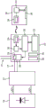
fig. 1A shows a first example of a lighting control module, a driver and a solid state light source together with an external interface device;
FIG. 1B illustrates an exemplary schematic circuit diagram of the lighting control module of FIG. 1A;
FIG. 2 illustrates an example of functionality that may be implemented by the lighting control module of FIG. 1;
FIG. 3 illustrates another example of functionality that may be implemented by the lighting control module of FIG. 1;
fig. 4 shows a second example of a lighting control module, a driver and a solid state light source together with an external interface device;
FIG. 5 illustrates an example of functionality that may be implemented by the lighting control module of FIG. 4; and
fig. 6 shows an example of the functionality that can be implemented by the rescaling unit of fig. 4.
Detailed Description
A lighting control module includes an interface for receiving dimming settings and a memory for storing the dimming settings. Based on the dimming setting, the output circuit generates a dimming control signal for application to a conventional dimming interface of the lighting driver circuit. To this end, power is received from the dimming interface. This provides an easy-to-use way to achieve controllable luminance, which makes use of dimming drivers, but for luminaires that need not be within a networked dimmable system architecture.
The dimming setting may be a wireless signal and a power harvesting circuit may be provided for harvesting power from the wireless interface to enable the memory to store the dimming setting.
Customers using modules to construct luminaires may desire to optimize the light output of their luminaires according to their preferences, without being limited to a fixed light output, temperature or power. For example, their own optical design may require less light output from the module. Alternatively, reduced power may be desirable to prevent the module from reaching excessive temperatures due to the use of miniaturized heat sinks.
It has been recognized that customers are expected to be able to flexibly set the output current. For example, the customer may insert a set resistor into the drive. The driver then uses this set resistor to define the output current.
An alternative to placing a current setting resistor in the driver is to allow a remotely settable drive current. For example, the drive may be programmed using a Near Field Communication (NFC) reader by using NFC. Philips (trade mark) issued a system operating in this manner, which was named the "SimpleSet" (trade mark) scope. This wireless programming technique allows luminaire manufacturers to quickly and easily program the LED drivers at any stage during the manufacturing process without connecting to mains power, which provides great flexibility.
With this "SimpleSet" system, the driver current is set via the driver and no additional components in the module are required. Thus, this solution is based on a new and upgraded driver design, and it is therefore particularly suitable for new lighting installations.
There are many existing driver types (fixed output, 1-10V dimming, DALI dimming, different power levels, etc.). In existing installations, it would be desirable to be able to achieve simplified light output control using existing drivers.
The present invention is based on using existing dimming interfaces to implement the dimming settings, but without using the wired infrastructure normally associated with dimming interfaces.
Fig. 1A shows a first example of a lighting control module 10 coupled to a lighting driver 12 with a coupling that includes a standard dimming interface 14. The driver may, for example, comprise terminals LED + and LED-for the lighting module 16 (i.e. the LED string), and separate pairs of wires forming the dimming interface 14.
In the example of fig. 1A, the driver 12 may be entirely conventional. Having a power unit for providing power to the lighting module 16, a controller for controlling the power applied by the power unit to the lighting module in accordance with commands received through the dimming interface.
This provides for the regulation of the power supply delivered to the lighting module.
These elements are standard parts of conventional drives and, therefore, they are not shown in fig. 1A. Indeed, the module 10 of this example of the invention is intended to be connectable to conventional drives.
The lighting module 10 comprises a controller in the form of a microprocessor 20 comprising a near field communication Integrated Circuit (IC), in particular an NFC reader, which converts NFC commands into signals for application to the dimming interface 14. The microprocessor has associated memory 22 and an NFC antenna 24 is present. The microprocessor also includes a power scavenging circuit 26 capable of extracting power from wireless communications to the module 10 for powering the microprocessor 20 and memory 22. Such self-powered near field communication systems, such as inductively powered RFID readers, are well known to those skilled in the art.
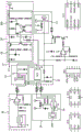
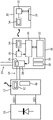
By way of example, fig. 1B shows a schematic circuit diagram of the module 10 of fig. 1A.
The microprocessor 20 in this example is a PIC12F1840 eight bit PIC @ microcontroller. However, it will be appreciated that other embodiments may employ any kind of smart device.
The microprocessor 20 functions as a control interface for receiving configuration information from an external configuration device. The external configuration device provides configuration information in the form of a dimming setting that is received by microprocessor 20. As shown in fig. 1A, external configuration device 30 includes an NFC IC 32, in particular an NFC transmitter, and an antenna 34. The user interface 36 enables a user to select a desired output flux, which is converted into a corresponding dimming setting.
Returning to FIG. 1B, the ADC channel 0 and 1 input pins of the microprocessor are connected to the data and clock pins, respectively, of the associated memory 22. The main clear pin of the microprocessor is connected to the main clear pin of the memory 22.
The NFC antenna 24 circuit (which in this example is a M24LR04E dynamic NFC/RFID tag integrated circuit with dual interface) is connected to the ADC channel 1 and 2 input pins of the microprocessor 20. More specifically, the serial clock SCL and serial data SDA pins of the NFC integrated circuit are connected to the ADC channel 1 and 2 input pins of the microprocessor 20, respectively. The antenna coil 24A is connected to the antenna coil AC0 and AC1 inputs of the NFC integrated circuit. The NFC integrated circuit also includes a power scavenging circuit 26 capable of extracting power from the wireless communication for powering the microprocessor 20 and the memory 22. The energy harvesting analog output pin a0 is used to deliver an analog voltage Vout that is available when the energy harvesting mode of the NFC integrated circuit is enabled and the RF field strength is sufficiently large.
The control interface (i.e. the NFC receiver of the microprocessor 20) is adapted to receive dimming settings from the external configuration device 30 before the module is driven by the connected driver, or during operation, such that the changes are allowed and adapted immediately during operation. This may be performed by the customer prior to installing the lighting system. NFC communication may be used to transfer the desired light output from external configuration device 30 to microprocessor 20 using wireless power transfer, without additional power being provided to the module. This may simply involve storing the value in the memory 22. The lighting module 10 needs to provide a signal to the dimming interface 14 only when the driver is powered.
The lighting control module may enable external dimming commands to be provided through the interface 15. Alternatively, it may operate in a pass-through mode for those commands, or it may be programmed to adapt them in the manner described below.
The lighting control module may include a temperature sensor 38 and/or an ambient light sensor 39 for additional functions described below. In the exemplary circuit of fig. 1B, a photosensor circuit 39 is depicted and connected to the data pin of memory 22 (along with the ADC channel 0 input pin of the microprocessor). Here, the light sensor circuit employs a NOA1212 low power ambient light sensor with an analog current output. The output of the NOA1212 ambient light sensor is fed to the memory via an amplifier (with feedback).
The power supply circuit 29 is used to power the output circuit 28 using power received from the dimming interface 14.
The output circuit/module 28 has a dual function, on the one hand, it has to create a low voltage supply for the electronic devices by means of the supply circuit 29. The analog input of the output module 28 may vary between 0V and 10V depending on the signal on the RA5 of the microprocessor. The lamp driver generates a voltage of 10V, which is limited in current when the current exceeds the maximum current level (typically about 150 uA) that the driver can create at this input, the voltage on the analog interface will drop. By drawing the right amount of current with the help of the input stage 28A, the voltage will drop to the desired level. This voltage level is also monitored in the lamp driver, which acts on it by varying its lamp power. If the input stage 28A draws more than 150uA and the voltage on the input also drops, the voltage to feed the electronics will drop. In this example, however, the voltage is not allowed to drop below, for example, 3V. This means that the output module 28A never draws more current than the current that allows the voltage to drop below 3V. With this 3V, the power supply circuit 29 is still able to provide sufficient power to power its own electronics (Vcc).
The module has a further dimming interface 15 so that even if the module is connected to the driver, the driver can still receive standard dimming commands over the conventional interface.
A first implementation will be described in more detail based on setting the appropriate light level of the luminaire using a conventional 1-10V analog dimming interface.
The lighting control module 10 can be powered by using a small current (e.g. 150 mua) produced by a 1-10V dimmable driver, which means that the module does not require its own power supply and can be kept compact and inexpensive. Such a module also allows several other functions, such as the actual time the storage facility is used, the number of times the facility is switched, etc. The use of the NFC protocol makes it possible to set and read these settings and data even if no power is applied to the luminaire.
A simple low power microprocessor 20 is used to read out the value of the NFC memory setting.
In a first implementation, the value from this memory 22 is used to set the voltage level of the 1-10V output to the appropriate dimming level.
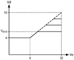
Fig. 2 shows an alternative where the dimming setting provided to the module 10 is used to limit the 1-10V input signal to a maximum setting based on the value in the memory location.
In this way, the luminaire may be part of a dimmable installation, but the range of output brightness levels is limited by the configuration. Thus, the use of the module does not prevent the dimming interface from being used to receive standard dimming signals within a dimmable architecture.
The various plots in fig. 2 show different transformations applicable to a dimming curve, which plots the output voltage Vd (y-axis) supplied to a standard dimming interface of the driver with respect to the external input Ve (x-axis). The maximum brightness is limited by limiting the output voltage Vd. For the 7 transformation curve shown in bold, the voltage is limited to VlimitSuch that, correspondingly, the light output is limited. The dashed curves show other possible transformation functions, where the highest level of output luminance is limited to a different level. High brightness corresponds to a high dimming value (e.g., 10V), while low brightness (i.e., deep dimming) corresponds to a low dimming value (e.g., 1V).
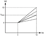
Another scheme is shown in fig. 3, where the dimming curve is readjusted so that the maximum output is limited again, instead of providing a capping function as in fig. 2, the full range Ve of the voltage to the external input, which can be processed (from 4V to 10V in this example), is readjusted from 4V to a limit value VlimitThe range of (1). The various plots in fig. 3 again show different transformations that may be applied to the dimming curve, which plots the output voltage Vd (y-axis) provided to the standard dimming interface of the driver relative to the external input Ve (x-axis). For the transformation curve shown in bold, the voltage is limited to VlimitBut this corresponds to an external input of 10V (rather than a lower input as in fig. 2). The dashed curves again show other possible transformation functions, where the highest level of output luminance is limited to a different level.
If the external voltage Ve is not supplied, the control module will simply set the output brightness level according to the value stored in the memory 22. This may be a value that has been programmed into memory, otherwise it may be a factory default value.
Note that the examples of fig. 2 and 3 are based on a control module that requires a 4V supply to operate, and in the case of an analogue dimming interface this sets the lowest voltage that can be supplied to the dimming interface.
The module may be extended with other useful functions, such as daylight adaptation based on integrated light sensors. If this functionality is added, the data in memory 22 of microprocessor 20 may be used to:
storing user-settable calibration data for daylight adaptation;
enable or disable daylight adaptation functions;
setting maximum and minimum dimming levels during daylight adaptation periods;
setting a daylight sensor sensitivity to adjust a daylight adaptation range;
setting whether the module uses specially defined or factory defined calibration settings for daylight adaptation functions or an auto-calibration routine;
the response time of the light adaptation control loop is set.
The module may also be used to read out information such as actual auto-calibration parameters of daylight sensors, or to read out historical dimming level information. Other manufacturer-related information may also be stored for readout, such as the date of manufacture, or information about the project in which the unit has been used, for easy traceability in case of field complaints.
The module may also enable other parameters to be read or configured, such as:
a manner in which the light level should rise after power up;
dimming curve shape of the module 10, e.g. dimming transformation function for correction driver;
the total operating time of the unit makes it possible to evaluate the lifetime of the LED board/driver.
This list is merely a small set of examples of additional functionality that may be incorporated.
In order to store or read different parameters in the NFC chip of a device, there are several known methods, such as a dedicated programmer that uses NFC to communicate. Alternatively, a dedicated smartphone application may be made that runs on an off-the-shelf smartphone equipped with an NFC chip.
Another set of examples may be based on a dimming interface using the DALI standard. If the driver is able to supply power to the interface bus, the module may again be powered from the DALI input of the lighting driver (this is allowed in the DALI 2.0 standard definition).
The microprocessor of the lighting control module may then be programmed so that a mirror image of several DALI memory blocks may be made available for programming and/or readout via the NFC interface. Due to the fact that the DALI interface bus is bidirectional and depends on the capabilities of the driver, several additional functions can be implemented, such as:
reading of power metering data of the drive (actual or aggregated over time);
manufacturer-related data stored in the DALI memory block;
DALI stores other contents of the block (as defined in IEC 62386).
The lighting control module may also include a temperature sensor, which may be used to set a maximum temperature or for the lifetime of the control module. The dimming level may be adjusted according to the temperature level. This can be used to program the module to remain below a maximum temperature, which can for example enable a guaranteed lifetime implementation.
Fig. 4 shows a modification of the system of fig. 1. In this case, an additional reconditioning unit 40 is present in the driver 12 and has an NFC communication interface as shown by antenna 42. Wireless communication also utilizes the configuration device 30. This arrangement is of particular interest for drivers with 1-10V dimming interfaces.
The input 14 to the driver 12 can receive a standard 1-10V interface (in which case the unit 40 operates in pass-through mode), or else it can receive a differently adjusted dimming curve from the module 10, and the unit 40 then performs a readjustment function.
As mentioned above, the lighting control module may be used to implement daylight adaptation functions. In some countries, new specifications and standards specify: if sufficient daylight is available, the window-facing luminaire must be dimmed. For stand-alone (non-networked) lighting systems, the requirement can be met, provided that the light output can be reduced to at most 35% of the original full output of the luminaire.
In the case of a 1-10V dimming interface, only a small amount of power is provided via the interface. The voltage supplied through the interface should then not drop below the typical operating voltage of the microprocessor. This is a problem because the same voltage lines of the 1-10V interface are used to derive the power of the module as is used to inform the driver of the dimming level. This may, for example, limit the lowest possible output voltage to the microcontroller operating voltage, which is typically in the range of 1.8V to 3V.
However, dimmable LED luminaires are then no longer dimmable from 10-100%. To be able to achieve this full range of dimming of the daylight adaptation system (which may be required by the specifications), the lighting control module would have to be able to operate powered by a 1V supply voltage. This makes it difficult to design an operating circuit based on low available power, based on a maximum current of about 150 mua.
This problem can be solved by redefining the dimming curve, e.g. such that the 10% level is reached at a voltage of about 2-4V and the maximum light output is reached at a dimming voltage level of 8-10V.
Using a redefined dimming curve in the driver would require an LED driver that no longer complies with the standard analog interface standard, which is undesirable. The system of fig. 4 alternatively provides conversion between the two interfaces. The rescaling unit 40 converts the input from the module (whose output is e.g. 4V-10V) into an interface signal of 1-10V. The rescaling unit 40 is able to override the standard dimming interface, which allows proper operation with the lighting control module. If the default interface settings stored in the rescaling unit 40 are compatible with the standard, the LED driver can still function as a 1-10V compatible dimmable driver. The driver can then also receive a conventional 1-10V dimming input at the same input 14, or otherwise a separate standard 1-10V interface may be provided in addition to the interface of the module 10.
The lighting control module 10 uses an adapted dimming curve that allows achieving a sufficiently high voltage at all dimming settings.
When sold in conjunction with an intelligent daylight sensor within the control module 10 as described above,
the dimming curves of both the driver and the lighting control module (which then acts as a sensor block) can then be adjusted using NFC tools in the form of a dedicated NFC configuration device 30, or NFC enabled smart phone and application.
The driver 12 has a standard 1-10V dimming behavior with a minimum arc power at 1V, a maximum arc power at 10V, and a boosted arc power between 1V and 10V.
The LED ballasts within the luminaires are factory pre-programmed with dimming level behavior, e.g. a minimum dimming level, such as 10%, for compliance with 1-10V analog dimming standards.
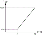
Fig. 5 illustrates voltage conversion performed by the lighting control module. It shows on the y-axis the voltage Vd supplied to the driver, which is in the range of 4 to 10V. The input to the lighting control module (i.e., the external voltage Ve supplied to the lighting control module) may be a standard 1-10V input as shown on the x-axis.
The lighting control module can only reduce its output voltage Vd to a voltage not lower than its own operating voltage, which in this example is 4V, for example. The minimum voltage may be below 4V, for example 3V or 1.8V.
By using the unit 40 to change the dimming curve (which may be set by means of NFC communication as explained above), the dimming behavior is changed in such a way: the minimum light level is achieved based on the operating voltage of the microprocessor, e.g. 1.8V.
Fig. 6 shows the function of the unit 40 and shows the transitions from the output Vd supplied to the driver (which corresponds to the y-axis of fig. 5), and then the applied LED current ILED。
In this way, the dimming curve of the ballast is matched to the output voltage of the control module, in this case 4V to 10V. The dimming level may be applied to the memory of the lighting control module and this may be used to set the dimming level to any value in the standard 10% to 100% range, even if the lighting control module is only able to output the lowest voltage of 1V lowest level above the 1-10V dimming interface.
The invention can be used in various lighting applications. The lighting module may be an indoor point light source, a down lighting unit, or a point lighting unit. The invention can also be used in linear LED applications (as used in offices) and also for outdoor lighting of roads and streets. In down-lighting and office systems, in general, a well-defined flux is required, making it highly desirable to easily implement a light output setting system. The invention can be used in intelligent lighting systems in office cubicles, meeting rooms, conference rooms, classrooms, hotel rooms and other hotel applications, as well as in various other indoor applications.
The invention has been described in connection with LED lighting arrangements. However, it may be applied to driver arrangements for other types of lighting technologies. For example, other solid state lighting technologies may be used.
The above example is based on wireless communication with the control module 10. This is preferred as it allows simple operation and also allows two-way communication. However, even simpler implementations are possible, where for example there is a manual input to the control module to input the dimming setting.
Other variations to the disclosed embodiments can be understood and effected by those skilled in the art in practicing the claimed invention, from a study of the drawings, the disclosure, and the appended claims. In the claims, the word "comprising" does not exclude other elements or steps, and the indefinite article "a" or "an" does not exclude a plurality. The mere fact that certain measures are recited in mutually different dependent claims does not indicate that a combination of these measures cannot be used to advantage. Any reference signs in the claims shall not be construed as limiting the scope.
Claims (12)
1. A lighting control module, comprising:
an interface (20, 24) for receiving a dimming setting;
a memory (22) for storing the dimming settings;
an output circuit (28) for generating a dimming control signal for application to an external dimming interface (14) of a lighting driver circuit (12) based on the dimming setting stored in the memory (22) and a measured ambient light level; and
a power supply circuit (29) for powering the output circuit (28) based on power received from the external dimming interface (14) of the lighting driver circuit, wherein the dimming setting is for processing an externally input dimming setting to readjust a dimming function.
2. The lighting control module of claim 1, wherein the interface is a wireless interface for receiving a wireless dimming setting signal, wherein the control module (10) comprises an NFC antenna (24), an NFC receiver (20), and a power scavenging circuit (26), the power scavenging circuit (26) for scavenging power from the wireless interface to enable the memory to store the dimming setting.
3. The lighting control module of claim 1 or 2, comprising a physical output connector for connection to the lighting driver circuit.
4. The lighting control module of claim 1, wherein the dimming control signal comprises a DALI signal.
5. The lighting control module of claim 4, wherein the memory (22) is adapted to store further DALI settings.
6. The lighting control module of claim 1, wherein the dimming control signal comprises a 1-10V signal.
7. An illumination system, comprising:
the lighting control module of any preceding claim; and
a lighting driver circuit (12) comprising a dimming interface (14), a dimming control signal being applied to the dimming interface (14).
8. The lighting system of claim 7, wherein the dimming interface is a 1-10V dimming interface capable of receiving a standard 1-10V dimming signal,
wherein the dimming control signal of the lighting control module has a first range of voltage values having a lowest value greater than 1V,
and wherein the lighting driver circuit comprises a re-adjustment unit (40) for re-adjusting the dimming control signal to form a 1-10V signal.
9. The lighting system of claim 8, wherein the rescale unit comprises a wireless interface for receiving a rescale command.
10. The lighting system of any of claims 7 to 9, further comprising a configuration device for wirelessly transmitting the dimming setting to the lighting control module.
11. A method of setting a dimming level of a lighting system comprising a lighting driver (12) having a dimming interface (14), the method comprising:
connecting a lighting control module (10) to the dimming interface;
sending a dimming setting from a configuration device (30) to the lighting control module;
storing the dimming settings in the lighting control module;
powering the lighting control module and reading the stored dimming settings using power provided by a lighting driver to the dimming interface; and
setting, within the lighting driver, the dimming level based on the stored dimming setting and the measured ambient light level,
wherein the dimming setting is used to process an externally input dimming setting to readjust the dimming function.
12. The method of claim 11, further comprising, in the lighting driver, readjusting the dimming settings read from the lighting control module to form a 1-10V dimming control signal.
Applications Claiming Priority (3)
| Application Number | Priority Date | Filing Date | Title |
|---|---|---|---|
| EP15165255 | 2015-04-27 | ||
| EP15165255.9 | 2015-04-27 | ||
| PCT/EP2016/057975 WO2016173832A1 (en) | 2015-04-27 | 2016-04-12 | A lighting control module, a lighting system using the same and a method of setting a dimming level |
Publications (2)
| Publication Number | Publication Date |
|---|---|
| CN107637178A CN107637178A (en) | 2018-01-26 |
| CN107637178B true CN107637178B (en) | 2020-01-17 |
Family
ID=53015608
Family Applications (1)
| Application Number | Title | Priority Date | Filing Date |
|---|---|---|---|
| CN201680024801.9A Active CN107637178B (en) | 2015-04-27 | 2016-04-12 | Lighting control module, lighting system using the same, and method of setting dimming level |
Country Status (6)
| Country | Link |
|---|---|
| US (1) | US10448488B2 (en) |
| EP (1) | EP3289827B1 (en) |
| JP (1) | JP6704927B2 (en) |
| CN (1) | CN107637178B (en) |
| RU (1) | RU2713399C2 (en) |
| WO (1) | WO2016173832A1 (en) |
Families Citing this family (8)
| Publication number | Priority date | Publication date | Assignee | Title |
|---|---|---|---|---|
| CN106658873B (en) * | 2017-02-28 | 2018-06-05 | 横店集团得邦照明股份有限公司 | A kind of light color adjustable LED control system based on nonlinear closed loop |
| EP3653023A2 (en) | 2017-07-14 | 2020-05-20 | Lutron Technology Company LLC | Configuration for a load regulation device for lighting control |
| JP7051496B2 (en) * | 2018-03-06 | 2022-04-11 | 株式会社アイ・ライティング・システム | Power supply for lighting with variable parameters |
| CN112689353B (en) * | 2018-11-02 | 2024-02-09 | 中国计量大学 | Lighting control method for guest room of business hotel |
| US11051373B2 (en) * | 2019-09-06 | 2021-06-29 | Robe Lighting S.R.O. | Removable LED module with rotated LED emitter groups |
| US11966213B2 (en) * | 2020-08-03 | 2024-04-23 | Abl Ip Holding Llc | Handheld programmer for LED drivers |
| CN113669664A (en) * | 2021-08-23 | 2021-11-19 | 江苏新广联光电股份有限公司 | Healthy intelligent lighting system in classroom |
| WO2024005674A1 (en) * | 2022-06-27 | 2024-01-04 | Общество с ограниченной ответственностью "Совтест - техно" | Street light telemetry and control device |
Citations (2)
| Publication number | Priority date | Publication date | Assignee | Title |
|---|---|---|---|---|
| WO2012176097A1 (en) * | 2011-06-21 | 2012-12-27 | Koninklijke Philips Electronics N.V. | Lighting apparatus and method using multiple dimming schemes |
| US20140001962A1 (en) * | 2012-07-01 | 2014-01-02 | Cree, Inc. | Modular lighting control |
Family Cites Families (30)
| Publication number | Priority date | Publication date | Assignee | Title |
|---|---|---|---|---|
| DE19757295B4 (en) | 1997-03-04 | 2005-08-04 | Tridonicatco Gmbh & Co. Kg | Electronic ballast |
| WO2001099477A1 (en) * | 2000-06-20 | 2001-12-27 | Koninklijke Philips Electronics N.V. | Circuit device |
| DE60320545T2 (en) * | 2002-03-26 | 2008-10-23 | Koninklijke Philips Electronics N.V. | INTERFACE FOR DIGITAL COMMUNICATION |
| EP1741317A1 (en) * | 2004-04-15 | 2007-01-10 | Koninklijke Philips Electronics N.V. | Mains wire antenna for wireless interface applications |
| ES2841050T3 (en) * | 2006-06-02 | 2021-07-07 | Signify Holding Bv | Lamp control circuit to drive a lamp |
| US8072164B2 (en) * | 2008-10-28 | 2011-12-06 | General Electric Company | Unified 0-10V and DALI dimming interface circuit |
| RU2538786C2 (en) * | 2009-01-29 | 2015-01-10 | Конинклейке Филипс Электроникс, Н.В. | Light control system reacting to ambient illumination conditions |
| WO2011083394A1 (en) * | 2010-01-06 | 2011-07-14 | Koninklijke Philips Electronics N.V. | Adaptable lighting system |
| CN102348927B (en) | 2010-03-30 | 2013-12-18 | 建兴电子科技股份有限公司 | Light programmable apparatus with light programmable lamp |
| WO2012021660A1 (en) * | 2010-08-10 | 2012-02-16 | Accenture Global Services Limited | Sales and operations planning interface tool |
| WO2012021060A2 (en) | 2010-08-12 | 2012-02-16 | Eldolab Holding B.V. | Interface circuit for a lighting device |
| EP2664840A4 (en) * | 2011-01-12 | 2014-09-17 | Livingstyle Entpr Ltd | Induction lighting apparatus having electromagnetic wave wireless communication module and control method applied in same |
| US9801261B2 (en) * | 2012-01-05 | 2017-10-24 | Bright Light Systems, Inc. | Systems and methods for providing high-mast lighting |
| KR101664158B1 (en) * | 2012-01-18 | 2016-10-11 | 인텔 코포레이션 | Intelligent computational imaging system |
| WO2013142292A1 (en) * | 2012-03-19 | 2013-09-26 | Digital Lumens Incorporated | Methods, systems, and apparatus for providing variable illumination |
| JP2015528151A (en) | 2012-06-14 | 2015-09-24 | コーニンクレッカ フィリップス エヌ ヴェ | Apparatus and method for collecting and using operational data from lighting products |
| JP6049357B2 (en) * | 2012-08-30 | 2016-12-21 | ミネベア株式会社 | LED driving device and lighting apparatus |
| US9155166B2 (en) * | 2012-12-18 | 2015-10-06 | Cree, Inc. | Efficient routing tables for lighting networks |
| US10019047B2 (en) * | 2012-12-21 | 2018-07-10 | Lutron Electronics Co., Inc. | Operational coordination of load control devices for control of electrical loads |
| EP2770804B1 (en) * | 2013-02-26 | 2020-07-15 | Nxp B.V. | Lighting control method, computer program product and lighting control system |
| CA2907633A1 (en) * | 2013-03-27 | 2014-10-02 | Schreder | Dual-mode luminaire controllers |
| EP3028542A1 (en) * | 2013-07-30 | 2016-06-08 | Koninklijke Philips N.V. | Apparatus for driving load via converter |
| PT3036976T (en) * | 2013-08-19 | 2020-01-20 | Signify Holding Bv | Programmable lighting device and method and system for programming lighting device |
| JP6155985B2 (en) * | 2013-08-30 | 2017-07-05 | 東芝ライテック株式会社 | LIGHTING DEVICE, LIGHTING SYSTEM, AND CONTROL METHOD |
| CA2931526C (en) * | 2013-11-25 | 2022-04-19 | Abl Ip Holding Llc | System and method for communication with a mobile device via a positioning system including rf communication devices and modulated beacon light sources |
| CN107637177A (en) * | 2015-04-21 | 2018-01-26 | 飞利浦照明控股有限公司 | Illuminator |
| US9974147B1 (en) * | 2015-08-10 | 2018-05-15 | Universal Lighting Technologies, Inc. | Integrated LED driver for wireless communication |
| US9648697B1 (en) * | 2016-04-19 | 2017-05-09 | Leviton Manufacturing Co., Inc. | Brightness monitoring for LED failures and daylighting target adjusting |
| US9848480B1 (en) * | 2016-06-14 | 2017-12-19 | Honeywell International Inc. | Lightbulb in a fixture having a configuration memory |
| US9997070B1 (en) * | 2017-05-18 | 2018-06-12 | Abl Ip Holding Llc | Use of software configurable luminaire in parking application |
-
2016
- 2016-04-12 US US15/569,944 patent/US10448488B2/en active Active
- 2016-04-12 WO PCT/EP2016/057975 patent/WO2016173832A1/en active Application Filing
- 2016-04-12 EP EP16716036.5A patent/EP3289827B1/en active Active
- 2016-04-12 RU RU2017140988A patent/RU2713399C2/en active
- 2016-04-12 JP JP2017549323A patent/JP6704927B2/en active Active
- 2016-04-12 CN CN201680024801.9A patent/CN107637178B/en active Active
Patent Citations (2)
| Publication number | Priority date | Publication date | Assignee | Title |
|---|---|---|---|---|
| WO2012176097A1 (en) * | 2011-06-21 | 2012-12-27 | Koninklijke Philips Electronics N.V. | Lighting apparatus and method using multiple dimming schemes |
| US20140001962A1 (en) * | 2012-07-01 | 2014-01-02 | Cree, Inc. | Modular lighting control |
Also Published As
| Publication number | Publication date |
|---|---|
| WO2016173832A1 (en) | 2016-11-03 |
| RU2017140988A3 (en) | 2019-11-13 |
| RU2713399C2 (en) | 2020-02-05 |
| EP3289827A1 (en) | 2018-03-07 |
| US20180160511A1 (en) | 2018-06-07 |
| US10448488B2 (en) | 2019-10-15 |
| CN107637178A (en) | 2018-01-26 |
| JP2018518007A (en) | 2018-07-05 |
| RU2017140988A (en) | 2019-05-27 |
| EP3289827B1 (en) | 2020-11-18 |
| JP6704927B2 (en) | 2020-06-03 |
Similar Documents
| Publication | Publication Date | Title |
|---|---|---|
| CN107637178B (en) | Lighting control module, lighting system using the same, and method of setting dimming level | |
| EP3259959B1 (en) | A solid state lighting module, a lighting circuit and lighting control methods. | |
| US9795013B2 (en) | Wireless lighting control | |
| US20150084503A1 (en) | Pluggable Control Module For LED Lighting Device | |
| EP3022993B1 (en) | Methods and apparatus for controlling lighting based on combination of inputs | |
| US20110276193A1 (en) | Energy efficient lighting system | |
| CN106664755A (en) | Radio frequency (rf) controlled lamp with dimmer compatibility | |
| CN111418267B (en) | Arrangement of load adjusting device for lighting control | |
| US10448487B2 (en) | Driver module for powering a light source and a further module | |
| EP3086624A1 (en) | A solid state lighting module, a lighting circuit and lighting control methods | |
| US10779382B2 (en) | Semiconductor device for outputting a control parameter | |
| CN210405713U (en) | Illumination control system | |
| CN110073725B (en) | Assembly and method for controlling an electronic device | |
| JP6705349B2 (en) | Lighting system, plant growing lighting system, lighting equipment | |
| US20210014952A1 (en) | System and method for automated light level and daylight harvesting calibration using mobile handheld devices | |
| WO2017222825A1 (en) | System and method for automated light level and daylight harvesting calibration using mobile handheld devices | |
| JP2017130396A (en) | Luminaire |
Legal Events
| Date | Code | Title | Description |
|---|---|---|---|
| PB01 | Publication | ||
| PB01 | Publication | ||
| SE01 | Entry into force of request for substantive examination | ||
| SE01 | Entry into force of request for substantive examination | ||
| GR01 | Patent grant | ||
| GR01 | Patent grant | ||
| CP03 | Change of name, title or address |
Address after: Eindhoven Patentee after: Signify Holdings Ltd. Address before: Eindhoven, the Netherlands Patentee before: PHILIPS LIGHTING HOLDING B.V. |
|
| CP03 | Change of name, title or address |