CN107533498B - Vehicle control device - Google Patents
Vehicle control device Download PDFInfo
- Publication number
- CN107533498B CN107533498B CN201680025163.2A CN201680025163A CN107533498B CN 107533498 B CN107533498 B CN 107533498B CN 201680025163 A CN201680025163 A CN 201680025163A CN 107533498 B CN107533498 B CN 107533498B
- Authority
- CN
- China
- Prior art keywords
- control
- travel
- mode
- vehicle
- control mode
- Prior art date
- Legal status (The legal status is an assumption and is not a legal conclusion. Google has not performed a legal analysis and makes no representation as to the accuracy of the status listed.)
- Active
Links
- 230000007704 transition Effects 0.000 claims abstract description 21
- 238000012544 monitoring process Methods 0.000 claims description 5
- 230000002159 abnormal effect Effects 0.000 claims 1
- 230000001052 transient effect Effects 0.000 abstract description 6
- 238000010586 diagram Methods 0.000 description 24
- 238000000034 method Methods 0.000 description 20
- 238000011084 recovery Methods 0.000 description 19
- 238000012545 processing Methods 0.000 description 16
- 230000015556 catabolic process Effects 0.000 description 15
- 238000006731 degradation reaction Methods 0.000 description 15
- 230000008569 process Effects 0.000 description 15
- 230000006870 function Effects 0.000 description 13
- 230000008859 change Effects 0.000 description 7
- 238000012805 post-processing Methods 0.000 description 4
- 230000000737 periodic effect Effects 0.000 description 3
- 239000013589 supplement Substances 0.000 description 3
- 230000007850 degeneration Effects 0.000 description 2
- 230000001771 impaired effect Effects 0.000 description 2
- 230000007246 mechanism Effects 0.000 description 2
- 230000004048 modification Effects 0.000 description 2
- 238000012986 modification Methods 0.000 description 2
- 230000008901 benefit Effects 0.000 description 1
- JJWKPURADFRFRB-UHFFFAOYSA-N carbonyl sulfide Chemical compound O=C=S JJWKPURADFRFRB-UHFFFAOYSA-N 0.000 description 1
- 238000012790 confirmation Methods 0.000 description 1
- 238000010276 construction Methods 0.000 description 1
- 238000013461 design Methods 0.000 description 1
- 238000001514 detection method Methods 0.000 description 1
- 230000000694 effects Effects 0.000 description 1
- 238000004519 manufacturing process Methods 0.000 description 1
- 238000004092 self-diagnosis Methods 0.000 description 1
- 239000007787 solid Substances 0.000 description 1
Images


Classifications
-
- G—PHYSICS
- G05—CONTROLLING; REGULATING
- G05D—SYSTEMS FOR CONTROLLING OR REGULATING NON-ELECTRIC VARIABLES
- G05D1/00—Control of position, course, altitude or attitude of land, water, air or space vehicles, e.g. using automatic pilots
- G05D1/0055—Control of position, course, altitude or attitude of land, water, air or space vehicles, e.g. using automatic pilots with safety arrangements
- G05D1/0066—Control of position, course, altitude or attitude of land, water, air or space vehicles, e.g. using automatic pilots with safety arrangements for limitation of acceleration or stress
-
- G—PHYSICS
- G06—COMPUTING; CALCULATING OR COUNTING
- G06F—ELECTRIC DIGITAL DATA PROCESSING
- G06F11/00—Error detection; Error correction; Monitoring
- G06F11/07—Responding to the occurrence of a fault, e.g. fault tolerance
- G06F11/0703—Error or fault processing not based on redundancy, i.e. by taking additional measures to deal with the error or fault not making use of redundancy in operation, in hardware, or in data representation
- G06F11/0706—Error or fault processing not based on redundancy, i.e. by taking additional measures to deal with the error or fault not making use of redundancy in operation, in hardware, or in data representation the processing taking place on a specific hardware platform or in a specific software environment
- G06F11/0721—Error or fault processing not based on redundancy, i.e. by taking additional measures to deal with the error or fault not making use of redundancy in operation, in hardware, or in data representation the processing taking place on a specific hardware platform or in a specific software environment within a central processing unit [CPU]
- G06F11/0724—Error or fault processing not based on redundancy, i.e. by taking additional measures to deal with the error or fault not making use of redundancy in operation, in hardware, or in data representation the processing taking place on a specific hardware platform or in a specific software environment within a central processing unit [CPU] in a multiprocessor or a multi-core unit
-
- G—PHYSICS
- G06—COMPUTING; CALCULATING OR COUNTING
- G06F—ELECTRIC DIGITAL DATA PROCESSING
- G06F11/00—Error detection; Error correction; Monitoring
- G06F11/07—Responding to the occurrence of a fault, e.g. fault tolerance
- G06F11/0703—Error or fault processing not based on redundancy, i.e. by taking additional measures to deal with the error or fault not making use of redundancy in operation, in hardware, or in data representation
- G06F11/0706—Error or fault processing not based on redundancy, i.e. by taking additional measures to deal with the error or fault not making use of redundancy in operation, in hardware, or in data representation the processing taking place on a specific hardware platform or in a specific software environment
- G06F11/0736—Error or fault processing not based on redundancy, i.e. by taking additional measures to deal with the error or fault not making use of redundancy in operation, in hardware, or in data representation the processing taking place on a specific hardware platform or in a specific software environment in functional embedded systems, i.e. in a data processing system designed as a combination of hardware and software dedicated to performing a certain function
- G06F11/0739—Error or fault processing not based on redundancy, i.e. by taking additional measures to deal with the error or fault not making use of redundancy in operation, in hardware, or in data representation the processing taking place on a specific hardware platform or in a specific software environment in functional embedded systems, i.e. in a data processing system designed as a combination of hardware and software dedicated to performing a certain function in a data processing system embedded in automotive or aircraft systems
-
- G—PHYSICS
- G06—COMPUTING; CALCULATING OR COUNTING
- G06F—ELECTRIC DIGITAL DATA PROCESSING
- G06F11/00—Error detection; Error correction; Monitoring
- G06F11/07—Responding to the occurrence of a fault, e.g. fault tolerance
- G06F11/16—Error detection or correction of the data by redundancy in hardware
- G06F11/20—Error detection or correction of the data by redundancy in hardware using active fault-masking, e.g. by switching out faulty elements or by switching in spare elements
- G06F11/202—Error detection or correction of the data by redundancy in hardware using active fault-masking, e.g. by switching out faulty elements or by switching in spare elements where processing functionality is redundant
- G06F11/2023—Failover techniques
-
- G—PHYSICS
- G06—COMPUTING; CALCULATING OR COUNTING
- G06F—ELECTRIC DIGITAL DATA PROCESSING
- G06F11/00—Error detection; Error correction; Monitoring
- G06F11/30—Monitoring
- G06F11/3003—Monitoring arrangements specially adapted to the computing system or computing system component being monitored
- G06F11/3013—Monitoring arrangements specially adapted to the computing system or computing system component being monitored where the computing system is an embedded system, i.e. a combination of hardware and software dedicated to perform a certain function in mobile devices, printers, automotive or aircraft systems
-
- G—PHYSICS
- G06—COMPUTING; CALCULATING OR COUNTING
- G06F—ELECTRIC DIGITAL DATA PROCESSING
- G06F11/00—Error detection; Error correction; Monitoring
- G06F11/30—Monitoring
- G06F11/3003—Monitoring arrangements specially adapted to the computing system or computing system component being monitored
- G06F11/302—Monitoring arrangements specially adapted to the computing system or computing system component being monitored where the computing system component is a software system
-
- G—PHYSICS
- G06—COMPUTING; CALCULATING OR COUNTING
- G06F—ELECTRIC DIGITAL DATA PROCESSING
- G06F11/00—Error detection; Error correction; Monitoring
- G06F11/30—Monitoring
- G06F11/34—Recording or statistical evaluation of computer activity, e.g. of down time, of input/output operation ; Recording or statistical evaluation of user activity, e.g. usability assessment
- G06F11/3466—Performance evaluation by tracing or monitoring
- G06F11/3495—Performance evaluation by tracing or monitoring for systems
-
- G—PHYSICS
- G07—CHECKING-DEVICES
- G07C—TIME OR ATTENDANCE REGISTERS; REGISTERING OR INDICATING THE WORKING OF MACHINES; GENERATING RANDOM NUMBERS; VOTING OR LOTTERY APPARATUS; ARRANGEMENTS, SYSTEMS OR APPARATUS FOR CHECKING NOT PROVIDED FOR ELSEWHERE
- G07C5/00—Registering or indicating the working of vehicles
- G07C5/08—Registering or indicating performance data other than driving, working, idle, or waiting time, with or without registering driving, working, idle or waiting time
- G07C5/0808—Diagnosing performance data
Landscapes
- Engineering & Computer Science (AREA)
- Theoretical Computer Science (AREA)
- Physics & Mathematics (AREA)
- General Physics & Mathematics (AREA)
- General Engineering & Computer Science (AREA)
- Quality & Reliability (AREA)
- Computing Systems (AREA)
- Mathematical Physics (AREA)
- Aviation & Aerospace Engineering (AREA)
- Radar, Positioning & Navigation (AREA)
- Remote Sensing (AREA)
- Automation & Control Theory (AREA)
- Computer Hardware Design (AREA)
- Control Of Driving Devices And Active Controlling Of Vehicle (AREA)
- Control Of Position, Course, Altitude, Or Attitude Of Moving Bodies (AREA)
- Hardware Redundancy (AREA)
- Electric Propulsion And Braking For Vehicles (AREA)
Abstract
Provided is a vehicle control device which can alleviate a control level difference generated when a failure is repaired and a system is restored to a normal state, and can provide smooth drivability to a user. The vehicle control device of the present invention has a1 st travel control mode and a 2 nd travel control mode, and in a transient state during transition from the 2 nd travel control mode to the 1 st travel control mode, calculates and checks a1 st control parameter in the 1 st travel control mode, and calculates and uses a 2 nd control parameter in the 2 nd travel control mode for travel control.
Description
Technical Field
The present invention relates to a vehicle control device.
Background
In electric devices such as automobiles, elevators, and construction machines, embedded control devices are used which control a control target by so-called embedded software. Embedded software has the advantage of enabling flexible and high-level control over conventional control schemes using mechanical mechanisms and circuits.
In an embedded Control device (for example, a vehicle Control device), in order to reduce a vehicle-mounted space and a manufacturing cost, an ECU (Electronic Control Unit) in which functions mounted on respective ECUs are collected into 1 ECU has been conventionally integrated. In the process of integrating the ECUs, it is necessary to handle a plurality of functions on the same ECU. Therefore, in the vehicle control device, the multicore processor is started to be flexibly used.
The multi-core processor can perform each process in parallel using a plurality of cores, and can replace application software allocated to a part of cores with another core when the part of cores has a failure. This makes it possible to achieve redundancy of the system and improve safety.
Documents of the prior art
Patent document
Patent document 1: japanese patent laid-open publication No. 2010-020621
Disclosure of Invention
Problems to be solved by the invention
When the technique described in patent document 1 is used in an embedded control device of an automobile or the like, a core having a failure may lose historical data in a program in which the core is performing arithmetic processing, and a large control level difference may occur before and after the core is returned to a normal state. The history data in the program is data that is continuously updated based on, for example, the operation results of the integrator and the differentiator, the state amount in the system, and the like.
More specifically, when a failure in a core of a multi-core processor is detected during the running control of an automobile, even if the failed core is restored using the technique described in patent document 1 and the system is restored to a normal state, the history data in the program is lost, and therefore, there is a possibility that a discontinuity in the control occurs and the comfort of driving is impaired.
The present invention has been made in view of the above problems, and an object of the present invention is to provide a vehicle control device capable of alleviating a control level difference generated when a failure is repaired and a system is restored to a normal state, and providing smooth drivability to a user.
Means for solving the problems
The vehicle control device of the present invention has a1 st travel control mode and a 2 nd travel control mode, and in a transient state during transition from the 2 nd travel control mode to the 1 st travel control mode, calculates and checks a1 st control parameter in the 1 st travel control mode, and calculates and uses a 2 nd control parameter in the 2 nd travel control mode for travel control.
Effects of the invention
According to the vehicle control device of the present invention, smooth drivability can be provided to the user by reducing the control level difference.
Drawings
Fig. 1 is a system configuration diagram of a vehicle control device 1 according to embodiment 1.
Fig. 2 is a state transition diagram showing an operation of a vehicle control device according to the related art.
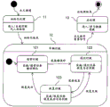
Fig. 3 is a state transition diagram showing an operation of the vehicle control device 1 according to embodiment 1.
Fig. 4 is a diagram showing a state in which the vehicle control device 1 implements the normal travel mode 121.
Fig. 5 is a diagram showing a state in which the vehicle control device 1 implements the degraded running mode 122.
Fig. 6 is a diagram showing a state in which the vehicle control device 1 performs the return to the running mode 123.
Fig. 7 is a flowchart illustrating a procedure in which the vehicle control device 1 performs the return to the running mode 123.
Fig. 8 is a diagram showing a change with time in an output value of a vehicle control device according to the related art.
Fig. 9 is a diagram showing a change with time in the output value output from the vehicle control device 1 via the input/output unit 140.
Fig. 10 is a diagram showing a change with time in power consumption of the vehicle control device 1.
Fig. 11 is a system configuration diagram of the vehicle control device 1 according to embodiment 2.
Fig. 12 is a system configuration diagram of the vehicle control device 1 according to embodiment 3.
Fig. 13 is a state transition diagram showing an operation of the vehicle control device 1 according to embodiment 4.
Detailed Description
< embodiment 1>
Fig. 1 is a system configuration diagram of a vehicle control device 1 according to embodiment 1 of the present invention. The vehicle control device 1 is a device that controls the operation of a vehicle. The vehicle control device 1 includes a processor 110, a normal control program 120, a degradation control program 130, and an input/output unit 140. The processor 110 is a multicore processor, and includes a core (core) a111 and a core B112.
Core a111 executes the normal control program 120, and core B112 executes the degeneration control program 130. The input/output unit 140 receives a signal from a sensor or the like disposed outside the vehicle control device 1, transits the signal to the processor 110, and receives a control signal from the processor 110 and outputs the signal to a control target.
The normal control program 120 is a program in which control processing to be executed by the processor 110 during normal running of the vehicle is installed. The degradation control program 130 is a program in which control processing to be executed by the processor 110 when the vehicle travels with degradation is installed. The degraded running is running in a state where the function of the vehicle is degraded due to, for example, an error found during normal running.
Fig. 2 is a state transition diagram showing an operation of a conventional vehicle control device. In general, a vehicle travels by operating an actuator such as a motor in accordance with an output value output from a vehicle control device. When the ignition (ignition) is turned ON (ON), the vehicle control apparatus shifts to the initialization processing mode 11.
In the initialization processing mode 11, the vehicle control device starts self-diagnosis and performs initialization processing of substituting a predetermined variable with an initial value or the like. When these initialization processes are completed, the vehicle control device shifts to the vehicle travel mode 12, and the vehicle is in a state where the vehicle can actually travel.
When the vehicle control device shifts to the vehicle travel mode 12, the vehicle control device first enters the normal travel mode 121 state. In the normal travel mode 121, the vehicle control device performs the following processes: (a) executing a periodic task of arithmetic processing every fixed period; (b) an aperiodic task for executing arithmetic processing at a timing such as engine rotation; (c) and an error check for monitoring the occurrence of an error in the vehicle control device. Each task includes a process of calculating a control parameter for operating the vehicle in the normal travel mode 121. When an error is found in the normal running mode 121, the vehicle control device shifts to the degraded running mode 122. Here, the error is a state in which the possibility of danger to the user is high to some extent when the normal running is continued.
The degraded driving mode 122 is a safety mechanism required by safety standards such as ISO 26262. In the degraded running mode 122, even if an error of the vehicle control apparatus is confirmed, the vehicle control apparatus continues the control of the vehicle by performing the continuous arithmetic processing on the minimum necessary function without suddenly stopping the control function. In the degraded running mode 122, the vehicle control device implements a periodic/aperiodic task for performing degraded running. Each task includes a process of calculating a control parameter for operating the vehicle in the degraded running mode 122.
If the ignition is turned OFF (OFF) in the state of the vehicle travel mode 12, or if a signal to reset the vehicle control apparatus is issued in the state of the vehicle travel mode 12, the vehicle control apparatus transitions to the post-processing mode 13.
In the post-processing mode 13, the vehicle control device saves learning data required next time the ignition is turned on to the nonvolatile memory. When the post-processing is completed, the vehicle control device stops the function and the vehicle is also stopped.
The vehicle control device implements the state transition described above, thereby realizing the traveling of the vehicle. When an error is found in the normal running mode 121 and the vehicle shifts to the degraded running mode 122, the entire system of the vehicle control device needs to be restarted in order to shift to the normal running mode 121 again, turn off the ignition, issue a reset signal, or the like. Therefore, the control parameter intermittently changes before and after the restart, and there is a possibility that smooth drivability may be prevented.
Fig. 3 is a state transition diagram showing an operation of the vehicle control device 1 according to embodiment 1. In fig. 3, compared with fig. 2, the return travel mode 123 is newly provided. In fig. 2, it is necessary to turn on the ignition or the like in order to return from the degraded running mode 122 to the normal running mode, but in the present embodiment, the return to the normal state is smoothly achieved without interrupting the control parameters by returning from the degraded running mode 122 to the normal running mode 121 via the return running mode 123.
In the degraded running mode 122 of embodiment 1, the vehicle control device 1 determines whether or not the transition to the recovery running mode 123 is necessary, and therefore performs the determination as to whether or not the recovery is necessary. As a trigger for determining whether to return to the normal running mode, there are various triggers, and for example, a predetermined time has elapsed after the transition to the degraded running mode 122.
In the resume running mode 123, the vehicle control device 1 implements a periodic/aperiodic task for implementing the resume running. In the recovery travel mode 123, a determination is made as to whether the recovery is successful or not to make a decision as to whether to shift the vehicle to the normal travel mode 121 or to return to the degraded travel mode 122. The details of the recovery success or failure determination are discussed later. By providing the return travel mode 123, even if the vehicle control device 1 detects an error, the vehicle control device can return to the normal travel mode 121 without restarting the entire vehicle.
Fig. 4 is a diagram showing a state in which the vehicle control device 1 implements the normal travel mode 121. In the normal travel mode 121, the core a111 executes the normal control program 120, and outputs a control signal using an output value thereof as a control parameter via the input/output unit 140 to control the vehicle. The normal control program 120 is a control program in which a normal task and an error confirmation process in the normal travel mode 121 are installed. The core a111 may simultaneously execute processing other than the normal control program 120.
Fig. 5 is a diagram showing a state in which the vehicle control device 1 implements the degraded running mode 122. The degraded running mode 122 is executed when, for example, the core a111 has a failure and the core a111 cannot execute the normal control program 120. The core B112 executes the degradation control program 130 instead of the normal control program 120, and outputs a control signal using an output value thereof as a control parameter via the input/output unit 140 to control the vehicle. The degradation control program 130 is provided with a degradation task and a recovery or non-recovery determination process in the degradation running mode 122. The core B112 may simultaneously execute processing other than the degradation control program 130.
Fig. 6 is a diagram showing a state in which the vehicle control device 1 performs the return to the running mode 123. In the recovery travel mode 123, the core a111 (detecting a failure) executes the normal control program 120, and in parallel with this, the core B112 executes the degradation control program 130.
In the resume running mode 123, the processor 110 controls the vehicle using the output value of the degradation control program 130 executed by the core B112 as a control parameter in order to ensure safety without using the output value of the core a111 for vehicle control. However, by executing the normal control program 120, calculating and checking the control parameters, it is possible to determine whether or not the error found in the normal travel mode 121 is a transient error.
In the recovery running mode 123, when an error is reproduced in the normal running mode 121, it is assumed that a permanent fault such as a short circuit occurs because the error is not a transient error, and the recovery is determined to have failed in the recovery success/failure determination process, and the routine returns to the degraded running mode 122. If the error found in the normal travel mode 121 is not reproduced, it is assumed that a transient fault due to a cosmic ray or the like occurs, and the recovery success determination process determines that the recovery is successful, and the routine can transition to the normal travel mode 121.
Fig. 7 is a flowchart illustrating a procedure in which the vehicle control device 1 performs the return to the running mode 123. The steps in fig. 7 will be explained below.
(FIG. 7: Steps S12301 to S12302)
The processor 110 restarts only the core a111 in which the error is detected in the normal travel mode 121 (S12301). The core a111 executes the normal control program 120 (S12302). However, as described above, the output value obtained by executing the normal control routine 120 is not used for vehicle control.
(FIG. 7: step S12303)
The processor 110 confirms whether the output value of the normal control program 120 executed by the core a111 is normal. For example, upper and lower limit values that can be obtained by the control parameters calculated by the normal control program 120 are defined in advance, and a determination method is considered that if the output value is within a predetermined time or more, the output value is regarded as normal. As long as the output value is normal, the error found in the normal travel mode 121 is regarded as a transient error, and the process proceeds to step S12304. Otherwise, the process proceeds to step S12306, where it is determined as a permanent error.
(FIG. 7: step S12304)
The processor 110 determines whether the output value of the normal control program 120 executed by the core a111 and the output value of the degeneration control program 130 executed by the core B112 are sufficiently close. For example, a state in which the difference between the two is smaller than a predetermined threshold value is considered to be sufficiently close if it lasts for a predetermined time. If the above condition is satisfied, the process proceeds to step S12305, and the present step is continued except for this.
(FIG. 7: step S12304: supplement 1 thereof)
When the output value of the normal control program 120 is not close to the output value of the degradation control program 130, a large control level difference occurs at the timing of transition from the return travel mode 123 to the normal travel mode 121 (the control parameter intermittently changes greatly at the time of mode transition), and smooth drivability may be impaired. The reason why this control level difference is caused is that the core a111 is restarted, and history data such as an integrator/differentiator and a state amount inside the system in the normal control program 120 processed by the core a111 is lost. Therefore, in embodiment 1, before returning to the normal running mode 121, the normal control program 120 is executed in advance in the return running mode 123, and the history data is collected again, thereby reducing the control level difference.
(FIG. 7: step S12304: supplement 2)
Due to the nature of the control parameter, a case where the control level difference is unlikely to occur as long as it is within the normal range is also considered. In this case, if the output value of the normal control program 120 is normal in step S12303, the routine may skip this step and proceed to step S12305.
(FIG. 7: Steps S12303 to S12304: supplement)
These steps correspond to the restoration success or failure determination process in fig. 3. These steps may be performed by core B112 or by a 3 rd processor core, not shown.
(FIG. 7: step S12305)
The processor 110 causes the vehicle control device 1 to transit from the return travel mode 123 to the normal travel mode 121.
(FIG. 7: step S12306)
The processor 110 stops the core a111 and causes the vehicle control device 1 to transit from the recovery travel mode 123 to the degradation travel mode 122.
Fig. 8 is a diagram showing a change with time in an output value of a conventional vehicle control device. The vertical axis represents an output value of a control signal (control parameter) output by the vehicle control device, and the horizontal axis represents elapsed time. It is assumed that the vehicle control apparatus shifts from the degraded running mode 122 to the normal running mode 121 at time t 2.
In the related art, although it is possible to return from the degraded running mode 122 to the normal running mode 121, since the core a111 is restarted, the history data such as the integrator/differentiator in the normal control program 120 and the state quantity in the system is lost, the actual output value greatly deviates from the target output value at time t2, and the control level difference becomes large. This large control step causes a loss of smooth drivability.
Fig. 9 is a diagram showing a change with time in the output value output from the vehicle control device 1 via the input/output unit 140. It is assumed that the vehicle control device 1 transitions from the degraded running mode 122 to the recovered running mode 123 at time t1, and also transitions to the normal running mode 121 at time t 2. The vertical axis and the horizontal axis are the same as those in fig. 8.
The vehicle control device 1 executes the normal control program 120 by the core a111 in the return travel mode 123, and can collect again history data of the integrator/differentiator, the state amount inside the system, and the like before returning to the normal travel mode 121. This alleviates the control level difference when returning to the normal travel mode 121 at time t2, and allows the user to obtain smooth drivability.
Fig. 10 is a diagram showing a change with time in power consumption of the vehicle control device 1. It is known that a multi-core processor can reduce power consumption as a whole of the processor by making an unused core sleep. Therefore, the vehicle control device 1 can suppress the power consumption of the entire vehicle control device 1 by shifting the core a111 to the stop mode, the sleep mode, or the like in the degraded running mode 122 and reducing the power consumption as compared with the normal operation.
In the normal running mode 121 and the return running mode 123, the core a111 is operated, and therefore the power consumption of the vehicle control device 1 is higher than that in the degraded running mode 122. In addition, in the case where it is impossible to return from the return travel mode 123 to the normal travel mode 121 for some reason, the power consumption can be suppressed by shifting from the return travel mode 123 to the degraded travel mode 122.
It is desirable that the processor 110 also activates the core B112 while the normal travel mode 121 is being executed, in order to transition to the degraded travel mode 122 immediately upon detection of an error in the normal travel mode 121.
< embodiment 1: summary >
The vehicle control device 1 according to embodiment 1 executes the return travel mode 123 before returning from the degraded travel mode 122 to the normal travel mode 121, calculates and checks the control parameter of the normal travel mode 121 in the return travel mode 123, calculates the control parameter of the degraded travel mode 122, and uses the calculation for vehicle control. Thus, the control parameter in the normal running mode 121 is calculated in advance before the mode is returned, and the intermittent change of the control parameter can be alleviated at the time of return.
< embodiment 2>
Fig. 11 is a system configuration diagram of vehicle control device 1 according to embodiment 2 of the present invention. In embodiment 2, the vehicle control device 1 includes the monitoring unit 150 in addition to the configuration described in embodiment 1. The other structure is the same as embodiment 1.
The monitoring unit 150 determines which of the output value of the normal control program 120 and the output value of the degradation control program 130 is used to control the vehicle, and delivers the adopted output value to the input/output unit 140. For example, in the return travel mode 123, the output value of the normal control program 120 and the output value of the degradation control program 130 are received, and the one closer to the predetermined normal range can be used as the control parameter for vehicle control.
< embodiment 3>
Fig. 12 is a system configuration diagram of vehicle control device 1 according to embodiment 3 of the present invention. In embodiment 3, each of the Core a111 and the Core B112 is configured as a Lockstep Core (Lockstep Core). The lockstep core means that a plurality of processor cores execute the same operation and compare the execution results with each other to detect an error. Therefore, the vehicle control device 1 according to embodiment 3 detects an error in the core a111 based on an output mismatch between the lock cores in the error check process in the normal travel mode 121. The other structure is the same as embodiment 1.
< embodiment 4>
Fig. 13 is a state transition diagram showing an operation of the vehicle control device 1 according to embodiment 4 of the present invention. In embodiment 4, the vehicle control device 1 is a device that controls the operation of an automatic traveling vehicle. The vehicle control device 1 in embodiment 4 executes the automatic travel mode 124 instead of the normal travel mode 121 and executes the user travel mode 125 instead of the degraded travel mode 122. The other structure is the same as embodiment 1.
The automatic travel mode 124 is an operation mode for autonomously traveling the vehicle. The user travel mode 125 is an operation mode in which the driver manually operates the vehicle to travel. In each mode, the processor 110 calculates a control parameter for operating the vehicle in the mode.
According to embodiment 4, even when the automatic traveling vehicle finds an error during automatic traveling and returns to automatic traveling after shifting to manual operation, the control level difference is reduced and a smooth ride feeling can be provided as in the other embodiments.
< modification of the present invention >
The present invention is not limited to the above-described embodiments, and includes various modifications. For example, the above-described embodiments are detailed for explaining the present invention so as to be understood easily, and are not limited to the embodiments having all the configurations described. Further, a part of the structure of one embodiment may be replaced with the structure of another embodiment, and the structure of another embodiment may be added to the structure of one embodiment. Further, it is possible to add, delete, or replace a part of the configuration of each embodiment with another configuration.
The present invention is applicable to various vehicles such as railways and transportation facilities, and control devices therefor, without being limited to cars. The control parameters calculated by the processor 110 can be determined according to the content of control processing required to control the electrical devices controlled by the vehicle control device 1. For example, when the vehicle control device 1 controls an electric vehicle, a control parameter for drive-controlling an on-vehicle inverter (inverter) can be calculated. Alternatively, if the gasoline-powered vehicle is controlled, the control parameter for drive-controlling the vehicle-mounted engine may be calculated.
In the above embodiment, the processor 110 may execute the recovered travel mode 123 by executing a program in which the recovered travel mode 123 is installed, or may execute the mode by installing a similar function in hardware such as a circuit device and calling the function.
In the above embodiment, the processor 110 includes a processor core for executing the resume running mode 123, and the resume running mode may be executed using the core. However, in order to determine whether or not the error of the core a111 is recovered, it is necessary to execute at least the normal control program 120 on the core a 111. Thus, it is desirable that the core that executes the recovery travel pattern 123 only execute the recovery task, the recovery success or failure determination.
The above-described structures, functions, processing units, processing means, and the like may be implemented in part or all of hardware by using, for example, an integrated circuit design or the like. The above-described structures, functions, and the like may be realized by software by a processor interpreting and executing a program for realizing the functions. Information such as programs, tables, and files for realizing the respective functions can be stored in a memory, a hard disk, a recording device such as an SSD (Solid state drive), or a recording medium such as an IC card, an SD card, or a DVD.
Description of the symbols
1: vehicle control device, 110: processor, 111: core A, 112: core B, 120: general control program, 130: degradation control program, 140: input/output unit, 11: initialization processing mode, 12: vehicle travel mode, 121: normal travel mode, 122: degraded running mode, 123: recovery travel mode, 13: and (4) post-processing mode.
Claims (10)
1. A vehicle control device for controlling a traveling operation of a vehicle, characterized in that,
the disclosed device is provided with: a processor for calculating a control parameter for controlling a running operation of the vehicle,
the processor executes a1 st travel control mode, a 2 nd travel control mode, and a 3 rd travel control mode, the 1 st travel control mode being a travel control mode in which the vehicle is caused to travel in the 1 st travel mode in accordance with a1 st control program, the 2 nd travel control mode being a travel control mode in which the vehicle is caused to travel in the 2 nd travel mode, a function of which is degraded from that of the 1 st travel mode, in accordance with the 2 nd control program, and the 3 rd travel control mode being a travel control mode in which the vehicle is caused to travel in the 3 rd travel mode, which is a travel mode during transition from the 2 nd travel mode to the 1 st travel mode,
while the 3 rd travel control mode is being executed, the processor calculates a1 st control parameter that controls a travel operation of the vehicle in the 1 st travel mode using the 1 st control program, calculates a 2 nd control parameter that controls a travel operation of the vehicle in the 2 nd travel mode using the 2 nd control program, and outputs an output value of the 1 st control program and an output value of the 2 nd control program to a monitoring unit of the vehicle control device,
the monitoring unit determines which of the output value of the 1 st control program and the output value of the 2 nd control program is used to control the vehicle, and delivers the adopted output value to the input/output unit as a control parameter for vehicle control.
2. The vehicle control apparatus according to claim 1,
the processor performs the following control:
in the 3 rd travel control mode, when it is determined that the 1 st control parameter is normal, transition is made from the 3 rd travel control mode to the 1 st travel control mode, and when it is determined that the 1 st control parameter is abnormal, return is made from the 3 rd travel control mode to the 2 nd travel control mode.
3. The vehicle control apparatus according to claim 2,
the processor performs the following control:
measuring a time during which a difference between the 1 st control parameter and the 2 nd control parameter is equal to or less than a predetermined threshold value before returning from the 3 rd travel control mode to the 2 nd travel control mode,
at a point in time when the difference is equal to or less than the predetermined threshold value reaches a predetermined time or more, transition is made from the 3 rd travel control mode to the 1 st travel control mode.
4. The vehicle control apparatus according to claim 1,
the processor is provided with: a1 st processor core that executes the 1 st travel control mode; and a 2 nd processor core that executes the 2 nd travel control mode,
the processor performs the following control:
in the 3 rd driving control mode, the 1 st processor core executes the 1 st driving control mode to calculate the 1 st control parameter, and in parallel with this, the 2 nd processor core executes the 2 nd driving control mode to calculate the 2 nd control parameter.
5. The vehicle control apparatus according to claim 4,
the processor performs the following control: and when the 2 nd processor core executes the 2 nd travel control mode, the 1 st processor core is transited to a state with lower power consumption than that when the 1 st processor core executes the 1 st travel control mode.
6. The vehicle control apparatus according to claim 4,
the processor performs the following control: when the 3 rd travel control mode is executed, the 1 st processor core and the 2 nd processor core are operated in parallel to consume more power than when the 2 nd travel control mode is executed.
7. The vehicle control apparatus according to claim 4,
the processor performs the following control: after the 1 st driving control mode is shifted to the 3 rd driving control mode and before the 1 st control parameter is calculated, the 1 st processor core is initialized by restarting the 1 st processor core.
8. The vehicle control apparatus according to claim 1,
the processor calculates the control parameter used for controlling a vehicle-mounted inverter mounted on the vehicle.
9. The vehicle control apparatus according to claim 1,
the processor calculates the control parameter used for controlling an engine mounted on the vehicle.
10. The vehicle control apparatus according to claim 1,
the processor calculates the control parameter used for automatically running the vehicle in the 1 st running control mode,
the processor calculates the control parameter used for manually running the vehicle in the 2 nd running control mode.
Applications Claiming Priority (3)
| Application Number | Priority Date | Filing Date | Title |
|---|---|---|---|
| JP2015151847A JP2017033236A (en) | 2015-07-31 | 2015-07-31 | Vehicle controller |
| JP2015-151847 | 2015-07-31 | ||
| PCT/JP2016/071199 WO2017022476A1 (en) | 2015-07-31 | 2016-07-20 | Vehicle control device |
Publications (2)
| Publication Number | Publication Date |
|---|---|
| CN107533498A CN107533498A (en) | 2018-01-02 |
| CN107533498B true CN107533498B (en) | 2020-10-30 |
Family
ID=57943880
Family Applications (1)
| Application Number | Title | Priority Date | Filing Date |
|---|---|---|---|
| CN201680025163.2A Active CN107533498B (en) | 2015-07-31 | 2016-07-20 | Vehicle control device |
Country Status (5)
| Country | Link |
|---|---|
| US (1) | US10788826B2 (en) |
| EP (1) | EP3330857B1 (en) |
| JP (1) | JP2017033236A (en) |
| CN (1) | CN107533498B (en) |
| WO (1) | WO2017022476A1 (en) |
Families Citing this family (10)
| Publication number | Priority date | Publication date | Assignee | Title |
|---|---|---|---|---|
| JP6901881B2 (en) * | 2017-03-21 | 2021-07-14 | 日立Astemo株式会社 | Vehicle control device |
| JP6719433B2 (en) | 2017-09-22 | 2020-07-08 | 株式会社日立製作所 | Moving body control system and moving body control method |
| WO2019106830A1 (en) * | 2017-12-01 | 2019-06-06 | 株式会社日立製作所 | Distribution control device |
| US10802929B2 (en) * | 2018-01-03 | 2020-10-13 | Tesla, Inc. | Parallel processing system runtime state reload |
| JP7050589B2 (en) * | 2018-06-13 | 2022-04-08 | 株式会社クボタ | Harvester travel control device |
| JP7384554B2 (en) | 2018-08-30 | 2023-11-21 | トヨタ自動車株式会社 | Brake ECU, system, control method and vehicle |
| US11106205B2 (en) * | 2018-09-18 | 2021-08-31 | Raytheon Technologies Corporation | Vehicle control with functional redundancy |
| JP7135928B2 (en) | 2019-02-20 | 2022-09-13 | 株式会社デンソー | Monitoring device and driving force control system |
| JP6936349B2 (en) * | 2020-01-29 | 2021-09-15 | 本田技研工業株式会社 | Vehicle control devices, vehicles, and vehicle control methods |
| DE102020205146A1 (en) * | 2020-04-23 | 2021-10-28 | Robert Bosch Gesellschaft mit beschränkter Haftung | Device and method for controlling a technical system |
Citations (3)
| Publication number | Priority date | Publication date | Assignee | Title |
|---|---|---|---|---|
| JP2010020621A (en) * | 2008-07-11 | 2010-01-28 | Toyota Infotechnology Center Co Ltd | Program recovery system and method |
| EP2192489A1 (en) * | 2008-11-28 | 2010-06-02 | Hitachi Automotive Systems Ltd. | Multi-core processing system for vehicle control or an internal combustion engine controller |
| JP2012168605A (en) * | 2011-02-10 | 2012-09-06 | Toyota Motor Corp | Control apparatus |
Family Cites Families (7)
| Publication number | Priority date | Publication date | Assignee | Title |
|---|---|---|---|---|
| DE10101827A1 (en) * | 2001-01-17 | 2002-07-18 | Daimler Chrysler Ag | Steering arrangement for motor vehicles |
| JP2002287997A (en) * | 2001-03-23 | 2002-10-04 | Kinji Mori | Multiple system processing method |
| CN101107597A (en) | 2005-01-25 | 2008-01-16 | 横河电机株式会社 | Information processing system and information processing method |
| JP4458119B2 (en) * | 2007-06-11 | 2010-04-28 | トヨタ自動車株式会社 | Multiprocessor system and control method thereof |
| US9216651B2 (en) * | 2012-09-24 | 2015-12-22 | Nissan Motor Co., Ltd. | Electric vehicle control device |
| US9221396B1 (en) * | 2012-09-27 | 2015-12-29 | Google Inc. | Cross-validating sensors of an autonomous vehicle |
| JP6360387B2 (en) * | 2014-08-19 | 2018-07-18 | ルネサスエレクトロニクス株式会社 | Processor system, engine control system, and control method |
-
2015
- 2015-07-31 JP JP2015151847A patent/JP2017033236A/en active Pending
-
2016
- 2016-07-20 EP EP16832755.9A patent/EP3330857B1/en active Active
- 2016-07-20 US US15/735,050 patent/US10788826B2/en active Active
- 2016-07-20 WO PCT/JP2016/071199 patent/WO2017022476A1/en active Application Filing
- 2016-07-20 CN CN201680025163.2A patent/CN107533498B/en active Active
Patent Citations (3)
| Publication number | Priority date | Publication date | Assignee | Title |
|---|---|---|---|---|
| JP2010020621A (en) * | 2008-07-11 | 2010-01-28 | Toyota Infotechnology Center Co Ltd | Program recovery system and method |
| EP2192489A1 (en) * | 2008-11-28 | 2010-06-02 | Hitachi Automotive Systems Ltd. | Multi-core processing system for vehicle control or an internal combustion engine controller |
| JP2012168605A (en) * | 2011-02-10 | 2012-09-06 | Toyota Motor Corp | Control apparatus |
Also Published As
| Publication number | Publication date |
|---|---|
| US10788826B2 (en) | 2020-09-29 |
| EP3330857B1 (en) | 2020-11-11 |
| CN107533498A (en) | 2018-01-02 |
| EP3330857A1 (en) | 2018-06-06 |
| JP2017033236A (en) | 2017-02-09 |
| EP3330857A4 (en) | 2019-04-17 |
| WO2017022476A1 (en) | 2017-02-09 |
| US20180181124A1 (en) | 2018-06-28 |
Similar Documents
| Publication | Publication Date | Title |
|---|---|---|
| CN107533498B (en) | Vehicle control device | |
| US11352019B2 (en) | Electronic control device for vehicle | |
| CN110650878B (en) | Abnormality determination device, abnormality determination method, and computer-readable storage medium | |
| CN108698630B (en) | Computing and functional architecture system for improving failure safety of power steering apparatus | |
| JP6364486B2 (en) | In-vehicle control device or in-vehicle control system | |
| CN107077407B (en) | Vehicle control device | |
| JP2009184423A (en) | Vehicular electronic control unit | |
| JP5967059B2 (en) | Electronic control device for vehicle | |
| US9068527B2 (en) | Monitoring computer in a control device | |
| US8868298B2 (en) | Electric power assist steering motor sensor redundancy | |
| CN108146250B (en) | Automobile torque safety control method based on multi-core CPU | |
| JP5629646B2 (en) | Vehicle control device | |
| KR100711850B1 (en) | Electronic control system and method having microcomputer monitoring prohibiting function | |
| US20190077451A1 (en) | External watchdog with integrated backward regeneration support | |
| JP2018078682A (en) | Electronic control device | |
| JP5226653B2 (en) | In-vehicle control device | |
| JP2010101249A (en) | Idle stop control device for internal combustion engine | |
| JP6075262B2 (en) | Control device | |
| JP5978873B2 (en) | Electronic control unit | |
| CN113891824A (en) | Vehicle-mounted control device and vehicle-mounted control system | |
| JP6597489B2 (en) | Vehicle control device | |
| JP4639920B2 (en) | Electronic control unit | |
| KR102214574B1 (en) | Mean Rate Decision Method For Clutch Motor | |
| JP7379894B2 (en) | motor control device | |
| CN116438521A (en) | Vehicle-mounted control system |
Legal Events
| Date | Code | Title | Description |
|---|---|---|---|
| PB01 | Publication | ||
| PB01 | Publication | ||
| SE01 | Entry into force of request for substantive examination | ||
| SE01 | Entry into force of request for substantive examination | ||
| GR01 | Patent grant | ||
| GR01 | Patent grant | ||
| CP01 | Change in the name or title of a patent holder |
Address after: Ibaraki Patentee after: Hitachi astemo Co.,Ltd. Address before: Ibaraki Patentee before: HITACHI AUTOMOTIVE SYSTEMS, Ltd. |
|
| CP01 | Change in the name or title of a patent holder |