CN107530049B - Atherectomy device with imaging support - Google Patents
Atherectomy device with imaging support Download PDFInfo
- Publication number
- CN107530049B CN107530049B CN201680022621.7A CN201680022621A CN107530049B CN 107530049 B CN107530049 B CN 107530049B CN 201680022621 A CN201680022621 A CN 201680022621A CN 107530049 B CN107530049 B CN 107530049B
- Authority
- CN
- China
- Prior art keywords
- catheter body
- catheter
- cutting
- cutter
- imaging
- Prior art date
- Legal status (The legal status is an assumption and is not a legal conclusion. Google has not performed a legal analysis and makes no representation as to the accuracy of the status listed.)
- Active
Links
- 238000003384 imaging method Methods 0.000 title claims abstract description 98
- 238000005520 cutting process Methods 0.000 claims abstract description 185
- 239000000463 material Substances 0.000 claims abstract description 91
- 238000000034 method Methods 0.000 claims description 34
- 238000012014 optical coherence tomography Methods 0.000 claims description 26
- 238000012545 processing Methods 0.000 claims description 26
- 238000002604 ultrasonography Methods 0.000 claims description 22
- 238000005259 measurement Methods 0.000 claims description 6
- 230000008569 process Effects 0.000 claims description 3
- 238000005452 bending Methods 0.000 description 54
- 210000001519 tissue Anatomy 0.000 description 33
- 210000004204 blood vessel Anatomy 0.000 description 27
- 210000001367 artery Anatomy 0.000 description 25
- 239000000306 component Substances 0.000 description 19
- 230000003287 optical effect Effects 0.000 description 19
- 208000007536 Thrombosis Diseases 0.000 description 18
- 238000002608 intravascular ultrasound Methods 0.000 description 16
- 210000003127 knee Anatomy 0.000 description 15
- 229910052751 metal Inorganic materials 0.000 description 14
- 239000002184 metal Substances 0.000 description 14
- 230000002792 vascular Effects 0.000 description 14
- 210000003090 iliac artery Anatomy 0.000 description 13
- 210000002414 leg Anatomy 0.000 description 13
- 201000001320 Atherosclerosis Diseases 0.000 description 12
- 239000002245 particle Substances 0.000 description 12
- 210000004369 blood Anatomy 0.000 description 11
- 239000008280 blood Substances 0.000 description 11
- 238000012512 characterization method Methods 0.000 description 9
- 239000012530 fluid Substances 0.000 description 9
- 239000000523 sample Substances 0.000 description 9
- 230000000712 assembly Effects 0.000 description 8
- 238000000429 assembly Methods 0.000 description 8
- 230000002093 peripheral effect Effects 0.000 description 8
- 210000003484 anatomy Anatomy 0.000 description 7
- 230000007246 mechanism Effects 0.000 description 7
- HVYWMOMLDIMFJA-DPAQBDIFSA-N cholesterol Chemical compound C1C=C2C[C@@H](O)CC[C@]2(C)[C@@H]2[C@@H]1[C@@H]1CC[C@H]([C@H](C)CCCC(C)C)[C@@]1(C)CC2 HVYWMOMLDIMFJA-DPAQBDIFSA-N 0.000 description 6
- 238000001228 spectrum Methods 0.000 description 6
- 238000001514 detection method Methods 0.000 description 5
- 230000006870 function Effects 0.000 description 5
- 230000004044 response Effects 0.000 description 5
- 210000002465 tibial artery Anatomy 0.000 description 5
- 238000012285 ultrasound imaging Methods 0.000 description 5
- 239000002699 waste material Substances 0.000 description 5
- 239000010963 304 stainless steel Substances 0.000 description 4
- 229910000589 SAE 304 stainless steel Inorganic materials 0.000 description 4
- 230000009471 action Effects 0.000 description 4
- 238000013459 approach Methods 0.000 description 4
- 230000003143 atherosclerotic effect Effects 0.000 description 4
- 230000015572 biosynthetic process Effects 0.000 description 4
- 230000007423 decrease Effects 0.000 description 4
- 238000009826 distribution Methods 0.000 description 4
- 238000002592 echocardiography Methods 0.000 description 4
- 210000001105 femoral artery Anatomy 0.000 description 4
- 238000002156 mixing Methods 0.000 description 4
- 210000003137 popliteal artery Anatomy 0.000 description 4
- 230000003595 spectral effect Effects 0.000 description 4
- 238000010183 spectrum analysis Methods 0.000 description 4
- 239000000126 substance Substances 0.000 description 4
- 238000012546 transfer Methods 0.000 description 4
- 210000003462 vein Anatomy 0.000 description 4
- 238000003466 welding Methods 0.000 description 4
- 208000027418 Wounds and injury Diseases 0.000 description 3
- 210000000702 aorta abdominal Anatomy 0.000 description 3
- 230000004323 axial length Effects 0.000 description 3
- 230000008901 benefit Effects 0.000 description 3
- 235000012000 cholesterol Nutrition 0.000 description 3
- 239000011248 coating agent Substances 0.000 description 3
- 238000000576 coating method Methods 0.000 description 3
- 230000006835 compression Effects 0.000 description 3
- 238000007906 compression Methods 0.000 description 3
- 208000014674 injury Diseases 0.000 description 3
- 230000003447 ipsilateral effect Effects 0.000 description 3
- 238000003698 laser cutting Methods 0.000 description 3
- 239000007769 metal material Substances 0.000 description 3
- 238000010408 sweeping Methods 0.000 description 3
- 230000008733 trauma Effects 0.000 description 3
- 238000012800 visualization Methods 0.000 description 3
- OYPRJOBELJOOCE-UHFFFAOYSA-N Calcium Chemical compound [Ca] OYPRJOBELJOOCE-UHFFFAOYSA-N 0.000 description 2
- 206010053567 Coagulopathies Diseases 0.000 description 2
- 208000005189 Embolism Diseases 0.000 description 2
- HTTJABKRGRZYRN-UHFFFAOYSA-N Heparin Chemical compound OC1C(NC(=O)C)C(O)OC(COS(O)(=O)=O)C1OC1C(OS(O)(=O)=O)C(O)C(OC2C(C(OS(O)(=O)=O)C(OC3C(C(O)C(O)C(O3)C(O)=O)OS(O)(=O)=O)C(CO)O2)NS(O)(=O)=O)C(C(O)=O)O1 HTTJABKRGRZYRN-UHFFFAOYSA-N 0.000 description 2
- 239000000853 adhesive Substances 0.000 description 2
- 230000001070 adhesive effect Effects 0.000 description 2
- 238000002399 angioplasty Methods 0.000 description 2
- 230000000845 anti-microbial effect Effects 0.000 description 2
- 230000008321 arterial blood flow Effects 0.000 description 2
- QVGXLLKOCUKJST-UHFFFAOYSA-N atomic oxygen Chemical compound [O] QVGXLLKOCUKJST-UHFFFAOYSA-N 0.000 description 2
- 230000009286 beneficial effect Effects 0.000 description 2
- 230000005540 biological transmission Effects 0.000 description 2
- 229910052791 calcium Inorganic materials 0.000 description 2
- 239000011575 calcium Substances 0.000 description 2
- 230000015556 catabolic process Effects 0.000 description 2
- 238000004891 communication Methods 0.000 description 2
- 210000004351 coronary vessel Anatomy 0.000 description 2
- 230000008878 coupling Effects 0.000 description 2
- 238000010168 coupling process Methods 0.000 description 2
- 238000005859 coupling reaction Methods 0.000 description 2
- 208000037265 diseases, disorders, signs and symptoms Diseases 0.000 description 2
- 229940079593 drug Drugs 0.000 description 2
- 239000003814 drug Substances 0.000 description 2
- 229960002897 heparin Drugs 0.000 description 2
- 229920000669 heparin Polymers 0.000 description 2
- 230000002209 hydrophobic effect Effects 0.000 description 2
- 230000002452 interceptive effect Effects 0.000 description 2
- 230000003902 lesion Effects 0.000 description 2
- 238000003754 machining Methods 0.000 description 2
- 229910052760 oxygen Inorganic materials 0.000 description 2
- 239000001301 oxygen Substances 0.000 description 2
- 239000004810 polytetrafluoroethylene Substances 0.000 description 2
- 229920001343 polytetrafluoroethylene Polymers 0.000 description 2
- 230000002062 proliferating effect Effects 0.000 description 2
- 238000002310 reflectometry Methods 0.000 description 2
- 239000002002 slurry Substances 0.000 description 2
- 229910001220 stainless steel Inorganic materials 0.000 description 2
- 239000010935 stainless steel Substances 0.000 description 2
- CCEKAJIANROZEO-UHFFFAOYSA-N sulfluramid Chemical group CCNS(=O)(=O)C(F)(F)C(F)(F)C(F)(F)C(F)(F)C(F)(F)C(F)(F)C(F)(F)C(F)(F)F CCEKAJIANROZEO-UHFFFAOYSA-N 0.000 description 2
- 238000001356 surgical procedure Methods 0.000 description 2
- 208000037260 Atherosclerotic Plaque Diseases 0.000 description 1
- 238000012935 Averaging Methods 0.000 description 1
- OKTJSMMVPCPJKN-UHFFFAOYSA-N Carbon Chemical compound [C] OKTJSMMVPCPJKN-UHFFFAOYSA-N 0.000 description 1
- 206010051055 Deep vein thrombosis Diseases 0.000 description 1
- 206010019280 Heart failures Diseases 0.000 description 1
- 206010021143 Hypoxia Diseases 0.000 description 1
- 206010028980 Neoplasm Diseases 0.000 description 1
- 208000031481 Pathologic Constriction Diseases 0.000 description 1
- 239000004696 Poly ether ether ketone Substances 0.000 description 1
- 229920002614 Polyether block amide Polymers 0.000 description 1
- 239000004698 Polyethylene Substances 0.000 description 1
- 239000004642 Polyimide Substances 0.000 description 1
- 208000010378 Pulmonary Embolism Diseases 0.000 description 1
- XUIMIQQOPSSXEZ-UHFFFAOYSA-N Silicon Chemical compound [Si] XUIMIQQOPSSXEZ-UHFFFAOYSA-N 0.000 description 1
- FAPWRFPIFSIZLT-UHFFFAOYSA-M Sodium chloride Chemical compound [Na+].[Cl-] FAPWRFPIFSIZLT-UHFFFAOYSA-M 0.000 description 1
- NRTOMJZYCJJWKI-UHFFFAOYSA-N Titanium nitride Chemical compound [Ti]#N NRTOMJZYCJJWKI-UHFFFAOYSA-N 0.000 description 1
- 206010047249 Venous thrombosis Diseases 0.000 description 1
- 210000001015 abdomen Anatomy 0.000 description 1
- 230000002159 abnormal effect Effects 0.000 description 1
- 239000011358 absorbing material Substances 0.000 description 1
- 238000009825 accumulation Methods 0.000 description 1
- 238000004458 analytical method Methods 0.000 description 1
- 229940127219 anticoagulant drug Drugs 0.000 description 1
- 210000000709 aorta Anatomy 0.000 description 1
- JUPQTSLXMOCDHR-UHFFFAOYSA-N benzene-1,4-diol;bis(4-fluorophenyl)methanone Chemical compound OC1=CC=C(O)C=C1.C1=CC(F)=CC=C1C(=O)C1=CC=C(F)C=C1 JUPQTSLXMOCDHR-UHFFFAOYSA-N 0.000 description 1
- 210000000013 bile duct Anatomy 0.000 description 1
- 230000017531 blood circulation Effects 0.000 description 1
- 239000012503 blood component Substances 0.000 description 1
- 230000036770 blood supply Effects 0.000 description 1
- 210000004556 brain Anatomy 0.000 description 1
- 210000004958 brain cell Anatomy 0.000 description 1
- 210000005013 brain tissue Anatomy 0.000 description 1
- 229910052799 carbon Inorganic materials 0.000 description 1
- 230000008859 change Effects 0.000 description 1
- 230000004087 circulation Effects 0.000 description 1
- 230000035602 clotting Effects 0.000 description 1
- 238000002591 computed tomography Methods 0.000 description 1
- 229940039231 contrast media Drugs 0.000 description 1
- 239000002872 contrast media Substances 0.000 description 1
- 208000029078 coronary artery disease Diseases 0.000 description 1
- 230000006378 damage Effects 0.000 description 1
- 230000007547 defect Effects 0.000 description 1
- 238000003745 diagnosis Methods 0.000 description 1
- 238000002059 diagnostic imaging Methods 0.000 description 1
- 230000004069 differentiation Effects 0.000 description 1
- 201000010099 disease Diseases 0.000 description 1
- 208000035475 disorder Diseases 0.000 description 1
- 230000009977 dual effect Effects 0.000 description 1
- 230000000694 effects Effects 0.000 description 1
- 230000008030 elimination Effects 0.000 description 1
- 238000003379 elimination reaction Methods 0.000 description 1
- 210000003038 endothelium Anatomy 0.000 description 1
- 238000000605 extraction Methods 0.000 description 1
- 238000001914 filtration Methods 0.000 description 1
- 239000004811 fluoropolymer Substances 0.000 description 1
- 229920002313 fluoropolymer Polymers 0.000 description 1
- 238000011010 flushing procedure Methods 0.000 description 1
- 230000004907 flux Effects 0.000 description 1
- 210000004013 groin Anatomy 0.000 description 1
- 210000003128 head Anatomy 0.000 description 1
- 230000005802 health problem Effects 0.000 description 1
- 230000007954 hypoxia Effects 0.000 description 1
- 238000005286 illumination Methods 0.000 description 1
- 238000002347 injection Methods 0.000 description 1
- 239000007924 injection Substances 0.000 description 1
- 230000007774 longterm Effects 0.000 description 1
- 210000004072 lung Anatomy 0.000 description 1
- 230000001926 lymphatic effect Effects 0.000 description 1
- 239000000203 mixture Substances 0.000 description 1
- 238000012986 modification Methods 0.000 description 1
- 230000004048 modification Effects 0.000 description 1
- 230000009826 neoplastic cell growth Effects 0.000 description 1
- 230000001613 neoplastic effect Effects 0.000 description 1
- 229910001000 nickel titanium Inorganic materials 0.000 description 1
- HLXZNVUGXRDIFK-UHFFFAOYSA-N nickel titanium Chemical compound [Ti].[Ti].[Ti].[Ti].[Ti].[Ti].[Ti].[Ti].[Ti].[Ti].[Ti].[Ni].[Ni].[Ni].[Ni].[Ni].[Ni].[Ni].[Ni].[Ni].[Ni].[Ni].[Ni].[Ni].[Ni] HLXZNVUGXRDIFK-UHFFFAOYSA-N 0.000 description 1
- 239000013307 optical fiber Substances 0.000 description 1
- 238000005457 optimization Methods 0.000 description 1
- 210000000056 organ Anatomy 0.000 description 1
- 238000004806 packaging method and process Methods 0.000 description 1
- 210000000277 pancreatic duct Anatomy 0.000 description 1
- 230000037361 pathway Effects 0.000 description 1
- 239000004033 plastic Substances 0.000 description 1
- 229920003023 plastic Polymers 0.000 description 1
- 229920000052 poly(p-xylylene) Polymers 0.000 description 1
- 229920002530 polyetherether ketone Polymers 0.000 description 1
- -1 polyethylene Polymers 0.000 description 1
- 229920000573 polyethylene Polymers 0.000 description 1
- 229920001721 polyimide Polymers 0.000 description 1
- 229920000642 polymer Polymers 0.000 description 1
- 229920002635 polyurethane Polymers 0.000 description 1
- 239000004814 polyurethane Substances 0.000 description 1
- 238000011176 pooling Methods 0.000 description 1
- 238000002203 pretreatment Methods 0.000 description 1
- 238000003672 processing method Methods 0.000 description 1
- 230000000750 progressive effect Effects 0.000 description 1
- 238000002601 radiography Methods 0.000 description 1
- 230000009467 reduction Effects 0.000 description 1
- 238000002271 resection Methods 0.000 description 1
- 210000002345 respiratory system Anatomy 0.000 description 1
- 208000037803 restenosis Diseases 0.000 description 1
- 231100000241 scar Toxicity 0.000 description 1
- 235000021391 short chain fatty acids Nutrition 0.000 description 1
- 229910052710 silicon Inorganic materials 0.000 description 1
- 239000010703 silicon Substances 0.000 description 1
- 239000011780 sodium chloride Substances 0.000 description 1
- 238000004611 spectroscopical analysis Methods 0.000 description 1
- 230000002966 stenotic effect Effects 0.000 description 1
- 239000013589 supplement Substances 0.000 description 1
- 238000011477 surgical intervention Methods 0.000 description 1
- 230000002194 synthesizing effect Effects 0.000 description 1
- 230000001732 thrombotic effect Effects 0.000 description 1
- 230000009772 tissue formation Effects 0.000 description 1
- 230000007704 transition Effects 0.000 description 1
- MTPVUVINMAGMJL-UHFFFAOYSA-N trimethyl(1,1,2,2,2-pentafluoroethyl)silane Chemical compound C[Si](C)(C)C(F)(F)C(F)(F)F MTPVUVINMAGMJL-UHFFFAOYSA-N 0.000 description 1
- 210000000689 upper leg Anatomy 0.000 description 1
- 210000000626 ureter Anatomy 0.000 description 1
- 230000000007 visual effect Effects 0.000 description 1
Images


Classifications
-
- A—HUMAN NECESSITIES
- A61—MEDICAL OR VETERINARY SCIENCE; HYGIENE
- A61B—DIAGNOSIS; SURGERY; IDENTIFICATION
- A61B17/00—Surgical instruments, devices or methods, e.g. tourniquets
- A61B17/32—Surgical cutting instruments
- A61B17/3205—Excision instruments
- A61B17/3207—Atherectomy devices working by cutting or abrading; Similar devices specially adapted for non-vascular obstructions
- A61B17/320758—Atherectomy devices working by cutting or abrading; Similar devices specially adapted for non-vascular obstructions with a rotating cutting instrument, e.g. motor driven
-
- A—HUMAN NECESSITIES
- A61—MEDICAL OR VETERINARY SCIENCE; HYGIENE
- A61B—DIAGNOSIS; SURGERY; IDENTIFICATION
- A61B8/00—Diagnosis using ultrasonic, sonic or infrasonic waves
- A61B8/12—Diagnosis using ultrasonic, sonic or infrasonic waves in body cavities or body tracts, e.g. by using catheters
-
- A—HUMAN NECESSITIES
- A61—MEDICAL OR VETERINARY SCIENCE; HYGIENE
- A61B—DIAGNOSIS; SURGERY; IDENTIFICATION
- A61B8/00—Diagnosis using ultrasonic, sonic or infrasonic waves
- A61B8/44—Constructional features of the ultrasonic, sonic or infrasonic diagnostic device
- A61B8/4483—Constructional features of the ultrasonic, sonic or infrasonic diagnostic device characterised by features of the ultrasound transducer
- A61B8/4488—Constructional features of the ultrasonic, sonic or infrasonic diagnostic device characterised by features of the ultrasound transducer the transducer being a phased array
-
- A—HUMAN NECESSITIES
- A61—MEDICAL OR VETERINARY SCIENCE; HYGIENE
- A61B—DIAGNOSIS; SURGERY; IDENTIFICATION
- A61B17/00—Surgical instruments, devices or methods, e.g. tourniquets
- A61B2017/00681—Aspects not otherwise provided for
- A61B2017/00685—Archimedes screw
-
- A—HUMAN NECESSITIES
- A61—MEDICAL OR VETERINARY SCIENCE; HYGIENE
- A61B—DIAGNOSIS; SURGERY; IDENTIFICATION
- A61B17/00—Surgical instruments, devices or methods, e.g. tourniquets
- A61B17/22—Implements for squeezing-off ulcers or the like on the inside of inner organs of the body; Implements for scraping-out cavities of body organs, e.g. bones; Calculus removers; Calculus smashing apparatus; Apparatus for removing obstructions in blood vessels, not otherwise provided for
- A61B2017/22038—Implements for squeezing-off ulcers or the like on the inside of inner organs of the body; Implements for scraping-out cavities of body organs, e.g. bones; Calculus removers; Calculus smashing apparatus; Apparatus for removing obstructions in blood vessels, not otherwise provided for with a guide wire
- A61B2017/22042—Details of the tip of the guide wire
-
- A—HUMAN NECESSITIES
- A61—MEDICAL OR VETERINARY SCIENCE; HYGIENE
- A61B—DIAGNOSIS; SURGERY; IDENTIFICATION
- A61B90/00—Instruments, implements or accessories specially adapted for surgery or diagnosis and not covered by any of the groups A61B1/00 - A61B50/00, e.g. for luxation treatment or for protecting wound edges
- A61B90/06—Measuring instruments not otherwise provided for
- A61B2090/064—Measuring instruments not otherwise provided for for measuring force, pressure or mechanical tension
-
- A—HUMAN NECESSITIES
- A61—MEDICAL OR VETERINARY SCIENCE; HYGIENE
- A61B—DIAGNOSIS; SURGERY; IDENTIFICATION
- A61B90/00—Instruments, implements or accessories specially adapted for surgery or diagnosis and not covered by any of the groups A61B1/00 - A61B50/00, e.g. for luxation treatment or for protecting wound edges
- A61B90/36—Image-producing devices or illumination devices not otherwise provided for
- A61B90/37—Surgical systems with images on a monitor during operation
- A61B2090/373—Surgical systems with images on a monitor during operation using light, e.g. by using optical scanners
- A61B2090/3735—Optical coherence tomography [OCT]
-
- A—HUMAN NECESSITIES
- A61—MEDICAL OR VETERINARY SCIENCE; HYGIENE
- A61B—DIAGNOSIS; SURGERY; IDENTIFICATION
- A61B90/00—Instruments, implements or accessories specially adapted for surgery or diagnosis and not covered by any of the groups A61B1/00 - A61B50/00, e.g. for luxation treatment or for protecting wound edges
- A61B90/36—Image-producing devices or illumination devices not otherwise provided for
- A61B90/37—Surgical systems with images on a monitor during operation
- A61B2090/378—Surgical systems with images on a monitor during operation using ultrasound
- A61B2090/3782—Surgical systems with images on a monitor during operation using ultrasound transmitter or receiver in catheter or minimal invasive instrument
- A61B2090/3784—Surgical systems with images on a monitor during operation using ultrasound transmitter or receiver in catheter or minimal invasive instrument both receiver and transmitter being in the instrument or receiver being also transmitter
Abstract
The present invention relates to a device for cutting and removing occlusive material with imaging capabilities. According to certain aspects, the apparatus includes a catheter body (302), a rotatable shaft, and an imaging element (311). The catheter body defines a lumen and includes a distal housing defining an opening. The rotatable shaft is disposed within the lumen of the catheter body. The rotatable shaft includes a delivery member and a cutting element at least partially surrounded by the distal housing. An imaging element (311) is disposed on a distal housing (314) of the catheter body.
Description
Technical Field
The present application relates to the treatment of occluded body lumens, including the removal of occlusive material from blood vessels.
Background
Thrombosis is a medical condition resulting from blood clots or thrombosis within a blood vessel. Deep vein thrombosis often occurs in veins in the legs or lower abdomen, but thrombosis may also occur in other blood vessels. Clots are often formed by pooling of blood within veins due to abnormal long-term quiescence, for example, when an individual is bedridden after surgery or suffering from debilitating disease. In addition to thrombosis, atherosclerosis is another medical condition resulting from the formation of blockages in veins.
Atherosclerosis results from the accumulation of atherosclerotic material along the arterial wall. Atherosclerotic deposits may have widely varying properties, with some deposits being relatively soft and others being fibrous and/or calcified. In the latter case, the deposits are often referred to as plaque. Typically, both thrombosis and atherosclerosis are present in veins. For example, thrombi appear around atherosclerotic plaques.
Thrombosis and plaque build-up can lead to stroke or embolism, which can cause serious health problems, including death. A stroke occurs when a blood clot or plaque blocks an artery supplying blood to the brain, depriving the brain tissue of oxygen. In the absence of oxygen, brain cells begin to die. Embolisms occur when blood clots wander around the body and lodge themselves within organs. For example, pulmonary embolism is a blockage of the blood supply to the lungs, which leads to severe hypoxia and heart failure.
For some blockages, surgical intervention may be necessary to remove thrombus, plaque, or both from the vessel, such as when cholesterol or anticoagulant medication fails to alleviate the blockage. Balloon angioplasty is a common surgical treatment and involves placing a balloon within an occlusion and inflating the balloon to crush and/or displace plaque and other clots against the vessel wall. While generally effective, balloon angioplasty can undesirably stretch the artery, tear the vessel wall, and induce scar tissue formation, which can lead to restenosis of the artery. Atherectomy is another form of treatment of an occluded blood vessel, and involves the use of an intravascular device to mechanically remove (e.g., reduce) obstructions (e.g., plaque, thrombus, etc.) from the artery wall. Although atherectomy devices are able to remove clots without stretching or tearing, there are some disadvantages. Atherectomy devices are generally unable to remove the resulting fragmented plaque particles, and the generation of these particles significantly reduces angiographic visualization during the procedure.
Disclosure of Invention
The present invention provides devices and methods for mechanical disruption and removal of obstructions (e.g., plaque, thrombus, etc.) while allowing intraluminal imaging of treatment sites and procedures. Particular advantages of the present invention include pre-treatment visualization of the type and severity of the occlusion, real-time intraluminal assessment of mechanical disruption of the occlusion for more complete and safe breakdown, and elimination of the exchange of multiple devices (e.g., requiring separate imaging catheters). The devices of the present invention are well suited for removing plaque and other atherosclerotic deposits, but may also be used to treat thrombosis.
The device of the present invention generally includes a catheter body and a rotatable shaft disposed within the catheter body. The rotatable shaft includes a cutting member coupled to the rotatable shaft and a transport element along a length of the rotatable shaft. The distal end of the catheter body includes a housing defining a distal opening and at least partially surrounding the cutting member. An imaging element is disposed on the housing and allows one to locate and evaluate an occlusion within a vessel, observe cutting and removal of the occlusion, and evaluate the vessel after treatment. For treatment, the cutting member is rotated to mechanically break up the obstruction, and the formed obstruction particles are driven from the blood vessel into the catheter body via the delivery component.
The imaging assembly of the device advantageously provides intraluminal guidance during treatment. The imaging component may be a forward looking imaging element, a side looking imaging element, or a combination thereof. Suitable imaging assemblies include ultrasound imaging assemblies and optical coherence tomography imaging assemblies.
In addition to imaging both vessels, the obtained image data may be subjected to data processing (e.g., spectral analysis) so that obstructions may be characterized. Processing techniques for characterizing objects present in the image data may include, for example, determining the density of the occlusion, determining the composition of the occlusion, determining the blood-tissue boundary of one or more vessel lumens.
Generally, the devices of the present invention include one cutting element, but some embodiments include more than one cutting element. The cutting element may include one or more slots that form a cutting blade. The grooves typically have a positive rake angle. The positive rake angle may be at least 20 degrees. In some variations, the positive rake angle may range from 40 degrees to 80 degrees. The cutting element may further include one or more crushing elements. The crushing elements may have a negative rake angle and be generally rectangular in shape. The negative rake angle can range from at least 1 degree, 5 degrees, 10 degrees, 15 degrees, 20 degrees, 25 degrees, 30 degrees, or more. Where the cutting element is designed to cut through the obstruction, the crushing element is configured to provide a blunt force to the obstruction. It is contemplated that other positive and negative rake angles may be used for the cutting and crushing elements.
The apparatus of the present invention includes a transport element associated with a rotatable shaft. The delivery element serves to remove the fragmented particles from the blood vessel, thereby minimizing the amount of particles that are undesirably released into the blood stream.
According to some embodiments, the conveying element is a helical wire, similar to a screw, wound around the rotatable shaft. When rotated, the delivery element drives the particles proximally along the inner lumen of the catheter body. The particles may be deposited in a reservoir associated with the catheter body. The cross-section of the transport element may be circular or rectangular. The rectangular cross-section increases the contact between the delivery element and the inner lumen surface of the catheter body, thereby increasing the ability of the delivery element to drive particles proximally within the catheter body.
Drawings
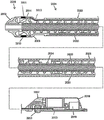
Fig. 1 shows an anatomical view of a segment of an artery cut to show different degrees of atherosclerosis.
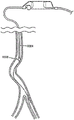
Fig. 2 depicts a diagrammatic anatomical view showing the major arteries of the right leg and typical variations in the diameters of the arteries.
FIG. 3A depicts a perspective view of an illustrative variation of an atherectomy system as described herein.
Figure 3B illustrates an enlarged perspective view of a distal portion of the atherectomy system shown in figure 3A.
Fig. 4A-4D depict an exemplary method by which an atherectomy system may be deployed intravascularly.
Figure 5A depicts an exploded perspective view of a variation of the atherectomy system described herein.
Figure 5B illustrates an assembled cross-sectional side view of the atherectomy system of figure 5A.
Fig. 6A and 6B depict perspective distal and side views, respectively, of variations of the representative cutting elements described herein.
Fig. 6C is a cross-sectional view of the exemplary cutting element taken along line 8C-8C in fig. 6B.
Fig. 6D is a cross-sectional view of the representative cutting element, as shown in fig. 6C, incised into an occlusive material.
FIG. 7 depicts a distal perspective view of a variation of a cutter including a first cutting element and a second cutting element.
Fig. 8A-8C depict various views of a cutting element according to some embodiments.
Fig. 9A-9B illustrate cross-sections of an inner transport member according to some embodiments.
Fig. 10 illustrates removal of an occlusion by an atherectomy device as described herein. Figure 11A depicts a perspective view of a variation of the atherectomy system described herein.
Figure 11B is an enlarged perspective view of a distal portion of the atherectomy system shown in figure 11A.
Figures 11C and 11D depict different ways in which the atherectomy system as shown in figure 11A may be manipulated.
Figure 12A is an exploded perspective view of a variation of the atherectomy system described herein.
Figure 12B illustrates an assembled cross-sectional side view of the atherectomy system shown in figure 12A.
Figure 13A is an exploded perspective view of a portion of the atherectomy system of figures 12A and 12B.
FIG. 13B illustrates an assembled perspective view of the components illustrated in FIG. 13A.
Figures 13C and 13D illustrate the manner in which the atherectomy system shown in figures 12A and 12B may be manipulated.
Fig. 14A-14E and 14F (l) -14F (5) depict the manner in which the atherectomy device (2000) described above with respect to fig. 12A and 12B may be actively and passively steered within a blood vessel.
Figures 15A and 15B depict a variation of the atherectomy device described herein.
Figure 16 illustrates a system for use with the atherectomy devices described herein.
Detailed Description
The present invention provides an atherectomy device for removing an occlusion in a vessel while allowing real-time imaging of the procedure.
In certain embodiments, the devices and methods of the present invention are designed to break up and remove blood clots (e.g., emboli and thrombi), atherosclerosis, plaque, and other occlusive material from a body lumen. A body lumen is generally a diseased body lumen and particularly a coronary artery. Defects in a body lumen may be, for example, re-clotting or intra-stent clotting. However, the devices and methods are also suitable for treating strictures of body lumens and other proliferative and neoplastic disorders in other body lumens (e.g., ureters, bile ducts, respiratory tracts, pancreatic ducts, lymphatic ducts, etc.). Typically, neoplastic cell growth will occur due to tumors surrounding and invading the body lumen. Removal of such material is thus beneficial for maintaining patency of a body lumen. The devices and methods of the present invention may collect lumen resection samples or materials. While the remaining discussion is directed to the extraction, imaging and passage of atherosclerotic or thrombotic occlusive material in coronary arteries, it should be understood that the systems, devices and methods of the present invention may be used to extract and/or pass various occlusions, stenotic or proliferative materials in various body lumens.
The atherectomy device of the invention is particularly well suited for the treatment of atherosclerosis. Atherosclerosis generally affects the middle and large arteries and can occur when fat, cholesterol, and other substances accumulate on the arterial wall and form a fleshy or hard/calcified structure called plaque/lesion. Fig. 1 shows an example of a normal first arterial segment (100) with a native arterial wall (102), a second arterial segment (104) with mild atherosclerosis and incipient plaque (106) formed on the native arterial wall (108), and a third arterial segment (110) with severe atherosclerosis and with advanced plaque (112) formed on the native arterial wall (114). When plaque forms within the natural arterial wall, the artery narrows and becomes less flexible, which can make it more difficult for blood to flow through the artery. In peripheral arteries, plaque is typically not localized, but may extend as much as 10mm or more (in some cases as much as 400mm or more) in length along the axis of the artery.
One of the clinical challenges of atherectomy arises from the natural anatomy of certain peripheral regions (e.g., in the legs) that are indicative of the atherectomy being performed. Accordingly, the anatomy of the leg is described below for certain use prospects of the atherectomy device of the present invention. Fig. 2 shows the anatomy of the major arteries of the leg (200) (the right leg is shown for illustrative purposes). Also shown are the abdominal aorta (202), left iliac artery (204), right iliac artery (206), internal iliac artery (208), external iliac artery (209), common femoral artery (210), superficial femoral artery (212), popliteal artery (214), tibiofibular aorta (216), posterior tibial artery (218), anterior tibial artery (220), and fibular artery (222). The diameter of the peripheral arteries of the leg generally decreases from larger to smaller in the direction of arterial blood flow from above to below the knee.
The abdominal aorta (202) is the largest artery in the body and may range in diameter from 19mm to 25mm (about 0.75 inches to about 1 inch). The abdominal aorta branches or bifurcates sequentially a plurality of times between the proximal and distal regions of the leg. Each subsequent branch or bifurcation may reduce the diameter of the artery in the direction of arterial blood flow from the heart to the feet, and the tortuosity of the path generally increases.
The first branch enters the left common iliac artery (204) and the right common iliac artery (206) at the groin. In the left leg, the left common iliac artery (204) branches into the internal iliac artery (208) and the external iliac artery (209). Near the head of the femur (224), the external iliac artery (209) becomes the common femoral artery (210) or "CPA". The CPA is further connected to the superficial femoral artery (212) or "SPA". The SPA is connected to the popliteal artery (214), which extends behind the flexible region of the knee. Above the knee, SFAs typically have a diameter of about 5mm to 7mm, or about 0.2 inches to 0.25 inches. Traversing distally below the knee (toward the foot), the popliteal artery (214) may further decrease in diameter to about 4mm to 4.5mm (0.157 inch to 0.177 inch), and then further decrease to about 3.5mm (0.137 inch). Further traversing distally, the popliteal artery (214) eventually branches again into the anterior tibial artery (220) and the greater tibiofibular vessel (216), resulting in a further reduction in diameter to about 3.0mm to 2.5mm (0.118 inch to 0.098 inch). Further distally, the tibiofibular great vessel is further subdivided into the posterior tibial artery (218) and the peroneal artery (222), further reducing the diameter to about 2.0mm (0.078 inches). Overall, the diameter of the peripheral arteries of the leg typically varies from about 2mm (below the knee) to about 7mm (above the knee).
Atherectomy devices are typically introduced into the vascular system via the iliac artery by either an ipsilateral (i.e., same side) or contralateral (i.e., opposite side) approach, and are typically advanced through the CFA and into the SFA under fluoroscopic radiographic image guidance. Currently, almost all endovascular atherectomy cases are performed in the SPA, however, in most of these cases, potentially treatable atherosclerosis exists on multiple levels of peripheral arteries above and below the knee. Thus, the devices and methods described herein are helpful in reaching these potential atherectomy sites.
Figures 3A and 3B illustrate the atherectomy system of the present invention according to some embodiments. As shown, the atherectomy system (300) may include an intravascular atherectomy device (302) and a guidewire (304) over which the atherectomy device (302) may be deployed. The guidewire (304) is preferably silicon-coated or uncoated (bare), or otherwise free of a PTFE coating. However, it should be understood that in some variations, the atherectomy systems described herein may include a guidewire with a PTFE coating, or no guidewire at all. In certain embodiments, the guidewire may be a sensing guidewire. For example, the guidewire may be configured to measure functional parameters such as flow, pressure, temperature, and the like. Exemplary functional measurement devices suitable for use in practicing the present invention include Flowire Doppler and ComboWire XT guidewires from Volcano Corporation.
The atherectomy device (302) generally includes an elongated catheter body (306) having a central axis. The catheter body (306) may be sized and configured to be advanced over a guidewire (304) in a blood vessel from an external percutaneous access site. The access plan may be ipsilateral or contralateral and up to the target area. For example, fig. 4A and 4B depict views of a patient's anatomy with a distal portion of an atherectomy device (302) advanced to a target area in the anterior tibial artery (220) using an ipsilateral approach. As shown, the atherectomy device (302) may be introduced into an access site (400) in the right iliac artery (400). Conversely, fig. 4C and 4D depict views of the patient's anatomy with the distal portion of the atherectomy device (302) advanced in a contralateral approach. As shown, the distal portion of the atherectomy device (302) may be advanced through an access site (404) in the left iliac artery (204), across the iliac bifurcation, and up to a target site (in these figures, the target site is shown as a branch of the deep artery (406). to reach the target region along an intravascular path from the access site, the catheter body (306) should have physical and mechanical properties to allow the catheter body (306) to traverse a curved and generally tortuous intravascular path along a guidewire, as will be described in more detail below.
The atherectomy device (302) may also include a handle (308) coupled to a proximal (i.e., closest to the caregiver) end of the catheter body (306). The handle may be sized and configured to be securely held and manipulated by a caregiver outside of the intravascular path. The handle may be maneuvered from outside the intravascular path near the percutaneous access site, which may allow the caregiver to advance the catheter body through the intravascular path, which typically becomes more distorted in the leg as one proceeds toward the distal region of the leg (below the knee and toward the foot). Image guidance (e.g., CT, radiography, live visualization onboard or otherwise provided by the atherectomy device, or other suitable guidance modalities, or combinations thereof) may be used to assist in the advancement or positioning of the atherectomy device (302). The catheter body (306) may be advanced to provide access to a target area where fat, cholesterol and other substances have accumulated on the arterial wall to form a plaque or lesion, which will also be commonly referred to as 11 occlusive substances.
The atherectomy device (302) may further include a cutter assembly (310) at a distal (e.g., furthest away from the handle) end of the catheter body. In general, the cutter assembly may be used to cut and capture occlusive material, and thereby remove the occlusive material from the artery, which may open the artery for blood flow. In some variations, the cutter assembly (310) may include a rotatable cutter (312) housed at least partially within a concentric cutter housing (314). A cutter (312) is rotatable within the housing about a central axis of the catheter body. In the variation shown in fig. 3A and 3B, the cutter housing (314) may be open at its distal-most end, such that the distal-most end of the cutter may protrude distally a distance from the open housing (314). In some of these variations, when the cutter assembly (310) is deployed in a target area where occlusive material is present, there may be no structure or component of the atherectomy that is located in front of (i.e., distal to) the cutter assembly, and thus the first region of the atherectomy device to interact with plaque is the cutter assembly.
The cutter housing (314) may include an imaging assembly (311) located thereon or embedded therein. The imaging assembly (311) may be used to obtain real-time images of the occlusion (atherosclerosis, plaque, thrombus, or emboli) before, during, and after comminution with the cutter (312) to observe the completeness of the procedure or whether more cuts are necessary to completely remove the blockage or restore a suitable lumen opening. Suitable imaging components include opto-acoustic imaging devices, intravascular ultrasound (IVUS), forward looking intravascular ultrasound (FLIVUS), or Optical Coherence Tomography (OCT). Preferably, the imaging assembly (311) is an ultrasound-based imaging assembly. The ultrasound imaging assembly may be a phased array assembly including a plurality of transducer elements. The imaging assembly (311) may be located/embedded on a portion of the housing (314). In certain embodiments, the imaging assembly (311) circumscribes the housing (314). In other embodiments, the imaging assembly (311) is disposed on the catheter body (306) proximal to the housing (314). The imaging assembly, such as imaging assembly (311), is described in more detail below.
Fig. 5A and 5B illustrate exploded views of an atherectomy device (500) suitable for use with the atherectomy systems described herein. As shown, the atherectomy device (500) may include a handle (502), a catheter body (504), and a cutter assembly (506), as described above with respect to fig. 3A and 3B. As shown in fig. 5A and 5B, the cutter assembly (506) may include a ferrule (508), a cutter housing (510), and a cutter including a first cutting element (512) and a second cutting element (514). It should be understood that the atherectomy device (500) may include any suitable cutter assembly, such as those described in more detail below. The housing 510 may include an imaging component 511. The imaging assembly 510 is connected to one or more signal lines (513) which are in turn connected to a signal processing device. The signal line (513) transmits energy to the imaging component 511 to emit an imaging signal (e.g., an ultrasound or optical signal), and transmits a post signal (post echo) received from the imaging component to the signal processing device and the imaging console. The signal wire (513) may extend along the sides of the inner surface of the catheter body (504) to a signal processing device, or the signal wire (513) may be incorporated into the catheter body (504). In certain embodiments, the catheter body (504) may define a separate lumen through which the signal wire (513) may be routed.
The atherectomy device (500) may include a motor (516), which in the embodiment shown in fig. 5A and 5B may be housed within a housing portion (518) of the handle (502). The motor is desirably battery powered, by using replaceable batteries, by using rechargeable batteries, or a combination of both. The motor controller is expected to provide a consistent power supply for all operating conditions, including no-load to excessive torque and stall conditions. A control switch (520) (e.g., a slide switch, button, and/or potentiometer) may be provided to include an off/on function, and in some cases, one or more of various other control functions, such as ramping up and/or down, and/or variable speed. In some variations, the motor may operate at about 12,000RPM at a nominal voltage of 6 volts. The operating parameters may be changed by adjusting the transmission ratio.
As shown in fig. 5A and 5B, a torque shaft (522) may connect the motor (502) to the cutter. Specifically, the motor (502) may rotate the torque shaft (522), which in turn may rotate the cutter within the cutter housing (510) about the central axis of the catheter body. Rotation of the cutter assembly (506) may cause the first cutting element (512) and/or the second cutting element (514) to cut the occlusive material and deliver the occlusive material into the cutter housing (510) (a process also referred to as "debulking"). Preferably, cutter assembly (506) captures the severed occlusive material from the blood without the use of any vacuum suction (although it should be understood that in some variations, vacuum suction may assist in the delivery of the severed occlusive material).
Additionally, the atherectomy device (500) may further include an internal conveyor (524) on the torque shaft (522). As occlusive material is delivered by the cutter into the cutter housing (510), a carrier (524) may further deliver the cut occlusive material rearward (proximally) along the catheter body for discharge out of the patient's body. As mentioned above, this transfer may occur without the use of vacuum suction assistance. Mechanical delivery may supplement distal capture. Because it does not require the assistance of vacuum aspiration, mechanical delivery can minimize the risk of arterial collapse around the cutter and the associated risk of perforation. In addition, such delivery may maximize the removal of tissue and blood components that have been destroyed by contact with the cutter assembly.
In further embodiments, a catheter body (504), a housing (510) coupled to the catheter body, and an imaging assembly (511) disposed on the housing (510) are configured to rotate. For example, these components may be coupled to a rotating drive shaft to effect rotation. Rotary drive shafts configured to rotate a catheter body and an imaging element are known in the art.
The rotation of these components can serve several purposes. For example, rotation may be used as a means to further break down the plugs. In another example, the rotation may assist in moving broken plug particles into the catheter body (504) for removal. Additionally, rotation can be used to assist in imaging the luminal surface of the vessel wall (e.g., the luminal surface within an intramural space). For example, imaging elements (such as optical coherence tomography and ultrasound imaging elements) capture cross-sectional imaging data obtained during rotation of the imaging element. In some embodiments, rotation of the catheter body (504) and associated elements opposes rotation of the torque shaft (522). This counter-rotation may increase the effectiveness of the internal conveyor (524) in removing broken particles.
The individual components of the systems shown in fig. 3A, 3B, 5A, and 5B are discussed in more detail below.
A. Catheter body
1. Size of
Indeed, the outer diameter of any segment of the catheter body (including the cutter assembly carried thereby) may be determined at least in part by the intravascular path and the anatomy of the intended target area. In particular, it may be desirable to maximize the cutting effectiveness of the cutter assembly by maximizing the cutter diameter while minimizing the likelihood of vessel puncture or trauma. In addition, the outer diameter of the catheter body/cutter assembly may also be determined, at least in part, by the diameter of a selected guide sheath or introducer that may be placed at the access site to allow introduction of the atherectomy device into the vascular system. It may be desirable to select an introducer sheath or introducer that is sized to minimize pain, trauma and blood loss during use, and to facilitate rapid closure of the access incision after removal, thereby reducing the incidence of interventional complications.
As mentioned previously, the diameter of the peripheral arteries of the leg typically varies from a relatively small diameter (2.0mm) in the area below the knee to a relatively large diameter (7.0mm) in the area above the knee. To gain percutaneous access to the peripheral artery, clinicians typically use sheaths ranging in size from 5F (diagnostic) to 7F (interventional).
For example, from a clinical standpoint, given that a 7French introducer sheath would be the largest size selected for access to the larger vessels above the knee (4mm to 7mm), and allowing for reasonable clearance tolerances between the catheter body/cutter assembly and the introducer sheath, the outer diameter of the catheter body for introduction through such an introducer sheath may be selected to be approximately equal to or less than about 2.4mm in some cases.
From a clinical standpoint, the outer diameter of the catheter body for introduction through such an introducer sheath may be selected to be approximately equal to or less than about 1.8mm in some cases, assuming that a 5F introducer sheath would be the largest dimension selected for access to the smaller vessels below the knee (2.5mm to 3mm), and allowing for reasonable clearance tolerances between the catheter body/cutter assembly and the introducer sheath. From a clinical standpoint, given that a medium 6French introducer sheath would be the largest size selected for accessing the medium blood vessels near the knee (3mm to 4mm), and allowing for reasonable clearance tolerances between the catheter body/cutter assembly and the introducer sheath, the outer diameter of the catheter body for introduction through such an introducer sheath may be selected to be approximately equal to or less than about 2.2mm in some cases.
It may be desirable to maximize the outer diameter of the cutter assembly to maximize the total cutting area of the atherectomy assembly. When the cutter assembly of the atherectomy device is the distal-most component of the device, the cutter assembly may be routed by cutting through the occlusive material. However, functional and clinical benefits may result when the outer diameter of the catheter body is not maximized to match the outer diameter of the cutter assembly, as with the catheter body. Reducing the diameter of the catheter body relative to the cutter assembly may minimize frictional contact between the catheter body and the vessel wall. This may reduce the force required to advance the catheter body through the vascular system and occlusive material, and may help avoid the catheter body from dragging against or sticking to tissue structures in the blood vessel, or otherwise impeding the advancement of the cutter assembly through the occlusive material.
For example, it may be desirable for the outer diameter of the catheter body proximal to the cutter assembly to be sized smaller than the outer diameter of the cutter assembly. In other instances, it may be desirable for the outer diameter of the catheter body proximal to the cutter assembly to be sized equal to or less than the outer diameter of the cutter assembly. For example, in variations of the atherectomy device (500) described above with respect to fig. 5A and 5B, the catheter body (504) may have an outer diameter that is smaller than the outer diameter of the cutter assembly (506).
The reduced diameter of the catheter body may also allow for the injection of radiographic contrast media in the sheath, around the catheter body. For example, an atherectomy device for introduction through a 7F introducer system may have a cutter assembly with a diameter of 2.4mm and a catheter body with a diameter of 2.2 mm. In other variations, an atherectomy device for introduction through a 5F or 6F introducer system may have a cutter assembly with a diameter of 1.8mm and a catheter body with a diameter of 1.6mm, or a cutter assembly with a diameter of 2.2mm and a catheter body with a diameter of 1.6 mm.
2. Catheter characteristics
In addition to anatomical and clinical considerations that may be used in selecting the outer diameter of the catheter body, the catheter body desirably also has certain physical and mechanical properties, such as those described immediately below, that may enhance the function of the catheter body to support and guide the cutter assembly through intravascular pathways and occlusive material.
(i) Column stiffness (push-type)
One potentially desirable characteristic of the catheter body includes column stiffness. Column stiffness, in inches/ft-lbs, is the ability of the catheter body to withstand axial loads or pressures while resisting bending. Column stiffness may be measured and characterized in a conventional manner, and may be referred to herein as "pushability. Generally, higher column stiffness is desirable and may allow the catheter body to transfer higher axial forces (compression) applied at the handle to the cutter assembly without buckling.
Accordingly, it may be desirable for the catheter body to have a column stiffness sufficient to push the cutter assembly over the guidewire without buckling. A column stiffness of 0.050 inches/pound or greater is desirable for the catheter bodies described herein.
(ii) Tensile stiffness (traction)
Another potentially desirable characteristic of the catheter body includes tensile stiffness. Tensile stiffness, in inches/foot-pound, is the ability of the catheter body to withstand tension when stretched or pulled before the cross-section begins to significantly shrink (referred to as "necking"). Tensile stiffness may be measured and characterized in a conventional manner, and may be referred to herein as "traction. In general, a high tensile stiffness is desirable and may allow the catheter body to be pulled proximally along an intravascular path without necking (e.g., to withdraw the cutter assembly). A tensile stiffness of 0.050 inches/pound or greater is desirable for the catheter bodies described herein.
(iii) Torsional rigidity (torsion)
Another potentially desirable characteristic of the catheter body includes torsional stiffness.
Torsional stiffness, in degrees/ounce-inch, is the ability of the catheter body to transmit rotational loads (torque) without under-twisting, over-twisting, and/or deformation. Torsional stiffness can be measured and characterized in a conventional manner, and may be referred to herein as "torqueability". Torsional stiffness can control the ability of the catheter body to transfer a given amount of rotation imparted at its proximal end (i.e., the handle) to achieve a comparable amount of rotation at its distal end (i.e., the cutter assembly). A higher torsional stiffness is desirable to better allow rotational transmission along the atherectomy device (i.e., around the guidewire) without twisting or deformation. For the catheter bodies described herein, a torsional stiffness that achieves a 1:1 relationship between the rotation imparted at the proximal end and the rotation observed at the distal end is desirable.
(iv) Bending stiffness (circulation)
Another potentially desirable characteristic of the catheter body includes bending stiffness.
Bending stiffness, in units of bend radius (expressed in inches), is the ability of the catheter shaft to bend in response to an applied bending force without breaking or deforming (i.e., without overbending). Flexural rigidity is a general material property that can be measured and characterized in a conventional manner, and may be referred to herein as "tracking".
Generally, a lower bending stiffness is desirable to allow navigation of the catheter body over the guidewire around tight bends in the vascular system. For the catheter bodies described herein, it is desirable to have a target bending stiffness of 0.5 inches (bend radius) or greater at the mid-length of the catheter body. If the catheter body includes an active deflection member at its distal end (as described in more detail later), a target bending stiffness of 1.0 "(bend radius) at the deflectable distal end is desired for the catheter bodies described herein. The prescribed minimum bend radius also allows the catheter body to be rolled without over-bending to facilitate packaging.
Conventionally, tracking is considered to be inversely related to pushability/tractability and torqueability. That is, greater pushability, tractability, and/or torqueability in the catheter body may result in reduced tracking of the catheter body. However, the catheter bodies described herein may balance pushability, tractability, torqueability, and trackability of a given catheter body. The result may be that the catheter body is traversable, and also possesses the column strength, tensile strength, and torsional stiffness necessary to be sufficiently pushable, tractable, and twistable, allowing navigation and advancement of the cutter assembly.
The tracking of a given catheter body (in terms of its ability to reliably navigate over the guidewire) is primarily affected by the physical and mechanical properties of the catheter body at its distal end. Pushability, tractability and torquability are primarily affected by the physical and mechanical properties of the catheter body proximal to its distal end. That is, the overall configuration of different regions of the catheter body imparts characteristics to the overall length of the catheter body, which may allow optimization of the overall pushability, tractability, torqueability, and trackability of the catheter body.
3. Variations of catheter body
Generally, the column stiffness, tensile stiffness, torsional stiffness, and bending stiffness of the catheter body may be determined at least in part by the material from which it is constructed, the dimensions of the catheter body (e.g., inner diameter, outer diameter, wall thickness, etc.), and other structural features such as patterns. The catheter body may be fabricated from a metal tube (e.g., type 304 stainless steel tube, etc.). The size of the tube may depend, at least in part, on the intended use of the atherectomy device. For example, in some variations, the outer diameter of the tube may desirably be about 2.2mm, while in other variations, the outer diameter of the tube may be about 1.6 mm. Additionally or alternatively, the wall thickness of the tube may preferably be about 0.288 mm. Additionally or alternatively, the overall length of the tube may preferably be about 1437mm (about 56.56 inches).
A metal tube having some or all of the dimensions described immediately above may provide a high degree of pushability, tractability and torqueability, with the baseline bending stiffness limiting the tracking of the catheter body given its length.
Thus, in some variations, the bending stiffness of the metal tube may be adjusted progressively along the length of the catheter body by forming multiple cutting pattern zones along at least a portion of the length of the catheter body. The cutting pattern may be formed in any suitable manner (e.g., via laser cutting), and the zones may impart a desired bending stiffness distribution over the length of the catheter body. For example, the cut pattern regions may be used to progressively reduce the bending stiffness in a stepwise manner from the proximal end to the distal end to provide a minimum bending stiffness that facilitates tracking at the distal end (when tracking is more desirable). The step-wise manner of reducing bending stiffness may be configured in a manner that helps maintain overall pushability, tractability, and torqueability. In certain embodiments, one or more regions of the catheter body comprise a helical cut pattern, or a bricklayed cut pattern.
The catheter body with any cutting pattern may be lined or sheathed with a polymeric material and may also be treated to impart hydrophilic, hydrophobic or drug binding (heparin, antimicrobial) properties.
4. Catheter body rotation
As discussed above, the catheter body 504 (as well as the housing and imaging assembly) may be configured for rotation. In certain embodiments, the catheter body 504 is coupled to a rotary drive shaft that drives rotation of the catheter body 504. In other variations, the catheter body may be coupled to a post on the handle that is sized and configured to rotate in response to rotation of the control knob. For example, the atherectomy device (500) described above with respect to fig. 5A and 5B may include a rotation knob (526). Rotation of the knob may apply torque to the catheter body to selectively rotate the cutter assembly. The indexing mechanism may be provided to provide step-wise control with tactile and/or audible feedback so that the caregiver maintains knowledge of the rotational position of the cutter assembly without taking his eyes off of radiographic images or otherwise provided live images.
Torque may also be applied to the catheter body by rotating the handle itself.
The selective rotation of the cutter assembly can thus be finely controlled by a combination of manipulation of the control knob and twisting of the handle.
B. Cutter assembly
As mentioned above, the atherectomy device may include a cutter assembly. The cutter assembly may include a cuff, a cutter housing, and a cutter including at least one cutter element. In variations where the cutter assembly includes a cuff, the cutter assembly may be connected to the distal end of the catheter body by the cuff. In certain embodiments, the cutter assembly further comprises an imaging assembly associated with the cutter housing.
1. Cutter shell
As previously mentioned, the cutter assembly may include a housing in which the cutter rotates. It may be desirable to maximize the outer diameter of the cutter assembly (and the cutter housing with the cutter assembly) to maximize the cutting area that may be cut by the cutter assembly. The size of the cutter assembly may be limited according to the intended intravascular path and target area for treatment to help reduce the likelihood that the cutter assembly will cut or otherwise damage the vessel wall.
In some of the variations described herein, a cutter assembly sized for introduction through a 7French introducer sheath may have an outer diameter of about 2.4mm (which in some variations may be larger than the outer diameter of the accompanying catheter body, as described in more detail above). Cutter assemblies having such outer diameters may be used, for example, to access larger blood vessels above the knee (e.g., blood vessels between about 4mm and about 7 mm). In other variations described herein, a cutter assembly sized for introduction through a 5 or 6French introducer sheath may have an outer diameter of about 1.8mm to about 2.2mm (which in some variations may be larger than the outer diameter of an accompanying catheter body, as described in more detail above). Cutter assemblies having such outer diameters may be used, for example, to access smaller vessels at or below the knee (e.g., vessels between about 2.5mm and about 4 mm).
The housing may or may not be dynamic (i.e., capable of rotating relative to the catheter body). In variations where the housing is dynamic, the housing may be configured to rotate at the same speed or at a different speed than the cutter elements. In addition, the cutter housing may be dynamically driven to rotate relative to the cutter in the same direction or in opposite directions.
The housing may include one or more imaging assemblies. The imaging assembly may be disposed on or embedded within the housing. The imaging assembly may cover a portion of the housing, and preferably the imaging assembly circumscribes the housing. The imaging assembly is connected to one or more signal lines extending along the length of the atherectomy device.
The leading edge of the cutter housing (which defines the perimeter of the distal opening through which the cutter protrudes) is desirably rounded and absent a sharp distal edge. In these variations, the rounded distal housing may reduce the likelihood of the peripheral edge of the housing hanging on the wall of the introducer sheath as it is introduced through the introducer sheath.
In addition, the rounded distal edge may also tend to sweep through tissue without catching or catching on the tissue, which may minimize the resistance felt by the atherectomy device during advancement. It should be understood that in some variations, the cutter housing may have a sharp or beveled distal edge. In some of these variations, the cutter housing may have an internal bevel. In other variations, the cutter housing may have an outer bevel.
In some variations, the outer diameter of the cutter may be less than the inner diameter of the cutter housing to create the desired cutting gap therebetween. Larger gaps may produce larger cutting volumes, but too large a gap may allow tissue to bypass the cutter and enter the cutter housing. Representative dimensions will be described in more detail later. In other variations, the outer diameter of a portion of the cutter may be greater than or equal to the diameter of the cutter housing. In these variations, the cutter may cut larger diameter tissue, which may reduce the likelihood that the cutter housing will rub against the tissue while cutting during advancement, thereby facilitating advancement of the device.
2. Torque shaft
The cutter is coupled by and rotatable by a torque shaft. The torque shaft may in turn be driven by a motor in the handle. The torque shaft may be made of any suitable material, preferably one or more materials that may conform to the pushability, tractability, torqueability and trackability of the catheter body, as described above. For example, the torque shaft may include a metal braid and/or one or more metal coils, and one or more portions of the torque shaft embedded in a polymer (e.g., PEBAX, polyurethane, polyethylene, fluoropolymer, parylene, polyimide, PEEK, and/or PET). In some variations, the torque shaft may be made of a rigid material, such as plastic, that exhibits flexibility by including helical projections or grooves.
In some variations (such as the torque shafts depicted above for fig. 3A, 3B, 5A, and 5B), the torque shaft may comprise a flexible wire loop wrapped around a central lumen.
The central lumen may be sized to accommodate passage of a guidewire therethrough. The flexible wire coil may preferably be wound in the same direction as the predetermined rotational direction of the torque shaft, which may cause the coil to open when encountering torsional resistance to rotation (as opposed to compression which may cause the torque shaft to lock onto a guide wire positioned in the central lumen).
In general, the torque shaft may be coupled to a cutter of the cutter assembly at or near a distal end of the torque shaft and may be attached to the motor (e.g., via a gear arrangement) at or near a proximal end of the torque shaft. In some variations (such as the atherectomy devices described in fig. 3A, 3B, 5A, and 5B), the cutter assembly may include a central lumen that may be in communication with the central lumen/guidewire lumen of the torque shaft.
3. Geometry of cutting elements
As mentioned above, in some variations, the cutter of the cutter assembly may include multiple cutting elements. For example, in variations of the atherectomy device (500) described above with respect to fig. 5A and 5B, the cutter assembly (506) may comprise a cutter having a first cutting element (512) and a second cutting element (514). As shown, the first cutting element (512) may be positioned distal to the second cutting element (514). The first cutting element (512) may include one or more cutting edges (528) that may at least partially protrude beyond the distal end of the cutter housing (510). In some variations, at least a portion of the first cutting element (512) may have a diameter greater than or equal to a diameter of the cutter housing (510). The second cutting element (514) may be at least partially housed within the cutter housing (510) and may include one or more cutting edges (530). As shown in fig. 5B, the cutting edge (530) of the second cutting element (514) may be completely enclosed within the cutter housing (510). Generally, the first cutting element (512) and the second cutting element (514) may be physically coupled together (e.g., by an adhesive or welding) for common rotation.
The torque shaft may be coupled to a journal (532) in the second cutting element. When the first cutting element (512) and the second cutting element (514) are physically coupled together, the torque shaft may collectively rotate both the first cutting element and the second cutting element. A proximal flange (534) on the second cutting element (514) may be seated within a raised proximal groove (536) in the cutter housing (510). The embossed proximal groove (536) may serve as an axial retainer for the first cutting element (512) and the second cutting element (514) within the cutter housing.
(i) First cutting element
Fig. 6A-6D depict exemplary variations of a first cutting element (800) suitable for use with the cutter assemblies described herein. In some variations, the first cutting element (800) may be machined from a hard metallic material (e.g., 440C stainless steel) and may have a generally hemispherical configuration including at least one helical flute (802) (shown as right-handed in the figures, but it is understood that the at least one helical flute (802) may have a left-handed configuration). Although shown in fig. 6A-6D as having two helical flutes (802), it should be understood that the first cutting element (800) may include any suitable number of helical flutes (802) (e.g., one, two, three, four, or more helical flutes). Each cutting slot may form a cutting blade (803) having a cutting edge (804).
The first cutting element may be machined to form the structure of a helical flute (802) within a desired hemispherical geometry. When supported in an extended, distally projecting relationship relative to the cutter housing (e.g., by virtue of the connection with the second cutting element, as described in more detail above), the hemispherical, slotted geometry may be sized and configured to optimize the ability of the one or more cutting blades to cut through and capture occlusive material while minimizing the risk of the one or more cutting blades catching or digging into tissue, wrapping around tissue, and otherwise stalling and overloading the motor.
The geometry of each flute may be purposely shaped for the purposes mentioned above, and the flute geometry may be characterized with reference to a combination of angles (or a range of angles), including a rake angle, a relief angle, a flute angle, and a helix angle. Additionally, although shown in fig. 6A-6D as having a semi-spherical outer profile, it should be understood that the anterior cutting element may be any outer profile, such as an oval outer profile.
(a) Front angle
For each flute, a rake angle (806) (best shown in fig. 6C) may be defined as the angle measured between (i) a radius (808) drawn from the axis of rotation of the cutting blade (810) to the radially outermost edge (804) of the blade (803) and (ii) a tangent line (810) drawn from the inner face of that blade (803). The rake angle may describe the angle of the cutting edge (804) relative to the material to be cut.
In some variations, each flute of the first cutting element may possess a positive rake angle (i.e., the inner face of the cutting blade is inclined inwardly or rearwardly from the cutting edge). The positive rake angle of each flute is preferably large, and in some cases may be greater than about 20 degrees. In some of these variations, the rake angle is preferably greater than about 40 degrees. In some of these variations, the rake angle may be between about 60 and 80 degrees (referred to herein as a "high" rake angle). In some variations, the rake angle may be between 65 degrees and 75 degrees. In some variations, the rake angle may be about 70 degrees.
Generally, devices with a positive high anterior angle may be well suited for cutting occlusive materials with less calcium, which may have fibrous, fleshy, and/or rubbery consistency. The rubbery consistency can cause conventional cutters to deflect from these substances, causing the conventional device to lose tracking, but the high rake angle helps the cutter to cut into this tissue while minimizing cutter deflection. Machining techniques for conventional cutters generally fail to produce positive high rake cutters, and these cutters generally have a low rake angle (less than about 15 degrees). In addition, a larger rake angle may reduce the structural integrity of the cutter, which may chip or break during use of the cutter. However, the cutters described herein may allow for the benefits of high rake cutting to be achieved while reducing the risk of cutter failure.
The rake angle of the cutter may be modified depending on the nature of the tissue to be cut. For example, cutter assemblies for cutting hard, calcified occlusive materials with higher calcium content may be configured to have a negative rake angle (i.e., the inner face of the cutting blade may be inclined outward or forward of the cutting edge), which may be well suited to grind or pulverize hardened occlusive materials. It should be understood that a given cutting element may be machined to include cutting blades having both positive and negative rake angles or otherwise include a combination of both cutting and abrading surfaces. For example, in some variations, a cutter may include a first cutting element having a plurality of helical flutes, wherein at least one flute has a cutting edge with a positive rake angle and at least one flute has a cutting edge with a negative rake angle. In some of these variations, a helical flute having a cutting edge with a positive rake angle may have a positive rake angle greater than about 20 degrees (e.g., greater than about 40 degrees or about 70 +/10 degrees)
In the variation of the first cutting element (800) shown in fig. 6A-6D, the formation of slots having a large positive rake angle (e.g., 70 ° ± 10 °) may result in cutting blades having enlarged concave inner faces. The enlarged concave interior face may define a slot or scoop-shaped blade effective to cut through occlusive material (812), as shown in fig. 6D. The large positive (high) rake angle of the cutting blade and the resulting enlarged concave inner face can reduce the cutting force and power requirements for the first cutting element (800), and can remove a large volume of occlusive material with each pass of the cutting blade.
(b) Relief angle
For each slot, the relief angle (814) may be defined as the angle measured between (i) a tangent line (816) drawn from the radius (808) from the most distal radial edge (804) of the cutting blade (803) and (ii) a tangent line (818) drawn along the outside of the blade (803). The relief angle generally spans the gap between the cutting edge (804) and the surface of the occlusive material (812) to be cut (as shown in fig. 6D). In general, a smaller relief angle may form a more tangential interface with the tissue surface during cutting, which may reduce the likelihood that the cutting edge may snag or otherwise hang on the tissue during cutting. Greater relief angles may provide a more aggressive cut.
Generally, the relief angle is preferably a small angle less than or equal to about 10 ° (e.g., between about 0 ° and about 10 °). In some of these variations, the relief angle may be about 0 °. In some variations, it may be preferred to have a rake angle of about 70 degrees and a relief angle of about 0 degrees. In other variations, the helical groove may have a rake angle of about 60 degrees and a relief angle of about 10 degrees. The formation of a groove with a small relief angle may create a cutting edge (804) that may make aggressive contact with the occlusive material (812), as shown in fig. 6D. Along with a large positive (high) rake angle, a small rake angle may result in efficient cutting and capture of occlusive material at the distal end of the cutter assembly, minimizing debris and emboli.
(c) Groove corner
For each slot, a slot angle (824) may be defined in terms of a relationship to the rake and relief angles as follows:
the groove angle is 90 ° - (front angle) - (rear angle).
The magnitude of the flute angle is an indication of how thick and sharp the cutting edge is. Provided that in a preferred embodiment the rake angle may be in the range between about 60 ° and 80 °; the back angle may be in a range between about 0 ° and 10 °, and the groove angle may be in a range between about 0 ° and about 30 °. Maximizing the rake angle and minimizing the relief angle to achieve efficient cutting conditions can result in cutter geometries with reduced flute angles. It may therefore be desirable for the first cutting element to be machined from a hard metal material to include a cutting edge that is as sharp as possible. In some variations, it may also be desirable to coat the cutting blade with a biocompatible, highly lubricious material having a low coefficient of friction (preferably no greater than 0.5) to help maintain the sharpness of the cutting blade during use. In these variations, a coating material such as titanium nitride or diamond-like carbon (DLC) may be used.
(d) Helix angle
In the variation of the first cutting element (800) shown in fig. 6A-6D, each flute (802) of the first cutting element (800) may comprise a helical cut. The helix angle (826) may be defined as the angle between (i) the axis of rotation (828) of the cutting blade (803) and (ii) a tangent line (830) drawn along the inner face of the cutting blade (803). The magnitude of the helix angle is indicative of the ability of the cutting blade to transport the cut occlusive material proximally along the cutting blade into the housing.
In some variations, each flute (802) of the first cutting element (800) may have a helix angle (802) of between about 30 ° and 60 °. A helix angle below 30 ° may increase the likelihood that the first cutting element (800) will be overloaded with occlusive material and stall, while a helix angle above 60 ° may decrease the cutting efficiency of the first cutting element (800).
Fig. 8A to 8C show a first cutting element according to further embodiments. As shown in fig. 8A-8C, the cutting element may include one or more blades 1110, one or more blunt crushing elements 1008, or both. One or more blades 1110 may be designed with the angular geometry discussed above. Blade 1110 is designed to cut through an occlusion as the cutting element is rotated. The crushing element 1008 is designed to transmit crushing blows to the occlusion. That is, the crushing element 1008 is designed to deliver a blow or sudden impact to the occlusion, thereby further breaking the occlusion except for the blade 1110 alone. In particular, the crushing elements 1008 are useful in breaking through fibrous plaque and highly organized thrombi. The crushing elements 1008 are preferably blunt and generally rectangular in shape. In certain embodiments, the crushing elements 1008 form a zero rake angle or a negative rake angle (as opposed to a positive rake angle of the blades 1110). The negative rake angle can range from at least 1 degree, 5 degrees, 10 degrees, 15 degrees, 20 degrees, 25 degrees, 30 degrees, or more. However, the crushing elements 1008 may comprise other shapes, such as spherical, triangular, cylindrical, hexagonal, and the like. Although the body of the crushing element is generally blunt, the edges of the crushing element may be sharp to also assist in cutting through the occlusion. One or more crushing elements 1008 may be disposed between blades 1110 (as shown in fig. 8A-8C). In certain embodiments, the crushing element 1008 is formed from a different material than the remainder of the cutting element. The crushing elements 1008 are desirably formed of a metal carbide such as titanium carbide.
(ii) Second cutting element
As mentioned above, the cutter assembly may include a second cutting element. For example, in the variation of the atherectomy device (500) shown in fig. 5A and 5B, the cutter assembly (506) may include a second cutting element (514). In variations that include a second cutting element, the second cutting element may be machined from a hard metal material (e.g., 17-4 stainless steel) to include a spiral cut groove. The cutting flutes may be configured to have the same rake, relief, flute and helix angles as the flutes of the first cutting element. In some variations, the above-described geometries of the first cutting element and the second cutting element may be the same, except that the second cutting element has more slots than the first cutting element. In some of these variations, the second cutting element may have double the number of flutes of the first cutting element; that is, four slots are shown.
In some variations, the second cutting element is machined to include a hollow rod that fits within a central journal of the first cutting element. For example, in the variation of the atherectomy device shown in fig. 5A and 5B, the second cutting element (514) may comprise a rod (538) around which the first cutting element (512) may be placed. For example, fig. 9 illustrates a perspective view of a cutter assembly (506) in which a first cutting element (512) and a second cutting element (514) may be coupled together in rotational alignment (e.g., by adhesive or welding). In the aligned state, the two opposing cutting slots (540) of the second cutting element (514) are rotationally alignable with the two opposing cutting slots (542) of the first cutting element (512). Their geometries may be matched during machining and may be used to cut occlusive material with the first cutting element and deliver the occlusive material proximally into the housing, and further deliver the occlusive material more proximally into contact with the additional cutting blade of the second cutting element.
(iii) Two stage cutting action
The cutter assembly (506) shown in fig. 7 may provide a two-stage cutting action.
Generally, a first cutting element (512) may cut occlusive material and deliver the material to a second cutting element (514). The second cutting element (514) may further cut or pulverize the occlusive material into smaller particles. During both cutting actions, occlusive material may be continuously captured within the housing and delivered proximally away from the intravascular target site. The helical cutting surface formed by the slots can cut occlusive material in the vessel as the first and second cutting elements rotate, and the occlusive material can be delivered from the vessel into the housing by the action of the helical slot, and can do so without any vacuum suction assistance.
C. Mechanical removal of occlusive material
As mentioned above, in some variations of the atherectomy devices described herein, the atherectomy device includes an internal delivery member. For example, a variation of the atherectomy device (500) shown in fig. 5A and 5B may include an internal transporter (524). In variations that include an inner delivery member, the inner delivery member may include a wire helically wound about the torque shaft in a common direction with the helical cutting surface of the cutter assembly. The cross-section of the inner conveyor member may be substantially circular or rectangular in shape. Fig. 9A shows an inner transport member having a circular cross-section and fig. 9B shows an inner transport member having a rectangular cross-section. The rectangular cross-section may increase the amount of contact between the conveyor and the inner surface of the catheter body, thereby increasing the ability of the conveying member to move the obstruction particles along the length of the catheter. When the cutter assembly cuts and captures occlusive material (e.g., when the helical flutes of the first and/or second cutting elements deliver the cut and captured occlusive material to the delivery member), the delivery member may be co-rotated with the torque shaft to deliver the cut and captured occlusive material it receives from the cutter assembly further back (proximally) along the catheter body into the handle. For example, fig. 10 shows a variation of the atherectomy device (500) described above with respect to fig. 5A and 5B, with occlusive material (1700) delivered and delivered proximally through the device.
Occlusive material carried back into the handle by the delivery element may be delivered into a discharge channel within the handle. A delivery pusher in communication with the discharge channel may be coupled to the torque shaft for common rotation therewith and may be used to pump the incised, captured and delivered occlusive material into the discharge channel. The drain channel may include an external coupler (e.g., a luer connector) to couple the drain channel to an external waste container. The cut and captured occlusive material can be delivered into a waste container and can do so without the need for vacuum suction. For example, as shown in fig. 10, the atherectomy device (500) may include a delivery pusher (544), a discharge channel (546), and an external coupling (548) that may be connected to an external waste container (1702), as just described.
In some instances, it may be desirable to deliver saline or another biocompatible fluid along the catheter body for mixing with occlusive material within the cutter assembly. Mixing the fluid with the occlusive material may form a slurry, which may reduce the viscosity of the material cut, captured and delivered from the blood vessel by the atherectomy device. This may reduce the load placed on the cutter assembly and facilitate the transfer of material to the waste container. As shown in fig. 10, the atherectomy device (500) may deliver fluid (1704) from the distal end of the apparatus. In some variations, the fluid (1704) may be delivered through an internal/guidewire lumen within the torque shaft (522).
Deflectable atherectomy systems and devices
In some variations, the atherectomy systems described herein may include an atherectomy device configured to be selectively dynamically deflected at a distal end thereof (e.g., near the cutter assembly). For example, fig. 11A-11D illustrate one variation of an atherectomy device (1800) including a handle (1802), a catheter body (1804), and a cutter assembly (1806). These elements may include any of the previously described features. As will be described in more detail, the catheter body (1804) may be configured to dynamically deflect at its distal end (carrying the position of the cutter assembly (1806)) relative to the central axis of the proximal catheter body (1804), as shown in fig. 11C. The deflection may occur without axial advancement of the atherectomy device. Additionally, the atherectomy device (1800) may be configured to rotate the distal end of the device while deflecting about the central axis of the proximal catheter body (1804) to sweep the cutter assembly (1806) along an arc (1808) about the central axis, as shown in fig. 11D. The sweeping capability of the atherectomy device (1800) may allow the cutter assembly to cut occlusive material in a region larger than the outer diameter of the cutter assembly, as will be described in more detail below.
The atherectomy device (1800) may be used in an atherectomy system comprising a guidewire (1810) and may be introduced into a blood vessel from an external percutaneous access site, as previously described with respect to fig. 4A-4D. The handle (1802) may be sized in the manner previously described and configured to be securely held and manipulated by a caregiver outside the intravascular path to advance the catheter along the vessel. Image guidance (e.g., CT, radiographic, or guidance mechanisms, or combinations thereof) may be used to assist the caregiver in maneuvering.
Fig. 11A and 11B depict a variation of an atherectomy device (2000) configured for use with the atherectomy systems described herein. As shown, the atherectomy device (2000) may include a handle (2002), a catheter assembly (2004), and a cutter assembly (2006). As shown, the cutter assembly (2006) may include a ferrule (2008), a cutter housing (2010), a first cutting element (2012), and a second cutting element (2014). The cutting assembly may have any element or combination of elements as described in more detail above. For example, the cutter housing (2010), the first cutting element (2012), and the second cutting element (2014) may have any of the elements and dimensions previously described. In some variations, the first cutting element and the second cutting element may each include one or more helical cutting flutes having a rake angle between about 60 degrees and 80 degrees, a rake angle less than or equal to 10 degrees (in some of these variations, about 0 degrees), a flute angle between about 30 degrees and about 0 degrees, and a helix angle between about 30 and about 60 degrees.
As also shown in fig. 12A and 12B, the atherectomy device (2000) may further include a drive motor (2016), which in some variations may be housed in a housing (2018) of the handle (2002). Also shown is a torque shaft (2020) that may be coupled to the motor (2016) at a proximal end of the torque shaft (2020) through a gear arrangement and to the second cutting element (2014) at a distal end of the torque shaft (2020). The torque shaft rotates the first cutting element (2012) and the second cutting element (2014) relative to the cutting assembly, as described in more detail above. As the cutter rotates, it can cut occlusive material and deliver it into the cutter housing (2010), and can do so without using any vacuum suction.
The cutter housing (2010) may include an imaging assembly (2011) disposed thereon or embedded therein. An imaging assembly (2011) may be used to obtain real-time images of the occlusion (atherosclerosis, plaque, thrombus, or emboli) before, during, and after comminution with a cutter (2012) to observe the completeness of the procedure or whether more cuts are needed to completely remove the blockage or restore a suitable lumen opening. Suitable imaging components include opto-acoustic imaging devices, intravascular ultrasound (IVUS), forward looking intravascular ultrasound (FLIVUS), or Optical Coherence Tomography (OCT). Preferably, the imaging assembly (2011) is an ultrasound-based imaging assembly. The ultrasound imaging assembly may be a phased array assembly including a plurality of transducer elements. The imaging assembly (2011) may be disposed/embedded on a portion of the housing (2010). In certain embodiments, the imaging assembly (2011) circumscribes the housing (314). In other embodiments, an imaging assembly (2011) is disposed on the catheter assembly (2032) proximal to the housing (2010). The imaging assembly 2011 is connected to one or more signal lines (2013), which are in turn connected to a signal processing device. The signal lines (2013) transmit energy to the imaging assembly 2011 to transmit imaging signals (e.g., ultrasound or optical signals), and transmit post signals (post echoes) received from the imaging assembly to signal processing equipment and an imaging console. The signal line (2011) may extend along the sides of the inner surface of the catheter assembly (2036) to a signal processing device, or the signal line (2011) may be incorporated into the catheter assembly (2036). In certain embodiments, the catheter assembly (2036) may define a separate lumen through which the signal wire (2013) may be routed.
The atherectomy device (2000) may still further comprise an internal conveyor (2024) that may convey occlusive material from the cutter housing (2010) further back (proximally) along the catheter body for discharge outside the patient's body. In these variations, the use of a vacuum pump may not be required.
The individual components of the systems shown in fig. 11 and 12 are discussed in more detail below.
A. Catheter body
1. Overview
As previously mentioned, the atherectomy device (2000) may include a catheter assembly (2004). The catheter assembly may have any suitable dimensions, as described in more detail above. For example, in some variations, catheter assembly (2004) may have an outer diameter that is less than or equal to the outer diameter of cutter assembly (2006). In some of these variations, the catheter assembly (2004) may have an outer diameter that is less than an outer diameter of the cutter assembly (2006). In some of these variations, the cutter assembly may have an outer diameter of 2.4mm and the catheter assembly may have an outer diameter of 2.2 mm. The catheter assembly may be configured to balance column stiffness (pushability), tensile stiffness (tractability), resistance stiffness (torsion), and bending stiffness (tracking) of the catheter assembly, as described in more detail below.
The catheter assembly (2004) may include an outer catheter shaft (2026), an inner catheter shaft (2028), and a sweep tube assembly including an inner sweep tube (2030) and an outer sweep tube (2032).
2. Outer catheter shaft
The outer catheter shaft (2026) may be formed in any suitable manner. For example, the outer catheter shaft (2026) may be formed from a metal tube (e.g., 304 stainless steel tube).
The outer catheter shaft (2026) may have any suitable dimensions. For example, in some variations, it may be desirable for the outer catheter shaft (2026) to be formed from a tube having an outer diameter of about 2.2mm, a wall thickness of about 0.288mm, and a length of about 1347mm (53.03 inches).
As previously mentioned, a metal tube having some or all of the dimensions described immediately above may provide a high degree of pushability, tractability and torqueability, with the baseline bending stiffness limiting the tracking of the catheter body given its length. Thus, in some variations, the bending stiffness of the metal tube may be adjusted progressively along the length of the catheter body by forming multiple cutting pattern zones along at least a portion of the length of the catheter body. The cutting pattern may be formed in any suitable manner (e.g., via laser cutting), and the zones may impart a desired bending stiffness distribution over the length of the catheter body. For example, the cut pattern regions may be used to progressively reduce the bending stiffness in a stepwise manner from the proximal end to the distal end to provide a minimum bending stiffness that facilitates tracking at the distal end (when tracking is more desirable). The step-wise manner of reducing bending stiffness may be configured in a manner that helps maintain overall pushability, tractability, and torqueability.
The catheter body may have any number of regions/zones with different cutting patterns (or in some regions, no cutting pattern at all). In certain embodiments, one or more regions of the catheter body comprise a helical cut pattern, or a bricklayed cut pattern. As mentioned above, the outer catheter shaft may be lined or sheathed with a polymeric material and may be further treated to impart hydrophilic, hydrophobic or drug-binding (heparin, antimicrobial) properties.
3. Sweeping pipe assembly
As mentioned above, the catheter assembly (2004) shown in fig. 12A and 12B above may include a sweep assembly including an outer sweep tube (2032) and an inner sweep tube (2030). The outer sweep tube (2032) may be connected to the distal end of the outer catheter shaft (2026) at the proximal end of the outer sweep tube (2032) (e.g., via a coupler (2036)), and may be connected to the cutter assembly (2006) at the distal end of the outer sweep tube (2032).
As will be described in greater detail below, within the outer sweep tube (2032), the inner catheter shaft (2028) may be coupled to the proximal end of the inner sweep tube (2030) (e.g., via the inner coupler (2038)). Sliding the inner catheter shaft (2028) in a distal direction may bend the inner sweep tube (2030) preferably away from the central axis, thereby deflecting the cutter assembly preferably toward the sidewall of the blood vessel.
(i) Outer sweep tube
The outer sweep tube (2032) may be formed from a metal tube (e.g., 304 stainless steel). As mentioned above, the outer sweep tube (2032) may have a distal sweep portion (2034) and a proximal post portion (2036). The distal swept portion (2034) and proximal post portion (2036) may be formed from a single tube, or may be formed separately and connected (e.g., by spot welding). The distal swept portion (2034) and proximal post portion (2036) may have any suitable length. In some variations, the distal swept portion (2034) may have an axial length of about 0.450 inches, and the proximal post portion (2036) may have an axial length of about 0.400 inches.
In some variations, proximal post portion (2036) may include a cut pattern (such as one or more of the patterns described above) to reduce the bending stiffness of proximal post portion (2036). In some of these variations, the proximal post portion (2036) may comprise a 135 ° cut/45 ° uncut staggered bricklay pattern having a pitch of about 0.12 inches. The high flexibility of this dual column pattern may provide a flexible transition between the outer catheter body (2026) and the distal swept portion (2034) of the outer swept tube (2032).
Conversely, the distal swept portion (2034) may be configured to impart preferred bending properties in a predetermined direction. In some variations, the distal swept portion (2034) may comprise a pattern of closed interlocking cuts (which may be laser cut). In the variation shown in fig. 12A, 12B, the closed interlocking cut (2038) may extend in a row extending around a majority of the circumference (e.g., 350 °) of the outer swept tube, which may leave a ridge (2040) of uncut material (e.g., about 10 °) of uncut material extending axially along the distal swept portion (2034).
In some variations, the interlock cutout (2038) may comprise a chamfered dovetail cutout.
These cutouts may provide rows of material extending from the spine (2040). The rows, which may each have a maximum uncut length of 0.25", may be separated by a chamfered dovetail cut (at 67.4 °) of about 0.007 inches. The interlocking cut (2038) may have any number of dovetail cuts (e.g., twelve dovetail cuts along a circumference in each row). In some variations, the distal swept portion (2034) may comprise a proximal uncut region (adjacent to the proximal post portion (2036), which may be about 0.01 inches in length) and a distal uncut region (adjacent to the cutter assembly, which may be between about 0.025 inches and 0.35 inches). Additionally, in some variations, a tab (2042) formed of uncut material may extend beyond the distal end in alignment with the ridge (2040), which may form an outer tube alignment key, as will be described in more detail later.
The laser-formed pattern of closed interlocking cuts as just described may resist bending in any direction other than the direction of the ridges (2040). When a bending force is applied, the interlocking slits open to allow bending in the direction of the ridge. Bending forces in any other direction can be resisted because the interlocking slits close to resist bending in these directions.
(ii) Inner sweep tube
The inner sweep tube (2030) may be fabricated from a formed metal tube (e.g., nitinol).
The inner sweep tube (2030) may extend axially within the outer sweep tube (2032) and may have any suitable dimensions. For example, in some variations, the inner sweep tube (2030) may have an outer diameter of about 0.068 inches and an inner diameter of about 0.058 inches, and may have an overall axial length of about 0.700 inches ± 0.005 inches.
In some variations, the baseline bending stiffness of the inner sweep tube (2030) may be reduced to impart preferred bending characteristics in a predetermined direction. In some of these variations, the preferred curvature may be created using a pattern of open dovetails (2048). In the variation shown in fig. 12A, 12B, and 13A-13D, the closed open dovetail cut (2048) may extend around a majority of the circumference (e.g., 350 °) of the inner sweep tube (2030), which may leave a ridge (2050) formed of uncut material (e.g., about 10 °) of uncut material extending axially along the inner sweep tube (2030). As shown in fig. 13A, the ridges (2040) of the outer sweep tube (2032) and the ridges (2050) of the inner sweep tube (2030) may be aligned such that the ridges (2040) and ridges (2050) may be positioned on opposite sides of the catheter assembly.
Dovetail slot (2048) may have any suitable dimensions. For example, in some variations, the dovetails (2048) each extend about 0.55 inches along the axis of the inner sweep tube (2030), and any number of dovetails (2048) may be included. In some of these variations, the inner sweep tube (2030) may include eight dovetail cuts that may extend about 0.60 "along the ridge (2050). Additionally, in some variations, a tab (2052) formed of uncut material may extend beyond the distal end in alignment with the ridge (2050), which may form an inner tube alignment key, as will be described in more detail later.
The laser-formed pattern of the open cuts as just described allows for preferential bending away from the spine in the direction of the open cuts until the open cuts come together and continuously interfere from the distal side to the proximal side. An open incision can allow bending when bending forces are applied thereto, but can resist bending as bending continues due to incision closure and interference. The preformed bend radius may thus be built into the inner swept tube.
The inner sweep tube is inserted into the outer sweep tube and the inner alignment tabs (2052) and the outer alignment tabs (2042) can be brought into registration (see fig. 13A and 13B). Rotationally aligned inner tabs (2052) and outer tabs (2042) may fit into alignment keys (2054) on a ferrule (2008) (as shown in fig. 13B). This fit may ensure that the inner and outer sweep tubes are properly aligned, and may also serve to prevent relative rotation between the inner and outer sweep tubes. In some variations, the inner and outer sweep tubes may be fixed to the proximal end of the cuff (e.g., by welding). As mentioned above (and as shown in fig. 13A), when the inner tab (2052) and the outer tab (2042) are rotationally aligned, the ridges of the outer sweep tube (2042) may be axially aligned with the open cutouts (2048) of the inner sweep tube (2030) (i.e., the ridges (2050) of the inner sweep tube (2030) may be rotationally spaced 180 ° from the ridges (2040) of the outer sweep tube (2032)).
As also shown in fig. 13A, the proximal end of the inner sweep tube (2030) may include an open boot region (2054) facing at an angle (e.g., about 90 °) to the pattern of open dovetail cuts. An open boot region (2054) may be sized and configured to receive the distal end of the inner catheter shaft. The inner catheter shaft may apply a bending force to the deflection assembly, as will be described in more detail later.
(iii) Inner catheter shaft
The inner catheter shaft (2028) of the atherectomy device (2000) shown in fig. 12A and 12B may be sized, configured, and manufactured in substantially the same manner as any of the catheter bodies previously described (e.g., the catheter bodies as described above). For example, the inner catheter shaft (2028) may be formed of a metal tube (e.g., 304 stainless steel tube) and may have dimensions suitable to allow the inner catheter shaft (2028) to fit within the outer catheter shaft and accommodate passage of the torque shaft and conveyor element therethrough. Representative embodiments will be described.
The tube formed of such materials and configurations will provide a baseline column stiffness, tensile stiffness, torsional stiffness, and bending stiffness. In some variations, the bending stiffness of the metal tube may be adjusted progressively along the catheter body length by forming a cutting pattern region along at least a portion of the catheter body length. The cutting pattern may be formed in any suitable manner (e.g., via laser cutting), and the zones may impart a desired bending stiffness distribution over the length of the catheter body. For example, the cut pattern regions may be used to progressively reduce the bending stiffness in a stepwise manner from the proximal end to the distal end to provide a minimum bending stiffness that is beneficial for tracking at the distal end (when tracking is more desirable). The stepwise manner of reducing the bending stiffness may be arranged in a manner that helps maintain the push, pull, and twist properties as a whole.
In some cases, there may be a gap between the inner catheter shaft and the outer catheter shaft such that the flushing fluid may be delivered to the cutter assembly for mixing with the occlusive material within the cutter assembly. Mixing the fluid with the occlusive material may form a slurry, which may reduce the viscosity of the material cut, captured and delivered from the blood vessel by the atherectomy device, to reduce the load placed on the cutter assembly and facilitate delivery of the material to a waste container, as has been previously described. The increased clearance may provide a greater amount of fluid to the cutter assembly, which in turn may improve mechanical delivery of occlusive material away from long total occlusions, thereby reducing the likelihood of cutter overload and stall.
(iv) Deflecting and sweeping mechanism
The distal end of the inner catheter shaft may be coupled to the inner sweep tube and may control deflection of the catheter assembly. For example, in a variation of the atherectomy device (2000) described above with respect to fig. 12A, 12B, 13A, and 13B, the inner coupler (2038) may connect the inner catheter shaft (2028) to the inner sweep tube (2030) via a boot region (2054). Generally, the inner coupler (2038) may connect the inner catheter shaft (2028) to the shoe region (2054) in a manner that transmits axial compression or tension to the inner sweep tube (2030), but accommodates relative rotation between the inner catheter shaft (2028) and the inner sweep tube (2028) (i.e., the inner catheter shaft does not rotate when the outer catheter shaft is rotated to rotate the inner and outer sweep tubes).
In the case where the diameter of the inner catheter shaft is reduced to increase the size of the gap between the inner and outer catheter shafts (to accommodate a greater amount of fluid as previously described), the coupling sleeve may be dimensioned to locally step up the distal diameter of the reduced diameter inner catheter shaft at its open shoe coupled to the inner sweep sleeve (i.e., the inner sweep tube need not be reduced in size as the inner catheter shaft is reduced in size), although it will be appreciated that the diameters of these components may be the same in some instances.
The proximal end of the inner catheter shaft may be coupled to a control knob (2056) on a handle (2002). The control knob (2056) may be axially (distally) advanced to advance the inner catheter shaft (2028) against the inner sweep tube (2030) to thereby apply a compressive force along the inner catheter shaft (2028) (as shown by arrow (2058) in fig. 13D) to the inner sweep tube (2030). Axial advancement is limited by the ferrule (2008), the inner sweep tube may preferably deflect (as shown by arrow (2060) in fig. 13D) in response to a compressive force applied in the direction of the open incision area. Likewise, the control knob may be axially (proximally) retracted to reduce the compressive force and apply a pulling force to the inner sweep tube to straighten the deflectable assembly as shown in fig. 13C.
As shown in fig. 13C and 13D, with the ridges of the inner swept tube aligned opposite to the ridges of the outer swept tube, the preferred bending properties of the inner swept tube (in the direction of the open incision) may be uniform with the preferred bending properties of the concentric outer swept tube (in the direction of the ridges, away from the closed incision). The inner sweep tube may progressively bend in response to a bending force applied by axial advancement of the inner catheter shaft, which may close and interfere with the open incision of the inner sweep tube first at the distal end, followed by closure and interference of the proximal incision along the length of the inner sweep tube. As the inner sweep tube progressively bends, this may form a progressive distal-to-proximal stacking pattern until all of the incisions on the inner sweep tube close and interfere to define a full bend radius (which may be about 1 ° in some variations). The outer sweep tube may be curved in line with the inner sweep tube, which may open closed incisions in a distal-to-proximal stacking pattern. The inner and outer sweep tubes may direct the applied bending force in a direction of preferred bending, and may require less bending force for deflection of a given angular unit. Further, the sequential distal-to-proximal stacking of the cut formation of the inner sweep tube and the opening of the cut of the outer sweep tube may result in a uniform column stiffness being applied to the cutter assembly regardless of the degree of deflection.
When deflected, the catheter assembly may exert an apposition force on the cutter assembly, which may be caused by opposing contact of the outer catheter assembly against the opposing vessel wall when the cutter assembly (deflected at the end of the catheter) contacts the occlusive material at a desired angle of attack (as shown in fig. 19B and 19C). The consistent cooperation of the inner and outer sweep tubes during preferred bending may increase the magnitude of the apposition force, and may improve tracking and avoid trauma during advancement over the guidewire.
In some variations, the outer catheter shaft may be coupled to a post on the handle that may be sized and configured to rotate in response to rotation of a control knob (2056). Rotation of the control knob (2056) may apply torque to the outer catheter shaft to rotate the cutter assembly when the control knob (2056) is axially advanced thereby applying a compressive force to the inner catheter shaft to deflect the cutter assembly, as described in more detail above. The cutter assembly may be swept along an arc within the vessel to clear occlusive material of a diameter greater than the outer diameter of the cutter assembly. Torque can also be applied to the outer catheter shaft by rotating the handle itself. The selective rotation of the cutter assembly can thus be finely controlled by a combination of manipulation of the control knob and twisting of the handle.
An indexing mechanism may be provided to provide step-wise control of the deflection and/or sweep with tactile and/or audible feedback so that the user can maintain awareness of the rotation.
(v) Passive and active steering
The enhanced preferred bending properties of the trackable, deflectable catheter assembly may provide the ability to actively and passively steer the atherectomy device through tortuous intravascular anatomy. Fig. 14A-14F (5) depict the manner in which the atherectomy device (2000) described above with respect to fig. 12A and 12B may be actively and passively steered within a blood vessel.
Active steering may be achieved by advancing the inner catheter shaft to bend the distal catheter assembly, with rotation of the catheter assembly, to direct the cutter assembly in a preferred direction through the intravascular path with or without a guidewire and/or toward the sidewall of the vessel with apposition to cut and capture occlusive material. For example, cutter assembly (2006) of atherectomy device (2000) may be advanced into occlusive material (1900) in vessel (1902), as shown in fig. 14A. When in place in a blood vessel, the catheter assembly (2004) may deflect as shown in fig. 14B. The deflected catheter assembly (2004) is rotated to sweep the cutter assembly (2006), as shown in fig. 14C and 14D. This sweep may move the cutter assembly along an arc that is greater than the outer diameter of the cutter assembly. In some variations, the cutter assembly (2006) may cut in a diameter (D2 shown in fig. 14E) that is at least twice the diameter of the cutter assembly (Dl shown in fig. 14E). In other variations, the cutter assembly (2006) may cut in a diameter that is at least three times the diameter of the cutter assembly (e.g., D3 shown in fig. 14E). In still other variations, cutter assembly (2006) may cut in a diameter at least four times the diameter of the cutter assembly (as shown at D4 in fig. 14E).
When cutter assembly (2006) encounters a bend in the intravascular path, passive steering can be achieved without advancement of the inner catheter shaft (see fig. 14F-1). Once the cutter assembly approaches or contacts the curve, the caregiver can rotate the outer catheter body (and thus the deflected catheter assembly) into an orientation in which the preferred direction of deflection is away from the inner radius of the curve (see FIGS. 14F-2 and 14F-3). In a representative embodiment, this orientation may be such that the alignment key (2054) on the ferrule faces away from the inner radius of the bend (as can be seen in fig. 14F-3). Due to the preferred bending properties of the catheter assembly when in this orientation, subsequent advancement of the outer catheter shaft without simultaneous advancement of the inner catheter shaft may exert sufficient compressive force to cause deflection of the catheter assembly in a preferred direction (i.e., away from the inner radius of the bend). Continued compressive force on the catheter body may move the catheter body away from the inner radius of the bend and into the bend itself along the passively deflected catheter assembly (see fig. 14F-3 and 14F-4).
Navigation of successive bends in a twisted path can be achieved in the same passive manner by rotating the catheter body at each successive bend (e.g., by rotating a control knob or by rotation of the handle itself) to orient the preferred deflection of the catheter assembly away from the corresponding inner bend radius, and without the need to actively steer by manipulation of the inner catheter shaft.
In some variations, the catheter assembly (2004) may include one or more radiographic markers to indicate an orientation of a preferred bending direction of the catheter assembly, left, or right, or toward the viewer, or away from the viewer, during radiographic guidance, without moving the viewer's eyes away from the radiographic image.
Figures 15A and 15B depict another variation of the atherectomy device (1600) described herein. As shown, the atherectomy device (1600) may include a first catheter (1602), a second catheter (1604), and a cutter assembly (1605) attached to the first catheter (1602). The first catheter (1602) is movable relative to the second catheter (1604) to move the distal portion of the atherectomy device (1600) between an undeflected configuration (as shown in fig. 15A) and a deflected configuration (as shown in fig. 15B). In the variation of the atherectomy device (1600) shown in fig. 15A and 15B, the first catheter (1602) is movable within the second catheter (1604), but it should be understood that in other variations the second catheter (1604) may be slidable within the first catheter (1602).
In general, the distal portion (1606) of the second catheter (1604) can be shaped to assume a deflected position as shown in fig. 15B. Specifically, the deflected distal portion (1606) may include a hyperbola having a first proximal curve (1608) and a second distal curve (1610). As shown, the first curve (1608) can bend the distal portion (1606) away from a longitudinal axis (1612) of a proximal portion of the second catheter (1604), while the second curve (1610) can bend the distal portion (1606) in a direction toward the longitudinal axis (1612). The hyperbolic configuration of the distal portion (1606) may allow the second curve (1610) to contact or otherwise abut the wall (1614) of the blood vessel (1616), as shown in fig. 15B. Additionally, this may angle the cutter assembly (1605) toward the opposing vessel wall (1618) during cutting. In the case where the atherectomy device (1600) is advanced over a guidewire (1620) as shown in fig. 15B, the guidewire (1620) may contact the opposing vessel wall (1618) and may help prevent the cutter assembly (1605) from directly contacting and/or damaging the vessel wall (1618). In some cases, the hyperbolic configuration of distal portion (1606) may allow distal portion (1606) to advance upon deflection while minimizing the risk that cutter assembly (1605) may catch on tissue and kink.
As mentioned above, the first catheter (1602) is movable relative to the second catheter (1604) to move the atherectomy device between a deflected configuration and an undeflected configuration. Specifically, the first catheter (1602) may include a distal portion (1622) and a proximal portion (not shown), wherein the distal portion (1622) is more flexible than the proximal portion. Additionally, the distal portion (1622) of the first catheter (1602) may be more flexible than the distal portion (1606) of the second catheter (1604), while the proximal portion of the first catheter (1602) may be more rigid than the distal portion (1606) of the second catheter (1604). Thus, the first catheter (1602) may be advanced such that the flexible distal portion (1622) of the first catheter (1602) extends beyond the distal end of the second catheter (1604), which may cause the proximal portion of the first catheter (1602) to be within the distal portion (1606) of the second catheter (1604) (or around the distal portion (1606) of the second catheter (1604) in variations where the second catheter (1604) is positioned within the first catheter (1602). Because the proximal portion of the first catheter (1602) is more rigid than the distal portion of the second catheter (1604), the axial alignment of the catheter segments may cause the proximal portion of the first catheter (1602) to straighten the curve of the distal portion of the second catheter (1604), thereby placing the atherectomy device (1600) in an undeflected configuration, as shown in fig. 15A. Because the flexible distal portion of the first catheter (1602) extends beyond the distal portion of the second catheter (1604) when in an undeflected configuration, it can be used to track the cutter assembly (1605) along the guidewire during navigation of the atherectomy device (1600) through the vascular system. In addition, the atherectomy device (1600) may be advanced while cutting to cut along the path of the guidewire (which may be a straight path in some cases), as described in more detail below. The atherectomy device (1600) may then be retracted and deflected to cut a larger path through occlusive material (not shown), as described below.
To move the atherectomy device to the deflected configuration, the first catheter (1602) may be retracted to place the flexible distal portion (1622) of the first catheter (1602) in axial alignment with the distal portion (1606) of the second catheter (1604). Because the distal portion (1606) of the second catheter (1604) is more rigid than the distal portion (1622) of the first catheter (1602), the second catheter (1604) may cause the flexible distal portion (1622) of the first catheter (1602) to assume the hyperbolic configuration described above with respect to fig. 15B.
Imaging assembly for use with an atherectomy device
The atherectomy systems of the present disclosure include an imaging assembly (e.g., 311, 511, 2011) configured for guided cutting and removal of an occlusion. The imaging assembly may be an ultrasound imaging assembly, an acousto-optic imaging assembly, an optical coherence tomography imaging assembly, or a combination thereof. In a further embodiment, the system of the present invention comprises Focused Acoustic Computed Tomography (FACT) as described in W02014/109879.
The imaging assembly may be an intravascular ultrasound (IVUS) imaging assembly. The ultrasound probe may be a rotating transducer or an array of circumferentially positioned transducers. The proximal end of the catheter is attached to a computerized imaging console. The IVUS imaging element (i.e., ultrasound probe) includes a transducer that images tissue with ultrasound energy (e.g., in the 20-50MHz range) and an image collector that collects the returned energy (echoes) to produce intravascular images. The imaging transducer and imaging collector are coupled to a signal line that runs the length of the catheter and is coupled to the computerized ultrasound device.
The IVUS imaging assembly produces ultrasound energy and receives echoes, where real-time ultrasound images of the slice segments of the blood vessel are produced from the echoes. The imaging transducer of the imaging element is constructed from a piezoelectric component that produces acoustic energy at 20-50 MHz. The image collector of the imaging element includes a separate piezoelectric element that receives ultrasound energy reflected from the vascular system.
Alternative embodiments of the imaging assembly may use the same piezoelectric components to generate and receive ultrasound energy, for example, by using pulsed ultrasound. That is, the imaging transducer and the imaging collector are the same. Another alternative embodiment may include an ultrasound absorbing material and an ultrasound lens to increase the signal-to-noise ratio.
IVUS data is typically collected in segments, each representing an angular portion of an IVUS image. Therefore, multiple segments (or a set of IVUS data) need to be used to image the entire cross section of the vascular object. Furthermore, multiple sets of IVUS data are typically acquired from multiple locations within the vascular object (e.g., by linearly moving the transducer through the blood vessel). These multiple sets of data may then be used to form multiple two-dimensional (2D) images or one three-dimensional (3D) image.
The IVUS imaging assembly and processing of IVUS data is further detailed in, for example, the following documents: yock, U.S. patent nos. 4,794,931, 5,000,185, and 5,313,949; sieben et al, U.S. Pat. Nos. 5,243,988 and 5,353,798; crowley et al, U.S. patent No.4,951,677; pomeranz, U.S. Pat. No.5,095,911; griffith et al, U.S. Pat. No.4,841,977; maroney et al, U.S. patent No.5,373,849; born et al, U.S. patent No.5,176,141; lance et al, U.S. Pat. No.5,240,003; lance et al, U.S. Pat. No.5,375,602; gardineer et al, U.S. patent No.5,373,845; seward et al, Mei O clinic collection 71(7):629 and 635 (1996); packer et al, Cardiostim Conference 833(1994), "Ultrasound Cardioscopy," Eur.J.C.P.E.4(2):193 (6 months 1994); eberle et al, U.S. patent No.5,453,575; eberle et al, U.S. patent No.5,368,037; eberle et al, U.S. patent No.5,183,048; eberle et al, U.S. patent No.5,167,233; eberle et al, U.S. patent No.4,917,097; eberle et al, U.S. patent No.5,135,486, U.S. publication 2009/0284332; U.S. publication 2009/0195514 Al; U.S. publication 2007/0232933; and U.S. publication 2005/0249391 and other references known in the art relating to intraluminal ultrasound devices and modalities.
OCT is a medical imaging method using a small near-infrared light emitting probe. As an optical signal acquisition and processing method, it captures micrometer-resolution three-dimensional images from within an optical scattering medium (e.g., biological tissue). More recently, it has also begun to be used in interventional cardiology to aid in the diagnosis of coronary artery disease. OCT allows the application of interferometric techniques to, for example, visualize the endothelium (inner wall) of blood vessels in a living individual from within the blood vessel.
OCT systems and methods are generally described in the following documents: castella et al, U.S. Pat. No.8,108,030; milner et al, U.S. patent application publication No. 2011/0152771; condit et al, U.S. patent application publication No. 2010/0220334; castella et al, U.S. patent application publication No. 2009/0043191; milner et al, U.S. patent application publication No. 2008/0291463; and Kemp, n., U.S. patent application publication No.2008/0180683, the contents of each of which are incorporated by reference in their entirety.
In OCT, a light source delivers a beam of light to an imaging device to image target tissue. The light source may comprise a pulsed light source or laser, a continuous wave light source or laser, a tunable laser, a broadband light source, or a plurality of tunable lasers. Within the light source are an optical amplifier and a tunable filter that allows the user to select the wavelength of light to be amplified. Wavelengths commonly used in medical applications include near infrared light, for example, between about 800nm and about 1700 nm.
Several aspects of the present invention may obtain imaging data from an OCT system, including OCT systems operating in the time domain or the frequency (high definition) domain. The fundamental difference between time-domain OCT and frequency-domain OCT is that in time-domain OCT the scanning mechanism is a small piece that is movable to scan over time during image acquisition. However, in frequency-domain OCT, there are no moving parts, and the image is scanned according to frequency or wavelength.
In a time-domain OCT system, an interference spectrum is obtained by longitudinally moving a scanning mechanism such as a reference mirror to change a reference path and match a plurality of optical paths due to reflection within a sample. The signal of a given reflectivity is sampled over time and light traveling at a particular distance creates interference in the detector. The scanning mechanism is moved laterally (or rotationally) across the sample to produce two-dimensional and three-dimensional images. In frequency-domain OCT, a light source capable of emitting a range of optical frequencies excites an interferometer that combines light returning from a sample with a reference beam from the same source, and the intensity of the combined light is recorded as a function of optical frequency to form an interference spectrum. The fourier transform of the interference spectrum provides the reflectivity distribution along the depth within the sample.
Several methods of frequency domain OCT are described in the literature. In spectral domain OCT (SD-OCT), also sometimes referred to as "spectral radars" (Optics letters, vol 21, No. 14 (1996)1087-l089), gratings or prisms or other devices are used to disperse the output of the interferometer into its optical frequency components. The intensity of these separate components is measured using an array of optical detectors, each detector receiving an optical frequency or a small range of optical frequencies. A set of measurements from these optical detectors form an interference spectrum (Smith, L.M. and C.C.Dobson, Applied Optics 28: 3339-. SD-OCT has been able to determine the distance and scattering intensity of multiple scatterers disposed along the illumination axis by analyzing a single exposure of an optical detector array, so that scanning in depth is not necessary.
Typically, the light sources emit a wide range of optical frequencies simultaneously.
Alternatively, in swept source OCT, the interference spectrum is recorded by using a source with an adjustable optical frequency (the optical frequency of the source is swept through a range of optical frequencies, and the intensity of the interfering light is recorded as a function of time during the sweep. one example of swept source OCT is described in U.S. Pat. No.5,321,501.
Generally speaking, time domain systems and frequency domain systems may vary further in type based on the optical layout of the system: a common beam path system and a differential beam path system. A common beam path system transmits all of the generated light through a single optical fiber to generate a reference signal and a sample signal, while a differential beam path system splits the generated light so that one portion of the light is directed toward the sample and another portion is directed toward the reference surface. Common beam path systems are described in us patent 7,999,938; us patent 7,995,210; and us patent 7,787,127, and a differential beam path system is described in us patent 7,783,337; U.S. Pat. nos. 6,134,003; and us patent 6,421, l64, the contents of each of which are incorporated by reference in their entirety.
According to certain aspects of the present invention, the obtained image data from the imaging assembly of the atherectomy system described herein is processed to characterize biological and/or foreign material (i.e., occlusions) within the vessel. Characterization allows one to specifically determine the type of occlusion (e.g., plaque or clot) and the severity of the occlusion in a vessel, e.g., whether the occlusion is calcified, fibrous, or soft. The processing steps may be performed by an image processing computer operatively connected to the imaging assembly via signal lines.
Referring now to fig. 16, the atherectomy system 10 may be coupled to and coordinated by a system controller 600. The system controller 1600 may control the timing, duration, and amount of imaging. According to certain embodiments, the system controller 1600 may also control rotation of the torque shaft (and the cutting element coupled thereto), and may also control rotation of the catheter body (and the imaging assembly and housing coupled thereto). As shown in fig. 17, the system controller 1600 is additionally connected to an image processing computer 1060. According to certain embodiments, the processor 1065 of the image processing computer 1060 performs characterization of the tissue/blood, thereby allowing the observed and evaluated images to be the basis for parameters defining the complete processing and breakdown of the obstruction. The system 1000 also includes a display 1620 and a user interface that allows a user, e.g., a surgeon, to interact with the images (including tissue characterization) and control parameters of the process.
As shown in fig. 16, the system controller 1600 is connected to an image processing computer 1060 capable of synthesizing images into easily understood images. The image processing computer 1060 is also configured to analyze the spectra of the collected data to determine tissue characteristics, also referred to as virtual histological imaging. As discussed in more detail below, image processing will spread out the reflected acoustic or interfering infrared waves to produce distance and/or tissue measurements, and those distance and tissue measurements may be used to produce an image, such as an IVUS image or an OCT image. Flow detection and tissue characterization algorithms, including motion detection algorithms (e.g., CHROMAFLO (IVUS fluid flow display software; Volcano Corporation), Q-flow, B-flow, Delta-Phase, Doppler, Power Doppler, etc.), time algorithms, harmonic signal processing, can be used to distinguish blood spots from other structural tissues, and thus enhance images in which backscattered ultrasound energy from the blood results in image artifacts.
In certain embodiments, the image processing may additionally include spectral analysis, i.e., examining the energy of the returned acoustic signals at various frequencies. Spectral analysis is useful for determining tissue properties and the presence of foreign objects. Plaque deposits or neointimal accretions, for example, will typically have a different spectral signal compared to nearby vascular tissue without such plaque or neointimal accretion, allowing differentiation between healthy and diseased tissue. In addition, metal surfaces such as AV grafts will have different spectral signatures. Such signal processing may additionally include statistical processing (e.g., averaging, filtering, etc.) of the return ultrasound signal in the time domain. Spectral analysis can also be used to determine the boundaries of the tissue lumen/blood.
Other signal processing techniques known in the art of tissue characterization may also be applied. By distinguishing between the above mentioned features within the blood vessel, one can dissolve the obstruction carefully without damaging the surrounding vascular tissue.
Other image processing may facilitate the use of images or identification of features of interest. For example, the boundaries of the lumen may be highlighted, or the thrombus or plaque deposits may be displayed in a visually different manner (e.g., by assigning a discernible color to the thrombus) than other portions of the image. Other image enhancement techniques known in the imaging arts may also be applied. In another example, similar techniques may be used to distinguish between vulnerable plaque and other plaque, or to enhance the displayed image by providing a visual indicator to assist the user in distinguishing between vulnerable plaque and other plaque. Other measurements such as flow rate or pressure may be displayed using a color map or by displaying numerical values. In some embodiments, the open cross-sectional area of the lumen is colored in red to represent blood flux. Thus, by using virtual histological imaging (spectroscopic analysis), the method of the invention allows one to assess the obstruction before, during and after treatment.
In addition to the systems disclosed above, the following systems for detecting and characterizing plaque and biological tissue using virtual histological imaging are disclosed in the following patents: U.S. patent nos. 6,200,268, 30-months-4-2002 published U.S. patent No.6,200,268 entitled "VASCULAR PLAQUE CHARACTERIZATION (VASCULAR PLAQUE CHARACTERIZATION)", U.S. patent No.6,381,350 entitled "INTRAVASCULAR ultrasound ANALYSIS USING ACTIVE contact METHOD AND SYSTEM USING ACTIVE contouring METHOD and system", U.S. patent No.7,074,188, 2006-11-months published U.S. patent No.7,175,597 entitled "NON-INVASIVE TISSUE CHARACTERIZATION system and METHOD (NON-INVASIVE TISSUE CHARACTERIZATION SYSTEM AND METHOD)" published 2-months 13-2007, U.S. patent No.7,175,597, 2007-8-year published U.S. patent No. SYSTEM AND entitled "system and METHOD FOR VASCULAR BORDER DETECTION" (VASCULAR BORDER identification METHOD FOR detecting blood vessels) (patent No. SYSTEM AND, 9-year publication No. 3-month and METHOD FOR detecting blood vessels) "published 3-13-months National patent No.7,359,554, and U.S. patent No.7,463,759 entitled "system and METHOD FOR blood vessel boundary DETECTION (SYSTEM AND METHOD FOR vessel boundary DETECTION"), published on 9.12.2008.
Is incorporated by reference
Other documents, such as patents, patent applications, patent publications, journals, books, papers, web content, have been referenced and cited in this disclosure. All of these documents are incorporated herein by reference in their entirety for all purposes.
Equivalent scheme
Many modifications of the present invention, as well as many further embodiments thereof, in addition to those shown and described herein will be apparent to those of skill in the art from the present document, which is incorporated by reference in its entirety, including the scientific and patent literature cited herein. The subject matter herein contains important information, exemplification and guidance which can be adapted to the implementation of the invention in its various embodiments and equivalents thereof.
Claims (13)
1. An apparatus for cutting and removing occlusive material, the apparatus comprising:
a catheter body defining a lumen and including a distal portion defining an opening;
a rotatable shaft disposed within the lumen of the catheter body, wherein the rotatable shaft comprises a delivery component;
a cutting element operably coupled to the rotatable shaft and configured to remove occlusive material by rotation, wherein the cutting element is at least partially surrounded by the distal portion;
an imaging element disposed on the distal portion, wherein the distal portion is a housing and the imaging element circumscribes the housing; and is
Wherein the catheter body is coupled to a rotational drive shaft, the catheter body and the housing together with the imaging element thereby being configured to rotate, wherein the rotatable shaft and the rotational drive shaft are configured such that rotation of the catheter body and the housing is in an opposite direction relative to rotation of the rotatable shaft.
2. The apparatus of claim 1, wherein the imaging element comprises an ultrasound transducer.
3. The apparatus of claim 1, wherein the imaging element is configured to provide measurements for Optical Coherence Tomography (OCT).
4. The apparatus of claim 2, wherein the ultrasonic transducer is a phased array transducer.
5. The apparatus of claim 2, wherein the ultrasound transducer is configured to image in a plane located distal to the ultrasound transducer.
6. The apparatus of any of claims 1-3, wherein the apparatus further comprises at least one other cutting element.
7. The apparatus of any of claims 1-3, wherein the cutting element comprises at least two helical flutes.
8. The apparatus of any of claims 1-3, wherein the cutting element comprises at least one crushing element.
9. The apparatus of claim 8, wherein the crushing element is generally rectangular and includes a negative rake angle.
10. The apparatus of any one of claims 1-3, wherein the apparatus further comprises a discharge element operably associated with the catheter body, the discharge element configured to receive occlusive material comminuted by the cutting element.
11. The apparatus of any one of claims 1 to 3, wherein the transport member comprises a helical wire wound around the rotatable shaft.
12. An atherectomy system providing imaging capability, comprising:
-a device for cutting and removing occlusive material according to any of claims 1 to 11;
-a system controller coupled to the apparatus;
a processing computer configured for image processing,
wherein an image provided by an imaging element circumscribed about the housing is processed by the processing computer.
13. The system of claim 12, wherein the computer is configured to process the image provided by the imaging element in order to characterize tissue to distinguish vulnerable plaque.
Applications Claiming Priority (3)
| Application Number | Priority Date | Filing Date | Title |
|---|---|---|---|
| US201562118585P | 2015-02-20 | 2015-02-20 | |
| US62/118,585 | 2015-02-20 | ||
| PCT/IB2016/050448 WO2016132241A1 (en) | 2015-02-20 | 2016-01-29 | Atherectomy apparatus with imaging |
Publications (2)
| Publication Number | Publication Date |
|---|---|
| CN107530049A CN107530049A (en) | 2018-01-02 |
| CN107530049B true CN107530049B (en) | 2021-06-04 |
Family
ID=55299699
Family Applications (1)
| Application Number | Title | Priority Date | Filing Date |
|---|---|---|---|
| CN201680022621.7A Active CN107530049B (en) | 2015-02-20 | 2016-01-29 | Atherectomy device with imaging support |
Country Status (5)
| Country | Link |
|---|---|
| US (1) | US20160242808A1 (en) |
| EP (1) | EP3258863B1 (en) |
| JP (1) | JP6772161B2 (en) |
| CN (1) | CN107530049B (en) |
| WO (1) | WO2016132241A1 (en) |
Cited By (2)
| Publication number | Priority date | Publication date | Assignee | Title |
|---|---|---|---|---|
| US11813485B2 (en) | 2020-01-28 | 2023-11-14 | The Regents Of The University Of Michigan | Systems and methods for histotripsy immunosensitization |
| US11813484B2 (en) | 2018-11-28 | 2023-11-14 | Histosonics, Inc. | Histotripsy systems and methods |
Families Citing this family (13)
| Publication number | Priority date | Publication date | Assignee | Title |
|---|---|---|---|---|
| ES2948135T3 (en) | 2015-06-24 | 2023-08-31 | Univ Michigan Regents | Histotripsy therapy systems for the treatment of brain tissue |
| EP3508148B1 (en) * | 2016-08-30 | 2021-06-30 | Terumo Kabushiki Kaisha | Medical device |
| CN109715092B (en) | 2016-09-16 | 2021-07-09 | 泰尔茂株式会社 | Medical instrument |
| US20180311508A1 (en) * | 2017-03-02 | 2018-11-01 | Circuit Therapeutics, Inc. | System for optogenetic therapy |
| US10987131B2 (en) | 2017-05-25 | 2021-04-27 | Coopersurgical, Inc. | Tissue containment systems and related methods |
| JP7296945B2 (en) * | 2018-03-28 | 2023-06-23 | テルモ株式会社 | medical device |
| US20210386451A1 (en) * | 2018-11-01 | 2021-12-16 | Koninklijke Philips N.V. | Atherectomy devices including pre-shaped and curved distal portions and methods |
| EP3908194A1 (en) * | 2019-01-07 | 2021-11-17 | Koninklijke Philips N.V. | Increased flexibility substrate for intraluminal ultrasound imaging assembly |
| JP2022517641A (en) * | 2019-01-21 | 2022-03-09 | コーニンクレッカ フィリップス エヌ ヴェ | Vascular therapy systems and appliances including intravascular imaging capability |
| US20220211409A1 (en) * | 2019-05-17 | 2022-07-07 | Koninklijke Philips N.V. | Atherectomy devices including positive and negative rake angle cutting blades |
| CN114222536A (en) * | 2019-06-18 | 2022-03-22 | 皇家飞利浦有限公司 | Atherectomy devices including multiple distal cutting features |
| CN113017780B (en) * | 2021-03-02 | 2022-03-08 | 哈尔滨医科大学 | Catheter system integrating ultrasonic imaging and rotational atherectomy of plaque in cavity |
| CN115429392A (en) * | 2022-10-08 | 2022-12-06 | 福州大学 | Vascular calcified tissue identification and removal device based on ultrasonic feedback and use method |
Family Cites Families (59)
| Publication number | Priority date | Publication date | Assignee | Title |
|---|---|---|---|---|
| US5000185A (en) | 1986-02-28 | 1991-03-19 | Cardiovascular Imaging Systems, Inc. | Method for intravascular two-dimensional ultrasonography and recanalization |
| US4794931A (en) | 1986-02-28 | 1989-01-03 | Cardiovascular Imaging Systems, Inc. | Catheter apparatus, system and method for intravascular two-dimensional ultrasonography |
| US4841977A (en) | 1987-05-26 | 1989-06-27 | Inter Therapy, Inc. | Ultra-thin acoustic transducer and balloon catheter using same in imaging array subassembly |
| US4917097A (en) | 1987-10-27 | 1990-04-17 | Endosonics Corporation | Apparatus and method for imaging small cavities |
| US4951677A (en) | 1988-03-21 | 1990-08-28 | Prutech Research And Development Partnership Ii | Acoustic imaging catheter and the like |
| NL8902559A (en) | 1989-10-16 | 1991-05-16 | Du Med Bv | INTRA-LUMINAL DEVICE. |
| US5240003A (en) | 1989-10-16 | 1993-08-31 | Du-Med B.V. | Ultrasonic instrument with a micro motor having stator coils on a flexible circuit board |
| US5095911A (en) | 1990-05-18 | 1992-03-17 | Cardiovascular Imaging Systems, Inc. | Guidewire with imaging capability |
| US5135486A (en) | 1990-08-31 | 1992-08-04 | Endosonics Corporation | Self-venting balloon dilitation catheter |
| US5167233A (en) | 1991-01-07 | 1992-12-01 | Endosonics Corporation | Dilating and imaging apparatus |
| US5243988A (en) | 1991-03-13 | 1993-09-14 | Scimed Life Systems, Inc. | Intravascular imaging apparatus and methods for use and manufacture |
| US5353798A (en) | 1991-03-13 | 1994-10-11 | Scimed Life Systems, Incorporated | Intravascular imaging apparatus and methods for use and manufacture |
| US6111645A (en) | 1991-04-29 | 2000-08-29 | Massachusetts Institute Of Technology | Grating based phase control optical delay line |
| WO1992019930A1 (en) | 1991-04-29 | 1992-11-12 | Massachusetts Institute Of Technology | Method and apparatus for optical imaging and measurement |
| US6134003A (en) | 1991-04-29 | 2000-10-17 | Massachusetts Institute Of Technology | Method and apparatus for performing optical measurements using a fiber optic imaging guidewire, catheter or endoscope |
| US5183048A (en) | 1991-06-24 | 1993-02-02 | Endosonics Corporation | Method and apparatus for removing artifacts from an ultrasonically generated image of a small cavity |
| US5373845A (en) | 1992-05-22 | 1994-12-20 | Echo Cath, Ltd. | Apparatus and method for forward looking volume imaging |
| US5373849A (en) | 1993-01-19 | 1994-12-20 | Cardiovascular Imaging Systems, Inc. | Forward viewing imaging catheter |
| US5368037A (en) | 1993-02-01 | 1994-11-29 | Endosonics Corporation | Ultrasound catheter |
| US5453575A (en) | 1993-02-01 | 1995-09-26 | Endosonics Corporation | Apparatus and method for detecting blood flow in intravascular ultrasonic imaging |
| US6381350B1 (en) | 1999-07-02 | 2002-04-30 | The Cleveland Clinic Foundation | Intravascular ultrasonic analysis using active contour method and system |
| WO2001015609A1 (en) * | 1999-08-31 | 2001-03-08 | Fox Hollow Technologies | Atherectomy catheter with a rotating and telescoping cutter |
| US6200268B1 (en) | 1999-09-10 | 2001-03-13 | The Cleveland Clinic Foundation | Vascular plaque characterization |
| US7074188B2 (en) | 2002-08-26 | 2006-07-11 | The Cleveland Clinic Foundation | System and method of characterizing vascular tissue |
| US7359554B2 (en) | 2002-08-26 | 2008-04-15 | Cleveland Clinic Foundation | System and method for identifying a vascular border |
| WO2004034869A2 (en) * | 2002-10-18 | 2004-04-29 | Arieh Sher | Atherectomy system with imaging guidewire |
| US7175597B2 (en) | 2003-02-03 | 2007-02-13 | Cleveland Clinic Foundation | Non-invasive tissue characterization system and method |
| US6943881B2 (en) | 2003-06-04 | 2005-09-13 | Tomophase Corporation | Measurements of optical inhomogeneity and other properties in substances using propagation modes of light |
| EP3045136B1 (en) * | 2003-09-12 | 2021-02-24 | Vessix Vascular, Inc. | Selectable eccentric remodeling and/or ablation of atherosclerotic material |
| US7215802B2 (en) | 2004-03-04 | 2007-05-08 | The Cleveland Clinic Foundation | System and method for vascular border detection |
| US7397935B2 (en) | 2004-05-10 | 2008-07-08 | Mediguide Ltd. | Method for segmentation of IVUS image sequences |
| EP1825214A1 (en) | 2004-11-24 | 2007-08-29 | The General Hospital Corporation | Common-path interferometer for endoscopic oct |
| CA2602662A1 (en) * | 2005-03-30 | 2006-10-05 | Lumend, Inc. | Catheter systems for crossing total occlusions in vasculature |
| CA2605531C (en) * | 2005-05-12 | 2010-03-09 | Compumedics Medical Innovation Pty Ltd | Ultrasound diagnosis and treatment apparatus |
| EP1887946A2 (en) | 2005-06-06 | 2008-02-20 | The Board Of Regents, The University Of Texas System | Oct using spectrally resolved bandwidth |
| JP5600241B2 (en) | 2005-10-13 | 2014-10-01 | ヴォルケイノウ・コーポレーション | Component-based catheter laboratory intravascular ultrasound system |
| EP1948021A4 (en) | 2005-10-20 | 2009-12-02 | Univ Texas | Rotating optical catheter tip for optical coherence tomography |
| US8125648B2 (en) | 2006-06-05 | 2012-02-28 | Board Of Regents, The University Of Texas System | Polarization-sensitive spectral interferometry |
| US20090018566A1 (en) * | 2006-06-30 | 2009-01-15 | Artheromed, Inc. | Atherectomy devices, systems, and methods |
| US9314263B2 (en) * | 2006-06-30 | 2016-04-19 | Atheromed, Inc. | Atherectomy devices, systems, and methods |
| US8108030B2 (en) | 2006-10-20 | 2012-01-31 | Board Of Regents, The University Of Texas System | Method and apparatus to identify vulnerable plaques with thermal wave imaging of heated nanoparticles |
| US7929148B2 (en) | 2007-01-23 | 2011-04-19 | Volcano Corporation | Optical coherence tomography implementation apparatus and method of use |
| WO2009005779A1 (en) * | 2007-06-29 | 2009-01-08 | Atheromed, Inc. | Atherectomy devices, systems, and methods |
| US10219780B2 (en) | 2007-07-12 | 2019-03-05 | Volcano Corporation | OCT-IVUS catheter for concurrent luminal imaging |
| WO2009021179A1 (en) | 2007-08-09 | 2009-02-12 | Volcano Corporation | Controller user interface for a catheter lab intravascular ultrasound system |
| JP5608556B2 (en) | 2007-08-10 | 2014-10-15 | ボード・オブ・リージエンツ,ザ・ユニバーシテイ・オブ・テキサス・システム | Forward imaging optical coherence tomography (OCT) system and probe |
| US7787127B2 (en) | 2007-10-15 | 2010-08-31 | Michael Galle | System and method to determine chromatic dispersion in short lengths of waveguides using a common path interferometer |
| US8784440B2 (en) * | 2008-02-25 | 2014-07-22 | Covidien Lp | Methods and devices for cutting tissue |
| WO2009140534A2 (en) | 2008-05-15 | 2009-11-19 | Silicon Valley Medical Instruments, Inc. | Ivus system with rotary capacitive coupling |
| CA2761774C (en) * | 2009-05-14 | 2014-09-16 | Tyco Healthcare Group Lp | Easily cleaned atherectomy catheters and methods of use |
| EP2506783B1 (en) * | 2009-12-02 | 2016-06-29 | Covidien LP | Methods and devices for cutting tissue |
| US9345510B2 (en) * | 2010-07-01 | 2016-05-24 | Avinger, Inc. | Atherectomy catheters with longitudinally displaceable drive shafts |
| BR112013011632A2 (en) * | 2010-11-11 | 2016-08-09 | Covidien Lp | flexible cytoreduction catheters with imaging and methods of use and manufacture |
| CN103957825B (en) * | 2011-10-13 | 2018-12-07 | 阿瑟罗迈德公司 | Atherectomy device, system and method |
| EP2943127A4 (en) | 2013-01-08 | 2016-09-14 | Volcano Corp | Method for focused acoustic computed tomography (fact) |
| US20140276059A1 (en) * | 2013-03-12 | 2014-09-18 | Volcano Corporation | Externally imaging a body structure within a patient |
| US20140276015A1 (en) * | 2013-03-14 | 2014-09-18 | Volcano Corporation | Devices and methods for imaging and crossing occluded vessels |
| EP3027126B1 (en) * | 2013-07-31 | 2019-10-23 | Atheromed, Inc. | Atherectomy devices |
| CN103462646B (en) * | 2013-09-17 | 2014-12-10 | 浙江大学 | Integrated IVUS (intravascular ultrasound) image and DSA (digital subtraction angiography) image integrating offline-treatment system |
-
2016
- 2016-01-29 JP JP2017543368A patent/JP6772161B2/en active Active
- 2016-01-29 WO PCT/IB2016/050448 patent/WO2016132241A1/en active Application Filing
- 2016-01-29 CN CN201680022621.7A patent/CN107530049B/en active Active
- 2016-01-29 EP EP16702817.4A patent/EP3258863B1/en active Active
- 2016-02-19 US US15/048,042 patent/US20160242808A1/en active Pending
Cited By (2)
| Publication number | Priority date | Publication date | Assignee | Title |
|---|---|---|---|---|
| US11813484B2 (en) | 2018-11-28 | 2023-11-14 | Histosonics, Inc. | Histotripsy systems and methods |
| US11813485B2 (en) | 2020-01-28 | 2023-11-14 | The Regents Of The University Of Michigan | Systems and methods for histotripsy immunosensitization |
Also Published As
| Publication number | Publication date |
|---|---|
| WO2016132241A1 (en) | 2016-08-25 |
| US20160242808A1 (en) | 2016-08-25 |
| EP3258863B1 (en) | 2020-09-16 |
| JP6772161B2 (en) | 2020-10-21 |
| JP2018511361A (en) | 2018-04-26 |
| EP3258863A1 (en) | 2017-12-27 |
| CN107530049A (en) | 2018-01-02 |
Similar Documents
| Publication | Publication Date | Title |
|---|---|---|
| CN107530049B (en) | Atherectomy device with imaging support | |
| EP2765930B1 (en) | Atherectomy apparatus | |
| US11819228B2 (en) | Methods and systems for treating a pulmonary embolism | |
| US9308016B2 (en) | Devices, systems, and methods for performing atherectomy including delivery of a bioactive material | |
| US9770258B2 (en) | Atherectomy devices | |
| US7771444B2 (en) | Methods and devices for removing material from a body lumen | |
| EP2164409B1 (en) | Atherectomy system | |
| CA2518497C (en) | Interventional catheters having differential cutting surfaces | |
| US20150297258A1 (en) | Atherectomy devices and methods | |
| US20140276684A1 (en) | Atherectomy methods using coregistered sets of data | |
| JP2017506933A (en) | Apparatus and method for creating vascular access | |
| WO2014099905A1 (en) | Aspirating and removing biological material | |
| JP6069438B2 (en) | Endoscopic ultrasound-guided biliary access system | |
| US20140180316A1 (en) | Imaging and removing biological material |
Legal Events
| Date | Code | Title | Description |
|---|---|---|---|
| PB01 | Publication | ||
| PB01 | Publication | ||
| SE01 | Entry into force of request for substantive examination | ||
| SE01 | Entry into force of request for substantive examination | ||
| CB02 | Change of applicant information | ||
| CB02 | Change of applicant information |
Address after: Eindhoven, Netherlands Applicant after: Royal Philips Co.,Ltd. Applicant after: Philips image guided therapy Co. Address before: Eindhoven, Netherlands Applicant before: Royal Philips Co.,Ltd. Applicant before: VOLCANO Corp. |
|
| GR01 | Patent grant | ||
| GR01 | Patent grant |