CN107528165B - Electric connector and manufacturing method thereof - Google Patents
Electric connector and manufacturing method thereof Download PDFInfo
- Publication number
- CN107528165B CN107528165B CN201610455661.2A CN201610455661A CN107528165B CN 107528165 B CN107528165 B CN 107528165B CN 201610455661 A CN201610455661 A CN 201610455661A CN 107528165 B CN107528165 B CN 107528165B
- Authority
- CN
- China
- Prior art keywords
- metal shell
- combination
- injection molding
- groove
- retaining
- Prior art date
- Legal status (The legal status is an assumption and is not a legal conclusion. Google has not performed a legal analysis and makes no representation as to the accuracy of the status listed.)
- Active
Links
Images


Classifications
-
- H—ELECTRICITY
- H01—ELECTRIC ELEMENTS
- H01R—ELECTRICALLY-CONDUCTIVE CONNECTIONS; STRUCTURAL ASSOCIATIONS OF A PLURALITY OF MUTUALLY-INSULATED ELECTRICAL CONNECTING ELEMENTS; COUPLING DEVICES; CURRENT COLLECTORS
- H01R13/00—Details of coupling devices of the kinds covered by groups H01R12/70 or H01R24/00 - H01R33/00
- H01R13/46—Bases; Cases
- H01R13/52—Dustproof, splashproof, drip-proof, waterproof, or flameproof cases
-
- H—ELECTRICITY
- H01—ELECTRIC ELEMENTS
- H01R—ELECTRICALLY-CONDUCTIVE CONNECTIONS; STRUCTURAL ASSOCIATIONS OF A PLURALITY OF MUTUALLY-INSULATED ELECTRICAL CONNECTING ELEMENTS; COUPLING DEVICES; CURRENT COLLECTORS
- H01R13/00—Details of coupling devices of the kinds covered by groups H01R12/70 or H01R24/00 - H01R33/00
- H01R13/648—Protective earth or shield arrangements on coupling devices, e.g. anti-static shielding
- H01R13/658—High frequency shielding arrangements, e.g. against EMI [Electro-Magnetic Interference] or EMP [Electro-Magnetic Pulse]
- H01R13/6581—Shield structure
-
- H—ELECTRICITY
- H01—ELECTRIC ELEMENTS
- H01R—ELECTRICALLY-CONDUCTIVE CONNECTIONS; STRUCTURAL ASSOCIATIONS OF A PLURALITY OF MUTUALLY-INSULATED ELECTRICAL CONNECTING ELEMENTS; COUPLING DEVICES; CURRENT COLLECTORS
- H01R13/00—Details of coupling devices of the kinds covered by groups H01R12/70 or H01R24/00 - H01R33/00
- H01R13/40—Securing contact members in or to a base or case; Insulating of contact members
- H01R13/405—Securing in non-demountable manner, e.g. moulding, riveting
-
- H—ELECTRICITY
- H01—ELECTRIC ELEMENTS
- H01R—ELECTRICALLY-CONDUCTIVE CONNECTIONS; STRUCTURAL ASSOCIATIONS OF A PLURALITY OF MUTUALLY-INSULATED ELECTRICAL CONNECTING ELEMENTS; COUPLING DEVICES; CURRENT COLLECTORS
- H01R13/00—Details of coupling devices of the kinds covered by groups H01R12/70 or H01R24/00 - H01R33/00
- H01R13/46—Bases; Cases
- H01R13/502—Bases; Cases composed of different pieces
- H01R13/506—Bases; Cases composed of different pieces assembled by snap action of the parts
-
- H—ELECTRICITY
- H01—ELECTRIC ELEMENTS
- H01R—ELECTRICALLY-CONDUCTIVE CONNECTIONS; STRUCTURAL ASSOCIATIONS OF A PLURALITY OF MUTUALLY-INSULATED ELECTRICAL CONNECTING ELEMENTS; COUPLING DEVICES; CURRENT COLLECTORS
- H01R13/00—Details of coupling devices of the kinds covered by groups H01R12/70 or H01R24/00 - H01R33/00
- H01R13/46—Bases; Cases
- H01R13/52—Dustproof, splashproof, drip-proof, waterproof, or flameproof cases
- H01R13/5202—Sealing means between parts of housing or between housing part and a wall, e.g. sealing rings
-
- H—ELECTRICITY
- H01—ELECTRIC ELEMENTS
- H01R—ELECTRICALLY-CONDUCTIVE CONNECTIONS; STRUCTURAL ASSOCIATIONS OF A PLURALITY OF MUTUALLY-INSULATED ELECTRICAL CONNECTING ELEMENTS; COUPLING DEVICES; CURRENT COLLECTORS
- H01R13/00—Details of coupling devices of the kinds covered by groups H01R12/70 or H01R24/00 - H01R33/00
- H01R13/64—Means for preventing incorrect coupling
-
- H—ELECTRICITY
- H01—ELECTRIC ELEMENTS
- H01R—ELECTRICALLY-CONDUCTIVE CONNECTIONS; STRUCTURAL ASSOCIATIONS OF A PLURALITY OF MUTUALLY-INSULATED ELECTRICAL CONNECTING ELEMENTS; COUPLING DEVICES; CURRENT COLLECTORS
- H01R2107/00—Four or more poles
-
- H—ELECTRICITY
- H01—ELECTRIC ELEMENTS
- H01R—ELECTRICALLY-CONDUCTIVE CONNECTIONS; STRUCTURAL ASSOCIATIONS OF A PLURALITY OF MUTUALLY-INSULATED ELECTRICAL CONNECTING ELEMENTS; COUPLING DEVICES; CURRENT COLLECTORS
- H01R24/00—Two-part coupling devices, or either of their cooperating parts, characterised by their overall structure
- H01R24/60—Contacts spaced along planar side wall transverse to longitudinal axis of engagement
Landscapes
- Connector Housings Or Holding Contact Members (AREA)
- Details Of Connecting Devices For Male And Female Coupling (AREA)
- Manufacturing Of Electrical Connectors (AREA)
Abstract
An electric connector comprises a terminal module and a metal shell, wherein the terminal module comprises an insulating body provided with a base and a tongue plate, and a plurality of terminals fixedly held on the insulating body, each terminal comprises a contact part exposed out of the surface of the tongue plate, a tail part and a connecting part connected with the contact part and the tail part, the insulating body is provided with a combining part, the metal shell is provided with a combining groove, and the combining part is combined with the combining groove when the terminal module is assembled on the metal shell from back to front.
Description
[ technical field ] A method for producing a semiconductor device
The present invention relates to an electrical connector, and more particularly, to an electrical connector suitable for positive and negative insertion and a method for manufacturing the same.
[ background of the invention ]
The positive reverse plug connector disclosed in the patent No. 204315771U of chinese utility model, which is announced 5/6/2015, includes a terminal module, the terminal module is provided with an upper end seat with a row of upper terminals, a lower end seat with a row of lower terminals, and a metal sheet clamped between the upper end seat and the lower end seat, and an injection molding part formed on the upper end seat and the lower end seat. The terminal module is sleeved in the metal shell.
When the terminal module is sleeved in the metal shell, there is no interference fit between the terminal module and the metal shell, which may cause phenomena such as mold unsaturation, and is not conducive to automatic production.
Therefore, there is a need to provide a new electrical connector and a method for manufacturing the same to overcome the above-mentioned drawbacks.
[ summary of the invention ]
The invention aims to provide an electric connector convenient for automatic production and a manufacturing method thereof.
The purpose of the invention is realized by the following technical scheme: an electric connector comprises a terminal module and a metal shell, wherein the terminal module comprises an insulating body provided with a base and a tongue plate, and a plurality of terminals fixedly held on the insulating body, each terminal comprises a contact part and a tail part exposed out of the surface of the tongue plate, and a connecting part connected with the contact part and the tail part, and the electric connector is characterized in that: the insulation body is provided with a combining part, the metal shell is provided with a combining groove, and the combining part is combined with the combining groove when the terminal module is assembled on the metal shell from back to front.
Furthermore, the insulating body comprises a body part for fixing the terminal and an injection molding part formed on the body part by injection molding again, and the combining parts are arranged on two sides of the injection molding part.
Further, the coupling groove is opened rearward from a rear edge of the metal shell.
Furthermore, the metal shell is provided with an upper wall, a side wall and a retaining groove which is arranged behind the side wall and is communicated with the combining groove, the electric connector further comprises a waterproof part, the waterproof part is provided with a pair of side retaining parts positioned at two sides and an upper retaining part positioned between the pair of side retaining parts, the upper retaining part of the waterproof part is retained in the upper wall, and the side retaining parts are retained in the retaining groove and are flush with the side wall of the metal shell.
Furthermore, the upper wall of metal casing is equipped with the through-hole, mould plastics through the through-hole between insulator rear end and the metal casing and make with the plastic waterproof portion.
Further, the metal shell is made by metal powder injection.
Furthermore, the terminals are arranged in two rows, and the metal sheet is provided with a pair of fixing feet which are positioned at the position of the base close to the combining part.
Further, a method for manufacturing an electrical connector comprises the following steps: a. the terminal module is manufactured by injection molding, and comprises an insulating body fixedly holding a plurality of terminals, wherein each terminal is provided with a contact part, a connecting part and a tail part; b. and the terminal module is assembled in the metal shell from back to front, so that the combining part is matched with the combining groove.
Further, in the step a, a main body part fixedly holding one row of terminals is manufactured through first injection molding, then the other row of terminals is abutted against the main body part, an injection molding part fixedly holding two rows of terminals is manufactured through second injection molding, and the combining part is arranged on the injection molding part.
Furthermore, the step b is carried out between the rear end of the terminal module and the metal shell to form the waterproof part by plastic injection molding
Compared with the prior art, the invention has the following beneficial effects: when the terminal module is sleeved in the metal shell formed by metal powder injection molding, the terminal module and the metal shell are in interference fit, so that the metal shell is prevented from falling off in the automatic production process, the terminal material belt can be used for automatic production, and the automatic production is facilitated.
[ description of the drawings ]
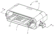
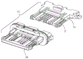
Fig. 1 is a perspective assembly view of the electrical connector of the present invention.
Fig. 2 is a perspective assembly view from another angle of fig. 1.
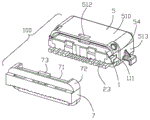
Fig. 3 is a perspective view of the electrical connector shown in fig. 2 with the waterproof portion separated.
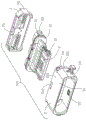
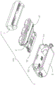
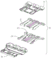
Fig. 4 is a partial exploded perspective view of the electrical connector.
Fig. 5 is a partial exploded perspective view of fig. 4 at another angle.
Fig. 6 is a partially exploded perspective view of the terminal module.
Fig. 7 is a partial exploded perspective view of fig. 6 at another angle.
Fig. 8 is an exploded perspective view of the terminal module.
Fig. 9 is an exploded perspective view of fig. 8 from another angle.
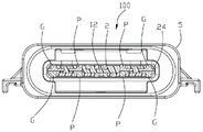
Fig. 10 is a cross-sectional view taken along line a-a of fig. 1.
[ description of main reference symbols ]
Insulating body 1 body part 1a
Contact portion 21 connecting portion 22
Widened part 25 and 26
The upper wall 510 is combined with the groove 511
Grounding part 52 of through hole 512
The abutting part 53 holds the groove 54
Upper holding part 71 of waterproof part 7
The following detailed description will further illustrate the invention in conjunction with the above-described figures.
[ detailed description ] embodiments
An embodiment of the electrical connector 100 and the method for manufacturing the same according to the present invention will be described with reference to fig. 1 to 10.
The electrical connector 100 of the present invention is a socket connector, which includes a terminal module 10, a metal shell 5 sleeved outside the terminal module 10, and a waterproof portion 7 made of glue.
The terminal module 10 includes an insulating body 1 having a base 11 and a tongue plate 12, and two rows of terminals 2 arranged on the insulating body 1 in a reverse symmetry manner.
The insulating body 1 includes a body portion 1a and an injection molding member 1b injection-molded on the body portion 1 a. The base 11 is composed of the rear end portions of both the body portion 1a and the injection-molded article 1 b. The rear end of the base 11 is provided with an L-shaped combining part 111. The tongue plate 12 is formed by the body 1a and the part of the injection-molded part 1b extending forward. A pair of ear parts 121 are arranged on two sides of the injection molding part 1 b.
Each row of terminals 2 includes two ground terminals G on both sides thereof, and a power supply terminal and a signal terminal provided inside the ground terminals G. Each of the terminals 2 includes a contact portion 21 exposed on the surface of the tongue plate 12, a tail portion 23 soldered to a circuit board (not shown), and a connecting portion 22 connected to the contact portion 21 and the tail portion 23. The ground terminal G is further provided with a latch 24 extending from the contact portion 21 for latching with the mating connector. The catching portion 24 continues forward to the front end of the contact portion 21 and extends backward to the connecting portion 22. The ground terminal G is provided with a thinned widened portion 26 at the other side of the latching portion 24, and the widened portion 26 extends from the contact portion 21 and is embedded in the tongue plate 12. The power supply terminal P is further provided with a widened portion 25 extending laterally from the contact portion 21.
The metal case 5 is provided with a cylindrical main body 51 and a plurality of grounding portions 52 protruding inward from the main body 51. The main body 51 includes an upper wall 510 and side walls 513 at both sides, and a rear edge is provided with a coupling groove 511 opened rearward. The upper wall 510 is provided with a through hole 512. A holding groove 54 penetrating the coupling groove 511 is opened on the rear side of the side wall 513.
The waterproof portion 7 has a pair of side holding portions 72, an upper holding portion 71 located between the pair of side holding portions 72, and a protruding portion 73 protruding upward from the upper holding portion 71.
Referring to fig. 1 to 10, the method for manufacturing the electrical connector 100 sequentially includes the following steps.
In a first step, two rows of terminals 2 including ground terminals G are stamped out of a metal sheet. The latch portion 24 is formed by thinning the tip portion of the ground terminal G, the widened portion 26 is formed by thinning the ground terminal G, and the contact portion 21 is formed by the non-thinned portion. The widened portion 25 is formed by thinning the tip portion of the power terminal P, and the non-thinned portion forms the contact portion 21.
Secondly, the body part 1a holding the upper row of the terminals 2 is manufactured by injection molding, and the buckling part 24 of the grounding terminal G is made to protrude out of the body part 1a laterally.
Third, the lower row of terminals 2 is abutted against the body portion 1 a. The ground terminals G in the upper row of terminals 2 are stacked and contacted with the corresponding ground terminals G in the lower row of terminals 2 in the up-down direction.
Fourthly, the insulation body 1 is manufactured through injection molding again. The injection-molded material forms the injection-molded part 1b provided with the coupling portion 111. The fastening portion 24 extends in the tongue plate 12 and is laterally exposed from the tongue plate 12. Each ear 121 is integrally formed with the latching portion 24 and covers the surface of the latching portion 24 in the vertical direction so as to latch the mating connector together with the latching portion 24. After the injection molding is completed, the bottom surface of the contact portion 21 of the ground terminal G close to the thickness center of the tongue plate 12 is made coplanar with the bottom surface of the locking portion 24 close to the thickness center of the tongue plate 12. And the buckling part 24 of the grounding terminal G extends in the tongue plate 12, so that the top surface of the buckling part far away from the thickness center of the tongue plate 12 is lower than the top surface of the contact part 21 far away from the thickness center of the tongue plate 12. The thickness of the contact portion 21 of the power terminal GP is equal to the thickness of the contact portion 21 of the ground terminal G and greater than the thickness of the contact portion 21 of the signal terminal. The sum of the thickness of the ground terminal G of the upper row of terminals 2 and the thickness of the ground terminal G of the lower row of terminals 2 is at least not less than the thickness of the tongue plate 12.
Fifthly, the metal shell 5 is manufactured through metal injection molding, and the terminal module 10 is assembled in the metal shell 5 from back to front. The base 11 of the terminal module 10 abuts against the abutting portion 53 of the metal shell 5. The coupling portion 111 is engaged with the coupling groove 511.
Sixthly, the waterproof part 7 is manufactured between the rear end of the insulating body 1 and the metal shell 5 through plastic injection through the through hole 512. The upper holding portion 71 of the waterproof portion 7 is held in the upper wall 510. The projection 73 is recessed into the through hole 512, and the side holding portion 72 is held in the holding groove 54 and flush with the side wall 513.
In other embodiments, a metal shielding plate having a fixing leg is disposed between the two rows of terminals 2. The fixing legs of the metal shielding plate extend downward from both sides of the base 11 near the joint portion 111. In this case, the ground terminal G and the power supply terminal P are both provided to have substantially the same thickness as the signal terminals. The ground terminal G and the power terminal P in the upper and lower rows of terminals 2 are no longer in stacked contact.
When the terminal module 10 is sleeved in the metal shell 5, the interference fit is formed between the terminal module and the metal shell, so that the metal shell 5 is prevented from falling off in the automatic production process, and the terminal material belt can be used for automatic production, thereby being beneficial to automatic production.
The above description is only a part of the embodiments of the present invention, and not all embodiments, and any equivalent variations of the technical solutions of the present invention, which are made by those skilled in the art through reading the present specification, are covered by the claims of the present invention.
Claims (7)
1. An electric connector comprises a terminal module and a metal shell, wherein the terminal module comprises an insulating body provided with a base and a tongue plate, and a plurality of terminals fixedly held on the insulating body, each terminal comprises a contact part and a tail part exposed out of the surface of the tongue plate, and a connecting part connected with the contact part and the tail part, and the electric connector is characterized in that: the insulating body is provided with a combination part and comprises a body part for fixing the terminal and an injection molding part which is formed on the body part by injection molding again, the combination parts are arranged on two sides of the injection molding part in a pair, the metal shell is provided with a combination groove and a retaining groove communicated with the combination groove, the combination groove penetrates backwards from the rear edge of the metal shell to form an opening, the combination part is combined with the combination groove when the terminal module is assembled on the metal shell from back to front, the combination part is L-shaped and comprises a horizontal part fixed in the combination groove and a vertical part formed by extending downwards from the rear end of the horizontal part, the vertical part is abutted against the rear edge of the metal shell and located below the combination groove, and the electric connector further comprises a waterproof part which is provided with a retaining part which is retained in the retaining groove.
2. The electrical connector of claim 1, wherein: the metal shell is made by metal powder injection.
3. The electrical connector of claim 1, wherein: the metal shell is provided with an upper wall, a side wall and a retaining groove arranged behind the side wall, the retaining part of the waterproof part is provided with a pair of side retaining parts positioned at two sides and an upper retaining part positioned between the pair of side retaining parts, the upper retaining part of the waterproof part is retained in the upper wall, and the side retaining parts are retained in the retaining groove and are flush with the side wall of the metal shell.
4. The electrical connector of claim 3, wherein: the upper wall of the metal shell is provided with a through hole, and the waterproof part is manufactured between the rear end of the insulating body and the metal shell through plastic injection molding of the through hole.
5. The electrical connector of claim 1, wherein: the electric connector comprises a metal shielding sheet arranged between the two rows of terminals, the metal shielding sheet is provided with a pair of fixing feet, and the fixing feet are positioned at the position, close to the combining part, of the base.
6. A method of manufacturing an electrical connector comprising the steps of:
a. the terminal module is manufactured by injection molding, and comprises an insulating body fixedly holding a plurality of terminals, wherein the insulating body is provided with a combination part which is L-shaped and comprises a horizontal part and a vertical part formed by extending downwards from the rear end of the horizontal part, and each terminal is provided with a contact part, a connecting part and a tail part;
b. the terminal module is characterized in that a metal shell is manufactured through metal powder injection molding, the metal shell is provided with a combination groove and a retaining groove communicated with the combination groove, the terminal module is assembled in the metal shell from back to front, the combination part is matched with the combination groove, the horizontal part of the combination part is fixedly held in the combination groove, and the vertical part is attached to the rear edge of the metal shell and is positioned below the combination groove;
and c, performing plastic injection molding between the rear end of the terminal module and the metal shell to obtain a waterproof part after the step b, wherein the waterproof part is provided with a holding part, and the holding part is held in the holding groove.
7. The method of manufacturing an electrical connector of claim 6, wherein: and a step a of manufacturing a body part fixedly holding one row of terminals by injection molding for the first time, then enabling the other row of terminals to abut against the body part, manufacturing an injection molding part fixedly holding two rows of terminals by injection molding again, and enabling the combining part to be arranged on the injection molding part.
Priority Applications (4)
| Application Number | Priority Date | Filing Date | Title |
|---|---|---|---|
| CN201610455661.2A CN107528165B (en) | 2016-06-22 | 2016-06-22 | Electric connector and manufacturing method thereof |
| TW105123981A TWI704729B (en) | 2016-06-22 | 2016-07-29 | Electrical connector and method of making the same |
| US15/629,771 US10218125B2 (en) | 2016-06-22 | 2017-06-22 | Electrical connector having interlocked shell and housing portions and stacked grounding terminals |
| US15/640,460 US10170863B2 (en) | 2016-06-22 | 2017-07-01 | Electrical connector |
Applications Claiming Priority (1)
| Application Number | Priority Date | Filing Date | Title |
|---|---|---|---|
| CN201610455661.2A CN107528165B (en) | 2016-06-22 | 2016-06-22 | Electric connector and manufacturing method thereof |
Publications (2)
| Publication Number | Publication Date |
|---|---|
| CN107528165A CN107528165A (en) | 2017-12-29 |
| CN107528165B true CN107528165B (en) | 2020-06-30 |
Family
ID=60677107
Family Applications (1)
| Application Number | Title | Priority Date | Filing Date |
|---|---|---|---|
| CN201610455661.2A Active CN107528165B (en) | 2016-06-22 | 2016-06-22 | Electric connector and manufacturing method thereof |
Country Status (3)
| Country | Link |
|---|---|
| US (1) | US10218125B2 (en) |
| CN (1) | CN107528165B (en) |
| TW (1) | TWI704729B (en) |
Families Citing this family (7)
| Publication number | Priority date | Publication date | Assignee | Title |
|---|---|---|---|---|
| US10170863B2 (en) * | 2016-06-22 | 2019-01-01 | Foxconn Interconnect Technology Limited | Electrical connector |
| CN206441936U (en) * | 2016-11-30 | 2017-08-25 | 富士康(昆山)电脑接插件有限公司 | Electric connector |
| CN206834365U (en) * | 2016-12-27 | 2018-01-02 | 富誉电子科技(淮安)有限公司 | Electric connector |
| JP6230013B1 (en) * | 2017-04-07 | 2017-11-15 | Smk株式会社 | Electrical connector |
| CN109256643B (en) * | 2018-11-07 | 2024-04-19 | 温州意华接插件股份有限公司 | High-speed connector module |
| CN209169525U (en) * | 2018-12-18 | 2019-07-26 | 富鼎精密工业(郑州)有限公司 | Electric connector |
| US10873159B1 (en) | 2019-05-29 | 2020-12-22 | Amphenol Corporation | Electrical connector wafer assembly |
Citations (10)
| Publication number | Priority date | Publication date | Assignee | Title |
|---|---|---|---|---|
| JP2003115357A (en) * | 2001-10-01 | 2003-04-18 | Yazaki Corp | Electromagnetic wave shielding structure equipped with waterproofing nature |
| CN104183962A (en) * | 2013-05-23 | 2014-12-03 | 富士康(昆山)电脑接插件有限公司 | electrical connector and combination thereof |
| CN104868320A (en) * | 2014-05-22 | 2015-08-26 | 连展科技电子(昆山)有限公司 | Socket electric connector and plug electric connector |
| CN105281086A (en) * | 2014-07-11 | 2016-01-27 | 富士康(昆山)电脑接插件有限公司 | Electric connector and manufacturing method thereof |
| CN105281090A (en) * | 2014-07-11 | 2016-01-27 | 富士康(昆山)电脑接插件有限公司 | Electric connector and manufacturing method thereof |
| CN105406241A (en) * | 2015-11-10 | 2016-03-16 | 富士康(昆山)电脑接插件有限公司 | Electric connector and manufacturing method thereof |
| CN105470697A (en) * | 2015-04-02 | 2016-04-06 | 富士康(昆山)电脑接插件有限公司 | Electrical connector and manufacturing method thereof |
| CN205211994U (en) * | 2014-10-30 | 2016-05-04 | 富士康(昆山)电脑接插件有限公司 | Electric connector |
| CN105655787A (en) * | 2016-01-18 | 2016-06-08 | 富士康(昆山)电脑接插件有限公司 | Electric connector and manufacturing method thereof |
| CN105655808A (en) * | 2015-04-21 | 2016-06-08 | 富士康(昆山)电脑接插件有限公司 | Electric connector |
Family Cites Families (14)
| Publication number | Priority date | Publication date | Assignee | Title |
|---|---|---|---|---|
| US8814443B2 (en) * | 2009-06-02 | 2014-08-26 | Hon Hai Precision Industry Co., Ltd. | Connector with improved fastening structures for fastening two tongues thereof together |
| US8708745B2 (en) | 2011-11-07 | 2014-04-29 | Apple Inc. | Dual orientation electronic connector |
| KR20140061942A (en) | 2012-11-14 | 2014-05-22 | 타이코에이엠피(유) | Connector module |
| US9502821B2 (en) * | 2013-07-19 | 2016-11-22 | Foxconn Interconnect Technology Limited | Flippable electrical connector |
| US9281626B2 (en) * | 2014-06-13 | 2016-03-08 | Lotes Co., Ltd | Mating connector |
| CN105470714A (en) * | 2014-09-03 | 2016-04-06 | 凡甲电子(苏州)有限公司 | Electric connector |
| US20160104957A1 (en) | 2014-10-10 | 2016-04-14 | Tyco Electronics Amp Korea Ltd | Connector Assembly |
| CN204118317U (en) | 2014-10-15 | 2015-01-21 | 昆山全方位电子科技有限公司 | There is USB 3.1 socket connector of side shell fragment |
| CN204243365U (en) | 2014-10-27 | 2015-04-01 | 富士康(昆山)电脑接插件有限公司 | Electric connector |
| CN204516985U (en) * | 2014-11-10 | 2015-07-29 | 连展科技电子(昆山)有限公司 | The socket connector of the forward and reverse grafting of pin connector can be accepted |
| CN204118373U (en) | 2014-11-14 | 2015-01-21 | 泰科电子(上海)有限公司 | Electric connector |
| CN204315771U (en) | 2014-11-14 | 2015-05-06 | 富士康(昆山)电脑接插件有限公司 | Electric connector |
| CN204424577U (en) * | 2015-03-26 | 2015-06-24 | 上海莫仕连接器有限公司 | Electric connector |
| CN105024197B (en) | 2015-06-05 | 2018-04-17 | 昆山全方位电子科技有限公司 | A kind of USB connector based on TypeC |
-
2016
- 2016-06-22 CN CN201610455661.2A patent/CN107528165B/en active Active
- 2016-07-29 TW TW105123981A patent/TWI704729B/en active
-
2017
- 2017-06-22 US US15/629,771 patent/US10218125B2/en active Active
Patent Citations (10)
| Publication number | Priority date | Publication date | Assignee | Title |
|---|---|---|---|---|
| JP2003115357A (en) * | 2001-10-01 | 2003-04-18 | Yazaki Corp | Electromagnetic wave shielding structure equipped with waterproofing nature |
| CN104183962A (en) * | 2013-05-23 | 2014-12-03 | 富士康(昆山)电脑接插件有限公司 | electrical connector and combination thereof |
| CN104868320A (en) * | 2014-05-22 | 2015-08-26 | 连展科技电子(昆山)有限公司 | Socket electric connector and plug electric connector |
| CN105281086A (en) * | 2014-07-11 | 2016-01-27 | 富士康(昆山)电脑接插件有限公司 | Electric connector and manufacturing method thereof |
| CN105281090A (en) * | 2014-07-11 | 2016-01-27 | 富士康(昆山)电脑接插件有限公司 | Electric connector and manufacturing method thereof |
| CN205211994U (en) * | 2014-10-30 | 2016-05-04 | 富士康(昆山)电脑接插件有限公司 | Electric connector |
| CN105470697A (en) * | 2015-04-02 | 2016-04-06 | 富士康(昆山)电脑接插件有限公司 | Electrical connector and manufacturing method thereof |
| CN105655808A (en) * | 2015-04-21 | 2016-06-08 | 富士康(昆山)电脑接插件有限公司 | Electric connector |
| CN105406241A (en) * | 2015-11-10 | 2016-03-16 | 富士康(昆山)电脑接插件有限公司 | Electric connector and manufacturing method thereof |
| CN105655787A (en) * | 2016-01-18 | 2016-06-08 | 富士康(昆山)电脑接插件有限公司 | Electric connector and manufacturing method thereof |
Also Published As
| Publication number | Publication date |
|---|---|
| US20170373438A1 (en) | 2017-12-28 |
| TWI704729B (en) | 2020-09-11 |
| US10218125B2 (en) | 2019-02-26 |
| TW201801413A (en) | 2018-01-01 |
| CN107528165A (en) | 2017-12-29 |
Similar Documents
| Publication | Publication Date | Title |
|---|---|---|
| CN107528165B (en) | Electric connector and manufacturing method thereof | |
| CN107565241B (en) | Electrical connector | |
| US9774130B2 (en) | Waterproof electrical connector | |
| CN107681371B (en) | Electrical connector | |
| TWI657624B (en) | Electrical connector and method of making the same | |
| US9112299B2 (en) | Waterproof electrical connector and method for making the same | |
| CN107305985B (en) | Electric connector and manufacturing method thereof | |
| TW201801418A (en) | Electrical connector and method of making the same | |
| US20160141805A1 (en) | Receptacle connector having improved insulative housing | |
| US9130301B2 (en) | Waterproof electrical connector and method for making the same | |
| WO2016004895A1 (en) | Electrical connector and cable connector having same | |
| US9837734B2 (en) | Electrical connector having inetrengaged grounding contacts | |
| US20160006195A1 (en) | Electrical connector assembly with metallic plate and method of manufacturing the same | |
| TWM461179U (en) | Electrical connector socket and plug | |
| US20100248545A1 (en) | Electrical connector featured usb/esata interfaces | |
| US7963777B2 (en) | First connector, second connector, and electrical connecting device | |
| CN106898902B (en) | Electrical connector | |
| CN109301570B (en) | Electric connector | |
| CN107017501B (en) | Electric connector | |
| CN211404800U (en) | Positive reverse plug USB socket | |
| TWM514134U (en) | Electrical connector assembly and electric equipment | |
| CN214542605U (en) | Simple USB socket | |
| CN210744234U (en) | Positive reverse plug USB plug | |
| US9722383B2 (en) | Electrical connector having insulative housing and method of making the same | |
| CN218648242U (en) | Anti-drop's double-end female seat connector |
Legal Events
| Date | Code | Title | Description |
|---|---|---|---|
| PB01 | Publication | ||
| PB01 | Publication | ||
| SE01 | Entry into force of request for substantive examination | ||
| SE01 | Entry into force of request for substantive examination | ||
| GR01 | Patent grant | ||
| GR01 | Patent grant |