CN107407812B - Image display device - Google Patents
Image display device Download PDFInfo
- Publication number
- CN107407812B CN107407812B CN201680013611.7A CN201680013611A CN107407812B CN 107407812 B CN107407812 B CN 107407812B CN 201680013611 A CN201680013611 A CN 201680013611A CN 107407812 B CN107407812 B CN 107407812B
- Authority
- CN
- China
- Prior art keywords
- image
- light
- optical system
- eye
- display device
- Prior art date
- Legal status (The legal status is an assumption and is not a legal conclusion. Google has not performed a legal analysis and makes no representation as to the accuracy of the status listed.)
- Active
Links
- 230000003287 optical effect Effects 0.000 claims abstract description 107
- 210000001508 eye Anatomy 0.000 abstract description 15
- 210000001747 pupil Anatomy 0.000 description 17
- 230000004438 eyesight Effects 0.000 description 12
- 238000010586 diagram Methods 0.000 description 10
- 206010020675 Hypermetropia Diseases 0.000 description 9
- 239000004065 semiconductor Substances 0.000 description 5
- 208000001491 myopia Diseases 0.000 description 4
- 239000013307 optical fiber Substances 0.000 description 4
- 230000004075 alteration Effects 0.000 description 3
- 238000012937 correction Methods 0.000 description 3
- 238000001514 detection method Methods 0.000 description 3
- 210000003128 head Anatomy 0.000 description 3
- 230000004379 myopia Effects 0.000 description 3
- 230000004907 flux Effects 0.000 description 2
- 239000011521 glass Substances 0.000 description 2
- 230000004305 hyperopia Effects 0.000 description 2
- 201000006318 hyperopia Diseases 0.000 description 2
- 238000000034 method Methods 0.000 description 2
- 210000001525 retina Anatomy 0.000 description 2
- 238000013459 approach Methods 0.000 description 1
- 201000009310 astigmatism Diseases 0.000 description 1
- 230000002146 bilateral effect Effects 0.000 description 1
- 210000005252 bulbus oculi Anatomy 0.000 description 1
- 230000008859 change Effects 0.000 description 1
- 239000003086 colorant Substances 0.000 description 1
- 238000004891 communication Methods 0.000 description 1
- 210000005069 ears Anatomy 0.000 description 1
- 238000005401 electroluminescence Methods 0.000 description 1
- 208000013057 hereditary mucoepithelial dysplasia Diseases 0.000 description 1
- 239000004973 liquid crystal related substance Substances 0.000 description 1
- 238000012986 modification Methods 0.000 description 1
- 230000004048 modification Effects 0.000 description 1
- 229920003023 plastic Polymers 0.000 description 1
- 238000007740 vapor deposition Methods 0.000 description 1
- 230000004304 visual acuity Effects 0.000 description 1
Images


Classifications
-
- G—PHYSICS
- G02—OPTICS
- G02B—OPTICAL ELEMENTS, SYSTEMS OR APPARATUS
- G02B27/00—Optical systems or apparatus not provided for by any of the groups G02B1/00 - G02B26/00, G02B30/00
- G02B27/02—Viewing or reading apparatus
- G02B27/022—Viewing apparatus
- G02B27/024—Viewing apparatus comprising a light source, e.g. for viewing photographic slides, X-ray transparancies
- G02B27/026—Viewing apparatus comprising a light source, e.g. for viewing photographic slides, X-ray transparancies and a display device, e.g. CRT, LCD, for adding markings or signs or to enhance the contrast of the viewed object
-
- G—PHYSICS
- G02—OPTICS
- G02B—OPTICAL ELEMENTS, SYSTEMS OR APPARATUS
- G02B27/00—Optical systems or apparatus not provided for by any of the groups G02B1/00 - G02B26/00, G02B30/00
- G02B27/01—Head-up displays
- G02B27/017—Head mounted
- G02B27/0172—Head mounted characterised by optical features
-
- G—PHYSICS
- G02—OPTICS
- G02B—OPTICAL ELEMENTS, SYSTEMS OR APPARATUS
- G02B13/00—Optical objectives specially designed for the purposes specified below
- G02B13/001—Miniaturised objectives for electronic devices, e.g. portable telephones, webcams, PDAs, small digital cameras
- G02B13/0015—Miniaturised objectives for electronic devices, e.g. portable telephones, webcams, PDAs, small digital cameras characterised by the lens design
- G02B13/002—Miniaturised objectives for electronic devices, e.g. portable telephones, webcams, PDAs, small digital cameras characterised by the lens design having at least one aspherical surface
- G02B13/0035—Miniaturised objectives for electronic devices, e.g. portable telephones, webcams, PDAs, small digital cameras characterised by the lens design having at least one aspherical surface having three lenses
-
- G—PHYSICS
- G02—OPTICS
- G02B—OPTICAL ELEMENTS, SYSTEMS OR APPARATUS
- G02B17/00—Systems with reflecting surfaces, with or without refracting elements
- G02B17/08—Catadioptric systems
-
- G—PHYSICS
- G02—OPTICS
- G02B—OPTICAL ELEMENTS, SYSTEMS OR APPARATUS
- G02B27/00—Optical systems or apparatus not provided for by any of the groups G02B1/00 - G02B26/00, G02B30/00
- G02B27/02—Viewing or reading apparatus
- G02B27/06—Viewing or reading apparatus with moving picture effect
-
- G—PHYSICS
- G02—OPTICS
- G02B—OPTICAL ELEMENTS, SYSTEMS OR APPARATUS
- G02B5/00—Optical elements other than lenses
- G02B5/08—Mirrors
- G02B5/09—Multifaceted or polygonal mirrors, e.g. polygonal scanning mirrors; Fresnel mirrors
-
- G—PHYSICS
- G02—OPTICS
- G02B—OPTICAL ELEMENTS, SYSTEMS OR APPARATUS
- G02B5/00—Optical elements other than lenses
- G02B5/08—Mirrors
- G02B5/10—Mirrors with curved faces
-
- G—PHYSICS
- G02—OPTICS
- G02B—OPTICAL ELEMENTS, SYSTEMS OR APPARATUS
- G02B27/00—Optical systems or apparatus not provided for by any of the groups G02B1/00 - G02B26/00, G02B30/00
- G02B27/01—Head-up displays
- G02B27/0149—Head-up displays characterised by mechanical features
- G02B2027/0154—Head-up displays characterised by mechanical features with movable elements
-
- G—PHYSICS
- G02—OPTICS
- G02B—OPTICAL ELEMENTS, SYSTEMS OR APPARATUS
- G02B27/00—Optical systems or apparatus not provided for by any of the groups G02B1/00 - G02B26/00, G02B30/00
- G02B27/01—Head-up displays
- G02B27/017—Head mounted
- G02B27/0172—Head mounted characterised by optical features
- G02B2027/0174—Head mounted characterised by optical features holographic
-
- G—PHYSICS
- G02—OPTICS
- G02B—OPTICAL ELEMENTS, SYSTEMS OR APPARATUS
- G02B27/00—Optical systems or apparatus not provided for by any of the groups G02B1/00 - G02B26/00, G02B30/00
- G02B27/01—Head-up displays
- G02B27/017—Head mounted
- G02B2027/0178—Eyeglass type
-
- G—PHYSICS
- G02—OPTICS
- G02B—OPTICAL ELEMENTS, SYSTEMS OR APPARATUS
- G02B27/00—Optical systems or apparatus not provided for by any of the groups G02B1/00 - G02B26/00, G02B30/00
- G02B27/02—Viewing or reading apparatus
- G02B27/028—Viewing or reading apparatus characterised by the supporting structure
Landscapes
- Physics & Mathematics (AREA)
- General Physics & Mathematics (AREA)
- Optics & Photonics (AREA)
Abstract
Provided is an image display device capable of easily adjusting the visibility for a virtual image. An image display device according to the present invention includes: an image generating unit that emits image light including image information; a 1 st optical system that condenses image light to form an intermediate image; a 2 nd optical system that deflects light from the intermediate image, guides the virtual image to the eyes of the observer, and transmits external light to be guided to the eyes of the observer; and an intermediate image position changing unit that adjusts the position of the virtual image in the depth direction by changing the position of the intermediate image.
Description
Technical Field
The present invention relates to an image display device.
Background
In recent years, attention has been paid to wearable image display devices such as head mounted displays. As such a head-mounted display, a transparent (sethrough) head-mounted display is known, which can simultaneously observe an image (virtual image) from a display element and an image (external light) of the outside world (see, for example, patent document 1).
With this transparent image display device, even a wearer with myopia, hyperopia, or the like can adjust the visibility of external light to improve the visibility of external light.
Documents of the prior art
Patent document
Patent document 1: japanese patent laid-open publication No. 2013-186230
Disclosure of Invention
Problems to be solved by the invention
When a wearer of myopia, hyperopia, or the like uses the transparent image display device, the wearer also needs to perform adjustment of the visibility of the virtual image (adjustment of the position of the virtual image in the depth direction). However, the above-described prior art does not consider the adjustment of the visibility for the virtual image. Therefore, it is desirable to provide a new technique capable of easily performing the adjustment of the degree of vision for a virtual image.
The present invention has been made in view of such circumstances, and an object thereof is to provide an image display device capable of easily adjusting the degree of visibility for a virtual image.
Means for solving the problems
According to the 1 st aspect of the present invention, there is provided an image display device comprising: an image generating unit that emits image light including image information; a 1 st optical system that condenses the image light to form an intermediate image; a 2 nd optical system that deflects light from the intermediate image to guide a virtual image to an eye of an observer, and transmits external light to guide the external light to the eye of the observer; and an intermediate image position changing unit that adjusts a position in the depth direction of the virtual image by changing a position of the intermediate image.
According to the image display device of the 1 st aspect, the adjustment of the visibility for the virtual image can be performed with a simple configuration in which the position of the intermediate image is changed.
In the above-described aspect 1, the image generating unit may include: an optical scanning device that scans light emitted from the light source section; and an enlarging element that enlarges light from the optical scanning device and emits the light as the image light, wherein the intermediate image position changing means moves at least a part of the 1 st optical system in a direction of a central ray of the image light.
With this configuration, the image generating unit can be downsized. Further, since the intermediate image position changing means moves at least a part of the 1 st optical system, the apparatus configuration can be simplified and the apparatus can be made compact. This makes it possible to reduce the size of the entire device.
In the above-described aspect 1, the image generating unit may include an electro-optical device that generates the image light, and the intermediate image position changing unit may move at least a part of the 1 st optical system in a direction of a central ray of the image light.
According to this configuration, since the intermediate image position changing means moves at least a part of the 1 st optical system, the apparatus configuration can be simplified and the apparatus can be made compact. This makes it possible to reduce the size of the entire device.
According to the 2 nd aspect of the present invention, there is provided an image display device comprising: an image generating unit that emits image light including image information; a 1 st optical system that condenses the image light to form an intermediate image; a 2 nd optical system that deflects light from the intermediate image, guides a virtual image to an eye of an observer, and transmits external light to be guided to the eye of the observer; a visibility adjustment unit that adjusts a visibility for the external light; and an intermediate image position changing unit that adjusts a position in the depth direction of the virtual image by changing a position of the intermediate image.
According to the image display device of the 2 nd aspect, the position adjustment in the depth direction of the virtual image (the adjustment of the visibility of the virtual image) can be performed with a simple configuration in which the position of the intermediate image is changed. Furthermore, the adjustment of the visibility (viewer scale) for the external light can be performed.
In the above-described 2 nd aspect, the intermediate image position changing means may be configured to move the image generating unit and at least a part of the 1 st optical system integrally in a direction of a central ray of the image light.
With this configuration, the position of the intermediate image can be easily and reliably changed.
In the above-described 2 nd aspect, the intermediate image position changing means may be configured to move at least a part of the 1 st optical system in a direction of a central ray of the image light.
According to this configuration, since the intermediate image position changing means moves at least a part of the 1 st optical system, the apparatus configuration can be simplified and the apparatus can be made compact. This makes it possible to reduce the size of the entire device.
In the above-described 2 nd aspect, the visibility adjustment unit may be configured to be a lens formed by an external light side surface of the 2 nd optical system and an eye side surface of the observer.
With this configuration, the visibility adjusting unit and the 2 nd optical system can be used in combination. This reduces the number of components and reduces the size of the device.
In the above-described 2 nd aspect, the visibility adjustment means may be configured by a spectacle lens disposed between the 2 nd optical system and the eyes of the observer.
According to this configuration, since the eyeglass lens is used, the device can be made compact and the visibility of the external light can be easily adjusted.
In the above-described 2 nd aspect, the intermediate image position changing means may be configured to adjust the position of the virtual image in the depth direction in accordance with the adjustment of the visibility of the external light by the visibility adjusting means.
According to this configuration, the visibility for the external light and the virtual image can be adjusted in a well-balanced manner, and therefore, an image display device excellent in visibility can be provided.
Drawings
Fig. 1 is a diagram showing a state in which the HMD according to embodiment 1 is worn.
Fig. 2 is a perspective view of the HMD according to this embodiment.
Fig. 3 is a plan view showing the structure of each part of the display device.
Fig. 4 is a diagram illustrating a structure of the HMD.
Fig. 5 is a diagram illustrating a case where a diopter adjustment is performed for a viewer with myopia.
Fig. 6 is a diagram illustrating a case where the diopter adjustment is performed for a viewer with far vision.
Fig. 7 is a diagram showing a schematic configuration of the HMD according to embodiment 2.
Detailed Description
Hereinafter, embodiments of the present invention will be described in detail with reference to the drawings.
In the drawings used in the following description, for the sake of easy understanding of the features, the features may be shown enlarged and the dimensional ratios of the respective components are not necessarily the same as the actual ones.
Hereinafter, an embodiment of the present invention will be described with reference to the drawings.
The image display device of the present embodiment is an example of a head-mounted display used by a user wearing the head.
In the following description, a Head Mounted Display (HMD) will be simply referred to as HMD.
Fig. 1 is a diagram showing a state in which a user wears the HMD according to this embodiment.
Fig. 2 is a perspective view of the HMD according to this embodiment.
As shown in fig. 1, the HMD 300 of the present embodiment is used by a user wearing the HMD on the head with a sense of wearing glasses. The HMD 300 of the present embodiment is a transparent (transmissive) HMD. According to the HMD 300 of the present embodiment, the user can observe the image generated by the image display unit and can observe an external image such as a scene outside the HMD 300.
As shown in fig. 2, HMD 300 includes: a display device 100 having a shape similar to glasses; and a control device (controller) 200 having a size of a degree that can be held by a user. The display device 100 and the control device 200 are connected to each other so as to communicate with each other by wire or wirelessly. In the present embodiment, the left-eye image display unit 110A and the right-eye image display unit 110B constituting the display device 100 are each connected to the control device 200 so as to be capable of wired communication via the cable 150, and communicate an image signal and a control signal.
The display device 100 includes a main frame 120, a left-eye image display unit 110A, and a right-eye image display unit 110B. The control device 200 includes a display unit 210 and an operation button unit 250. The display unit 210 displays various information, instructions, and the like to be transmitted to the user, for example. The main frame 120 has a pair of temple portions 122A, 122B for a user to hang on the ears. The main frame 120 is a member that supports the left-eye image display unit 110A and the right-eye image display unit 110B.
Fig. 3 is a plan view showing the structure of each part of the display device 100. Fig. 3 shows a state when the user wearing the display device 100 is viewed from the head.
The right-eye image display unit 110B and the left-eye image display unit 110A have the same configuration, and the respective components in both image display units are arranged in bilateral symmetry. Therefore, the right-eye image display unit 110B will be simply referred to as the image display unit 110 to be described in detail below, and the description of the left-eye image display unit 110A will be omitted.
As shown in fig. 3, the image display unit 110 includes an image generating unit 11, a pupil enlarging element 12, a 1 st optical system 13, and a 2 nd optical system 14. The image generator 11 emits light including image information. The pupil expander 12 expands the beam diameter of light emitted from an optical scanning device 17 described below.
The image generating unit 11 includes a light source optical system 15, a mirror 16, and an optical scanning device 17. The light source optical system 15 emits light generated by an internal semiconductor laser. The reflecting mirror 16 reflects the light emitted from the light source optical system 15 and returns the optical path of the light. The optical scanning device 17 scans the light reflected by the reflecting mirror 16.
The light source optical system 15 includes a light source unit 25, a pickup lens 26, an optical fiber 27, and a collimator lens 28. The light source unit 25 includes, for example, a plurality of solid-state light sources (not shown) including a semiconductor laser that emits red light, a semiconductor laser that emits green light, and a semiconductor laser that emits blue light. The light of each color emitted from each semiconductor laser is modulated in accordance with an image signal, and the modulated light of each color is synthesized and emitted as image light from the light source section 25. The pickup lens 26 transmits the light emitted from the light source unit 25 to the optical fiber 27 at the subsequent stage. The optical fiber 27 guides light incident from the light source section 25 through the pickup lens 26 to an optical system of a subsequent stage. The collimator lens 28 collimates light incident from the optical fiber 27.
The light emitted from the light source optical system 15 is reflected by a mirror 16, and the light path is reflected and guided to the optical scanning device 17. The optical scanning device 17 includes, for example, a MEMS mirror (not shown). The optical scanning device 17 changes the posture of the MEMS mirror in accordance with the modulation operation of the light source optical system 15, and two-dimensionally scans the light. Thus, the optical scanning device 17 emits image light including image information.
The light emitted from the light source optical system 15 is collimated by the collimator lens 28 to become parallel light. The collimated light angle is converted by the MEMS mirror 18 of the optical scanning device 17 to constitute image light. The image light whose angle is converted by the MEMS mirror 18 enters the pupil enlarging element 12.
Considering the size of the pupil of the eye pupil of the observer H, the movement of the eyeball, the individual difference in the width of the eye, and the like, it is considered that the size of the exit pupil generally needs to be about 6 to 8 mm. In the HMD 300 of the present embodiment, the light (image light) from the MEMS mirror 18 is amplified to 6mm or more by the pupil expander 12. This makes it possible to observe the virtual image G1 well even if the eye pupil position of the observer H is slightly shifted, and the usability is very excellent.
The pupil enlarging element 12 has a plurality of parallel plane plates (not shown) and a plurality of half mirrors (not shown). A plurality of parallel flat plates are joined by a half mirror. The pupil enlarging element 12 is cut so that a pair of end faces constituting a light incident end face 12a on which image light from the optical scanning device 17 is incident and a light emitting end face 12b which enlarges the image light and emits the image light are inclined with respect to the thickness direction of the parallel plane plate. Thus, the horizontal sectional shape of the pupil enlarging element 12 is trapezoidal.
In the pupil expander 12, the image light incident from the light incident end surface 12a is repeatedly transmitted and reflected by the half mirrors 24b, and then exits from the light exit end surface 12 b. The width of the image light emitted from the light emitting end surface 12b is enlarged relative to the width of the image light incident on the light incident end surface 12 a. The incident angle of the image light toward the light incident end surface 12a matches the emission angle of the image light from the light emission end surface 12 b.
Therefore, for example, image light incident perpendicularly to the light incident end surface 12a is emitted perpendicularly from the light emitting end surface 12b, and image light incident at a predetermined incident angle with respect to the light incident end surface 12a is emitted at an emission angle equal to the incident angle from the light emitting end surface 12 b. Thus, in fig. 3, when the image light passes through the pupil enlarging element 12, the optical path is bent toward the short side of the trapezoid.
The 1 st optical system 13 receives light emitted from the pupil expander 12 and functions as a correction optical system that corrects aberration and distortion of an image generated by the 2 nd optical system 14. The 1 st optical system 13 is an optical system including at least positive and negative refractive powers, and has a positive refractive power as a whole. In the present embodiment, the 1 st optical system 13 includes a 1 st lens 21, a 2 nd lens 22, and a 3 rd lens 23 in this order from the light incident side. In the present embodiment, the 1 st optical system 13 is configured by three lenses, i.e., the 1 st lens 21, the 2 nd lens 22, and the 3 rd lens 23, but the number of lenses is not particularly limited.
With this configuration, since the 1 st optical system 13 has a positive refractive power as a whole, light emitted from the pupil expander 12 can be converged to form an intermediate image GM in front of the 2 nd optical system 14.
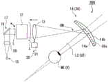
Fig. 4 is a schematic diagram of the structure of the HMD 300 of the present embodiment. In addition, in fig. 4, the 1 st optical system 13 is shown as 1 lens for easy view of the drawing.
As shown in fig. 4, the 2 nd optical system 14 reflects the light from the intermediate image, guides the virtual image G1 to the eye ME of the observer H, and transmits a part of the external light. For example, a concave mirror formed by vapor deposition of a translucent film, a fresnel concave mirror, a structure in which a reflection type hologram element is formed on an aspherical surface, and the like are used as the 2 nd optical system 14. The 2 nd optical system 14 of the present embodiment has a structure in which, for example, a translucent concave mirror (reflecting surface) 36a is provided in a lens 36 (transparent plastic) formed of an eye-side surface 14a and an external light-side surface 14 b.
In addition, the eyesight of viewers using an HMD varies from person to person. For example, in the case where an observer other than ordinary vision uses an HMD in the near vision, astigmatism, or the like, it is required to perform a diopter adjustment for external light and a virtual image so as to obtain good image viewability.
The HMD 300 of the present embodiment can easily adjust the visibility for the external light and the virtual image as will be described later.
The HMD 300 of the present embodiment includes a visibility adjustment unit 35 that adjusts the visibility for external light. The diopter adjusting unit 35 is constituted by a lens 36, and the lens 36 is formed by the eye-side surface 14a and the external light-side surface 14b of the 2 nd optical system 14. The lens 36 constitutes a visibility adjustment unit described in claims, which adjusts the visibility for external light by adjusting the shape in accordance with the eyesight of the observer. And (6) carrying out correction.
Hereinafter, a method of determining the shape of the lens 36 will be described.
First, the arrangement, refractive index, and shape of the 1 st optical system 13 and the 2 nd optical system 14 are determined so as to reduce the aberration of the virtual image G1. In this case, generally, the 2 nd optical system 14 (lens 36) is formed into a free-form surface, whereby aberrations can be corrected more favorably. After the shape of each curved surface of the eye-side surface 14a and the concave mirror 37 is determined, the curved surface shape of the external light-side surface 14b is determined so that necessary diopter correction can be performed.
For example, the viewer H who has normal vision may set the visual acuity adjustment amount of the external light to 0. That is, the shapes of the eye-side surface 14a and the external light-side surface 14b are adjusted so as to have no refractive power for external light. That is, the average radius of curvature of the eye-side surface 14a is set to a value slightly larger than the average curvature of the outer light-side surface 14 b.
Further, for a myopic observer H, the following lenses 36 may be used: the average radius of curvature of the outer-light-side surface 14b of the lens 36 is larger than the average radius of curvature of the eye-side surface 14a, and has a negative refractive power as a whole.
Further, for the viewer H who is far-sighted, the following lenses 36 may be used: the outer light-side surface 14b of the lens 36 has an average radius of curvature smaller than that of the eye-side surface 14a, and has a positive refractive power as a whole. Further, the lens 36 may be a dual-purpose lens used as a progressive-focus lens. The adjustment of the visibility of the external light may be performed independently of the visibility and position of the virtual image G1 described later.
The lens 36 (the 2 nd optical system 14) can be attached to and detached from the main frame 120 (see fig. 3). Therefore, by replacing the lens 36 corresponding to the eyesight, the observer H having various eyesight can observe the external light well.
The HMD 300 according to this embodiment further includes an intermediate image position changing unit 30, and the intermediate image position changing unit 30 adjusts the position in the depth direction of the virtual image G1 by changing the position of the intermediate image GM, thereby adjusting the degree of vision with respect to the virtual image G1. The intermediate image position changing unit 30 includes a moving device 31, and the moving device 31 moves the 1 st optical system 13 in the direction of the central ray of the light (image light L) emitted from the pupil expander 12.
Examples of the moving device 31 include a moving device that moves the 1 st optical system 13 by using a screw or an eccentric pin along a guide, and a moving device that automatically moves the 1 st optical system 13 by using a motor, an actuator, or the like.
In the present embodiment, the 1 st optical system 13 is configured by a plurality of lenses (the 1 st lens 21, the 2 nd lens 22, and the 3 rd lens 23). The intermediate image position changing means 30 may move the entire 1 st optical system 13 (three lenses), or may move only one of the three lenses.
The following describes the visibility adjustment function for the virtual image G1.
First, a case where the adjustment of the visibility of the virtual image is performed for the observer H who is myopic will be described. In addition, virtual image visibility adjustment is performed in correspondence with external light visibility adjustment achieved based on the visibility adjustment unit 35. That is, when the virtual image position adjustment is performed in accordance with the observer H with short sight, the lens 36 for short sight corresponding to the observer H with short sight may be used.
Fig. 5 is a diagram illustrating a case where the diopter adjustment is performed for the observer H who is myopic. In addition, fig. 4 shows only the light flux in the center of the image (virtual image G1).
As shown in fig. 5, the moving device 31 moves the 1 st optical system 13 so as to approach the 2 nd optical system 14 side. Thereby, the position of the intermediate image GM is brought close to the 2 nd optical system 14. This makes the light from the intermediate image GM reflected by the 2 nd optical system 14 become divergent light. The divergent light L1 is imaged on the retina of a myopic observer H. When the virtual image G1 is to be positioned closer to the front, the 1 st optical system 13 may be moved closer to the 2 nd optical system 14 by the moving device 31.
Next, a case where the visibility adjustment is performed for the observer H who is far-sighted will be described. In addition, virtual image visibility adjustment is performed in correspondence with external light visibility adjustment achieved based on the visibility adjustment unit 35. That is, when the position of the virtual image is adjusted in accordance with the observer H who is far-sighted, the above-described lens 36 for far-sighted corresponding to the observer H who is far-sighted may be used.
Fig. 6 is a diagram illustrating a case where the diopter adjustment is performed for the observer H who is far-sighted. In addition, fig. 6 shows only the light flux in the center of the image (virtual image G1).
As shown in fig. 6, the moving device 31 moves the 1 st optical system 13 away from the 2 nd optical system 14. Thereby, the position of the intermediate image GM is made to depart from the 2 nd optical system 14. Thus, the light from the intermediate image GM reflected by the 2 nd optical system 14 becomes the converging light L2. The convergent light L2 is imaged on the retina of a viewer H who is far-sighted.
Further, the position in the depth direction of the virtual image G1 may be adjusted for the observer H with ordinary vision using the intermediate image position changing means 30. In this case, for example, when the virtual image G1 is positioned closer to the depth direction front, the intermediate image GM may be positioned closer to the 2 nd optical system 14 as shown in fig. 5. Alternatively, when the virtual image G1 is positioned away from the depth direction, the intermediate image GM may be positioned away from the 2 nd optical system 14 as shown in fig. 6.
As described above, according to the HMD 300 of the present embodiment, the position adjustment in the depth direction of the virtual image G1 (the adjustment of the degree of visibility of the virtual image) can be performed with a simple configuration in which the position of the intermediate image GM is changed by the intermediate image position changing unit 30. Further, since the visibility adjusting means 35 is provided, the visibility adjustment for the external light can be performed. This makes it possible to adjust the visibility for the external light and the virtual image in a well-balanced manner, and thus provides the HMD 300 having excellent visibility.
(embodiment 2)
Next, embodiment 2 of the present invention will be explained. The present embodiment differs from embodiment 1 in that the image generating section and the intermediate image position changing means have the same configuration except for the above-described configuration, and therefore the same components are denoted by the same reference numerals and detailed description thereof is omitted.
Fig. 7 is a diagram showing a schematic configuration of HMD 301 according to the present embodiment. In addition, fig. 7 shows only the central rays of the viewing angles at the center and both ends of the image (virtual image).
The HMD 301 of the present embodiment includes an image generating unit 111, a lens (1 st optical system) 113, a 2 nd optical system 114, an intermediate image position changing unit 230, and a visibility adjusting unit 135.
The image generating unit 111 of the present embodiment is constituted by a display panel (electro-optical device) 112.
The display panel 112 includes a backlight (not shown) and a light modulation element (not shown). The backlight is configured by a set of light sources of respective emission colors such as red, green, and blue. For each light source, for example, a Light Emitting Diode (LED) or a laser light source can be used. The light modulation element can be a liquid crystal display device or the like as a display element, for example. In addition, an organic electroluminescence display device (organic EL device) or the like may be used as the display panel 112.
The lens 113 has positive refractive power, and converges light emitted from the display panel 112 to form an intermediate image GM in the front of the 2 nd optical system 114. The 2 nd optical system 114 is constituted by the following concave mirrors: the concave mirror reflects the light from the intermediate image GM, guides the virtual image G1 to the eyes of the observer H, and transmits a part of the external light. In the present embodiment, the image generating unit 111 and the lens 113 are integrated to form the image unit U.
The intermediate image position changing unit 230 includes a moving device 231, and the moving device 231 moves the image unit U in the direction (the left-right direction in fig. 7) of the central ray of the light (image light L) emitted from the image unit U.
Further, the lens 113 may be configured by a plurality of lenses as in embodiment 1. In this case, the image unit U may include at least 1 of the plurality of lenses, and the intermediate image position changing unit 230 may move only the lens (a part of the lens 113) included in the image unit U.
In HMD 301 according to the present embodiment, the visibility adjustment unit 135 performs the visibility adjustment for the external light. The visibility adjustment unit 135 is constituted by a spectacle lens (inner lens). The visibility adjustment unit 135 is supported by a support member, not shown, provided on the main frame 120, and is detachably disposed between the 2 nd optical system 114 and the eyes of the observer H at a position avoiding the optical path of the image light from the lens 113 to the 2 nd optical system 114. Further, by replacing the visibility adjustment unit 135 (eyeglass lens) corresponding to the eyesight of the observer H, the external light visibility of the observer H with various eyesight can be improved.
Further, in the HMD 301 of the present embodiment, by changing the position of the intermediate image GM by moving the image unit U in the optical axis direction of the image light, the adjustment of the degree of visibility of the virtual image G1 and the adjustment of the position of the virtual image G1 can be performed simply and reliably together with the degree of visibility adjustment unit 135 (eyeglass lens).
According to HMD 301 of the present embodiment, the position of virtual image G1 in the depth direction can be adjusted (the visibility of the virtual image is adjusted) with a simple configuration in which the position of intermediate image GM is changed by intermediate image position changing section 230. Further, since the visibility adjustment unit 135 is provided, the visibility adjustment for the external light can be performed. This makes it possible to adjust the visibility for the external light and the virtual image in a well-balanced manner, and thus provides the HMD 300 having excellent visibility.
The technical scope of the present invention is not limited to the above-described embodiments, and various modifications can be added within a scope not departing from the gist of the present invention.
For example, although the above embodiments have been described with reference to the HMDs 300 and 301 having the intermediate image position changing means 30 and 120 and the visibility adjusting means 35 and 135, respectively, the present invention is not limited to this. The HMD of the present invention may include at least the intermediate image position changing means 30 and 120, and thus, the position of the virtual image G1 in the depth direction can be adjusted with a simple configuration such as changing the position of the intermediate image GM.
In addition, although the above embodiment has been described as an example in which the position of the intermediate image GM is changed by moving the 1 st optical system 13 and the lens 113 to adjust the position of the virtual image G1 in the depth direction, the present invention is not limited to this, and the position of the intermediate image GM may be changed by moving the 2 nd optical systems 14 and 114.
In addition, in the case of observing a distant scene (external light), the optimal position of the virtual image in the depth direction changes compared to the case of observing a near scene (external light). That is, if the position of the virtual image in the depth direction is shifted from the optimum position, the observer feels a sense of incongruity when observing the external light and the virtual image at the same time.
In contrast, the intermediate image position changing means 30 and 230 may adjust the position of the virtual image G1 in the depth direction in accordance with, for example, the external light that the observer H is observing.
In this case, a detection means (for example, a CCD camera or the like) for detecting the external light observed by the observer H may be used, and the intermediate image position changing means 30 and 230 may be controlled based on the detection result of the detection means to change the position of the intermediate image GM.
In this way, the position of the virtual image in the depth direction can be optimized when viewing a distant scene (external light) and when viewing a near scene (external light). Thus, when the observer observes the external light (the scene) and the virtual image simultaneously, even when the line of sight is moved from a distant scene to a near scene, the position of the virtual image in the depth direction can be adjusted to the optimum position in accordance with the movement of the line of sight, and good image viewability can be obtained without causing a feeling of strangeness.
Description of the reference symbols
H: an observer; ME: an eye; g1: a virtual image; l: image light; MG: an intermediate image; 11, 111: an image generation unit; 12: a pupil enlarging element (magnifying element); 13: 1 st optical system; 14, 114: a 2 nd optical system; 17: an optical scanning device; 30, 230: an intermediate image position changing unit; 35, 135: a visibility adjustment unit; 36: a lens; 112: a display panel (electro-optical device); 300, 301: HMD (image display device).
Claims (9)
1. An image display device, comprising:
an image generating unit that emits image light including image information;
a 1 st optical system that condenses the image light to form an intermediate image;
a 2 nd optical system that deflects light from the intermediate image to guide a virtual image to an eye of an observer, and transmits external light to guide the external light to the eye of the observer; and
an intermediate image position changing unit that changes a position of the intermediate image by moving at least a part of the 1 st optical system in a direction of a central ray of the image light with respect to the 2 nd optical system, thereby adjusting a position of the virtual image in a depth direction,
the 2 nd optical system is a lens formed of an eye-side surface and an external light-side surface,
the 2 nd optical system is disposed at a position where light from the intermediate image is incident from the eye-side surface,
the 2 nd optical system reflects light from the intermediate image on a reflection surface located between the eye-side surface and the external-light-side surface,
the eye-side surface is curved.
2. The image display device according to claim 1,
the image generation unit includes: an optical scanning device that scans light emitted from the light source section; and an amplifying element for amplifying the light from the optical scanning device and emitting the amplified light as the image light.
3. The image display device according to claim 1,
the image generating unit includes an electro-optical device that generates the image light.
4. An image display device, comprising:
an image generating unit that emits image light including image information;
a 1 st optical system that condenses the image light to form an intermediate image;
a 2 nd optical system that deflects light from the intermediate image, guides a virtual image to an eye of an observer, and transmits external light to be guided to the eye of the observer;
a visibility adjustment unit that adjusts a visibility for the external light; and
an intermediate image position changing unit that changes a position of the intermediate image by moving at least a part of the 1 st optical system in a direction of a central ray of the image light with respect to the 2 nd optical system, thereby adjusting a position of the virtual image in a depth direction,
the 2 nd optical system is a lens formed of an eye-side surface and an external light-side surface,
the 2 nd optical system is disposed at a position where light from the intermediate image is incident from the eye-side surface,
the 2 nd optical system reflects light from the intermediate image on a reflection surface located between the eye-side surface and the external-light-side surface,
the eye-side surface is curved.
5. The image display device according to claim 4,
the intermediate image position changing means also moves the image generating unit and at least a part of the 1 st optical system in a direction of a central ray of the image light integrally.
6. The image display device according to claim 4 or 5,
the diopter adjustment unit is constituted by an eyeglass lens disposed between the 2 nd optical system and the eye of the observer.
7. The image display device according to claim 4 or 5,
the intermediate image position changing means may further adjust the position of the virtual image in the depth direction in accordance with the adjustment of the visibility of the external light by the visibility adjusting means.
8. The image display device according to claim 4 or 5,
the image generation unit includes: an optical scanning device that scans light emitted from the light source section; and an amplifying element for amplifying the light from the optical scanning device and emitting the amplified light as the image light.
9. The image display device according to claim 4 or 5,
the image generating unit includes an electro-optical device that generates the image light.
Applications Claiming Priority (3)
| Application Number | Priority Date | Filing Date | Title |
|---|---|---|---|
| JP2015045901A JP6661885B2 (en) | 2015-03-09 | 2015-03-09 | Image display device |
| JP2015-045901 | 2015-03-09 | ||
| PCT/JP2016/000496 WO2016143245A1 (en) | 2015-03-09 | 2016-02-01 | Image display device |
Publications (2)
| Publication Number | Publication Date |
|---|---|
| CN107407812A CN107407812A (en) | 2017-11-28 |
| CN107407812B true CN107407812B (en) | 2020-11-06 |
Family
ID=56879408
Family Applications (1)
| Application Number | Title | Priority Date | Filing Date |
|---|---|---|---|
| CN201680013611.7A Active CN107407812B (en) | 2015-03-09 | 2016-02-01 | Image display device |
Country Status (4)
| Country | Link |
|---|---|
| US (1) | US10495888B2 (en) |
| JP (1) | JP6661885B2 (en) |
| CN (1) | CN107407812B (en) |
| WO (1) | WO2016143245A1 (en) |
Families Citing this family (18)
| Publication number | Priority date | Publication date | Assignee | Title |
|---|---|---|---|---|
| GB2548150B (en) * | 2016-03-11 | 2020-02-19 | Sony Interactive Entertainment Europe Ltd | Head-mountable display system |
| JP6794738B2 (en) * | 2016-09-26 | 2020-12-02 | セイコーエプソン株式会社 | Head-mounted display device |
| JP6227177B1 (en) * | 2017-01-20 | 2017-11-08 | 株式会社Qdレーザ | Image projection device |
| TWI681210B (en) * | 2017-03-13 | 2020-01-01 | 宏達國際電子股份有限公司 | Head-mounted display apparatus |
| US11445903B2 (en) * | 2017-10-05 | 2022-09-20 | Qd Laser, Inc. | Vision test device |
| US11543648B2 (en) * | 2017-12-01 | 2023-01-03 | Hitachi-Lg Data Storage, Inc. | Virtual image projection device |
| CN107861247B (en) * | 2017-12-22 | 2020-08-25 | 联想(北京)有限公司 | Optical component and augmented reality device |
| CN109239924A (en) * | 2018-06-30 | 2019-01-18 | 李迪朋 | A kind of augmented reality eyeglass device |
| WO2020095652A1 (en) * | 2018-11-09 | 2020-05-14 | ソニー株式会社 | Observation optical system and image display device |
| JP2020076935A (en) * | 2018-11-09 | 2020-05-21 | ソニー株式会社 | Observation optical system and image display device |
| CN111273442A (en) * | 2018-12-05 | 2020-06-12 | 北京耐德佳显示技术有限公司 | Ultrathin optical assembly, virtual image imaging method of optical assembly and display device using same |
| CN109633905B (en) | 2018-12-29 | 2020-07-24 | 华为技术有限公司 | Multi-focal-plane display system and apparatus |
| JP7250582B2 (en) * | 2019-03-26 | 2023-04-03 | 京セラ株式会社 | Image display module, moving body, and optical system |
| JP2021056278A (en) * | 2019-09-27 | 2021-04-08 | セイコーエプソン株式会社 | Display device |
| EP3955045A4 (en) * | 2019-09-30 | 2022-06-01 | Lg Chem, Ltd. | Head mounted display |
| KR102412293B1 (en) * | 2019-10-31 | 2022-06-22 | 이성민 | Optical System of Near to Eye Display |
| DE102021206073A1 (en) | 2021-06-15 | 2022-12-15 | Robert Bosch Gesellschaft mit beschränkter Haftung | Optical system for a virtual retina display (retinal scan display), data glasses and method for projecting image content onto the retina of a user |
| CN114815241B (en) * | 2021-12-16 | 2022-12-16 | 北京灵犀微光科技有限公司 | Head-up display system and method and vehicle-mounted system |
Citations (3)
| Publication number | Priority date | Publication date | Assignee | Title |
|---|---|---|---|---|
| JP2004021078A (en) * | 2002-06-19 | 2004-01-22 | Nikon Corp | Combiner optical system and information display device |
| JP2012063627A (en) * | 2010-09-16 | 2012-03-29 | Olympus Corp | Head-mounted type display device |
| JP2013186230A (en) * | 2012-03-07 | 2013-09-19 | Seiko Epson Corp | Virtual image display device |
Family Cites Families (13)
| Publication number | Priority date | Publication date | Assignee | Title |
|---|---|---|---|---|
| JP4362860B2 (en) | 2003-01-31 | 2009-11-11 | 株式会社ニコン | Head mounted display device |
| WO2004061519A1 (en) | 2002-12-24 | 2004-07-22 | Nikon Corporation | Head mount display |
| JP2006153967A (en) * | 2004-11-25 | 2006-06-15 | Olympus Corp | Information display device |
| US8446676B2 (en) | 2010-09-16 | 2013-05-21 | Olympus Corporation | Head-mounted display device |
| EP2656135B1 (en) * | 2010-12-24 | 2022-05-04 | Magic Leap, Inc. | Freeform waveguide prism |
| US9321787B2 (en) * | 2011-07-07 | 2016-04-26 | Sanofi | Carboxylic acid derivatives having an oxazolo[5,4-d]pyrimidine ring |
| JP6111635B2 (en) * | 2012-02-24 | 2017-04-12 | セイコーエプソン株式会社 | Virtual image display device |
| JP5831305B2 (en) * | 2012-03-12 | 2015-12-09 | セイコーエプソン株式会社 | Head-mounted display device and method for controlling head-mounted display device |
| JP6019918B2 (en) * | 2012-08-17 | 2016-11-02 | セイコーエプソン株式会社 | Virtual image display device |
| JP6330258B2 (en) * | 2013-05-15 | 2018-05-30 | セイコーエプソン株式会社 | Virtual image display device |
| JP6295640B2 (en) * | 2013-09-03 | 2018-03-20 | セイコーエプソン株式会社 | Virtual image display device |
| JP6221732B2 (en) * | 2013-09-03 | 2017-11-01 | セイコーエプソン株式会社 | Virtual image display device |
| JP6221731B2 (en) * | 2013-09-03 | 2017-11-01 | セイコーエプソン株式会社 | Virtual image display device |
-
2015
- 2015-03-09 JP JP2015045901A patent/JP6661885B2/en active Active
-
2016
- 2016-02-01 US US15/557,073 patent/US10495888B2/en active Active
- 2016-02-01 WO PCT/JP2016/000496 patent/WO2016143245A1/en active Application Filing
- 2016-02-01 CN CN201680013611.7A patent/CN107407812B/en active Active
Patent Citations (3)
| Publication number | Priority date | Publication date | Assignee | Title |
|---|---|---|---|---|
| JP2004021078A (en) * | 2002-06-19 | 2004-01-22 | Nikon Corp | Combiner optical system and information display device |
| JP2012063627A (en) * | 2010-09-16 | 2012-03-29 | Olympus Corp | Head-mounted type display device |
| JP2013186230A (en) * | 2012-03-07 | 2013-09-19 | Seiko Epson Corp | Virtual image display device |
Also Published As
| Publication number | Publication date |
|---|---|
| US10495888B2 (en) | 2019-12-03 |
| CN107407812A (en) | 2017-11-28 |
| JP2016166931A (en) | 2016-09-15 |
| JP6661885B2 (en) | 2020-03-11 |
| WO2016143245A1 (en) | 2016-09-15 |
| US20180067326A1 (en) | 2018-03-08 |
Similar Documents
| Publication | Publication Date | Title |
|---|---|---|
| CN107407812B (en) | Image display device | |
| US10495883B2 (en) | Image display device with optical systems to guide light to a pupil | |
| US9519146B2 (en) | Virtual image display apparatus | |
| JP4155343B2 (en) | An optical system for guiding light from two scenes to the viewer's eye alternatively or simultaneously | |
| US7992996B2 (en) | Spectacles-type image display device | |
| JP5373953B2 (en) | Display device | |
| CN107077001B (en) | Image display device | |
| US10634915B2 (en) | Image display device | |
| WO2020079906A1 (en) | Head-mounted display and method for designing wide-focus lens used in same | |
| JP2017026689A (en) | Image display device | |
| KR102438997B1 (en) | Optical device for augmented reality having visual acuity correction function | |
| JP2019144515A (en) | Virtual image display unit | |
| KR102386259B1 (en) | Optical device for augmented reality having visual acuity correction function | |
| JP2023526272A (en) | Eyewear device and method | |
| JP2020160275A (en) | Virtual image display device | |
| KR20200079764A (en) | Optical device for augmented reality | |
| US20240168278A1 (en) | Light source device and image display device | |
| KR102353010B1 (en) | Optical device for augmented reality having visual acuity correction function | |
| JP5266526B2 (en) | Video display device | |
| JP2016188984A (en) | Image display device | |
| JP2021086074A (en) | Transmission type image display device |
Legal Events
| Date | Code | Title | Description |
|---|---|---|---|
| PB01 | Publication | ||
| PB01 | Publication | ||
| SE01 | Entry into force of request for substantive examination | ||
| SE01 | Entry into force of request for substantive examination | ||
| GR01 | Patent grant | ||
| GR01 | Patent grant |