Disclosure of Invention
The embodiment of the invention provides a method and a device for channel state information feedback and data transmission, which are used for solving the problems that the existing MIMO feedback scheme has low reliability when the UE speed is higher, and the performance of an MIMO system is reduced due to the time delay between the feedback time and the data transmission time.
In a first aspect, a method for feeding back channel state information includes:
the terminal uses different pre-coding matrixes in a pre-coding matrix group corresponding to the forming mode to form on pre-coding units in at least one time-frequency resource according to the determined forming mode, wherein the time-frequency resource is divided into I pre-coding units, the forming mode corresponds to one pre-coding matrix group, the forming mode represents the mapping relation between the I pre-coding units in the time-frequency resource and the pre-coding matrixes in the pre-coding matrix group corresponding to the forming mode, and I is an integer larger than 1;
the terminal carries out channel measurement on the shaped time-frequency resource to obtain a Channel Quality Indicator (CQI) corresponding to the time-frequency resource;
and the terminal feeds back the CQI corresponding to the time-frequency resource.
In a possible implementation manner, if the number N of the forming modes is greater than 1, the terminal feeds back the CQI corresponding to the time-frequency resource, and the method further includes:
and the terminal feeds back the index information of the forming mode.
In a possible implementation manner, the I precoding units are obtained by dividing the time frequency resource in the time domain; or
The I pre-coding units are obtained by dividing the time-frequency resources on a frequency domain; or
The I pre-coding units are obtained by jointly dividing the time-frequency resources on the time domain and the frequency domain.
In a possible implementation manner, each precoding unit in the I precoding units includes at least one orthogonal frequency division multiplexing, OFDM, symbol or at least one physical resource block, PRB; or
Each precoding unit in the I precoding units comprises at least one subcarrier or at least one PRB pair; or
Each precoding unit in the I precoding units includes at least one resource element RE.
In one possible implementation manner, each precoding unit in the I precoding units includes a group of subcarriers, where each subcarrier includes at least one demodulation reference signal DMRS symbol.
In a possible implementation manner, the number of the forming modes is N, and at least one item of information in a precoding matrix included in a precoding matrix group corresponding to each forming mode is predetermined or acquired through semi-static signaling or dynamic signaling; or a set corresponding relation exists between the at least one item of information and system parameters except the at least one item of information;
the number I of the precoding units in at least one time frequency resource is predetermined or acquired through semi-static signaling or dynamic signaling; or a set corresponding relation exists between the number I of the precoding units in the time-frequency resource and system parameters except the number of the precoding units.
In a possible implementation manner, the forming mode indicates that forming is performed on I precoding units in at least one time-frequency resource by using different precoding matrices in a precoding matrix group corresponding to the forming mode in a time domain; or
The indication of the forming mode is in a frequency domain, and different precoding matrixes in a precoding matrix group corresponding to the forming mode are used for forming on the I precoding units; or
The indication of the forming mode is according to the sequence of time domain first and frequency domain second, different precoding matrixes in a precoding matrix group corresponding to the forming mode are used for forming on the I precoding units; or
And the indication of the forming mode is used for forming on the I precoding units by using different precoding matrixes in a precoding matrix group corresponding to the forming mode according to the sequence of a frequency domain and a time domain.
In a possible implementation manner, the precoding matrix in the precoding matrix group corresponding to the forming mode is obtained through function operation according to a first precoding matrix in a first codebook and a second precoding matrix in a second codebook;
the forming mode indication uses the same first precoding matrix and different second precoding matrices to form on the I precoding units respectively; or
The forming mode indicates that different first precoding matrixes and different second precoding matrixes are used for forming on the I precoding units respectively.
In a possible implementation manner, if the forming mode indicates that the same first precoding matrix and different second precoding matrices are used, and forming is performed on the I precoding units, respectively, the terminal uses different precoding matrices in a precoding matrix group corresponding to the forming mode according to the forming mode to perform forming on the I precoding units in at least one time-frequency resource, including: for each first precoding matrix in the first codebook, the terminal uses the first precoding matrix and a different second precoding matrix to respectively shape on the I precoding units;
the channel measurement is carried out on the shaped time-frequency resource by the terminal, and the channel quality indication CQI corresponding to the time-frequency resource is determined, which comprises the following steps: for each first precoding matrix in the first codebook, the terminal performs channel measurement on the shaped time-frequency resource to determine M CQIs corresponding to the time-frequency resource, wherein M is the number of the first precoding matrices in the first codebook; selecting one CQI from the M CQIs to determine the CQI corresponding to the time frequency resource;
the terminal feeds back the CQI corresponding to the time-frequency resource, and the method further comprises the following steps: and the terminal feeds back the index information of the first precoding matrix corresponding to the selected CQI.
In a second aspect, a channel state information receiving method includes:
a base station receives a Channel Quality Indicator (CQI) corresponding to at least one time-frequency resource;
the base station determines a forming mode used by forming I pre-coding units in the time-frequency resource when a terminal channel is measured, wherein the time-frequency resource is divided into I pre-coding units, the forming mode corresponds to a pre-coding matrix group, the forming mode represents a mapping relation between the I pre-coding units in the time-frequency resource and pre-coding matrixes in the pre-coding matrix group corresponding to the forming mode, and I is an integer larger than 1.
In a possible implementation manner, the I precoding units are obtained by dividing the time frequency resource in the time domain; or
The I pre-coding units are obtained by dividing the time-frequency resources on a frequency domain; or
The I pre-coding units are obtained by jointly dividing the time-frequency resources on the time domain and the frequency domain.
In a possible implementation manner, each precoding unit in the I precoding units includes at least one orthogonal frequency division multiplexing, OFDM, symbol or at least one physical resource block, PRB; or
Each precoding unit in the I precoding units comprises at least one subcarrier or at least one PRB pair; or
Each precoding unit in the I precoding units includes at least one resource element RE.
In one possible implementation manner, each precoding unit in the I precoding units includes a group of subcarriers, where each subcarrier includes at least one demodulation reference signal DMRS symbol.
In a possible implementation manner, the number of the forming modes is N, and at least one item of information in precoding matrices included in a precoding matrix group corresponding to each forming mode is predetermined or notified by a semi-static signaling or a dynamic signaling after being determined by the base station; or a set corresponding relation exists between the at least one item of information and system parameters except the at least one item of information;
the number I of precoding units in at least one time frequency resource is predetermined or is notified by a semi-static signaling or a dynamic signaling after being determined by the base station; or a set corresponding relation exists between the number I of the precoding units in the time-frequency resource and system parameters except the number of the precoding units.
In a possible implementation manner, the receiving, by the base station, a CQI corresponding to at least one time-frequency resource further includes: the base station receives index information of a forming mode used for forming I pre-coding units in the time-frequency resource when representing terminal channel measurement;
the method for the base station to determine the forming mode used by forming I pre-coding units in the time-frequency resource when the terminal channel is measured comprises the following steps: and the base station determines a forming mode used by forming I pre-coding units in the time-frequency resource when the terminal channel is measured according to the index information.
In a possible implementation manner, the forming mode indicates that forming is performed on I precoding units in at least one time-frequency resource by using different precoding matrices in a precoding matrix group corresponding to the forming mode in a time domain; or
The indication of the forming mode is in a frequency domain, and different precoding matrixes in a precoding matrix group corresponding to the forming mode are used for forming on the I precoding units; or
The indication of the forming mode is according to the sequence of time domain first and frequency domain second, different precoding matrixes in a precoding matrix group corresponding to the forming mode are used for forming on the I precoding units; or
And the indication of the forming mode is used for forming on the I precoding units by using different precoding matrixes in a precoding matrix group corresponding to the forming mode according to the sequence of a frequency domain and a time domain.
In a possible implementation manner, the forming mode indicates that the same first precoding matrix and different second precoding matrices are used for forming on the I precoding units respectively; or
The forming mode indicates that different first precoding matrixes and different second precoding matrixes are used for forming on the I precoding units respectively.
In a possible implementation manner, the receiving, by the base station, a CQI corresponding to at least one time-frequency resource further includes: the base station receives index information of a first precoding matrix;
the method for the base station to determine the forming mode used by forming I pre-coding units in the time-frequency resource when the terminal channel is measured comprises the following steps: and the base station determines a forming mode used for forming I pre-coding units in the time-frequency resource during the measurement of a terminal channel according to the received index information of the first pre-coding matrix.
In a third aspect, a computer-readable storage medium is provided, in which executable program code is stored, the program code being adapted to implement the method of the first aspect.
In a fourth aspect, a computer-readable storage medium is provided, in which executable program code is stored, the program code being adapted to implement the method of the second aspect.
In a fifth aspect, an apparatus for feeding back channel state information includes:
the shaping module is used for shaping on precoding units in at least one time-frequency resource by using different precoding matrixes in a precoding matrix group corresponding to a shaping mode according to the determined shaping mode, wherein the time-frequency resource is divided into I precoding units, the shaping mode corresponds to one precoding matrix group, the shaping mode represents the mapping relation between the I precoding units in the time-frequency resource and the precoding matrixes in the precoding matrix group corresponding to the shaping mode, and I is an integer larger than 1;
and the measurement feedback module is used for carrying out channel measurement on the shaped time-frequency resource to obtain a Channel Quality Indicator (CQI) corresponding to the time-frequency resource and feeding back the CQI corresponding to the time-frequency resource.
In a possible implementation manner, if the number N of the beamforming modes is greater than 1, the feedback module is further configured to: and feeding back the index information of the forming mode.
In a possible implementation manner, the number of the forming modes is N, and at least one item of information in a precoding matrix included in a precoding matrix group corresponding to each forming mode is predetermined or acquired through semi-static signaling or dynamic signaling; or a set corresponding relation exists between the at least one item of information and system parameters except the at least one item of information;
the number I of the precoding units in at least one time frequency resource is predetermined or acquired through semi-static signaling or dynamic signaling; or a set corresponding relation exists between the number I of the precoding units in the time-frequency resource and system parameters except the number of the precoding units.
In a possible implementation manner, the forming mode indicates that forming is performed on I precoding units in at least one time-frequency resource by using different precoding matrices in a precoding matrix group corresponding to the forming mode in a time domain; or
The indication of the forming mode is in a frequency domain, and different precoding matrixes in a precoding matrix group corresponding to the forming mode are used for forming on the I precoding units; or
The indication of the forming mode is according to the sequence of time domain first and frequency domain second, different precoding matrixes in a precoding matrix group corresponding to the forming mode are used for forming on the I precoding units; or
And the indication of the forming mode is used for forming on the I precoding units by using different precoding matrixes in a precoding matrix group corresponding to the forming mode according to the sequence of a frequency domain and a time domain.
In a possible implementation manner, the precoding matrix in the precoding matrix group corresponding to the forming mode is obtained through function operation according to a first precoding matrix in a first codebook and a second precoding matrix in a second codebook;
the forming mode indication uses the same first precoding matrix and different second precoding matrices to form on the I precoding units respectively; or
The forming mode indicates that different first precoding matrixes and different second precoding matrixes are used for forming on the I precoding units respectively.
In a possible implementation manner, if the forming mode indicates that the same first precoding matrix and a different second precoding matrix are used for forming on the I precoding units respectively,
the shaping module is specifically configured to: for each first precoding matrix in the first codebook, shaping on the I precoding units respectively by using the first precoding matrix and a different second precoding matrix;
the measurement module is specifically configured to: for each first precoding matrix in the first codebook, performing channel measurement on the shaped time-frequency resource to determine M CQIs corresponding to the time-frequency resource, wherein M is the number of the first precoding matrices in the first codebook; selecting one CQI from the M CQIs to determine the CQI corresponding to the time frequency resource;
the feedback module is further configured to: and feeding back index information of the first precoding matrix corresponding to the selected CQI.
In a sixth aspect, a channel state information receiving apparatus includes:
a receiving module, configured to receive a channel quality indicator CQI corresponding to at least one time-frequency resource;
the determining module is used for determining a forming mode used by forming I precoding units in the time-frequency resource during terminal channel measurement, wherein the time-frequency resource is divided into I precoding units, the forming mode corresponds to a precoding matrix group, the forming mode represents a mapping relation between the I precoding units in the time-frequency resource and precoding matrices in the precoding matrix group corresponding to the forming mode, and I is an integer greater than 1.
In a possible implementation manner, the number of the forming modes is N, and at least one item of information in the precoding matrix included in the precoding matrix group corresponding to each forming mode is predetermined or determined by the determining module and notified through a semi-static signaling or a dynamic signaling; or a set corresponding relation exists between the at least one item of information and system parameters except the at least one item of information;
the number I of the precoding units in at least one time frequency resource is predetermined or determined by the determining module and is informed through semi-static signaling or dynamic signaling; or a set corresponding relation exists between the number I of the precoding units in the time-frequency resource and system parameters except the number of the precoding units.
In a possible implementation manner, the receiving module is further configured to: receiving index information of a forming mode used for forming I pre-coding units in the time-frequency resource when a terminal channel is measured;
the determining module is specifically configured to: and determining a forming mode used by forming I pre-coding units in the time-frequency resource during the measurement of the terminal channel according to the index information.
In a possible implementation manner, the forming mode indicates that forming is performed on I precoding units in at least one time-frequency resource by using different precoding matrices in a precoding matrix group corresponding to the forming mode in a time domain; or
The indication of the forming mode is in a frequency domain, and different precoding matrixes in a precoding matrix group corresponding to the forming mode are used for forming on the I precoding units; or
The indication of the forming mode is according to the sequence of time domain first and frequency domain second, different precoding matrixes in a precoding matrix group corresponding to the forming mode are used for forming on the I precoding units; or
And the indication of the forming mode is used for forming on the I precoding units by using different precoding matrixes in a precoding matrix group corresponding to the forming mode according to the sequence of a frequency domain and a time domain.
In a possible implementation manner, the forming mode indicates that the same first precoding matrix and different second precoding matrices are used for forming on the I precoding units respectively; or
The forming mode indicates that different first precoding matrixes and different second precoding matrixes are used for forming on the I precoding units respectively.
In a possible implementation manner, the receiving module is further configured to: receiving index information of a first precoding matrix;
the determining module is specifically configured to: and determining a forming mode used for forming I pre-coding units in the time-frequency resource during the measurement of the terminal channel according to the received index information of the first pre-coding matrix.
In a seventh aspect, a terminal is provided, including: a transceiver, and at least one processor connected with the transceiver, wherein:
a processor for reading the program in the memory, performing the following processes:
according to the determined forming mode, forming on precoding units in at least one time-frequency resource by using different precoding matrixes in a precoding matrix group corresponding to the forming mode, wherein the time-frequency resource is divided into I precoding units, the forming mode corresponds to one precoding matrix group, the forming mode represents the mapping relation between the I precoding units in the time-frequency resource and the precoding matrixes in the precoding matrix group corresponding to the forming mode, and I is an integer larger than 1; performing channel measurement on the shaped time-frequency resource to obtain a Channel Quality Indication (CQI) corresponding to the time-frequency resource; controlling the transceiver to feed back the CQI corresponding to the time-frequency resource;
a transceiver for receiving and transmitting data under the control of the processor.
In a possible implementation manner, if the number N of the beamforming modes is greater than 1, the processor reads the program in the memory and further executes: and feeding back the index information of the forming mode.
In a possible implementation manner, if the forming mode indicates that the same first precoding matrix and a different second precoding matrix are used for forming on the I precoding units respectively,
the processor reads the program in the memory, and specifically executes: for each first precoding matrix in the first codebook, shaping on the I precoding units respectively by using the first precoding matrix and a different second precoding matrix; for each first precoding matrix in the first codebook, performing channel measurement on the shaped time-frequency resource to determine M CQIs corresponding to the time-frequency resource, wherein M is the number of the first precoding matrices in the first codebook; selecting one CQI from the M CQIs to determine the CQI corresponding to the time frequency resource; and controlling the transceiver to feed back the index information of the first precoding matrix corresponding to the selected CQI.
In an eighth aspect, there is provided a base station comprising: a transceiver, and at least one processor connected with the transceiver, wherein:
a processor for reading the program in the memory, performing the following processes:
receiving a Channel Quality Indicator (CQI) corresponding to at least one time-frequency resource through the transceiver; determining a forming mode used by forming I pre-coding units in the time-frequency resource during terminal channel measurement, wherein the time-frequency resource is divided into I pre-coding units, the forming mode corresponds to a pre-coding matrix group, the forming mode represents a mapping relation between the I pre-coding units in the time-frequency resource and pre-coding matrixes in the pre-coding matrix group corresponding to the forming mode, and I is an integer greater than 1;
the transceiver is used for receiving and transmitting data under the control of the processor.
In a possible implementation manner, the number of the forming modes is N, and at least one item of information in the precoding matrix included in the precoding matrix group corresponding to each forming mode is predetermined or determined by the processor and notified through a semi-static signaling or a dynamic signaling; or a set corresponding relation exists between the at least one item of information and system parameters except the at least one item of information;
the number I of precoding units in at least one time frequency resource is predetermined or is notified by the processor through semi-static signaling or dynamic signaling; or a set corresponding relation exists between the number I of the precoding units in the time-frequency resource and system parameters except the number of the precoding units.
In a possible implementation manner, the processor reads a program in the memory, and specifically executes:
receiving index information of a forming mode used for forming I pre-coding units in the time-frequency resource when a terminal channel is measured through the transceiver;
and determining a forming mode used by forming I pre-coding units in the time-frequency resource during the measurement of the terminal channel according to the index information.
In a possible implementation manner, the processor reads a program in the memory, and specifically executes:
receiving, by the transceiver, index information of a first precoding matrix;
and determining a forming mode used for forming I pre-coding units in the time-frequency resource during the measurement of the terminal channel according to the received index information of the first pre-coding matrix.
In the method and the device provided by the embodiment of the invention, a terminal uses different pre-coding matrixes in a pre-coding matrix group corresponding to a determined shaping mode to shape on I pre-coding units in at least one time-frequency resource; and performing channel measurement on the shaped time frequency resource to obtain a channel quality indication CQI corresponding to the time frequency resource, and feeding back the CQI corresponding to the time frequency resource. In the embodiment of the invention, one time-frequency resource is divided into I pre-coding units, different pre-coding units in the time-frequency resource are shaped by different pre-coding matrixes, namely a plurality of different pre-coding matrixes are adopted in one time-frequency resource, a channel is averaged by the plurality of pre-coding matrixes, and even if the channel is changed in a time domain, the CQI is obtained by the terminal through different pre-coding matrix measurement, so the CQI can still accurately reflect the actual condition of the channel, the influence of feedback delay is small in a high-speed scene or other scenes with unstable channels, and the robustness of the system is improved.
Detailed Description
In order to make the objects, technical solutions and advantages of the embodiments of the present invention clearer, the technical solutions in the embodiments of the present invention will be clearly and completely described below with reference to the drawings in the embodiments of the present invention, and it is obvious that the described embodiments are some, but not all, embodiments of the present invention. All other embodiments, which can be derived by a person skilled in the art from the embodiments given herein without making any creative effort, shall fall within the protection scope of the present invention.
The embodiments of the present invention will be described in further detail with reference to the drawings attached hereto. It is to be understood that the embodiments described herein are merely illustrative and explanatory of the invention and are not restrictive thereof.
An embodiment of the present invention provides a channel state information feedback method at a terminal side, as shown in fig. 1, the method includes:
s11, the terminal uses different pre-coding matrixes in the pre-coding matrix group corresponding to the shaping mode to shape on I pre-coding units (English) in at least one time-frequency resource according to the determined shaping mode, wherein the time-frequency resource is divided into I pre-coding units, the shaping mode represents the mapping relation between the I pre-coding units in the time-frequency resource and the pre-coding matrixes in the pre-coding matrix group corresponding to the shaping mode, and I is an integer larger than 1.
In this step, a time-frequency resource is divided into I precoding units, and the terminal uses different precoding matrices to perform beamforming on different precoding units according to the determined beamforming mode.
In the embodiment of the invention, each forming mode corresponds to a precoding matrix group which is marked as V ═ V1,V2,...,VMM represents the number of precoding matrixes contained in the precoding matrix group; if the number of the N forming modes is more than 1, different forming modes can correspond to the same precoding matrix group and can also correspond to different precoding matrix groups;
if the number N of the forming modes is more than 1, different forming modes can correspond to different precoding matrix groups, and the mapping relation between the I precoding units in the represented time-frequency resource and the precoding matrix in the precoding matrix group corresponding to the forming modes is the same; different forming modes can also correspond to the same precoding matrix group, and the mapping relation between I precoding units in the represented time-frequency resource and precoding matrixes in the precoding matrix group corresponding to the forming modes is different; different beamforming modes can also correspond to different precoding matrix groups, and the mapping relation between the I precoding units in the represented time-frequency resource and the precoding matrix in the precoding matrix group corresponding to the beamforming mode is different.
Optionally, the number I of precoding units in at least one time-frequency resource is predetermined or obtained through semi-static signaling or dynamic signaling; or a set corresponding relation exists between the number I of the precoding units in the time-frequency resource and system parameters except the number of the precoding units.
For example, a network side (e.g., a base station) dynamically divides time-frequency resources, and notifies the terminal of the number I of precoding units included in the divided time-frequency resources through semi-static signaling or dynamic signaling.
For another example, different subframes correspond to different numbers I, and the number I of precoding units included in the time-frequency resource can be determined according to the subframe in which the time-frequency resource is located.
Optionally, the position of the at least one time-frequency resource may be predetermined or obtained through semi-static signaling or dynamic signaling; or a set corresponding relation exists between the position of the time-frequency resource which needs to be shaped according to the shaping mode and the system parameter.
For example, a network side (e.g., a base station) selects a time-frequency resource that needs to be shaped according to a shaping mode, and notifies a terminal of the position of the selected time-frequency resource through a semi-static signaling or a dynamic signaling.
For another example, it is preset that the time-frequency resource corresponding to the subframe 0 needs to be shaped according to a shaping mode, or it is preset that the time-frequency resource corresponding to the carrier1 needs to be shaped according to a shaping mode, and so on.
S12, the terminal measures the channel of the shaped time frequency resource to obtain the CQI corresponding to the time frequency resource;
and S13, the terminal feeds back the CQI corresponding to the time frequency resource.
Specifically, each time-frequency resource in the at least one time-frequency resource corresponds to one CQI.
In the embodiment of the invention, a terminal uses different pre-coding matrixes in a pre-coding matrix group corresponding to a determined shaping mode to shape I pre-coding units in at least one time-frequency resource; and performing channel measurement on the shaped time frequency resource to obtain a channel quality indication CQI corresponding to the time frequency resource, and feeding back the CQI corresponding to the time frequency resource. In the embodiment of the invention, one time-frequency resource is divided into I pre-coding units, different pre-coding units in the time-frequency resource are shaped by different pre-coding matrixes, namely a plurality of different pre-coding matrixes are adopted in one time-frequency resource, a channel is averaged by the plurality of pre-coding matrixes, and even if the channel is changed in a time domain, the CQI is obtained by the terminal through different pre-coding matrix measurement, so the CQI can still accurately reflect the actual condition of the channel, the influence of feedback delay is small in a high-speed scene or other scenes with unstable channels, and the robustness of the system is improved.
In the embodiment of the present invention, when the I precoding units included in the time-frequency resource are divided, the following three optional dividing manners are included:
in the first mode, the I precoding units are obtained by dividing the time frequency resources in the time domain.
In this way, one possible implementation is: each precoding unit in the I precoding units includes at least one Orthogonal Frequency Division Multiplexing (OFDM) symbol.
Optionally, the number of OFDM symbols included in each precoding unit in the I precoding units may be the same or different.
Optionally, if each precoding unit includes at least two OFDM symbols, the at least two OFDM symbols may be continuous OFDM symbols or discontinuous OFDM symbols.
For example, taking a Long Term Evolution (LTE) system as an example, a subframe (subframe) in the LTE system includes 14 OFDM symbols (OFDM symbols), where at least 11 OFDM symbols are used for data transmission. The OFDM symbols may be divided into different OFDM symbol groups (groups), each OFDM symbol group includes at least one OFDM symbol, and the different OFDM symbol groups correspond to different precoding matrices (precoding matrices) in the precoding matrix group V, that is, the precoding matrices in V circulate through the different OFDM symbol groups. For example, an OFDM symbol group includes one OFDM symbol, and V ═ V1,V2,V3,V4Symbol1 corresponds to V1Symbol2 corresponds to V2Symbol 3 corresponds to V3Symbol4 corresponds to V4Symbol5 corresponds to V1Symbol6 corresponds to V2Symbol7 corresponds to V3And so on as shown in figure 2.
Another possible implementation is: each precoding unit in the I precoding units includes at least one Physical Resource Block (PRB for short).
Optionally, the number of PRBs included in each precoding unit in the I precoding units may be the same or different.
Optionally, if each precoding unit includes at least two PRBs, the at least two PRBs may be PRBs that are continuous in a time domain, or may be PRBs that are discontinuous in the time domain.
In a second mode, the I precoding units are obtained by dividing the time frequency resources in the frequency domain.
In this way, one possible implementation is: each precoding unit of the I precoding units includes at least one subcarrier (subcarrier).
Optionally, the number of subcarriers included in each precoding unit in the I precoding units may be the same or different.
Optionally, if each precoding unit includes at least two subcarriers, the at least two subcarriers may be continuous subcarriers or discontinuous subcarriers.
Optionally, each precoding unit in the I precoding units includes a group of subcarriers, where each subcarrier includes a Demodulation Reference Signal (DMRS) symbol.
For example, still taking the LTE system as an example, in the LTE system, one PRB includes 12 subcarriers, the subcarriers may be divided into different subcarrier groups (subcarrier-groups), each subcarrier group includes at least one subcarrier, and different subcarrier groups correspond to different precoding matrices in a precoding matrix group V, that is, the precoding matrices in V are cyclically traversed in different subcarrier groups. For example, one subcarrier group includes one subcarrier, and V ═ { V ═ V1,V2,V3,V4Get the V corresponding to subanticarrier 11Subcarrier2 corresponds to V2Subcarrier3 corresponds to V3Subcarrier4 corresponds to V4, and Subcarrier5 corresponds toV1Subcarrier6 corresponds to V2Subcarrier7 corresponds to V3And so on as shown in figure 3.
Another possible implementation is: each precoding unit of the I precoding units includes at least one PRB pair (PRB pair).
Optionally, the number of PRB pairs included in each precoding unit in the I precoding units may be the same or different.
Optionally, if each precoding unit includes at least two PRB pairs, the at least two PRB pairs may be PRB pairs that are continuous in the frequency domain, or may be PRB pairs that are discontinuous in the frequency domain.
And in a third mode, the I precoding units are obtained by jointly dividing the at least one time-frequency resource in the time domain and the frequency domain.
In this manner, each precoding unit in the I precoding units includes at least one Resource Element (RE for short).
Optionally, the number of REs included in each precoding unit in the I precoding units may be the same or different.
Optionally, if each precoding unit includes at least two REs, the at least two REs may be REs that are continuous in frequency domain and time frequency, or that are continuous in frequency domain and discontinuous in time frequency, or that are discontinuous in frequency domain and continuous in time frequency, or that are discontinuous in frequency domain and discontinuous in time frequency.
In the embodiment of the present invention, when a terminal performs channel measurement, different precoding units included in a time-frequency resource use different precoding matrices (precoding matrices) in a precoding matrix group corresponding to a beamforming mode determined by the terminal to perform beamforming, and in the process, a polling manner (english: precoding cycle or precoding, that is, precoding matrix polling) may be adopted. Assuming a total division of a particular time-frequency resource into I>1 precoding unit, the received signal at the ith precoding unit is represented as: y isi=HiVΩ(i)xi;
Wherein HiA channel matrix for the ith precoding unit (size is Nt x Nr, Nt is the number of transmission antennas, Nr is the number of reception antennas), xiFor an unshaped signal (which may be a Channel State Information-Reference Signals (CSI-RS) or a data signal) transmitted on the ith precoding unit, V (i) is a corresponding precoding matrix on the ith precoding unit, and V (i) ═ VΩ(i)∈V={V1,V2,...VMAnd f, omega (I) is a mapping function, and represents the mapping relation between I precoding units with the number of 1-I and M precoding matrixes. Optionally, Ω (i) represents an index (index) of a corresponding precoding matrix in the ith precoding unit.
In this embodiment of the present invention, if the number N of beamforming modes is greater than 1, in a possible implementation manner, before S11, the method further includes: the terminal determines a beamforming mode from the N beamforming modes.
Correspondingly, the step S13 in which the terminal feeds back the CQI corresponding to the time-frequency resource further includes:
and the terminal feeds back indication information used for representing the forming mode.
Specifically, if there is only one beamforming mode, that is, N is 1, the terminal and the network side understand the beamforming mode consistently, so the terminal only needs to perform CQI feedback in the beamforming mode, and does not need to feedback indication information indicating the beamforming mode or feedback related information of the precoding matrix group corresponding to the beamforming mode. If there are multiple forming modes, i.e. N >1, the UE may determine one forming mode among the N forming modes, perform CQI feedback in the determined forming mode, and need to feed back the forming mode while feeding back the CQI.
Wherein, the indication information fed back by the terminal for indicating the forming mode is denoted as pmai (precoding mapping indicator).
Based on any of the above embodiments, the forming mode in the embodiment of the present invention includes the following four implementation manners:
mode 1, the forming mode indicates that forming is performed on I precoding units in at least one time-frequency resource by using different precoding matrixes in a precoding matrix group corresponding to the forming mode in a time domain.
In this manner, S12 specifically includes: and the terminal uses different precoding matrixes in the precoding matrix group corresponding to the shaping mode to shape on I precoding units in at least one time-frequency resource in the time domain.
Mode 2, the forming mode indicates that forming is performed on the I precoding units by using different precoding matrices in a precoding matrix group corresponding to the forming mode in a frequency domain.
In this manner, S12 specifically includes: and the terminal uses different precoding matrixes in the precoding matrix group corresponding to the shaping mode to shape on I precoding units in at least one time-frequency resource on a frequency domain.
Mode 3, the forming mode indicates that forming is performed on the I precoding units by using different precoding matrices in a precoding matrix group corresponding to the forming mode according to a sequence of a time domain first and a frequency domain second.
In this manner, S12 specifically includes: and the terminal uses different precoding matrixes in the precoding matrix group corresponding to the shaping mode to shape on the I precoding units in at least one time-frequency resource according to the sequence of the time domain and the frequency domain.
Mode 4, the forming mode indicates that forming is performed on the I precoding units by using different precoding matrices in a precoding matrix group corresponding to the forming mode according to a sequence of a frequency domain first and a time domain second.
In this manner, S12 specifically includes: and the terminal uses different precoding matrixes in the precoding matrix group corresponding to the shaping mode to shape on the I precoding units in at least one time-frequency resource according to the sequence of the frequency domain and the time domain.
Based on any of the above embodiments, the number N of the forming modes, N forming modes, and at least one item of information in the precoding matrix included in the precoding matrix group corresponding to each forming mode may be predetermined, or may be acquired through semi-static signaling or dynamic signaling.
Specifically, the network side (e.g. eNB) may determine N, N beamforming modes or precoding matrices included in a precoding matrix group corresponding to each beamforming mode according to the operation conditions of the system, such as channel conditions, antenna configuration, and moving speed of the terminal, and notify the terminal through dynamic signaling or semi-static signaling.
For example, assuming that L precoding matrices are included in a codebook (codebook) of a preset Nt size, then: the network side may select M precoding matrices from the L precoding matrices, determine a set formed by the selected precoding matrices as V corresponding to the beamforming mode, and notify the terminal of an index of the selected precoding matrix in codebook through Mlog2(L) bits. For another example, assuming that there are K possible precoding matrix groups in codebook of preset Nt size, then: the network side may select one precoding matrix group from the K precoding matrix groups as V corresponding to the beamforming mode, and notify the terminal of an index of the selected precoding matrix group in codebook through log2(K) bits.
Based on any of the above embodiments, optionally, the precoding matrix in the precoding matrix group corresponding to the forming mode is obtained by performing function operation on precoding matrices in at least two preset codebooks.
Specifically, it is assumed that M precoding matrices in the precoding matrix group V corresponding to the beamforming mode form an overall codebook (composite codebook) and the composite codebook is generated by a plurality of individual codebooks (composite codebook), that is, the composite codebook may be represented as V ═ f (W ═ f)1,W2,…,WS) Wherein V represents a composite codebook of size Nt × r, r is the rank (rank) of the composite codebook, W1,W2,…,WSFor S component codebooks, f () represents a function that generates a component codebook from the component codebook.
The following description will be given by taking an example in which the precoding matrix in the precoding matrix group corresponding to the beamforming mode is obtained by function operation according to the first precoding matrix in the first codebook and the second precoding matrix in the second codebook.
The forming mode in the embodiment of the present invention further includes the following two possible implementation manners:
the mode A and the forming mode indicate that the same first precoding matrix and different second precoding matrices are used for forming on the I precoding units respectively.
Specifically, when the instruction is shaped, traversal is performed in one component codebook, and traversal is not performed in other component codebooks.
In this manner, S12 further includes the following two possible implementations:
in the mode a1, the terminal uses the specified first precoding matrix and the different second precoding matrix to perform beamforming on the I precoding units respectively.
For example, taking an 8-antenna codebook in an LTE system as an example, the precoding matrix group V corresponding to the beamforming mode is represented as V ═ W1×W2Wherein W is1Is a broadband component codebook, W2Is a narrow-band component codebook. Here, 8Tx is only an example, and the scheme provided by the embodiment of the present invention is also applicable to other antenna configurations and codebook configurations. When the terminal carries out the forming, the first codebook W is used1In the second codebook W, a fixed precoding matrix is adopted2To perform traversal. If all the precoding units in the time-frequency resource correspond to the same first precoding matrix (i.e., the precoding matrix in the first codebook is also referred to as a first codeword), and the first precoding matrix corresponding to each precoding unit in the time-frequency resource (i.e., the precoding matrix in the second codebook is also referred to as a second codeword) adopts a traversal manner, the precoding matrix corresponding to the ith precoding unit can be represented as V (i) ═ VΩ(i)=W1W2,Ω(i)I is more than or equal to 1 and less than or equal to I. And the terminal carries out shaping aiming at the I pre-coding units in the time-frequency resource, then calculates the CQI of the time-frequency resource and feeds back the CQI.
Optionally, the specified first precoding matrix is preset, or acquired through semi-static signaling or dynamic signaling, or determined by the terminal. If the terminal determines the used first precoding matrix, it needs to feed back the index information of the used first precoding matrix in the first codebook.
Mode a2, for each first precoding matrix in the first codebook, the terminal uses the first precoding matrix and a different second precoding matrix to perform beamforming on the I precoding units respectively;
for each first precoding matrix in the first codebook, the terminal performs channel measurement on the shaped time-frequency resource to determine M CQIs corresponding to the time-frequency resource, wherein M is the number of the first precoding matrices in the first codebook; and selecting one CQI from the M CQIs to determine the CQI corresponding to the time-frequency resource.
Specifically, if the first codebook W
1In which contains K
1A first precoding matrix, i.e.
Second codebook W
2In which contains K
2A second precoding matrix, i.e.
For the first codebook W
1The terminal traverses the first codebook W on each precoding unit in the I precoding units
2The forming of all the second precoding matrices in (a), that is, the forming on the ith precoding unit in the time-frequency resource can be represented as: v (i) ═ W
1W
2,Ω(i)And calculating the CQI of the time-frequency resource.
For example, it is assumed that the time-frequency resource is divided into 2 precoding units, and the first codebook includes two first precoding matrices, denoted as W11,W12The second codebook includes two second precoding matrices denoted as W21,W22. Then for the first precoding unit, the terminal uses W separately11×W21、W11×W21、W21×W21And W21×W22Shaping is carried out; for the second precoding units, the terminals use W respectively11×W21、W11×W21、W21×W21And W21×W22And (4) shaping.
In this way, the terminal feeds back the CQI corresponding to the time-frequency resource, and further includes:
and the terminal feeds back the index information of the first precoding matrix corresponding to the selected CQI so that the base station side can acquire the first precoding matrix selected by the terminal.
And the mode B indicates that different first precoding matrixes and different second precoding matrixes are used for forming on the I precoding units respectively by the forming mode.
Specifically, the instruction is to perform traversal in all component codebooks during beamforming. That is, the terminal uses different first precoding matrices and different second precoding matrices to perform beamforming on the I precoding units, respectively.
Correspondingly, when the terminal performs beamforming on different precoding units in the time-frequency resource, a precoding matrix corresponding to each precoding unit is represented as v (i) ═ W1,Ω1(i)W2,Ω2(i)Wherein W is1,Ω1(i)Denotes a first precoding matrix W corresponding to the ith precoding unit2,Ω2(i)And the mapping relation between the first precoding matrix in the first codebook and different precoding units in the time-frequency resource is represented by omega 1(i), and the mapping relation between the second precoding matrix in the second codebook and different precoding units in the time-frequency resource is represented by omega 2 (i).
For example, it is assumed that the time-frequency resource is divided into 4 precoding units, and the first codebook includes two first precoding matrices, denoted as W11,W12The second codebook includes two second precoding matrices denoted as W21,W22. Then: the terminal can adopt W11×W21Shaping the first pre-coding unitBy using W11×W22Shaping the second precoding unit by adopting W21×W21Shaping the third precoding unit and adopting W21×W22And shaping the fourth precoding unit.
Based on the same inventive concept, an embodiment of the present invention further provides a method for receiving channel state information at a base station, where the same parts as those in a terminal side refer to related descriptions in the embodiment shown in fig. 1, and are not described herein again, and as shown in fig. 4, the method includes:
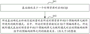
s41, the base station receives CQI corresponding to at least one time frequency resource;
s42, the base station determines a forming mode used by forming I pre-coding units in the time-frequency resource when the terminal channel is measured, wherein the time-frequency resource is divided into I pre-coding units, the forming mode represents the mapping relation between the I pre-coding units in the time-frequency resource and the pre-coding matrix in the pre-coding matrix group corresponding to the forming mode, and I is an integer larger than 1.
In a possible implementation manner, the number of the forming modes is N, and at least one item of information in precoding matrices included in a precoding matrix group corresponding to each forming mode is predetermined or notified by a semi-static signaling or a dynamic signaling after being determined by the base station; or a set corresponding relation exists between the at least one item of information and system parameters except the at least one item of information;
the number I of precoding units in at least one time frequency resource is predetermined or is notified by a semi-static signaling or a dynamic signaling after being determined by the base station; or a set corresponding relation exists between the number I of the precoding units in the time-frequency resource and system parameters except the number of the precoding units.
In a possible implementation manner, the receiving, by the base station, a CQI corresponding to at least one time-frequency resource further includes:
the base station receives index information of a forming mode used for forming I pre-coding units in the time-frequency resource when representing terminal channel measurement;
the method for the base station to determine the forming mode used by forming I pre-coding units in the time-frequency resource when the terminal channel is measured comprises the following steps: and the base station determines a forming mode used by forming I pre-coding units in the time-frequency resource when the terminal channel is measured according to the index information.
In a possible implementation manner, the receiving, by the base station, a CQI corresponding to at least one time-frequency resource further includes: the base station receives index information of a first precoding matrix;
the method for the base station to determine the forming mode used by forming I pre-coding units in the time-frequency resource when the terminal channel is measured comprises the following steps: and the base station determines a forming mode used for forming I pre-coding units in the time-frequency resource during the measurement of a terminal channel according to the received index information of the first pre-coding matrix.
After S42, the method further includes, according to any of the above embodiments:
the base station selects one forming mode from N forming modes;
and the base station uses different precoding matrixes in a precoding matrix group corresponding to the forming mode to form downlink data transmitted on I precoding units in at least one time-frequency resource according to the forming mode.
Optionally, the shaping, performed by the base station according to the shaping mode, of the downlink data transmitted on the I precoding units in the at least one time-frequency resource by using different precoding matrices in the precoding matrix group corresponding to the shaping mode includes:
the base station uses different precoding matrixes in a precoding matrix group corresponding to the forming mode to form data transmitted on I precoding units included in the time-frequency resource in a time domain; or
The base station uses different precoding matrixes in a precoding matrix group corresponding to the forming mode to form data transmitted on I precoding units included in the time-frequency resource on a frequency domain; or
The base station uses different pre-coding matrixes in a pre-coding matrix group corresponding to the shaping mode to shape data transmitted on I pre-coding units included in the time-frequency resource according to the sequence of a time domain and a frequency domain; or
And the base station uses different precoding matrixes in a precoding matrix group corresponding to the shaping mode to shape the data transmitted on the I precoding units included in the time-frequency resource according to the sequence of a frequency domain and a time domain.
Optionally, the precoding matrix in the precoding matrix group corresponding to the forming mode is obtained through function operation according to a first precoding matrix in a first codebook and a second precoding matrix in a second codebook;
the base station uses different precoding matrixes in a precoding matrix group corresponding to the forming mode to form downlink data transmitted on I precoding units in at least one time-frequency resource according to the forming mode, and the forming comprises the following steps:
the base station uses the same first precoding matrix and different second precoding matrices to respectively shape data transmitted on I precoding units included in the time-frequency resource; or
And the base station uses different first precoding matrixes and different second precoding matrixes to respectively shape the data transmitted on the I precoding units included in the time-frequency resource.
Optionally, the method further includes:
and the base station informs the shaping mode selected by the base station through a downlink signaling.
Specifically, if there is only one beamforming mode, that is, N is 1, the base station uses a beamforming mode that is the same as the beamforming mode used for CQI feedback corresponding to the time-frequency resource to perform beamforming on data transmitted on I precoding units included in the time-frequency resource;
if a plurality of forming modes exist, that is, N >1, the base station may select one forming mode from the N forming modes according to the CQI corresponding to the time-frequency resource, and by integrating information such as antenna configuration and moving speed of the terminal, the forming mode used for the feedback of the selected forming mode and the CQI corresponding to the time-frequency resource may be the same or different.
Optionally, the base station may notify, through downlink signaling, indication information for indicating the beamforming mode selected by the base station for data transmission.
For example, the base station uses 1bit signaling to notify whether a forming mode used by the CQI feedback corresponding to the time-frequency resource is used to form data, 1 represents that the eNB uses the forming mode used by the CQI feedback corresponding to the time-frequency resource to form data, and 0 represents that the eNB does not use the forming mode used by the CQI feedback corresponding to the time-frequency resource to form data.
For another example, the base station notifies indication information indicating the beamforming mode selected by the base station for data transmission through log2(N) bits signaling.
The above method process flow may be implemented by a software program, which may be stored in a storage medium, and when the stored software program is called, the above method steps are performed.
Based on the same inventive concept, an embodiment of the present invention further provides a channel state information feedback apparatus, as shown in fig. 5, the apparatus includes:
a forming module 51, configured to form, according to a determined forming mode, on precoding units in at least one time-frequency resource, using different precoding matrices in a precoding matrix group corresponding to the forming mode, where the time-frequency resource is divided into I precoding units, the forming mode corresponds to one precoding matrix group, the forming mode represents a mapping relationship between the I precoding units in the time-frequency resource and the precoding matrices in the precoding matrix group corresponding to the forming mode, and I is an integer greater than 1;
a measuring module 52, configured to perform channel measurement on the shaped time-frequency resource to obtain a channel quality indicator CQI corresponding to the time-frequency resource;
and a feedback module 53, configured to feedback the CQI corresponding to the time-frequency resource.
In a possible implementation manner, if the number N of the beamforming modes is greater than 1, the feedback module is further configured to: and feeding back the index information of the forming mode.
In a possible implementation manner, the number of the forming modes is N, and at least one item of information in a precoding matrix included in a precoding matrix group corresponding to each forming mode is predetermined or acquired through semi-static signaling or dynamic signaling; or a set corresponding relation exists between the at least one item of information and system parameters except the at least one item of information;
the number I of the precoding units in at least one time frequency resource is predetermined or acquired through semi-static signaling or dynamic signaling; or a set corresponding relation exists between the number I of the precoding units in the time-frequency resource and system parameters except the number of the precoding units.
In a possible implementation manner, the forming mode indicates that forming is performed on I precoding units in at least one time-frequency resource by using different precoding matrices in a precoding matrix group corresponding to the forming mode in a time domain; or
The indication of the forming mode is in a frequency domain, and different precoding matrixes in a precoding matrix group corresponding to the forming mode are used for forming on the I precoding units; or
The indication of the forming mode is according to the sequence of time domain first and frequency domain second, different precoding matrixes in a precoding matrix group corresponding to the forming mode are used for forming on the I precoding units; or
And the indication of the forming mode is used for forming on the I precoding units by using different precoding matrixes in a precoding matrix group corresponding to the forming mode according to the sequence of a frequency domain and a time domain.
In a possible implementation manner, the precoding matrix in the precoding matrix group corresponding to the forming mode is obtained through function operation according to a first precoding matrix in a first codebook and a second precoding matrix in a second codebook;
the forming mode indication uses the same first precoding matrix and different second precoding matrices to form on the I precoding units respectively; or
The forming mode indicates that different first precoding matrixes and different second precoding matrixes are used for forming on the I precoding units respectively.
In a possible implementation manner, if the forming mode indicates that the same first precoding matrix and a different second precoding matrix are used for forming on the I precoding units respectively,
the shaping module is specifically configured to: for each first precoding matrix in the first codebook, shaping on the I precoding units respectively by using the first precoding matrix and a different second precoding matrix;
the measurement module is specifically configured to: for each first precoding matrix in the first codebook, performing channel measurement on the shaped time-frequency resource to determine M CQIs corresponding to the time-frequency resource, wherein M is the number of the first precoding matrices in the first codebook; selecting one CQI from the M CQIs to determine the CQI corresponding to the time frequency resource;
the feedback module is further configured to: and feeding back index information of the first precoding matrix corresponding to the selected CQI.
Based on the same inventive concept, an embodiment of the present invention further provides a channel state information receiving apparatus, as shown in fig. 6, the apparatus includes:
a receiving module 61, configured to receive a channel quality indicator CQI corresponding to at least one time-frequency resource;
a determining module 62, configured to determine a forming mode used for forming I precoding units in the time-frequency resource during terminal channel measurement, where the time-frequency resource is divided into I precoding units, the forming mode corresponds to a precoding matrix group, the forming mode represents a mapping relationship between the I precoding units in the time-frequency resource and precoding matrices in the precoding matrix group corresponding to the forming mode, and I is an integer greater than 1.
In a possible implementation manner, the number of the forming modes is N, and at least one item of information in the precoding matrix included in the precoding matrix group corresponding to each forming mode is predetermined or determined by the determining module and notified through a semi-static signaling or a dynamic signaling; or a set corresponding relation exists between the at least one item of information and system parameters except the at least one item of information;
the number I of the precoding units in at least one time frequency resource is predetermined or determined by the determining module and is informed through semi-static signaling or dynamic signaling; or a set corresponding relation exists between the number I of the precoding units in the time-frequency resource and system parameters except the number of the precoding units.
In a possible implementation manner, the receiving module is further configured to: receiving index information of a forming mode used for forming I pre-coding units in the time-frequency resource when a terminal channel is measured;
the determining module is specifically configured to: and determining a forming mode used by forming I pre-coding units in the time-frequency resource during the measurement of the terminal channel according to the index information.
In a possible implementation manner, the forming mode indicates that forming is performed on I precoding units in at least one time-frequency resource by using different precoding matrices in a precoding matrix group corresponding to the forming mode in a time domain; or
The indication of the forming mode is in a frequency domain, and different precoding matrixes in a precoding matrix group corresponding to the forming mode are used for forming on the I precoding units; or
The indication of the forming mode is according to the sequence of time domain first and frequency domain second, different precoding matrixes in a precoding matrix group corresponding to the forming mode are used for forming on the I precoding units; or
And the indication of the forming mode is used for forming on the I precoding units by using different precoding matrixes in a precoding matrix group corresponding to the forming mode according to the sequence of a frequency domain and a time domain.
In a possible implementation manner, the forming mode indicates that the same first precoding matrix and different second precoding matrices are used for forming on the I precoding units respectively; or
The forming mode indicates that different first precoding matrixes and different second precoding matrixes are used for forming on the I precoding units respectively.
In a possible implementation manner, the receiving module is further configured to: receiving index information of a first precoding matrix;
the determining module is specifically configured to: and determining a forming mode used for forming I pre-coding units in the time-frequency resource during the measurement of the terminal channel according to the received index information of the first pre-coding matrix.
Based on the same inventive concept, an embodiment of the present invention further provides a terminal, and the same contents in this embodiment as those in the above channel state information feedback method please refer to the related description in the embodiment shown in fig. 1, which is not described herein again. As shown in fig. 7, the terminal includes: a transceiver 71, and at least one processor 72 connected to the transceiver 71, wherein:
a processor 72 for reading the program in the memory 73 and executing the following processes:
according to the determined forming mode, forming on precoding units in at least one time-frequency resource by using different precoding matrixes in a precoding matrix group corresponding to the forming mode, wherein the time-frequency resource is divided into I precoding units, the forming mode corresponds to one precoding matrix group, the forming mode represents the mapping relation between the I precoding units in the time-frequency resource and the precoding matrixes in the precoding matrix group corresponding to the forming mode, and I is an integer larger than 1; performing channel measurement on the shaped time-frequency resource to obtain a Channel Quality Indication (CQI) corresponding to the time-frequency resource; controlling the transceiver to feed back the CQI corresponding to the time-frequency resource;
a transceiver 71 for receiving and transmitting data under the control of a processor 72.
Wherein in fig. 7 the bus architecture may include any number of interconnected buses and bridges, with one or more processors represented by processor 72 and various circuits of memory represented by memory 73 being linked together. The bus architecture may also link together various other circuits such as peripherals, voltage regulators, power management circuits, and the like, which are well known in the art, and therefore, will not be described any further herein. The bus interface provides an interface. The transceiver 71 may be a number of elements including a transmitter and a receiver that provide a means for communicating with various other apparatus over a transmission medium. The user interface 74 may also be an interface capable of interfacing with a desired device for different user devices, including but not limited to a keypad, display, speaker, microphone, joystick, etc.
The processor 72 is responsible for managing the bus architecture and general processing, and the memory 73 may store data used by the processor 72 in performing operations.
In a possible implementation manner, if the number N of the beamforming modes is greater than 1, the processor reads the program in the memory and further executes: and feeding back the index information of the forming mode.
In a possible implementation manner, if the forming mode indicates that the same first precoding matrix and a different second precoding matrix are used for forming on the I precoding units respectively,
the processor reads the program in the memory, and specifically executes: for each first precoding matrix in the first codebook, shaping on the I precoding units respectively by using the first precoding matrix and a different second precoding matrix; for each first precoding matrix in the first codebook, performing channel measurement on the shaped time-frequency resource to determine M CQIs corresponding to the time-frequency resource, wherein M is the number of the first precoding matrices in the first codebook; selecting one CQI from the M CQIs to determine the CQI corresponding to the time frequency resource; and controlling the transceiver to feed back the index information of the first precoding matrix corresponding to the selected CQI.
Based on the same inventive concept, an embodiment of the present invention further provides a base station, and the same contents in this embodiment as those in the above-mentioned channel state information receiving method please refer to the related description in the embodiment shown in fig. 4, which is not described herein again. As shown in fig. 8, the base station includes: a transceiver 81, and at least one processor 82 coupled to the transceiver 81, wherein:
a processor 82 for reading the program in the memory 83, and executing the following processes:
receiving a Channel Quality Indicator (CQI) corresponding to at least one time-frequency resource through the transceiver; determining a forming mode used by forming I pre-coding units in the time-frequency resource during terminal channel measurement, wherein the time-frequency resource is divided into I pre-coding units, the forming mode corresponds to a pre-coding matrix group, the forming mode represents a mapping relation between the I pre-coding units in the time-frequency resource and pre-coding matrixes in the pre-coding matrix group corresponding to the forming mode, and I is an integer greater than 1;
a transceiver 81 for receiving and transmitting data under the control of a processor 82.
Wherein in fig. 8 the bus architecture may include any number of interconnected buses and bridges, with one or more processors represented by processor 82 and various circuits of memory represented by memory 83 being linked together. The bus architecture may also link together various other circuits such as peripherals, voltage regulators, power management circuits, and the like, which are well known in the art, and therefore, will not be described any further herein. The bus interface provides an interface. The transceiver 81 may be a number of elements including a transmitter and a receiver providing a means for communicating with various other apparatus over a transmission medium.
The processor 82 is responsible for managing the bus architecture and general processing, and the memory 83 may store data used by the processor 82 in performing operations.
In a possible implementation manner, the number of the forming modes is N, and at least one item of information in the precoding matrix included in the precoding matrix group corresponding to each forming mode is predetermined or determined by the processor and notified through a semi-static signaling or a dynamic signaling; or a set corresponding relation exists between the at least one item of information and system parameters except the at least one item of information;
the number I of precoding units in at least one time frequency resource is predetermined or is notified by the processor through semi-static signaling or dynamic signaling; or a set corresponding relation exists between the number I of the precoding units in the time-frequency resource and system parameters except the number of the precoding units.
In a possible implementation manner, the processor reads a program in the memory, and specifically executes:
receiving index information of a forming mode used for forming I pre-coding units in the time-frequency resource when a terminal channel is measured through the transceiver;
and determining a forming mode used by forming I pre-coding units in the time-frequency resource during the measurement of the terminal channel according to the index information.
In a possible implementation manner, the processor reads a program in the memory, and specifically executes:
receiving, by the transceiver, index information of a first precoding matrix;
and determining a forming mode used for forming I pre-coding units in the time-frequency resource during the measurement of the terminal channel according to the received index information of the first pre-coding matrix.
As will be appreciated by one skilled in the art, embodiments of the present invention may be provided as a method, system, or computer program product. Accordingly, the present invention may take the form of an entirely hardware embodiment, an entirely software embodiment or an embodiment combining software and hardware aspects. Furthermore, the present invention may take the form of a computer program product embodied on one or more computer-usable storage media (including, but not limited to, disk storage, CD-ROM, optical storage, and the like) having computer-usable program code embodied therein.
The present invention is described with reference to flowchart illustrations and/or block diagrams of methods, apparatus (systems), and computer program products according to embodiments of the invention. It will be understood that each flow and/or block of the flow diagrams and/or block diagrams, and combinations of flows and/or blocks in the flow diagrams and/or block diagrams, can be implemented by computer program instructions. These computer program instructions may be provided to a processor of a general purpose computer, special purpose computer, embedded processor, or other programmable data processing apparatus to produce a machine, such that the instructions, which execute via the processor of the computer or other programmable data processing apparatus, create means for implementing the functions specified in the flowchart flow or flows and/or block diagram block or blocks.
These computer program instructions may also be stored in a computer-readable memory that can direct a computer or other programmable data processing apparatus to function in a particular manner, such that the instructions stored in the computer-readable memory produce an article of manufacture including instruction means which implement the function specified in the flowchart flow or flows and/or block diagram block or blocks.
These computer program instructions may also be loaded onto a computer or other programmable data processing apparatus to cause a series of operational steps to be performed on the computer or other programmable apparatus to produce a computer implemented process such that the instructions which execute on the computer or other programmable apparatus provide steps for implementing the functions specified in the flowchart flow or flows and/or block diagram block or blocks.
While preferred embodiments of the present invention have been described, additional variations and modifications in those embodiments may occur to those skilled in the art once they learn of the basic inventive concepts. Therefore, it is intended that the appended claims be interpreted as including preferred embodiments and all such alterations and modifications as fall within the scope of the invention.
It will be apparent to those skilled in the art that various changes and modifications may be made in the present invention without departing from the spirit and scope of the invention. Thus, if such modifications and variations of the present invention fall within the scope of the claims of the present invention and their equivalents, the present invention is also intended to include such modifications and variations.