CN107307904B - Perfusion balloon catheter with flexible circuit electrode assembly - Google Patents
Perfusion balloon catheter with flexible circuit electrode assembly Download PDFInfo
- Publication number
- CN107307904B CN107307904B CN201710294648.8A CN201710294648A CN107307904B CN 107307904 B CN107307904 B CN 107307904B CN 201710294648 A CN201710294648 A CN 201710294648A CN 107307904 B CN107307904 B CN 107307904B
- Authority
- CN
- China
- Prior art keywords
- electrode
- contact
- balloon
- fingers
- electrophysiology catheter
- Prior art date
- Legal status (The legal status is an assumption and is not a legal conclusion. Google has not performed a legal analysis and makes no representation as to the accuracy of the status listed.)
- Active
Links
- 230000010412 perfusion Effects 0.000 title abstract description 14
- 239000000758 substrate Substances 0.000 claims abstract description 47
- 239000012528 membrane Substances 0.000 claims description 38
- 230000007831 electrophysiology Effects 0.000 claims description 23
- 238000002001 electrophysiology Methods 0.000 claims description 23
- PCHJSUWPFVWCPO-UHFFFAOYSA-N gold Chemical compound [Au] PCHJSUWPFVWCPO-UHFFFAOYSA-N 0.000 claims description 17
- 229910052737 gold Inorganic materials 0.000 claims description 17
- 239000010931 gold Substances 0.000 claims description 17
- 238000001802 infusion Methods 0.000 claims description 14
- 238000000034 method Methods 0.000 abstract description 25
- 210000003492 pulmonary vein Anatomy 0.000 abstract description 15
- 230000001225 therapeutic effect Effects 0.000 abstract description 3
- 230000008878 coupling Effects 0.000 abstract description 2
- 238000010168 coupling process Methods 0.000 abstract description 2
- 238000005859 coupling reaction Methods 0.000 abstract description 2
- 238000002679 ablation Methods 0.000 description 42
- 210000001519 tissue Anatomy 0.000 description 18
- RYGMFSIKBFXOCR-UHFFFAOYSA-N Copper Chemical compound [Cu] RYGMFSIKBFXOCR-UHFFFAOYSA-N 0.000 description 13
- 230000002093 peripheral effect Effects 0.000 description 9
- 229910052802 copper Inorganic materials 0.000 description 7
- 239000010949 copper Substances 0.000 description 7
- 230000006870 function Effects 0.000 description 7
- 239000012530 fluid Substances 0.000 description 6
- 230000003902 lesion Effects 0.000 description 6
- 229920002120 photoresistant polymer Polymers 0.000 description 6
- 229910001006 Constantan Inorganic materials 0.000 description 5
- 229910052751 metal Inorganic materials 0.000 description 5
- 239000002184 metal Substances 0.000 description 5
- 229920000139 polyethylene terephthalate Polymers 0.000 description 5
- 239000005020 polyethylene terephthalate Substances 0.000 description 5
- 239000000523 sample Substances 0.000 description 5
- 239000004642 Polyimide Substances 0.000 description 4
- 206010003119 arrhythmia Diseases 0.000 description 4
- 238000010276 construction Methods 0.000 description 4
- 229920001721 polyimide Polymers 0.000 description 4
- 239000000853 adhesive Substances 0.000 description 3
- 230000001070 adhesive effect Effects 0.000 description 3
- 230000006793 arrhythmia Effects 0.000 description 3
- 230000015572 biosynthetic process Effects 0.000 description 3
- 238000009529 body temperature measurement Methods 0.000 description 3
- 230000000747 cardiac effect Effects 0.000 description 3
- 239000004020 conductor Substances 0.000 description 3
- 238000005755 formation reaction Methods 0.000 description 3
- 210000005003 heart tissue Anatomy 0.000 description 3
- 239000003550 marker Substances 0.000 description 3
- 239000000463 material Substances 0.000 description 3
- 229910000679 solder Inorganic materials 0.000 description 3
- 238000004544 sputter deposition Methods 0.000 description 3
- 206010003130 Arrhythmia supraventricular Diseases 0.000 description 2
- 229920000106 Liquid crystal polymer Polymers 0.000 description 2
- 239000004977 Liquid-crystal polymers (LCPs) Substances 0.000 description 2
- KDLHZDBZIXYQEI-UHFFFAOYSA-N Palladium Chemical compound [Pd] KDLHZDBZIXYQEI-UHFFFAOYSA-N 0.000 description 2
- BQCADISMDOOEFD-UHFFFAOYSA-N Silver Chemical compound [Ag] BQCADISMDOOEFD-UHFFFAOYSA-N 0.000 description 2
- 210000003484 anatomy Anatomy 0.000 description 2
- 230000000712 assembly Effects 0.000 description 2
- 238000000429 assembly Methods 0.000 description 2
- 239000000560 biocompatible material Substances 0.000 description 2
- 238000003486 chemical etching Methods 0.000 description 2
- 238000005553 drilling Methods 0.000 description 2
- 230000007717 exclusion Effects 0.000 description 2
- 238000002594 fluoroscopy Methods 0.000 description 2
- 210000002837 heart atrium Anatomy 0.000 description 2
- 210000005246 left atrium Anatomy 0.000 description 2
- 238000004519 manufacturing process Methods 0.000 description 2
- 230000000873 masking effect Effects 0.000 description 2
- 238000005259 measurement Methods 0.000 description 2
- 238000002844 melting Methods 0.000 description 2
- 230000008018 melting Effects 0.000 description 2
- 210000004165 myocardium Anatomy 0.000 description 2
- 238000007747 plating Methods 0.000 description 2
- 229910052709 silver Inorganic materials 0.000 description 2
- 239000004332 silver Substances 0.000 description 2
- 238000005476 soldering Methods 0.000 description 2
- 229920001187 thermosetting polymer Polymers 0.000 description 2
- WFKWXMTUELFFGS-UHFFFAOYSA-N tungsten Chemical compound [W] WFKWXMTUELFFGS-UHFFFAOYSA-N 0.000 description 2
- 229910052721 tungsten Inorganic materials 0.000 description 2
- 239000010937 tungsten Substances 0.000 description 2
- 206010003658 Atrial Fibrillation Diseases 0.000 description 1
- 239000004593 Epoxy Substances 0.000 description 1
- 239000004696 Poly ether ether ketone Substances 0.000 description 1
- FAPWRFPIFSIZLT-UHFFFAOYSA-M Sodium chloride Chemical compound [Na+].[Cl-] FAPWRFPIFSIZLT-UHFFFAOYSA-M 0.000 description 1
- RTAQQCXQSZGOHL-UHFFFAOYSA-N Titanium Chemical compound [Ti] RTAQQCXQSZGOHL-UHFFFAOYSA-N 0.000 description 1
- 230000004075 alteration Effects 0.000 description 1
- 238000004873 anchoring Methods 0.000 description 1
- JUPQTSLXMOCDHR-UHFFFAOYSA-N benzene-1,4-diol;bis(4-fluorophenyl)methanone Chemical compound OC1=CC=C(O)C=C1.C1=CC(F)=CC=C1C(=O)C1=CC=C(F)C=C1 JUPQTSLXMOCDHR-UHFFFAOYSA-N 0.000 description 1
- 239000012620 biological material Substances 0.000 description 1
- 238000013153 catheter ablation Methods 0.000 description 1
- 239000012141 concentrate Substances 0.000 description 1
- 238000000354 decomposition reaction Methods 0.000 description 1
- 238000001514 detection method Methods 0.000 description 1
- 229910003460 diamond Inorganic materials 0.000 description 1
- 239000010432 diamond Substances 0.000 description 1
- 238000007599 discharging Methods 0.000 description 1
- 229920002457 flexible plastic Polymers 0.000 description 1
- 239000011888 foil Substances 0.000 description 1
- 230000017525 heat dissipation Effects 0.000 description 1
- 238000002513 implantation Methods 0.000 description 1
- 238000002347 injection Methods 0.000 description 1
- 239000007924 injection Substances 0.000 description 1
- 230000002262 irrigation Effects 0.000 description 1
- 238000003973 irrigation Methods 0.000 description 1
- 238000002955 isolation Methods 0.000 description 1
- 238000003475 lamination Methods 0.000 description 1
- 230000014759 maintenance of location Effects 0.000 description 1
- 239000000203 mixture Substances 0.000 description 1
- 230000002107 myocardial effect Effects 0.000 description 1
- 229910001000 nickel titanium Inorganic materials 0.000 description 1
- HLXZNVUGXRDIFK-UHFFFAOYSA-N nickel titanium Chemical compound [Ti].[Ti].[Ti].[Ti].[Ti].[Ti].[Ti].[Ti].[Ti].[Ti].[Ti].[Ni].[Ni].[Ni].[Ni].[Ni].[Ni].[Ni].[Ni].[Ni].[Ni].[Ni].[Ni].[Ni].[Ni] HLXZNVUGXRDIFK-UHFFFAOYSA-N 0.000 description 1
- 230000003287 optical effect Effects 0.000 description 1
- 229910052763 palladium Inorganic materials 0.000 description 1
- 230000037361 pathway Effects 0.000 description 1
- 230000000149 penetrating effect Effects 0.000 description 1
- 230000035515 penetration Effects 0.000 description 1
- 239000004033 plastic Substances 0.000 description 1
- 229920000728 polyester Polymers 0.000 description 1
- 229920006267 polyester film Polymers 0.000 description 1
- 229920002530 polyetherether ketone Polymers 0.000 description 1
- -1 polyethylene terephthalate Polymers 0.000 description 1
- 229920000642 polymer Polymers 0.000 description 1
- 239000004814 polyurethane Substances 0.000 description 1
- 229920002635 polyurethane Polymers 0.000 description 1
- 230000008569 process Effects 0.000 description 1
- 238000007674 radiofrequency ablation Methods 0.000 description 1
- 239000004065 semiconductor Substances 0.000 description 1
- 238000003860 storage Methods 0.000 description 1
- 229910052719 titanium Inorganic materials 0.000 description 1
- 239000010936 titanium Substances 0.000 description 1
- 230000000007 visual effect Effects 0.000 description 1
- 239000011800 void material Substances 0.000 description 1
- XLYOFNOQVPJJNP-UHFFFAOYSA-N water Substances O XLYOFNOQVPJJNP-UHFFFAOYSA-N 0.000 description 1
Images


Classifications
-
- A—HUMAN NECESSITIES
- A61—MEDICAL OR VETERINARY SCIENCE; HYGIENE
- A61B—DIAGNOSIS; SURGERY; IDENTIFICATION
- A61B18/00—Surgical instruments, devices or methods for transferring non-mechanical forms of energy to or from the body
- A61B18/04—Surgical instruments, devices or methods for transferring non-mechanical forms of energy to or from the body by heating
- A61B18/12—Surgical instruments, devices or methods for transferring non-mechanical forms of energy to or from the body by heating by passing a current through the tissue to be heated, e.g. high-frequency current
- A61B18/14—Probes or electrodes therefor
- A61B18/1492—Probes or electrodes therefor having a flexible, catheter-like structure, e.g. for heart ablation
-
- A—HUMAN NECESSITIES
- A61—MEDICAL OR VETERINARY SCIENCE; HYGIENE
- A61B—DIAGNOSIS; SURGERY; IDENTIFICATION
- A61B18/00—Surgical instruments, devices or methods for transferring non-mechanical forms of energy to or from the body
- A61B18/04—Surgical instruments, devices or methods for transferring non-mechanical forms of energy to or from the body by heating
- A61B18/12—Surgical instruments, devices or methods for transferring non-mechanical forms of energy to or from the body by heating by passing a current through the tissue to be heated, e.g. high-frequency current
- A61B18/14—Probes or electrodes therefor
-
- A—HUMAN NECESSITIES
- A61—MEDICAL OR VETERINARY SCIENCE; HYGIENE
- A61B—DIAGNOSIS; SURGERY; IDENTIFICATION
- A61B5/00—Measuring for diagnostic purposes; Identification of persons
- A61B5/68—Arrangements of detecting, measuring or recording means, e.g. sensors, in relation to patient
- A61B5/6846—Arrangements of detecting, measuring or recording means, e.g. sensors, in relation to patient specially adapted to be brought in contact with an internal body part, i.e. invasive
- A61B5/6847—Arrangements of detecting, measuring or recording means, e.g. sensors, in relation to patient specially adapted to be brought in contact with an internal body part, i.e. invasive mounted on an invasive device
- A61B5/6852—Catheters
- A61B5/6853—Catheters with a balloon
-
- A—HUMAN NECESSITIES
- A61—MEDICAL OR VETERINARY SCIENCE; HYGIENE
- A61B—DIAGNOSIS; SURGERY; IDENTIFICATION
- A61B5/00—Measuring for diagnostic purposes; Identification of persons
- A61B5/24—Detecting, measuring or recording bioelectric or biomagnetic signals of the body or parts thereof
- A61B5/25—Bioelectric electrodes therefor
- A61B5/279—Bioelectric electrodes therefor specially adapted for particular uses
- A61B5/28—Bioelectric electrodes therefor specially adapted for particular uses for electrocardiography [ECG]
- A61B5/283—Invasive
- A61B5/287—Holders for multiple electrodes, e.g. electrode catheters for electrophysiological study [EPS]
-
- A—HUMAN NECESSITIES
- A61—MEDICAL OR VETERINARY SCIENCE; HYGIENE
- A61B—DIAGNOSIS; SURGERY; IDENTIFICATION
- A61B5/00—Measuring for diagnostic purposes; Identification of persons
- A61B5/68—Arrangements of detecting, measuring or recording means, e.g. sensors, in relation to patient
- A61B5/6846—Arrangements of detecting, measuring or recording means, e.g. sensors, in relation to patient specially adapted to be brought in contact with an internal body part, i.e. invasive
- A61B5/6847—Arrangements of detecting, measuring or recording means, e.g. sensors, in relation to patient specially adapted to be brought in contact with an internal body part, i.e. invasive mounted on an invasive device
- A61B5/6852—Catheters
- A61B5/6857—Catheters with a distal pigtail shape
-
- A—HUMAN NECESSITIES
- A61—MEDICAL OR VETERINARY SCIENCE; HYGIENE
- A61M—DEVICES FOR INTRODUCING MEDIA INTO, OR ONTO, THE BODY; DEVICES FOR TRANSDUCING BODY MEDIA OR FOR TAKING MEDIA FROM THE BODY; DEVICES FOR PRODUCING OR ENDING SLEEP OR STUPOR
- A61M25/00—Catheters; Hollow probes
- A61M25/10—Balloon catheters
-
- B—PERFORMING OPERATIONS; TRANSPORTING
- B29—WORKING OF PLASTICS; WORKING OF SUBSTANCES IN A PLASTIC STATE IN GENERAL
- B29C—SHAPING OR JOINING OF PLASTICS; SHAPING OF MATERIAL IN A PLASTIC STATE, NOT OTHERWISE PROVIDED FOR; AFTER-TREATMENT OF THE SHAPED PRODUCTS, e.g. REPAIRING
- B29C65/00—Joining or sealing of preformed parts, e.g. welding of plastics materials; Apparatus therefor
- B29C65/02—Joining or sealing of preformed parts, e.g. welding of plastics materials; Apparatus therefor by heating, with or without pressure
- B29C65/14—Joining or sealing of preformed parts, e.g. welding of plastics materials; Apparatus therefor by heating, with or without pressure using wave energy, i.e. electromagnetic radiation, or particle radiation
- B29C65/16—Laser beams
-
- B—PERFORMING OPERATIONS; TRANSPORTING
- B29—WORKING OF PLASTICS; WORKING OF SUBSTANCES IN A PLASTIC STATE IN GENERAL
- B29C—SHAPING OR JOINING OF PLASTICS; SHAPING OF MATERIAL IN A PLASTIC STATE, NOT OTHERWISE PROVIDED FOR; AFTER-TREATMENT OF THE SHAPED PRODUCTS, e.g. REPAIRING
- B29C65/00—Joining or sealing of preformed parts, e.g. welding of plastics materials; Apparatus therefor
- B29C65/48—Joining or sealing of preformed parts, e.g. welding of plastics materials; Apparatus therefor using adhesives, i.e. using supplementary joining material; solvent bonding
-
- G—PHYSICS
- G03—PHOTOGRAPHY; CINEMATOGRAPHY; ANALOGOUS TECHNIQUES USING WAVES OTHER THAN OPTICAL WAVES; ELECTROGRAPHY; HOLOGRAPHY
- G03F—PHOTOMECHANICAL PRODUCTION OF TEXTURED OR PATTERNED SURFACES, e.g. FOR PRINTING, FOR PROCESSING OF SEMICONDUCTOR DEVICES; MATERIALS THEREFOR; ORIGINALS THEREFOR; APPARATUS SPECIALLY ADAPTED THEREFOR
- G03F7/00—Photomechanical, e.g. photolithographic, production of textured or patterned surfaces, e.g. printing surfaces; Materials therefor, e.g. comprising photoresists; Apparatus specially adapted therefor
- G03F7/16—Coating processes; Apparatus therefor
-
- H—ELECTRICITY
- H05—ELECTRIC TECHNIQUES NOT OTHERWISE PROVIDED FOR
- H05K—PRINTED CIRCUITS; CASINGS OR CONSTRUCTIONAL DETAILS OF ELECTRIC APPARATUS; MANUFACTURE OF ASSEMBLAGES OF ELECTRICAL COMPONENTS
- H05K3/00—Apparatus or processes for manufacturing printed circuits
- H05K3/40—Forming printed elements for providing electric connections to or between printed circuits
- H05K3/4038—Through-connections; Vertical interconnect access [VIA] connections
-
- H—ELECTRICITY
- H05—ELECTRIC TECHNIQUES NOT OTHERWISE PROVIDED FOR
- H05K—PRINTED CIRCUITS; CASINGS OR CONSTRUCTIONAL DETAILS OF ELECTRIC APPARATUS; MANUFACTURE OF ASSEMBLAGES OF ELECTRICAL COMPONENTS
- H05K3/00—Apparatus or processes for manufacturing printed circuits
- H05K3/46—Manufacturing multilayer circuits
- H05K3/4644—Manufacturing multilayer circuits by building the multilayer layer by layer, i.e. build-up multilayer circuits
-
- A—HUMAN NECESSITIES
- A61—MEDICAL OR VETERINARY SCIENCE; HYGIENE
- A61B—DIAGNOSIS; SURGERY; IDENTIFICATION
- A61B17/00—Surgical instruments, devices or methods, e.g. tourniquets
- A61B2017/00526—Methods of manufacturing
-
- A—HUMAN NECESSITIES
- A61—MEDICAL OR VETERINARY SCIENCE; HYGIENE
- A61B—DIAGNOSIS; SURGERY; IDENTIFICATION
- A61B18/00—Surgical instruments, devices or methods for transferring non-mechanical forms of energy to or from the body
- A61B2018/00005—Cooling or heating of the probe or tissue immediately surrounding the probe
- A61B2018/00011—Cooling or heating of the probe or tissue immediately surrounding the probe with fluids
- A61B2018/00029—Cooling or heating of the probe or tissue immediately surrounding the probe with fluids open
-
- A—HUMAN NECESSITIES
- A61—MEDICAL OR VETERINARY SCIENCE; HYGIENE
- A61B—DIAGNOSIS; SURGERY; IDENTIFICATION
- A61B18/00—Surgical instruments, devices or methods for transferring non-mechanical forms of energy to or from the body
- A61B2018/00053—Mechanical features of the instrument of device
- A61B2018/00059—Material properties
- A61B2018/00071—Electrical conductivity
- A61B2018/00083—Electrical conductivity low, i.e. electrically insulating
-
- A—HUMAN NECESSITIES
- A61—MEDICAL OR VETERINARY SCIENCE; HYGIENE
- A61B—DIAGNOSIS; SURGERY; IDENTIFICATION
- A61B18/00—Surgical instruments, devices or methods for transferring non-mechanical forms of energy to or from the body
- A61B2018/00053—Mechanical features of the instrument of device
- A61B2018/0016—Energy applicators arranged in a two- or three dimensional array
-
- A—HUMAN NECESSITIES
- A61—MEDICAL OR VETERINARY SCIENCE; HYGIENE
- A61B—DIAGNOSIS; SURGERY; IDENTIFICATION
- A61B18/00—Surgical instruments, devices or methods for transferring non-mechanical forms of energy to or from the body
- A61B2018/00053—Mechanical features of the instrument of device
- A61B2018/00214—Expandable means emitting energy, e.g. by elements carried thereon
- A61B2018/0022—Balloons
- A61B2018/0025—Multiple balloons
- A61B2018/00261—Multiple balloons arranged in a line
-
- A—HUMAN NECESSITIES
- A61—MEDICAL OR VETERINARY SCIENCE; HYGIENE
- A61B—DIAGNOSIS; SURGERY; IDENTIFICATION
- A61B18/00—Surgical instruments, devices or methods for transferring non-mechanical forms of energy to or from the body
- A61B2018/00315—Surgical instruments, devices or methods for transferring non-mechanical forms of energy to or from the body for treatment of particular body parts
- A61B2018/00345—Vascular system
- A61B2018/00351—Heart
- A61B2018/00357—Endocardium
-
- A—HUMAN NECESSITIES
- A61—MEDICAL OR VETERINARY SCIENCE; HYGIENE
- A61B—DIAGNOSIS; SURGERY; IDENTIFICATION
- A61B18/00—Surgical instruments, devices or methods for transferring non-mechanical forms of energy to or from the body
- A61B2018/00315—Surgical instruments, devices or methods for transferring non-mechanical forms of energy to or from the body for treatment of particular body parts
- A61B2018/00345—Vascular system
- A61B2018/00351—Heart
- A61B2018/00375—Ostium, e.g. ostium of pulmonary vein or artery
-
- A—HUMAN NECESSITIES
- A61—MEDICAL OR VETERINARY SCIENCE; HYGIENE
- A61B—DIAGNOSIS; SURGERY; IDENTIFICATION
- A61B18/00—Surgical instruments, devices or methods for transferring non-mechanical forms of energy to or from the body
- A61B2018/00571—Surgical instruments, devices or methods for transferring non-mechanical forms of energy to or from the body for achieving a particular surgical effect
- A61B2018/00577—Ablation
-
- A—HUMAN NECESSITIES
- A61—MEDICAL OR VETERINARY SCIENCE; HYGIENE
- A61B—DIAGNOSIS; SURGERY; IDENTIFICATION
- A61B18/00—Surgical instruments, devices or methods for transferring non-mechanical forms of energy to or from the body
- A61B2018/00636—Sensing and controlling the application of energy
- A61B2018/00642—Sensing and controlling the application of energy with feedback, i.e. closed loop control
-
- A—HUMAN NECESSITIES
- A61—MEDICAL OR VETERINARY SCIENCE; HYGIENE
- A61B—DIAGNOSIS; SURGERY; IDENTIFICATION
- A61B18/00—Surgical instruments, devices or methods for transferring non-mechanical forms of energy to or from the body
- A61B2018/00636—Sensing and controlling the application of energy
- A61B2018/00696—Controlled or regulated parameters
- A61B2018/00702—Power or energy
-
- A—HUMAN NECESSITIES
- A61—MEDICAL OR VETERINARY SCIENCE; HYGIENE
- A61B—DIAGNOSIS; SURGERY; IDENTIFICATION
- A61B18/00—Surgical instruments, devices or methods for transferring non-mechanical forms of energy to or from the body
- A61B2018/00636—Sensing and controlling the application of energy
- A61B2018/00773—Sensed parameters
- A61B2018/00791—Temperature
- A61B2018/00821—Temperature measured by a thermocouple
-
- A—HUMAN NECESSITIES
- A61—MEDICAL OR VETERINARY SCIENCE; HYGIENE
- A61B—DIAGNOSIS; SURGERY; IDENTIFICATION
- A61B18/00—Surgical instruments, devices or methods for transferring non-mechanical forms of energy to or from the body
- A61B2018/00636—Sensing and controlling the application of energy
- A61B2018/00773—Sensed parameters
- A61B2018/00839—Bioelectrical parameters, e.g. ECG, EEG
-
- A—HUMAN NECESSITIES
- A61—MEDICAL OR VETERINARY SCIENCE; HYGIENE
- A61B—DIAGNOSIS; SURGERY; IDENTIFICATION
- A61B18/00—Surgical instruments, devices or methods for transferring non-mechanical forms of energy to or from the body
- A61B2018/00636—Sensing and controlling the application of energy
- A61B2018/00773—Sensed parameters
- A61B2018/00892—Voltage
-
- A—HUMAN NECESSITIES
- A61—MEDICAL OR VETERINARY SCIENCE; HYGIENE
- A61B—DIAGNOSIS; SURGERY; IDENTIFICATION
- A61B18/00—Surgical instruments, devices or methods for transferring non-mechanical forms of energy to or from the body
- A61B18/04—Surgical instruments, devices or methods for transferring non-mechanical forms of energy to or from the body by heating
- A61B18/12—Surgical instruments, devices or methods for transferring non-mechanical forms of energy to or from the body by heating by passing a current through the tissue to be heated, e.g. high-frequency current
- A61B18/14—Probes or electrodes therefor
- A61B2018/1405—Electrodes having a specific shape
- A61B2018/1407—Loop
-
- A—HUMAN NECESSITIES
- A61—MEDICAL OR VETERINARY SCIENCE; HYGIENE
- A61B—DIAGNOSIS; SURGERY; IDENTIFICATION
- A61B18/00—Surgical instruments, devices or methods for transferring non-mechanical forms of energy to or from the body
- A61B18/04—Surgical instruments, devices or methods for transferring non-mechanical forms of energy to or from the body by heating
- A61B18/12—Surgical instruments, devices or methods for transferring non-mechanical forms of energy to or from the body by heating by passing a current through the tissue to be heated, e.g. high-frequency current
- A61B18/14—Probes or electrodes therefor
- A61B2018/1405—Electrodes having a specific shape
- A61B2018/1417—Ball
-
- A—HUMAN NECESSITIES
- A61—MEDICAL OR VETERINARY SCIENCE; HYGIENE
- A61B—DIAGNOSIS; SURGERY; IDENTIFICATION
- A61B18/00—Surgical instruments, devices or methods for transferring non-mechanical forms of energy to or from the body
- A61B18/04—Surgical instruments, devices or methods for transferring non-mechanical forms of energy to or from the body by heating
- A61B18/12—Surgical instruments, devices or methods for transferring non-mechanical forms of energy to or from the body by heating by passing a current through the tissue to be heated, e.g. high-frequency current
- A61B18/14—Probes or electrodes therefor
- A61B2018/1465—Deformable electrodes
-
- A—HUMAN NECESSITIES
- A61—MEDICAL OR VETERINARY SCIENCE; HYGIENE
- A61B—DIAGNOSIS; SURGERY; IDENTIFICATION
- A61B18/00—Surgical instruments, devices or methods for transferring non-mechanical forms of energy to or from the body
- A61B18/04—Surgical instruments, devices or methods for transferring non-mechanical forms of energy to or from the body by heating
- A61B18/12—Surgical instruments, devices or methods for transferring non-mechanical forms of energy to or from the body by heating by passing a current through the tissue to be heated, e.g. high-frequency current
- A61B18/14—Probes or electrodes therefor
- A61B2018/1497—Electrodes covering only part of the probe circumference
-
- A—HUMAN NECESSITIES
- A61—MEDICAL OR VETERINARY SCIENCE; HYGIENE
- A61B—DIAGNOSIS; SURGERY; IDENTIFICATION
- A61B2218/00—Details of surgical instruments, devices or methods for transferring non-mechanical forms of energy to or from the body
- A61B2218/001—Details of surgical instruments, devices or methods for transferring non-mechanical forms of energy to or from the body having means for irrigation and/or aspiration of substances to and/or from the surgical site
- A61B2218/002—Irrigation
-
- A—HUMAN NECESSITIES
- A61—MEDICAL OR VETERINARY SCIENCE; HYGIENE
- A61B—DIAGNOSIS; SURGERY; IDENTIFICATION
- A61B2562/00—Details of sensors; Constructional details of sensor housings or probes; Accessories for sensors
- A61B2562/12—Manufacturing methods specially adapted for producing sensors for in-vivo measurements
- A61B2562/125—Manufacturing methods specially adapted for producing sensors for in-vivo measurements characterised by the manufacture of electrodes
-
- A—HUMAN NECESSITIES
- A61—MEDICAL OR VETERINARY SCIENCE; HYGIENE
- A61B—DIAGNOSIS; SURGERY; IDENTIFICATION
- A61B2562/00—Details of sensors; Constructional details of sensor housings or probes; Accessories for sensors
- A61B2562/16—Details of sensor housings or probes; Details of structural supports for sensors
- A61B2562/164—Details of sensor housings or probes; Details of structural supports for sensors the sensor is mounted in or on a conformable substrate or carrier
-
- A—HUMAN NECESSITIES
- A61—MEDICAL OR VETERINARY SCIENCE; HYGIENE
- A61M—DEVICES FOR INTRODUCING MEDIA INTO, OR ONTO, THE BODY; DEVICES FOR TRANSDUCING BODY MEDIA OR FOR TAKING MEDIA FROM THE BODY; DEVICES FOR PRODUCING OR ENDING SLEEP OR STUPOR
- A61M25/00—Catheters; Hollow probes
- A61M25/10—Balloon catheters
- A61M2025/1043—Balloon catheters with special features or adapted for special applications
- A61M2025/1086—Balloon catheters with special features or adapted for special applications having a special balloon surface topography, e.g. pores, protuberances, spikes or grooves
-
- B—PERFORMING OPERATIONS; TRANSPORTING
- B29—WORKING OF PLASTICS; WORKING OF SUBSTANCES IN A PLASTIC STATE IN GENERAL
- B29L—INDEXING SCHEME ASSOCIATED WITH SUBCLASS B29C, RELATING TO PARTICULAR ARTICLES
- B29L2031/00—Other particular articles
- B29L2031/753—Medical equipment; Accessories therefor
- B29L2031/7542—Catheters
Landscapes
- Health & Medical Sciences (AREA)
- Life Sciences & Earth Sciences (AREA)
- Engineering & Computer Science (AREA)
- Surgery (AREA)
- Physics & Mathematics (AREA)
- Heart & Thoracic Surgery (AREA)
- Veterinary Medicine (AREA)
- Animal Behavior & Ethology (AREA)
- Public Health (AREA)
- Biomedical Technology (AREA)
- General Health & Medical Sciences (AREA)
- Medical Informatics (AREA)
- Molecular Biology (AREA)
- Biophysics (AREA)
- Pathology (AREA)
- Cardiology (AREA)
- Plasma & Fusion (AREA)
- Nuclear Medicine, Radiotherapy & Molecular Imaging (AREA)
- Otolaryngology (AREA)
- Microelectronics & Electronic Packaging (AREA)
- Manufacturing & Machinery (AREA)
- Mechanical Engineering (AREA)
- General Physics & Mathematics (AREA)
- Electromagnetism (AREA)
- Toxicology (AREA)
- Optics & Photonics (AREA)
- Child & Adolescent Psychology (AREA)
- Pulmonology (AREA)
- Anesthesiology (AREA)
- Hematology (AREA)
- Physiology (AREA)
- Measurement And Recording Of Electrical Phenomena And Electrical Characteristics Of The Living Body (AREA)
- Surgical Instruments (AREA)
- Media Introduction/Drainage Providing Device (AREA)
- Electrotherapy Devices (AREA)
Abstract
The invention provides a perfusion balloon catheter with a flexible circuit electrode assembly. A perfusion balloon catheter for use in the ostium of a pulmonary vein includes a flexible circuit electrode assembly adapted to contact the ostium perimeter when the balloon is inflated. The balloon catheter is suitable for diagnostic and therapeutic applications and procedures, and may be used with lasso catheters or focal catheters. The flexible circuit electrode assembly includes: a substrate; a contact electrode on an outer surface of the base, the contact electrode having a "fishbone" configuration comprising a longitudinally elongated portion and a plurality of transverse fingers; a wiring electrode on an inner surface of the substrate; and a conductive via extending through the substrate and electrically coupling the contact electrode and the wiring electrode. A microelectrode having an expulsion area is strategically positioned relative to the electrode. The electrode may also be divided into electrode portions.
Description
Cross reference to related patent applications
This application is a continuation-in-part application OF U.S. patent application 15/141,751 entitled "METHOD OF CONSTRUCTING IRRIGATED BALLOON CATHETER" filed 2016, 4, 28, and claiming priority and interest from that application, which is incorporated herein by reference in its entirety. This application is also a continuation-in-part application entitled "BALLOON CATHETER AND RELATED IMPEDANCE-BASED METHODS FOR DETECTING OCCLUSION" filed on 2016, 6/2, and claiming priority and interest from that application, which is incorporated herein by reference in its entirety.
Technical Field
The present invention relates to medical devices. More particularly, the present invention relates to improvements in cardiac catheterization, including Electrophysiology (EP) catheters, particularly EP catheters used to map and/or ablate ostial and tubular regions in the heart.
Background
When a region of cardiac tissue abnormally conducts electrical signals to adjacent tissue, an arrhythmia, such as atrial fibrillation, occurs, disrupting the normal cardiac cycle and causing an arrhythmia.
Protocols for treating cardiac arrhythmias include surgically disrupting the source of the signal causing the arrhythmia, as well as disrupting the conduction pathway for such signals. By applying energy through a catheter to selectively ablate cardiac tissue, it is sometimes possible to stop or alter the propagation of unwanted electrical signals from one part of the heart to another. The ablation method breaks the unwanted electrical path by forming a non-conductive ablation lesion.
Peripheral lesions at or near the ostium of the pulmonary vein have been created to treat atrial arrhythmias. Us patents 6,012,457 and 6,024,740 to Lesh disclose radially expandable ablation devices that include radio frequency electrodes. To establish a peripheral conduction block, it has been proposed to use the device to deliver radiofrequency energy to the pulmonary veins, thereby electrically isolating the pulmonary veins from the left atrium.
U.S. patent 6,814,733 to Schwartz et al, which is commonly assigned and incorporated herein by reference, describes a catheter introduction device having a radially expandable helical coil as a radio frequency transmitter. In one application, the emitter is introduced percutaneously and is advanced to the ostium of the pulmonary vein at intervals. In order to bring the emitter into circumferential contact with the inner wall of the pulmonary vein, the emitter is radially expanded, which may be accomplished by inflating an anchoring balloon around which the emitter is encapsulated. The coil is powered by a radio frequency generator and a peripheral lesion is created in the myocardial cuff of the pulmonary vein, which effectively blocks electrical propagation between the pulmonary vein and the left atrium.
Another example in U.S. patent 7,340,307 to Maguire et al proposes a tissue ablation system and method for treating atrial arrhythmias by ablating a peripheral region of tissue at a location where a pulmonary vein extends from an atrium. The system includes a peripheral ablation member having ablation elements, and includes a delivery assembly for delivering the ablation member to the location. The peripheral ablation member is generally adjustable between different configurations to allow both delivery of the ablation member into the atrium and ablation coupling between the ablation element and the peripheral region of tissue through the delivery sheath.
More recently, inflatable catheter electrode assemblies have been constructed with flexible circuits, which provide many small electrodes on the outer surface of the inflatable electrode assembly. An example of a catheter Balloon structure is described in U.S. patent publication 2016/0175041 entitled "Balloon for implantation electrode Balloon vehicle," which is incorporated herein by reference in its entirety.
Flexible circuits or flexible electronics involve techniques for assembling electronic circuits by mounting the electronic devices on flexible plastic substrates such as polyimide, Liquid Crystal Polymer (LCP), PEEK, or transparent conductive polyester film (PET). Further, the flexible circuit may be a screen printed silver circuit on polyester. Flexible Printed Circuits (FPCs) are made using photolithographic techniques. An alternative method of making a flexible foil circuit or Flexible Flat Cable (FFC) is to laminate a very thin (0.07mm) copper tape between two layers of PET. These PET layers are typically 0.05mm thick, coated with a thermosetting adhesive, and will be activated during the lamination process. A single-sided flexible circuit has a single conductor layer made of metal or conductive (metal-filled) polymer on a flexible dielectric film. The component termination features are accessible from only one side. Holes may be formed in the base film to allow component leads to pass through for interconnection (typically by soldering).
However, due to differences in the human anatomy, the size of ostia and tubular regions in the heart vary. As a result, conventional balloons or inflatable catheters may not simultaneously satisfy the flexibility to accommodate different shapes and sizes and the structural support sufficient for effective circumferential contact with tissue. In particular, ablation electrodes capable of providing greater surface contact may lack sufficient flexibility. Furthermore, the fine wires (such as the wires of the electrode leads and/or thermocouple wires) and their solder joints need to be supported and protected from breakage and damage during assembly and use in the patient. In addition, because the balloon configuration is radially symmetric and the plurality of electrode elements surround the balloon configuration, it is also very difficult to orient the balloon electrode assembly under fluoroscopy.
Accordingly, there is a need for a balloon or catheter having an inflatable member that not only can contact a larger area of tissue, but also maintains sufficient flexibility to accommodate different anatomies and tight space constraints at the ostium and pulmonary veins. There is also a need for a balloon catheter that carries an electrode assembly that can be manufactured with flexible circuits and that can accommodate the ostium and the pulmonary vein. There is also a need for a balloon catheter that can perform multiple functions, including diagnostic and therapeutic functions, such as ablation, pacing, steering, temperature sensing, potential sensing, and impedance sensing, and that is adaptable for use with other catheters, including lasso catheters or lesion catheters.
Disclosure of Invention
The present invention relates to a catheter with a perfused inflatable balloon suitable for use in the ostium of a pulmonary vein. The balloon includes a flexible circuit electrode assembly adapted to contact the circumference of the orifice when the balloon is inflated. Balloon catheters are well suited for diagnostic and therapeutic applications and procedures, and may be used with lasso or focal catheters.
In some embodiments, an electrophysiology catheter suitable for use in a nozzle comprises: a balloon having a membrane, the balloon having a distal end and a proximal end defining a longitudinal axis; and a contact electrode supported on the membrane, the contact electrode configured for contact with the nosepiece, the contact electrode having a "fishbone" configuration comprising a longitudinally elongated portion and a plurality of transverse fingers.
In some more detailed embodiments, the transverse fingers are of different lengths, and the contact electrodes have longer fingers and shorter fingers, the longer fingers being located near the equatorial region of the balloon. Further, the plurality of fingers may include a distal finger, a proximal finger, and fingers therebetween, wherein each of the fingers therebetween has a shorter adjacent finger. The width of the elongate portion may be greater than the width of each finger. The plurality of fingers may be substantially evenly spaced along the elongate portion. The plurality of fingers may have a substantially uniform width.
In some more detailed embodiments, the contact electrode comprises gold. The contact electrode may include a seed layer under gold. The balloon may have a plurality of contact electrodes substantially uniformly radially distributed on the balloon membrane.
In some embodiments, an electrophysiology catheter includes a balloon having a membrane and a flexible circuit electrode assembly on the membrane. The flexible circuit has: the semiconductor device includes a substrate with a first surface and a second surface, a contact electrode on the first surface, a wiring electrode on the second surface, and a conductive via (conductive via) extending through the substrate and adapted to be conductively connected to the contact electrode and the wiring electrode.
In some more detailed embodiments, the substrate includes a first infusion orifice and the membrane includes a second infusion orifice aligned with the first infusion orifice. Further, the contact electrode may include a drain region surrounding the first filling hole, and the wiring electrode may include a drain region surrounding the first filling hole. The wired electrode may have an elongated body longitudinally aligned with the elongated portion. The routing electrode may include a pad, wherein the flexible circuit electrode assembly includes a wire pair conductively connected to the pad.
In still further detailed embodiments, the flexible circuit electrode includes a "fishbone" contact microelectrode, a "spine" wiring microelectrode, and a conductive via configured to conductively couple the contact microelectrode and the wiring electrode. The microelectrode is strategically positioned relative to the electrode proximate to and proximal to the electrode, but physically and electrically isolated from the electrode. The flexible circuit electrode includes at least one exclusion zone configured to physically and electrically isolate the micro-electrode from the contact electrode and the routing electrode. The microelectrodes may be configured as "islands" that are entirely circumferentially surrounded by the contact or wiring electrodes and are physically and electrically isolated from the contact or wiring electrodes by the drain regions.
In some embodiments, the flexible circuit electrode includes a proximal tail. A conductive wire configured for conductive connection to the contact electrode and/or the routing electrode may extend between the proximal tail and the balloon membrane toward the shaft of the balloon catheter. In some embodiments, the conductive wires may extend through-holes (vias) formed in the balloon membrane into the interior of the balloon.
In some embodiments, the contact electrode and the wiring electrode may be divided into a plurality of portions, wherein the respective contact electrode portion and the respective wiring electrode portion are conductively coupled through a conductive via. Each of the pair of conductively connected contact electrode portions and routing electrode portions has a conductive wire. Each of the split electrode portions may surround a corresponding microelectrode which is physically and electrically isolated by the discharge region.
In some embodiments, a conductive wire configured to conductively connect with the electrodes and microelectrodes may be included in the ribbon cable. The ribbon cable may enter the interior of the balloon through a through hole formed in the balloon membrane. Alternatively, the ribbon cable may extend between the tail of the flexible circuit electrode assembly and the balloon membrane toward the proximal end of the balloon prior to entering the shaft proximal to the balloon.
In some embodiments, the flexible circuit electrode assembly includes a thermocouple for use with a contact microelectrode, wherein the thermocouple has a wire pair embedded in the flexible circuit substrate and connected to each other by a conductive via (connecting via) conductively coupled to the contact electrode. Advantageously, the thermocouple is configured to measure the temperature of the tissue in contact with the contact microelectrode as it undergoes ablation by an adjacent ablation contact electrode. Alternatively, the thermocouple may simultaneously sense the electrode potential signal from the tissue and the temperature of the tissue while the tissue is not undergoing ablation.
In some embodiments, the flexible circuit electrode assembly comprises first and second pads conductively coupled to first and second lines of the thermocouple, the pads advantageously positioned away from the microelectrode, for example in the region of the proximal tail, wherein the electrical potential between the first and second pads comprises a signal representative of the temperature sensed by the thermocouple 400 at the location of the microelectrode 401. Moreover, each of the pads thus electrically coupled can also obtain an electrode potential formed on its corresponding micro-electrode 401 through its conductive via.
In some embodiments, the pads coupled to the contact electrodes, the microelectrodes, and the thermocouples for ablating, sensing electrode potentials and temperatures may be grouped into a set, with the flex circuit electrode assembly including multiple sets of pads all located away from the microelectrodes.
In some embodiments, the balloon catheter is configured for use with a second catheter that extends through the shaft of the balloon catheter. The second catheter may comprise a lasso catheter or a linear focal catheter.
Drawings
These and other features and advantages of the present invention will be better understood by reference to the following detailed description when considered in connection with the accompanying drawings. It should be understood that selected structures and features are not shown in some of the figures to provide a better view of the remaining structures and features.
Figure 1 is a schematic illustration of an invasive medical procedure according to an embodiment of the present invention.
Fig. 2 is a top view of a balloon catheter of the present invention in its inflated state and in use with a lasso catheter, according to an embodiment of the present invention.
Fig. 3 is a perspective view of the balloon catheter of fig. 2 along with a lasso catheter.
Fig. 4 is a side view of a balloon deployed in the pulmonary vein and its orifice region.
Figure 5 is a top plan view of a plurality of flexible circuit electrode assemblies according to an embodiment of the present invention.
Fig. 6 is a perspective view of a flexible circuit electrode assembly partially lifted from a balloon according to an embodiment of the present invention.
Fig. 7, 8A, 9A, 10, 11A, 12A, 13A are exploded perspective views of a flexible circuit electrode assembly at various stages of construction according to embodiments of the present invention.
Fig. 8B, 9B, 11B, 12B, 13B, 14 are side cross-sectional views of a flexible circuit electrode assembly at various stages of construction according to embodiments of the present invention.
Fig. 15A is an exploded perspective view of a flexible circuit electrode assembly according to another embodiment of the present invention, with portions of the contact electrodes separated to show the layers thereof.
FIG. 15B is a detailed top plan view of the wiring micro-electrode separated from the wiring electrode by the discharge region according to the embodiment of the present invention.
FIG. 15C is a detailed top plan view of a contact microelectrode separated from a contact electrode by an expulsion area, according to an embodiment of the present invention.
FIG. 16A is a detailed top plan view of an "island" contact microelectrode positioned in a contact electrode, according to embodiments of the present invention.
FIG. 16B is a detailed top plan view of an "island" contact microelectrode positioned in a contact electrode, according to an embodiment of the present invention.
Fig. 17 is a top plan view of a flex circuit electrode assembly with split contact electrodes according to an embodiment of the present invention.
Fig. 18A is a side cross-sectional view of an embedded thermocouple according to an embodiment of the present invention.
Fig. 18B is a top cross-sectional view of an embedded padgroup according to an embodiment of the invention.
Detailed Description
SUMMARY
The use of cardiac tissue ablation to correct a malfunctioning heart is a well-known procedure for achieving such correction. Generally, to successfully ablate, cardiac electrode potentials need to be measured at various locations of the myocardium. Furthermore, temperature measurements during ablation provide data enabling the efficacy of the ablation to be measured. Typically, for ablation protocols, electrode potentials and temperatures are measured before, during, and after the actual ablation.
In contrast to prior art systems that use two or more separate instructions (e.g., one for electrode potential and temperature measurement, and another for ablation), embodiments of the present invention facilitate both measurements and also enable ablation using a single balloon catheter using radio frequency electromagnetic energy. The catheter has a lumen, and an inflatable balloon is deployed through the catheter lumen (the balloon travels through the lumen in a collapsed, uninflated configuration, and the balloon inflates as it exits the lumen). The balloon has an outer wall or membrane and has a distal end and a proximal end defining a longitudinal axis of the extended lumen.
The multilayer flexible metal structure is attached to the outer wall or membrane of the balloon. The structure includes a plurality of electrode sets arranged circumferentially about the longitudinal axis, wherein each electrode set includes a plurality of ablation electrodes arranged generally longitudinally.
Each set of electrodes may further include at least one microelectrode physically and electrically isolated from the ablation electrodes in the set.
Each electrode set may further include at least one thermocouple.
In some embodiments, each electrode set has a microelectrode and a thermocouple formed at the same location.
The use of a single balloon catheter simplifies the cardiac ablation procedure by having the three functions of performing ablation, electrode potential measurement, and temperature measurement.
Description of the System
In the following description, like elements in the drawings are identified by like numerals, and the like elements may be distinguished by attaching letters after the identification numerals as needed.
Figure 1 is a schematic illustration of an invasive medical procedure using apparatus 12, in accordance with an embodiment of the present invention. The procedure is performed by a medical professional 14 and, by way of example, it is assumed that the procedure in the following description includes ablation of a portion of the myocardium 16 of the heart of a human patient 18. However, it should be understood that embodiments of the present invention are not only applicable to this particular procedure, but may also include essentially any procedure on biological tissue or non-biological material.
To perform ablation, the medical professional 14 inserts the probe 20 into a sheath 21 that has been previously positioned in a body lumen of a patient. The sheath 21 is positioned such that the distal end 22 of the probe 20 enters the patient's heart. A balloon catheter 24, described in detail below with reference to fig. 2, is deployed through the lumen 23 of the stylet 20 and exits from the distal end of the stylet 20.
As shown in FIG. 1, the device 12 is controlled by a system processor 46, which is located in the device's operating console 15. Console 15 includes controls 49 used by practitioner 14 to communicate with the processor. The processor 46 generally tracks the position and orientation of the distal end 22 of the probe 20 during the procedure using any method known in the art. For example, processor 46 may use a magnetic tracking method in which magnetic transmitters 25X, 25Y, and 25Z external to patient 18 generate signals in coils positioned in the distal end of probe 20. From Biosense Webster, Diamond Bar, Calif Such tracking methods are used.
Software for the processor 46 may be downloaded to the processor in electronic form, over a network, for example. Alternatively or in addition, the software may be provided on a non-transitory tangible medium such as an optical, magnetic, or electronic storage medium. The tracking of the distal end 22 is typically displayed on a three-dimensional representation 60 of the heart of the patient 18 on a screen 62.
To operate the device 12, the processor 46 communicates with a memory 50 having a plurality of modules used by the processor to operate the device. Accordingly, memory 50 includes a temperature module 52, an ablation module 54, and an Electrocardiogram (ECG) module 56, the functions of which are described below. Memory 50 typically includes other modules, such as a force module for measuring force on distal end 22, a tracking module for operating a tracking method used by processor 46, and a perfusion module that allows the processor to control perfusion provided for distal end 22. Such other modules are not shown in fig. 1 for simplicity. Modules also include hardware as well as software elements.
Fig. 3 is a schematic perspective view of balloon catheter 24 in its inflated configuration, according to an embodiment of the present invention. In the disclosed embodiment, in which the balloon catheter 24 is used to ablate the ostium 11 of a lumen, such as a pulmonary vein 13, as shown in fig. 4, the balloon catheter 24 is supported by a tubular shaft 70 having a proximal shaft portion 82 and a distal shaft end 88. The shaft 70 includes a hollow center tube 74 that allows a catheter to pass therethrough and past the distal shaft end 88. The catheter may be a linear focal catheter or lasso catheter 72, as shown. The lasso catheter 72 may be inserted into the pulmonary vein to properly position the balloon catheter 24 relative to the ostium prior to ostium ablation. The distal lasso portion of the catheter 72 is typically formed of a shape memory retention material such as nitinol. It should be understood that the balloon catheter 24 may also be used with a linear or focal catheter 99 (shown in phantom in fig. 3) in other locations of the PV or heart. The focal catheter 99 may include a force sensor at its distal tip. Suitable force transmitting distal TIPs are disclosed in us patent 8,357,152 entitled "CATHETER WITH PRESSURE SENSING" issued by Govari et al on 22.1.2013 and us patent application 2011/0130648 entitled "CATHETER WITH PRESSURE MEASURING TIP" filed on 30.11.2009 by Beeckler et al, the entire contents of which are incorporated herein by reference. Any catheter used with a balloon catheter may have features and functions including, for example, pressure sensing, ablation, diagnostics (e.g., steering and pacing).
The inflatable balloon 80 of the balloon catheter 24 is of a biocompatible material (e.g., made of a material such as polyethylene terephthalate (PET), polyurethane, or Plastic) or
 membrane 26. The shaft 70 and the distal shaft end 88 define the longitudinal axis 78 of the balloon 80. Balloon 80 is passed in a collapsed, uninflated configurationIs deployed by the lumen 23 of the probe 20 and may be inflated after exiting the distal end 22. Balloon 80 may be inflated and deflated by injection and expulsion of a fluid, such as a water saline solution, through shaft 70. The membrane 26 of the balloon 80 is formed with irrigation holes or apertures 27 (shown in fig. 6) through which fluid can be expelled from the interior of the balloon 80 to the exterior of the balloon to cool the tissue ablation site at the orifice. Although fig. 2 and 4 show the fluid exiting the balloon 80 as a jet, it should be understood that the fluid may exit the balloon at any desired flow rate and/or pressure, including the rate at which the fluid seeps from the balloon.
The membrane 26 supports and carries the combined electrodes and temperature sensing components constructed as a multi-layer flex circuit electrode assembly 84. The "flex circuit electrode assembly" 84 can have many different geometric configurations. In the illustrated embodiment, the flex circuit electrode assembly 84 has a plurality of radiating blades or strips 30, as best shown in fig. 5. The blades 30 are evenly distributed around the distal end 88 and the balloon 80. Each blade has a wider proximal portion that tapers to a narrower distal portion.
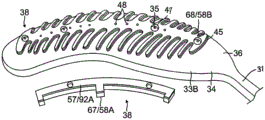
Referring to fig. 3 and 5, each blade 30 has a proximal tail 31P and a distal tail 31D. The proximal tail 31P is tucked under and secured to the catheter 24 by a proximal ring 28P mounted on a proximal shaft portion 82 of the shaft 70. The distal tail 31D is plugged below the catheter 24 by a distal ring (not shown) and secured to the catheter. Either or both of the tail portions 31D and 31P may be further covered by a respective hemispherical cover, such as the distal cover 28D. The one or more contact electrodes 33 on each blade make galvanic contact with the nozzle 11 during the ablation procedure, during which time current flows from the contact electrodes 33 to the nozzle 11, as shown in fig. 4.
For simplicity, only one of the blades 30 of the flex circuit electrode assembly 84 is described, as shown in FIG. 6, but it should be understood that the following description may apply to each blade of the assembly. The flexible circuit electrode assembly 84 includes a flexible and resilient sheet substrate 34 constructed of a suitable biocompatible material, such as polyimide. In some embodiments, the sheet form base 34 has a higher heat resistance (or higher melting temperature) than the balloon membrane 26. In some embodiments, substrate 34 is constructed of a thermoset material having a decomposition temperature that is about 100 ℃ or greater than the melting temperature of balloon membrane 26.
The substrate 34 is formed with one or more perfusion apertures or holes 35, the apertures or holes 35 being aligned with the perfusion holes 35 of the balloon member 26 such that fluid passing through the perfusion holes 35 can pass through the ablation sites on the nozzle.
The base 34 has a first or outer surface 36 facing away from the balloon membrane 26 and a second or inner surface 37 facing the balloon membrane 26. On its outer surface 36, the base 34 supports and carries a contact electrode 33 adapted to be in contact with the tissue of the orifice. On its inner surface 37, the substrate 34 supports and carries wiring electrodes 38. The contact electrodes 33 deliver RF energy to the nozzle during ablation and/or are connected to a thermocouple junction for temperature sensing of the nozzle. In the illustrated embodiment, the contact electrode 33 has a longitudinally elongated portion 40 and a plurality of thin, transverse, linear portions or fingers 41 extending generally perpendicularly from each side of the elongated portion 40 between the enlarged proximal and distal ends 42P, 42D and spaced generally uniformly therebetween. The elongated portion 40 has a greater width and each finger has a generally uniform smaller width. Thus, the configuration or trace of the contact electrode 33 resembles a "fishbone". In contrast to the area or "patch" ablation electrodes, the fingers 41 of the contact electrode 33 advantageously increase the circumferential or equatorial contact surface of the contact electrode 33 with the ostium, while the interstitial areas 43 between adjacent fingers 41 advantageously allow the balloon 80 to collapse inwardly and/or expand radially as needed at locations along its equator. In the embodiment shown, the fingers 41 have different lengths, some being longer and others being shorter. For example, the plurality of fingers includes a distal finger, a proximal finger, and fingers therebetween, wherein each of the fingers therebetween has a shorter adjacent finger. For example, each finger has a different length than its immediately distally and/or proximally adjacent neighboring fingers, such that the length of each finger generally follows the tapered configuration of each lobe 30. In the illustrated embodiment, there are 22 fingers extending across the elongated portion 40 (through each side), the longest finger being the third finger from the enlarged proximal end 42P. In some embodiments, contact electrode 33 includes gold 58B with a seed layer 45 between gold 58B and film 26 (see fig. 12A and 12B). The seed layer may include titanium, tungsten, palladium, silver, and/or combinations thereof.
One or more drain regions 47 are formed within the contact electrode 33, each surrounding a perfusion aperture 27 formed in the substrate 26. The drain region 47 is a purposefully formed void in the contact electrode 33, as described in further detail below, to avoid positional and functional damage to the contact electrode 33 when the infusion port 27 is received during construction of the electrode assembly 84.
The contact electrode 33 also has formed therein one or more conductive blind vias 48(blind vias), which are conductive or metal-containing formations that extend through-holes 55 in the substrate 34, as shown in fig. 8A, and are configured as cables that connect the contact electrode 33 on the outer surface 36 and the routing electrode 38 on the inner surface 37. It should be understood that in all relevant cases, "electrically conductive" is used herein interchangeably with "metal-containing".
In the illustrated embodiment, contact electrode 33 measures about 0.1 inch to 1.0 inch, preferably about 0.5 inch to 0.7 inch, and more preferably about 0.57 inch, longitudinally, and has four exhaust areas 47 and nine blind holes 48.
On the inner surface 37 of the substrate 34, a wiring electrode 38 is generally configured as an elongated body that is substantially similar in shape and size to the elongated portion 40 of the contact electrode 33. The wiring electrode 38 loosely resembles a "spine" and also acts as a spine in providing a predetermined degree of longitudinal stiffness to each of the leaves 30 of the electrode assembly 84. The wiring electrodes 38 are positioned such that each blind hole 48 is in electrically conductive contact with both the contact electrode 33 and the wiring electrode 38. In the embodiment shown, the two electrodes 33 and 38 are longitudinally aligned with the other electrodes, and all nine blind holes 48 are in conductive contact with the two electrodes 33 and 38. In some embodiments, the wiring electrode 38 has an inner portion of copper 57 and an outer portion of gold 58.
The wiring electrode 38 is also formed with an exhaust region 59 surrounding the perfusion hole 35 in the substrate 34. The wiring electrode 38 is also formed with a pad portion 61, at least one active pad portion 61A, and one or more inactive pad portions 61B may be present. The pad portions 61A and 61B are extensions of the side faces of the elongated body of the wiring electrode 38. In the exemplified embodiment, the active pad portion 61A is formed at about a mid-position along the elongated body, and a respective inactive pad portion 61B is provided at each of the enlarged distal end 42D and the enlarged proximal end 42P.
Wire pairs (e.g., constantan wire 51 and copper wire 53) are attached to the active pad portion 61A, for example, by soldering 63. Copper wire 53 provides a lead to wiring electrode 33 and copper wire 53 and constantan wire 51 provide a thermocouple with a joint at weld 63. The wire pair 51/53 passes through a via 29 formed in the film 26. It should be understood that in other embodiments, in the absence of through-hole 29, wire pair 51/53 may extend between membrane 26 and base 34 and also extend proximally between membrane 26 and proximal tail 31P until wire pair 51/53 enters tubular shaft 70 via another through-hole (not shown) formed in the tubular shaft sidewall closer to proximal ring 28.
The flex circuit electrode assembly 84, including the blade 30 and tails 31P and 31D, is attached to the balloon membrane 26 such that the outer surface 36 of the base 34 is exposed and the inner surface 37 of the base 34 is attached to the balloon membrane 26 with the wired electrode 38 and wire pair 51/53 sandwiched between the base 34 and the balloon membrane 26. Perfusion holes 35 in the base 34 are aligned with perfusion holes 27 on the balloon membrane 26. The drain region 59 in the wiring electrode 38 and the drain region 47 in the contact electrode 33 are concentrically aligned with each other and with the perfusion holes 27 and 35, as shown in fig. 14.
Construction method
The invention includes methods of constructing a flexible circuit electrode assembly and a balloon having the flexible circuit electrode assembly. In some embodiments, the method comprises the following steps 1-9. It should be understood that the steps need not be performed in the order shown, as desired or appropriate.


Steps 1-9 are discussed in detail below with reference to FIGS. 7-13, in conjunction with FIG. 6.
1)A flexible circuit 90 is provided having a flexible substrate 34 with a first or outer surface 36 generally defined by a first surface Conductive layer 91 is covered and second or inner surface 37 of the substrate is typically covered by a second conductive layer 92, as shown in FIG. 7. In some embodiments, substrate 34 is constructed of polyimide and first conductive layer 91 and second conductive layer 92 are copper.
2)The first conductive layer 91 is removed as shown in fig. 8A and 8B. In some embodiments, the first conductive layer 91 of copper is removed from the outer surface 36 of the substrate 34 by chemical etching to expose the outer surface of the substrate.
3)The wiring electrode 38 is formed in the second conductive layer 92 as shown in fig. 8A and 8B. Forming the wiring electrode 38 may include forming an elongated body having at least the drain region 59. Forming the wiring electrode 38 may include forming at least one active pad 61A. Forming routing electrode 38 may include forming at least one inactive pad 61B that can serve as a visually radiopaque marker. In some embodiments, forming the wiring electrode 38 includes: masking the configuration of the elongate body with one or more pads in a first portion 92A of the second conductive layer 92, while leaving unmasked second portion 92B and one or more drainage areas 59 in the first portion 92A; and removing unmasked one or more exclusion regions 59 and second conductive layer 92 in second portion 92B from inner surface 37 of substrate 34 by chemical etching.
4)One or more through-holes 55 are formed in the substrate 34 to provide one or more blind-holes 48 and to form one or more An infusion port 35, as shown in FIGS. 8A and 9A. In some embodiments, forming the through-hole 55 and/or the infusion hole 35 includes a peripheral trace contacting the electrode 33Laser drilling is performed through substrate 34 from a direction facing outer surface 36 at a location within line 66 (shown in phantom in fig. 10) to a depth through the entire thickness of substrate 34. In forming the through hole 55 for the blind via 48, laser drilling is generally performed without penetrating the wiring electrode 38.
5)An additional conductive layer 67 is applied to all exposed conductive surfaces on substrate 34 and wiring electrode 38, as shown 9A and 9B. In some embodiments, the substrate 34 formed with the routing electrodes 38 is immersed in a gold plating bath to form a gold layer 58A covering the exposed conductive surfaces of the elongated bodies of the routing electrodes 38 and the bottom surfaces 65 of any and all blind vias 48.
6) Contact electrodes 33 are formed on the exposed outer layer 36 of the substrate 34, as shown in fig. 10, 11A, 12A and 13 Display device. In some embodiments, forming the contact electrode 33 includes: (i) defining the first region 33A within a perimeter trace 66 (comprising the elongated body 40 and the fingers 41) of a fishbone configuration on the outer surface 36 of the substrate 34, as shown in fig. 10; (ii) applying photoresist 39 to the second region 33B outside the first region 33A on the outer layer 36 of the substrate 34, as shown in FIG. 11B; (iii) applying a seed layer 45 to the outer surface 36 of the substrate 34 in at least the first region 33A, as shown in fig. 11A and 11B; (iv) applying another additional conductive layer 68, such as gold 58B, on at least the seed layer 45, as shown in fig. 12A and 12B; and (v) removing the photoresist 39, along with any portions of the seed layer 45 and the conductive layer 68 on the photoresist, from the substrate 34, as shown in fig. 12A and 12B. In some embodiments, applying the photoresist 39 includes applying the photoresist 39 to one or more exhaust regions 47 in the elongated portion 40 of the contact electrode 33 surrounding the infusion hole 35 formed in the substrate 34. In some embodiments, applying the seed layer 45 includes sputtering the seed layer 45 inside the one or more blind holes 48. In some embodiments, applying conductive layer 68 includes sputtering conductive layer 68 inside one or more blind holes 48. In some embodiments, the blind via is formed with sloped or tapered sidewalls 69 (see fig. 12B) covered by seed layer 45 and conductive layer 68/58B.
7)At the baseAnother conductive layer 71 is applied on the bottom 34 over all exposed conductive surfaces, including the contact electrode 33 And wiring electrodes 38 as shown in FIGS. 13A and 13B. In some embodiments, substrate 34 including electrodes 33 and 38 is again immersed in a gold plating bath to form another layer of gold 58C covering the exposed conductive surfaces of electrodes 33 and 38 and all blind vias 48. In some embodiments, radiopaque markers 73 are applied or coated onto the gold layer 58C covering the wire electrode 38. For example, a mixture comprising tungsten and epoxy may be applied to the gold layer 58C on the wire electrode 38 as a radiopaque marker.
8)Preparing a flexible circuit electrode assembly 84 for attachment to balloon 80, as shown in FIG. 6. In the formation of flex circuit electrode assembly 84, steps 1-7 above form electrodes 33 and 38 on substrate 34, which can then be prepared for attachment to balloon membrane 26. In some embodiments, wire pair 51/53 is soldered to active pad 61A, where wire pair 51/53 serves as a thermocouple and copper wire 53 serves as a lead for delivering RF energy to wiring electrode 38, which in turn powers contact electrode 33. In some embodiments, peripheral region 34P of base 34 is formed with a plurality of perforations 75 (penetrations) configured to receive an adhesive for attaching electrode assembly 84 to balloon membrane 26.
9)Attaching the flex circuit electrode assembly 84 to the balloon membrane 26 as shown in FIG. 6. In some embodiments, wire pair 51/53 is fed through a through hole 29 formed in film 26 and an adhesive (not shown) is applied to substantially the entire inner surface 37 of substrate 34, including wiring electrodes 38, to adhere flex circuit electrode assembly 84 to film 26.
It is to be understood that the invention encompasses other embodiments having simpler steps and/or fewer steps than those described above. For example, forming a contact electrode in a "fishbone" configuration may include sputtering a seed layer and a second additional conductive layer directly onto the balloon membrane, thereby eliminating the use of a substrate and wiring electrode. Suitable wiring may be provided in the configurations described herein, and/or similar blind vias, full vias (i.e., through contact electrodes, substrates, wiring electrodes, contact microelectrodes, and/or wiring microelectrodes), conductive traces, and the like may be provided, as will be appreciated by one of ordinary skill in the art. Such a balloon catheter would still provide all of the advantages provided by a "fishbone" contact electrode, as described herein.
In other embodiments of the invention, the flexible circuit electrode assembly 184 as shown in FIG. 15A includes one or more contact microelectrodes 101 and wiring microelectrodes 102 physically and electrically isolated from the contact electrodes 133 and wiring electrodes 138, respectively. The contact micro-electrodes 101 and the wiring electrodes 102 aligned in pairs are electrically conductively connected to each other through the blind holes 148. At the same time as the formation of the one or more microelectrodes 101 and 102, the corresponding electrodes 133 and 138 are also formed in each of the aforementioned steps. In the illustrated embodiment, the microelectrodes 101 and 102 are positioned near the midpoint along the length of the electrodes 133 and 138 such that the microelectrodes 101 and 102 are proximate the equatorial region of the balloon 80, although it should be understood that they may be located in other positions relative to the electrodes 133 and 138. Microelectrodes 101 and 103 are configured to have impedance, electrical signal and/or temperature sensing independent of electrodes 133 and 138, and are thus physically and electrically isolated from contact electrode 133 and wiring electrode 138 by one or more respective drain regions 103 and 104, respectively.
To form the wiring micro-electrode 102, for example, a photoresist is applied to the outer surface 136 of the substrate 134 where the discharge region 103 is to be formed. In the illustrated embodiment, as shown in fig. 15B, the wiring microelectrode 102 is formed with a protrusion 107 that protrudes into a conformal recess 108 formed in the elongated body of the wiring electrode 138. The discharge region 104 spans between the protrusion 107 and the groove 108, adopting a conformal configuration between the wiring electrode 138 and the wiring microelectrodes 102.
For the contact microelectrodes 101, they are formed by appropriately masking the second conductive layer 192 (not shown) on the inner surface 137 of the substrate 134 according to the configuration of the contact microelectrodes 101. In the illustrated embodiment, as shown in fig. 15C, the protrusion 105 masks the contact microelectrode 101, protruding into the recess 106 formed in the elongated portion 140 of the contact electrode 133. The ejection area 103 spans between the protrusion 105 and the groove 106, adopting a conformal configuration between the contact electrode 133 and the contact microelectrode 101.
The protrusions 105 and 107 allow the microelectrodes 101 and 102 to be as close as possible to the contact electrode 133 and the wiring electrode 138, and thus as close as possible to the tissue contact site, while maintaining physical and electrical isolation.
As for the contact electrode 133, it is also possible to divide it into contact electrode portions 133A and 133B, as shown in fig. 17, corresponding to the divided wiring electrode portions 138A and 138B, in which the contact electrode portion 133A is conductively connected to the wiring electrode portion 138A through the blind hole 148A, and the contact electrode portion 133B is conductively connected to the wiring electrode portion 138B through the blind hole 148B.
It should be understood that microelectrodes 101 and 102 can also be formed as "islands" (of any suitable shape and size), each island being entirely surrounded by a drain region 106 and 107 formed in electrodes 133 and 138 (in an integral or separate electrode portion), respectively, as shown in FIGS. 16A, 16B and 17. A blind hole 148 may be formed in each contact microelectrode 101 to provide an electrically conductive connection to its wiring microelectrode 102. A full via 188 may be formed in each wiring microelectrode 102 as a conductive connection to its wire pair, which enables the microelectrodes 101 and 102 to be used for ablation, electrode potential, sensing, impedance detection and/or temperature sensing.
Fig. 18A shows a thermocouple 400 formed from a copper conductor or wire 476 connected to a constantan conductor or wire 477 by a conductive via 481. Lines 476 and 477 are formed as conductive lines embedded in substrate 424. The through-hole 481 is also connected to the contact micro-electrode 401 on the outer surface of the substrate. By connecting the thermocouple 400 to the micro-electrode 401, it is possible to measure the temperature of the tissue contacting the micro-electrode 401 while acquiring an electrode potential signal of the tissue. Alternatively, for example, in the case where contact electrode 433 is used for ablation, the temperature of the tissue in contact with micro-electrode 401 can be measured without acquiring an electrode potential signal of micro-electrode 401.
As shown in fig. 18B, the lines 476 and 477 exit from pads 463a and 463B, respectively, which are located in a region away from the micro-electrode 401, the proximal tail 31P, for example, near the distal end thereof. The potential between pads 463a and 463b includes a signal to temperature module 52 in console 15 (FIG. 1), and this module uses this signal to represent the temperature measured by thermocouple 400 at the location of microelectrode 401. Further, the pad 463a connected to the copper wire 476 and/or the pad 463b connected to the constantan wire 477 may also be used to take out an electrode potential formed on the micro-electrode 401 to which the pad is connected through the via 481. The ECG module 56 of console 15 (fig. 1) typically receives signals derived from pads 463a and/or 463b and analyzes the signals to derive electrode potentials at microelectrodes 401.
The solder pad 463c is connected to the contact electrode 433 by another wire embedded in the substrate 434, and the solder pad 463c may be used to transmit electromagnetic RF ablation energy generated by the ablation module 54 of the console 15 (fig. 1) to the contact electrode 433. As shown in fig. 18B, the pads 463c, 463a, and 463B may be divided into groups of three pads 463G (1) connected to the contact electrode 433, the micro-electrode 401, and the thermocouple 400. A set of three pads 463g (i) may be connected to a set of contact electrodes, micro-electrodes and thermocouples. It is noted that the location of at least pads 463a and 463b may advantageously be remote from the location where the temperature is measured, so that embedding of any bulk pieces in pads 463a and 463b at the location where tissue contact of microelectrode 401 occurs may be avoided.
As shown in fig. 15, an infusion hole 127 is formed in the balloon film 126, an infusion hole 135 is formed in the substrate 134, a discharge area 147 is formed in the contact electrode 133, and a discharge area 159 is formed in the wiring electrode 138.
In some embodiments, the substrate 34, 134 (e.g., polyimide) has a thickness of about 25.0 microns. The wiring electrodes 38, 138 include an inner layer of copper having a thickness of about 2.0 microns and an outer layer of gold having a thickness in the range of about 1.0 microns to 50 microns, preferably about 2.75 microns to 37 microns, with the thickness of the gold depending on the desired or suitable radiopacity. The contact electrodes 33, 133 include a seed layer having a thickness of about 0.01 to 0.05 microns and a gold outer layer having a thickness of about 1.0 micron. The balloon membranes 26, 126 may have an average thickness of about 25.0 microns, as it will be appreciated that the membranes may have a non-uniform thickness due to the manufacturing process.
In operation, wire pair 51/53 conducts RF energy provided by ablation module 54 of console 15 (fig. 1) through the control handle and catheter shaft to wiring electrode 38, which in turn powers contact electrode 33 through blind hole 48.
In some embodiments, where balloon 80 comprises a flex circuit electrode assembly having 10 blades (providing 10 contact electrodes), 10 functionally satisfactory lesions can be generated by simultaneously discharging 25W of RF power per contact electrode 33, i.e., a total of 250W in 10 seconds or less. By using high power to generate the lesions in a short period of time, the "pulsing" of the power is effectively utilized and heat dissipation from the ablation site is minimized. In other words, a short ablation time helps to concentrate the thermal energy at the site, while less energy is transferred out of the site.
In other embodiments, suitable power ranges for each contact electrode include between about 15W-25W for 10 seconds and 10W-20W for 60 seconds. In other embodiments, the power supplied to each contact electrode is 25W or more for 10 seconds or less.
The foregoing description has been presented with reference to presently preferred embodiments of the invention. Those skilled in the art to which the invention pertains will appreciate that alterations and changes in the described structure may be practiced without meaningfully departing from the principle, spirit and scope of this invention. Any feature or structure disclosed in one embodiment may be incorporated as needed or appropriate in place of or in addition to other features of any other embodiment. As will be appreciated by those of ordinary skill in the art, the drawings are not necessarily drawn to scale. Accordingly, the foregoing description should not be deemed to be merely related to the precise structures described and illustrated in the accompanying drawings, but rather should be deemed to be in accordance with and as support for the following claims, which are to have their fullest and fair scope.
Claims (18)
1. An electrophysiology catheter adapted for use with a nozzle, comprising:
a balloon having a membrane, the balloon having a distal end and a proximal end defining a longitudinal axis; and
a contact electrode supported on the membrane, the contact electrode configured for contact with the nosepiece, the contact electrode having a fishbone configuration including a longitudinally elongated portion and a plurality of transverse fingers,
wherein the contact electrodes have longer fingers and shorter fingers, the longer fingers being located near an equatorial region of the balloon.
2. The electrophysiology catheter of claim 1 wherein at least two of said lateral fingers have different lengths.
3. The electrophysiology catheter of claim 1 wherein the plurality of lateral fingers includes a distal finger, a proximal finger, and fingers therebetween, wherein each of the fingers therebetween has a shorter adjacent finger.
4. The electrophysiology catheter of claim 1 wherein a width of the elongated portion is greater than a width of each finger.
5. The electrophysiology catheter of claim 1 wherein said plurality of lateral fingers are substantially evenly spaced along said elongated portion.
6. The electrophysiology catheter of claim 1 wherein said plurality of lateral fingers have a substantially uniform width.
7. The electrophysiology catheter of claim 1 wherein said contact electrode comprises gold.
8. The electrophysiology catheter of claim 7 wherein said contact electrode comprises a seed layer under said gold.
9. The electrophysiology catheter of claim 1 further comprising a plurality of contact electrodes substantially uniformly radially distributed on the balloon membrane.
10. An electrophysiology catheter comprising:
a balloon having a membrane; and
a flexible circuit electrode assembly on the membrane, the flexible circuit electrode assembly having:
a substrate having a first surface and a second surface;
a contact electrode on the first surface, wherein the contact electrode has a fishbone configuration comprising a longitudinally elongated portion and a plurality of transverse fingers;
a wiring electrode on the second surface; and
a conductive via extending through the substrate and adapted to conductively connect the contact electrode and the wiring electrode,
wherein the contact electrodes have longer fingers and shorter fingers, the longer fingers being located near an equatorial region of the balloon.
11. The electrophysiology catheter of claim 10 wherein said base includes a first infusion orifice and said membrane includes a second infusion orifice aligned with said first infusion orifice.
12. The electrophysiology catheter of claim 11 wherein said contact electrode includes an expulsion area surrounding said first infusion orifice.
13. The electrophysiology catheter of claim 11 wherein said routing electrode includes an expulsion area surrounding said first infusion orifice.
14. The electrophysiology catheter of claim 10 wherein said wiring electrode has an elongated body longitudinally aligned with said elongated portion.
15. The electrophysiology catheter of claim 10 wherein said routing electrode comprises a pad.
16. The electrophysiology catheter according to claim 15 wherein said flexible circuit electrode assembly includes a wire pair conductively connected to said bonding pad.
17. The electrophysiology catheter according to claim 10 wherein said flexible circuit electrode comprises:
contacting a microelectrode;
wiring microelectrodes; and
a conductive via configured to conductively connect the contact micro-electrode and the wiring electrode.
18. The electrophysiology catheter according to claim 17 wherein said flex circuit electrode includes at least one expulsion area configured to physically and electrically isolate said contact microelectrodes and said wiring microelectrodes from said contact electrodes and said wiring electrodes, respectively.
Applications Claiming Priority (8)
| Application Number | Priority Date | Filing Date | Title |
|---|---|---|---|
| US15/141,751 US10638976B2 (en) | 2016-04-28 | 2016-04-28 | Method of constructing irrigated balloon catheter |
| US15/141751 | 2016-04-28 | ||
| US15/172118 | 2016-06-02 | ||
| US15/172,118 US20170347896A1 (en) | 2016-06-02 | 2016-06-02 | Balloon catheter and related impedance-based methods for detecting occlusion |
| US15/360,966 US10660700B2 (en) | 2016-04-28 | 2016-11-23 | Irrigated balloon catheter with flexible circuit electrode assembly |
| US15/360,964 US10653480B2 (en) | 2016-04-28 | 2016-11-23 | Method for constructing irrigated balloon catheter with flexible circuit electrode assembly |
| US15/360966 | 2016-11-23 | ||
| US15/360964 | 2016-11-23 |
Publications (2)
| Publication Number | Publication Date |
|---|---|
| CN107307904A CN107307904A (en) | 2017-11-03 |
| CN107307904B true CN107307904B (en) | 2021-11-02 |
Family
ID=58638759
Family Applications (2)
| Application Number | Title | Priority Date | Filing Date |
|---|---|---|---|
| CN201710292808.5A Active CN107361840B (en) | 2016-04-28 | 2017-04-28 | Method for constructing perfusion type balloon catheter by using flexible circuit electrode assembly |
| CN201710294648.8A Active CN107307904B (en) | 2016-04-28 | 2017-04-28 | Perfusion balloon catheter with flexible circuit electrode assembly |
Family Applications Before (1)
| Application Number | Title | Priority Date | Filing Date |
|---|---|---|---|
| CN201710292808.5A Active CN107361840B (en) | 2016-04-28 | 2017-04-28 | Method for constructing perfusion type balloon catheter by using flexible circuit electrode assembly |
Country Status (10)
| Country | Link |
|---|---|
| US (3) | US10653480B2 (en) |
| EP (5) | EP3238646A3 (en) |
| JP (2) | JP7066330B2 (en) |
| CN (2) | CN107361840B (en) |
| AU (2) | AU2017202466A1 (en) |
| CA (2) | CA2963527A1 (en) |
| DK (1) | DK3238647T3 (en) |
| ES (1) | ES2766602T3 (en) |
| IL (3) | IL251716B (en) |
| RU (2) | RU2017113700A (en) |
Families Citing this family (77)
| Publication number | Priority date | Publication date | Assignee | Title |
|---|---|---|---|---|
| CA2856732A1 (en) | 2011-12-09 | 2013-06-13 | Metavention, Inc. | Therapeutic neuromodulation of the hepatic system |
| US11534239B2 (en) | 2014-12-22 | 2022-12-27 | Biosense Webster (Israel) Ltd. | Systems and method or uses of ablating cardiac tissue |
| US10653480B2 (en) | 2016-04-28 | 2020-05-19 | Biosense Webster (Israel) Ltd. | Method for constructing irrigated balloon catheter with flexible circuit electrode assembly |
| US10638976B2 (en) | 2016-04-28 | 2020-05-05 | Biosense Webster (Israel) Ltd | Method of constructing irrigated balloon catheter |
| US10524859B2 (en) | 2016-06-07 | 2020-01-07 | Metavention, Inc. | Therapeutic tissue modulation devices and methods |
| US11400205B2 (en) | 2016-11-23 | 2022-08-02 | Biosense Webster (Israel) Ltd. | Balloon-in-balloon irrigation balloon catheter |
| US11751937B2 (en) | 2017-07-25 | 2023-09-12 | Affera, Inc. | Ablation catheters and related systems and methods |
| EP3658050B1 (en) * | 2017-07-25 | 2023-09-06 | Affera, Inc. | Ablation catheters |
| US20190175262A1 (en) * | 2017-12-11 | 2019-06-13 | Biosense Webster (Israel) Ltd. | Balloon catheter distal end comprising electrodes and thermocouples |
| US20190183567A1 (en) * | 2017-12-19 | 2019-06-20 | Biosense Webster (Israel) Ltd. | Balloon Catheter with Bulbous Shaped Radiofrequency (RF) Ablation Electrodes |
| US20190298441A1 (en) | 2018-03-28 | 2019-10-03 | Biosense Webster (Israel) Ltd. | Irrigated electrophysiology catheter with distinguishable electrodes for multi-electrode identification and orientation under 2-d visualization |
| US11864825B2 (en) * | 2018-05-02 | 2024-01-09 | Biosense Webster (Israel) Ltd. | Ablation catheter with selective radial energy delivery |
| US11712294B2 (en) | 2018-05-25 | 2023-08-01 | Biosense Webster (Israel) Ltd. | Heat transfer through a catheter tip |
| US11911094B2 (en) * | 2018-05-25 | 2024-02-27 | Biosense Webster (Israel) Ltd. | Heat transfer through a catheter tip |
| US11123135B2 (en) * | 2018-05-30 | 2021-09-21 | Biosense Webster (Israel) Ltd. | Enhanced large-diameter balloon catheter |
| EP3768186B1 (en) * | 2018-05-31 | 2022-09-14 | St. Jude Medical, Cardiology Division, Inc. | Catheter handle with compliant circuit |
| US11779280B2 (en) | 2018-06-29 | 2023-10-10 | Biosense Webster (Israel) Ltd. | Reference wires to remove noise and artifacts in cardiac mapping catheter |
| US20200001054A1 (en) * | 2018-06-29 | 2020-01-02 | Biosense Webster (Israel) Ltd. | Reinforcement for irrigated electrophysiology balloon catheter with flexible-circuit electrodes |
| US11642165B2 (en) * | 2018-06-29 | 2023-05-09 | Biosense Webster (Israel) Ltd. | Catheter with mechanically expandable element having flex circuit |
| US20200030024A1 (en) * | 2018-07-30 | 2020-01-30 | Biosense Webster (Israel) Ltd. | Flexible-circuit tip for a split-tip catheter |
| US20200038101A1 (en) | 2018-08-03 | 2020-02-06 | Biosense Webster (Israel) Ltd. | Unipolar reference electrode for electrophysiology mapping catheter |
| US11737818B2 (en) * | 2018-08-14 | 2023-08-29 | Biosense Webster (Israel) Ltd. | Heat transfer during ablation procedures |
| CN109009407A (en) * | 2018-09-10 | 2018-12-18 | 科塞尔医疗科技(苏州)有限公司 | The cryoablation foley's tube and method of mapping function can be achieved |
| WO2020053830A1 (en) | 2018-09-14 | 2020-03-19 | Biosense Webster (Israel) Ltd. | Systems and methods or uses of ablating cardiac tissue |
| US11071585B2 (en) | 2018-09-14 | 2021-07-27 | Biosense Webster (Israel) Ltd. | Systems and methods of ablating cardiac tissue |
| WO2020053831A1 (en) | 2018-09-14 | 2020-03-19 | Biosense Webster (Israel) Ltd. | Systems for ablating cardiac tissue |
| US20200138512A1 (en) * | 2018-11-06 | 2020-05-07 | Biosense Webster (Israel) Ltd. | Attaining Higher Impedances for Large Indifferent Electrodes |
| US11717344B2 (en) | 2018-11-19 | 2023-08-08 | Biosense Webster (Israel) Ltd. | Medical probe with wiring disposed between two expandable membranes |
| CN113164201A (en) | 2018-11-21 | 2021-07-23 | 伯恩森斯韦伯斯特(以色列)有限责任公司 | Ablation catheter with stacked circuit components |
| US11751936B2 (en) * | 2018-11-21 | 2023-09-12 | Biosense Webster (Israel) Ltd. | Configuring perimeter of balloon electrode as location sensor |
| US20200205737A1 (en) * | 2018-12-28 | 2020-07-02 | Biosense Webster (Israel) Ltd. | Flexible Nested Sensing Electrodes |
| USD968422S1 (en) | 2019-05-31 | 2022-11-01 | Biosense Webster (Israel) Ltd. | Display screen with transitional graphical user interface |
| USD968421S1 (en) | 2019-05-31 | 2022-11-01 | Biosense Webster (Israel) Ltd. | Display screen with a graphical user interface |
| USD969138S1 (en) | 2019-05-31 | 2022-11-08 | Biosense Webster (Israel) Ltd. | Display screen with a graphical user interface |
| US20200405385A1 (en) | 2019-06-25 | 2020-12-31 | Biosense Webster (Israel) Ltd. | Irrigation fluid monitor and alarm |
| US11744480B2 (en) | 2019-06-25 | 2023-09-05 | Biosense Webster (Israel) Ltd. | Catheter deflection system with deflection load limiter |
| US20210004145A1 (en) * | 2019-07-01 | 2021-01-07 | Biosense Webster (Israel) Ltd. | Ablation system with graphical user interface |
| US20210001084A1 (en) * | 2019-07-03 | 2021-01-07 | Biosense Webster (Israel) Ltd. | Composite catheter with single axial sensors and ring electrodes and related methods |
| US20210001083A1 (en) * | 2019-07-03 | 2021-01-07 | Biosense Webster (Israel) Ltd. | Sensing and mapping catheter for guiding and supporting balloon catheter |
| US11540878B2 (en) | 2019-07-17 | 2023-01-03 | Biosense Webster (Israel) Ltd. | Blooming leaflet catheter with high density electrode array |
| JP7172917B2 (en) | 2019-09-02 | 2022-11-16 | トヨタ自動車株式会社 | Manufacturing apparatus and manufacturing method for hat-shaped cross-section part |
| US20210059745A1 (en) | 2019-09-03 | 2021-03-04 | Biosense Webster (Israel) Ltd. | Mapping catheter with flex panel electrode assembly |
| US20210059744A1 (en) | 2019-09-03 | 2021-03-04 | Biosense Webster (Israel) Ltd. | Catheter construction to eliminate static and noise |
| US20210077184A1 (en) | 2019-09-16 | 2021-03-18 | Biosense Webster (Israel) Ltd. | Catheter with thin-film electrodes on expandable membrane |
| US11896395B2 (en) | 2019-09-17 | 2024-02-13 | Biosense Webster (Israel) Ltd. | Catheter with insert-molded microelectrode |
| US20210077183A1 (en) | 2019-09-18 | 2021-03-18 | Biosense Webster (Israel) Ltd. | Catheter with thin-film electrodes on expandable mechanical structure |
| US20210085386A1 (en) | 2019-09-20 | 2021-03-25 | Biosense Webster (Israel) Ltd. | Catheter instrument with three pull wires |
| US20210113812A1 (en) | 2019-10-22 | 2021-04-22 | Biosense Webster (Israel) Ltd. | Flared insert member for use with catheter assembly |
| US20210121231A1 (en) | 2019-10-23 | 2021-04-29 | Biosense Webster (Israel) Ltd. | Cardiac mapping catheter with square-spaced electrodes |
| US11918751B2 (en) | 2019-11-12 | 2024-03-05 | Biosense Webster (Israel) Ltd. | Catheter with vapor deposited features on tip |
| US20210169567A1 (en) * | 2019-12-09 | 2021-06-10 | Biosense Webster (Israel) Ltd. | Irreversible-electroporation (ire) balloon catheter with membrane-insulated high-voltage balloon wires |
| US20210177506A1 (en) | 2019-12-16 | 2021-06-17 | Biosense Webster (Israel) Ltd. | Catheter deflection control assembly |
| US11918282B2 (en) | 2020-04-17 | 2024-03-05 | Biosense Webster (Israel) Ltd. | Pressure relief feature for irrigated RF balloon catheter |
| IL277699B2 (en) | 2020-05-29 | 2023-11-01 | Biosense Webster Israel Ltd | Intraluminal reference electrode for cardiovascular treatment apparatus |
| US20220104872A1 (en) | 2020-10-07 | 2022-04-07 | Biosense Webster (Israel) Ltd. | Printed Proximal Electrodes of an Expandable Catheter for Use as a Common Electrode |
| US11974803B2 (en) | 2020-10-12 | 2024-05-07 | Biosense Webster (Israel) Ltd. | Basket catheter with balloon |
| CN112353484B (en) * | 2020-10-20 | 2022-02-25 | 上海交通大学 | Flexible microsensor system, extensible flexible device and preparation method |
| US20220133402A1 (en) * | 2020-10-30 | 2022-05-05 | Biosense Webster (Israel) Ltd. | Balloon Catheter with Split Electrodes |
| US11957852B2 (en) | 2021-01-14 | 2024-04-16 | Biosense Webster (Israel) Ltd. | Intravascular balloon with slidable central irrigation tube |
| CN112545643B (en) * | 2021-02-23 | 2021-05-28 | 上海安钛克医疗科技有限公司 | Electrode, balloon catheter and ablation system |
| CN113081239B (en) * | 2021-03-31 | 2024-01-09 | 上海诺生医疗科技有限公司 | Cage electrode catheter and ablation device comprising same |
| CN113995501A (en) * | 2021-05-25 | 2022-02-01 | 圣犹达医疗用品心脏病学部门有限公司 | System and method for electroporation device incorporating basket and balloon |
| US20230054269A1 (en) * | 2021-08-23 | 2023-02-23 | Biosense Webster (Israel) Ltd. | Basket Catheter with Porous Sheath |
| US20230061561A1 (en) | 2021-08-27 | 2023-03-02 | Biosense Webster (Israel) Ltd. | Reinforcement and stress relief for an irrigated electrophysiology balloon catheter with flexible-circuit electrodes |
| US20230181241A1 (en) | 2021-12-10 | 2023-06-15 | Biosense Webster (Israel) Ltd. | Electrical paths along flexible section of deflectable sheath |
| US20230190367A1 (en) | 2021-12-17 | 2023-06-22 | Biosense Webster (Israel) Ltd. | Catheter end effector with laterally projecting body |
| US20230200897A1 (en) | 2021-12-23 | 2023-06-29 | Biosense Webster (Israel) Ltd. | Cover for flexible-circuit electrodes of an electrophysiology balloon catheter |
| US20230200895A1 (en) | 2021-12-27 | 2023-06-29 | Biosense Webster (Israel) Ltd. | Catheter end effector with resilient frame and flexible interior |
| US20230200896A1 (en) | 2021-12-29 | 2023-06-29 | Biosense Webster (Israel) Ltd. | Catheter balloon having increased resilience to internal pressurization |
| US20230210592A1 (en) | 2021-12-30 | 2023-07-06 | Biosense Webster (Israel) Ltd. | Dual balloons for pulmonary vein isolation |
| WO2023167125A1 (en) * | 2022-03-01 | 2023-09-07 | テルモ株式会社 | Medical device |
| US20230310071A1 (en) | 2022-04-05 | 2023-10-05 | Biosense Webster (Israel) Ltd. | Catheter with external magnetic coils |
| US20240091502A1 (en) | 2022-09-20 | 2024-03-21 | Biosense Webster (Israel) Ltd. | Catheter shaft with multi-plane articulation and rotation |
| US20240099768A1 (en) | 2022-09-22 | 2024-03-28 | Biosense Webster (Israel) Ltd. | Two-segment deflectin catheter with side exit guidwire lumen |
| US20240123210A1 (en) | 2022-10-18 | 2024-04-18 | Biosense Webster (Israel) Ltd. | Catheter insertion tool |
| US20240138905A1 (en) | 2022-10-27 | 2024-05-02 | Biosense Webster (Israel) Ltd. | Irrigation tubing with regulated fluid emission |
| WO2024088366A1 (en) * | 2022-10-27 | 2024-05-02 | 上海蓝帆博奥医疗科技有限公司 | Balloon device for shock wave medical device, and shock wave medical device |
Citations (6)
| Publication number | Priority date | Publication date | Assignee | Title |
|---|---|---|---|---|
| US5797903A (en) * | 1996-04-12 | 1998-08-25 | Ep Technologies, Inc. | Tissue heating and ablation systems and methods using porous electrode structures with electrically conductive surfaces |
| WO2011143468A2 (en) * | 2010-05-12 | 2011-11-17 | Shifamed, Llc | Low profile electrode assembly |
| CN102458566A (en) * | 2009-05-13 | 2012-05-16 | Vessix血管股份有限公司 | Directional delivery of energy and bioactives |
| WO2013052919A2 (en) * | 2011-10-05 | 2013-04-11 | Mc10, Inc. | Cardiac catheter employing conformal electronics for mapping |
| CN104546117A (en) * | 2013-10-25 | 2015-04-29 | 柯惠有限合伙公司 | Electrode ablation balloon catheter |
| CN105473091A (en) * | 2013-06-21 | 2016-04-06 | 波士顿科学国际有限公司 | Renal denervation balloon catheter with ride along electrode support |
Family Cites Families (99)
| Publication number | Priority date | Publication date | Assignee | Title |
|---|---|---|---|---|
| FR1344459A (en) | 1962-10-18 | 1963-11-29 | Method and apparatus for the electrical study of living organisms | |
| US4232676A (en) * | 1978-11-16 | 1980-11-11 | Corning Glass Works | Surgical cutting instrument |
| US4587975A (en) | 1984-07-02 | 1986-05-13 | Cardiac Pacemakers, Inc. | Dimension sensitive angioplasty catheter |
| EP0249823B1 (en) | 1986-06-16 | 1991-12-18 | Pacesetter AB | Device for the control of a heart pacer using impedance measurement at body tissues |
| US5178957A (en) | 1989-05-02 | 1993-01-12 | Minnesota Mining And Manufacturing Company | Noble metal-polymer composites and flexible thin-film conductors prepared therefrom |
| US20020002369A1 (en) | 1993-08-23 | 2002-01-03 | Hood Larry L. | Method and apparatus for modifying visual acuity by moving a focal point of energy within a cornea |
| US5584830A (en) | 1994-03-30 | 1996-12-17 | Medtronic Cardiorhythm | Method and system for radiofrequency ablation of cardiac tissue |
| DE69532447T2 (en) | 1994-06-27 | 2004-11-04 | Boston Scientific Ltd., St. Michael | NON-LINEAR CONTROL SYSTEMS FOR HEATING AND REMOVING BODY TISSUE |
| NL1001890C2 (en) | 1995-12-13 | 1997-06-17 | Cordis Europ | Catheter with plate-shaped electrode array. |
| WO1997025917A1 (en) | 1996-01-19 | 1997-07-24 | Ep Technologies, Inc. | Multi-function electrode structures for electrically analyzing and heating body tissue |
| US6719755B2 (en) | 1996-10-22 | 2004-04-13 | Epicor Medical, Inc. | Methods and devices for ablation |
| US5971983A (en) | 1997-05-09 | 1999-10-26 | The Regents Of The University Of California | Tissue ablation device and method of use |
| US6012457A (en) | 1997-07-08 | 2000-01-11 | The Regents Of The University Of California | Device and method for forming a circumferential conduction block in a pulmonary vein |
| US6024740A (en) | 1997-07-08 | 2000-02-15 | The Regents Of The University Of California | Circumferential ablation device assembly |
| US6966908B2 (en) | 1997-07-08 | 2005-11-22 | Atrionix, Inc. | Tissue ablation device assembly and method for electrically isolating a pulmonary vein ostium from an atrial wall |
| US6164283A (en) | 1997-07-08 | 2000-12-26 | The Regents Of The University Of California | Device and method for forming a circumferential conduction block in a pulmonary vein |
| US6997925B2 (en) | 1997-07-08 | 2006-02-14 | Atrionx, Inc. | Tissue ablation device assembly and method for electrically isolating a pulmonary vein ostium from an atrial wall |
| US6652515B1 (en) | 1997-07-08 | 2003-11-25 | Atrionix, Inc. | Tissue ablation device assembly and method for electrically isolating a pulmonary vein ostium from an atrial wall |
| US6500174B1 (en) | 1997-07-08 | 2002-12-31 | Atrionix, Inc. | Circumferential ablation device assembly and methods of use and manufacture providing an ablative circumferential band along an expandable member |
| JP3857788B2 (en) | 1997-09-01 | 2006-12-13 | テルモ株式会社 | Cardiovascular information measurement system |
| US6042580A (en) | 1998-05-05 | 2000-03-28 | Cardiac Pacemakers, Inc. | Electrode having composition-matched, common-lead thermocouple wire for providing multiple temperature-sensitive junctions |
| US6522930B1 (en) | 1998-05-06 | 2003-02-18 | Atrionix, Inc. | Irrigated ablation device assembly |
| US6226542B1 (en) | 1998-07-24 | 2001-05-01 | Biosense, Inc. | Three-dimensional reconstruction of intrabody organs |
| US6301496B1 (en) | 1998-07-24 | 2001-10-09 | Biosense, Inc. | Vector mapping of three-dimensionally reconstructed intrabody organs and method of display |
| US6123718A (en) | 1998-11-02 | 2000-09-26 | Polymerex Medical Corp. | Balloon catheter |
| US6986744B1 (en) | 1999-02-02 | 2006-01-17 | Transonic Systems, Inc. | Method and apparatus for determining blood flow during a vascular corrective procedure |
| US6702811B2 (en) | 1999-04-05 | 2004-03-09 | Medtronic, Inc. | Ablation catheter assembly with radially decreasing helix and method of use |
| US6471693B1 (en) | 1999-09-10 | 2002-10-29 | Cryocath Technologies Inc. | Catheter and system for monitoring tissue contact |
| US7020400B2 (en) | 1999-12-24 | 2006-03-28 | Altera Corporation | Multi-wavelength optical communication system |
| US6892091B1 (en) | 2000-02-18 | 2005-05-10 | Biosense, Inc. | Catheter, method and apparatus for generating an electrical map of a chamber of the heart |
| US6546935B2 (en) | 2000-04-27 | 2003-04-15 | Atricure, Inc. | Method for transmural ablation |
| CA2416581A1 (en) | 2000-07-25 | 2002-04-25 | Rita Medical Systems, Inc. | Apparatus for detecting and treating tumors using localized impedance measurement |
| US6814733B2 (en) | 2002-01-31 | 2004-11-09 | Biosense, Inc. | Radio frequency pulmonary vein isolation |
| US6997924B2 (en) | 2002-09-17 | 2006-02-14 | Biosense Inc. | Laser pulmonary vein isolation |
| US7156816B2 (en) | 2002-11-26 | 2007-01-02 | Biosense, Inc. | Ultrasound pulmonary vein isolation |
| JP2005052424A (en) | 2003-08-05 | 2005-03-03 | Matsushita Electric Ind Co Ltd | Ultrasonic diagnostic apparatus |
| US20050059862A1 (en) * | 2003-09-12 | 2005-03-17 | Scimed Life Systems, Inc. | Cannula with integrated imaging and optical capability |
| US7435248B2 (en) | 2003-09-26 | 2008-10-14 | Boston Scientific Scimed, Inc. | Medical probes for creating and diagnosing circumferential lesions within or around the ostium of a vessel |
| US9125667B2 (en) | 2004-09-10 | 2015-09-08 | Vessix Vascular, Inc. | System for inducing desirable temperature effects on body tissue |
| US9713730B2 (en) | 2004-09-10 | 2017-07-25 | Boston Scientific Scimed, Inc. | Apparatus and method for treatment of in-stent restenosis |
| US20060135953A1 (en) | 2004-12-22 | 2006-06-22 | Wlodzimierz Kania | Tissue ablation system including guidewire with sensing element |
| DE102005012739B4 (en) | 2005-03-19 | 2010-09-16 | MAX-PLANCK-Gesellschaft zur Förderung der Wissenschaften e.V. | Method for producing spatial fine structures |
| US7442190B2 (en) | 2005-05-13 | 2008-10-28 | Cryocath Technologies Inc. | Contact assessment of balloon catheters |
| US7536218B2 (en) | 2005-07-15 | 2009-05-19 | Biosense Webster, Inc. | Hybrid magnetic-based and impedance-based position sensing |
| US7756576B2 (en) | 2005-08-26 | 2010-07-13 | Biosense Webster, Inc. | Position sensing and detection of skin impedance |
| CA2621597C (en) | 2005-09-21 | 2014-06-10 | Surmodics, Inc. | In vivo formed matrices including natural biodegradable polysaccharides and ophthalmic uses thereof |
| US7842031B2 (en) | 2005-11-18 | 2010-11-30 | Medtronic Cryocath Lp | Bioimpedance measurement system and method |
| US8696656B2 (en) | 2005-11-18 | 2014-04-15 | Medtronic Cryocath Lp | System and method for monitoring bioimpedance and respiration |
| US20070287994A1 (en) | 2006-06-12 | 2007-12-13 | Pankaj Amrit Patel | Endoscopically Introducible Expandable Bipolar Probe |
| US8764742B2 (en) | 2007-04-04 | 2014-07-01 | St. Jude Medical, Atrial Fibrillation Division, Inc. | Irrigated catheter |
| US8641704B2 (en) | 2007-05-11 | 2014-02-04 | Medtronic Ablation Frontiers Llc | Ablation therapy system and method for treating continuous atrial fibrillation |
| JP2009089806A (en) * | 2007-10-05 | 2009-04-30 | Asahi Intecc Co Ltd | Balloon catheter |
| US8357152B2 (en) | 2007-10-08 | 2013-01-22 | Biosense Webster (Israel), Ltd. | Catheter with pressure sensing |
| US9289141B2 (en) | 2007-10-12 | 2016-03-22 | Micropen Technologies Corporation | Apparatus and methods for the measurement of cardiac output |
| US9101431B2 (en) | 2007-11-01 | 2015-08-11 | Stephen B. Murphy | Guide for acetabular component positioning |
| US9572583B2 (en) | 2007-11-21 | 2017-02-21 | St. Jude Medical, Atrial Fibrillation Division, Inc. | Methods and systems for occluding vessels during cardiac ablation |
| US9126023B1 (en) | 2007-12-14 | 2015-09-08 | Gmedelaware 2 Llc | Balloon expandable cement director and related methods |
| US8103327B2 (en) * | 2007-12-28 | 2012-01-24 | Rhythmia Medical, Inc. | Cardiac mapping catheter |
| DE102008062021A1 (en) | 2008-08-18 | 2010-03-04 | Epcos Ag | Piezo actuator in multilayer construction |
| US9795442B2 (en) | 2008-11-11 | 2017-10-24 | Shifamed Holdings, Llc | Ablation catheters |
| EP2370015B1 (en) | 2008-11-11 | 2016-12-21 | Shifamed Holdings, LLC | Low profile electrode assembly |
| US20100160906A1 (en) * | 2008-12-23 | 2010-06-24 | Asthmatx, Inc. | Expandable energy delivery devices having flexible conductive elements and associated systems and methods |
| US10688278B2 (en) | 2009-11-30 | 2020-06-23 | Biosense Webster (Israel), Ltd. | Catheter with pressure measuring tip |
| US20110295247A1 (en) | 2010-05-28 | 2011-12-01 | Hansen Medical, Inc. | System and method for automated minimally invasive therapy using radiometry |
| JP5615073B2 (en) | 2010-07-20 | 2014-10-29 | オムロンヘルスケア株式会社 | measuring device |
| US9463062B2 (en) | 2010-07-30 | 2016-10-11 | Boston Scientific Scimed, Inc. | Cooled conductive balloon RF catheter for renal nerve ablation |
| US20120101413A1 (en) | 2010-10-20 | 2012-04-26 | Medtronic Ardian Luxembourg S.a.r.I. | Catheter apparatuses having expandable mesh structures for renal neuromodulation and associated systems and methods |
| US11246653B2 (en) | 2010-12-07 | 2022-02-15 | Boaz Avitall | Catheter systems for cardiac arrhythmia ablation |
| US20120191086A1 (en) | 2011-01-20 | 2012-07-26 | Hansen Medical, Inc. | System and method for endoluminal and translumenal therapy |
| US8974450B2 (en) * | 2011-02-03 | 2015-03-10 | Covidien Lp | System and method for ablation procedure monitoring using electrodes |
| EP2683293B1 (en) | 2011-03-10 | 2019-07-17 | Acutus Medical, Inc. | Device for the geometric determination of electrical dipole densities on the cardiac wall |
| WO2013022853A1 (en) | 2011-08-05 | 2013-02-14 | Mc10, Inc. | Catheter balloon methods and apparatus employing sensing elements |
| US20140243821A1 (en) * | 2011-09-30 | 2014-08-28 | Covidien Lp | Energy delivery device and methods of use |
| WO2013096922A1 (en) | 2011-12-23 | 2013-06-27 | Vessix Vascular, Inc. | Methods and apparatuses for remodeling tissue of or adjacent to a body passage |
| EP2830702A4 (en) | 2012-03-27 | 2015-12-09 | Ralph Peter Cardinal | Neuromodulation system and related methods |
| EP2836151B1 (en) | 2012-04-13 | 2016-10-26 | Covidien LP | Energy delivery device |
| EP2869751A4 (en) | 2012-07-04 | 2016-04-13 | Cibiem Inc | Devices and systems for carotid body ablation |
| US9486280B2 (en) | 2013-03-13 | 2016-11-08 | Boston Scientific Scimed, Inc. | Steerable ablation device with linear ionically conductive balloon |
| US20140276756A1 (en) | 2013-03-15 | 2014-09-18 | Boston Scientific Scimed, Inc. | Wall-sparing renal nerve ablation catheter with spaced electrode structures |
| JP6463731B2 (en) | 2013-04-08 | 2019-02-06 | アパマ・メディカル・インコーポレーテッド | Imaging system |
| CN203539434U (en) | 2013-04-12 | 2014-04-16 | 上海微创电生理医疗科技有限公司 | Multi-electrode ablation catheter |
| US10695124B2 (en) * | 2013-07-22 | 2020-06-30 | Boston Scientific Scimed, Inc. | Renal nerve ablation catheter having twist balloon |
| CN105555220B (en) | 2013-07-22 | 2019-05-17 | 波士顿科学国际有限公司 | Medical instrument for renal nerve ablation |
| EP3035879A1 (en) * | 2013-08-22 | 2016-06-29 | Boston Scientific Scimed, Inc. | Flexible circuit having improved adhesion to a renal nerve modulation balloon |
| WO2015049784A1 (en) | 2013-10-04 | 2015-04-09 | 有限会社日本エレクテル | Balloon catheter ablation system |
| AU2014334574B2 (en) * | 2013-10-15 | 2017-07-06 | Boston Scientific Scimed, Inc. | Medical device balloon |
| US10568686B2 (en) * | 2013-11-21 | 2020-02-25 | Biosense Webster (Israel) Ltd. | Multi-electrode balloon catheter with circumferential and point electrodes |
| JP2015112114A (en) | 2013-12-06 | 2015-06-22 | 株式会社グッドマン | Catheter for measuring nerve potential |
| US9993279B2 (en) | 2013-12-06 | 2018-06-12 | Medtronic Cryocath Lp | Distal balloon impedance and temperature recording to monitor pulmonary vein ablation and occlusion |
| JP6322402B2 (en) | 2013-12-06 | 2018-05-09 | 株式会社グッドマン | Guiding catheter |
| US9956035B2 (en) * | 2014-03-27 | 2018-05-01 | Biosense Webster (Israel) Ltd. | Temperature measurement in catheter |
| EP3160359B1 (en) | 2014-06-24 | 2021-05-19 | Apama Medical, Inc. | Tissue ablation and monitoring thereof |
| US20160175041A1 (en) | 2014-12-22 | 2016-06-23 | Biosense Webster (Israel) Ltd. | Balloon for ablation around pulmonary veins |
| US9782099B2 (en) | 2014-12-31 | 2017-10-10 | Biosense Webster (Israel) Ltd. | Basket catheter with improved spine flexibility |
| AU2016262085B2 (en) | 2015-05-12 | 2020-10-22 | National University Of Ireland Galway | Devices for therapeutic nasal neuromodulation and associated methods and systems |
| US10638976B2 (en) | 2016-04-28 | 2020-05-05 | Biosense Webster (Israel) Ltd | Method of constructing irrigated balloon catheter |
| US10653480B2 (en) | 2016-04-28 | 2020-05-19 | Biosense Webster (Israel) Ltd. | Method for constructing irrigated balloon catheter with flexible circuit electrode assembly |
| US20170347896A1 (en) | 2016-06-02 | 2017-12-07 | Biosense Webster (Israel) Ltd. | Balloon catheter and related impedance-based methods for detecting occlusion |
| US20180161093A1 (en) | 2016-12-08 | 2018-06-14 | Biosense Webster (Israel) Ltd. | Irrigated balloon catheter with support spines and variable shape |
-
2016
- 2016-11-23 US US15/360,964 patent/US10653480B2/en active Active
- 2016-11-23 US US15/360,966 patent/US10660700B2/en active Active
-
2017
- 2017-04-06 CA CA2963527A patent/CA2963527A1/en not_active Abandoned
- 2017-04-10 CA CA2963824A patent/CA2963824A1/en not_active Abandoned
- 2017-04-12 IL IL251716A patent/IL251716B/en active IP Right Grant
- 2017-04-12 IL IL251715A patent/IL251715B/en active IP Right Grant
- 2017-04-13 AU AU2017202466A patent/AU2017202466A1/en not_active Abandoned
- 2017-04-13 AU AU2017202467A patent/AU2017202467A1/en not_active Abandoned
- 2017-04-20 RU RU2017113700A patent/RU2017113700A/en not_active Application Discontinuation
- 2017-04-20 RU RU2017113694A patent/RU2017113694A/en not_active Application Discontinuation
- 2017-04-27 EP EP17168393.1A patent/EP3238646A3/en not_active Ceased
- 2017-04-27 EP EP20177696.0A patent/EP3861954A1/en active Pending
- 2017-04-27 EP EP23168043.0A patent/EP4230164A1/en active Pending
- 2017-04-27 ES ES17168513T patent/ES2766602T3/en active Active
- 2017-04-27 DK DK17168513.4T patent/DK3238647T3/en active
- 2017-04-27 JP JP2017088046A patent/JP7066330B2/en active Active
- 2017-04-27 EP EP17201434.2A patent/EP3300680B1/en active Active
- 2017-04-27 JP JP2017088018A patent/JP6949542B2/en active Active
- 2017-04-27 EP EP17168513.4A patent/EP3238647B1/en active Active
- 2017-04-28 CN CN201710292808.5A patent/CN107361840B/en active Active
- 2017-04-28 CN CN201710294648.8A patent/CN107307904B/en active Active
-
2020
- 2020-05-04 US US16/866,314 patent/US20200261152A1/en active Pending
- 2020-08-10 IL IL276635A patent/IL276635B2/en unknown
Patent Citations (8)
| Publication number | Priority date | Publication date | Assignee | Title |
|---|---|---|---|---|
| US5797903A (en) * | 1996-04-12 | 1998-08-25 | Ep Technologies, Inc. | Tissue heating and ablation systems and methods using porous electrode structures with electrically conductive surfaces |
| CN102458566A (en) * | 2009-05-13 | 2012-05-16 | Vessix血管股份有限公司 | Directional delivery of energy and bioactives |
| WO2011143468A2 (en) * | 2010-05-12 | 2011-11-17 | Shifamed, Llc | Low profile electrode assembly |
| CN105105844A (en) * | 2010-05-12 | 2015-12-02 | 施菲姆德控股有限责任公司 | Low profile electrode assembly |
| WO2013052919A2 (en) * | 2011-10-05 | 2013-04-11 | Mc10, Inc. | Cardiac catheter employing conformal electronics for mapping |
| CN105473091A (en) * | 2013-06-21 | 2016-04-06 | 波士顿科学国际有限公司 | Renal denervation balloon catheter with ride along electrode support |
| CN104546117A (en) * | 2013-10-25 | 2015-04-29 | 柯惠有限合伙公司 | Electrode ablation balloon catheter |
| EP2865350A2 (en) * | 2013-10-25 | 2015-04-29 | Covidien LP | Electrode ablation balloon catheter |
Also Published As
Similar Documents
| Publication | Publication Date | Title |
|---|---|---|
| CN107307904B (en) | Perfusion balloon catheter with flexible circuit electrode assembly | |
| EP3332727B1 (en) | Irrigated balloon catheter with support spines and variable shape | |
| US11937945B2 (en) | Catheter with capacitive force sensor | |
| CN110652356A (en) | Reinforcement for perfusion electrophysiology balloon catheter with flexible circuit electrodes | |
| JP2021094397A (en) | Flexible circuit for use with catheter and related manufacturing method | |
| CN116350343A (en) | Catheter balloon with increased elasticity for internal pressurization |
Legal Events
| Date | Code | Title | Description |
|---|---|---|---|
| PB01 | Publication | ||
| PB01 | Publication | ||
| SE01 | Entry into force of request for substantive examination | ||
| SE01 | Entry into force of request for substantive examination | ||
| GR01 | Patent grant | ||
| GR01 | Patent grant |