CN107257269B - System and method for uplink control signal in wireless communication system - Google Patents
System and method for uplink control signal in wireless communication system Download PDFInfo
- Publication number
- CN107257269B CN107257269B CN201710372802.9A CN201710372802A CN107257269B CN 107257269 B CN107257269 B CN 107257269B CN 201710372802 A CN201710372802 A CN 201710372802A CN 107257269 B CN107257269 B CN 107257269B
- Authority
- CN
- China
- Prior art keywords
- pucch
- sequence
- specific
- shift pattern
- base station
- Prior art date
- Legal status (The legal status is an assumption and is not a legal conclusion. Google has not performed a legal analysis and makes no representation as to the accuracy of the status listed.)
- Active
Links
Images


Classifications
-
- H—ELECTRICITY
- H04—ELECTRIC COMMUNICATION TECHNIQUE
- H04L—TRANSMISSION OF DIGITAL INFORMATION, e.g. TELEGRAPHIC COMMUNICATION
- H04L1/00—Arrangements for detecting or preventing errors in the information received
- H04L1/12—Arrangements for detecting or preventing errors in the information received by using return channel
- H04L1/16—Arrangements for detecting or preventing errors in the information received by using return channel in which the return channel carries supervisory signals, e.g. repetition request signals
- H04L1/18—Automatic repetition systems, e.g. Van Duuren systems
- H04L1/1829—Arrangements specially adapted for the receiver end
- H04L1/1861—Physical mapping arrangements
-
- H—ELECTRICITY
- H04—ELECTRIC COMMUNICATION TECHNIQUE
- H04L—TRANSMISSION OF DIGITAL INFORMATION, e.g. TELEGRAPHIC COMMUNICATION
- H04L1/00—Arrangements for detecting or preventing errors in the information received
- H04L1/12—Arrangements for detecting or preventing errors in the information received by using return channel
- H04L1/16—Arrangements for detecting or preventing errors in the information received by using return channel in which the return channel carries supervisory signals, e.g. repetition request signals
- H04L1/1607—Details of the supervisory signal
- H04L1/1671—Details of the supervisory signal the supervisory signal being transmitted together with control information
-
- H—ELECTRICITY
- H04—ELECTRIC COMMUNICATION TECHNIQUE
- H04L—TRANSMISSION OF DIGITAL INFORMATION, e.g. TELEGRAPHIC COMMUNICATION
- H04L1/00—Arrangements for detecting or preventing errors in the information received
- H04L1/12—Arrangements for detecting or preventing errors in the information received by using return channel
- H04L1/16—Arrangements for detecting or preventing errors in the information received by using return channel in which the return channel carries supervisory signals, e.g. repetition request signals
- H04L1/18—Automatic repetition systems, e.g. Van Duuren systems
- H04L1/1867—Arrangements specially adapted for the transmitter end
- H04L1/1893—Physical mapping arrangements
-
- H—ELECTRICITY
- H04—ELECTRIC COMMUNICATION TECHNIQUE
- H04L—TRANSMISSION OF DIGITAL INFORMATION, e.g. TELEGRAPHIC COMMUNICATION
- H04L5/00—Arrangements affording multiple use of the transmission path
- H04L5/003—Arrangements for allocating sub-channels of the transmission path
- H04L5/0053—Allocation of signaling, i.e. of overhead other than pilot signals
- H04L5/0055—Physical resource allocation for ACK/NACK
-
- H—ELECTRICITY
- H04—ELECTRIC COMMUNICATION TECHNIQUE
- H04W—WIRELESS COMMUNICATION NETWORKS
- H04W72/00—Local resource management
- H04W72/20—Control channels or signalling for resource management
-
- H—ELECTRICITY
- H04—ELECTRIC COMMUNICATION TECHNIQUE
- H04W—WIRELESS COMMUNICATION NETWORKS
- H04W72/00—Local resource management
- H04W72/20—Control channels or signalling for resource management
- H04W72/21—Control channels or signalling for resource management in the uplink direction of a wireless link, i.e. towards the network
Landscapes
- Engineering & Computer Science (AREA)
- Signal Processing (AREA)
- Computer Networks & Wireless Communication (AREA)
- Mobile Radio Communication Systems (AREA)
Abstract
A user equipment, UE, comprising: a receiver configured to receive downlink control information scheduling downlink data from a base station on a physical downlink control channel, PDCCH, and to receive downlink data from the base station on a physical downlink shared channel, PDSCH; a controller configured to generate a physical uplink control channel, PUCCH, reference signal, RS; and a transmitter configured to transmit hybrid automatic repeat and request acknowledgement, HARQ-ACK, information and a PUCCH RS on the PUCCH to the base station, the HARQ-ACK information being associated with downlink data, wherein the PUCCH RS is generated based on a sequence shift pattern, wherein if a UE-specific RS base sequence parameter is configured to the UE, the sequence shift pattern is determined based on the UE-specific RS base sequence parameter, otherwise the sequence shift pattern is determined based on the cell identification information.
Description
The application is a divisional application of an invention patent application with application date of 2012/6/20/201280035786. X and entitled "system and method for uplink control signal in wireless communication system".
Technical Field
The present application relates generally to wireless communications, and more particularly to systems and methods for uplink acknowledgement transmission.
Background
Modern communications require higher data rates and performance. Multiple-input multiple-output (MIMO) antenna systems, also known as Multiple Element Antenna (MEA) systems, achieve maximum spectral efficiency for an allocated Radio Frequency (RF) channel bandwidth by exploiting spatial or antenna diversity at both the transmitter and receiver, or in other cases, at the transceiver.
In a MIMO system, each of a plurality of data streams is mapped and modulated separately before being precoded and transmitted by different physical or active antennas. The combined data stream is then received at multiple antennas of a receiver. At the receiver, each data stream is separated and extracted from the combined signal. This process is typically performed using a Minimum Mean Square Error (MMSE) or MMSE Successive Interference Cancellation (SIC) algorithm.
In a third generation partnership project (3GPP) Long Term Evolution (LTE) system, a base station sends a Downlink (DL) grant in a Physical Downlink Control Channel (PDCCH) to a subscriber station. After a few frames, the subscriber station transmits an Acknowledgement (ACK) or Negative Acknowledgement (NACK) to the base station.
Disclosure of Invention
Technical problem
As described in more detail below, the receiver of the base station or user equipment needs to be operable to determine a decoding order for the data streams based on decoding prediction metrics for each data stream, which are calculated based on characteristics related to the strength of the data streams.
Technical scheme
A wireless communication network is provided that includes a plurality of cells with at least one base station. The base station includes: a transmitter configured to transmit to a user equipment both a cell-specific radio frequency resource control (RRC) configuration comprising a cell-specific resource offset parameter for a Physical Uplink Control Channel (PUCCH) carrying hybrid automatic repeat request (HARQ) -Acknowledgement (ACK) and a UE-specific RRC configuration comprising a UE-specific RS base sequence parameter and a UE-specific resource offset parameter for a PUCCH carrying HARQ-ACK. The base station further comprises a receiver configured to receive a PUCCH carrying HARQ-ACK information, the PUCCH generated based on the cell-specific RRC configuration or the UE-specific RRC configuration.
A user equipment capable of receiving communications from a cell comprising at least one base station is provided. The user equipment includes: a receiver configured to receive, from a base station, both a cell-specific radio frequency resource control (RRC) configuration comprising a cell-specific resource offset parameter for a PUCCH carrying HARQ-ACK and a UE-specific RRC configuration comprising a UE-specific RS base sequence parameter and a UE-specific resource offset parameter for the PUCCH carrying HARQ-ACK. The user equipment further comprises a transmitter configured to transmit a PUCCH carrying HARQ-ACK information, the PUCCH generated based on the cell-specific RRC configuration or the UE-specific RRC configuration.
A method for interference mitigation is provided. The method comprises the following steps: transmitting both a cell-specific radio frequency resource control (RRC) configuration comprising a cell-specific resource offset parameter for the PUCCH carrying HARQ-ACK and a UE-specific RRC configuration comprising a UE-specific RS base sequence parameter and a UE-specific resource offset parameter for the PUCCH carrying HARQ-ACK to the user equipment. The method further comprises the following steps: receiving a PUCCH generated based on the cell-specific RRC configuration or the UE-specific RRC configuration.
Advantageous effects
According to the invention, the decoding performance of the receiver is improved compared to a receiver that decodes the stream in a random or predetermined order, while not being as complex as searching all possible decoding orders to find a receiver in the optimal order.
Drawings
For a more complete understanding of the present disclosure and the benefits thereof, reference is now made to the following descriptions taken in conjunction with the accompanying drawings, in which like reference numbers represent like parts:
fig. 1 illustrates an Orthogonal Frequency Division Multiple Access (OFDMA) wireless network capable of decoding a data stream in accordance with an embodiment of the present disclosure;
figure 2A is a high-level schematic diagram of an OFDMA transmitter according to an embodiment of the present disclosure;
figure 2B is a high-level schematic diagram of an OFDMA receiver according to an embodiment of the present disclosure;
fig. 3 illustrates an exemplary OFDM frame in an LTE system, according to an embodiment of the disclosure;
fig. 4 illustrates a flow chart of messages between a base station and a subscriber station according to an embodiment of the present disclosure;
fig. 5 illustrates Channel Control Element (CCE) resources in a DL carrier according to an embodiment of the disclosure;
fig. 6 illustrates LTE Physical Uplink Control Channel (PUCCH) resource partitioning over RBs in an Uplink (UL) carrier, according to an embodiment of the disclosure;
fig. 7 illustrates a wireless network capable of decoding a data stream in accordance with an embodiment of the disclosure;
fig. 8A and 8B illustrate PUCCH physical resource blocks designated for interfering users according to an embodiment of the present disclosure; and
fig. 9 illustrates downlink resources in which an enhanced PDCCH (E-PDCCH) is in a Physical Downlink Shared Channel (PDSCH) region according to an embodiment of the present disclosure.
Detailed Description
Before proceeding with the detailed description section below, it may be advantageous to set forth definitions of certain words and phrases used throughout this patent document: the terms "include" and "comprise," as well as derivatives thereof, mean inclusion without limitation; the term "or" is inclusive, meaning and/or; the phrases "associated with" and "associated therewith," and derivatives thereof, may mean including, included with, interconnected with, containing, contained within, connected to, or connected to, coupled to, or coupled with, communicable with, cooperative with, staggered, juxtaposed, proximate to, bound to, or bound with, having, properties of, and the like; and the term "controller" refers to any device, system or part that controls at least one operation, such as a device that may be implemented in hardware, firmware or software, or some combination of at least two such devices.
It should be noted that the functionality associated with any particular controller may be centralized or distributed, whether locally or remotely. Definitions for certain words and phrases are provided throughout this patent document, those of ordinary skill in the art should understand that in many, if not most instances, such definitions apply to prior, as well as future uses of such defined words and phrases.
Fig. 1 through 9, discussed below, and the various embodiments used to describe the principles of the present disclosure in this patent document are by way of illustration only and should not be construed in any way to limit the scope of the disclosure. Those skilled in the art will understand that the principles of the present disclosure may be implemented in any suitably arranged wireless communication network.
For the following description, it should be noted that the 3GPP Long Term Evolution (LTE) term "node B" is another term for "base station" used below. Also, the LTE term "user equipment" or "UE" is another term for "subscriber station" used below.
The following standard descriptions are incorporated into this disclosure as if fully set forth herein: 3GPP technical specification No.36.211, release 10.1.0, "E-UTRA, physical channel and modulation"; 3GPP technical specification No.36.212, release 10.1.0, "E-UTRA, multiplexing and channel coding"; and 3GPP technical specification No.36.213, release 10.1.0, "E-UTRA, physical layer procedures".
Fig. 1 illustrates an exemplary wireless network 100 capable of decoding a data stream according to one embodiment of the present disclosure. In the illustrated embodiment, wireless network 100 includes Base Station (BS)101, Base Station (BS)102, and Base Station (BS) 103. Base station 101 is in communication with base station 102 and base station 103. Base station 101 also communicates with a network protocol (IP) network 130, such as the internet, a private IP network, or other data network.
The base station 103 provides wireless broadband access to the network 130 via the base station 101 to a second plurality of user equipment within a coverage area 125 of the base station 103. The second plurality of user devices comprises user device 115 and user device 116. In alternative embodiments, base stations 102 and 103 may be connected directly to the Internet by way of a wired broadband connection such as fiber, DSL, cable or T1/E1 lines, rather than indirectly through base station 101.
In other embodiments, base station 101 may communicate with either fewer or more base stations. Also, although only six user devices are shown in fig. 1, it should be understood that wireless network 100 may provide wireless broadband access to more than six user devices. It should be noted that user equipment 115 and user equipment 116 are on the edges of coverage area 120 and coverage area 125. User equipment 115 and user equipment 116 communicate with both base station 102 and base station 103, respectively, and may be assumed to operate in a handover mode, as known to those skilled in the art.
In an exemplary embodiment, base stations 101-103 may communicate with each other and with user equipment 111-116 using, for example, an IEEE-802.16 wireless metropolitan area network standard such as, for example, an IEEE-802.16e standard. However, in another embodiment, a different wireless protocol may be employed, such as, for example, the HIPERMAN wireless metropolitan area network standard. Base station 101 may communicate with base station 102 and base station 103 via direct line-of-sight or non-line-of-sight, depending on the technology used for the wireless backhaul. Base stations 102 and 103 may communicate with user equipment using OFDM and/or OFDMA techniques, namely user equipment 111 and 116, respectively, through non-line of sight.
The base station 102 may provide T1 tier services to user equipment 112 associated with the enterprise and partial T1 tier services to user equipment 111 associated with the small scale service. The base station 102 may provide a wireless backhaul to user devices 113 associated with Wi-Fi hotspots, which may be located at airports, coffee shops, hotels, or university campuses. Base station 102 may provide Digital Subscriber Line (DSL) layer services to subscriber devices 114, 115, and 116.
The dashed lines illustrate the general extent of the coverage zones 120 and 125, which are shown as approximately circular for purposes of illustration and explanation only. It should be clearly understood that the coverage areas associated with the base stations, e.g., coverage areas 120 and 125, may have other shapes, including irregular shapes,
moreover, the coverage area associated with a base station is not constant over time, but may be dynamic (expanding or contracting or of varying shape) based on changing transmission power levels of the base station and/or user equipment, weather conditions, and other factors. In an embodiment, the radius of the coverage area of a base station, such as coverage areas 120 and 125 of base stations 102 and 103, may extend within a range of less than 2 kilometers to about fifty kilometers from the base station.
As is well known in the art, a base station, such as base station 101, 102 or 103, may employ directional antennas to support multiple sectors within the coverage area. In fig. 1, base stations 102 and 103 are approximately depicted as being centered in coverage areas 120 and 125, respectively. In other embodiments, the directional antennas used may position the base station adjacent the edge of the coverage area, for example, at the point of a conical or pear shaped coverage area.
The connection from base station 101 to network 130 may include a broadband connection, e.g., fiber optic line, to a server located in a central office or other operating company point-of-presence. The server may provide communications to an internet gateway for network protocol based communications and a public switched telephone network gateway for voice based communications. In the case of voice-based communications in the form of voice over IP (VoIP), traffic may be forwarded directly to an internet gateway rather than a PSTN gateway. The server, internet gateway and public switched telephone network gateway are not shown in figure 1. In another embodiment, the connection to the network 130 may be provided by different network nodes and devices.
In accordance with an embodiment of the present disclosure, one or more base stations 101 and/or one or more user devices 111 and 116 comprise a receiver operable to decode multiple data streams received from multiple transmit antennas as combined data streams using an MMSE-SIC algorithm. As described in more detail below, the receiver is operable to determine a decoding order for the data streams based on decoding prediction metrics for each data stream, which are calculated based on characteristics related to the strength of the data streams. Thus, in general, the receiver can decode the strongest data stream first, followed by the next strongest data stream, and so on. As a result, the decoding performance of the receiver is improved compared to a receiver that decodes the stream in a random manner or in a predetermined order, while not being as complex as searching through all possible decoding orders to find the receiver in the optimal order.
Fig. 2A is a high level diagram of an Orthogonal Frequency Division Multiple Access (OFDMA) transmit path. Fig. 2B is a high level diagram of an Orthogonal Frequency Division Multiple Access (OFDMA) receive path. In fig. 2A and 2B, the OFDMA transmit path is implemented in the Base Station (BS)102 and the OFDMA receive path is implemented in the User Equipment (UE)116 for purposes of illustration and explanation only. However, those skilled in the art will appreciate that the OFDMA receive path may also be implemented in the BS 102, while the OFDMA transmit path may be implemented in the UE 116.
The transmit path in BS 102 includes a channel coding and modulation block 205, a serial-to-parallel (S-to-P) block 210, an Inverse Fast Fourier Transform (IFFT) block 215 of size N, a parallel-to-serial (P-to-S) block 220, an add cyclic prefix block 225, and an up-converter (UC) 230. The receive path in UE116 includes a down-converter (DC)255, a remove cyclic prefix block 260, a serial-to-parallel (S-to-P) block 265, a size N Fast Fourier Transform (FFT) block 270, a parallel-to-serial (P-to-S) block 275, and a channel decode and demodulation block 280.
At least some of the components in fig. 2A and 2B may be implemented in software and other elements may be implemented by configurable hardware, or a mixture of software and configurable hardware. In particular, it is noted that the FFT blocks and IFFT blocks described in the present disclosure document may be implemented as configurable software algorithms, where the value of size N may be modified depending on the implementation.
Moreover, although the present disclosure is directed to embodiments implementing a fast fourier transform and an inverse fast fourier transform, this is by way of illustration only and should not be construed to limit the scope of the present disclosure. It will be appreciated that in alternative embodiments of the present disclosure, the fast fourier transform function and the inverse fast fourier transform function may be readily replaced with a Discrete Fourier Transform (DFT) function and an Inverse Discrete Fourier Transform (IDFT) function, respectively. It will be appreciated that the value of the variable N may be any integer (i.e., 1, 2, 3, 4, etc.) for DFT and IDFT functions, and any integer raised to a power of 2 (i.e., 1, 2, 4, 8, 16, etc.) for FFT and IFFT functions.
In BS 102, a channel coding and modulation block 205 receives the set of information bits, applies coding (e.g., Turbo coding) and modulation (e.g., QPSK, QAM) to the input bits to generate a sequence of frequency domain modulation symbols. Serial-to-parallel block 210 transforms (i.e., demultiplexes) the serial modulated symbols into parallel data to generate N parallel symbol streams, where N is the IFFT/FFT size used in BS 102 and UE 116. IFFT block 215, of size N, then performs an IFFT operation on the N parallel symbol streams to generate a time domain output signal. Parallel-to-serial block 220 transforms (i.e., multiplexes) the parallel time-domain output symbols from size-N IFFT block 215 to generate a serial time-domain signal. An add cyclic prefix block 225 then inserts a cyclic prefix into the time domain signal. Finally, an upconverter 230 modulates (i.e., upconverts) the output of add cyclic prefix block 225 to an RF frequency for transmission over a wireless channel. The signal may also be filtered in baseband before being converted to RF frequency.
The transmitted RF signal reaches the UE116 after passing through the radio channel, and performs an operation reverse to that performed in the BS 102. Downconverter 255 downconverts the received signal to baseband frequency and remove cyclic prefix block 260 removes the cyclic prefix to generate a serial time-domain baseband signal. Serial-to-parallel block 265 transforms the time domain baseband signal into parallel time domain signals. An FFT block 270 of size N then performs an FFT algorithm to generate N parallel frequency domain signals. Parallel-to-serial block 275 transforms the parallel frequency-domain signals into a sequence of modulated data symbols. Channel decoding and demodulation block 280 demodulates and then decodes the modulated symbols to recover the original input data stream.
Each of base stations 101-103 may implement a similar transmission path as the downlink transmission to user equipment 111-116 and may implement a similar reception path as the reception starting along the uplink from user equipment 111-116. Similarly, each of the user equipments 111 and 116 may implement a transmission path corresponding to an architecture for transmitting along the uplink to the base station 101 and 103 and may implement a reception path corresponding to an architecture for starting reception along the downlink from the base station 101 and 103.
The present disclosure describes methods and systems for communicating information related to base station configuration to user equipment, and more particularly, for relaying base station antenna configuration to user equipment. This information may be conveyed by a variety of methods, including placing the antenna configuration into a Quadrature Phase Shift Keying (QPSK) constellation (e.g., an n-ary Quadrature Amplitude Modulation (QAM) signal, where n is 2^ x) and placing the antenna configuration into error correction data (e.g., Cyclic Redundancy Check (CRC) data). By encoding the antenna information into the QPSK constellation or the error correction data, the base stations 101-103 can communicate the base station 101-103 antenna configuration without having to transmit the antenna configuration separately. These systems and methods allow for reduced overhead while ensuring reliable communication between base station 101 and 103 and multiple user equipment.
In some embodiments disclosed herein, data is transmitted using QAM. QAM is a modulation scheme that conveys data by modulating the amplitude of two carriers. These two waves are called quadrature carriers and are typically 90 degrees out of phase with each other. QAM can be represented by a constellation comprising 2^ x points, where x is an integer greater than 1. In the embodiments discussed herein, the constellation in question will be a four-point constellation (4-QAM). In a 4-QAM constellation, a 2-dimensional graph is represented by one point in each quadrant of the 2-dimensional graph. However, it is expressly understood that the innovations discussed herein may be used with any modulation scheme having any number of points in the constellation diagram. It will also be appreciated that with constellations having greater than four points, additional information (e.g., reference power signals) related to the configuration of base stations 101-103 may be communicated in accordance with the disclosed systems and methods.
It should be appreciated that the transmitter within base station 101-103 performs a number of functions prior to actually transmitting data. In the 4QAM embodiment, QAM modulated symbols are serial to parallel transformed and input to an Inverse Fast Fourier Transform (IFFT). At the output of the IFFT, N time domain samples are obtained. In the disclosed embodiment, N refers to the IFFT/Fast Fourier Transform (FFT) size used by the OFDM system. The signal after IFFT is parallel-to-serial converted, and a Cyclic Prefix (CP) is added to the signal sequence. The resulting sequence of samples is called an OFDM symbol.
At the receiver within the user equipment, the process is reversed and the cyclic prefix is first removed. The signal is then serial to parallel converted before being fed into the FFT. The output of the FFT is parallel-to-serial converted and the resulting QAM modulation symbols are input to a QAM demodulator.
The total bandwidth in an OFDM system is divided into narrowband frequency units, called subcarriers. The number of subcarriers is equal to the FFT/IFFT size N used in the system. Typically, the number of subcarriers used for data is less than N because part of the subcarriers at the edges of the spectrum are reserved as guard subcarriers. Normally, no information is transmitted on the guard subcarriers.
Fig. 3 illustrates an exemplary OFDM frame in an LTE system according to an embodiment of the present disclosure. The embodiment of frame 300 shown in fig. 3 is for illustration only. Other embodiments of LTE frames may be used without departing from the scope of this disclosure.
The time resources in an LTE system are divided into 10 millisecond (10msec) frames 300. Each frame 300 is further divided into ten (10) subframes 310-319. Each sub-frame 310-319 is further divided into two slots 320, 325. The two slots 320, 325 are each one-half millisecond (0.5 msec).
Fig. 4 shows a flow diagram of messages between a base station and a user equipment according to an embodiment of the present disclosure. The embodiment of the flow chart shown in fig. 4 is for illustration only. Other embodiments of the flow chart may be used without departing from the scope of the present disclosure.
The BS 102 schedules and initiates DL transmissions to the UE 116. For each subframe 310-. The DCI is located within the first few OFDM symbols in sub-frame 310 and 319. For example, DCI may be located in one or more of subframes 310, 311, and 312. The DCI may be located in one symbol, in slots 320, 325 (as shown in fig. 3), which is used as the DL carrier 330. The DCI indicates RBs allocated for the UE116 and additional information.
Upon receiving the DL grant targeted to the UE116, the UE116 attempts to decode the transmitted message regarding the allocated RBs. The UE116 transmits hybrid ARQ bits (or uplink ACK/NACK bits) to the BS 102 several subframes later, based on the decoding results for each transmitted subframe 310-319. For example, in a Frequency Division Duplex (FDD) system, the UE116 sends an ACK/NACK response 405 in subframe n in response to the decoding result for the DCI 410 received in subframe n-4.
Fig. 5 illustrates Channel Control Element (CCE) resources in a DL carrier. The embodiment of the CCE500 shown in fig. 5 is for illustration only. Other embodiments of CCEs may be used without departing from the scope of the present disclosure.
The PDCCH carrying the DCI is transmitted on an aggregation of one or several consecutive CCEs 500. The CCEs 500 available in the DL carrier 330 are numbered from 0 to NCCE-1。
The CCE500 is a control element used for transmitting a downlink grant. UE116 reads CCE500 to determine that a downlink grant is allocated to UE 116. For example, if CCE '012' is transmitted to UE116, UE116 determines that CCE '012' is allocated to UE 116. Thus, the UE116 sees not only the content of the CCE, but also the location to which the content is sent. Thus, in some embodiments, the UE116 knows which resource responses (e.g., ACK/NACK) to use based on what CCEs are used for the downlink grant.
Fig. 6 illustrates LTE Physical Uplink Control Channel (PUCCH) resource partitioning over RBs in an Uplink (UL) carrier. The embodiment of PUCCH division 600 shown in fig. 6 is for illustration only. Other embodiments of CCEs may be used without departing from the scope of the present disclosure.
UL ACK/nack (an) bits are sent on PUCCH formats 1a and 1 b. Non-negative index for resource for transmitting PUCCH format 1a/1b And (4) showing. PUCCH resource index for hybrid automatic repeat request (HARQ) -ACK/NCAK
 AN orthogonal cover (orthogonal cover)605 and a
 cyclic shift 610 are determined, the orthogonal cover 605 and the cyclic shift 610 indicate unique resources, for example, thirty-six (e.g., 3 × 12) PUCCH AN resources are available in one RB.
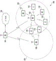
Fig. 7 illustrates a network 700 capable of decoding a data stream according to an embodiment of the disclosure. The embodiment of the network 700 shown in fig. 7 is for illustration only. Other embodiments may be used without departing from the scope of this disclosure.
In the illustrated embodiment, User Equipment (UE)713 and 714 are connected to the base station with cells via local base stations 701a and 701b A Base Station (BS) 701. The
 user equipment 711 is directly connected to the BS 701. Alternatively, UEs 712 and 715 are connected to have cells The
The BS 702.
The UEs 713 and 714 connected to the BS 701 are located far away from each other. UEs 712 and 715 connected to different BSs 702 are also remote from each other. However, UEs 711 and 712 are located in adjacent locations but are connected to two different base stations, that is, UE711 is connected to BS 701 and SS 712 is connected to BS 702.
User equipments located in adjacent locations to interfere with other user equipments above a specified threshold and connected to different cells respectively with other user equipments are denoted as 'high interference user equipments' for the present disclosure. For example, UEs 711 and 712 shown in fig. 7 are high interference user equipments. The specified threshold may be adjusted to various levels to meet the requirements of the service provider.
In some embodiments, the network 700 may send both cell-specific radio frequency resource control (RRC) and UE-specific RRC configurations to the user equipment. The cell-specific RRC configuration may include a cell-specific resource offset parameter for PUCCH HARQ-ACK. The UE-specific configuration may include a UE-specific RS base sequence parameter and a UE-specific resource offset parameter for PUCCH HARQ-ACK.
When the UE-specific RRC configuration is applicable to the user equipment, the user equipment may transmit a UE-specific PUCCH carrying HARQ-ACK, which is generated by a UE-specific RS generated using a UE-specific RS base sequence parameter and a UE-specific resource offset parameter for the PUCCH HARQ-ACK.
When the UE-specific RRC configuration is not applicable to the user equipment, the user equipment transmits a cell-specific PUCCH carrying HARQ-ACK, which is generated through a cell-specific reference signal generated with a cell-specific resource offset parameter for PUCCH HARQ-ACK.
In some embodiments, network 700 may send the same UE-specific RS base sequence and UE-specific resource offset parameters to UEs 711 and 712 with interference above a specified threshold. Thus, high- interference UEs 711 and 712 may transmit coordinated PUCCHs carrying HARQ-ACK information, which are generated using the same UE-specific RRC configuration.
In some embodiments, network 700 may send a UE-specific RRC configuration to UEs such as UEs 713, 714, and 715 whose interference is below a specified threshold. Thus, a low-interference UE may send a UE-specific PUCCH carrying HARQ-ACK information, which is generated based on the UE-specific RRC configuration.
In an embodiment, the network 700 may send the same UE-specific RS configuration base sequence parameters to the UEs 711 and 712. The UEs 711 and 712 transmit the PUCCH carrying HARQ-ACK using the same RS base sequence 1. Thus, UEs 711 and 712 cause less UL interference with each other. On the other hand, the UEs 713, 714, and 715 transmit UE-specific PUCCHs generated with UE-specific RS base sequences, which are RS base sequences 2, 3, and 4, respectively. Accordingly, PUCCHs transmitted from the user equipment may be orthogonal to each other. As described above, the threshold for determining whether high interference or low interference may be adjusted to meet various requirements of service providers.
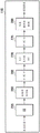
Fig. 8A and 8B illustrate PUCCH physical resource blocks designated for interfering user equipment according to an embodiment of the present disclosure. The embodiments of PUCCH physical resource blocks shown in fig. 8A and 8B are for illustration only. Other embodiments may be used without departing from the scope of this disclosure. The UE711 and 712 transmit the coordinated PUCCH carrying HARQ-ACK using the same RS base sequence 1. Thus, UEs 711 and 712 may reduce each other UL interference.
In some embodiments, the resource index number of the PUCCH is determined using the following formula

In formula 1, nCCEIs the number of the smallest Channel Control Element (CCE) used to transmit the corresponding downlink control information of the PDSCH for which the scheduled PUCCH carries HARQ-ACK information, in case UE-specific RRC configuration is applicable to the user equipment, is a UE specific resource offset parameter, otherwise
 Is a cell specific resource offset parameter.
In some embodiments, the UE-specific RRC configuration may contain an indication parameter indicating whether the UE-specific RRC configuration or the cell-specific RRC configuration is applicable to the user equipment. The indication parameter may have a value of TRUE (TRUE) or FALSE (FALSE), where TRUE refers to UE-specific RRC configuration being applicable to the user equipment and FALSE refers to cell-specific RRC configuration being applicable to the user equipment.
In some embodiments of the present invention, the, the content of 3GPP TS 36.211, release 10.1.0, "E-UTRA, physical channel and modulation" is hereby incorporated by reference and denoted as NCSI-RS of the present disclosure, can be derived from at least one of the CSI-RS configuration numbers associated with the non-zero CSI-RS transmission power defined in table 6.10.5.2-1 in 3GPP TS 36.211, release 10.1.0, "E-UTRA, physical channel and modulation", as follows:
the NCSI-RS may be a CSI-RS configuration number of an original base station from which the user equipment receives the PDCCH;
the NCSI-RS may be the smallest CSI-RS configuration number among all such CSI-RS configuration numbers; the NCSI-RS may be the largest CSI-RS configuration number among all such CSI-RS configuration numbers; or the NCSI-RS may be a CSI-RS configuration number with a minimum subframe configuration, and the RRC parameter is used to configure the CSI-RS subframe period. Connections with more than one configuration number having the smallest subframe configuration may be disconnected by either the smallest CSI-RS configuration number or the largest CSI-RS configuration number.
In some embodiments, the network may semi-statically configure the RRC connection with RRC configuration The network dynamically indicates one of the N candidates by dynamic signaling
For example, the number of N candidates may be four, and a two-bit Information Element (IE) is included in the PDCCH, e.g., with the information used to generate the four (4) candidates Corresponding to the downlink grant. According to the values of IE in the following exemplary table 1,
 can be selected from four (4) candidates
 To select among them.
TABLE 1

In some embodiments, the number of candidates N may be two, and a one-bit Information Element (IE) is included in the PDCCH, e.g., with the information used to generate the two (2) candidates Corresponding to the downlink grant. According to the values of IE in the following exemplary Table 2, one
 Can be selected from two (2) candidates
 To select among them.
TABLE 2

In some embodiments, the resource index number of the PUCCH is determined using the following formula

In the formula 2, nCCEIs the number of the smallest Channel Control Element (CCE) used to transmit the corresponding downlink control information of the PDSCH for which the scheduled PUCCH carries HARQ-ACK information, in case UE-specific RRC configuration is applicable to the user equipment, is a UE specific resource offset parameter, otherwise
 Is a cell specific resource offset parameter.
In some embodiments of the present invention, the, derived from at least one of the following NCSI-RS:
the NCSI-RS may be a CSI-RS configuration number of an original base station from which the user equipment receives the PDCCH; the NCSI-RS may be the smallest CSI-RS configuration number among all such CSI-RS configuration numbers; the NCSI-RS may be the largest CSI-RS configuration number among all such CSI-RS configuration numbers; or the NCSI-RS may be a CSI-RS configuration number with a minimum subframe configuration, and the RRC parameter is used to configure the CSI-RS subframe period. Connections with more than one configuration number having the smallest subframe configuration may be disconnected by either the smallest CSI-RS configuration number or the largest CSI-RS configuration number.
Fig. 9 shows downlink resources in which an enhanced PDCCH (E-PDCCH) is in a PDSCH region. The embodiment of the downlink resources shown in fig. 9 is for illustration only. Other embodiments may be used without departing from the scope of this disclosure.
The E-PDCCH 905 increases intra-base station Downlink (DL) control capacity and mitigates inter-cell interference of downlink control. In some embodiments, PUCCH format 1/1a/1b resources may be generated by a Reference Signaling (RS) base sequence according to the location of the DL grant, that is, whether PDCCH or E-PDCCH 905 is used to convey the DL grant associated with HARQ-ACK feedback.
In some embodiments, when the user equipment receives E as shown in exemplary Table 3User equipment generates user equipment specific RS base sequence for PUCCH format 1/1a/1b upon corresponding downlink control information carried in PDCCH 905. Mapped for when user equipment receives DL grant in E-PDCCH 905 region In other words, n may be usedCCE
 Formula 1 or 2, nCCEIs the first CCE number carrying a DL grant in the E-PDCCH 905 region.
TABLE 3

According to one embodiment of the disclosure, a user equipment may generate an Uplink (UL) Reference Signaling (RS) base sequence Wherein v equals 0 for PUCCH and is configured to be 0 or 1 by RRC for SRS, and the sequence group number is derived from the following formula:
u=(fgh(ns)+fss) mod30, [ equation 3 ]]
In the formula 3, fgh(ns) Is a group hopping pattern, fssIs a sequence shift pattern. f. ofssIs equal to Sequence shift pattern for Physical Uplink Control Channel (PUCCH) when used to generate PUCCH, or fssIs equal to
 A sequence shift pattern for a Physical Uplink Shared Channel (PUSCH) when used to generate the PUSCH.
Group hopping pattern f for both PUSCH and PUCCHgh(ns) The same, and are given by:

in equation 4, the pseudo-random sequence c (i) is defined by section 7.2 of 3GPP TS No.36.211, release 10.1.0, "E-UTRA, physical channel and modulation," the contents of which are incorporated herein by reference in their entirety. The pseudo-random sequence generator should use c at the beginning of each radio frequency frameinit,SGHAnd (5) initializing. Sequence hopping applied only with length The reference signal of (1). For length
 The base sequence number v in the base sequence set is given by v ═ 0 for the reference signal of (1). For length
 For the reference signal of (2), time slot nsThe base sequence number v within the base sequence group in (1) is defined as:

the RRC-provided parameter sequence-hopping enabled determines whether sequence hopping is enabled. Sequence-hopping of the PUSCH of a given user equipment may be disabled, whether or not enabled on a cell basis, by higher layer parameter disabling sequence-group-hopping (Disable-sequence-hopping). The pseudo-random sequence generator should be used at the beginning of each radio frequency frame And (5) initializing.
In embodiments where Sequence Group Hopping (SGH) is off, the Sequence Hopping (SH) initialization seed is determined by:

in equation 6, wherein Is a sequence shift pattern for PUSCH, cinit,SGHIs a random seed for Sequence Group Hopping (SGH).
In some embodiments, a random seed c for Sequence Group Hopping (SGH) may be configuredinitSuch that interfering user equipments are allocated to the same Uplink (UL) Reference Signal (RS) base sequence.
In embodiments where Sequence Group Hopping (SGH) is on, fgh(ns) Equal to 0 and the sequence group number u consists of f onlyssDetermining either u ═ fssmod 30. According to other embodiments of the present disclosure, the sequence shift pattern f is configured using the following formulass:
For the Physical Uplink Control Channel (PUCCH) and the Sound Reference Signal (SRS),

in equation 7, N is a UE-specific RS base sequence parameter in case that the UE-specific RRC configuration is applicable to the user equipment; otherwise N is the cell identifier of the cell. N configurable by RRC configuration And
And and replacing the sum.
For a Physical Uplink Shared Channel (PUSCH) demodulation reference signal (DM RS),

in the formula 8, the process is described, is toSequence Shift Pattern, Δ 'from PUCCH'ssIs configured by RRC configuration.
In certain embodiments, Δ'ssCan be set to ΔssAs defined in 3GPP TS 36.211 release 8.9.0, which is hereby incorporated into the present disclosure as if fully set forth herein, and may be configured by RRC, such as RRC, or by dynamic signaling such that interfering user equipments are allocated to the same Uplink (UL) Reference Signal (RS) base sequence.
In another embodiment of the present disclosure, the first and second substrates are, may be zero and the Δ' ss may be specifically configured for the user equipment by RRC, such as RRC, or by dynamic signaling, such that high interference user equipments are allocated to the same Uplink (UL) Reference Signal (RS) base sequence. Thus, the sequence shift patterns of PUCCH, PUSCH DM RS and SRS may be configured specifically for the user equipment, for the user equipment.
In certain embodiments, Δ'ssAnd both may be configured by UE-specific RRC or dynamic signaling such that high interference user equipments are allocated to the same Uplink (UL) Reference Signal (RS) base sequence parameter.
In some embodiments of the present invention, the, the values may be configured from {0, 1...., 29} by RRC or dynamic signaling such that high interference user equipment is allocated to the same Uplink (UL) Reference Signal (RS) base sequence.
In certain embodiments, Δ'ssThe value may be configured from {0, 1...., 29} by RRC or dynamic signaling such that high interference user equipment is allocated to the same Uplink (UL) referenceSignal (RS) base sequence.
In certain embodiments, Δ'ssThe signaling may be dynamically signaled in an Uplink (UL) grant, such as Downlink Control Indication (DCI) format 0 or DCI format 4. Dynamic signaling selection of N candidate delta'ssOne of the values Δ'ssThe values are such that high interference user equipments are allocated to the same Uplink (UL) Reference Signal (RS) base sequence.
In certain embodiments, Δ'ssThe values may be configured by RRC from {0, 1...., 29} such that high interference user equipment is allocated to the same Uplink (UL) Reference Signal (RS) base sequence.
In certain embodiments, the network may configure for Δ 'through RRC'ssSemi-statically configuring a set of N candidates, the network dynamically selecting one of the N candidates delta 'through PDCCH signaling'ssSuch that high interference user equipments are allocated to the same Uplink (UL) Reference Signal (RS) base sequence.
For example, the number of candidate N may be four and a 2-bit Information Element (IE) may be included in the Uplink (UL) grant, as set in exemplary table 4 below.
TABLE 4


In another example, the number of candidate N may be 2, and a one-bit Information Element (IE) may be included in the Uplink (UL) grant, as set in exemplary table 5 below.
TABLE 5
| Indication ofΔ′ss1 bit IE | Delta 'of indication'ssValue of |
| 0 | First delta 'configured by RRC'ssValue of |
| 1 | Second Delta 'configured by RRC'ssValue of |
In some embodiments, for periodic SRS (A-SRS), the method may further include transmitting in a transmit grant, which may be a Downlink (DL) grant or an Uplink (UL) grant, such that high interference user equipments are allocated to the same Uplink (UL) Reference Signal (RS) base sequence.
N candidates The values are configured by higher layers such as RRC or dynamic signaling. E.g. N candidates
 The value has a set of 0, 1.., 29, or N candidates
 May be indicated as Δ 'indicated in Table 4 or Table 5'ss。
In some embodiments where SGH is turned off, base station 701 may configure for user equipment 711 for RS base sequence alignment of PUCCH for high interference user equipment And
And base station 702 can be configured for user equipment 712
In some embodiments, the sequence shift pattern f is configured using the following equationss:
For the Physical Uplink Control Channel (PUCCH) and the Sound Reference Signal (SRS),

for a Physical Uplink Shared Channel (PUSCH) demodulation reference signal (DM RS),


In some embodiments, the sequence shift pattern And
And at least one of which may be configured by RRC or by dynamic signaling, wherein
 Or
Or May be configured from {0, 1., 29} such that high interference user equipment is allocated to the same Uplink (UL) Reference Signal (RS) base sequence.
In some embodiments, the network may be targeted through RRC configuration The set of N candidates is semi-statically configured and the network dynamically selects one of the N candidates through PDCCH signaling
 Such that high interference user equipments are allocated to the same Uplink (UL) Reference Signal (RS) base sequence. For example, the number of candidate N may be four and a 2-bit Information Element (IE) may be included in the Uplink (UL) grant, as set in exemplary table 8 below.
TABLE 8

In another example, the number of candidate N may be 2, and a one-bit Information Element (IE) may be included in the UL grant, as set in the following exemplary table 9.
TABLE 9

In another embodiment, for periodic SRS (A-SRS), may be sent in a transmit grant, which may be a Downlink (DL) grant or an Uplink (UL) grant, configured such that high interference user equipments are allocated to the same Uplink (UL) Reference Signal (RS) base sequence. N candidates
 The values may be configured by higher layers such as RRC or dynamic signaling. E.g. N candidates
 The value has a set of 0, 1.., 29, or N candidates
 May be indicated as indicated in Table 8 or Table 9
According to the present disclosure, PUCCH decoding performance is improved. That is, the decoding failure probability for the same transmission power is reduced. Due to the UE-specific RS base sequence configuration, the performance gain comes mainly from the following aspects: PUCCH interference is reduced because two PUCCH signals are orthogonally multiplexed currently in the case of UL coordinated multipoint (CoMP) reception, where two cells cooperate to decode PUCCH generated with the same RS base sequence. In the case of coordinated multipoint (CoMP) scenarios, where a large number of user equipments are connected to the same macro base station, the uplink cell division gain can be improved by allocating UE-specific RRC configurations.
As used in this disclosure, a coordinated multipoint (CoMP) Transmission Point (TP) refers to a transmitter associated with CoMP transmission to a User Equipment (UE) in a subframe. The TPs may include Remote Radio Headers (RRHs), macro enodebs, femto enodebs, pico enodebs, base stations, and the like. In some embodiments, CoMP TPs may have different cell IDs. In other embodiments, CoMP TPs may share the same cell ID. A coordinated multipoint (CoMP) Reception Point (RP) refers to a receiver associated with CoMP transmission from a User Equipment (UE) in a subframe. The RPs may include Remote Radio Headers (RRHs), macro enodebs, femto enodebs, pico enodebs, base stations, and the like. In some embodiments, CoMP RPs may have different cell IDs. In other embodiments, CoMP RPs may share the same cell ID.
Although the present disclosure has been described with exemplary embodiments, various changes and modifications may be suggested to one skilled in the art. The present disclosure is intended to embrace these changes and modifications as fall within the scope of the appended claims.
Claims (16)
1. A user equipment, UE, comprising:
a receiver configured to receive downlink control information scheduling downlink data from a base station on a physical downlink control channel, PDCCH, and to receive downlink data from the base station on a physical downlink shared channel, PDSCH;
a controller configured to generate a physical uplink control channel, PUCCH, reference signal, RS; and
a transmitter configured to transmit hybrid automatic repeat and request acknowledgement (HARQ-ACK) information and a PUCCH RS on a PUCCH to a base station, the HARQ-ACK information being associated with downlink data,
wherein the PUCCH RS is generated based on the sequence shift pattern,
wherein the sequence shift pattern is determined based on the UE-specific RS base sequence parameter if the UE-specific RS base sequence parameter is configured to the UE, and otherwise the sequence shift pattern is determined based on the cell identification information.
2. The user equipment of claim 1, wherein the UE-specific RS base sequence parameter is received via radio resource control, RRC, signaling.
3. The user equipment of claim 1, wherein the PUCCH RS is generated by a sequence group number u derived from:
u=(fgh(ns)+fss)mod30,
wherein f isgh(ns) Is a group hopping pattern, and fssIs a sequence shift pattern.
4. The user equipment of claim 3, wherein the sequence shift pattern fssIs determined based on the following formula:

where N is a UE-specific RS basic sequence parameter or cell identification information.
5. A base station, comprising:
a transmitter configured to transmit downlink control information scheduling downlink data to a user equipment, UE, on a physical downlink control channel, PDCCH, and to transmit downlink data to the UE on a physical downlink shared channel, PDSCH; and
a receiver configured to receive hybrid automatic retransmission and request acknowledgement, HARQ-ACK, information and a physical uplink control channel, PUCCH, reference signal, RS, on a PUCCH from a UE, the HARQ-ACK information being associated with downlink data,
wherein the PUCCH RS is generated by the UE based on the sequence shift pattern,
wherein the sequence shift pattern is determined based on the UE-specific RS base sequence parameter if the UE-specific RS base sequence parameter is configured to the UE, and otherwise the sequence shift pattern is determined based on the cell identification information.
6. The base station of claim 5, wherein the UE-specific RS base sequence parameters are received by the UE via Radio Resource Control (RRC) signaling.
7. The base station of claim 5, wherein the PUCCH RS is generated with a sequence group number u derived from the following formula:
u=(fgh(ns)+fss)mod30,
wherein f isgh(ns) Is a group hopping pattern, and fssIs a sequence shift pattern.
8. The base station of claim 7, wherein the sequence shift pattern fssIs determined based on the following formula:

where N is a UE-specific RS basic sequence parameter or cell identification information.
9. A method performed by a User Equipment (UE), comprising:
receiving downlink control information for scheduling downlink data from a base station on a physical downlink control channel, PDCCH;
receiving downlink data from a base station on a physical downlink shared channel, PDSCH;
generating a Physical Uplink Control Channel (PUCCH) Reference Signal (RS); and
transmitting hybrid automatic repeat and request acknowledgement (HARQ-ACK) information and a PUCCH RS on a PUCCH to a base station, the HARQ-ACK information being associated with downlink data,
wherein the PUCCH RS is generated based on the sequence shift pattern,
wherein the sequence shift pattern is determined based on the UE-specific RS base sequence parameter if the UE-specific RS base sequence parameter is configured to the UE, and otherwise the sequence shift pattern is determined based on the cell identification information.
10. The method of claim 9, wherein the UE-specific RS base sequence parameter is received via radio resource control, RRC, signaling.
11. The method of claim 9, wherein the PUCCH RS is generated by a sequence group number u derived from:
u=(fgh(ns)+fss)mod30,
wherein f isgh(ns) Is a group hopping pattern, and fssIs a sequence shift pattern.
12. The method of claim 11, wherein the sequence shift pattern fssIs determined based on the following formula:

where N is a UE-specific RS basic sequence parameter or cell identification information.
13. A method performed by a base station, comprising:
transmitting downlink control information for scheduling downlink data to a User Equipment (UE) on a Physical Downlink Control Channel (PDCCH);
transmitting downlink data to the UE on a Physical Downlink Shared Channel (PDSCH); and
receiving hybrid automatic repeat and request acknowledgement, HARQ-ACK, information and a physical uplink control channel, PUCCH, reference signal, RS, on a PUCCH from the UE, the HARQ-ACK information being associated with downlink data,
wherein the PUCCH RS is generated by the UE based on the sequence shift pattern,
wherein the sequence shift pattern is determined based on the UE-specific RS base sequence parameter if the UE-specific RS base sequence parameter is configured to the UE, and otherwise the sequence shift pattern is determined based on the cell identification information.
14. The method of claim 13, wherein the UE-specific RS base sequence parameter is received by the UE via radio resource control, RRC, signaling.
15. The method of claim 13, wherein the PUCCH RS is generated by a sequence group number u derived from:
u=(fgh(ns)+fss)mod30,
wherein f isgh(ns) Is a group hopping pattern, and fssIs a sequence shift pattern.
16. The method of claim 15, wherein the sequence shift pattern fssIs determined based on the following formula:

where N is a UE-specific RS basic sequence parameter or cell identification information.
Applications Claiming Priority (5)
| Application Number | Priority Date | Filing Date | Title |
|---|---|---|---|
| US201161498989P | 2011-06-20 | 2011-06-20 | |
| US61/498,989 | 2011-06-20 | ||
| US13/525,095 | 2012-06-15 | ||
| US13/525,095 US8718003B2 (en) | 2011-06-20 | 2012-06-15 | System and method for an uplink control signal in wireless communication systems |
| CN201280035786.XA CN103688504B (en) | 2011-06-20 | 2012-06-20 | It is used for the system and method for uplink control signal in a wireless communication system |
Related Parent Applications (1)
| Application Number | Title | Priority Date | Filing Date |
|---|---|---|---|
| CN201280035786.XA Division CN103688504B (en) | 2011-06-20 | 2012-06-20 | It is used for the system and method for uplink control signal in a wireless communication system |
Publications (2)
| Publication Number | Publication Date |
|---|---|
| CN107257269A CN107257269A (en) | 2017-10-17 |
| CN107257269B true CN107257269B (en) | 2020-06-30 |
Family
ID=47353605
Family Applications (2)
| Application Number | Title | Priority Date | Filing Date |
|---|---|---|---|
| CN201710372802.9A Active CN107257269B (en) | 2011-06-20 | 2012-06-20 | System and method for uplink control signal in wireless communication system |
| CN201280035786.XA Active CN103688504B (en) | 2011-06-20 | 2012-06-20 | It is used for the system and method for uplink control signal in a wireless communication system |
Family Applications After (1)
| Application Number | Title | Priority Date | Filing Date |
|---|---|---|---|
| CN201280035786.XA Active CN103688504B (en) | 2011-06-20 | 2012-06-20 | It is used for the system and method for uplink control signal in a wireless communication system |
Country Status (9)
| Country | Link |
|---|---|
| US (3) | US8718003B2 (en) |
| EP (2) | EP3998729A1 (en) |
| JP (2) | JP6026523B2 (en) |
| KR (2) | KR102033020B1 (en) |
| CN (2) | CN107257269B (en) |
| AU (1) | AU2012274241B2 (en) |
| RU (1) | RU2597006C2 (en) |
| WO (1) | WO2012177046A2 (en) |
| ZA (1) | ZA201309025B (en) |
Families Citing this family (47)
| Publication number | Priority date | Publication date | Assignee | Title |
|---|---|---|---|---|
| EP2495887B1 (en) | 2009-10-26 | 2020-03-18 | LG Electronics Inc. | Method and apparatus for transmitting reception acknowledgement information in wireless communication system |
| US8718003B2 (en) * | 2011-06-20 | 2014-05-06 | Samsung Electronics Co., Ltd. | System and method for an uplink control signal in wireless communication systems |
| US9246656B2 (en) | 2011-06-24 | 2016-01-26 | Lg Electronics Inc. | Method for transmitting uplink control information, user equipment, method for receiving uplink control information, and base station |
| US9544790B2 (en) | 2011-06-28 | 2017-01-10 | Lg Electronics Inc. | Method for monitoring downlink control information (DCI) and a user equipment using the same |
| ES2674925T3 (en) * | 2011-06-30 | 2018-07-05 | Telefonaktiebolaget Lm Ericsson (Publ) | Method and device for managing base sequences in a communications network |
| JP2013017016A (en) * | 2011-07-04 | 2013-01-24 | Sharp Corp | Base station device, mobile station device, communication system and communication method |
| JP5811443B2 (en) * | 2011-07-22 | 2015-11-11 | シャープ株式会社 | Terminal device, base station device, integrated circuit, and communication method |
| JP5895388B2 (en) * | 2011-07-22 | 2016-03-30 | シャープ株式会社 | Terminal device, base station device, integrated circuit, and communication method |
| US9794955B2 (en) * | 2011-08-15 | 2017-10-17 | Texas Instruments Incorporated | Configuration of CSI-RS for CoMP feedback |
| CN106658732B (en) * | 2011-08-15 | 2020-04-14 | 华为技术有限公司 | Method and device for allocating control channel resources |
| US10205569B2 (en) * | 2011-08-26 | 2019-02-12 | Lg Electronics Inc. | Method and user equipment for receiving downlink signals, and method and base station for transmitting downlink signals |
| US9497741B2 (en) * | 2011-09-26 | 2016-11-15 | Lg Electronics Inc. | Method and apparatus for transmitting and receiving uplink control information in radio access system |
| WO2013111525A1 (en) * | 2012-01-25 | 2013-08-01 | パナソニック株式会社 | Terminal, base station, transmission method, and reception method |
| WO2013147476A1 (en) | 2012-03-24 | 2013-10-03 | 엘지전자 주식회사 | Method and apparatus for transmitting and receiving reference signal in wireless communication system |
| CN108880755B (en) | 2012-05-11 | 2021-06-15 | 太阳专利信托公司 | Wireless communication terminal device, wireless communication method, and integrated circuit |
| CN104854773B (en) | 2013-01-14 | 2018-05-11 | 英特尔Ip公司 | Energy acquisition equipment in wireless network |
| US10624075B2 (en) * | 2013-03-16 | 2020-04-14 | Qualcomm Incorporated | Apparatus and method for scheduling delayed ACKs/NACKs in LTE cellular systems |
| JP6424393B2 (en) * | 2013-09-26 | 2018-11-21 | シャープ株式会社 | Terminal device, base station device, and communication method |
| KR102199693B1 (en) | 2013-11-01 | 2021-01-07 | 후아웨이 테크놀러지 컴퍼니 리미티드 | Apparatus and Method for Cancelling Inter-cell Interference in Wireless Communication System |
| US9641310B2 (en) * | 2013-12-13 | 2017-05-02 | Qualcomm Incorporated | Network assisted interference cancellation signaling |
| CN104767595A (en) * | 2014-01-07 | 2015-07-08 | 中兴通讯股份有限公司 | HARQ-ACK (Hybrid Automatic Repeated Request Acknowledge) feedback information transmission method, system, terminal and base station |
| CN106105084B (en) * | 2014-03-12 | 2019-07-12 | Lg电子株式会社 | The method and device thereof of uplink control channel are sent in the wireless communication system for the use variation for supporting radio resource |
| WO2015197110A1 (en) * | 2014-06-24 | 2015-12-30 | Huawei Technologies Co., Ltd. | Method and apparatus for multiple access in a wireless communication system |
| CN111918349B (en) | 2014-08-15 | 2023-05-12 | 交互数字专利控股公司 | WTRU and method for implementing same |
| US9629066B2 (en) * | 2015-02-24 | 2017-04-18 | Huawei Technologies Co., Ltd. | System and method for transmission time intervals |
| HUE043320T2 (en) * | 2015-02-26 | 2019-08-28 | Intel Ip Corp | Systems, methods and devices for radio access technology coordination |
| CN106059726B (en) * | 2015-04-17 | 2019-06-25 | 中国移动通信集团公司 | A kind of uplink control channel resource determines method and device |
| US11026142B2 (en) * | 2016-01-20 | 2021-06-01 | Qualcomm Incorporated | Techniques for providing uplink-based mobility |
| CN109314617B (en) * | 2016-06-30 | 2023-03-03 | 苹果公司 | Method for CRC ambiguity avoidance in 5G DCI decoding |
| US10541785B2 (en) * | 2016-07-18 | 2020-01-21 | Samsung Electronics Co., Ltd. | Carrier aggregation with variable transmission durations |
| WO2018142264A1 (en) * | 2017-02-01 | 2018-08-09 | Telefonaktiebolaget Lm Ericsson (Publ) | Methods and nodes for activation or deactivation of a carrier in a communication network supporting carrier aggregation |
| US11483810B2 (en) | 2017-04-03 | 2022-10-25 | Huawei Technologies Co., Ltd. | Methods and systems for resource configuration of wireless communication systems |
| US10798704B2 (en) * | 2017-04-28 | 2020-10-06 | Qualcomm Incorporated | Reference signal design for slot aggregation |
| JP6997802B2 (en) * | 2017-05-05 | 2022-01-18 | テレフオンアクチーボラゲット エルエム エリクソン(パブル) | Approval resource allocation |
| KR102662410B1 (en) | 2017-08-11 | 2024-05-03 | 주식회사 윌러스표준기술연구소 | Method, device, and system for transmitting or receiving uplink control channel in wireless communication system |
| US11166274B2 (en) * | 2017-08-24 | 2021-11-02 | Qualcomm Incorporated | User equipment-specific hybrid automatic repeat request timeline offset |
| US10644765B2 (en) * | 2017-10-24 | 2020-05-05 | Intel Corporation | Enhanced acknowledgment and power saving for wireless communications |
| CN109802811B (en) * | 2017-11-17 | 2021-05-18 | 北京紫光展锐通信技术有限公司 | Physical layer uplink control channel PUCCH resource configuration method and user terminal |
| CN109818895B (en) * | 2017-11-17 | 2022-04-29 | 中兴通讯股份有限公司 | Method and device for determining sequence group and method and device for determining cyclic shift |
| WO2019134128A1 (en) | 2018-01-05 | 2019-07-11 | Nec Corporation | Method and devices for uplink signal transmitting and receiving in a wireless communication system |
| CN108401508B (en) * | 2018-01-31 | 2022-01-18 | 北京小米移动软件有限公司 | Configuration parameter sending and reading methods and devices, base station and user equipment |
| US11051331B2 (en) * | 2018-05-11 | 2021-06-29 | Qualcomm Incorporated | Techniques and apparatuses for paired physical downlink shared channel and physical uplink shared channel scheduling |
| PL3836442T3 (en) * | 2018-08-08 | 2024-05-06 | Beijing Xiaomi Mobile Software Co., Ltd. | Hybrid automatic repeat request (harq) feedback method and apparatus |
| CN110932820B (en) | 2018-09-19 | 2022-01-14 | 华为技术有限公司 | Method for transmitting and receiving uplink control information and communication device |
| US20200092068A1 (en) * | 2018-09-19 | 2020-03-19 | Qualcomm Incorporated | Acknowledgement codebook design for multiple transmission reception points |
| CN113366896B (en) * | 2019-02-03 | 2022-11-04 | 华为技术有限公司 | Reference signal receiving and sending method, device and system |
| CN112398623B (en) * | 2019-08-16 | 2022-03-29 | 华为技术有限公司 | HARQ-ACK resource determination method for hybrid automatic repeat request acknowledgement |
Citations (5)
| Publication number | Priority date | Publication date | Assignee | Title |
|---|---|---|---|---|
| KR20090112534A (en) * | 2008-04-23 | 2009-10-28 | 엘지전자 주식회사 | Generation Method of the Uplink Reference Signal Sequence |
| CN101616360A (en) * | 2009-07-24 | 2009-12-30 | 中兴通讯股份有限公司 | A kind of sending method of location reference signals and system |
| CN101702644A (en) * | 2009-11-02 | 2010-05-05 | 中兴通讯股份有限公司 | Transmission method of physical mixed retransmission indicating channel (PHICH) and device thereof |
| CN101931961A (en) * | 2009-06-23 | 2010-12-29 | 华为技术有限公司 | Method, system and equipment for realizing return link control channel transmission of relay system |
| CN101960736A (en) * | 2008-02-28 | 2011-01-26 | Lg电子株式会社 | Method for multiplexing data and control information |
Family Cites Families (28)
| Publication number | Priority date | Publication date | Assignee | Title |
|---|---|---|---|---|
| US2A (en) * | 1826-12-15 | 1836-07-29 | mode of manufacturing wool or other fibrous materials | |
| KR100735225B1 (en) * | 2003-07-12 | 2007-07-03 | 삼성전자주식회사 | Method for Managing Vocoder Resource in a Mobile Communication System |
| KR101376233B1 (en) * | 2007-10-02 | 2014-03-21 | 삼성전자주식회사 | Apparatus and method for allocating control channel in a frequency division multiple access system |
| EP3026834B1 (en) * | 2007-10-29 | 2017-07-19 | Panasonic Corporation | Radio communication device and constellation control method |
| US9036564B2 (en) * | 2008-03-28 | 2015-05-19 | Qualcomm Incorporated | Dynamic assignment of ACK resource in a wireless communication system |
| US8259602B2 (en) * | 2008-04-21 | 2012-09-04 | Lg Electronics Inc. | Method of transmitting control signal in wireless communication system |
| KR101589600B1 (en) * | 2008-08-05 | 2016-01-28 | 삼성전자주식회사 | Method and apparatus for transmitting and receiving uplink acknowledgement channel for downlink data channel in mobile communication systems using orthogonal frequency division multiple access |
| KR101441147B1 (en) * | 2008-08-12 | 2014-09-18 | 엘지전자 주식회사 | Method of transmitting sr in wireless communication system |
| KR101629298B1 (en) * | 2008-10-30 | 2016-06-10 | 엘지전자 주식회사 | Method of transmitting control signal in wireless communication system and appratus therefore |
| JP5538802B2 (en) * | 2008-11-04 | 2014-07-02 | 三菱電機株式会社 | COMMUNICATION METHOD, MOBILE COMMUNICATION SYSTEM, MOBILE TERMINAL, AND BASE STATION CONTROL DEVICE |
| KR101667826B1 (en) * | 2008-11-04 | 2016-10-19 | 애플 인크. | Providing a downlink control structure in a first carrier to indicate control information in a second, different carrier |
| WO2010056078A2 (en) * | 2008-11-14 | 2010-05-20 | 엘지전자주식회사 | Method and apparatus for information transmission in wireless communication system |
| WO2010070197A1 (en) * | 2008-12-15 | 2010-06-24 | Nokia Corporation | Downlink control and physical hybrid arq indicator channel (phich) configuration for extended bandwidth system |
| US20100271970A1 (en) | 2009-04-22 | 2010-10-28 | Interdigital Patent Holdings, Inc. | Method and apparatus for transmitting uplink control information for carrier aggregated spectrums |
| WO2011019795A1 (en) * | 2009-08-13 | 2011-02-17 | Interdigital Patent Holdings, Inc. | Multiplexing uplink l1/l2 control and data |
| US8467799B2 (en) | 2009-08-20 | 2013-06-18 | Samsung Electronics Co., Ltd. | Method and system for assigning physical uplink control channel (PUCCH) resources |
| BR112012007487A2 (en) * | 2009-10-01 | 2017-08-22 | Interdigital Patent Holdings Inc | UPLINK CONTROL DATA TRANSMISSION |
| WO2011049354A2 (en) | 2009-10-19 | 2011-04-28 | Samsung Electronics Co., Ltd. | Transmission diversity and multiplexing for harq-ack signals in communication systems |
| US8576755B2 (en) * | 2010-01-11 | 2013-11-05 | Qualcomm Incorporated | Apparatus and method for relay transition time |
| KR101915134B1 (en) * | 2010-03-11 | 2018-11-05 | 엘지전자 주식회사 | Control channel allocation method, and apparatus for same |
| EP2553860B1 (en) * | 2010-04-02 | 2016-06-01 | InterDigital Patent Holdings, Inc. | Uplink sounding reference signals configuration and transmission |
| WO2011137408A2 (en) * | 2010-04-30 | 2011-11-03 | Interdigital Patent Holdings, Inc. | Determination of carriers and multiplexing for uplink control information transmission |
| US9258092B2 (en) * | 2010-09-17 | 2016-02-09 | Blackberry Limited | Sounding reference signal transmission in carrier aggregation |
| CN105721118B (en) * | 2010-09-19 | 2019-04-23 | Lg电子株式会社 | The method and apparatus for sending control information |
| WO2012044764A2 (en) * | 2010-10-01 | 2012-04-05 | Research In Motion Limited | Orthogonal resource selection transmit diversity and resource assignment |
| US8514826B2 (en) * | 2010-11-02 | 2013-08-20 | Lg Electronics Inc. | Method and apparatus for transmitting control information in radio communication system |
| US9413509B2 (en) * | 2011-06-17 | 2016-08-09 | Texas Instruments Incorporated | Hybrid automatic repeat request acknowledge resource allocation for enhanced physical downlink control channel |
| US8718003B2 (en) * | 2011-06-20 | 2014-05-06 | Samsung Electronics Co., Ltd. | System and method for an uplink control signal in wireless communication systems |
-
2012
- 2012-06-15 US US13/525,095 patent/US8718003B2/en active Active
- 2012-06-20 EP EP21197982.8A patent/EP3998729A1/en active Pending
- 2012-06-20 KR KR1020137033785A patent/KR102033020B1/en active IP Right Grant
- 2012-06-20 AU AU2012274241A patent/AU2012274241B2/en active Active
- 2012-06-20 EP EP12803140.8A patent/EP2721794B1/en active Active
- 2012-06-20 KR KR1020197029783A patent/KR102301970B1/en active IP Right Grant
- 2012-06-20 CN CN201710372802.9A patent/CN107257269B/en active Active
- 2012-06-20 RU RU2013156689/07A patent/RU2597006C2/en active
- 2012-06-20 WO PCT/KR2012/004873 patent/WO2012177046A2/en unknown
- 2012-06-20 JP JP2014516913A patent/JP6026523B2/en active Active
- 2012-06-20 CN CN201280035786.XA patent/CN103688504B/en active Active
-
2013
- 2013-12-02 ZA ZA2013/09025A patent/ZA201309025B/en unknown
-
2014
- 2014-03-28 US US14/229,235 patent/US8902786B2/en active Active
- 2014-12-02 US US14/558,286 patent/US9357538B2/en active Active
-
2016
- 2016-10-12 JP JP2016200720A patent/JP6328720B2/en active Active
Patent Citations (5)
| Publication number | Priority date | Publication date | Assignee | Title |
|---|---|---|---|---|
| CN101960736A (en) * | 2008-02-28 | 2011-01-26 | Lg电子株式会社 | Method for multiplexing data and control information |
| KR20090112534A (en) * | 2008-04-23 | 2009-10-28 | 엘지전자 주식회사 | Generation Method of the Uplink Reference Signal Sequence |
| CN101931961A (en) * | 2009-06-23 | 2010-12-29 | 华为技术有限公司 | Method, system and equipment for realizing return link control channel transmission of relay system |
| CN101616360A (en) * | 2009-07-24 | 2009-12-30 | 中兴通讯股份有限公司 | A kind of sending method of location reference signals and system |
| CN101702644A (en) * | 2009-11-02 | 2010-05-05 | 中兴通讯股份有限公司 | Transmission method of physical mixed retransmission indicating channel (PHICH) and device thereof |
Also Published As
| Publication number | Publication date |
|---|---|
| CN107257269A (en) | 2017-10-17 |
| EP2721794A4 (en) | 2016-03-02 |
| US20120320847A1 (en) | 2012-12-20 |
| WO2012177046A3 (en) | 2013-04-04 |
| US20140226581A1 (en) | 2014-08-14 |
| KR20140037133A (en) | 2014-03-26 |
| JP2014523677A (en) | 2014-09-11 |
| EP2721794B1 (en) | 2021-09-22 |
| US9357538B2 (en) | 2016-05-31 |
| ZA201309025B (en) | 2015-06-24 |
| JP2017063435A (en) | 2017-03-30 |
| US8718003B2 (en) | 2014-05-06 |
| WO2012177046A2 (en) | 2012-12-27 |
| CN103688504B (en) | 2017-06-20 |
| AU2012274241A1 (en) | 2013-10-31 |
| EP2721794A2 (en) | 2014-04-23 |
| US20150131582A1 (en) | 2015-05-14 |
| JP6328720B2 (en) | 2018-05-23 |
| RU2597006C2 (en) | 2016-09-10 |
| JP6026523B2 (en) | 2016-11-16 |
| EP3998729A1 (en) | 2022-05-18 |
| RU2013156689A (en) | 2015-06-27 |
| KR102301970B1 (en) | 2021-09-15 |
| AU2012274241B2 (en) | 2016-07-07 |
| KR20190118686A (en) | 2019-10-18 |
| US8902786B2 (en) | 2014-12-02 |
| KR102033020B1 (en) | 2019-11-08 |
| CN103688504A (en) | 2014-03-26 |
Similar Documents
| Publication | Publication Date | Title |
|---|---|---|
| CN107257269B (en) | System and method for uplink control signal in wireless communication system | |
| US10652874B2 (en) | User equipment, network node and methods therein for determining transport block size in downlink transmissions in a telecommunications system | |
| US8565066B2 (en) | System and method for an uplink acknowledgement transmission in carrier-aggregated wireless communication systems | |
| EP2406897B1 (en) | Method and apparatus for uplink transmissions and cqi reports with carrier aggregation | |
| KR101899907B1 (en) | Method and system for uplink acknowledgement signaling in carrier-aggregated wireless communication systems | |
| KR101838203B1 (en) | Methods and apparatus for multi-user mimo transmissions in wireless communication systems | |
| KR101776097B1 (en) | Method and system for mapping uplink control information | |
| RU2563249C2 (en) | Radio base station, user terminal and radio communication method | |
| CN105379391B (en) | Terminal, base station and communication means | |
| US20120230258A1 (en) | Radio communication control method, base station apparatus and mobile terminal apparatus | |
| WO2010079977A2 (en) | System and method for downlink physical indicator channel mapping with asymmetric carrier aggregation | |
| US20180063819A1 (en) | Radio base station, user terminal and radio communication method | |
| CN110063078A (en) | The method and device thereof of multiple Transmission Time Intervals are supported in a wireless communication system |
Legal Events
| Date | Code | Title | Description |
|---|---|---|---|
| PB01 | Publication | ||
| PB01 | Publication | ||
| SE01 | Entry into force of request for substantive examination | ||
| SE01 | Entry into force of request for substantive examination | ||
| GR01 | Patent grant | ||
| GR01 | Patent grant |