CN107211151B - Cross-component predictive clipping and adaptive color transform for video coding - Google Patents
Cross-component predictive clipping and adaptive color transform for video coding Download PDFInfo
- Publication number
- CN107211151B CN107211151B CN201680006123.3A CN201680006123A CN107211151B CN 107211151 B CN107211151 B CN 107211151B CN 201680006123 A CN201680006123 A CN 201680006123A CN 107211151 B CN107211151 B CN 107211151B
- Authority
- CN
- China
- Prior art keywords
- video
- residual data
- transform
- bit depth
- inverse
- Prior art date
- Legal status (The legal status is an assumption and is not a legal conclusion. Google has not performed a legal analysis and makes no representation as to the accuracy of the status listed.)
- Active
Links
Images


Classifications
-
- H—ELECTRICITY
- H04—ELECTRIC COMMUNICATION TECHNIQUE
- H04N—PICTORIAL COMMUNICATION, e.g. TELEVISION
- H04N9/00—Details of colour television systems
- H04N9/79—Processing of colour television signals in connection with recording
-
- H—ELECTRICITY
- H04—ELECTRIC COMMUNICATION TECHNIQUE
- H04N—PICTORIAL COMMUNICATION, e.g. TELEVISION
- H04N11/00—Colour television systems
- H04N11/02—Colour television systems with bandwidth reduction
-
- H—ELECTRICITY
- H04—ELECTRIC COMMUNICATION TECHNIQUE
- H04N—PICTORIAL COMMUNICATION, e.g. TELEVISION
- H04N11/00—Colour television systems
- H04N11/04—Colour television systems using pulse code modulation
- H04N11/042—Codec means
-
- H—ELECTRICITY
- H04—ELECTRIC COMMUNICATION TECHNIQUE
- H04N—PICTORIAL COMMUNICATION, e.g. TELEVISION
- H04N11/00—Colour television systems
- H04N11/04—Colour television systems using pulse code modulation
- H04N11/042—Codec means
- H04N11/044—Codec means involving transform coding
-
- H—ELECTRICITY
- H04—ELECTRIC COMMUNICATION TECHNIQUE
- H04N—PICTORIAL COMMUNICATION, e.g. TELEVISION
- H04N11/00—Colour television systems
- H04N11/24—High-definition television systems
-
- H—ELECTRICITY
- H04—ELECTRIC COMMUNICATION TECHNIQUE
- H04N—PICTORIAL COMMUNICATION, e.g. TELEVISION
- H04N19/00—Methods or arrangements for coding, decoding, compressing or decompressing digital video signals
- H04N19/10—Methods or arrangements for coding, decoding, compressing or decompressing digital video signals using adaptive coding
- H04N19/102—Methods or arrangements for coding, decoding, compressing or decompressing digital video signals using adaptive coding characterised by the element, parameter or selection affected or controlled by the adaptive coding
- H04N19/124—Quantisation
-
- H—ELECTRICITY
- H04—ELECTRIC COMMUNICATION TECHNIQUE
- H04N—PICTORIAL COMMUNICATION, e.g. TELEVISION
- H04N19/00—Methods or arrangements for coding, decoding, compressing or decompressing digital video signals
- H04N19/10—Methods or arrangements for coding, decoding, compressing or decompressing digital video signals using adaptive coding
- H04N19/102—Methods or arrangements for coding, decoding, compressing or decompressing digital video signals using adaptive coding characterised by the element, parameter or selection affected or controlled by the adaptive coding
- H04N19/13—Adaptive entropy coding, e.g. adaptive variable length coding [AVLC] or context adaptive binary arithmetic coding [CABAC]
-
- H—ELECTRICITY
- H04—ELECTRIC COMMUNICATION TECHNIQUE
- H04N—PICTORIAL COMMUNICATION, e.g. TELEVISION
- H04N19/00—Methods or arrangements for coding, decoding, compressing or decompressing digital video signals
- H04N19/10—Methods or arrangements for coding, decoding, compressing or decompressing digital video signals using adaptive coding
- H04N19/134—Methods or arrangements for coding, decoding, compressing or decompressing digital video signals using adaptive coding characterised by the element, parameter or criterion affecting or controlling the adaptive coding
- H04N19/146—Data rate or code amount at the encoder output
- H04N19/149—Data rate or code amount at the encoder output by estimating the code amount by means of a model, e.g. mathematical model or statistical model
-
- H—ELECTRICITY
- H04—ELECTRIC COMMUNICATION TECHNIQUE
- H04N—PICTORIAL COMMUNICATION, e.g. TELEVISION
- H04N19/00—Methods or arrangements for coding, decoding, compressing or decompressing digital video signals
- H04N19/10—Methods or arrangements for coding, decoding, compressing or decompressing digital video signals using adaptive coding
- H04N19/169—Methods or arrangements for coding, decoding, compressing or decompressing digital video signals using adaptive coding characterised by the coding unit, i.e. the structural portion or semantic portion of the video signal being the object or the subject of the adaptive coding
- H04N19/17—Methods or arrangements for coding, decoding, compressing or decompressing digital video signals using adaptive coding characterised by the coding unit, i.e. the structural portion or semantic portion of the video signal being the object or the subject of the adaptive coding the unit being an image region, e.g. an object
- H04N19/176—Methods or arrangements for coding, decoding, compressing or decompressing digital video signals using adaptive coding characterised by the coding unit, i.e. the structural portion or semantic portion of the video signal being the object or the subject of the adaptive coding the unit being an image region, e.g. an object the region being a block, e.g. a macroblock
-
- H—ELECTRICITY
- H04—ELECTRIC COMMUNICATION TECHNIQUE
- H04N—PICTORIAL COMMUNICATION, e.g. TELEVISION
- H04N19/00—Methods or arrangements for coding, decoding, compressing or decompressing digital video signals
- H04N19/10—Methods or arrangements for coding, decoding, compressing or decompressing digital video signals using adaptive coding
- H04N19/169—Methods or arrangements for coding, decoding, compressing or decompressing digital video signals using adaptive coding characterised by the coding unit, i.e. the structural portion or semantic portion of the video signal being the object or the subject of the adaptive coding
- H04N19/186—Methods or arrangements for coding, decoding, compressing or decompressing digital video signals using adaptive coding characterised by the coding unit, i.e. the structural portion or semantic portion of the video signal being the object or the subject of the adaptive coding the unit being a colour or a chrominance component
-
- H—ELECTRICITY
- H04—ELECTRIC COMMUNICATION TECHNIQUE
- H04N—PICTORIAL COMMUNICATION, e.g. TELEVISION
- H04N19/00—Methods or arrangements for coding, decoding, compressing or decompressing digital video signals
- H04N19/42—Methods or arrangements for coding, decoding, compressing or decompressing digital video signals characterised by implementation details or hardware specially adapted for video compression or decompression, e.g. dedicated software implementation
-
- H—ELECTRICITY
- H04—ELECTRIC COMMUNICATION TECHNIQUE
- H04N—PICTORIAL COMMUNICATION, e.g. TELEVISION
- H04N19/00—Methods or arrangements for coding, decoding, compressing or decompressing digital video signals
- H04N19/44—Decoders specially adapted therefor, e.g. video decoders which are asymmetric with respect to the encoder
-
- H—ELECTRICITY
- H04—ELECTRIC COMMUNICATION TECHNIQUE
- H04N—PICTORIAL COMMUNICATION, e.g. TELEVISION
- H04N19/00—Methods or arrangements for coding, decoding, compressing or decompressing digital video signals
- H04N19/50—Methods or arrangements for coding, decoding, compressing or decompressing digital video signals using predictive coding
- H04N19/503—Methods or arrangements for coding, decoding, compressing or decompressing digital video signals using predictive coding involving temporal prediction
- H04N19/51—Motion estimation or motion compensation
- H04N19/513—Processing of motion vectors
- H04N19/517—Processing of motion vectors by encoding
- H04N19/52—Processing of motion vectors by encoding by predictive encoding
-
- H—ELECTRICITY
- H04—ELECTRIC COMMUNICATION TECHNIQUE
- H04N—PICTORIAL COMMUNICATION, e.g. TELEVISION
- H04N19/00—Methods or arrangements for coding, decoding, compressing or decompressing digital video signals
- H04N19/60—Methods or arrangements for coding, decoding, compressing or decompressing digital video signals using transform coding
- H04N19/61—Methods or arrangements for coding, decoding, compressing or decompressing digital video signals using transform coding in combination with predictive coding
-
- H—ELECTRICITY
- H04—ELECTRIC COMMUNICATION TECHNIQUE
- H04N—PICTORIAL COMMUNICATION, e.g. TELEVISION
- H04N19/00—Methods or arrangements for coding, decoding, compressing or decompressing digital video signals
- H04N19/60—Methods or arrangements for coding, decoding, compressing or decompressing digital video signals using transform coding
- H04N19/625—Methods or arrangements for coding, decoding, compressing or decompressing digital video signals using transform coding using discrete cosine transform [DCT]
-
- H—ELECTRICITY
- H04—ELECTRIC COMMUNICATION TECHNIQUE
- H04N—PICTORIAL COMMUNICATION, e.g. TELEVISION
- H04N19/00—Methods or arrangements for coding, decoding, compressing or decompressing digital video signals
- H04N19/80—Details of filtering operations specially adapted for video compression, e.g. for pixel interpolation
- H04N19/82—Details of filtering operations specially adapted for video compression, e.g. for pixel interpolation involving filtering within a prediction loop
-
- H—ELECTRICITY
- H04—ELECTRIC COMMUNICATION TECHNIQUE
- H04N—PICTORIAL COMMUNICATION, e.g. TELEVISION
- H04N19/00—Methods or arrangements for coding, decoding, compressing or decompressing digital video signals
- H04N19/90—Methods or arrangements for coding, decoding, compressing or decompressing digital video signals using coding techniques not provided for in groups H04N19/10-H04N19/85, e.g. fractals
- H04N19/96—Tree coding, e.g. quad-tree coding
-
- H—ELECTRICITY
- H04—ELECTRIC COMMUNICATION TECHNIQUE
- H04N—PICTORIAL COMMUNICATION, e.g. TELEVISION
- H04N21/00—Selective content distribution, e.g. interactive television or video on demand [VOD]
- H04N21/20—Servers specifically adapted for the distribution of content, e.g. VOD servers; Operations thereof
- H04N21/23—Processing of content or additional data; Elementary server operations; Server middleware
- H04N21/238—Interfacing the downstream path of the transmission network, e.g. adapting the transmission rate of a video stream to network bandwidth; Processing of multiplex streams
- H04N21/2383—Channel coding or modulation of digital bit-stream, e.g. QPSK modulation
-
- H—ELECTRICITY
- H04—ELECTRIC COMMUNICATION TECHNIQUE
- H04N—PICTORIAL COMMUNICATION, e.g. TELEVISION
- H04N21/00—Selective content distribution, e.g. interactive television or video on demand [VOD]
- H04N21/40—Client devices specifically adapted for the reception of or interaction with content, e.g. set-top-box [STB]; Operations thereof
- H04N21/43—Processing of content or additional data, e.g. demultiplexing additional data from a digital video stream; Elementary client operations, e.g. monitoring of home network or synchronising decoder's clock; Client middleware
- H04N21/438—Interfacing the downstream path of the transmission network originating from a server, e.g. retrieving MPEG packets from an IP network
- H04N21/4382—Demodulation or channel decoding, e.g. QPSK demodulation
-
- H—ELECTRICITY
- H04—ELECTRIC COMMUNICATION TECHNIQUE
- H04N—PICTORIAL COMMUNICATION, e.g. TELEVISION
- H04N21/00—Selective content distribution, e.g. interactive television or video on demand [VOD]
- H04N21/60—Network structure or processes for video distribution between server and client or between remote clients; Control signalling between clients, server and network components; Transmission of management data between server and client, e.g. sending from server to client commands for recording incoming content stream; Communication details between server and client
- H04N21/61—Network physical structure; Signal processing
- H04N21/6106—Network physical structure; Signal processing specially adapted to the downstream path of the transmission network
- H04N21/6131—Network physical structure; Signal processing specially adapted to the downstream path of the transmission network involving transmission via a mobile phone network
-
- H—ELECTRICITY
- H04—ELECTRIC COMMUNICATION TECHNIQUE
- H04N—PICTORIAL COMMUNICATION, e.g. TELEVISION
- H04N21/00—Selective content distribution, e.g. interactive television or video on demand [VOD]
- H04N21/60—Network structure or processes for video distribution between server and client or between remote clients; Control signalling between clients, server and network components; Transmission of management data between server and client, e.g. sending from server to client commands for recording incoming content stream; Communication details between server and client
- H04N21/61—Network physical structure; Signal processing
- H04N21/6156—Network physical structure; Signal processing specially adapted to the upstream path of the transmission network
- H04N21/6181—Network physical structure; Signal processing specially adapted to the upstream path of the transmission network involving transmission via a mobile phone network
-
- H—ELECTRICITY
- H04—ELECTRIC COMMUNICATION TECHNIQUE
- H04N—PICTORIAL COMMUNICATION, e.g. TELEVISION
- H04N9/00—Details of colour television systems
- H04N9/64—Circuits for processing colour signals
-
- H—ELECTRICITY
- H04—ELECTRIC COMMUNICATION TECHNIQUE
- H04N—PICTORIAL COMMUNICATION, e.g. TELEVISION
- H04N19/00—Methods or arrangements for coding, decoding, compressing or decompressing digital video signals
- H04N19/10—Methods or arrangements for coding, decoding, compressing or decompressing digital video signals using adaptive coding
- H04N19/169—Methods or arrangements for coding, decoding, compressing or decompressing digital video signals using adaptive coding characterised by the coding unit, i.e. the structural portion or semantic portion of the video signal being the object or the subject of the adaptive coding
- H04N19/184—Methods or arrangements for coding, decoding, compressing or decompressing digital video signals using adaptive coding characterised by the coding unit, i.e. the structural portion or semantic portion of the video signal being the object or the subject of the adaptive coding the unit being bits, e.g. of the compressed video stream
-
- H—ELECTRICITY
- H04—ELECTRIC COMMUNICATION TECHNIQUE
- H04N—PICTORIAL COMMUNICATION, e.g. TELEVISION
- H04N25/00—Circuitry of solid-state image sensors [SSIS]; Control thereof
- H04N25/50—Control of the SSIS exposure
- H04N25/57—Control of the dynamic range
Landscapes
- Engineering & Computer Science (AREA)
- Multimedia (AREA)
- Signal Processing (AREA)
- General Physics & Mathematics (AREA)
- Physics & Mathematics (AREA)
- Mathematical Analysis (AREA)
- Algebra (AREA)
- Mathematical Optimization (AREA)
- Pure & Applied Mathematics (AREA)
- Computer Networks & Wireless Communication (AREA)
- Discrete Mathematics (AREA)
- Compression Or Coding Systems Of Tv Signals (AREA)
- Color Television Systems (AREA)
Abstract
A device for encoding or decoding video data may clip first residual data based on a bit depth of the first residual data. The device may generate second residual data at least in part by applying an inverse adaptive color transform, IACT, to the first residual data. Moreover, the device may reconstruct coding blocks of a coding unit, CU, of the video data based on the second residual data.
Description
This application claims the benefit of U.S. provisional patent application 62/110,324, 2015, U.S. provisional patent application 62/113,269, 2015, 2-month 6-day, and U.S. provisional patent application 62/115,487, 2015, 2-month 12-day, each of which is incorporated herein by reference in its entirety.
Technical Field
The present disclosure relates to video coding.
Background
Digital video capabilities can be incorporated into a wide range of devices, including digital televisions, digital direct broadcast systems, wireless broadcast systems, Personal Digital Assistants (PDAs), laptop or desktop computers, tablet computers, e-book readers, digital cameras, digital recording devices, digital media players, video gaming devices, video game consoles, cellular or satellite radio telephones (so-called "smart phones"), video teleconferencing devices, video streaming devices, and the like. Digital video devices implement video coding techniques such as the video coding techniques described in the standards defined by MPEG-2, MPEG-4, ITU-T H.263, ITU-T H.264/MPEG-4, Part 10, Advanced Video Coding (AVC), ITU-T H.265, High Efficiency Video Coding (HEVC), and extensions of these standards, such as Scalable Video Coding (SVC), Multiview Video Coding (MVC), Scalable HEVC (SHVC), multiview HEVC (MV-HEVC), 3D-HEVC, and HEVC range extensions. Video devices may transmit, receive, encode, decode, and/or store digital video information more efficiently by implementing these video coding techniques.
Video coding techniques include spatial (intra-picture) prediction and/or temporal (inter-picture) prediction to reduce or remove redundancy inherent in video sequences. For block-based video coding, a video slice (e.g., a video frame or portion of a video frame) may be partitioned into video blocks, which may also be referred to as treeblocks, Coding Treeblocks (CTUs), Coding Units (CUs), and/or coding nodes. The video blocks may include luma blocks and chroma blocks. In an intra-coded (I) slice of a picture, a block is encoded using spatial prediction with respect to reference samples in neighboring blocks in the same picture. Video blocks in inter-coded (P or B) slices of a picture may use spatial prediction with respect to reference samples in neighboring blocks in the same picture or temporal prediction with respect to reference samples in other reference pictures. A picture may be referred to as a frame and a reference picture may be referred to as a reference frame.
Spatial or temporal prediction generates a predictive block for a block to be coded. The residual data represents the pixel differences between the original block to be coded and the predictive block. An inter-coded block is encoded according to a motion vector that points to a block of reference samples that forms a predictive block and residual data that indicates a difference between the coded block and the predictive block. The intra-coded block is encoded according to an intra-coding mode and the residual data. For further compression, the residual data may be transformed from the pixel domain to a transform domain, producing residual transform coefficients that may then be quantized. The quantized transform coefficients may be entropy coded to achieve even more compression.
Disclosure of Invention
The present disclosure relates to the field of video coding, and more particularly, to bit depth considerations when applying tools such as Adaptive Color Transform (ACT) and cross-component prediction (CCP). Certain techniques of this disclosure may reduce, eliminate, or otherwise control the bit depth increase of samples due to the application of ACT and CCP.
In one aspect, this disclosure describes a method of encoding or decoding video data, the method comprising: clipping first residual data to a variable range based on a bit depth of the first residual data; generating second residual data at least in part by applying an Inverse Adaptive Color Transform (IACT) to the clipped first residual data; and reconstructing a coding block of a Coding Unit (CU) of the video data based on the second residual data.
In another aspect, this disclosure describes a device for encoding or decoding video data, the device comprising: a memory configured to store the video data; and one or more processors configured to: clipping first residual data to a variable range based on a bit depth of the first residual data; generating second inverse transformed residual data at least in part by applying an Inverse Adaptive Color Transform (IACT) to the clipped first residual data; and reconstruct a coding block of a Coding Unit (CU) of the video data based on the second inverse transformed residual data.
In another aspect, this disclosure describes a device for encoding or decoding video data, the device comprising: means for clipping first residual data to a variable range based on a bit depth of the first residual data; means for generating second residual data at least in part by applying an Inverse Adaptive Color Transform (IACT) to the clipped first residual data; and means for reconstructing a coding block of a Coding Unit (CU) of the video data based on the second inverse transformed residual data.
In another aspect, this disclosure describes a computer-readable storage medium having stored thereon instructions that, when executed, cause one or more processors of a device for encoding or decoding video data to: clipping first residual data to a variable range based on a bit depth of the first residual data; generating second residual data at least in part by applying an Inverse Adaptive Color Transform (IACT) to the clipped first residual data; and reconstructing a coding block of a Coding Unit (CU) of the video data based on the second residual data.
The details of one or more examples of the invention are set forth in the accompanying drawings and the description below. Other features, objects, and advantages will be apparent from the description and drawings, and from the claims.
Drawings
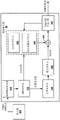
FIG. 1 is a block diagram illustrating an example video coding system that may utilize techniques of this disclosure.
Fig. 2 is a conceptual diagram illustrating an example Adaptive Color Transform (ACT) and cross-component prediction (CCP) processing order.
Fig. 3 is a conceptual diagram illustrating an example High Efficiency Video Coding (HEVC) coded input/output (IO) bit depth.
Fig. 4A is a conceptual diagram illustrating example bit depth information for a configuration for screen content coding using CCPs.
Fig. 4B is a conceptual diagram illustrating example bit depth information for a configuration of screen content coding using ACT and CCP.
Fig. 5A is a conceptual diagram illustrating a clip employing CCP only after a forward CCP in accordance with one or more techniques of this disclosure.
Fig. 5B is a conceptual diagram illustrating a dynamic range change attributable to a clip that only employs a CCP after a forward CCP in accordance with one or more techniques of this disclosure.
Fig. 5C is a conceptual diagram illustrating clipping with ACT and CCP after the forward CCP in accordance with one or more techniques of this disclosure.
Fig. 5D is a conceptual diagram illustrating the dynamic range changes attributable to a clip employing ACT and CCP subsequent to a forward CCP in accordance with one or more techniques of this disclosure.
Fig. 6A is a conceptual diagram illustrating example clip positions at a video decoder, according to one or more techniques of this disclosure.
Fig. 6B is a conceptual diagram illustrating an example of a clip at the clip location indicated in fig. 6A.
Fig. 6C is a conceptual diagram illustrating an example of a clip at the clip location indicated in fig. 6A.
Fig. 6D is a conceptual diagram illustrating an example of a clip at the clip location indicated in fig. 6A.
Fig. 7 is a conceptual diagram illustrating an example of clipping at the inverse ACT input, where the previous modules were used for inverse ccp (iccp), in accordance with one or more techniques of this disclosure.
Fig. 8 is a conceptual diagram illustrating an example of clipping at the inverse ACT input, where the previous module was used for the inverse transform, according to one or more techniques of this disclosure.
Fig. 9A is a conceptual diagram illustrating a series of example transformations in which input to an ICCP is subject to constraints, in accordance with one or more techniques of this disclosure.
Fig. 9B is a conceptual diagram illustrating a series of example transformations in which input to the IACT is subject to constraints, in accordance with one or more techniques of this disclosure.
Fig. 9C is a conceptual diagram showing a series of example transformations of the condensed forms of fig. 9A and 9B, in accordance with an illustration of one or more techniques of this disclosure.
Fig. 10 is a block diagram illustrating an example of a video encoder that may perform techniques in accordance with one or more aspects of this disclosure.
Fig. 11 is a block diagram illustrating an example of a video decoder that may perform techniques in accordance with one or more aspects of this disclosure.
Fig. 12 is a flow diagram illustrating example operation of a video coder, in accordance with the techniques of this disclosure.
Detailed Description
High Efficiency Video Coding (HEVC) is a recently finalized video coding standard. HEVC extensions for Screen Content Coding (SCC) are under development. The SCC extension of HEVC implements Adaptive Color Transform (ACT) and cross-component prediction (CCP) transforms to reduce redundancy among color components. This disclosure relates generally to the field of video coding, and more particularly, to bit depth considerations when applying tools such as ACT and CCP. The proposed techniques are primarily related to SCC, but are generally applicable to HEVC extensions and other video coding standards, including standards that support high bit depths (e.g., greater than 8 bits), different chroma sampling formats, and so on.
In the SCC extension of HEVC, a video encoder may generate residual data that indicates differences between samples of a coded block of video data and corresponding samples of a predictive block. The video encoder may then apply ACT to the residual data to obtain a first set of transformed residual data. The video encoder may then apply the CCP transform to the first set of transformed residual data to obtain a second set of transformed residual data. Subsequently, the video encoder may apply a transform (T), such as a Discrete Cosine Transform (DCT), to the second set of transformed residual data to obtain a third set of transformed residual data. In contrast to the first and second sets of transformed residual data, the third set of transformed residual data may be in the frequency domain rather than the sample domain. The residual data in the "frequency domain" is represented in terms of a function (e.g., a cosine function or a sine function) that oscillates at different frequencies. Residual data in the "sample domain" is represented in terms of sample values (e.g., luma values or chroma values) of the video data. The video encoder may then quantize the third set of transformed residual data.
The video decoder may reverse this process. For example, the video decoder may obtain a syntax element indicating the quantized third set of transformed residual data. The video decoder may then inverse quantize the third set of transformed residual data to regenerate the third set of transformed residual data. Next, the video decoder may apply an Inverse Transform (IT), such as an inverse DCT, to regenerate the second set of transformed residual data. The video decoder may then apply an inverse ccp (iccp) transform to the regenerated second set of transformed residual data to regenerate the first set of transformed residual data. Subsequently, the video decoder may apply the inverse act (iact) to the regenerated first set of transformed residual data to regenerate the residual data. The video decoder may reconstruct the coding block based on the regenerated residual data and the predictive block.
In the process outlined above, each sample of the second set of transformed residual data that is regenerated (i.e., the output of the IT) has a bit depth that is 7 bits greater than the original bit depth of the samples of the coding block. In this context, the term "bit depth" refers to the number of bits used to represent a single sample. Furthermore, each sample of the second set of transformed residual data that is regenerated (i.e., the output of the ICCP transform) has a bit depth that is 8 bits greater than the original bit depth of the samples of the coding block. Each sample of the first set of transformed residual data that is regenerated (i.e., the output of the IACT) has a bit depth that is 9 bits greater than the original bit depth of the samples of the coding block.
The increased bit depth associated with using ACT and CCP transforms may increase implementation complexity and cost for video encoders and video decoders. For example, in a hardware implementation of a video encoder and a video decoder, a data path for carrying and storing samples of transformed residual data may require more channels and/or storage locations.
This disclosure describes techniques that reduce or eliminate the bit depth increase associated with using ACT and CCP transforms in video coding. For example, as part of a process to decode video data, a video decoder may clip the first residual data to a variable range based on a bit depth of the first residual data. Clipping may refer to a process of setting a value to an upper limit value if the value exceeds the upper limit value and setting the value to a lower limit value if the value is less than the lower limit value. In some examples, the video decoder may apply ICCP to generate the first residual data. In some examples, a video decoder may apply a transform from a transform domain to a sample domain to generate first residual data without applying ICCP. Next, the video decoder may generate second residual data at least in part by applying the IACT to the clipped input. Thus, the video decoder may clip the input to the IACT based on the bit depth of the input to the IACT. The video decoder may reconstruct a coding block of a Coding Unit (CU) of the video data based on the second residual data. For example, the video decoder may reconstruct the coding blocks of the CU such that, for each respective sample of the coding block that corresponds to a sample in the second residual data, the respective sample of the coding block is equal to the corresponding sample in the second residual data plus the corresponding sample in the predictive block of the Prediction Unit (PU) of the CU. The video encoder may perform the same or similar process as part of the reconstruction loop (i.e., the decoding loop) of the video encoder. Advantageously, the process described in this example may prevent the bit depth from increasing beyond a certain number when ACT and/or CCP are used.
FIG. 1 is a block diagram illustrating an example video coding system 10 that may utilize techniques of this disclosure. As used herein, the term "video coder" generally refers to both video encoders and video decoders. In this disclosure, the term "video coding" or "coding" may generally refer to video encoding or video decoding. According to various examples described in this disclosure, video encoder 20 and video decoder 30 of video coding system 10 represent examples of devices that may be configured to perform techniques for video coding.
As shown in fig. 1, video coding system 10 includes a source device 12 and a destination device 14. Source device 12 generates encoded video data. Accordingly, source device 12 may be referred to as a video encoding device or a video encoding apparatus. Destination device 14 may decode the encoded video data generated by source device 12. Destination device 14 may, therefore, be referred to as a video decoding device or a video decoding apparatus. Source device 12 and destination device 14 may be examples of video coding devices or video coding apparatuses.
In another example, channel 16 may include a storage medium that stores encoded video data generated by source device 12. In this example, destination device 14 may access the storage medium, such as via disk access or card access. The storage medium may comprise a variety of locally-accessed data storage media such as a Blu-ray disc, DVD, CD-ROM, flash memory, or other suitable digital storage medium for storing encoded video data.
In another example, channel 16 may include a file server or another intermediate storage device that stores the encoded video data generated by source device 12. In this example, destination device 14 may access encoded video data stored at a file server or another intermediate storage device via streaming or download. The file server may be a type of server capable of storing encoded video data and transmitting the encoded video data to destination device 14. Example file servers include web servers (e.g., for a website), File Transfer Protocol (FTP) servers, Network Attached Storage (NAS) devices, and local disk drives.
The techniques of this disclosure are not limited to wireless applications or settings. The techniques may be applied to video coding to support a variety of multimedia applications, such as over-the-air television broadcasts, cable television transmissions, satellite television transmissions, streaming video transmissions (e.g., via the internet), encoding of video data for storage on a data storage medium, decoding of video data stored on a data storage medium, or other applications. In some examples, video coding system 10 may be configured to support one-way or two-way video transmission to support applications such as video streaming, video playback, video broadcasting, and/or video telephony.
The video coding system 10 illustrated in fig. 1 is merely an example, and the techniques of this disclosure may be applied to video coding settings (e.g., video encoding or video decoding) that do not necessarily include any data communication between an encoding device and a decoding device. In other examples, the data is retrieved from local memory, streamed over a network, and so on. A video encoding device may encode and store data to memory, and/or a video decoding device may retrieve and decode data from memory. In many examples, the encoding and decoding are performed by devices that do not communicate with each other, but merely encode data to and/or retrieve and decode data from memory. Video encoder 20 and video decoder 30 may include memories configured to store video data. Video encoder 20 may encode video data stored in memory. Video decoder 30 may decode the encoded video data and store the resulting video data in memory.
In the example of fig. 1, source device 12 includes a video source 18, a video encoder 20, and an output interface 22. In some examples, output interface 22 may include a modulator/demodulator (modem) and/or a transmitter. Video source 18 may include a video capture device (e.g., a video camera), a video archive containing previously captured video data, a video feed interface to receive video data from a video content provider, and/or a computer graphics system for generating video data, or a combination of these sources of video data.
In the example of fig. 1, destination device 14 includes an input interface 28, a video decoder 30, and a display device 32. In some examples, input interface 28 includes a receiver and/or a modem. Input interface 28 may receive encoded video data via channel 16. The display device 32 may be integrated with the destination device 14 or may be external to the destination device 14. In general, display device 32 displays the decoded video data. The display device 32 may include a variety of display devices, such as a Liquid Crystal Display (LCD), a plasma display, an Organic Light Emitting Diode (OLED) display, or another type of display device.
This disclosure may generally refer to video encoder 20 "signaling" or "transmitting" certain information to another device, such as video decoder 30. The term "signaling" or "transmission" may generally refer to communication of syntax elements and/or other data used to decode compressed video data. This communication may occur in real time or near real time. Alternatively, such communication may occur over a span of time, such as may occur when, at the time of encoding, syntax elements are stored to a computer-readable storage medium in an encoded bitstream, which then may be retrieved by a decoding device at any time after storage to such medium.
In the example of fig. 1, source device 12 and destination device 14 may each comprise a wireless communication device. Source device 12 may comprise a transmitter communicatively coupled to one or more processors of source device 12. In other words, the one or more processors of source device 12 may be directly or indirectly coupled to the transmitter in a manner that allows the one or more processors of source device 12 to communicate with the transmitter. The output interface 22 may comprise a transmitter. The transmitter may be configured to transmit a bitstream comprising an encoded representation of the video data. Such an encoded representation of video data may comprise an encoded representation of a coding unit, for example. Similarly, destination device 14 may comprise a receiver communicatively coupled to one or more processors of destination device 14. In other words, the one or more processors of destination device 14 may be directly or indirectly coupled to the receiver in a manner that allows the one or more processors of destination device 14 to communicate with the receiver. The input interface 28 may comprise a receiver. The receiver may be configured to receive a bitstream comprising an encoded representation of video data. In some examples, the wireless communication device is a cellular telephone and the bit stream is modulated according to a cellular communication standard. In these examples, the bitstream may be transmitted by a transmitter, or the bitstream may be received by a receiver.
Recently, the design of a new video coding standard, namely High Efficiency Video Coding (HEVC), has been finalized by the video coding joint collaboration group (JCT-VC) of the ITU-T Video Coding Experts Group (VCEG) and the ISO/IEC Moving Picture Experts Group (MPEG). In some examples, video encoder 20 and video decoder 30 operate according to a video compression standard, such as the HEVC standard. "High Efficiency Video Coding (HEVC) Defect Report 2" (file JCTVC-01003_ v2 available from http:// phenix.int-evry.fr/JCT/doc _ end _ user/documents/15_ Geneva/WG11/JCTVC-O1003-v2.zip) of Wang et al at the video Coding joint collaboration team (JCT-VC) 15 th meeting, held in W.W.W.W.T. 16WP3 and ISO/IEC JTC1/SC29/WG11 from 10.E.T. 23 to 11.E.1 of 2013, held in W.T. in Switzerland is referred to hereinafter as HEVC WD. "High Efficiency Video Coding (HEVC) Defect report 4" (file JCTVC-Q1003(v.1), available from http:// phenix. int-ry. fr/JCT/doc end _ user/documents/17_ Valencia/WG11/JCTVC-Q1003-v1.zip) (hereinafter, HEVC 1) is another file describing the HEVC standard, in the Video Coding joint collaboration team (JCT-VC) 17 th meeting at Wang et al, held in Valencia, 3.27.2014.4.4.2014.Banspanish. Recommendation ITU-T H.265 (high efficiency video coding, available from http:// www.itu.int/REC/T-REC-H.265-201304-I) is another file containing the latest HEVC specification. In addition to the base HEVC standard, there are ongoing efforts to generate scalable video coding, multiview video coding, and 3D coding extensions for HEVC.
An HEVC range extension, another extension to the HEVC standard, adds support for HEVC for additional color representations (also referred to as "color formats") and for increased color bit depth. A range extension to HEVC, which may be referred to as "HEVC RExt," is also being developed by JCT-VC. Recent drafts for HEVC range extension are: "High Efficiency Video Coding (HEVC) Range extensions description: Draft 7" by Flynn et al, at 17 th conference of the Video Coding Joint collaboration team (JCT-VC), held in Valencia, Spain, 27 th to 4 th, 2014, 4 th, and ISO/IEC JTC1/SC29/WG11, available from http:// phenix. int-ry. ev.fr/JCT/doc _ end _ user/documents/17_ Valencia/WG11/JCTVC-Q1005-v9. zip. Another recent Working Draft (WD), hereinafter referred to as the HEVC range extension of RExtWD7, is described in Flynn et al's High Efficiency Video Coding (HEVC) Range specification: Draft 7 ' at Flynn's joint collaborative team (JCT-VC) 17 th conference, held in Valencia, Spain, from 3.month 27 to 4.month 4, 2014, which is available from http:// phenix. int-ev.fr/JCT/doc _ end _ user/documentations/17 _ Valencia/g 11/JCTVC-Q1005-V4. zip.
As indicated above, HEVC range extensions may add support for HEVC for increased color bit depth. The color bit depth is the number of bits used to represent each component of the color representation. Support for other color formats may include support for red-green-blue (RGB) sources used to encode and decode video data, as well as video data with other color representations and using different chroma subsampling patterns compared to the HEVC main profile.
The range extension specification may become version 2 of HEVC. However, to a large extent, HEVC version 1 and HEVC range extension specifications are technically similar with respect to proposed techniques involving this disclosure (e.g., motion vector prediction). Thus, whenever the present disclosure refers to a change based on HEVC version 1, the same change may be applied to the HEVC range extension specification, and whenever the present disclosure reuses the HEVC version 1 module, the present disclosure may also actually reuse the HEVC range extension module (with the same secondary clause).
Another extension of HEVC for coding screen content material, such as text and graphics with motion, i.e., Screen Content Coding (SCC), is also being developed. The latest Working Draft (WD) of SCC ("High Efficiency Video Coding (HEVC)" Screen content Coding: Draft 1 "of Joshi et al at the 18 th conference of the Video Coding Joint collaboration team (JCT-VC) of ISO/IEC JTC1/SC29/WG11 and ITU-T SG16WP3 held by Japanese Sappoporo on 6.30.7.9.2014, and JCT/IEC JTC1/SC29/WG11, the document JCTVC-R1005_ v3 (hereinafter," JCTVC-R1005 ")) can be obtained from http:// phenix.int-evry.fr/JCT/doc _ end _ user/documents/18_ Sapporo/WG11/JCTVC-R1005-v3. zip.
In HEVC and other video coding standards, a video sequence typically includes a series of pictures. Pictures may also be referred to as "frames". A picture may contain three arrays of samples, denoted as SL、SCbAnd SCr。SLIs a two-dimensional array (i.e., block) of luma samples. SCbIs a two-dimensional array of Cb chroma samples. SCrIs a two-dimensional array of Cr chroma samples. Chroma samples may also be referred to herein as "chroma" samples. In other cases, a picture may be monochrome and may include only an array of luma samples.
To generate an encoded representation of a picture, video encoder 20 may generate a set of Coding Tree Units (CTUs). Each of the CTUs may be a coding tree block of luma samples, two corresponding coding tree blocks of chroma samples, and syntax structures used to code samples of the coding tree blocks. The coding tree block may be an nxn block of samples. A CTU may also be referred to as a "tree block" or a "largest coding unit" (LCU). A slice may include an integer number of CTUs ordered consecutively in a raster scan.
To generate an encoded CTU, video encoder 20 may recursively perform quadtree partitioning on a coding tree block of the CTU to divide the coding tree block into coding blocks, hence the name "coding tree unit. The coded block is an nxn block of samples. A Coding Unit (CU) may be a coding block of luma samples and two corresponding coding blocks of chroma samples of a picture having a luma sample array, a Cb sample array, and a Cr sample array, and syntax structures used to code the samples of the coding block. In a monochrome picture or a picture having three separate color planes, a CU may comprise a single coding block, and syntax structures used to code the samples of the coding block.
After video encoder 20 generates predictive blocks (e.g., predictive luma, Cb, and Cr blocks) for one or more PUs of the CU, video encoder 20 may generate residual blocks for the CU. Each sample in the residual block of the CU indicates a difference between a sample in a predictive block for a PU of the CU and a corresponding sample in a coding block of the CU. For example, video encoder 20 may generate a luma residual block for a CU. Each sample in the luma residual block of the CU indicates a difference between a luma sample in the predictive luma block of a PU of the CU and a corresponding sample in the luma coding block of the CU. In addition, video encoder 20 may generate Cb residual blocks for the CU. Each sample in the Cb residual block of the CU may indicate a difference between a Cb sample in a predictive Cb block of a PU of the CU and a corresponding sample in a Cb coding block of the CU. Video encoder 20 may also generate a Cr residual block for the CU. Each sample in the Cr residual block of the CU may indicate a difference between a Cr sample in a predictive Cr block for a PU of the CU and a corresponding sample in a Cr coding block of the CU.
Moreover, video encoder 20 may use quadtree partitioning to decompose residual blocks (e.g., luma, Cb, and Cr residual blocks) of a CU into one or more transform blocks (e.g., luma, Cb, and Cr transform blocks). The transform block may be a rectangular block of samples to which the same transform is applied. A Transform Unit (TU) of a CU may be a transform block of luma samples, two corresponding transform blocks of chroma samples, and syntax structures used to transform the transform block samples. Thus, each TU of a CU may be associated with a luma transform block, a Cb transform block, and a Cr transform block. A luma transform block associated with a TU may be a sub-block of a luma residual block of a CU. The Cb transform block may be a sub-block of a Cb residual block of the CU. The Cr transform block may be a sub-block of a Cr residual block of the CU. In a monochrome picture or a picture having three separate color planes, a TU may comprise a single transform block, and syntax structures used to transform the samples of the transform block.
After generating the coefficient blocks (e.g., luma coefficient blocks, Cb coefficient blocks, or Cr coefficient blocks), video encoder 20 may quantize the coefficient blocks. Quantization generally refers to a process by which transform coefficients are quantized to possibly reduce the amount of data used to represent the transform coefficients to provide further compression. After video encoder 20 quantizes the coefficient block, video encoder 20 may entropy encode syntax elements indicating the quantized transform coefficients. For example, video encoder 20 may perform Context Adaptive Binary Arithmetic Coding (CABAC) on syntax elements indicative of quantized transform coefficients. Video encoder 20 may output the entropy-encoded syntax elements in a bitstream. The bitstream may comprise an encoded representation of the video data.
Different types of NAL units may encapsulate different types of RBSPs. For example, a first type of NAL unit may encapsulate RBSPs for a Picture Parameter Set (PPS), a second type of NAL unit may encapsulate RBSPs for a coded slice, a third type of NAL unit may encapsulate RBSPs for Supplemental Enhancement Information (SEI), and so on. NAL units that encapsulate RBSPs for video coding data (as opposed to RBSPs for parameter sets and SEI messages) may be referred to as Video Coding Layer (VCL) NAL units.
In the example of fig. 1, video decoder 30 receives a bitstream generated by video encoder 20. In addition, video decoder 30 may parse the bitstream to obtain the syntax elements from the bitstream. Video decoder 30 may reconstruct pictures of the video data based at least in part on syntax elements obtained from the bitstream. The process to reconstruct the video data may be substantially reciprocal to the process performed by video encoder 20. For example, video decoder 30 may use intra prediction or inter prediction to determine the predictive blocks for the PUs of the current CU. In addition, video decoder 30 may inverse quantize coefficient blocks for TUs of the current CU. Video decoder 30 may perform inverse transforms on the coefficient blocks to regenerate the transform blocks for the TUs of the current CU. Video decoder 30 may reconstruct the coding block of the current CU by adding samples of the predictive blocks for the PUs of the current CU to corresponding samples of the transform blocks for the TUs of the current CU. Video decoder 30 may reconstruct the picture by reconstructing the coding blocks for each CU of the picture.
The pixels of each block of video data each represent a color in a particular format (referred to as a "color representation"). Different video coding standards may use different color representations for blocks of video data. As one example, the master profile of the HEVC video standard uses YCbCr color representation to represent pixels of a block of video data.
YCbCr color representation generally refers to the color representation by which each pixel of video data is represented by three components or channels of color information, "Y", "Cb", and "Cr". The Y channel represents brightness (i.e., light intensity or brightness) data for a particular pixel. The Cb and Cr components are the blue-difference and red-difference chroma (i.e., "chroma") components, respectively. YCbCr is often used to represent colors in compressed video data because there is a strong decorrelation between Y, Cb and each of the Cr components, meaning that there is little duplicate or redundant data between Y, Cb and each of the Cr components. Coding video data using YCbCr color representations thus provides good compression performance in many cases.
In addition, many video coding techniques utilize a technique referred to as "chroma subsampling" to further improve the compression of the color data. Chroma subsampling of video data with a YCbCr color representation reduces the number of chroma values signaled in the coded video bitstream by selectively omitting chroma components according to the pattern. In a block of chroma subsampled video data, there is typically a luma value for each pixel of the block. However, only the Cb and Cr components may be signaled for some pixels of the block, such that the chroma components are subsampled relative to the luma components.
A video coder (i.e., a video encoder or a video decoder) may interpolate Cb and Cr components for a pixel, where the Cb and Cr values are not explicitly signaled for a chroma subsampled block of pixels. Chroma subsampling works well to reduce the amount of chroma data without introducing distortion in the more uniform block of pixels. Chroma subsampling is relatively poor for representing video data having widely different chroma values, and may introduce a large amount of distortion in those cases.
As mentioned above, the HEVC master profile uses YCbCr due to the substantially strong color decorrelation between the luma component and the two chroma components of the color representation (also referred to as color format). However, in some cases, there may still be a correlation between Y, Cb and the Cr component. The correlation between components of a color representation may be referred to as cross-color component correlation or inter-color component correlation.
A video coder may be configured to predict values of one component (e.g., samples of a chroma component) based on values of different components (e.g., samples of a luma component). The process of predicting samples from a first component based on a second component is referred to as "cross-component prediction for color video" or "inter-color-component prediction". The video coder may predict a value of the first component based on a correlation between the first component and the second component.
When video data is captured, it is often converted to an RGB color space for various pre-processing purposes. After pre-processing, for video coding, the video data is typically converted to YCbCr 4:2:0 for better compression efficiency. However, color conversion can cause color distortion, resulting in subjective quality degradation. The range extension of HEVC provides for video coding for color spaces other than YCbCr 4:2:0, such as YCbCr 4:2:2, YCbCr 4:4:4, and RGB 4:4: 4.
If the RGB data is directly compressed without a color transform (e.g., color conversion), coding efficiency may be reduced because redundancy between color channels is not reduced. On the other hand, conventional color conversion such as YCbCr may cause color distortion. Accordingly, it may be desirable to develop techniques that may achieve coding efficiency improvements with less color distortion.
The Screen Content Coding (SCC) of HEVC uses two coding tools to exploit redundancy among the three color components to achieve higher compression ratios, i.e., Adaptive Color Transform (ACT) and cross-component prediction (CCP). As described In "SCCE 5Test 3.2.1: In-loop color-space transform" (document JCTVC-R0147 (hereinafter, "JCTVC-R0147")) by l.zhang et al, on the 18 th conference of video coding joint collaboration group (JCT-VC) of ITU-T SG16WP3 and ISO/IEC JTC1/SC29/WG11, hosted by japanese sapoma In 2014, 30 th to 7 th, 9 th, ACT is an In-loop color space transform that uses cgyc transform matrices, defined as follows, for forward and reverse color space transforms followed by lossy coding:
forward: reversing:
in the above equations, the original color space (C0, C1, C2) may correspond to (R, G, B) or (Y, U, V).
CCP is a process used to predict chroma (or second and third components) from luma (or first component). CCP is described in "High Efficiency Video Coding (HEVC) screen content coding: Draft 2" (hereinafter, "JCTVC-S1005") of "Joshi and J.xu at conference No. 18 of ITU-T SG16WP3 held in Japanese Sappora at 30.6.7.9.2014 and video coding Joint collaboration team (JCT-VC) of ISO/IEC JTC1/SC29/WG 11. The equation for CCP is shown below:
forward:
-Y=Y
-
-
reversing:
-Y=Y
-
-
wherein α can be-8, -4, -2, -1,0,1,2,4,8 }.
Fig. 2 is a conceptual diagram illustrating an example ACT and CCP processing sequence. Both ACT and CCP are residue-based operations, and their corresponding processing order within the codec is shown in fig. 2. In the example of fig. 2, a video encoder (abbreviated "Enc" in fig. 2) performs a residual generation operation 48 to obtain residual data 50 (e.g., in a manner described elsewhere in this disclosure). The residual data 50 is abbreviated as "Res" in fig. 2. Further, in fig. 2, the video encoder applies ACT 52 to the residual data 50, thereby obtaining residual data 54. Next, the video encoder applies CCP transform 56 to residual data 54, thereby obtaining residual data 58. The video encoder then applies transform 60 to residual data 58, thereby obtaining residual data 62. The residual data 62 may be in the transform domain (e.g., frequency domain). Further, the video encoder may apply quantization operation 64 to residual data 62, thereby obtaining quantized residual data 66.
In fig. 2, the video decoder applies an inverse quantization operation 68 to the quantized residual data 66, thereby obtaining inverse quantized residual data 70. Next, the video decoder applies an inverse transform 72 to the inverse quantized residual data 70, thereby obtaining residual data 74. The residual data 74 may be in the sample domain. Further, the video decoder applies an inverse CCP transform (ICCP)76 to residual data 74, thereby obtaining residual data 78. Next, the video decoder applies the inverse act (iact)80 to the residual data 78 to obtain residual data 82. The video decoder may apply a reconstruction operation 84 to reconstruct the coding block based in part on the residual data 82. The video encoder may perform the portion of fig. 2 described with respect to the video decoder as part of the decoding loop.
Dynamic range analysis along the HEVC datapath has been studied in detail in IEEE trans.circuitsysst. Video technology. volume 23, pages 1131 to 1136, published in 7.2013, "Dynamic range analysis in High Efficiency Video Coding research and recovery" by c.yeo et al, and in 2011, pages 19 to 30, in 11.s.19.nd to 30. in suns. ITU-T SG16WP3 and the joint collaboration group of Video Coding (JCT-VC) of ISO/IEC c1/SC29/WG11, m.zhou, "AHG 7: IDCT Output range after T + Q + IQ + IT limited resource Inputs" (document JCTVC-G856) at conference 7.
Fig. 3 is a conceptual diagram illustrating an example HEVC coded input/output (IO) bit depth. As illustrated in fig. 3, a bit depth extension of up to 5 bits may occur in the reconstructed residual, where B bits are the bit depth of the input pixel and the prediction pixel. In particular, in fig. 3, the video encoder may perform a residual generation operation 100 to obtain residual data 102 (abbreviated as "Res" in fig. 3). Each sample of residual data 102 may have a bit depth of B + 1. Next, in fig. 3, the video encoder may apply transform 104 to residual data 102 to obtain residual data 106. The video encoder may apply a quantization operation 108 to the residual data 106, thereby obtaining quantized residual data 110.
In fig. 3, the video decoder may apply an inverse quantization operation 112 to the quantized residual data 110, thereby obtaining inverse quantized residual data 114. Next, the video decoder may apply an Inverse Transform (IT)116 to the inverse quantized residual data 114, thereby obtaining inverse transformed (e.g., inverse discrete cosine transformed or inverse sine transformed) residual data 118. IT116 may transform the residual data from a transform domain to a sample domain (i.e., a pixel domain). As shown in fig. 3, as a result of applying the inverse transform 116, each sample of residual data 118 may have a bit depth of B + 6. Furthermore, in fig. 3, the video decoder may apply a reconstruction operation 120 to the residual data 118 to reconstruct samples of the coding block. In fig. 3, the video decoder may apply a clipping operation as part of performing the reconstruction operation 120. The clipping operation may ensure that the bit-depth of the reconstructed samples of the coding block is equal to B.
Fig. 4A is a conceptual diagram illustrating example bit depth information for a configuration for screen content coding using CCPs. Fig. 4B is a conceptual diagram illustrating example bit depth information for a configuration of screen content coding using ACT and CCP. Fig. 4A and 4B are similar to fig. 3, but include CCP, and in fig. 4B include ACT. In fig. 4A, the video encoder applies CCP transform 150 to residual data 160 and the video decoder (or video encoder reconstruction loop) applies inverse CCP transform 152 to residual data 162 obtained by IT 116. In fig. 4B, the video encoder applies ACT 154 to the residual data 164, then applies CCP transform 150, and the video decoder (or video encoder re-loop) applies inverse CCP transform 152, then applies inverse ACT 156.
With regard to ACT and CCP operation of the SCC, the dynamic range extension is shown in fig. 4A and 4B, where IACT represents inverse ACT and ICCP represents inverse CCP. IT is clear from fig. 4A and 4B that the bit depth after the Inverse Transform (IT)116 is increased to (B +7) bits due to the addition of the forward CCP operation 150 and (in fig. 4B) the forward ACT operation 154. This increases the bit depth of the chroma residual (or residual delta) by one more bit to (B +2) bits. Because CCP is applied to only chroma residual data using luma residual data, the bit depth of the luma residual data is not changed by CCP.
As can be seen from the bit depth analysis in fig. 4A and 4B, the bit depth increase at the input of the transform may have a dynamic range effect along the data path (such as in the transpose buffer, ICCP, and IACT), which may result in higher implementation costs and may generally not be desirable in an implementation. The terms "dynamic range" and "bit depth" may be used interchangeably in this disclosure.
Techniques are proposed that can keep the bit depth constant or reduce the bit depth increase when ACT and CCP tools are enabled. For example, in a first example of this disclosure, it is proposed to apply a Clip operation at the video encoder after the forward CCP operation, such as Clip _ a shown in fig. 5A and 5B. The present disclosure proposes to clip the dynamic range of the output of the CCP to B +1 bits, where the B bits are the bit depth of the input pixels and the prediction pixels, so the dynamic range of the output of the CCP can be restored to the limit indicated in HEVC version 2(Recommendation ITU-T h.265, month 10 2014). Potential benefits of the techniques of this disclosure may include: there is no need to change the decoder side and maintain the dynamic range of the original data path, which can mean that existing designs do not need to have their bit depth changed along the data path.
Fig. 5A is a conceptual diagram illustrating a clip employing CCP only after a forward CCP in accordance with one or more techniques of this disclosure. Fig. 5B is a conceptual diagram illustrating a dynamic range change attributable to a clip that only employs a CCP after a forward CCP in accordance with one or more techniques of this disclosure. In the example of fig. 5A, video encoder 20 performs a clipping operation 170 on the output of CCP 150. As shown in the example of fig. 5B, the result of performing clipping operation 170 is: the bit depth of the input to transform 104 is B +1 bits instead of B +2 bits. Furthermore, as shown in the example of fig. 5B, as a result of performing the clipping operation 170, the input to the ICCP transform 152 is B +6 bits instead of B +7 bits. Similarly, as shown in the example of FIG. 5B, as a result of performing the clipping operation 170, the input to the reconstruction operation 120 is B +7 bits instead of B +8 bits.
Thus, in the examples of fig. 5A and 5B, video encoder 20 may generate residual data for a CU of the video data based on the original samples of the coding block and the samples of the one or more predictive blocks. In addition, video encoder 20 may generate transformed residual data by applying a CCP transform to the residual data. After applying the CCP transform to the residual data, video encoder 20 may apply a clipping operation to the transformed residual data. In the example of fig. 5A and 5B, video encoder 20 may perform a clipping operation such that the bit depth of each sample of the transformed residual data is B +1 bits, where B is the bit depth of the original sample of the coding block.
Fig. 5C is a conceptual diagram illustrating clipping with ACT and CCP after the forward CCP in accordance with one or more techniques of this disclosure. Fig. 5D is a conceptual diagram illustrating the dynamic range changes attributable to a clip employing ACT and CCP subsequent to a forward CCP in accordance with one or more techniques of this disclosure. In the example of fig. 5C, video encoder 20 performs a clipping operation 170 on the output of CCP 150. As shown in the example of fig. 5D, the result of performing clipping operation 170 is: the bit depth of the input to transform 104 is B +1 bits instead of B +2 bits. Furthermore, as shown in the example of fig. 5D, as a result of performing the clipping operation 170, the input to the ICCP transform 152 is B +6 bits instead of B +7 bits. Similarly, as shown in the example of FIG. 5D, as a result of performing the clipping operation 170, the inputs to the IACT 156 are B +7 bits instead of B +8 bits. Additionally, as shown in the example of FIG. 5B, as a result of performing the clipping operation 170, the input to the reconstruction operation 120 is B +8 bits instead of B +9 bits.
Thus, in the examples of fig. 5C and 5D, video encoder 20 may generate residual data for a CU of the video data based on the original samples of the coding block and the samples of the one or more predictive blocks. In addition, video encoder 20 may generate the first residual data by applying an adaptive color transform to the residual data. After generating the first residual data, video encoder 20 may generate second residual data by applying the CCP transform to the first residual data. After applying the CCP transform to the first residual data, video encoder 20 may apply a clipping operation to the second residual data. In the examples of fig. 5C and 5D, video encoder 20 may perform a clipping operation such that the bit depth of each sample of the residual data is B +1 bits, where B is the bit depth of the original sample of the coded block.
According to a second example of this disclosure, it is proposed to clip the dynamic range of the input to the ICCP to B + n1 bits, where B bits are the bit depths of the input pixel and the predicted pixel, and n1 may be 1 to 6, depending on the dynamic range and performance requirements of the results of the previous stage. Fig. 6A is a conceptual diagram illustrating example Clip positions (Clip _ B, Clip _ C and Clip _ D) at video decoder 30 according to one or more techniques of this disclosure. Fig. 6B, 6C, and 6D are conceptual diagrams illustrating example clips at the clip locations indicated in fig. 6A.
In the example of fig. 6A and 6B, a Clip operation 180 for clipping the dynamic range of the input to ICCP 152 to B + n1 bits is shown as Clip _ B. For example, since Clip _ B is applied to the inverse CCP input at the decoder side, the modification to add Clip _ B may not be compatible with a range extension (RExt) decoder, in which case this Clip is not present and not needed. Thus, while it may be desirable to enable an SCC decoder to decode a range extension bitstream, such a modification may not be suitable for the SCC standard. The clip positions shown in fig. 6A may also be present in the decoding loop of video encoder 20.
Thus, according to the second example of this disclosure shown in fig. 6B, video decoder 30 may generate residual data 260 by applying inverse transform 116. IT116 may convert the residual data from the transform domain to the sample value domain. For example, IT116 may be an inverse cosine transform or an inverse sine transform. Furthermore, after applying IT116 to generate residual data 260, video decoder 30 may generate clipped residual data 261 by applying a clipping operation 180 to residual data 260. After applying the clipping operation 180 to the residual data 260, the video decoder 30 may generate residual data 262 by applying the ICCP 152 transform to the clipped residual data 261. Video decoder 30 may reconstruct the coding blocks of CUs of the video data based on residual data 262. In some cases, as part of reconstructing the coding block, video decoder 30 may generate residual data 264 by applying IACT 156 to residual data 262, and may generate the coding block of the CU based on residual data 264. In this example, as part of generating clipped residual data 261, video decoder 30 may clip residual data 260 such that the bit depth of each sample of residual data 260 is B + n1 bits, where B is the bit depth of the sample of the coding block, and n1 is a value in the range of 1 to 6. In some such examples, the value of n1 depends on the dynamic range of the first inverse transform. This example may also be performed as part of the decoding loop of video encoder 20.
In a third example of the invention shown in FIG. 6B, it is proposed to clip the dynamic range of the input to the IACT 156 to B + n2 bits, where the B bits are the bit depth of the input pixel and the predicted pixel, and embodiments for n2 may be 1-7, depending on the dynamic range and performance requirements of the results of the previous stages. In this example, the Clip position is Clip _ C shown in fig. 6. In other words, in the example of FIG. 6A, the Clip operation 182 for clipping the dynamic range of the input to the IACT 152 to B + n2 bits is shown as Clip _ C.
Thus, according to the third example of this disclosure, video decoder 30 may generate residual data 260 by applying IT 116. After generating residual data 260, video decoder 30 may generate residual data 262 by applying ICCP transform 152 to residual data 260. After generating the residual data 262, the video decoder 30 may generate clipped residual data 263 by applying the clipping operation 182 to the residual data 262. Moreover, in this example, video decoder 30 may generate residual data 264 by applying IACT 156 to clipped residual data 263. In this example, video decoder 30 may reconstruct the coding blocks of CUs of video data based on residual data 264. In this example, as part of generating clipped residual data 263, video decoder 30 may clip residual data 262 such that the bit depth of each sample of residual data 262 is B + n2 bits, where B is the bit depth of the sample of the coding block, and n1 is a value in the range of 1 to 7. Further, in this example, the value of n2 may depend on the dynamic range of ICCP 152. This example may also be performed as part of the decoding loop of video encoder 20.
In a fourth example of the invention shown in FIG. 6D, it is proposed to clip the dynamic range of the output of the IACT 156 to B + n3 bits, where the B bits are the bit depths of the input pixel and the predicted pixel, and an example of n3 may be 1-8, which may depend on the dynamic range and performance requirements of the results of the previous stages. In this example, the Clip position is Clip _ D shown in fig. 6A and 6D. In other words, in the example of FIGS. 6A and 6D, a Clip operation 184 for clipping the dynamic range of the input to the IACT to B + n2 bits is shown as Clip _ D.
Thus, according to the fourth example of this disclosure, video decoder 30 may generate residual data 260 by applying IT 116. After generating residual data 260, video decoder 30 may generate residual data 262 by applying ICCP transform 152 to residual data 260. After generating residual data 262, video decoder 30 may generate residual data 264 by applying IACT 156 to residual data 262. After generating residual data 264, video decoder 30 may generate clipped residual data 265 by applying clipping operation 184 to residual data 264. In this example, video decoder 30 may reconstruct the coding blocks of CUs of video data based on clipped residual data 265. In this example, as part of generating clipped residual data 265, video decoder 30 may clip residual data 264 such that the bit depth of each sample of residual data 264 is B + n3 bits, where B is the bit depth of the sample of the coding block, and n3 is a value in the range of 1 to 8. In this example, the value of n3 may depend on the dynamic range of the IACT 156. This example may also be performed as part of the decoding loop of video encoder 20.
A fifth embodiment of the invention provides for clipping the input to the IACT to Max (B + n4,16) bits, so that the input buffer or array of the IACT:
(1) the resolution of 16 bits can be kept under the condition that the input bit depth B is less than or equal to 12 bits; or
(2) Up to (B + n4) bit resolution with an input bit depth of B >12 bits, where an example for n4 is e.g. n4 ≧ 4, and n4< ═ 32-B.
This clip is proposed at the input of the IACT, so ITs previous module may be ICCP or IT or any other potentially valid module. It is based on the following assumptions: the extension precision is disabled and the input bit depth B ≦ 12 bits and B >12 bits are considered (see JCTVC Bug Track # 1321). The benefit is that both software and hardware storage can be saved (especially in software) because the 16-bit array resolution can still be maintained for the case of input bit depth < ═ 12 bits, rather than a 32-bit array. Because the bit depth resulting from the clipping in this fifth example may be a predetermined value (e.g., 16) or the original bit depth plus n4, the bit depth resulting from the clipping in this fifth example may be in a variable range. The range is variable because it depends on the original bit depth and n 4.
Illustrations for a fifth example of the present invention are shown in fig. 7 and 8. In particular, fig. 7 is a conceptual diagram illustrating an example of clipping at the IACT input, where previous modules were used for inverse CCP, in accordance with one or more techniques of this disclosure. In the example of fig. 7, the decoding loop of video decoder 30 or video encoder 20 may apply clipping operation 200 to output ICCP 152 (i.e., the input to IACT 156). As a result of the clipping operation 200, the input to the IACT 156 is the maximum of B + n4 and 16.
Fig. 8 is a conceptual diagram illustrating an example of clipping at the IACT input, with previous modules used for inverse transformation, according to one or more techniques of this disclosure. In the example of fig. 8, the decoding loop of video decoder 30 or video encoder 20 may apply a clipping operation 210 to the output of IT116 (i.e., the input to IACT 156). As a result of the clipping operation 210, the input to the inverse ACT156 is the maximum of B + n4 and 16.
Thus, in both fig. 7 and 8, a video coder, such as video encoder 20 or video decoder 30, may generate residual data 280 by applying an inverse transform (e.g., ICCP 152 in fig. 7 or IT116 in fig. 8) to residual data 282. In the example of fig. 7, the residual data 282 is in the sample domain, and in the example of fig. 8, the residual data 282 is in the transform domain (e.g., frequency domain). The residual data 280 is input to the IACT 156. After generating residual data 280 and before generating residual data 284, the video coder may clip the input to the IACT 156 to a variable range based on the bit depth of the input to the IACT 156. Further, the video coder may generate residual data 284 by applying IACT 156 to the clipped input. Furthermore, the video coder may reconstruct coding blocks 286 of CUs of the video data based on residual data 284.
As part of the input (i.e., residual data 280) clipped to IACT 156, the video coder may maintain the resolution of residual data 280 at a particular resolution (e.g., 15 or 16) based on the bit depth of residual data 280 being less than or equal to a particular value (e.g., 12). In this disclosure, the terms bit depth and resolution may be interchangeable. Based on the bit depth of residual data 280 being greater than a particular value, the video coder may apply a clipping operation to residual data 280. For example, the clipping operation may keep the bit depth at 16-bit resolution if the bit depth B ≦ 12 bits for the input (i.e., residual data 280), or allow the bit depth up to (B + n4) bit resolution if the bit depth B >12 bits for the input, where n4 ≧ 4 and n4< ═ 32-B. In both fig. 7 and fig. 8, the video coder may clip residual data 280 such that residual data 280 has a bit depth equal to a maximum of (i) a bit depth of residual data 280 plus a value, and (ii) a particular resolution.
In another version of the fifth example of this disclosure, the video coder may generate residual data 280 by applying an inverse transform to the residual data. After generating residual data 280 and before generating residual data 284, the video coder may maintain the resolution of residual data 280 at a particular resolution based on the bit depth of residual data 280 being less than or equal to a particular value. Alternatively, based on the bit depth of residual data 280 being greater than a particular value, the video coder may apply a clipping operation to residual data 280. In this example, the video coder may generate residual data 280 by applying ICCP transform 152 to residual data 282. Furthermore, the video coder may reconstruct the coding blocks of CUs of the video data based on residual data 284.
Fig. 9A is a conceptual diagram illustrating a series of example transformations in which the input to the ICCP is subject to constraints, according to a sixth example of this disclosure. The sixth example of the present invention constrains the encoding of the bitstream such that the input to the ICCP is limited to Max (B + n5,15) bits, i.e., the input to the ICCP:
(1) can be kept at 15-bit resolution with an input bit depth B < ═ 12 bits; or
(2) Up to (B + n5) bit resolution with an input bit depth of B >12 bits, where an example for n5 is e.g. n5> -3, and n5< ═ 32-B.
In general, a "constraint" is a definition defined by a video coding standard that specifies that a bitstream that violates the constraint does not conform to the video coding standard. Thus, if the bitstream conforms to a video coding standard, the bitstream does not violate the constraint.
ICCP may introduce yet another bit along the data path. Thus, using ICCP, the input buffer/array bit depth of the IACT may still be aligned to Max (B + n4,16) bits, i.e., as mentioned above with respect to the fifth example of the present invention. Fig. 9A is a conceptual diagram illustrating a series of example transforms in accordance with one or more techniques of this disclosure. This example is described using the following assumptions: the extension precision is disabled and the input bit depth B ≦ 12 bits and B >12 bits are considered (see JCTVC Bug Track # 1321). The benefit is that both software storage and hardware storage can be saved (especially in software), and the 16-bit array resolution can still be maintained for the case of input bit depth ≦ 12 bits, rather than a 32-bit array.
As shown in the example of fig. 9A, in a sixth example of this disclosure, the bitstream is encoded such that the input to ICCP 152 (i.e., residual data 292) is the maximum of B + n5 and 15. Furthermore, as shown in the example of fig. 9A, in this sixth example of this disclosure, the bitstream is encoded such that the input to IACT 156 (i.e., residual data 294) is the maximum of B + n4 and 16.
Thus, in the sixth example of this disclosure, video encoder 20 may generate a bitstream subject to constraints that limit the resolution of sample values of residual data 292, which is provided as an input to ICCP 152. The encoded bitstream includes an encoded representation of the video data. In this example, video encoder 20 may output a bitstream. In this example, for each respective sample value of residual data 292, the constraints may limit the resolution of the respective sample value to any larger of: a predefined value, or a value that depends on the resolution of the original sample values of the CU.
Similarly, in a sixth example of this disclosure, video decoder 30 may determine residual data 292 for a CU of the video data based on syntax elements obtained from an encoded bitstream that includes an encoded representation of the video data. In this example, the encoded bitstream is subject to constraints that limit the resolution of the sample values of residual data 292. Moreover, in this example, video decoder 30 may generate residual data 294 by applying the inverse ICCP to residual data 292. Video decoder 30 may reconstruct coding block 298 of the CU based on residual data 294. For example, video decoder 30 may reconstruct the coding block based on residual data 294 by applying IACT 156 to residual data 294 to generate residual data 296, which residual data 296 may be used by video decoder 30 to reconstruct coding block 298.
For both video encoder 20 and video decoder 30, in the sixth example, for each respective sample value of residual data 292, the constraints may limit the resolution of the respective sample value to any larger of: a predefined value (e.g., 15), or a value (B + n5) that depends on the resolution of the original sample values of the CU. In this example, the value that depends on the resolution of the original sample values of the CU is equal to the resolution of the original sample values of the CU plus a value greater than or equal to 3 and less than or equal to 32 (e.g., n5) minus the resolution of the original sample values of the CU (e.g., n5 ≧ 3 and n5 ≦ 32-B). In some cases, the predefined value is equal to 16 or another value equal to the accuracy required for the particular implementation.
In this sixth example, when the bit depth of the original sample values of the CU is less than or equal to the first value (e.g., 12), the resolution of the sample values of residual data 292 remains at the second value (e.g., 15). When the bit depth of the original sample values of the CU is greater than the first value, the resolution of the sample values of residual data 292 is limited to the bit depth of the original sample values of the CU plus a third value (e.g., n 5). In this sixth example, the third value may be between a value greater than or equal to 3 and a value less than or equal to 32 minus the bit depth of the original sample values of the CU (e.g., n5 ≧ 3 and n5 ≦ 32-B).
FIG. 9B is a conceptual diagram illustrating a series of example transformations in which input to the IACT is subject to constraints, according to a seventh example of the present invention. The seventh example of this disclosure constrains the encoded bitstream such that the input to the IACT 156 is limited to Max (B + n5,16) bits, i.e., the input to the IACT 156:
(1) can be kept at 16-bit resolution with an input bit depth B < ═ 12 bits; or
(2) Up to (B + n5) bit resolution would be achieved with an input bit depth of B >12 bits, with an example for n5 being n5> -3 and n5< ═ 32-B.
Thus, in the seventh example of this disclosure, video encoder 20 may generate a bitstream that is subject to constraints that limit the resolution of sample values of residual data 294 for CUs of the video data. In this example, the encoded bitstream comprises an encoded representation of the video data. At the video decoder, residual data 294 is input to the IACT 156. Video encoder 20 may output a bitstream.
Similarly, in a seventh example of this disclosure, video decoder 30 may determine residual data 294 for the CU of the video data based on syntax elements obtained from an encoded bitstream that includes an encoded representation of the video data. For example, video decoder 30 may obtain syntax elements from the bitstream, determine quantized transform coefficients based on the syntax elements, inverse quantize the quantized transform coefficients, apply inverse transform IT116, and apply ICCP 152, thereby obtaining residual data 294. In other cases, video decoder 30 may obtain syntax elements from the bitstream, determine quantized samples based on the syntax elements (e.g., data 230), inverse quantize the quantized samples, and apply ICCP 152, thereby obtaining residual data 294.
The encoded bitstream is subject to constraints that limit the resolution of the sample values of residual data 294. In this example, video decoder 30 may generate residual data 294 by applying ICCP 152 to residual data 292. Video decoder 30 may generate residual data 296 by applying IACT 156 to residual data 294. Video decoder 30 may reconstruct coding block 298 of the CU based on residual data 296.
In the seventh example of this disclosure, for both video encoder 20 and video decoder 30, for each respective sample value of residual data 294, the constraint limits the resolution of the respective sample value to any larger of: a predefined value (e.g., 16), or a value (B + n4) that depends on the resolution of the original sample values of the CU. Further, the value that depends on the resolution of the original sample values of the CU may be equal to the resolution of the original sample values of the CU plus a value greater than or equal to 3 and less than or equal to 32 minus the resolution of the original sample values of the CU.
Furthermore, in the seventh example of this disclosure, for both video encoder 20 and video decoder 30, when the bit depth of the original sample values of the CU is less than or equal to the first value (e.g., 12), the resolution of the sample values of residual data 294 remains at the second value (e.g., 16). When the bit depth of the original sample values of the CU is greater than a first value (e.g., 12), the resolution of the sample values of residual data 294 is limited to the bit depth of the original sample values of the CU (e.g., B) plus a third value (e.g., n 4). The third value is between a value greater than or equal to 3 and a value less than or equal to 32 minus the bit depth of the original sample values of the CU (e.g., n5 ≧ 3 and n5 ≦ 32-B).
Fig. 9C is a conceptual diagram showing a series of example transformations of the condensed forms of fig. 9A and 9B, in accordance with an illustration of one or more techniques of this disclosure. Fig. 9C shows the effect of both the sixth and seventh examples described above.
Fig. 10 is a block diagram illustrating an example of a video encoder 20 that may perform techniques in accordance with one or more aspects of this disclosure. In the example of fig. 10, video encoder 20 includes a video data memory 300, a mode select unit 302, a decoded picture buffer 304, an adder 306, a transform processing unit 308, a quantization unit 310, and an entropy encoding unit 312. Mode select unit 302, in turn, includes motion compensation unit 314, motion estimation unit 316, intra-prediction processing unit 318, and partition unit 320. For video block reconstruction, video encoder 20 also includes inverse quantization unit 322, inverse transform unit 324, and adder 326.
Video data memory 300 may store video data to be encoded by components of video encoder 20. The video data stored in video data memory 300 may be obtained, for example, from video source 18. Decoded picture buffer 304 may be a reference picture memory that stores reference video data for use by video encoder 20 to encode video data (e.g., in intra or inter coding modes). Video data memory 300 and decoded picture buffer 116 may be formed from any of a variety of memory devices, such as Dynamic Random Access Memory (DRAM), including synchronous DRAM (sdram), magnetoresistive ram (mram), resistive ram (rram), or other types of memory devices. Video data memory 300 and decoded picture buffer 304 may be provided by the same memory device or separate memory devices. In various examples, video data memory 300 may be on-chip with other components of video encoder 20, or off-chip with respect to those components.
During the encoding process, video encoder 20 receives a video frame or slice to be coded. The frame or slice may be divided into a plurality of video blocks. In this manner, video encoder 20 may receive the current video block within the video frame to be encoded.
Mode select unit 302 may select one of the coding modes (intra or inter), e.g., based on the error result, and may provide the resulting intra or inter coded block to adder 306. Adder 306 may generate residual block data. For example, adder 306 may generate residual block data for the current CU such that each sample of the residual block data is equal to a difference between a sample in a coding block of the current CU and a corresponding sample of a prediction block of a PU of the current CU. The adder 306 may perform the residue generation operation 48 of fig. 2 and the residue generation operation 100 of fig. 3, 4A, 4B, 5A, 5B, 5C, and 5D.
Motion estimation, performed by motion estimation unit 316, is the process of generating motion vectors that estimate motion for video blocks. For example, a motion vector may indicate the displacement of a PU of a video block within a current video frame or picture relative to a predictive block within a reference frame (or other coded unit), which is relative to the current block being coded within the current frame (or other coded unit). A predictive block is a block that is found to closely match the block to be coded in terms of pixel differences (i.e., a prediction block), which may be determined by Sum of Absolute Differences (SAD), Sum of Squared Differences (SSD), or other difference metrics.
The motion compensation unit 314 may perform motion compensation. Motion compensation may involve extracting or generating one or more predictive blocks for the PU based on one or more motion vectors determined by motion estimation unit 316 for the PU. Upon receiving the motion vector for the PU of the current video block, motion compensation unit 314 may locate a predictive block for a picture from one of the reference picture lists based on the motion vector. In general, motion estimation unit 316 performs motion estimation with respect to the luma component, and motion compensation unit 314 uses motion vectors calculated based on the luma component for both the chroma components and the luma components. Mode select unit 302 may also generate syntax elements associated with the video blocks and the video slice for use by video decoder 30 in decoding the video blocks of the video slice.
Transform processing unit 308 may perform other transforms that are conceptually similar to DCT. Wavelet transforms, integer transforms, subband transforms, or other types of transforms may also be used. In any case, transform processing unit 308 applies a transform to the residual block, producing a block of residual transform coefficients. The transform may convert the residual information from a pixel (or sample) value domain to a transform domain, such as the frequency domain. Transform processing unit 308 may send the resulting transform coefficients to quantization unit 310.
Further, transform processing unit 308 may apply an ACT transform and/or a CCP transform to the residual data. Further, in accordance with one or more techniques of this disclosure, transform processing unit 308 may apply a clipping operation to the residual data to reduce the bit depth of the residual data resulting from the sample-to-transform domain transform, the ACT transform, and/or the CCP transform. Thus, transform processing unit 308 may perform transform 60 of fig. 2 and transforms 104 of fig. 3, 4A, 4B, 5A, 5B, 5C, and 5D. In addition, transform processing unit 308 may execute CCP 56 of fig. 2 and CCP 150 of fig. 4A, 4B, 5A, 5B, 5C, and 5D. In addition, the transform processing unit 308 may execute the ACT 52 of fig. 2 and the ACT 154 of fig. 4A, 4B, 5C, and 5D. In some examples, transform processing unit 308 may enforce the constraints described with respect to the sixth and seventh examples above.
The quantization unit 310 quantizes the transform coefficients to further reduce the bit rate. The quantization process may reduce the bit depth associated with some or all of the coefficients. The quantization level may be modified by adjusting a quantization parameter. In some examples, quantization unit 310 performs quantization operation 64 of fig. 2 and quantization operation 108 of fig. 3, 4A, 4B, 5A, 5B, 5C, and 5D. Furthermore, in some examples, quantization unit 310 may then perform a scan of a matrix including quantized transform coefficients. Alternatively, entropy encoding unit 312 may perform the scan.
After quantization, entropy encoding unit 312 entropy codes the quantized transform coefficients. In other words, entropy encoding unit 312 may entropy encode syntax elements that represent the quantized transform coefficients. For example, entropy encoding unit 312 may perform Context Adaptive Binary Arithmetic Coding (CABAC), Context Adaptive Variable Length Coding (CAVLC), syntax-based context adaptive binary arithmetic coding (SBAC), Probability Interval Partition Entropy (PIPE) coding, or another entropy coding technique. In the case of context-based entropy coding, the contexts may be based on neighboring blocks. Following the entropy coding of entropy encoding unit 312, video encoder 20 may transmit the encoded bitstream to another device (e.g., video decoder 30) or archive for later transmission or retrieval. In the example of fig. 10, transmitter 313 transmits a bit stream. The transmitter 313 may be part of the output interface 22.
Fig. 11 is a block diagram illustrating an example of a video decoder that may perform techniques in accordance with one or more aspects of this disclosure. In the example of fig. 11, video decoder 30 includes video data memory 350, entropy decoding unit 352, motion compensation unit 354, intra-prediction processing unit 356, inverse quantization unit 358, inverse transform unit 360, decoded picture buffer 362, and adder 364. In some examples, video decoder 30 may perform a decoding pass that is substantially reciprocal to the encoding pass described with respect to video encoder 20 (fig. 1 and 10).
During the decoding process, video decoder 30 receives an encoded video bitstream representing video blocks of an encoded video slice and associated syntax elements and/or syntax data from video encoder 20. Entropy decoding unit 352 of video decoder 30 entropy decodes the bitstream to generate quantized coefficients, motion vectors, or intra-prediction mode indicators, among other syntax elements. Entropy decoding unit 352 may forward the syntax elements to motion compensation unit 354.
Furthermore, inverse transform unit 360 may apply an inverse ACT transform and/or an inverse CCP transform to the inverse transformed (e.g., inverse cosine transform or inverse sine transform) residual data. Furthermore, in accordance with one or more techniques of this disclosure, inverse transform unit 360 may apply a clipping operation to the inverse transformed residual data to reduce the bit depth of the inverse transformed residual data resulting from the transformation to the sample domain transform, the inverse ACT transform, and/or the inverse CCP transform.
After motion compensation unit 354 or intra-prediction processing unit 356 generates a transform coefficient block and/or a residual block for the current video block based on the motion vectors and other syntax elements, video decoder 30 forms a decoded video block by combining the residual block from inverse transform unit 358 with the corresponding predictive block generated by motion compensation unit 354. Adder 364 represents one or more components that may perform this summation operation. Decoded picture buffer 362 stores decoded video blocks in a given frame or picture, which may be used by video decoder 30 for subsequent motion compensation. Decoded picture buffer 362 may also store decoded video for later presentation on a display device, such as display device 32 of fig. 1.
As described above, during inter prediction, motion compensation unit 354 may determine one or more reference pictures that may be used by video decoder 30 to form a predictive video block for the current block being decoded. Motion compensation unit 354 may store the reference picture in decoded picture buffer 362 until the reference picture is marked as unused for reference.
Fig. 12 is a flow diagram illustrating example operation of a video coder, in accordance with the techniques of this disclosure. The operations of fig. 12 may be performed by a video encoder (e.g., video encoder 20 of fig. 1 and 10), a video decoder (e.g., video decoder 30 of fig. 1 and 11), or another unit or device.
In the example of fig. 12, the video coder may clip the first residual data to a variable range based on a bit depth of the first residual data (402). In some examples, the video coder may generate the first inverse transformed residual data by applying an inverse transform to the transformed residual data. In some examples, the inverse transform is a transform from a transform domain to a sample domain. For example, the inverse transform may be an inverse discrete cosine transform or an inverse discrete sine transform. In other examples, the inverse transform may be ICCP. The first residual data is input to the IACT.
Moreover, the video coder may generate second residual data at least in part by applying the IACT to the clipped first residual data (404). In some examples, one or more changes other than IACT may be applied to generate the second residual data. The video coder may reconstruct the coding block of the CU of the video data based on the second residual data (406). For example, the video coder may reconstruct the coding blocks of the CU such that each respective sample of the coding block that corresponds to a sample of the second residual data is substantially equal to (e.g., has a possible rounding error) the sum of the sample of the second residual data and the corresponding sample of the predictive block of the PU of the CU.
In this example, the video coder may generate the first residual data by applying an inverse transform to the residual data. After generating the first residual data and before generating the second residual data:
(i) based on the bit depth of the first inverse transformed residual data being less than or equal to the particular value, the video coder may maintain the resolution of the first inverse transformed residual data at the particular resolution; or
(ii) Based on the bit depth of the first inverse transformed residual data being greater than the particular value, the video coder may apply a clipping operation to the first inverse transformed residual data.
In this example, the video coder may generate the second residual data by applying the IACT to the first residual data. The video coder may reconstruct the coding blocks of the CUs of the video data based on the second residual data.
It will be recognized that depending on the example, certain acts or events of any of the techniques described herein can be performed in a different sequence, may be added, merged, or left out entirely (e.g., not all described acts or events are necessary for the practice of the techniques). Further, in some instances, acts or events may be performed concurrently, e.g., via multithreaded processing, interrupt processing, or multiple processors, rather than sequentially.
In one or more examples, the functions described may be implemented in hardware, software, firmware, or any combination thereof. For example, the steps of fig. 10 and 11 may be implemented in hardware, software, firmware, or any combination thereof. If implemented in software, the functions may be stored on or transmitted over as one or more instructions or code on a computer-readable medium and executed by a hardware-based processing unit. The computer-readable medium may include: a computer-readable storage medium corresponding to a tangible medium such as a data storage medium; or communication media including any medium that facilitates transfer of a computer program from one location to another, such as according to a communication protocol. In this manner, a computer-readable medium may generally correspond to (1) a tangible computer-readable storage medium that is non-transitory, or (2) a communication medium such as a signal or carrier wave. A data storage medium may be any available medium that can be accessed by one or more computers or one or more processors to retrieve instructions, code and/or data structures for implementing the techniques described in this disclosure. The computer program product may include a computer-readable medium.
By way of example, and not limitation, such computer-readable storage media can comprise RAM, ROM, EEPROM, CD-ROM or other optical disk storage, magnetic disk storage or other magnetic storage devices, flash memory, or any other medium that can be used to store desired code in the form of instructions or data structures and that can be accessed by a computer. Also, any connection is properly termed a computer-readable medium. For example, if the instructions are transmitted from a website, server, or other remote source using a coaxial cable, fiber optic cable, twisted pair, Digital Subscriber Line (DSL), or wireless technologies such as infrared, radio, and microwave, then the coaxial cable, fiber optic cable, twisted pair, DSL, or wireless technologies such as infrared, radio, and microwave are included in the definition of medium. It should be understood, however, that computer-readable storage media and data storage media do not include connections, carrier waves, signals, or other transitory media, but relate to non-transitory tangible storage media. Disk and disc, as used herein, includes Compact Disc (CD), laser disc, optical disc, Digital Versatile Disc (DVD), floppy disk and blu-ray disc where disks usually reproduce data magnetically, while discs reproduce data optically with lasers. Combinations of the above should also be included within the scope of computer-readable media.
The instructions may be executed by one or more processors, such as one or more Digital Signal Processors (DSPs), general purpose microprocessors, Application Specific Integrated Circuits (ASICs), field programmable logic arrays (FPGAs), or other equivalent integrated or discrete logic circuitry. Thus, the term "processor," as used herein may refer to any of the foregoing structure or any other structure suitable for implementation of the techniques described herein. In addition, in some aspects, the functionality described herein may be provided within dedicated hardware and/or software modules configured for encoding and decoding, or incorporated in a combined codec. Also, the techniques may be fully implemented in one or more circuits or logic elements.
The techniques of this disclosure may be implemented in a wide variety of devices or apparatuses including a wireless handset, an Integrated Circuit (IC), or a set of ICs (e.g., a chipset). Various components, modules, or units are described in this disclosure to emphasize functional aspects of devices configured to perform the disclosed techniques, but do not necessarily require realization by different hardware units. Rather, as described above, the various units may be combined in a codec hardware unit, or provided by a collection of interoperability hardware units (including one or more processors as described above) in conjunction with suitable software and/or firmware.
Various examples have been described. These and other examples are within the scope of the following claims.
Claims (24)
1. A method of encoding or decoding video data, the method comprising:
clipping the input to the inverse adaptive color transform IACT to the maximum of: (i)16 bits and (ii) a bit depth equal to a bit depth addition value for a prediction pixel, wherein the value is greater than or equal to 4 and less than or equal to 32 minus the bit depth of the prediction pixel, wherein the input to the IACT is first residual data;
generating second residual data at least in part by applying the IACT to a clipped input; and
reconstruct coding blocks of a Coding Unit (CU) of the video data based on the second residual data.
2. The method of claim 1, wherein clipping the input comprises:
based on the bit depth of the predicted pixel being less than or equal to a particular value, maintaining a bit depth of the first residual data at 16 bits; and
applying a clipping operation to the first residual data based on the bit depth of the predicted pixel being greater than the particular value.
3. The method of claim 2, wherein the particular value is 12.
4. The method of claim 1, further comprising applying an inverse cross-component prediction (ICCP) transform to generate the first residual data.
5. The method of claim 1, further comprising applying an inverse transform from a transform domain to a sample domain to generate the first residual data.
6. The method of claim 5, wherein the inverse transform is an inverse discrete cosine transform.
7. The method of claim 1, the method being executable on a wireless communication device, wherein the wireless communication device comprises:
a memory configured to store the video data;
a processor configured to execute instructions to process the video data stored in the memory; and
at least one of:
a transmitter configured to transmit a bitstream comprising an encoded representation of the video data, the encoded representation of the video data comprising an encoded representation of the CU; or
A receiver configured to receive the bitstream comprising the encoded representation of the video data.
8. The method of claim 7, wherein:
the wireless communication device is a cellular telephone,
the bit stream is modulated according to a cellular communication standard, an
At least one of:
the bit stream is transmitted by the transmitter, or
The bitstream is received by the receiver.
9. A device for encoding or decoding video data, the device comprising:
a memory configured to store the video data; and
one or more processors configured to:
clipping the input to the inverse adaptive color transform IACT to the maximum of: (i)16 bits and (ii) a bit depth equal to a bit depth addition value for a prediction pixel, wherein the value is greater than or equal to 4 and less than or equal to 32 minus the bit depth of the prediction pixel, wherein the input to the IACT is first residual data;
generating second inverse transformed residual data at least in part by applying the IACT to a clipped input; and
reconstruct coding blocks of a Coding Unit (CU) of the video data based on the second inverse transformed residual data.
10. The device of claim 9, wherein the one or more processors are configured such that, as part of clipping the input, the one or more processors:
based on the bit depth of the predicted pixel being less than or equal to a particular value, maintaining a bit depth of the first residual data at 16 bits; and
applying a clipping operation to the first residual data based on the bit depth of the predicted pixel being greater than the particular value.
11. The device of claim 10, wherein the particular value is 12.
12. The device of claim 9, wherein the one or more processors are configured to apply an inverse cross-component prediction (ICCP) transform to generate the first residual data.
13. The device of claim 9, wherein the one or more processors are configured to apply an inverse transform from a transform domain to a sample domain to generate the first residual data.
14. The device of claim 13, wherein the inverse transform is an inverse discrete cosine transform.
15. The device of claim 9, wherein the device is a wireless communication device, further comprising at least one of:
a transmitter communicatively coupled to the one or more processors, the transmitter configured to transmit a bitstream comprising an encoded representation of the video data, the encoded representation of the video data comprising an encoded representation of the CU; or
A receiver communicatively coupled to the one or more processors, the receiver configured to receive the bitstream comprising the encoded representation of the video data.
16. The apparatus of claim 15, wherein:
the wireless communication device is a cellular telephone,
the bit stream is modulated according to a cellular communication standard, an
At least one of:
the bit stream is transmitted by the transmitter, or
The bitstream is received by the receiver.
17. A device for encoding or decoding video data, the device comprising:
means for clipping the input to the inverse adaptive color transform IACT to the maximum of: (i)16 bits and (ii) a bit depth equal to a bit depth addition value for a prediction pixel, wherein the value is greater than or equal to 4 and less than or equal to 32 minus the bit depth of the prediction pixel, wherein the input to the IACT is first residual data;
means for generating second inverse transformed residual data at least in part by applying the IACT to a clipped input; and
means for reconstructing a coding block of a Coding Unit (CU) of the video data based on the second inverse transformed residual data.
18. The device of claim 17, wherein the means for clipping the input comprises:
means for maintaining a bit depth of the first residual data at 16 bits based on the bit depth of the prediction pixel being less than or equal to a particular value; and
means for applying a clipping operation to the first residual data based on the bit depth of the predicted pixel being greater than the particular value.
19. The device of claim 18, wherein the particular value is 12.
20. The device of claim 17, further comprising means for applying an inverse cross-component prediction (ICCP) transform to generate the first residual data.
21. The device of claim 17, further comprising means for applying an inverse transform from a transform domain to a sample domain to generate the first residual data.
22. The device of claim 21, wherein the inverse transform is an inverse discrete cosine transform.
23. A computer-readable storage medium having stored thereon instructions that, when executed, cause one or more processors of a device for encoding or decoding video data to:
clipping the input to the inverse adaptive color transform IACT to the maximum of: (i)16 bits and (ii) a bit depth equal to a bit depth addition value for a prediction pixel, wherein the value is greater than or equal to 4 and less than or equal to 32 minus the bit depth of the prediction pixel, wherein the input to the IACT is first residual data;
generating second residual data at least in part by applying the IACT to a clipped input; and
reconstruct coding blocks of a Coding Unit (CU) of the video data based on the second residual data.
24. The computer-readable storage medium of claim 23, wherein the instructions cause the one or more processors to clip the input in part by causing the one or more processors to:
based on the bit depth of the predicted pixel being less than or equal to a particular value, maintaining a bit depth of the first residual data at 16 bits; and
applying a clipping operation to the first residual data based on the bit depth of the predicted pixel being greater than the particular value.
Applications Claiming Priority (9)
| Application Number | Priority Date | Filing Date | Title |
|---|---|---|---|
| US201562110324P | 2015-01-30 | 2015-01-30 | |
| US62/110,324 | 2015-01-30 | ||
| US201562113269P | 2015-02-06 | 2015-02-06 | |
| US62/113,269 | 2015-02-06 | ||
| US201562115487P | 2015-02-12 | 2015-02-12 | |
| US62/115,487 | 2015-02-12 | ||
| US15/006,563 | 2016-01-26 | ||
| US15/006,563 US10158836B2 (en) | 2015-01-30 | 2016-01-26 | Clipping for cross-component prediction and adaptive color transform for video coding |
| PCT/US2016/015149 WO2016123232A1 (en) | 2015-01-30 | 2016-01-27 | Clipping for cross-component prediction and adaptive color transform for video coding |
Publications (2)
| Publication Number | Publication Date |
|---|---|
| CN107211151A CN107211151A (en) | 2017-09-26 |
| CN107211151B true CN107211151B (en) | 2020-03-27 |
Family
ID=55398431
Family Applications (1)
| Application Number | Title | Priority Date | Filing Date |
|---|---|---|---|
| CN201680006123.3A Active CN107211151B (en) | 2015-01-30 | 2016-01-27 | Cross-component predictive clipping and adaptive color transform for video coding |
Country Status (9)
| Country | Link |
|---|---|
| US (1) | US10158836B2 (en) |
| EP (1) | EP3251359A1 (en) |
| JP (1) | JP6608454B2 (en) |
| KR (1) | KR102060868B1 (en) |
| CN (1) | CN107211151B (en) |
| AU (1) | AU2016211519B2 (en) |
| BR (1) | BR112017016380A2 (en) |
| TW (1) | TWI678100B (en) |
| WO (1) | WO2016123232A1 (en) |
Families Citing this family (24)
| Publication number | Priority date | Publication date | Assignee | Title |
|---|---|---|---|---|
| EP3198556B1 (en) * | 2014-09-26 | 2018-05-16 | Dolby Laboratories Licensing Corp. | Encoding and decoding perceptually-quantized video content |
| EP3297282A1 (en) * | 2016-09-15 | 2018-03-21 | Thomson Licensing | Method and apparatus for video coding with adaptive clipping |
| US20200236381A1 (en) * | 2017-09-28 | 2020-07-23 | Sharp Kabushiki Kaisha | Value limiting filter apparatus, video coding apparatus, and video decoding apparatus |
| CN112055964B (en) * | 2018-04-30 | 2022-06-07 | 寰发股份有限公司 | Syntax interleaving method and apparatus for independent coding tree in video coding and decoding |
| CN109451305B (en) * | 2018-10-26 | 2021-05-07 | 西安科锐盛创新科技有限公司 | Prediction method in bandwidth compression |
| CN113273203B (en) * | 2018-12-22 | 2024-03-12 | 北京字节跳动网络技术有限公司 | Two-step cross component prediction mode |
| AU2020248837B2 (en) | 2019-03-24 | 2023-06-08 | Beijing Bytedance Network Technology Co., Ltd. | Nonlinear adaptive loop filtering in video processing |
| KR102609947B1 (en) | 2019-04-02 | 2023-12-04 | 베이징 바이트댄스 네트워크 테크놀로지 컴퍼니, 리미티드 | Bidirectional optical flow-based video coding and decoding |
| WO2020211864A1 (en) | 2019-04-19 | 2020-10-22 | Beijing Bytedance Network Technology Co., Ltd. | Region based gradient calculation in different motion vector refinements |
| CN113711609B (en) | 2019-04-19 | 2023-12-01 | 北京字节跳动网络技术有限公司 | Incremental motion vectors in predictive refinement using optical flow |
| WO2020211866A1 (en) | 2019-04-19 | 2020-10-22 | Beijing Bytedance Network Technology Co., Ltd. | Applicability of prediction refinement with optical flow process |
| US10818083B1 (en) * | 2019-04-30 | 2020-10-27 | International Business Machines Corporation | Pyramid generation via depth-first walk |
| CN115004707A (en) | 2019-12-19 | 2022-09-02 | 抖音视界(北京)有限公司 | Interaction between adaptive color transform and quantization parameters |
| WO2021138476A1 (en) * | 2019-12-30 | 2021-07-08 | Beijing Dajia Internet Information Technology Co., Ltd. | Coding of chrominance residuals |
| CN115211123A (en) | 2020-01-05 | 2022-10-18 | 抖音视界有限公司 | General constraint information for video coding and decoding |
| CN117939152A (en) | 2020-01-05 | 2024-04-26 | 北京达佳互联信息技术有限公司 | Video coding method, device and medium |
| CN114946187A (en) * | 2020-01-08 | 2022-08-26 | 抖音视界(北京)有限公司 | Joint coding and decoding of chroma residual and adaptive color transform |
| WO2021143896A1 (en) * | 2020-01-18 | 2021-07-22 | Beijing Bytedance Network Technology Co., Ltd. | Adaptive colour transform in image/video coding |
| CN114982235A (en) * | 2020-01-24 | 2022-08-30 | 索尼集团公司 | Image processing apparatus and method |
| CN115299060A (en) * | 2020-01-25 | 2022-11-04 | Lg电子株式会社 | Image or video coding based on ACT residual |
| WO2021150084A1 (en) * | 2020-01-25 | 2021-07-29 | 엘지전자 주식회사 | Image or video coding based on color space conversion |
| WO2021150085A1 (en) * | 2020-01-25 | 2021-07-29 | 엘지전자 주식회사 | Image or video coding for residuals using color space transformation |
| US20240080463A1 (en) * | 2022-09-02 | 2024-03-07 | Tencent America LLC | Cross component sample clipping |
| CN117612072B (en) * | 2024-01-23 | 2024-04-19 | 中国科学技术大学 | Video understanding method based on dynamic space-time diagram |
Citations (2)
| Publication number | Priority date | Publication date | Assignee | Title |
|---|---|---|---|---|
| CN103891293A (en) * | 2011-10-21 | 2014-06-25 | 高通股份有限公司 | Adaptive loop filtering for chroma components |
| WO2014113390A1 (en) * | 2013-01-16 | 2014-07-24 | Qualcomm Incorporated | Inter-layer prediction for scalable coding of video information |
Family Cites Families (11)
| Publication number | Priority date | Publication date | Assignee | Title |
|---|---|---|---|---|
| EP1538844A3 (en) * | 2003-11-26 | 2006-05-31 | Samsung Electronics Co., Ltd. | Color image residue transformation and encoding method |
| US7949044B2 (en) | 2005-04-12 | 2011-05-24 | Lsi Corporation | Method for coefficient bitdepth limitation, encoder and bitstream generation apparatus |
| US8014445B2 (en) * | 2006-02-24 | 2011-09-06 | Sharp Laboratories Of America, Inc. | Methods and systems for high dynamic range video coding |
| US9456111B2 (en) * | 2010-06-15 | 2016-09-27 | Mediatek Inc. | System and method for content adaptive clipping |
| WO2012122425A1 (en) * | 2011-03-10 | 2012-09-13 | Dolby Laboratories Licensing Corporation | Bitdepth and color scalable video coding |
| US9225991B2 (en) * | 2013-05-30 | 2015-12-29 | Apple Inc. | Adaptive color space transform coding |
| US9648332B2 (en) * | 2013-10-28 | 2017-05-09 | Qualcomm Incorporated | Adaptive inter-color component residual prediction |
| US9756337B2 (en) * | 2013-12-17 | 2017-09-05 | Qualcomm Incorporated | Signaling color values for 3D lookup table for color gamut scalability in multi-layer video coding |
| US9948933B2 (en) * | 2014-03-14 | 2018-04-17 | Qualcomm Incorporated | Block adaptive color-space conversion coding |
| US10057578B2 (en) * | 2014-10-07 | 2018-08-21 | Qualcomm Incorporated | QP derivation and offset for adaptive color transform in video coding |
| US9468332B2 (en) * | 2014-11-10 | 2016-10-18 | Haier Us Appliance Solutions, Inc. | Docking station for a beverage dispenser having a reservoir |
-
2016
- 2016-01-26 US US15/006,563 patent/US10158836B2/en active Active
- 2016-01-27 KR KR1020177020971A patent/KR102060868B1/en active IP Right Grant
- 2016-01-27 BR BR112017016380A patent/BR112017016380A2/en not_active Application Discontinuation
- 2016-01-27 AU AU2016211519A patent/AU2016211519B2/en active Active
- 2016-01-27 WO PCT/US2016/015149 patent/WO2016123232A1/en active Application Filing
- 2016-01-27 TW TW105102623A patent/TWI678100B/en active
- 2016-01-27 JP JP2017540094A patent/JP6608454B2/en active Active
- 2016-01-27 CN CN201680006123.3A patent/CN107211151B/en active Active
- 2016-01-27 EP EP16705370.1A patent/EP3251359A1/en not_active Ceased
Patent Citations (2)
| Publication number | Priority date | Publication date | Assignee | Title |
|---|---|---|---|---|
| CN103891293A (en) * | 2011-10-21 | 2014-06-25 | 高通股份有限公司 | Adaptive loop filtering for chroma components |
| WO2014113390A1 (en) * | 2013-01-16 | 2014-07-24 | Qualcomm Incorporated | Inter-layer prediction for scalable coding of video information |
Also Published As
| Publication number | Publication date |
|---|---|
| AU2016211519B2 (en) | 2019-11-07 |
| JP6608454B2 (en) | 2019-11-20 |
| TW201633781A (en) | 2016-09-16 |
| BR112017016380A2 (en) | 2018-03-27 |
| AU2016211519A1 (en) | 2017-07-13 |
| CN107211151A (en) | 2017-09-26 |
| US10158836B2 (en) | 2018-12-18 |
| EP3251359A1 (en) | 2017-12-06 |
| KR102060868B1 (en) | 2019-12-30 |
| US20160227224A1 (en) | 2016-08-04 |
| KR20170108964A (en) | 2017-09-27 |
| TWI678100B (en) | 2019-11-21 |
| WO2016123232A1 (en) | 2016-08-04 |
| JP2018507622A (en) | 2018-03-15 |
Similar Documents
| Publication | Publication Date | Title |
|---|---|---|
| CN107211151B (en) | Cross-component predictive clipping and adaptive color transform for video coding | |
| US11778234B2 (en) | Video intra prediction using hybrid recursive filters | |
| CN107113436B (en) | Method and apparatus for decoding video data and computer-readable storage medium | |
| CN107710765B (en) | Method and apparatus for decoding video data and computer-readable storage medium | |
| US10455249B2 (en) | Downsampling process for linear model prediction mode | |
| CN108028940B (en) | Limiting escape pixel signal values in palette mode video coding | |
| CN107079150B (en) | Quantization parameter derivation and offset for adaptive color transform in video coding | |
| KR101918873B1 (en) | Harmonization of cross-component prediction and adaptive color transform in video coding | |
| CN107409215B (en) | Palette mode coding for video coding | |
| KR101977450B1 (en) | Quantization of the escape pixels of a video block in palette coding mode | |
| CN106464877B (en) | Determining to apply deblocking filtering to palette coded blocks in video coding | |
| TWI689195B (en) | Coding escape pixels for palette coding | |
| CN107211138B (en) | Method, apparatus and computer-readable storage medium for encoding and decoding video data | |
| TWI544787B (en) | Intra prediction modes for lossy coding when transform is skipped | |
| JP2023153802A (en) | Deblocking filter for sub-partition boundary caused by intra sub-partition coding tool |
Legal Events
| Date | Code | Title | Description |
|---|---|---|---|
| PB01 | Publication | ||
| PB01 | Publication | ||
| SE01 | Entry into force of request for substantive examination | ||
| SE01 | Entry into force of request for substantive examination | ||
| GR01 | Patent grant | ||
| GR01 | Patent grant |