CN107113535B - Bearer management for PROS direct discovery - Google Patents
Bearer management for PROS direct discovery Download PDFInfo
- Publication number
- CN107113535B CN107113535B CN201580038061.XA CN201580038061A CN107113535B CN 107113535 B CN107113535 B CN 107113535B CN 201580038061 A CN201580038061 A CN 201580038061A CN 107113535 B CN107113535 B CN 107113535B
- Authority
- CN
- China
- Prior art keywords
- bearers
- bearer
- service type
- message
- indicating
- Prior art date
- Legal status (The legal status is an assumption and is not a legal conclusion. Google has not performed a legal analysis and makes no representation as to the accuracy of the status listed.)
- Active
Links
Images


Classifications
-
- H—ELECTRICITY
- H04—ELECTRIC COMMUNICATION TECHNIQUE
- H04W—WIRELESS COMMUNICATION NETWORKS
- H04W76/00—Connection management
- H04W76/20—Manipulation of established connections
- H04W76/23—Manipulation of direct-mode connections
-
- H—ELECTRICITY
- H04—ELECTRIC COMMUNICATION TECHNIQUE
- H04W—WIRELESS COMMUNICATION NETWORKS
- H04W4/00—Services specially adapted for wireless communication networks; Facilities therefor
- H04W4/70—Services for machine-to-machine communication [M2M] or machine type communication [MTC]
-
- H—ELECTRICITY
- H04—ELECTRIC COMMUNICATION TECHNIQUE
- H04W—WIRELESS COMMUNICATION NETWORKS
- H04W72/00—Local resource management
- H04W72/20—Control channels or signalling for resource management
-
- H—ELECTRICITY
- H04—ELECTRIC COMMUNICATION TECHNIQUE
- H04W—WIRELESS COMMUNICATION NETWORKS
- H04W28/00—Network traffic management; Network resource management
- H04W28/02—Traffic management, e.g. flow control or congestion control
- H04W28/0252—Traffic management, e.g. flow control or congestion control per individual bearer or channel
-
- H—ELECTRICITY
- H04—ELECTRIC COMMUNICATION TECHNIQUE
- H04W—WIRELESS COMMUNICATION NETWORKS
- H04W40/00—Communication routing or communication path finding
- H04W40/02—Communication route or path selection, e.g. power-based or shortest path routing
- H04W40/04—Communication route or path selection, e.g. power-based or shortest path routing based on wireless node resources
-
- H—ELECTRICITY
- H04—ELECTRIC COMMUNICATION TECHNIQUE
- H04W—WIRELESS COMMUNICATION NETWORKS
- H04W64/00—Locating users or terminals or network equipment for network management purposes, e.g. mobility management
- H04W64/003—Locating users or terminals or network equipment for network management purposes, e.g. mobility management locating network equipment
-
- H—ELECTRICITY
- H04—ELECTRIC COMMUNICATION TECHNIQUE
- H04W—WIRELESS COMMUNICATION NETWORKS
- H04W76/00—Connection management
- H04W76/20—Manipulation of established connections
- H04W76/27—Transitions between radio resource control [RRC] states
-
- H—ELECTRICITY
- H04—ELECTRIC COMMUNICATION TECHNIQUE
- H04W—WIRELESS COMMUNICATION NETWORKS
- H04W88/00—Devices specially adapted for wireless communication networks, e.g. terminals, base stations or access point devices
- H04W88/02—Terminal devices
-
- H—ELECTRICITY
- H04—ELECTRIC COMMUNICATION TECHNIQUE
- H04W—WIRELESS COMMUNICATION NETWORKS
- H04W88/00—Devices specially adapted for wireless communication networks, e.g. terminals, base stations or access point devices
- H04W88/08—Access point devices
-
- H—ELECTRICITY
- H04—ELECTRIC COMMUNICATION TECHNIQUE
- H04W—WIRELESS COMMUNICATION NETWORKS
- H04W88/00—Devices specially adapted for wireless communication networks, e.g. terminals, base stations or access point devices
- H04W88/16—Gateway arrangements
Abstract
Methods, systems, and devices for improving resource management in wireless communications are described herein. In particular, these method systems and apparatus relate to: techniques for suspending bearers when not needed (e.g., for D2D communications). In one example, a mobile device may send a connection request indicating a service type. The connection request may be a Service Request (SR) or an Extended Service Request (ESR). A set of bearers may be established for the intended communication. The indicated service type may not require all bearers in the set of bearers, such that at least one bearer may be suspended.
Description
Cross-referencing
This patent application claims priority to U.S. patent application No.14/794,010 entitled "bearing Management for Process Direct Discovery" filed on 8.7.2015 by Zisimopoulos et al and U.S. provisional patent application No.62/024,502 entitled "bearing Management for Process Direct Discovery" filed on 15.7.2014 by Zisimopoulos et al; each of these two applications has been assigned to the assignee of the present application.
Technical Field
The following description relates generally to wireless communications, and more particularly to resource management.
Background
Wireless communication systems have been widely deployed to provide various types of communication content such as voice, video, packet data, messaging, broadcast, and so on. These systems may be multiple-access systems capable of supporting communication with multiple users by sharing the available system resources (e.g., time, frequency, and power). Examples of such multiple-access systems include Code Division Multiple Access (CDMA) systems, Time Division Multiple Access (TDMA) systems, Frequency Division Multiple Access (FDMA) systems, and Orthogonal Frequency Division Multiple Access (OFDMA) systems.
In general, a wireless multiple-access communication system can include multiple base stations, each of which simultaneously supports communication for multiple mobile devices. Base stations may communicate with mobile devices on downstream and upstream links. Each base station has a coverage area, which may be referred to as the coverage area of a cell.
Further, the mobile devices may communicate directly with each other via device-to-device (D2D) communications. Proximity services (ProSe) based is one method for D2D communication. However, during initialization of the D2D communication, a base station or other network device may still be involved. For example, initialization of a mobile device to be used for typical base station supported communications in a Long Term Evolution (LTE) system involves an entity called a Mobility Management Entity (MME) for activating radio bearers of all active Evolved Packet System (EPS) bearers that may be used by the mobile device. Similarly, in D2D communication initialization, the MME may also activate all radio bearers that the mobile device typically uses, even when the mobile device is involved in D2D communications.
However, as traffic is transferred directly between mobile devices, an EPS bearer is not actually required for D2D communication. Thus, establishing these bearers (radio and EPS) and keeping these bearers active can result in unnecessary use of network resources.
Disclosure of Invention
The described features relate generally to: one or more improved systems, methods, and/or apparatuses for improving resource management in wireless communications. In particular, the described features relate to: techniques for suspending bearers when not needed (e.g., for D2D communications). In one example, a mobile device may send a connection request indicating a service type. The connection request may be a Service Request (SR) or an Extended Service Request (ESR). A set of bearers may be established for the intended communication. The indicated service type may not require all bearers in the set of bearers, such that at least one bearer in the set of bearers may be suspended.
A method for wireless communication is described. According to one implementation, the method may involve: a connection request indicating a service type is sent from a User Equipment (UE). A set of bearers may be established. At least one bearer in the set of bearers may be suspended based at least in part on the indicated service type.
In some examples, the connection request may indicate that the service type is device-to-device (D2D) communication.
In some examples, sending the connection request may involve: an Extended Service Request (ESR) is transmitted to a base station. The ESR may indicate the service type, and may include an Evolved Packet System (EPS) bearer context state Information Element (IE) indicating a subset of EPS bearers of the set of bearers that are to be active.
In these examples, the method may involve: receiving, at a UE, a message in response to the ESR. The received message may establish at least one radio bearer corresponding to a respective EPS bearer in the subset that will be active as indicated by the EPS bearer context state IE. Further, the method may further involve: locally suspending each EPS bearer in the set of bearers for which no corresponding radio bearer is established.
In some examples, the method may involve: transmitting, from the UE, a second ESR indicating a second service type and including a second EPS bearer context state IE indicating a second subset of EPS bearers of the set of bearers that are to be active. In these examples, the method may further involve: receiving, at the UE, a second message for establishing the at least one radio bearer in response to the second ESR. Each established radio bearer may correspond to a respective EPS bearer that will be active as indicated by the second EPS bearer context state IE. Further, the method may further involve: each respective EPS bearer, for which its corresponding radio bearer is to be established, is activated from suspension.
In some examples, the method may involve: uplink data to be transmitted by the second service type is identified to trigger transmission of the second ESR. In these examples, identifying uplink data to be transmitted over the second service type may involve: a Radio Resource Control (RRC) error is identified.
In some examples, the method may involve: when data is to be sent from the UE over the second service type, a communication is sent from the UE to activate all EPS bearers in the set of bearers. In these examples, sending the communication may involve: a Tracking Area Update (TAU) request is sent.
In some examples, the method may involve: at the UE, a second message is received in response to the communication. In these examples, the method may involve: activating each locally suspended EPS bearer based at least in part on the second message.
In some examples, the method may involve: a second message is received at the UE when downlink data for the UE is pending. In these examples, the method may involve: transmitting, from the UE, a second ESR in response to the second message. Further, the method may further involve: activating each locally suspended EPS bearer as indicated in the second ESR.
In some examples, the method may involve: when downlink data for the UE is pending, receiving a second message at the UE indicating at least one EPS bearer in the set of bearers for the pending downlink data. In these examples, the method may involve: configuring at least one Data Resource Bearer (DRB) corresponding to the indicated at least one EPS bearer.
In some examples, sending the connection request may involve: transmitting a Service Request (SR) indicating the service type. In these examples, the method may involve: establishing a Radio Resource Control (RRC) connection with the base station based at least in part on the indicated type of service. Further, the method may further involve: at the UE, receiving a message from the base station indicating that at least one Data Radio Bearer (DRB) in the set of bearers will not be established, thereby suspending the at least one DRB.
In some examples, the method may involve: configuring a virtual Packet Data Convergence Protocol (PDCP) and a virtual Radio Link Control (RLC) based at least in part on the received message.
In some examples, the method may involve: uplink data to be transmitted through the second service type is identified. In these examples, the method may involve: transmitting, from the UE, a communication requesting resource allocation. Further, the method may further involve: receiving, at the UE, a second message indicating at least one DRB in the set of bearers for the uplink data. Further, the method may further involve: configuring the indicated at least one DRB.
In some examples, identifying uplink data to be transmitted over the second service type may involve: a Radio Resource Control (RRC) error is identified.
In some examples, the method may involve: receiving a second message at the UE when downlink data for the UE is pending. The second message may indicate at least one DRB for the downlink data in the set of bearers. In these examples, the method may involve: configuring the indicated at least one DRB.
An apparatus for wireless communication is described. In one configuration, the apparatus may include: means for transmitting a connection request indicating a service type from a User Equipment (UE); means for establishing a set of bearers; and means for suspending at least one bearer in the set of bearers, the at least one suspended bearer being based at least in part on the indicated service type. The apparatus may include: these and/or other elements configured to perform various operations of the methods described above and herein.
Another apparatus for wireless communication is described. According to one configuration, the apparatus may comprise: a communication manager configured to transmit a connection request indicating a service type from a User Equipment (UE); and a bearer manager configured to establish a set of bearers and suspend at least one bearer of the set of bearers, the at least one suspended bearer being based at least in part on the indicated service type. The apparatus may include: these and/or other elements configured to perform various operations of the methods described above and herein.
Another apparatus for wireless communication is described. According to one configuration, the apparatus may comprise: a processor; a memory in electrical communication with the processor; and instructions stored in the memory. The instructions are executable by the processor to: transmitting, from a User Equipment (UE), a connection request indicating a service type; establishing a bearing set; and suspending at least one bearer in the set of bearers, the at least one suspended bearer being based at least in part on the indicated service type. These instructions may be executed by the processor to perform these and/or other various operations of the methods described above and herein.
A non-transitory computer readable medium is described. The medium may store computer executable code for wireless communications. The code may be executable by a processor to: transmitting, from a User Equipment (UE), a connection request indicating a service type; establishing a bearing set; and suspending at least one bearer in the set of bearers, the at least one suspended bearer being based at least in part on the indicated service type. The code may be executable by the processor to perform these and/or other various operations of the methods described above and herein.
Another method for wireless communication is described. According to one configuration, the method may involve: receiving, at a base station, a connection request indicating a service type; establishing a bearing set; and suspending at least one bearer in the set of bearers, the at least one suspended bearer being based at least in part on the indicated service type. The method may involve: perform these and/or other various operations described herein.
Further areas of applicability of the methods and apparatus described herein will become apparent from the following detailed description, claims, and drawings. The detailed description and specific examples are given by way of illustration only, and various changes and modifications within the spirit and scope of the description will become apparent to those skilled in the art.
Drawings
A further understanding of the nature and advantages of the present invention may be realized by reference to the following drawings. In the drawings, similar components or features have the same reference numerals. Further, various components of the same type may be distinguished by following the reference label by a dashed line and a second label that distinguishes among the similar components. If only the first reference label is used in the specification, the description is applicable to any one of the similar components having the same first reference label irrespective of the second reference label.
Fig. 1 illustrates a block diagram of a wireless communication system in accordance with various aspects of the present disclosure;
FIG. 2 illustrates a diagram depicting one example of communications and actions that may be involved in establishing D2D communications for a mobile device, in accordance with various aspects of the present disclosure;
FIG. 3 illustrates a diagram depicting another example of communications and actions that may be involved in establishing D2D communications for a mobile device, in accordance with various aspects of the present disclosure;
fig. 4 illustrates a diagram depicting one example of communications and actions that may be involved in reconfiguring a mobile device for uplink communications, in accordance with various aspects of the disclosure;
fig. 5 illustrates a diagram depicting one example of communications and actions that may be involved in reconfiguring a mobile device for downlink communications, in accordance with various aspects of the disclosure;
fig. 6 illustrates a diagram depicting another example of communications and actions that may be involved in reconfiguring a mobile device for downlink communications, in accordance with various aspects of the disclosure;
fig. 7A illustrates a block diagram of an example of an apparatus that may be used for wireless communication in accordance with various aspects of the disclosure;
fig. 7B illustrates a block diagram of another example of an apparatus that may be used for wireless communication in accordance with various aspects of the disclosure;
fig. 8 illustrates a block diagram depicting an example of an architecture of a User Equipment (UE) configured for wireless communication, in accordance with various aspects of the present disclosure;
fig. 9 illustrates a block diagram depicting an example of an architecture for an evolved node b (eNB) as part of a communication system configured for wireless communication in accordance with various aspects of the present disclosure;
fig. 10 is a flow diagram illustrating an example of a method for wireless communication in accordance with various aspects of the present disclosure;
fig. 11 is a flow diagram illustrating another example of a method for wireless communication in accordance with various aspects of the disclosure;
fig. 12 is a flow diagram illustrating another example of a method for wireless communication in accordance with various aspects of the disclosure;
fig. 13 is a flow diagram illustrating a further method for wireless communication that may be implemented subsequent to the method of fig. 11 in accordance with various aspects of the present disclosure;
fig. 14 is a flow diagram illustrating a further method for wireless communication that may be implemented subsequent to the method of fig. 12 in accordance with various aspects of the present disclosure; and
fig. 15 is a flow diagram illustrating another method for wireless communication that may be implemented subsequent to the method of fig. 11 or 12 in accordance with various aspects of the present disclosure.
Detailed Description
The present disclosure relates to management of resources for wireless communication. In particular, management of resources during D2D wireless communications is described. During typical initialization of the D2D communication system, a mobile device, such as a User Equipment (UE), may communicate with a Mobility Management Entity (MME), which may activate wireless communication bearers that are not actually needed during D2D communications. Although these radio bearers may be used later, temporarily suspending the radio bearer during the D2D communication is beneficial for efficient management of radio resources. As explained below, suspension of radio bearers may be completed during D2D communication initialization.
In one example, a mobile device (e.g., UE) may be configured to communicate directly with another mobile device via D2D communication. During setup, the mobile device may utilize the connection request to indicate the type of service corresponding to D2D communication. In addition, the mobile device may also indicate a subset of EPS bearers in the set of bearers that will be active. Further, the mobile device may locally suspend an inactive EPS bearer and not establish a corresponding radio bearer for it.
The following description provides examples, but does not limit the scope, applicability, or configuration set forth in the claims. Changes may be made in the function and arrangement of elements discussed without departing from the spirit and scope of the disclosure. Various embodiments may omit, substitute, or add various procedures or components as necessary. For example, the methods described may be performed in an order different from that described, and various steps may be added, omitted, or combined. Furthermore, features described with respect to certain embodiments may be combined with other embodiments.
Referring initially to fig. 1, a block diagram of a wireless communication system 100 is illustrated in accordance with various aspects of the present disclosure. The wireless communication system 100 may include a plurality of base stations (e.g., enbs or Wireless Local Area Network (WLAN) access points) 105, a plurality of User Equipments (UEs) 115, and a core network 130. Some of the base stations 105 may communicate with the UE115 under the control of a base station controller (not shown), which in various implementations may be part of the core network 130 (e.g., which includes an MME) or some base station 105 (e.g., an eNB). Some of the base stations 105 may communicate control information and/or user data with the core network 130 over a backhaul 132. Additionally, system 100 may also include a packet data network gateway (P-GW)140 in communication with a serving gateway (S-GW)145, where S-GW 145 is in communication with core network 130.
In some implementations, some of the base stations 105 can communicate with each other directly or indirectly over backhaul links 134, where the backhaul links 134 can be either wired or wireless communication links. The wireless communication system 100 may support operation on multiple carriers (e.g., waveform signals of different frequencies). Multicarrier transmitters may transmit modulated signals simultaneously on multiple carriers. For example, each communication link 125 may be a multi-carrier signal modulated according to various wireless technologies. Each modulated signal may be transmitted on a different carrier and may carry control information (e.g., reference signals, control channels, etc.), overhead information, scheduling information, data, and so on.
The core network 130 may communicate with the base stations 105 via a backhaul 132 (e.g., S1 application protocol, etc.). Base stations 105 may also communicate directly or indirectly with each other via backhaul link 134 (e.g., X2 application protocol, etc.) and/or via backhaul 132 (e.g., through core network 130). The wireless communication system 100 may support synchronous or asynchronous operation. For synchronous operation, base stations may have similar frame timing and/or gating timing, with transmissions from different base stations approximately aligned in time. For asynchronous operation, the base stations may have different frame timing and/or gating timing, and transmissions from different base stations may be misaligned in time. The techniques described herein may be used for synchronous operations as well as for asynchronous operations.
The UEs 115 may be dispersed throughout the wireless communication system 100, and each UE115 may be stationary or mobile. A person of ordinary skill in the art may also refer to a UE115 as a mobile device, a mobile station, a subscriber station, a mobile unit, a subscriber unit, a wireless unit, a remote unit, a wireless device, a wireless communications device, a remote device, a mobile subscriber station, an access terminal, a mobile terminal, a wireless terminal, a remote terminal, a handset, a user agent, a mobile client, a client, or some other suitable terminology. The UE115 may be a cellular phone, a Personal Digital Assistant (PDA), a wireless modem, a wireless communication device, a handheld device, a tablet computer, a laptop computer, a cordless phone, a wearable item such as a watch or glasses, a Wireless Local Loop (WLL) station, or the like. UE115 may be capable of communicating with macro enbs, pico enbs, femto enbs, relays, and/or the like. The UE115 may also be capable of communicating over different access networks, such as a cellular network or other Wireless Wide Area Network (WWAN) access network or WLAN access network.
The communication links 125 shown in the wireless communication system 100 may include an uplink for carrying Uplink (UL) transmissions (e.g., from the UE115 to the base station 105) and/or a downlink for carrying Downlink (DL) transmissions (e.g., from the base station 105 to the UE 115). The UL transmission may also be referred to as reverse link transmission and the DL transmission may also be referred to as forward link transmission. The downlink transmission may be made using licensed spectrum (e.g., LTE), unlicensed spectrum, or both. Similarly, uplink transmissions may be made using licensed spectrum (e.g., LTE), unlicensed spectrum, or both.
In some implementations, the UEs 115 of the wireless communication system 100 may be configured to communicate directly with each other. For example, a first UE 115-a may communicate with a second UE115-b over a communication link 125-a (e.g., D2D communication). Although only the first UE 115-a and the second UE115-b are shown in fig. 1 as supporting D2D communication, it should be understood that other UEs 115 of the wireless communication system 100 may be configured to also be used for D2D communication. Thus, the first UE 115-a may communicate with additional ones of the UEs 115. Further, the plurality of UEs 115 may form a D2D network (e.g., a mesh network).
As described above, a set of bearers may be established for the intended communication for a given UE 115. For example, the first UE 115-a may not need all bearers in the set of bearers for D2D communication. Accordingly, at least one bearer in the set of bearers may be suspended. For example, EPS bearers other than the default EPS bearer may be suspended locally at the first UE 115-a when D2D communication is being established with the second UE 115-b. Such suspension may save network resources.
In one example, a mobile device (e.g., UE115 of system 100) may be configured to communicate directly with another mobile device via D2D communication. The mobile device may transmit a connection request (e.g., an Extended Service Request (ESR)) indicating a service type corresponding to the D2D communication. A set of bearers may be established for the D2D communication. In addition, the ESR may also include an Evolved Packet System (EPS) bearer context state Information Element (IE), wherein the IE indicates a subset of EPS bearers in the set of bearers that will be active. For example, the IE may indicate that the default EPS bearer will be active.
The suspension of the bearer can be notified to an MME of a network associated with the mobile device via a base station (e.g., eNB). The MME may suspend EPS bearers for which the UE has not been indicated as active in the EPS bearer context state IE. For example, the MME may reserve and suspend these EPS bearers by sending a message to the associated serving gateway (S-GW) to inform the S-GW of the suspension of the bearers. In turn, the S-GW may send a message to an associated packet data network gateway (PDN-GW or P-GW) to inform the P-GW of the suspension of the bearer.
The UE may establish a default radio bearer or a Data Radio Bearer (DRB) with the base station. After establishing the default DRB, the UE may locally suspend EPS bearers for which no corresponding radio bearer is established (e.g., EPS bearers in the set of bearers other than the default EPS bearer).
Fig. 2 shows a diagram depicting one example 200 of communications and actions that may be involved in establishing D2D communications for a mobile device or UE 115-c. UE115-c may include a D2D protocol component 205, a non-access stratum (NAS) component 210, a Radio Resource Control (RRC) component 215, and a Medium Access Control (MAC) component 220. The UE115-c may be an example of one of the UEs 115 shown in fig. 1.
In example 200, a base station or eNB225 (which may be an example of one of the base stations 105 shown in fig. 1) is shown. Also shown is an MME230 (which may be part of the core network 130 shown in fig. 1). In addition, a serving gateway (S-GW)235 and a packet data network gateway (P-GW)240 are shown, which may be respective examples of S-GW 145 and P-GW140 shown in FIG. 1.
For example, when the UE115-c requires resource allocation for direct discovery, the D2D protocol 205 may initiate the D2D setup procedure by sending a message 245 to the NAS 210. The message 245 may be an Extended Service Request (ESR) indicating the service type (e.g., for D2D communications) and including an Evolved Packet System (EPS) bearer context state Information Element (IE). The IE may indicate a subset of EPS bearers that will be active (which means that non-indicated EPS bearers may be suspended). The NAS210 may send a message 247 to the RRC 215 that forwards the ESR. The RRC 215 may send a message 249 (e.g., an RRC connection request corresponding to the ESR) to the MAC 220, which in turn, the MAC 220 may initiate a random access procedure 250 with the eNB225 to establish an RRC connection between the UE115-c and the eNB 225. Once the RRC connection establishment is established, the RRC 215 may send a message 252 to the eNB225 to indicate that the RRC connection is complete and/or forward the ESR that the RRC 215 receives from the NAS 210.
The eNB225 may send a message 255 (e.g., S1-AP: initial UE message) to the MME230 to forward the ESR to the MME 230. If the MME230 accepts an ESR with the indicated service type, the MME230 may respond by sending a message 260 to the eNB225 to provide a UE context modification request. The eNB225 may send a message 265 to the RRC 215 to reconfigure the RRC connection according to the UE context modification request. Thereafter, the RRC 215 may initiate a configure DRB procedure 270 to configure Data Radio Bearers (DRBs) (e.g., configure Packet Data Convergence Protocol (PDCP) and Radio Link Control (RLC) for each EPS bearer indicated as active by the ESR). For example, the EPS bearer context state IE included in the ESR may indicate that only the default EPS bearer will be active. In this case, the configure DRB procedure 270 may establish only a default DRB corresponding to the default EPS bearer.
Once the configure DRB procedure 270 is complete, the RRC 215 may send a message 272 to the NAS210 to indicate the EPS bearer identity (e.g., EPS bearer and corresponding DRB). The UE115-c may locally suspend any EPS bearer according to the EPS bearer identity for which there is no corresponding DRB.
The RRC 215 may also send a message 275 to the eNB225 to indicate that the RRC connection reconfiguration is complete. Thereafter, the eNB225 may send a message 280 to the MME230 in response to the message 260 to indicate that the UE context modification is complete. The MME230 may store the following information in the UE context: the UE115-c is in a suspended state for the suspended/indicated EPS bearer. The MME230 may send a message 285 (e.g., a suspend notification message) to the S-GW235 to notify the S-GW235 of the suspended bearers for the UE 115-c. In turn, S-GW235 may send message 290 to P-GW240 to inform P-GW240 of the suspended bearer. Accordingly, the P-GW240 may be configured to discard packets (e.g., data) received on the suspended EPS bearer of the UE 115-c.
Alternatively, MME230 may not inform S-GW235 about bearer suspension. In this case, downlink data (not shown) for UE115-c received on the suspended bearer may trigger S-GW235 to send a downlink data notification (also not shown) to MME 230. With knowledge of the suspended bearers (e.g., marked as suspended and stored in the UE context for UE 115-c), MME230 may be configured to take appropriate action for the downlink data, e.g., as described further below.
As another alternative to informing the S-GW235 about bearer suspension, the MME230 may change the quality of service (QoS) configuration for each suspended bearer. For example, MME230 may send a message (not shown) to S-GW235 (or P-GW 240) requesting such modification to the suspended bearer. In this case, downlink data (not shown) for UE115-c received on the suspended bearer may trigger S-GW235 (or P-GW 240) to initiate bearer modification with bearer QoS update procedure so that the suspended bearer with pending downlink data may be activated or resumed from suspension.
Once the establishment procedure is completed at the UE115-c, the UE115-c may perform a D2D communication procedure 295 (e.g., via the D2D protocol 205) to perform D2D communications (e.g., which includes discovery, association, and data communications) with another UE. Although not shown in FIG. 2, the D2D protocol 205 may be notified that the transition of the UE115-c to the D2D state has succeeded. For example, the NAS210 may send a trigger or other message (e.g., with message 272) to the D2D protocol 205, and/or the D2D protocol 205 may check the status (e.g., of the NAS 210) for confirmation.
Fig. 3 shows a diagram depicting another example 300 of communications and actions that may be involved in establishing D2D communications for a mobile device or UE 115-D. The UE115-D may include a D2D protocol component 305, a non-access stratum (NAS) component 310, a Radio Resource Control (RRC) component 315, and a Medium Access Control (MAC) component 320. The UE115-d may be an example of one of the UEs 115 shown in fig. 1. Whereas in example 200 (fig. 2) the UE suspends the EPS bearer, in example 300 the eNB suspends the appropriate radio bearer.
In the example 300, a base station or eNB325 (which may be an example of one of the base stations 105 shown in fig. 1) is shown. Also shown is an MME230 (which may be part of the core network 130 shown in fig. 1).
For example, when the UE115-D needs resource allocation for direct discovery, the D2D protocol 305 may initiate the D2D setup procedure by sending a message 335 to the NAS 310. The message 335 may be a Service Request (SR) indicating the service type (e.g., for D2D communication). NAS310 may send a message 337 to RRC315 that forwards the SR. The RRC315 can send a message 339 (e.g., an RRC connection request corresponding to the SR) to the MAC 320, which in turn, the MAC 320 can initiate a random access procedure 340 with the eNB325 to establish an RRC connection between the UE115-d and the eNB 325. Once the RRC connection establishment is established, the RRC315 may send a message 342 to the eNB325 to indicate that the RRC connection is complete and/or forward the SR that the RRC315 received from the NAS 310.
The eNB325 may send a message 345 (e.g., S1-AP: initial UE message) to the MME 330 to forward the SR to the MME 330. If the MME 330 accepts the SR, the MME 330 may respond by sending a message 350 to the eNB325 to provide a UE context setup request. The eNB325 may send a message 355 to the RRC315 to reconfigure the RRC connection according to the UE context setup request. However, since the eNB325 knows that the SR is for a service type that does not require all bearers (e.g., for D2D communication), the eNB325 may indicate in message 355 that no DRBs are established. Instead, the RRC315 may initiate a configure virtual (dummy) DRB procedure 360 to configure the virtual DRB (e.g., configure the virtual PDCP and the virtual RLC).
Once the configure virtual DRB procedure 360 is complete, the RRC315 can send a message 362 to the NAS310 to indicate the EPS bearer identity (so that the NAS310 stops its timer and transitions to a connected state with the RRC 315). The RRC315 may also send a message 365 to the eNB325 to indicate that the RRC connection reconfiguration is complete. Thereafter, the eNB325 may send a message 370 to the MME 330 responding to the message 350 to indicate that the UE context setup is complete (e.g., with success for all bearers as if the DRBs were setup).
Once the setup procedure is completed at the UE115-D, the UE115-D may perform the D2D communication procedure 375 (e.g., via the D2D protocol 305) to perform D2D communications (e.g., which includes discovery, association, and data communications) with another UE. Although not shown in FIG. 3, the D2D protocol 305 may be notified that the transition of the UE115-D to the D2D state has been successful. For example, NAS310 may send a trigger or other message (e.g., with message 362) to D2D protocol 305, and/or D2D protocol 305 may check the status (e.g., of NAS 310) for confirmation.
While different approaches are described with reference to fig. 2 and 3, it should be understood that aspects of these approaches may be combined to achieve additional implementations. For example, the NAS-based suspension operation of fig. 2 may be combined with a new indication sent to the RRC as explained with reference to fig. 3. In this case, virtual bearers that do not need to be established over the air may be used instead of the default bearers. Thus, additional savings in radio resources (and less eNB processing) may be achieved.
Once a bearer has been suspended (using examples 200, 300 or a combination of examples 200 and 300), some suspended bearers may need to be activated. The reactivation of the previously suspended bearer is described with reference to fig. 4,5 and 6.
Fig. 4 shows a diagram depicting one example 400 of communications and actions that may be involved in reconfiguring a UE 115-e for uplink communications. In this example 400, the UE 115-e has established D2D communication, as described with reference to UE115-D in fig. 3. Thus, the eNB-based suspension of fig. 3 may have been implemented before the example 400 begins.
UE 115-e may include an application 405 (e.g., a specific application or communication manager for the UE), a virtual PDCP component 410, a Radio Resource Control (RRC) component 415, and a Medium Access Control (MAC) component 420. The UE 115-e may be an example of one of the UEs 115 shown in fig. 1.
In example 400, a base station or eNB 425 (which may be an example of one of the base stations 105 shown in fig. 1) is shown. Also shown is serving gateway (S-GW)430, which may be an example of S-GW 145 shown in FIG. 1.
When there is data to send (e.g., uplink data), the application 405 can send a message 435 to the virtual PDCP 410. Message 435 may include data to be transmitted. The virtual PDCP410 may send a message 440 to the RRC415 indicating that data is to be transmitted. However, since the PDCP layer (and RLC layer) is not properly configured to transmit data, the message 440 may cause an error. RRC415 may recognize the error and then send a message 445 to eNB 425 (e.g., a UE assistance information message with a code corresponding to the service type of data to be transmitted that is specified for resource allocation) to indicate that DRB should be resumed (e.g., the D2D service type configuration will be aborted). The interaction between the PDCP410 and RRC415 to identify the error may be implementation specific.
In response to message 445, eNB 425 may send message 450 to RRC415 to perform RRC connection reconfiguration procedure 455 to establish a DRB for the data to be transmitted. For example, the message 445 may indicate that a DRB is to be configured and used for uplink data. The process 455 may involve: the PDCP is re-established and the RLC is reconfigured for the indicated DRB. Upon completion of procedure 455, RRC415 may send message 460 to eNB 425 to indicate that RRC connection reconfiguration is complete. Uplink data may then be sent from the re-established PDCP (in place of the virtual PDCP 410) to the eNB 425 via message 465. The eNB 425 may send the uplink data to the S-GW 430 via message 470, and the S-GW 430 may forward the data to its destination.
Once the uplink data has been transmitted from the UE 115-e, the UE 115-e may return to the D2D communication mode, e.g., by repeating communications and actions such as those described above with reference to fig. 3.
The example of fig. 4 may not apply when UE 115-e has established D2D communication (as described with reference to UE115-c in fig. 2). In fact, the UE 115-e may be reset for uplink communication (where data is to be sent in a bearer other than the default EPS bearer) by implementing a new connection request/ESR for EPS bearer context IE indicating another service type and including a suspended bearer indicating activation to be made. Upon receiving the new ESR, the MME (not shown in fig. 4) may activate the indicated bearer. Upon receiving an indication to establish the indicated radio bearer, the UE 115-e may locally resume the corresponding EPS bearer.
Alternatively, the UE 115-e may send a Tracking Area Update (TAU) request to the eNB 425 to activate all bearers in the set of bearers. This may be similar to UE 115-e performing a transition from GSM/edge radio Access network (GERAN) without Dual Transfer Mode (DTM) to LTE.
Fig. 5 shows a diagram depicting one example 500 of communications and actions that may be involved in reconfiguring a UE 115-f for downlink communications. In this example 500, the UE 115-f has established D2D communication, as described with reference to UE115-c in fig. 2. Thus, the NAS or UE based suspension of fig. 2 may have been implemented before the example 500 begins.
UE 115-f may include an application 505 (e.g., a specific application or communication manager for the UE), a PDCP component 510, and a Radio Resource Control (RRC) component 515. The UE 115-f may be an example of one of the UEs 115 shown in fig. 1.
In example 500, a base station or eNB 520 (which may be an example of one of the base stations 105 shown in fig. 1) is shown. Also shown is an MME 525 (which may be part of the core network 130 shown in fig. 1). Also shown is serving gateway (S-GW)530, which may be an example of S-GW 145 shown in FIG. 1.
In the event that MME 525 does not inform S-GW530 about bearer suspension, receipt of downlink data for UE 115-f on the suspended bearer at S-GW530 may trigger S-GW530 to send message 535 (e.g., downlink data notification) to MME 525. With knowledge of the suspended bearer (e.g., marked as suspended and stored in the UE context for UE 115-c), MME 525 may send message 540 (e.g., S1-AP EPS bearer/E-RAB establishment request message) to eNB 520 to establish the bearer for the downlink data. In response to message 540, eNB 520 may send message 545 to RRC 515 to perform RRC connection reconfiguration procedure 550 to establish a DRB for the data to be received. For example, the message 545 may indicate that a DRB is to be configured and used for downlink data. The process 550 may involve: the PDCP is re-established and the RLC is reconfigured for the indicated DRB.
After completing the procedure 550, the RRC 515 may send a message 555 to the eNB 520 to indicate that the RRC connection reconfiguration is complete. Subsequently, eNB 520 may send a message 560 (e.g., S1-AP EPS bearer/E-RAB establishment response message) to MME 525 to indicate that the bearer for the downlink data is established. MME 525 may then send message (e.g., modify bearer request message) 565 to S-GW530 to configure S-GW530 appropriately. The downlink data may then be transmitted from the S-GW530 to the eNB 520 via message 570. The eNB 520 may send downlink data to the (re-established) PDCP 510 via message 575, and the PDCP 510 may forward the downlink data to the application 505 via message 580.
Alternatively, the message 540 from the MME 525 to the eNB 520 may be, for example, a connection mode paging message (e.g., a new NAS message for providing Packet Switched (PS) service notification). Subsequently, the eNB 520 may send a message (not shown) to the UE 115-f to trigger the UE 115-f to send a new ESR, wherein the suspended EPS bearer is indicated as to be active in the EPS bearer context state IE. In this case, the UE 115-f may be configured (through an appropriate random access procedure, configuring a DRB procedure, etc.) to receive downlink data.
Once the UE 115-f has received the downlink data, the UE 115-f may return to the D2D communication mode, e.g., by repeating communications and actions such as those described above with reference to fig. 2.
Fig. 6 shows a diagram depicting another example 600 of communications and actions that may be involved in reconfiguring a UE 115-g for downlink communications. In this example 600, the UE 115-g has established D2D communication, as described with reference to UE115-D in fig. 3. Thus, the eNB-based suspension of fig. 3 may have been implemented before the example 600 begins.
UE 115-g may include an application 605 (e.g., a specific application or communication manager for the UE), a virtual PDCP component 610, and a Radio Resource Control (RRC) component 615. The UE 115-g may be an example of one of the UEs 115 shown in fig. 1.
In example 600, a base station or eNB 620 (which may be an example of one of the base stations 105 shown in fig. 1) is shown. Also shown is serving gateway (S-GW)625, which may be an example of S-GW 145 shown in FIG. 1.
Since the S1 bearer has been established, the reception of downlink data for the UE 115-g at the S-GW 625 may be forwarded to the eNB 620 via message 630. At the eNB 620, upon arrival of downlink data for an EPS bearer without an established DRB, the eNB 620 may buffer the downlink data. Subsequently, the eNB 620 can send a message 635 to the RRC 615 to perform an RRC connection reconfiguration procedure 640 to establish a DRB for the data to be received. For example, the message 635 may indicate the DRBs to be configured and used for downlink data. Process 640 may involve: the PDCP is re-established and the RLC is reconfigured for the indicated DRB. After completing procedure 640, RRC 615 may send a message 645 to eNB 620 to indicate that RRC connection reconfiguration is complete. The buffered downlink data may then be sent from the eNB 620 to the re-established PDCP (in lieu of the virtual PDCP 610) via message 650. The re-established PDCP may send the downlink data to the application 605 via message 665.
Once the UE 115-g has received the downlink data, the UE 115-g may return to the D2D communication mode, e.g., by repeating communications and actions such as those described above with reference to fig. 3.
Turning now to fig. 7A, a block diagram 700-a of an apparatus 115-h that may be used for wireless communication is illustrated in accordance with various aspects of the present disclosure. In some implementations, the apparatus 115-h may be an example of various aspects of the UE115 described with reference to fig. 1, 2, 3, 4,5, and/or 6. Further, the device 115-h may also be a processor. The apparatus 115-h may include a receiver 705, a communication manager 710, and/or a transmitter 715. Each of these components may communicate with each other.
These components in the device 115-h may be implemented individually or collectively using one or more Application Specific Integrated Circuits (ASICs), which are adapted to perform some or all of the applicable functions in hardware. Alternatively, the functions may be performed by one or more other processing units (or cores), on one or more integrated circuits. In other embodiments, other types of integrated circuits may be used (e.g., structured/platform ASICs, Field Programmable Gate Arrays (FPGAs), and other semi-custom ICs), where these integrated circuits may be programmed in any manner known in the art. Furthermore, the functions of each unit may also be implemented, in whole or in part, using instructions embodied in a memory formatted to be executed by one or more general or application-specific processors.
In some implementations, the receiver 705 may be or include a Radio Frequency (RF) receiver. The receiver 705 may be used to receive various types of data and/or control signals (e.g., transmissions) over communication links (e.g., physical channels) of a wireless communication system (e.g., the communication links 125 of the wireless communication system 100 described with reference to fig. 1).
In some implementations, the transmitter 715 may be or include an RF transmitter. The transmitter 715 may be used to transmit various types of data and/or control signals (e.g., transmissions) over communication links (e.g., physical channels) of a wireless communication system, such as the communication links 125 of the wireless communication system 100 described with reference to fig. 1.
In some implementations, the communication manager 710 may be used to manage wireless communications using the receiver 705, the transmitter 715, or both. For example, the communication manager 710 may be used to manage wireless communication in uplink and downlink directions via the base station 105 (e.g., described with reference to fig. 1). Further, the communication manager 710 may also be used to manage direct wireless communication between the apparatus 115-h and other devices (e.g., the UE115 described with reference to fig. 1).
In some implementations, the communication manager 710 may be configured to enable switching of the device 115-h between different operating modes, e.g., for different service types. As discussed above, different bearer configurations may be used for different service types. Thus, the communication manager 710 may be configured to manage bearer configurations in order to provide better resource management. For example, the communication manager 710 may be configured to locally suspend bearers for a given service type as needed. In particular, the communication manager may be configured to implement various operations to perform the communications and actions for the UE115 described above with reference to fig. 2, 3, 4,5, and/or 6. Thus, the communication manager 710, alone or in combination with the receiver 705, the transmitter 715, or both, may be a means for performing such communications and actions.
Fig. 7B illustrates a block diagram 700-B of an apparatus 115-i that may be used for wireless communication in accordance with various aspects of the disclosure. In some implementations, the apparatus 115-i may be an example of various aspects of the UE115 described with reference to fig. 1, 2, 3, 4,5, and/or 6, and/or the apparatus 115-h described with reference to fig. 7A. Further, the device 115-i may also be a processor. The device 115-i may include a receiver 705-a, a communication manager 710-a, and/or a transmitter 715-a. The apparatus 115-I may further include a service type indicator 720, a connection request generator 725, and/or a bearer manager 730. Each of these components may communicate with each other.
These components in the device 115-i may be implemented individually or collectively using one or more Application Specific Integrated Circuits (ASICs), which are adapted to perform some or all of the applicable functions in hardware. Alternatively, the functions may be performed by one or more other processing units (or cores), on one or more integrated circuits. In other embodiments, other types of integrated circuits may be used (e.g., structured/platform ASICs, Field Programmable Gate Arrays (FPGAs), and other semi-custom ICs), where these integrated circuits may be programmed in any manner known in the art. Furthermore, the functions of each unit may also be implemented, in whole or in part, using instructions embodied in a memory formatted to be executed by one or more general or application-specific processors.
In some implementations, the receiver 705-a and the transmitter 715-a may be configured as described with reference to FIG. 7A. Further, the communication manager 710-a may also be configured as described with reference to FIG. 7A. Further, the communication manager 710-a may include a service type indicator 720 or cooperate with the service type indicator 720.
The service type indicator 720 may be configured to determine or otherwise indicate a service type for a given application or a given communication. For example, as described above, the service type indicator 720 may indicate one service type for D2D communication and another service type for communication via a base station or eNB. In general, different service types may be indicated for communications having different bearer configuration requirements. Thus, it should be understood that D2D communication is only one example of a type of service that may not require all bearers to be configured.
The service type indicator 720 may inform the communication manager 710-a about the current service type to be implemented. Subsequently, the communication manager may instruct or otherwise control the connection request generator 725 to generate or otherwise generate a connection request, e.g., a Service Request (SR) or an Extended Service Request (ESR) as described above with reference to fig. 2 and 3. Thus, the generated connection request may indicate the service type and may also indicate a subset of EPS bearers that will be active (e.g., via the EPS bearer context state IE). The connection request generator 725 may provide the generated connection request directly to the transmitter 715-a for transmission or to the communication manager 710-a to manage its transmission.
The communication manager 710-a may also cooperate with the bearer manager 730 to implement the appropriate bearer configuration for the indicated service type. Thus, it should be understood that bearer manager 730 may be configured to: the DRBs (PDCP and RLC) are configured as described above with reference to fig. 2 and/or fig. 3, and are reconfigured/re-established as described above with reference to fig. 4,5 and/or fig. 6. For example, referring to fig. 2, the receiver 705-a may receive the message 265 from the eNB225 and provide the message 265 to the communication manager 710-a. The communication manager 710-a may instruct or otherwise cooperate with the bearer manager 730 to perform the configure DRB procedure 270 in accordance with the message 265. Upon completion of the process 270, the communication manager 710-a may cause the transmitter 715-a to transmit the message 275 to the eNB225 and may provide the message 272 to the NAS 210.
Accordingly, bearer manager 730, alone or in conjunction with communication manager 710-a, may be a means for establishing a set of bearers, a means for configuring, reconfiguring, or activating a bearer, and/or a means for suspending a bearer, as described herein.
Fig. 8 illustrates a block diagram 800 depicting an example of an architecture of a UE115-j configured for wireless communication in accordance with various aspects of the present disclosure. The UE115-j may have various configurations, and it may be included as or part of the following components: personal computers (e.g., laptop computers, netbook computers, tablet computers, etc.), cellular telephones, PDAs, Digital Video Recorders (DVRs), internet appliances, game consoles, e-readers, and so forth. In some cases, UE115-j may have an internal power source (not shown), such as a small battery, to facilitate mobile operation. In some embodiments, the UE115-j may be an example of the apparatus 115-h and/or 115-i described with reference to FIG. 7A and/or FIG. 7B, and/or various aspects of the UE115 described with reference to FIG. 1. The UE115-j may be configured to implement at least some of the features and functions described with reference to fig. 1, 2, 3, 4,5, and/or 6. The UE115-j may be configured to communicate with the base station 105 and other UEs 115 described with reference to fig. 1.
UE115-j may include a processor 805, memory 810, a communications manager 820, a bearer manager 825, at least one transceiver 830, and/or at least one antenna 835. Each of these components may communicate with each other, directly or indirectly, over a bus 840.
The processor 805 may include intelligent hardware devices (e.g., CPU, microcontroller, ASIC, etc.). Processor 805 may process information received by transceiver 830 and/or process information to be transmitted to transceiver 830 for transmission by antenna 835. The processor 805 may handle various aspects of communicating according to various service types, alone or in conjunction with the communication manager 820.
The transceiver 830 may include a modem configured to modulate packets, provide the modulated packets to the antenna 835 for transmission, and demodulate packets received from the antenna 835. In some cases, transceiver 830 may be implemented as one or more transmitters and one or more separate receivers. The transceiver 830 may support communication according to the particular type of service being used. The transceiver 830 may be configured for bidirectional communication with a base station and/or other UEs 115 described with reference to fig. 1 via an antenna 835. Although the UE115-j may include a single antenna 835, there may be implementations in which the UE115-j includes multiple antennas 835.
The communication manager 820 may be configured to perform and/or control some or all of the features and/or functions related to wireless communication and bearer management described with reference to fig. 1, 2, 3, 4,5, and/or 6. For example, communication manager 820 may be configured to activate and/or suspend bearers depending on the particular type of service being used. The communications manager 820 may be configured to control the bearer manager 825, or otherwise cooperate with the bearer manager 825 to support desired communications. The communication manager 820 may be an example of various aspects of the communication manager 710 and/or 710-a described with reference to fig. 7A and/or 7B. The communication manager 820, or portions thereof, may include a processor, and/or some or all of the functionality of the communication manager 820 may be performed by the processor 805, and/or in conjunction with the processor 805.
Fig. 9 illustrates a block diagram depicting an example of an architecture of a base station 105-a (e.g., an eNB) as part of a communication system 900 that may be configured to enable wireless communication in accordance with various embodiments. The system 900 may be an example of some aspects of the system 100 described in fig. 1. Further, aspects of base station 105-a may be implemented in base station 105 of fig. 1 and/or enbs 225, 325, 425, 520, and/or 620 of fig. 2, 3, 4,5, and 6. The base station 105-a may include a processor 905, a memory 910, a communication manager 920, an RRC connection manager 925, a UE manager 930, a buffer 935, a transceiver 940, and an antenna 945, each of which may be in direct or indirect communication with each other (e.g., via one or more buses 950). The transceiver 940 may be configured for bidirectional communication with a UE115-k (which may be a multi-mode mobile device) via an antenna 945. In addition, the transceiver 940 (and/or other components of the base station 105-a) may also be configured to communicate bi-directionally with one or more networks. In some cases, the base station 105-a may communicate with the core network 130-a through a network communication controller 955. The base station 105-a may be an example of an eNodeB base station, a home eNodeB base station, a node B base station, and/or a home node B base station.
In addition, base station 105-a may also communicate with other base stations 105 (e.g., base station 105-b and base station 105-c). Each of the base stations 105 may communicate with the UE115-k using a different wireless communication technology (e.g., a different radio access technology). In some cases, base station 105-a may communicate with other base stations, such as base station 105-b and/or base station 105-c, using base station communications controller 960. In some embodiments, the base station communications controller 960 may provide an X2 interface in LTE/LTE-a wireless communications technology to provide communications between some of the base stations 105. In some embodiments, the base station 105-a may communicate with other base stations through the core network 130-a.
The memory 910 may include Random Access Memory (RAM) and Read Only Memory (ROM). The memory 910 may also store computer-readable code, computer-executable software code 915 comprising instructions configured to: when executed, cause the processor 905 to perform various functions described herein (e.g., call processing, bearer management, UE management, message routing, error identification, access control, etc.). Alternatively, the software code 915 may not be directly executable by the processor 905, but may be configured to cause a computer (e.g., when compiled and executed) to perform functions described herein.
The processor 905 may include intelligent hardware devices, such as, for example, a network interface module Company or
 A manufactured Central Processing Unit (CPU) or the like, a microcontroller, an Application Specific Integrated Circuit (ASIC), or the like.
The transceiver 940 may include one or more modems configured to modulate packets, provide modulated packets to the antennas 945 for transmission, and demodulate packets received from the antennas 945. Although some examples of base station 105-a may include a single antenna 945, base station 105-a preferably includes multiple antennas 945 for multiple links that may support carrier aggregation. For example, one or more links may be used to support macro communications with the UE 115-k.
The communications manager 920 may manage communications with the UE115-k, the other base stations 105-b and 105-c, and the network 130-a. By way of example, the communication manager 920 may be a component of the base station 105-a that communicates with some or all of the other components of the base station 105-a via a bus 950. Alternatively, the functionality of the communication manager 920 may be implemented as a component of the transceiver 940, as a computer program product, and/or as one or more controller elements of the processor 905.
These components in the base station 105-a may be configured to implement the aspects discussed above with reference to the base station 105 of fig. 1, as well as the aspects discussed above with reference to the enbs 225, 325, 425, 520, and/or 620 of fig. 2, 3, 4,5, and 6, respectively, and therefore are not repeated here for the sake of brevity. For example, the base station 105-a may include an RRC connection manager 925 to facilitate the random access procedures 250 and/or 340 described with reference to fig. 2 and 3, respectively. The base station 105-a may include a UE manager 930 to keep track of information about individual UEs (e.g., service types, bearer configurations and status, etc.) and may facilitate bearer configuration with individual UEs. For example, as described above, the base station 105-a may include a buffer 935 to buffer data intended for UEs that have not been configured to receive the data.
Fig. 10 is a flow diagram illustrating an example of a method 1000 for wireless communication in accordance with various aspects of the disclosure. In particular, method 1000 may provide for resource management by suspending bearers that are not needed for a particular service type. For clarity of illustration, the method 1000 is described below with reference to aspects of the UE115 described by fig. 1, 2, 3, 4,5, 6, and/or 8, and/or the apparatus 115 described by fig. 7A and/or 7B. In some implementations, the UE or apparatus may execute one or more sets of codes to control the functional elements of the UE or apparatus to perform the functions described below.
At block 1005, UE115 may transmit a connection request indicating a service type. At block 1010, a set of bearers may be established. In some implementations, the UE115 may be configured to: the set of bearers is established in cooperation with the base station 105 as described with reference to fig. 1 and 9 or the enbs 225, 325, 425, 520 and/or 620 as described with reference to fig. 2, 3, 4,5 and 6, respectively.
At block 1015, the UE115 may suspend the bearers in the set of bearers. The suspended bearer may be based at least in part on the indicated service type. Thus, when the service type for the UE115 does not require all bearers in the set of bearers, the UE115 may suspend the bearers to save network resources.
Fig. 11 is a flow diagram illustrating an example of a method 1100 for wireless communication in accordance with various aspects of the disclosure. In particular, method 1100 may provide for resource management by suspending bearers that are not needed for a particular service type. For clarity of illustration, the method 1100 is described below with reference to aspects of the UE115 described by fig. 1, 2, 5, and/or 8, and/or the apparatus 115 described by fig. 7A and/or 7B. In some implementations, the UE or apparatus may execute one or more sets of codes to control the functional elements of the UE or apparatus to perform the functions described below.
At block 1105, the UE115 may transmit a connection request in the form of an Extended Service Request (ESR) to a base station. As described above, the ESR may indicate the type of service and may include an EPS bearer context state IE, where the IE indicates the bearer to remain active. At block 1110, the UE115 may receive a message in response to the ESR to establish at least one radio bearer (e.g., which corresponds to a default EPS bearer).
At block 1115, the UE115 may locally suspend each EPS bearer in the set of bearers for which its corresponding radio bearer is not established (e.g., at block 1110). The EPS bearer context state IE of the ESR corresponds to the service type indicated by the ESR; thus, the suspended EPS bearer may be based at least in part on the ESR, the indicated service type, the EPS bearer context state IE, and/or the absence of establishment of the corresponding radio bearer.
Fig. 12 is a flow diagram illustrating another example of a method 1200 for wireless communication in accordance with various aspects of the disclosure. In particular, the method 1200 may provide for resource management by suspending bearers that are not needed for a particular service type. For clarity of illustration, the method 1200 is described below with reference to aspects of the UE115 described by fig. 1, 3, 4, 6, and/or 8, and/or the apparatus 115 described by fig. 7A and/or 7B. In some implementations, the UE or apparatus may execute one or more sets of codes to control the functional elements of the UE or apparatus to perform the functions described below.
At block 1205, the UE115 may transmit a connection request in the form of a Service Request (SR) to the base station. As described above, the SR may indicate a service type. At block 1210, the UE115 may establish a Radio Resource Control (RRC) connection with a base station.
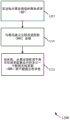
At block 1215, the UE115 may receive a responsive message from the base station indicating that at least one Data Radio Bearer (DRB) in the set of bearers will not be established. In this way, the indicated DRB (and corresponding EPS bearer) may be suspended.
Fig. 13 is a flow diagram illustrating a method 1300 for wireless communication that may be implemented subsequent to the method of fig. 11 in accordance with various aspects of the present disclosure. In particular, the method 1300 may transition a UE or apparatus from a first service type using fewer bearers to a second service type using more bearers. For clarity of illustration, the method 1300 is described below with reference to aspects of the UE115 described by fig. 1, 5, and/or 8, and/or the apparatus 115 described by fig. 7A and/or 7B. In some implementations, the UE or apparatus may execute one or more sets of codes to control the functional elements of the UE or apparatus to perform the functions described below.
First, the UE115 may be configured for D2D communication, such as described with reference to fig. 2, 10, and/or 11. At block 1305, the UE115 may identify uplink data (e.g., uplink communications via the base station) to be transmitted over the second service type.
At block 1310, the UE115 may transmit a second ESR, which may be triggered by identification of uplink data. As described above, the second ESR may indicate a second service type (which is different from the D2D communication service type) and may include an EPS bearer context state IE indicating a different subset of bearers to remain active.
At block 1315, the UE115 may receive a second message to establish at least one radio bearer in response to the second ESR. Each radio bearer may correspond to a respective EPS bearer that will be active as indicated by the second EPS bearer context state IE.
At block 1320, the UE115 may activate each respective EPS bearer for which its respective radio bearer is established from suspension. Thus, the UE115 may manage the bearers depending on the current service type used.
Fig. 14 is a flow diagram illustrating a method 1400 for wireless communication that may be implemented after the method of fig. 12 in accordance with various aspects of the present disclosure. In particular, the method 1400 may transition a UE or apparatus from a first service type that uses fewer bearers to a second service type that uses more bearers. For clarity of illustration, the method 1400 is described below with reference to aspects of the UE115 described by fig. 1, 4, and/or 8, and/or the apparatus 115 described by fig. 7A and/or 7B. In some implementations, the UE or apparatus may execute one or more sets of codes to control the functional elements of the UE or apparatus to perform the functions described below.
First, the UE115 may be configured for D2D communication, such as described with reference to fig. 3, 10, and/or 12. At block 1405, the UE115 may identify uplink data (e.g., uplink communications via the base station) to be transmitted over the second service type.
At block 1410, the UE115 may send a communication to request a resource allocation for uplink data. At block 1415, the UE115 may receive a second message in response to the communication (block 1410), wherein the second message indicates at least one DRB in the set of bearers for the uplink data.
At block 1420, the UE115 may configure the indicated at least one DRB and may activate each respective EPS bearer with its respective radio bearer configured from suspension. Thus, the UE115 may manage the bearers according to the current service type used.
Fig. 15 is a flow diagram illustrating another method 1400 for wireless communication that may be implemented after the method of fig. 11 or 12 in accordance with various aspects of the present disclosure. In particular, the method 1500 may transition a UE or apparatus from a first service type that uses fewer bearers to a second service type that uses more bearers. For clarity of illustration, the method 1500 is described below with reference to aspects of the UE115 described by fig. 1, 5, 6, and/or 8, and/or the apparatus 115 described by fig. 7A and/or 7B. In some implementations, the UE or apparatus may execute one or more sets of codes to control the functional elements of the UE or apparatus to perform the functions described below.
First, the UE115 may be configured for D2D communication, such as described with reference to fig. 2, 3, 10, 11, and/or 12. At block 1505, the UE115 may receive a second message when downlink data for the UE is pending (e.g., at the S-GW 535 in fig. 5 or the eNB 625 in fig. 6).
At block 1510, the UE115 may configure at least one DRB to support reception of downlink data. Where the UE is initially configured according to the method of fig. 12, the second message received at block 1505 may indicate at least one DRB in the set of bearers for the downlink data. Thus, in this case, the UE115 may configure the indicated at least one DRB at block 1510.
Where the UE is initially configured according to the method of fig. 11, the second message received at block 1505 may indicate at least one EPS bearer in the set of bearers for the pending downlink data. Accordingly, in this case, the UE115 may configure at least one DRB corresponding to the indicated at least one EPS bearer.
Alternatively, where the UE is initially configured according to the method of fig. 11, the UE115 may send the second ESR in response to the second message received at block 1505. Thus, in this case, the UE115 may configure the DRB and locally activate the suspended EPS bearer as indicated in the second ESR.
The detailed description set forth above in connection with the appended drawings describes some exemplary embodiments, but it is not intended that these embodiments be implemented, nor that they fall within the scope of the claims. The term "exemplary" used throughout this specification means "serving as an example, instance, or illustration," and does not mean "preferred" or "advantageous" over other embodiments. The detailed description includes specific details for the purpose of providing a thorough understanding of the described technology. However, the techniques may be practiced without these specific details. In some instances, well-known structures and devices are shown in block diagram form in order to avoid obscuring the concepts of the described embodiments.
Information and signals may be represented using any of a variety of different technologies and techniques. For example, data, instructions, commands, information, signals, bits, symbols, and chips that may be referenced throughout the above description may be represented by voltages, currents, electromagnetic waves, magnetic fields or particles, optical fields or particles, or any combination thereof.
The techniques described herein may be used for various wireless communication systems such as CDMA, TDMA, FDMA, OFDMA, SC-FDMA and other systems. The terms "system" and "network" are often used interchangeably. A CDMA system may implement a radio technology such as CDMA2000, Universal Terrestrial Radio Access (UTRA), and so on. CDMA2000 covers IS-2000, IS-95 and IS-856 standards. IS-2000 releases 0 and A are commonly referred to as CDMA 20001X, 1X, etc. IS-856(TIA-856) IS commonly referred to as CDMA 20001 xEV-DO, High Rate Packet Data (HRPD), and so on. UTRA includes wideband CDMA (wcdma) and other CDMA variations. TDMA systems may implement wireless technologies such as global system for mobile communications (GSM). The OFDMA system may implement wireless technologies such as Ultra Mobile Broadband (UMB), evolved UTRA (E-UTRA), IEEE 802.11(Wi-Fi), IEEE 802.16(WiMAX), IEEE 802.20, Flash-OFDM, and so on. UTRA and E-UTRA are part of the Universal Mobile Telecommunications System (UMTS). 3GPP Long Term Evolution (LTE) and LTE-advanced (LTE-A) are new versions of UMTS that employ E-UTRA. UTRA, E-UTRA, UMTS, LTE-A, and GSM are described in documents from an organization named "third Generation partnership project" (3 GPP). CDMA2000 and UMB are described in documents from an organization named "third generation partnership project 2" (3GPP 2). The techniques described herein may be used for the above-mentioned systems and wireless techniques, as well as other systems and wireless techniques. However, the following description describes an LTE system for exemplary purposes only, and LTE terminology is used in much of the description below, but these techniques are applicable outside of LTE applications.
The various illustrative blocks and modules described in connection with the disclosure herein may be implemented or performed with a general purpose processor, a Digital Signal Processor (DSP), an Application Specific Integrated Circuit (ASIC), a Field Programmable Gate Array (FPGA) or other programmable logic device, discrete gate or transistor logic, discrete hardware components, or any combination thereof designed to perform the functions described herein. A general-purpose processor may be a microprocessor, but in the alternative, the processor may be any conventional processor, controller, microcontroller, or state machine. A processor may also be implemented as a combination of computing devices (e.g., a combination of a DSP and a microprocessor, a number of microprocessors, one or more microprocessors in conjunction with a DSP core, or any other such configuration.
The functions described herein may be implemented in hardware, software executed by a processor, firmware, or any combination thereof. When implemented in software executed by a processor, the functions may be stored on or transmitted over as one or more instructions or code on a computer-readable medium. Other examples and implementations are within the scope and spirit of the disclosure and the following claims. For example, due to the nature of software, the functions described above may be implemented using software executed by a processor, hardware, firmware, hardware wiring, or any combination thereof. Further, features used to implement functionality may be physically located at multiple locations, including being distributed such that portions of functionality are implemented at different physical locations. Further, as used herein (which is included in the claims), the term "or" (e.g., a list of items prefaced by a term such as "at least one of or" one or more of) as used in a list of items indicates a separate list, such that, for example, the list "A, B or at least one of C" means: a or B or C or AB or AC or BC or ABC (i.e., A and B and C).
Computer-readable media includes both computer storage media and communication media including any medium that facilitates transfer of a computer program from one place to another. A storage media may be any available media that can be accessed by a general purpose or special purpose computer. By way of example, and not limitation, computer-readable media can comprise RAM, ROM, EEPROM, CD-ROM or other optical disk storage, magnetic disk storage or other magnetic storage devices, or any other medium that can be used to carry or store desired program code means in the form of instructions or data structures and that can be accessed by a general-purpose or special-purpose computer, or a general-purpose or special-purpose processor. Further, any connection is properly termed a computer-readable medium. For example, if the software is transmitted from a website, server, or other remote source using a coaxial cable, fiber optic cable, twisted pair, Digital Subscriber Line (DSL), or wireless technologies such as infrared, radio, and microwave, then the coaxial cable, fiber optic cable, twisted pair, DSL, or wireless technologies such as infrared, radio, and microwave are included in the definition of medium. Disk and disc, as used herein, includes Compact Disc (CD), laser disc, optical disc, Digital Versatile Disc (DVD), floppy disk and blu-ray disc where disks usually reproduce data magnetically, while discs reproduce data optically with lasers. Combinations of the above are also included within the scope of computer-readable media.
The previous description of the disclosure is provided to enable any person skilled in the art to make or use the disclosure. Various modifications to the disclosure will be readily apparent to those skilled in the art, and the generic principles defined herein may be applied to other variations without departing from the spirit or scope of the disclosure. The terms "example" or "exemplary" throughout this disclosure indicate an example or instance, and are not intended to imply or require any preference for the stated example. Thus, the disclosure is not intended to be limited to the examples and designs described herein but is to be accorded the widest scope consistent with the principles and novel features disclosed herein.
Claims (28)
1. A method for wireless communication, comprising:
transmitting, from a User Equipment (UE), a connection request indicating a service type and including an Information Element (IE);
establishing a bearing set; and
suspending at least one bearer in the set of bearers, the at least one suspended bearer being indicated by the IE and being based at least in part on the indicated service type;
wherein the connection request comprises:
an Extended Service Request (ESR) indicating the service type, and wherein the IE comprises an Evolved Packet System (EPS) bearer context state IE indicating a subset of EPS bearers of the set of bearers that are to be active.
2. The method of claim 1, wherein the connection request indicates that the service type is a device-to-device (D2D) communication.
3. The method of claim 1, wherein the connection request indicates that the type of service is machine-to-machine communication.
4. The method of claim 1, further comprising:
receiving, at the UE, a message in response to the ESR for establishing at least one radio bearer corresponding to a respective EPS bearer in the subset that will be active as indicated by the EPS bearer context state IE; and
wherein suspending comprises locally suspending each EPS bearer in the set of bearers for which no corresponding radio bearer is established.
5. The method of claim 4, further comprising:
sending, from the UE, a second ESR indicating a second service type and including a second EPS bearer context state IE indicating a second subset of EPS bearers of the set of bearers that are to be active;
receiving, at the UE, a second message in response to the second ESR for establishing at least one radio bearer, each radio bearer corresponding to a respective EPS bearer indicated by the second EPS bearer context state IE to be active; and
each respective EPS bearer, for which its corresponding radio bearer is to be established, is activated from suspension.
6. The method of claim 5, further comprising:
identifying uplink data to be transmitted with the second service type to trigger transmitting the second ESR.
7. The method of claim 6, wherein identifying uplink data to be transmitted over the second service type comprises:
a Radio Resource Control (RRC) error is identified.
8. The method of claim 5, further comprising:
sending a communication from the UE to activate all EPS bearers in the set of bearers when data is to be sent from the UE over a second service type.
9. The method of claim 8, wherein sending the communication to activate all EPS bearers in the set of bearers comprises:
a Tracking Area Update (TAU) request is sent.
10. The method of claim 8, further comprising:
receiving, at the UE, a second message in response to the communication; and
activating each locally suspended EPS bearer based at least in part on the second message.
11. The method of claim 4, further comprising:
receiving, at the UE, a second message when downlink data for the UE is pending;
transmitting, from the UE, a second ESR in response to the second message; and
activating each locally suspended EPS bearer as indicated in the second ESR.
12. The method of claim 4, further comprising:
receiving, at the UE, a second message indicating at least one EPS bearer in the set of bearers for the pending downlink data when the downlink data for the UE is pending; and
configuring at least one Data Resource Bearer (DRB) corresponding to the indicated at least one EPS bearer.
13. The method of claim 1, wherein the connection request comprises:
a Service Request (SR) indicating the service type.
14. The method of claim 13, further comprising:
establishing a Radio Resource Control (RRC) connection with the base station based at least in part on the indicated type of service; and
receiving, at the UE, a message from the base station indicating that at least one Data Radio Bearer (DRB) in the set of bearers will not be established, thereby suspending the at least one DRB.
15. The method of claim 14, further comprising:
configuring a virtual Packet Data Convergence Protocol (PDCP) and a virtual Radio Link Control (RLC) based at least in part on the received message.
16. The method of claim 14, further comprising:
identifying uplink data to be transmitted through the second service type; and
transmitting, from the UE, a communication for requesting resource allocation;
receiving, at the UE, a second message indicating at least one DRB in the set of bearers for the uplink data; and
configuring the indicated at least one DRB.
17. The method of claim 16, wherein identifying uplink data to be transmitted over the second service type comprises:
a Radio Resource Control (RRC) error is identified.
18. The method of claim 14, further comprising:
receiving, at the UE, a second message indicating at least one DRB in the set of bearers for the downlink data when the downlink data for the UE is pending; and
configuring the indicated at least one DRB.
19. An apparatus for wireless communication, comprising:
means for transmitting, from a User Equipment (UE), a connection request indicating a service type and including an Information Element (IE);
means for establishing a set of bearers; and
means for suspending at least one bearer in the set of bearers, the at least one suspended bearer being indicated by the IE and being based at least in part on the indicated service type;
wherein the connection request comprises:
an Extended Service Request (ESR) indicating the service type, and wherein the IE comprises an Evolved Packet System (EPS) bearer context state IE indicating a subset of EPS bearers of the set of bearers that are to be active.
20. The apparatus of claim 19, wherein the connection request indicates that the service type is a device-to-device (D2D) communication.
21. A method for wireless communication, comprising:
receiving, at a base station, a connection request indicating a service type and including an Information Element (IE);
establishing a bearing set; and
suspending at least one bearer in the set of bearers, the at least one suspended bearer being indicated by the IE and being based at least in part on the indicated service type;
wherein the connection request comprises:
an Extended Service Request (ESR) indicating the service type, and wherein the IE comprises an Evolved Packet System (EPS) bearer context state IE indicating a subset of EPS bearers of the set of bearers that are to be active.
22. The method of claim 21, wherein the connection request indicates that the service type is a device-to-device (D2D) communication.
23. The method of claim 21, wherein the connection request comprises:
a Service Request (SR) indicating the service type.
24. The method of claim 23, further comprising:
establishing a Radio Resource Control (RRC) connection with a User Equipment (UE) based at least in part on the indicated type of service; and
sending a message to the UE indicating that at least one Data Radio Bearer (DRB) in the set of bearers will not be established, thereby suspending the at least one DRB.
25. The method of claim 21, further comprising:
sending, from the base station to a Mobility Management Entity (MME), a message in response to the received connection request, the message indicating which bearers of the set of bearers are to be suspended by the MME.
26. An apparatus for wireless communication, comprising:
means for receiving, at a base station, a connection request indicating a service type and including an Information Element (IE);
means for establishing a set of bearers; and
means for suspending at least one bearer in the set of bearers, the at least one suspended bearer being indicated by the IE and being based at least in part on the indicated service type;
wherein the connection request comprises:
an Extended Service Request (ESR) indicating the service type, and wherein the IE comprises an Evolved Packet System (EPS) bearer context state IE indicating a subset of EPS bearers of the set of bearers that are to be active.
27. The apparatus of claim 26, wherein the connection request indicates that the service type is a device-to-device (D2D) communication.
28. The apparatus of claim 26, further comprising:
means for receiving, at a base station, a Radio Resource Control (RRC) connection manager of the connection request indicating the service type.
Applications Claiming Priority (5)
| Application Number | Priority Date | Filing Date | Title |
|---|---|---|---|
| US201462024502P | 2014-07-15 | 2014-07-15 | |
| US62/024,502 | 2014-07-15 | ||
| US14/794,010 | 2015-07-08 | ||
| US14/794,010 US10433284B2 (en) | 2014-07-15 | 2015-07-08 | Bearer management for prose direct discovery |
| PCT/US2015/039655 WO2016010804A1 (en) | 2014-07-15 | 2015-07-09 | Bearer management for prose direct discovery |
Publications (2)
| Publication Number | Publication Date |
|---|---|
| CN107113535A CN107113535A (en) | 2017-08-29 |
| CN107113535B true CN107113535B (en) | 2020-06-05 |
Family
ID=55075786
Family Applications (1)
| Application Number | Title | Priority Date | Filing Date |
|---|---|---|---|
| CN201580038061.XA Active CN107113535B (en) | 2014-07-15 | 2015-07-09 | Bearer management for PROS direct discovery |
Country Status (7)
| Country | Link |
|---|---|
| US (1) | US10433284B2 (en) |
| EP (1) | EP3170359B1 (en) |
| JP (1) | JP6563476B2 (en) |
| KR (1) | KR20170032297A (en) |
| CN (1) | CN107113535B (en) |
| BR (1) | BR112017000188A2 (en) |
| WO (1) | WO2016010804A1 (en) |
Families Citing this family (10)
| Publication number | Priority date | Publication date | Assignee | Title |
|---|---|---|---|---|
| CN106664700A (en) * | 2014-09-25 | 2017-05-10 | 夏普株式会社 | Latency reduction for mode switching in sidelink communications |
| WO2016185758A1 (en) * | 2015-05-15 | 2016-11-24 | 株式会社Nttドコモ | User equipment and the base station |
| KR102447859B1 (en) * | 2016-04-26 | 2022-09-27 | 삼성전자 주식회사 | Method and apparatus of supporting handover in wireless communication system |
| US11076442B2 (en) * | 2016-09-28 | 2021-07-27 | Lg Electronics Inc. | Method and apparatus for controlling SRB |
| US11057753B2 (en) * | 2016-10-07 | 2021-07-06 | Lg Electronics Inc. | Method and device for performing V2X communication |
| US11140732B2 (en) * | 2017-04-02 | 2021-10-05 | Lg Electronics Inc. | Method for performing sidelink communication in wireless communication system and apparatus therefor |
| CN110035422B (en) * | 2018-01-12 | 2021-01-22 | 大唐移动通信设备有限公司 | Uplink data processing method based on temporary processing tunnel table, MME and SGW |
| US11218282B2 (en) * | 2018-06-08 | 2022-01-04 | Qualcomm Incorporated | Fast activation and deactivation for low latency communications |
| CN111417215B (en) * | 2019-01-08 | 2022-04-22 | 华为技术有限公司 | Configuration method of radio bearer, terminal and communication device |
| US11277880B2 (en) * | 2019-02-14 | 2022-03-15 | Lg Electronics Inc. | Sidelink connection suspension or release based on different target qualities of different services |
Family Cites Families (17)
| Publication number | Priority date | Publication date | Assignee | Title |
|---|---|---|---|---|
| JP2011044804A (en) * | 2009-08-19 | 2011-03-03 | Panasonic Corp | Radio communication apparatus and radio communication method |
| WO2011052136A1 (en) * | 2009-10-30 | 2011-05-05 | Panasonic Corporation | Communication system and apparatus for status dependent mobile services |
| US9143461B2 (en) | 2010-04-30 | 2015-09-22 | Panasonic Intellectual Property Corporation Of America | Communication device, network node, and communication server |
| KR101598261B1 (en) * | 2010-09-20 | 2016-02-26 | 블랙베리 리미티드 | Methods and apparatus to provide packet switched service continuity during circuit switched fallback operation |
| CA2816153C (en) * | 2010-09-28 | 2017-08-08 | Research In Motion Limited | Residential/enterprise network connection management and csfb scenarios |
| KR20130079564A (en) * | 2010-09-28 | 2013-07-10 | 리서치 인 모션 리미티드 | Method and apparatus for releasing connection with local gw when ue moves out of the residential/enterprise network coverage |
| KR101561474B1 (en) * | 2010-12-23 | 2015-10-20 | 한국전자통신연구원 | Method of transmitting small amount of up-link data and method of receiving small amount of up-link data |
| US20130083646A1 (en) * | 2011-09-30 | 2013-04-04 | Renesas Mobile Corporation | Methods and Apparatus for Managing Resource Access Attempts |
| CN104641682B (en) * | 2011-10-28 | 2019-01-15 | 黑莓有限公司 | The method and apparatus of carrying are handled during circuit switched fallback operation |
| GB2489545B (en) * | 2011-11-29 | 2013-05-29 | Renesas Mobile Corp | Method, apparatus and computer program for establishing an emergency service |
| US9210630B2 (en) * | 2012-01-25 | 2015-12-08 | Lg Electronics Inc. | Method of transmitting a signal related to mobility management in a network supporting a number of network modes of operation |
| CN104521157B (en) * | 2012-07-20 | 2019-02-15 | Lg 电子株式会社 | Method and apparatus of the sending device to device-dependent information in a wireless communication system |
| JP2015534355A (en) | 2012-09-14 | 2015-11-26 | インターデイジタル パテント ホールディングス インコーポレイテッド | Mobility control method for performing Wi-Fi offloading in a wireless system |
| WO2014185708A1 (en) * | 2013-05-14 | 2014-11-20 | Samsung Electronics Co., Ltd. | System and method for ip session continuity in device-to-device communication system |
| WO2015163626A1 (en) * | 2014-04-24 | 2015-10-29 | Lg Electronics Inc. | Method for releasing a sidelink radio bearer for d2d communication system and device therefor |
| US20170041818A1 (en) * | 2014-04-25 | 2017-02-09 | Lg Electronics Inc. | Method for a configuration error management for a sidelink radio bearer and device therefor |
| WO2015195014A1 (en) * | 2014-06-19 | 2015-12-23 | Telefonaktiebolaget L M Ericsson (Publ) | Method and arrangement for handling radio resources |
-
2015
- 2015-07-08 US US14/794,010 patent/US10433284B2/en active Active
- 2015-07-09 BR BR112017000188A patent/BR112017000188A2/en active Search and Examination
- 2015-07-09 EP EP15739465.1A patent/EP3170359B1/en active Active
- 2015-07-09 WO PCT/US2015/039655 patent/WO2016010804A1/en active Application Filing
- 2015-07-09 KR KR1020177001025A patent/KR20170032297A/en active IP Right Grant
- 2015-07-09 CN CN201580038061.XA patent/CN107113535B/en active Active
- 2015-07-09 JP JP2017502099A patent/JP6563476B2/en active Active
Also Published As
| Publication number | Publication date |
|---|---|
| WO2016010804A1 (en) | 2016-01-21 |
| US10433284B2 (en) | 2019-10-01 |
| EP3170359B1 (en) | 2019-02-13 |
| BR112017000188A2 (en) | 2017-10-31 |
| EP3170359A1 (en) | 2017-05-24 |
| JP2017521953A (en) | 2017-08-03 |
| JP6563476B2 (en) | 2019-08-21 |
| KR20170032297A (en) | 2017-03-22 |
| CN107113535A (en) | 2017-08-29 |
| US20160021649A1 (en) | 2016-01-21 |
Similar Documents
| Publication | Publication Date | Title |
|---|---|---|
| CN107113535B (en) | Bearer management for PROS direct discovery | |
| EP3603316B1 (en) | Mechanisms for establishing user plane connectivity for non-3gpp access | |
| EP3603195B1 (en) | User plane relocation techniques in wireless communication systems | |
| EP3219168B1 (en) | Enhanced connection management for multiple access networks | |
| KR102335693B1 (en) | Methods and apparatuses for NR PDCP preservation in RRC resume/suspend | |
| US11284468B2 (en) | Suspending/resuming measurements in RRC inactive state | |
| CN106576235B (en) | Method, apparatus and computer readable medium for device-to-device capability signaling | |
| EP3146793B1 (en) | Modem assisted contention handling of multiple active connections in wireless communications | |
| US11115880B2 (en) | Path switch method between LTE and 5G node | |
| US20110194533A1 (en) | Method of Handling Radio Resource Reconfiguration | |
| WO2021067149A1 (en) | Systems and methods for managing radio bearer compatibility in a communication network | |
| EP3427513B1 (en) | Efficient transition between a trusted wlan and a wwan | |
| EP2357873A1 (en) | Method of handling radio resource reconfiguration | |
| CN116391446A (en) | Secondary cell group activation/deactivation in split node architecture | |
| WO2022271768A1 (en) | Managing paging for a user device | |
| BR112017009736B1 (en) | IMPROVED CONNECTION MANAGEMENT FOR MULTIPLE ACCESS NETWORKS |
Legal Events
| Date | Code | Title | Description |
|---|---|---|---|
| PB01 | Publication | ||
| PB01 | Publication | ||
| SE01 | Entry into force of request for substantive examination | ||
| SE01 | Entry into force of request for substantive examination | ||
| GR01 | Patent grant | ||
| GR01 | Patent grant |