CN107113492B - Method and apparatus for providing customized sound distribution - Google Patents
Method and apparatus for providing customized sound distribution Download PDFInfo
- Publication number
- CN107113492B CN107113492B CN201580054662.XA CN201580054662A CN107113492B CN 107113492 B CN107113492 B CN 107113492B CN 201580054662 A CN201580054662 A CN 201580054662A CN 107113492 B CN107113492 B CN 107113492B
- Authority
- CN
- China
- Prior art keywords
- sound
- array
- loudspeaker
- acoustic
- speaker
- Prior art date
- Legal status (The legal status is an assumption and is not a legal conclusion. Google has not performed a legal analysis and makes no representation as to the accuracy of the status listed.)
- Active
Links
Images


Classifications
-
- H—ELECTRICITY
- H04—ELECTRIC COMMUNICATION TECHNIQUE
- H04R—LOUDSPEAKERS, MICROPHONES, GRAMOPHONE PICK-UPS OR LIKE ACOUSTIC ELECTROMECHANICAL TRANSDUCERS; DEAF-AID SETS; PUBLIC ADDRESS SYSTEMS
- H04R1/00—Details of transducers, loudspeakers or microphones
- H04R1/02—Casings; Cabinets ; Supports therefor; Mountings therein
- H04R1/023—Screens for loudspeakers
-
- H—ELECTRICITY
- H04—ELECTRIC COMMUNICATION TECHNIQUE
- H04R—LOUDSPEAKERS, MICROPHONES, GRAMOPHONE PICK-UPS OR LIKE ACOUSTIC ELECTROMECHANICAL TRANSDUCERS; DEAF-AID SETS; PUBLIC ADDRESS SYSTEMS
- H04R1/00—Details of transducers, loudspeakers or microphones
- H04R1/20—Arrangements for obtaining desired frequency or directional characteristics
- H04R1/32—Arrangements for obtaining desired frequency or directional characteristics for obtaining desired directional characteristic only
- H04R1/40—Arrangements for obtaining desired frequency or directional characteristics for obtaining desired directional characteristic only by combining a number of identical transducers
- H04R1/403—Arrangements for obtaining desired frequency or directional characteristics for obtaining desired directional characteristic only by combining a number of identical transducers loud-speakers
-
- H—ELECTRICITY
- H04—ELECTRIC COMMUNICATION TECHNIQUE
- H04R—LOUDSPEAKERS, MICROPHONES, GRAMOPHONE PICK-UPS OR LIKE ACOUSTIC ELECTROMECHANICAL TRANSDUCERS; DEAF-AID SETS; PUBLIC ADDRESS SYSTEMS
- H04R3/00—Circuits for transducers, loudspeakers or microphones
- H04R3/04—Circuits for transducers, loudspeakers or microphones for correcting frequency response
-
- H—ELECTRICITY
- H04—ELECTRIC COMMUNICATION TECHNIQUE
- H04R—LOUDSPEAKERS, MICROPHONES, GRAMOPHONE PICK-UPS OR LIKE ACOUSTIC ELECTROMECHANICAL TRANSDUCERS; DEAF-AID SETS; PUBLIC ADDRESS SYSTEMS
- H04R5/00—Stereophonic arrangements
- H04R5/02—Spatial or constructional arrangements of loudspeakers
-
- H—ELECTRICITY
- H04—ELECTRIC COMMUNICATION TECHNIQUE
- H04S—STEREOPHONIC SYSTEMS
- H04S7/00—Indicating arrangements; Control arrangements, e.g. balance control
- H04S7/30—Control circuits for electronic adaptation of the sound field
- H04S7/302—Electronic adaptation of stereophonic sound system to listener position or orientation
- H04S7/303—Tracking of listener position or orientation
-
- H—ELECTRICITY
- H04—ELECTRIC COMMUNICATION TECHNIQUE
- H04R—LOUDSPEAKERS, MICROPHONES, GRAMOPHONE PICK-UPS OR LIKE ACOUSTIC ELECTROMECHANICAL TRANSDUCERS; DEAF-AID SETS; PUBLIC ADDRESS SYSTEMS
- H04R2201/00—Details of transducers, loudspeakers or microphones covered by H04R1/00 but not provided for in any of its subgroups
- H04R2201/40—Details of arrangements for obtaining desired directional characteristic by combining a number of identical transducers covered by H04R1/40 but not provided for in any of its subgroups
- H04R2201/401—2D or 3D arrays of transducers
-
- H—ELECTRICITY
- H04—ELECTRIC COMMUNICATION TECHNIQUE
- H04R—LOUDSPEAKERS, MICROPHONES, GRAMOPHONE PICK-UPS OR LIKE ACOUSTIC ELECTROMECHANICAL TRANSDUCERS; DEAF-AID SETS; PUBLIC ADDRESS SYSTEMS
- H04R2203/00—Details of circuits for transducers, loudspeakers or microphones covered by H04R3/00 but not provided for in any of its subgroups
- H04R2203/12—Beamforming aspects for stereophonic sound reproduction with loudspeaker arrays
-
- H—ELECTRICITY
- H04—ELECTRIC COMMUNICATION TECHNIQUE
- H04S—STEREOPHONIC SYSTEMS
- H04S5/00—Pseudo-stereo systems, e.g. in which additional channel signals are derived from monophonic signals by means of phase shifting, time delay or reverberation
Landscapes
- Physics & Mathematics (AREA)
- Engineering & Computer Science (AREA)
- Acoustics & Sound (AREA)
- Signal Processing (AREA)
- Health & Medical Sciences (AREA)
- Otolaryngology (AREA)
- Circuit For Audible Band Transducer (AREA)
- Obtaining Desirable Characteristics In Audible-Bandwidth Transducers (AREA)
- Stereophonic System (AREA)
Abstract
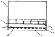
A loudspeaker system for providing tailored acoustic wavefronts having vertical and horizontal pattern control and amplitude and phase control, said system comprising a loudspeaker enclosure (1) with at least a first array (2) of high frequency driver segments (3) and at least a second array (4) of low frequency driver segments (5) disposed behind said first array (2), said first array having sufficient space between said driver segments (3) to allow acoustic transparency so that wavefronts from said second array (4) can reasonably pass through said first array (2).
Description
Technical Field
The present invention relates to sound systems, and in particular, but not exclusively, the present invention discloses an apparatus for providing a tailored spatial distribution of sound and a method of controlling the spatial distribution of such an apparatus to handle various listening situations.
Background
To maximize sound quality, it is currently known to provide dual (with separate high and low frequency drives) and more-way loudspeakers with static (or mechanical) control of the sound or dynamic control of a single dimension of the sound dispersion parameter (typically the vertical dimension, but rotation of the loudspeaker can change this single dimension to correlate with the horizontal dimension). However, the dispersion angle in the second dimension (typically the horizontal dimension) is currently limited by the built-in mechanical (static or fixed) parameters of the dual-channel speaker. In addition, the high frequency drive in conventional prior art dual loudspeakers is only located beside or above the low frequency drive in a single line. These mechanical limitations only allow conventional two-way speakers to be enlarged and adapted in only a single dimension.
In some cases, a two-dimensional set of limited bandwidth drivers may be used as a one-way speaker; however, this technique does not support high fidelity full bandwidth audio due to the compromise in drive size and drive performance. Thus, prior art audio systems are unable to provide a controlled dynamically adapted two-dimensional wavefront (wavefront) across vertical and horizontal planes over the entire audio bandwidth, including high and low frequencies.
In the case of sending differential control signals to individual speakers of a multi-drive system, conventional prior art may include:
(i) the sound direction is changed by applying a linearly varying delay to the loudspeaker array,
(ii) focusing or defocusing the sound by applying a quadratically varying delay to the loudspeaker array, and
(iii) an approximate sound distribution is heuristically achieved by manually varying parameters of the plurality of individual loudspeakers.
Under far field constraints, the acoustic wave equation reduces to a fourier transform.
In this case, it can be seen that the change in direction is achieved by the fourier shift characteristic

Wherein, λ is the wavelength of sound,
s-sin (θ)/λ (θ is the angular maintenance of the speaker normal),
a is the linear delay (defined as the sine of the deflection angle), and
f is the fourier transform of F:

focusing (defocusing) is achieved by applying equal phase of the fresnel lens with focal length b:

however, these three methods (i, i, and iii) are insufficient for most environments where natural asymmetry exists, such as auditoriums or gymnasiums. Other techniques are therefore needed. Fourier transforms can be used, but this is often not enough due to delay ambiguity at the listener. This means that there is no unique solution, but many; this problem extends to determining which is the best (schemes usually specify the attenuation of individual loudspeakers, thus losing the efficiency of using all available energy, and also taking into account the frequency dependence since s is a function of λ).
Disclosure of Invention
According to one aspect of the invention, a loudspeaker system is disclosed for providing tailored acoustic wavefronts with vertical and horizontal pattern control and amplitude and phase control, the system comprising a loudspeaker enclosure having at least a first array of high frequency driver segments (tweeters) and at least a second array of low frequency driver segments (woofers) disposed behind the first array, the driver segments of the first array having sufficient space therebetween to allow acoustic transparency so that wavefronts from the second array can pass through the first array.
According to one aspect of the present invention, there is disclosed a method of extending the above-described methods of changing direction and focus (i and ii) to further comprise changing the asymmetry of the sound distribution. This also uses the delay applied to the loudspeaker array.
In particular, a method is disclosed that includes an initial step of providing linear and quadratic delays according to equations (1) and (3) to change the direction of a beam or its propagation. Subsequently, the delay according to equation (4) is applied to change the asymmetry.

Equation (4) takes advantage of the properties of the function of the subrational (air function) whose fourier transform is in the form of a cubic phase term. The effect of adding a cubic delay thus causes a convolution of the subtree function in the far field: a deflection is introduced in the distribution of the sound accordingly. The uniqueness of the subrational function and the Dirac distribution (Dirac distribution) in the algebraic transformation of the phase functions makes it more straightforward to model their behavior.
According to yet another aspect of the invention, a method of calculating an additional delay to be applied to a loudspeaker of an array is disclosed, wherein (in addition to linear, quadratic and cubic terms) the components of the delay are determined as a series of fourier's to smooth ripples in the spatial variation of the sound distribution and/or to improve the frequency dependent coherence of the sound distribution.
The phase term, combined with the cosine term as an example, is given by:

where Δ is the amplitude of a particular periodic function and Λ is its period. Where the delay is the negative of the term in brackets. The Fourier transform of equation (5) is as follows:

where is a dirac trigonometric function which is equal to 1 when the variable is zero and 0 when the variable is not zero. This is seen as producing additional harmonics of the spatial distribution that are offset by the following angles:

the series of Fourier transforms can be formed by selecting Λ such that θnThe half-cycles of any oscillation in the spatial distribution are matched for calculation based on an analysis of the spatial distribution of the acoustic wave. Λ is chosen to minimize oscillation. Such analysis may be performed by any harmonic analysis (e.g., fourier transform, short-time fast fourier transform, wavelet) and/or optimization technique to reduce higher frequency peaks in the energy spectrum (e.g., least mean square regression, simulated annealing).
According to yet another aspect of the invention, an audio speaker using the above method is disclosed, comprising a sound radiating surface with vertical and horizontal dimensions, said dimensions being defined by a plurality of discrete segments, each segment being associated with a respective single sound source providing a processed and amplified signal to generate amplitude and phase controlled horizontal and vertical sound patterns.
Preferably, the segment should be limited to ten wavelengths on the highest control frequency size. The optimum effect is obtained when the size of the segment is reduced to less than one wavelength.
Preferably, the signal processing comprises Digital Signal Processing (DSP) in the form of phase, delay, amplitude, Infinite Impulse Response (IIR) filter, Finite Impulse Response (FIR) filter processing.
More preferably, the method of controlling, DSP processing and amplifying is internal or external to the audio speaker.
More preferably, the distance between the outer edge of the sound source emitting surface in one segment and the outer edge of the sound source emitting surface in an adjacent segment is limited to ten wavelengths in distance of the highest frequency controlled by the segment. The optimum effect is obtained when the reduction is less than one quarter wavelength in distance of the highest frequency of the segment control.
More preferably, the frequency range produced by the loudspeaker is divided into one or more frequency bands by using band-limiting filters.
When more than one frequency band is used, each frequency band preferably meets the above criteria, forming a set of segments on the surface of the flat panel array. Each band-limited segment may be layered with respect to each other in three dimensions. Each layer of the band-limited segment can be processed discretely.
More preferably, each band limiting layer is sufficiently acoustically transparent above the other band limiting layer to allow the wavefront acoustics of a band limiting plate array to pass through any outer band limiting layer. To achieve acoustic transparency, a minimum perforation rate of 10% is preferred.
Drawings
A loudspeaker enclosure of a presently preferred embodiment of the invention will now be described with reference to the accompanying drawings, in which:
FIG. 1 is a cut-away perspective view of an audio speaker according to the present invention;
FIG. 2 is a side cross-sectional view of the assembled speaker of FIG. 1;
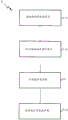
FIG. 3 is a block diagram depicting a preferred method of setting up a field floor system to accommodate the speakers;
fig. 4 is a block diagram depicting a preferred arrangement for continuous adaptation of the sound system.
Detailed Description
The loudspeaker of the present invention is described below for one unit. However, it will be appreciated by those skilled in the art that the loudspeaker of the present invention may be adapted such that a plurality of such loudspeakers are stacked vertically and horizontally to create a larger system.
Such a large system may be of any size and shape and is capable of producing one or more customized acoustic wavefronts having vertical and horizontal pattern control and amplitude and phase control. Although any size loudspeaker system according to the invention is capable of controlling the horizontal and vertical patterns and the amplitude and phase control below any selected low frequency limit, it is best when the vertical length or horizontal length of the large system is one wavelength longer than the length corresponding to the lowest frequency to be controlled.
The loudspeaker according to the invention is capable of producing a resultant asymmetric acoustic wavefront with vertical and horizontal pattern control and amplitude and phase control. As an economical alternative, a more cost-effective version of the invention can be produced by providing symmetrically opposed multiple sound sources from the same processing and amplification stage. This variation of the invention merely limits the invention to producing symmetrical customized acoustic wavefronts with vertical and horizontal pattern control and amplitude and phase control.
Referring to fig. 1, a two-way speaker system according to one embodiment of the present invention is shown. The loudspeaker system may comprise an aluminium enclosure (1) with a plurality of wire soft-dome (soft-dome) tweeters (3) (high frequency segments) of 22mm diameter (mm) on a stainless steel plate (2) that produce band limited sound of 1.5kHz-20 kHz. The plurality of 22mm diameter tweeters may be spaced apart vertically and horizontally by a pitch of 5.3cm, producing a motherboard array of 5 columns of 10 rows of 50 tweeters. The body dimensions of the loudspeaker are preferably 26.5cm wide by 53cm high with a total of 50 high frequency segments in the form of a tweeter array (3). Each silk soft hemispherical tweeter point source preferably has a mounting frame diameter of about 40 mm. Mounted below the high-frequency plate is an aluminum plate (4) which is mounted with a frame comprising 10 43/4"drive (5) (low frequency slice) secondary low frequency panel array, produce band limited sound of 20Hz-1.5 kHz. Each 4 is3/4The "low frequency drives are preferably vertically spaced about 106mm apart and horizontally spaced about 125mm apart. There are 10 low frequency segments in a given secondary plate array. The plurality of high frequency bands (3) have sufficient space between drives to allow about 54% acoustic transparency. An aluminum front trim (6) is provided. Each Low Frequency (LF) and High Frequency (HF) segment is fed by a sound source (not shown) into a unique, customized, computationally processed audio signal. Custom electronics and amplification provide unique signal processing for each LF and HF segment, preferably in the form of a 2 second delay, four biquad filter Infinite Impulse Response (IIR) filters, a 10 coefficient Finite Impulse Response (FIR) filter, a low pass filter, a high pass filter, and a pair outputThe amplitude control of (2). Two inputs may be provided, with unique processing and summing applied to each input before reaching each amplifier module. In this embodiment, there are preferably a total of 60 amplifier channels.
The above-described embodiments are capable of producing customized horizontal and vertical controlled wavefronts with amplitude and phased arrays, controlled at the operating band 20Hz-20 kHz. As will become apparent from the following description, the speaker system of the present invention is also capable of controlling vertical and horizontal patterns, as well as more complex two and three dimensional (three dimensions being horizontal axis, vertical axis and acoustic magnitude) wave fronts in both horizontal and vertical planes from 180 degrees to 1 degree. As will be discussed in detail below, the loudspeaker system is also capable of employing a "dual monitor mode" due to the nature of having two uniquely processed sound source inputs. The mode of operation of the loudspeaker is described below to provide a "live arena setup", "live arena operation", "live performer tracking", "three-dimensional panel array sound", "three-dimensional panel array cinema" integrated system.
On-site setting
At the venue where the audio is amplified and projected to the listener, the audio must be delivered to the listener in a manner sufficient to enhance the listening experience of the listener. In many cases, this is difficult to achieve due to the varying spacing between sites and the manner in which different sites are constructed.
The interaction between projected sound and the venue environment creates two unique problems for a venue:
1) the varying distance between the listener and the speaker. The change in distance translates into a change in sound pressure level.
2) Various surfaces that reflect sound. This is commonly referred to as room reverberation or sound reflections, which affect the sound quality. The less sound radiates towards the surface where there is no listener, the less room reverberation, the more natural the sound, and the higher the timbre.
With the "live floor setting" and the inventive loudspeaker system, the system can be set to fit a floor where sound is projected to optimize the listening experience of the listener at the floor.
As will be discussed in detail below, this is achieved by using conventional range finders and/or laser distance measuring devices which provide a simple means of electronically mapping the field to enable a computer to determine the distance to the plane of the listener (listener) in a three dimensional space which can be used to set up a loudspeaker system according to the invention.
By using the preferred mathematical model, a customized acoustic wavefront can be generated for the loudspeaker system to produce the best acoustic effect for the space, as described below. This may include reducing acoustic energy towards problematic acoustic surfaces within the space, limiting acoustic energy to locations only towards the listener, and optimizing sound pressure levels and other acoustic qualities to produce a more uniform experience across the auditorium.
As shown in fig. 3, the method 20 provides a live floor system to accommodate the speaker system of the present invention in preparation for a performance.
The method 20 comprises a first step 22 of obtaining environmental information of the venue on which the sound is to be projected. This step is performed using a commercially available laser range finder, such as Opti-logic RS800, mounted on a commercially available offset-tilt (pan-tilt) motorized mount, such as JEC J-PT-1205. Such laser rangefinders are typically provided with a computer interface, such as RS232, and may operate to minimally target non-emitting surfaces in the range of 10m to 30 m. The commercially available laser rangefinder on a tilt-tilt motorized mount is equipped with a small computer or microprocessor. Such a small computer can control the tilt-tilt motorized mount and read data from the laser rangefinder. In a preferred embodiment, the microcomputer may be a Raspberry Pi microcomputer with RS232 and RS485 interfaces for controlling the laser rangefinder and motorized mount.
In one embodiment of the method, a visible light laser may be configured to the entire system to allow visual feedback showing where the laser rangefinder is aimed. Alternatively, the viewfinder of the laser rangefinder may have a camera mounted thereon that can be viewed through a standard video link to a control interface. In a preferred embodiment, the camera is connected to the Rasberry Pi or similar microcomputer to provide video to the operator via a standard ethernet network link, either wireless or wired.
As part of the venue environment information obtained in step 22, the laser rangefinder with offset/tilt motorized mount may be located anywhere within the venue. But preferably the laser rangefinder is mounted on a support or suspension support that suspends (fly) the panel array loudspeaker system of the present invention or mounts the panel array loudspeaker system of the present invention at the site. In this way, the laser rangefinder can have the same viewing angle as the loudspeaker (loudspeaker), making the geometric calculation of the field simpler.
The Rasberry Pi or similar computer can be remotely controlled to automatically scan the local environment of the field, traversing the entire horizontal and inclined vertical extent of the field and transmitting distance measurements of a given resolution from the laser rangefinder to the mini-computer to produce a three-dimensional model of the room. From this model, a data array can be constructed that includes distance information for each horizontal and vertical resolution. The operator may then define the target area covered by the loudspeaker by manual input.
In a preferred embodiment, the operator can control the Rasberry Pi or similar computer via wireless ethernet. In this manner, an operator can remotely read the data from a remote operator location and initially determine a minimum of 4 boundary locations based on a three-dimensional model of the field. Nominally, these 4 positions are typically the right rear corner of the venue audience position, the left front corner of the venue audience position, and the right front corner of the venue audience position. It will be appreciated that for fields or listener positions having more complex shapes, such as circular or curved listener positions, more than 4 listener boundary positions may be set.
These 4 or more listener boundary positions provide the operator with coordinate input information to automatically adjust the offset and tilt positions of the motorized support. Vertical increments of 1 degree and horizontal increments of 1 degree are preferred, but other resolutions are possible. Reading the laser range finder after the motorized support is moved to a position, thereby constructing a data array for each vertical and horizontal position. This process is repeated until the entire area defined by the 4 or more boundary positions is covered according to the nominal resolution. Once the data array containing distance information relative to offset and tilt angle information is generated, the operator's necessary context information is generated, thereby completing step 22, wherein the offset and tilt information binds listener position.
At step 24, the operator must define inputs to the panel array loudspeaker system. Typically this requires the operator to define the type of speakers appropriate to the venue, which includes an assessment of the number of speakers required and the arrangement and location of the speakers within the venue.
After defining the loudspeaker requirements, general loudspeaker parameters can be determined, including the size, shape and spacing of the individual transducers (transducers) within the loudspeaker enclosure, step 26. The speaker parameters are generally known and may be obtained using a library of parameters provided by the speaker manufacturer. Knowing the type of speakers installed at the venue and the parameters of those speakers, an operator can calculate the best match of the panel array speaker parameters to optimize the listener experience for a particular venue. The optimal selection of the values a, b, the asymmetry of the irrational function, Δ and a can be achieved by (i) calculating only at the peaks and valleys of the spatial distribution, (ii) regression fitting at more data points, (iii) identifying the periodicity and amplitude of the spatial distribution using fourier analysis or (iv) using genetic algorithms/simulated annealing.
Once the optimized parameters for the panel array loudspeaker system are determined, the optimized parameters may be applied directly to the loudspeaker hardware by the operator, step 28. In this way, the panel array loudspeaker system can be optimally programmed by the operator to produce a multi-dimensional acoustic wavefront that best matches the shape of the audience and the distance of the listener of the venue, while allowing more acoustic energy to be located away from the non-audience locations identified in the three-dimensional map of the venue. This method of setting up a loudspeaker system for a venue results in a significant improvement in sound quality in the listener environment because reflections are removed as much as possible. In addition, the sound at the listener position is also optimized as far as possible in terms of hue characteristics and sound pressure level.
On-site field operations
Some venues may have an open space to accommodate the audience, but the audience may be concentrated in a portion of the space, while in other venues the audience may be scattered in a space. The less sound radiates to the surface without the listener, the less reverberation, the more natural the sound and the higher the timbre. Audience position and seating rate may be variable and variable throughout the course of an event in a venue.
It will be appreciated that the setup method 20 described above with reference to figure 3 provides a simple and effective means of adapting the loudspeaker system of the present invention to project sound on the field. However, the system of the present invention may also provide a continuous match of the sound system as the venue parameters change during an event. A method 30 of achieving this is depicted in fig. 4.
In step 31, the audience space of the venue is monitored during the event. This can be accomplished through the use of a live camera system and facial recognition software that can evaluate and determine the location of the listener in the venue. By monitoring changes in the listener's position, the customized acoustic wavefront for the loudspeaker system can be updated to define the space occupied by the acoustic energy such that it is oriented specifically. Such systems improve clarity and other acoustic properties by reducing acoustic energy towards unoccupied reflective surfaces.
As described in the method 20 of positioning speaker systems discussed above, commercially available camera systems are typically positioned to view the space covered by the panel array speakers. The camera may be located anywhere within the venue; however, the camera is preferably mounted on or near a loudspeaker mounting or suspension bracket from which the panel array loudspeaker system is suspended or mounted. In this way, the camera can have the same viewing angle as the loudspeaker, making the geometric calculations simpler.
Third party facial recognition software, which may be run on a computer system, provides a continuous analysis of the occupancy of the venue, which is the relative coordinates in plan view with respect to the horizontal and vertical positions of the loudspeakers. The preferred third party facial recognition software is the Cisco video surveillance system. In this regard, an operator can monitor the third party facial recognition software to read occupancy detection data as well as coordinate information. This information is then translated to update the listener boundary conditions in step 32.
At step 32, this audience boundary condition may be updated to the "field floor setup" module as described above. These new border positions refer to the already obtained array of information obtained by laser scanning or physical measurement at nominal resolution (typically 1 degree both horizontally and vertically) of the distance of each horizontal and vertical position within the new listener border position.
Once the data array is generated, the operator has the necessary context information, including distance information with respect to offset and tilt angle information, which binds listener position. At step 33 an evaluation is made to determine if the audience space boundary conditions have changed and if not, the system continues to monitor the audience space at step 31. However, if it is determined at step 33 that there has been a change in audience space and that the audience space boundaries have changed because of an increase in the number of listeners or a change in the setting of audience space, the system will seek to redefine the venue speaker requirements at step 34. At step 34, the operator must define inputs to the plate array system. This typically involves defining the type of speakers, number of speakers and arrangement of speakers that cover the nominal listener position. Other aspects of the loudspeaker, such as the size, shape and spacing of the individual transducers within the loudspeaker enclosure, may also be determined. In most cases, these aspects of the speaker can be known by using a parameter library published by the speaker manufacturer. At this step, it is contemplated that the operator manually enters the type of speakers used, the number of speakers, and how the speaker array is set.
Once all the environment and speaker inputs are known, the software can calculate the best match of the parameters of the panel array speaker system to the changing environment, step 35. Optimal selection of the values a, b, asymmetry of the irrational function, Δ and Λ can be achieved by (i) calculating only at the peaks and valleys of the spatial distribution, (ii) regression fitting at more data points, (iii) identifying the periodicity and amplitude of the spatial distribution using fourier analysis or (iv) using genetic algorithms/simulated annealing, etc.
Once the optimized parameters for the panel array loudspeaker system are determined, the optimized parameters may be applied directly to the loudspeaker hardware by the operator, step 36. In this way, the panel array loudspeaker system can be optimally programmed by an operator to produce a multi-dimensional acoustic wavefront that best matches the constantly changing listener shape and listener distance of the venue, while allowing more acoustic energy to be directed away from non-listener locations in the venue. This method of setting up a loudspeaker system for a venue results in a significant improvement in sound quality in the listener environment because reflections are removed as much as possible. In addition, the sound at the listener position is also optimized as far as possible in terms of hue characteristics and sound pressure level.
Dual monitor mode
In yet another embodiment of the invention, the speaker system may be controlled to provide a dual-monitor mode of operation in which the plurality of speakers are controlled to simultaneously generate one or more acoustic wavefronts. By utilizing more than one sound source and applying discrete processing to each sound source, a customized acoustic wavefront can be synthesized and generated by a single loudspeaker system according to the present invention. In this regard, the summation of the acoustic wavefronts may be before or after amplification.
This dual monitor mode of operation of the speaker system of the present invention provides a particular application with a single speaker system wherein a first stage monitor mix may be directed to one performer on the stage and a second monitor display mix may be directed to a different performer on the stage.
In this regard, the dual monitor mode of operation involves a method of operating the loudspeaker system of the present invention such that two or more multi-dimensional acoustic wavefronts are operated simultaneously, each fed by a separate audio input.
In a first step of the method of the present invention operating in dual mode, the operator first determines a first desired acoustic wavefront. This is accomplished by the operator defining a multi-dimensional wavefront using manual input of the ideal target dispersion. An example of an ideal target dispersion is a beam 40 degrees wide horizontally, +20 degrees off the horizontal plate (panned), and a beam 40 degrees wide vertically, +45 degrees off the vertical plate.
Before and after establishing this first ideal acoustic wave, the system software can determine the optimal choice of values a, b, asymmetry of the sub-rational function, Δ and Λ by (i) calculating only at the peaks and valleys of the spatial distribution, (ii) regression fitting at more data points, (iii) identifying the periodicity and amplitude of the spatial distribution using fourier analysis or (iv) using genetic algorithms/simulated annealing, etc. At this step, the optimal operating parameters for each loudspeaker element are determined to produce a desired acoustic wavefront and a desired direction for the acoustic wavefront. After establishing these parameters for the panel array speaker, these parameters can then be applied to the speaker by a selected communication method, preferably by a wireless ethernet connection.
According to dual mode operation, once the initial acoustic wavefront for the loudspeaker system is set, the operator may then define additional multi-dimensional wavefronts using manual input of target dispersion. An example of one such target dispersion is a beam 40 degrees wide horizontally, minus 20 degrees from the horizontal plate, a beam 40 degrees wide vertically, plus 45 degrees from the vertical plate. For each additional wavefront, an optimal choice of values a, b, asymmetry of the irrational function, Δ and Λ is determined by (i) calculating only at the peaks and valleys of the spatial distribution, (ii) regression fitting at more data points, (iii) using fourier analysis to identify the periodicity and amplitude of the spatial distribution or (iv) using genetic algorithms/simulated annealing, etc. Optimal operating parameters for each speaker element are then determined to produce a shape of the desired acoustic wavefront and a desired direction for the acoustic wavefront. These calculated parameters for the panel array loudspeaker can then be applied by a selected communication method, preferably by a wireless ethernet connection.
After establishing the dual mode of operation of the panel array loudspeaker system by using the method described above, two or more audio inputs may then be routed through each different processing chain to produce two or more acoustic wavefronts from the panel array loudspeaker, each wavefront being spatially superimposed but produced by a single panel array loudspeaker. In the above example, the same loudspeaker produces two acoustic wavefronts of 40 degrees x40 degrees, each wavefront being vertically separated by 40 degrees (one sound beam-20 degrees horizontally and the other +20 degrees horizontally).
It will be appreciated that the step of determining the optimum operating parameters of the panel array loudspeaker may be simplified by providing the operator with preset parameters of the panel array loudspeaker. Although any preset setting is possible, a preferred preset parameter may be the parameters listed above, providing two acoustic wavefronts having 40 degrees x40 degrees apart by 40 degrees, vertical +45 degrees. The use of preset parameters for the panel array dual monitor mode may facilitate ease of use.
Performer live tracking
In yet another embodiment of the present invention, the panel array loudspeaker may also be configured to track the position of an performer on a stage or within an acoustic space to ensure that sound is always directed toward the performer, regardless of its position in the space. The location of the performer can match the known settings and locations of the multi-speaker system covering the stage. Such a system can compensate for the performer's distance to the speaker, compensating for the loss of distance of the acoustic wavefront. In addition, this method of operation can be used to reduce the likelihood of backfeed because the open microphone source tracks the origin of the acoustic wavefront more closely. This mode of operation of the present invention is referred to as the "performer live tracking mode".
In a first step of operating the system in the performer live tracking mode, a three-dimensional map of the space is first obtained, in the manner described above in reference to the mode of operation described previously.
Once a three-dimensional map is generated for the space, at least three antennas can be placed around the stage or the performer space can be fed into a computer to obtain signal strength. A Radio Frequency (RF) transmitter is then attached to a moving performer, which radiates a given frequency or frequencies. A substantially single frequency RF transmitter may be used but is preferably a wireless radio frequency identification transmitter in the form of an IEEE (institute of electrical and electronics engineers) 802.15.4-2011 UWB (ultra wide band broadcast) compliant wireless transceiver, such as a dcawave corporation's dwioo IC. The signals received from the three or more receive antennas are received by a computer system and the position of the RF transmitter relative to the three or more receive antennas can be determined with an accuracy of 10cm or more by triangulation algorithms that take into account the signal strength and time information of the signals.
The location of the RF transmitter is then mapped in the three-dimensional space by a conventional computer model. In the computer model, the position and orientation of one or more panel array loudspeaker systems are manually entered.
During performance, the position of the performer relative to one or more panel array microphones can be continuously monitored. By means of a simple geometric algorithm, geometric information of the direction between the performer and the board array speaker can be calculated. Once the direction between the performer and one or more panel array speakers is known, offset and tilt parameters may be automatically determined to allow personal audio mixing for the performer toward the performer. The horizontal and vertical dispersions of the wavefront may be predetermined by the operator, but 40 degree horizontal and 40 degree vertical dispersions are preferred. The system can then achieve optimal selection of the values a, b, the asymmetry Δ and Λ of the irrational function by (i) calculating only at the peaks and valleys of the spatial distribution, (ii) regression fitting at more data points, (iii) identifying the periodicity and amplitude of the spatial distribution using fourier analysis or (iv) using genetic algorithms/simulated annealing, etc. From this analysis, the desired acoustic wavefront shape and the direction of the acoustic wavefront can be determined. These parameters for each panel array speaker can be applied to the speaker by a selected communication method, preferably by wireless ethernet.
In a variation of this method, the distance between the performer and the plate array speaker may be calculated based on the known location of the performer and the known location of the plate array speaker. A simple algorithm can then be applied to achieve the overall gain of the panel array loudspeaker. In this manner, the level of audio directed toward the performer can be automatically adjusted, allowing the level to be increased relative to the level predetermined by the performer and operator when the performer is away from the plate array speakers and to be decreased relative to the level predetermined by the performer and operator when the performer is close to the plate array speakers. In this way, the audio level heard by the performer remains constant, as the feedback effect of excessive gain when the microphone is close to the panel array speaker can be automatically eliminated.
It will be appreciated that the above-described performer live tracking mode may be repeated continuously to provide continuous updates of the direction and amplitude of the performer audio mix. The preferred update rate is once per second, but other update times are possible.
Three-dimensional plate array sound equipment
According to yet another embodiment of the invention, the loudspeaker system may be arranged to generate one or more acoustic wavefronts simultaneously. A single loudspeaker system according to the invention can sum and generate a tailored acoustic wavefront by using more than one sound source and applying different discrete processing to each sound source. The addition may occur before or after the amplification stage. By way of example only, the film surround sound mix may be directed towards a listener in a room, with different sounds directed towards the roof, floor, walls for the purpose of being reflected by these surfaces to the listener to provide acoustic directivity through the single speaker system.
Current surround sound systems provide only sound surround on a single horizontal axis. Moreover, current surround sound technology only provides direction through linear delay (i) and focus (ii). When a listener is not in the center of the space, the recent increase in audio source amplitude will shift the audio image to the listener towards louder sources. Simple gain adjustments can correct for this amplitude balance between multiple sound sources, but at the expense of varying the focus of other listeners within the surround sound field. Thus, current surround sound systems can only optimize a single listener position.
By adding vertically controlled sounds to surround the listener, a more realistic surround sound field can be produced. By way of example only, three-dimensional sound for movies and games may produce 13 discrete audio channels:
front left, front middle and front right
Middle left, middle right, ring left, ring right
Upper left, upper middle and upper right
Lower left, lower middle, lower right.
In addition, by combining the asymmetry and skew of the sub-rational functions, a sound field can be generated that compensates and normalizes the acoustic gain between different listener positions for any and all audio sources in a space, thereby maintaining acoustic focus for all listeners in the surround environment. In doing so, the "sweet spot" of the best seat that maintains the spatial map is extended to the entire listener space. The loudspeaker system according to the invention can optimize the surround sound field for all listeners simultaneously.
The method comprises the following steps:
1) the decoded film and game media are encoded by a plurality of discrete audio channels. The number of decoded audio channels is transposed to correlate the number of channels that are available within the three dimensional sound. The preferred number of channels is 13, but other numbers of channels are possible.
2) Each specific implementation of the three-dimensional panel array sound is preprogrammed with a different discrete process for each sound source. Preferred implementations are seen in the following acoustic wavefront dispersion characteristics:
the front left-left hand side uses only one third of the transducers of the stereo. The dispersion beam is 20x20 degrees, the horizontal included angle is-10 degrees, and the vertical included angle is 0 degree.
Front center-all transducers using acoustics. The dispersion beam is 20x20 degrees, the horizontal included angle is 0 degree, and the vertical included angle is 0 degree.
The front right-right hand side uses only one third of the stereo transducers. The dispersion beam is 30x30 degrees, the horizontal included angle is +10 degrees, and the vertical included angle is 0 degree.
Left-all transducers using stereo. The dispersion beam is 20x20 degrees, the horizontal included angle is-45 degrees, and the vertical included angle is 0 degree.
Center right-all transducers using stereo. The dispersion beam is 30x30 degrees, the horizontal included angle is +45 degrees, and the vertical included angle is 0 degree.
Ring left-all transducers using stereo. The dispersion beam is 20x20 degrees, the horizontal included angle is-15 degrees, and the vertical included angle is 0 degree.
Ring right-all transducers using stereo. The dispersion beam is 20x20 degrees, the horizontal included angle is +15 degrees, and the vertical included angle is 0 degree.
Top left-all transducers using stereo. The dispersion beam is 20x20 degrees, the horizontal included angle is-45 degrees, and the vertical included angle is +45 degrees.
Above-all transducers using acoustics. The dispersion beam is 20x20 degrees, the horizontal included angle is 0 degree, and the vertical included angle is +45 degrees.
Top right-all transducers using stereo. The dispersion beam is 20x20 degrees, the horizontal included angle is +45 degrees, and the vertical included angle is +45 degrees.
Bottom left-all transducers using stereo. The dispersion beam is 20x20 degrees, the horizontal included angle is-45 degrees, and the vertical included angle is-45 degrees.
Down-center-all transducers of the stereo are used. The dispersion beam is 20x20 degrees, the horizontal included angle is-0 degrees, and the vertical included angle is-45 degrees.
Lower right-all transducers using stereo. The dispersion beam is 20x20 degrees, the horizontal included angle is +45 degrees, and the vertical included angle is-45 degrees.
3) Each decoded audio signal is fed through its discrete processing channel, producing a three-dimensional simulated sound field.
To employ this system, a user can input the dimensions of his room, the seating position, the three-dimensional acoustic model into the computer interface. Once these environmental conditions are known, the software can then achieve optimal selection of the values a, b, asymmetry of the irrational function, Δ, and Λ by (i) calculating only at the peaks and valleys of the spatial distribution, (ii) regression fitting at more data points, (iii) identifying the periodicity and amplitude of the spatial distribution using fourier analysis, or (iv) using genetic algorithms/simulated annealing, etc. From this analysis, the desired acoustic wavefront shape and the direction of the acoustic wavefront can be determined. These calculated parameters for the panel array loudspeaker may be applied by a selected communication method, preferably by wireless ethernet.
Three-dimensional plate array cinema
It will be appreciated that the present invention also provides cinema applications to produce three-dimensional panel array cinemas.
Such an embodiment of the invention may or may not utilize the loudspeaker system of the invention to produce one or more acoustic wavefronts simultaneously. By using more than one sound source and applying different discrete processing to each sound source, customized acoustic wavefronts can be summed and generated with a single speaker system. In such an embodiment of the invention, a large panel array speaker system may be constructed behind an acoustically transparent projection screen. By limiting the number of elements within the panel array system used to generate the audio signal, sound can be generated that is acoustically focused anywhere on the screen. Such a sound source is then used for projection to all listeners in the cinema audience plane. It is therefore preferred that the acoustic and visual focusing be uniform.
In addition, the setting of the tailored acoustic wavefront can be calculated such that the sound source perfectly covers the entire audience and distance loss can be compensated, providing uniformity of coverage with respect to sound pressure level. By combining the asymmetry and skew of the sub-rational functions, a sound field can be generated that compensates and normalizes the acoustic gain between different listener positions for any and all audio sources in a space, thereby maintaining acoustic focus for all listeners in the surround environment. In doing so, the "sweet spot" of the best seat that maintains the spatial map is extended to the entire listener space. The loudspeaker system according to the invention can optimize the surround sound field for all listeners simultaneously.
The method comprises the following steps:
1) the decoded film media is encoded by a plurality of discrete audio channels. Each audio channel is also encoded with X-Y-Z coordinates associated with acoustic focusing within the three dimensional space of the room.
2) The cinema has known environmental and source information that provides the size, geometry and dimensions of the cinema space as well as the size and location of the panel array loudspeaker system, the spacing of the loudspeakers and the spacing of the size of the transducers.
A customized computer algorithm receives encoded information of the acoustic focus position. The software can then achieve optimal selection of the values a, b, asymmetry of the irrational function, Δ and Λ by (i) calculating only at the peaks and valleys of the spatial distribution, (ii) regression fitting at more data points, (iii) identifying the periodicity and amplitude of the spatial distribution using fourier analysis or (iv) using genetic algorithms/simulated annealing, etc. Based on this analysis, the software can then determine the optimal parameters for each source to produce the desired acoustic focus, acoustic wavefront shape, and acoustic direction for each sound source, which are optimized for the audience size and shape. The software calculated parameters for the panel array loudspeaker may be applied by a selected communication method, preferably by wireless ethernet.
3) The computer algorithm preferably updates and calculates the desired acoustic parameters, often based on encoding instructions accompanying the encoded audio signal. Thus, the software is able to support motion of the source while maintaining acoustic focus for all listeners.
Design and emulation software
Software packages according to the invention can be used to help mimic the task of sound distribution and customizing wavefronts to match the ideal operating environment. The software preferably utilizes existing hardware acceleration to process loops with multiple variables in parallel.
The software may comprise the following components:
1) GUI (graphical user interface) front-end: interfaces (desktop, web-based, or otherwise) that allow certain functions, such as setting the speaker array and environmental parameters (e.g., entering data through a table or interactive graphical controls) or manually setting the size and delay of the speakers, reviewing the resulting wave front and frequency response and outputting the results and speaker array settings. A typical front-end run sequence is: (i) loading speaker data (parameters defining a set of speakers, such as number and offset spacing between different bins; and frequency range, SPL (sound pressure level), speaker size, spacing and number for each frequency band); (ii) loading environmental data (parameters calculated from laser scans of the environment such as distance to the listener, offset/tilt distribution in horizontal and vertical for each beam, tilt and upper, lower, left, right slopes of a substantially closed quadrilateral); (iii) compiling the kernel of the run (e.g., for design, simulating at a single frequency and a wideband average frequency response); (iv) set up (GUI) (e.g., using a framework with events such as GTK or Qt).
2) Designing a rear end: the design back-end generates an array of delay values for each loudspeaker in the array based on a set of environmental parameters and some parameters defining the loudspeaker array. Such environmental parameters are, for example, angular offset (e.g., offset/tilt), diffusion and skew for each dimension on the wavefront, a set of 4 slopes (e.g., upper, lower, left, right slopes) defining a closed quadrilateral for each dimension. The speaker parameters may for example include the speaker count and spacing for each dimension of the speaker array and the corresponding number for multiple clusters of speakers and spacing in each cluster dimension. The algorithm will use equations (1), (3) and (4) to calculate the phase distribution across the loudspeaker array and hence the delay value for each loudspeaker.
3) Simulating a back end: the simulation back end is the wrapper of the kernel when hardware acceleration exists, and runs the algorithm in a non-parallel mode when the hardware acceleration does not exist. To model the wavefront (whether two-dimensional or three-dimensional), the calculation method is iterated over the wavefront dimension at each band and channel to calculate the magnitude and phase as the sum of the distributions of each speaker (and frequency, if a wideband result is desired) (preferably using a kernel to calculate in parallel over a set of dimensional variables and to exploit symmetry when symmetry exists). The wave propagation is calculated using the fresnel diffraction equation. To model the frequency response, a similar approach is taken as a three-dimensional wideband model, except that the spatial resolution is lower and the frequency resolution is higher in the model. The value of the EQ filter (balance filter) is calculated from the frequency response, which flattens the frequency response.
The fresnel diffraction formula for the simulation software is:

where E is the (acoustic) field, λ 2 π/k is the wavelength, w1,2Is the wave front dimension, s1,2For the dimension across the loudspeaker array, z is their normal, r ═ w1-s12+(w2-s2)2+z2)1/2Is the distance of the loudspeaker source to the point considered.
It will be appreciated by persons skilled in the art that numerous variations and/or modifications may be made to the illustrated embodiments of the invention without departing from the scope and spirit of the invention as broadly described. Accordingly, all embodiments should be considered in all respects as illustrative and not restrictive. For example, the shape and arrangement of the speaker enclosure, the number and size of the arrays/segments/bandlimiting layers/acoustic sources/drives, the method of fixing HF and LF segments may vary depending on application and design preferences. Optimal selection of Δ and Λ can be achieved by (i) calculating only at the peaks and valleys of the spatial distribution, (ii) regression fitting at more data points, (iii) identifying the periodicity and amplitude of the spatial distribution using fourier analysis, or (iv) using genetic algorithms/simulated annealing, etc. In addition, although embodiments of the invention are described in terms of a one-dimensional target and loudspeaker array for simplicity, the invention may be applied to multi-dimensional targets and multi-dimensional loudspeaker arrays.
Claims (17)
1. A loudspeaker system for providing a tailored acoustic wavefront having vertical and horizontal pattern control and amplitude and phase control, said system comprising a loudspeaker enclosure having at least a first two-dimensional array of high frequency driver segments and a second array of low frequency driver segments disposed behind said first two-dimensional array, said driver segments of said first two-dimensional array having a space between them to allow acoustic transparency, said space being at least 10% of the total area of said first two-dimensional array, whereby wavefronts from said second array can reasonably pass through said first two-dimensional array.
2. A loudspeaker system according to claim 1, wherein each segment is combined in use with a respective sound source providing a processed and amplified signal to produce amplitude and phase controlled horizontal and vertical sound patterns.
3. The loudspeaker system of claim 1 wherein each driver segment has a sound source emitting surface and the distance between the outer edge of said sound source emitting surface of a driver segment and the outer edge of the sound source emitting surface of an adjacent driver segment in said first two-dimensional and second arrays is no greater than ten wavelengths in distance of the highest frequencies controlled by said driver segment and said adjacent driver segment.
4. The loudspeaker system of claim 1 wherein each driver segment is sized to be less than ten wavelengths of a highest frequency controlled by the driver segment.
5. The speaker system of claim 1, further comprising a computer system with a plurality of band-limiting filters, the speaker system adapted to produce a range of frequencies that are divided into one or more frequency bands using the band-limiting filters.
6. The speaker system of claim 5 further comprising a laser range finder, wherein the surrounding area of the speaker system is automatically scanned to produce a three-dimensional model corresponding to the surrounding area of the speaker, including horizontal offset, vertical tilt angle, and distance to target, to aid in the selection of speaker settings and operating parameters.
7. The speaker system of claim 5 further comprising a camera and a face recognition software for observing and analyzing the sitting conditions and listener boundary conditions to aid in speaker setup and operating parameters.
8. A speaker system according to claim 5 wherein the computer system comprises software that provides two or more multi-dimensional wavefronts simultaneously for directing sound simultaneously by the same speaker system towards two or more people at two or more respective physical locations with adaptive and dynamic control of vertical and horizontal directions.
9. A speaker system according to claim 5, further comprising an RFID transmitter and at least one receiving antenna for tracking the position and movement of a performer on a stage or acoustic space for optimizing the acoustic wavefront generated by said speaker system with adaptive and dynamic control of vertical and horizontal directions to direct sound specifically to said performer with respect to the direction of the acoustic wavefront.
10. The loudspeaker system of claim 5 wherein the computer system calculates the phase applied to the first two-dimensional array or the second array or uses the phase as a first approximation of the phase applied to the first two-dimensional array or the second array based on linear, quadratic and cubic terms, the calculation using the formula:

wherein, λ is the wavelength of sound,
s is sin (theta)/lambda, theta is the angle maintenance of the loudspeaker normal,
a is the linear delay, defined as the sine of the deflection angle, and
f is the fourier transform of F:

focusing is achieved by applying the equivalent of a fresnel lens with focal length b:

applying a delay according to a subrational function to change the asymmetry:

the calculation produces a deflected, focused airy beam that is adapted to an ideal wavefront shape.
11. The loudspeaker system of claim 5 wherein the computer system calculates the phase applied to the first two-dimensional array or the second array or uses the phase as a first approximation of the phase applied to the first two-dimensional array or the second array based on linear, quadratic and cubic terms, the calculation using the formula:

wherein, λ is the wavelength of sound,
s is sin (theta)/lambda, theta is the angle maintenance of the loudspeaker normal,
a is the linear delay, defined as the sine of the deflection angle, and
f is the fourier transform of F:

defocus is achieved by applying the equivalent of a fresnel lens with focal length b:

applying a delay according to a subrational function to change the asymmetry:

the calculation produces a shifted, defocused airy beam that fits an ideal wavefront shape.
12. The loudspeaker system of claim 5 wherein the computer system calculates a particular parameter applied to the first two-dimensional array or second array or uses the particular parameter as a first approximation of a phase applied to the first two-dimensional array or second array based on linear, quadratic, and cubic terms, the calculation using the formula:

wherein, λ is the wavelength of sound,
s is sin (theta)/lambda, theta is the angle maintenance of the loudspeaker normal,
a is the linear delay, defined as the sine of the deflection angle, and
f is the fourier transform of F:

focusing is achieved by applying the equivalent of a fresnel lens with focal length b:

applying a delay according to a subrational function to change the asymmetry:

the calculations produce airy beam waveforms in which the acoustic weights used for a particular purpose produce multi-dimensional acoustic wavefronts of different amplitudes to compensate for differences in acoustic levels of sound propagating through the air through horizontal and vertical planes to different listeners.
13. The loudspeaker system of claim 5 wherein the computer system calculates a particular parameter applied to the first two-dimensional array or second array or uses the particular parameter as a first approximation of a phase applied to the first two-dimensional array or second array based on linear, quadratic, and cubic terms, the calculation using the formula:

wherein, λ is the wavelength of sound,
s is sin (theta)/lambda, theta is the angle maintenance of the loudspeaker normal,
a is the linear delay, defined as the sine of the deflection angle, and
f is the fourier transform of F:

defocus is achieved by applying the equivalent of a fresnel lens with focal length b:

applying a delay according to a subrational function to change the asymmetry:

the calculations produce airy beam waveforms in which the acoustic weights used for a particular purpose produce multi-dimensional acoustic wavefronts of different amplitudes to compensate for differences in acoustic levels of sound propagating through the air through horizontal and vertical planes to different listeners.
14. A loudspeaker system in accordance with claim 5, wherein additional sine and cosine terms based on any ripples appearing in the calculated wave front and the following formula are used to smooth the wave front and/or frequency response,


where θ is the angular maintenance of the speaker normal, λ is the wavelength of the sound, Δ is the amplitude of a particular periodic function, and Λ is its period.
15. The speaker system of claim 5 used as a three-dimensional stereo to provide a cinema or game medium with discrete audio signals with horizontally and vertically controlled and dynamically adjustable acoustic wavefronts.
16. The speaker system of claim 5 used as a cinema to produce a multi-dimensional sound field in vertical and horizontal axis directions by controlling projected sound in vertical and horizontal axis directions through dynamic and adaptive adjustments.
17. A loudspeaker system in accordance with claim 5, wherein said computer system is arranged to normalize sound pressure levels across an expanse by compensating for differences in sound pressure levels of different listeners on the horizontal and vertical axes, the sound pressure levels across an expanse referring to sound pressure levels of various sound sources at any location, to optimize a stereo or surround sound field for multiple listeners at the same time.
Applications Claiming Priority (5)
| Application Number | Priority Date | Filing Date | Title |
|---|---|---|---|
| AU2014904043 | 2014-10-10 | ||
| AU2014904043A AU2014904043A0 (en) | 2014-10-10 | Method and apparatus for providing customised sound distributions | |
| AU20159041241 | 2015-04-07 | ||
| AU2015901241A AU2015901241A0 (en) | 2015-04-07 | Method and apparatus for providing customised sound distributions | |
| PCT/AU2015/000604 WO2016054679A1 (en) | 2014-10-10 | 2015-10-09 | Method and apparatus for providing customised sound distributions |
Publications (2)
| Publication Number | Publication Date |
|---|---|
| CN107113492A CN107113492A (en) | 2017-08-29 |
| CN107113492B true CN107113492B (en) | 2020-11-24 |
Family
ID=55652386
Family Applications (1)
| Application Number | Title | Priority Date | Filing Date |
|---|---|---|---|
| CN201580054662.XA Active CN107113492B (en) | 2014-10-10 | 2015-10-09 | Method and apparatus for providing customized sound distribution |
Country Status (8)
| Country | Link |
|---|---|
| US (2) | US10321211B2 (en) |
| EP (1) | EP3205116B1 (en) |
| JP (1) | JP7359528B2 (en) |
| CN (1) | CN107113492B (en) |
| AU (2) | AU2015330954B2 (en) |
| CA (1) | CA2963152C (en) |
| ES (1) | ES2897929T3 (en) |
| WO (1) | WO2016054679A1 (en) |
Families Citing this family (11)
| Publication number | Priority date | Publication date | Assignee | Title |
|---|---|---|---|---|
| CN105974766B (en) * | 2016-05-17 | 2018-05-04 | 南京大学 | A kind of Meta Materials of the achievable acoustic holography based on phase amplitude modulation |
| US10063972B1 (en) | 2017-12-30 | 2018-08-28 | Wipro Limited | Method and personalized audio space generation system for generating personalized audio space in a vehicle |
| WO2019229981A1 (en) * | 2018-06-01 | 2019-12-05 | 三菱電機株式会社 | Sound-field control device, sound-field control method, and sound-field control system |
| CN108966086A (en) * | 2018-08-01 | 2018-12-07 | 苏州清听声学科技有限公司 | Adaptive directionality audio system and its control method based on target position variation |
| US11490192B2 (en) | 2018-08-23 | 2022-11-01 | Dts, Inc. | Reflecting sound from acoustically reflective video screen |
| US10638218B2 (en) | 2018-08-23 | 2020-04-28 | Dts, Inc. | Reflecting sound from acoustically reflective video screen |
| US11044540B2 (en) * | 2018-09-25 | 2021-06-22 | Coastal Source, LLC | Audio speaker |
| CN109257682B (en) * | 2018-09-29 | 2020-04-24 | 歌尔科技有限公司 | Sound pickup adjusting method, control terminal and computer readable storage medium |
| EP3981168A4 (en) * | 2019-06-11 | 2023-07-19 | MSG Entertainment Group, LLC. | Integrated audiovisual system |
| CN111641898B (en) * | 2020-06-08 | 2021-12-03 | 京东方科技集团股份有限公司 | Sound production device, display device, sound production control method and device |
| WO2022020812A1 (en) * | 2020-07-24 | 2022-01-27 | Meyer Sound Laboratories, Incorporated | Full range loudspeaker module for providing scalable loudspeaker systems with vertical and horizontal beam steering control |
Citations (2)
| Publication number | Priority date | Publication date | Assignee | Title |
|---|---|---|---|---|
| CN201044502Y (en) * | 2007-04-02 | 2008-04-02 | 奎硕电子(东莞)有限公司 | Loudspeaker box capable of self-regulating sound with alteration of surrounding |
| CN202143200U (en) * | 2011-05-20 | 2012-02-08 | 广州励华声光科技有限公司 | Variable directive sound box |
Family Cites Families (23)
| Publication number | Priority date | Publication date | Assignee | Title |
|---|---|---|---|---|
| BE756400A (en) * | 1969-11-26 | 1971-03-01 | Elektroakusztikai Gyar | ACOUSTIC SPEAKER |
| JP3067140B2 (en) * | 1989-11-17 | 2000-07-17 | 日本放送協会 | 3D sound reproduction method |
| JP2748792B2 (en) * | 1992-09-18 | 1998-05-13 | 松下電器産業株式会社 | Directional speaker device |
| KR100638960B1 (en) * | 1999-09-29 | 2006-10-25 | 1...리미티드 | Method and apparatus to direct sound |
| US7260235B1 (en) * | 2000-10-16 | 2007-08-21 | Bose Corporation | Line electroacoustical transducing |
| US7643640B2 (en) * | 2004-10-13 | 2010-01-05 | Bose Corporation | System and method for designing sound systems |
| US8031891B2 (en) * | 2005-06-30 | 2011-10-04 | Microsoft Corporation | Dynamic media rendering |
| US8027493B2 (en) * | 2005-10-07 | 2011-09-27 | Bohlender Graebener Corporation | Biplane line array speaker with arcuate tweeter array providing controlled directivity |
| WO2007113718A1 (en) * | 2006-03-31 | 2007-10-11 | Koninklijke Philips Electronics N.V. | A device for and a method of processing data |
| US7813516B1 (en) * | 2006-07-24 | 2010-10-12 | Graber Curtis E | System for cardioid sound field generation from dissimilar sources |
| JP4878989B2 (en) * | 2006-11-14 | 2012-02-15 | ティーオーエー株式会社 | Speaker system |
| US8509454B2 (en) | 2007-11-01 | 2013-08-13 | Nokia Corporation | Focusing on a portion of an audio scene for an audio signal |
| US8780673B2 (en) * | 2007-11-21 | 2014-07-15 | Audio Pixels Ltd. | Digital speaker apparatus |
| JP5851674B2 (en) * | 2008-09-08 | 2016-02-03 | 三星電子株式会社Samsung Electronics Co.,Ltd. | Directional sound generator and directional speaker array including the same |
| US7991175B2 (en) * | 2008-10-06 | 2011-08-02 | Bang & Olufsen A/S | Method and a system to adjust the acoustical performance of a loudspeaker |
| US20130010984A1 (en) * | 2011-07-09 | 2013-01-10 | Thomas Hejnicki | Method for controlling entertainment equipment based on performer position |
| US9107020B2 (en) * | 2011-10-21 | 2015-08-11 | Zetta Research And Development Llc-Forc Series | System and method for wireless microphone apparent positioning |
| JP6085029B2 (en) * | 2012-08-31 | 2017-02-22 | ドルビー ラボラトリーズ ライセンシング コーポレイション | System for rendering and playing back audio based on objects in various listening environments |
| US9185478B2 (en) * | 2012-09-15 | 2015-11-10 | Definitive Technology, Llc | Ruggedized sound system |
| US8967323B1 (en) * | 2012-12-27 | 2015-03-03 | James Robert Grenier | Multi-directional foldback and front of house speaker enclosure |
| EP2965312B1 (en) * | 2013-03-05 | 2019-01-02 | Apple Inc. | Adjusting the beam pattern of a speaker array based on the location of one or more listeners |
| US9911406B2 (en) * | 2013-03-15 | 2018-03-06 | Loud Audio, Llc | Method and system for large scale audio system |
| CN203722795U (en) * | 2013-07-17 | 2014-07-16 | 深圳市赛诗电声有限公司 | Coaxial array horn speakers |
-
2015
- 2015-10-09 ES ES15849318T patent/ES2897929T3/en active Active
- 2015-10-09 AU AU2015330954A patent/AU2015330954B2/en active Active
- 2015-10-09 CA CA2963152A patent/CA2963152C/en active Active
- 2015-10-09 JP JP2017538273A patent/JP7359528B2/en active Active
- 2015-10-09 US US15/518,165 patent/US10321211B2/en active Active
- 2015-10-09 CN CN201580054662.XA patent/CN107113492B/en active Active
- 2015-10-09 WO PCT/AU2015/000604 patent/WO2016054679A1/en active Application Filing
- 2015-10-09 EP EP15849318.9A patent/EP3205116B1/en active Active
-
2019
- 2019-04-30 US US16/398,516 patent/US20190342691A1/en not_active Abandoned
-
2020
- 2020-12-01 AU AU2020281037A patent/AU2020281037A1/en not_active Abandoned
Patent Citations (2)
| Publication number | Priority date | Publication date | Assignee | Title |
|---|---|---|---|---|
| CN201044502Y (en) * | 2007-04-02 | 2008-04-02 | 奎硕电子(东莞)有限公司 | Loudspeaker box capable of self-regulating sound with alteration of surrounding |
| CN202143200U (en) * | 2011-05-20 | 2012-02-08 | 广州励华声光科技有限公司 | Variable directive sound box |
Also Published As
| Publication number | Publication date |
|---|---|
| CA2963152C (en) | 2023-10-31 |
| CA2963152A1 (en) | 2016-04-14 |
| US20190342691A1 (en) | 2019-11-07 |
| EP3205116B1 (en) | 2021-07-28 |
| AU2015330954A1 (en) | 2017-04-06 |
| US20170295418A1 (en) | 2017-10-12 |
| JP2017535219A (en) | 2017-11-24 |
| EP3205116A4 (en) | 2018-05-30 |
| CN107113492A (en) | 2017-08-29 |
| WO2016054679A1 (en) | 2016-04-14 |
| ES2897929T3 (en) | 2022-03-03 |
| EP3205116A1 (en) | 2017-08-16 |
| US10321211B2 (en) | 2019-06-11 |
| JP7359528B2 (en) | 2023-10-11 |
| AU2020281037A1 (en) | 2021-01-07 |
| AU2015330954B2 (en) | 2020-09-03 |
Similar Documents
| Publication | Publication Date | Title |
|---|---|---|
| CN107113492B (en) | Method and apparatus for providing customized sound distribution | |
| JP6905824B2 (en) | Sound reproduction for a large number of listeners | |
| Coleman et al. | Personal audio with a planar bright zone | |
| JP5306565B2 (en) | Acoustic directing method and apparatus | |
| US9549277B2 (en) | Method for efficient sound field control of a compact loudspeaker array | |
| US11445294B2 (en) | Steerable speaker array, system, and method for the same | |
| US20080144864A1 (en) | Audio Apparatus And Method | |
| US10516963B2 (en) | Adjusting the perceived elevation of an audio image on a solid cinema screen | |
| US20070263888A1 (en) | Method and system for surround sound beam-forming using vertically displaced drivers | |
| US9338572B2 (en) | Method for practical implementation of sound field reproduction based on surface integrals in three dimensions | |
| RU2710524C2 (en) | Audio system | |
| US20160157010A1 (en) | Variable device for directing sound wavefronts | |
| CN109699200A (en) | Variable acoustic speaker | |
| CN109478404A (en) | Adjustable acoustic lens and loudspeaker assembly | |
| JP2008252625A (en) | Directional speaker system | |
| WO2022034340A1 (en) | Loudspeaker apparatus, loudspeaker system, display panel and systems thereof | |
| CN101165775A (en) | Method and apparatus to direct sound | |
| JP2007158636A (en) | Array system for loudspeaker | |
| CN117807774A (en) | Multi-directional sound projection method utilizing air nonlinearity | |
| Griffin | Design Guidelines for Practical Near Field Line Arrays |
Legal Events
| Date | Code | Title | Description |
|---|---|---|---|
| PB01 | Publication | ||
| PB01 | Publication | ||
| SE01 | Entry into force of request for substantive examination | ||
| SE01 | Entry into force of request for substantive examination | ||
| GR01 | Patent grant | ||
| GR01 | Patent grant |