CN107072557B - Physiological sensor delivery devices and methods - Google Patents
Physiological sensor delivery devices and methods Download PDFInfo
- Publication number
- CN107072557B CN107072557B CN201580031127.2A CN201580031127A CN107072557B CN 107072557 B CN107072557 B CN 107072557B CN 201580031127 A CN201580031127 A CN 201580031127A CN 107072557 B CN107072557 B CN 107072557B
- Authority
- CN
- China
- Prior art keywords
- sensor
- pressure
- distal
- guidewire
- patient
- Prior art date
- Legal status (The legal status is an assumption and is not a legal conclusion. Google has not performed a legal analysis and makes no representation as to the accuracy of the status listed.)
- Active
Links
Images


Classifications
-
- A—HUMAN NECESSITIES
- A61—MEDICAL OR VETERINARY SCIENCE; HYGIENE
- A61B—DIAGNOSIS; SURGERY; IDENTIFICATION
- A61B5/00—Measuring for diagnostic purposes; Identification of persons
- A61B5/02—Detecting, measuring or recording pulse, heart rate, blood pressure or blood flow; Combined pulse/heart-rate/blood pressure determination; Evaluating a cardiovascular condition not otherwise provided for, e.g. using combinations of techniques provided for in this group with electrocardiography or electroauscultation; Heart catheters for measuring blood pressure
- A61B5/021—Measuring pressure in heart or blood vessels
- A61B5/0215—Measuring pressure in heart or blood vessels by means inserted into the body
- A61B5/02156—Calibration means
-
- A—HUMAN NECESSITIES
- A61—MEDICAL OR VETERINARY SCIENCE; HYGIENE
- A61B—DIAGNOSIS; SURGERY; IDENTIFICATION
- A61B5/00—Measuring for diagnostic purposes; Identification of persons
- A61B5/02—Detecting, measuring or recording pulse, heart rate, blood pressure or blood flow; Combined pulse/heart-rate/blood pressure determination; Evaluating a cardiovascular condition not otherwise provided for, e.g. using combinations of techniques provided for in this group with electrocardiography or electroauscultation; Heart catheters for measuring blood pressure
- A61B5/021—Measuring pressure in heart or blood vessels
- A61B5/0215—Measuring pressure in heart or blood vessels by means inserted into the body
- A61B5/02158—Measuring pressure in heart or blood vessels by means inserted into the body provided with two or more sensor elements
-
- A—HUMAN NECESSITIES
- A61—MEDICAL OR VETERINARY SCIENCE; HYGIENE
- A61B—DIAGNOSIS; SURGERY; IDENTIFICATION
- A61B5/00—Measuring for diagnostic purposes; Identification of persons
- A61B5/02—Detecting, measuring or recording pulse, heart rate, blood pressure or blood flow; Combined pulse/heart-rate/blood pressure determination; Evaluating a cardiovascular condition not otherwise provided for, e.g. using combinations of techniques provided for in this group with electrocardiography or electroauscultation; Heart catheters for measuring blood pressure
- A61B5/02007—Evaluating blood vessel condition, e.g. elasticity, compliance
-
- A—HUMAN NECESSITIES
- A61—MEDICAL OR VETERINARY SCIENCE; HYGIENE
- A61B—DIAGNOSIS; SURGERY; IDENTIFICATION
- A61B5/00—Measuring for diagnostic purposes; Identification of persons
- A61B5/68—Arrangements of detecting, measuring or recording means, e.g. sensors, in relation to patient
- A61B5/6846—Arrangements of detecting, measuring or recording means, e.g. sensors, in relation to patient specially adapted to be brought in contact with an internal body part, i.e. invasive
- A61B5/6847—Arrangements of detecting, measuring or recording means, e.g. sensors, in relation to patient specially adapted to be brought in contact with an internal body part, i.e. invasive mounted on an invasive device
- A61B5/6851—Guide wires
-
- A—HUMAN NECESSITIES
- A61—MEDICAL OR VETERINARY SCIENCE; HYGIENE
- A61B—DIAGNOSIS; SURGERY; IDENTIFICATION
- A61B5/00—Measuring for diagnostic purposes; Identification of persons
- A61B5/68—Arrangements of detecting, measuring or recording means, e.g. sensors, in relation to patient
- A61B5/6846—Arrangements of detecting, measuring or recording means, e.g. sensors, in relation to patient specially adapted to be brought in contact with an internal body part, i.e. invasive
- A61B5/6847—Arrangements of detecting, measuring or recording means, e.g. sensors, in relation to patient specially adapted to be brought in contact with an internal body part, i.e. invasive mounted on an invasive device
- A61B5/6852—Catheters
-
- A—HUMAN NECESSITIES
- A61—MEDICAL OR VETERINARY SCIENCE; HYGIENE
- A61M—DEVICES FOR INTRODUCING MEDIA INTO, OR ONTO, THE BODY; DEVICES FOR TRANSDUCING BODY MEDIA OR FOR TAKING MEDIA FROM THE BODY; DEVICES FOR PRODUCING OR ENDING SLEEP OR STUPOR
- A61M25/00—Catheters; Hollow probes
- A61M25/01—Introducing, guiding, advancing, emplacing or holding catheters
- A61M25/09—Guide wires
-
- A—HUMAN NECESSITIES
- A61—MEDICAL OR VETERINARY SCIENCE; HYGIENE
- A61B—DIAGNOSIS; SURGERY; IDENTIFICATION
- A61B2560/00—Constructional details of operational features of apparatus; Accessories for medical measuring apparatus
- A61B2560/02—Operational features
- A61B2560/0223—Operational features of calibration, e.g. protocols for calibrating sensors
-
- A—HUMAN NECESSITIES
- A61—MEDICAL OR VETERINARY SCIENCE; HYGIENE
- A61B—DIAGNOSIS; SURGERY; IDENTIFICATION
- A61B2562/00—Details of sensors; Constructional details of sensor housings or probes; Accessories for sensors
- A61B2562/02—Details of sensors specially adapted for in-vivo measurements
- A61B2562/0247—Pressure sensors
-
- A—HUMAN NECESSITIES
- A61—MEDICAL OR VETERINARY SCIENCE; HYGIENE
- A61M—DEVICES FOR INTRODUCING MEDIA INTO, OR ONTO, THE BODY; DEVICES FOR TRANSDUCING BODY MEDIA OR FOR TAKING MEDIA FROM THE BODY; DEVICES FOR PRODUCING OR ENDING SLEEP OR STUPOR
- A61M25/00—Catheters; Hollow probes
- A61M2025/0004—Catheters; Hollow probes having two or more concentrically arranged tubes for forming a concentric catheter system
Abstract
A method for measuring Fractional Flow Reserve (FFR), comprising: advancing a sensor delivery device within the guide catheter to a location of interest, the sensor delivery device comprising a distal sleeve including a distal sensor and a proximal sensor; advancing only a distal portion of the distal sleeve outside the guide catheter such that the distal sensor is outside the guide catheter and downstream of the location of interest and the proximal sensor is inside the guide catheter; measuring a distal fluid pressure with the distal sensor distal to the location of interest; measuring a reference fluid pressure inside the guide catheter with the proximal sensor; and calculating FFR. One or both of the proximal and distal sensors may comprise a material having a low thermal coefficient.
Description
Technical Field
The present application relates generally to the field of medical device technology and, more particularly, to devices and methods for positioning and utilizing physiological sensors in anatomical (e.g., vascular) structures of a patient, such as in a blood vessel or across a heart valve.
Background
Certain physiological measurements may be made by positioning sensors within the patient. Such physiological measurements may include, for example, measurements of blood parameters (e.g., blood pressure, oxygen saturation level, blood pH, etc.). Some such measurements may have diagnostic values and/or may form the basis of a treatment decision.
A technique for assessing the extent to which a stenotic lesion obstructs flow through a blood vessel is known as fractional flow reserve measurement (FFR). To calculate the FFR for a given stenosis, two blood pressure readings are taken. One pressure reading is taken distal to the stenosis (e.g., downstream of the stenosis) and the other pressure reading is taken proximal to the stenosis (e.g., upstream of the stenosis toward the aorta). FFR is defined as the ratio of the maximum blood flow obtained distal to the lesion to the normal maximum flow in a stenosed artery, and is typically calculated based on the measured pressure gradient of the distal pressure to the proximal pressure. FFR is thus a unitless ratio of this distal pressure to the proximal pressure. The pressure gradient or pressure drop across a stenotic lesion is an indication of the severity of the stenosis, and FFR is a useful tool for assessing pressure drop. The more restrictive the stenosis, the greater the pressure drop and the smaller the resulting FFR. The FFR measurement can be a useful diagnostic tool. For example, clinical studies have shown that FFR less than about 0.75 can be a useful indicator upon which certain therapeutic decisions are based. Pijss, DeBruyne et al, fractional flow reserve Measurement to Assess the functional severity of tubular Artery stenosis [ Measurement of fractional flow reserve to Assess the functional severity of Coronary-Artery Stenoses ], 334: 1703-. A physician may, for example, make a decision to perform an interventional procedure (e.g., angioplasty or stenting) when the FFR for a given stenotic lesion is below 0.75 and may make a decision to forego such treatment of the lesion when the FFR is above 0.75. Therefore, FFR measurements can become decision points to guide processing decisions.
One method of measuring the pressure gradient across the lesion is to use a small catheter connected to a blood pressure measurement sensor. The catheter would be advanced over a guidewire that has been placed across the lesion. The catheter may be advanced over the guidewire until the tip of the catheter traverses the lesion. Blood pressure on the far side of the lesion was recorded. This pressure is divided by the pressure value recorded in the aorta. A disadvantage of using this method is that some error may be introduced due to the cross-sectional size of the catheter. As the catheter crosses the lesion, the catheter itself creates a blockage in addition to the blockage caused by the lesion itself. The measured distal pressure will therefore be slightly lower than it would be without this additional flow obstruction, which may exaggerate the measured pressure gradient across the lesion.
The pressure drop across the heart valve may also be measured. A less than optimal pressure drop is typically observed when the heart valve is regurgitating. It is common to measure pressure drop across a heart valve using a catheter. However, due to the size of the catheter, the heart valve may not seal well around the catheter. Leakage may also result from the presence of the conduit and may result in inaccurate pressure drop readings. One example where this may occur is in the mitral valve (e.g., mitral regurgitation).
One method of measuring the blood pressure of a patient is to use a pressure sensing guidewire. Such devices have a pressure sensor embedded within the guidewire itself. Pressure sensing guidewires may be used in the deployment of interventional devices such as angioplasty balloons or stents. Prior to intervention, the pressure sensing guidewire may be deployed across a stenotic lesion such that the sensing element is located distal to the lesion and distal blood pressure is recorded. The guidewire may then be retracted so that the sensing element is located on the proximal side of the lesion. The pressure gradient across the stenosis and the resulting FFR value can then be calculated.
To use a guidewire-based pressure sensor in certain applications, the guidewire must be repositioned so that the sensing element of the guidewire is properly positioned relative to, for example, a stenotic lesion. Blood pressure measurements made to calculate, for example, FFR are generally made on both sides of a given stenosis, and therefore the guidewire is typically retracted across the stenosis to make upstream measurements. After retracting the guidewire for proximal pressure measurement (aortic pressure or upstream coronary pressure), the guidewire may be repositioned again downstream of the lesion, for example if it is determined (e.g., based on FFR calculations) that an interventional device should be deployed. In the presence of multiple lesions, the sensing element of the pressure sensing guidewire needs to be advanced and retracted across multiple lesions and may have to be advanced and repositioned again for each such lesion. Advancing and steering a pressure sensing guidewire through, for example, stenotic lesions and blood vessels can be a difficult and/or time consuming task.
Physician preference is another factor that may influence the choice of diagnostic tools or techniques for certain applications. For example, some physicians may be accustomed to using certain specific guidewires for certain applications. "standard" (e.g., commercially available) medical guidewires may vary in size, flexibility, and torque characteristics. Physicians may prefer to use different guidewires for different tasks, such as for accessing difficult to reach anatomical areas, or when a branch is encountered in an artery. Certain guidewires may be more suited to a particular task due to torque and deflection characteristics, and a physician may prefer to use certain guidewires based on the particular task(s) he or she is facing. Pressure sensing guidewires may have torque and deflection characteristics that are unknown to the physician or unsuitable for a particular task because such guidewires are specifically configured to incorporate a pressure sensor as part of the guidewire itself. As a result, physicians may find it difficult to place a pressure sensing guidewire into an anatomical location of interest as compared to a "standard" (e.g., non-pressure sensing) medical guidewire.
After having become accustomed to the manipulation features of a particular non-pressure sensing guidewire, physicians may be reluctant to employ a pressure sensing guidewire, which may increase the time and difficulty of positioning and repositioning the pressure sensing guidewire, for example, across a stenotic lesion. In such cases, the physician may choose to forego the benefits of one diagnostic measurement (e.g., FFR) and simply choose to deploy some form of interventional therapy as a conservative approach to such decision. If these diagnostic measurement techniques and associated devices are simple enough to use, more physicians will use them and thus make better treatment decisions.
Disclosure of Invention
Physiological sensor delivery devices and methods according to various embodiments of the present invention may be used in diagnostic applications, such as cardiovascular surgery in the coronary arteries, interventional radiology in the peripheral arteries, and structural cardiac applications in heart valves.
In some embodiments, the method includes measuring FFR of the patient using the sensor delivery device. The sensor delivery device may include a distal sleeve, a distal sensor on the distal sleeve, a proximal sensor on the distal sleeve proximal to the distal sensor, a proximal portion, and a communication channel, the sensors adapted to generate a signal proportional to fluid pressure. The method can comprise the following steps: advancing a guidewire through a patient's blood vessel to a location of interest within a patient; advancing a guide catheter over the guidewire to the location of interest; advancing a sensor delivery device within the guide catheter to the location of interest; advancing only a distal portion of the distal sleeve outside the guide catheter such that the distal sensor is outside the guide catheter and downstream of the location of interest and the proximal sensor is inside the guide catheter; measuring a distal fluid pressure with the distal sensor distal to the location of interest; measuring a reference fluid pressure inside the guide catheter with the proximal sensor; and calculating FFR using the measured distal fluid pressure and the reference fluid pressure. The FFR can be calculated as a ratio of the sensor signal to the fluid pressure signal. The method may further include making a treatment decision based on the calculated FFR being below a threshold. For example, the treatment decision may include: an intervention is selected if the calculated FFR is less than about 0.75. In some embodiments, the method further comprises: the device is withdrawn and an interventional treatment device is deployed using the same guidewire used to position the sensor downstream of the location of interest.
In some embodiments, the steps of measuring a distal fluid pressure with the distal sensor distal to the location of interest and measuring a reference fluid pressure with the proximal sensor inside the guide catheter are performed without advancing or retracting the distal sleeve after the step of advancing only a distal portion of the distal sleeve. In some embodiments, the method further comprises: the sensor signal is normalized to a fluid pressure signal prior to positioning the sensor downstream of the location of interest.
In some embodiments, one or both of the proximal side and the sensor have a low thermal coefficient. In some embodiments, only one of the proximal and distal sensors has a low thermal coefficient, and the method comprises: calibrating the sensor having the low thermal coefficient to atmospheric pressure prior to advancing the sensor delivery device to the location of interest; and calibrating the sensor without the low thermal coefficient to be equal to the sensor with the low thermal coefficient after advancing the sensor delivery device to the location of interest and before measuring a distal or reference fluid pressure.
In other embodiments, the method comprises: calibrating a sensor of a sensor delivery device having a low thermal coefficient to atmospheric pressure while outside a patient's body, wherein the sensor delivery device includes the sensor having the low thermal coefficient and includes a sensor that does not have the low thermal coefficient; advancing the sensor delivery device to the location of interest; balancing the sensor having no low thermal coefficient with the sensor having a low thermal coefficient; after balancing the sensors, positioning one of the sensors distal to the location of interest and measuring a distal pressure and measuring a proximal pressure with another one of the sensors; and calculating FFR using the measured distal fluid pressure and the reference fluid pressure. The method may further comprise: the proximal pressure is measured while the sensor is within the guide catheter.
In some embodiments, the device includes a sensor delivery device including a distal sleeve configured to be advanced over a guidewire through a patient's blood vessel, the distal sleeve including a distal sensor located on the distal sleeve, a proximal sensor located on the distal sleeve and proximal to the distal sensor, a proximal portion, and a communication channel, the sensors adapted to generate a signal proportional to fluid pressure. One or both of the distal sensor and the proximal sensor may comprise a material having a low thermal coefficient. For example, the thermal coefficient of the material may be less than or equal to approximately 0.1 mmHg/deg.C. The thermal coefficient of the material of the sensor allows the sensor to be calibrated to atmospheric pressure at approximately room temperature outside the patient's body, and still calibrated to atmospheric pressure after insertion into the patient's body. In some embodiments, the proximal sensor and the distal sensor each comprise a material having a low thermal coefficient. The device may further comprise a guide wire and/or a guide catheter.
Brief description of the drawings
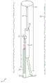
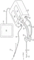
FIG. 1 is a perspective view of a sensor delivery device according to an embodiment of the present invention;
FIG. 2 is a conceptual perspective view of a sensor delivery device for taking physiological measurements according to an embodiment of the invention;
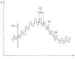
FIG. 3 is a conceptual graph of blood pressure of a patient over time;
FIG. 4(a) is a side view of a sensor delivery device having one or more flow holes disposed along a side portion according to an embodiment of the invention;
FIG. 4(b) is a cross-sectional view of a sensor delivery device having one or more flow holes according to an embodiment of the invention;
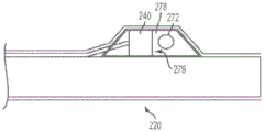
FIG. 5(a) is a cross-sectional side view of a sensor delivery device with a sensor housing according to an embodiment of the invention;
FIG. 5(b) is a cross-sectional side view of a sensor delivery device with a sensor housing according to an embodiment of the invention;
fig. 5(c) and 5(d) are side views of a sensor delivery device with radiopaque marker bands according to certain embodiments of the present invention;
FIG. 5(e) is a cross-sectional side view of a sensor delivery device with a strain-release spacer according to one embodiment of the present invention;
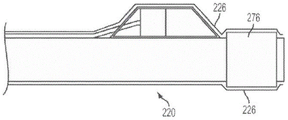
6(a) -6(g) are enlarged side views of a distal transition section of a sensor delivery device according to certain embodiments of the present invention;
7(a) and 7(b) are perspective views of a sensor delivery device having a second sensor disposed on a proximal cannula, in accordance with an embodiment of the present invention;
FIG. 8 is a perspective view of a sensor delivery device having a forked tube according to an embodiment of the invention;
FIG. 9 is a cross-sectional side view of a sensor delivery device having a dual lumen configuration according to one embodiment of the present invention;
10(a) -10(c) are side views of a sensor delivery device having an over-the-wire configuration according to one embodiment of the present invention;
FIG. 11 is a flow chart illustrating a method of using a sensor delivery device according to some embodiments of the present invention;
FIG. 12 is a perspective view of a fluid injection system that may be used to interact with a sensor delivery device according to an embodiment of the present invention;
FIG. 13 is a perspective view of a fluid injection system that may be used to interact with a sensor delivery device according to an embodiment of the present invention;
FIG. 14 is a flow chart of a method of using a sensor delivery device and fluid injection system according to certain embodiments of the present invention;
FIG. 15 is a flow chart of a method of using a sensor delivery device according to some embodiments of the invention;
fig. 16 is a perspective view of an electro-kinetic infusion system adapted for coupling to a physiological sensor delivery device according to certain embodiments of the present invention; and is
FIG. 17 is an idealized view of a user interface screen containing information that may be displayed to an operator, according to some embodiments of the invention.
Detailed Description
The following detailed description should be read with reference to the drawings, in which like reference numerals refer to like elements. The drawings, which are not necessarily to scale, depict selected embodiments of the invention-other possible embodiments may be apparent to those of ordinary skill in the art having the benefit of these teachings. Accordingly, the embodiments shown in the drawings and described below are provided for illustrative purposes and are not intended to limit the scope of the invention as defined in the appended claims.
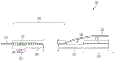
Fig. 1 illustrates an example of a sensor delivery device according to some embodiments of the invention. The sensor delivery device 10 of fig. 1 includes a distal sleeve 20 having a guidewire lumen 22 for slidably receiving a medical guidewire 30. Coupled to the distal sleeve 20 is a sensor 40, the sensor 40 being configured to sense and/or measure a physiological parameter of the patient and generate a signal representative thereof. Thus, the distal sleeve 20, and thus the sensor 40, may be positioned within the patient (e.g., within the patient's anatomy, such as within a vein, artery, or other vessel, or across a heart valve, for example) by sliding the distal sleeve 20 over the medical guidewire 30 to a desired position.
The sensor delivery device 10 of fig. 1 also includes a proximal portion 50 coupled with the distal sleeve 20. The proximal portion 50 includes a communication channel 60 for communicating signals from the sensor 40 to a location outside the patient's body, such as to a processor, display, computer, monitor, or to another medical device. The communication channel 60 may comprise a fiber optic communication channel in certain preferred embodiments, such as where the sensor 40 is a fiber optic pressure sensor. Alternatively, the communication channel 60 may include a conductive medium, such as one or more electrical leads. Of course, many other forms of communication media may be suitable for transmitting the signals generated by the sensors 40 to a location outside of the patient's body. In some embodiments of the present invention, the communication channel 60 may include any of a variety of fluid and/or non-fluid communication media, such as a wireless communication link, or infrared functionality, or acoustic communication (e.g., ultrasound) are possible examples.
The proximal portion 50 is also adapted to assist an operator (e.g., a physician or other medical personnel) in positioning the distal sleeve 20 and sensor 40 within an anatomical (e.g., vascular) structure of a patient. This is typically accomplished by the operator first inserting a "standard" medical guidewire 30 into the patient's blood vessel and advancing it through the region of interest. The sensor delivery device 10 is then deployed by "threading" the distal sleeve 20 over the guidewire 30 such that the lumen 22 slides over the guidewire 30, and advancing the distal sleeve 20 (and associated sensor 40) by moving (e.g., pushing and/or pulling) the proximal portion 50 until the sensor 40 is in the desired position.
The device 10 and guidewire 30 are typically maneuvered within a guide catheter 32 that has been placed within an anatomical (e.g., vascular) structure of interest. In certain preferred embodiments of the present invention, the guidewire lumen 22 may be sized for sliding over a "standard" sized medical guidewire. For example, many manufacturers make medical guidewires that range in size from less than about 0.014 inch outer diameter to greater than about 0.038 inch outer diameter, typically with a limited number of common sizes in this range. "Standard" sized medical sizes, for example, may have outer diameters of 0.010, 0.014, 0.018, 0.021, 0.025, 0.028, 0.032, 0.035, and 0.038 inches. Thus, in certain preferred embodiments of the present invention, the guidewire lumen 22 may be sized to slide over a particular standard size medical guidewire. Devices according to embodiments of the present invention are thus available in a size range corresponding to standard medical guidewire sizes.
One potential advantage of the sensor delivery device 10 according to various embodiments of the present invention is to allow physicians to use their selected guidewire. The sensor delivery device 10 may be sized for use with any guidewire. The physician may select a particular guidewire for certain procedures, for example, based on its unique deflection and torque characteristics. The delivery device 10 according to various embodiments of the present invention enables a physician to use any of the guidewires that are deemed most appropriate for a particular application.
Another potential advantage of the sensor delivery device 10 is that the guidewire does not need to be repositioned in order to take sensor readings. Once the guidewire has been positioned across, for example, a stenotic lesion, the sensor delivery device 10 may be positioned (e.g., advanced and/or retracted) over the guidewire and the sensor 40 may thus be advanced and retracted across the lesion to take, for example, pressure readings without the need to move the guidewire. The physician may also save time by not having to reposition the guidewire across one or more lesion regions to perform such measurements.
In the example shown in fig. 1, the device 10 is deployed using a guide catheter 32 that has been placed within a vascular structure of interest (in this example, a blood vessel 34, which may be, for example, a coronary artery of a patient). In some embodiments of the invention, the size or "footprint" (e.g., width and/or cross-sectional area) of the device 10 may allow it to fit within some standard sized guide catheter. For example, in certain diagnostic applications, it may be desirable to deploy the device 10 within a guide catheter of a certain size (e.g., less than about 4 or 5French (French catheter standard) (FR)).
In some embodiments, the distal sleeve 20 of the device may be substantially concentric with the guidewire 30. The coupling of the proximal portion 50 to the distal sleeve 20 allows the guidewire 30 to be separated from the rest of the device 10 (e.g., in a configuration sometimes referred to as a "single track" catheter); this will typically occur within the guide catheter 32. Both the guidewire 30 and the device 10 will exit the patient as separate devices at the proximal end of the guide catheter 32. Separating the device 10 and guidewire 30 allows the physician to independently control the device 10 and guidewire 30, if necessary. This may also allow the physician to use a shorter guidewire for catheter replacement. For example, a monorail-type configuration may allow for the use of a guidewire that is approximately 170 to 200cm long, while an "over the guidewire" configuration may require the use of a much longer guidewire (e.g., up to 300cm or more). Separating the device 10 and the guidewire 30 (other than at the distal sleeve 20) may also result in less friction (e.g., within the guide catheter 32) than if the device 10 and the guidewire 30 had to be moved together as a unit. In some embodiments, hydrophilic coatings may be applied to various portions of the device in order to further reduce the amount of friction encountered, for example, when advancing or retracting the device 10.
One diagnostic application to which various embodiments of the present invention may be applied is the measurement of Fractional Flow Reserve (FFR). As described above, this FFR measurement quantifies the extent to which a stenotic lesion, for example, obstructs flow through a blood vessel. To calculate the FFR for a given stenosis, two blood pressure measurements are required, one pressure reading taken on the distal (downstream) side of the stenosis and the other pressure reading taken on the proximal (upstream) side of the stenosis. FFR is thus a unitless ratio of this distal pressure to the proximal pressure. The pressure gradient across the stenotic lesion is an indication of the severity of the stenosis. The more restrictive the stenosis, the greater the pressure drop and the smaller the FFR.
To increase the clarity and context of the present disclosure, several embodiments of the present invention will now be described in the context of making FFR measurements. However, it should be appreciated that there are other applications in which the devices and/or methods described herein may be used to facilitate measurement of physiological parameters.
Fig. 2 is a perspective view of a sensor delivery device for measuring a physiological parameter of a patient according to an embodiment of the present invention. The embodiment shown in fig. 2 may be deployed, for example, to make FFR measurements in a patient's vessel. Fig. 2 shows the sensor delivery device 210 deployed in a vessel (e.g., coronary artery 234) of a patient across a stenosis (e.g., stenotic lesion 236). To make FFR measurements, for example, a first sensor 240 may be positioned at a location 231 downstream of a location of interest (e.g., stenotic lesion 236) to measure a distal (downstream) blood pressure Pd. The first sensor 240 may then be positioned at a location 233 upstream of the location of interest (e.g., the stenotic lesion 236) to measure the proximal (upstream) blood pressure Pp. FFR is simply calculated as the ratio of the distal pressure to the proximal pressure, or FFR ═ Pd/Pp). The terms "downstream" and "upstream" are used with respect to the normal direction of blood flow as indicated by "D" in FIG. 2.
In fig. 2, a first sensor 240 is coupled to the distal sleeve 220. In the embodiment shown in fig. 2, the first sensor 240 is coupled to an outer surface of the distal sleeve 220. The first sensor 240 is adapted to measure a physiological parameter of the patient, such as a blood parameter (e.g., blood pressure, temperature, pH, blood oxygen saturation level, etc.), and generate a signal representative of the physiological parameter. In certain preferred embodiments of the present invention, the first sensor 240 is a fiber optic pressure sensor adapted to measure blood pressure. An example of the fiber optic pressure sensor is a Fabry-Perot type fiber optic pressure sensor, which is a commercially available sensor. Examples of fabry-perot type fiber optic pressure sensors are "OPP-M" MEMS-based fiber optic pressure sensors (400 micron size) manufactured by Quebec, Canada, european parmesan (essens), and "FOP-MIV" sensors (515 micron size) manufactured by femtology corporation (Fiso Technologies, Inc.). In certain alternative embodiments, the first sensor 240 may be a piezoresistive pressure sensor (e.g., a MEMS piezoresistive pressure sensor), and in other embodiments, the first sensor 240 may be a capacitive pressure sensor (e.g., a MEMS capacitive pressure sensor). The pressure sensing range, for example, from-50 mm Hg to about +300mmHg (relative to atmospheric pressure) is desirable for most physiological measurements using sensor 240.
In embodiments of the present invention using a fabry-perot type fiber optic pressure sensor as sensor 240, such a sensor operates by having a reflective diaphragm that varies a cavity length measurement in accordance with the pressure against the diaphragm. Coherent light from a light source travels down the fiber and through a small cavity at the sensor end. The reflective membrane reflects a portion of the optical signal back into the optical fiber. The reflected light travels through the optical fiber back to the detector at the source end of the optical fiber. The two light waves, the source light, and the reflected light travel in opposite directions and interfere with each other. The amount of interference will vary depending on the cavity length. The cavity length will vary as the diaphragm deflects under pressure. The amount of interference is recorded in a fringe pattern detector.
Fig. 2 shows a proximal portion 250 coupled to the distal sleeve 220. The proximal portion 250 includes a communication channel 260 for communicating physiological signals from the sensor 240 to a location outside the patient's body (e.g., to a processor, display, computer, monitor, or to another medical device). The proximal portion 250 may preferably be formed of a material having sufficient rigidity to assist an operator (e.g., a physician or other medical personnel) in positioning the distal sleeve 220 and sensor 240 within the anatomy (e.g., blood vessel) of a patient.
One material suitable for use in proximal portion 250 may be, for example, a stainless steel hypotube. Depending on the application, the proximal portion 250 (also sometimes referred to as a "delivery tube") should typically be more rigid and rigid than the distal sleeve 220 in order to provide a reasonably controlled amount to push, pull and otherwise manipulate the device to a physiological location of interest within the patient. For example, in interventional cardiac surgery, at least a portion of the proximal portion 250 will be maneuvered within a guide catheter located within a coronary artery. In such applications the proximal portion 250 should therefore be sufficiently flexible to accommodate the aortic arch, while being sufficiently rigid to push and pull the device. Accordingly, materials suitable for use in the proximal portion 250 may also include materials (other than the stainless steel hypotube described above) such as, for example, nitinol, nylon, and plastic, or composites of multiple materials.
The communication channel 260 may be disposed along an outer surface of the proximal portion 250 or may be formed within the proximal portion 250, as shown in fig. 2. For example, in some embodiments, the communication channel 260 can include a communication lumen extending longitudinally through the proximal portion 250. In some embodiments, the communication channel 260 may comprise a fiber optic communication channel, such as in the case where the sensor 240 is a fiber optic pressure sensor. Alternatively, the communication channel 260 may include a conductive medium such as an electrical wire, or other suitable communication medium for transmitting the signal generated by the sensor 240. In a preferred embodiment of the present invention, the communication channel 260 includes a non-fluid communication medium. In the embodiment shown in fig. 2, a communication channel 260 (e.g., a fiber optic cable) extends distally beyond the proximal portion 250 and couples to the sensor 240. In such embodiments, the communication channel 260 is at least partially housed within a communication lumen (e.g., stainless steel hypotube) of the proximal portion 250.
FIG. 2 also illustrates an alternative embodiment of the present invention, wherein a second sensor 242 may be coupled to the device 210. For example, the second sensor 242 may be coupled to the proximal portion 250 such that the first and second sensors 240, 242 are sufficiently spaced apart (e.g., separated by a fixed distance) to span a stenotic lesion. This embodiment may provide the ability to measure FFR without having to reposition the device 210, as the first sensor 240 may be placed distal to the stenotic lesion 236 to measure PdAnd a second sensor 242 may be placed proximal to the stenotic lesion 236 to measure Pp. The second sensor 242 may have a communication channel 262 (which may be housed within the proximal portion 250) or may be disposed along an outer surface of the proximal portion 250, for example, as shown in fig. 2. Furthermore, P is measured substantially simultaneouslydAnd PpMay improve accuracy and/or reduce the effects of certain types of errors shown and described below with reference to fig. 3。
It should be noted that certain embodiments may have more than 2 sensors, and the spacing between adjacent sensors may be varied in such embodiments to provide variable spacing capability. In certain alternative embodiments of the present invention, one or more sensors may be disposed on the proximal portion 250, for example, without a sensor disposed on the distal sleeve 220. In some alternative embodiments, it may be desirable to have multiple sensors (two, or three, or four, or more sensors) arranged along the proximal portion 250 spaced apart by a known, fixed distance. This may, for example, provide for obtaining P by selecting (from the plurality of sensors) an appropriate pair of sensors to be placed across the lesion, independent of lesion lengthdAnd PpSignals to measure P substantially simultaneouslydAnd PpThe ability of the cell to perform. In addition, the sensors may have some form of radiopaque marker (e.g., a marker band) incorporated thereon, which may incorporate a physiological parameter (e.g., P)dAnd Pp) Provides a visual estimate of the size of the lesion.
In some embodiments, it may be desirable to measure the distal pressure P with a sensor external to the guide catheter (protruding distally of the distal end of the guide catheter)dAnd a sensor 240 or 242 within the guide catheter measures the proximal pressure Pp. In this way, it can be ensured that the proximal measurement is made proximal to the lesion, rather than erroneously within the lesion. If the proximal pressure PpIf the measurement is taken within the location of interest (e.g., lesion), the measurement may be inaccurate, resulting in a wrong FFR and possibly inaccurate treatment recommendation. PpEmbodiments that are performed within a guide catheter thus minimize or prevent this type of error, thereby improving the accuracy of FFR calculation and subsequent treatment decisions.
In embodiments with only a single sensor 240, this may be done by first measuring P within the guide catheterpAnd then extending the distal cannula to position the sensor 240 to the location of interestDownstream to measure PdAnd then the operation is completed. Alternatively, the distal sleeve may be extended to position the sensor 240 downstream of the location of interest to measure PdAnd may then be retracted into the guide catheter across the location of interest to measure Pp. In embodiments with two or more sensors, the first sensor 240 may be positioned downstream of the location of interest to measure PdAnd a second sensor 242 or other more proximal sensors is positioned proximal to the location of interest and within the guide catheter to measure Pp. The apparatus 210 may be configured such that the length of the guide catheter and the distance between the first sensor 240 and the second sensor 242 or other more proximal sensors is sufficient to allow the distal sensor to be positioned distal to a location of interest without adjusting the position while the proximal sensor is still proximal and within the guide catheter, wherein the location of interest is at a varying distance from the distal end of the guide catheter. For example, the location of interest may be between about 10 and about 30 centimeters distal of the distal end of the guide catheter. The apparatus 210 may be configured such that the spacing between the first sensor 240 and the second sensor 242 or other sensors, and the second sensor 242 or other sensors measure P thereinpIs of sufficient length to allow the first sensor 240 to be positioned distal to the location of interest in order to measure PdWherein the proximal sensor 242 or other sensor is located within the guide catheter and at varying distances from the location of interest.
As described above, sensors 240 and 242 and/or other additional sensors, etc. may include radiopaque markers. In some embodiments, the guide catheter may also include a radiopaque marker, for example within a distal portion that includes the distal end of the guide catheter. In this way, the position of the sensors 240, 242 within the guide catheter may be measured P while performing a procedurepIs seen by the clinician.
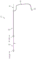
Fig. 3 graphically illustrates several other possible sources of error in measuring blood pressure, such as they may affect the calculation of FFR, among others. FIG. 3 is directed toA conceptual plot p (t) of the blood pressure 340 of a given patient over time. One potential error in calculating FFR is blood pressure fluctuations due to the systolic and diastolic phases of the cardiac cycle 342. Unless PdAnd PpAre measured at substantially the same time of the cardiac cycle 342, otherwise a certain amount of error may be introduced. Similarly, the effect of the breathing cycle (e.g., inhalation and exhalation) on blood pressure may also be a source of error causing slower changes, as shown at 344 of fig. 3. A third source of error may be caused by a change in the patient's posture, which may raise or lower the overall pressure curve as indicated at 346 in fig. 3. Of the invention with substantially simultaneous measurement of PdAnd PpVarious embodiments of the capability (e.g., the dual sensor embodiment shown in fig. 2) may be able to minimize or eliminate the impact of such "timing errors" on the FFR calculation. Another approach to addressing the effects of such "timing errors" will be discussed below in the context of using a contrast media injection system in conjunction with a sensor delivery device, according to some embodiments of the present invention.
In some embodiments, one or more of the sensors may comprise one or more materials that together have a low thermal coefficient, e.g., a substantially zero thermal coefficient. In some embodiments, the sensor includes one or more materials that together have a thermal coefficient of pressure between approximately-0.1 and 0.1mmHg/° C. The portions of the sensor that contribute to the pressure readings may include materials with low thermal coefficients. This may include, for example, any component that can change the width of the sensor cavity, which may change with pressure but may also change with temperature. This may be achieved by forming the sensor from a set of materials having opposite thermal coefficients such that the net thermal coefficient of the cavity is close to zero, for example between approximately-0.1 and 0.1mmHg/° c. Using one or more sensors with low thermal coefficients may avoid errors that may result from the sensors losing calibration with atmospheric pressure in a warmer environment moving into the patient's body, which in turn may result in erroneous calculation of FFR. In some embodiments, one or more of the sensors may comprise a material having a thermal coefficient sufficiently low such that the sensor is calibrated to atmospheric pressure after the sensor temperature changes from approximately room temperature (e.g., approximately 70-72 degrees fahrenheit) to approximately normal body temperature (e.g., approximately 96-99 degrees fahrenheit). The sensor or sensors comprising materials with low thermal coefficients are still calibrated to atmospheric pressure after introduction into the bloodstream, while any sensor comprising materials with higher thermal coefficients may lose calibration due to the temperature of the bloodstream. Because at least one of the sensors includes a material with a low thermal coefficient and is calibrated to atmospheric pressure despite being introduced into the body, any other device sensor that does not include a material with a low thermal coefficient can be corrected by balancing it with the sensor or sensors that include a material with a low thermal coefficient.
Prior to use in operation, the sensor or sensors comprising materials with low thermal coefficients may be calibrated to atmospheric pressure outside the patient's body. These sensors may then be introduced into the patient's bloodstream as part of the procedure to insert the device. These sensors may be balanced if one or more of the sensors does not include a material having a low thermal coefficient, wherein any sensor that does not include a material having a low thermal coefficient is calibrated to match a sensor having a low thermal coefficient. This may be done after positioning the sensors at a location proximal to the location of interest, before taking a pressure measurement. This balancing step may not be required if all sensors comprise materials with low thermal coefficients.
The benefits of using a sensor with a material having a low thermal coefficient can be understood by considering the pressure changes due to temperature dependent pressure sensing. This can be explained by the following equation:

wherein Due to the temperature-induced pressure excursion of the distal sensor,
 is the pressure excursion of the proximal sensor due to temperature, and Δ is the compensation value introduced when the pressures are balanced. If the sensors return to zero at room temperature in vitro and equilibrate when reading the same pressure, then
 And is
 The FFR error due to the temperature dependence of the sensor is therefore:

the use of a sensor with a low thermal coefficient of pressure can thus be used in a number of different embodiments in order to minimize the influence of temperature variations on the pressure measurement. The FFR value that is desired to have the highest accuracy is at the treatment decision threshold, typically 0.8 FFR. Further, the FFR is a measurement that can be obtained at a pressure of about 100mmHG, which is typical of aortic pressure. In some embodiments, the sensor may be designed to have a pressure thermal coefficient that is less than 0.01 FFR error due to temperature effects at 0.8 FFR and 100mmHg pressure.
Referring again to fig. 2, the distal sleeve 220 may be generally tubular (as shown) or may have any shape that allows the distal sleeve 220 to slide over the medical guidewire 230 in the anatomy of interest (e.g., a blood vessel). For example, in the context of measuring FFR in a coronary artery, it may be desirable for the cross-section of the distal sleeve 220 to be generally cylindrical in order to minimize the overall cross-sectional area of the device. In some embodiments, the distal sleeve 220 may preferably be formed of a flexible material to facilitate positioning and placement of the distal sleeve 220 (and sensor 240) over a guidewire 230 traversing a narrow vascular structure (e.g., coronary arteries). In certain preferred embodiments, the distal sleeve 220 comprises a flexible polyimide tube sized for placement in an anatomical (e.g., vascular) structure of interest, such as a coronary artery or a peripheral artery. In some embodiments, the distal sleeve 220 may comprise a flexible microcoil tube. In some embodiments, flexibility may be achieved and/or enhanced by applying a series of cuts along the surface of the tube. For example, a plurality of cuts or notches may be applied along the length of the outer surface of the distal sleeve 220 (e.g., by laser cutting techniques known to those of ordinary skill in the art). Such cuts or notches may be generally circumferentially oriented and may extend at least partially around the circumference of the distal sleeve. According to the following embodiments, successive cuts may be angularly offset from each other to provide flexibility in all directions.
The length of distal sleeve 220 may be varied. In embodiments to be used in coronary arteries, for example, the distal cannula 220 may be up to about 15 inches long, and in some preferred embodiments may be 11 inches long (e.g., to facilitate use deep within certain coronary arteries). In some embodiments, distal sleeve 220 may also include a thin covering to provide additional structural support to the device and/or to improve the handling characteristics of the device. Such a covering may comprise, for example, a Polyester (PET) shrink tube that substantially covers the distal sleeve.
The distal cannula 220 has a guidewire lumen 222 sized for slidably receiving a guidewire 230 having an outer diameter between about 0.010 inches and 0.050 inches. For FFR measurements in the coronary artery 234, for example, the outer diameter of the guidewire 230 may preferably be 0.014 inches and the inner diameter of the guidewire lumen 222 therefore needs to be slightly larger than this in order to facilitate slidable movement of the distal sleeve 220 over the guidewire 230.
Fig. 4(a) illustrates one embodiment of the present invention in which one or more flow apertures 224 are disposed along the distal sleeve 220 (e.g., along the length of the distal sleeve 220). If the operator pulls back (e.g., retracts) the guidewire 230, the flow aperture 224 may allow blood to flow into the guidewire lumen 222, as shown in fig. 4 (a). Such embodiments may improve accuracy in measuring pressure drop across a narrow region, as the pressure drop caused by the device itself will be reduced by reducing the effective cross-sectional area of the device.
Fig. 4(b) is a cross-sectional view of one embodiment of the present invention, illustrating the potential reduction in cross-sectional area that may be obtained by using flow holes 224 in the side portion of the distal sleeve 220. For example, by allowing blood to flow through the flow aperture 224 into the guidewire lumen 222, the effective cross-sectional area of the device 210 is reduced by the area of the guidewire lumen 222, and any errors in the blood pressure measurement caused by the flow obstruction of the device 210 itself will be correspondingly reduced.
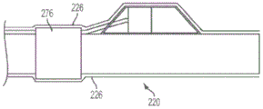
Fig. 5(a) is a cross-sectional side view of a portion of an apparatus 210 according to some embodiments of the invention. Fig. 5(a) illustrates distal sleeve 220 and first sensor 240 of an embodiment in which sensor 240 is provided with a degree of protection by being at least partially covered by a sensor housing 270 disposed on distal sleeve 220. The sensor housing 270 may be generally tubular or may be semi-circular, or may be any other shape that provides suitable protection to the sensor 240. The sensor housing 270 may be constructed from, for example, polyimide tubing capable of forming a relatively thin wall thickness.
The sensor housing 270 may be constructed in a number of different ways, as described with reference to fig. 5(a) to 5 (e). For example, fiber optic sensors may be somewhat fragile and are typically equipped with some form of mechanical protection against stress and/or strain relief. The sensing head of the sensor 240 is typically attached to the communication channel 260 (e.g., fiber optic cable) with an adhesive. The sensing head may be susceptible to being pulled away from (e.g., disconnected from) the fiber without requiring too much force, as the bonding area is typically very small. Fig. 5(a) to 5(e) illustrate several techniques for minimizing or eliminating the effect of such stresses on the sensor 240 using a protective sensor housing 270 surrounding the sensor 240.
One material that may be used to construct sensor housing 270 is a heavy metal that is visible to X-rays, such as platinum. Sensor housing 270, formed of platinum, may provide an x-ray marker band to aid in the placement and positioning of sensor 240. The platinum sensor housing 270 may be formed to be generally thin, for example, about 0.001 inches thick. Such a thin-walled platinum sensor housing 270 may provide adequate protection to the sensor 240 from stresses that might otherwise cause the sensor to become detached from the communication channel 260.
In some embodiments, the sensor housing 270 may be shaped to assist in the movement and placement of the device within the anatomy (e.g., blood vessel) of the patient. For example, as shown in fig. 5(a), forward and rearward portions 274 of sensor housing 270 may be formed at an angle (e.g., cut at an angle) to present a smoother tapered structure that is easier to advance through anatomical (e.g., vascular) structures and passageways within a patient (e.g., it allows device 210 to slide through a vascular passageway, such as an artery wall, without jamming or snagging).
In some embodiments, sensor housing 270 may be formed as part of the process of forming distal sleeve 220. For example, a generally cylindrical mandrel may be used to form distal sleeve 220, which is made of a thermoset polymer (e.g., polyimide) using an immersion plating process. A slight modification of this manufacturing method may use a "shell forming element" located alongside the mandrel at the distal end of the mandrel. A single immersion plating process may thus form sensor housing 270 as an integral part of distal sleeve 220.
In some embodiments, an optional cover 226 may be applied over the sensor housing 270 and the distal sleeve 220. Such coverings 226 may facilitate movement and positioning of the device 210 within anatomical (e.g., vascular) structures of a patient. The cover 226 may also provide additional structural stability to the sensor 240, housing 270, and distal sleeve 220 arrangement. An example of a class of materials that may be suitable for forming the cover 226 is thermoplastics. Such materials may sometimes be referred to as thin-walled heat shrink tubing and include materials such as polyolefins, fluoropolymers (PTFE), polyvinyl chloride (PVC), and polyesters, particularly polyethylene terephthalate (PET). For simplicity, the term "PET tube" is used herein with respect to embodiments incorporating such thin covering materials. In embodiments with or without the housing 270, use of a PET tube, for example, may be employed.
PET tubing is a heat shrinkable tube made from polyester that exhibits excellent tensile strength characteristics while having a wall thickness as small as 0.0002 inches. A PET tube may be used to encapsulate the distal sleeve 220 in some embodiments of the present invention. This may include, for example, wrapping the sensor housing 270 and/or a portion of the communication channel 260 (e.g., the fiber optic cable) to a length that wraps around the communication channel 260 extending from the proximal portion 250. In some embodiments, the PET tube may also extend over a portion of the proximal portion 250, for example over where it is coupled to the distal sleeve 220. In some embodiments, a PET tube may be used to hold the fiber optic communication channel 260 in place around the distal sleeve 220. After the PET tube has been heat shrunk, one or more openings may be cut into the PET tube, for example, to allow the guidewire 230 to exit.
Fig. 5(a) shows a fluid opening 272 formed in one of the portions 274 of the sensor housing 270 (e.g., the forward portion in this example). Fluid opening 272 allows fluid (e.g., blood) to flow into sensor housing 270 and into fluid contact with sensor 240. In embodiments incorporating a cover 226 (e.g., a PET tube), fluid openings 272 may be formed in the cover 226.
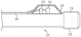
Fig. 5(b) illustrates an embodiment of the present invention in which fluid openings 272 are formed in a side portion of housing 270. This arrangement may result in a reduced likelihood of "jamming" within the sensor housing 270 and/or a reduced likelihood of catching or snagging on any obstacles or corners encountered when positioning the device 210. For example, platelets or calcium ions from the arterial wall may enter the housing 270 as the device moves through the artery; having fluid openings 272 in the side portions of the housing 270 may reduce this effect. In some embodiments, allowing the PET tube cover 226 to remain intact at the distal end of the housing 270 may prevent foreign objects from entering the housing 270 and possibly damaging the sensor 240, or affecting the accuracy of the pressure measurement. After the PET tube cover 226 has been heat shrunk on the device 210, a plurality of holes (if needed) may be pierced through the cover 226 to form fluid openings 272 to allow fluid to access (e.g., blood flow into) the interior of the sensor housing 270.
In some embodiments of the present invention, the interior portion of sensor housing 270 may be filled with a gel 278, such as a silicone dielectric gel. Silicone dielectric gels are commonly used with solid state sensors to protect the sensor from exposure to, for example, fluid media. If the sensor housing 270 is filled with gel 278 in front of the sensor membrane 279, it will be less likely that foreign matter will penetrate into the interior of the housing 270. The gel 278 may also provide increased structural stability to the sensor 240, and/or may enhance the pressure sensing characteristics of the sensor 240. Gel 278 may be used in any of the embodiments of sensor housing 270 shown in fig. 5(a) -5 (d) and equivalents thereof.
In fig. 5(c) and 5(d), various embodiments of the present invention are shown including selectable marker bands. If sensor housing 270 is formed from, for example, polyimide tubing, device 210 may not be visible in x-rays. An optional marker band 276 may be placed near one end of the distal sleeve 220. The marker band 276 may provide a visual indication of the location of the sensor 240 when viewed under X-rays. As shown in fig. 5(c), a marker band 276 on one end of the distal sleeve 220 may provide some structural reinforcement to that end of the distal sleeve 220. In an alternative embodiment shown in fig. 5(d), marker band 276 on distal sleeve 220 proximal to sensor housing 270 may reduce the likelihood of marker band 276 being forcibly removed from device 210. In some embodiments, it may be desirable to include a plurality of such marker bands spaced at known distances (e.g., every 10mm along the distal cannula 220) so that they can be used to provide a visual estimate of length or distance (e.g., to measure lesion length).
Fig. 5(e) shows such an embodiment: spacers 278 are used to provide strain relief at the connection between sensor 240 and communication channel 260. This strain relief member may be made of any suitable material such as, for example, Polyetheretherketone (PEEK). In some embodiments, spacers 278 may also be formed to function as marker bands 276 generally as described above. Spacer 278 may be implemented in embodiments with sensor housing 270, or embodiments without a sensor housing.
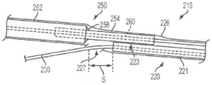
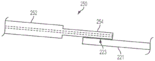
Fig. 6(a) shows an enlarged side view of a portion of an apparatus 210 according to one embodiment of the present invention. The delivery tube (proximal portion 250) and distal sleeve 220 are preferably coupled together using a flexible bonding method (medical adhesive) to maintain the flexibility of the device 210. In some preferred embodiments, for example, the proximal portion 250 will bond to the outer surface 221 of the distal sleeve 220 with the bonding region 223. The bonding region 223 is preferably disposed on the distal cannula 220 sufficiently proximal to the sensor 240 such that the bonding region 223 is not within the vascular structure or passageway of interest (e.g., not within an arterial vessel near the stenosis), but is still within the guide catheter 232. The bonding or adhesive area 223 preferably maintains some flexibility to accommodate bends, such as in the aortic arch. As previously mentioned, it may be desirable to minimize the width of the device 210 so that it may pass through, for example, a relatively small guide catheter 232. This goal may be achieved at least in part by making the bond region 223 as narrow as possible. In some embodiments, it is desirable to use the sensor delivery device 210 within a diagnostic guide catheter 232 of generally 4 Fr.
In some embodiments, a significant reduction in the width of the device 210 may be obtained using a distal transition 254 to couple the proximal portion 250 to the distal sleeve 220. In certain preferred embodiments of the present invention, device 210 will be able to pass through a 4Fr guide catheter 232. The embodiment of fig. 6(a) has a proximal portion 250 that includes a main section 252 and a distal transition segment 254. A distal transition segment 254 extends distally from the main segment 252 and is coupled to the outer surface 221 of the distal sleeve 220 at the bond region 223. As shown in fig. 6(a), the use of a distal transition 254 to couple the proximal portion 250 to the distal sleeve 220 may result in a reduced width of the device 210 as compared to the device 210 without the distal transition 254. This may be accomplished, for example, in embodiments where the distal transition section 254 has a smaller cross-sectional area than the main section 252. (of course, the distal transition 254 is optional and may not be required in all embodiments of the invention; such embodiments, as shown in FIGS. 1, 2, and 4, do not include a distal transition; such embodiments may, for example, result in a simpler manufacturing process.)
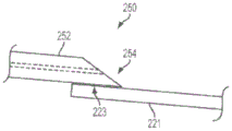
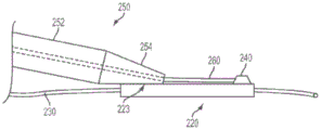
In the embodiment shown in fig. 6(a), the distal transition 254 may be substantially coaxial and/or concentric with the main section 252 and smaller in diameter than the main section 252. In some embodiments, the distal transition segment 254 may be formed by inserting a hypotube into one end of the proximal portion 250, the hypotube having a diameter that is somewhat smaller than the diameter of the proximal portion 250. The hypotube distal transition 254 and proximal portion may then be welded together as shown at 256. The distal sleeve 220 (which may comprise a thin-walled tube formed from a material such as polyimide) may then be bonded to the smaller diameter distal transition section 254. Alternatively, the distal sleeve 220 may be formed from a microcoil of flat wire wound with the PET tubing heat shrunk onto the microcoil. Embodiments using stainless steel microcoils for distal sleeve 220 may provide a lower coefficient of friction (e.g., compared to polyimide) to reduce sliding friction. However, such a micro-coil embodiment would likely benefit from the use of a PET tubing cover 226 to provide reinforcement and/or to provide a smooth surface. PET tubing may be used to form the cover 226 as shown in fig. 6(a) and generally as described above. Once the PET tube cover 226 has been heat shrunk, for example, in the region of the distal transition 254, the cover 226 may have one or more openings 227 formed in the PET tubing, for example, for creating an exit 227 for the guidewire 230, as shown. It is noted that while shown only in fig. 6(a), the embodiments shown in fig. 6(a), 6(b), and 6(c) may all include an optional cover 226 (e.g., a PET tube) according to some embodiments of the present invention.
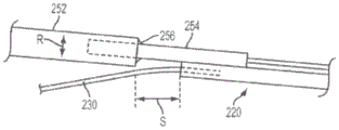
Figure 6(b) illustrates one embodiment of the present invention in which the longitudinal axis of the distal transition section 254 is radially offset from the longitudinal axis of the main section 252 by a distance "R" to provide a further potential reduction in, for example, the width of the device 210, thereby minimizing the footprint of the device 210 and allowing the use of a relatively small guide catheter. Fig. 6(c) shows an embodiment in which the radial offset distance "R" is in the opposite direction to the offset distance "R" shown in fig. 6 (b). This arrangement may provide more clearance for the guidewire 230 as it exits the distal sleeve 220 in the region near the distal transition segment 254.
Fig. 6(a) and 6(b) also illustrate techniques that may be used to form the distal transition segment 254. For example, the distal transition section 254 may be formed by welding or brazing a tubular member to the main section 252 (as shown at 256). As shown, the tubular member 254 may extend into one end of the main section 252 and may include a communication channel 260 (e.g., an extension of the communication channel 260 within the main section 252). Alternatively, the distal transition segment 254 may be formed by "swaging" the distal end of the main section 252 (as shown at 256). The term "swaging" as used herein encompasses a variety of manufacturing methods that reduce the diameter of a workpiece, such as by forcing the workpiece (or a portion thereof) through a confining die, or by hammering a circular workpiece into a smaller diameter workpiece (e.g., rotary or radial forging).
Other methods for forming the distal transition segment 254 may include grinding (e.g., to reduce the outer diameter of the single piece from the outer diameter of the main segment 252 to the outer diameter of the distal transition segment 254), or use of adhesives or glues (e.g., epoxy, ultraviolet adhesive, cyanoacrylate, etc.), or thermoforming, and/or other techniques known to those of ordinary skill in the art. Fig. 6(d) and 6(e) illustrate exemplary embodiments that may be formed by, for example, grinding or other comparable techniques. Additionally, the distal transition segment 254 need not extend into the main section 252 and may instead be held in abutting relation with the main section 252 using some of the techniques described above.
Fig. 6(a) and 6(b) coincidentally illustrate the following embodiments of the present invention: wherein the distal transition section 254 is used to "back" the main section 252 from the distal sleeve 220 by a distance "S" as shown. This may be advantageous, for example, in creating additional "clearance" for the guidewire 230 as it exits the distal sleeve 220. However, setback is not a requirement and embodiments of the invention may be implemented with zero setback, as shown in fig. 6(c) (e.g., S-0).
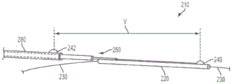
FIG. 7(a) shows one possible embodiment of the present invention: wherein the second sensor 242 is coupled to the proximal sleeve 280, thereby allowing the first and second sensors 240, 242 to be spaced apart by a variable distance, shown as "V". In such embodiments, the proximal sleeve 280 is adapted to be moved longitudinally (e.g., advanced and/or retracted) by an operator by sliding over the proximal portion 250 to achieve a desired spacing, shown as a "V".
Fig. 7(b) shows the following alternative embodiment: wherein the multi-lumen shaft 290 (e.g., formed of a polymer) includes a guidewire lumen 292 for an extendable/retractable first sensor 240 disposed on a distal end of an extendable/retractable sensor shaft 296, a sensor lumen 294, and a second sensor 242 coupled to an outer portion of the multi-lumen shaft 290, the sensor shaft 296 being slidably received within the sensor lumen 294. The first and second sensors 240, 242 may be spaced apart by a variable distance (e.g., a stenotic lesion across other anatomical locations of interest within the patient) by slidably moving the sensor shaft 296 relative to the multi-lumen shaft 290 (e.g., by moving the sensor shaft 296 within the sensor lumen 294).
Fig. 8 shows a device 210 according to an embodiment of the invention in which the proximal end of the proximal portion 250 is interconnected with a fiber-optic prongs 290 (e.g., in embodiments of the invention where a fiber-optic sensor is used). The fiber prongs 290 provide an extension of the fiber optic communication channel 260 (from the sensor 240 through the proximal portion 250) to an optional connector 294 (e.g., an "SC" fiber optic connector). The prongs 290 may be provided with an SC connector 294, for example, to allow the device 210 to transmit signals from the sensor 240, for example, to other devices, monitors, fluid infusion devices, displays, and control units, etc. According to some embodiments, the prongs 290 may comprise Kevlar (Kevlar) fiber reinforced tubing (e.g., for strength). In some alternative embodiments, the forked tube 290 may be formed from coaxial tubing.
The length of the forked tube 290 may be selected to extend from the device 210 in the sterile field (e.g., where the patient is located) to a location outside the patient (e.g., a medical fluid injector), or to a separate display device, or to some other processing or computing apparatus 296 located at a distance from the patient. SC connector 294 is adapted for interconnection with a suitably configured injector (or other signal processing unit). If signal processing is done within the injector, the injector display may be utilized to display the pressure waveform and/or calculate and display the FFR value.
An alternative embodiment of the present invention would be to construct the distal portion 300 of the sensor delivery device 210 by using a dual lumen configuration. An example of such an embodiment is shown in fig. 9. One lumen of the distal portion 300 will receive the fiber optic communication channel 260 from the sensor 240 (and in some embodiments from the sensor housing 270). Another lumen (e.g., guidewire lumen 222) would be adapted to slide over guidewire 230 as shown. In such embodiments, the guidewire 230 will exit the dual-lumen distal portion 300 through the opening 320 in the device 210 at a distance (e.g., approximately 10-12 inches) back (e.g., proximally) from the sensor 240. In some embodiments, a reinforcement wire 310 may be placed in the remaining proximal portion of the lumen 222 (e.g., the portion of the guidewire lumen 222 in the proximal portion 250 of the device 210). The stiffness of the stiffening wire 310 may be varied, for example, to assist a physician in deploying and positioning the device 210 through a catheter into a particular anatomical (e.g., vascular) structure of interest. According to some embodiments, the reinforcement wire 310 may be part of the dual lumen device 210 or may be an optional removable object selected by the physician to achieve a desired amount of stiffness.
Another alternative embodiment of the present invention would be an over-the-wire (OTW) device, generally as shown in fig. 10. Fig. 10 illustrates an embodiment of the invention in which both the distal sleeve 220 and the proximal portion 250 of the sensor delivery device 210 are adapted to slide over the guidewire 230. In such embodiments, the guidewire 230 does not exit the device 210 or separate therefrom at some point along the length of the device 210. Instead, the entire length of the proximal portion 250 of the device 210 slides over the guidewire 230 within the guide catheter (not shown). This design of the device may cooperate with two tubes of different sizes, for example to form the distal sleeve 220 and the proximal portion 250. For example, a smaller diameter, thin walled tube may form the distal sleeve 220, where the sensor 240 rests (optionally within the sensor housing 270). Returning a distance from the location of the sensor 240 on the distal sleeve 220, the smaller diameter tube of the distal sleeve 220 will transition into the larger diameter portion (e.g., proximal portion 250) with sufficient clearance between the inner walls of the two tubes and the guidewire. This clearance may provide less friction and sliding resistance, for example, when positioning the sensor 240. The larger diameter tube of the proximal portion 250 may, for example, be made of a material having a low coefficient of friction in order to reduce sliding forces. The sensor 240 (and, where applicable, the sensor housing 270) may have a similar configuration to that described above with reference to fig. 5(a) to 5 (d).
Fig. 10 shows an example of an embodiment of the present invention illustrating the concept on a guidewire. The larger diameter tubing of the proximal section 250 may be formed of a single lumen tube or a double lumen tube. With a single lumen tube, the communication channel 260 (e.g., optical fiber) may be disposed on, for example, the outer surface of the proximal portion 250 and may extend toward a connector at the proximal end of the device 210. In various embodiments where the proximal portion 250 is formed with a dual lumen tube, the communication channel 260 may extend within the second lumen toward a connector at the proximal end of the device 210. This may provide additional protection to, for example, the communication channel 260 (e.g., optical fiber).
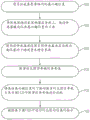
Fig. 11 is a flow chart illustrating a method of using a sensor delivery device according to some embodiments of the invention. In a preferred embodiment of the invention, the method may be used, for example, to assess the severity of stenotic lesions in a blood vessel of a patient. Step 1105 includes the feeling of placing a guidewire in a patientA location of interest. In some embodiments, this may be a diagnostic guidewire, and a guide catheter may also be inserted into the patient in conjunction with the guidewire. Step 1110 includes deploying a sensor delivery device over the guidewire and out of the guide catheter such that the sensor is positioned downstream of the location of interest (e.g., downstream of the stenotic lesion). In some embodiments, the sensor delivery device will have a sensor mounted to a distal sleeve that slides over the guidewire, and a proximal portion that is used to advance the distal sleeve over the guidewire without moving the guidewire. Step 1115 includes measuring a physiological parameter of interest at the location of interest using a sensor of the sensor delivery device. In some embodiments, the physiological parameter is blood pressure P downstream of the stenotic lesiond. Step 1120 includes measuring a reference value of the physiological parameter of interest. In some embodiments, this step includes measuring the blood pressure P upstream of the stenotic lesionp. This may be done, for example, with a separate blood pressure monitoring device according to some embodiments, or may be done by repositioning the sensor delivery device to a position upstream of the stenotic lesion and taking a second pressure measurement with the sensor of the device. In some embodiments, the sensor may be positioned within the lumen of the guide catheter to measure Pp. Step 1125 can be an optional step that includes comparing the physiological parameter of interest measured at the location of interest with the reference value measured in step 1120. In some embodiments, this may include calculating a ratio of the two measurements. In a preferred embodiment of the present invention, step 1125 includes calculating FFR as the ratio P of the downstream blood pressure to the upstream blood pressured/Pp. Step 1130 may be an optional step that includes providing an indication of the results obtained in step 1125. For example, step 1130 may include providing a visual indication of the calculated FFR value, or may provide other visual cues (e.g., providing a color-coded indication of stenosis severity, such as marked with a red indicator for FFR values less than 0.75, as possible examples, and for FFR values equal to or greater than 0.75Marked with a green indicator).
As mentioned above with reference to fig. 8, it may be desirable to have the sensor delivery device 210 interact with other devices and/or display devices. For example, the prongs 290 and the connector 294 may be used to send signals (e.g., measured physiological parameter signals) from the sensor 240 to the processing device 296. The processing device 296 may be, for example, a stand-alone display monitor for showing a signal waveform and/or showing multiple values of a physiological parameter signal from the sensor 240. In some embodiments, the processing arrangement 296 may include data logging capabilities. In certain preferred embodiments of the present invention, the processing device 296 may include a medical fluid injection system, such as a motorized fluid injector for injecting contrast media and/or saline in certain imaging procedures (e.g., angiography, computed tomography, MRI, ultrasound, etc.). Fig. 12 and 13 illustrate an exemplary motorized infusion system that can be used with a sensor delivery device according to various embodiments of the present invention.
Fig. 12 is a perspective view of one embodiment of a motorized infusion system 1200 that can be used to perform multiple functions and that can be operably coupled with a physiological sensor delivery device (e.g., the multiple embodiments of sensor delivery devices described above). The powered injection system 1200 shown in fig. 12 may be used to inject a medical fluid, such as contrast media or saline, into a patient in a sterile field during a medical procedure, such as during an angiographic or CT procedure. According to one embodiment, the physiological sensor delivery device may be coupled to the system 1200 and used within a sterile field during patient handling. System 1200 includes a number of different components, such as a control panel 1202, a manual controller connection 1204, a manual controller 1212, a fluid reservoir 1206, a tube 1208, a pump 1210, a pressure transducer 1218, a fluid reservoir 1214, an injector 1216, a high pressure syringe 1222, a valve 1220, an air detector 1224, and a stopcock 1226. In one embodiment, described in more detail below, the fluid reservoir 1206 comprises a container, such as, for example, a bag or bottle of diluent (e.g., saline), the fluid reservoir 1214 comprises a container, such as, for example, a bag or bottle of contrast media, and the pump 1210 comprises a peristaltic pump. In other embodiments, the pump 1210 may include other forms of pumping devices, such as syringes, gear pumps, or other forms of positive displacement pumps. In some embodiments, the syringe 1216 (along with its associated plunger) as a pumping device may be replaced with another form of pumping device that delivers a high pressure fluid injectate to the patient. The individual pumping devices can be operated or function in different or multiple modes of operation. For example, the pumping device may be operable to pump fluid to move in a first direction (e.g., forward) when actuated or driven, while it may also be operable to move in a second direction (e.g., reverse, backward) to perform certain functions.
The system 1200 of FIG. 12 also shows a manual controller 1212 and an air detector 1224. The operator may manually control the injection of saline and/or contrast media using the manual controller 1212. The operator may, for example, push a first button (not shown) on the manual controller 1212 to inject saline and may push a second button (not shown) to inject contrast media. In one embodiment, the operator may push the contrast button to deliver contrast at a variable flow rate. The harder the operator pushes the button, the greater the flow rate of contrast media delivered to the patient. Other controls, such as a foot pedal control, may also be used. The air detector 1224 is capable of detecting potential air bubbles or columns within the high pressure line 1222. In one embodiment, the air detector 1224 is an ultrasonic-based or acoustic detector. In other embodiments, the air detector 1224 may use infrared or other detection devices (e.g., optics). If the air detector 1224 detects the presence of air in the high pressure line 1222, it will generate a signal to alert an operator and/or to halt the injection procedure.
The operator may use the control panel 1202 to view and/or select various parameters and/or protocols to be used during a given procedure. The control panel 1202 may be used to display information to the operator regarding the status of the device and/or patient. The pump 1210 may be used to pump saline from the bag into the patient via the saline line 1208, the valve 1220, and the high pressure line 1222. In one embodiment, valve 1220 comprises a spring-based spool valve, as is known in the art. In one embodiment, the valve 1220 comprises an elastomer-based valve.
In one embodiment, a syringe 1216 is used to draw contrast from the reservoir 1214 into the syringe 1216 and to inject contrast from the syringe 1216 into the patient via the valve 1220 and high pressure line 1222. In one embodiment, the syringe 1216 is a self-flushing syringe having one port for filling with contrast and air flushing and having a second port for injecting contrast.
The valve 1220 may be used to control the coupling between multiple input ports and one output port to the valve 1220. In one embodiment, the valve includes two input ports, one of which is coupled to the contrast fluid line and the other of which is coupled to the saline fluid line. The saline fluid line includes a pressure transducer 1218 for providing a signal indicative of the patient's blood pressure, for example.
As described above, the system 1200 of fig. 12 may be adapted to be coupled to a physiological sensor delivery device according to some embodiments of the present invention. The system 1200 may, for example, be adapted to receive physiological signals generated by the sensors 240 of the apparatus 210. The physiological signal from device 210 is a pressure signal (e.g., P) measured downstream of the stenotic lesiond) In various embodiments, the system 1200 may conveniently calculate, for example, FFR because the pressure transducer 1218 of the system 1200 may already provide Pp. A visual or graphical display of the calculated FFR value may be presented to the operator, for example, via control panel 1202. Due to PpAnd PdIs obtainable in such an arrangement, the timing effects and associated errors described above with respect to fig. 3 will not cause the problem-PpAnd PdSimultaneous measurement of the same will reduce or eliminate such errors. Further, the system 1200 may utilize time averaging or other signal processing to generate mathematical variants of the FFR calculation (e.g., average, maximum, minimum, etc.). Alternatively, a time varying graph of the displayed or calculated FFR value may be displayed as a waveform (e.g., time varying).
Fig. 13 is a perspective view of another embodiment of a motorized infusion system 1300 that can be used to perform multiple functions and that can be operably coupled with a physiological sensor delivery device, such as the embodiments described above. The powered injection system 1300 shown in fig. 13 may be used to inject a medical fluid, such as contrast media or saline, into a patient in a sterile field during a medical procedure, such as during an angiographic or CT procedure. According to one embodiment, the physiological sensor delivery device may be coupled to the system 1300 and used within a sterile field during patient handling.
The system 1300 of fig. 13 is a dual injector system that includes a control panel 1302 and two motor/ actuator assemblies 1303a and 1303 b. Each motor drives one of the linear actuators in these assemblies 1303a, 1303 b. Each linear actuator drives the plunger of one syringe 1308a and 1308 b. The individual plungers move in a forward or rearward direction within the syringe barrels of the syringes 1308a and 1308 b. When moved in the forward direction, the plunger injects liquid into the patient line or pushes air out of the syringe and into a liquid container (e.g., a bottle). When moved in the rearward direction, the plunger fills liquid from the liquid container into the syringe 1308a, 1308 b. Fig. 13 shows an example of two such liquid containers 1304 and 1306. In one embodiment, container 1304 is a bag or bottle containing contrast media and container 1306 is a bag or bottle containing a diluent (e.g., saline). In other embodiments, the syringes 1308a, 1308b (along with associated plungers) each being a pumping device may individually or together comprise another form of pumping device capable of injecting fluid at an appropriate flow rate/pressure/etc., such as, for example, a peristaltic pump or another form of positive displacement pump. The individual pumping devices can be operated or function in different or multiple modes of operation. For example, the pumping device may be operable to pump fluid to move in a first direction (e.g., forward) when actuated or driven, while it may also be operable to move in a second direction (e.g., reverse, backward) to perform certain functions. Sets of pinch valve/air detection assemblies are shown in FIG. 13. One pinch valve/air detect assembly 1310a is coupled between the liquid container 1306 and the injection input port of the syringe 1308a, and a second pinch valve/air detect assembly 1312a is coupled between the injection output port of the syringe 1308a and the patient connection. A third pinch valve/air detect assembly 1310b is coupled between the liquid container 1304 and an injection input port of the syringe 1308b, and a fourth pinch valve/air detect assembly 1312b is coupled between an injection output port of the syringe 1308b and the patient connection. In the embodiment shown in FIG. 13, each syringe 1308a, 1308b is a dual port syringe. Fluid flows into and is drawn into the syringe 1308a or 1308b from the container via the injection input port, and fluid flows or is injected from the syringe 1308a or 1308b via the injection output port.
Each pinch valve is a pinch valve/air detect assembly 1310a, 1310b, 1312a, 1312b that can be opened or closed by the system 1300 to control the fluid connection to or from each syringe 1308a, 1308 b. The air detection sensors in the assemblies 1310a, 1310b, 1312a, 1312b may be optical, acoustic, or other forms of sensors. These sensors help detect air that may be present in the fluid connection leading to or from the syringes 1308a, 1308 b. When one or more of these sensors generate a signal indicating that air may be present in the fluid line, the system 1300 may alert the user or terminate the injection procedure. The use of multiple pinch valves within the system 1300 allows the system 1300, either automatically or through user interaction, to selectively control the flow of fluid into or out of the syringes 1308a, 1308b by opening or closing the fluid line. In one embodiment, system 1300 controls each of these pinch valves. The use of multiple air detection sensors helps to improve the overall safety of the system 1300 by detecting possible air (e.g., air columns, bubbles) within the fluid (in the tubing) leading to or exiting the syringes 1308a, 1308 b. Signals from these air detectors are sent to and processed by the system 1300 so that the system 1300 can, for example, provide an alert or terminate an injection procedure if an air condition is detected. In the example of fig. 13, the fluid line first flows through the pinch valve and then through the air detector within the assemblies 1310a, 1310b, 1312a, 1312 b. In other embodiments, other configurations, sequences, etc. may be used for the pinch valves and air detectors within these assemblies. Furthermore, other types of valves may be used in place of the pinch valve.
An operator may use the control panel 1302 to initialize or set the injection system 1300 for one or more injection procedures, and may additionally use the control panel 1302 to configure one or more parameters (e.g., flow rate, volume of fluid to be delivered, pressure limit, rise time) of an individual injection procedure. The operator may also use the panel 1302 to pause, continue, or end the injection procedure and start a new procedure. The control panel also displays to the operator a variety of different infusion related information such as flow rate, volume, pressure, rise time, procedure type, fluid information, and patient information. In one embodiment, the control panel 1302 may be connected to the examination couch while being electrically coupled to the main injector of the system 1300. In this embodiment, an operator may manually move the control panel 1302 to a desired position while still having access to all of the functionality provided by the panel 1302.
The system of FIG. 13 also includes a valve 1314 coupled to the two output lines from the syringes 1308a and 1308 b. Each syringe outlet provides injected fluid through tubing that passes through the pinch valve/air detect assembly 1312a or 1312b and then to the inlet of the valve 1314. In one embodiment, one fluid line to valve 1314 also includes a pressure transducer. The valve output port of the valve 1314 is coupled to a high pressure line for directing fluid to the patient. In one embodiment, the valve 1314 is made of a flexible material, such as an elastomeric material. The valve 1314 allows one of these fluid lines (e.g., contrast media line or saline line) to be coupled to a patient (high pressure line) line. When saline and contrast media are contained within the syringes 1308a and 1308b, respectively, the valve 1314 allows the contrast media to flow from the syringe 1308b to the patient line (assuming the pinch valve in the assembly 1312b is open and no air is detected), but blocks the flow of saline from the syringe 1308a to the patient line. The pressure transducer coupled to the saline line (according to one embodiment) is also isolated from the patient line, thereby protecting the sensor from the high injection pressures that may accompany contrast injection. When no contrast is being injected from the syringe 1308b, the valve 1314 blocks the contrast line from the patient line, but allows connection between the saline line from the syringe 1306 and the patient line. The syringe 1308a can inject saline into the patient (assuming that the pinch valve in the assembly 1312a is open and no air is detected) and the pressure transducer can also monitor hemodynamic signals from the patient via the patient line and generate representative electronic signals based on the measured pressure that can be processed by the system 1300.
In one embodiment, a secondary control panel (not shown) provides a subset of the functionality provided by the main panel 1302. This secondary control panel (also referred to herein as a "small" control panel) may be coupled to the injector within the system 1300. In one case, the operator may use the small control panel to manage the injector settings. The small panel may display guidance setup instructions that assist this process. The small panel may also display certain error and debug information to assist the operator. For example, the small panel may alert the operator that the fluid level of contrast or saline in the fluid reservoirs and/or the injector is low.
As with the system 1200 of fig. 12, the system 1300 of fig. 13 may be adapted to couple a physiological sensor delivery device according to some embodiments of the present invention. The system 1300 may, for example, be adapted to receive physiological signals generated by the sensors 240 of the apparatus 210. Processing of physiological signals from the sensor 240 (and/or from additional sensors of the sensor delivery device 210, if applicable) may be performed within the infusion system 1200 or 1300. Signal conditioning and/or processing may be performed, for example, by a circuit board or card that may be an additional feature of system 1200 or 1300. According to some embodiments of the invention, such a signal conditioning board or card may process the "raw" signal from the sensor 240 and convert the signal to standard analog and/or digital signals that may be used by the processor of the injector system. The processed signals enable the injector system 1200 or 1300 to display the signal data (e.g., as a pressure waveform), and/or perform arithmetic and/or calculations and display the results.
The physiological signal from device 210 is a pressure signal (e.g., P) measured downstream of the stenotic lesiond) In various embodiments, system 1300 may conveniently calculate FFR, for example, because the pressure transducer of system 1300 already provides Pp. A visual or graphical display of, for example, the calculated FFR value may be presented to the operator via, for example, control panel 1302, or via a small control panel (not shown) having a subset of these functions provided by control panel 1302. Due to PpAnd PdIs available in such an arrangement, the timing effects described above with respect to fig. 3 will not cause problems. In addition, system 1300 can utilize time averaging or other signal processing to generate an FFR meterMathematical variants of the calculation (e.g., mean, maximum, minimum, etc.).
FIG. 14 is a flow diagram of a method that may be implemented in accordance with an embodiment of the invention. The methods described herein may be performed with varying degrees of automation, for example, by storing instructions in a computer readable medium and/or executing the instructions with a computer or processor associated with an electrically powered injection system (e.g., those described above with respect to fig. 12 and 13, or other comparable fluid injection systems). According to some embodiments of the invention, the method of FIG. 14 may be used, for example, to assess the severity of fluid flow restrictions in a patient. This method may be performed using a plurality of different electrokinetic injection systems, such as the system 1200 shown in fig. 12 or the system 1300 shown in fig. 13. The order of these actions shown in FIG. 14 is for illustration purposes only. In one embodiment, the powered injection system may be capable of performing some of the steps of the method shown in fig. 14 automatically, or alternatively, after an operator has requested that the method be initiated by requesting on the control panel (or auxiliary panel, if available).
FIG. 15 is a flow diagram of a method that may be implemented in accordance with an embodiment of the invention. According to some embodiments of the invention, the method of fig. 15 may be used, for example, to assess the severity of fluid flow restrictions in a patient. The method of fig. 15 employs a sensor delivery device 210 having first and second sensors 240, 242, such as the device 210 shown in fig. 2 and 7. This method may also be performed in conjunction with a number of different electrokinetic injection systems, such as the system 1200 shown in fig. 12 or the system 1300 shown in fig. 13. The order of these actions shown in FIG. 15 is for illustration purposes only.
Although not shown in fig. 11, 14, and 15, any of these methods may be practiced with embodiments of the device 210 having a plurality of flow apertures 224, such as fig. 4(a) and 4 (b). Using such devices, the methods may optionally include the steps of: where the operator retracts the guidewire 230 to allow fluid flow (e.g., blood flow) through the flow aperture 224 into the guidewire lumen 222 of the distal cannula 220. At measuring downstream pressure PdPerforming this optional step previously may reduce the amount of flow restriction caused by the device 210 itself, and thus may reduce measurement error.
In some embodiments, a method may include making a treatment decision based on the calculated FFR value, e.g., recommending and/or performing an interventional procedure if the calculated FFR is less than 0.75. In some embodiments, the interventional device may be deployed by withdrawing the sensor delivery device 210 and deploying the interventional device using the same guidewire 230.
Fig. 16 is a perspective view of an electro-kinetic infusion system adapted for coupling to a physiological sensor delivery device according to some embodiments of the present invention. Fig. 16 shows the sensor delivery device 210 connected to an electrically powered injection system 1630 via a forked tube 290 and a connector 294. The injection system 1630 is adapted to receive physiological measurement signals (e.g., blood pressure) from the device 210 via the input port 1650. In a preferred embodiment, the signal is an optical signal and the connector 294 is an SC fiber optic connector adapted to mate with the port 1650 to receive the optical signal.
As shown in fig. 16, system 1630 has 2 fluid containers 1632, 1634 adapted to deliver fluid through lines 1633 and 1635. The fluid in line 1633 (e.g., contrast solution) may be delivered, for example, at a significantly higher pressure than the fluid in line 1635 (e.g., saline solution). The valve 1620 may be used to control the coupling between the input port to the valve 1620 and to the output port, which ultimately leads to the patient via a patient line 1622. In one embodiment, valve 1620 includes two input ports, one of which is coupled to contrast fluid line 1633 and the other of which is coupled to saline fluid line 1635. The saline fluid line is also coupled to a pressure transducer 1618 for providing a signal indicative of, for example, the patient's blood pressure. Signals from pressure transducer 1618 may be communicated to system 1630 via communication path 1640 and connector 1642, or via other equivalent devices (e.g., infrared, optical, etc.).
In one embodiment, the valve 1620 allows the saline or contrast line to be coupled to the patient (high pressure line) line 1622. When the system 1630 is injecting contrast media, the valve 1620 may allow the contrast media to flow to the patient line 1622 while preventing the physiological saline from flowing to the patient line 1622. The valve 1620 may operate such that the pressure transducer 1618 may also be blocked or isolated from the patient line 1622 during a high pressure injection, for example, to protect the sensor 1618 from high injection pressures that may accompany a contrast media injection. When no contrast media is being injected from the system 1630, the valve 1620 may be operated to block the contrast media line from the patient line 1622 while opening a fluid connection between the saline line (tube) 1635 and the patient line 1622. In this state, the system 1630 can infuse saline into the patient, while the pressure transducer 1618 can detect hemodynamic signals from the patient via the patient line 1622 and generate a representative signal based on the measured pressure.
FIG. 16 shows the control panel 1602 coupled to the injection system 1630 via a communication path 1660. An operator may interact with the system 1630 via the control panel 1602 (or via an auxiliary panel, if available) to review and/or modify injection parameters, for example. In a preferred embodiment of the present invention, the system 1630 is adapted to receive the downstream pressure and the upstream pressure (e.g., P) from the pressure transducer 1618 and from the device 210, respectively, simultaneouslyd、Pp) The pressure signal of (a). Thus, in the preferred embodiment, system 1630 receives P substantially simultaneouslydAnd PpComparing the two signals (e.g., calculating FFR ═ P)d/Pp) And provides an indication of the comparison to the operator via display 1670 of control panel 1602. As noted above, the indication of the comparison may take a number of different forms, including numbers, graphs, time plots, and the like. The indication may have a pass/fail classification, such as indicating one color-coded pattern (e.g., a red icon) for FFR values below a certain value (e.g., 0.75), and/or indicating a different color-coded pattern (e.g., a green icon) for FFR values equal to or above a certain value (e.g., 0.75). The indication may also be an audible alarm according to some embodiments of the invention.
FIG. 17 is an idealized view of information that may be presented (e.g., via an interactive graphical user interface, or "GUI interface") to an operator, according to some embodiments of the invention. Fig. 17 shows a GUI screen that may be displayed via a control panel dedicated to sensor delivery device 210 or via a control panel of a device adapted for use with device 210, such as the powered fluid injection system described above with reference to fig. 12, 13, and 16. (according to various embodiments of the invention, the GUI interface may be implemented in software so that the user can see very similar screens, whether using a separate display device or an integrated injector system.)
In fig. 17, the screen 1702 is adapted to display data in different forms (e.g., waveform data, numerical data, calculated values, patient information, device status information, etc.). For example, in a preferred embodiment of the invention useful for making FFR measurements, the proximal pressure P may be referencedp(t)1704 and distal pressure Pd(t)1706 both show the blood pressure waveform over time. In some embodiments, systolic and diastolic blood pressure measurements may be superimposed on the time plot of the proximal (e.g., aortic) pressure waveform, as shown at 1708 and 1710, respectively, and/or may be calculated as an average and displayed approximately at 1712 as shown. Similarly, the average of the proximal pressure 1704 and distal pressure 1706 may be calculated (e.g., these may be time weighted averages, moving averages, etc.) and displayed as shown at 1714 and 1716, respectively. According to some embodiments of the invention, the calculation of FFR based on proximal pressure 1704 and distal pressure 1706 may also be calculated and displayed, for example, at 1718 as shown (e.g., FFR equals Pp/PdAnd is used for PpAnd PdThe value of (d) may be an average or other form of statistical and numerical representation). Additionally, some embodiments may include a feature that alerts the operator that the FFR value is outside of a normal range (e.g., less than 0.75) for indicating, for example, that some other action should be taken (e.g., selecting and performing an interventional procedure). This may be a visual cue (e.g., a colored light, as shown at 1720) or may be an audible cue (e.g., like an alarm sound).
The screen 1702 of fig. 17 may also include navigation features that may allow the operator to view and record information that may be of interest in some embodiments. For example, a cursor button 1726 may allow an operator to position a marker or cursor 1727 on a point of interest on the waveforms 1704, 1706, which may provide P at a selected point in timep(t)1704 and Pd(t) instantaneous measurements at 1706. In some embodiments, the operator may choose to save this tabbed data by pressing a "save" button 1728, which may save important data for later review. In some embodiments, a review button 1730 may be provided for this purpose for allowing the user to compare previous historical measurements to current values and use this information for diagnostic and therapeutic decisions. In some embodiments, it may be desirable to include a "zoom" feature, for example, for analyzing data. For example, the operator may want to zoom in (e.g., via zoom 1732 arrow +) at certain data to more specifically view, or may instead want to zoom out (e.g., via zoom 1732 arrow-) to evaluate the overall trend, for example.
The physiological sensor delivery device has been described in connection with exemplary embodiments and exemplary preferred embodiments and implementations, by way of example only. It will be appreciated by those of ordinary skill in the art that modifications can be readily made to any of these embodiments or the preferred embodiments without materially departing from the scope of the appended claims.
Claims (4)
1. A sensor delivery device, comprising:
a distal sleeve configured to be advanced over a guidewire through a patient's blood vessel, the distal sleeve including a distal sensor located on the distal sleeve, a proximal sensor located on the distal sleeve and proximal to the distal sensor, a proximal portion, and a communication channel, the sensors adapted to generate a signal proportional to fluid pressure,
wherein one or both of the distal sensor and the proximal sensor comprises a material having a low thermal coefficient of pressure, and wherein said material having a low thermal coefficient of pressure is configured to allow the sensor to be calibrated to atmospheric pressure outside the patient's body at approximately room temperature, and still calibrated to atmospheric pressure after insertion into the patient's body.
2. The sensor delivery device of claim 1, wherein the thermal coefficient of pressure of the material is between approximately-0.1 and 0.1mmHg/° c.
3. The sensor delivery device of claim 1, wherein the proximal sensor and distal sensor each comprise a material having a low thermal coefficient of pressure.
4. The sensor delivery device of claim 1, further comprising a guidewire and a guide catheter.
Applications Claiming Priority (3)
| Application Number | Priority Date | Filing Date | Title |
|---|---|---|---|
| US14/300,654 US10244951B2 (en) | 2014-06-10 | 2014-06-10 | Physiological sensor delivery device and method |
| US14/300,654 | 2014-06-10 | ||
| PCT/US2015/034830 WO2015191531A1 (en) | 2014-06-10 | 2015-06-09 | Physiological sensor delivery device and method |
Publications (2)
| Publication Number | Publication Date |
|---|---|
| CN107072557A CN107072557A (en) | 2017-08-18 |
| CN107072557B true CN107072557B (en) | 2020-06-09 |
Family
ID=53434503
Family Applications (1)
| Application Number | Title | Priority Date | Filing Date |
|---|---|---|---|
| CN201580031127.2A Active CN107072557B (en) | 2014-06-10 | 2015-06-09 | Physiological sensor delivery devices and methods |
Country Status (5)
| Country | Link |
|---|---|
| US (2) | US10244951B2 (en) |
| EP (1) | EP3154421A1 (en) |
| JP (3) | JP6606107B2 (en) |
| CN (1) | CN107072557B (en) |
| WO (1) | WO2015191531A1 (en) |
Families Citing this family (13)
| Publication number | Priority date | Publication date | Assignee | Title |
|---|---|---|---|---|
| US10244951B2 (en) * | 2014-06-10 | 2019-04-02 | Acist Medical Systems, Inc. | Physiological sensor delivery device and method |
| US10993629B2 (en) * | 2015-04-23 | 2021-05-04 | Regents Of The University Of Minnesota | Multi-focal intravascular pressure catheter devices, systems and methods |
| WO2018022919A1 (en) * | 2016-07-28 | 2018-02-01 | Evalve, Inc. | Systems and methods for intra-procedural cardiac pressure monitoring |
| US20180263515A1 (en) * | 2017-03-16 | 2018-09-20 | Adventist Health System/Sunbelt, Inc. | Intravascular catheter with pressure sensors |
| WO2019151867A1 (en) * | 2018-01-31 | 2019-08-08 | Spiro Medical As | Medical catheter for temperature and pressure sensing and production method thereof |
| CN112703560A (en) * | 2018-05-29 | 2021-04-23 | B.布劳恩梅尔松根股份公司 | Peripheral venous catheter assembly with sensor and related methods |
| NL2021208B1 (en) * | 2018-06-29 | 2020-01-07 | Wellinq Medical B V | PRESSURE SENSOR MICROCATHETER SYSTEM, AND ASSOCIATED METHODS |
| US10794786B2 (en) * | 2018-09-24 | 2020-10-06 | Honeywell International Inc. | Miniature size force sensor with bubble detection capabilities |
| US11464485B2 (en) | 2018-12-27 | 2022-10-11 | Avent, Inc. | Transducer-mounted needle assembly with improved electrical connection to power source |
| US11647980B2 (en) | 2018-12-27 | 2023-05-16 | Avent, Inc. | Methods for needle identification on an ultrasound display screen by determining a meta-frame rate of the data signals |
| US11707563B2 (en) | 2019-09-06 | 2023-07-25 | Adventist Health System/Sunbelt, Inc. | Advanced dialysis catheter with pressure sensor |
| CN112426142B (en) * | 2019-12-31 | 2021-09-21 | 深圳北芯生命科技股份有限公司 | Intravascular pressure measurement system |
| CN111214215A (en) * | 2020-01-14 | 2020-06-02 | 深圳安特医疗股份有限公司 | Detection device and invasive pressure sensor |
Citations (3)
| Publication number | Priority date | Publication date | Assignee | Title |
|---|---|---|---|---|
| CN1681542A (en) * | 2002-08-16 | 2005-10-12 | 微芯片公司 | Controlled release device and method using electrothermal ablation |
| EP1599232A2 (en) * | 2003-02-21 | 2005-11-30 | Electro-Cat, LLC | System and method for measuring cross-sectional areas and pressure gradients in luminal organs |
| CN103674404A (en) * | 2012-09-07 | 2014-03-26 | 丹尼斯科工具有限公司 | Capacitive pressure sensor |
Family Cites Families (79)
| Publication number | Priority date | Publication date | Assignee | Title |
|---|---|---|---|---|
| US4006735A (en) | 1974-07-16 | 1977-02-08 | Hittman Corporation | Pressure sensor apparatus |
| JPS61235731A (en) * | 1985-04-11 | 1986-10-21 | Sharp Corp | Pressure sensing element |
| US4771782A (en) | 1986-11-14 | 1988-09-20 | Millar Instruments, Inc. | Method and assembly for introducing multiple catheters into a biological vessel |
| US4850358A (en) | 1986-11-14 | 1989-07-25 | Millar Instruments, Inc. | Method and assembly for introducing multiple devices into a biological vessel |
| US5046497A (en) | 1986-11-14 | 1991-09-10 | Millar Instruments, Inc. | Structure for coupling a guidewire and a catheter |
| US4966148A (en) | 1986-11-14 | 1990-10-30 | Millar Instruments, Inc. | Assembly for positioning diagnostic devices in a biological vessel |
| US4901731A (en) | 1988-04-27 | 1990-02-20 | Millar Instruments, Inc. | Single sensor pressure differential device |
| US5178159A (en) | 1988-11-02 | 1993-01-12 | Cardiometrics, Inc. | Torqueable guide wire assembly with electrical functions, male and female connectors rotatable with respect to one another |
| US4991590A (en) | 1989-01-30 | 1991-02-12 | Martin Goffman Associates | Fiber optic intravascular blood pressure transducer |
| US4928693A (en) | 1989-03-13 | 1990-05-29 | Schneider (Usa), Inc. | Pressure monitor catheter |
| US5395311A (en) | 1990-05-14 | 1995-03-07 | Andrews; Winston A. | Atherectomy catheter |
| SU1802695A3 (en) | 1991-02-07 | 1993-03-15 | Kokapeb Ahatoлий Mиxaйлobич | Apparatus for measuring central vein pressure |
| US5280786A (en) | 1992-01-21 | 1994-01-25 | Fiberoptic Sensor Technologies, Inc. | Fiberoptic blood pressure and oxygenation sensor |
| US5422478A (en) * | 1992-04-17 | 1995-06-06 | Fiberoptic Sensor Technologies, Inc. | Fiberoptic pressure sensor having drift correction means for insitu calibration |
| US5597377A (en) | 1994-05-06 | 1997-01-28 | Trustees Of Boston University | Coronary sinus reperfusion catheter |
| DE69534748T2 (en) | 1994-09-02 | 2006-11-02 | Volcano Corp. (n.d, Ges.d.Staates Delaware), Rancho Cordova | ULTRAMINIATUR PRESSURE SENSOR AND GUIDE WIRE THEREFORE |
| ES2205024T3 (en) | 1995-04-20 | 2004-05-01 | Acist Medical Systems, Inc. | ANGIOGRAPHIC INJECTOR. |
| SE9600333D0 (en) | 1995-06-22 | 1996-01-30 | Radi Medical Systems | Sensor arrangement |
| WO1997012210A1 (en) | 1995-09-29 | 1997-04-03 | Swee Chuan Tjin | Fiber optic catheter for accurate flow measurements |
| SE9600334D0 (en) | 1996-01-30 | 1996-01-30 | Radi Medical Systems | Combined flow, pressure and temperature sensor |
| US6146354A (en) | 1996-05-24 | 2000-11-14 | Horizon Medical Products | Asymmetrical multi-lumen apheresis catheter with balanced flow rates |
| US5782797A (en) | 1996-06-06 | 1998-07-21 | Scimed Life Systems, Inc. | Therapeutic infusion device |
| JPH10267775A (en) | 1997-03-25 | 1998-10-09 | Tokai Rika Co Ltd | Pressure sensor |
| US6248083B1 (en) | 1997-03-25 | 2001-06-19 | Radi Medical Systems Ab | Device for pressure measurements |
| US5938624A (en) | 1997-09-10 | 1999-08-17 | Radi Medical Systems Ab | Male connector with a continous surface for a guide wire and method therefor |
| JPH11188010A (en) | 1997-10-21 | 1999-07-13 | Kawasumi Lab Inc | Catheter with pressure sensor |
| US6295990B1 (en) | 1998-02-03 | 2001-10-02 | Salient Interventional Systems, Inc. | Methods and systems for treating ischemia |
| JP3116032B2 (en) | 1998-02-27 | 2000-12-11 | 日本ビー・エックス・アイ株式会社 | Guidewire blood flow meter |
| US6089103A (en) | 1998-05-06 | 2000-07-18 | Radi Medical Systems Ab | Method of flow measurements |
| US6245053B1 (en) | 1998-11-09 | 2001-06-12 | Medtronic, Inc. | Soft tip guiding catheter and method of fabrication |
| US6471656B1 (en) | 1999-06-25 | 2002-10-29 | Florence Medical Ltd | Method and system for pressure based measurements of CFR and additional clinical hemodynamic parameters |
| EP1251769A1 (en) | 1999-03-09 | 2002-10-30 | Florence Medical Ltd. | A method and system for pressure based measurements of cfr and additional clinical hemodynamic parameters |
| JP4191849B2 (en) | 1999-05-28 | 2008-12-03 | 泉工医科工業株式会社 | Balloon catheter |
| US6383144B1 (en) | 2000-01-18 | 2002-05-07 | Edwards Lifesciences Corporation | Devices and methods for measuring temperature of a patient |
| US6672172B2 (en) * | 2000-01-31 | 2004-01-06 | Radi Medical Systems Ab | Triggered flow measurement |
| EP1409057B1 (en) | 2000-12-12 | 2008-09-24 | Datascope Investment Corp. | Intra-Aortic balloon catheter having a fiberoptic sensor |
| US6616597B2 (en) | 2000-12-12 | 2003-09-09 | Datascope Investment Corp. | Intra-aortic balloon catheter having a dual sensor pressure sensing system |
| US20020072679A1 (en) | 2000-12-12 | 2002-06-13 | Schock Robert B. | Intra-aortic balloon catheter having a fiberoptic sensor |
| US6585660B2 (en) | 2001-05-18 | 2003-07-01 | Jomed Inc. | Signal conditioning device for interfacing intravascular sensors having varying operational characteristics to a physiology monitor |
| US7329223B1 (en) | 2001-05-31 | 2008-02-12 | Abbott Cardiovascular Systems Inc. | Catheter with optical fiber sensor |
| WO2002101347A1 (en) | 2001-06-08 | 2002-12-19 | Radi Medical Systems Ab | Miniaturized pressure sensor |
| US7611503B2 (en) | 2004-04-16 | 2009-11-03 | Medrad, Inc. | Fluid delivery system, fluid path set, sterile connector and improved drip chamber and pressure isolation mechanism |
| US8668650B2 (en) * | 2001-12-20 | 2014-03-11 | Boston Scientific Scimed, Inc. | Pressure-sensing guidewire and sheath |
| US6868736B2 (en) | 2002-02-22 | 2005-03-22 | Sentec Corporation | Ultra-miniature optical pressure sensing system |
| US7134994B2 (en) | 2002-05-20 | 2006-11-14 | Volcano Corporation | Multipurpose host system for invasive cardiovascular diagnostic measurement acquisition and display |
| US6819951B2 (en) | 2002-09-24 | 2004-11-16 | Mayo Foundation For Medical Education And Research | Peripherally inserted central catheter with continuous central venous oximetry and proximal high flow port |
| US8712549B2 (en) | 2002-12-11 | 2014-04-29 | Proteus Digital Health, Inc. | Method and system for monitoring and treating hemodynamic parameters |
| JP4338446B2 (en) | 2003-06-05 | 2009-10-07 | 株式会社根本杏林堂 | Chemical injection device |
| JP4137740B2 (en) | 2003-08-06 | 2008-08-20 | オリンパス株式会社 | Capsule type medical device and capsule type medical device guidance system |
| DE10342709A1 (en) | 2003-09-11 | 2005-04-21 | Biotronik Gmbh & Co Kg | catheter |
| JP4554967B2 (en) | 2004-03-25 | 2010-09-29 | テルモ株式会社 | Ultrasonic catheter and diagnostic imaging apparatus |
| JP2005291945A (en) | 2004-03-31 | 2005-10-20 | Masaki Esashi | Sensor device |
| US8277386B2 (en) | 2004-09-27 | 2012-10-02 | Volcano Corporation | Combination sensor guidewire and methods of use |
| US7689071B2 (en) | 2004-12-22 | 2010-03-30 | Opsens Inc. | Fiber optic pressure sensor for catheter use |
| RU47203U1 (en) | 2005-04-08 | 2005-08-27 | Институт радиотехники и электроники РАН г.Москва | FIBER OPTICAL THERMOMETER |
| US7771362B2 (en) * | 2005-08-01 | 2010-08-10 | Datascope Investment Corp. | Calibration of in vivo blood pressure sensors |
| JP5129749B2 (en) | 2005-09-30 | 2013-01-30 | コルノヴァ インク | System for probe inspection and treatment of body cavities |
| US7775988B2 (en) * | 2005-09-30 | 2010-08-17 | Radi Medical Systems Ab | Method for determining the blood flow in a coronary artery |
| US20070255145A1 (en) | 2006-04-28 | 2007-11-01 | Radi Medical Systems Ab | Sensor and guide wire assembly |
| US7724148B2 (en) | 2006-11-20 | 2010-05-25 | Radi Medical Systems Ab | Transceiver unit in a pressure measurement system |
| JP5746969B2 (en) | 2008-09-11 | 2015-07-08 | アシスト・メディカル・システムズ,インコーポレイテッド | Physiological sensor delivery device and fluid injection system |
| US8317715B2 (en) | 2009-03-17 | 2012-11-27 | Opsens Inc. | Eccentric pressure catheter with guidewire compatibility |
| JP5922111B2 (en) | 2010-06-23 | 2016-05-24 | ピーツー−サイエンス・エペイエス | A composite arterial catheter for diagnostic purposes that measures blood pressure at the same time as infusion of a hyperemia |
| GB201100136D0 (en) * | 2011-01-06 | 2011-02-23 | Davies Helen C S | Apparatus and method of characterising a narrowing in a filled tube |
| US9259161B2 (en) | 2011-05-11 | 2016-02-16 | Acist Medical Systems, Inc. | Intravascular sensing method and system |
| US9339348B2 (en) | 2011-08-20 | 2016-05-17 | Imperial Colege of Science, Technology and Medicine | Devices, systems, and methods for assessing a vessel |
| WO2013109815A1 (en) | 2012-01-19 | 2013-07-25 | Volcano Corporation | Interface devices, systems, and methods for use with intravascular pressure monitoring devices |
| JP6220868B2 (en) | 2012-05-25 | 2017-10-25 | ヴァスキュラー イメージング コーポレイションVascular Imaging Corporation | Fiber optic pressure sensor |
| US9241641B2 (en) | 2012-07-20 | 2016-01-26 | Acist Medical Systems, Inc. | Fiber optic sensor assembly for sensor delivery device |
| WO2014025255A1 (en) | 2012-08-06 | 2014-02-13 | Wellinq Medical B.V. | Pressure sensor catheter and associated method |
| JP6419425B2 (en) * | 2012-11-29 | 2018-11-07 | キヤノンメディカルシステムズ株式会社 | Blood flow function testing apparatus and X-ray diagnostic apparatus |
| WO2014099942A1 (en) | 2012-12-21 | 2014-06-26 | Volcano Corporation | Display control for a multi-sensor medical device |
| CN203458373U (en) * | 2013-09-10 | 2014-03-05 | 南方医科大学 | Real-time measurement system for fractional coronary flow reserve |
| US9877660B2 (en) * | 2013-11-14 | 2018-01-30 | Medtronic Vascular Galway | Systems and methods for determining fractional flow reserve without adenosine or other pharmalogical agent |
| US9913585B2 (en) * | 2014-01-15 | 2018-03-13 | Medtronic Vascular, Inc. | Catheter for providing vascular pressure measurements |
| US10244951B2 (en) * | 2014-06-10 | 2019-04-02 | Acist Medical Systems, Inc. | Physiological sensor delivery device and method |
| EP3355771B1 (en) | 2015-09-29 | 2020-11-11 | Imperial Innovations Ltd | System for coronary intervention assessment, planning, and treatment based on desired outcome |
| CN105326486B (en) | 2015-12-08 | 2017-08-25 | 博动医学影像科技(上海)有限公司 | Vascular pressure difference and the computational methods and system of blood flow reserve fraction |
| EP3484351A4 (en) * | 2016-07-15 | 2020-02-26 | Gate Scientific, Inc. | Electronic single use chemical diagnostics device |
-
2014
- 2014-06-10 US US14/300,654 patent/US10244951B2/en active Active
-
2015
- 2015-06-09 CN CN201580031127.2A patent/CN107072557B/en active Active
- 2015-06-09 EP EP15730370.2A patent/EP3154421A1/en not_active Ceased
- 2015-06-09 JP JP2016571724A patent/JP6606107B2/en active Active
- 2015-06-09 WO PCT/US2015/034830 patent/WO2015191531A1/en active Application Filing
-
2019
- 2019-02-14 US US16/275,433 patent/US11826128B2/en active Active
- 2019-10-17 JP JP2019190122A patent/JP2020072868A/en active Pending
-
2021
- 2021-10-14 JP JP2021168923A patent/JP2022009151A/en active Pending
Patent Citations (3)
| Publication number | Priority date | Publication date | Assignee | Title |
|---|---|---|---|---|
| CN1681542A (en) * | 2002-08-16 | 2005-10-12 | 微芯片公司 | Controlled release device and method using electrothermal ablation |
| EP1599232A2 (en) * | 2003-02-21 | 2005-11-30 | Electro-Cat, LLC | System and method for measuring cross-sectional areas and pressure gradients in luminal organs |
| CN103674404A (en) * | 2012-09-07 | 2014-03-26 | 丹尼斯科工具有限公司 | Capacitive pressure sensor |
Also Published As
| Publication number | Publication date |
|---|---|
| US11826128B2 (en) | 2023-11-28 |
| US20190175032A1 (en) | 2019-06-13 |
| CN107072557A (en) | 2017-08-18 |
| JP2020072868A (en) | 2020-05-14 |
| JP6606107B2 (en) | 2019-11-13 |
| WO2015191531A1 (en) | 2015-12-17 |
| JP2017522933A (en) | 2017-08-17 |
| EP3154421A1 (en) | 2017-04-19 |
| US10244951B2 (en) | 2019-04-02 |
| US20150351645A1 (en) | 2015-12-10 |
| JP2022009151A (en) | 2022-01-14 |
Similar Documents
| Publication | Publication Date | Title |
|---|---|---|
| US20210236002A1 (en) | Physiological sensor delivery device and method | |
| CN107072557B (en) | Physiological sensor delivery devices and methods | |
| WO2015073817A1 (en) | Multi-sensor lesion assessment device and method |
Legal Events
| Date | Code | Title | Description |
|---|---|---|---|
| PB01 | Publication | ||
| PB01 | Publication | ||
| SE01 | Entry into force of request for substantive examination | ||
| SE01 | Entry into force of request for substantive examination | ||
| GR01 | Patent grant | ||
| GR01 | Patent grant |