CN106999125B - Source-detector arrangement - Google Patents
Source-detector arrangement Download PDFInfo
- Publication number
- CN106999125B CN106999125B CN201580060997.2A CN201580060997A CN106999125B CN 106999125 B CN106999125 B CN 106999125B CN 201580060997 A CN201580060997 A CN 201580060997A CN 106999125 B CN106999125 B CN 106999125B
- Authority
- CN
- China
- Prior art keywords
- grating
- ray
- source
- detector arrangement
- pitch
- Prior art date
- Legal status (The legal status is an assumption and is not a legal conclusion. Google has not performed a legal analysis and makes no representation as to the accuracy of the status listed.)
- Active
Links
Images


Classifications
-
- A—HUMAN NECESSITIES
- A61—MEDICAL OR VETERINARY SCIENCE; HYGIENE
- A61B—DIAGNOSIS; SURGERY; IDENTIFICATION
- A61B6/00—Apparatus for radiation diagnosis, e.g. combined with radiation therapy equipment
- A61B6/02—Devices for diagnosis sequentially in different planes; Stereoscopic radiation diagnosis
- A61B6/03—Computerised tomographs
- A61B6/032—Transmission computed tomography [CT]
-
- A—HUMAN NECESSITIES
- A61—MEDICAL OR VETERINARY SCIENCE; HYGIENE
- A61B—DIAGNOSIS; SURGERY; IDENTIFICATION
- A61B6/00—Apparatus for radiation diagnosis, e.g. combined with radiation therapy equipment
- A61B6/40—Apparatus for radiation diagnosis, e.g. combined with radiation therapy equipment with arrangements for generating radiation specially adapted for radiation diagnosis
- A61B6/4035—Apparatus for radiation diagnosis, e.g. combined with radiation therapy equipment with arrangements for generating radiation specially adapted for radiation diagnosis the source being combined with a filter or grating
-
- A—HUMAN NECESSITIES
- A61—MEDICAL OR VETERINARY SCIENCE; HYGIENE
- A61B—DIAGNOSIS; SURGERY; IDENTIFICATION
- A61B6/00—Apparatus for radiation diagnosis, e.g. combined with radiation therapy equipment
- A61B6/40—Apparatus for radiation diagnosis, e.g. combined with radiation therapy equipment with arrangements for generating radiation specially adapted for radiation diagnosis
- A61B6/4064—Apparatus for radiation diagnosis, e.g. combined with radiation therapy equipment with arrangements for generating radiation specially adapted for radiation diagnosis specially adapted for producing a particular type of beam
- A61B6/4085—Cone-beams
-
- A—HUMAN NECESSITIES
- A61—MEDICAL OR VETERINARY SCIENCE; HYGIENE
- A61B—DIAGNOSIS; SURGERY; IDENTIFICATION
- A61B6/00—Apparatus for radiation diagnosis, e.g. combined with radiation therapy equipment
- A61B6/48—Diagnostic techniques
- A61B6/484—Diagnostic techniques involving phase contrast X-ray imaging
-
- G—PHYSICS
- G02—OPTICS
- G02B—OPTICAL ELEMENTS, SYSTEMS OR APPARATUS
- G02B5/00—Optical elements other than lenses
- G02B5/18—Diffraction gratings
- G02B5/1866—Transmission gratings characterised by their structure, e.g. step profile, contours of substrate or grooves, pitch variations, materials
-
- H—ELECTRICITY
- H01—ELECTRIC ELEMENTS
- H01J—ELECTRIC DISCHARGE TUBES OR DISCHARGE LAMPS
- H01J35/00—X-ray tubes
- H01J35/02—Details
- H01J35/14—Arrangements for concentrating, focusing, or directing the cathode ray
- H01J35/153—Spot position control
-
- G—PHYSICS
- G21—NUCLEAR PHYSICS; NUCLEAR ENGINEERING
- G21K—TECHNIQUES FOR HANDLING PARTICLES OR IONISING RADIATION NOT OTHERWISE PROVIDED FOR; IRRADIATION DEVICES; GAMMA RAY OR X-RAY MICROSCOPES
- G21K2207/00—Particular details of imaging devices or methods using ionizing electromagnetic radiation such as X-rays or gamma rays
- G21K2207/005—Methods and devices obtaining contrast from non-absorbing interaction of the radiation with matter, e.g. phase contrast
-
- H—ELECTRICITY
- H01—ELECTRIC ELEMENTS
- H01J—ELECTRIC DISCHARGE TUBES OR DISCHARGE LAMPS
- H01J2235/00—X-ray tubes
- H01J2235/08—Targets (anodes) and X-ray converters
- H01J2235/081—Target material
- H01J2235/082—Fluids, e.g. liquids, gases
-
- H—ELECTRICITY
- H01—ELECTRIC ELEMENTS
- H01J—ELECTRIC DISCHARGE TUBES OR DISCHARGE LAMPS
- H01J2235/00—X-ray tubes
- H01J2235/08—Targets (anodes) and X-ray converters
- H01J2235/086—Target geometry
-
- H—ELECTRICITY
- H01—ELECTRIC ELEMENTS
- H01J—ELECTRIC DISCHARGE TUBES OR DISCHARGE LAMPS
- H01J35/00—X-ray tubes
- H01J35/02—Details
- H01J35/14—Arrangements for concentrating, focusing, or directing the cathode ray
Abstract
The invention relates to a source-detector arrangement (11) for an X-ray device (10) for grating-type phase contrast computed tomography. The source-detector arrangement comprises: an X-ray source (12) adapted for rotational movement about a rotational axis (R) relative to an object (140) and adapted to emit an X-ray beam of coherent or quasi-coherent radiation in a line pattern (21); and an X-ray detection system (16) comprising first and second grating elements (24, 26) and a detector element (6); wherein the line pattern of the radiation and the grating direction of the grating elements are arranged orthogonal to the rotation axis; and the first grating element has a first grating pitch which varies in dependence on a cone angle (β) of the X-ray beam and/or the second grating element has a second grating pitch which varies in dependence on the cone angle of the X-ray beam.
Description
Technical Field
The invention relates to differential phase-contrast imaging, including dark-field imaging. In particular, the present invention relates to a source-detector arrangement for an X-ray apparatus for grating-type phase contrast computed tomography, and an X-ray apparatus for grating-type phase contrast computed tomography comprising a source-detector arrangement. Furthermore, the invention relates to a method of generating and detecting an X-ray beam using a source-detector arrangement of an X-ray device for grating-type phase contrast computed tomography, and to a method of generating an image of an object using an X-ray device for grating-type phase contrast computed tomography and to a computer program product for controlling an X-ray device for generating an image of an object.
Background
When acquiring X-ray images, an object to be examined, for example a patient, is arranged between an X-ray source or generating device, for example an X-ray tube, and an X-ray detection system. Radiation emitted from the X-ray source penetrates the object to be examined and subsequently reaches the X-ray detection system. Conventional Computed Tomography (CT) measures the linear attenuation coefficient of an object.
In phase contrast imaging or phase contrast computed tomography, at least partially spatially coherent or quasi-coherent radiation in a line pattern is used. Coherent or quasi-coherent X-rays penetrating the object may allow subsequent retrieval of phase information. X-ray phase contrast imaging is described, for example, in Weitkamp t., Diaz a., David c, et al: "X-ray phase imaging with a grating interferometer" (Optics Express 6296,8 months at 8.2005, vol. 13, No. 16). The grating-type phase contrast imaging system further provides a dark field image indicative of the small angle scattering power of the sample. This aspect is detailed in m.bech, o.bunk, t.donath et al: "Quantitative X-ray dark-field computed tomography" (Phys. Med. biol.55(2010) 5529-.
An increase in the fan angle of the X-ray beam may result in a reduction of the structure visibility. Especially in medical applications where a large fan angle of the X-ray beam is required due to the object size, this may lead to a significant loss of structural visibility.
Disclosure of Invention
It is an object of the present invention to provide a source-detector arrangement for an X-ray device for grating-type phase contrast computed tomography which overcomes at least one of the above mentioned drawbacks. It is a further object of the invention to provide a source-detector arrangement for an X-ray apparatus for grating-type phase contrast computed tomography which reduces the fan angle effect. It is a further object of the invention to provide an X-ray apparatus for grating-type phase contrast computed tomography, comprising a source-detector arrangement. Further, it is an object of the present invention to provide a method for generating and detecting an X-ray beam using a source-detector arrangement of an X-ray device for grating-type phase contrast computed tomography and a method for generating an image of an object using an X-ray device for grating-type phase contrast computed tomography, and to provide a computer program for controlling an X-ray device for generating an image of an object.
In a first aspect of the present invention a source-detector arrangement for an X-ray device for grating-type phase contrast computed tomography is presented, the source-detector arrangement comprising:
an X-ray source adapted for rotational movement about an axis of rotation relative to an object and adapted to emit an X-ray beam of coherent or quasi-coherent radiation in a line pattern;
an X-ray detection system comprising first and second grating elements and a detector element; wherein the line pattern of the radiation and the grating direction of the grating elements are arranged orthogonal to the rotation axis; and the first grating element has a first grating pitch that varies in dependence on a cone angle of the X-ray beam and/or the second grating element has a second grating pitch that varies in dependence on the cone angle of the X-ray beam.
Phase contrast imaging is herein understood to include dark-field scatter imaging based on dark-field signals generated by ultra-small angle scattering of the sub-pixel microstructure of the sample. In phase contrast imaging or phase contrast computed tomography, at least partially spatially coherent or quasi-coherent radiation in a line pattern is used. Such coherent or quasi-coherent X-rays penetrating the object may allow subsequent retrieval of phase information. The term radiation is understood herein as X-rays or X-ray beams.
To retrieve this information, the phase shift is converted into an intensity modulation, for example by interferometry. To generate a uniform interference pattern, a first grating element or a first grating, a so-called phase grating, is used, which is arranged between the object to be examined and the X-ray detector element. This phase grating produces an interference pattern further downstream in the beam. A second grating element or a second grating, a so-called analyzer grating, is arranged between the first grating element and the X-ray detector element, wherein the pitch of the second grating matches the period of the interference pattern generated by the first grating element. This design allows for an extremely sensitive ability to detect extremely small deflections of the X-ray beam, as this translates into small displacements of the interference pattern.
In order to obtain suitable image information, so-called phase stepping may be performed. In phase stepping, one of the line patterns of the phase grating element, the analyzer grating element and the X-ray source is laterally displaced relative to the other.
The invention is based upon an insight, inter alia, that by rotating the grating elements and the source line pattern by 90 deg. with respect to the known arrangement, the disadvantages associated with the need for a large fan angle due to the size of the object in medical applications, i.e. a significant loss of visibility of the tilted or curved detector and/or structure, can be avoided or reduced. In known arrangements for grating-type differential phase contrast CT, the grating elements are typically aligned with the rotation axis. The stepping direction (i.e. the direction in which the gradient of the wavefront is measured) lies in the plane of rotation. With this known arrangement, the absolute value of the real part of the complex refractive index can be reconstructed by a simple filtered back-projection, wherein the filter is a hilbert filter. However, a drawback of this known arrangement is that the system is limited to relatively small fan angles. Simulations have shown that with a flat detection system the visibility of the structure has rapidly decreased for fan angles as small as 10 °. This means that for medical applications where a large fan angle is mandatory due to the size of the object, a curved detection system has to be used, which is much more difficult to manufacture.
By rotating the grating elements and the source line pattern by 90 ° with respect to the known step structure, the projection lines of the X-ray beam are parallel across the fan angle, and thus no curved or tilted detectors are required.
In this context, the term orthogonal is to be understood as also including substantially orthogonal arrangements, in particular as including deviations within ± 5 ° with respect to a precise orthogonal arrangement.
The fan angle of the X-ray beam is understood as the angle of the X-ray beam in the plane of rotation, while the cone angle of the X-ray beam is understood as the angle of the X-ray beam orthogonal to said fan angle. By definition, the cone angle is negative in a direction in which the exit angle of the X-ray beam from the anode is smaller than the exit angle at a cone angle of 0 °. The fan angle is typically many times greater than the cone angle.
The anode angle is understood to be the angle of the anode target surface with respect to the central ray (central axis) in the X-ray beam.
It is noted that the rotational movement around the rotational axis relative to the object may be achieved, for example, by rotating the source-detector arrangement relative to the stationary object, or by rotating the object relative to the stationary source-detector arrangement, or a combination of both. To simplify the description herein, it will generally be assumed hereinafter without loss of generality that the source-detector arrangement rotates with respect to the environment with the central area of the object fixed.
In the context of the present description, the term coherent or quasi-coherent radiation is understood as radiation which, at a given geometry and a given distance of the first grating element and the second grating element, leads to the formation of an interference pattern.
The invention is further based on the finding that the effect created by rotating the line pattern and the grating elements by 90 ° such that the pitch of the grating elements as seen from the detector elements depends on the cone angle of the X-ray beam can be compensated by a cone angle dependent variation of the grating pitch of the first grating element and/or the second grating element.
This can be seen as using phase grating elements (first grating elements) and/or analyzer grating elements (second grating elements) having a non-uniform or varying pitch structure with respect to the cone angle of the X-ray beam. The grating pitch of the first grating elements and/or the grating pitch of the second grating elements varies along the cone angle of the X-ray beam, i.e. in a direction orthogonal to the grating direction, in particular in a direction orthogonal to the longitudinal direction of the grating lines.
The grating structure (or simply grating) of each grating element may be viewed as comprising individual barrier elements each forming a barrier region, the individual barrier elements being spaced apart from one another, thus forming trench regions between the barrier elements. Preferably, both the trench region and the barrier region comprise the same width, so that the trench region and the barrier region or barrier element have substantially the same dimensions.
The distance between two barrier elements or grating lines arranged adjacent to each other may be referred to as the pitch of the grating elements. Thus, the pitch of the grating elements is the width of the trench region plus the width of the barrier region, or because the barrier region and the trench region preferably comprise the same width, the pitch of the grating elements is also equal to twice the width of the trench region or the barrier region. The pitch of the grating elements may also be referred to as the period of the grating elements.
The pitch of the first and second grating elements varying along the cone angle preferably matches the effective pitch of the line pattern of the radiation emitted by the anode.
For a binary grating element, for a given distance d between the first grating element and the second grating element, the amount if

An odd integer, then the best visibility of the interference pattern can be obtained. This integer is referred to as the talbot order of the interferometer. For a given talbot order, a given distance d and a given pitch p of the first grating elements1The generated x-ray wavelength λ is referred to as the design energy (since the wavelength corresponds to the energy). It should be noted that the height of the first grating element (or the depth of the trench) should preferably also correspond to the design energyMagnitude, since a phase shift of π or π/2 is desired (and the phase shift decreases squared with the energy in the hard x-ray state without k-edges). Also, for non-binary gratings, there is a general relationship between the distance between the first and second grating elements, the pitch of the grating elements and the x-ray wavelength, based on which visibility can be optimized. This relationship can be used to compensate for the modulation of the pitch of the grating elements along the cone angle. For non-binary gratings, this relationship is for example in a. yaroshenko et al: "Non-binary phase grating for x-ray imaging with a compact Talbot interferometer" (Optics express, vol. 22(1), vol. 2014 1, p. 547-556), which is hereby incorporated by reference in detail.
This arrangement has the particular advantage that shallow anode angles which produce a high X-ray flux can be used when large fan angles are used.
In an embodiment, the X-ray source comprises a source grating element having a grating direction arranged orthogonal to the rotation axis. By using a source grating element, a coherent or quasi-coherent X-ray beam in a line pattern in a desired direction or orientation can be generated without having to change the source (typically the anode) of the X-ray beam. In the X-ray source, preferably only the source grating element has to be adapted to form a coherent or quasi-coherent X-ray beam in a line pattern in a desired direction or orientation orthogonal to the axis of rotation. In addition, it has been found that the dependence of the pitch of the first grating element and/or the second grating element of the X-ray detection system as described below on the cone angle is sufficiently small when the source grating element is used such that a variation of the pitch of the first grating element and/or the second grating element is no longer necessary, in particular for cone angles smaller than ± 5 °, in particular for cone angles between ± 1.5 ° and ± 3.5 °, in particular for cone angles of about ± 2.5 °.
In a further embodiment, the X-ray source comprises an anode to emit coherent or quasi-coherent radiation in a line pattern, the anode comprising strips of different radiation emission, which are arranged parallel to the grating lines of the first grating element and/or the grating lines of the second grating element. Such an anode may also be referred to as a structured anode. Preferably, the anode is a rotating anode with a shallow anode angle (preferably an anode angle of less than 15 °). The X-ray source may be further detailed as described in WO 2007/074029a1 and/or US7,945,018B2, both of which are incorporated herein by reference.
By using an anode adapted to emit a coherent or quasi-coherent X-ray beam in a line pattern in a desired direction or orientation, no additional source grating elements are required.
In an embodiment, the first grating pitch and/or the second grating pitch varies uniformly along the cone angle of the X-ray beam. A uniform variation of the grating pitch can be understood to be independent of a variation of the fan angle.
In a further embodiment, the first grating pitch and/or the second grating pitch gradually vary along the cone angle of the X-ray beam. A gradual change of the grating pitch may be understood as a step change, which may be achieved by two or more different grating pitch sections, wherein within one section the same grating pitch is present, but within different grating pitch sections different grating pitches are present.
In another embodiment, the first grating pitch and/or the second grating pitch varies from a smaller grating pitch to a larger grating pitch along the cone angle of the X-ray beam.
In a further embodiment, the first grating element and/or the second grating element and/or the detector element are arranged in planes extending parallel to each other.
A further advantage of a 90 ° rotation of the grating elements and the source line pattern with respect to the known arrangement is that it provides the possibility of using planar rather than curved or tilted grating elements and/or curved or tilted detector elements. Preferably, the first and second grating elements and the detector element are arranged parallel to each other.
In another embodiment, the first grating element and/or the second grating element are adapted to be movable relative to each other to provide phase stepping. In particular, the first grating element and/or the second grating element are adapted to be movable relative to each other in a direction parallel to the rotation axis (i.e. orthogonal to the grating direction). For example, an apparatus may be provided for displacing the second grating element relative to the first grating element in a direction orthogonal to the radiation and to the direction of the grating lines.
In case the X-ray source comprises a source grating element, it is preferred that the source grating element is adapted to be movable relative to the first and second grating elements to provide phase stepping. Furthermore, in case the X-ray source comprises a line source without a source grating, in particular a structured anode and/or a structured electron beam, it is preferred to step the line pattern of the X-ray source, i.e. it is preferred that the line pattern of the X-ray source is adapted to be movable relative to the first grating element and/or the second grating element to provide a phase stepping.
According to another embodiment, the X-ray source comprises a rotating anode and a position sensor for detecting recurring deviations of an actual position of an electron beam focal spot on a target area of the rotating anode relative to an expected position, and a beam deflection unit having an integrated controller for deflecting the beam based on measurements obtained from the position sensor. This embodiment has the advantage that the so-called wobble effect, which is caused by the fact that the rotating anode is not mounted end-on the anode shaft due to mechanical tolerances and inaccuracies during the production process, is overcome. The wobble effect causes a periodic change of the focal spot position on the anode target. The X-ray source may be further detailed as described in WO 2010/067260 a1, which is incorporated herein by reference. Preferably, the rotating anode is a structured anode as described above.
In a further embodiment, the X-ray source comprises a structured electron beam directed at the anode to emit coherent or quasi-coherent radiation in a line pattern. An X-ray source comprising a structured electron beam may be further detailed as described in WO 2010/067260 a1, which is hereby incorporated by reference. In a preferred embodiment, the structured electron beam is adapted to be, inter alia, movable relative to the first grating element and/or the second grating element to provide phase stepping. It is particularly preferred that the structured electron beam is electromagnetically movable, for example by means of an electromagnetic beam moving unit.
According to another embodiment, the X-ray source comprises a plurality of liquid metal jets providing a plurality of focal lines. Preferably, the X-ray source further comprises an electron beam structure providing a sub-electron beam for each liquid metal jet, wherein the liquid metal jets are each impinged by the sub-electron beam along an electron impact portion or focal line. The X-ray source may be further detailed as described in WO 2014/125389 a1, which is hereby incorporated by reference.
In a further aspect of the present invention an X-ray device for grating-type phase contrast computed tomography is presented, wherein the X-ray device comprises a source-detector arrangement as defined in claim 1.
In a further aspect of the invention, a method for generating and detecting an X-ray beam using a source-detector arrangement of an X-ray device for grating-type phase contrast computed tomography is presented, the method comprising:
rotating an X-ray source emitting coherent or quasi-coherent radiation relative to an object about an axis of rotation;
detecting the radiation by an X-ray detection system comprising first and second grating elements and a detector element; wherein the line pattern of the radiation and the grating direction of the grating elements are arranged orthogonal to the rotation axis; and the first grating element has a first grating pitch that varies in dependence on a cone angle of the X-ray beam and/or the second grating element has a second grating pitch that varies in dependence on the cone angle of the X-ray beam.
In a further aspect of the invention a method for generating an image of an object using an X-ray device for grating-type phase contrast computed tomography is presented, the method of generating an image comprising the method for generating an X-ray beam according to claim 12, and the direction of the phase stepping being parallel to the axis of rotation.
Preferably, existing filtered back-projection algorithms can be used by the detection system to reconstruct a gradient projection of the real part of the object of the refractive index in the direction of the axis of rotation from the measured value of the preceding gradient in the direction of the axis of rotation. The filtered backprojection algorithm is described in l.a.feldkamp et al: "Practical cone-beam algorithm" (J.Opt.Soc.Am.A/Vol.1, 6 th/6 th 1984, p.612. 619), which is incorporated herein by reference. Especially when the use of a filtered back-projection algorithm is sufficient to reconstruct the first derivative of the electron density in the direction of the axis of rotation, it is indicated to use a filtered back-projection algorithm.
In another embodiment, an iterative reconstruction algorithm may be used. Iterative reconstruction algorithms are described in t.koehler et al: "Iterative reconstruction for differential phase contrast imaging using spherical symmetric basis functions" (med. phys.38(8), 8.2011, page 4542-4545), which is incorporated herein by reference.
As previously mentioned, dark field signals indicative of the small angle scattering power of the sample may also be detected by a grating type arrangement. As long as the scattering is isotropic, the change in grating direction does not result in a change in the reconstruction algorithm, i.e. one can still use as in u.van Stevendaal et al: "method for reconstructing object-position dependent visibility in dark-field Imaging" (proc. SPIE 8668, Medical Imaging 2013: Physics of Medical Imaging,86680Z (2013); doi: 10.1117/12.2006711).
In a further aspect of the present invention a computer program for generating an image of an object is presented, wherein the computer program comprises program code means for causing an X-ray apparatus as defined in claim 11 to carry out the steps of the method for generating an image as defined in claim 13, when the computer program is run on a computer controlling the X-ray apparatus.
It shall be understood that the source-detector arrangement of an X-ray device for grating-type phase contrast computed tomography of claim 1, the X-ray device for grating-type phase contrast computed tomography of claim 11, the method for generating and detecting an X-ray beam using a source-detector arrangement of an X-ray device for grating-type phase contrast computed tomography of claim 12, the method for generating an image of an object using an X-ray device for grating-type phase contrast computed tomography of claim 13, and the computer program for controlling an X-ray device for generating an image of an object of claim 14 have similar and/or identical preferred embodiments, in particular as defined in the dependent claims.
It shall be understood that preferred embodiments of the invention may also be any combination of the dependent claims or the above embodiments with the respective independent claims.
These and other aspects of the invention are apparent from and will be elucidated with reference to the embodiments described hereinafter.
Drawings
In the following drawings:
figure 1 shows schematically and exemplarily an embodiment of an X-ray device for grating-type phase contrast computed tomography,
figure 2 shows schematically and exemplarily an embodiment of a source-detector arrangement of an X-ray apparatus for grating-type phase contrast computed tomography,
figure 3 shows schematically and exemplarily a conventional setup for a grating-type differential phase contrast CT,
figure 4 shows schematically and exemplarily an anode of an X-ray source with a conventional X-ray line pattern,
figure 5 schematically and exemplarily shows an embodiment of a phase contrast CT setup with grating orientation according to the present invention,
figure 6 shows schematically and exemplarily a top view of an embodiment of an anode of an X-ray source for emitting X-rays in a line pattern,
figure 7 shows a side view of the anode of figure 6,
figure 8 shows schematically and exemplarily an embodiment of a rotating anode with so-called wobble effect compensation,
figure 9 shows schematically and exemplarily an embodiment of an X-ray source comprising a plurality of liquid metal jets,
figure 10 shows schematically and exemplarily the transformation from dependence on cone angle to dependence on system coverage,
FIG. 11 shows a flow diagram exemplarily illustrating an embodiment of a method for generating and detecting X-radiation;
FIG. 12 shows schematically and exemplarily a first embodiment of a grating element of an X-ray detection system, and
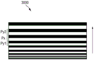
fig. 13 schematically and exemplarily shows a second embodiment of a grating element of an X-ray detection system.
Detailed Description
Fig. 1 shows schematically and exemplarily an embodiment of an X-ray device 10 for grating-type phase contrast computed tomography. The X-ray device 10 comprises a source-detector arrangement 11 with an X-ray source 12 for emitting an X-ray beam of coherent or quasi-coherent radiation in a line pattern and further adapted for rotational movement about an axis of rotation relative to an object placed on a table 14. Furthermore, an X-ray detection system 16 is provided opposite the X-ray source 12, wherein during a radiation operation an object arranged on the table 14 is movable in a direction z parallel to the axis of rotation to position the object within a space 17 between the X-ray source 12 and the X-ray detection system 16. Generally, axial acquisition (without patient movement) as well as helical acquisition, i.e. acquisition when the patient is moved in direction z while the source-detector arrangement 11 is rotated, may be used. The X-ray detection system 16 is adapted to send data to a data processing unit or computing system 18, which is preferably connected to both the X-ray detection system 16 and the X-ray source 12. The computing system 18 may be disposed proximate to the X-ray device 10. Of course, the computing system may be located in different locations, such as different laboratories. An X-ray source 12 and an X-ray detection system 16 are arranged on the gantry 13. The gantry 13 is adapted for rotational movement about an axis of rotation relative to an object placed in the space 17.
Furthermore, a display device or console 20 is arranged near the console 14 to display information to a person operating the X-ray apparatus 10. Preferably, the display device 20 is movably mounted to allow individual adjustment according to the examination situation. The display device 20 may also include an interface unit to input information by a user. The display device 20 is coupled to the computing system 18, which includes a reconstruction processor 18 a. The computing system 18 is coupled to a data repository 19, and both the computing system 18 and the data repository 19 are coupled to the X-ray device 10.
Basically, the X-ray detection system 16 generates image data by exposing an object placed on the table 14 to X-ray beams emitted by the X-ray source 12, wherein the image data is further processed in the X-ray device 10 and the reconstruction processor 18 a.
Fig. 2 schematically and exemplarily shows an embodiment of an X-ray detection system 16 of the source-detector arrangement 11. In this arrangement, the X-ray source 15 comprises an anode 12 and a source grating element 22 (also referred to as G0) to emit an X-ray beam 20 of coherent or quasi-coherent radiation. The object 140 is arranged in the path of the X-ray beam 20 between the X-ray source 12 and the X-ray detection system 16. The X-ray detection system 16 comprises a first grating element or phase grating element 24 and a second grating element or analyzer grating element 26. The first grating element 24 may also be referred to as G1 and the second grating element 26 may also be referred to as G2. The first grating element 24 is arranged at a distance i from the X-ray source 12 with the source grating element 22 and the second grating element 26 is arranged at a distance d from the first grating element. A wavefront (wave front)28a is depicted having a uniform phase upon reaching the object 140, while a more distant phase front (phase front)28b is depicted having a phase relationship change within the wavefront relative to the phase shift imposed on the wavefront upon penetration of the object 140.
The wavefront then reaches the first grating element 24. The second grating element 26 is movable relative to the first grating element 24 for phase contrast image acquisition. However, it is also contemplated to move the first grating element 24 instead of the analyzer grating element 26 or G0.
The X-ray beam 20 passes through the first grating element 24, thereby generating an interference pattern which is analyzed by the second grating element 26 in combination with the detector pixel elements 8.
For clarity in fig. 2, the first grating elements 24 are depicted with a uniform pitch p and the second grating elements 26 are depicted with a uniform pitch q. However, a detailed illustration of an exemplary embodiment with respect to the pitch arrangement of both the first and second grating elements can be taken from fig. 12 or 13.
Fig. 3 schematically and exemplarily shows a conventional setup for a grating-type differential phase contrast CT with an X-ray source 12 'and a detection system 16'. The first and second grating elements (only one grating G 'is shown in fig. 3 for simplicity) are aligned with the rotation axis R and the phase stepping direction S' is in the rotation plane.
Such a conventional arrangement as shown in fig. 3, wherein the anode 120' of the X-ray source has a line pattern 121' for emitting radiation in a line pattern 21', may be used conventionally, as shown in fig. 4. The line pattern 121 'of the anode 120' looks like a vertical grating when viewed along the optical axis of the arrangement (middle pattern on the right in fig. 4). However, even for a rather small fan angle α ' (15 ° in the illustration of fig. 4), the projection of the line pattern 121' on the detection system leads to a deflection of the pattern 21', which deflection requires a uniform tilting of the first and second grating elements of the detection system. Assume that the anode 120' shown in fig. 4 has an anode angle of 8 °. Fig. 5 shows schematically and exemplarily an embodiment of an arrangement for a grating-type differential phase contrast CT with an X-ray source 12 and a detection system 16, wherein a first grating element and a second grating element (for simplicity, only one grating G is shown in fig. 5) are arranged in an orientation orthogonal to the rotation axis R. The phase stepping is performed in a phase stepping direction S parallel to the rotation axis R.
Existing filtered back-projection algorithms can be used by the detection system to reconstruct a gradient projection of the real part of the object of the refractive index in the direction of the axis of rotation from the measured values of the phase-front gradient in the direction of the axis of rotation. Especially when the use of a filtered back-projection algorithm is sufficient to reconstruct the first derivative of the electron density in the direction of the axis of rotation, it is indicated to use a filtered back-projection algorithm. Alternatively or additionally, an iterative reconstruction algorithm may be used.
Fig. 6 and 7 show schematically and exemplarily an embodiment of an anode 120 for use in the X-ray source 12 according to fig. 5 in a top view (fig. 6) and a side view (fig. 7). The anode 120 is of a rotary type and is arranged on a rotary shaft 122. The anode angle γ is again assumed to be 8 °, however, this anode angle is shown greatly exaggerated in fig. 7 for clarity. The rotating anode 120 is a structured anode adapted to emit an X-ray beam 20 of coherent or quasi-coherent radiation in a line pattern 21. The structured rotary anode 120 comprises strips 121 of different radiation emission, which are arranged parallel to the grating lines of the first grating and/or the grating lines of the second grating, which are denoted G in fig. 5. To compensate for mechanical tolerances and inaccuracies during the production process of mounting the anode on the anode shaft 122, the X-ray source 12 is preferably provided with a position sensor and a beam deflection unit with an integrated controller, as described further below with respect to fig. 8.
The rotating anode 120 may also be unstructured and the line pattern is generated by directly electromagnetically forming an electron beam in a line pattern that impinges on the anode.
As can be seen from fig. 6, by rotating the line pattern 121 of the anode 120 by 90 ° compared to the conventional orientation shown in fig. 4, the orientation of the projected line pattern 21 no longer changes with the fan angle α. However, in this arrangement, the effective pitch of the projected line pattern 21 varies with the cone angle β, as can be seen from fig. 7. This is compensated in the detection system by a corresponding variation of the pitch of the first and second grating elements, as schematically and exemplarily shown in fig. 12 and 13.
Fig. 8 shows schematically and exemplarily an embodiment of elements of an X-ray source comprising a system for measuring and compensating a periodic oscillation of an anode tilt angle for use with, for example, the anode 120 of fig. 6 and 7. In fig. 8, a schematic cross-sectional view of a rotary anode 120 is shown with a rotary anode shaft 122 mounted obliquely. This typically results in a periodic change of the position of the focal spot 123 on the target surface of the anode 120, such that the focal spot may be blurred. In fig. 8, two different rotation phases of the rotary anode 120, which is mounted obliquely on its rotary anode shaft 122, are shown by way of example in a schematic cross-sectional view. These rotation phases of the rotation angle shifted by 180 ° with respect to each other show different inclination angles of the rotating anode 120 with respect to the rotation plane of the rotating anode. The plane of rotation is oriented perpendicular to the axis of rotation of the rotating shaft 122. The position sensor 40 is arranged to measure the phase-resolved focal spot position of the anode for various conditions that may have an effect on distortion wobble effects, e.g. by bending of the anode disc due to thermal conditions. Based on this measurement, control data obtained from the measurement results of the position sensor 40 may be supplied to an integrated beam deflection unit 51 for steering the electron beam 50 emitted by the cathode of the X-ray source accordingly. If the anode 120 is rotated in Or
Or Rotated 180 deg. in direction, the position of the
 focal spot 123 deviates by a deviation amplitude az in the direction of the axis of rotation of the anode shaft. Via the beam deflection unit 51, the electron beam 50 is steered such that the position of the focal spot 123 remains in the plane P of the central radiation fan beam. Without such a correction of the direction of the electron beam 50, the X-ray image may be blurred if az reaches a significant fraction of the projected focal spot diameter al and if the X-ray pulse length is about half the anode rotation period or longer.
Fig. 9 shows schematically and exemplarily an embodiment of a liquid metal jet arrangement for use in an X-ray source as used in the arrangement of fig. 5, for example. The electron beam structure 52 comprises a plurality 53 of individual electron beams 54 supplied as sub-electron beams. The pattern 46 is indicative of the generated radiation. A single electron beam 54 is supplied to a plurality of liquid metal jets 124. These liquid metal jets 124 provide a plurality of focal lines 125 and form an anode structure that results in the generation of a plurality of X-ray beams 46 to be used as an X-ray source.
Fig. 10 shows schematically and exemplarily the energy dependence on the cone angle in keV on the vertical axis, which is converted into a dependence on the distance from the central plane in mm on the horizontal axis, i.e. a dependence on the system coverage. For the example shown in fig. 10, the geometry of the example system with an anode angle of 8 ° (left) or 12 ° (right), a distance between the X-ray source and the rotation axis of 570mm and a design energy at a cone angle of 0 ° of 70keV have been assumed. As can be seen in fig. 10, for a system with 20mm coverage and an anode angle of 8 °, the variation in grating pitch causes the design energy to vary from approximately 55keV to 91 keV. Furthermore, this variation strongly depends on the anode angle, as can be seen from a comparison of the right and left part of fig. 10, wherein the variation is reduced to the range of 60keV to 83keV by increasing the anode angle to 12 °.
Fig. 11 shows schematically and exemplarily an embodiment of a method of generating and detecting an X-ray beam using a source-detector arrangement of an X-ray device for grating-type phase contrast computed tomography having a step 1001 of rotating an X-ray source emitting an X-ray beam of coherent or quasi-coherent radiation relative to an object around an axis of rotation and a step 1002 of detecting the radiation by an X-ray detection system comprising first and second grating elements and detector elements, wherein said line pattern of said radiation and a grating direction of said grating elements are arranged orthogonal to said axis of rotation; and the first grating element has a first grating pitch that varies in dependence on a cone angle of the X-ray beam and the second grating element has a second grating pitch that varies in dependence on the cone angle of the X-ray beam.
Fig. 12 schematically and exemplarily shows a first embodiment of a grating element 2000 of an X-ray detection system, which may be used as a first grating element and/or a second grating element, which grating element has a gradually or stepwise varying grating pitch along a cone angle of an X-ray beam. The grating element 2000 shown in fig. 12 has three different grating pitch sections 2100, 2200, 2300, with the same grating pitch within each of the sections, but with different grating pitches within different grating pitch sections. In other words, the grating pitch p of the grating pitch section 21001aIdentical within grating pitch section 2100, grating pitch p of grating pitch section 22001bAre the same within the grating pitch section 2200, and the grating pitch p of the grating pitch section 23001cAre identical within grating pitch zone 230. However, the grating pitch p of the three grating pitch sections 2100, 2200, 23001a、p1b、p1cDifferent from each other, in particular, the grating pitch p of the grating pitch section 23001cGrating pitch p greater than grating pitch section 22001bThe grating pitch p1bAnd greater than the grating pitch p of the grating pitch section 21001a。
Fig. 13 schematically and exemplarily shows a second embodiment of a grating element 3000 of an X-ray detection system, which grating element can be used as a first grating element and/or a second grating element, which grating element has a grating pitch that varies uniformly or monotonically along the cone angle of the X-ray beam. Each grating line and adjacent grating line p of grating element 3000 shown in fig. 13y1、py2Compared with having a different grating pitch px. In the embodiment shown in FIG. 13, the grating pitch pxIncreasing with each grating line in the direction indicated by the arrow shown in fig. 13.
Furthermore, it should be noted that the medical computed tomography system given in this description is intended only as an exemplary representation of an alternative application of the invention. At least one embodiment of the present invention may be used in conjunction with additional systems for examining biological or inorganic samples as well, without departing from the scope of the present application. In particular, at least one embodiment of the invention is also applicable to a system for substance analysis.
Other variations to the disclosed embodiments can be understood and effected by those skilled in the art in practicing the claimed invention, from a study of the drawings, the disclosure, and the appended claims.
In the claims, the word "comprising" does not exclude other elements or steps, and the indefinite article "a" or "an" does not exclude a plurality.
A single unit or device may fulfill the functions of several items recited in the claims. The mere fact that certain measures are recited in mutually different dependent claims does not indicate that a combination of these measures cannot be used to advantage.
The operations performed by one or several units or devices, such as the control of a source-detector arrangement or an X-ray device according to the method for generating and detecting an X-ray beam or for generating an image of an object, etc., may be performed by any other number of units or devices. The control of the source-detector arrangement or the X-ray device according to the method for generating and detecting an X-ray beam or for generating an image of an object may be implemented as program code means of a computer program and/or as dedicated hardware.
A computer program may be stored/distributed on a suitable medium, such as an optical storage medium or a solid-state medium supplied together with or as part of other hardware, and may also be distributed in other forms, such as via the internet or other wired or wireless telecommunication systems.
Any reference signs in the claims shall not be construed as limiting the scope.
The invention relates to a source-detector arrangement for an X-ray apparatus for grating-type phase contrast computed tomography. The source-detector arrangement comprises: an X-ray source adapted for rotational movement about an axis of rotation relative to an object and adapted to emit an X-ray beam of coherent or quasi-coherent radiation in a line pattern; and an X-ray detection system comprising first and second grating elements and a detector element; wherein the line pattern of the radiation and the grating direction of the grating elements are arranged orthogonal to the rotation axis; and the first grating element has a first grating pitch that varies in dependence on a cone angle of the X-ray beam and/or the second grating element has a second grating pitch that varies in dependence on the cone angle of the X-ray beam.
Claims (14)
1. Source-detector arrangement (11) for an X-ray device (10) for grating-type phase contrast computed tomography, the source-detector arrangement comprising:
an X-ray source (12) adapted for rotational movement about a rotational axis (R) relative to an object (140) and adapted to emit an X-ray beam of coherent or quasi-coherent radiation in a line pattern (21); and
an X-ray detection system (16) comprising first and second grating elements (24, 26) and a detector element (6); wherein the line pattern of the radiation and the grating direction of the grating elements are arranged orthogonal to the rotation axis; and the first grating element has a first grating pitch which varies in dependence on a cone angle (β) of the X-ray beam and/or the second grating element has a second grating pitch which varies in dependence on the cone angle of the X-ray beam.
2. The source-detector arrangement (11) according to claim 1, wherein the X-ray source comprises a source grating element (22) having a grating direction arranged orthogonal to the rotation axis.
3. Source-detector arrangement (11) according to claim 1, wherein the X-ray source (12) comprises an anode (120) for emitting the coherent or quasi-coherent radiation in a line pattern (21), the anode comprising strips (121) of different radiation emission, which strips are arranged parallel to the grating lines of the first grating element (24) and/or the grating lines of the second grating element (26).
4. The source-detector arrangement (11) according to claim 1, wherein the first grating pitch and/or the second grating pitch vary uniformly and/or gradually along the cone angle (β) of the X-ray beam.
5. The source-detector arrangement (11) according to claim 1, wherein the first grating pitch and/or the second grating pitch varies from a smaller grating pitch to a larger grating pitch along the cone angle (β) of the X-ray beam.
6. The source-detector arrangement (11) as claimed in claim 1, wherein the first grating element (24) and/or the second grating element (26) are adapted to be movable relative to each other to provide phase stepping.
7. Source-detector arrangement (11) according to claim 1, wherein the X-ray source (12) comprises a rotating anode (120) and a position sensor (40) for detecting recurring deviations of an actual position of a focal spot (123) of an electron beam (50) on a target region of the rotating anode relative to an expected position, and a beam deflection unit (51) with an integrated controller for deflecting the beam based on measurements obtained from the position sensor.
8. A source-detector arrangement (11) according to claim 1, wherein the X-ray source (12) comprises a structured electron beam (52) directed at an anode for emitting the coherent or quasi-coherent X-ray beam in a line pattern.
9. The source-detector arrangement (11) of claim 8, wherein the structured electron beam (52) is adapted to be electromagnetically movable to provide phase stepping.
10. The source-detector arrangement (11) of claim 1, wherein the X-ray source (12) comprises a plurality of liquid metal jets (124) providing a plurality of focal lines (125).
11. X-ray device (10) for grating-type phase contrast computed tomography, comprising a source-detector arrangement (11) according to claim 1.
12. Method for generating and detecting an X-ray beam using a source-detector arrangement (11) of an X-ray device (10) for grating-type phase contrast computed tomography, the method comprising:
rotating an X-ray source (12) emitting coherent or quasi-coherent radiation relative to an object (140) about an axis of rotation (R);
detecting the radiation by an X-ray detection system (16) comprising first and second grating elements and a detector element; wherein the line pattern of radiation and the grating direction of the grating elements are arranged orthogonal to the rotation axis; and the first grating element has a first grating pitch which varies in dependence on a cone angle (β) of the X-ray beam and/or the second grating element has a second grating pitch which varies in dependence on the cone angle of the X-ray beam.
13. Method for generating an image of an object using an X-ray device for grating-type phase contrast computed tomography, wherein the method for generating an image comprises the method for generating and detecting an X-ray beam according to claim 12, and the direction of the phase stepping is parallel to the axis of rotation.
14. Computer readable storage medium having stored a computer program for controlling an X-ray device for generating an image of an object, wherein the computer program comprises program code means for causing an X-ray device as defined in claim 11 to carry out the steps of the method for generating an image as defined in claim 13, when the computer program is run on a computer controlling the X-ray device.
Applications Claiming Priority (3)
| Application Number | Priority Date | Filing Date | Title |
|---|---|---|---|
| EP14192623.8 | 2014-11-11 | ||
| EP14192623 | 2014-11-11 | ||
| PCT/EP2015/076213 WO2016075140A1 (en) | 2014-11-11 | 2015-11-10 | Source-detector arrangement |
Publications (2)
| Publication Number | Publication Date |
|---|---|
| CN106999125A CN106999125A (en) | 2017-08-01 |
| CN106999125B true CN106999125B (en) | 2021-02-02 |
Family
ID=51945717
Family Applications (1)
| Application Number | Title | Priority Date | Filing Date |
|---|---|---|---|
| CN201580060997.2A Active CN106999125B (en) | 2014-11-11 | 2015-11-10 | Source-detector arrangement |
Country Status (5)
| Country | Link |
|---|---|
| US (1) | US10485492B2 (en) |
| EP (1) | EP3217879B1 (en) |
| JP (1) | JP7171190B2 (en) |
| CN (1) | CN106999125B (en) |
| WO (1) | WO2016075140A1 (en) |
Families Citing this family (25)
| Publication number | Priority date | Publication date | Assignee | Title |
|---|---|---|---|---|
| US10357222B2 (en) * | 2014-12-26 | 2019-07-23 | Hitachi, Ltd. | X-ray diagnostic imaging apparatus, monitoring server and anomaly detection method |
| US9561206B2 (en) * | 2015-01-07 | 2017-02-07 | The United States Of America, As Represented By The Secretary Of The Navy | Use of heptadecanoic acid (C17:0) to detect risk of and treat hyperferritinemia and metabolic syndrome |
| KR20180063164A (en) | 2015-09-28 | 2018-06-11 | 바라자 피티와이 엘티디 | Spatial profiling system and method |
| US10835193B2 (en) * | 2016-09-08 | 2020-11-17 | Koninklijke Philips N.V. | Source grating for X-ray imaging |
| DE102016217509A1 (en) * | 2016-09-14 | 2018-03-15 | Siemens Healthcare Gmbh | Method and X-ray device for generating a projective X-ray representation of an examination object |
| WO2018090085A1 (en) * | 2016-11-16 | 2018-05-24 | Baraja Pty Ltd | An optical beam director |
| EP3554369A1 (en) * | 2016-12-19 | 2019-10-23 | Koninklijke Philips N.V. | System and method for dark-field-imaging |
| US10872708B2 (en) * | 2017-07-24 | 2020-12-22 | Board Of Supervisors Of Louisiana State University And Agricultural And Mechanical College | Phase contrast X-ray interferometry |
| EP3446630A1 (en) | 2017-08-23 | 2019-02-27 | Koninklijke Philips N.V. | Device and method for phase stepping in phase contrast image acquisition |
| WO2019083816A1 (en) | 2017-10-23 | 2019-05-02 | Epitracker, Inc. | Fatty acid analogs and their use in the treatment of conditions related to metabolic syndrome |
| EP3502674A1 (en) * | 2017-12-19 | 2019-06-26 | Koninklijke Philips N.V. | Testing of curved x-ray gratings |
| WO2019130728A1 (en) * | 2017-12-25 | 2019-07-04 | 株式会社島津製作所 | Radiation phase contrast imaging device |
| US10845491B2 (en) | 2018-06-04 | 2020-11-24 | Sigray, Inc. | Energy-resolving x-ray detection system |
| GB2591630B (en) | 2018-07-26 | 2023-05-24 | Sigray Inc | High brightness x-ray reflection source |
| CN112823280A (en) | 2018-09-07 | 2021-05-18 | 斯格瑞公司 | System and method for depth-selectable X-ray analysis |
| TWI682160B (en) * | 2018-12-11 | 2020-01-11 | 國立交通大學 | Biological signal analysing device, biological sensing apparatus, sensing method and fabrication method of biological signal analysing device |
| WO2021046059A1 (en) | 2019-09-03 | 2021-03-11 | Sigray, Inc. | System and method for computed laminography x-ray fluorescence imaging |
| CN110664420B (en) * | 2019-10-11 | 2023-04-07 | 上海联影医疗科技股份有限公司 | Focus correction method, apparatus, computer device, and computer-readable storage medium |
| US20220390395A1 (en) * | 2019-11-01 | 2022-12-08 | Nova Measuring Instruments Inc. | Patterned x-ray emitting target |
| US11175243B1 (en) | 2020-02-06 | 2021-11-16 | Sigray, Inc. | X-ray dark-field in-line inspection for semiconductor samples |
| JP7395775B2 (en) | 2020-05-18 | 2023-12-11 | シグレイ、インコーポレイテッド | Systems and methods for X-ray absorption spectroscopy using a crystal analyzer and multiple detector elements |
| EP3925539A1 (en) | 2020-06-19 | 2021-12-22 | Koninklijke Philips N.V. | X-ray imaging system |
| JP2023542674A (en) | 2020-09-17 | 2023-10-11 | シグレイ、インコーポレイテッド | System and method for depth-resolved measurement and analysis using X-rays |
| WO2022126071A1 (en) | 2020-12-07 | 2022-06-16 | Sigray, Inc. | High throughput 3d x-ray imaging system using a transmission x-ray source |
| US11885755B2 (en) | 2022-05-02 | 2024-01-30 | Sigray, Inc. | X-ray sequential array wavelength dispersive spectrometer |
Citations (5)
| Publication number | Priority date | Publication date | Assignee | Title |
|---|---|---|---|---|
| CN101413905A (en) * | 2008-10-10 | 2009-04-22 | 深圳大学 | X ray differentiation interference phase contrast imaging system |
| CN101952900A (en) * | 2008-02-14 | 2011-01-19 | 皇家飞利浦电子股份有限公司 | The X-ray detector that is used for the phase correlation imaging |
| WO2011070519A1 (en) * | 2009-12-10 | 2011-06-16 | Koninklijke Philips Electronics N.V. | Scanning system for differential phase contrast imaging |
| CN102246256A (en) * | 2008-12-08 | 2011-11-16 | 皇家飞利浦电子股份有限公司 | Compensation of anode wobble for X-ray tubes of the rotary-anode type |
| CN102413767A (en) * | 2009-03-02 | 2012-04-11 | 罗切斯特大学 | Methods and apparatus for differential phase-contrast fan beam ct, cone-beam ct and hybrid cone-beam ct |
Family Cites Families (18)
| Publication number | Priority date | Publication date | Assignee | Title |
|---|---|---|---|---|
| DE10127269B4 (en) * | 2001-06-05 | 2015-09-24 | Siemens Aktiengesellschaft | Method for computed tomography and computed tomography (CT) device |
| WO2007074029A1 (en) | 2005-12-27 | 2007-07-05 | Siemens Aktiengesellschaft | Focus detector arrangement for generating phase-contrast x-ray images and method for this |
| DE102006037256B4 (en) | 2006-02-01 | 2017-03-30 | Paul Scherer Institut | Focus-detector arrangement of an X-ray apparatus for producing projective or tomographic phase contrast recordings and X-ray system, X-ray C-arm system and X-ray CT system |
| DE102006063048B3 (en) | 2006-02-01 | 2018-03-29 | Siemens Healthcare Gmbh | Focus / detector system of an X-ray apparatus for producing phase-contrast images |
| DE102006037254B4 (en) * | 2006-02-01 | 2017-08-03 | Paul Scherer Institut | Focus-detector arrangement for producing projective or tomographic phase-contrast images with X-ray optical grids, as well as X-ray system, X-ray C-arm system and X-ray computer tomography system |
| EP2073040A2 (en) * | 2007-10-31 | 2009-06-24 | FUJIFILM Corporation | Radiation image detector and phase contrast radiation imaging apparatus |
| JP2009133823A (en) | 2007-10-31 | 2009-06-18 | Fujifilm Corp | Radiation image detector and phase contrast radiation imaging apparatus |
| US8401144B2 (en) * | 2008-08-07 | 2013-03-19 | Koninklijke Philips Electronics N.V. | Method and apparatus for correcting artifacts in circular CT scans |
| DE102008048688B4 (en) * | 2008-09-24 | 2011-08-25 | Paul Scherrer Institut | X-ray CT system for generating tomographic phase-contrast or dark-field images |
| DE102009004702B4 (en) * | 2009-01-15 | 2019-01-31 | Paul Scherer Institut | Arrangement and method for projective and / or tomographic phase-contrast imaging with X-radiation |
| WO2010150136A1 (en) | 2009-06-22 | 2010-12-29 | Koninklijke Philips Electronics N. V. | Grating-based phase contrast x-ray imaging apparatus and methods |
| WO2012005128A1 (en) | 2010-07-05 | 2012-01-12 | Canon Kabushiki Kaisha | X-ray source, x-ray imaging apparatus, and x-ray computed tomography imaging system |
| JP2012143553A (en) | 2010-12-24 | 2012-08-02 | Fujifilm Corp | Radiographic apparatus and radiation image detector |
| JP5804843B2 (en) * | 2011-08-22 | 2015-11-04 | キヤノン株式会社 | X-ray imaging device |
| US9001967B2 (en) | 2012-12-28 | 2015-04-07 | Carestream Health, Inc. | Spectral grating-based differential phase contrast system for medical radiographic imaging |
| CN105190823B (en) | 2013-02-13 | 2017-11-17 | 皇家飞利浦有限公司 | multi X-ray beam tube |
| WO2014154188A1 (en) | 2013-03-26 | 2014-10-02 | Institute Of Experimental And Applied Physics | Method of phase gradient radiography and arrangement of an imaging system for application of the method |
| DE102013214393A1 (en) * | 2013-07-23 | 2014-11-20 | Siemens Aktiengesellschaft | X-ray system for differential phase-contrast imaging of an examination object with phase-stepping |
-
2015
- 2015-11-10 JP JP2017523461A patent/JP7171190B2/en active Active
- 2015-11-10 CN CN201580060997.2A patent/CN106999125B/en active Active
- 2015-11-10 WO PCT/EP2015/076213 patent/WO2016075140A1/en active Application Filing
- 2015-11-10 US US15/524,112 patent/US10485492B2/en active Active
- 2015-11-10 EP EP15791642.0A patent/EP3217879B1/en active Active
Patent Citations (5)
| Publication number | Priority date | Publication date | Assignee | Title |
|---|---|---|---|---|
| CN101952900A (en) * | 2008-02-14 | 2011-01-19 | 皇家飞利浦电子股份有限公司 | The X-ray detector that is used for the phase correlation imaging |
| CN101413905A (en) * | 2008-10-10 | 2009-04-22 | 深圳大学 | X ray differentiation interference phase contrast imaging system |
| CN102246256A (en) * | 2008-12-08 | 2011-11-16 | 皇家飞利浦电子股份有限公司 | Compensation of anode wobble for X-ray tubes of the rotary-anode type |
| CN102413767A (en) * | 2009-03-02 | 2012-04-11 | 罗切斯特大学 | Methods and apparatus for differential phase-contrast fan beam ct, cone-beam ct and hybrid cone-beam ct |
| WO2011070519A1 (en) * | 2009-12-10 | 2011-06-16 | Koninklijke Philips Electronics N.V. | Scanning system for differential phase contrast imaging |
Also Published As
| Publication number | Publication date |
|---|---|
| JP7171190B2 (en) | 2022-11-15 |
| EP3217879B1 (en) | 2020-01-08 |
| US10485492B2 (en) | 2019-11-26 |
| EP3217879A1 (en) | 2017-09-20 |
| CN106999125A (en) | 2017-08-01 |
| US20170319149A1 (en) | 2017-11-09 |
| JP2017536879A (en) | 2017-12-14 |
| WO2016075140A1 (en) | 2016-05-19 |
Similar Documents
| Publication | Publication Date | Title |
|---|---|---|
| CN106999125B (en) | Source-detector arrangement | |
| JP6422123B2 (en) | Radiation image generator | |
| EP2509501B1 (en) | Phase contrast imaging | |
| JP5188721B2 (en) | Method of creating image by projection or tomography, X-ray computed tomography system, focus-detector system of X-ray apparatus, and X-ray system | |
| JP5056842B2 (en) | Radiation image capturing apparatus and radiation image capturing system | |
| KR101318221B1 (en) | X-ray imaging apparatus and x-ray imaging method | |
| EP3687403B1 (en) | X-ray imaging reference scan | |
| EP3307167B1 (en) | Tiled detector arrangement for differential phase contrast ct | |
| JP6187298B2 (en) | X-ray imaging system and image processing method | |
| JP5601909B2 (en) | X-ray imaging apparatus and X-ray imaging method using the same | |
| JP4959223B2 (en) | Tomography equipment | |
| JP2012090945A (en) | Radiation detection device, radiographic apparatus, and radiographic system | |
| JP6475315B2 (en) | X-ray imaging equipment | |
| KR102426991B1 (en) | radiographic imaging device | |
| Fu et al. | Analysis and correction of dynamic geometric misalignment for nano-scale computed tomography at BSRF | |
| Cai et al. | Dose efficiency consideration for volume-of-interest breast imaging using x-ray differential phase-contrast CT | |
| JPWO2018168621A1 (en) | Radiation image generator | |
| JP2006071472A (en) | Ct method and ct apparatus | |
| WO2019171920A1 (en) | Radiation phase imaging device | |
| Safca et al. | PERSPECTIVE ON USING TALBOT-LAU X-RAY PHASE CONTRAST IMAGING FOR ATHEROSCLEROSIS DIAGNOSIS | |
| JP2020038153A (en) | Radiation image generating device | |
| Miaoa et al. | Classification: Physical Sciences, Applied Physical Sciences | |
| Viermetz et al. | Dark-Field for Human CT–Realization of a Talbot-Lau Interferometer in a Clinical CT Gantry |
Legal Events
| Date | Code | Title | Description |
|---|---|---|---|
| PB01 | Publication | ||
| PB01 | Publication | ||
| SE01 | Entry into force of request for substantive examination | ||
| SE01 | Entry into force of request for substantive examination | ||
| GR01 | Patent grant | ||
| GR01 | Patent grant |