Detailed Description
The technical solution in the embodiments of the present invention will be clearly and completely described below with reference to the accompanying drawings in the embodiments of the present invention. It is to be understood that the described embodiments are merely exemplary of the invention, and not restrictive of the full scope of the invention. All other embodiments, which can be derived by a person skilled in the art from the embodiments given herein without making any creative effort, shall fall within the protection scope of the present invention.
In the description of the present invention, it is to be understood that the terms "center", "longitudinal", "lateral", "length", "width", "thickness", "upper", "lower", "front", "rear", "left", "right", "vertical", "horizontal", "top", "bottom", "inner", "outer", "clockwise", "counterclockwise", and the like, indicate orientations and positional relationships based on those shown in the drawings, and are used only for convenience of description and simplicity of description, and do not indicate or imply that the device or element being referred to must have a particular orientation, be constructed and operated in a particular orientation, and thus, should not be considered as limiting the present invention. Furthermore, the terms "first", "second" and "first" are used for descriptive purposes only and are not to be construed as indicating or implying relative importance or implicitly indicating the number of technical features indicated. Thus, features defined as "first", "second", may explicitly or implicitly include one or more of the described features. In the description of the present invention, "a plurality" means two or more unless specifically defined otherwise.
In the description of the present invention, it should be noted that, unless otherwise explicitly specified or limited, the terms "mounted," "connected," and "connected" are to be construed broadly, e.g., as meaning either a fixed connection, a removable connection, or an integral connection; may be mechanically connected, may be electrically connected or may be in communication with each other; either directly or indirectly through intervening media, either internally or in any other relationship. The specific meanings of the above terms in the present invention can be understood by those skilled in the art according to specific situations.
In the present invention, unless otherwise expressly stated or limited, "above" or "below" a first feature means that the first and second features are in direct contact, or that the first and second features are not in direct contact but are in contact with each other via another feature therebetween. Also, the first feature being "on," "above" and "over" the second feature includes the first feature being directly on and obliquely above the second feature, or merely indicating that the first feature is at a higher level than the second feature. A first feature being "under," "below," and "beneath" a second feature includes the first feature being directly under and obliquely below the second feature, or simply meaning that the first feature is at a lesser elevation than the second feature.
The following disclosure provides many different embodiments or examples for implementing different features of the invention. To simplify the disclosure of the present invention, the components and arrangements of specific examples are described below. Of course, they are merely examples and are not intended to limit the present invention. Furthermore, the present invention may repeat reference numerals and/or letters in the various examples, such repetition is for the purpose of simplicity and clarity and does not in itself dictate a relationship between the various embodiments and/or configurations discussed. In addition, the present invention provides examples of various specific processes and materials, but one of ordinary skill in the art may recognize applications of other processes and/or uses of other materials.
Referring to fig. 1 and 2, the mobile terminal 100 includes a cover plate 10, a display 20, a circuit board 30, a battery 40, and a case 50.
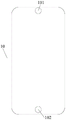
Wherein the cover plate 10 is mounted to the display screen 20 to cover the display screen 20. Referring to fig. 3, the cover plate 10 is formed with a through hole 101 and a through hole 102. Through holes 101 and 102 are provided at both ends of the cap plate 10, respectively. The through hole 101 may be used to allow a receiver in the mobile terminal 100 to transmit a sound signal to the outside through the through hole. The through hole 102 may be used to enable a fingerprint module in the mobile terminal 100 to collect user fingerprint information through the through hole.
In some embodiments, the through-hole 101 may be provided in the middle of the top end of the cap plate 10. The through-hole 102 may be provided at the middle of the bottom end of the cap plate 10.
The cover plate 10 may be a transparent glass cover plate. In some embodiments, the cover plate 10 may be a glass cover plate made of a material such as sapphire.
The display screen 20 is mounted on the housing 50 to form a display surface of the mobile terminal 100. Referring to fig. 4, the display screen 20 includes a display area 201 and a non-display area 202. The display area 201 is used to display information such as images and texts. The non-display area 202 does not display information. The bottom of the non-display area 202 may be provided with functional elements such as a fingerprint module and a touch circuit.
The display area 201 has a through hole 203. The through-hole 203 is located opposite to the through-hole 101 in the cover plate 10. The through hole 203 may be used to enable a camera in the mobile terminal 100 to capture an external image signal through the through hole, to enable a proximity sensor in the mobile terminal 100 to transmit and receive a signal through the through hole, and to enable a receiver in the mobile terminal 100 to transmit a sound signal to the outside through the through hole.
The non-display area 202 has a through hole 204. The through-hole 204 is located opposite to the through-hole 102 in the cover plate 10. The through hole 204 may be used to enable the fingerprint module in the mobile terminal 100 to collect the user fingerprint information through the through hole.
In some embodiments, the through hole 203 may be disposed in the middle of the top end of the display area 201. The through-hole 204 may be disposed at the bottom center of the non-display area 202.
The circuit board 30 is mounted inside the housing 50. The circuit board 30 may be a main board of the mobile terminal 100. Functional components such as a camera, a proximity sensor, and a receiver may be integrated on the circuit board 30. Meanwhile, the display screen 20 may be electrically connected to the circuit board 30.
Referring to fig. 5, the camera 31 may be integrated on the circuit board 30. The camera 31 may include a base 311 and a lens 312. The lens 312 is mounted on the base 311. The outline of the base 311 may be rectangular or circular. The outline size of the base 311 is larger than that of the lens 312 so that a step 310 is formed at the mounting surface of the lens 312 and the base 311. The step surface of the step 310 faces the display screen 20 in the mobile terminal 100.
The step 310 has the sensor assembly 32 mounted thereon. The sensor assembly 32 includes a signal transmitter 321 and a signal receiver 322. The signal transmitter 321 and the signal receiver 322 may constitute a proximity sensor. The signal transmitter 321 and the signal receiver 322 are electrically connected to the circuit board 30.
The signal transmitter 321 is used for transmitting a signal, and the signal receiver 322 is used for receiving a reflected signal formed by the signal reflected by an external object. The mobile terminal 100 may determine a distance state between the mobile terminal 100 and an external object according to the intensity of the reflected signal, thereby controlling the display state of the display screen 20.
The signal may be an optical signal such as infrared ray or laser, or may be another type of signal.
Among them, the signal transmitter 321 and the signal receiver 322 may be disposed at opposite sides of the lens 312 in a width direction of the mobile terminal 100. The signal transmitter 321 and the signal receiver 322 may also be disposed at opposite sides of the lens 312 in a length direction of the mobile terminal 100.
Since the step 310 is formed on the camera head 31, the sensor assembly 32 can be mounted on the step 310, so that a separate opening for the sensor assembly 32 is not required on the mobile terminal 100. Therefore, the occupation of the display area on the screen of the mobile terminal 100 by the sensor assembly 32 can be reduced, that is, the screen occupation ratio of the display area of the screen can be increased.
Referring to fig. 6, the sensor assembly 32 may also include an ambient light sensor 323. An ambient light sensor 323 is disposed around the lens 312 and mounted to the step 310. The ambient light sensor 323 is also electrically connected to the circuit board 30. The ambient light sensor 323 is for receiving an ambient light signal. The mobile terminal 100 may adjust the brightness of the display screen 20 according to the intensity of the ambient light signal.
Referring to fig. 7, the receiver 33 may be integrated on the circuit board 30. The receiver 33 may be composed of a vibration part 33-1, a magnetic circuit part 33-2, and a support part 33-3. The support portion 33-3 forms a housing of the receiver 33. The magnetic circuit portion 33-2 is mounted inside the case to form a magnetic circuit. The vibration part 33-1 is installed above the magnetic circuit part 33-2, and the vibration part 33-1 generates sound by vibration.
Wherein the vibration portion 33-1 includes a diaphragm 331 and a voice coil 332. The voice coil 332 is disposed at one side of the diaphragm 331 and connected to the diaphragm 331. There are various ways to connect the voice coil 332 and the diaphragm 331. For example, the voice coil 332 may be connected to the diaphragm 331 by bonding.
The diaphragm 331 may be a transparent film to allow an optical signal to pass through. The shape of the diaphragm 331 is adapted to the shape of the receiver 33. The diaphragm 331 may be circular in shape.
The diaphragm 331 is a thin film having high elasticity and can vibrate up and down in the thickness direction of the diaphragm. When the diaphragm 331 vibrates, the air on both sides of the diaphragm is driven to vibrate, so as to generate sound.
The voice coil 332 is formed by winding a wire having an insulating outer layer around an insulating bobbin. The leads on the voice coil 332 are used to connect audio circuitry inside the mobile terminal 100.
The magnetic circuit portion 33-2 includes a permanent magnet 333, a magnetic conductive plate 334, and a magnetic conductive plate 335. Here, the magnetic conductive sheet 334 may be disposed on one side (N-pole side) of the permanent magnet 333, and the magnetic conductive plate 335 may be disposed on the other side (S-pole side) of the permanent magnet 333. The magnetic conductive sheets 334 and the magnetic conductive plates 335 are used to conduct magnetic induction lines emitted from the permanent magnets 333, thereby forming a closed magnetic circuit. The magnetic induction line emitted from the N pole of the permanent magnet 333 passes through the magnetic conductive sheet 334, then passes through the magnetic conductive plate 335, and finally enters the S pole of the permanent magnet 333 to form a closed loop. The magnetically permeable sheet 334 may be a ferrous sheet. The magnetically permeable plate 335 may be a thin plate of iron. The shape of the magnetic conductive sheet 334 and the magnetic conductive plate 335 can be square, rectangular or circular. The magnetic conductive sheet 334, the permanent magnet 333, and the magnetic conductive plate 335 may be fixed by adhesion.
The permanent magnet 333 is provided with an opening 330, the magnetic conductive sheet 334 is provided with an opening 340, and the magnetic conductive plate 335 is provided with an opening 350. Openings 340, 350 both correspond to the position of opening 330.
The transparent diaphragm 331, the opening 340, the opening 330, and the opening 350 together form an optical signal path to allow an optical signal to pass through.
In some embodiments, the permanent magnet 333 is a nano permanent magnet. Namely, a layer of soft magnetic material is uniformly coated on the particles of the permanent magnetic material by utilizing a nanotechnology, or the permanent magnetic material and the soft magnetic material are mutually compounded by a chemical method (for example, a replacement reaction), so that the permanent magnetic nanoparticles are obtained. Then, the nano permanent magnet is prepared by the technological modes of high-pressure forming, high-temperature sintering and the like. Compared with the common neodymium iron boron permanent magnet, the nano permanent magnet has higher internal magnetic induction intensity. Therefore, when the volume of the permanent magnet is the same, the receiver adopting the nanometer permanent magnet has higher sound pressure level.
In some embodiments, the magnetically permeable plate 335 is U-shaped. The permanent magnets 333 and the magnetic conductive plates 334 are arranged at the U-shaped bottom of the magnetic conductive plate 335. The extensions on both sides of the magnetic conductive plate 335 extend upward to both sides of the permanent magnet 333 and the magnetic conductive sheet 334. A gap is formed between the both-side extensions of the magnetic conductive plate 335, the permanent magnet 333, and both sides of the magnetic conductive plate 334, and the voice coil 332 is disposed in the gap.
The support portion 33-3 includes a bracket 336 and a protective cover 337. The support 336 is annular. The outer edge of one end of the bracket 336 is provided with an outer edge projection. The protective cover 337 has a ring shape. The middle of the protective cover 337 may be provided with an opening to allow sound generated from the diaphragm 331 to be transmitted to the outside. The section of the protective cover 337 is an inverted L-shape. An outer edge depression is provided at the outer edge of the protective cover 337. The protective cover 337 is mounted to the support 336 by mating the outer edge protrusions on the support 336 with the outer edge recesses on the protective cover 337. The diaphragm 331 is mounted to the support 336 by a mounting portion of the edge of the diaphragm. Wherein the mounting portion of the edge of the diaphragm 331 may be mounted to the bracket 336 by means of bonding.
In some embodiments, the material of the support 336 is a nano material. The material of the protective cover 337 may also be a nanomaterial. The support 336 and the protective cover 337 may be integrally formed by nano-material injection molding. The support 336 and the protective cover 337 made of nano materials have higher strength, which can improve the mechanical reliability of the receiver 33.
Referring to fig. 8, in the mobile terminal 100, both the camera 31 and the receiver 33 are mounted on the circuit board 30. The camera 31 is opposed to the optical signal path 34 in the receiver 33. The sensor assembly 32 may be mounted on a step of the camera head 31. Meanwhile, the sensor 32 is electrically connected to the circuit board 30. The sensor assembly 32 includes a signal transmitter 321 and a signal receiver 322. The signal transmitter 321 and the signal receiver 322 may be respectively disposed at both sides of the lens of the camera 31.
Continuing with reference to fig. 1 and 2.
Wherein the battery 40 is mounted inside the case 50. The battery 40 is used to supply power to the mobile terminal 100.
The case 50 serves to form an outer contour of the mobile terminal 100. The material of the housing 50 may be plastic or metal. The housing 50 may be integrally formed.
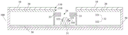
Referring to fig. 9, fig. 9 is a cross-sectional view of the mobile terminal shown in fig. 1 taken along a P-P direction. The cover plate 10 is mounted to the housing 50. The cover plate 10 is provided with an opening 110. The display screen 20 is also mounted to the housing 50. The display screen 20 is provided with an opening 210. Wherein the cover plate 10 covers the display screen 20. The position of the opening 210 is opposite to the position of the opening 110. The circuit board 30 is mounted inside the housing 50.
The camera 31 and the receiver 33 are mounted on the circuit board 30. The receiver 33 is disposed between the camera 31 and the display screen 20. The receiver 33 is opposite to the openings 210 and 110, so that the receiver 33 can transmit sound signals to the outside through the openings 210 and 110. The receiver 33 has an optical signal path 34 formed therein. The camera 31 is located opposite to the optical signal path 34, so that the camera 31 can collect an external optical signal through the optical signal path 34, the opening 210, and the opening 110.
Because the camera 31 is arranged below the receiver 33 along the thickness direction of the mobile terminal 100, independent holes do not need to be arranged on the display screen 20 for the camera 31 and the receiver 33 respectively, so that the occupation of the holes on the display screen 20 on a display area can be reduced, and the screen occupation ratio of the display area on the screen of the mobile terminal 100 can be improved.
In some embodiments, as shown in FIG. 10, the sensor assembly 32 may be mounted on the circuit board 30. The sensor assembly 32 is positioned opposite the optical signal path 34 on the receiver 33 such that the sensor assembly 32 can receive and/or transmit signals through the optical signal path 34, the opening 210, and the opening 110. The sensor assembly 32 includes a signal transmitter 321 and a signal receiver 322. The signal transmitter 321 and the signal receiver 322 may be disposed at both sides of the camera 31, respectively.
In some embodiments, the sensor assembly 32 may also include an ambient light sensor. An ambient light sensor may be disposed around camera head 31.
In some embodiments, as shown in FIG. 11, a step 310 is formed on the camera head 31. The step face of the step 310 faces the display screen 20. The sensor assembly 32 may be disposed on the step 310. The sensor assembly 32 includes a signal transmitter 321 and a signal receiver 322. The signal transmitter 321 and the signal receiver 322 may be respectively disposed at both sides of the lens of the camera 31.
In some embodiments, the sensor assembly 32 may also include an ambient light sensor. The ambient light sensor may be disposed on the step 310 and around the lens of the camera 31.
The mobile terminal provided by the embodiment of the present invention is described in detail above, and the principle and the implementation manner of the present invention are explained in this document by applying a specific example, and the description of the above embodiment is only used to help understanding the present invention. Meanwhile, for those skilled in the art, according to the idea of the present invention, there may be variations in the specific embodiments and the application scope, and in summary, the content of the present specification should not be construed as a limitation to the present invention.